JP2008166076A - Electronic device system and power supply control method - Google Patents
Electronic device system and power supply control methodDownload PDFInfo
- Publication number
- JP2008166076A JP2008166076AJP2006353371AJP2006353371AJP2008166076AJP 2008166076 AJP2008166076 AJP 2008166076AJP 2006353371 AJP2006353371 AJP 2006353371AJP 2006353371 AJP2006353371 AJP 2006353371AJP 2008166076 AJP2008166076 AJP 2008166076A
- Authority
- JP
- Japan
- Prior art keywords
- output
- converter circuit
- fuel cell
- current
- circuit
- Prior art date
- Legal status (The legal status is an assumption and is not a legal conclusion. Google has not performed a legal analysis and makes no representation as to the accuracy of the status listed.)
- Withdrawn
Links
Images


Classifications
- Y—GENERAL TAGGING OF NEW TECHNOLOGICAL DEVELOPMENTS; GENERAL TAGGING OF CROSS-SECTIONAL TECHNOLOGIES SPANNING OVER SEVERAL SECTIONS OF THE IPC; TECHNICAL SUBJECTS COVERED BY FORMER USPC CROSS-REFERENCE ART COLLECTIONS [XRACs] AND DIGESTS
- Y02—TECHNOLOGIES OR APPLICATIONS FOR MITIGATION OR ADAPTATION AGAINST CLIMATE CHANGE
- Y02E—REDUCTION OF GREENHOUSE GAS [GHG] EMISSIONS, RELATED TO ENERGY GENERATION, TRANSMISSION OR DISTRIBUTION
- Y02E60/00—Enabling technologies; Technologies with a potential or indirect contribution to GHG emissions mitigation
- Y02E60/30—Hydrogen technology
- Y02E60/50—Fuel cells
Landscapes
- Fuel Cell (AREA)
- Charge And Discharge Circuits For Batteries Or The Like (AREA)
Abstract
Translated fromJapaneseDescription
Translated fromJapanese本発明は、燃料電池とバッテリによって駆動する電子機器システム、および電源制御方法に関する。 The present invention relates to an electronic device system driven by a fuel cell and a battery, and a power supply control method.
モバイル機器の電源として燃料電池が注目されている。燃料電池から一定の電力を出力させると共に、不足分をバッテリから出力される電力で補うハイブリッド型で駆動させる技術が開示されている(特許文献1)。
ところで、前述した文献の技術は、負荷の消費電力が変化せず、燃料電池の出力が変動することを前提にした技術である。 By the way, the technique of the literature mentioned above is a technique on the assumption that the power consumption of the load does not change and the output of the fuel cell fluctuates.
ノートブック型パーソナルコンピュータのように、消費電力が変化する機器(負荷回路)の場合のことは考慮されていない。 The case of a device (load circuit) whose power consumption changes like a notebook personal computer is not considered.
本発明の目的は、燃料電池および二次電池から並列的に出力される電力を用いて消費電力が変化する負荷回路を駆動することを可能にする電子機器システムおよび電源制御方法を提供することにある。 An object of the present invention is to provide an electronic device system and a power supply control method that make it possible to drive a load circuit whose power consumption changes using power output in parallel from a fuel cell and a secondary battery. is there.
本発明の一例に係わる電子機器システムは、燃料電池スタックからの出力を昇圧すると共に、入力電流の電流値または前記燃料電池スタックの出力電流値を一定に制御する第1DC/DCコンバータ回路と、放電モードを有し、前記放電モード時に二次電池からの出力を昇圧すると共に、出力電流の電流値に応じて出力電圧の電圧値を制御する第2DC/DCコンバータ回路と、前記第1DC/DCコンバータ回路の出力と前記第2DC/DCコンバータ回路の出力とを結合するための結合回路とを具備することを特徴とする。 An electronic device system according to an example of the present invention includes a first DC / DC converter circuit that boosts an output from a fuel cell stack and controls a current value of an input current or an output current value of the fuel cell stack to be constant, and a discharge And a second DC / DC converter circuit for boosting the output from the secondary battery during the discharge mode and controlling the voltage value of the output voltage in accordance with the current value of the output current, and the first DC / DC converter A coupling circuit for coupling an output of the circuit and an output of the second DC / DC converter circuit is provided.
燃料電池および二次電池から並列的に出力される電力を用いて消費電力が変化する負荷回路を駆動することを可能になる。 It becomes possible to drive a load circuit whose power consumption changes using power output in parallel from the fuel cell and the secondary battery.
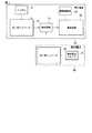
まず、図1を参照して、本発明の一実施形態に係る電子機器システムの構成を説明する。 First, the configuration of an electronic device system according to an embodiment of the present invention will be described with reference to FIG.
この電子機器10は、例えば、パーソナルコンピュータ、PDA、AVプレーヤ、のような携帯型機器であり、内蔵電池および外部電池によって駆動可能に構成されている。内蔵電池としては、二次電池から構成されるバッテリ11が用いられる。また、外部電池としては、燃料電池20が用いられる。 The
電子機器10の本体内には、バッテリ11に加え、DC/DCコンバータ回路12、結合回路、電源制御部14および負荷回路15が設けられている。DC/DCコンバータ回路12は、バッテリ11から負荷回路15に供給すべき電力を生成するスイッチング電源回路であり、例えば降圧型スイッチングレギュレータなどから構成されている。電子機器10の本体内には、DC/DCコンバータ回路12および燃料電池20の出力を結合して負荷回路15に供給する結合回路13が設けられている。 In the main body of the
DC/DCコンバータ回路12は、負荷回路15に電力を供給する放電モードと、燃料電池20の電力を用いてバッテリ11を充電する充電モードとを有する。放電モードにおいては、デューティ比が変化する固定周波数パルス幅変調信号(PWM信号)を用いてスイッチング素子がスイッチング制御される。 The DC /
負荷回路15は、例えば、CPU、またはI/Oデバイス等などであり、処理状況に応じて消費電力が変化する。 The
電源制御部14は、負荷回路15の動作状態を監視する。電源制御部14は、負荷回路15の消費電力が燃料電池20の出力電力以上の場合に、DC/DCコンバータ回路12に放電モードを設定する。また、電源制御部14は、負荷回路15の消費電力が燃料電池20の出力電力より低く電力が余る場合に、DC/DCコンバータ回路12に充電モードを設定する。 The power supply control unit 14 monitors the operating state of the
燃料電池20は、燃料電池スタック21およびDC/DCコンバータ回路22が設けられている。燃料電池20の本体内には、燃料電池スタック21から負荷回路15に供給すべき電力を生成するスイッチング電源回路である。DC/DCコンバータ回路22は、入力電流の電流値または燃料電池スタック22の出力電流値を一定に制御する。 The
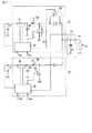
次に、図2を参照して、DC/DCコンバータ回路12,22、および結合回路13の具体的な構成例を説明する。 Next, a specific configuration example of the DC /
DC/DCコンバータ回路12は、電流検出抵抗31、第1スイッチング素子32、第2スイッチング素子33、インダクタ34、バッテリ制御部35、およびキャパシタ36等を有する。 The DC /
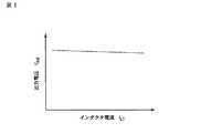
放電モード時、バッテリ制御部35は、電流検出抵抗31によってインダクタ34に流れる電流IL1を検出する。バッテリ制御部35は、図3に示すように、電流IL1に比例して出力電圧Voutを僅かに下げる制御を行う。In the discharge mode, the
充電モード時、バッテリ制御部35は、電流IL1を制御する。このとき電流IL1はバッテリ11への充電電流となり、バッテリ制御部35は、充電電流と電圧を所定の充電条件Iref1、Vref1を満足するようスイッチング素子32を制御する。In the charging mode, the
放電モード時には、スイッチング素子33がオンで且つスイッチング素子32がオフの状態で、バッテリ11の出力電圧によってインダクタ34にエネルギーが蓄えられる。その後、スイッチング素子33がオフに切り換えられると共にスイッチング素子32がオンに切り換えられると、インダクタ34に蓄えられたエネルギーが、スイッチング素子32MOSFETのソース−ドレイン間及び整流素子としてのダイオードを経て、結合回路13に供給される。この様に同期整流方式によって昇圧放電動作が実行される。 In the discharge mode, energy is stored in the
一方、充電モード時には、スイッチング素子32がオンで且つスイッチング素子33がオフ状態で、燃料電池スタック21から出力される電力がインダクタ34を経てバッテリ11に供給され、充電が行われる。その後、スイッチング素子32がオフに切り換えられると共にスイッチング素子33がオンに切り換えられると、並びにスイッチング素子33を構成するMOSFETのソース−ドレイン間及びダイオードに電流が流れて、インダクタ34に蓄えられたエネルギーがキャンセルされる。この様にして降圧充電動作が実行される。 On the other hand, in the charging mode, the
DC/DCコンバータ回路22は、電流検出抵抗41、第3スイッチング素子43、インダクタ44、FC制御部45、およびキャパシタ46等を有する。 The DC /
燃料電池ユニットに設けられたFC制御部45は、図4に示すように電源制御部14から供給される定電流指令値Iref2に従って定電流制御を行う。FC制御部45は、電流検出抵抗41によりインダクタ44に流れる電流IL2の平均値を検出する。FC制御部45は、電流IL2が定電流指令値Iref2に追随するように制御する。The
また、FC制御部45は、電源制御部14から供給される燃料電池スタックの下限電圧指令値Vref2より燃料電池スタック21の出力電圧が低下しないよう電流IL2を制御する制御を行う。なお、この下限電圧制御は定電流制御よりも優先される。Further, the
放電モード時では、2つのDC/DCコンバータ回路12,22の出力が平滑コンデンサ51に入力されることにより結合する。図5に示すように、その出力電圧Voutの制御は主としてバッテリ制御部35により為される。FC制御部45は燃料電池スタック21の出力電流IL2とその下限電圧を制御する。負荷回路15の消費電力と燃料電池スタック21の発電電力の差分の不足分はバッテリ11から電力供給可能される。In the discharge mode, the outputs of the two DC /
これにより、上記一組の昇圧型DC/DCコンバータによりスタックとL+バッテリーによるハイブリッド制御が可能となる。 Thereby, hybrid control by the stack and the L + battery can be performed by the set of step-up DC / DC converters.
軽負荷等で燃料電池スタック21の発電電力が余る場合はDC/DCコンバータ回路12内の電力の流れを反対方向とし、DC/DCコンバータ回路12をバッテリ11が負荷となる降圧型DC/DCコンバータとして動作させる。すなわちスイッチング素子33によるスイッチングを停止し、スイッチング素子32により電流IL1を制御する。このとき電流IL1はバッテリ11への充電電流となり、バッテリ制御部25は充電電流とバッテリ11の電圧を電源制御部14から供給される充電条件Iref1、Vref1を満足するようスイッチング素子32を制御する。When the generated power of the
これにより、上記一組の昇圧型DC/DCコンバータによりスタックとL+バッテリーによるハイブリッド制御が可能となる。 Thereby, hybrid control by the stack and the L + battery can be performed by the set of step-up DC / DC converters.
なお、本発明は、上記実施形態そのままに限定されるものではなく、実施段階ではその要旨を逸脱しない範囲で構成要素を変形して具体化できる。また、上記実施形態に開示されている複数の構成要素の適宜な組み合せにより種々の発明を形成できる。例えば、実施形態に示される全構成要素から幾つかの構成要素を削除してもよい。更に、異なる実施形態に亘る構成要素を適宜組み合せてもよい。 Note that the present invention is not limited to the above-described embodiment as it is, and can be embodied by modifying the constituent elements without departing from the scope of the invention in the implementation stage. Further, various inventions can be formed by appropriately combining a plurality of constituent elements disclosed in the embodiment. For example, some components may be deleted from all the components shown in the embodiment. Furthermore, you may combine suitably the component covering different embodiment.
10…電子機器,11…バッテリ,12…DC/DCコンバータ回路,13…結合回路,14…電源制御部,15…負荷回路,20…燃料電池,21…燃料電池スタック,22…DC/DCコンバータ回路,31…電流検出抵抗,32…スイッチング素子,33…スイッチング素子,34…インダクタ,35…バッテリ制御部,36…キャパシタ,43…スイッチング素子,44…インダクタ,45…FC制御部,46…キャパシタ,51…平滑コンデンサ。 DESCRIPTION OF
Claims (10)
Translated fromJapanese放電モードを有し、前記放電モード時に二次電池からの出力を昇圧すると共に、出力電流の電流値に応じて出力電圧の電圧値を制御する第2DC/DCコンバータ回路と、
前記第1DC/DCコンバータ回路の出力と前記第2DC/DCコンバータ回路の出力とを結合するための結合回路と
を具備することを特徴とする電子機器システム。A first DC / DC converter circuit for boosting the output from the fuel cell stack and controlling the current value of the input current or the output current value of the fuel cell stack to be constant;
A second DC / DC converter circuit having a discharge mode, boosting the output from the secondary battery during the discharge mode, and controlling the voltage value of the output voltage according to the current value of the output current;
An electronic device system comprising a coupling circuit for coupling the output of the first DC / DC converter circuit and the output of the second DC / DC converter circuit.
第2DC/DCコンバータ回路によって、放電モード時に二次電池からの出力電圧を昇圧すると共に、出力電流の電流値に応じて出力電圧の電圧値を制御し、
前記第1DC/DCコンバータ回路からの出力と前記第2DC/DCコンバータ回路の出力とを結合して負荷回路に出力する電源制御方法。The first DC / DC converter circuit boosts the output voltage from the fuel cell stack and controls the current value of the input current or the output current value of the fuel cell stack to be constant.
The second DC / DC converter circuit boosts the output voltage from the secondary battery in the discharge mode, and controls the voltage value of the output voltage according to the current value of the output current.
A power supply control method for combining an output from the first DC / DC converter circuit and an output of the second DC / DC converter circuit and outputting the combined output to a load circuit.
Priority Applications (1)
| Application Number | Priority Date | Filing Date | Title |
|---|---|---|---|
| JP2006353371AJP2008166076A (en) | 2006-12-27 | 2006-12-27 | Electronic device system and power supply control method |
Applications Claiming Priority (1)
| Application Number | Priority Date | Filing Date | Title |
|---|---|---|---|
| JP2006353371AJP2008166076A (en) | 2006-12-27 | 2006-12-27 | Electronic device system and power supply control method |
Publications (1)
| Publication Number | Publication Date |
|---|---|
| JP2008166076Atrue JP2008166076A (en) | 2008-07-17 |
Family
ID=39695271
Family Applications (1)
| Application Number | Title | Priority Date | Filing Date |
|---|---|---|---|
| JP2006353371AWithdrawnJP2008166076A (en) | 2006-12-27 | 2006-12-27 | Electronic device system and power supply control method |
Country Status (1)
| Country | Link |
|---|---|
| JP (1) | JP2008166076A (en) |
Cited By (3)
| Publication number | Priority date | Publication date | Assignee | Title |
|---|---|---|---|---|
| WO2010052822A1 (en)* | 2008-11-05 | 2010-05-14 | トヨタ自動車株式会社 | Fuel battery system |
| US8410749B2 (en) | 2009-11-30 | 2013-04-02 | Kabushiki Kaisha Toshiba | Device and method for controlling the charging and discharging of a battery for supplying power from the battery and a fuel cell |
| JP2016095901A (en)* | 2014-11-12 | 2016-05-26 | トヨタ自動車株式会社 | Fuel cell system and fuel cell control method |
- 2006
- 2006-12-27JPJP2006353371Apatent/JP2008166076A/ennot_activeWithdrawn
Cited By (7)
| Publication number | Priority date | Publication date | Assignee | Title |
|---|---|---|---|---|
| WO2010052822A1 (en)* | 2008-11-05 | 2010-05-14 | トヨタ自動車株式会社 | Fuel battery system |
| JP2010113896A (en)* | 2008-11-05 | 2010-05-20 | Toyota Motor Corp | Fuel cell system |
| CN102204001A (en)* | 2008-11-05 | 2011-09-28 | 丰田自动车株式会社 | Fuel battery system |
| CN102204001B (en)* | 2008-11-05 | 2013-12-04 | 丰田自动车株式会社 | fuel cell system |
| US8815460B2 (en) | 2008-11-05 | 2014-08-26 | Toyota Jidosha Kabushiki Kaisha | Fuel cell system |
| US8410749B2 (en) | 2009-11-30 | 2013-04-02 | Kabushiki Kaisha Toshiba | Device and method for controlling the charging and discharging of a battery for supplying power from the battery and a fuel cell |
| JP2016095901A (en)* | 2014-11-12 | 2016-05-26 | トヨタ自動車株式会社 | Fuel cell system and fuel cell control method |
Similar Documents
| Publication | Publication Date | Title |
|---|---|---|
| US7288854B2 (en) | Power linear and switching regulators commonly controlled for plural loads | |
| JP3747381B2 (en) | Power supply control circuit for electronic devices with built-in batteries | |
| US8243472B2 (en) | Power supply having a two-way DC to DC converter | |
| EP1905149B1 (en) | Dual-input dc-dc converter with integrated ideal diode function | |
| KR101340204B1 (en) | Dc/dc voltage converter including up inductive switching pre-regulator and capacitive switching post-converter | |
| CN202798467U (en) | DC/DC converter, power supply device applying DC/DC converter, and electronic device | |
| JP5082339B2 (en) | Power converter | |
| US7528589B2 (en) | Step-up DC/DC converter and electronic appliance therewith | |
| JP4976086B2 (en) | Buck-boost DC-DC converter | |
| JP2009232665A (en) | Power supply device and power supply control method | |
| JP2008199804A (en) | POWER SUPPLY CIRCUIT FOR POWER SUPPLYING CHARGE CONTROL CIRCUIT, CHARGING DEVICE HAVING THE POWER SOURCE CIRCUIT, AND METHOD FOR POWER SUPPLYING CHARGE CONTROL CIRCUIT | |
| JP2007185065A (en) | Power supply device and electronic apparatus equipped with the same | |
| WO2012001525A2 (en) | Intelligent gate drive | |
| JP2008079378A (en) | Electronics | |
| CN101257253A (en) | Step-up switching power supply device and electronic equipment equipped with the power supply device | |
| CN114499194A (en) | Power supply control device | |
| JP2013247745A (en) | Charge control circuit and charging circuit | |
| CN102882240A (en) | Power management circuit and method | |
| TWI505593B (en) | Configurable power supply system and method of configuring power supply | |
| JP3206556B2 (en) | Buck-boost chopper DC-DC converter circuit | |
| US20130162237A1 (en) | Energy-based Oriented Switching Mode Power Supply | |
| WO2002099947A1 (en) | Power unit and method for power supply of power unit | |
| JP2007189771A (en) | Power supply | |
| JP2008166076A (en) | Electronic device system and power supply control method | |
| JP4379396B2 (en) | Buck-boost chopper type DC-DC converter |
Legal Events
| Date | Code | Title | Description |
|---|---|---|---|
| A621 | Written request for application examination | Free format text:JAPANESE INTERMEDIATE CODE: A621 Effective date:20090331 | |
| A761 | Written withdrawal of application | Free format text:JAPANESE INTERMEDIATE CODE: A761 Effective date:20101004 |