JP2008164434A - Biological sample discrimination device - Google Patents
Biological sample discrimination deviceDownload PDFInfo
- Publication number
- JP2008164434A JP2008164434AJP2006354297AJP2006354297AJP2008164434AJP 2008164434 AJP2008164434 AJP 2008164434AJP 2006354297 AJP2006354297 AJP 2006354297AJP 2006354297 AJP2006354297 AJP 2006354297AJP 2008164434 AJP2008164434 AJP 2008164434A
- Authority
- JP
- Japan
- Prior art keywords
- biological sample
- unit
- flow path
- quantification
- buffer
- Prior art date
- Legal status (The legal status is an assumption and is not a legal conclusion. Google has not performed a legal analysis and makes no representation as to the accuracy of the status listed.)
- Pending
Links
Images


Landscapes
- Investigating, Analyzing Materials By Fluorescence Or Luminescence (AREA)
- Investigating Or Analysing Biological Materials (AREA)
- Automatic Analysis And Handling Materials Therefor (AREA)
- Investigating Or Analysing Materials By Optical Means (AREA)
Abstract
Description
Translated fromJapanese本発明は、DNAやタンパクなど、生体サンプルを緩衝剤中で移動させ、その輸送反応を検出して生体サンプルを判別する生体サンプル判別装置に関するものであり、特に生体サンプルがきちんと流路に満たされていることを確認するのに好適に利用できるものである。 The present invention relates to a biological sample discriminating apparatus for discriminating a biological sample by moving a biological sample such as DNA or protein in a buffer and detecting its transport reaction, and in particular, the biological sample is properly filled in a flow path. It can be suitably used to confirm that the
従来の生体サンプル判別技術としては、キャプラリーと呼ばれるガラス管に緩衝剤や生体サンプルを充填して行うものがある。これは吸引あるいは加圧ポンプを使用し、まず容器の中にある前記緩衝剤を前記キャピラリーの中に充填し、次に別の容器にある生体サンプルの一定量分を、ポンプで吸引あるいは加圧しキャピラリーの中に順次詰めていく。 As a conventional biological sample discrimination technique, there is one performed by filling a glass tube called a caprary with a buffer or a biological sample. This is done by using a suction or pressurization pump, first filling the buffer with the buffer in the container, and then sucking or pressurizing a certain amount of biological sample in another container with the pump. The capillaries are packed sequentially.
キャピラリーの中に充填を行った後、キャピラリーの両側を緩衝剤の容器に浸けてその容器には電圧が印加できるように電極がついており、電極に電圧を印加することで、キャピラリーの中に電圧が印加されて緩衝剤中を生体サンプルが移動する。キャピラリーの一部には光が照射してあり、キャピラリーを挟んで反対側には光量を検出している光検出器が取り付けてある。 After the capillary is filled, electrodes are attached so that both sides of the capillary are immersed in a buffer container and voltage can be applied to the container. Is applied to move the biological sample through the buffer. A part of the capillary is irradiated with light, and a photodetector for detecting the amount of light is attached to the opposite side of the capillary.
生体サンプルが緩衝剤の中を移動し、キャピラリーに光を照射している部分を通過するときに得られる光量の増減を検出して生体サンプルの輸送反応を判定している。(例えば、特許文献1参照。)
上記の技術は、吸引あるいは加圧ポンプや緩衝剤・生体サンプルを入れる容器等装置が大掛かりになり取り扱いも不便であるため、より操作の簡単な技術の開発が進められている。たとえば、キャピラリーのかわりにアクリルなどのプレートに微小な溝をつけ流路とし、プレートを回転させ遠心力を用いて前記流路の中に緩衝剤を充填し生体サンプルを定量化して、流路の両側に電極をあて電圧を印加することで、この中を生体サンプルが移動することで起こる輸送反応を光学検出器で検出して判別するものがある。(例えば特許文献2参照)。
Since the above-described technique requires a large apparatus such as a suction or pressure pump, a buffer or a biological sample container, and is inconvenient to handle, development of a technique that is simpler to operate is being promoted. For example, instead of a capillary, a plate made of acrylic or the like is provided with a minute groove as a flow path, and the biological sample is quantified by rotating the plate and filling the flow path with a buffer using centrifugal force. There is one in which an electrode is applied to both sides and a voltage is applied to detect a transport reaction caused by the movement of a biological sample through the optical detector with an optical detector. (For example, refer to Patent Document 2).
しかしながら、上記の緩衝剤が注入される第1の流路と、該第1の流路と一部を共通にして生体サンプルが注入される第2の流路とを有するプレートレートを用いた装置にあっては、緩衝剤を第1の流路に充填した後に、第2の流路に生体サンプルを充填して、電気泳動に必要な所定量の生体サンプルを定量するのであるが、必ずしもきちんと定量が行えないことがある。 However, an apparatus using a plate rate having a first channel into which the above-mentioned buffer is injected and a second channel into which a biological sample is injected in common with the first channel. In this case, after filling the first flow path with the buffering agent, the second flow path is filled with the biological sample, and a predetermined amount of the biological sample necessary for electrophoresis is quantified. Quantification may not be possible.
つまり定量部に生体サンプルを充填できず、定量部が空のままであったり、第1の流路に生体サンプルが次々と流れ込んで定量部に所定量の生体サンプルを保持できなかったりした場合には、生体サンプルをきちんと定量できないため、電気泳動を行うことすらできず、輸送反応を検出できないという問題がある。 In other words, when the quantification unit cannot be filled with the biological sample and the quantification unit remains empty, or when the biological sample flows into the first channel one after another and the quantification unit cannot hold the predetermined amount of biological sample. However, since a biological sample cannot be accurately quantified, there is a problem that even a electrophoresis cannot be performed and a transport reaction cannot be detected.
生体サンプルが第1の流路に流れ込むという問題は、緩衝剤が第1の流路にきちんと満たされていない場合に生じやすく、第2の流路から定量部を通して第1の流路へ生体サンプルが次々と流れ込んでしまうのである。 The problem that the biological sample flows into the first flow path is likely to occur when the buffer is not properly filled in the first flow path, and the biological sample is transferred from the second flow path to the first flow path through the quantitative unit. Will flow in one after another.
本発明は、上記課題を解決するものであり、正確な電気泳動ができるように、緩衝剤を第1の流路に満たしたのち、第2の流路に生体サンプルを導入した直後に、定量すべき部分に、一定量の生体サンプルが注入されたかどうか、光学的に検出するようにするものである。 The present invention solves the above-mentioned problem, and after the buffer is filled in the first channel so that accurate electrophoresis can be performed, the quantitative determination is performed immediately after the biological sample is introduced into the second channel. Whether or not a certain amount of biological sample has been injected into the portion to be optically detected.
上記課題を解決するために、本発明の生体サンプル判別装置は、緩衝剤が流入する第1の流路と、その流路の一部に、第1の流路とその一部を共通とし、一定量の生体サンプルを保持する定量部を含み、定量部を含む流路に前記生体サンプルが流入される第2の流路と、を有する流路のパターンが形成されたプレートを備えるとともに、このプレートの第1の流路に緩衝剤を充填させた後に、この定量部を含む第2の流路に生体サンプルを充填させる充填ユニットと、定量部に存在する生体サンプルを緩衝剤中で移動させ、この緩衝剤中を移動する生体サンプルを判別する判別ユニットとを備える生体サンプル判別装置において、さらに、定量部に対して光照射する発光部と、前記定量部からの光を受光する受光部とからなる光学ユニットを備え、第2の流路に生体サンプルを充填させて、生体サンプルの定量動作を行った後に、定量部に生体サンプルが存在するか否かを、光学ユニットで検出するようにしたことを特徴とするものである。 In order to solve the above problems, the biological sample discriminating apparatus of the present invention has the first flow channel into which the buffer agent flows, a part of the flow channel, the first flow channel and a part thereof in common, A plate having a flow path pattern formed thereon, the flow path including the quantitative portion, and a second flow path through which the biological sample flows into the flow path including the quantitative portion. After filling the first flow path of the plate with the buffer, the filling unit for filling the second flow path including the quantification section with the biological sample, and the biological sample existing in the quantification section is moved in the buffer. A biological sample discriminating apparatus comprising a discriminating unit for discriminating a biological sample moving in the buffer, and further, a light emitting unit for irradiating light to the quantitative unit, and a light receiving unit for receiving light from the quantitative unit An optical unit consisting of The second flow channel is filled with the biological sample, and after the biological sample is quantified, the optical unit detects whether or not the biological sample exists in the quantification unit. To do.
本発明の生体サンプル判別装置によれば、生体サンプルをきちんと定量できたかどうかを、電気泳動を行う前に判別することができる。このため生体サンプルをきちんと定量できていない場合には、以降の分析を中止するなどできるため判別の精度を高めることができる。 According to the biological sample discriminating apparatus of the present invention, it is possible to discriminate whether or not a biological sample has been properly quantified before performing electrophoresis. For this reason, when the biological sample cannot be quantified properly, the subsequent analysis can be stopped, and the accuracy of the determination can be increased.
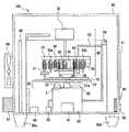
以下に、本発明の生体サンプル判別方法の実施形態を図面とともに詳細に説明する。図1は、本発明の一実施の形態における生体サンプル判別装置の構成図を示す。 Hereinafter, embodiments of the biological sample discrimination method of the present invention will be described in detail with reference to the drawings. FIG. 1 shows a configuration diagram of a biological sample discriminating apparatus according to an embodiment of the present invention.
図1の生体サンプル判別装置において、生体サンプル判別装置用プレート(以下、単にプレートという)10に緩衝剤と生体サンプルを手動で注入する。 In the biological sample discriminating apparatus of FIG. 1, a buffer and a biological sample are manually injected into a biological sample discriminating apparatus plate (hereinafter simply referred to as a plate) 10.
プレート10を生体サンプル判別装置にセットし、充填用モータ21でプレート10を回転させることにより、プレート10に注入されている緩衝剤と生体サンプルが、第1の流路に緩衝剤、第2の流路に生体サンプルが充填される(プレート10に形成する流路形状については後述)。 When the
生体サンプルを加圧ポンプ52や充填用モータ21を使用して第1の流路と第2の流路が接触している共通部分(以下、定量部)に一定量定量化する。 A certain amount of the biological sample is quantified using a pressurizing
その後、第1の流路と第2の流路が共通する定量部にのみ、生体サンプルが存在するかどうかを光学検出器40で検出し、定量部にのみ存在しない場合は、分析動作を中止し、定量部にのみ存在する場合は、電気泳動用電極32を緩衝剤の流路につけて、電気泳動を行い生体サンプルの輸送反応の分析を開始する。こうすることにより、輸送反応の検出の有無を事前に知ることができる。 Thereafter, the optical detector 40 detects whether or not the biological sample exists only in the quantification unit in which the first channel and the second channel are common, and when the quantification unit does not exist, the analysis operation is stopped. However, when it exists only in the quantification part, the electrode for electrophoresis 32 is attached to the flow path of the buffer, and electrophoresis is performed to start the analysis of the transport reaction of the biological sample. By doing so, it is possible to know in advance whether or not a transport reaction has been detected.
なお光学的な検出は、生体サンプルの吸光量や、生体サンプルに添加されている蛍光物質の蛍光量、または、生体サンプルに添加されている発光物質の発光量で検出することができる。 The optical detection can be performed by detecting the light absorption amount of the biological sample, the fluorescence amount of the fluorescent substance added to the biological sample, or the light emission amount of the luminescent substance added to the biological sample.
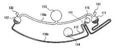
図2はプレート10の形状と各部の名称を示し、図3はプレート10の緩衝剤と生体サンプルの動きを示している。 FIG. 2 shows the shape of the
図3Aにおいて、使用者がプレート10の緩衝剤注入口123に緩衝剤を、生体サンプル注入口124に生体サンプルをそれぞれ注入した後、生体サンプル判別装置にセットする。 In FIG. 3A, the user injects a buffer into the
プレート10を充填用モータ21によって回転すると、図3Bの状態で緩衝剤は緩衝剤注入部113から2つに分かれ第1の流路116aを通り電極挿入部121、122、にいたる。一方の生体サンプルは生体サンプル注入部114から第2の流路117に保持される。 When the
そのまま回転を続けることにより図3Cの状態になる。2つに分かれた緩衝剤は電極挿入部121、122から第1の流路116bを通り、第1の流路116と第2の流路117が共通する部分、すなわち定量部120で交わり保持される。生体サンプルはこの状態を保持したままである。 By continuing the rotation as it is, the state of FIG. 3C is obtained. The two buffering agents pass from the
次に図3Dでは生体サンプル注入口124に加圧ポンプ52からの空気を送ることで、生体サンプルを第1の流路116と第2の流路117が共通する部分、すなわち定量部120を通り、生体サンプルプール115まで充填する。 Next, in FIG. 3D, by sending air from the
その後もう一度、充填用モータ21を使ってプレート10を回転することで、図3Eの第1の流路116と第2の流路117が共通する部分、すなわち定量部120にのみ生体サンプルが残る。 After that, by rotating the
この直後第1の流路116と第2の流路117が共通する部分を光学検出器40で検出し、きちんと定量部120にのみ生体サンプルが保持された状態、すなわち定量された状態になっているかを検出する。 Immediately after this, a portion where the
生体サンプルが定量部に存在しない場合は、生体サンプルが第2の定量部にまで流れ込んでいなかったり、定量部以外の第1の流路116に生体サンプルが流れ込んでしまったりして、きちんと定量できていない可能性があるため、分析動作を中止する。 If the biological sample does not exist in the quantification unit, the biological sample has not flowed into the second quantification unit, or the biological sample has flowed into the
なお、本実施の形態では緩衝剤と生体サンプルを注入し、回転動作により充填させる例を説明したが、プレートを回転することなく、生体サンプルの輸送反応を検出し判別する装置において、第1の流路に緩衝剤を充填し、第2の流路に生体サンプルを充填し、第1の流路と第2の流路が共通する部分、すなわち定量部で生体サンプルを定量化した直後に、光学検出器で検出することによって、分析動作の続行・中止を判断することも同様である。 In the present embodiment, the buffer agent and the biological sample are injected and filled by the rotation operation. However, in the apparatus for detecting and discriminating the transport reaction of the biological sample without rotating the plate, Immediately after filling the flow path with a buffer, filling the second flow path with a biological sample, and quantifying the biological sample in the portion where the first flow path and the second flow path are common, that is, the quantification unit, It is the same to determine whether to continue or stop the analysis operation by detecting with an optical detector.
本発明にかかる生体サンプル判別装置は、輸送反応を検出する場合に、事前に生体サンプルの定量部を検出し輸送反応の準備が出来たどうかをみるので、輸送反応の検出の失敗を未然に防ぐことができるものであり、微細な流路を用いた液体試料の判別装置に用いて有用である。 When detecting a transport reaction, the biological sample discriminating apparatus according to the present invention detects the quantification part of the biological sample in advance and checks whether the transport reaction is ready. Therefore, it is useful for a liquid sample discriminating apparatus using a fine channel.
10 プレート
20 充填ユニット
21 充填用モータ
21a プレート受け部
22 プレートトレイ
23 プレート確認センサ
30 検出ユニット
31 嵌合ピン
32 電気泳動用電極
32a,32b 電極
33 ヒータ
34 加圧部
36 クランパ
37 天井板
38 低速回転モータ
39,142 サーミスタ
40 光学検出部
41c 圧電素子
42 距離測定部
50 昇降ステージ
51 上下動モータ
52 加圧ポンプ部
53 ポンプチューブ
54 装置内温度検出センサ
55 ヒータ温度検出センサ
60 筺体
61 扉
62 電源スイッチ
63 LED
64 冷却ファン
65a,65b ゴム脚
66 高圧電源
67 装置電源
68 制御基板
69a 邪魔板
100 生体サンプル判別装置
110 パターン
111 第1の電極部
112 第2の電極部
113 緩衝剤の注入部
114 生体サンプルの注入部
115 サンプルプール
116 第1の流路
116a 内周流路
116b 外周流路
117 第2の流路
118 第1の電極待機孔
119 第2の電極待機孔
121,122 電極挿入口
123 緩衝剤の注入口
124 生体サンプルの注入口
131,132,135 空気孔DESCRIPTION OF
DESCRIPTION OF
64
Claims (7)
Translated fromJapanese前記プレートの第1の流路に緩衝剤を充填させた後に、前記定量部を含む前記第2の流路に前記生体サンプルを充填させる充填ユニットと、前記定量部に存在するサンプルを、前記緩衝剤中で移動させ、緩衝剤中を移動する前記生体サンプルを判別する判別ユニットとを備える生体サンプル判別装置において、
前記装置は、さらに、前記定量部に対して光照射する発光部と、前記定量部からの光を受光する受光部とからなる光学ユニットを備え、
前記第2の流路に前記生体サンプルを充填させて、生体サンプルの定量を行った後に、前記定量部に生体サンプルが存在するか否かを、前記光学ユニットで検出するようにしたことを特徴とする生体サンプル判別装置。A first flow channel into which a buffering agent flows, and a part of the flow channel, the first flow channel and a part of the flow channel being in common, and a fixed amount unit holding a certain amount of biological sample; And a second channel through which the biological sample is introduced into the channel including a plate having a channel pattern formed thereon,
After filling the first flow path of the plate with a buffering agent, the filling unit that fills the second flow path including the quantification unit with the biological sample, and the sample present in the quantification part In a biological sample discriminating apparatus comprising a discriminating unit that discriminates the biological sample that moves in the agent and moves in the buffer,
The apparatus further includes an optical unit including a light emitting unit that emits light to the quantitative unit, and a light receiving unit that receives light from the quantitative unit,
After the biological sample is filled in the second flow path and the biological sample is quantified, the optical unit detects whether or not the biological sample is present in the quantification unit. A biological sample discrimination device.
Priority Applications (1)
| Application Number | Priority Date | Filing Date | Title |
|---|---|---|---|
| JP2006354297AJP2008164434A (en) | 2006-12-28 | 2006-12-28 | Biological sample discrimination device |
Applications Claiming Priority (1)
| Application Number | Priority Date | Filing Date | Title |
|---|---|---|---|
| JP2006354297AJP2008164434A (en) | 2006-12-28 | 2006-12-28 | Biological sample discrimination device |
Publications (1)
| Publication Number | Publication Date |
|---|---|
| JP2008164434Atrue JP2008164434A (en) | 2008-07-17 |
Family
ID=39694137
Family Applications (1)
| Application Number | Title | Priority Date | Filing Date |
|---|---|---|---|
| JP2006354297APendingJP2008164434A (en) | 2006-12-28 | 2006-12-28 | Biological sample discrimination device |
Country Status (1)
| Country | Link |
|---|---|
| JP (1) | JP2008164434A (en) |
Cited By (6)
| Publication number | Priority date | Publication date | Assignee | Title |
|---|---|---|---|---|
| JP2012506027A (en)* | 2008-10-14 | 2012-03-08 | サムスン エレクトロニクス カンパニー リミテッド | Centrifugal force-based microfluidic device and sample analysis method using the microfluidic device |
| US10309976B2 (en) | 2014-06-30 | 2019-06-04 | Phc Holdings Corporation | Substrate for sample analysis, sample analysis device, sample analysis system, and program for sample analysis system |
| US10520521B2 (en) | 2014-06-30 | 2019-12-31 | Phc Holdings Corporation | Substrate for sample analysis, sample analysis device, sample analysis system, and program for sample analysis system |
| US10539583B2 (en) | 2014-12-12 | 2020-01-21 | Phc Holdings Corporation | Substrate for sample analysis, sample analysis device, sample analysis system, and program for sample analysis system |
| US10539582B2 (en) | 2014-06-30 | 2020-01-21 | Phc Holdings Corporation | Substrate for sample analysis, sample analysis device, sample analysis system, and method for removing liquid from liquid that contains magnetic particles |
| US10539560B2 (en) | 2014-06-30 | 2020-01-21 | Phc Holdings Corporation | Substrate for sample analysis, and sample analysis apparatus |
- 2006
- 2006-12-28JPJP2006354297Apatent/JP2008164434A/enactivePending
Cited By (6)
| Publication number | Priority date | Publication date | Assignee | Title |
|---|---|---|---|---|
| JP2012506027A (en)* | 2008-10-14 | 2012-03-08 | サムスン エレクトロニクス カンパニー リミテッド | Centrifugal force-based microfluidic device and sample analysis method using the microfluidic device |
| US10309976B2 (en) | 2014-06-30 | 2019-06-04 | Phc Holdings Corporation | Substrate for sample analysis, sample analysis device, sample analysis system, and program for sample analysis system |
| US10520521B2 (en) | 2014-06-30 | 2019-12-31 | Phc Holdings Corporation | Substrate for sample analysis, sample analysis device, sample analysis system, and program for sample analysis system |
| US10539582B2 (en) | 2014-06-30 | 2020-01-21 | Phc Holdings Corporation | Substrate for sample analysis, sample analysis device, sample analysis system, and method for removing liquid from liquid that contains magnetic particles |
| US10539560B2 (en) | 2014-06-30 | 2020-01-21 | Phc Holdings Corporation | Substrate for sample analysis, and sample analysis apparatus |
| US10539583B2 (en) | 2014-12-12 | 2020-01-21 | Phc Holdings Corporation | Substrate for sample analysis, sample analysis device, sample analysis system, and program for sample analysis system |
Similar Documents
| Publication | Publication Date | Title |
|---|---|---|
| US9213043B2 (en) | Clinical diagnostic system including instrument and cartridge | |
| US7939032B2 (en) | Microchip processing apparatus | |
| JP4938082B2 (en) | Cleaning device, suction nozzle clogging detection method, and automatic analyzer | |
| JP2008164434A (en) | Biological sample discrimination device | |
| AU2013262815A1 (en) | Clinical diagnostic system including instrument and cartridge | |
| JP4646809B2 (en) | Biological sample discrimination device, biological sample discrimination method, and biological sample discrimination plate | |
| JP6130306B2 (en) | Rapid quantification of biomolecules and methods in selectively functionalized nanofluidic biosensors | |
| JP7033668B2 (en) | Automatic analysis system | |
| CA2623782A1 (en) | An automated system for continuously and automatically calibrating electrochemical sensors | |
| JP2007114192A (en) | Liquid level detector | |
| JPWO2007132631A1 (en) | Cleaning device and automatic analyzer | |
| EP2136210A1 (en) | Body fluid sample analyzer | |
| JP2007322394A (en) | Dispensing device and automated analyzer | |
| JP6617374B2 (en) | Liquid feeding method, liquid feeding device and analyzer | |
| JP4720419B2 (en) | Separation buffer solution filling apparatus for microchip and microchip processing apparatus having the same | |
| JP2007107915A (en) | Electrophoresis method in capillary channel and microchip processing apparatus | |
| JPWO2007132632A1 (en) | Cleaning device and automatic analyzer | |
| JPWO2008096563A1 (en) | Microchip inspection system, microchip inspection apparatus and program | |
| JPWO2020090283A1 (en) | Method and detection device for detecting abnormal detection | |
| CN109195706B (en) | Device for analysis of a fluid sample | |
| WO2019038427A1 (en) | Analyser for fluid sample analysis | |
| JP2007086036A (en) | Apparatus and method for detecting property change of liquid | |
| CN116930294A (en) | Electrolyte analysis device, sample analyzer, and control method | |
| US20180275154A1 (en) | Cartridge, detecting device, and detecting method | |
| JP2008249542A (en) | Clinical analyzer |