JP2008157446A - Driving force transmission mechanism between two or more rotary shafts, and oil-free fluid machine using the driving force transmission mechanism - Google Patents
Driving force transmission mechanism between two or more rotary shafts, and oil-free fluid machine using the driving force transmission mechanismDownload PDFInfo
- Publication number
- JP2008157446A JP2008157446AJP2007301155AJP2007301155AJP2008157446AJP 2008157446 AJP2008157446 AJP 2008157446AJP 2007301155 AJP2007301155 AJP 2007301155AJP 2007301155 AJP2007301155 AJP 2007301155AJP 2008157446 AJP2008157446 AJP 2008157446A
- Authority
- JP
- Japan
- Prior art keywords
- driving force
- force transmission
- transmission mechanism
- gear
- rotating shafts
- Prior art date
- Legal status (The legal status is an assumption and is not a legal conclusion. Google has not performed a legal analysis and makes no representation as to the accuracy of the status listed.)
- Pending
Links
Images


Classifications
- F—MECHANICAL ENGINEERING; LIGHTING; HEATING; WEAPONS; BLASTING
- F04—POSITIVE - DISPLACEMENT MACHINES FOR LIQUIDS; PUMPS FOR LIQUIDS OR ELASTIC FLUIDS
- F04C—ROTARY-PISTON, OR OSCILLATING-PISTON, POSITIVE-DISPLACEMENT MACHINES FOR LIQUIDS; ROTARY-PISTON, OR OSCILLATING-PISTON, POSITIVE-DISPLACEMENT PUMPS
- F04C29/00—Component parts, details or accessories of pumps or pumping installations, not provided for in groups F04C18/00 - F04C28/00
- F04C29/0042—Driving elements, brakes, couplings, transmissions specially adapted for pumps
- F04C29/005—Means for transmitting movement from the prime mover to driven parts of the pump, e.g. clutches, couplings, transmissions
- F—MECHANICAL ENGINEERING; LIGHTING; HEATING; WEAPONS; BLASTING
- F04—POSITIVE - DISPLACEMENT MACHINES FOR LIQUIDS; PUMPS FOR LIQUIDS OR ELASTIC FLUIDS
- F04C—ROTARY-PISTON, OR OSCILLATING-PISTON, POSITIVE-DISPLACEMENT MACHINES FOR LIQUIDS; ROTARY-PISTON, OR OSCILLATING-PISTON, POSITIVE-DISPLACEMENT PUMPS
- F04C25/00—Adaptations of pumps for special use of pumps for elastic fluids
- F04C25/02—Adaptations of pumps for special use of pumps for elastic fluids for producing high vacuum
- F—MECHANICAL ENGINEERING; LIGHTING; HEATING; WEAPONS; BLASTING
- F04—POSITIVE - DISPLACEMENT MACHINES FOR LIQUIDS; PUMPS FOR LIQUIDS OR ELASTIC FLUIDS
- F04C—ROTARY-PISTON, OR OSCILLATING-PISTON, POSITIVE-DISPLACEMENT MACHINES FOR LIQUIDS; ROTARY-PISTON, OR OSCILLATING-PISTON, POSITIVE-DISPLACEMENT PUMPS
- F04C29/00—Component parts, details or accessories of pumps or pumping installations, not provided for in groups F04C18/00 - F04C28/00
- F04C29/0042—Driving elements, brakes, couplings, transmissions specially adapted for pumps
- F04C29/005—Means for transmitting movement from the prime mover to driven parts of the pump, e.g. clutches, couplings, transmissions
- F04C29/0064—Magnetic couplings
Landscapes
- Engineering & Computer Science (AREA)
- Mechanical Engineering (AREA)
- General Engineering & Computer Science (AREA)
- Applications Or Details Of Rotary Compressors (AREA)
- Compressors, Vaccum Pumps And Other Relevant Systems (AREA)
- Rotary Pumps (AREA)
- Details And Applications Of Rotary Liquid Pumps (AREA)
- Gear Transmission (AREA)
- Connection Of Motors, Electrical Generators, Mechanical Devices, And The Like (AREA)
- General Details Of Gearings (AREA)
Abstract
Description
Translated fromJapanese本発明は、2軸以上の回転軸間の駆動力伝達機構と該駆動力伝達機構を用いた流体ポンプ(無給油流体機械)に係り、特に、2軸以上の回転軸を有する、例えばルーツ型、スクリュー型、クロー型などと呼ばれる機械式ドライ真空ポンプなどにおける、各軸の回転同期とトルク伝達を確実におこないながら、各軸に動力を伝達するギアに潤滑油を使わずにオイル汚染を防止した、2軸以上の回転軸間の駆動力伝達機構と該駆動力伝達機構を用いた無給油流体機械に関するものである。 The present invention relates to a driving force transmission mechanism between two or more rotating shafts and a fluid pump (oil-free fluid machine) using the driving force transmitting mechanism, and particularly, for example, a roots type having two or more rotating shafts. Prevents oil contamination without using lubricating oil in the gears that transmit power to each shaft while reliably synchronizing rotation and torque transmission in mechanical dry vacuum pumps called screw type, claw type, etc. The present invention relates to a driving force transmission mechanism between two or more rotating shafts and an oil-free fluid machine using the driving force transmission mechanism.
真空ポンプのような流体ポンプには、例えば複数の繭型ロータ(回転子)がケーシング内で高速回転して空気を排出するルーツ型、複数のスクリュー(ネジ)型のロータを回転させながらケーシングとの間に閉じこめた空気を圧縮し、排出するようにしたスクリュー型、複数の爪に似た突起を有したロータが同じくケーシング内で回転して空気を排出するクロー型など、2軸以上の回転軸を有するポンプが存在する。 A fluid pump such as a vacuum pump includes, for example, a root type in which a plurality of vertical rotors (rotors) rotate at high speed in a casing to discharge air, and a casing while rotating a plurality of screw (screw) type rotors. Rotating more than two axes, such as a screw type that compresses and discharges the air trapped in between, and a claw type in which a rotor with projections similar to multiple claws rotates in the casing and discharges air There are pumps with shafts.
こういった2軸以上の回転軸を有する機械式ドライ真空ポンプでは、各軸の回転位相(同期)や中心を常に正確に維持する必要があるため、金属製のギアが使われることが多い。この金属製のギアは、歯が破損しない限り正確に同期を保ちながら駆動力を伝達できるが、摩耗が起こるため、オイル、グリース、固体潤滑剤などを用いた潤滑が必要であり、他にも熱を持ったり騒音が大きい等の問題がある。 In such a mechanical dry vacuum pump having two or more rotation axes, it is necessary to always maintain the rotation phase (synchronization) and the center of each axis accurately, so that a metal gear is often used. This metal gear can transmit the driving force while maintaining accurate synchronization as long as the teeth are not damaged, but wear occurs, so lubrication with oil, grease, solid lubricant, etc. is necessary. There are problems such as heat and loud noise.
このうち、オイル、グリース、固体潤滑剤などを用いた潤滑では、オイルはドライ真空ポンプにおける真空の性能を悪くし、低速の場合はグリースが使用できるが補充がしづらい。固体潤滑剤は大きな負荷には不向きであり、グリースとこの固体潤滑剤は熱を取り去ることが難しい。そのためギア室に潤滑油を溜めておき、運転時に各部への潤滑を行なうようにしているものがあるが、上記したように潤滑油により潤滑を行なうと、ロータに対する回転導入部の軸シールからの油の洩れや、オイルシールからポンプ室への潤滑油の洩れ、そして洩れた油による後段の排気系の汚れなどの問題が生じる。 Among these, in lubrication using oil, grease, solid lubricant, etc., the oil deteriorates the vacuum performance in the dry vacuum pump, and grease can be used at low speed but is difficult to replenish. Solid lubricants are unsuitable for heavy loads, and grease and this solid lubricant are difficult to remove heat. For this reason, some oil is stored in the gear chamber so that each part is lubricated during operation. However, as described above, when lubrication is performed with the lubricating oil, the shaft from the shaft seal of the rotation introduction part with respect to the rotor is used. Problems such as oil leakage, leakage of lubricating oil from the oil seal to the pump chamber, and contamination of the exhaust system in the subsequent stage due to the leaked oil occur.
そのため、樹脂歯車を用いたり、歯付きのベルトを用い、無潤滑で駆動力を伝達することも考えられるが、これらでは金属歯車に比較して弱いため、大きなトルクを伝達できないという問題があると共に、寿命にも問題がある。 Therefore, it is conceivable to use a plastic gear or a toothed belt and transmit the driving force without lubrication, but these are weak compared to metal gears, and there is a problem that a large torque cannot be transmitted. There is also a problem with the lifetime.
そのため特許文献1には、ルーツ型の機械式ドライ真空ポンプにおいて、駆動モータの駆動軸と一方のまゆ型インペラー(ロータ)の軸とにそれぞれ環状マグネットを対向させて取付け、両環状マグネット間にポンプ室側を大気側から遮蔽する電気的絶縁材料から成る密閉板部材を配置し、また二つのまゆ型インペラーを互いに逆方向に回転連動させるギアを金属製ギアと合成樹脂製ギアとの組合わせで構成して、回転駆動力導入部の気密性並びに回転軸の軸受及びギヤ部の潤滑油の洩れ、及び回転軸のまわりのオイルシール等による摩擦に基く動作温度の上昇や起動トルクの損失を改善することが示されている。 Therefore, in Patent Document 1, in a roots-type mechanical dry vacuum pump, an annular magnet is attached to each of a drive shaft of a drive motor and a shaft of one eyebrows type impeller (rotor), and the pump is interposed between both annular magnets. A sealing plate member made of an electrically insulating material that shields the chamber side from the atmosphere side is arranged, and a gear that rotates and links the two eyebrows type impellers in opposite directions is a combination of a metal gear and a synthetic resin gear. Constructed to improve the airtightness of the rotational drive force introduction part, leakage of lubricating oil in the bearing and gear part of the rotating shaft, and increase in operating temperature and loss of starting torque due to friction caused by oil seals around the rotating shaft Has been shown to do.
しかしながら、この特許文献1に示されたルーツ型の機械式ドライ真空ポンプは、駆動モータからの駆動力を環状マグネットによって伝達しているが、このようにするとモータを高速回転させる場合、同期が外れてモータの回転をまゆ型インペラー(ロータ)の軸に正確に伝えられない可能性がある。これを防ぐために強力な磁石を用いると、駆動モータからの駆動力は環状マグネットを介して直接、金属歯車、または樹脂歯車に伝えられているから、樹脂歯車に大きな力が加わって破損する可能性があり、破損を免れたとしても、寿命に問題が生じる。 However, the roots-type mechanical dry vacuum pump disclosed in Patent Document 1 transmits the driving force from the driving motor by an annular magnet. However, when the motor is rotated at a high speed, the synchronization is lost. The rotation of the motor may not be accurately transmitted to the eyebrows type impeller (rotor) shaft. If a strong magnet is used to prevent this, the driving force from the drive motor is directly transmitted to the metal gear or resin gear via the annular magnet, so there is a possibility that the resin gear will be damaged by applying a large force. Even if it is free from damage, there will be a problem with the service life.
そのため本発明においては、互いに平行に設けられた2軸以上の回転軸を有し、互いの回転軸間で回転の同期を取りながら無潤滑で駆動力の伝達も正確に行い、それによってオイルによる汚染を防止し、かつ、寿命的にも問題を生じないようにした、駆動力伝達機構と該駆動力伝達機構を用いた無給油流体機械を提供することが課題である。 Therefore, in the present invention, it has two or more rotating shafts provided in parallel to each other, and accurately transmits the driving force without lubrication while synchronizing the rotation between the rotating shafts. It is an object to provide a driving force transmission mechanism and an oil-free fluid machine using the driving force transmission mechanism that prevents contamination and does not cause a problem in life.
上記課題を解決するため本発明になる2軸以上の回転軸間の駆動力伝達機構は、
互いに平行に設けられた2軸以上の回転軸を有し、一の回転軸から他の回転軸へ駆動力を伝える2軸以上の回転軸間の駆動力伝達機構であって、
ギアと、複数の磁石を非磁性体からなる支持体の周方向に配してなる磁石板を固定し、前記他の回転軸に、前記ギアと噛合する他のギアと、複数の磁石を周方向に配した非磁性体からなる他の支持体を固定して、前記ギアにおける少なくとも一のギアを樹脂で形成し、
前記2軸以上の回転軸における回転同期を前記噛合したギアで、前記回転軸間の駆動力の伝達を、それぞれの支持体に固定した前記磁石同士が引き合いと反発を順次繰り返すことで行うことを特徴とする。In order to solve the above problems, the driving force transmission mechanism between two or more rotating shafts according to the present invention is:
A driving force transmission mechanism between two or more rotating shafts having two or more rotating shafts provided in parallel to each other and transmitting a driving force from one rotating shaft to another rotating shaft,
A gear and a magnet plate in which a plurality of magnets are arranged in a circumferential direction of a support made of a non-magnetic material are fixed, and another gear meshing with the gear and a plurality of magnets are wound around the other rotating shaft. Fixing another support made of a non-magnetic material arranged in the direction, and forming at least one of the gears with a resin;
Rotation synchronization of the two or more rotating shafts is performed by the meshed gears, and transmission of the driving force between the rotating shafts is performed by sequentially repeating the attracting and repelling between the magnets fixed to the respective supports. Features.
また、該駆動力伝達機構を用いた無給油流体機械は、
ケーシングと、該ケーシング内に各々の回転軸によって回転可能に取り付けられた2以上のロータとからなり、前記2以上のロータが協働して前記ケーシング内の気体を含む流体を排出する無給油流体機械において、
前記一のロータの回転軸に駆動源の駆動軸を結合すると共に、ギアと、複数の磁石を周方向に配した非磁性体からなる支持体を固定し、前記他のロータの回転軸に、前記ギアと噛合する他のギアと、複数の磁石を周方向に配した非磁性体からなる他の支持体を固定して、前記ギアにおける少なくとも一のギアを樹脂で形成した駆動力伝達機構を用い、
前記2以上のロータにおける回転同期を前記駆動力伝達機構における噛合したギアで、前記回転軸間の駆動力伝達を、前記駆動力伝達機構におけるそれぞれの支持体に配した前記磁石同士が引き合いと反発を順次繰り返すことで行うことを特徴とする。An oil-free fluid machine using the driving force transmission mechanism is
An oil-free fluid comprising a casing and two or more rotors rotatably mounted in the casing by respective rotating shafts, wherein the two or more rotors cooperate to discharge a fluid containing gas in the casing In the machine
A drive shaft of a drive source is coupled to the rotation shaft of the one rotor, and a gear and a support made of a non-magnetic material in which a plurality of magnets are arranged in the circumferential direction are fixed, and the rotation shaft of the other rotor is A driving force transmission mechanism in which another gear meshing with the gear and another support made of a non-magnetic material in which a plurality of magnets are arranged in the circumferential direction are fixed, and at least one of the gears is formed of resin. Use
Rotation synchronization in the two or more rotors is engaged with a gear in the driving force transmission mechanism, and the driving force transmission between the rotating shafts is attracted and repelled by the magnets arranged on respective supports in the driving force transmission mechanism. It is characterized by performing by repeating sequentially.
このように駆動力伝達機構を、周方向に複数の磁石を配した非磁性体からなる支持体とよりなる磁石板を各回転軸の一端に取付け、互いに噛合するギアを各回転軸の他端に取り付けて構成することで、まず、回転軸間の駆動力伝達の一部を磁石板を介して行うことができ、残りをギアにより行うようにできる。そうすることにより、ギアに大きな力を掛けることなく駆動力を伝達できるから、樹脂製のギアを用いることができるので潤滑油は不要となり寿命が長くなる。従って、このように構成した駆動力伝達機構を無給油流体機械に用いれば、潤滑油によるオイル汚染を防止し、機械式ドライ真空ポンプなどの無給油流体機械の高性能化を実現することができる。 As described above, the driving force transmission mechanism is attached to one end of each rotating shaft with a magnet plate made of a nonmagnetic support having a plurality of magnets arranged in the circumferential direction, and a gear meshing with each other is connected to the other end of each rotating shaft. First, a part of the driving force transmission between the rotating shafts can be performed via the magnet plate, and the rest can be performed by the gear. By doing so, since the driving force can be transmitted without applying a large force to the gear, a resin gear can be used, so that no lubricating oil is required and the life is extended. Therefore, if the driving force transmission mechanism configured as described above is used in an oil-free fluid machine, it is possible to prevent oil contamination due to the lubricating oil and to achieve high performance of the oil-free fluid machine such as a mechanical dry vacuum pump. .
そして、前記ギアは前記回転軸の一端側に、磁石を配した支持体は前記回転軸の他端側にそれぞれ固定し、駆動力の伝達と同期を回転軸の両端に分けて行うことで、バランスの良い駆動力伝達機構とすることができる。 Then, the gear is fixed to one end of the rotating shaft, and the support having the magnet is fixed to the other end of the rotating shaft, and the transmission and synchronization of the driving force are performed separately at both ends of the rotating shaft. A well-balanced driving force transmission mechanism can be obtained.
また、前記ギアは、前記駆動源の駆動軸を結合した側とは逆側に固定することで、ギアの摩耗による交換なども容易に行うことができる。 Further, the gear can be easily exchanged due to wear of the gear by fixing the gear to the side opposite to the side where the drive shaft of the drive source is coupled.
さらに、前記磁石を前記支持体における側面に配し、前記各支持体は、該支持体の各側面に配した磁石が互いに接触せずに対面するよう前記ロータの回転軸に固定されていることで、駆動力を伝達する磁石同士をより近接させることができ、それだけ、駆動力の伝達を確実に行うことができる。 Further, the magnet is disposed on a side surface of the support body, and each support body is fixed to the rotating shaft of the rotor so that the magnets disposed on each side surface of the support body face each other without contacting each other. Thus, the magnets that transmit the driving force can be brought closer to each other, and the driving force can be reliably transmitted accordingly.
以上記載のごとく、本発明になる2軸以上の回転軸間の駆動力伝達機構は、駆動力の伝達が磁石板及びギアの2つの方法で行われることによりギアにかかる負荷が軽減され樹脂製歯車を用いることができる。その結果無潤滑とすることができ、オイルによる汚染を防止しながら長寿命を実現することができる。よって、機械式ドライ真空ポンプなどの無給油流体機械において高性能化を実現することができる。 As described above, the driving force transmission mechanism between two or more rotating shafts according to the present invention reduces the load applied to the gear by transmitting the driving force by two methods of the magnet plate and the gear. Gears can be used. As a result, non-lubrication can be achieved, and a long life can be achieved while preventing contamination by oil. Therefore, high performance can be realized in an oil-free fluid machine such as a mechanical dry vacuum pump.
以下、図面を参照して本発明の好適な実施例を例示的に詳しく説明する。但しこの実施例に記載されている構成部品の形状、その相対的配置等は特に特定的な記載がない限りは、この発明の範囲をそれに限定する趣旨ではなく、単なる説明例に過ぎない。 Hereinafter, exemplary embodiments of the present invention will be described in detail with reference to the drawings. However, as long as there is no specific description, the shape of the component described in this embodiment, its relative arrangement, and the like are not intended to limit the scope of the present invention, but are merely illustrative examples.
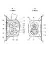
図1は、本発明になる2軸以上の回転軸間の駆動力伝達機構を用いた流体ポンプ(無給油流体機械)としての、ルーツ型機械式ドライ真空ポンプにおける、(A)が上面図、(B)が正面図、(C)が側面図である。また、図2(A)はこの図1(A)におけるA−A位置の断面図であり、(B)は同じくC−C位置の断面図である。なお、以下の説明では、本発明を上記したルーツ型機械式ドライ真空ポンプに適用した場合を例に説明するが、本発明になる駆動力伝達機構は、基本的に互いに平行に設けられた2軸以上の回転軸を有し、互いの回転軸間で回転の同期を取りながら無潤滑でトルク伝達を行い、かつ、長寿命を望む機器であればどのような機器であっても適用可能であり、また、真空ポンプにおいても、前記したスクリュー型、クロー型などにも適用することができる。 FIG. 1 is a top view of a roots type mechanical dry vacuum pump as a fluid pump (oil-free fluid machine) using a driving force transmission mechanism between two or more rotating shafts according to the present invention. (B) is a front view and (C) is a side view. 2A is a cross-sectional view taken along the line AA in FIG. 1A, and FIG. 2B is a cross-sectional view taken along the line CC. In the following description, the case where the present invention is applied to the above-described roots type mechanical dry vacuum pump will be described as an example. However, the driving force transmission mechanisms according to the present invention are basically provided in parallel with each other. It can be applied to any equipment that has more than one axis and transmits torque without lubrication while synchronizing the rotation between each axis, and that requires a long service life. In addition, the vacuum pump can also be applied to the above-described screw type, claw type, and the like.
図1において10は無給油流体機械としてのルーツ型機械式ドライ真空ポンプであり、11はこの真空ポンプ10を駆動する駆動源たるモータ、12はモータ11の駆動軸、13はモータ11の駆動軸12を真空ポンプにおける一の回転軸14と結合するためのジョイント、15は真空ポンプにおける他の回転軸、16、17は、後記するようにモータ11から一の回転軸14に伝えられた駆動力を他の回転軸15に伝えるため、円盤状に形成した支持体162、172における側面の周方向に複数の磁石161、171を略等間隔に配した磁石板で、この磁石板16、17は、配した磁石が接触しないよう互いに対面させてそれぞれの回転軸14、15に固定されている。ジョイント13を介して磁石板16に伝達されたモータ11の駆動力は、後記するように磁性力により磁石板17に伝達される。支持体162、172はアルミや銅、ステンレス、あるいは樹脂などの非磁性体を用いて作られている。18、19は回転軸14、15の他端に取り付けて回転軸14、15を確実に同期させながら回転させるためのギア、20は真空ポンプ10、モータ11を固定するための基台、21、22はこの基台20に真空ポンプ10、モータ11を固定する固定手段、25、26(図2B参照)は吸気口と排気口である。 In FIG. 1, 10 is a roots type mechanical dry vacuum pump as an oil-free fluid machine, 11 is a motor as a drive source for driving the
真空ポンプ10は、図2(B)に示したように、外形が略長方形をしたケーシング100のポンプ室101には、互いに平行になるように図示しないオイルレスベアリングで支持される回転軸14、15に3葉ローブロータ102、103が一体化して取り付けられている。ロータ102、103は互いに接触しないよう、また頂部がポンプ室101の円弧部の内壁に僅かの隙間を保つように回転する。 As shown in FIG. 2 (B), the
この2つのロータ102、103が例えば矢印27方向に同期して回転することで、空気などの流体はロータのローブで囲まれた空間104に捉えられて、吸気口25側から、排気口26側に運ばれて排出されることとなる。 By rotating these two
再度図1を参照して、このように構成された真空ポンプ10は、基台20に固定手段21によって固定され、同じく基台20に固定手段22で固定されたモータ11の駆動軸12と、回転軸14とがジョイント13で結合される。そしてその駆動軸14のモータ11側には、アルミニウムや銅、ステンレス、あるいは樹脂などの非磁性体を用い、円盤状に形成した支持体162の側面の周方向に複数の磁石を略等間隔に配した磁石板16が固定され、また、この駆動軸14の逆側の端にはギア18が固定される。 Referring again to FIG. 1, the
一方、回転軸14と平行に設けられた回転軸15には、モータ11側に磁石板16と同様、非磁性体で円盤状に形成した支持体172の側面の周方向に、前記磁石板16に配された磁石と接触することなく対面するよう複数の磁石171が略等間隔に配された磁石板17が固定され、さらに回転軸15の逆側端には、前記ギア18と噛合するギア19が固定されている。 On the other hand, the rotating
そして本発明になる駆動力伝達機構では、この噛合するギア18または19の少なくともどちらか一方を樹脂製、他方を樹脂製または金属製とし、樹脂製のギアを用いることで潤滑を不要とした。また、磁石板16、17は、図1(A)のA−A位置における断面図である図2(A)に示したように、円盤状の支持体162、172の周方向に複数の磁石161、171が配されている。 In the driving force transmission mechanism according to the present invention, at least one of the meshing gears 18 and 19 is made of resin, the other is made of resin or metal, and lubrication is unnecessary by using a resin gear. Moreover, as shown in FIG. 2 (A) which is a cross-sectional view at the position AA in FIG. 1 (A), the
このように構成した真空ポンプ10における駆動力伝達機構のみを取り出して示したのが図3である。この図3において(A)は駆動軸14、15方向に対して直角な方向から見た側面図である。図3Aから判るように、磁石161、171は支持体162、172の片面に配置されまたこの磁石161、171が互いに接触せずに対面するよう支持板162、172が回転軸14、15に固定されている。(B)は歯車18、19方向から見た図で、いずれも中間に設けられた真空ポンプ部分を省略してある。 FIG. 3 shows only the driving force transmission mechanism in the
繰り返しになるがこの図3において、磁石板16に配された磁石161と磁石板17の磁石171が接触することなく対面するように回転軸14、15に固定されており、回転軸14、15のが反対方向に回転することにより次々と磁石161、171が対面するようになっている。 Again, in FIG. 3, the
回転軸14に磁石板16の反対側に取り付けられたギア18が回転軸15に磁石板15の反対側に取り付けられたギア19と噛合することにより回転軸14、15が相互反対方向に回転する。回転軸14に固定された磁石板16は駆動モータ11により回転すると、磁石板17は後記するように磁石161、171間の相互作用により反対方向へ回転する。回転軸14が駆動モータ11で回転すると、磁石板16、17及びギア18、19を介して回転軸15に駆動力が伝達されることになる。よって前記したように、噛合するギア18または19の少なくともどちらか一方を樹脂製、他方が樹脂製または金属製として樹脂製のギアを用いることで潤滑を不要とすることができる。 When the
図4は、この磁石板16、17によって駆動力を伝達する様子を説明するための概念図である。今、例えば図4(A)に示したように、支持板40に磁石N41、S42、N43、S44が、支持板45に磁石S46、N47、S48、N49がそれぞれ図のように配され、両支持板40、45は静止しているとすると、磁石N41と磁石S46とが50で示した矢印のように引き合うことになる。 FIG. 4 is a conceptual diagram for explaining how the driving force is transmitted by the
この状態で、例えば図4(B)に51で示した矢印方向に磁石板40が回転すると、磁石N41と磁石S46が50のように引き合ったまま、今度は徐々に磁石44と磁石46との間に反発力が生じ、この磁石同士の引き合う力と反発する力が順次繰り返されることで、磁石板45が磁石板40の回転に追随して回転する。そのため磁石板45は、磁石板40と無接触で回転することになる。 In this state, for example, when the
この支持板45を回転させる力は、当然のことながら支持板40、45に固定されている磁石41、42、43、44と、磁石46、47、48、49とが近接していれば近接しているほど強くなる。従って、図2(A)や図3(A)に示したように、磁石板16に配された磁石161と磁石板17に配された磁石171とが、接触することなく対面するよう支持板162と172とを回転軸14、15に固定すれば、支持板172(すなわち回転軸15)を回転させる力は大きくなる。 As a matter of course, the force for rotating the
しかしながら、このように構成した駆動力伝達機構では、例えば図4に示した支持板45を固定した回転軸に大きな負荷がある場合、支持板45が回転しなかったり同期が外れてしまう場合がある。 However, in the driving force transmission mechanism configured as described above, for example, when there is a large load on the rotating shaft to which the
そのため本発明においては、回転軸14、15の同期を前記した互いに噛合したギア18、19で行い、駆動力の伝達を回転軸14、15に固定した磁石板16,17をメインとして行うようにしたもので、例えば、磁石板16,17に駆動力伝達力の70%程度を受け持たせ、ギア18、19には、駆動力伝達力の30%程度がかかるようにした。 Therefore, in the present invention, the
このようにすることにより、まず、2以上の回転軸14、15における回転同期をさせるギア18、19の負荷を減少させる。また、ギアのうちの少なくとも1つを樹脂製にしてギアの寿命を減少させ、潤滑油を不要とする。樹脂製ギアを上記したように使用することにより、樹脂製のギアを用いることで大きなトルクが伝達できない問題と、寿命が短くなる問題とを同時に解決することができる。 In this way, first, the loads on the
従って、このように構成した駆動力伝達機構を無給油流体機械に用いれば、まず潤滑油によるオイル汚染が防止でき、軸間の駆動力も確実に伝達できるから、前記した2軸以上の回転軸を有する機械式ドライ真空ポンプなどの無給油流体機械の高性能化を実現することができる。また、ギア18、19をモータ11とは逆側に設けたことで、ギア18、19のうち、樹脂製のギアが摩耗したり破損した場合も、容易に交換が可能となる。 Therefore, if the driving force transmission mechanism configured in this way is used in an oil-free fluid machine, firstly, oil contamination due to lubricating oil can be prevented and the driving force between the shafts can be reliably transmitted. High performance of an oil-free fluid machine such as a mechanical dry vacuum pump can be realized. Further, since the
このように本発明によれば、駆動力伝達機構を互いに噛合したギア18、19と、周方向に複数の磁石161、171を略等間隔に配した非磁性体からなる支持体162、172とから成る磁石板16,17で構成したことで、駆動伝達の一部は磁石板により行うことができ残りをギアで行う。そうすると、樹脂製ギアに大きな力を掛けることなく駆動力を伝達できるから、樹脂製のギアを用いることができ、ギアの潤滑油は不要となりギアの寿命が長くなる。
従って、このように構成した駆動力伝達機構を無給油流体機械に用いれば、潤滑油によるオイル汚染を防止し、機械式ドライ真空ポンプなどの無給油流体機械の高性能化を実現することができる。As described above, according to the present invention, the
Therefore, if the driving force transmission mechanism configured as described above is used in an oil-free fluid machine, it is possible to prevent oil contamination due to the lubricating oil and to achieve high performance of the oil-free fluid machine such as a mechanical dry vacuum pump. .
本発明によれば、潤滑油を用いないにもかかわらず大きな駆動力を伝達できる寿命の長い駆動力伝達機構を提供でき、この駆動力伝達機構を真空ポンプに用いることで、オイル汚染のない、高性能な真空ポンプを提供することができる。 According to the present invention, it is possible to provide a long-life driving force transmission mechanism that can transmit a large driving force without using lubricating oil, and by using this driving force transmission mechanism for a vacuum pump, there is no oil contamination. A high-performance vacuum pump can be provided.
10 真空ポンプ
100 ケーシング
101 ポンプ室
102、103 ロータ
104 凹状部
11 モータ
12 駆動軸
13 ジョイント
14 一の回転軸
15 他の回転軸
16、17 磁石板
161、171 磁石
162、172 支持板
18、19 ギア
20 基台
21、22 固定手段
25、26 吸気(または排気)口、排気(または吸気)口
40、45 支持板
41、42、43、44、46、47、48、49 磁石
50 磁石の引き合い方向
51 支持板40の回転方向DESCRIPTION OF
Claims (6)
Translated fromJapanese回転軸に、ギアと、複数の磁石を非磁性体からなる支持体の周方向に配して成る磁石板を固定し、前記他の回転軸に、前記ギアと噛合する他のギアと、複数の磁石を周方向に配した非磁性体からなる他の支持体を固定して、前記ギアにおける少なくとも一のギアを樹脂で形成し、
前記2軸以上の回転軸における回転同期を前記噛合したギアで、前記回転軸間の駆動力の伝達を、それぞれの支持体に固定した前記磁石同士が引き合いと反発を順次繰り返すことで行うことを特徴とする2軸以上の回転軸間の駆動力伝達機構。A driving force transmission mechanism between two or more rotating shafts having two or more rotating shafts provided in parallel to each other and transmitting a driving force from one rotating shaft to another rotating shaft,
A gear plate and a magnet plate in which a plurality of magnets are arranged in the circumferential direction of a support made of a non-magnetic material are fixed to the rotation shaft, and another gear meshing with the gear is connected to the other rotation shaft, Fixing another support made of a non-magnetic material with the magnets arranged in the circumferential direction, and forming at least one of the gears with a resin,
Rotation synchronization of the two or more rotating shafts is performed by the meshed gears, and transmission of the driving force between the rotating shafts is performed by sequentially repeating the attracting and repelling between the magnets fixed to the respective supports. A driving force transmission mechanism between two or more rotating shafts.
ギアと、複数の磁石を非磁性体からなる支持体の周方向に配してなる磁石板を各ロータの回転軸に固定し、また相互に噛合するギアをそれぞれのロータの回転軸に取り付けて、前記ギアにおける少なくとも一のギアを樹脂で形成した駆動力伝達機構を用い、
前記2以上のロータにおける回転同期を前記駆動力伝達機構における噛合したギアで、前記回転軸間の駆動力伝達を、前記駆動力伝達機構におけるそれぞれの支持体に配した前記磁石同士が引き合いと反発を順次繰り返すことで行うことを特徴とする無給油流体機械。An oil-free fluid comprising a casing and two or more rotors rotatably mounted in the casing by respective rotating shafts, wherein the two or more rotors cooperate to discharge a fluid containing gas in the casing In the machine
A gear and a magnet plate in which a plurality of magnets are arranged in the circumferential direction of a support made of a non-magnetic material are fixed to the rotation shaft of each rotor, and gears that mesh with each other are attached to the rotation shaft of each rotor. , Using a driving force transmission mechanism in which at least one of the gears is made of resin,
Rotation synchronization in the two or more rotors is engaged with a gear in the driving force transmission mechanism, and the driving force transmission between the rotating shafts is attracted and repelled by the magnets arranged on respective supports in the driving force transmission mechanism. An oil-free fluid machine characterized by sequentially repeating the steps.
Priority Applications (1)
| Application Number | Priority Date | Filing Date | Title |
|---|---|---|---|
| JP2007301155AJP2008157446A (en) | 2006-11-30 | 2007-11-21 | Driving force transmission mechanism between two or more rotary shafts, and oil-free fluid machine using the driving force transmission mechanism |
Applications Claiming Priority (2)
| Application Number | Priority Date | Filing Date | Title |
|---|---|---|---|
| JP2006323960 | 2006-11-30 | ||
| JP2007301155AJP2008157446A (en) | 2006-11-30 | 2007-11-21 | Driving force transmission mechanism between two or more rotary shafts, and oil-free fluid machine using the driving force transmission mechanism |
Publications (1)
| Publication Number | Publication Date |
|---|---|
| JP2008157446Atrue JP2008157446A (en) | 2008-07-10 |
Family
ID=39113999
Family Applications (1)
| Application Number | Title | Priority Date | Filing Date |
|---|---|---|---|
| JP2007301155APendingJP2008157446A (en) | 2006-11-30 | 2007-11-21 | Driving force transmission mechanism between two or more rotary shafts, and oil-free fluid machine using the driving force transmission mechanism |
Country Status (4)
| Country | Link |
|---|---|
| US (1) | US7578665B2 (en) |
| EP (1) | EP1927757A1 (en) |
| JP (1) | JP2008157446A (en) |
| CN (1) | CN101245784A (en) |
Cited By (2)
| Publication number | Priority date | Publication date | Assignee | Title |
|---|---|---|---|---|
| JP2012127271A (en)* | 2010-12-15 | 2012-07-05 | Isuzu Motors Ltd | Engine vibration reducing device |
| JP2021513023A (en)* | 2018-02-02 | 2021-05-20 | 中山市天元真空設備技術有限公司Zhongshan Tianyuan Vacuum Equipment Technology Co., Ltd. | Multi-stage roots type dry vacuum pump |
Families Citing this family (51)
| Publication number | Priority date | Publication date | Assignee | Title |
|---|---|---|---|---|
| JP2008138549A (en)* | 2006-11-30 | 2008-06-19 | Anest Iwata Corp | Oilless fluid machine having oilless fluid machine body provided with two or more rotating shafts |
| JP4807318B2 (en)* | 2007-05-09 | 2011-11-02 | トヨタ自動車株式会社 | Power transmission device |
| US8760251B2 (en) | 2010-09-27 | 2014-06-24 | Correlated Magnetics Research, Llc | System and method for producing stacked field emission structures |
| US8174347B2 (en) | 2010-07-12 | 2012-05-08 | Correlated Magnetics Research, Llc | Multilevel correlated magnetic system and method for using the same |
| US8115581B2 (en) | 2008-04-04 | 2012-02-14 | Correlated Magnetics Research, Llc | Techniques for producing an electrical pulse |
| US8760250B2 (en) | 2009-06-02 | 2014-06-24 | Correlated Magnetics Rsearch, LLC. | System and method for energy generation |
| US8373527B2 (en) | 2008-04-04 | 2013-02-12 | Correlated Magnetics Research, Llc | Magnetic attachment system |
| US8279032B1 (en) | 2011-03-24 | 2012-10-02 | Correlated Magnetics Research, Llc. | System for detachment of correlated magnetic structures |
| US9202616B2 (en) | 2009-06-02 | 2015-12-01 | Correlated Magnetics Research, Llc | Intelligent magnetic system |
| US7800471B2 (en) | 2008-04-04 | 2010-09-21 | Cedar Ridge Research, Llc | Field emission system and method |
| US8368495B2 (en) | 2008-04-04 | 2013-02-05 | Correlated Magnetics Research LLC | System and method for defining magnetic structures |
| US9105380B2 (en) | 2008-04-04 | 2015-08-11 | Correlated Magnetics Research, Llc. | Magnetic attachment system |
| US9371923B2 (en) | 2008-04-04 | 2016-06-21 | Correlated Magnetics Research, Llc | Magnetic valve assembly |
| US8816805B2 (en) | 2008-04-04 | 2014-08-26 | Correlated Magnetics Research, Llc. | Magnetic structure production |
| US7843295B2 (en) | 2008-04-04 | 2010-11-30 | Cedar Ridge Research Llc | Magnetically attachable and detachable panel system |
| US8179219B2 (en) | 2008-04-04 | 2012-05-15 | Correlated Magnetics Research, Llc | Field emission system and method |
| US8779879B2 (en) | 2008-04-04 | 2014-07-15 | Correlated Magnetics Research LLC | System and method for positioning a multi-pole magnetic structure |
| US8648681B2 (en) | 2009-06-02 | 2014-02-11 | Correlated Magnetics Research, Llc. | Magnetic structure production |
| US9202615B2 (en) | 2012-02-28 | 2015-12-01 | Correlated Magnetics Research, Llc | System for detaching a magnetic structure from a ferromagnetic material |
| US7868721B2 (en)* | 2008-04-04 | 2011-01-11 | Cedar Ridge Research, Llc | Field emission system and method |
| EP2274706A1 (en)* | 2008-04-04 | 2011-01-19 | Cedar Ridge Research, Llc | Techniques for producing an electrical pulse |
| US8576036B2 (en) | 2010-12-10 | 2013-11-05 | Correlated Magnetics Research, Llc | System and method for affecting flux of multi-pole magnetic structures |
| US20100176674A1 (en)* | 2009-01-14 | 2010-07-15 | Richard Freeman Post | Gear Trains Employing Magnetic Coupling |
| US8937521B2 (en) | 2012-12-10 | 2015-01-20 | Correlated Magnetics Research, Llc. | System for concentrating magnetic flux of a multi-pole magnetic structure |
| US8917154B2 (en) | 2012-12-10 | 2014-12-23 | Correlated Magnetics Research, Llc. | System for concentrating magnetic flux |
| US9257219B2 (en) | 2012-08-06 | 2016-02-09 | Correlated Magnetics Research, Llc. | System and method for magnetization |
| US8704626B2 (en) | 2010-05-10 | 2014-04-22 | Correlated Magnetics Research, Llc | System and method for moving an object |
| US9404776B2 (en) | 2009-06-02 | 2016-08-02 | Correlated Magnetics Research, Llc. | System and method for tailoring polarity transitions of magnetic structures |
| US9275783B2 (en) | 2012-10-15 | 2016-03-01 | Correlated Magnetics Research, Llc. | System and method for demagnetization of a magnetic structure region |
| US9711268B2 (en) | 2009-09-22 | 2017-07-18 | Correlated Magnetics Research, Llc | System and method for tailoring magnetic forces |
| WO2011037845A2 (en) | 2009-09-22 | 2011-03-31 | Cedar Ridge Research, Llc. | Multilevel correlated magnetic system and method for using same |
| JP4981152B2 (en)* | 2010-04-20 | 2012-07-18 | トヨタ自動車株式会社 | Vehicle oil pump |
| US8638016B2 (en) | 2010-09-17 | 2014-01-28 | Correlated Magnetics Research, Llc | Electromagnetic structure having a core element that extends magnetic coupling around opposing surfaces of a circular magnetic structure |
| US8279031B2 (en) | 2011-01-20 | 2012-10-02 | Correlated Magnetics Research, Llc | Multi-level magnetic system for isolation of vibration |
| US8702437B2 (en) | 2011-03-24 | 2014-04-22 | Correlated Magnetics Research, Llc | Electrical adapter system |
| US9330825B2 (en) | 2011-04-12 | 2016-05-03 | Mohammad Sarai | Magnetic configurations |
| US8963380B2 (en) | 2011-07-11 | 2015-02-24 | Correlated Magnetics Research LLC. | System and method for power generation system |
| US9219403B2 (en) | 2011-09-06 | 2015-12-22 | Correlated Magnetics Research, Llc | Magnetic shear force transfer device |
| US8848973B2 (en) | 2011-09-22 | 2014-09-30 | Correlated Magnetics Research LLC | System and method for authenticating an optical pattern |
| DE102012003066B3 (en)* | 2012-02-17 | 2013-07-04 | Netzsch Pumpen & Systeme Gmbh | METHOD AND DEVICE FOR FIXING AND SYNCHRONIZING TURNING PISTONS IN A ROTARY PISTON PUMP |
| US9245677B2 (en) | 2012-08-06 | 2016-01-26 | Correlated Magnetics Research, Llc. | System for concentrating and controlling magnetic flux of a multi-pole magnetic structure |
| US20140072439A1 (en)* | 2012-09-07 | 2014-03-13 | Graham James Luker | Tri-lobe flowmeter rotor with partially open core structure |
| US8951012B1 (en)* | 2014-02-10 | 2015-02-10 | JVS Associates, Inc. | Contra-rotating axial fan transmission for evaporative and non-evaporative cooling and condensing equipment |
| US9298281B2 (en) | 2012-12-27 | 2016-03-29 | Correlated Magnetics Research, Llc. | Magnetic vector sensor positioning and communications system |
| US9490666B1 (en)* | 2016-01-20 | 2016-11-08 | Thomas Alexander Zummo | Magnetic energy converter |
| DE102016120579B3 (en)* | 2016-10-27 | 2018-04-05 | Klaus Union Gmbh & Co. Kg | Horizontally split screw pump |
| CN106678040A (en)* | 2017-03-08 | 2017-05-17 | 太仓顺达磁力泵科技有限公司 | Hydrogen circulation pump for hydrogen fuel cell system |
| DE102018210922A1 (en)* | 2018-07-03 | 2020-01-09 | Leybold Gmbh | Dual or multi-shaft vacuum pump |
| CN109441810A (en)* | 2018-12-10 | 2019-03-08 | 江阴爱尔姆真空设备有限公司 | A kind of oil-free dry screw vacuum pump |
| CN112208249A (en)* | 2020-10-30 | 2021-01-12 | 泉州市一扬文化用品有限公司 | Magnetic transmission mechanism of correction tape |
| CN116044747A (en)* | 2023-02-01 | 2023-05-02 | 无锡威孚高科技集团股份有限公司 | A Roots type fluid pump |
Citations (3)
| Publication number | Priority date | Publication date | Assignee | Title |
|---|---|---|---|---|
| JPS6217390A (en)* | 1985-06-25 | 1987-01-26 | スペクトラ−フイジツクス・インコ−ポレイテツド | Sealed rotary compressor |
| JPH08317629A (en)* | 1995-05-18 | 1996-11-29 | Nec Corp | Magnetic power transmission device |
| JP2002139107A (en)* | 2000-09-15 | 2002-05-17 | Heidelberger Druckmas Ag | Conduction gear stage and varnishing unit having the same |
Family Cites Families (10)
| Publication number | Priority date | Publication date | Assignee | Title |
|---|---|---|---|---|
| US3150593A (en)* | 1961-04-24 | 1964-09-29 | Waukesha Foundry Co | Metering pump |
| JPS6185483A (en) | 1984-10-04 | 1986-05-01 | Toyoda Gosei Co Ltd | Adhesive composition |
| US4717322A (en)* | 1986-08-01 | 1988-01-05 | Toyota Jidosha Kabushiki Kaisha | Roots-type fluid machine |
| EP0290662B1 (en)* | 1987-05-15 | 1993-03-31 | Leybold Aktiengesellschaft | Positive-displacement two-shaft vacuum pump |
| JPH02153285A (en) | 1988-12-05 | 1990-06-12 | Ebara Corp | Screw fluid machine |
| JPH06185483A (en) | 1991-12-02 | 1994-07-05 | Shinku Kiko Kk | Dry mechanical booster pump |
| SE501889C2 (en) | 1993-10-18 | 1995-06-12 | Opcon Autorotor Ab | Device for coupling a screw rotor machine to a driving or driven pulley |
| KR100346820B1 (en)* | 1994-04-21 | 2002-11-30 | 가부시키 가이샤 에바라 세이사꾸쇼 | Multi-axis electric motors and combined volume vacuum pumps |
| DE10019066A1 (en)* | 2000-04-18 | 2001-10-25 | Leybold Vakuum Gmbh | Vacuum pump with two cooperating rotors has drive shaft with drive pulley engaging directly with take-off hear on rotor shaft to form transmission stage |
| JP2008138549A (en)* | 2006-11-30 | 2008-06-19 | Anest Iwata Corp | Oilless fluid machine having oilless fluid machine body provided with two or more rotating shafts |
- 2007
- 2007-11-21JPJP2007301155Apatent/JP2008157446A/enactivePending
- 2007-11-26EPEP07022876Apatent/EP1927757A1/ennot_activeWithdrawn
- 2007-11-28USUS11/946,218patent/US7578665B2/ennot_activeExpired - Fee Related
- 2007-11-30CNCNA2007101691312Apatent/CN101245784A/enactivePending
Patent Citations (3)
| Publication number | Priority date | Publication date | Assignee | Title |
|---|---|---|---|---|
| JPS6217390A (en)* | 1985-06-25 | 1987-01-26 | スペクトラ−フイジツクス・インコ−ポレイテツド | Sealed rotary compressor |
| JPH08317629A (en)* | 1995-05-18 | 1996-11-29 | Nec Corp | Magnetic power transmission device |
| JP2002139107A (en)* | 2000-09-15 | 2002-05-17 | Heidelberger Druckmas Ag | Conduction gear stage and varnishing unit having the same |
Cited By (3)
| Publication number | Priority date | Publication date | Assignee | Title |
|---|---|---|---|---|
| JP2012127271A (en)* | 2010-12-15 | 2012-07-05 | Isuzu Motors Ltd | Engine vibration reducing device |
| JP2021513023A (en)* | 2018-02-02 | 2021-05-20 | 中山市天元真空設備技術有限公司Zhongshan Tianyuan Vacuum Equipment Technology Co., Ltd. | Multi-stage roots type dry vacuum pump |
| JP7121416B2 (en) | 2018-02-02 | 2022-08-18 | 中山市天元真空設備技術有限公司 | Multistage roots type dry vacuum pump |
Also Published As
| Publication number | Publication date |
|---|---|
| US20080181804A1 (en) | 2008-07-31 |
| EP1927757A1 (en) | 2008-06-04 |
| US7578665B2 (en) | 2009-08-25 |
| CN101245784A (en) | 2008-08-20 |
Similar Documents
| Publication | Publication Date | Title |
|---|---|---|
| JP2008157446A (en) | Driving force transmission mechanism between two or more rotary shafts, and oil-free fluid machine using the driving force transmission mechanism | |
| JP2008138549A (en) | Oilless fluid machine having oilless fluid machine body provided with two or more rotating shafts | |
| WO2016184417A1 (en) | Miniature turbocharger | |
| CN102734163A (en) | Air compressor | |
| JP2015169177A (en) | Oil-free screw compressor | |
| JP2024507620A (en) | Compressor and air conditioner | |
| JPWO2019026340A1 (en) | Vacuum pump | |
| JPH06185483A (en) | Dry mechanical booster pump | |
| JP2008115747A (en) | Electric pump | |
| JP6240229B2 (en) | Vacuum pump | |
| JP2010180932A (en) | Sealing structure for one-way clutch | |
| CN116324223A (en) | Reducers and Robots | |
| TW202225563A (en) | Dry vacuum pump | |
| US20120062079A1 (en) | Rotor for Motor | |
| CN103958929B (en) | gear transmission | |
| JP4194582B2 (en) | Low wear rotating structure | |
| JP2007211639A (en) | Oil-free screw compressor | |
| JPS60116892A (en) | Screw type vacuum pump | |
| CN200978961Y (en) | Thin oil self-operated machine sealing device | |
| JP6430722B2 (en) | CAND MOTOR AND VACUUM PUMP HAVING THE SAME | |
| JP2006138210A (en) | Hermetic electric compressor | |
| JP4356375B2 (en) | Compressor | |
| TW202438767A (en) | Dry vacuum pump | |
| JP2005180313A (en) | Compressor | |
| JP2003042086A (en) | Dry vacuum pump |
Legal Events
| Date | Code | Title | Description |
|---|---|---|---|
| A621 | Written request for application examination | Free format text:JAPANESE INTERMEDIATE CODE: A621 Effective date:20101101 | |
| A977 | Report on retrieval | Free format text:JAPANESE INTERMEDIATE CODE: A971007 Effective date:20111124 | |
| A131 | Notification of reasons for refusal | Free format text:JAPANESE INTERMEDIATE CODE: A131 Effective date:20120330 | |
| RD02 | Notification of acceptance of power of attorney | Free format text:JAPANESE INTERMEDIATE CODE: A7422 Effective date:20120406 | |
| A02 | Decision of refusal | Free format text:JAPANESE INTERMEDIATE CODE: A02 Effective date:20120731 |