JP2008156180A - Glass plate scribing method and glass plate scribing device - Google Patents
Glass plate scribing method and glass plate scribing deviceDownload PDFInfo
- Publication number
- JP2008156180A JP2008156180AJP2006349084AJP2006349084AJP2008156180AJP 2008156180 AJP2008156180 AJP 2008156180AJP 2006349084 AJP2006349084 AJP 2006349084AJP 2006349084 AJP2006349084 AJP 2006349084AJP 2008156180 AJP2008156180 AJP 2008156180A
- Authority
- JP
- Japan
- Prior art keywords
- glass plate
- glass
- scribe
- plate
- scribing
- Prior art date
- Legal status (The legal status is an assumption and is not a legal conclusion. Google has not performed a legal analysis and makes no representation as to the accuracy of the status listed.)
- Granted
Links
- 239000011521glassSubstances0.000title2
Images


Landscapes
- Processing Of Stones Or Stones Resemblance Materials (AREA)
- Re-Forming, After-Treatment, Cutting And Transporting Of Glass Products (AREA)
Abstract
Description
Translated fromJapanese本発明はガラス板を切断するためガラス板にスクライブ線を入れるガラス板スクライブ方法、およびそのガラス板スクライブ方法をおこなうガラス板スクライブ装置に関する。 The present invention relates to a glass plate scribing method for putting a scribe line into a glass plate for cutting the glass plate, and a glass plate scribing apparatus for performing the glass plate scribing method.
液晶ディスプレイ、プラズマディスプレイなどのフラットパネルディスプレイ用ガラス板は、製板工程にて成形された連続するガラス板を粗切断してガラス原板を得て、続くガラス板切断工程にて所定の寸法の長方形に加工されてフラットパネルディスプレイ用のガラス基板が得られる。 Glass plates for flat panel displays such as liquid crystal displays and plasma displays are obtained by roughly cutting a continuous glass plate formed in the plate making process to obtain a glass original plate, followed by a rectangular plate having a predetermined size in the glass plate cutting step. To obtain a glass substrate for a flat panel display.
ガラス板切断工程は次のとおりである。まずガラス板スクライブ装置により、ダイヤモンドまたは超硬材からなるガラスカッタを取り付けたスクライブヘッドを、ガラス原板表面上で移動させて、ガラス原板表面にスクライブ線を入れる。次にガラス板折割装置にて、スクライブ線に沿ってガラス原板に曲げ応力を加えることにより機械的に折割りガラス元板を得る。ガラス元板の折割り面はシャープなため危険であり、また折割り面近傍には微小クラックや欠けなどの欠陥がある。そのため次いでガラス板端面研削装置にて、回転砥石によりガラス元板の端面を端面研削して折割り面を滑らかにするとともに、欠陥部分を除去することによりガラス基板を得る。 The glass plate cutting process is as follows. First, a scribe head to which a glass cutter made of diamond or super hard material is attached is moved on the surface of the glass original plate by a glass plate scribe device, and a scribe line is put on the surface of the glass original plate. Next, a glass breaker is mechanically obtained by applying bending stress to the glass original plate along the scribe line. Since the split surface of the glass base plate is sharp, it is dangerous, and there are defects such as microcracks and chips near the split surface. Therefore, in the glass plate end face grinding apparatus, the end face of the glass base plate is subjected to end face grinding with a rotating grindstone to smooth the split surface, and a defective portion is removed to obtain a glass substrate.
ガラス基板の形状としては四隅が90°の角度からなる正確な長方形(以後四隅が全て90°の正確な長方形を、単に長方形と呼ぶことにする)が求められる。そのためには四辺が正確に直交する四本のスクライブ線を入れ、四辺を均一に端面研削し、長方形のガラス板を得ることが理想である。 The shape of the glass substrate is required to be an accurate rectangle having four corners of 90 ° (hereinafter, an exact rectangle having all four corners of 90 ° is simply referred to as a rectangle). For that purpose, it is ideal to insert four scribe lines whose four sides are exactly orthogonal, and to uniformly grind the four sides to obtain a rectangular glass plate.
特許文献1に記載のガラス原板の切断装置(ガラス板スクライブ装置)は、平行な2本のガイド手段上を走行するスライド部材上に架設された走行体(ビーム)にビーム走行方向のカッタ(スクライブヘッド)を備え、さらに走行体(ビーム)上を走行するスライダ走行方向のカッタ(スクライブヘッド)を備える。このときガイド手段と走行体が直交するように調整できれば、ビーム走行方向、スライダ走行方向のスクライブ線は直交するので、長方形のスクライブ線を入れることができる。
ガラス原板から効率良くガラス基板として仕上げるためには、ガラス元板の折割り面を滑らかにし欠陥を除去するために必要な最小限の研削代だけ研削するようにすればよい。ガラス板スクライブ装置においては、ガラス原板表面上に入れる四辺のスクライブ線が正確に直交するように、ガラス板スクライブ装置の一対のスライド部材が走行する一対のレールの平行度および、一対のスライド部材に架設されたビームと前記レールとの直角度を正しく調整することが重要である。このためガラス板スクライブ装置は熟練した技術者が長時間かけて調整する必要がある。 In order to efficiently finish the glass substrate as a glass substrate, it is only necessary to grind only the minimum grinding allowance necessary for smoothing the broken surface of the glass base plate and removing defects. In the glass plate scribe device, the parallelism of the pair of rails that the pair of slide members of the glass plate scribe device travels and the pair of slide members so that the four scribe lines put on the glass original plate surface are exactly orthogonal It is important to correctly adjust the perpendicularity between the erected beam and the rail. For this reason, the glass plate scribing apparatus needs to be adjusted over time by a skilled engineer.
しかも近年、ガラス基板の一辺が2mを越えて大きくなり、ガラス板スクライブ装置自体も大型化しており、ガラス板スクライブ装置の調整が一層困難になってきている。 Moreover, in recent years, one side of the glass substrate has become larger than 2 m, and the glass plate scribing apparatus itself has also become larger, making it difficult to adjust the glass plate scribing apparatus.
また、ガラス板スクライブ装置の一対のスライド部材が走行する一対のレールの平行度および、一対のスライド部材に架設されたビームと前記レールとの直角度を正しく調整しても、スクライブ線を入れ、スクライブ線に沿って折割りした後、端面研削したガラス基板が、規格範囲内ではあるものの四隅の直角度が出ず長方形からずれた形状の四角形になることがある。この場合、削り残りが生じないように研削代を大きめに取らざるを得ず、その結果研削時間が長くなってしまう。フラットパネルディスプレイ用のガラス基板の大板化により、研削代を大きく取らなければならない傾向が顕著になってきている。In addition, even if the parallelism of the pair of rails on which the pair of slide members of the glass plate scribe device runs and the perpendicularity between the beam and the rails laid on the pair of slide members are correctly adjusted, a scribe line is inserted, After being broken along the scribe line, the end-ground glass substrate may become a quadrangle having a shape deviating from the rectangle because the squareness of the four corners is not within the standard range. In this case, a large grinding allowance must be taken so as not to leave a shaving, resulting in a long grinding time. With the increase in the size of glass substrates for flat panel displays, the tendency to require a large grinding allowance has become prominent.
本発明のガラス板スクライブ方法、ガラス板スクライブ装置の目的は、研削代を少なくして研削時間を短縮することである。そのために研削線の四辺にそれぞれ平行で研削代だけ大きい形状のスクライブ線を設定する。またそのことを可能にするガラス板スクライブ方法を提供し、またガラス板の大型化に対応して調整が容易なガラス板スクライブ装置を提供する。The purpose of the glass plate scribing method and glass plate scribing apparatus of the present invention is to reduce the grinding time by reducing the grinding allowance. Therefore, a scribe line having a shape that is parallel to the four sides of the grinding line and that is larger by the grinding allowance is set. Moreover, the glass plate scribing method which makes it possible is provided, and the glass plate scribing apparatus which is easy to adjust corresponding to the enlargement of a glass plate is provided.
請求項1に記載の本発明のガラス板スクライブ方法は、製板工程にて成形された連続するガラス板を粗切断して得られるガラス原板の表面にガラス板スクライブ装置にてスクライブ線を入れ、次にガラス板折割装置にて前記ガラス原板を前記スクライブ線に沿って折割ってガラス元板を作製し、次にガラス板端面研削装置にて前記ガラス元板の折割り面を端面研削してガラス基板を得る一連のガラス板の切断工程での、前記ガラス原板表面にスクライブ線を入れるガラス板スクライブ方法において、ガラス板端面研削装置にて端面研削されたガラス基板の外形をなす四角形の外側に、研削代の距離だけ離れて前記四角形の各辺と平行する4本の線をスクライブ線として設定することを特徴とする。 The glass plate scribing method of the present invention according to claim 1, puts a scribe line in a glass plate scribing device on the surface of a glass original plate obtained by roughly cutting a continuous glass plate formed in the plate making step, Next, the glass original plate is broken along the scribe line by a glass plate breaking device to produce a glass base plate, and then the glass plate end face grinding device is used to end-grind the split surface of the glass original plate. In the glass plate scribing method in which a scribe line is put on the surface of the glass original plate in a series of glass plate cutting steps to obtain a glass substrate, the outside of the rectangle that forms the outer shape of the glass substrate that has been edge-ground by the glass plate end face grinding device In addition, four lines that are separated by a grinding allowance distance and parallel to each side of the quadrangle are set as scribe lines.
請求項1に記載のガラス板スクライブ方法により、研削線で囲まれた長方形のガラス基板、ないしは長方形からずれた形状の四角形のガラス基板を得る場合に、それぞれ研削線に平行するスクライブ線をガラス原板に入れることができ、ガラス元板の四辺の端面研削は折割り面を滑らかにし欠陥を除去するために必要な最小限の研削代の研削だけですみ研削時間を短縮することができる。 When a rectangular glass substrate surrounded by a grinding line or a square glass substrate having a shape deviated from the rectangular shape is obtained by the glass plate scribing method according to claim 1, each of the scribe lines parallel to the grinding line is used as a glass original plate. In addition, it is possible to reduce the grinding time by grinding the end surfaces of the four sides of the glass base plate with a minimum amount of grinding necessary for smoothing the split surface and removing defects.
請求項2に記載の本発明のガラス板スクライブ装置は、製板工程にて成形された連続するガラス板を粗切断して得られるガラス原板を載せる基台と、前記基台に設けられた、または前記基台に併設する架台に設けられた一対のレールと、個別に駆動されて前記レール上を走行する一対のスライド部材と、前記一対のスライド部材間に架設されたビームと、前記ビームがその両端で前記一対のスライド部材に対し垂直軸回りにそれぞれ回転可能で、うち一端が前記スライド部材上を前記レールと直交方向に移動可能である結合部と、前記ビームに設けられた走行レール上を駆動されてビームに平行に走行するスクライブヘッドと、前記ビームに位置調整可能に取り付けられたスクライブヘッドと、ガラス板端面研削装置にて端面研削されて得られるガラス基板の外形をなす四角形の外側に、研削代の距離だけ離れて前記四角形の各辺と平行する四本の線をスクライブ線として設定する手段と、を備えたことを特徴とする。 The glass plate scribing apparatus of the present invention according to claim 2 is provided on a base on which a glass original plate obtained by roughly cutting a continuous glass plate formed in a plate making process is placed, and the base. Alternatively, a pair of rails provided on a gantry provided alongside the base, a pair of slide members that are individually driven and run on the rails, a beam laid between the pair of slide members, and the beam A connecting portion that is rotatable about a vertical axis with respect to the pair of slide members at both ends thereof, one end of which is movable on the slide member in a direction orthogonal to the rail, and a traveling rail provided on the beam Obtained by being end-ground by a scribing head driven in parallel with the beam, a scribing head attached to the beam so as to be position-adjustable, and a glass plate end-face grinding device. Outside the rectangle forming the outer shape of the glass substrate that is characterized by comprising a means for setting four lines with a distance of grinding allowance parallel to the respective sides of the rectangle as scribe line.
請求項2に記載のガラス板スクライブ装置により請求項1に記載のガラス板スクライブ方法が実現される。さらにこのガラス板スクライブ装置においては、一対のレールの平行度とレールとビームとの直角度の調整に熟練した技術者が長時間かける必要がなくなった。 The glass plate scribing method according to claim 1 is realized by the glass plate scribing device according to claim 2. Furthermore, in this glass plate scribing apparatus, it is no longer necessary for a skilled technician to adjust the parallelism of the pair of rails and the perpendicularity between the rails and the beam for a long time.
請求項3に記載の本発明のガラス板スクライブ装置は、請求項2に記載のガラス板スクライブ装置において、前記ビーム上に設けられた走行レール上を駆動されて走行するスクライブヘッドが複数であり、前記スクライブヘッドの駆動手段が個別に制御可能であることを特徴とする。The glass plate scribe device of the present invention described in claim 3 is a glass plate scribe device according to claim 2, wherein there are a plurality of scribe heads that are driven on a traveling rail provided on the beam and travel. The drive means of the scribe head can be individually controlled.
請求項3に記載のガラス板スクライブ装置により、X方向に複数のスクライブ線を同時に入れることが可能となり、スクライブ時間の短縮ができる。 According to the glass plate scribing device of the third aspect, it becomes possible to simultaneously insert a plurality of scribe lines in the X direction, and the scribe time can be shortened.
請求項4に記載の本発明のガラス板スクライブ装置は、製板工程にて成形された連続するガラス板を粗切断して得られるガラス原板を載せる基台と、前記基台に設けられた、または前記基台に併設する架台に設けられた一対のレールと、個別に駆動制御されて前記レール上を走行する二対のスライド部材と、前記二対のスライド部材間にそれぞれ1本ずつ架設された二本のビームと、前記二本のビームがそれぞれその両端で前記それぞれのスライド部材に対し垂直軸回りにそれぞれ回転可能で、うち前記二本のビームのそれぞれの一端が前記それぞれのスライド部材上を前記レールと直交方向に移動可能である結合部と、前記二本のビームのそれぞれに設けられた走行レール上を個別に駆動されて走行する二対のスクライブヘッドと、前記ビームに位置調整可能に取り付けられたスクライブヘッドと、ガラス板端面研削装置にて端面研削されて得られるガラス基板の外形をなす四角形の外側に、研削代の距離だけ離れて前記四角形の各辺と平行する四本の線をスクライブ線として設定する手段とを備えたことを特徴とする。 The glass plate scribing apparatus of the present invention according to claim 4 is provided on a base on which a glass original plate obtained by roughly cutting a continuous glass plate formed in a plate making process is placed, and the base. Alternatively, a pair of rails provided on a base attached to the base, two pairs of slide members that are individually driven and driven on the rails, and one pair between the two pairs of slide members. The two beams and the two beams can rotate around the vertical axis with respect to the respective slide members at both ends, respectively, and one end of each of the two beams is on the respective slide member. A coupling portion that is movable in a direction orthogonal to the rail, two pairs of scribe heads that are individually driven on a traveling rail provided on each of the two beams, and the bead A scribing head that is mounted on the system so that the position can be adjusted, and the sides of the rectangle that are separated by a grinding allowance distance outside the rectangle that forms the outer shape of the glass substrate obtained by end-face grinding with a glass plate end-face grinding device. And means for setting four parallel lines as scribe lines.
請求項4に記載のガラス板スクライブ装置の、二本のビームのそれぞれに設けられた走行レール上を個別に駆動されて走行する二対のスクライブヘッドにより、同時に、またX方向にレールと任意の角度で複数のスクライブ線を入れることが可能となり、スクライブ時間の短縮ができる。 The glass plate scribing device according to claim 4, wherein two pairs of scribing heads that are individually driven and run on traveling rails provided on each of the two beams simultaneously and in the X direction with the rail. Multiple scribe lines can be inserted at an angle, and the scribe time can be shortened.
本発明のガラス板スクライブ方法およびガラス板スクライブ装置により、ガラス基板の仕上がり形状に合わせて容易にスクライブ線を入れることができるので、端面研削が最小限で済みガラス板研削の効率を高くすることができる。 With the glass plate scribing method and the glass plate scribing apparatus of the present invention, scribe lines can be easily put in accordance with the finished shape of the glass substrate, so that end face grinding is minimized and the efficiency of glass plate grinding can be increased. it can.
図1は本発明のスクライブ方法の説明図である。大判のガラス原板10に入れたスクライブ線12(二点鎖線)と、スクライブ線12に沿って折割り後に端面研削にて除去される研削代13(斜線部)との関係を示す。図1は、ガラス基板14の仕上がり形状が長方形からずれた四角形の場合である。なお、研削代13(斜線部)の内側の実線11を研削線11とよぶ。FIG. 1 is an explanatory diagram of the scribing method of the present invention. The relationship between the scribe line 12 (two-dot chain line) put on the large-sized glass
図1は1枚のガラス原板10から2枚のガラス基板14を取る(2枚取り)例についての説明図である。以下の説明でも2枚取りを例にとって記述するが、本発明は1枚のガラス原板から1枚あるいは3枚以上のガラス基板14を取る場合についても同じように適用できる。 FIG. 1 is an explanatory diagram of an example in which two
請求項1に記載のガラス板スクライブ方法により、図1に示すように研削線11で囲まれた長方形からずれた形状の四角形のガラス基板14を得る場合に、研削線11に平行するスクライブ線12をガラス原板10に入れることができ、ガラス元板の四辺の端面研削は折割り面を滑らかにし欠陥を除去するために必要な最小限の研削代13の研削だけですみ研削時間を短縮することができる。The
図1ではガラス基板14が平行四辺形で表されているが、ガラス基板14が平行四辺形に限らず台形を含む不等辺四角形であってもよい。 In FIG. 1, the
また、請求項1に記載のガラス板スクライブ方法では、図6で示すように研削線63で囲まれた長方形のガラス基板64の場合でも、研削線63に平行するスクライブ線61をガラス原板10に入れることができ、ガラス元板の四辺の端面研削は折割り面を滑らかにし欠陥を除去するために必要な最小限の研削代62の研削だけですみ研削時間を短縮することができる。Further, in the glass plate scribing method according to claim 1, even in the case of a
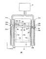
本発明のガラス板スクライブ装置を具体的に説明する。図2は本発明の第一実施例のガラス板スクライブ装置20の平面図である。Y方向にほぼ平行な一対のYスライドレール22aおよび22bを設ける。スライドレール22aおよび22b上に専用サーボモータ23a、23bによりY方向に走行するスライド部材24a、24bを設ける。左のスライド部材24aには鉛直軸を中心として自由に回転のできる首振り機構からなる結合部25aを設ける。右のスライド部材24b上にはYスライドレール22a(または22b)に直交する方向のXスライドレール26を設ける。Xスライドレール26上には、外力により受動的にX方向に走行するスライドプレート27を設ける。スライドプレート27には鉛直軸を中心にして自由に回転のできる首振り機構からなる結合部25bを設ける。左右の結合部25a、25bを結ぶビーム28を設ける。ビーム28にはX方向のスクライブ線を入れるため走行するXスクライブヘッド29と、Y方向のスクライブ線を入れるためのYスクライブヘッド30を設ける。Xスクライブヘッド29はXスクライブヘッド走行用のサーボモータ(図示せず)により駆動されるスクライブヘッドスライド部材29aに取付けられており、ビーム28に設置したビームレール28a上を走行する。Yスクライブヘッド30はビーム28に位置調整可能に取り付けられる。スライド部材24a、24b、Xスクライブヘッド29を駆動し位置決めするためにはラック・ピニオン、ボールねじ、タイミングベルト、スチールベルトなどを使用する。制御部31にはスクライブ線12x、12yの設定手段、各サーボモータ23a、23b、Xスクライブヘッド走行用のサーボモータの制御手段、Xスクライブヘッド29とYスクライブヘッド30の上下動作、スクライブ圧の制御手段が含まれる。 The glass plate scribing apparatus of the present invention will be specifically described. FIG. 2 is a plan view of the glass plate scribing
本発明の第一実施例のガラス板スクライブ装置20の動作を図2にて説明する。基台21にガラス原板10を固定し、まずY方向のスクライブ線12yを入れる。Yスクライブヘッド30を一定の圧力でガラス原板10に押しつけながら、スライド部材24a、24bをY方向に同じ速度で同じ距離だけ同期して走行するようにサーボモータ23a、23bを駆動制御する。これによりY方向のスクライブ線12yが入れられる。The operation of the glass
次にX方向のスクライブ線12xを入れる。Xスクライブヘッド29、Yスクライブヘッド30をガラス原板10から離した状態でスライド部材24a、24bを移動させ、Xスクライブヘッド29を研削線のX方向の第一の辺から研削代だけ離れた平行線の位置にもってくる。左右のスライド部材24a、24bのどちらか一方または両方のY座標をサーボモータ23a、23bで調整して、ビーム28の傾きが研削線のX方向の第一の辺の傾きと一致するようにする。Xスクライブヘッド29を一定の圧力でガラス原板10に押しつけながらビーム28上の走行レール28aに沿ってXスクライブヘッド走行用のサーボモータ(図示せず)で移動させる。これによりX方向の第一のスクライブ線12xが入れられる。Next, a
次にXスクライブヘッド29、Yスクライブヘッド30をガラス原板10から離した状態でスライド部材24a、24bを移動させ、Xスクライブヘッド29が研削線のX方向の第二の辺から研削代だけ離れた位置になるようにし、左右のスライド部材24a、24bのどちらか一方または両方のY座標をサーボモータ23a、23bで調整して、ビーム28の傾きを研削線のX方向の第二の辺の傾きと一致させる。その位置でXスクライブヘッド29を一定の圧力でガラス原板10に押しつけながら、ビーム28に沿ってXスクライブヘッド走行用のサーボモータ(図示せず)で移動させ、X方向の第二のスクライブ線12xを入れる。 Next, the
以上でY方向のスクライブ線12y、X方向のスクライブ線12xが入れられたのでスクライブ線を入れる工程は完了する。上記の説明ではY方向のスクライブ線12yを最初に入れ、次にX方向の第一のスクライブ線12x、最後にX方向の第二のスクライブ線12xを入れたが、この順序は自由に変更できる。 Since the Y-
ガラス原板10が大きくなるとガラス板スクライブ装置20も巨大となるため、一対のYスライドレール22aおよび22bの平行度、ビーム28とYスライドレール22aの角度の調整が非常に難しくなる。しかし本発明のガラス板スクライブ装置20ではスライドプレート27がスライドすることにより一対のYスライドレール22aおよび22bの平行度に誤差があっても問題にならない。またスライド部材24a、24bのY座標の位置調整によりビーム28とYスライドレール22aの直角度を容易に出すことが可能となる。 If the glass
また、ビーム28とYスライドレール22aの角度の調整が容易であることから、規格範囲内ではあるものの端面研削されたガラス基板の四隅の直角度が出ず長方形からずれた形状の四角形の各辺に平行する4本のスクライブ線を入れることが容易である。 In addition, since the angle between the
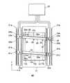
次に図3により本発明の第二実施例のガラス板スクライブ装置40を説明する。第一実施例のガラス板スクライブ装置20(図2)と共通の部分には同じ符号を付ける。図3に示すように、本発明の第二実施例のガラス板スクライブ装置40の特徴は、第一実施例のガラス板スクライブ装置20に、第二の一対のスライド部材41a、41b、第二のビーム42とビームレール42aおよび第二のXスクライブヘッド43を追加したことである。第二のXスクライブヘッド43はXスクライブヘッド走行用のサーボモータ(図示せず)により駆動されるXスクライブヘッドスライド部材43aに取付けられており、ビーム42に設置したビームレール42a上を走行する。制御部32は、追加したスライド部材41a、41bの駆動用サーボモータ41c、41d、第二のXスクライブヘッド43の上下動作、スクライブ圧およびXスクライブヘッド走行用のサーボモータ(図示せず)も制御する。第二実施例のガラス板スクライブ装置40でY方向のスクライブ線12yを入れるときは、第二のビーム42を第一のビーム28と干渉しない位置に退避させる。Y方向のスクライブ線12yを入れるときに第二のビーム42を第一のビーム28と干渉しない位置に退避させる以外の動作は第一実施例のガラス板スクライブ装置20と同じである。 Next, a glass
第二実施例のガラス板スクライブ装置40にてX方向のスクライブ線12xを入れるときは、第一のビーム28、第二のビーム42の傾きが研削線のX方向の第一の辺、第二の辺の傾きと一致するようにし、第一のXスクライブヘッド29、第二のXスクライブヘッド43がそれぞれ研削線のX方向の第一の辺、第二の辺から研削代だけ離れた位置になるように第一のビーム28、第二のビーム42の位置を調整する。ついで、第一のXスクライブヘッド29、第二のXスクライブヘッド43を一定の圧力でガラス原板10に押しつけながら、同時にそれぞれ第一のビーム28、第二のビーム42に沿ってそれぞれのXスクライブヘッド走行用のサーボモータ(図示せず)で移動させる。これにより第一のXスクライブヘッド29でX方向の第一のスクライブ線12xが、第二のXスクライブヘッド43でX方向の第二のスクライブ線12xが同時に入れられる。したがってX方向のスクライブ線12xを入れる時間を、第一実施例のガラス板スクライブ装置20に比べ半減できる。 When the
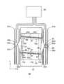
次に図4により本発明の第三実施例のガラス板スクライブ装置50を説明する。第一実施例のガラス板スクライブ装置20(図2)と共通の部分には同じ符号を付ける。Yスライドレール22a、22b、専用サーボモータ23a、23b、スライド部材24a、24b、結合部25a、25b、Xスライドレール26、スライドプレート27は第一実施例と同じ構成である。結合部25a、25bを結ぶ長方形または正方形の四辺からなる額縁形のビームを設け、これを額縁ビーム51と呼ぶことにする。第三実施例のガラス板スクライブ装置50は額縁ビーム51を備えたことが特徴である。 Next, a glass
額縁ビーム51の上下の辺にビームレール52bを設ける。上下の辺に設けたビームレール52b上をXスクライブヘッド走行用のサーボモータ(図示せず)により、X方向に走行する一対のXビームスライド部材52aにXビーム52を架設する。Xビーム52にX方向のスクライブ線12xを入れるためのXスクライブヘッド53を位置調整可能に設ける。また額縁ビーム51の上辺または下辺にY方向のスクライブ線12yを入れるためのYスクライブヘッド54を位置調整可能に設ける。制御部33にはスクライブ線12x、12yの設定手段、各サーボモータ23a、23b、Xビーム52走行用サーボモータ(図示せず)の制御手段、Xスクライブヘッド53とYスクライブヘッド54の上下動作、スクライブ圧の制御手段が含まれる。 Beam rails 52 b are provided on the upper and lower sides of the
第三実施例のガラス板スクライブ装置50の動作を説明する。まず、額縁ビーム51の傾きが研削線のX方向の辺の傾きと一致するようにスライド部材24a、24bの位置を調整する。Yスクライブヘッド54をガラス原板10から離した状態で、2個のXスクライブヘッド53を一定の圧力でガラス板に押しつけながら、Xビーム52をXビーム52走行用サーボモータ(図示せず)で移動させる。 Operation | movement of the glass
次にXスクライブヘッド53をガラス原板10から離した状態で、Yスクライブヘッド54を一定の圧力でガラス原板10に押しつけながら、スライド部材24a、24bをY方向に同じ速度で同じ距離だけ同期して走行するようにサーボモータ23a、23bを駆動制御することによりY方向のスクライブ線12yを入れる。これによりX方向のスクライブ線12xを入れる時間を、第一実施例のガラス板スクライブ装置20に比べ半減できる。 Next, in a state where the
端面研削装置のタイプによっては、ガラス板スクライブ装置およびガラス板折割装置に比べガラス板端面研削装置は単位時間あたりのガラス板処理枚数が少ない場合がある。その場合各一台のガラス板スクライブ装置およびガラス板折割装置に例えば三台のガラス板端面研削装置A、B、Cをつなぎ、折割り済みガラス元板を順次ガラス板端面研削装置A、B、Cに振り分けるようにする必要がでてくる。一般に端面研削装置で研削したガラス基板の寸法形状は、公差内ではあるが長方形からわずかにずれた四角形になっていることが多く、またその研削線の寸法形状は個々の端面研削装置に固有であることが分かってきた。従来のスクライブ線は端面研削装置A、B、Cの三種類の研削線を全て含むように研削代に余裕を見なければならなかったが、本発明のガラス板スクライブ方法では、ガラス元板を端面研削装置に供給する順序を決めてやれば、それぞれのガラス板端面研削装置に最小の研削代を設定することができる。 Depending on the type of the end surface grinding device, the glass plate end surface grinding device may have a smaller number of processed glass plates per unit time than the glass plate scribing device and the glass plate folding device. In that case, for example, three glass plate end surface grinding devices A, B, and C are connected to each one glass plate scribing device and glass plate folding device, and the glass plate end plates that have been broken are sequentially joined to the glass plate end surface grinding devices A, B. , It will be necessary to assign to C. In general, the dimensional shape of a glass substrate ground with an end surface grinding machine is often a square that is within tolerance but slightly deviated from the rectangle, and the dimensional shape of the grinding line is specific to each end face grinding machine. I know that there is. Although the conventional scribe line had to allow for the grinding allowance so that all of the three types of grinding lines A, B, and C of the end face grinding apparatus were included, in the glass plate scribe method of the present invention, If the order of supply to the end face grinding apparatus is determined, the minimum grinding allowance can be set for each glass plate end face grinding apparatus.
上記の本発明のガラス板スクライブ方法を自動化した場合を図5の工程フロー図で説明する。
(工程1)ホストコンピュータにより、これからスクライブをおこなうガラス板がスクライブ後に送られる予定のガラス板端面研削装置を指定する。
(工程2)指定したガラス板端面研削装置の研削線データをホストコンピュータからガラス板スクライブ装置に送る。
(工程3)ガラス板スクライブ装置では、受け取った研削線データをもとに、研削線の四角形の寸法形状を特定し、四角形の各辺に平行で研削代だけ離れた位置とスクライブ線の方向を計算する。
(工程4)計算したスクライブ線の方向と位置でスクライブ線を入れる。
(工程5)スクライブ線の入れられたガラス原板をガラス板折割装置に送り、スクライブ線に沿って折割りをおこなう。
(工程6)折割りされたガラス元板を指定のガラス板端面研削装置に送り端面研削をおこなう。
(工程1)〜(工程6)の全体の制御もホストコンピュータによりおこなう。この工程フローにより、自動化された本発明のガラス板スクライブ装置が実現する。The case where the glass plate scribing method of the present invention is automated will be described with reference to the process flow diagram of FIG.
(Step 1) A glass plate end surface grinding apparatus to which a glass plate to be scribed from now is sent after scribing is designated by the host computer.
(Step 2) The grinding line data of the designated glass plate end face grinding device is sent from the host computer to the glass plate scribe device.
(Step 3) The glass plate scribing device specifies the square shape of the grinding line based on the received grinding line data, and determines the position parallel to each side of the square and separated by the grinding allowance and the direction of the scribe line. calculate.
(Step 4) Insert a scribe line at the calculated direction and position of the scribe line.
(Process 5) The glass original plate in which the scribe line was put is sent to a glass plate folding apparatus, and it is broken along the scribe line.
(Step 6) The split glass base plate is fed to a designated glass plate end surface grinding device and subjected to end surface grinding.
The entire control of (Step 1) to (Step 6) is also performed by the host computer. This process flow realizes an automated glass scribing device of the present invention.
10 ガラス原板
11 研削線
12x X方向のスクライブ線
12y Y方向のスクライブ線
13 研削代
14 ガラス基板
20 ガラス板スクライブ装置
21 基台
22a、22b Yスライドレール
23a、23b サーボモータ
24a、24b スライド部材
25a、25b 結合部
26 Xスライドレール
27 スライドプレート
28 ビーム
28a ビームレール
29 Xスクライブヘッド
29a スクライブヘッドスライド部材
30 Yスクライブヘッド
31、32、33 制御部
40 ガラス板スクライブ装置
41a、41b スライド部材
41c、41d サーボモータ
42 ビーム
42a ビームレール
43 Xスクライブヘッド
43a Xスクライブヘッドスライド部材
50 ガラス板スクライブ装置
51 額縁ビーム
52 Xビーム
52a Xビームスライド部材
52b ビームレール
53 Xスクライブヘッド
54 Yスクライブヘッド
61 スクライブ線
62 研削代
63 研削線
64 ガラス基板DESCRIPTION OF
Claims (4)
Translated fromJapaneseガラス板端面研削装置にて端面研削されたガラス基板の外形をなす四角形の外側に、研削代の距離だけ離れて前記四角形の各辺と平行する4本の線をスクライブ線として設定することを特徴とするガラス板スクライブ方法。A scribing line is put on the surface of the glass original plate obtained by roughly cutting a continuous glass plate formed in the plate making process with a glass plate scribing device, and then the glass original plate is scribed with a glass plate folding device. In a series of glass plate cutting steps, a glass base plate is produced by breaking along a line, and then a glass substrate end face grinding device is used to end face grind the surface of the glass base plate to obtain a glass substrate. In the glass plate scribing method of putting a scribe line on the glass original plate surface,
Four lines parallel to each side of the rectangle are set as scribe lines on the outer side of the rectangle that forms the outer shape of the glass substrate that has been edge-ground by the glass plate end-face grinding apparatus, and are separated by a grinding allowance distance. Glass plate scribing method.
前記基台に設けられた、または前記基台に併設する架台に設けられた一対のレールと、
個別に駆動されて前記レール上を走行する一対のスライド部材と、
前記一対のスライド部材間に架設されたビームと、
前記ビームがその両端で前記一対のスライド部材に対し垂直軸回りにそれぞれ回転可能で、うち一端が前記スライド部材上を前記レールと直交方向に移動可能である結合部と、
前記ビームに設けられた走行レール上を駆動されて走行するスクライブヘッドと、
前記ビームに位置調整可能に取り付けられたスクライブヘッドと、
ガラス板端面研削装置にて端面研削されて得られるガラス基板の外形をなす四角形の外側に、研削代の距離だけ離れて前記四角形の各辺と平行する四本の線をスクライブ線として設定する手段と、を備えたことを特徴とするガラス板スクライブ装置。A base on which an original glass plate obtained by roughly cutting a continuous glass plate formed in the plate making process is placed;
A pair of rails provided on the base, or provided on a base attached to the base;
A pair of slide members that are individually driven and run on the rail;
A beam constructed between the pair of slide members;
The beam is rotatable at both ends thereof around the vertical axis with respect to the pair of slide members, and one end of the beam is movable on the slide member in a direction orthogonal to the rail; and
A scribe head that is driven and travels on a traveling rail provided in the beam;
A scribing head attached to the beam in an adjustable manner;
Means for setting four lines parallel to each side of the square as scribe lines on the outside of the quadrangle that forms the outer shape of the glass substrate obtained by end-face grinding with a glass plate end-face grinding apparatus. And a glass plate scribing device.
前記基台に設けられた、または前記基台に併設する架台に設けられた一対のレールと、
個別に駆動制御されて前記レール上を走行する二対のスライド部材と、
前記二対のスライド部材間にそれぞれ1本ずつ架設された二本のビームと、
前記二本のビームがそれぞれその両端で前記それぞれのスライド部材に対し垂直軸回りにそれぞれ回転可能で、うち前記二本のビームのそれぞれの一端が前記それぞれのスライド部材上を前記レールと直交方向に移動可能である結合部と、
前記二本のビームのそれぞれに設けられた走行レール上を個別に駆動されて走行するスクライブヘッドと、
前記ビームに位置調整可能に取り付けられたスクライブヘッドと、
ガラス板端面研削装置にて端面研削されて得られるガラス基板の外形をなす四角形の外側に、研削代の距離だけ離れて前記四角形の各辺と平行する四本の線をスクライブ線として設定する手段とを備えたことを特徴とするガラス板スクライブ装置。A base on which an original glass plate obtained by roughly cutting a continuous glass plate formed in the plate making process is placed;
A pair of rails provided on the base, or provided on a base attached to the base;
Two pairs of slide members that are individually controlled and run on the rail;
Two beams constructed one by one between the two pairs of slide members,
Each of the two beams can be rotated around a vertical axis with respect to the respective slide member at both ends thereof, and one end of each of the two beams is perpendicular to the rail on the respective slide member. A joint that is movable;
A scribing head that travels separately driven on a traveling rail provided in each of the two beams;
A scribing head attached to the beam in an adjustable manner;
Means for setting, as scribe lines, four lines parallel to each side of the quadrilateral, separated by a grinding allowance distance, on the outside of the quadrilateral forming the outer shape of the glass substrate obtained by end-face grinding with a glass plate end-face grinding apparatus And a glass plate scribing device.
Priority Applications (1)
| Application Number | Priority Date | Filing Date | Title |
|---|---|---|---|
| JP2006349084AJP4952992B2 (en) | 2006-12-26 | 2006-12-26 | Glass plate scribing method and glass plate scribing apparatus |
Applications Claiming Priority (1)
| Application Number | Priority Date | Filing Date | Title |
|---|---|---|---|
| JP2006349084AJP4952992B2 (en) | 2006-12-26 | 2006-12-26 | Glass plate scribing method and glass plate scribing apparatus |
Publications (2)
| Publication Number | Publication Date |
|---|---|
| JP2008156180Atrue JP2008156180A (en) | 2008-07-10 |
| JP4952992B2 JP4952992B2 (en) | 2012-06-13 |
Family
ID=39657533
Family Applications (1)
| Application Number | Title | Priority Date | Filing Date |
|---|---|---|---|
| JP2006349084AActiveJP4952992B2 (en) | 2006-12-26 | 2006-12-26 | Glass plate scribing method and glass plate scribing apparatus |
Country Status (1)
| Country | Link |
|---|---|
| JP (1) | JP4952992B2 (en) |
Cited By (2)
| Publication number | Priority date | Publication date | Assignee | Title |
|---|---|---|---|---|
| KR20120102675A (en)* | 2009-11-03 | 2012-09-18 | 코닝 인코포레이티드 | Laser scoring of a moving glass ribbon having a non-constant speed |
| CN111628423A (en)* | 2020-04-29 | 2020-09-04 | 煤炭科学技术研究院有限公司 | Mining explosion-proof box is with floating self-interacting pull structure and mining explosion-proof box |
Citations (1)
| Publication number | Priority date | Publication date | Assignee | Title |
|---|---|---|---|---|
| JPH08197402A (en)* | 1995-01-25 | 1996-08-06 | Mitsuboshi Daiyamondo Kogyo Kk | Polishing method and device for glass substrate |
- 2006
- 2006-12-26JPJP2006349084Apatent/JP4952992B2/enactiveActive
Patent Citations (1)
| Publication number | Priority date | Publication date | Assignee | Title |
|---|---|---|---|---|
| JPH08197402A (en)* | 1995-01-25 | 1996-08-06 | Mitsuboshi Daiyamondo Kogyo Kk | Polishing method and device for glass substrate |
Cited By (3)
| Publication number | Priority date | Publication date | Assignee | Title |
|---|---|---|---|---|
| KR20120102675A (en)* | 2009-11-03 | 2012-09-18 | 코닝 인코포레이티드 | Laser scoring of a moving glass ribbon having a non-constant speed |
| KR101630005B1 (en) | 2009-11-03 | 2016-06-13 | 코닝 인코포레이티드 | Laser scoring of a moving glass ribbon having a non-constant speed |
| CN111628423A (en)* | 2020-04-29 | 2020-09-04 | 煤炭科学技术研究院有限公司 | Mining explosion-proof box is with floating self-interacting pull structure and mining explosion-proof box |
Also Published As
| Publication number | Publication date |
|---|---|
| JP4952992B2 (en) | 2012-06-13 |
Similar Documents
| Publication | Publication Date | Title |
|---|---|---|
| JP5450964B2 (en) | Scribing apparatus and scribing method | |
| JP5173885B2 (en) | Scribing apparatus and scribing method | |
| JP5139852B2 (en) | Scribing apparatus and scribing method | |
| JP5333816B2 (en) | Glass plate cutting apparatus and method | |
| KR101786436B1 (en) | Scribing apparatus of the substrate | |
| JP5702765B2 (en) | Scribing apparatus and scribing method | |
| TW200911428A (en) | Method and apparatus for machining work by cutting tool | |
| JP2013071335A (en) | Method for dicing mother substrate | |
| KR100863438B1 (en) | Scribing device using multi-axis synchronous control and its method | |
| JP4290784B2 (en) | Glass scriber | |
| WO2014010154A1 (en) | Scribing method and scribing device | |
| TWI527674B (en) | Method and apparatus for scribing brittle material substrate | |
| JP4952992B2 (en) | Glass plate scribing method and glass plate scribing apparatus | |
| KR20070108597A (en) | Substrate scribe device and method | |
| JP2010042473A (en) | Chamfering device for hard brittle sheet | |
| CN218642633U (en) | Cutting device for substrate | |
| TWI788615B (en) | Glass-plate working apparatus | |
| KR20150012103A (en) | Grinding device for hard and brittle plate and method for measuring and compensating machining accuracy | |
| TWI492820B (en) | Rigid brittle plate chamfering device | |
| JP3192536U (en) | Substrate scribing equipment | |
| JP2005286159A (en) | Method for cutting work and cutting apparatus | |
| TW201431631A (en) | Laser cut apparatus | |
| JP2005132685A (en) | Automatic glass scriber | |
| JP2014217982A (en) | Scribe device and scribe method | |
| CN219211689U (en) | Processing equipment for processing production boards |
Legal Events
| Date | Code | Title | Description |
|---|---|---|---|
| A621 | Written request for application examination | Free format text:JAPANESE INTERMEDIATE CODE: A621 Effective date:20090910 | |
| A977 | Report on retrieval | Free format text:JAPANESE INTERMEDIATE CODE: A971007 Effective date:20110310 | |
| A131 | Notification of reasons for refusal | Free format text:JAPANESE INTERMEDIATE CODE: A131 Effective date:20110314 | |
| A521 | Written amendment | Free format text:JAPANESE INTERMEDIATE CODE: A523 Effective date:20110512 | |
| TRDD | Decision of grant or rejection written | ||
| A01 | Written decision to grant a patent or to grant a registration (utility model) | Free format text:JAPANESE INTERMEDIATE CODE: A01 Effective date:20120216 | |
| A01 | Written decision to grant a patent or to grant a registration (utility model) | Free format text:JAPANESE INTERMEDIATE CODE: A01 | |
| A61 | First payment of annual fees (during grant procedure) | Free format text:JAPANESE INTERMEDIATE CODE: A61 Effective date:20120229 | |
| R150 | Certificate of patent or registration of utility model | Ref document number:4952992 Country of ref document:JP Free format text:JAPANESE INTERMEDIATE CODE: R150 Free format text:JAPANESE INTERMEDIATE CODE: R150 | |
| FPAY | Renewal fee payment (event date is renewal date of database) | Free format text:PAYMENT UNTIL: 20150323 Year of fee payment:3 |