JP2008149061A - Sole for antistatic shoe - Google Patents
Sole for antistatic shoeDownload PDFInfo
- Publication number
- JP2008149061A JP2008149061AJP2006342567AJP2006342567AJP2008149061AJP 2008149061 AJP2008149061 AJP 2008149061AJP 2006342567 AJP2006342567 AJP 2006342567AJP 2006342567 AJP2006342567 AJP 2006342567AJP 2008149061 AJP2008149061 AJP 2008149061A
- Authority
- JP
- Japan
- Prior art keywords
- grounding
- block
- shoe
- shoe sole
- ground contact
- Prior art date
- Legal status (The legal status is an assumption and is not a legal conclusion. Google has not performed a legal analysis and makes no representation as to the accuracy of the status listed.)
- Pending
Links
- 230000002093peripheral effectEffects0.000claimsabstractdescription23
- 210000003813thumbAnatomy0.000claimsdescription9
- 230000003068static effectEffects0.000claimsdescription7
- 230000005611electricityEffects0.000claimsdescription5
- 210000003811fingerAnatomy0.000claimsdescription4
- 230000007423decreaseEffects0.000claimsdescription3
- 210000004932little fingerAnatomy0.000claimsdescription3
- 239000004065semiconductorSubstances0.000abstractdescription6
- 239000000428dustSubstances0.000description2
- 238000009434installationMethods0.000description2
- 230000003014reinforcing effectEffects0.000description2
- 230000001153anti-wrinkle effectEffects0.000description1
- 239000012141concentrateSubstances0.000description1
- 239000004020conductorSubstances0.000description1
- 230000010485copingEffects0.000description1
- 238000010097foam mouldingMethods0.000description1
- 229920003023plasticPolymers0.000description1
- 229920002803thermoplastic polyurethanePolymers0.000description1
Images

Landscapes
- Footwear And Its Accessory, Manufacturing Method And Apparatuses (AREA)
Abstract
Description
Translated fromJapaneseこの発明は、人体に帯電する静電気を床に逃がすために半導体工場等で用いている静電気帯電防止靴用靴底に関するものである。 The present invention relates to a shoe sole for an antistatic shoe that is used in a semiconductor factory or the like in order to allow static electricity charged on a human body to escape to the floor.
静電気帯電防止靴は、具体例を挙げるまでもなく公知であるが、これまでの靴底は設置部全面にブロック意匠を配するなど一般靴の延長線上にあるものが多く、そのため床材との摩擦による靴本体からの摩耗による発塵が起こりやすく、半導体を汚染する危険性があった。さらに、静電気帯電靴は人体に帯電する静電気を床に逃がすものであるため、その靴底は、床との接地面が広くなることが望ましいために靴底接地面のブロック意匠を無くし、フラットな靴底にしたものが上市されるようになってきた。しかしその反面フラットで接地面が広くなったために床との摩擦抵抗が大きくなり、その結果として踏付け部が床にふれると全く滑らず、従って、前につんのめるようになり、転倒事故がしばしば生じるという事態となっていた。 Electrostatic antistatic shoes are well known without specific examples, but many of the existing shoe soles are on the extended line of general shoes, such as placing a block design on the entire installation part. Dust from the shoe body due to friction is likely to occur and there is a risk of contaminating the semiconductor. Furthermore, since the electrostatically charged shoes are designed to release static electricity charged to the human body to the floor, it is desirable that the shoe sole has a large ground contact surface with the floor. The shoe soles are now on the market. However, on the other hand, the flat and wide contact surface increases the frictional resistance with the floor. As a result, when the stepping part touches the floor, it does not slide at all, and therefore, it can be picked forward and falls accidents often occur. It was a situation.
半導体工場等ではロンリウムやリノリウムといったプラスチック床材が用いられ、また、半導体に対する埃の付着を防止するためにダウンフローで清浄な空気を流すため用いられているグレーチング構造も躓きの原因となっていることが判明し、それに対処手段が望まれるようになってきているが、この発明は、該対処手段のひとつとして提案するものである。 Plastic factories such as lonlium and linoleum are used in semiconductor factories and the like, and the grating structure used for flowing clean air in downflow to prevent dust from adhering to the semiconductor is also a cause of burning. However, the present invention is proposed as one of the coping means.
親指以下各指を載置する部分を囲む、靴底表面の先端側周端部に、該周端部の縁部に沿わせて接地ブロックを連続又は非連続にして突設し、該接地ブロックは、接地面を凹凸状にすると共に、接地面の靴底表面の面外方向側の、接地ブロックの周側面に連続する端縁部を曲面状にしたことを基本的手段とし、この具体的手段に靴底面の、親指の先部で押圧される部分と親指のつけ根部で押圧される部分および小指のつけ根部で押圧される部分のそれぞれに、第二接地ブロックを突設したことを付加することにより、これら第二接地ブロックが歩行時に最も荷重がかかる位置であることによりバランスよく、従って、躓き防止効果を尚一層期待できる靴を提供できる。 A grounding block is continuously or non-continuously projected along the edge of the peripheral edge at the peripheral edge of the shoe sole surface surrounding the portion where each finger is placed below the thumb. The basic means is that the ground contact surface is made uneven, and the edge portion continuous to the peripheral side surface of the ground contact block on the out-of-plane direction side of the shoe sole surface of the ground contact surface is curved. Added to the means that a second grounding block protrudes from each part of the bottom of the shoe, the part pressed by the tip of the thumb, the part pressed by the base of the thumb, and the part pressed by the base of the little finger. By doing so, it is possible to provide a shoe that has a good balance due to the fact that these second grounding blocks are at the position where the load is most applied during walking, and therefore can be expected to have a further anti-wrinkle effect.
また、前記の基本的事項等に接地ブロックと第二接地ブロックの一方又は双方の周側面は、接地面から基端部にかけて接地面の面外方向に向かって高さが漸小する形態の点を負荷することにより耐久的にも支障のない靴を提供できる。 In addition, in the basic matters, one or both peripheral side surfaces of the grounding block and the second grounding block are configured such that the height gradually decreases from the grounding surface to the base end portion in the out-of-plane direction of the grounding surface. By loading the shoe, it is possible to provide a shoe that does not hinder the durability.
本発明によれば、踏付け部の先端側の周端部に他と独立した接地ブロックがあり、しかも、床面をける側の端縁を曲面状としてあるので、当該接地ブロック部分は適度に滑り易くなって、躓きにくく、半導体工場などで用いるに好適な静電気帯電防止靴を提供できる。 According to the present invention, there is a grounding block that is independent of the other at the peripheral end portion on the tip side of the stepping portion, and the edge on the side of the floor surface is curved, so that the grounding block portion is appropriately It is possible to provide an antistatic shoe that is slippery and difficult to wear and is suitable for use in a semiconductor factory or the like.
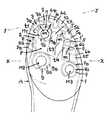
図面は本発明に係る静電気帯電防止靴用の靴底の一実施例を示し、図1は一部の底面図、図2は図1のx−x線拡大断面図、図3は図1のy−y線拡大断面図である。 FIG. 1 shows one embodiment of a shoe sole for an antistatic shoe according to the present invention, FIG. 1 is a partial bottom view, FIG. 2 is an enlarged sectional view taken along line xx of FIG. 1, and FIG. It is a yy line expanded sectional view.
実施例の靴底は、アウトソール部とミッドソール部の2層構造になっており(この2層構造については具体的に図示していない)、ウレタン樹脂を主材とする導電性素材をクッション性と軽量化を図るために発泡成形し、前記のアウトソール部側を微発砲に、ミッドソール部側を高発砲にして好適な履き心地(靴としての)を期待したものである。 The shoe sole of the embodiment has a two-layer structure of an outsole portion and a midsole portion (this two-layer structure is not specifically shown), and cushions a conductive material mainly composed of urethane resin. In order to achieve high performance and light weight, foam molding is performed, and the outsole portion side is finely fired and the midsole portion side is highly fired, so that a suitable comfort (as a shoe) is expected.
図示1は、靴底Aの踏付け部で、該踏付け部1の表面(接地面)には、接地ブロック2,3,4,5,6(以下、接地ブロック2等という)と第二接地ブロック7,8,9(以下、第二接地ブロック7等という)を突設し、該接地ブロック2等と第二接地ブロック7等および靴底Aの踵部側の意匠(接地)ブロックの全部又は一部が床面に接触して静電気を逃がし、人体への静電気の帯電を防ぐようにしてある。 1 shows a stepping portion of a shoe sole A. The surface (grounding surface) of the stepping portion 1 includes a
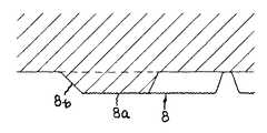
前記接地ブロック2等は、前記踏付け部1(靴底A)の先端側周端部1aすなわち、靴底Aの先端側の周端縁1´と図示2点鎖線で示す親指等の各指t1,t2,t3,t4,t5を載置する部分(位置は、足の大きさすなわち靴底の大きさに対応して特定される)pとの間に突設し、その先端側の自由端側の先端の接地面2a,3a,4a,5a,6a(以下、接地面2a等という)は梨地状にして凹凸状と成し(各接地面2a等の凹凸状は梨地状に限定する必要はない)、該接地面2a等と接地ブロック2等の基端(前期踏みつけ部1の本体)との間の周側面2b,3b,4b,5b,6b(接地ブロック等は、この周側面2b等と前記接地面2a等で構成される)を接地面2a等側から前記基端部にかけて接地面の面外方向に向かって高さが漸小する形態として補強効果を期待している。 The
また、接地ブロック2等の接地面2a等と周側面2b等とが互いに連続する接続部(接地面2a等の端縁部)は曲面状としてある。もっとも、この曲面状は、前記踏付け部1の表面すなわち靴底1の表面の面外方向側(踏付け部1の先端側、側端側)の端縁部が成っていれば、角が床面に引っ掛って躓かないという該「曲面状にする」目的は達成できるのである。 In addition, a connecting portion (an end edge portion of the grounding surface 2a or the like) where the grounding surface 2a or the like of the
実施例の接地ブロック2等は互いに独立して(不連続で)、前記周端部に並設してあるが、連続していても必ずしも不都合はないが、実施例のように互いに独立させていると、各接地ブロック2等間に間隙sがあるため、歩行時に折り曲がりやすく、履き心地の低減を防ぐことができる。このため、実施例の接地ブロック2等は、靴底1の表面の面外方向側に対応する面内方向側に符号mで示す切除部を設け、書く設置ブロック2等が歩行時に折り曲がり易くしてある。 The
前記第二接地ブロック7等は、その内の一の第二接地ブロック7が符号t1で示す前記親指t1の先部で押圧される部分M1に、他の1つの第二接地ブロック8が親指t1の付け根部で押圧される部分M2に、そして、もう一つの第二接地ブロック9が符号t5で示す前記小指t5で押圧される部分M3にそれぞれ配されて、前記接地ブロック2等とほぼ同じ高さ(0.1mm〜5.0mm)で踏付け部1の表面に突設されており、この位置関係によって、バランスよく歩行できるという利点を得られる。 The second grounding block 7 and the like are such that one second grounding block 7 is pressed by a tip M1 of the thumb t1 indicated by reference numeral t1, and the other
第二接地ブロック7等は、接地面7a,8a,9aを接地ブロック2等の接地面2a等と同様に凹凸状(実施例は梨地状)と成し、周側面7b,8b,9bを接地ブロック2等の周側面2b等と同様に、接地面7a,8a,9a側からブロック基端縁にかけて接地面7a,8a,9aの面外方向に向かって高さが漸小する形態としてブロック7,8,9に補強効果が奏するようにしてある。 In the second grounding block 7 and the like, the
実施例の第二接地ブロック7,8,9は平面視欠円リング状としてあるが、これは、指で押圧される前記部分M1,M2,M3にできるだけ狭い面積(広いと滑り易くなる)で押圧力を集中させ、しかも、歩行時に、当該ブロック7,8,9の床面に対する接触がどの部分から始まっても不都合のないようにするためである。 The
第二接地ブロック7等の接地面7a,8a,9aの周端縁が曲面状を成して周側面7b,8b,9bに連続することは、接地ブロック2等と同様である。 Similar to the
因みに、実施品と従来品の静摩擦係数をスリップメーター(トリニティラボ社製)によって静摩擦係数測定したので、その試験結果を下記に示す。 Incidentally, the static friction coefficient of the actual product and the conventional product was measured by a slip meter (manufactured by Trinity Labs), and the test results are shown below.

実施品と従来品とは、静摩擦係数の平均値が0.9の差異があり、0.1ポイントの差を大きいとみる摩擦係数の世界ではこの差は大差であり、はっきりと体感できる差でもあり、本発明は、滑りやすく、その分、躓きにくい製品を提供できることが判る。 There is a difference of 0.9 in the static coefficient of friction between the actual product and the conventional product. In the world of the coefficient of friction, where the difference of 0.1 points is considered large, this difference is a big difference. In addition, it can be seen that the present invention can provide a product that is slippery and is difficult to spread.
1´ 縁部
1a 周端部
2,3,4,5,6 接地ブロック
2a,3a,4a,5a,6a 接地面
2b,3b,4b,5b,6b 周側面1
Claims (3)
Translated fromJapanesePriority Applications (1)
| Application Number | Priority Date | Filing Date | Title |
|---|---|---|---|
| JP2006342567AJP2008149061A (en) | 2006-12-20 | 2006-12-20 | Sole for antistatic shoe |
Applications Claiming Priority (1)
| Application Number | Priority Date | Filing Date | Title |
|---|---|---|---|
| JP2006342567AJP2008149061A (en) | 2006-12-20 | 2006-12-20 | Sole for antistatic shoe |
Publications (1)
| Publication Number | Publication Date |
|---|---|
| JP2008149061Atrue JP2008149061A (en) | 2008-07-03 |
Family
ID=39651907
Family Applications (1)
| Application Number | Title | Priority Date | Filing Date |
|---|---|---|---|
| JP2006342567APendingJP2008149061A (en) | 2006-12-20 | 2006-12-20 | Sole for antistatic shoe |
Country Status (1)
| Country | Link |
|---|---|
| JP (1) | JP2008149061A (en) |
Citations (12)
| Publication number | Priority date | Publication date | Assignee | Title |
|---|---|---|---|---|
| JPS56132906U (en)* | 1980-03-08 | 1981-10-08 | ||
| JPS60114203A (en)* | 1983-11-25 | 1985-06-20 | ウルヴリン ワ−ルド ワイド インコ−ポレイテツド | Shoe sole part for athletic shoes |
| JPS62275401A (en)* | 1986-05-22 | 1987-11-30 | アキレス株式会社 | Conductive vibrationproof shoes |
| JPH0344514U (en)* | 1989-09-01 | 1991-04-25 | ||
| JPH09173105A (en)* | 1995-12-27 | 1997-07-08 | Engel:Kk | Work shoes for high lift work |
| JPH09313207A (en)* | 1996-05-29 | 1997-12-09 | Asahi Corp | Front part structure of shoes |
| JP2001029103A (en)* | 1999-07-15 | 2001-02-06 | Meriito Kk | Antistatic shoe sole structure |
| JP2001275702A (en)* | 2000-03-29 | 2001-10-09 | Mikio Mori | High gripping split-toed heavy-cloth working shoes |
| JP2003230402A (en)* | 2002-02-12 | 2003-08-19 | Achilles Corp | Electroconductive shoe |
| JP2005288159A (en)* | 2004-03-12 | 2005-10-20 | Midori Anzen Co Ltd | Anti-slip sole |
| JP2006020953A (en)* | 2004-07-09 | 2006-01-26 | Bridgestone Sports Co Ltd | Golf shoes, soles and studs therefor |
| JP2006254931A (en)* | 2005-03-15 | 2006-09-28 | Miyata:Kk | Footwear |
- 2006
- 2006-12-20JPJP2006342567Apatent/JP2008149061A/enactivePending
Patent Citations (12)
| Publication number | Priority date | Publication date | Assignee | Title |
|---|---|---|---|---|
| JPS56132906U (en)* | 1980-03-08 | 1981-10-08 | ||
| JPS60114203A (en)* | 1983-11-25 | 1985-06-20 | ウルヴリン ワ−ルド ワイド インコ−ポレイテツド | Shoe sole part for athletic shoes |
| JPS62275401A (en)* | 1986-05-22 | 1987-11-30 | アキレス株式会社 | Conductive vibrationproof shoes |
| JPH0344514U (en)* | 1989-09-01 | 1991-04-25 | ||
| JPH09173105A (en)* | 1995-12-27 | 1997-07-08 | Engel:Kk | Work shoes for high lift work |
| JPH09313207A (en)* | 1996-05-29 | 1997-12-09 | Asahi Corp | Front part structure of shoes |
| JP2001029103A (en)* | 1999-07-15 | 2001-02-06 | Meriito Kk | Antistatic shoe sole structure |
| JP2001275702A (en)* | 2000-03-29 | 2001-10-09 | Mikio Mori | High gripping split-toed heavy-cloth working shoes |
| JP2003230402A (en)* | 2002-02-12 | 2003-08-19 | Achilles Corp | Electroconductive shoe |
| JP2005288159A (en)* | 2004-03-12 | 2005-10-20 | Midori Anzen Co Ltd | Anti-slip sole |
| JP2006020953A (en)* | 2004-07-09 | 2006-01-26 | Bridgestone Sports Co Ltd | Golf shoes, soles and studs therefor |
| JP2006254931A (en)* | 2005-03-15 | 2006-09-28 | Miyata:Kk | Footwear |
Similar Documents
| Publication | Publication Date | Title |
|---|---|---|
| US20160242504A1 (en) | Footwear assembley and associated method | |
| JP2012101057A (en) | Outsole tread pattern | |
| JP2014054536A (en) | Outer sole of footwear | |
| SK500342013A3 (en) | Footwear with non-slip soles | |
| JP5747218B2 (en) | Anti-slip sole and mold for molding the sole | |
| US20110314696A1 (en) | Shoe insert for heeled shoes and method therefor | |
| JP2000106903A (en) | Slip-resistant shoe sole | |
| CN102166054A (en) | Fishing shoe and producing method thereof | |
| JP2008149061A (en) | Sole for antistatic shoe | |
| JP5923224B1 (en) | Shoe sole suitable for walking | |
| KR101634567B1 (en) | Protection pad for stud of shoe | |
| CN210043274U (en) | slippers | |
| JP2009072540A (en) | Backing material of shoe | |
| JP2007275225A (en) | Nonslip shoe outsole | |
| JP5795169B2 (en) | Mounting member | |
| JP2002165607A (en) | Slip resistant sole | |
| JP3153951U (en) | footwear | |
| JP2001098401A (en) | Work socks | |
| CN201048600Y (en) | Shoes with dust removal function | |
| CN205671607U (en) | Sole of shoe | |
| CN202170608U (en) | Pedal anti-slip structure | |
| US20160316854A1 (en) | Footwear device | |
| CN209391171U (en) | Lightweight non-slip soles and light non-slip shoes | |
| JP3167252U (en) | Prosthetic assist device | |
| CN204218031U (en) | A kind of Antiskid sole |
Legal Events
| Date | Code | Title | Description |
|---|---|---|---|
| A621 | Written request for application examination | Free format text:JAPANESE INTERMEDIATE CODE: A621 Effective date:20080829 | |
| A977 | Report on retrieval | Free format text:JAPANESE INTERMEDIATE CODE: A971007 Effective date:20110816 | |
| A131 | Notification of reasons for refusal | Free format text:JAPANESE INTERMEDIATE CODE: A131 Effective date:20110913 | |
| A131 | Notification of reasons for refusal | Free format text:JAPANESE INTERMEDIATE CODE: A131 Effective date:20120110 | |
| A521 | Written amendment | Free format text:JAPANESE INTERMEDIATE CODE: A523 Effective date:20120120 | |
| A02 | Decision of refusal | Free format text:JAPANESE INTERMEDIATE CODE: A02 Effective date:20120424 |