JP2008147319A - Cooling system - Google Patents
Cooling systemDownload PDFInfo
- Publication number
- JP2008147319A JP2008147319AJP2006331271AJP2006331271AJP2008147319AJP 2008147319 AJP2008147319 AJP 2008147319AJP 2006331271 AJP2006331271 AJP 2006331271AJP 2006331271 AJP2006331271 AJP 2006331271AJP 2008147319 AJP2008147319 AJP 2008147319A
- Authority
- JP
- Japan
- Prior art keywords
- heat
- cooling
- radiator
- heat pipe
- board
- Prior art date
- Legal status (The legal status is an assumption and is not a legal conclusion. Google has not performed a legal analysis and makes no representation as to the accuracy of the status listed.)
- Granted
Links
Images


Classifications
- H—ELECTRICITY
- H01—ELECTRIC ELEMENTS
- H01L—SEMICONDUCTOR DEVICES NOT COVERED BY CLASS H10
- H01L2924/00—Indexing scheme for arrangements or methods for connecting or disconnecting semiconductor or solid-state bodies as covered by H01L24/00
- H01L2924/0001—Technical content checked by a classifier
- H01L2924/0002—Not covered by any one of groups H01L24/00, H01L24/00 and H01L2224/00
Landscapes
- Cooling Or The Like Of Semiconductors Or Solid State Devices (AREA)
- Cooling Or The Like Of Electrical Apparatus (AREA)
Abstract
Translated fromJapaneseDescription
Translated fromJapaneseこの発明は、半導体素子の発熱する電子素子を有する電子装置を効果的に冷却するための冷却装置に関する。 The present invention relates to a cooling device for effectively cooling an electronic device having an electronic element that generates heat from a semiconductor element.
電子装置を構成する半導体素子は、年々その容量が増大し、発熱量も多くなっている。そのため、このような電子装置を冷却するための冷却装置も大形にして冷却容量を増大する必要がある。 The capacity of semiconductor elements constituting electronic devices is increasing year by year, and the amount of heat generated is also increasing. Therefore, it is necessary to increase the cooling capacity by increasing the size of the cooling device for cooling such an electronic device.
ところで、このような冷却装置としては、図6に示すように平板状の冷却基板71の一面に櫛歯状に放熱フィン72を多数結合して構成した櫛歯形冷却体70を電子装置などの発熱体80に取り付け、この冷却体70の放熱フィン72を自然冷却または強制冷却することにより発熱体80の冷却を行うようにしたものが、最も一般的である。 By the way, as such a cooling device, as shown in FIG. 6, a comb-
このような櫛歯形冷却体を用いた従来の冷却装置は、冷却容量を大きくするために、冷却基板71および放熱フィン72の形状を変えずにただ単にこれらの寸法を大きくしても、寸法が大きくなるにしたがって冷却基板71および放熱フィン72の放熱効率が低下するため、例えば、冷却体の体積を2倍に増大したとしても、冷却容量を2倍にすることはできず、せいぜい1.5倍程度にしか増加させることができない。このため、櫛歯形冷却体だけを用いた冷却装置は、冷却容量の増大に限界があり、冷却可能な電子装置等の発熱体の容量も限定される。 In the conventional cooling device using such a comb-shaped cooling body, in order to increase the cooling capacity, even if these dimensions are simply increased without changing the shapes of the
特許文献1および2に示されるような放熱フィンとヒートパイプを組み合わせた冷却装置とすれば、より容量の大きい電子装置の冷却が可能となる。このような放熱フィンとヒートパイプを組み合わせた従来の冷却装置を図7に示す。 If the cooling device is a combination of heat radiation fins and heat pipes as shown in
この図7の従来の冷却装置は、クリップ74により電子装置などの発熱体80に結合された冷却基板71にU字形のヒートパイプ73の受熱端部となる中間部を熱的に結合し、このヒートパイプ73の放熱端となる先端部に複数の放熱フィン72を直接結合して構成している。 The conventional cooling device of FIG. 7 thermally couples an intermediate portion serving as a heat receiving end portion of a U-shaped
このような冷却装置によれば、電子装置などの発熱体80の熱は冷却基板71からヒートパイプ73により放熱端側の放熱フィン72に運ばれてこの放熱フィン72から自然冷却または強制冷却によって放熱されることにより、発熱体80の冷却が行われる。このように、ヒートパイプ73を用いると、ヒートパイプの特性により、その受熱端と放熱端の間で低温度差で熱輸送が可能になるため、ヒートパイプの放熱端となる先端部でも十分な冷却性能が得られる。そのため、先端部の放熱フィンを大きくしたり、その枚数を多くしたりすると、それに比例して冷却容量が増大し、大容量の電子装置などの発熱体の冷却が可能となる。 According to such a cooling device, the heat of the
しかして、前記のようなヒートパイプを用いた従来の冷却装置においては、図7(b)に示すように、平板の薄板からなる放熱フィン72の平板面にヒートパイプを挿通するため貫通孔72aを設け、この貫通孔72aにヒートパイプ73の放熱端となる先端部を挿入してろう付けしたり、圧入したりすることにより放熱フィン72とヒートパイプ73との機械的および熱的な結合を行うようにしている。 Therefore, in the conventional cooling device using the heat pipe as described above, as shown in FIG. 7B, the
このため、このような冷却装置おいても、冷却容量が増大すると、大形の放熱フィンを多数ヒートパイプに直接結合する必要があるため、高い加工精度が必要になるとともに、ろう付け等による結合作業の困難度が高まり、ヒートパイプと放熱フィンの結合作業に多大の労力とコストが必要となる問題がある。 For this reason, even in such a cooling device, when the cooling capacity increases, it is necessary to directly connect a large number of large radiating fins to the heat pipe. There is a problem that the degree of difficulty of work increases, and a great deal of labor and cost is required for the work of joining the heat pipe and the radiating fin.
図8に、特許文献3に示された従来の冷却装置を示す。この図8に示す冷却装置は、電子装置などの発熱体80の取り付けられた冷却基板71に受熱端部を結合されたヒートパイプ73の放熱端となる先端部を、冷却体90を構成する放熱フィン92の上に載置し、カバー93により固定するようにしている。そして、冷却ファン95により、放熱フィン92に冷却空気を強制送風して冷却を行う。 FIG. 8 shows a conventional cooling device disclosed in
この図8の従来装置によれば、ヒートパイプ73の放熱端となる先端部が放熱フィンの上面に載置して、固定されているので、前記の図7に示す従来装置のうようにヒートパイプを放熱フィンに貫通して取り付けるものに比して、ヒートパイプと放熱フィンとの結合作業が容易となり、前記の問題は解決できる。 According to the conventional device of FIG. 8, the tip portion which becomes the heat radiating end of the
しかし、この図8の従来装置においては、ヒートパイプが放熱フィンの上に載置されてこれと接触するだけであるので、特にヒートパイプが円形断面の金属管で構成されている場合は、カバー93により固定されているといえども、ヒートパイプと放熱フィンとの接触面積が小さくなるため、ヒートパイプから放熱フィンへの熱伝達効率が低くなり、冷却効果を高めることができないという不都合がある。
この発明は、前記のような従来装置における不都合を解消するため、ヒートパイプから放熱体への熱伝達効率を高くして、冷却効果が高く、かつ大容量化の容易な冷却装置を提供することを課題とするものである。 In order to eliminate the disadvantages of the conventional apparatus as described above, the present invention provides a cooling apparatus that increases the heat transfer efficiency from the heat pipe to the heat radiating body, has a high cooling effect, and can easily increase the capacity. Is an issue.
前記の課題を解決するため、この発明は、電子装置などの発熱体の取り付けられた冷却基板と、放熱基板に複数の放熱フィンを結合して形成した放熱体とを設け、この冷却基板と放熱体とをヒートパイプにより熱的に結合したことを特徴とするものである。 In order to solve the above-described problems, the present invention provides a cooling substrate on which a heating element such as an electronic device is attached, and a radiator that is formed by coupling a plurality of radiation fins to the radiation board. The body is thermally coupled by a heat pipe.
この発明においては、前記放熱体の放熱基板に取付穴を形成し、この取付穴に前記ヒートパイプの放熱端となる側の端部を挿入してヒートパイプを前記放熱体に結合するようにするのがよい。 In the present invention, a mounting hole is formed in the heat radiating board of the heat radiating body, and an end of the heat pipe serving as a heat radiating end is inserted into the mounting hole so that the heat pipe is coupled to the heat radiating body. It is good.
また、この発明おいては、前記ヒートパイプの放熱端となる側の端部に補助放熱体を結合し、この補助放熱体に前記放熱体の放熱基板を結合するようにすることもできる。この場合、前記補助放熱体に少なくとも1つの平坦な接合面を形成し、この接合面に前記放熱体の放熱基板を接合して結合するのがよい。 In the present invention, an auxiliary heat radiating body may be coupled to an end portion of the heat pipe that becomes a heat radiating end, and a heat radiating board of the heat radiating body may be coupled to the auxiliary heat radiating body. In this case, it is preferable that at least one flat joint surface is formed on the auxiliary heat radiator, and a heat radiation substrate of the heat radiator is joined and bonded to the joint surface.
さらに、この発明においては、冷却容量が不足する場合は、電子装置などの発熱体の取り付けられた冷却基板と、放熱基板に複数の放熱フィンを結合して形成した放熱体とを設け、この冷却基板と放熱体とをヒートパイプにより熱的に結合し、さらに放熱基板に複数の放熱フィンを結合して形成した別の放熱体を設け、前記放熱体の放熱基板と前記別の放熱体の放熱基板とをヒートパイプにより熱的に連結するようにすることができる。 Further, in the present invention, when the cooling capacity is insufficient, a cooling substrate on which a heating element such as an electronic device is attached, and a radiator that is formed by coupling a plurality of radiation fins to the radiation board are provided, and this cooling is performed. The substrate and the heat radiating body are thermally coupled by a heat pipe, and another heat radiating body formed by coupling a plurality of heat radiating fins to the heat radiating substrate is provided, and the heat radiating board of the heat radiating body and the heat radiation of the other heat radiating body are provided. The substrate can be thermally connected by a heat pipe.
このようにこの発明によれば、電子装置などの発熱体の取り付けられた冷却基板と、放熱基板に複数の放熱フィンを結合して形成した放熱体とを設け、この冷却基板と放熱体とをヒートパイプにより熱的に結合して冷却装置を構成しているので、ヒートパイプは放熱フィンに直接結合することなく放熱フィンの結合された放熱体の放熱基板に結合することにより、ヒートパイプの全外周を冷却体の放熱基板と接触させて結合するので放熱体との接触面積が大きくなり、ヒートパイプから放熱体への熱伝達効率を高めることができるとともに、その結合精度を高くする必要がないため、ヒートパイプへの放熱フィンの結合作業が容易となり、簡単に冷却容量を高めることができる。 As described above, according to the present invention, a cooling board on which a heating element such as an electronic device is attached, and a radiator that is formed by coupling a plurality of radiation fins to the radiator board are provided. Since the cooling device is configured by thermally coupling with the heat pipe, the heat pipe is not directly coupled to the heat radiating fin, but is coupled to the heat radiating board of the heat radiating body to which the heat radiating fin is coupled. Since the outer periphery contacts with the heat dissipation substrate of the cooling body and is combined, the contact area with the heat dissipation body is increased, the heat transfer efficiency from the heat pipe to the heat dissipation body can be increased, and there is no need to increase the coupling accuracy. For this reason, it is easy to connect the radiating fins to the heat pipe, and the cooling capacity can be easily increased.
この発明の実施の形態を、図に示す実施例に基づいて説明する。 Embodiments of the present invention will be described based on examples shown in the drawings.
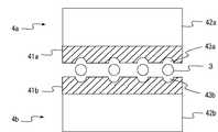
図1はこの発明の第1の実施例を示すもので、(a)はその正面断面図、(b)はその平面図、(c)は(a)におけるc−c線の断面図である。 FIG. 1 shows a first embodiment of the present invention, in which (a) is a front sectional view thereof, (b) is a plan view thereof, and (c) is a sectional view taken along line cc in (a). .
この図1において、1は冷却基板であり、電子装置等の発熱体2が上下両面に結合されている。この基板1の中心部に設けられた結合穴11にヒートパープ3の受熱端となる側の端部を挿入して、冷却基板1にヒートパイプ3を熱的に結合する。 In FIG. 1,
4は、放熱基板41の対向する両面に、ろう付け、またはカシメ加工等により多数の放熱フィン42を結合して構成した放熱体である。この放熱体4の放熱基板41の中心部に取付穴43を設け、この取付穴43にヒートパイプ3の放熱端となる側の端部を挿入して熱的に結合する。
このヒートパイプ3と放熱体4の放熱基板41との結合は、取付穴43に挿入されたヒートパイプと基板41とをろう付けしたり、ヒートパイプの外径を多少基板41の取付穴43の内径より大きくして挿入時に圧入することにより締り嵌めにしたりすることにより熱的に良好な結合となるようにする。冷却基板1とヒートパイプ3の結合も同様である。 The
この実施例によれば、図1(c)から明らかなように、ヒートパイプ3の放熱端側の端部が放熱体4の放熱基板41の取付穴43に挿入されてこの基板41と結合されるため、ヒートパイプ3の全外周が基板41と接触すすため、両者の接触面積が大きくなる。これによりヒートパイプ3から放熱体4への熱伝達効率が高くなるため、発熱体2で発生された熱を冷却基板1からこのヒートパイプ3を介して放熱体4へ良好に伝達でき、放熱フィン42から外気へ効果的に放熱することができ、高い冷却効果を得ることできる。 According to this embodiment, as is apparent from FIG. 1 (c), the end of the
なお、この図1に示す放熱体4は、全体が一体的に構成されているが、図2に示すように、放熱体4の放熱基板41を中心から上下に2分割して構成することもできる。 The entire
この場合は、分割された放熱体4a、4bの放熱基板41a、41bの対向面にヒートパイプ3を挿入するための断面が半円の取付溝43a、43bを形成し、一方の冷却体4bの取付溝43bにヒートパイプ3を納め、その上から他方の放熱体4aを重ね合わせて、接合部分をろう付けなどにより結合して、放熱体4a、4bおよびヒートパイプ3を一体的に結合する。 In this case, mounting
このように構成すると、放熱体4を分割して製造することができるので、これ自身の製造が容易となるとともに、ヒートパイプの放熱体への挿入作業が容易となる。 If comprised in this way, since the
図3および図4にこの発明の第2の実施例を示す。図3は組立て前の分解状態を示すもので、(a)はその正面断面図、(b)は(a)におけるb−b線の断面図である。図4は組立ての完成した状態の正面断面図を示すものである。 3 and 4 show a second embodiment of the present invention. 3A and 3B show the disassembled state before assembly, where FIG. 3A is a front sectional view thereof, and FIG. 3B is a sectional view taken along line bb in FIG. FIG. 4 shows a front sectional view of the assembled state.
図3および図4に示すようにこの実施例においては、電子装置等の発熱体2の結合された冷却基板1に受熱端側を結合されたヒートパイプ3の放熱端となる側の端部に補助放熱体4cを結合する。4aおよび4bは、補助放熱体4cとは、別に構成された放熱体であり、それぞれ平板状の放熱基板41aおよび41bに多数の放熱フィン42aおよび42bを結合して構成されている。 As shown in FIGS. 3 and 4, in this embodiment, the heat receiving end side is coupled to the
補助放熱体4cは、放熱体42a,42bとの結合を容易にするため、この実施例においては対向する2面に平坦な接合面46c、47cが形成さた直方体状とし、その中心部にこの接合面と平行に設けられたヒートパイプ取付け用の取付穴43cを備えている。 In order to facilitate the coupling with the
この取付穴43cに、図3(a)に示すように冷却基板1に受熱端側の端部を結合されたヒートパイプ3の放熱端となる側の端部を挿入し、ろう付けやカシメ加工等によりヒートパイプ3と補助放熱体4cとを熱的に良好に結合する。 As shown in FIG. 3 (a), the mounting
このヒートパイプ3に結合された補助放熱体4cの対向した上下の平坦な接合面46c、47cにそれぞれ放熱体4aおよび4bの平板状の放熱基板41aおよび41bの平板面を接合して、ろう付けなどにより熱的および機械的に結合する。このようにして補助放熱体4cに放熱体4a、4bを結合し、組立てを完成した冷却装置は、図4に示すとおりとなる。 The flat plate surfaces of the flat plate-like
この第2の実施例においては、ヒートパイプ3は、放熱体4a、4bに結合される補助放熱体4cに全外周を接して結合されるので、ヒートパイプ3から補助放熱体4cへの熱伝達効率が高くなり、そして補助放熱体4cと放熱体4a、4bとも平坦な広い面積の接合面で接合して結合されるので、補助放熱体4cから放熱体4a、4bへの熱伝達も良好に行われる。このため、発熱体2で発生した熱は、冷却基板1からヒートパイプ3により放熱体4a、4bへ効率よく伝達されて、放熱フィン42a、42bから放熱される。 In this second embodiment, the
この第2の実施例においても、ヒートパイプ3をブロック状の補助放熱体に結合し、この補助放熱体を放熱基板に放熱フィンの取り付けて構成した放熱体に結合することによりヒートパイプと放熱フィンとを結合するので、放熱フィンを直接ヒートパイプに結合するようにした従来装置と比較すると、ヒートパイプと放熱フィンの結合作業がはるかに容易となる。 Also in the second embodiment, the
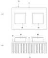
図5は、この発明の第3の実施例を示すものである。この図5において、1、2および3は、それぞれ、前記した実施例と同様に構成された、冷却基板、電子装置等の発熱体およびヒートパイプである。4は、放熱基板41とこれに取付けられた多数の放熱フィン42とからなる第1の放熱体であり、受熱端となる側の端部を冷却基板1に結合されたヒートパイプ3の放熱端となる側の端部に結合される。この第1の放熱体4だけでは冷却容量が不足するために、この実施例においては、さらにもう1個、この第1の放熱体4と同じく放熱基板41dと多数の放熱フィン42dとから構成された第2の放熱体4dを設けている。そして、この第2の放熱体4dの放熱基板41dと第1の放熱体4の放熱基板41とを前記のヒートパイプ3とは別のヒートパイプ3dにより熱的に結合する。 FIG. 5 shows a third embodiment of the present invention. In FIG. 5,
これにより、発熱体2の熱が、2個の放熱体4および4dから放熱されるようになり、冷却容量が放熱体1個の場合の2倍にすることができるので、より容量の大きな発熱体2の冷却を行うことができる。 As a result, the heat of the
なお、ここでは、2個の放熱体を結合するヒートパイプを発熱体の取り付けられた冷却基板1に結合したヒートパイプ3とは別のヒートパイプとしているが、前記のヒートパイプ3を放熱体4を貫通して延長し、その先端部に追加する放熱体4dを結合するようにしてもよいのである。これによっても、放熱体の容積が増大し、冷却容量を増加することができる。 Here, the heat pipe that couples the two heat radiators is a heat pipe different from the
この発明によれば、電子装置などの発熱体の結合された冷却基板から熱を伝達するヒートパイプを予め放熱基板に放熱フィンを取り付けて構成した放熱体に熱的に結合することにより、ヒートパイプと放熱フィンとの結合が容易となるだけでなく、放熱基板に放熱フィンを取り付けて構成した放熱体として市販されている量産型の櫛歯形冷却体(ヒートシンク)を使用することが可能となるため、冷却装置のコストを低減できる効果もえられる。 According to the present invention, a heat pipe that transfers heat from a cooling substrate to which a heating element such as an electronic device is coupled is thermally coupled to a heat radiator that is configured by attaching a radiation fin to the heat radiation board in advance, thereby In addition to facilitating the coupling between the heat sink and the heat radiation fin, it is possible to use a mass-produced comb-shaped cooling body (heat sink) that is commercially available as a heat radiator constructed by attaching the heat radiation fin to the heat radiation board. Moreover, the effect which can reduce the cost of a cooling device is also acquired.
1:冷却基板
2:発熱体(電子装置)
3:ヒートパイプ
4:放熱体
41:放熱基板
42:放熱フィン1: Cooling substrate 2: Heating element (electronic device)
3: Heat pipe 4: Heat radiating body 41: Heat radiating substrate 42: Heat radiating fin
Claims (5)
Translated fromJapanesePriority Applications (1)
| Application Number | Priority Date | Filing Date | Title |
|---|---|---|---|
| JP2006331271AJP5076476B2 (en) | 2006-12-08 | 2006-12-08 | Cooling system |
Applications Claiming Priority (1)
| Application Number | Priority Date | Filing Date | Title |
|---|---|---|---|
| JP2006331271AJP5076476B2 (en) | 2006-12-08 | 2006-12-08 | Cooling system |
Publications (2)
| Publication Number | Publication Date |
|---|---|
| JP2008147319Atrue JP2008147319A (en) | 2008-06-26 |
| JP5076476B2 JP5076476B2 (en) | 2012-11-21 |
Family
ID=39607182
Family Applications (1)
| Application Number | Title | Priority Date | Filing Date |
|---|---|---|---|
| JP2006331271AExpired - Fee RelatedJP5076476B2 (en) | 2006-12-08 | 2006-12-08 | Cooling system |
Country Status (1)
| Country | Link |
|---|---|
| JP (1) | JP5076476B2 (en) |
Cited By (3)
| Publication number | Priority date | Publication date | Assignee | Title |
|---|---|---|---|---|
| JP2012013277A (en)* | 2010-06-30 | 2012-01-19 | Toshiba Home Technology Corp | Heat sink |
| JP2012229909A (en)* | 2011-04-25 | 2012-11-22 | Google Inc | Thermosyphon system for electronic device |
| CN107742614A (en)* | 2017-10-30 | 2018-02-27 | 镇江佳鑫精工设备有限公司 | A kind of semiconductor equipment circuit board |
Citations (4)
| Publication number | Priority date | Publication date | Assignee | Title |
|---|---|---|---|---|
| JPH0346355A (en)* | 1989-07-14 | 1991-02-27 | Furukawa Electric Co Ltd:The | Heat-transportation device of heat-pipe system |
| JPH0629683A (en)* | 1992-03-31 | 1994-02-04 | Furukawa Electric Co Ltd:The | Heat pipe type heat dissipation unit for electronic devices |
| JPH08148870A (en)* | 1994-11-16 | 1996-06-07 | Hitachi Ltd | Heat dissipation structure for electronic devices |
| JP2000340724A (en)* | 1999-05-26 | 2000-12-08 | Fujikura Ltd | Heat sink fixing structure |
- 2006
- 2006-12-08JPJP2006331271Apatent/JP5076476B2/ennot_activeExpired - Fee Related
Patent Citations (4)
| Publication number | Priority date | Publication date | Assignee | Title |
|---|---|---|---|---|
| JPH0346355A (en)* | 1989-07-14 | 1991-02-27 | Furukawa Electric Co Ltd:The | Heat-transportation device of heat-pipe system |
| JPH0629683A (en)* | 1992-03-31 | 1994-02-04 | Furukawa Electric Co Ltd:The | Heat pipe type heat dissipation unit for electronic devices |
| JPH08148870A (en)* | 1994-11-16 | 1996-06-07 | Hitachi Ltd | Heat dissipation structure for electronic devices |
| JP2000340724A (en)* | 1999-05-26 | 2000-12-08 | Fujikura Ltd | Heat sink fixing structure |
Cited By (5)
| Publication number | Priority date | Publication date | Assignee | Title |
|---|---|---|---|---|
| JP2012013277A (en)* | 2010-06-30 | 2012-01-19 | Toshiba Home Technology Corp | Heat sink |
| JP2012229909A (en)* | 2011-04-25 | 2012-11-22 | Google Inc | Thermosyphon system for electronic device |
| US9521786B2 (en) | 2011-04-25 | 2016-12-13 | Google Inc. | Thermosiphon systems for electronic devices |
| US10225959B2 (en) | 2011-04-25 | 2019-03-05 | Google Llc | Thermosiphon systems for electronic devices |
| CN107742614A (en)* | 2017-10-30 | 2018-02-27 | 镇江佳鑫精工设备有限公司 | A kind of semiconductor equipment circuit board |
Also Published As
| Publication number | Publication date |
|---|---|
| JP5076476B2 (en) | 2012-11-21 |
Similar Documents
| Publication | Publication Date | Title |
|---|---|---|
| CN100470773C (en) | heat pipe radiator | |
| WO2011087117A1 (en) | Heat sink | |
| WO2011105364A1 (en) | Heat sink | |
| CN100456461C (en) | Heat sink of heat pipe | |
| WO2018021009A1 (en) | Cooling apparatus | |
| JP2001223308A (en) | Heat sink | |
| JP5667739B2 (en) | Heat sink assembly, semiconductor module, and semiconductor device with cooling device | |
| JP5076476B2 (en) | Cooling system | |
| CN101316495B (en) | Heat sink assembly | |
| JP6203165B2 (en) | Array module | |
| JP7113914B2 (en) | Heatsinks, heatsink assemblies, electronics, and methods of making heatsinks | |
| JP2001251079A (en) | Heat sink using heat pipe and method of manufacturing heat pipe | |
| JP2014115054A (en) | Self-excited vibration type heat pipe | |
| JP2011169506A (en) | Connecting section of heat pipe heat receiving section and method of connecting heat pipe heat receiving section | |
| JPH10107192A (en) | heatsink | |
| JP5226463B2 (en) | Heat sink with louver and method of assembling the same | |
| JP2007248037A (en) | High-efficiency heat radiation device | |
| JP3959428B2 (en) | Stereo heat pipe radiator | |
| JP2004071635A (en) | Tower heat sink | |
| JPH10185466A (en) | Heat pipe radiator | |
| JP2018031549A (en) | Heat radiator | |
| JP3843873B2 (en) | Heat sink and heat sink manufacturing method | |
| JP7235922B1 (en) | heat sink | |
| TWI843632B (en) | Radiator | |
| TWI305132B (en) |
Legal Events
| Date | Code | Title | Description |
|---|---|---|---|
| A621 | Written request for application examination | Free format text:JAPANESE INTERMEDIATE CODE: A621 Effective date:20090515 | |
| A977 | Report on retrieval | Free format text:JAPANESE INTERMEDIATE CODE: A971007 Effective date:20091126 | |
| A711 | Notification of change in applicant | Free format text:JAPANESE INTERMEDIATE CODE: A712 Effective date:20110422 | |
| A131 | Notification of reasons for refusal | Free format text:JAPANESE INTERMEDIATE CODE: A131 Effective date:20120124 | |
| A521 | Written amendment | Free format text:JAPANESE INTERMEDIATE CODE: A523 Effective date:20120312 | |
| A131 | Notification of reasons for refusal | Free format text:JAPANESE INTERMEDIATE CODE: A131 Effective date:20120522 | |
| A521 | Written amendment | Free format text:JAPANESE INTERMEDIATE CODE: A523 Effective date:20120709 | |
| TRDD | Decision of grant or rejection written | ||
| A01 | Written decision to grant a patent or to grant a registration (utility model) | Free format text:JAPANESE INTERMEDIATE CODE: A01 Effective date:20120731 | |
| A01 | Written decision to grant a patent or to grant a registration (utility model) | Free format text:JAPANESE INTERMEDIATE CODE: A01 | |
| A61 | First payment of annual fees (during grant procedure) | Free format text:JAPANESE INTERMEDIATE CODE: A61 Effective date:20120813 | |
| FPAY | Renewal fee payment (prs date is renewal date of database) | Free format text:PAYMENT UNTIL: 20150907 Year of fee payment:3 | |
| R150 | Certificate of patent (=grant) or registration of utility model | Free format text:JAPANESE INTERMEDIATE CODE: R150 | |
| LAPS | Cancellation because of no payment of annual fees |