JP2008145162A - 3D shape measuring device - Google Patents
3D shape measuring deviceDownload PDFInfo
- Publication number
- JP2008145162A JP2008145162AJP2006330309AJP2006330309AJP2008145162AJP 2008145162 AJP2008145162 AJP 2008145162AJP 2006330309 AJP2006330309 AJP 2006330309AJP 2006330309 AJP2006330309 AJP 2006330309AJP 2008145162 AJP2008145162 AJP 2008145162A
- Authority
- JP
- Japan
- Prior art keywords
- optical system
- shape measuring
- dimensional shape
- measuring apparatus
- imaging
- Prior art date
- Legal status (The legal status is an assumption and is not a legal conclusion. Google has not performed a legal analysis and makes no representation as to the accuracy of the status listed.)
- Pending
Links
Images


Landscapes
- Length Measuring Devices By Optical Means (AREA)
Abstract
Translated fromJapaneseDescription
Translated fromJapanese本発明はスリット投影法(光切断法)を用いた三次元形状測定装置に関するものである。 The present invention relates to a three-dimensional shape measuring apparatus using a slit projection method (light cutting method).
近年、非接触で物体の三次元形状を測定する必要性が高まっている。物体の三次元形状を非接触で測定する方法には大別して二種類の方法がある。一つは受動的な方法であって物体を複数台のカメラで撮影する立体写真法が代表的なものである。これらの方法は、汎用的で物体の形状や大きさ等の制限が少ないという利点がある。他の一つは能動的な方法であって光レーダー法、アクティブステレオ法、モアレトポグラフィ法、照度差ステレオ法、干渉法などであり、一般に受動的な方法より精度が高いという利点がある。 In recent years, there has been an increasing need to measure the three-dimensional shape of an object without contact. There are two types of methods for measuring the three-dimensional shape of an object in a non-contact manner. One is a passive method, and a stereoscopic photography method in which an object is photographed by a plurality of cameras is representative. These methods are advantageous in that they are versatile and have few restrictions on the shape and size of the object. The other one is an active method, such as an optical radar method, an active stereo method, a moire topography method, an illuminance difference stereo method, an interference method, and the like, and generally has an advantage of higher accuracy than a passive method.
高精度測定にはアクティブステレオ法が多用され、そこでは代表的な方法としてスリット投影法(光切断法)がある。これは、被測定物体にスリットパターンを投影し、被測定物表面に映るスリットパターンの位置をカメラ画像上で検出し、三角測量の原理を用いて物体の二次元情報を得る。そして、スリットパターンを走査することにより、物体全体の三次元形状を得ることができる。この方法では空間分解能は走査分解能に依存するので、高い精度(分解能)を得るためには走査分解能を高めなければならない。これを改善する方法として、マルチスリットパターンを投影し、分割されたスリット毎に三角測量を行うものがある。これによれば、ピッチの異なる種々の投影パターンを投影することにより、測定の信頼性を高めることができる。 The active stereo method is frequently used for high-accuracy measurement, and there is a slit projection method (light cutting method) as a representative method. In this method, a slit pattern is projected onto the object to be measured, the position of the slit pattern reflected on the surface of the object to be measured is detected on the camera image, and two-dimensional information of the object is obtained using the principle of triangulation. A three-dimensional shape of the entire object can be obtained by scanning the slit pattern. In this method, since the spatial resolution depends on the scanning resolution, the scanning resolution must be increased in order to obtain high accuracy (resolution). As a method for improving this, there is a method of projecting a multi-slit pattern and performing triangulation for each divided slit. According to this, the reliability of measurement can be improved by projecting various projection patterns having different pitches.
スリット投影法で更に高い空間分解能を達成するためには、受光素子の画素数を増やす、パターンピッチを細かくする、光学系の解像力を高める(開口数を大きくする)などの対策が必要になる。ところが光学系の開口数を大きくして細かいパターンピッチを投影しようとすると、必然的に焦点深度が浅くなり、計測範囲を狭めてしまうという問題があった。 In order to achieve higher spatial resolution by the slit projection method, measures such as increasing the number of pixels of the light receiving element, reducing the pattern pitch, and increasing the resolving power of the optical system (increasing the numerical aperture) are required. However, when trying to project a fine pattern pitch by increasing the numerical aperture of the optical system, there is a problem that the depth of focus inevitably becomes shallow and the measurement range is narrowed.
本発明はこのような事情に鑑みてなされたもので、高い測定精度と広い計測範囲を両立させることができる三次元形状測定装置を提供することを課題とする。 This invention is made | formed in view of such a situation, and makes it a subject to provide the three-dimensional shape measuring apparatus which can make high measurement accuracy and a wide measurement range compatible.
前記課題を解決するための第1の手段は、被検物体にスリットパターンを投影する照明光学系と、前記照明光学系の光軸とは異なる光軸を有し、前記被検物体上のスリットパターンを撮像素子により撮像する撮像光学系と、前記被検物体と、前記照明光学系及び前記撮像光学系とを相対的に移動させる機構と、前記移動機構により相対移動させながら撮像した前記スリットパターンの画像情報に基づいて前記被検物体の三次元データを測定する三次元形状測定装置であって、前記撮像光学系の光軸は、途中で分岐した複数の光軸であり、前記照明光学系の光軸上の互いに異なる点と共役な前記各光軸上の位置に、それぞれ前記撮像素子の中心を配置したことを特徴とする三次元形状測定装置である。 A first means for solving the problem includes an illumination optical system that projects a slit pattern on a test object, and a slit on the test object that has an optical axis different from the optical axis of the illumination optical system. An imaging optical system that images a pattern with an imaging device, a mechanism that relatively moves the object to be examined, the illumination optical system, and the imaging optical system, and the slit pattern that is imaged while being relatively moved by the moving mechanism A three-dimensional shape measuring apparatus for measuring three-dimensional data of the object to be inspected based on image information of the imaging optical system, wherein the optical axis of the imaging optical system is a plurality of optical axes branched in the middle, and the illumination optical system The three-dimensional shape measuring apparatus is characterized in that the center of the imaging device is arranged at a position on each optical axis conjugate with different points on the optical axis.
前記課題を解決するための第2の手段は、前記第1の手段であって、前記複数の光軸に分岐する手段は、ダイクロイックプリズム又はダイクロイックミラーであることを特徴とするものである。 The second means for solving the problem is the first means, and the means for branching to the plurality of optical axes is a dichroic prism or a dichroic mirror.
前記課題を解決するための第3の手段は、前記第1の手段であって、前記複数の光軸に分岐する手段は、偏光ビームスプリッタであることを特徴とするものである。 A third means for solving the problem is the first means, and the means for branching to the plurality of optical axes is a polarization beam splitter.
前記課題を解決するための第4の手段は、前記第1の手段から第3の手段のいずれかであって、前記撮像光学系はアフォーカル系であることを特徴とするものである。 A fourth means for solving the problem is any one of the first to third means, and the imaging optical system is an afocal system.
前記課題を解決するための第5の手段は、前記第1の手段から第4の手段のうちいずれかの光学系複数組を、それらのスリットが互いに平行になるように、前記スリットの長さ方向に並べて配置したことを特徴とする三次元形状測定装置である。 According to a fifth means for solving the above-mentioned problem, the length of the slits is set so that the plurality of optical systems of any one of the first to fourth means are parallel to each other. It is a three-dimensional shape measuring apparatus characterized by being arranged in a direction.
本発明によれば、高い測定精度と広い計測範囲を両立させることができる三次元形状測定装置を提供することができる。 According to the present invention, it is possible to provide a three-dimensional shape measuring apparatus that can achieve both high measurement accuracy and a wide measurement range.
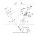
以下、本発明の実施の形態の例を、図を用いて説明する。図1は本発明の実施の形態の1例である三次元形状測定装置の光学系の概要を示す図である。投影光学系21においては、必要に応じてコレクタレンズ(球面鏡を含む)を加えることもできる光源1により、一次元スリットパターン2を照明し、レンズ3、5を用いて基準平面12上に斜め方向からスリットパターンを投影する。スリットの長手方向は図1の紙面に垂直である。開口絞り4が照明系のNAを決定している。 Hereinafter, an example of an embodiment of the present invention will be described with reference to the drawings. FIG. 1 is a diagram showing an outline of an optical system of a three-dimensional shape measuring apparatus which is an example of an embodiment of the present invention. In the projection
レンズ3、5はアフォーカル系を構成している。従って本実施の形態では照明光学系21はテレセントリックとなっている。被測定物体11は、基準平面12を上面とするステージ13上にあって矢印で示すように水平方向に移動させることができる。以上の構成は、従来の光切断法による計測法と同一である。 The
撮像光学系22においては、被測定物体11に投影されたスリットパターンからの光束が、アフォーカル系を構成するレンズ6、8により導かれ、ダイクロイックプリズム9により、波長の異なる光束からなる3つの光路に分離される。分離された光束は、それぞれ撮像素子10a、10b、10cに導かれて、スリットパターンの像を撮像面に結像する。撮像素子10a、10b、10cの撮像面の中心点a、b、cは、それぞれ、投影光学系21から投影される光束上の点A、B、Cと共役な位置に設けられている。なお、開口絞り7が、撮像光学系のNAを決定している。 In the imaging
この実施の形態においては、被測定物体11の表面の高さに応じてA点付近の計測は撮像素子10aで、B、C各点付近の計測はそれぞれ撮像素子10b、10cで行うことにより計測精度を高めることができる。レンズ6、8がアフォーカル系を構成しているため、A、B、C各点付近の計測を同じ精度で行うことができる。 In this embodiment, the measurement near the point A is performed by the
なお、この実施の形態においては、光路分岐手段としてダイクロイックプリズムを使用しているが、ダイクロイックミラーを使用することもでる。又、光路を2分割するのであれば、偏光ビームスプリッタを使用することもできる。 In this embodiment, a dichroic prism is used as the optical path branching means, but a dichroic mirror can also be used. Further, if the optical path is divided into two, a polarizing beam splitter can be used.
以下、本実施の形態における測定可能範囲を、図2を用いて説明する。以下の説明において、撮像素子10a、10b、10cに入射する光の波長を、それぞれλa、λb、λcとする。長方形31Cの短辺方向は撮像素子10cが使用される場合の撮像光学系の焦点深度を示しており、長辺方向は撮像光学系の視野に相当する。つまり図1の撮像素子10Cは、図2の長方形31Cで示される範囲にある物体表面の情報を常に合焦状態で得ることができる。 Hereinafter, the measurable range in the present embodiment will be described with reference to FIG. In the following description, the wavelengths of light incident on the
同様に他の長方形31A、31B内にある物体表面情報も、撮像素子10a、10bによって合焦状態で得ることができる。各長方形の頂点同士が少し重なりあうことが望ましい。ここで被測定物体11を水平方向に移動させることにより、図2における矢印dの範囲の高さの物体を計測することができる。撮像系の物体側NAをNA2とすると、長方形31Cの短辺の長さである焦点深度幅はλc/NA22であるから、長方形31Cの長辺の長さをS、対角線の長さをlとすると、
S=λc tan(θ1+θ2)/NA22 ‥‥(1)
l=λc/(NA22 cos(θ1+θ2)) ‥‥(2)
となる。Similarly, the object surface information in the
S = λc tan (θ1 + θ2) / NA22 (1)
l = λc / (NA22 cos (θ1 + θ2)) (2)
It becomes.
同様に長方形31A、31Bの短辺、長辺、対角線の長さを求めることができる。照明系の中心波長λcの焦点深度は長方形31Cの対角線の長さ以上あればよいから、照明系のNAをNA1とすると、(2)式を用いて、次の不等式が成り立つ。
λc/NA12 > λc/(NA22 cos(θ1+θ2)) ‥‥(3)
λc / NA12 > λc / (NA22 cos (θ1 + θ2)) (3)
このとき、照明系には色収差が必要となり、λa,λb,λcの波長の光束はそれぞれA、B、C点にスリットパターンが結像するようなものであればよい。色収差をつけない場合は各長方形31A、31B、31Cの対角線の和を焦点深度以内とすればよいので、平均波長をλとし、(3)式を用いると
λ/NA12 > Nλ/(NA22 cos(θ1+θ2))) (ただしN=3)
となる。At this time, the illumination system needs to have chromatic aberration, and the light fluxes having the wavelengths of λa, λb, and λc may be such that a slit pattern is formed at points A, B, and C, respectively. Each
It becomes.
A、B、C各点からレンズ6までの距離が異なるため、各点におけるNA2は厳密には等しくはないが、(1)〜(4)式では簡単のためC点でのNAをNA2としている。現実には次の不等式が成り立つ。
NA2A>NA2C>NA2B …(5)Since the distances from the points A, B, and C to the lens 6 are different, the NA2 at each point is not exactly the same. However, in the equations (1) to (4), the NA at the point C is NA for simplicity.2 . In reality, the following inequality holds.
NA2A > NA2C > NA2B (5)
従って解像力をできるだけ揃えるためには、以下の関係が望ましい。
λa>λc>λb …(6)Therefore, the following relationship is desirable to make the resolution as uniform as possible.
λa>λc> λb (6)
図3は、より大きな物体を測定するために、光学ユニットを複数個並べた状態を示す図である。図3(a)において、物体の移動方向は図3の矢印の向きである。投影光学系21a、21bが図1の投影光学系21に相当し、撮像光学系22a、22bが図1の撮像光学系22に対応する。又、点Cにおける投影スリットパターン像がそれぞれの光学系の23a、23bに対応する。その際、図3(b)に示すように、スリットパターン像23aと23bのスリット長さ方向をオーバラップさせる必要がある。そのために、投影光学系21a、21b、撮像光学系22a、22bを千鳥配置している。 FIG. 3 is a diagram showing a state in which a plurality of optical units are arranged in order to measure a larger object. In FIG. 3A, the moving direction of the object is the direction of the arrow in FIG. The projection
1:光源、2:一次元スリットパターン、3:レンズ、4:開口絞り、5:レンズ、6:レンズ、7:開口絞り、8:レンズ、9:ダイクロイックプリズム、10a,10b,10c:撮像素子、11:被測定物体、12:基準平面、13:ステージ、21,21a,21b:照明光学系、22,22a,22b:撮像光学系、23a、23b:スリットパターン像1: Light source, 2: One-dimensional slit pattern, 3: Lens, 4: Aperture stop, 5: Lens, 6: Lens, 7: Aperture stop, 8: Lens, 9: Dichroic prism, 10a, 10b, 10c: Image sensor 11: object to be measured, 12: reference plane, 13: stage, 21, 21a, 21b: illumination optical system, 22, 22a, 22b: imaging optical system, 23a, 23b: slit pattern image
Claims (5)
Translated fromJapanesePriority Applications (1)
| Application Number | Priority Date | Filing Date | Title |
|---|---|---|---|
| JP2006330309AJP2008145162A (en) | 2006-12-07 | 2006-12-07 | 3D shape measuring device |
Applications Claiming Priority (1)
| Application Number | Priority Date | Filing Date | Title |
|---|---|---|---|
| JP2006330309AJP2008145162A (en) | 2006-12-07 | 2006-12-07 | 3D shape measuring device |
Publications (1)
| Publication Number | Publication Date |
|---|---|
| JP2008145162Atrue JP2008145162A (en) | 2008-06-26 |
Family
ID=39605520
Family Applications (1)
| Application Number | Title | Priority Date | Filing Date |
|---|---|---|---|
| JP2006330309APendingJP2008145162A (en) | 2006-12-07 | 2006-12-07 | 3D shape measuring device |
Country Status (1)
| Country | Link |
|---|---|
| JP (1) | JP2008145162A (en) |
Cited By (1)
| Publication number | Priority date | Publication date | Assignee | Title |
|---|---|---|---|---|
| JP2011215089A (en)* | 2010-04-02 | 2011-10-27 | Pulstec Industrial Co Ltd | Three-dimensional shape measuring apparatus |
- 2006
- 2006-12-07JPJP2006330309Apatent/JP2008145162A/enactivePending
Cited By (1)
| Publication number | Priority date | Publication date | Assignee | Title |
|---|---|---|---|---|
| JP2011215089A (en)* | 2010-04-02 | 2011-10-27 | Pulstec Industrial Co Ltd | Three-dimensional shape measuring apparatus |
Similar Documents
| Publication | Publication Date | Title |
|---|---|---|
| KR101639227B1 (en) | Three dimensional shape measurment apparatus | |
| KR100951221B1 (en) | Measurement method of optical axis eccentricity of front and back surface in lens | |
| JP5798810B2 (en) | Image correlation displacement sensor | |
| CN104067158B (en) | Cofocal scanner and use its optical measuring device | |
| JP2005504305A (en) | 3D scanning camera | |
| TW201732263A (en) | Method and system for optical three-dimensional configuration measurement | |
| TWI500901B (en) | Measuring apparatus | |
| JP2009162539A (en) | Lightwave interference measuring device | |
| KR100785802B1 (en) | Three-dimensional shape measuring device | |
| KR101116295B1 (en) | Apparatus for measurment of three-dimensional shape | |
| JP2015108582A (en) | Three-dimensional measurement method and device | |
| JP2016148569A (en) | Image measuring method and image measuring apparatus | |
| US10739125B2 (en) | Precision measurement system using interferometer and image | |
| KR101826127B1 (en) | optical apparatus for inspecting pattern image of semiconductor wafer | |
| JP2025121323A (en) | Measurement device, measurement method, and optical system manufacturing method | |
| JP3595117B2 (en) | Array element inspection method and array element inspection apparatus | |
| CN103471508A (en) | Shear displacement speckle measurement method and device | |
| JP2008145162A (en) | 3D shape measuring device | |
| JP2008145121A (en) | 3D shape measuring device | |
| JP2010101672A (en) | Method and device for inspecting shape in inspection body | |
| JPH07311117A (en) | Multi-lens position measuring device | |
| JP4930834B2 (en) | Shape measurement method | |
| JP2673196B2 (en) | 3D shape sensor | |
| JP2008145268A (en) | Focal plane tilt type confocal surface shape measuring device | |
| JP5965721B2 (en) | Multifocal imaging device |