JP2008143015A - Liquid ejection device - Google Patents
Liquid ejection deviceDownload PDFInfo
- Publication number
- JP2008143015A JP2008143015AJP2006332450AJP2006332450AJP2008143015AJP 2008143015 AJP2008143015 AJP 2008143015AJP 2006332450 AJP2006332450 AJP 2006332450AJP 2006332450 AJP2006332450 AJP 2006332450AJP 2008143015 AJP2008143015 AJP 2008143015A
- Authority
- JP
- Japan
- Prior art keywords
- nozzle row
- row
- liquid
- nozzle
- short
- Prior art date
- Legal status (The legal status is an assumption and is not a legal conclusion. Google has not performed a legal analysis and makes no representation as to the accuracy of the status listed.)
- Pending
Links
- 239000007788liquidSubstances0.000titleclaimsabstractdescription156
- 238000010030laminatingMethods0.000claimsdescription5
- 238000007599dischargingMethods0.000claimsdescription2
- 230000000149penetrating effectEffects0.000claimsdescription2
- 239000000976inkSubstances0.000description34
- 125000006850spacer groupChemical group0.000description9
- 238000003491arrayMethods0.000description4
- 238000004519manufacturing processMethods0.000description3
- 238000000034methodMethods0.000description3
- 230000000694effectsEffects0.000description2
- 239000000049pigmentSubstances0.000description2
- 238000005452bendingMethods0.000description1
- 238000009835boilingMethods0.000description1
- 230000005611electricityEffects0.000description1
- 239000004973liquid crystal related substanceSubstances0.000description1
- 239000011159matrix materialSubstances0.000description1
- 230000003068static effectEffects0.000description1
Images


Landscapes
- Liquid Crystal (AREA)
- Coating Apparatus (AREA)
- Manufacturing Of Printed Wiring (AREA)
- Particle Formation And Scattering Control In Inkjet Printers (AREA)
Abstract
Translated fromJapaneseDescription
Translated fromJapanese本発明は、液体を複数のノズルから吐出する液体吐出装置、例えば、吐出した液滴をドットマトリクス状に配置して文字や図形等を形成する液体吐出装置に関する技術である。 The present invention relates to a liquid ejecting apparatus that ejects liquid from a plurality of nozzles, for example, a liquid ejecting apparatus that forms characters, figures, and the like by arranging ejected droplets in a dot matrix.
従来、液体吐出装置は、吐出する液体の種類毎に複数のノズル列を備える。外部の液体供給源から供給された液体は、供給口から液体流路を経て、各ノズルに対応する圧力室に分配され、各圧力室内で吐出圧力が付与されることで、ノズルから対象物表面に液滴として吐出される。例えば特許文献1のように、インクジェット式プリンタの記録ヘッドは、ブラック、イエロー、シアン、マゼンタ等の各色のインク毎にノズル列、圧力室列、供給口及び液体流路を備えている。これらのノズル列は同一の長さで並列に配置され、各インク供給口は、平面視において、ノズル列の延長方向に配置されている。 Conventionally, a liquid ejection apparatus includes a plurality of nozzle rows for each type of liquid to be ejected. The liquid supplied from the external liquid supply source is distributed from the supply port to the pressure chamber corresponding to each nozzle through the liquid flow path, and the discharge pressure is applied in each pressure chamber, so that the surface of the object from the nozzle. Are discharged as droplets. For example, as disclosed in
一方、複数種類の液体のうち特定の液体のみ使用頻度が高い液体吐出装置において、その液体を吐出するノズル列を長くすることが提案されている。例えば特許文献2の構成では、ブラックインクのノズル列を他のノズル列よりも長くして、走査方向と直交する方向に広い幅に吐出することで、文字の記録速度を向上させている。
しかしながら、上記特許文献1の液体吐出装置においては、供給口が、平面視において
、ノズル列の延長方向に配置されているため、ノズル列の長さ方向における液体吐出装置の寸法が長くなり、コンパクト化を図りづらい面がある。この問題に対して、ノズル列の長さを短くすることにより前記寸法を抑えようとすれば、同時に吐出できる幅が小さくなるため、広い面積に塗布する速度が落ち、これまた都合が悪い。However, in the liquid ejection device of
そこで本発明は、複数種類の液体のうち、特定の液体のみ使用頻度が高い液体吐出装置において、その特定の液体を広い面積に効率良く塗布することができ、しかもノズル列の長さ方向における装置の寸法増加を抑えることができる液体吐出装置を提供することを目的とする。 Therefore, the present invention can efficiently apply a specific liquid over a wide area in a liquid ejecting apparatus in which only a specific liquid is used frequently among a plurality of types of liquids, and in the length direction of a nozzle row. An object of the present invention is to provide a liquid ejection device that can suppress an increase in the size of the liquid ejection device.
請求項1の液体吐出装置は、液体を吐出する複数のノズルで構成された複数のノズル列と、前記各ノズルに連通し吐出圧を発生させる複数の圧力室と、前記各ノズル列に対応する前記圧力室の列に対してそれぞれ前記液体を供給する複数の液体流路と、前記各液体流路にそれぞれ前記液体を供給する複数の供給口とを有する液体吐出装置であって、前記複数のノズル列は並列に設けられ、その列方向に長いノズル列とそれよりも短いノズル列とを含み、前記各供給口は、前記長いノズル列の、その列方向と直交する側に位置し、前記液体流路の少なくとも1つは、平面視において、前記短いノズル列の列方向延長部分でかつ前記長いノズル列の列方向と直交する位置に形成され、前記供給口に連通していることを特徴としている。 The liquid ejection apparatus according to
この請求項1の液体吐出装置によれば、前記供給口が、前記長いノズル列の前記列方向と直交する側に位置し、前記液体流路の少なくとも1つが、平面視において、短いノズル列の列方向延長部分においてその延長方向と直交する方向に延びているため、前記列方向
の長さが抑えられ、さらに、使用頻度が高い前記液体を、前記長いノズル列から吐出させるようにすれば、使用頻度の高い前記液体を、対象物の表面に効率良く塗布することができる。According to the liquid ejection device of this aspect, the supply port is located on the side of the long nozzle row that is orthogonal to the row direction, and at least one of the liquid flow paths is a short nozzle row in plan view. Since the column direction extension portion extends in a direction orthogonal to the extension direction, the length in the column direction is suppressed, and if the liquid that is used frequently is discharged from the long nozzle row, The liquid that is frequently used can be efficiently applied to the surface of the object.
請求項2の液体吐出装置は、請求項1に記載の構成において、短いノズル列を、平面視において、長いノズル列と供給口との間に位置させ、短いノズル列に対応する液体流路を、平面視において、前記短いノズル列の列方向延長部分においてその延長方向と直交する方向でかつ前記長いノズル列とは反対側に延ばし、前記供給口に連通させることを特徴としている。 According to a second aspect of the present invention, in the configuration of the first aspect, the short nozzle row is positioned between the long nozzle row and the supply port in a plan view, and the liquid flow path corresponding to the short nozzle row is provided. In plan view, the extended portion of the short nozzle row in the row direction extends in a direction orthogonal to the extension direction and on the opposite side of the long nozzle row, and communicates with the supply port.
この請求項2の液体吐出装置によれば、前記短いノズル列を、長いノズル列と供給口との間に位置させ、前記短いノズル列に対応する前記液体流路を、そのノズル列の列方向延長部分において、その延長方向と直交する方向でかつ長いノズル列とは反対側に延ばすことによって、前記液体吐出装置の前記列方向の長さを抑えることができる。 According to the liquid ejection apparatus of this aspect, the short nozzle row is positioned between the long nozzle row and the supply port, and the liquid flow path corresponding to the short nozzle row is arranged in the row direction of the nozzle row. By extending the extension portion in a direction orthogonal to the extension direction and on the opposite side of the long nozzle row, the length of the liquid ejection device in the row direction can be suppressed.
請求項3の液体吐出装置は、請求項1または2に記載の構成において、複数の供給口を、ノズル列の列方向と平行に配置することを特徴としている。この請求項3の液体吐出装置によれば、前記液体吐出装置の前記列方向と直交する方向の長さを、極力抑えることができる。 According to a third aspect of the present invention, in the configuration of the first or second aspect, the plurality of supply ports are arranged in parallel with the row direction of the nozzle rows. According to the liquid ejecting apparatus of this aspect, the length of the liquid ejecting apparatus in the direction orthogonal to the column direction can be suppressed as much as possible.
請求項4の液体吐出装置は、請求項1から3のいずれかに記載の構成において、平面視において、短いノズル列の、その列方向と直交する方向の一方の側に複数の供給口を設け、他方の側に短いノズル列よりも長いノズル列を設けていることを特徴としている。この請求項4の液体吐出装置によれば、前記複数のノズルが集められた状態になるため、前記圧力室に圧力を供給するアクチュエータの配置がしやすくなる。 According to a fourth aspect of the present invention, in the configuration according to any one of the first to third aspects, the plurality of supply ports are provided on one side of the short nozzle row in a direction orthogonal to the row direction in plan view. The nozzle row longer than the short nozzle row is provided on the other side. According to the liquid ejecting apparatus of the fourth aspect, since the plurality of nozzles are collected, it is easy to dispose an actuator that supplies pressure to the pressure chamber.
請求項5の液体吐出装置は、請求項1から3のいずれかに記載の構成において、平面視において、複数のノズル列のうち長いノズル列の、その列方向と直交する方向の両方の側に短いノズル列がそれぞれ設けられ、さらにその両短い列に対して前記長いノズル列とは反対側に前記複数の供給口をそれぞれ設けることを特徴としている。 According to a fifth aspect of the present invention, in the configuration according to any one of the first to third aspects, in a plan view, the long nozzle row of the plurality of nozzle rows is on both sides in a direction orthogonal to the row direction. A short nozzle row is provided, and the plurality of supply ports are provided on the opposite side of the long nozzle row with respect to both the short rows.
この請求項5の液体吐出装置によれば、上記請求項4の液体吐出装置と同様に、前記複数のノズルが集められた状態になるため、前記圧力室に圧力を供給するアクチュエータの配置がしやすくなる。 According to the liquid ejecting apparatus of this fifth aspect, as in the liquid ejecting apparatus of the above fourth aspect, since the plurality of nozzles are collected, the actuator for supplying pressure to the pressure chamber is arranged. It becomes easy.
請求項6の液体吐出装置は、請求項1から3のいずれかに記載の構成において、平面視において、複数の供給口を挟んで両側に、前記複数のノズル列のうち短いノズル列、さらにその短いノズル列に対して前記供給口とは反対側に長いノズル列をそれぞれ設けることを特徴としている。 According to a sixth aspect of the present invention, in the configuration according to any one of the first to third aspects, the short nozzle row of the plurality of nozzle rows on both sides of the plurality of supply ports in plan view, A long nozzle row is provided on the side opposite to the supply port with respect to the short nozzle row.
この請求項6の液体吐出装置は、前記ノズル列を、前記供給口の両方の側に振り分けた配置になっているため、前記供給口から各ノズル列へ液体を供給する前記液体流路を短くすることができる。 In the liquid ejection device according to the sixth aspect, since the nozzle rows are arranged on both sides of the supply port, the liquid flow path for supplying the liquid from the supply port to each nozzle row is shortened. can do.
請求項7の液体吐出装置は、請求項1に記載の構成において、平面視において、複数の供給口を、短いノズル列の延長方向であってかつ長いノズル列の、その列方向と直交する方向に配置することを特徴としている。この請求項7の液体吐出装置は、前記液体流路を短くすることができる。 According to a seventh aspect of the present invention, in the configuration of the first aspect, in the plan view, the plurality of supply ports are extended in the direction of the short nozzle rows and in the direction perpendicular to the row direction of the long nozzle rows. It is characterized by being arranged in. In the liquid ejection device according to the seventh aspect, the liquid flow path can be shortened.
請求項8の液体吐出装置は、請求項1に記載の構成において、短いノズル列を、長いノ
ズル列よりも前記供給口に近い側に位置させ、前記長いノズル列に対応する前記液体流路を、平面視において、前記短いノズル列の列方向延長部分においてをその延長方向と直交する方向に延ばし、前記供給口に連通させること特徴としている。A liquid ejection device according to an eighth aspect is the configuration according to the first aspect, wherein the short nozzle row is positioned closer to the supply port than the long nozzle row, and the liquid flow path corresponding to the long nozzle row is provided. In a plan view, the extended portion in the column direction of the short nozzle row is extended in a direction orthogonal to the extending direction and communicated with the supply port.
この請求項8の液体吐出装置によれば、前記長いノズル列に対応する前記液体流路を、長いノズル列の列方向から大きくはみ出すことなく配置でき、液体吐出装置の前記列方向の長さを抑えることができる。 According to the liquid ejection device of this aspect, the liquid flow path corresponding to the long nozzle row can be arranged without greatly protruding from the row direction of the long nozzle row, and the length of the liquid ejection device in the row direction can be increased. Can be suppressed.
請求項9の液体吐出装置は、請求項1から8のいずれかに記載の構成において、長いノズル列を、ブラックインクを吐出するノズル列にし、前記短いノズル列を、シアン、マゼンタおよびイエローインクを吐出するノズル列にすること特徴としている。 According to a ninth aspect of the present invention, in the configuration of any one of the first to eighth aspects, the long nozzle row is a nozzle row that ejects black ink, and the short nozzle row is cyan, magenta, and yellow ink. It is characterized by a nozzle row for ejection.
この請求項9の液体吐出装置によれば、インクジェット式画像形成装置の記録ヘッドとして用いることができる。 According to the liquid ejection apparatus of the ninth aspect, it can be used as a recording head of an ink jet image forming apparatus.
請求項10の液体吐出装置は、請求項1から9のいずれかに記載の構成において、圧力室の列に沿って延びその圧力室に供給する液体を一時的に貯留するマニホールドと、平面視において、短いノズル列の延長部分に重なる位置に、前記マニホールドと前記供給口とを接続させる接続部とを設けることを特徴としている。 According to a tenth aspect of the present invention, there is provided the liquid ejection device according to any one of the first to ninth aspects, wherein the liquid discharge device extends along the row of pressure chambers and temporarily stores the liquid supplied to the pressure chambers in plan view. A connecting portion for connecting the manifold and the supply port is provided at a position overlapping an extended portion of the short nozzle row.
この請求項10の液体吐出装置によれば、前記供給口から接続部、マニホールドを経て、複数の圧力室へ液体を分配することができる。 According to the liquid ejection device of this aspect, the liquid can be distributed from the supply port to the plurality of pressure chambers via the connection portion and the manifold.
請求項11の液体吐出装置は、請求項1から10のいずれかに記載の構成において、前記ノズルが形成されているノズルプレートと前記圧力室が形成されているベースプレートとを積層方向両端に含む複数枚のプレートを積層して形成されたキャビティユニットと、そのキャビティユニットのベースプレート上に固定され、前記圧力室内の液体に吐出圧を供給するアクチュエータとを含んでいることを特徴としている。 A liquid ejection device according to an eleventh aspect of the present invention is the liquid ejection device according to any one of the first to tenth aspects, including a nozzle plate in which the nozzles are formed and a base plate in which the pressure chambers are formed at both ends in the stacking direction. It includes a cavity unit formed by stacking a plurality of plates, and an actuator that is fixed on the base plate of the cavity unit and supplies discharge pressure to the liquid in the pressure chamber.
この請求項11の液体吐出装置によれば、前記ノズル、前記圧力室を有するキャビティユニットを積層構造にて構成し、さらにその上にアクチュエータを固定することで、容易に製造することが可能になる。 According to the liquid ejection device of this aspect, the cavity unit having the nozzle and the pressure chamber is formed in a laminated structure, and the actuator is fixed thereon, so that it can be easily manufactured. .
請求項12の液体吐出装置は、請求項10に記載の構成において、ノズルが形成されているノズルプレートと、圧力室が形成されているベースプレートと、マニホールドが形成されているマニホールドプレートと含む複数枚のプレートを積層して形成され前記ノズルプレートと前記ベースプレートとが積層方向両端に配置されたキャビティユニットと、そのキャビティユニットのベースプレート上に固定され、前記圧力室内の液体に吐出圧を供給するアクチュエータとを含み、供給口を、前記ベースプレートから前記マニホールドプレートのマニホールドに達するまで積層方向に貫通して設け、前記マニホールドプレートにおいて、前記マニホールドと前記供給口とを接続させる接続部を溝状に形成することを特徴としている。 A liquid ejection device according to a twelfth aspect of the present invention is the liquid ejection device according to the tenth aspect, including a nozzle plate in which nozzles are formed, a base plate in which pressure chambers are formed, and a manifold plate in which manifolds are formed. A cavity unit in which the nozzle plate and the base plate are arranged at both ends in the laminating direction, and an actuator that is fixed on the base plate of the cavity unit and supplies discharge pressure to the liquid in the pressure chamber; A supply port is provided penetrating in the stacking direction from the base plate until reaching the manifold of the manifold plate, and a connecting portion for connecting the manifold and the supply port is formed in a groove shape in the manifold plate. It is characterized by.
この請求項12の液体吐出装置によれば、上記請求項10の作用に加えて、前記ノズル、前記圧力室、前記マニホールドを有するキャビティユニットを積層構造にて構成し、さらにその上にアクチュエータを固定することで、容易に製造することが可能になる。 According to the liquid ejection device of
請求項1の液体吐出装置は、ノズル列の列方向における装置の長さが抑えられ、コンパクであるにもかかわらず、使用頻度の高い液体は、広い面積に効率良く塗布することがで
きる。In the liquid ejection device according to the first aspect, the length of the device in the row direction of the nozzle row is suppressed, and the liquid that is frequently used can be efficiently applied to a wide area even though it is compact.
請求項2の液体吐出装置は、ノズル列の列方向における装置の寸法を小さくしてコンパクト化を図ることができる。 The liquid discharge device according to the second aspect can be made compact by reducing the size of the device in the row direction of the nozzle row.
請求項3の液体吐出装置は、ノズル列の列方向と直交する方向における装置の長さを抑えてコンパクトにすることができる。 The liquid ejection device according to the third aspect can be made compact by suppressing the length of the device in the direction orthogonal to the row direction of the nozzle rows.
請求項4の液体吐出装置は、圧力室に圧力を供給するためのアクチュータことができる。 The liquid ejecting apparatus according to
請求項5の液体吐出装置は、上記請求項4の液体吐出装置と同様、圧力室に圧力を供給するためのアクチュータの配置がしやすくなり構造を簡略化することができる。 In the liquid ejection device according to the fifth aspect, similarly to the liquid ejection device according to the fourth aspect, it is easy to arrange an actuator for supplying pressure to the pressure chamber, and the structure can be simplified.
請求項6の液体吐出装置は、供給口からノズル列へ液体を供給する液体流路の流路抵抗を抑えることができる。 According to the liquid ejection device of the sixth aspect, it is possible to suppress the channel resistance of the liquid channel that supplies the liquid from the supply port to the nozzle row.
請求項7の液体吐出装置は、液体流路を短くすることができ、流路抵抗を抑えることができる。 In the liquid ejection device according to the seventh aspect, the liquid flow path can be shortened, and the flow path resistance can be suppressed.
請求項8の液体吐出装置は、ノズル列の列方向における装置の寸法を小さくする。 In the liquid ejection device according to the eighth aspect, the size of the device in the row direction of the nozzle row is reduced.
請求項9の液体吐出装置は、コンパクトで、且つ、使用頻度高い液体の効率の良い塗布が可能なインクジェット式画像形成装置の記録ヘッドを提供することができる。 According to a ninth aspect of the present invention, there is provided a recording head of an ink jet image forming apparatus that is compact and can efficiently apply a liquid that is frequently used.
請求項10の液体吐出装置は、液体を供給口から接続部、マニホールドを経て、複数の圧力室へ分配し、ノズルから吐出することができる。 In the liquid discharge device according to the tenth aspect, the liquid can be distributed from the supply port to the plurality of pressure chambers via the connection portion and the manifold, and discharged from the nozzle.
請求項11の液体吐出装置は、積層構造のキャビティユニット、アクチュエータからなる製造容易な液体吐出装置を提供することができる。 The liquid discharge apparatus according to an eleventh aspect can provide an easily manufactured liquid discharge apparatus including a cavity unit and an actuator having a laminated structure.
請求項12の液体吐出装置は、上記請求項10の効果に加え、積層構造のキャビティユニット、アクチュエータからなる製造容易な液体吐出装置の提供が可能になる。 In addition to the effect of the tenth aspect, the liquid discharge apparatus according to the twelfth aspect can provide an easily manufactured liquid discharge apparatus including a cavity unit and an actuator having a laminated structure.
本発明にかかる液体吐出装置の実施形態について図面を参照しつつ説明する。 An embodiment of a liquid ejection apparatus according to the present invention will be described with reference to the drawings.
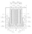
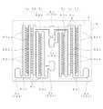
図1に示すように、液体吐出装置1は、キャビティユニット2と、アクチュエータ3とを含んでいる。キャビティユニット2は、液滴を付着させる対象物(被記録媒体)の表面側から、ノズルプレート4、カバープレート5、マニホールドプレート6、二枚のスペーサプレート7、8、ベースプレート9がその順に積層されて構成されている。 As shown in FIG. 1, the
ノズルプレート4には、液体を吐出する複数のノズル41、41、・・・が設けられている。これらの複数のノズル41、41、・・・は、並列に配置された4本のノズル列4a、4b、4c、4dを構成しており、各ノズル列4a、4b、4c、4dにおいて、ノズル41、41、・・・が千鳥状に配置されている。これらのノズル列4a、4b、4c、4dのうちノズルプレート4の縁部に最も近い一列のノズル列4aは、残りの三列のノズル列4b、4c、4dよりも長く形成されている。残りの三列のノズル列4b、4c、4dは同じ長さに形成されている。各ノズル列においてノズル41、41、・・・の配列ピッチは同じである。 The
長いノズル列4aと短いノズル列4b、4c、4dとは、列方向において、一方の端が一致した配置となっている(図3)。そして、他方の端には、短いノズル列4b、4c、4dの列方向延長部分でかつ長いノズル列4aの列方向と直交する位置において、長いノズル列4aと短いノズル列4b、4c、4dとの長さの差によるスペース4Sが形成されている。 The long nozzle row 4a and the
また、ベースプレート9には、液体をノズル41、41、・・・から吐出させるための吐出圧を発生させる圧力室91、91、・・・が、ノズルプレート4の各ノズル41、41、・・・に対してそれぞれ設けられている。これらの圧力室91、91、・・・は、ベースプレート9に、平面視において、ノズル列4a、4b、4c、4dの列方向と直交する方向に長孔を形成することによって設けられ、一端が対応するノズル41、41、・・・と重なるように配置されている。つまり、圧力室91、91、・・・は、ノズル列4a、4b、4c、4dと対応して長短のある列をなし、かつ各列毎に千鳥配列をなしている。 Further, the
また、ベースプレート9には、複数の貫通孔9a、9b、9c、9dが、平面視において、短いノズル列4b、4c、4d(短い三列の圧力室)を挟んで長いノズル列4a(長い列の圧力室)と反対側に、ノズル列4a、4b、4c、4dに平行に設けられている。マニホールドプレート6や二枚のスペーサプレート7、8にも、これと重なる貫通孔6a、6b、6c、6d、7a、7b、7c、7d、8a、8b、8c、8d設けられており、各プレートの貫通孔が連通して供給口10a、10b、10c、10dが形成されている。各供給口10a、10b、10c、10dの入口は、ベースプレート9の上面に取り付けられたフィルタ11によって覆われている。また、各供給口10a、10b、10c、10dの下端は、後述するマニホールド62a、62b、62c、62dに連通している。 The
カバープレート5には、平面視において、ノズルプレート4の各ノズル41、41、・・・に対し重なる位置にそれぞれ、ノズル径よりやや大きめの微小孔51、51、・・・が貫通して設けられている。マニホールドプレート6や二枚のスペーサプレート7、8にも、これと重なる微小孔61、71、81が設けられており、これら微小孔にて、ノズルプレート4の各ノズル41、41、・・・と対応する圧力室91、91、・・・の一端とがそれぞれ連通されている。 In the
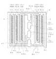
マニホールドプレート6には、図3に示すように、平面視において、圧力室91、91、・・・の各列に沿って延び、且つ、微小孔61、61、・・・の各列の両側にそれぞれ形成されているマニホールド62a、62b、62c、62dが設けられている。そして、各微小孔61、61、・・・の列の両側にあるマニホールド62a、62b、62c、62dを一組とし、それぞれその一方の側のマニホールドに、千鳥配列における一方の側の圧力室91、91、・・・の他端が、後述する連通路72、微小孔82を介して連通されている。なお、微小孔61は、ノズル41と平面視において対応した位置にあるので、以下の説明において、微小孔61をノズル41として説明することもある。 As shown in FIG. 3, the
各組のマニホールド62a、62b、62c、62dの長さは、本来、平面視において、各ノズル列4a、4b、4c、4dの列方向長さとほぼ対応した長さを有しておればよい。しかし、本実施形態では、貫通孔6a、6b、6c、6dから遠い、つまり長いノズル列に対応するマニホールド62aと、近いつまり短いノズル列に対応するマニホールド62dは、ノズル列の長さとほぼ対応した長さを有している。そして、その間のマニホールド4b、4cは、貫通孔から遠いほど長くなっている。これは、後述するように、マニホールドと貫通孔とを接続しやすくするためである。その結果、マニホールドプレート6
における、ノズルプレート4のスペース4Sと対応した位置に、マニホールドの長さの差によるスペース6Sが形成されている。The lengths of the
A space 6S is formed at a position corresponding to the space 4S of the
各組のマニホールド62a、62b、62c、62dは、供給口10a、10b、10c、10dを構成する貫通孔6a、6b、6c、6dにそれぞれ、溝状の接続部63a、63b、63c、63dによって接続されている。つまり、各接続部63a、63b、63c、63dは、一方の端部が、各組のマニホールド62a、62b、62c、62dの端部に接続され、平面視において、その一部が上記スペース6Sを通って、ノズル列4a、4b、4c、4dの列方向と直交する方向に延びている。他方の端部は、各貫通孔6a、6b、6c、6dにそれぞれ接続されている。 The
これらの接続部63a、63b、63c、63dは、貫通孔6a、6b、6c、6dから最も遠くに位置している一組のマニホールド62aから近くに位置しているマニホールド62dを順次、スペース6S側の貫通孔6aから6dに接続している。接続部63b、63c、63dは、貫通孔6a、6b、6c、6dの列と、その列に最も近い位置にあるマニホールド62dとの間において、接続部63aとは反対側であってノズル列の列方向に屈曲した後に、さらに列方向と直交する方向に屈曲して、二番目以降の貫通孔6b、6c、6dに順番に接続している。なお、図3では、接続部63aは、長いノズル列4aと短いノズル列4b、4c、4dとの長さの差部分よりも外に位置しているが、それに連通する供給口10aが、ノズル列の延長方向には位置していないことで、装置の長さを抑えることができている。 These connecting portions 63a, 63b, 63c, and 63d are formed by sequentially connecting the manifold 62d that is located closest to the set of manifolds 62a that are located farthest from the through holes 6a, 6b, 6c, and 6d to the space 6S side. These through holes 6a to 6d are connected. The connection portions 63b, 63c, and 63d are located on the opposite side of the connection portion 63a between the through holes 6a, 6b, 6c, and 6d and the manifold 62d that is closest to the row. After bending in the row direction, it is further bent in a direction perpendicular to the row direction and connected in order to the second and subsequent through holes 6b, 6c, 6d. In FIG. 3, the connecting portion 63a is located outside the length difference between the long nozzle row 4a and the
マニホールドプレート6側のスペーサプレート7には、複数の圧力室91、91、・・・と対応して細長いくぼみ状の連通路72、72、・・・が形成されている。この連通路72、72、・・・の一端部には、貫通孔73、73、・・・が形成されており、連通路72、72、・・・の列ごとに、マニホールドプレート6の共通のマニホールド62a、62b、62c、62dと連通している。 In the
ベースプレート9側のスペーサプレート8は、平面視において、ベースプレート9の各圧力室91、91、・・・の他端及びスペーサプレート7の各連通路72、72、・・・と重なる位置にそれぞれ、連通孔82、82、・・・が形成されている。これらの連通孔82、82、・・・と、スペーサプレート7の各連通路72、72、・・・とによって、各圧力室91、91、・・・と各マニホールド62a、62b、62c、62dとが、それぞれ連通されている。 The
上記スペーサプレート8の連通孔82、82、・・・とスペーサプレート7の連通路72、72、・・・、及び、マニホールプレート6のマニホールド62a、62b、62c、62dと接続部63a、63b、63c、63dとにより、液体を供給口10a、10b、10c、10dから圧力室91、91、・・・へ供給する液体流路12a、12b、12c、12dが構成されている。 The communication holes 82, 82, ... of the
一方、アクチュエータ3は、平面視において、ベースプレート9の各圧力室91、91、・・・と重なる位置に配置した電極31、31、・・・と圧電シートとを交互に積層して構成されている。そして、積層方向の電極31、31間に高電圧を印加することにより、圧電シートに、圧電縦効果による積層方向の歪みを発生させ、圧力室91、91、・・・内の液体をノズル41から吐出させる。なお、図3に点線で表されている四角形の枠は、アクチュエータ3を示している。 On the other hand, the
アクチュエータとしては、上記圧電方式によるもののほか、静電気により振動板を変位させる方式、圧力室内のインクをヒータにより沸騰させる方式などが適用できる。 As the actuator, besides the piezoelectric method, a method of displacing the diaphragm by static electricity, a method of boiling ink in the pressure chamber by a heater, or the like can be applied.
このように構成されている液体吐出装置1は、液体の供給口10a、10b、10c、10dを、平面視において、長いノズル列4aの、その列方向と直交する側に配置しているため、ノズル列4a、4b、4c、4d方向の長さを抑えてコンパク化を図ることができる。また、吐出する液体のうち、使用頻度の高い液体を、長いノズル列4aから吐出させるようにすれば、液体吐出装置1をノズル列と直交する方向(図3のX方向)に被記録媒体に対して走査することで、使用頻度の高い液体を、広い面積に対して効率良く塗布することが可能になる。このように、特定の液体の塗布効率を向上させつつ、コンパクト化を実現するという、相反する課題を同時に解決することができる。この液体吐出装置1を、インクジェット式画像形成装置の記録ヘッドとして用いる場合、ブラックインクを供給口10aから供給し、イエロー、シアン、マゼンタの各インクをそれぞれ各供給口10b、10c、10dから供給するようにすることが、好ましい。このようにすれば、長いノズル列10aからブラックインクが吐出されるため、ブラックインクのみで文字データ等を記録する場合、改行幅(図3のX方向と直交する方向の幅)を大きく取り、記録速度を向上することができるとともに、記録ヘッドのコンパクト化を実現することができる。 Since the
なお、ノズル列4a、4b、4c、4dや液体の供給口10a、10b、10c、10d及び接続部63a、63b、63c、63dの配置は、上記実施形態のものに限定されない。以下に、そのことを説明する。なお、図にはマニホールドプレートのみを示すが、他のプレート4、5、7、8、9のノズル、圧力室、微小孔、連通路、連通孔の配置構成は、マニホールドプレートにおけるマニホールド、微小孔の配置から、一義的に決められるので、説明を省略する。 The arrangement of the
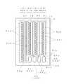
図4に示す実施形態は、ノズル列4a、4b、4c、4dを、供給口10a、10b、10c、10dから離れるにしたがって長くしている。例えば、イエロー、シアン、マゼンタの順でノズル列が長くし、イエローインク、シアンインク、マゼンタインクの順に効率良く対象物の表面に塗布する。マニホールド62a、62b、62c、62d、貫通孔6a、6b、6c、6d、及び接続部63a、63b、63c、63dの配置は、前記実施形態と同様である。 In the embodiment shown in FIG. 4, the
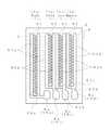
図5から7に示す実施形態は、平面視において、長いノズル列4aの、その列方向と直交する方向の両方の側に短いノズル列4b、4c、4d(図5に示す実施形態の場合さらに4e)がそれぞれ設けられ、さらにその両短いノズル列4b、4c、4d(、4e)に対して長いノズル列4aとは反対側に供給口10a、10b、10c、10d図5に示す実施形態の場合さらに10e)を配置している。 In the embodiment shown in FIGS. 5 to 7, in the plan view, the
即ち、図5に示す実施形態は、長いノズル列4aを中央に配置し、その両側に短いノズル列4b、4cと4d、4eを2列ずつ左右対称に配置し、供給口10a、10b、10c、10d、10eも左右対称に配置している。つまり、ノズル列の長さの差にもとづくスペース6Sが、長いノズル列4aの左右にそれぞれ形成されている。マニホールドプレート6において、長いノズル列4aに対応する微小孔61の両側のマニホールド62aは独立して形成され、それぞれの端部から接続部63a、63aがノズル列の列方向と直交する方向に延び、左右両外側に設けた貫通孔6a、6aにそれぞれ接続している。左側の短いノズル列4b、4cに対応するマニホールド62b、62cは、一方のスペース6Sにおいて左側へ延びる接続部63b、63cを介して左外側に設けた貫通孔6b、6cにそれぞれ接続している。右側の短いノズル列4d、4eに対応するマニホールド62d、62eは、他方のスペース6Sにおいて右側へ延びる接続部63d、63eを介して左外
側に設けた貫通孔6d、6eにそれぞれ接続している。That is, in the embodiment shown in FIG. 5, the long nozzle row 4a is arranged at the center, and the
千鳥配列された長いノズル列4aのうち左側及び右側の列に、それぞれ異なる種類の液
体を供給してもよいが、同じ種類の液体、例えば、ブラックインクを供給してもよい。短いノズル列4b、4c、4d、4eには、それぞれ任意の有彩色のインクが供給される。Different types of liquid may be supplied to the left and right columns of the long nozzle row 4a arranged in a staggered manner, but the same type of liquid, for example, black ink, may be supplied. Arbitrary chromatic ink is supplied to each of the
図6に示す実施形態は、長いノズル列4aの左側に短いノズル列4b、4cを2列、右側に短いノズル列4dを1列配置している。長いノズル列4aにインクを供給するマニホールド62aから接続部63aは、後者の短いノズル列4dの延長方向を直交する方向に延び、すべてのノズル列の右側に設けた供給口10aに接続している。後者の短いノズル列4dにインクを供給するマニホールド62dも同じ側に設けた供給口10dに接続している。また、前者の短いノズル列4b、4cにインクを供給するマニホールド62b、62cは、左側に設けた供給口10b、10cに接続している。 In the embodiment shown in FIG. 6, two
図7に示す実施形態は、図5の実施形態において、短いノズル列のうち1つの千鳥配列4bを、長いノズル列4aの両側に分けて直線状に配置した。それにともない、一組のマニホールド62bも左右に分け、それぞれ左右両外側の供給口10b、10bに接続している。このため、図7に示す実施形態は、図5の実施形態とは、短いノズル列が1列少なくなる。左右に分けたノズル列4bにはそれぞれ異なる液体を供給することもできるが、ノズル列4bを左右で千鳥配列とし、同じインクを供給することで、他の短いノズル列と同様の密度で記録動作させることができる。 In the embodiment shown in FIG. 7, in the embodiment of FIG. 5, one
このようにすべてのノズル列が隣接した配置にすると、アクチュエータ3を1つのまとまった形状にすることができ、キャビティユニット2に対して配置がしやすい。また、キャビティユニット2に対して供給口の大きさを極力大きくすることができる。 When all the nozzle rows are arranged adjacent to each other in this way, the
図8から13に示す実施形態は、平面視において、複数の供給口を挟んで両側に、複数のノズル列のうち短いノズル列、さらにその短いノズル列に対して供給口とは反対側に長いノズル列をそれぞれ設けている。 In the embodiment shown in FIGS. 8 to 13, in plan view, a short nozzle row out of a plurality of nozzle rows on both sides of the plurality of supply ports, and further, the short nozzle row is long on the side opposite to the supply ports. Each nozzle row is provided.
図8に示す実施形態は、供給口10a、10b、10c、10dを縦列配置し、その左側に2列の短いノズル列4b、4cと長いノズル列4aを平行に配置し、右側に1列の短いノズル列4dと長いノズル列4aを平行に配置している。長いノズル列4aは、両最外側にそれぞれ位置することになる。その両ノズル列4aに異なる液体を供給してもよいが、実施形態では、各ノズル列4aに対応するマニホールド62a、62aから延びる接続部63a、63aを、1つの供給口10aに接続して同じ液体を供給するようにしている。 In the embodiment shown in FIG. 8, the supply ports 10a, 10b, 10c, and 10d are arranged in tandem, two
この実施形態では、左側の3列のうち中間のノズル列4bに対応するマニホールド62bから延びる接続部63bは、スペース6Sを通っている。供給口10aに近い内側の2つのノズル列4c、4dに対応するマニホールド62c、62dから延びる接続部63c、63dは、スペース6Sを通っていない。液体吐出装置の長さが大きくなるのは、接続部63c、63dの幅分だけであるので、大きな影響はない。 In this embodiment, the connection portion 63b extending from the manifold 62b corresponding to the
図9に示す実施形態は、縦列配置した供給口10a、10b、10c、10dの両側に、複数のノズル列を、マニホールドプレートの中心Gに対して点対称に配置している。つまり、左側には外側から順に千鳥配列の長いノズル列4a、千鳥配列の短いノズル列4b、直線状配列の短いノズル列4cを、また右側には外側から順に千鳥配列の長いノズル列4a、千鳥配列の短いノズル列4d、直線状配列の短いノズル列4cをそれぞれ他方に対して点対称に配置している。このとき、図9(b)に示すように、千鳥配列の各ノズル列4bと4dは、ノズル41の位置を走査方向Xにおいて一致させ、また、直線状配列の短いノズル列4c、4cはノズル41の位置を、互いに他方のノズルに対して千鳥配列の関係とすることが好ましい。 In the embodiment shown in FIG. 9, a plurality of nozzle rows are arranged symmetrically with respect to the center G of the manifold plate on both sides of the supply ports 10a, 10b, 10c, and 10d arranged in tandem. That is, on the left side, a long nozzle row 4a in a staggered arrangement, a
ノズル列の長さの差にもとづくスペース6Sが、点対称の位置にあるので、短いノズル列4bと4dに対応する各接続部63bと63d及び供給口10bと10bが点対称の位置にある。また同様に、長いノズル列4aと4aに対応する各接続部63aと63a及び供給口10aと10aも点対称の位置にある。しかし、これらは必ずしも完全な点対称の関係にある必要はない。直線状配列の短いノズル列4c、4cに対応するマニホールド62c、62cは、1つの供給口10cに接続部63c、63cを介して接続している。 Since the space 6S based on the difference in the length of the nozzle rows is in a point-symmetrical position, the connection portions 63b and 63d and the supply ports 10b and 10b corresponding to the
このように両側のノズル列4a、4b、4c、4dが点対称になっているため、ベースプレート9の圧力室91の配列も点対称にできる。その結果、圧力室91の配列に対応して電極等を形成するアクチュエータ12は2つ必要になるものの、同形状のものを用いることができる。 Since the
図10に示す実施形態は、図9の実施形態において、短いノズル列4b、4c、4dを、長いノズル列4aの列方向のほぼ中央に寄せ、さらに走査方向Xにおいて互いにほぼ一致した高さに位置させている。 In the embodiment shown in FIG. 10, in the embodiment shown in FIG. 9, the
図11に示す実施形態は、図9の実施形態において、長いノズル列4aの供給口10aと、長いノズル列4aに隣接する短いノズル列4b、4dの供給口10b、10dとを、ノズル列の列方向に対して直交する方向に並べて配置している。これにより、供給口を極力大きくすることができる。 The embodiment shown in FIG. 11 is different from the embodiment shown in FIG. 9 in that the supply port 10a of the long nozzle row 4a and the supply ports 10b and 10d of the
図12に示す実施形態は、図9の実施形態において短いノズル列4b、4c、4d、4eの長さを、長いノズル列4aの半分程度にしている。供給口10a、10b、10c、10d、10eの片側に位置するノズル列4b、4cと、他方の片側に位置するノズル列4d、4eとは、走査方向Xに重ならない位置にある。液体吐出装置と被記録媒体とを、走査方向Xと直交する方向に相対移動(つまり改行)した後、走査方向Xに走査することで、両ノズル列から吐出した液体を重ねることができる。 In the embodiment shown in FIG. 12, the length of the
図13に示す実施形態は、図12の実施形態において短いノズル列の数を増している。 The embodiment shown in FIG. 13 has an increased number of short nozzle rows in the embodiment of FIG.
図14から16に示す実施形態は、平面視において、複数の供給口10a、10b、10c、10dを、短いノズル列4b、4c、4dの延長方向であってかつ長いノズル列4aの、その列方向と直交する方向に配置している。 In the embodiment shown in FIGS. 14 to 16, the plurality of supply ports 10 a, 10 b, 10 c, and 10 d are arranged in the extension direction of the
図14に示す実施形態は、マニホールドプレート6において、前記スペース6Sに、貫通孔6a、6b、6c、6dを、ノズル列と直交する方向に並べている。各貫通孔6a、6b、6c、6dは、対応するマニホールド62a、62b、62c、62dの端部に、接続部63a、63b、63c、63dを介して接続している。ベースプレート9においても、貫通孔6a、6b、6c、6dと対応する位置に貫通孔9a、9b、9c、9dを有するので、長いノズル列4aに対応する圧力室91の一部が、その貫通孔と走査方向Xに並んで位置することになる。このため、アクチュエータ3は、全圧力室に対応して一体に製作しようとすると、図3に点線で示すように、貫通孔9a、9b、9c、9dに対応する部分を切り欠いた形状になる。 In the embodiment shown in FIG. 14, in the
図15に示す実施形態は、図14の実施形態のキャビティユニットを使用し、長いノズル列4aに対応する圧力室と、短いノズ列4b、4c、4dに対応する圧力室とに、別々のアクチュエータ3、3を配置している。このようにすると、各アクチュエータ3、3を単純な矩形にできるので、製作が容易になる。 The embodiment shown in FIG. 15 uses the cavity unit of the embodiment of FIG. 14, and separate actuators are provided for the pressure chambers corresponding to the long nozzle rows 4a and the pressure chambers corresponding to the
図16に示す実施形態は、図14の実施形態において、長いノズル列4aを、短いノズル列4b、4c、4dを挟んで対称に配置している。この場合、アクチュエータ3を、全圧力室に対応して一体に製作してもよいが、各長いノズル列4aに対して2つ、短いノズル列4b、4c、4dに対して1つに分けて製作することもできる。 In the embodiment shown in FIG. 16, in the embodiment of FIG. 14, the long nozzle rows 4a are arranged symmetrically with the
図17に示す実施形態は、図8の実施形態において短いノズル列を1つ減らし、2つの長いノズル列4a、4dに対応する供給口10a、10dを別々に設けている。 In the embodiment shown in FIG. 17, the short nozzle row is reduced by one in the embodiment of FIG. 8, and supply ports 10a and 10d corresponding to the two
図18に示す実施形態は、千鳥配列の長いノズル列4a、直線状配列の長いノズル列4b、千鳥配列の短いノズル列4c、千鳥配列の短いノズル列4d、直線状配列の長いノズル列4e、千鳥配列の長いノズル列4fを平行に備える。これらのノズル列は、短いノズル列4c、4d間の中心線に関して左右対称にある。 The embodiment shown in FIG. 18 includes a staggered long nozzle array 4a, a linear array
両外側の長いノズル列4a、4fへ液体を供給する供給口10a、10fは、平面視において、全ノズル列の左右両外側に設けてある。マニホールドプレート6において、ノズル列4a、4fと平行にあるマニホールド62a、62fは、そこから外方へ延びる接続部63a、63fによって、貫通孔6a、6b(つまり供給口10a、10f)と接続している。短いノズル列4c、4d間に、他のノズル列へ液体を供給する供給口10b、10c、10dが位置する。左右の直線状配列のノズル列4b、4eには、異なる液体を供給してもよいが、この実施形態では、1つの供給口10bに接続している。このため、ノズル列4b、4eは互いに千鳥配列になるようにしている。 The supply ports 10a and 10f for supplying the liquid to the long nozzle rows 4a and 4f on both outer sides are provided on the left and right outer sides of all the nozzle rows in a plan view. In the
この図18の実施形態の液体吐出装置を記録ヘッドとして用いる場合、両外側の長いノズル列4a、4fの一方へブラック染料インク、他方へブラック顔料インクを供給する。また2つの直線状配列のノズル列4b、4eへイエローインク、2つの短いノズル列4c、4dの一方へマゼンタインク、他方へシアンインクを供給する。 When the liquid ejection apparatus of the embodiment of FIG. 18 is used as a recording head, black dye ink is supplied to one of the long nozzle rows 4a and 4f on both outer sides, and black pigment ink is supplied to the other. Further, yellow ink is supplied to the two linearly arranged
さらに他の例として、2つの短いノズル列4c、4dの一方へブラック染料インク、他方へブラック顔料インクを供給し、2つの直線状配列のノズル列4b、4eへイエローインク、両外側の長いノズル列4a、4fの一方へマゼンタインク、他方へシアンインクを供給する。 As yet another example, black dye ink is supplied to one of the two
上記各実施形態の液体吐出装置は、インクジェット式プリンタの記録ヘッドとしてだけでなく、プリント配線基板の配線パターンの形成、液晶カラーフィルタの製造など、各種の液体を液滴にして対象物に付着させる装置に適用できる。 The liquid ejection device according to each of the above embodiments is not only used as a recording head of an ink jet printer, but also forms various liquid droplets and adheres to an object, such as forming a wiring pattern of a printed wiring board and manufacturing a liquid crystal color filter. Applicable to equipment.
1 液体吐出装置
2 キャビティユニット
3 アクチュエータ
4 ノズルプレート
4a〜4d ノズル列
41 ノズル
5 カバープレート
6 マニホールドプレート
7、8 スペーサプレート
9 ベースプレート
91 圧力室
10a〜10d 供給口
12a〜12d 液体流路DESCRIPTION OF
Claims (12)
Translated fromJapanese前記複数のノズル列は並列に設けられ、その列方向に長いノズル列とそれよりも短いノズル列とを含み、
前記各供給口は、前記長いノズル列の、その列方向と直交する側に位置し、前記液体流路の少なくとも1つは、平面視において、前記短いノズル列の列方向延長部分でかつ前記長いノズル列の列方向と直交する位置に形成され、前記供給口に連通していることを特徴とする液体吐出装置。Each of a plurality of nozzle rows composed of a plurality of nozzles for discharging liquid, a plurality of pressure chambers communicating with each of the nozzles to generate discharge pressure, and a row of the pressure chambers corresponding to each of the nozzle rows A liquid ejection device having a plurality of liquid flow paths for supplying the liquid and a plurality of supply ports for supplying the liquid to the liquid flow paths,
The plurality of nozzle rows are provided in parallel, and include a nozzle row long in the row direction and a nozzle row shorter than the nozzle row,
Each of the supply ports is located on a side of the long nozzle row that is orthogonal to the row direction, and at least one of the liquid flow paths is an extended portion of the short nozzle row in the row direction and the long portion in plan view. A liquid ejecting apparatus, wherein the liquid ejecting apparatus is formed at a position orthogonal to the row direction of the nozzle row and communicates with the supply port.
1から9のいずれかに記載の液体吐出装置。The liquid flow path extends along the row of pressure chambers, and temporarily stores the liquid supplied to the pressure chambers. The liquid ejecting apparatus according to claim 1, further comprising a connecting portion that connects the supply port.
そのキャビティユニットのベースプレート上に固定され、前記圧力室内の液体に吐出圧を供給するアクチュエータとを含み、
前記供給口が、前記ベースプレートから前記マニホールドプレートのマニホールドに達するまで積層方向に貫通して設けられ、
前記マニホールドプレートにおいて、前記マニホールドと前記供給口とを接続させる接続部が溝状に形成されていることを特徴とする請求項10に記載の液体吐出装置。The nozzle plate and the base plate formed by laminating a plurality of plates including a nozzle plate in which the nozzle is formed, a base plate in which the pressure chamber is formed, and a manifold plate in which the manifold is formed. A cavity unit disposed at both ends in the stacking direction;
An actuator fixed on a base plate of the cavity unit and supplying discharge pressure to the liquid in the pressure chamber,
The supply port is provided penetrating in the stacking direction until reaching the manifold of the manifold plate from the base plate,
11. The liquid ejection device according to claim 10, wherein in the manifold plate, a connection portion that connects the manifold and the supply port is formed in a groove shape.
Priority Applications (1)
| Application Number | Priority Date | Filing Date | Title |
|---|---|---|---|
| JP2006332450AJP2008143015A (en) | 2006-12-08 | 2006-12-08 | Liquid ejection device |
Applications Claiming Priority (1)
| Application Number | Priority Date | Filing Date | Title |
|---|---|---|---|
| JP2006332450AJP2008143015A (en) | 2006-12-08 | 2006-12-08 | Liquid ejection device |
Publications (1)
| Publication Number | Publication Date |
|---|---|
| JP2008143015Atrue JP2008143015A (en) | 2008-06-26 |
Family
ID=39603713
Family Applications (1)
| Application Number | Title | Priority Date | Filing Date |
|---|---|---|---|
| JP2006332450APendingJP2008143015A (en) | 2006-12-08 | 2006-12-08 | Liquid ejection device |
Country Status (1)
| Country | Link |
|---|---|
| JP (1) | JP2008143015A (en) |
Cited By (3)
| Publication number | Priority date | Publication date | Assignee | Title |
|---|---|---|---|---|
| JP2014148163A (en)* | 2013-01-11 | 2014-08-21 | Canon Inc | Process for producing chip |
| JP2015136893A (en)* | 2014-01-23 | 2015-07-30 | ブラザー工業株式会社 | Liquid jet device |
| JP2015147426A (en)* | 2015-04-15 | 2015-08-20 | ブラザー工業株式会社 | Inkjet head |
- 2006
- 2006-12-08JPJP2006332450Apatent/JP2008143015A/enactivePending
Cited By (3)
| Publication number | Priority date | Publication date | Assignee | Title |
|---|---|---|---|---|
| JP2014148163A (en)* | 2013-01-11 | 2014-08-21 | Canon Inc | Process for producing chip |
| JP2015136893A (en)* | 2014-01-23 | 2015-07-30 | ブラザー工業株式会社 | Liquid jet device |
| JP2015147426A (en)* | 2015-04-15 | 2015-08-20 | ブラザー工業株式会社 | Inkjet head |
Similar Documents
| Publication | Publication Date | Title |
|---|---|---|
| US7607760B2 (en) | Ink-jet printing head having a plurality of actuator units and/or a plurality of manifold chambers | |
| JP4940672B2 (en) | Inkjet recording head | |
| US7284841B2 (en) | Ink-jet recording head and ink-jet recording apparatus | |
| US6554409B2 (en) | Ink-jet recording head | |
| US8047634B2 (en) | Injet jet stack external manifold | |
| US7125097B2 (en) | Ink-jet printing head in which each passage between pressure chamber and nozzle includes horizontally extending portion | |
| JP2008143015A (en) | Liquid ejection device | |
| US20050024442A1 (en) | Inkjet printing head | |
| JP4810908B2 (en) | Inkjet head | |
| JP4967704B2 (en) | Method for manufacturing liquid droplet ejecting head | |
| JP4857986B2 (en) | Ink jet printer and head for ink jet printer | |
| JP2001219560A (en) | Ink jet recording head | |
| JP4051541B2 (en) | Inkjet printer head | |
| JP4161203B2 (en) | Inkjet printer head | |
| JP5141062B2 (en) | Droplet discharge head | |
| JP4433157B2 (en) | Inkjet printer head | |
| JP4385667B2 (en) | An ink jet recording head and a printing apparatus having the ink jet recording head. | |
| JP2005231038A (en) | Inkjet head | |
| JP2005059551A5 (en) | ||
| JP3931972B2 (en) | Inkjet printer head | |
| JPS60232967A (en) | Ink jet head | |
| JPH09511465A (en) | Ink jet recording device | |
| JP4639610B2 (en) | Inkjet head design method and inkjet head | |
| JP5158161B2 (en) | Inkjet head | |
| JP2000318149A (en) | Inkjet head |