JP2008137640A - Automatic bicycle storage system, bicycle for the system and locking station for the system - Google Patents
Automatic bicycle storage system, bicycle for the system and locking station for the systemDownload PDFInfo
- Publication number
- JP2008137640A JP2008137640AJP2007243042AJP2007243042AJP2008137640AJP 2008137640 AJP2008137640 AJP 2008137640AJP 2007243042 AJP2007243042 AJP 2007243042AJP 2007243042 AJP2007243042 AJP 2007243042AJP 2008137640 AJP2008137640 AJP 2008137640A
- Authority
- JP
- Japan
- Prior art keywords
- bicycle
- storage system
- fixing device
- fixed head
- automatic storage
- Prior art date
- Legal status (The legal status is an assumption and is not a legal conclusion. Google has not performed a legal analysis and makes no representation as to the accuracy of the status listed.)
- Pending
Links
- 238000004891communicationMethods0.000claimsdescription23
- 230000000452restraining effectEffects0.000claimsdescription19
- 238000012423maintenanceMethods0.000claimsdescription14
- 230000002093peripheral effectEffects0.000claimsdescription4
- 230000002452interceptive effectEffects0.000description8
- 238000000034methodMethods0.000description4
- 230000008878couplingEffects0.000description2
- 238000010168coupling processMethods0.000description2
- 238000005859coupling reactionMethods0.000description2
- 238000001514detection methodMethods0.000description2
- 238000004873anchoringMethods0.000description1
- 230000000295complement effectEffects0.000description1
- 230000000694effectsEffects0.000description1
- 238000009434installationMethods0.000description1
- 230000005389magnetismEffects0.000description1
- 230000001629suppressionEffects0.000description1
- 238000003466weldingMethods0.000description1
Images


Classifications
- B—PERFORMING OPERATIONS; TRANSPORTING
- B62—LAND VEHICLES FOR TRAVELLING OTHERWISE THAN ON RAILS
- B62H—CYCLE STANDS; SUPPORTS OR HOLDERS FOR PARKING OR STORING CYCLES; APPLIANCES PREVENTING OR INDICATING UNAUTHORIZED USE OR THEFT OF CYCLES; LOCKS INTEGRAL WITH CYCLES; DEVICES FOR LEARNING TO RIDE CYCLES
- B62H5/00—Appliances preventing or indicating unauthorised use or theft of cycles; Locks integral with cycles
- B62H5/02—Appliances preventing or indicating unauthorised use or theft of cycles; Locks integral with cycles for locking the steering mechanism
- B62H5/06—Appliances preventing or indicating unauthorised use or theft of cycles; Locks integral with cycles for locking the steering mechanism acting on the front wheel fork or steering head tube
- B—PERFORMING OPERATIONS; TRANSPORTING
- B62—LAND VEHICLES FOR TRAVELLING OTHERWISE THAN ON RAILS
- B62H—CYCLE STANDS; SUPPORTS OR HOLDERS FOR PARKING OR STORING CYCLES; APPLIANCES PREVENTING OR INDICATING UNAUTHORIZED USE OR THEFT OF CYCLES; LOCKS INTEGRAL WITH CYCLES; DEVICES FOR LEARNING TO RIDE CYCLES
- B62H3/00—Separate supports or holders for parking or storing cycles
- B62H3/02—Separate supports or holders for parking or storing cycles involving means for gripping the cycle by the handlebars or by the upper part of the frame
- B—PERFORMING OPERATIONS; TRANSPORTING
- B62—LAND VEHICLES FOR TRAVELLING OTHERWISE THAN ON RAILS
- B62H—CYCLE STANDS; SUPPORTS OR HOLDERS FOR PARKING OR STORING CYCLES; APPLIANCES PREVENTING OR INDICATING UNAUTHORIZED USE OR THEFT OF CYCLES; LOCKS INTEGRAL WITH CYCLES; DEVICES FOR LEARNING TO RIDE CYCLES
- B62H5/00—Appliances preventing or indicating unauthorised use or theft of cycles; Locks integral with cycles
- B—PERFORMING OPERATIONS; TRANSPORTING
- B62—LAND VEHICLES FOR TRAVELLING OTHERWISE THAN ON RAILS
- B62H—CYCLE STANDS; SUPPORTS OR HOLDERS FOR PARKING OR STORING CYCLES; APPLIANCES PREVENTING OR INDICATING UNAUTHORIZED USE OR THEFT OF CYCLES; LOCKS INTEGRAL WITH CYCLES; DEVICES FOR LEARNING TO RIDE CYCLES
- B62H3/00—Separate supports or holders for parking or storing cycles
- B62H2003/005—Supports or holders associated with means for bike rental
Landscapes
- Engineering & Computer Science (AREA)
- Mechanical Engineering (AREA)
- Lock And Its Accessories (AREA)
Abstract
Description
Translated fromJapanese本発明は、自転車自動格納システム、前記システムのための自転車、及び前記システムのためのロックステーションに関する。 The present invention relates to a bicycle automatic storage system, a bicycle for the system, and a lock station for the system.
特に、本発明は、複数の自転車と複数の固定式ロックステーションとを含む自転車自動格納システムであって、各自転車は、一方の固定装置が自転車に接続され、且つ、他方の固定装置がロックステーションに接続される第1の固定装置及び第2の固定装置を介して、長手方向に沿ってロックステーション上にロック可能な自転車自動格納システムに関する。 In particular, the present invention is an automatic bicycle storage system including a plurality of bicycles and a plurality of fixed lock stations, each bicycle having one fixing device connected to the bicycle and the other fixing device being a lock station. The present invention relates to a bicycle automatic storage system that can be locked on a lock station along a longitudinal direction via a first fixing device and a second fixing device connected to each other.
そのような自転車格納システムは、例えば自転車を使用者に使用できるようにするために、自転車の使用者の識別及びおそらく対話型端末装置(interactive terminal)と共に使用料の支払いを必要とするように使用されることができる。 Such a bicycle storage system may be used, for example, to require the use of a bicycle with the user's identification and possibly an interactive terminal to make the bicycle available to the user. Can be done.
特許文献1は、固定装置の1つが他の固定装置のラッチ式キャッチ(latch catch)に固定することによってロックするロック要素を含む自転車格納システムを開示する。 U.S. Patent No. 6,057,031 discloses a bicycle storage system that includes a locking element that locks by locking one of the locking devices to a latch catch of another locking device.
そのような格納システムにおいて、ロック要素及びラッチ式キャッチは、固定方向として同一の方向に実質的に延在している。 In such a storage system, the locking element and the latching catch extend substantially in the same direction as the fixed direction.
しかしながら、そのような実施形態は、実行すること及びロックステーション上で自転車をロックすることに関して、問題をもたらす。 However, such embodiments present problems with respect to performing and locking the bicycle on the lock station.
実際に、ロック要素とラッチ式キャッチとの間の延在される接触面のために、例えばグラウンドの不規則性に関連され、グラウンド上でロックステーションを設置することに関連され、自転車のタイヤの収縮に又はロックステーションに関して自転車の不適切な方向に関連された相対的な垂直方向のシフト又は角度のシフトは、ラッチ式キャッチにロック要素の先端部分を固定することが可能にすることはない。その後、使用者は、適合される位置及び方向を見つけるために自転車を移動し、ロックステーション上に自転車を載置することを複雑にする。 In fact, because of the extended contact surface between the locking element and the latching catch, for example, related to ground irregularities, related to installing a locking station on the ground, Relative vertical or angular shifts associated with retraction or improper orientation of the bicycle with respect to the lock station do not allow the tip portion of the locking element to be secured to the latching catch. The user then moves the bicycle to find the position and orientation to be matched, complicating placing the bicycle on the lock station.
さらに、ラッチ式キャッチ内にロック要素を部分的に固定した後で、シフトは、特に角度の、ラッチ式キャッチ内でロック要素のロックを得るために十分な固定を可能にすることはない状態で留まることができる。従って、使用者が自転車をロックしないでロックステーション上で傾斜している自転車の状態であるリスクが存在する。
本発明は、そのような問題を解決することを目的とする。 The present invention aims to solve such a problem.
そのような効果のために、本発明は、上記に述べた種類の自転車自動格納システムを提案する:
−第2の固定装置は、略垂直な固定ヘッド部を含む。
−第1の固定装置は、以下に示す要素を含む:
・フォークは、短手方向のベースと、固定ヘッド部を受容するように適合され、垂直方向に開口された受容空間を形成するために、長手方向に沿って略同一の水平面内でベースから延在し、互いから離間されている2つの横向きのブランチを有する。
・ロック要素は、ブランチとベースとの間の固定ヘッド部を保持するように、前記ロック要素が固定ヘッド部と干渉しない収納位置と、前記ロック要素が少なくとも部分的に受容領域内に延在しているロック位置との間でフォークに相対的に移動されることができる。
−垂直方向の間隙は、第1の固定装置と第2の固定装置との間に存在している。For such an effect, the present invention proposes a bicycle automatic storage system of the kind described above:
The second fixing device comprises a substantially vertical fixing head;
The first fastening device comprises the following elements:
The fork is adapted to receive the base in the short direction and the fixed head part and extends from the base in substantially the same horizontal plane along the longitudinal direction to form a receiving space opened vertically. And has two lateral branches that are spaced apart from each other.
A locking position in which the locking element does not interfere with the fixed head so that the locking element holds the fixed head between the branch and the base; and the locking element extends at least partially into the receiving area It can be moved relative to the fork between the locked position.
A vertical gap exists between the first fixing device and the second fixing device;
この方法において、固定ヘッド部は、接触面の範囲を制限することを可能にするために、受容領域において固定方向に対して略垂直な方向に沿って延在する。そのようなシステムは、ロックステーション上で自転車を載置し、ロックすることを容易にする垂直方向のシフト及び角度のシフトを可能にすることによって、固定装置のロックを得ることを可能にする。 In this way, the fixed head part extends along a direction substantially perpendicular to the fixing direction in the receiving area in order to be able to limit the range of the contact surface. Such a system makes it possible to obtain a locking of the anchoring device by allowing a vertical shift and an angle shift that make it easier to place and lock the bicycle on the lock station.
特定の実施形態において、自転車自動格納システムは、可能な限り相補的な方法において、以下の配置を有することができる。
−短手方向の間隙は、長手方向に対して垂直とされる水平方向に沿って第1の固定装置と第2の固定装置との間に存在している。
−長手方向の間隙は、前記長手方向に沿って第1の固定装置と第2の固定装置との間に存在している。
−第1の固定装置及び第2の固定装置は、少なくとも±2cmの垂直方向の間隙を有した状態で、固定ヘッド部と受容領域との間に固定可能なように適合される。
−固定ヘッド部は、略円筒形の直線状ロッドを形成する。
−第2の固定装置は、固定ヘッド部が第1の縁部に堅固に形成された状態で、一方の縁部を他方の縁部に対して相対的に長手方向に沿って移動させる第1の短手方向の縁部及び第2の短手方向の縁部を有し、略垂直に延在している中空体を含んでいる。前記中空体は、固定ヘッド部と第2の縁部との間で長手方向に対して垂直に測定される短手方向の寸法が、固定ヘッド部と第2の縁部との間で垂直に延在している横方向の固定用窪み部を形成するように固定ヘッド部及び第2の縁部の周辺領域における短手方向の寸法よりも小さい領域を有する。
−ロック要素は、略垂直な回転軸を中心としてフォーク上で回動するように取り付けられる。
−ロック要素は、薄いプレートと、プレートの両側部上で回転軸に対して同軸的にに延在している中心シャフトとを含み、前記プレートが前記プレートの縁部に位置する凹所を備え、固定ヘッド部に固定するように適合される。
−凹所は、抑制縁部及び支持縁部を含み、抑制縁部は前記プレートの収納位置において受容領域の外側に位置し、前記プレートのロック位置において前記ベースの反対側に、前記固定ヘッド部に面している前記受容領域に延在し、前記指示縁部は、収納位置からロック位置へプレートを切り替えるように、固定ヘッド部と接触するために適合される。
−第1の固定装置は、ロック要素の移動を制御するためのシステムを含み、制御システムはロック位置にロック要素を維持する第1の位置と、収納位置にロック要素を維持する第2の位置との間で移動可能である。
−制御システムは、中央の関節軸を中心として回転する際に、互いに回動可能に接続されている第1の接続ロッド及び第2の接続ロッドを含み、第1の接続ロッド及び第2の接続ロッドの自由端部のそれぞれは、前記第1の位置において、前記接続ロッドが位置合わせされ、且つ、前記第2の位置において、前記接続ロッドが接続ロッド間に前記中央の関節軸に上にエルボを形成するように、側方に位置する関節軸を中心として回動可能に接続要素及びフォークに接続される。
−関節軸は、垂直方向に延在している。
−制御システムは、前記ロッドが前記第1の位置に位置合わせされた状態を維持し、且つ、前記接続ロッドが位置合わせされない場合には前記接続ロッドを第2の位置へ向けて接続ロッドを弾性的に付勢するように適合された弾性要素を含む。
−前記制御システムは、前記接続ロッドのうち一つの前記接続ロッドに結合される維持要素をさらに含み、前記維持要素は、前記接続ロッドが位置合わせされた場合に、前記フォークの維持面に接続され、前記接続ロッドが位置合わせされない場合に、前記維持面から離隔される。
−維持要素は、永久磁石であり、前記フォークの前記維持面は、磁性を有している。
−制御システムは、維持面から維持要素を離隔するように適合された維持要素の放出要素をさらに含む。
−第1の固定装置は、ロック要素が取り付けられるハウジングを形成している閉鎖されたボックスをさらに含む。
−第1の固定装置は、ロック要素を制御している第1の電気回路を含む。
−第1の固定装置は、第1の電気回路に接続され、且つ、ロック要素のロック位置を示す信号を送信するように適合されている少なくとも1つのセンサーを含む。
−第1の固定装置は、第1の電気回路に接続され、且つ、受容領域において固定ヘッド部の存在を示す信号を送信するように適合されている少なくとも1つのセンサーを含む。
−第1の固定装置は、そのロック位置からロック要素を離隔するように適合されている電気的なアンロック要素を含む。
−第2の固定装置は、第2の電気回路を含み、第1の固定装置及び第2の固定装置は、自転車がロックステーションにロックされた場合に、前記第1の電気回路及び前記第2の電気回路を通信状態にするように適合されている通信インターフェースを含んでいる。
−通信インターフェースは、互いに面している電気的接点を含む。
−少なくとも幾つかの前記電気的接点は、自転車とロックステーションとの相対的な垂直方向位置について、第1の電気回路と第2の電気回路との間で通信可能となるように垂直方向に延在している。
−通信インターフェースは、非接触式インターフェースである。
−第1の固定装置は、自転車に接続され、第2の固定装置はロックステーションに接続される。
−自転車は、その一端が前記自転車に固定され、且つ、その他端が前記第1の固定装置の前記受容領域内にロック可能なように適合されている補助固定ヘッド部を備えたピンを含むケーブルを含んでいる盗難防止用の装置を含む。In certain embodiments, the bicycle automatic storage system can have the following arrangement in a manner that is as complementary as possible.
The gap in the lateral direction exists between the first fixing device and the second fixing device along a horizontal direction perpendicular to the longitudinal direction.
A longitudinal gap exists between the first fixing device and the second fixing device along the longitudinal direction;
The first fixing device and the second fixing device are adapted to be fixable between the fixed head part and the receiving area with a vertical gap of at least ± 2 cm;
The fixed head part forms a substantially cylindrical linear rod;
The second fixing device is configured to move the one edge portion along the longitudinal direction relative to the other edge portion in a state in which the fixing head portion is firmly formed on the first edge portion; And a hollow body extending substantially perpendicularly and having a second lateral edge and a second lateral edge. The hollow body has a transverse dimension measured perpendicularly to the longitudinal direction between the fixed head portion and the second edge portion, and is perpendicular to the fixed head portion and the second edge portion. It has a region smaller than the dimension in the lateral direction in the peripheral region of the fixed head portion and the second edge portion so as to form an extending lateral fixing recess portion.
The locking element is mounted to rotate on the fork about a substantially vertical axis of rotation;
The locking element comprises a thin plate and a central shaft extending coaxially with respect to the axis of rotation on both sides of the plate, the plate comprising a recess located at the edge of the plate Adapted to be fixed to the fixed head portion.
The recess includes a restraining edge and a support edge, the restraining edge being located outside the receiving area in the stowed position of the plate and on the opposite side of the base in the locking position of the plate The indicator edge is adapted to contact the fixed head so as to switch the plate from the stowed position to the locked position.
The first fixing device comprises a system for controlling the movement of the locking element, the control system maintaining a locking element in the locked position and a second position maintaining the locking element in the stowed position; It is possible to move between.
The control system comprises a first connecting rod and a second connecting rod that are pivotally connected to each other when rotating about a central joint axis, the first connecting rod and the second connecting rod; Each of the free ends of the rods is in the first position where the connecting rod is aligned and in the second position the connecting rod is elbowed up between the connecting rods to the central joint axis. So as to be pivotable about the joint shaft located on the side, and connected to the connecting element and the fork.
The joint axis extends in the vertical direction;
The control system maintains the rod in alignment with the first position and, if the connecting rod is not aligned, elasticates the connecting rod towards the second position A resilient element adapted to be biased automatically.
The control system further comprises a retaining element coupled to one of the connecting rods, the retaining element being connected to the retaining surface of the fork when the connecting rod is aligned; When the connecting rod is not aligned, it is separated from the maintenance surface.
The maintenance element is a permanent magnet, and the maintenance surface of the fork is magnetic;
The control system further comprises a release element of the maintenance element adapted to separate the maintenance element from the maintenance surface;
The first securing device further comprises a closed box forming a housing to which the locking element is mounted;
The first securing device comprises a first electrical circuit controlling the locking element;
The first securing device comprises at least one sensor connected to the first electrical circuit and adapted to transmit a signal indicative of the locking position of the locking element;
The first fixing device comprises at least one sensor connected to the first electrical circuit and adapted to transmit a signal indicating the presence of the fixed head in the receiving area;
The first locking device comprises an electrical unlocking element adapted to separate the locking element from its locked position;
The second fixing device comprises a second electrical circuit, wherein the first fixing device and the second fixing device are configured such that when the bicycle is locked to a lock station, the first electrical circuit and the second electrical circuit; A communication interface adapted to bring the electrical circuit into communication.
The communication interface comprises electrical contacts facing each other;
At least some of the electrical contacts extend vertically so as to be able to communicate between the first electrical circuit and the second electrical circuit with respect to the relative vertical position of the bicycle and the lock station; Exist.
The communication interface is a contactless interface;
The first fixing device is connected to the bicycle and the second fixing device is connected to the lock station;
The bicycle comprises a pin with a pin with an auxiliary fixing head, one end of which is fixed to the bicycle and the other end is adapted to be locked in the receiving area of the first fixing device; Including anti-theft devices.
さらに、本発明は、上記に記載のような自転車自動格納システムのための自転車に関する。 The invention further relates to a bicycle for an automatic bicycle storage system as described above.
さらに、本発明は、上記に記載されるような自転車自動格納システムのためのロックステーションを提案する。 Furthermore, the present invention proposes a lock station for a bicycle automatic storage system as described above.
本発明の他の目的及び利点は、添付される図面を参照して提供される以下の説明を読むときに現れるだろう。 Other objects and advantages of the present invention will appear when reading the following description provided with reference to the accompanying drawings.
図面において、同一の参照符号は、同一の要素又は類似の要素を示す。 In the drawings, identical reference numbers indicate identical or similar elements.
図1は、格納システムを使用者に利用させるために、特に公道上の複数の自転車1を収容することを可能にしている自転車自動格納システムを示す。 FIG. 1 shows an automatic bicycle storage system that makes it possible to accommodate a plurality of
示された例において、各自転車1は、特にフレーム上で回動するように取り付けられた2つの略同一平面にあるホイール3を介して地面に載置されるフレーム2を含む。 In the example shown, each
図1において、自動格納システムは、例えばキーボード5、画面6、及び電子カードのリーダーを含むユーザーインターフェースを備える対話式端末装置4(interactive terminal)を含んでいる自転車のための格納グラウンドを含む。対話式端末装置4をそれぞれ含んでいる複数の格納グラウンドを含むことは、システムのために設けることが可能である。 In FIG. 1, the automatic storage system includes a storage ground for a bicycle including an interactive terminal 4 with a user interface including, for example, a
対話式端末装置4は、埋められたワイヤー結線8又は特に遠隔な任意の別の適切な結合手段によって、例えば公道上の地面に固定されたロックターミナルの形態である場合がある複数のロックステーション9に接続されている。 The interactive terminal device 4 comprises a plurality of
残りの説明において、ロックステーション9が固定されたグラウンド表面は、特に格納グラウンド表面は、水平面Phを画定する。水平面Phの2方向は、例えば自転車1が実質的に延在する方向に対応する長手方向L及び長手方向Lに垂直である短手方向Tを画定される。水平面に対して垂直である垂直方向Vも画定される。長手方向L及び垂直方向Vを含んでいる垂直方向の平面、及び短手方向T及び垂直方向Vを含んでいる短手方向の平面も画定される。 In the rest of the description, the ground surface to which the
さらに、“前方(front)”及び“後方(rear)”という用語は、自転車1の標準的な移動方向に関係することを理解されたい。 Furthermore, it should be understood that the terms “front” and “rear” relate to the standard direction of movement of the
自転車自動格納システムにおいて、各自転車1は、一方を自転車1に接続され、他方をロックステーション9に接続される第1の固定装置11及び第2の固定装置10を介して、ロックステーション9の一つにロック可能である。 In the automatic bicycle storage system, each
本明細書は、第1の固定装置11が自転車1及びロックステーション9に接続された第2の固定装置10に接続される格納システムについて以下に説明するものである。 The present description describes the storage system in which the
しかしながら、図示されていない代替形態として、第1の固定装置11がロックステーション9に接続され、第2の固定装置10が自転車1に接続される格納システムを提供することができる。 However, as an alternative not shown, it is possible to provide a storage system in which the
その後、各自転車1は、格納状態及び使用状態を採用することができる。 Thereafter, each
格納状態において、自転車1は、互いに対して固定されている固定装置10,11と共にロックステーション9にロックされる。その結果、自転車1は、ロックステーション9上で載置することによって、又はフレーム2上で取り付けられた支持脚を用いて、そのホイール3上で垂直位置内に維持されることができる。 In the retracted state, the
使用状態において、自転車1はロックステーション9上でロックされず、使用者によって借りられることができる。 In use, the
本発明によれば、第2の固定装置10が固定装置を形成し、第1の固定装置11がロック装置を形成するように設けられる。 According to the invention, the
図面において、第2の固定装置10は、略垂直に延在し、且つ、ロックステーション9の横方向の表面に結合される支持部12に取り付けられる中空体13を含むことができる。 In the drawing, the
特に、中空体13は、長手方向Lと一致して他に関して一を移動させる第1の短手方向の縁部13a及び第2の短手方向の縁部13bを含むことができる。中空体13は、例えば、略垂直な軸に沿って略円筒形の直線状のロッドを形成している固定ヘッド部14を含み、第1の縁部13aに堅固に結合される。中空体13は、固定ヘッド部14と第2の縁部13bとの間で長手方向に垂直に測定された短手方向の寸法Drの領域を有し、短手方向の寸法Drは固定ヘッド部14の周辺領域及び第2の縁部13bの周辺領域において、それぞれ短手方向の寸法Dt,Db未満である。従って、その領域は、固定ヘッド部14を超えて、固定ヘッド部14と第2の縁部13bとの間に垂直に延在している横方向の固定用窪み部13cを形成する。In particular, the
第2の固定装置10の支持部12は、特に電気回路と、少なくとも1つの通信インターフェース15と、を含むことができる。図面において、第2の固定装置10の通信インターフェース15は、例えば垂直方向に延在している2つの平行な電気的接点15を含む。 The
従って、ロックステーションは、格納グラウンド上でその設置を容易にする単純な構造を有する。 Thus, the lock station has a simple structure that facilitates its installation on the storage ground.
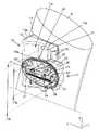
第1の固定装置11は、フレーム2の固定領域に固定されるクローズドケース16を含む。 The
フレーム2の固定領域は、短手方向にフレーム2を交差する1つ又は複数の、図3に示される実施形態においては2つである、中空な留め具シリンダー17を含むことができ、先端部18がフレーム2の側部から突出する。留め具シリンダー17は、溶接又は別の方法によってフレーム2に固定されることができる。 The fixing region of the
ケース16は、留め具シリンダー17の端部分18の一つがそれぞれ受容している2つの凹所19を備える。さらに、ネジ穴20は、図示されない留め具要素、例えばネジ又はボルトが各止め具シリンダー17内に配置されることができ、自転車1のフレーム2にロック装置11のケース16を固定するために対応しているネジ穴20と共にネジを介して協働するそのような方法で各凹所19の底部から延在することができる。ケースの向かい側に、カバー21は、留め具要素のヘッド部を覆うために達することができる。 The
第1の固定装置11は、フォークとケース16との間に延在している、例えば、ネジ、ボルト、プロングロック(prong locks)または別のもののような留め具要素によってケース16に取り付けられたフォークも含む。 The
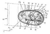
フォークは、短手方向のベース22と、互いから離隔された2つの横方向のブランチ23(branches)を有している。内部ブランチ23aはフレーム2の近傍に位置し、外部ブランチ23bはフレーム2から所定距離で離隔されている。横方向のブランチ23a,23bは、固定ヘッド部14を受容するように適合された垂直方向に開口された受容領域24を形成するために、略同一水平面内でベース22から長手方向Lに沿って前面へ延在している。 The fork has a
図示された実施形態において、ケース16は、ロック要素が取り付けられたハウジングを形成する。 In the illustrated embodiment, the
例えば、ロック装置は、略垂直な回転軸Aを中心としてフォーク上で回動するように取り付けられている薄いプレート25を含むことができる。このために、ロック装置は、プレート25の両側部上で回転軸Aの同軸的に延在することが可能であるように、プレート25の中央ボア27上で取り付けられた中央シャフト26も含むことができる。 For example, the locking device can include a
しかしながら、図示されていない実施形態において、プレート25は、垂直以外の方向を有している回転軸Aを中心として回動するように取り付けられることができることは提供される。もう1つの方法として、ロック装置11のフォーク上で平行移動するように取り付けられたロック要素は、提供されることができる。 However, in an embodiment not shown, it is provided that the
図10及び図11において、プレート25は、プレート25の縁部で存在する略U字状である凹所28と共に備えている。凹所は、互いに面している抑制縁部29及び支持縁部30を含む。支持縁部29は増大している曲率半径を有することができる一方、抑制縁部29の曲率半径は略一定である。 10 and 11, the
凹所28の向かい側に、プレート25は、交差ホール31(crossing hole)と、交差ホール31のそれぞれの側部上で回転軸Aに相対的に径方向に延在するプレートの移動制限のための2つの表面32,33を有する。交差ホール31と支持縁部30との間に配置された制限表面32の一つは、抑制縁部29に略平行である。交差ホールと抑制縁部29との間に位置付けられた他の制限表面33は、支持縁部30に略平行である。 Opposite the
薄いプレート25は、特に図7〜9に示される収納位置と、特に図4〜6に示されるロック位置との間で相対的にフォークを移動可能である。 The
プレート25の収納位置において、抑制縁部29は、例えばフォークの内部ブランチ23a内に実質的に位置付けられた受容領域24の外側に配置されている。この位置において、プレート25は、固定ヘッド部14と干渉することはない。 In the stowed position of the
抑制縁部29、支持縁部30及び移動制限表面32,33の配置は、プレート25の収納位置において、支持縁部30が受容領域24に少なくとも部分的に延在することができるように、その収納位置からそのロック位置にプレート25を切り替えるように固定ヘッド部14と共に接触することができるように特に提供される。 The arrangement of the restraining
ロック位置において、抑制縁部29が受容領域24に少なくとも部分的に延在する。さらに、抑制縁部29は、固定ヘッド部14を固定することができ、横方向のブランチ23a,23b間で固定ヘッド部を保持することができるように、短手方向のベース22の反対側に、固定ヘッド部14に面している固定用窪み部13c内に位置付けられる。支持縁部30に平行である移動制限表面33は、抑制縁部が受容領域24に少なくとも部分的に延在することができるようにフォークの表面に接触する状態になる。 In the locked position, the restraining
固定装置10,11の相対的な位置を容易にするために、固定ヘッド部14の垂直方向の寸法dtは、固定装置10,11間で垂直方向の間隙を存在するように、ブランチ23a,23bの垂直方向の寸法dbよりも大きい。さらに、ブランチ23a,23bの垂直方向の寸法dbは、抑制縁部29の垂直方向の寸法dsよりもよりより大きくなることができる。In order to facilitate the relative position of the fixing
さらに、図6に示されるように、短手方向の間隙JTは、短手方向Tに沿って固定装置10,11の間に存在することができる。特に、内部ブランチ23aと外部ブランチ23bとの間の間隙は、例えば固定ヘッド部14と外部ブランチ23bとの間、及び固定ヘッド部14と内部ブランチ23aとの間にそれぞれの短手方向の間隙JT1及びJT2の和によって、形成される短手方向の間隙と共に固定ヘッド部14を受容することができる。Further, as shown in FIG. 6, the gap JT in the short direction may exist between the fixing
さらに、長手方向の間隙JLは、特に長手方向Lによる固定装置10,11の間で存在することができる。特に、プレート25がロック位置であるとき、抑制縁部29とベース22との間の距離は、受容領域24が固定ヘッド部14とベース22との間、及び固定ヘッド部14と抑制縁部29との間にそれぞれ長手方向の間隙JL1及びJL2の和によって形成された長手方向の間隙JLと共に固定ヘッド部14を保持することができるようである。Further, the gap JL in the longitudinal direction can in particular be present between the longitudinal direction L by the fixing
別々である、又は組み合わせであるそのような配置は、第1の固定装置11と第2の固定装置との間の相対的な位置合わせの許容範囲及び方向付けの許容範囲を増加することを可能にさせる。 Such an arrangement, which is separate or in combination, can increase the relative alignment tolerance and orientation tolerance between the
例えば、ラッチは、少なくとも±2cmの垂直方向の間隙と共に固定ヘッド部14と受容領域24との間に設けられることができる。特に、決定された位置に対して相対的な±約3mmの垂直方向のシフト及び決定された方向に対して相対的な±約10°よりも大きいそれぞれの方向の中心とした角度シフトと共に第2の固定装置10上で第1の固定装置11のロックを得るように設けられることができる。 For example, a latch can be provided between the fixed
第1の固定装置11は、その収納位置とそのロック位置との間でプレート25の移動制御のシステムを含むことができる。制御システムは、第1の位置と第2の位置との間を移動することができる。 The
このために、制御システムは、回転軸Aに平行な中央の関節軸B1を中心として回転する際に、互いに回動可能に接続されている第1の接続ロッド34及び第2の接続ロッド35を含むことができる。第1の接続ロッド34の自由端部は、交差ホール31に取り付けられたシャフトを使用する例によって、回動しているプレートに第1の横方向の関節軸B2の中心として回動可能に接続されていることができる。そして、第2の接続ロッド35の自由端部は、第2の横方向の関節軸B3の中心としてフォークのベース22に回転可能に接続されていることができる。 For this purpose, when the control system rotates about the central joint axis B1 parallel to the rotation axis A, the control system connects the
関節軸Bと接続ロッド34,35の長さとの間の間隙は、第1の位置において、接続ロッド34,35が長手方向Lに沿って同一の略垂直な平面内に位置付けられ、(図4〜図6のように)プレート25がロック位置にあるとき、プレート25の回転を妨げるように設けられる。そして、接続ロッド34,35が位置合わせされない場合に、接続ロッドは、接続ロッド自身の間に中央の関節軸B1上でエルボ36を形成し、互いに相対的に移動されることができ、(図7〜図9のように)そのロック位置から離隔されることができるプレート25の回転を可能にする。 The gap between the joint axis B and the length of the connecting
それ故に、制御システムは、接続ロッドが位置合わせされず、収納位置でプレート25を維持するときに、プレート25に取り付けられる垂直方向のパイロットポイント37と接続ロッドを第2の位置に向かって弾性的に付勢するフォークとの間に取り付けられるばね38のような弾性要素を含むことができる。 Therefore, the control system elastically moves the
そのような制御システムは、第1の位置及び第2の位置が安定するシステムを形成する。 Such a control system forms a system in which the first position and the second position are stable.
図示されていない代替形態において、接続ロッド及び関節軸Bの配置は、以前に描かれている以外で設けられることができる。 In an alternative not shown, the arrangement of the connecting rod and the joint axis B can be provided other than previously depicted.
制御システムは、接続ロッドが位置付けられるとき、例えば磁性でフォークの維持面40に接続され、且つ、接続ロッドが位置合わせされないとき、フォークの維持面40から離隔されるように、接続ロッド34,35のうちの1つに結合される、例えば永久磁石39のような、維持要素も含むことができる。 The control system connects the connecting
特に、永久磁石39は、磁性の維持面40を含む短手方向の接触を形成している電磁石41と接触するように、第1の接続ロッド34の短手方向に延在して取り付けられることができる。 In particular, the
その後、制御システムは、磁石39を維持表面40の維持から離隔するように、永久磁石39に反発するために、例えば突出している位置へ向けて弾性的に移動されるプッシャのような、放出要素39aを含むことができる。 Thereafter, the control system releases the discharge element, such as a pusher that is elastically moved toward the protruding position, in order to repel the
ロック装置11は、例えば中央ユニットCPUと、バッテリーBATTによって電力を供給された電力回路ALと、を含む電気回路を含むことができる。 The locking
電流が電磁石41に流れるとき、電磁石が永久磁石39と維持面40との間の結合、ここでは磁気を遮断する磁場を発生するように設けられることができる。磁場及びプッシャ39aの組み合わされた作用は、永久磁石39を後方へ押し出し、維持面40から永久磁石を離隔する。永久磁石を離隔することによって、接続ロッド34及び接続ロッド35は、位置合わせされず、そのロック位置からプレート25を分離するために中央の関節軸B1上でエルボ36を形成し、プレート25を回転することを可能にする。従って、電磁石は、電気的なアンロック要素から形成する。 When current flows through the
第1の固定装置11の電気回路に接続されたセンサー42は、プレート25のロック位置を示す信号を送信するために適合されることができる。図7及び8において、センサー42は、信号が第2の接続ロッド35に位置付けられる位置で第1の接続ロッド34の存在を検出するとき、例えば誘導的にそのような信号を伝達する。しかしながら、様々なセンサーは、このタイプの検出を認識するために設けられることができる。 A
さらに、第1野の固定装置の電気回路に接続された第2のセンサー43も、受容領域24において固定ヘッド部14の存在を示す信号を送信するために適合されることができる。図7において、センサー43は、固定ヘッド部14の存在を検出するために外部ブランチ23bの受容領域に面している側部上で例えば誘導的に位置付けられる。
しかしながら、様々なセンサーは、このタイプの検出を認識するために設けられることができる。In addition, a
However, various sensors can be provided to recognize this type of detection.
自転車が格納状態であるとき、第2の固定装置10の電気回路と対話式端末装置4とを通信する第1の固定装置の電気回路を有するために、第1の固定装置11が、第2の固定装置10の通信インターフェース15と共に通信するために適合された通信インターフェースCOMを包含することができる。 In order to have a first fixing device electrical circuit that communicates between the
第1の固定装置11の通信インターフェースCOMは、第2の固定装置10の電気的接点15を面している電気的接点を含むことができる。 The communication interface COM of the
少なくともいくつかの電気的接点が垂直方向に延在している電気的接点は、自転車1とロックステーション9との間の相対的な垂直方向位置についての所定の範囲において、第1の電気回路と第2の電気回路との間の通信を確立するために互いに接触するように適合される。電気的接点は、第1の固定装置11の中央ユニットCPUに電力を供給するバッテリーBATT、及び/又は使用状態で自転車1の推進力を手助けするために自転車1に設けられる電気モーターMのバッテリーを再充電するために使用されることができる。 The electrical contacts, wherein at least some of the electrical contacts extend vertically, are in a predetermined range for the relative vertical position between the
可能である追加の代替形態において、第2の固定装置10の通信インターフェース及び第1の固定装置11の通信インターフェースには、非接触式インターフェースが含まれる。この方法において、第1の固定装置11と第2の固定装置10の間の通信の信頼性は、特に一方で接触しないインターフェースを使用する無線通信によって、他方で電気的接点の手段で金属線を使用することによって、この2重の通信によって、データの通信を増加することによって改善されることができる。 In an additional alternative that is possible, the communication interface of the
上記に記載された自転車自動格納システムの操作は、これから記載されるであろう。 The operation of the automatic bicycle storage system described above will now be described.
使用者がロックステーション9の1つに格納状態である自転車1を借りたいとき、使用者は、例えば端末装置4のリーダー7に電子カードを挿入することによって、電子カード対話式端末装置4を使用して身元を確認する。
したがって、端末装置4は、維持面40から永久磁石39を離隔するために、電流を電磁石41に流させるための第1の固定装置11の電子回路を制御する。When the user wants to rent the
Accordingly, the terminal device 4 controls the electronic circuit of the
示された実施形態において、そのような制御は、通信インターフェースを介して、自転車1上に存在する第1の固定装置11に認識される。第1の固定装置11がロックステーション9上に存在する実施形態において、この制御は直接行われることができる。 In the embodiment shown, such control is recognized by the
エルボ36を形成している接続ロッド34,35は、プレート25の回転を可能にし、使用者が、例えば後方に向けて、受容領域24の外側に固定ヘッド部14の遊離の方向において、略長手方向に移動することができる。これを行うことによって、固定ヘッド部14は抑制縁部29に接触し、プレート25がばね38によって保持される収納位置まで回動させる。その後、自転車は、ロックステーション9から解錠される。 The connecting
自転車1が、図1に明示される盗難防止用の装置44を含み、盗難防止用の装置44は、例えば一端が自転車1に固定され、特に自転車1の前面に位置しているバスケット取り付け部45上で固定されるケーブルを含むことができる。ケーブルの他端は、図示されていないが、第1の固定装置11の受容領域24に受容されることができるための第2の固定装置10の固定ヘッド部14に類似である形状寸法(geometry)の補助固定ヘッド部を備えたピンを含むことができる。この盗難防止用の装置44は、使用者が使用状態で自転車1を一時的に固定することを可能にする。 The
補助固定ヘッド部の解放は、自転車1の第1の固定装置11に機械的又は電気的に組み込まれた制御装置を介して、第2の固定装置10の固定ヘッド部14の解放に類する方法で実施される。 The release of the auxiliary fixed head portion is a method similar to the release of the fixed
自転車1がロックステーション9上に載置された場合、使用者は、固定ヘッド部14が受容領域24の内部に固定される方向、すなわち前方に向かって、使用可能な状態の自転車1を略長手方向に移動させことができる。ばね38による付勢によって、プレート25は収納位置に位置するので、固定ヘッド部は回動式プレート25の支持縁部30に接触することができる。前記プレートは、ロック位置に向かって回転軸Aを中心として回動する。接続ロッド34,35が位置合わせされ、且つ、永久磁石が維持面40に接続された場合には、抑制縁部29は、ベース22に面した状態で維持され、受容領域24内に固定ヘッド部14を保持するように受容領域24を閉鎖する。 When the
センサー43は受容領域において固定ヘッド部14の存在を検出し、センサー42はその位置合わせ位置において第1の接続ロッド34の存在を検出する。その後、各センサーは、通信インターフェースによって、ロックステーション9及び対話型端末装置4に送信している情報と共に、ロックステーション9上に自転車1の位置及びロックステーション9上に自転車のロックを関係する情報信号を送信する。 The
補助固定ヘッド部は、固定装置10の固定ヘッド部14を載置する方法に類した方法で載置される場合がある。 The auxiliary fixed head part may be placed by a method similar to the method of placing the fixed
1 自転車
2 フレーム
3 ホイール
4 対話型端末装置
5 キーボード
6 画面
7 電子カードリーダー
8 ワイヤー結線
9 ロックステーション
10 第1の固定装置
11 第2の固定装置
12 支持部
13 中空体
13a 第1の短手方向の縁部
13b 第2の短手方向の縁部
13c 窪み部
14 固定ヘッド部
15 通信インターフェース
16 ケース
17 留め具シリンダー
18 端部
19 凹所
20 抑制縁部
21 カバー
22 ベース
23 水平なブランチ
23a 内部ブランチ
23b 外部ブランチ
24 受容領域
25 プレート
26 シャフト
27 中央ボア
28 凹所
29 抑制縁部
30 支持縁部
31 交差ホール
32 制限表面
33 制限表面
34 第1の接続ロッド
35 第2の接続ロッド
36 エルボ
37 パイロットポイント
38 ばね
39 永久磁石
40 維持面
41 電磁石
42 センサー
44 盗難防止用の装置
45 バスケット
A 回転軸
B1 関節軸
B2 関節軸
B3 関節軸
db 垂直方向の寸法
ds 垂直方向の寸法
dt 垂直方向の寸法
Db 短手方向の寸法
Dr 短手方向の寸法
Dt 短手方向の寸法
JL1 間隙
JL2 間隙
JT1 間隙
JT2 間隙
L 長手方向
Ph 水平面
T 短手方向
V 垂直方向DESCRIPTION OF
Claims (29)
Translated fromJapanese前記第2の固定装置(10)が略垂直な固定ヘッド部(14)を含み、
前記第1の固定装置(11)が、
・短手方向のベース(22)と、前記固定ヘッド部(14)を受容するように適合され、垂直方向に開口された受容領域(24)を形成するために、前記長手方向(L)に沿って略同一水平面内で前記ベース(22)から延在し、互いから離間されている2つの横向きのブランチ(23a,23b)とを有しているフォークと、
・前記ブランチ(23a,23b)と前記ベース(22)との間の前記固定ヘッド部(14)を保持するように、ロック要素(25)が前記固定ヘッド部(14)と干渉しない収納位置と、前記ロック要素(25)が少なくとも部分的に受容領域(24)内に延在しているロック位置との間で前記フォークに相対的に移動可能とされる前記ロック要素(25)と、
を含み、
垂直方向の間隙が、前記第1の固定装置(11)と前記第2の固定装置(10)との間に存在していることを特徴とする自転車自動格納システム。Including a plurality of bicycles (1) and a plurality of fixed locking stations (9), each said bicycle (1) being longitudinally (L) via a first fixing device (11) and a second fixing device (10) ) Can be locked to the lock station (9), and one of the first fixing device (11) and the second fixing device (10) is connected to the bicycle (1). A bicycle automatic storage system in which the other fixing device is connected to the lock station (9),
Said second fixing device (10) comprises a substantially vertical fixing head (14);
The first fixing device (11) is
In the longitudinal direction (L) to form a short base (22) and a receiving area (24) which is adapted to receive the fixed head part (14) and is open vertically; Forks having two lateral branches (23a, 23b) extending from said base (22) in substantially the same horizontal plane and spaced apart from each other;
A storage position where the locking element (25) does not interfere with the fixed head portion (14) so as to hold the fixed head portion (14) between the branch (23a, 23b) and the base (22); The locking element (25) being movable relative to the fork between a locking position in which the locking element (25) extends at least partially in the receiving area (24);
Including
A bicycle automatic storage system according to claim 1, wherein a vertical gap exists between the first fixing device (11) and the second fixing device (10).
前記中空体は、固定ヘッド部(14)が第1の縁部(13a)に堅固に形成されている状態で、前記長手方向(L)に沿って互いに対して相対的に移動される短手方向の前記第1の縁部(13a)及び第2の縁部(13b)を含み、
前記中空体(13)は、前記固定ヘッド部(14)と前記第2の縁部(13b)との間で前記長手方向に対して垂直に測定される短手方向の寸法(Dr)が、前記固定ヘッド部(14)と前記第2の縁部(13b)との間で垂直に延在している横方向の固定用窪み部(13c)を形成するように、前記固定ヘッド部(14)及び前記第2の縁部(13b)の周辺領域における短手方向の寸法(Dt,Db)よりも小さい領域を有していることを特徴とする請求項5に記載の自転車自動格納システム。The second fixing device (10) includes a hollow body (13) extending substantially vertically,
The hollow body is a short hand that is moved relative to each other along the longitudinal direction (L) in a state in which the fixed head portion (14) is firmly formed on the first edge (13a). Including a first edge (13a) and a second edge (13b) in a direction;
The hollow body (13) has a transverse dimension (Dr ) measured perpendicularly to the longitudinal direction between the fixed head portion (14) and the second edge portion (13b). The fixed head portion (13c) is formed so as to form a horizontal fixing recess (13c) extending vertically between the fixed head portion (14) and the second edge portion (13b). 14) and a bicycle automatic according to claim 5, characterized in that it has a region smaller than the dimension (Dt , Db ) in the lateral direction in the peripheral region of the second edge (13b). Storage system.
前記プレート(25)が前記プレートの縁部に位置する凹所(28)を備え、前記固定ヘッド部(14)に固定するように適合されていることを特徴とする請求項7に記載の自転車自動格納システム。The locking element comprises a thin plate (25) and a central shaft (26) extending coaxially with respect to the axis of rotation (A) on both sides of the plate (25);
Bicycle according to claim 7, characterized in that the plate (25) comprises a recess (28) located at the edge of the plate and is adapted to be fixed to the fixed head part (14). Automatic storage system.
前記抑制縁部(29)は、前記プレート(25)の収納位置において前記受容領域(24)の外側に位置し、前記プレート(25)のロック位置において前記ベース(22)の反対側に、前記固定ヘッド部(14)に面している前記受容領域(24)内へ延在し、
前記支持縁部(30)は、収納位置からロック位置へ前記プレート(25)を切り替えるように、前記固定ヘッド部(14)と接触するために適合されていることを特徴とする請求項8に記載の自転車自動格納システム。The recess (28) includes a restraining edge (29) and a support edge (30);
The restraining edge (29) is located outside the receiving area (24) in the stowed position of the plate (25), and on the opposite side of the base (22) in the locked position of the plate (25). Extending into the receiving area (24) facing the fixed head (14),
9. The support edge (30) is adapted to contact the fixed head portion (14) to switch the plate (25) from a stowed position to a locked position. The automatic bicycle storage system described.
前記制御システムは、前記ロック位置に前記ロック要素(25)を維持する第1の位置と、前記収納位置に前記ロック要素(25)を維持する第2の位置との間で移動可能であることを特徴とする請求項1〜9のいずれか一項に記載の自転車自動格納システム。The first securing device (11) includes a system for controlling movement of the locking element (25);
The control system is movable between a first position that maintains the locking element (25) in the locked position and a second position that maintains the locking element (25) in the stowed position. The bicycle automatic storage system according to any one of claims 1 to 9.
前記第1の接続ロッド(34)及び前記第2の接続ロッド(35)の自由端部のそれぞれは、前記第1の位置において、前記接続ロッド(34,35)が位置合わせされ、且つ、前記第2の位置において、前記接続ロッド(34,35)が前記接続ロッド間に前記中央の関節軸(B1)に上にエルボ(36)を形成するように、側方に位置する関節軸(B2,B3)を中心として回動可能に前記接続要素(25)及び前記フォークに接続されていることを特徴とする請求項10に記載の自転車自動格納システム。The control system includes a first connecting rod (34) and a second connecting rod (35) that are pivotally connected to each other when rotating about a central joint axis (B1),
Each of the free ends of the first connecting rod (34) and the second connecting rod (35) is aligned with the connecting rod (34, 35) in the first position, and In a second position, the joint rods (B2) positioned laterally such that the connecting rods (34, 35) form an elbow (36) above the central joint shaft (B1) between the connecting rods. The bicycle automatic storage system according to claim 10, characterized in that it is connected to the connecting element (25) and the fork so as to be rotatable around a center of B3).
前記維持要素(39)は、前記接続ロッド(34,35)が位置合わせされた場合に前記フォークの維持面(40)に接続され、前記接続ロッド(34,35)が位置合わせされていない場合に前記維持面(40)から離隔されていることを特徴とする請求項11〜13のいずれか一項に記載の自転車自動格納システム。The control system further includes a retaining element (39) coupled to the connecting rod (34) of one of the connecting rods;
The retaining element (39) is connected to the fork retaining surface (40) when the connecting rod (34, 35) is aligned and the connecting rod (34, 35) is not aligned. A bicycle automatic storage system according to any one of claims 11 to 13, characterized in that it is spaced from the maintenance surface (40).
前記第1の固定装置及び前記第2の固定装置は、前記自転車(1)が前記ロックステーション(9)にロックされた場合に、前記第1の電気回路及び前記第2の電気回路を通信状態にするように適合されている通信インターフェース(15、COM)を含んでいることを特徴とする請求項18〜21のいずれか一項に記載の自転車自動格納システム。The second securing device (10) includes a second electrical circuit;
The first fixing device and the second fixing device communicate with the first electric circuit and the second electric circuit when the bicycle (1) is locked to the lock station (9). 22. Bicycle automatic storage system according to any one of claims 18 to 21, characterized in that it comprises a communication interface (15, COM) adapted to:
Applications Claiming Priority (1)
| Application Number | Priority Date | Filing Date | Title |
|---|---|---|---|
| FR0608190AFR2905927B1 (en) | 2006-09-19 | 2006-09-19 | AUTOMATIC CYCLE STORAGE SYSTEM, CYCLE FOR SUCH A SYSTEM AND LATCHING STATION FOR SUCH A SYSTEM |
Publications (1)
| Publication Number | Publication Date |
|---|---|
| JP2008137640Atrue JP2008137640A (en) | 2008-06-19 |
Family
ID=37946283
Family Applications (1)
| Application Number | Title | Priority Date | Filing Date |
|---|---|---|---|
| JP2007243042APendingJP2008137640A (en) | 2006-09-19 | 2007-09-19 | Automatic bicycle storage system, bicycle for the system and locking station for the system |
Country Status (3)
| Country | Link |
|---|---|
| EP (1) | EP1902934A1 (en) |
| JP (1) | JP2008137640A (en) |
| FR (1) | FR2905927B1 (en) |
Cited By (1)
| Publication number | Priority date | Publication date | Assignee | Title |
|---|---|---|---|---|
| US8061499B2 (en) | 2008-04-23 | 2011-11-22 | Societe De Velo En Libre-Service | Method and apparatus for securing a movable item to a structure |
Families Citing this family (12)
| Publication number | Priority date | Publication date | Assignee | Title |
|---|---|---|---|---|
| DE102008009012B3 (en)* | 2008-02-13 | 2009-02-26 | ASTRA Gesellschaft für Asset Management mbH & Co. KG | Bicycle system |
| USD595618S1 (en) | 2008-06-06 | 2009-07-07 | Société en commandite Stationnement de Montréal | Bicycle rack |
| USD593006S1 (en) | 2008-06-06 | 2009-05-26 | Societe En Commandite Stationnement De Montreal | Bicycle providing module |
| USD600201S1 (en) | 2008-06-06 | 2009-09-15 | Société de vélo en libre-service | Integrated solar energy and bicycle providing means |
| USD594787S1 (en) | 2008-06-06 | 2009-06-23 | Societe En Commandite Stationnement De Montreal | Bicycle |
| USD595646S1 (en) | 2008-06-06 | 2009-07-07 | Société en commandite Stationnement de Montréal | Battery module |
| FR2954265B1 (en) | 2009-12-22 | 2012-05-04 | Jcdecaux Sa | AUTOMATIC CYCLE STORAGE SYSTEM, CYCLE FOR SUCH A SYSTEM AND HOSTING STRUCTURE FOR SUCH A CYCLE. |
| FR2987811B1 (en)* | 2012-03-12 | 2014-04-18 | Jcdecaux Sa | AUTOMATIC CYCLE STORAGE SYSTEM AND CYCLE LOCKING STATION FOR SUCH A SYSTEM |
| ES2472445B1 (en)* | 2012-10-30 | 2015-04-17 | Bonopark, S.L. | Anchorage and recharge system for electric rental bicycles |
| JP6282888B2 (en)* | 2014-02-28 | 2018-02-21 | ヤマハ発動機株式会社 | Electric assist bicycle and its assist system |
| EP3331753A4 (en)* | 2015-08-05 | 2019-04-03 | 8D Technologies ULC | CYCLE MANAGEMENT SYSTEM WITH LOCKING MECHANISM |
| CN108407927A (en)* | 2018-02-13 | 2018-08-17 | 李佳雯 | A kind of smart machine that non power driven vehicle is stopped |
Family Cites Families (3)
| Publication number | Priority date | Publication date | Assignee | Title |
|---|---|---|---|---|
| FR2803935B1 (en)* | 2000-01-17 | 2002-11-29 | Decaux S A | AUTOMATIC CYCLE STORAGE SYSTEM |
| FR2837460B1 (en) | 2002-03-22 | 2004-10-29 | Jcdecaux Sa | ANTI-THEFT DEVICE AND METHOD FOR A TWO-WHEELED VEHICLE |
| FR2883090B1 (en)* | 2005-03-11 | 2007-05-25 | Jcdecaux Sa | AUTOMATIC CYCLE STORAGE SYSTEM AND CYCLE FOR SUCH A SYSTEM |
- 2006
- 2006-09-19FRFR0608190Apatent/FR2905927B1/ennot_activeExpired - Fee Related
- 2007
- 2007-09-14EPEP07301369Apatent/EP1902934A1/ennot_activeWithdrawn
- 2007-09-19JPJP2007243042Apatent/JP2008137640A/enactivePending
Cited By (3)
| Publication number | Priority date | Publication date | Assignee | Title |
|---|---|---|---|---|
| US8061499B2 (en) | 2008-04-23 | 2011-11-22 | Societe De Velo En Libre-Service | Method and apparatus for securing a movable item to a structure |
| US8272491B2 (en) | 2008-04-23 | 2012-09-25 | Societe De Velo En Libre-Service | Method and apparatus for securing a movable item to a structure |
| US8517162B2 (en) | 2008-04-23 | 2013-08-27 | Societe De Velo En Libre-Service | Method and apparatus for securing a movable item to a structure |
Also Published As
| Publication number | Publication date |
|---|---|
| EP1902934A1 (en) | 2008-03-26 |
| FR2905927B1 (en) | 2008-12-05 |
| FR2905927A1 (en) | 2008-03-21 |
Similar Documents
| Publication | Publication Date | Title |
|---|---|---|
| JP2008137640A (en) | Automatic bicycle storage system, bicycle for the system and locking station for the system | |
| US8517162B2 (en) | Method and apparatus for securing a movable item to a structure | |
| JP5638931B2 (en) | Two-wheeled vehicle automatic storage system, two-wheeled vehicle applied to the above system, and two-wheeled vehicle docking structure | |
| JP2008537520A (en) | Bicycle automatic storage system and bicycle for this system | |
| CN107800833A (en) | Holding system for electronic equipment | |
| JP6771459B2 (en) | Rechargeable battery pack for electric or hybrid vehicles | |
| EP3327685B1 (en) | Anchoring system for bicycles | |
| JP4301548B2 (en) | Side stand position detector | |
| WO2007045174A1 (en) | A one-off passive rfid-based electronic lock | |
| EP2639143B1 (en) | Automatic system for storing cycles and cycle-locking station for such a system | |
| CN210342961U (en) | Lock set | |
| JP2004347443A (en) | Inspection device | |
| CN110219513A (en) | A kind of lockset connector based on gravity accelerometer and opening and closing locking method | |
| CN216153937U (en) | Parking assist apparatus and vehicle | |
| JP2004183431A (en) | Vehicle locking device | |
| KR20230070671A (en) | digital door locking device of special vehicle with anti-theft structure | |
| EP3272631A1 (en) | Automatic cycle-storage system, cycle and locking station for such a system | |
| KR20230068513A (en) | digital door locking device of special vehicle with waterproof construction | |
| ES1304528U (en) | Improved anchoring system for vehicles (Machine-translation by Google Translate, not legally binding) | |
| JPH10100816A (en) | Signal transmission device for steering | |
| CN117301904A (en) | Direct current charging gun and self-locking method | |
| TWI247843B (en) | Non-contact actuateable alarm lock | |
| FR3053952A1 (en) | AUTOMATIC CYCLE STORAGE SYSTEM AND LATCHING STATION FOR SUCH A SYSTEM | |
| JP2011138792A (en) | Receptacle system for outdoors |