JP2008136875A - Irrigated tip catheter - Google Patents
Irrigated tip catheterDownload PDFInfo
- Publication number
- JP2008136875A JP2008136875AJP2008002995AJP2008002995AJP2008136875AJP 2008136875 AJP2008136875 AJP 2008136875AJP 2008002995 AJP2008002995 AJP 2008002995AJP 2008002995 AJP2008002995 AJP 2008002995AJP 2008136875 AJP2008136875 AJP 2008136875A
- Authority
- JP
- Japan
- Prior art keywords
- end portion
- distal end
- tip
- catheter
- proximal end
- Prior art date
- Legal status (The legal status is an assumption and is not a legal conclusion. Google has not performed a legal analysis and makes no representation as to the accuracy of the status listed.)
- Granted
Links
- 239000012530fluidSubstances0.000claimsabstractdescription84
- 238000001802infusionMethods0.000claimsabstractdescription26
- 230000000149penetrating effectEffects0.000claimsdescription13
- 238000004873anchoringMethods0.000claimsdescription8
- 238000012545processingMethods0.000claimsdescription7
- 238000004891communicationMethods0.000abstractdescription2
- 239000007924injectionSubstances0.000description53
- 238000002347injectionMethods0.000description53
- 239000000853adhesiveSubstances0.000description28
- 230000001070adhesive effectEffects0.000description28
- 239000004814polyurethaneSubstances0.000description21
- 229920002635polyurethanePolymers0.000description21
- WABPQHHGFIMREM-UHFFFAOYSA-Nlead(0)Chemical compound[Pb]WABPQHHGFIMREM-UHFFFAOYSA-N0.000description20
- 230000006835compressionEffects0.000description19
- 238000007906compressionMethods0.000description19
- 239000000463materialSubstances0.000description18
- 229920003023plasticPolymers0.000description17
- 239000004033plasticSubstances0.000description17
- 230000001681protective effectEffects0.000description11
- 239000004642PolyimideSubstances0.000description10
- 229920001721polyimidePolymers0.000description10
- 238000000034methodMethods0.000description9
- 210000002216heartAnatomy0.000description8
- 210000001519tissueAnatomy0.000description8
- 238000013507mappingMethods0.000description7
- 239000010935stainless steelSubstances0.000description6
- 229910001220stainless steelInorganic materials0.000description6
- RYGMFSIKBFXOCR-UHFFFAOYSA-NCopperChemical compound[Cu]RYGMFSIKBFXOCR-UHFFFAOYSA-N0.000description5
- 229920006362Teflon®Polymers0.000description4
- 238000002679ablationMethods0.000description4
- 239000007787solidSubstances0.000description4
- 229910001006ConstantanInorganic materials0.000description3
- 239000004696Poly ether ether ketoneSubstances0.000description3
- 208000027418Wounds and injuryDiseases0.000description3
- 210000004369bloodAnatomy0.000description3
- 239000008280bloodSubstances0.000description3
- 230000000694effectsEffects0.000description3
- 238000010438heat treatmentMethods0.000description3
- 229910052751metalInorganic materials0.000description3
- 239000002184metalSubstances0.000description3
- 230000002093peripheral effectEffects0.000description3
- 229920002530polyetherether ketonePolymers0.000description3
- 125000006850spacer groupChemical group0.000description3
- 229920002614Polyether block amidePolymers0.000description2
- 229910052782aluminiumInorganic materials0.000description2
- XAGFODPZIPBFFR-UHFFFAOYSA-NaluminiumChemical compound[Al]XAGFODPZIPBFFR-UHFFFAOYSA-N0.000description2
- 238000002788crimpingMethods0.000description2
- 208000014674injuryDiseases0.000description2
- 230000002107myocardial effectEffects0.000description2
- 239000002504physiological saline solutionSubstances0.000description2
- BASFCYQUMIYNBI-UHFFFAOYSA-NplatinumChemical compound[Pt]BASFCYQUMIYNBI-UHFFFAOYSA-N0.000description2
- 230000008733traumaEffects0.000description2
- 102000004506Blood ProteinsHuman genes0.000description1
- 108010017384Blood ProteinsProteins0.000description1
- 239000004819Drying adhesiveSubstances0.000description1
- 239000004593EpoxySubstances0.000description1
- 239000004677NylonSubstances0.000description1
- FAPWRFPIFSIZLT-UHFFFAOYSA-MSodium chlorideChemical compound[Na+].[Cl-]FAPWRFPIFSIZLT-UHFFFAOYSA-M0.000description1
- 244000273618Sphenoclea zeylanicaSpecies0.000description1
- 230000002159abnormal effectEffects0.000description1
- DHKHKXVYLBGOIT-UHFFFAOYSA-Nacetaldehyde Diethyl AcetalNatural productsCCOC(C)OCCDHKHKXVYLBGOIT-UHFFFAOYSA-N0.000description1
- 125000002777acetyl groupChemical class[H]C([H])([H])C(*)=O0.000description1
- 229910045601alloyInorganic materials0.000description1
- 239000000956alloySubstances0.000description1
- 210000001367arteryAnatomy0.000description1
- 238000005452bendingMethods0.000description1
- 230000002457bidirectional effectEffects0.000description1
- 230000022900cardiac muscle contractionEffects0.000description1
- 239000011248coating agentSubstances0.000description1
- 238000000576coating methodMethods0.000description1
- 238000007796conventional methodMethods0.000description1
- 239000003814drugSubstances0.000description1
- 229940079593drugDrugs0.000description1
- 238000001035dryingMethods0.000description1
- 210000001174endocardiumAnatomy0.000description1
- 229920006332epoxy adhesivePolymers0.000description1
- 210000001105femoral arteryAnatomy0.000description1
- 239000003292glueSubstances0.000description1
- 238000003780insertionMethods0.000description1
- 230000037431insertionEffects0.000description1
- 229910052741iridiumInorganic materials0.000description1
- GKOZUEZYRPOHIO-UHFFFAOYSA-Niridium atomChemical compound[Ir]GKOZUEZYRPOHIO-UHFFFAOYSA-N0.000description1
- 239000007788liquidSubstances0.000description1
- 230000007246mechanismEffects0.000description1
- 238000012986modificationMethods0.000description1
- 230000004048modificationEffects0.000description1
- 230000007935neutral effectEffects0.000description1
- 229910001000nickel titaniumInorganic materials0.000description1
- HLXZNVUGXRDIFK-UHFFFAOYSA-Nnickel titaniumChemical compound[Ti].[Ti].[Ti].[Ti].[Ti].[Ti].[Ti].[Ti].[Ti].[Ti].[Ti].[Ni].[Ni].[Ni].[Ni].[Ni].[Ni].[Ni].[Ni].[Ni].[Ni].[Ni].[Ni].[Ni].[Ni]HLXZNVUGXRDIFK-UHFFFAOYSA-N0.000description1
- 231100000252nontoxicToxicity0.000description1
- 230000003000nontoxic effectEffects0.000description1
- 229920001778nylonPolymers0.000description1
- 239000013307optical fiberSubstances0.000description1
- 230000037361pathwayEffects0.000description1
- 229910052697platinumInorganic materials0.000description1
- HWLDNSXPUQTBOD-UHFFFAOYSA-Nplatinum-iridium alloyChemical compound[Ir].[Pt]HWLDNSXPUQTBOD-UHFFFAOYSA-N0.000description1
- 239000011148porous materialSubstances0.000description1
- 230000008929regenerationEffects0.000description1
- 238000011069regeneration methodMethods0.000description1
- 230000000250revascularizationEffects0.000description1
- -1that isPolymers0.000description1
- 238000012546transferMethods0.000description1
- 230000007704transitionEffects0.000description1
- 230000001515vagal effectEffects0.000description1
- 230000002792vascularEffects0.000description1
- 210000003462veinAnatomy0.000description1
- 238000003466weldingMethods0.000description1
Images


Classifications
- A—HUMAN NECESSITIES
- A61—MEDICAL OR VETERINARY SCIENCE; HYGIENE
- A61M—DEVICES FOR INTRODUCING MEDIA INTO, OR ONTO, THE BODY; DEVICES FOR TRANSDUCING BODY MEDIA OR FOR TAKING MEDIA FROM THE BODY; DEVICES FOR PRODUCING OR ENDING SLEEP OR STUPOR
- A61M25/00—Catheters; Hollow probes
- A61M25/01—Introducing, guiding, advancing, emplacing or holding catheters
- A61M25/0105—Steering means as part of the catheter or advancing means; Markers for positioning
- A61M25/0133—Tip steering devices
- A61M25/0147—Tip steering devices with movable mechanical means, e.g. pull wires
- A—HUMAN NECESSITIES
- A61—MEDICAL OR VETERINARY SCIENCE; HYGIENE
- A61B—DIAGNOSIS; SURGERY; IDENTIFICATION
- A61B18/00—Surgical instruments, devices or methods for transferring non-mechanical forms of energy to or from the body
- A61B18/04—Surgical instruments, devices or methods for transferring non-mechanical forms of energy to or from the body by heating
- A61B18/12—Surgical instruments, devices or methods for transferring non-mechanical forms of energy to or from the body by heating by passing a current through the tissue to be heated, e.g. high-frequency current
- A61B18/14—Probes or electrodes therefor
- A61B18/1492—Probes or electrodes therefor having a flexible, catheter-like structure, e.g. for heart ablation
- A—HUMAN NECESSITIES
- A61—MEDICAL OR VETERINARY SCIENCE; HYGIENE
- A61M—DEVICES FOR INTRODUCING MEDIA INTO, OR ONTO, THE BODY; DEVICES FOR TRANSDUCING BODY MEDIA OR FOR TAKING MEDIA FROM THE BODY; DEVICES FOR PRODUCING OR ENDING SLEEP OR STUPOR
- A61M25/00—Catheters; Hollow probes
- A61M25/01—Introducing, guiding, advancing, emplacing or holding catheters
- A61M25/0105—Steering means as part of the catheter or advancing means; Markers for positioning
- A61M25/0133—Tip steering devices
- A61M25/0136—Handles therefor
- A—HUMAN NECESSITIES
- A61—MEDICAL OR VETERINARY SCIENCE; HYGIENE
- A61B—DIAGNOSIS; SURGERY; IDENTIFICATION
- A61B17/00—Surgical instruments, devices or methods
- A61B17/00234—Surgical instruments, devices or methods for minimally invasive surgery
- A61B2017/00292—Surgical instruments, devices or methods for minimally invasive surgery mounted on or guided by flexible, e.g. catheter-like, means
- A61B2017/003—Steerable
- A—HUMAN NECESSITIES
- A61—MEDICAL OR VETERINARY SCIENCE; HYGIENE
- A61B—DIAGNOSIS; SURGERY; IDENTIFICATION
- A61B18/00—Surgical instruments, devices or methods for transferring non-mechanical forms of energy to or from the body
- A61B2018/00005—Cooling or heating of the probe or tissue immediately surrounding the probe
- A61B2018/00011—Cooling or heating of the probe or tissue immediately surrounding the probe with fluids
- A61B2018/00029—Cooling or heating of the probe or tissue immediately surrounding the probe with fluids open
- A—HUMAN NECESSITIES
- A61—MEDICAL OR VETERINARY SCIENCE; HYGIENE
- A61B—DIAGNOSIS; SURGERY; IDENTIFICATION
- A61B18/00—Surgical instruments, devices or methods for transferring non-mechanical forms of energy to or from the body
- A61B2018/00053—Mechanical features of the instrument of device
- A61B2018/0016—Energy applicators arranged in a two- or three dimensional array
- A—HUMAN NECESSITIES
- A61—MEDICAL OR VETERINARY SCIENCE; HYGIENE
- A61B—DIAGNOSIS; SURGERY; IDENTIFICATION
- A61B18/00—Surgical instruments, devices or methods for transferring non-mechanical forms of energy to or from the body
- A61B2018/00571—Surgical instruments, devices or methods for transferring non-mechanical forms of energy to or from the body for achieving a particular surgical effect
- A61B2018/00577—Ablation
- A—HUMAN NECESSITIES
- A61—MEDICAL OR VETERINARY SCIENCE; HYGIENE
- A61B—DIAGNOSIS; SURGERY; IDENTIFICATION
- A61B18/00—Surgical instruments, devices or methods for transferring non-mechanical forms of energy to or from the body
- A61B2018/00636—Sensing and controlling the application of energy
- A61B2018/00773—Sensed parameters
- A61B2018/00839—Bioelectrical parameters, e.g. ECG, EEG
- A—HUMAN NECESSITIES
- A61—MEDICAL OR VETERINARY SCIENCE; HYGIENE
- A61B—DIAGNOSIS; SURGERY; IDENTIFICATION
- A61B34/00—Computer-aided surgery; Manipulators or robots specially adapted for use in surgery
- A61B34/20—Surgical navigation systems; Devices for tracking or guiding surgical instruments, e.g. for frameless stereotaxis
- A61B2034/2046—Tracking techniques
- A61B2034/2051—Electromagnetic tracking systems
- A—HUMAN NECESSITIES
- A61—MEDICAL OR VETERINARY SCIENCE; HYGIENE
- A61M—DEVICES FOR INTRODUCING MEDIA INTO, OR ONTO, THE BODY; DEVICES FOR TRANSDUCING BODY MEDIA OR FOR TAKING MEDIA FROM THE BODY; DEVICES FOR PRODUCING OR ENDING SLEEP OR STUPOR
- A61M25/00—Catheters; Hollow probes
- A61M25/01—Introducing, guiding, advancing, emplacing or holding catheters
- A61M25/0105—Steering means as part of the catheter or advancing means; Markers for positioning
- A61M25/0133—Tip steering devices
- A61M25/0147—Tip steering devices with movable mechanical means, e.g. pull wires
- A61M2025/015—Details of the distal fixation of the movable mechanical means
Landscapes
- Health & Medical Sciences (AREA)
- Life Sciences & Earth Sciences (AREA)
- Engineering & Computer Science (AREA)
- Animal Behavior & Ethology (AREA)
- Veterinary Medicine (AREA)
- Public Health (AREA)
- General Health & Medical Sciences (AREA)
- Biomedical Technology (AREA)
- Heart & Thoracic Surgery (AREA)
- Anesthesiology (AREA)
- Hematology (AREA)
- Pulmonology (AREA)
- Biophysics (AREA)
- Surgery (AREA)
- Otolaryngology (AREA)
- Physics & Mathematics (AREA)
- Plasma & Fusion (AREA)
- Nuclear Medicine, Radiotherapy & Molecular Imaging (AREA)
- Cardiology (AREA)
- Mechanical Engineering (AREA)
- Medical Informatics (AREA)
- Molecular Biology (AREA)
- Media Introduction/Drainage Providing Device (AREA)
- Surgical Instruments (AREA)
- Magnetic Resonance Imaging Apparatus (AREA)
- Measurement And Recording Of Electrical Phenomena And Electrical Characteristics Of The Living Body (AREA)
Abstract
Description
Translated fromJapanese本発明は灌注可能な先端部を有する改善された操作可能な電極カテーテルに関する。 The present invention relates to an improved steerable electrode catheter having an irrigable tip.
電極カテーテルは多年にわたって医療処置において一般に使用されている。このような器具は心臓における電気的活性を刺激してマッピングするために使用したり、異常な電気的活性部位を焼灼するために利用されている。Electrode catheters have been commonly used in medical procedures for many years. Such instruments are used to stimulate and map electrical activity in the heart or to ablate abnormal electrical active sites.
使用においては、この電極カテーテルは、例えば、大腿動脈のような主要の動脈または静脈内に挿入されてから、関与の心室内に案内される。心臓内部においては、カテーテル先端部の正確な位置および方向を制御する能力が重要であって、このことにより、そのカテーテルの有効性が決まる。In use, the electrode catheter is inserted into a major artery or vein, such as the femoral artery, and then guided into the participating ventricles. Within the heart, the ability to control the exact position and orientation of the catheter tip is important, and this determines the effectiveness of the catheter.
また、特定の用途においては、カテーテルを介する流体の注入および/または取り出し機能を有することが望まれる。このような機能は灌注可能な先端部を有するカテーテルによって実施できる。このような用途の一例として、心臓における迷走電気経路を中断する外傷部を形成するための心臓内焼灼処置がある。 In certain applications, it is also desirable to have fluid injection and / or removal functions through the catheter. Such a function can be performed by a catheter having an irrigable tip. An example of such an application is an intracardiac ablation procedure to create a trauma that interrupts the vagal electrical pathway in the heart.
典型的な焼灼処置には、心室内に先端部に先端電極を有するカテーテルの挿入が含まれる。一方、患者の皮膚に一般にテープ留めにより、基準電極が備えられる。次に、RF(高周波)電流が先端電極に加えられ、電流がその周囲の媒体、すなわち、血液および組織中を流れて基準電極に至る。この場合、電流の分布は組織よりも高い導電性を有する血液に比する組織との接触面量によって決まり、組織の加熱がその電気的抵抗により生ずる。この時、組織は外傷部を形成するために十分に加熱される。さらに、電極の加熱が加熱された組織の導電性によって生ずる。この場合、焼灼電極の周りを流れる血液はその領域を冷却する作用があるが、電極と組織との間の停滞領域は先端電極表面に血液蛋白の薄い透明皮膜を形成する程度の温度まで加熱される可能性がある。このため、その領域におけるインピーダンスが上昇する。従って、このような状態になると、カテーテルを取り出してその先端電極を洗浄しなければならない。 A typical ablation procedure involves the insertion of a catheter having a tip electrode at the tip into the ventricle. On the other hand, a reference electrode is provided on the patient's skin, typically by tape. Next, RF (radio frequency) current is applied to the tip electrode, and the current flows through the surrounding medium, ie blood and tissue, to the reference electrode. In this case, the current distribution is determined by the amount of contact surface with the tissue compared to blood having higher conductivity than the tissue, and the tissue is heated by its electrical resistance. At this time, the tissue is heated sufficiently to form a wound. Furthermore, the heating of the electrodes is caused by the conductivity of the heated tissue. In this case, the blood flowing around the ablation electrode acts to cool the region, but the stagnant region between the electrode and the tissue is heated to a temperature at which a thin transparent film of blood protein is formed on the tip electrode surface. There is a possibility. For this reason, the impedance in that region increases. Therefore, when this occurs, the catheter must be removed and its tip electrode must be cleaned.
一般に、外傷部を形成するために、RF電流を心内膜と良好な接触状態にある焼灼電極に加えると、心内膜温度が電極からの距離に伴って極めて速く降下する。この時、結果として生じる外傷部は半球状になりやすく、通常、直径が6mm程度で、深さが約3mm乃至約4mmになる。 In general, when RF current is applied to an ablation electrode in good contact with the endocardium to form a trauma, the endocardial temperature drops very quickly with distance from the electrode. At this time, the resulting wound is likely to be hemispherical, usually having a diameter of about 6 mm and a depth of about 3 mm to about 4 mm.
しかしながら、この先端電極を、例えば、室温の生理食塩水で灌注すると、先端電極はその中を流れる整理食塩水によって冷却され、電極表面が洗い流される。この時、RF電流の強度は介在物の温度によって制限されなくなるので、電流が増加できる。この結果、外傷部はさらに大きな球体となり、通常で、約10mm乃至約12mmの直径になる。 However, when the tip electrode is irrigated with, for example, a physiological saline solution at room temperature, the tip electrode is cooled by the organized saline solution flowing therein, and the electrode surface is washed away. At this time, since the intensity of the RF current is not limited by the temperature of the inclusion, the current can be increased. As a result, the wounded part becomes a larger sphere, and usually has a diameter of about 10 mm to about 12 mm.
本発明は、特に焼灼処置において効果的な、灌注可能な先端部を有する操作可能なカテーテルを提供することを目的とする。It is an object of the present invention to provide a steerable catheter having an irrigated tip that is particularly effective in cauterization procedures.
本発明のカテーテルは外壁部と、基端部および先端部と、これらを貫通する単一の内孔を有するカテーテル本体部から構成されている。このカテーテル本体部の基端部に制御ハンドルが固定して取り付けられている。また、カテーテル本体部の先端部には先端部位が固定して取り付けられている。この先端部位は、好ましくはカテーテル本体部よりも柔軟な、柔軟性チューブから構成されており、このチューブは少なくとも2個、好ましくは3個の、当該チューブを貫通する内孔を有している。さらに、この先端部位の先端部に先端電極が固定して取り付けられている。この先端電極はこれを貫通する少なくとも1個の流体通路を有する。 The catheter of the present invention comprises an outer wall portion, a proximal end portion and a distal end portion, and a catheter main body portion having a single inner hole penetrating them. A control handle is fixedly attached to the proximal end of the catheter body. Further, the distal end portion is fixedly attached to the distal end portion of the catheter main body portion. The distal end portion is composed of a flexible tube, which is preferably more flexible than the catheter body, and the tube has at least two, preferably three inner holes that pass through the tube. Further, a tip electrode is fixedly attached to the tip of the tip portion. The tip electrode has at least one fluid passage therethrough.
さらに、上記カテーテル本体部の内孔には、基端部と先端部を有する注入チューブが貫走している。この注入チューブの先端部は先端電極中の流体通路の基端部に連通していて、流体が当該注入チューブを介して先端電極内のめくら穴に流れ込み、さらに、先端電極の外表面から流れ出るようになっている。この流体は先端電極を多数の態様で流通する。例えば、この流体経路が先端電極の外表面に延出する複数の分岐路を有していてもよい。また、先端電極を十分に多孔質のものにして、流体を先端電極の基端部からその外表面に流せるようにしてもよい。 Furthermore, an injection tube having a proximal end portion and a distal end portion penetrates through the inner hole of the catheter main body portion. The distal end portion of the injection tube communicates with the proximal end portion of the fluid passage in the distal electrode, so that the fluid flows into the blind hole in the distal electrode through the injection tube and further flows out from the outer surface of the distal electrode. It has become. This fluid flows through the tip electrode in a number of ways. For example, the fluid path may have a plurality of branch paths extending to the outer surface of the tip electrode. Further, the tip electrode may be sufficiently porous so that the fluid can flow from the base end portion of the tip electrode to the outer surface thereof.
上記注入チューブはカテーテルの全長にわたる1個以上のセグメントから構成できる。好ましい実施形態においては、1個の注入チューブセグメントの先端部がカテーテル本体部の基端部から、当該カテーテル本体部を経て、先端電極内の流体通路に連通している先端部位の内孔の中に延出している。また、第2の注入チューブセグメントが先端部位の内孔の基端部から先端電極内の流体通路の中に延出している。これによって、流体はカテーテル本体部における第1の注入チューブセグメントから先端部位の内孔中に流れ、第2注入チューブセグメントを介して、先端電極の流体通路に至り、当該先端電極の外表面から流れ出る。あるいは、単一の抽入チューブセグメントがカテーテル本体部および先端部位の内孔を介して延出して、その先端部が先端電極における流体通路内に係留していてもよい。 The infusion tube can be composed of one or more segments that span the entire length of the catheter. In a preferred embodiment, the distal end portion of one infusion tube segment passes from the proximal end portion of the catheter body portion to the fluid passage in the distal electrode through the catheter body portion. It extends to. The second injection tube segment extends from the proximal end of the inner hole at the distal end portion into the fluid passage in the distal electrode. Thereby, the fluid flows from the first injection tube segment in the catheter main body into the inner hole of the distal end portion, reaches the fluid passage of the distal electrode through the second injection tube segment, and flows out from the outer surface of the distal electrode. . Alternatively, a single drawing tube segment may extend through the catheter body and the inner hole of the distal end portion, and the distal end portion may be anchored in the fluid passage in the distal electrode.
一方、上記注入チューブの基端部は、好ましくは、ルア(luer)ハブ内に収容されている。さらに、この注入チューブの基端部は上記制御ハンドルの基端部またはカテーテル本体部の側面から延出している。 On the other hand, the proximal end of the injection tube is preferably housed in a luer hub. Further, the proximal end of the infusion tube extends from the proximal end of the control handle or the side of the catheter body.
上記カテーテルはさらに上記先端部位を偏向する手段を備えている。好ましくは、上記制御ハンドルがカテーテル本体部の基端部に固定して取り付けられている第1の部材と、当該第1部材に対して可動な第2の部材を含む。さらに、基端部と先端部を有する引張りワイヤがこの制御ハンドルから延出して、カテーテル本体部を介して、先端部位の軸ずれした内孔の中に到達している。この引張りワイヤの先端部は先端部位内に固定されており、当該引張りワイヤの基端部は制御ハンドルの第2部材に固定されている。而して、この制御ハンドルの第1部材の制御ハンドルの第2部材に対する操縦によって、引張りワイヤがカテーテル本体部に対して移動し、これによって、先端部位が偏向する。好ましい実施形態においては、上記引張りワイヤを囲むように圧縮コイルがカテーテル本体部内に配置されている。 The catheter further includes means for deflecting the tip portion. Preferably, the control handle includes a first member fixedly attached to a proximal end portion of the catheter main body, and a second member movable with respect to the first member. Further, a pulling wire having a proximal end portion and a distal end portion extends from the control handle, and reaches the axially displaced inner hole of the distal end portion via the catheter main body portion. The distal end portion of the pull wire is fixed in the distal end portion, and the proximal end portion of the pull wire is fixed to the second member of the control handle. Thus, by manipulating the first member of the control handle with respect to the second member of the control handle, the puller wire moves relative to the catheter body, thereby deflecting the distal end portion. In a preferred embodiment, a compression coil is disposed in the catheter body so as to surround the pull wire.
好ましくは、上記カテーテルはさらに上記先端電極の温度を感知するための手段を備えている。好ましい温度感知手段は銅線およびコンスタンタン線から成るエナメル線対により形成される熱電対から構成されている。この熱電対はカテーテル本体部の内孔を貫走して、先端部の内孔を介して、先端電極内のめくら穴の中に固定して取り付けられている。 Preferably, the catheter further comprises means for sensing the temperature of the tip electrode. The preferred temperature sensing means comprises a thermocouple formed by an enameled wire pair consisting of a copper wire and a constantan wire. The thermocouple passes through the inner hole of the catheter body and is fixedly attached to the blind hole in the distal electrode through the inner hole in the distal end.
特に好ましい実施形態においては、上記カテーテルは、先端部位の先端部内に配置されて心臓内におけるセンサー位置を示す電気的信号を発生する電磁マッピングセンサーを含む。この電磁マッピングセンサーにはセンサーケーブルが電気的に接続されており、さらに、同ケーブルは先端部位の内孔から、カテーテル本体部の内孔を介して制御ハンドル内に延在している。このセンサーケーブルの基端部は、ハンドル内において、回路基板に接続しており、当該回路基板は適当なコンピュータ画像処理システムに電気的に接続している。好ましい実施形態においては、管状ハウジングが先端電極の基端部に固定して取り付けられて上記電磁センサーの一部分を収容している。また、この管状ハウジングの基端部は先端部位の柔軟性チューブの先端部に固定して取り付けられている。 In a particularly preferred embodiment, the catheter includes an electromagnetic mapping sensor disposed within the distal portion of the distal site to generate an electrical signal indicative of the sensor location within the heart. A sensor cable is electrically connected to the electromagnetic mapping sensor, and the cable extends from the inner hole of the distal end portion into the control handle through the inner hole of the catheter body. The proximal end of the sensor cable is connected to a circuit board in the handle, and the circuit board is electrically connected to a suitable computer image processing system. In a preferred embodiment, a tubular housing is fixedly attached to the proximal end of the tip electrode and houses a portion of the electromagnetic sensor. The proximal end portion of the tubular housing is fixedly attached to the distal end portion of the flexible tube at the distal end portion.
本発明によれば、特に焼灼処置において効果的な、灌注可能な先端部を有する操作可能なカテーテルが提供できる。 According to the present invention, it is possible to provide an operable catheter having an irrigated tip which is particularly effective in cauterization procedures.
以下、本発明の灌注可能な先端部を有する操作可能なカテーテルの特に好ましい実施形態の一例を図面に基づいて説明する。すなわち、図1乃至図7に示すように、カテーテル10はカテーテル本体部12から構成されており、このカテーテル本体部12は基端部と先端部と、当該本体部12の先端部に配置される先端部位14と、当該本体部の基端部に配置される制御ハンドル16を有している。 Hereinafter, an example of a particularly preferred embodiment of an operable catheter having an irrigated tip according to the present invention will be described with reference to the drawings. That is, as shown in FIGS. 1 to 7, the
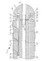
図1において、カテーテル本体部12は単一で中心軸方向の内孔18を有する細長い管状構造体から構成されている。このカテーテル本体部12は柔軟性、すなわち、屈曲可能であるが、その長さ方向に沿ってほとんど非圧縮性である。このカテーテル本体部12は任意の適当な構造体とすることができ、任意の適当な材料で形成できるが、現在好まれている構造体はポリウレタンまたはPEBAXにより形成された外壁部22を有している。この外壁部22はステンレススチール製の埋め込まれた編みメッシュ等から構成されていて、カテーテル本体部12の捩れ剛性を高めており、制御ハンドル16が回転すると、カテーテル10の先端部位14がこれに追随して回転するようになっている。カテーテル本体部12の単一内孔18の中をリード線、注入チューブおよび圧縮コイルが延在しており、さらに、この圧縮コイルの中に引張りワイヤが貫走している。単一内孔型のカテーテル本体部は複数内孔型のカテーテル本体部に比して好ましいが、その理由は、カテーテルの回転時に単一内孔型本体部の方が先端制御性において優れているためである。さらに、単一内孔型においては、リード線、注入チューブおよび圧縮コイルにより囲まれる引張りワイヤがカテーテル本体部内において独立浮遊できる。しかしながら、これらのワイヤ部材が複数個の穴の中で束縛されると、ハンドルの回転時にエネルギーが蓄積されて、ハンドルを開放した場合にカテーテル本体部が回転して戻るようになり、また、湾曲部において屈曲する際にはじける畏れもあり、いずれにしても、その特性において望ましくない結果となる。 In FIG. 1, the
カテーテル本体部12の外径は特に限定する必要はないが、好ましくは、約8フレンチ(french)であり、さらに好ましくは、7フレンチである。同様に、外壁部22の厚さも特に限定しないが、中心内孔18が注入チューブ、引張りワイヤ、リード線および他の任意のワイヤ、ケーブルまたはチューブに適応できる程度に薄いものである。この外壁部22の内面側には剛性賦与チューブ20が配置されており、当該チューブ20はポリイミドまたはナイロンのような任意の適当な材料により形成できる。この剛性賦与チューブ20は編みメッシュの外壁部22と共に改善された捩れ安定性を提供すると共に、カテーテルの外壁厚を最小にする作用効果があり、これによって、中心内孔18の直径を最大にできる。剛性賦与チューブ20の外径は外壁部22の内径とほぼ同じか僅かに小さい。この剛性賦与チューブ20にはポリイミドチューブが現在では好適であり、その理由は、当該ポリイミド材が極めて良好な剛性を与えながら極めて薄い厚さにできるためである。さらに、このことによって、強度および剛性を犠牲にすることなく、中心内孔18の直径を最大にできる。 The outer diameter of the
特に好ましいカテーテルは約0.090インチ乃至約0.94インチの外径と約0.061インチ乃至約0.065インチの内径を有する外壁部22と、約0.060インチ乃至約0.064インチの外径と約0.051インチ乃至約0.056インチの内径を有するポリイミド剛性賦与チューブ20を有している。 A particularly preferred catheter has an
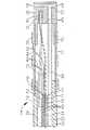
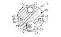
図3および図5に示すように、先端部位14は3個の内孔を有するチューブ19の短い部分から構成されている。このチューブ19は、好ましくは、カテーテル本体部12よりも柔軟な適当な無毒性材料により形成されている。なお、現在では、このチューブ19の好ましい材料として、編み込まれたポリウレタン、すなわち、ステンレススチールの編みメッシュを埋め込んだポリウレタン等が挙げられる。この先端部位14の外径は、カテーテル本体部12と同様に、約8フレンチよりも小さいのが好ましく、さらに好ましくは7フレンチである。なお、各内孔部の大きさは特に限定しない。特に好ましい実施形態においては、先端部位14は約7フレンチ(0.092インチ)の外径を有しており、第1内孔30および第2内孔32は約0.020インチ乃至約0.024インチ、好ましくは0.022インチの直径のほぼ同じ大きさに形成されている。加えて、第3内孔34は約0.032インチ乃至約0.038インチ、好ましくは、0.036インチの僅かに大きな直径を有している。 As shown in FIGS. 3 and 5, the
図2にカテーテル本体部12と先端部位14の好ましい取り付け手段を示している。すなわち、先端部位14の基端部には外周ノッチ部24が設けられていて、このノッチ部にカテーテル本体部12の外壁部22の内側表面が受容される。これらの先端部位14およびカテーテル本体部12は接着剤等の手段により取り付けられる。なお、先端部位14とカテーテル本体部12との取り付けに先だって、剛性賦与チューブ20がカテーテル本体部12内に挿入される。この剛性賦与チューブ20の先端部はポリウレタン接着剤等を用いて接着ジョイント23を形成することによってカテーテル本体部12の先端部近傍に固定して取り付けられる。好ましくは、カテーテル本体部12の先端部と剛性賦与チューブ20の先端部との間に、例えば、約3mm程度の小さな間隔を設けて、先端部位14のノッチ部24を受容するようにする。剛性賦与チューブ20の基端部に力を加えて、当該剛性賦与チューブ20を圧縮しながら、第1接着剤ジョイント(図示せず)を剛性チューブ20と外壁部22との間に、例えば、Super Glue(登録商標)のような高速乾燥接着剤によって形成する。その後、第2接着剤ジョイント26を剛性賦与チューブ20の基端部と外壁部22との間に、例えば、ポリウレタンのようなより遅い乾燥速度でより強力な接着剤を用いて形成する。 FIG. 2 shows a preferable attachment means for the catheter
必要であれば、カテーテル本体部内の剛性賦与チューブ20と先端部位14の基端部との間にスペーサーを配置できる。このスペーサーはカテーテル本体部と先端部位との接合部における柔軟性に遷移性を持たせることができ、これによって、この接合部が折たたみやよじれを生じることなく滑らかに屈曲できる。なお、このようなスペーサーを有するカテーテルは、本明細書に参考文献として含まれる「操作可能な直接心筋脈管再生用カテーテル(Steerable Direct Myocardial Revascularization Catheter)」と題する米国特許出願第08/924,616号に記載されている。 If necessary, a spacer can be disposed between the
さらに、先端部位14の先端部には先端電極36が取り付けられている。好ましくは、この先端電極36はチューブ19の外径とほぼ同じ外径を有している。図3に示すように、この先端電極36は一般に固体であって、流体通路35と一対のめくら穴31およびめくら穴33を備えており、これらの穴は先端部位14における3個の内孔34,30および内孔32の大きさおよび場所にそれぞれ対応している。めくら穴31およびめくら穴33は先端電極36の基端部から延出しているが、当該先端電極の先端部を抜け出ることはない。図示の実施形態においては、流体通路35は軸方向の分岐点と6個の横方向の分岐部48を有しており、これらの分岐部はこの軸方向の分岐点の先端部から先端電極36の外表面に半径方向に延出している。なお、当該流体通路は任意に変形可能である。 Further, a
好ましい先端電極は約3.5mmの有効長、すなわち、その先端部からチューブの先端部19までの長さと、約4.0mmの実際長、すなわち、その先端部からその基端部までの長さを有している。図3に示すように、この好ましい先端電極36は、当該先端電極36の基端部にノッチ部37を形成し、チューブ19の先端部上に当該先端電極の基端部を配置して、このノッチ部37を接着剤で充填することによって、チューブ19に取り付けられる。なお、先端電極36内に延在する各ワイヤやチューブはこの先端電極を先端部位に保持する補助効果を有する。 A preferred tip electrode has an effective length of about 3.5 mm, ie, the length from its tip to the
図示の好ましい実施形態においては、先端電極36の基端側のチューブ19に3個の環状電極38が取り付けられている。なお、この環状電極38の位置および環状電極38の個数は任意に変更可能である。各環状電極38はチューブ19上を摺動して接着剤等によって固定される。 In the illustrated preferred embodiment, three
さらに、先端電極36と環状電極38は任意の適当な材料によって形成でき、好ましくは、プラチナ−イリジウム(90%プラチナ/10%イリジウム)合金棒を加工して形成される。 Further, the
これらの先端電極36および環状電極38はそれぞれ別々のリード線40に接続している。これらのリード線40は先端部位14の第1内孔30内から、カテーテル本体部12の中心内孔18および制御ハンドル16を経て、適当なモニター(図示せず)に接続できる入力ジャック(図示せず)内におけるそれらの基端部まで延出している。さらに、カテーテル本体部12の中心内孔18、制御ハンドル16およびセンタ部位14の基端部に延在する各ワイヤ40の部分は保護シース39内に包容されており、当該保護シースは任意の適当な材料、好ましくは、ポリイミドにより形成されている。この保護シース39はポリウレタン接着剤等を用いて第2内孔32に接着することにより、先端部位14の基端部にその先端部を係留されている。 The
各リード線40は先端電極36および環状電極38に任意の従来技法により取り付けられている。例えば、リード線40の先端電極36への接続は当該リード線40を先端電極36における第2内孔33の中に溶接することにより行なわれる。 Each
また、リード線40の各環状電極38への接続は、好ましくは、チューブ19を貫通する小孔をまず形成することによって行なわれる。さらに、このような小孔は、例えば、チューブ19内に針を挿入した後に、この針を十分に加熱することによって永久穴を形成することにより作成できる。その後、リード線40をマイクロフックのような手段を用いてこの穴に通す。さらに、各リード線40の端部の被覆部を剥がして、環状電極38の下側にはんだ付けまたは溶接する。その後、環状電極38を穴の上に摺動してポリウレタン等によって固定する。 The
温度感知手段が先端電極36に備えられており、必要であれば、環状電極38にも備えられている。この温度感知手段としては、例えば、熱電対やサーミスタのような任意の従来の温度感知手段が使用できる。なお、図3において、先端電極36のための好ましい温度感知手段はワイヤ対により形成される熱電対から構成されている。このワイヤ対の一方は、例えば、40番銅線のような銅線41である。また、ワイヤ対の他方の線は、当該ワイヤ対の支持およびワイヤ対の強度を賦与するコンスタンタン線45である。このワイヤ対の線41および線45は、その先端部でねじり合わせて接触している部分以外は、例えばポリイミド等のプラスチックチューブ43の短片により被覆され、さらに、エポキシによって被覆されて、それぞれ互いに電気的に絶縁されている。プラスチックチューブ43はポリウレタン等によって先端電極36の第1のめくら穴31の中に取り付けられている。線41および線45はこの第1内孔31から先端部位14に延在している。さらに、カテーテル本体部12の中では、線41および線45はリード線40と共に保護シース39の中を貫走している。その後、これらの線41および線45は制御ハンドル16から抜け出て温度モニタ(図示せず)に接続可能なコネクタ(図示せず)に接続している。 Temperature sensing means is provided on the
あるいは、上記温度感知手段はサーミスタであってもよい。なお、本発明において使用する適当なサーミスタは、例えば、Thermometrics社(ニュージャージー州)により販売されるAB6N2−GC14KA143E/37C型である。 Alternatively, the temperature sensing means may be a thermistor. A suitable thermistor used in the present invention is, for example, the AB6N2-GC14KA143E / 37C type sold by Thermometrics (New Jersey).
引張りワイヤ42がカテーテル本体部12を延出してその基端部が制御ハンドルに係留されており、また、その先端部が先端部位14に係留されている。この引張りワイヤ42はステンレススチールまたはNitinol のような任意の適当な材料により形成でき、好ましくは、Teflon(登録商標)等によって被覆されている。この被覆材は引張りワイヤ42に潤滑性を賦与する。好ましくは、引張りワイヤ42は約0.006インチ乃至約0.010インチの直径を有している。 A
圧縮コイル44は引張りワイヤ42を囲むようにカテーテル本体部12の中に配置されている。この圧縮コイル44はカテーテル本体部12の基端部から先端部位14の基端部まで延在している。圧縮コイル44は任意の適当な材料により形成できるが、好ましくは、ステンレススチールにより形成されている。この圧縮コイル44は柔軟性、すなわち、屈曲性を賦与し、かつ、圧縮に耐えられるようにそれ自体できつく巻かれている。圧縮コイル44の内径は引張りワイヤ42の直径よりも僅かに大きいのが好ましい。すなわち、引張りワイヤ42のTeflon(登録商標)被覆によって、ワイヤ42が圧縮コイル44の中を自由に摺動できる。必要であれば、特にリード線40が保護シース39により包容されない場合に、圧縮コイル44の別の面を、例えば、ポリイミドチューブで形成した柔軟で非導電性のシースにより被覆して、圧縮コイル44およびカテーテル本体部12内の他の線の間の接触を防止することができる。 The
圧縮コイル44はその基端部において接着ジョイント50によりカテーテル本体部12における剛性賦与チューブ20の基端部に係留されており、その先端部において接着ジョイント51により先端部位14に係留されている。これらの接着ジョイント50および接着ジョイント51は、好ましくは、ポリウレタン接着剤等により構成されている。この接着剤はカテーテル本体部12の外表面と中心内孔18との間に設けた穴を通して注射器等の手段によって供給できる。このような穴は、例えば、針のような手段によりカテーテル本体部12の外壁部22および剛性賦与チューブ20に穴をあけて、この針を十分に加熱することにより永久穴を形成するような方法によって形成できる。その後、接着剤をこの穴から圧縮コイル44の外表面に送り込んで、その外周に充填することにより、圧縮コイル44の前周にわたって接着ジョイント部を形成する。 The
さらに、引張りワイヤ42は先端部位14の第2内孔32の中に延在する。この引張りワイヤ42はその先端部においてめくら穴33の中の先端電極36に係留されている。引張りワイヤ42を先端電極36内に係留するための好ましい方法としては、金属チューブ46をひだ寄せしながら引張りワイヤ42の先端部に取り付けて当該金属チューブ46を第2のめくら穴33の内側に溶接する方法がある。このように引張りワイヤ42を先端電極36の中に係留することによって、先端電極36が先端部位14から外れる可能性を低減できる。あるいは、引張りワイヤ42を先端部位14の側面に取り付けてもよい。先端部位14の第2内孔32の中において、引張りワイヤ42はプラスチック、好ましくは、Teflon(登録商標)のシース81内に延在しており、このシース81は、先端部位の偏向時に、先端部位14の壁に引張りワイヤ42が食い込まないようにしている。 Further, the
注入チューブがカテーテル本体部12内に備えられて、例えば、生理食塩水のような流体を注入して先端電極36を冷却するように構成されている。この注入チューブはまた薬物を注入したり、組織または流体サンプルを収集する場合にも使用できる。この注入チューブは任意の適当な材料により形成でき、好ましくは、ポリイミドチューブにより形成されている。好ましい注入チューブは、外径が約0.32インチ乃至約0.036インチであり、内径が約0.28インチ乃至約0.032インチである。 An injection tube is provided in the
図2、図3および図4において、第1注入チューブセグメント88がカテーテル本体部12の中心内孔18の中を貫走して、先端部位14の第3内孔34の基端部に到達している。第1注入チューブセグメント88の先端部はポリウレタン接着剤等により第3内孔34の中に係留されている。また、第1注入チューブセグメント88の基端部は制御ハンドル16を貫走してルアハブ90、または、制御ハンドルの基端側の一定の場所に延出している。さらに、第2注入チューブセグメント89が第3内孔34の先端部から先端電極36の流体通路35内に貫走している。この第2注入チューブセグメント89は第3内孔34および流体通路35にポリウレタン接着剤等により係留されている。この第2注入チューブセグメント89は、引張りワイヤ42と同様に、先端電極に付加的な支持を賦与する。而して、使用時には、流体がルアハブ90を介して第1注入チューブセグメント88に注入され、当該第1注入チューブセグメント88を流れ、さらに、第3内孔34および第2注入チューブセグメント89を経て、先端電極36内の流体通路35に到達した後に、当該先端電極における流体通路35の横方向分岐部48から流出する。例えば、上記流体通路35を図4に示すように先端電極36の先端部から延出するような長手方向に沿う穴に形成してもよく、先端電極36を十分な多孔質にして当該先端電極の外表面に流体を通過させ得るようにして、この連通性多孔質材により上記流体通路を形成してもよい。 2, 3, and 4, the first
図6に示すような別の配列構成において、単一内孔のサイドアーム94がカテーテル本体部12の基端部近くにおいて中心内孔18に流体を介して接続している。第1注入チューブセグメント88はカテーテル本体部12の中を経て、サイドアーム94に延出して、ルアハブ90のような部材に到達している。サイドアーム94は、好ましくは、外壁部22と同じ材料により形成されているが、例えば0.055インチのようなより大きな厚さを有しているのが好ましい。サイドアーム94のカテーテル本体部12との接合部において、成形ジョイントを備えて付加的な強度および付加的な支持を賦与することができる。この成形ジョイントは任意の生体許容性材料により形成することができ、好ましくは、ポリウレタンにより作られている。 In another arrangement as shown in FIG. 6, a single
先端部位14を偏向するための引張りワイヤ42のカテーテル本体部12に対する長手方向の動きは制御ハンドル16の適当な操作によって行なえる。図7に示すように、制御ハンドル16の先端部は引張りワイヤ42を操作するためのつまみ制御部56を有するピストン54から構成されている。このピストン54にカテーテル本体部12の基端部がシュリンクスリーブ28によって接続されている。 Longitudinal movement of the
さらに、引張りワイヤ42、リード線40、熱電対線41および熱電対線45、および第1注入チューブセグメント88が上記ピストン54を貫走している。引張りワイヤ42はピストン54の基端側に位置するアンカーピン57に係留されている。制御ハンドル16の中では、リード線40および熱電対線41および熱電対線45が保護シース39の中に配置されている。さらに、ピストン54の中では、第1注入チューブセグメント88が、好ましくは、上記サイドアーム94と同様にポリウレタンにより形成される、別の保護シース91の中に延在している。これらの保護シース39および保護シース91は、好ましくは、ポリウレタン接着剤等により接着剤ジョイント53においてピストン54に係留されて、第1注入チューブセグメント88、リード線40および熱電対線41および熱電対線45の制御ハンドル16内における長手方向の移動を可能にすることにより、これらの部材がピストン54の調節による引張りワイヤ42の操作時に破壊されないようにしている。ピストン54の中では、引張りワイヤ42は、好ましくは、ポリイミドチューブの移送チューブ27内に延在して、当該引張りワイヤの接着剤ジョイント53近傍における長手方向の移動を可能にしている。 Further, the
ピストン54は制御ハンドルの胴部55の中に配置されている。この胴部55は一般に固体でピストン54を収容するためのピストンチャンバーを有している。このピストンチャンバーから基端側に、3個の長手方向の穴58,59および穴60と、アンカーピン57を収容するための横方向の穴が延出している。この第2の長手方向の穴59は横方向の穴に連通している。保護シース91内の第1注入チューブセグメント88は第1の長手方向の穴58を貫走している。また、引張りワイヤ42は第2の長手方向の穴59を貫走して横方向の穴の中でアンカーピン57に係留されている。さらに、保護シース39内の熱電対線41および熱電対線45は第3の長手方向の穴60に延在している。長手方向の穴58、59および穴60の先端部とピストン54の基端部との間に、チャンバー62は付加的な空間部を設けて第1注入チューブセグメント88の望ましくない屈曲を回避している。好ましくは、この空間部は少なくとも0.50インチ、より好ましくは約0.60インチ乃至約0.90インチの長さを有している。 The
本発明の別の好ましい実施形態においては、電磁センサー72が先端部位14の先端部内に配置されている。図8に示すように、この実施形態においては、先端電極36が、好ましくは、ポリエーテルエーテルケトン(PEEK)により形成されるプラスチックハウジング21を介して先端部位14のチューブ19に接続している。この先端電極36の基端部は外周に切り欠き部が形成されてステム70が設けられている。このステム70はプラスチックハウジング21の先端部の内側に嵌合して、ポリウレタン接着剤等によりハウジング21に結合されている。一方、プラスチックハウジング21の基端部はポリウレタン接着剤等により先端部位14のチューブ19の先端部に結合されている。好ましくは、このプラスチックハウジングは約1cm程度の長さである。 In another preferred embodiment of the present invention, the
好ましくは、上記先端電極36は全体で約7mmの長さであり、ステム70は約3.5mm(すなわち、先端電極の全長の半分)の長さを有している。先端電極36の先端部は一般に固体であってめくら穴31と6個の横穴48を有する流体通路33を備えている。なお、図示の実施形態においては、先端電極36のステム70は一般に中空である。 Preferably, the
上述のような第2注入チューブセグメント89が先端電極36の流体通路33の中に延出して係留されている。これらのチューブセグメント88およびチューブセグメント89は、好ましくは、約0.029インチ乃至約0.33インチの外径および約0.025インチ乃至約0.029インチの内径を有している。 A second
引張りワイヤ42は先端電極36のめくら穴31の中に延出して係留されている。さらに、上述のような熱電対線41および熱電対線45は先端電極36の第1内孔31の中に延出してはんだ付けされており、銅線41は先端電極においてリード線40としても作用する。電磁センサー72はプラスチックハウジング21および先端電極36の中空ステム70内に配置されている。このセンサー72はポリウレタン接着剤等により先端電極36およびプラスチックハウジング21内に固定して取り付けられている。 The pulling
さらに、プラスチックハウジング21には3個の環状電極38が取り付けられている。これらの環状電極38の配置および環状電極38の個数は必要に応じて変更できる。各環状電極38はプラスチックハウジング21上を摺動して接着剤等により固定される。あるいは、1個以上の環状電極38を先端部位14の柔軟性チューブ19上に配置することも可能である。 Further, three
リード線が概ね上述のように環状電極38に取り付けられているが、プラスチックハウジング21の長さによって、最も先端側の環状電極38は先端電極36のステム70の上におけるプラスチックハウジング21に取り付けられている。この結果、最も先端側の環状電極38のリード線40は当該先端側環状電極38およびステム70の基端側のプラスチックハウジング21に設けられた穴49から延出する。このリード線40はプラスチックハウジング21の外側に沿って少しの距離だけ延出して最も先端側の環状電極38の下側にはんだ付けされている。なお、ポリウレタン接着剤等がこのリード線40の露出部を被覆して穴49を充填するために使用される。 The lead wire is generally attached to the
電磁センサー72は電磁センサーケーブル74に接続しており、このケーブル74は先端部位14の第3内孔34を通り、カテーテル本体部12の中心内孔18を経て、制御ハンドル16内に延出している。さらに、この電磁センサーケーブル74は制御ハンドル16の基端部から延出してへその緒形コード78を介して回路基板を収容する(図示せず)センサー制御モジュール75に接続している。あるいは、この回路基板は、例えば、本明細書に参考文献として含まれる「操作可能な直接心筋脈管再生用カテーテル」と題する米国特許出願第08/924,616号に記載されるような制御ハンドル16内に収容できる。電磁センサーケーブル74はプラスチック被覆したシース内に収容した多数ワイヤから構成されている。上記センサー制御モジュール75において、電磁センサーケーブル74の各ワイヤは回路基板に接続している。この回路基板は電磁センサー72から受け取った信号を増幅して、当該信号を、図9に示すようなセンサー制御モジュール75の基端部におけるセンサーコネクタ77を介して、コンピュータにより理解可能な形態でコンピュータに送る。なお、このカテーテルは1回だけの使用のために設計されているので、上記回路基板には、カテーテルの使用後24時間程度、この回路基板をシャットダウンするEPROMチップが含まれているのが好ましい。このことによって、カテーテルまたは少なくとも電磁センサーが二度使用されるのを防ぐ。本発明における使用に適する電磁センサーは、例えば、本明細書に参考文献として含まれる米国特許第5,558,091号、同第5,443,489号、同第5,480,422号、同第5,546,951号、同第5,568,809号および同第5,391,199号および国際公開第WO95/02995号に記載されている。好ましい電磁マッピングセンサー72は約6mm乃至約7mmの長さで、約1.3mmの直径を有している。 The
このような電磁センサー72を使用するために、患者は、例えば、磁場を発生するためのコイルを収容するパッドを当該患者の下に配置することにより、発生される磁場の中に配置される。さらに、基準電磁センサーが、例えば、患者の背中にテープ留めされて、患者に対して固定され、第2の電磁センサーを収容するカテーテルが患者の心臓内に進入する。各センサーは3個の小形コイルから構成されており、これらのコイルは磁場内においてその磁場におけるそれらの位置を示す微弱な電気的信号を発生する。次に、固定した基準センサーと心臓内の第2のセンサーの両方から発せられた信号が増幅され、コンピュータに送信されて、当該コンピュータがそれらの信号を解析してモニター上に表示する。この方法によれば、基準センサーに対するカテーテル内のセンサーの正確な位置を確認して視覚的に表示できる。さらに、このセンサーは心臓の筋肉収縮により生じるカテーテルの位置ずれも検出できる。 In order to use such an
この技法を用いて、医者は心室を視覚的にマッピングすることが可能になる。このマッピングは心臓壁に接触するまでカテーテル先端部を心室内に進入させることによって行なわれる。この位置が記録されて保存される。その後、カテーテル先端部を心臓壁に接触する別の位置に移動して、その位置を再び記録して保存する。さらに、心室の三次元画像が完成するまでこの方法を繰り返す。好ましいマッピングシステムには多数個の電極と電磁センサーとから構成されるカテーテルが含まれる。 Using this technique, the doctor can visually map the ventricles. This mapping is performed by moving the catheter tip into the ventricle until it contacts the heart wall. This position is recorded and saved. Thereafter, the catheter tip is moved to another position that contacts the heart wall, and that position is recorded and stored again. Further, this method is repeated until a three-dimensional image of the ventricle is completed. A preferred mapping system includes a catheter composed of multiple electrodes and electromagnetic sensors.
カテーテル本体部12は上述のものとほぼ同じであり、開口した中心内孔18を有している。しかしながら、好ましくは、本実施形態のカテーテル本体部12は剛性賦与チューブ20を備えておらず、これは、磁気センサーケーブル74を備えるために中心内孔18内に付加的な空間部を設ける必要があるためである。好ましくは、当該カテーテル本体部は約8フレンチよりも大きくなく、より好ましくは約7フレンチ乃至約7.5フレンチの外径を有している。 The
また、制御ハンドル16は上述のものとほぼ同様であるが、磁気センサーケーブル74が制御ハンドル16の基端部から延出していて、センサー制御モジュール75に接続している。 The control handle 16 is substantially the same as described above, but a
さらに、本発明に従うカテーテルの別の実施形態は、先端部位の操作能力を高めるために、2個の引張りワイヤを収容する二方向カテーテルから構成されている。すなわち、図10に示すように、この実施形態の先端部位14は4個の内孔を有している。約7フレンチの直径を有する先端部位に対して、第1内孔30および第2内孔32の直径は同じサイズであって、各々が0.018インチであるのが好ましい。また、第3内孔34および第4内孔35の直径も同じサイズであって、各々が0.029インチであるのが好ましい。この先端部位14は先端電極36と環状電極38を担持している。さらに、熱電対のような温度感知手段が上述のように先端電極36に備えられている。環状電極38用のリード線40、並びに、一方が先端電極用のリード線として作用する熱電対線40および熱電対線45が第3内孔34内に延在している。先端部位14は電磁センサー72を収容しており、電磁センサーケーブル74は第3内孔34の中を貫走している。さらに、第1注入チューブセグメント88が制御ハンドル16およびカテーテル本体部12を経て第4内孔35内に延在している。また、第2注入チューブセグメント89が、上述の実施形態と同様の態様で、先端部位14における第4内孔の先端部から先端電極36の中に延出している。 Furthermore, another embodiment of the catheter according to the present invention is comprised of a bi-directional catheter that accommodates two pull wires to enhance the maneuverability of the distal site. That is, as shown in FIG. 10, the
さらに、2個の引張りワイヤ42と周囲の圧縮コイル44は、上述のように、制御ハンドル16からカテーテル本体部12の中心内孔18に延出している。先端部位14の中では、1個の引張りワイヤが第1内孔30の中に延在しており、他の1個の引張りワイヤが第2内孔32の中に延在している。その後、これらの引張りワイヤ42は、好ましくは、第1内孔30および第2内孔32と同軸の先端電極36における穴の中に延出して、上述のように先端電極の穴の中で係留される。さらに、先端部位14の中では、引張りワイヤ42は、プラスチック、好ましくはTeflon(登録商標)のシース81の中にそれぞれ延在して、これら引張りワイヤ42が先端部位の偏向時に当該先端部位14の内壁に食い込まないようにしている。さらに、当該引張りワイヤを収容する先端部位の内孔30および内孔32は(長手軸に垂直な断面における)1/4面内にそれぞれ配置することができるが、好ましくは、図10に示すように、対向する1/4面内に配置されている。必要であれば、これらの引張りワイヤの一方または両方の先端部を、例えば、本明細書に参考文献として含まれる米国特許出願第08/924,611号に記載されるように、カテーテル先端部位の側壁部に係留してもよい。さらに、第1の引張りワイヤを第2の引張りワイヤの係留位置の基端側に係留してもよい。 In addition, the two
制御ハンドル構造を含む多数引張りワイヤから構成される特に好ましいカテーテル構造が本明細書に参考文献として含まれる「全方向操作可能カテーテル(Omni-Directional Steerable Catheter)」と題する米国特許出願第08/924,611号に記載されている。すなわち、この出願は2個以上の引張りワイヤを操作するのに適する制御ハンドルを教示している。この教示の制御ハンドルは、電極リード線、電磁センサーケーブル、光ファイバーおよび注入チューブにまで適応するように拡張できる中心通路を備えている。さらに、ハンドルの拡張部は、例えば、図9に示すのと同様の態様で電磁センサー用の回路基板を収容するように構成されている。 A particularly preferred catheter structure composed of multiple puller wires including a control handle structure is incorporated herein by reference, US patent application Ser. No. 08/924, entitled “Omni-Directional Steerable Catheter”. No. 611. That is, this application teaches a control handle suitable for manipulating two or more pull wires. The control handle of this teaching includes a central passage that can be extended to accommodate electrode leads, electromagnetic sensor cables, optical fibers, and injection tubes. Furthermore, the extended portion of the handle is configured to accommodate a circuit board for an electromagnetic sensor, for example, in the same manner as shown in FIG.
図11に本発明の二方向カテーテルの実施形態に特に適する別の制御ハンドル16を示す。この制御ハンドル16は、先端部にノーズピース104を有する概ね固体でほぼ円筒形のハウジング102から構成されている。このハウジング102およびノーズピース104は任意の適当な材料、好ましくはアセタールにより形成できる。カテーテル本体部12はノーズピース104に上述のようにシュリンクスリーブを介して固定して取り付けられている。 FIG. 11 shows another control handle 16 that is particularly suitable for the bi-directional catheter embodiment of the present invention. The control handle 16 comprises a generally solid, substantially
ハウジング102の中には、2個のラックギアチャンネル105が備えられている。好ましくは、ラックギアチャンネル105はハウジング102の中の対向する(長手軸に垂直な断面における)1/4面内に配置されている。さらに、ラックギア106が各ラックギアチャンネル105の中に摺動可能に取り付けられている。各ラックギア106は概ね長方形であって、その内側端面の長さ方向に沿って歯108を有している。ラックギア106の間には歯112を有する平歯車110が備えられている。この平歯車110のは112はラックギア106の歯108とそれぞれ歯合して、一方のラックギアが基端側に移動すると、他方のラックギアが先端側に移動するようになっている。 In the
各引張りワイヤ42の基端部は引張りワイヤ連結部材114により一方のラックギア106の先端部に取り付けられている。連結部材114はラックギア106に一体またはこれに固定して取り付けられている。各ラックギア106は連結部材114にはんだ付けまたは、例えば、ポリウレタンまたはエポキシ接着剤により接着されている。あるいは、各引張りワイヤ連結部材114の基端部が対応するラックギア106の先端部における雄ネジ部に係合するネジ穴により構成されていてもよい。この連結部材114は任意の適当な材料により形成できるが、好ましくはアルミニウムにより形成されている。 The base end portion of each
図12に示すように、各連結部材114の先端部は設定ネジ116を収容する軸方向のネジ穴115を含む。この設定ネジ116はこれを貫通する軸方向のボア118を有しており、このボア内に引張りワイヤ42の基端部が通る。好ましい実施形態においては、この軸方向ボア118は引張りワイヤ42の直径よりも僅かに大きな直径を有する先端部位と当該先端部位の直径よりも大きな直径を有する基端部位を有している。さらに、この軸方向ボア118は設定ネジ116の基端部を貫通している。 As shown in FIG. 12, the distal end portion of each connecting
引張りワイヤ42は設定ネジ116の軸方向ボア118を貫通してこれに係留されている。この引張りワイヤ42を設定ネジ116に係留するための好ましい手段はヒポデミック・ストック120の短片から構成されており、当該短片部材は設定ネジ116の軸方向ボア118の先端部位を通した後に引張りワイヤ42の基端部に、例えば、クリンプ加工によって固定して取り付けられる。このヒポデミック・ストック120は軸方向ボア118の先端部位の直径よりも大きな直径を有しており、引張りワイヤ42が設定ネジ116から抜け出ることを防ぐ。あるいは、例えば、ステンレススチールリボンのような十字部材を引張りワイヤ42の基端部に溶接して、この十字部材により、引張りワイヤが設定ネジ116の軸方向ボア118から抜け出るのを防ぐようにしてもよい。なお、引張りワイヤの基端部を連結部材114に取り付けるための機構は任意のものを使用できる。 The
さらに、連結部材114の中に軸方向の穴119が設けられており、この穴は設定ネジ116内の軸方向ボア118の先端部と同じ直径を有している。軸方向の穴119の先端部は軸方向ボア118の基端部に連通して、対応するラックギア106および連結部材114が先端側に移動する時に、引張りワイヤ42がその中に延出できる通路を形成している。これによって、引張りワイヤ42のゆがみが防止できる。 Further, an
ハンドルハウジング102はラックギア106の一方の位置に対応する一方の側面に沿ってスロット122を備えている。設定ネジ124がスロット122からラックギア106および引張りワイヤ連結部材114内に延出している。さらに、偏向ノブ126が制御ハンドル16の操作を容易にするために設定ネジ124の外側に配置されている。この偏向ノブ126はハンドルハウジング02の外周を囲っていて、ハンドルの回転に関係なく、ノブ126が操作できるようになっている。好ましくは、設定ネジ124はラックギア106上にあって、両方のラックギア106がニュートラル位置、すなわち、互いに同一線上に並んでいる時に、偏向ノブ126はスロット122のほぼ中央に位置している。 The
その後、偏向ノブ126が基端側に移動すると、対応するラックギア106が基端側に移動する。さらに、これに取り付けられた引張りワイヤ42も基端側に移動して、この引張りワイヤが延在している先端部位14の内孔の1/4面の方向に先端部位14が偏向する。逆に、偏向ノブ126を先端側に押出すと、対応するラックギア106が先端側に移動する。この結果、反対側のラックギア106が基端側に移動して、対応する引張りワイヤ42を同方向に移動して、先端部位14を反対方向に偏向する。 Thereafter, when the deflection knob 126 moves to the proximal end side, the
さらに、ハンドルハウジング102の内部には、注入チューブ88、リード線40、熱電対線41および熱電対線45およびセンサーケーブル74が備えられて、当該ハウジング102を貫通してその先端部から延出している。さらに、これらの注入チューブ88、リード線40、熱電対線41および熱電対線45およびセンサーケーブル74はハンドルハウジング102の基端部から出て、上述のように、ルアハブまたは適当なモニターに取り付けられている。 Further, the
図13(A)および図14(A)に別の二方向ハンドル構成を示す。図13(A)、図13(B)、図13(C)および図13(D)に示すように、制御ハンドル16は概ね管状のハンドルハウジング102から構成されており、当該ハウジング102は任意の適当な剛体材料により形成できる。このハウジング102は3個のピストンチャンバー、すなわち、軸方向先端側ピストンチャンバー131および2個のより小さい基端側ピストンチャンバー135から構成されている。基端側ピストンチャンバー135は、好ましくは、ハウジング102の(軸に垂直な断面における)対向する1/4面内にそれぞれあって、先端側ピストンチャンバー131と重なっている。先端部につまみ部材132を有する摺動可能先端側ピストン130および軸方向通路133が先端側ピストンチャンバー131内に取り付けられてハウジング102の先端部から延出している。カテーテル本体部12の基端部は先端側ピストン130に例えば接着剤等により取り付けられている。さらに、引張りワイヤ42、リード線40、熱電対線41および熱電対線45、および第1注入チューブ88を収容する保護シース39が先端側ピストン130の軸方向通路133内に延在している。この先端側ピストン130の基端側には、2個の摺動可能基端側ピストン134が基端側ピストンチャンバー135内にそれぞれ配置されている。これらの基端側ピストン134は任意の適当な材料により形成できるが、アルミニウムが現在では好ましい材料である。各引張りワイヤ42はその基端部において各基端側ピストン134の先端部に係留されている。これらの引張りワイヤ42は、例えば、上述のような連結手段等の、任意の適当な手段によって基端側ピストン134に固定して取り付けられている。 13A and 14A show another two-way handle configuration. As shown in FIGS. 13 (A), 13 (B), 13 (C), and 13 (D), the control handle 16 is composed of a generally
このような配列構成において、上記つまみ部材132を押圧して先端側ピストン130をハンドルハウジング102に対して先端側に移動すると、カテーテル本体部12、引張りワイヤ42および当該引張りワイヤが取り付けられている基端側ピストン134が先端側に移動する。しかしながら、両方の引張りワイヤが同時に移動する時は偏向は起こらない。従って、これらの引張りワイヤの同時移動を阻止するための手段が備えられている。 In such an arrangement, when the
すなわち、上記引張りワイヤ42の同時移動を阻止するための手段は、基端側ピストン134の一方のみの移動を係止または阻止するための手段から構成されている。さらに、この手段は、各基端側ピストン134の長さ方向に沿う外周ノッチ部140と当該基端側ピストン134の選択された一方の外周ノッチ部140に係合する手段との組み合わせによって構成される。 That is, the means for preventing the simultaneous movement of the pulling
上記の好ましい係合手段は可動棒材142から構成されており、この棒材142はハンドルハウジング102を直径方向に貫通して当該ハウジングの各側面から僅かに延出することにより、図13(A)および図13(B)に示すような基端側ピストン134の外周ノッチ部104に対応する位置においてハウジング102の各側面にボタンを形成している。さらに、図14(A)および図14(B)に示すように、棒材142は卵形スロット部146を備えている。このスロット部146には両方の基端側ピストン134が貫通している。このスロット146は基端側ピストン134の直径よりも僅かに大きな幅を有している。さらに、棒材142の横の長さは外周ノッチ部140の長さよりも短いために、棒材142は各ノッチ部140内に収容されてこれに係合できる。スロット146の長さは一度に1個のみのピストンを横方向に移動することを可能にするように選択される。すなわち、図14(A)は、一方の基端側ピストン134の外周ノッチ部140とスロット146の端部が係合するまで棒材142が第1の方向に移動した状態を示している。この構成において、係合状態にある基端側ピストンは棒材142によって長さ方向の移動を阻止されるが、係合状態にない他方の基端側ピストンはスロット部146内を自由に移動できる。さらに、棒材142を別の方向に移動すると、前に係合状態にあった基端側ピストンが長さ方向に自由に動けるようになり、前に自由に移動していた基端側ピストンが係合状態になる。 The preferable engaging means is composed of a
基端側ピストン134が棒材142に係合している時、これに取り付けた引張りワイヤ42の固定した係留部材として作用する。それゆえ、つまみ部材132を押圧して先端側ピストン130をハウジング102に対して先端側に移動すると、カテーテル本体部12が係留されている引張りワイヤ42に対して先端側に移動する。これによって、その引張りワイヤを担持する先端内孔部の方向に先端部位14が偏向する。また、反対側の基端側ピストンが係合されると、反対方向に先端部位14が偏向する。 When the
以上、本発明を現在において好ましいと思われる実施形態に基づいて説明したが、当該技術分野における熟達者であれば、本発明の原理、趣旨および範囲を逸脱することなく本明細書に記載される構造および構成の変更または変形を行なうことが可能である。 Although the present invention has been described based on the presently preferred embodiments, those skilled in the art will be able to describe it herein without departing from the principles, spirit and scope of the invention. Changes or modifications in structure and configuration are possible.
従って、上述ならびに上記図面に基づく構造および構成は例示的なものであって、本発明の範囲を限定するものではなく、当該範囲は本明細書に記載される特許請求の範囲のみによって限定されるものと解するべきである。 Accordingly, the structures and configurations described above and based on the drawings are exemplary and do not limit the scope of the invention, which is limited only by the claims set forth herein. It should be understood as a thing.
本発明の具体的な実施態様は以下の通りである。
(A)外壁部と、基端部および先端部と、これらを貫通する単一の中心内孔を有するカテーテル本体部と、
前記カテーテル本体部の基端部に配置される制御ハンドルと、
基端部および先端部と、これらを貫通する少なくとも1個の内孔を有する柔軟性チューブのセグメントから成る先端部位とから成り、当該先端部位の基端部が前記カテーテル本体部の先端部に固定して取り付けられており、さらに、
前記先端部位のチューブの先端部に固定して取り付けられた先端電極から成り、当該先端電極が前記先端部位の内孔と流体を介して連通する少なくとも1個の流体通路を有しており、さらに、
基端部および先端部を有する注入チューブから成り、当該注入チューブが前記カテーテル本体部における中心内孔の中を貫走しており、当該注入チューブの先端部が前記先端電極の流体通路の基端部と流体を介して連通することによって、流体が注入チューブから、先端電極の流体通路を介して、当該先端電極の外表面に流れることができ、さらに、
前記制御ハンドルを操作することにより前記先端部位を偏向するための手段から成ることを特徴とする灌注可能な先端部を有する操作可能なカテーテル。
(1)前記流体通路が前記先端部位を貫通して当該先端部位の外表面に至る少なくとも1個の長手方向の通路から成る実施態様(A)に記載のカテーテル。
(2)前記流体通路が少なくとも1個の横方向の通路から成る実施態様(A)に記載のカテーテル。
(3)前記流体通路が少なくとも1個の長手方向の通路と少なくとも1個の横方向の通路との組み合わせから成る実施態様(A)に記載のカテーテル。
(4)前記先端電極が多孔質であって、前記流体通路が当該先端電極の多孔質性による内部連通によって形成されている実施態様(A)に記載のカテーテル。
(5)前記注入チューブの先端部が前記先端部位における内孔に延出して液体を介して連通し、さらに、前記先端電極における流体通路に流体を介して連通しており、これによって、流体が注入チューブから、先端部位の内孔および流体通路を介して、先端電極の外表面に流れる実施態様(A)に記載のカテーテル。Specific embodiments of the present invention are as follows.
(A) an outer wall portion, a proximal end portion and a distal end portion, and a catheter body portion having a single central inner hole penetrating them,
A control handle disposed at the proximal end of the catheter body,
It consists of a proximal end portion and a distal end portion, and a distal end portion composed of a segment of a flexible tube having at least one inner hole penetrating them, and the proximal end portion of the distal end portion is fixed to the distal end portion of the catheter main body portion Attached, and
A tip electrode fixedly attached to the tip of the tube at the tip portion, the tip electrode having at least one fluid passage communicating with the inner hole of the tip portion via a fluid; ,
An injection tube having a proximal end and a distal end, the injection tube extending through a central inner hole in the catheter body, and the distal end of the injection tube is a proximal end of the fluid passage of the distal electrode By communicating with the part via the fluid, the fluid can flow from the injection tube to the outer surface of the tip electrode via the fluid passage of the tip electrode,
A manipulable catheter having an irrigable tip comprising means for deflecting the tip portion by manipulating the control handle.
(1) The catheter according to the embodiment (A), wherein the fluid passage includes at least one longitudinal passage extending through the distal end portion and reaching an outer surface of the distal end portion.
(2) The catheter according to embodiment (A), wherein the fluid passage comprises at least one lateral passage.
(3) The catheter according to embodiment (A), wherein the fluid passage comprises a combination of at least one longitudinal passage and at least one transverse passage.
(4) The catheter according to the embodiment (A), in which the tip electrode is porous and the fluid passage is formed by internal communication due to the porous nature of the tip electrode.
(5) The distal end portion of the injection tube extends through an inner hole in the distal end portion and communicates via a liquid, and further communicates via a fluid to a fluid passage in the distal end electrode. The catheter according to embodiment (A), which flows from the injection tube to the outer surface of the tip electrode via the inner hole and fluid passage of the tip portion.
(6)前記注入チューブが2個の分離したセグメントから構成されており、
第1の注入チューブセグメントが基端部および先端部を有しており、当該先端部が前記先端部位の内孔に流体を介して連通し、さらに、前記先端電極における流体通路に流体を介して連通しており、
第2の注入チューブセグメントが、前記第1の注入チューブセグメントが延出している前記先端部位の内孔の先端部から前記先端電極における流体通路内に延出しており、これによって、流体が第1注入チューブセグメントから、先端部位の内孔、第2注入チューブセグメントおよび流体通路を介して、先端電極の外表面に流れる実施態様(A)に記載のカテーテル。
(7)前記注入チューブが前記先端部位の内孔の中を貫走して前記先端電極における流体通路の先端部において係留されている実施態様(A)に記載のカテーテル。
(8)前記注入チューブの基端部がルアハブ内に収容されている実施態様(A)に記載のカテーテル。
(9)前記注入チューブの基端部が前記制御ハンドルの基端部から延出している実施態様(A)に記載のカテーテル。
(10)前記注入チューブの基端部が前記カテーテル本体部の側面から延出している実施態様(A)に記載のカテーテル。(6) the injection tube is composed of two separate segments;
The first injection tube segment has a proximal end portion and a distal end portion, and the distal end portion communicates with an inner hole of the distal end portion via a fluid, and further, a fluid passes through a fluid passage in the distal end electrode. Communicated,
The second injection tube segment extends from the tip of the inner hole of the tip portion from which the first injection tube segment extends into the fluid passage in the tip electrode, thereby allowing fluid to flow through the first injection tube segment. The catheter according to embodiment (A), which flows from the infusion tube segment to the outer surface of the distal electrode through the inner hole at the distal end portion, the second infusion tube segment and the fluid passage.
(7) The catheter according to the embodiment (A), in which the injection tube penetrates through an inner hole of the distal end portion and is anchored at a distal end portion of a fluid passage in the distal end electrode.
(8) The catheter according to the embodiment (A), in which a proximal end portion of the infusion tube is accommodated in a luer hub.
(9) The catheter according to the embodiment (A), wherein a proximal end portion of the infusion tube extends from a proximal end portion of the control handle.
(10) The catheter according to the embodiment (A), wherein a proximal end portion of the infusion tube extends from a side surface of the catheter main body.
(11)前記先端部位がこれを貫通する3個の内孔を有している実施態様(A)に記載のカテーテル。
(12)前記制御ハンドルが前記カテーテル本体部の基端部に固定して取り付けられている第1の部材と、当該第1の部材に対して移動可能な第2の部材とから成る実施態様(A)に記載のカテーテル。
(13)前記偏向手段が基端部および先端部を有する引張りワイヤを備えており、当該引張りワイヤが前記制御ハンドルから前記カテーテル本体部を介して前記先端部位の内孔に延在しており、前記引張りワイヤの先端部が前記先端部位内に固定されており、前記引っ張りワイヤの基端部が前記制御ハンドルの第2部材に固定されており、これによって、制御ハンドルの第1部材を制御ハンドルの第2部材に対して操作することにより、引張りワイヤをカテーテル本体部に対して移動して先端部位を偏向する実施態様(12)に記載のカテーテル。
(14)前記偏向手段がさらに前記引張りワイヤを囲むように前記カテーテル本体部内に延在する圧縮コイルから成る実施態様(13)に記載のカテーテル。
(15)さらに、温度感知手段から成る実施態様(A)に記載のカテーテル。(11) The catheter according to the embodiment (A), in which the distal end portion has three inner holes penetrating therethrough.
(12) An embodiment in which the control handle includes a first member fixedly attached to a proximal end portion of the catheter body, and a second member movable with respect to the first member. The catheter according to A).
(13) The deflection means includes a pulling wire having a proximal end portion and a distal end portion, and the pulling wire extends from the control handle to the inner hole of the distal end portion through the catheter body portion, A distal end portion of the pulling wire is fixed in the distal end portion, and a proximal end portion of the pulling wire is fixed to the second member of the control handle, whereby the first member of the control handle is connected to the control handle. The catheter according to the embodiment (12), wherein the distal member is deflected by moving the pulling wire relative to the catheter main body by operating the second member.
(14) The catheter according to embodiment (13), wherein the deflecting means further comprises a compression coil extending into the catheter main body so as to surround the pulling wire.
(15) The catheter according to embodiment (A), further comprising temperature sensing means.
(16)前記温度感知手段が銅線およびコンスタンタン線から成るエナメル線対により形成されている熱電対から成り、当該線対がカテーテル本体部の内孔から、前記先端部位の内孔を介して、前記先端電極におけるめくら穴の中に固定して取り付けられている実施態様(15)に記載のカテーテル。
(17)さらに、電磁マッピングセンサーの位置を示す電気的信号を発生するために先端部位の先端部に配置された電磁センサーと、当該電磁センサーを画像処理システムに接続するための手段とから成る実施態様(A)に記載のカテーテル。
(18)前記電磁センサーを画像処理システムに接続するための手段が当該電磁マッピングセンサーに電気的に取り付けられて、前記先端部位の内孔から前記カテーテル本体部の内孔を経て前記制御ハンドルに延出するセンサーケーブルから成る実施態様(17)に記載のカテーテル。
(19)さらに、先端部および基端部を有する管状ハウジングから成り、当該管状ハウジングの先端部が前記先端電極の基端部に固定して取り付けられており、当該管状ハウジングの基端部が前記先端部位の柔軟性チューブの先端部に固定して取り付けられており、これによって、少なくとも前記電磁センサーの一部分が前記管状ハウジング内に収容されている実施態様(17)に記載のカテーテル。
(20)前記カテーテル本体部の外壁部がポリウレタンまたはPEBAXから成る実施態様(A)に記載のカテーテル。(16) The temperature sensing means is composed of a thermocouple formed by an enameled wire pair made of a copper wire and a constantan wire, and the wire pair passes from the inner hole of the catheter main body portion through the inner hole of the distal end portion. The catheter according to embodiment (15), wherein the catheter is fixedly mounted in a blind hole in the tip electrode.
(17) An implementation further comprising: an electromagnetic sensor disposed at the distal end of the distal site to generate an electrical signal indicating the position of the electromagnetic mapping sensor; and means for connecting the electromagnetic sensor to the image processing system The catheter according to aspect (A).
(18) A means for connecting the electromagnetic sensor to the image processing system is electrically attached to the electromagnetic mapping sensor and extends from the inner hole of the distal end portion to the control handle through the inner hole of the catheter body. The catheter according to embodiment (17), comprising an outgoing sensor cable.
(19) Further, the tubular housing has a distal end portion and a proximal end portion, and the distal end portion of the tubular housing is fixedly attached to the proximal end portion of the distal end electrode, and the proximal end portion of the tubular housing is The catheter according to embodiment (17), wherein the catheter is fixedly attached to the distal end portion of the flexible tube at the distal end portion, whereby at least a part of the electromagnetic sensor is accommodated in the tubular housing.
(20) The catheter according to embodiment (A), wherein the outer wall of the catheter body is made of polyurethane or PEBAX.
(21)前記カテーテル本体部の外壁部が埋め込まれたステンレススチール編みメッシュから成る実施態様(A)に記載のカテーテル。
(22)前記カテーテル本体部がさらに前記外壁部の内側に張られる内側剛性賦与チューブから成る実施態様(A)に記載のカテーテル。
(23)前記剛性賦与チューブがポリイミドから成る実施態様(22)に記載のカテーテル。
(24)前記先端部位の柔軟性チューブがポリウレタンにより形成されている実施態様(A)に記載のカテーテル。
(B)外壁部と、基端部および先端部と、これらを貫通する単一の中心内孔を有するカテーテル本体部と、
前記カテーテル本体部の基端部に配置される制御ハンドルと、
基端部および先端部と、これらを貫通する少なくとも1個の内孔を有する柔軟性チューブから成る先端部位とから成り、当該先端部位の基端部が前記カテーテル本体部の先端部に固定して取り付けられており、さらに、
前記先端部位の柔軟性チューブの先端部に固定して取り付けられた先端電極から成り、当該先端電極が前記先端部位の内孔と流体を介して連通する少なくとも1個の流体通路を有しており、さらに、
基端部および先端部を有する注入チューブから成り、当該注入チューブが前記カテーテル本体部における中心内孔の中を貫走しており、当該注入チューブの先端部が前記先端電極の流体通路の基端部と流体を介して連通することによって、流体が注入チューブから、先端電極の流体通路を介して、当該先端電極の外表面に流れることができ、さらに、
基端部および先端部を有する電磁センサーから成り、当該センサーが前記先端部位内に配置されており、さらに、
前記電磁センサーを画像処理システムに接続するための手段と、
前記制御ハンドルを操作することにより前記先端部位を偏向するための手段とから成ることを特徴とする灌注可能な先端部を有する操作可能なカテーテル。
(25)前記流体通路が前記先端部位を貫通して当該先端部位の外表面に至る少なくとも1個の長手方向の通路から成る実施態様(B)に記載のカテーテル。(21) The catheter according to embodiment (A), which is made of a stainless steel knitted mesh in which an outer wall portion of the catheter main body is embedded.
(22) The catheter according to embodiment (A), wherein the catheter main body further includes an inner rigidity imparting tube that is stretched inside the outer wall.
(23) The catheter according to embodiment (22), wherein the rigidity-imparting tube is made of polyimide.
(24) The catheter according to the embodiment (A), wherein the flexible tube at the distal end portion is made of polyurethane.
(B) an outer wall portion, a proximal end portion and a distal end portion, and a catheter body portion having a single central inner hole penetrating them,
A control handle disposed at the proximal end of the catheter body,
A proximal end portion and a distal end portion, and a distal end portion composed of a flexible tube having at least one inner hole penetrating the proximal end portion, and the proximal end portion of the distal end portion is fixed to the distal end portion of the catheter main body portion. Attached, and
It consists of a tip electrode fixedly attached to the tip of the flexible tube at the tip portion, and the tip electrode has at least one fluid passage communicating with the inner hole of the tip portion via a fluid. ,further,
An injection tube having a proximal end and a distal end, the injection tube extending through a central inner hole in the catheter body, and the distal end of the injection tube is a proximal end of the fluid passage of the distal electrode By communicating with the part via the fluid, the fluid can flow from the injection tube to the outer surface of the tip electrode via the fluid passage of the tip electrode,
Consisting of an electromagnetic sensor having a proximal end and a distal end, wherein the sensor is disposed within the distal end portion;
Means for connecting the electromagnetic sensor to an image processing system;
An operable catheter having an irrigable tip, comprising means for deflecting the tip portion by operating the control handle.
(25) The catheter according to embodiment (B), wherein the fluid passage includes at least one longitudinal passage that penetrates the distal end portion and reaches an outer surface of the distal end portion.
(26)前記流体通路が少なくとも1個の横方向の通路から成る実施態様(B)に記載のカテーテル。
(27)前記流体通路が少なくとも1個の長手方向の通路と少なくとも1個の横方向の通路との組み合わせから成る実施態様(B)に記載のカテーテル。
(28)前記電磁センサーを画像処理システムに接続するための手段が当該電磁センサーに接続されたセンサーケーブルから成り、当該センサーケーブルが前記先端部位から、前記カテーテル本体部の中心内孔を介して、前記制御ハンドル内に延出している実施態様(B)に記載のカテーテル。
(29)前記電磁センサーの先端部が前記先端電極におけるめくら穴の中に配置されている実施態様(B)に記載のカテーテル。
(30)さらに、先端部および基端部を有する管状ハウジングから成り、当該管状ハウジングの先端部が前記先端電極の基端部に固定して取り付けられており、当該管状ハウジングの基端部が前記先端部位の柔軟性チューブの先端部に固定して取り付けられており、これによって、少なくとも前記電磁センサーの一部分が前記管状ハウジング内に収容されている実施態様(B)に記載のカテーテル。(26) The catheter according to embodiment (B), wherein the fluid passage comprises at least one lateral passage.
(27) The catheter of embodiment (B), wherein the fluid passage comprises a combination of at least one longitudinal passage and at least one transverse passage.
(28) The means for connecting the electromagnetic sensor to the image processing system comprises a sensor cable connected to the electromagnetic sensor, and the sensor cable extends from the distal end portion through a central inner hole of the catheter main body, The catheter of embodiment (B), extending into the control handle.
(29) The catheter according to the embodiment (B), in which a tip portion of the electromagnetic sensor is disposed in a blind hole in the tip electrode.
(30) Further, it comprises a tubular housing having a distal end portion and a proximal end portion, and the distal end portion of the tubular housing is fixedly attached to the proximal end portion of the distal end electrode, and the proximal end portion of the tubular housing is The catheter according to embodiment (B), wherein the catheter is fixedly attached to the distal end portion of the flexible tube at the distal end portion, whereby at least a part of the electromagnetic sensor is accommodated in the tubular housing.
(31)前記管状ハウジングがPEEKにより形成されている実施態様(30)に記載のカテーテル。
(32)前記カテーテル本体部が約7.5フレンチの直径を有している実施態様(B)に記載のカテーテル。
(C)外壁部と、基端部および先端部と、これらを貫通する単一の中心内孔を有するカテーテル本体部と、
前記カテーテル本体部の基端部に配置される制御ハンドルとから成り、当該制御ハンドルが前記カテーテル本体部の基端部に固定して取り付けられた第1の部材と、当該第1の部材に対して移動可能な少なくとも2個の第2の部材を備えており、さらに、
基端部および先端部と、これらを貫通する少なくとも1個の内孔を有する柔軟性チューブから成る先端部位から成り、当該先端部位の基端部が前記カテーテル本体部の先端部に固定して取り付けられており、さらに、
前記先端部位の先端部に固定して取り付けられた先端電極から成り、当該先端電極が前記先端部位の内孔と流体を介して連通する少なくとも1個の流体通路を有しており、さらに、
基端部および先端部を有する注入チューブから成り、当該注入チューブが前記カテーテル本体部における中心内孔の中を貫走しており、当該注入チューブの先端部が前記先端電極の流体通路の基端部と流体を介して連通することによって、流体が注入チューブから、先端電極の流体通路を介して、当該先端電極の外表面に流れることができ、さらに、
基端部および先端部を有する少なくとも2個の引張りワイヤから成り、各引張りワイヤの基端部が前記制御ハンドル内の1個の分離した第2の部材に係留されており、各引張りワイヤの先端部が前記先端部位内の1個の分離した係留位置に係留されており、
これによって、前記第1の部材に対して選択された第2の部材を移動することにより、当該選択された第2の部材に係留される引張りワイヤの前記先端部位内の係留位置の方向に前記先端部位を偏向することができることを特徴とする灌注可能な先端部を有する多数方向に操作可能なカテーテル。
(33)前記流体通路が前記先端電極から当該先端電極の外表面に延出する少なくとも1個の長手方向の通路から成る実施態様(C)に記載のカテーテル。
(34)前記流体通路が前記先端電極から当該先端電極の外表面に延出する少なくとも1個の横方向の通路から成る実施態様(C)に記載のカテーテル。
(35)前記流体通路が少なくとも1個の長手方向の通路と少なくとも1個の横方向の通路との組み合わせから成る実施態様(C)に記載のカテーテル。(31) The catheter according to embodiment (30), wherein the tubular housing is formed of PEEK.
(32) The catheter according to embodiment (B), wherein the catheter body has a diameter of about 7.5 French.
(C) an outer wall portion, a proximal end portion and a distal end portion, and a catheter body portion having a single central inner hole penetrating them,
A control handle disposed at the proximal end of the catheter body, the control handle being fixedly attached to the proximal end of the catheter body, and the first member And at least two second members that are movable,
It consists of a distal end portion consisting of a proximal end portion and a distal end portion and a flexible tube having at least one inner hole penetrating them, and the proximal end portion of the distal end portion is fixed and attached to the distal end portion of the catheter body portion In addition,
It consists of a tip electrode fixedly attached to the tip of the tip portion, and the tip electrode has at least one fluid passage communicating with the inner hole of the tip portion via a fluid,
An injection tube having a proximal end and a distal end, the injection tube extending through a central inner hole in the catheter body, and the distal end of the injection tube is a proximal end of the fluid passage of the distal electrode By communicating with the part via the fluid, the fluid can flow from the injection tube to the outer surface of the tip electrode via the fluid passage of the tip electrode,
And comprising at least two tension wires having a proximal end and a distal end, the proximal end of each tension wire being anchored to a separate second member in the control handle, the distal end of each tension wire The part is moored at one separate mooring position in the tip region,
Accordingly, by moving the selected second member with respect to the first member, the direction of the pulling wire to be anchored to the selected second member in the direction of the anchoring position in the distal end portion of the pulling wire A multi-directionally operable catheter having an irrigable tip, characterized in that the tip portion can be deflected.
(33) The catheter according to embodiment (C), wherein the fluid passage includes at least one longitudinal passage extending from the tip electrode to an outer surface of the tip electrode.
(34) The catheter according to embodiment (C), wherein the fluid passage includes at least one lateral passage extending from the tip electrode to an outer surface of the tip electrode.
(35) The catheter of embodiment (C), wherein the fluid passage comprises a combination of at least one longitudinal passage and at least one transverse passage.
(36)さらに、2個の引張りワイヤから成る実施態様(C)に記載のカテーテル。
(37)前記引張りワイヤが前記先端電極における別々の場所に係留されている実施態様(C)に記載のカテーテル。
(38)前記引張りワイヤが前記先端部位において対向する1/4面内に係留されている実施態様(C)に記載のカテーテル。
(39)前記引張りワイヤが前記柔軟性チューブの長さ方向に沿う少なくとも2個の異なる選択された場所において前記先端部位内に係留されている実施態様(C)に記載のカテーテル。
(40)さらに、前記カテーテル本体部において、各引張りワイヤを囲むように配置された圧縮コイルから成る実施態様(C)に記載のカテーテル。(36) The catheter according to embodiment (C), further comprising two pull wires.
(37) The catheter according to embodiment (C), wherein the pulling wires are anchored at different locations in the tip electrode.
(38) The catheter according to the embodiment (C), in which the pulling wire is anchored in a ¼ plane facing each other at the distal end portion.
(39) The catheter according to embodiment (C), wherein the puller wire is anchored in the tip portion at at least two different selected locations along the length of the flexible tube.
(40) The catheter according to embodiment (C), further comprising a compression coil arranged so as to surround each pull wire in the catheter main body.
12 カテーテル本体部
14 先端部位
16 制御ハンドル
36 先端電極
42 偏向手段(引張りワイヤ)
88 注入チューブ(第1セグメント)
89 注入チューブ(第2セグメント)DESCRIPTION OF
88 Injection tube (first segment)
89 Injection tube (second segment)
Claims (2)
Translated fromJapanese外壁部と、基端部および先端部と、これらを貫通する少なくとも一つの中心内孔を有するカテーテル本体部と、
前記カテーテル本体部の基端部に配置される制御ハンドルと、
基端部および先端部と、これらを貫通する少なくとも1個の内孔を有する柔軟性チューブを有する先端部位であって、当該先端部位の基端部が前記カテーテル本体部の先端部に固定して取り付けられている、先端部位と、
前記先端部位の柔軟性チューブの先端部に固定して取り付けられた先端電極であって、当該先端電極が前記先端部位の内孔と流体を介して連通する少なくとも1個の流体通路を有する、先端電極と、
基端部および先端部を有する注入チューブであって、当該注入チューブが前記カテーテル本体部における中心内孔の中を貫走しており、当該注入チューブの先端部が前記先端電極の流体通路の基端部と流体を介して連通することによって、流体が注入チューブから、先端電極の流体通路を介して、当該先端電極の外表面に流れることができる、注入チューブと、
基端部および先端部を有する電磁センサーであって、当該センサーが前記先端部位内に配置されている、電磁センサーと、
前記電磁センサーを画像処理システムに接続するための手段と、
前記制御ハンドルを操作することにより前記先端部位を偏向するための手段と、
を具備する、カテーテル。In an operable catheter having an irrigable tip,
An outer wall portion, a proximal end portion and a distal end portion, and a catheter body portion having at least one central inner hole penetrating them,
A control handle disposed at the proximal end of the catheter body,
A distal end portion having a proximal end portion and a distal end portion and a flexible tube having at least one inner hole penetrating the proximal end portion, and the proximal end portion of the distal end portion is fixed to the distal end portion of the catheter body portion. The attached tip part, and
A tip electrode fixedly attached to the tip of the flexible tube at the tip portion, wherein the tip electrode has at least one fluid passage communicating with the inner hole of the tip portion via a fluid. Electrodes,
An infusion tube having a proximal end and a distal end, wherein the infusion tube passes through a central inner hole in the catheter body, and the distal end of the infusion tube is a base of a fluid passage of the distal electrode. An infusion tube that allows fluid to flow from the infusion tube to the outer surface of the tip electrode through the fluid passage of the tip electrode by communicating with the end through the fluid;
An electromagnetic sensor having a proximal end portion and a distal end portion, wherein the sensor is disposed in the distal end portion; and
Means for connecting the electromagnetic sensor to an image processing system;
Means for deflecting the tip portion by operating the control handle;
A catheter comprising:
外壁部と、基端部および先端部と、これらを貫通する単一の中心内孔を有するカテーテル本体部と、
前記カテーテル本体部の基端部に配置される制御ハンドルであって、当該制御ハンドルが前記カテーテル本体部の基端部に固定して取り付けられた第1の部材、および、当該第1の部材に対して移動可能な少なくとも2個の第2の部材を備える、制御ハンドルと、
基端部および先端部と、これらを貫通する少なくとも1個の内孔を有する柔軟性チューブを備える先端部位であって、当該先端部位の基端部が前記カテーテル本体部の先端部に固定して取り付けられている、先端部位と、
前記先端部位の先端部に固定して取り付けられた先端電極であって、当該先端電極が前記先端部位の内孔と流体を介して連通する少なくとも1個の流体通路を有している、先端電極と、
基端部および先端部を有する注入チューブであって、当該注入チューブが前記カテーテル本体部における中心内孔の中を貫走しており、当該注入チューブの先端部が前記先端電極の流体通路の基端部と流体を介して連通することによって、流体が注入チューブから、先端電極の流体通路を介して、当該先端電極の外表面に流れることができる、注入チューブと、
基端部および先端部を有する少なくとも2個の引張りワイヤであって、各引張りワイヤの基端部が前記制御ハンドル内の1個の分離した第2の部材に係留されており、各引張りワイヤの先端部が前記先端部位内の1個の分離した係留位置に係留されている、引張りワイヤと、
を具備し、
これによって、前記第1の部材に対して選択された第2の部材を移動することにより、当該選択された第2の部材に係留される引張りワイヤの前記先端部位内の係留位置の方向に前記先端部位が偏向する、カテーテル。In a multi-directionally operable catheter having an irrigable tip,
An outer wall portion, a proximal end portion and a distal end portion, and a catheter body portion having a single central inner hole penetrating them,
A control handle disposed at a proximal end of the catheter body, the control handle being fixedly attached to the proximal end of the catheter body, and the first member A control handle comprising at least two second members movable relative to the control handle;
A distal end portion including a proximal end portion and a distal end portion and a flexible tube having at least one inner hole penetrating the proximal end portion, and the proximal end portion of the distal end portion is fixed to the distal end portion of the catheter main body portion The attached tip part, and
A tip electrode fixedly attached to a tip portion of the tip portion, wherein the tip electrode has at least one fluid passage communicating with an inner hole of the tip portion via a fluid. When,
An infusion tube having a proximal end and a distal end, wherein the infusion tube passes through a central inner hole in the catheter body, and the distal end of the infusion tube is a base of a fluid passage of the distal electrode. An infusion tube that allows fluid to flow from the infusion tube to the outer surface of the tip electrode through the fluid passage of the tip electrode by communicating with the end through the fluid;
At least two tension wires having a proximal end and a distal end, wherein the proximal end of each pull wire is anchored to a separate second member in the control handle; A puller wire having a distal end anchored at one separate anchoring position in the distal end portion;
Comprising
Accordingly, by moving the selected second member with respect to the first member, the pulling wire to be anchored to the selected second member in the direction of the anchoring position in the distal end portion of the pulling wire A catheter whose tip is deflected.
Applications Claiming Priority (2)
| Application Number | Priority Date | Filing Date | Title |
|---|---|---|---|
| US982113 | 1997-12-01 | ||
| US08/982,113US6120476A (en) | 1997-12-01 | 1997-12-01 | Irrigated tip catheter |
Related Parent Applications (1)
| Application Number | Title | Priority Date | Filing Date |
|---|---|---|---|
| JP35380098ADivisionJP4209019B2 (en) | 1997-12-01 | 1998-11-30 | Catheter with irrigable tip |
Publications (2)
| Publication Number | Publication Date |
|---|---|
| JP2008136875Atrue JP2008136875A (en) | 2008-06-19 |
| JP4754584B2 JP4754584B2 (en) | 2011-08-24 |
Family
ID=25528853
Family Applications (2)
| Application Number | Title | Priority Date | Filing Date |
|---|---|---|---|
| JP35380098AExpired - LifetimeJP4209019B2 (en) | 1997-12-01 | 1998-11-30 | Catheter with irrigable tip |
| JP2008002995AExpired - LifetimeJP4754584B2 (en) | 1997-12-01 | 2008-01-10 | Catheter with irrigable tip |
Family Applications Before (1)
| Application Number | Title | Priority Date | Filing Date |
|---|---|---|---|
| JP35380098AExpired - LifetimeJP4209019B2 (en) | 1997-12-01 | 1998-11-30 | Catheter with irrigable tip |
Country Status (4)
| Country | Link |
|---|---|
| US (2) | US6120476A (en) |
| EP (1) | EP0928601B1 (en) |
| JP (2) | JP4209019B2 (en) |
| DE (1) | DE69837652T2 (en) |
Cited By (8)
| Publication number | Priority date | Publication date | Assignee | Title |
|---|---|---|---|---|
| JP2012101067A (en)* | 2010-11-09 | 2012-05-31 | Biosense Webster Inc | Catheter with liquid-cooled control handle |
| JP2014501557A (en)* | 2010-11-23 | 2014-01-23 | セント・ジュード・メディカル・エイトリアル・フィブリレーション・ディヴィジョン・インコーポレーテッド | Medical device with electroanatomical system imaging element |
| JP2015535482A (en)* | 2012-11-28 | 2015-12-14 | アドテック メデカル インストルメント コーポレーション | Catheter with deep electrode for dual purpose |
| US9504398B2 (en) | 2002-08-24 | 2016-11-29 | St. Jude Medical, Atrial Fibrillation Division, Inc. | Methods and apparatus for locating the fossa ovalis and performing transseptal puncture |
| US10118015B2 (en) | 2010-06-16 | 2018-11-06 | St. Jude Medical, Atrial Fibrillation Division, Inc. | Catheter having flexible tip with multiple flexible segments |
| US10433903B2 (en) | 2007-04-04 | 2019-10-08 | St. Jude Medical, Atrial Fibrillation Division, Inc. | Irrigated catheter |
| US10576244B2 (en) | 2007-04-04 | 2020-03-03 | St. Jude Medical, Atrial Fibrillation Division, Inc. | Flexible tip catheter with extended fluid lumen |
| US11395694B2 (en) | 2009-05-07 | 2022-07-26 | St. Jude Medical, Llc | Irrigated ablation catheter with multiple segmented ablation electrodes |
Families Citing this family (409)
| Publication number | Priority date | Publication date | Assignee | Title |
|---|---|---|---|---|
| US6171277B1 (en)* | 1997-12-01 | 2001-01-09 | Cordis Webster, Inc. | Bi-directional control handle for steerable catheter |
| WO1999042036A1 (en)* | 1998-02-20 | 1999-08-26 | General Surgical Innovations, Inc. | Bendable, reusable medical instruments with improved fatigue life |
| US6371963B1 (en) | 1998-11-17 | 2002-04-16 | Scimed Life Systems, Inc. | Device for controlled endoscopic penetration of injection needle |
| EP2206475A3 (en)* | 1998-12-18 | 2010-11-17 | Celon AG Medical Instruments | Electrode assembly for a surgical instrument for carrying out an electrothermal coagulation of tissue |
| US7194294B2 (en) | 1999-01-06 | 2007-03-20 | Scimed Life Systems, Inc. | Multi-functional medical catheter and methods of use |
| US6466818B1 (en) | 1999-01-15 | 2002-10-15 | Biosense Webster, Inc. | Porous irrigated tip electrode catheter |
| US6405078B1 (en)* | 1999-01-15 | 2002-06-11 | Biosense Webster, Inc. | Porous irrigated tip electrode catheter |
| US20050228367A1 (en)* | 1999-01-25 | 2005-10-13 | Marwan Abboud | Leak detection system for catheter based medical device |
| US20050010095A1 (en)* | 1999-04-05 | 2005-01-13 | Medtronic, Inc. | Multi-purpose catheter apparatus and method of use |
| US6702811B2 (en) | 1999-04-05 | 2004-03-09 | Medtronic, Inc. | Ablation catheter assembly with radially decreasing helix and method of use |
| US6468260B1 (en)* | 1999-05-07 | 2002-10-22 | Biosense Webster, Inc. | Single gear drive bidirectional control handle for steerable catheter |
| US6471694B1 (en) | 2000-08-09 | 2002-10-29 | Cryogen, Inc. | Control system for cryosurgery |
| US7004936B2 (en)* | 2000-08-09 | 2006-02-28 | Cryocor, Inc. | Refrigeration source for a cryoablation catheter |
| US6852120B1 (en)* | 1999-08-10 | 2005-02-08 | Biosense Webster, Inc | Irrigation probe for ablation during open heart surgery |
| WO2001036017A2 (en)* | 1999-11-05 | 2001-05-25 | Zynergy Cardiovascular, Inc. | Catheter assembly having integral electrical connector disposed therein |
| US6711428B2 (en) | 2000-01-27 | 2004-03-23 | Biosense Webster, Inc. | Catheter having mapping assembly |
| US7570982B2 (en)* | 2000-01-27 | 2009-08-04 | Biosense Webster, Inc. | Catheter having mapping assembly |
| US6795721B2 (en)* | 2000-01-27 | 2004-09-21 | Biosense Webster, Inc. | Bidirectional catheter having mapping assembly |
| US6628976B1 (en)* | 2000-01-27 | 2003-09-30 | Biosense Webster, Inc. | Catheter having mapping assembly |
| US6458123B1 (en) | 2000-04-27 | 2002-10-01 | Biosense Webster, Inc. | Ablation catheter with positional sensor |
| US6475214B1 (en) | 2000-05-01 | 2002-11-05 | Biosense Webster, Inc. | Catheter with enhanced ablation electrode |
| US6508802B1 (en)* | 2000-05-23 | 2003-01-21 | Cornell Research Foundation, Inc. | Remote sensing gene therapy delivery device and method of administering a therapeutic solution to a heart |
| US6546270B1 (en) | 2000-07-07 | 2003-04-08 | Biosense, Inc. | Multi-electrode catheter, system and method |
| US6569160B1 (en) | 2000-07-07 | 2003-05-27 | Biosense, Inc. | System and method for detecting electrode-tissue contact |
| US6408199B1 (en) | 2000-07-07 | 2002-06-18 | Biosense, Inc. | Bipolar mapping of intracardiac potentials with electrode having blood permeable covering |
| US6669692B1 (en)* | 2000-08-21 | 2003-12-30 | Biosense Webster, Inc. | Ablation catheter with cooled linear electrode |
| US6533779B2 (en) | 2001-01-16 | 2003-03-18 | Scimed Life Systems, Inc. | PMR catheter and associated methods |
| US6544220B2 (en) | 2001-02-14 | 2003-04-08 | Scimed Life Systems, Inc. | Fluid jet PMR |
| US20030208252A1 (en)* | 2001-05-14 | 2003-11-06 | O' Boyle Gary S. | Mri ablation catheter |
| JP2005532832A (en)* | 2001-09-24 | 2005-11-04 | ノヴォスト コーポレイション | Method and apparatus using ionizing radiation for the treatment of arrhythmias |
| US8974446B2 (en)* | 2001-10-11 | 2015-03-10 | St. Jude Medical, Inc. | Ultrasound ablation apparatus with discrete staggered ablation zones |
| US7285116B2 (en) | 2004-05-15 | 2007-10-23 | Irvine Biomedical Inc. | Non-contact tissue ablation device and methods thereof |
| US8774913B2 (en) | 2002-04-08 | 2014-07-08 | Medtronic Ardian Luxembourg S.A.R.L. | Methods and apparatus for intravasculary-induced neuromodulation |
| US7653438B2 (en) | 2002-04-08 | 2010-01-26 | Ardian, Inc. | Methods and apparatus for renal neuromodulation |
| US7588568B2 (en)* | 2002-07-19 | 2009-09-15 | Biosense Webster, Inc. | Atrial ablation catheter and method for treating atrial fibrillation |
| US7560269B2 (en)* | 2002-12-20 | 2009-07-14 | Acea Biosciences, Inc. | Real time electronic cell sensing system and applications for cytotoxicity profiling and compound assays |
| US6866662B2 (en) | 2002-07-23 | 2005-03-15 | Biosense Webster, Inc. | Ablation catheter having stabilizing array |
| US6984232B2 (en)* | 2003-01-17 | 2006-01-10 | St. Jude Medical, Daig Division, Inc. | Ablation catheter assembly having a virtual electrode comprising portholes |
| US6960207B2 (en) | 2003-01-21 | 2005-11-01 | St Jude Medical, Daig Division, Inc. | Ablation catheter having a virtual electrode comprising portholes and a porous conductor |
| US7819866B2 (en) | 2003-01-21 | 2010-10-26 | St. Jude Medical, Atrial Fibrillation Division, Inc. | Ablation catheter and electrode |
| US7387629B2 (en) | 2003-01-21 | 2008-06-17 | St. Jude Medical, Atrial Fibrillation Division, Inc. | Catheter design that facilitates positioning at tissue to be diagnosed or treated |
| US7142903B2 (en) | 2003-03-12 | 2006-11-28 | Biosense Webster, Inc. | Catheter with contractable mapping assembly |
| EP1620156B1 (en)* | 2003-05-02 | 2009-07-29 | Boston Scientific Limited | Multi-functional medical catheter |
| US7163537B2 (en)* | 2003-06-02 | 2007-01-16 | Biosense Webster, Inc. | Enhanced ablation and mapping catheter and method for treating atrial fibrillation |
| US7818048B2 (en)* | 2003-06-02 | 2010-10-19 | Biosense Webster, Inc. | Catheter and method for mapping a pulmonary vein |
| US7789877B2 (en) | 2003-07-02 | 2010-09-07 | St. Jude Medical, Atrial Fibrillation Division, Inc. | Ablation catheter electrode arrangement |
| US7101362B2 (en)* | 2003-07-02 | 2006-09-05 | St. Jude Medical, Atrial Fibrillation Division, Inc. | Steerable and shapable catheter employing fluid force |
| US7235070B2 (en) | 2003-07-02 | 2007-06-26 | St. Jude Medical, Atrial Fibrillation Division, Inc. | Ablation fluid manifold for ablation catheter |
| US7678104B2 (en)* | 2003-07-17 | 2010-03-16 | Biosense Webster, Inc. | Ultrasound ablation catheter and method for its use |
| US10182734B2 (en)* | 2003-07-18 | 2019-01-22 | Biosense Webster, Inc. | Enhanced ablation and mapping catheter and method for treating atrial fibrillation |
| US20050027253A1 (en)* | 2003-07-29 | 2005-02-03 | Thomas Castellano | Sheath with air trap |
| US7104989B2 (en)* | 2003-09-05 | 2006-09-12 | Medtronic, Inc. | RF ablation catheter including a virtual electrode assembly |
| DE202004021953U1 (en) | 2003-09-12 | 2013-06-19 | Vessix Vascular, Inc. | Selectable eccentric remodeling and / or ablation of atherosclerotic material |
| US7179256B2 (en)* | 2003-10-24 | 2007-02-20 | Biosense Webster, Inc. | Catheter with ablation needle and mapping assembly |
| US7366557B2 (en)* | 2003-11-07 | 2008-04-29 | Biosense Webster, Inc. | Flower catheter |
| US20050267467A1 (en)* | 2004-01-16 | 2005-12-01 | Saurav Paul | Bipolar conforming electrode catheter and methods for ablation |
| US7282051B2 (en) | 2004-02-04 | 2007-10-16 | Boston Scientific Scimed, Inc. | Ablation probe for delivering fluid through porous structure |
| US20050177199A1 (en)* | 2004-02-09 | 2005-08-11 | Cardiac Pacemakers, Inc. | PSA cable and connector for quadripolar lead terminal |
| US8083728B2 (en) | 2004-03-18 | 2011-12-27 | C. R. Bard, Inc. | Multifunction adaptor for an open-ended catheter |
| US7578803B2 (en) | 2004-03-18 | 2009-08-25 | C. R. Bard, Inc. | Multifunction adaptor for an open-ended catheter |
| US7854731B2 (en) | 2004-03-18 | 2010-12-21 | C. R. Bard, Inc. | Valved catheter |
| US7594910B2 (en) | 2004-03-18 | 2009-09-29 | C. R. Bard, Inc. | Catheter connector |
| US7094218B2 (en) | 2004-03-18 | 2006-08-22 | C. R. Bard, Inc. | Valved catheter |
| US7594911B2 (en)* | 2004-03-18 | 2009-09-29 | C. R. Bard, Inc. | Connector system for a proximally trimmable catheter |
| US8491636B2 (en) | 2004-03-23 | 2013-07-23 | Medtronic Cryopath LP | Method and apparatus for inflating and deflating balloon catheters |
| US7727228B2 (en) | 2004-03-23 | 2010-06-01 | Medtronic Cryocath Lp | Method and apparatus for inflating and deflating balloon catheters |
| US7565208B2 (en)* | 2004-03-25 | 2009-07-21 | Boston Scientific Scimed, Inc. | Catheter with sensor tips, tool and device and methods of use of same |
| WO2005097250A1 (en)* | 2004-03-30 | 2005-10-20 | Cook Urological Incorporated | Irrigation catheter |
| US8007495B2 (en) | 2004-03-31 | 2011-08-30 | Biosense Webster, Inc. | Catheter for circumferential ablation at or near a pulmonary vein |
| US7377915B2 (en) | 2004-04-01 | 2008-05-27 | C. R. Bard, Inc. | Catheter connector system |
| US8262653B2 (en)* | 2004-04-02 | 2012-09-11 | Biosense Webster, Inc. | Irrigated catheter having a porous tip electrode |
| EP1740253B1 (en) | 2004-04-30 | 2008-08-13 | C.R.Bard, Inc. | Valved sheath introducer for venous cannulation |
| EP1761187B1 (en)* | 2004-05-17 | 2011-11-30 | C.R. Bard, Inc. | Irrigated catheter |
| US7591799B2 (en) | 2004-06-14 | 2009-09-22 | Biosense Webster, Inc. | Steering mechanism for bi-directional catheter |
| US7166104B2 (en)* | 2004-08-30 | 2007-01-23 | Boston Scientific Scimed, Inc. | Composite material braided insulator |
| US8396548B2 (en) | 2008-11-14 | 2013-03-12 | Vessix Vascular, Inc. | Selective drug delivery in a lumen |
| US9713730B2 (en) | 2004-09-10 | 2017-07-25 | Boston Scientific Scimed, Inc. | Apparatus and method for treatment of in-stent restenosis |
| US7771411B2 (en) | 2004-09-24 | 2010-08-10 | Syntheon, Llc | Methods for operating a selective stiffening catheter |
| US20060089637A1 (en) | 2004-10-14 | 2006-04-27 | Werneth Randell L | Ablation catheter |
| US8617152B2 (en) | 2004-11-15 | 2013-12-31 | Medtronic Ablation Frontiers Llc | Ablation system with feedback |
| US7496394B2 (en)* | 2004-11-15 | 2009-02-24 | Biosense Webster, Inc. | Internal reference coronary sinus catheter |
| CA2587619C (en)* | 2004-11-15 | 2017-02-28 | Biosense Webster, Inc. | Catheter with micro-fabricated temperature sensing |
| JP5058813B2 (en)* | 2004-11-15 | 2012-10-24 | バイオセンス・ウエブスター・インコーポレーテツド | Catheter with multiple microfabricated temperature sensors |
| US7468062B2 (en) | 2004-11-24 | 2008-12-23 | Ablation Frontiers, Inc. | Atrial ablation catheter adapted for treatment of septal wall arrhythmogenic foci and method of use |
| US7429261B2 (en) | 2004-11-24 | 2008-09-30 | Ablation Frontiers, Inc. | Atrial ablation catheter and method of use |
| US8932260B2 (en) | 2004-11-29 | 2015-01-13 | C. R. Bard, Inc. | Reduced-friction catheter introducer and method of manufacturing and using the same |
| US9597483B2 (en) | 2004-11-29 | 2017-03-21 | C. R. Bard, Inc. | Reduced-friction catheter introducer and method of manufacturing and using the same |
| US8403890B2 (en) | 2004-11-29 | 2013-03-26 | C. R. Bard, Inc. | Reduced friction catheter introducer and method of manufacturing and using the same |
| US8926564B2 (en) | 2004-11-29 | 2015-01-06 | C. R. Bard, Inc. | Catheter introducer including a valve and valve actuator |
| US7691095B2 (en) | 2004-12-28 | 2010-04-06 | St. Jude Medical, Atrial Fibrillation Division, Inc. | Bi-directional steerable catheter control handle |
| US8858495B2 (en) | 2004-12-28 | 2014-10-14 | St. Jude Medical, Atrial Fibrillation Division, Inc. | Five degree of freedom ultrasound catheter and catheter control handle |
| JP4988600B2 (en)* | 2005-01-12 | 2012-08-01 | マケット・クリティカル・ケア・アーベー | Physiological signal measuring electrode and manufacturing method thereof |
| US7959601B2 (en)* | 2005-02-14 | 2011-06-14 | Biosense Webster, Inc. | Steerable catheter with in-plane deflection |
| US7918851B2 (en)* | 2005-02-14 | 2011-04-05 | Biosense Webster, Inc. | Irrigated tip catheter and method for manufacturing therefor |
| US8075498B2 (en) | 2005-03-04 | 2011-12-13 | Endosense Sa | Medical apparatus system having optical fiber load sensing capability |
| US8182433B2 (en) | 2005-03-04 | 2012-05-22 | Endosense Sa | Medical apparatus system having optical fiber load sensing capability |
| US8206345B2 (en)* | 2005-03-07 | 2012-06-26 | Medtronic Cryocath Lp | Fluid control system for a medical device |
| US7753696B2 (en)* | 2005-05-12 | 2010-07-13 | Cardiac Pacemakers, Inc. | Lead terminal multi-tool |
| DE102005023303A1 (en) | 2005-05-13 | 2006-11-16 | Celon Ag Medical Instruments | Biegeweiche application device for high-frequency therapy of biological tissue |
| US7857810B2 (en)* | 2006-05-16 | 2010-12-28 | St. Jude Medical, Atrial Fibrillation Division, Inc. | Ablation electrode assembly and methods for improved control of temperature and minimization of coagulation and tissue damage |
| US20080091193A1 (en) | 2005-05-16 | 2008-04-17 | James Kauphusman | Irrigated ablation catheter having magnetic tip for magnetic field control and guidance |
| US8128621B2 (en) | 2005-05-16 | 2012-03-06 | St. Jude Medical, Atrial Fibrillation Division, Inc. | Irrigated ablation electrode assembly and method for control of temperature |
| US8376990B2 (en) | 2005-05-19 | 2013-02-19 | Biosense Webster, Inc. | Steerable catheter with distal tip orientation sheaths |
| US7553305B2 (en)* | 2005-06-09 | 2009-06-30 | Enpath Medical, Inc. | Push-pull wire anchor |
| US7419486B2 (en)* | 2005-06-15 | 2008-09-02 | St. Jude Medical, Atrial Fibrillation Division, Inc. | Treatment and diagnostic catheters with hydrogel electrodes |
| US7776034B2 (en)* | 2005-06-15 | 2010-08-17 | St. Jude Medical, Atrial Fibrillation Division, Inc. | Ablation catheter with adjustable virtual electrode |
| EP2759276A1 (en) | 2005-06-20 | 2014-07-30 | Medtronic Ablation Frontiers LLC | Ablation catheter |
| US7875019B2 (en) | 2005-06-20 | 2011-01-25 | C. R. Bard, Inc. | Connection system for multi-lumen catheter |
| US7819868B2 (en) | 2005-06-21 | 2010-10-26 | St. Jude Medical, Atrial Fibrilation Division, Inc. | Ablation catheter with fluid distribution structures |
| US7465288B2 (en)* | 2005-06-28 | 2008-12-16 | St. Jude Medical, Atrial Fibrillation Division, Inc. | Actuation handle for a catheter |
| AU2006268238A1 (en) | 2005-07-11 | 2007-01-18 | Medtronic Ablation Frontiers Llc | Low power tissue ablation system |
| US7879030B2 (en) | 2005-07-27 | 2011-02-01 | St. Jude Medical, Atrial Fibrillation Division, Inc. | Multipolar, virtual-electrode catheter with at least one surface electrode and method for ablation |
| EP2363073B1 (en) | 2005-08-01 | 2015-10-07 | St. Jude Medical Luxembourg Holding S.à.r.l. | Medical apparatus system having optical fiber load sensing capability |
| US8657814B2 (en) | 2005-08-22 | 2014-02-25 | Medtronic Ablation Frontiers Llc | User interface for tissue ablation system |
| US7416552B2 (en) | 2005-08-22 | 2008-08-26 | St. Jude Medical, Atrial Fibrillation Division, Inc. | Multipolar, multi-lumen, virtual-electrode catheter with at least one surface electrode and method for ablation |
| EP1951354A4 (en)* | 2005-11-08 | 2010-09-29 | Custom Med Applications Inc | Reinforced catheter with articulated distal tip |
| CN101351239A (en)* | 2005-12-23 | 2009-01-21 | 导管治疗有限公司 | Irrigation catheter |
| US8540696B2 (en)* | 2005-12-29 | 2013-09-24 | Biosense Webster, Inc. | Deflectable catheter with a high modulus fiber puller element |
| US9833595B2 (en)* | 2005-12-30 | 2017-12-05 | Biosense Webster, Inc. | Dual-lever bi-directional handle |
| US7879029B2 (en) | 2005-12-30 | 2011-02-01 | Biosense Webster, Inc. | System and method for selectively energizing catheter electrodes |
| US20070167740A1 (en)* | 2005-12-30 | 2007-07-19 | Grunewald Debby E | Magnetic stabilization of catheter location sensor |
| US7628788B2 (en)* | 2005-12-30 | 2009-12-08 | Biosense Webster, Inc. | Ablation catheter with improved tip cooling |
| US7857809B2 (en) | 2005-12-30 | 2010-12-28 | Biosense Webster, Inc. | Injection molded irrigated tip electrode and catheter having the same |
| US10123683B2 (en) | 2006-03-02 | 2018-11-13 | Syntheon, Llc | Variably flexible insertion device and method for variably flexing an insertion device |
| US9814372B2 (en) | 2007-06-27 | 2017-11-14 | Syntheon, Llc | Torque-transmitting, variably-flexible, locking insertion device and method for operating the insertion device |
| US8628520B2 (en)* | 2006-05-02 | 2014-01-14 | Biosense Webster, Inc. | Catheter with omni-directional optical lesion evaluation |
| US8019435B2 (en) | 2006-05-02 | 2011-09-13 | Boston Scientific Scimed, Inc. | Control of arterial smooth muscle tone |
| US20070270679A1 (en) | 2006-05-17 | 2007-11-22 | Duy Nguyen | Deflectable variable radius catheters |
| US8103356B2 (en)* | 2006-05-23 | 2012-01-24 | Vertech, Inc. | High frequency epidural neuromodulation catheter without needle for effectuating RF treatment |
| US8048063B2 (en) | 2006-06-09 | 2011-11-01 | Endosense Sa | Catheter having tri-axial force sensor |
| US8567265B2 (en) | 2006-06-09 | 2013-10-29 | Endosense, SA | Triaxial fiber optic force sensing catheter |
| US7662152B2 (en)* | 2006-06-13 | 2010-02-16 | Biosense Webster, Inc. | Catheter with multi port tip for optical lesion evaluation |
| US8784401B2 (en) | 2006-06-30 | 2014-07-22 | Bernard Alfons Lucie B. Cambier | Steerable catheter device and method for the chemoembolization and/or embolization of vascular structures, tumours and/or organs |
| US9008795B2 (en)* | 2006-08-04 | 2015-04-14 | Cathrx Ltd | Catheter handle assembly |
| DE102006047366A1 (en)* | 2006-10-04 | 2008-04-10 | Celon Ag Medical Instruments | Flexible soft catheter for radiofrequency therapy of biological tissue |
| WO2008045925A2 (en) | 2006-10-10 | 2008-04-17 | St. Jude Medical, Atrial Fibrillation Division, Inc. | Ablation electrode assembly with insulated distal outlet |
| WO2008045877A2 (en) | 2006-10-10 | 2008-04-17 | St. Jude Medical, Atrial Fibrillation Division, Inc. | Electrode tip and ablation system |
| JP5559539B2 (en) | 2006-10-18 | 2014-07-23 | べシックス・バスキュラー・インコーポレイテッド | System that induces desirable temperature effects on body tissue |
| EP2455036B1 (en) | 2006-10-18 | 2015-07-15 | Vessix Vascular, Inc. | Tuned RF energy and electrical tissue characterization for selective treatment of target tissues |
| EP2076198A4 (en) | 2006-10-18 | 2009-12-09 | Minnow Medical Inc | Inducing desirable temperature effects on body tissue |
| US7931616B2 (en)* | 2006-10-31 | 2011-04-26 | Biosense Webster, Inc. | Insert molded catheter puller member connectors and method of making |
| US8986298B2 (en) | 2006-11-17 | 2015-03-24 | Biosense Webster, Inc. | Catheter with omni-directional optical tip having isolated optical paths |
| US7951143B2 (en) | 2006-12-28 | 2011-05-31 | St. Jude Medical, Artial Fibrillation Divsion, Inc. | Cooled ablation catheter with reciprocating flow |
| US8690870B2 (en) | 2006-12-28 | 2014-04-08 | St. Jude Medical, Atrial Fibrillation Division, Inc. | Irrigated ablation catheter system with pulsatile flow to prevent thrombus |
| US7591816B2 (en) | 2006-12-28 | 2009-09-22 | St. Jude Medical, Atrial Fibrillation Division, Inc. | Irrigated ablation catheter having a pressure sensor to detect tissue contact |
| US7824406B2 (en) | 2006-12-28 | 2010-11-02 | St. Jude Medical, Atrial Fibrillation Division, Inc. | Irrigated ablation catheter having a valve to prevent backflow |
| US7914528B2 (en)* | 2006-12-29 | 2011-03-29 | St. Jude Medical, Atrial Fibrillation Division, Inc. | Ablation catheter tip for generating an angled flow |
| US8444637B2 (en)* | 2006-12-29 | 2013-05-21 | St. Jude Medical, Atrial Filbrillation Division, Inc. | Steerable ablation device |
| US9232959B2 (en) | 2007-01-02 | 2016-01-12 | Aquabeam, Llc | Multi fluid tissue resection methods and devices |
| US12290277B2 (en) | 2007-01-02 | 2025-05-06 | Aquabeam, Llc | Tissue resection with pressure sensing |
| CA2676119C (en) | 2007-01-29 | 2021-01-19 | Simon Fraser University | Transvascular nerve stimulation apparatus and methods |
| US7993338B2 (en)* | 2007-01-31 | 2011-08-09 | St. Jude Medical, Atrial Fibrillation Division, Inc. | Switching methods and apparatus |
| WO2008118737A1 (en) | 2007-03-22 | 2008-10-02 | University Of Virginia Patent Foundation | Electrode catheter for ablation purposes and related method thereof |
| US10166066B2 (en) | 2007-03-13 | 2019-01-01 | University Of Virginia Patent Foundation | Epicardial ablation catheter and method of use |
| CN101677812B (en) | 2007-03-23 | 2013-06-12 | 显著外科技术公司 | Surgical device and method of use thereof |
| US8641704B2 (en) | 2007-05-11 | 2014-02-04 | Medtronic Ablation Frontiers Llc | Ablation therapy system and method for treating continuous atrial fibrillation |
| US9629607B2 (en)* | 2007-05-15 | 2017-04-25 | General Electric Company | Packaging and fluid filling of ultrasound imaging catheters |
| US10492729B2 (en) | 2007-05-23 | 2019-12-03 | St. Jude Medical, Cardiology Division, Inc. | Flexible high-density mapping catheter tips and flexible ablation catheter tips with onboard high-density mapping electrodes |
| US8157789B2 (en)* | 2007-05-24 | 2012-04-17 | Endosense Sa | Touch sensing catheter |
| US8622935B1 (en) | 2007-05-25 | 2014-01-07 | Endosense Sa | Elongated surgical manipulator with body position and distal force sensing |
| ITBA20070049A1 (en)* | 2007-06-14 | 2008-12-15 | Massimo Grimaldi | CATHETERS FOR ABLATION TRANSCATETER BY PERCUTANEOUS ROUTE OF HEART ARITHMIA THROUGH BIPOLAR RADIOFREQUENCY |
| US7976537B2 (en) | 2007-06-28 | 2011-07-12 | Biosense Webster, Inc. | Optical pyrometric catheter for tissue temperature monitoring during cardiac ablation |
| US8123745B2 (en)* | 2007-06-29 | 2012-02-28 | Biosense Webster, Inc. | Ablation catheter with optically transparent, electrically conductive tip |
| US8357152B2 (en) | 2007-10-08 | 2013-01-22 | Biosense Webster (Israel), Ltd. | Catheter with pressure sensing |
| US8535308B2 (en) | 2007-10-08 | 2013-09-17 | Biosense Webster (Israel), Ltd. | High-sensitivity pressure-sensing probe |
| WO2009048943A1 (en)* | 2007-10-09 | 2009-04-16 | Boston Scientific Scimed, Inc. | Cooled ablation catheter devices and methods of use |
| WO2009048824A1 (en)* | 2007-10-09 | 2009-04-16 | Boston Scientific Scimed, Inc. | Electrophysiology electrodes and apparatus including the same |
| US8608702B2 (en) | 2007-10-19 | 2013-12-17 | C. R. Bard, Inc. | Introducer including shaped distal region |
| US20100241185A1 (en) | 2007-11-09 | 2010-09-23 | University Of Virginia Patent Foundation | Steerable epicardial pacing catheter system placed via the subxiphoid process |
| US8128620B2 (en)* | 2007-11-13 | 2012-03-06 | St. Jude Medical, Atrial Fibrillation Division, Inc. | Irrigated ablation electrode having proximal direction flow |
| US9579148B2 (en)* | 2007-11-13 | 2017-02-28 | St. Jude Medical, Atrial Fibrillation Division, Inc. | Irrigated ablation electrode having recessed surface portions |
| US8500730B2 (en) | 2007-11-16 | 2013-08-06 | Biosense Webster, Inc. | Catheter with omni-directional optical tip having isolated optical paths |
| US8052684B2 (en)* | 2007-11-30 | 2011-11-08 | St. Jude Medical, Atrial Fibrillation Division, Inc. | Irrigated ablation catheter having parallel external flow and proximally tapered electrode |
| US8221409B2 (en)* | 2007-12-21 | 2012-07-17 | St. Jude Medical, Atrial Fibrillation Division, Inc. | Thermally insulated irrigation catheter assembly |
| US8216225B2 (en)* | 2007-12-21 | 2012-07-10 | St. Jude Medical, Atrial Fibrillation Division, Inc. | Irrigated ablation electrode assembly having a polygonal electrode |
| US8273082B2 (en) | 2007-12-21 | 2012-09-25 | St. Jude Medical, Atrial Fibrillation Division, Inc. | Irrigated ablation catheter assembly having a flow member to create parallel external flow |
| US8333762B2 (en)* | 2007-12-28 | 2012-12-18 | Biosense Webster, Inc. | Irrigated catheter with improved irrigation flow |
| US8579889B2 (en)* | 2008-01-11 | 2013-11-12 | Boston Scientific Scimed Inc. | Linear ablation devices and methods of use |
| US8235977B2 (en)* | 2008-01-11 | 2012-08-07 | Boston Scientific Scimed, Inc. | Ablation devices and methods of use |
| ES2769535T3 (en) | 2008-03-06 | 2020-06-26 | Aquabeam Llc | Tissue ablation and cauterization with optical energy carried in a fluid stream |
| US20090254083A1 (en)* | 2008-03-10 | 2009-10-08 | Hansen Medical, Inc. | Robotic ablation catheter |
| US8197475B2 (en)* | 2008-03-17 | 2012-06-12 | Medtronic Vascular, Inc. | Method and structure for ameliorating side-effects of performing in situ fenestration using a plasma RF catheter |
| US8298227B2 (en)* | 2008-05-14 | 2012-10-30 | Endosense Sa | Temperature compensated strain sensing catheter |
| JP4173531B1 (en)* | 2008-05-20 | 2008-10-29 | 日本ライフライン株式会社 | Catheter handle |
| JP4224122B1 (en)* | 2008-05-20 | 2009-02-12 | 日本ライフライン株式会社 | Catheter handle |
| US8437832B2 (en) | 2008-06-06 | 2013-05-07 | Biosense Webster, Inc. | Catheter with bendable tip |
| US20090312756A1 (en)* | 2008-06-17 | 2009-12-17 | Hansen Medical, Inc. | Irrigated ablation catheters |
| WO2010028059A1 (en)* | 2008-09-02 | 2010-03-11 | Medtronic Ablation Frontiers Llc | Irrigated ablation catheter system and methods |
| US9101734B2 (en) | 2008-09-09 | 2015-08-11 | Biosense Webster, Inc. | Force-sensing catheter with bonded center strut |
| US8137308B2 (en)* | 2008-09-16 | 2012-03-20 | Biosense Webster, Inc. | Catheter with adjustable deflection sensitivity |
| US8888833B2 (en)* | 2008-11-14 | 2014-11-18 | Abbott Cardiovascular Systems Inc. | Delivery system having one piece inner member with flat distal end portion |
| EP2355737B1 (en) | 2008-11-17 | 2021-08-11 | Boston Scientific Scimed, Inc. | Selective accumulation of energy without knowledge of tissue topography |
| US8974453B2 (en)* | 2008-12-02 | 2015-03-10 | St. Jude Medical, Atrial Fibrillation Division, Inc. | Irrigated ablation catheter having a flexible manifold |
| US9326700B2 (en) | 2008-12-23 | 2016-05-03 | Biosense Webster (Israel) Ltd. | Catheter display showing tip angle and pressure |
| US8475450B2 (en)* | 2008-12-30 | 2013-07-02 | Biosense Webster, Inc. | Dual-purpose lasso catheter with irrigation |
| US8600472B2 (en)* | 2008-12-30 | 2013-12-03 | Biosense Webster (Israel), Ltd. | Dual-purpose lasso catheter with irrigation using circumferentially arranged ring bump electrodes |
| US9629678B2 (en)* | 2008-12-30 | 2017-04-25 | St. Jude Medical, Atrial Fibrillation Division, Inc. | Controlled irrigated catheter ablation systems and methods thereof |
| US8808345B2 (en) | 2008-12-31 | 2014-08-19 | Medtronic Ardian Luxembourg S.A.R.L. | Handle assemblies for intravascular treatment devices and associated systems and methods |
| WO2010093603A1 (en) | 2009-02-11 | 2010-08-19 | Boston Scientific Scimed, Inc. | Insulated ablation catheter devices and methods of use |
| ITMI20090106U1 (en)* | 2009-04-02 | 2010-10-03 | Finella Medical S P A | DEVICE WITH ELECTRO-CATHETER TO INDIFY A REVERSIBLE EPIDURAL NEUROLESION |
| US8954161B2 (en) | 2012-06-01 | 2015-02-10 | Advanced Cardiac Therapeutics, Inc. | Systems and methods for radiometrically measuring temperature and detecting tissue contact prior to and during tissue ablation |
| US9226791B2 (en) | 2012-03-12 | 2016-01-05 | Advanced Cardiac Therapeutics, Inc. | Systems for temperature-controlled ablation using radiometric feedback |
| US8926605B2 (en) | 2012-02-07 | 2015-01-06 | Advanced Cardiac Therapeutics, Inc. | Systems and methods for radiometrically measuring temperature during tissue ablation |
| US9277961B2 (en) | 2009-06-12 | 2016-03-08 | Advanced Cardiac Therapeutics, Inc. | Systems and methods of radiometrically determining a hot-spot temperature of tissue being treated |
| WO2010151825A1 (en) | 2009-06-26 | 2010-12-29 | C. R. Bard, Inc. | Proximally trimmable catheter including pre-attached bifurcation and related methods |
| EP3106116B1 (en)* | 2009-06-30 | 2018-08-01 | Boston Scientific Scimed, Inc. | Map and ablate open irrigated hybrid catheter |
| EP2453821A1 (en)* | 2009-07-13 | 2012-05-23 | Boston Scientific Scimed, Inc. | Open-irrigated ablation catheter with turbulent flow |
| US20110022041A1 (en)* | 2009-07-24 | 2011-01-27 | Frank Ingle | Systems and methods for titrating rf ablation |
| US8442613B2 (en) | 2009-07-29 | 2013-05-14 | Boston Scientific Scimed, Inc | Mapping probe assembly with skived tube body frame |
| US9642534B2 (en) | 2009-09-11 | 2017-05-09 | University Of Virginia Patent Foundation | Systems and methods for determining location of an access needle in a subject |
| US9101733B2 (en)* | 2009-09-29 | 2015-08-11 | Biosense Webster, Inc. | Catheter with biased planar deflection |
| US10688278B2 (en) | 2009-11-30 | 2020-06-23 | Biosense Webster (Israel), Ltd. | Catheter with pressure measuring tip |
| TWI423602B (en)* | 2009-12-07 | 2014-01-11 | Mediatek Inc | Method of reducing interference between two communication systems operating in adjacent frequency bands |
| US8920415B2 (en) | 2009-12-16 | 2014-12-30 | Biosense Webster (Israel) Ltd. | Catheter with helical electrode |
| US8521462B2 (en) | 2009-12-23 | 2013-08-27 | Biosense Webster (Israel), Ltd. | Calibration system for a pressure-sensitive catheter |
| US8529476B2 (en) | 2009-12-28 | 2013-09-10 | Biosense Webster (Israel), Ltd. | Catheter with strain gauge sensor |
| US8608735B2 (en)* | 2009-12-30 | 2013-12-17 | Biosense Webster (Israel) Ltd. | Catheter with arcuate end section |
| US8374670B2 (en) | 2010-01-22 | 2013-02-12 | Biosense Webster, Inc. | Catheter having a force sensing distal tip |
| WO2011126580A2 (en) | 2010-04-09 | 2011-10-13 | Minnow Medical, Inc. | Power generating and control apparatus for the treatment of tissue |
| US9192790B2 (en) | 2010-04-14 | 2015-11-24 | Boston Scientific Scimed, Inc. | Focused ultrasonic renal denervation |
| US9179968B2 (en) | 2010-05-10 | 2015-11-10 | St. Jude Medical Luxembourg Holding S.À.R.L. | Irrigated finned ablation head |
| US8798952B2 (en) | 2010-06-10 | 2014-08-05 | Biosense Webster (Israel) Ltd. | Weight-based calibration system for a pressure sensitive catheter |
| US8473067B2 (en) | 2010-06-11 | 2013-06-25 | Boston Scientific Scimed, Inc. | Renal denervation and stimulation employing wireless vascular energy transfer arrangement |
| US8226580B2 (en) | 2010-06-30 | 2012-07-24 | Biosense Webster (Israel), Ltd. | Pressure sensing for a multi-arm catheter |
| US9463062B2 (en) | 2010-07-30 | 2016-10-11 | Boston Scientific Scimed, Inc. | Cooled conductive balloon RF catheter for renal nerve ablation |
| US9084609B2 (en) | 2010-07-30 | 2015-07-21 | Boston Scientific Scime, Inc. | Spiral balloon catheter for renal nerve ablation |
| US9155589B2 (en) | 2010-07-30 | 2015-10-13 | Boston Scientific Scimed, Inc. | Sequential activation RF electrode set for renal nerve ablation |
| US9408661B2 (en) | 2010-07-30 | 2016-08-09 | Patrick A. Haverkost | RF electrodes on multiple flexible wires for renal nerve ablation |
| US9358365B2 (en) | 2010-07-30 | 2016-06-07 | Boston Scientific Scimed, Inc. | Precision electrode movement control for renal nerve ablation |
| AU2011288975B2 (en)* | 2010-08-13 | 2015-07-30 | Cathrx Ltd | A catheter assembly with deflection size adjustability |
| US8380276B2 (en) | 2010-08-16 | 2013-02-19 | Biosense Webster, Inc. | Catheter with thin film pressure sensing distal tip |
| US8731859B2 (en) | 2010-10-07 | 2014-05-20 | Biosense Webster (Israel) Ltd. | Calibration system for a force-sensing catheter |
| US8974451B2 (en) | 2010-10-25 | 2015-03-10 | Boston Scientific Scimed, Inc. | Renal nerve ablation using conductive fluid jet and RF energy |
| KR101912960B1 (en) | 2010-10-25 | 2018-10-29 | 메드트로닉 아르디언 룩셈부르크 에스에이알엘 | Catheter Appratuses having Multi-Electrode Arrays for Renal Neuromodulation and Associated Systems and Methods |
| US9220558B2 (en) | 2010-10-27 | 2015-12-29 | Boston Scientific Scimed, Inc. | RF renal denervation catheter with multiple independent electrodes |
| US8979772B2 (en) | 2010-11-03 | 2015-03-17 | Biosense Webster (Israel), Ltd. | Zero-drift detection and correction in contact force measurements |
| US9028485B2 (en) | 2010-11-15 | 2015-05-12 | Boston Scientific Scimed, Inc. | Self-expanding cooling electrode for renal nerve ablation |
| US9668811B2 (en) | 2010-11-16 | 2017-06-06 | Boston Scientific Scimed, Inc. | Minimally invasive access for renal nerve ablation |
| US9089350B2 (en) | 2010-11-16 | 2015-07-28 | Boston Scientific Scimed, Inc. | Renal denervation catheter with RF electrode and integral contrast dye injection arrangement |
| US9326751B2 (en) | 2010-11-17 | 2016-05-03 | Boston Scientific Scimed, Inc. | Catheter guidance of external energy for renal denervation |
| US9060761B2 (en) | 2010-11-18 | 2015-06-23 | Boston Scientific Scime, Inc. | Catheter-focused magnetic field induced renal nerve ablation |
| US9023034B2 (en) | 2010-11-22 | 2015-05-05 | Boston Scientific Scimed, Inc. | Renal ablation electrode with force-activatable conduction apparatus |
| US9192435B2 (en) | 2010-11-22 | 2015-11-24 | Boston Scientific Scimed, Inc. | Renal denervation catheter with cooled RF electrode |
| US20120157993A1 (en) | 2010-12-15 | 2012-06-21 | Jenson Mark L | Bipolar Off-Wall Electrode Device for Renal Nerve Ablation |
| US9220561B2 (en) | 2011-01-19 | 2015-12-29 | Boston Scientific Scimed, Inc. | Guide-compatible large-electrode catheter for renal nerve ablation with reduced arterial injury |
| US20120191079A1 (en) | 2011-01-20 | 2012-07-26 | Hansen Medical, Inc. | System and method for endoluminal and translumenal therapy |
| CN103607961B (en) | 2011-04-14 | 2016-12-14 | 圣犹达医疗用品卢森堡控股有限公司 | Compact force sensor for conduit |
| US8880147B2 (en)* | 2011-05-02 | 2014-11-04 | St. Jude Medical, Atrial Fibrillation Division, Inc. | Sensor assembly tethered within catheter wall |
| WO2012166239A1 (en) | 2011-06-01 | 2012-12-06 | Boston Scientific Scimed, Inc. | Ablation probe with ultrasonic imaging capabilities |
| US9220433B2 (en) | 2011-06-30 | 2015-12-29 | Biosense Webster (Israel), Ltd. | Catheter with variable arcuate distal section |
| CN103813745B (en) | 2011-07-20 | 2016-06-29 | 波士顿科学西美德公司 | In order to visualize, be directed at and to melt transcutaneous device and the method for nerve |
| EP2734264B1 (en) | 2011-07-22 | 2018-11-21 | Boston Scientific Scimed, Inc. | Nerve modulation system with a nerve modulation element positionable in a helical guide |
| US9662169B2 (en) | 2011-07-30 | 2017-05-30 | Biosense Webster (Israel) Ltd. | Catheter with flow balancing valve |
| US9592091B2 (en) | 2011-08-30 | 2017-03-14 | Biosense Webster (Israel) Ltd. | Ablation catheter for vein anatomies |
| US9603659B2 (en) | 2011-09-14 | 2017-03-28 | Boston Scientific Scimed Inc. | Ablation device with ionically conductive balloon |
| WO2013040201A2 (en) | 2011-09-14 | 2013-03-21 | Boston Scientific Scimed, Inc. | Ablation device with multiple ablation modes |
| WO2013055826A1 (en) | 2011-10-10 | 2013-04-18 | Boston Scientific Scimed, Inc. | Medical devices including ablation electrodes |
| EP2765940B1 (en) | 2011-10-11 | 2015-08-26 | Boston Scientific Scimed, Inc. | Off-wall electrode device for nerve modulation |
| US9420955B2 (en) | 2011-10-11 | 2016-08-23 | Boston Scientific Scimed, Inc. | Intravascular temperature monitoring system and method |
| US9364284B2 (en) | 2011-10-12 | 2016-06-14 | Boston Scientific Scimed, Inc. | Method of making an off-wall spacer cage |
| US9162046B2 (en) | 2011-10-18 | 2015-10-20 | Boston Scientific Scimed, Inc. | Deflectable medical devices |
| EP2768568B1 (en) | 2011-10-18 | 2020-05-06 | Boston Scientific Scimed, Inc. | Integrated crossing balloon catheter |
| US8951251B2 (en) | 2011-11-08 | 2015-02-10 | Boston Scientific Scimed, Inc. | Ostial renal nerve ablation |
| WO2013074813A1 (en) | 2011-11-15 | 2013-05-23 | Boston Scientific Scimed, Inc. | Device and methods for renal nerve modulation monitoring |
| US9119632B2 (en) | 2011-11-21 | 2015-09-01 | Boston Scientific Scimed, Inc. | Deflectable renal nerve ablation catheter |
| DE102011121964B4 (en)* | 2011-12-21 | 2023-01-12 | Otto-Von-Guericke-Universität Magdeburg | Catheter with steerable catheter tip |
| US9265969B2 (en) | 2011-12-21 | 2016-02-23 | Cardiac Pacemakers, Inc. | Methods for modulating cell function |
| US9028472B2 (en) | 2011-12-23 | 2015-05-12 | Vessix Vascular, Inc. | Methods and apparatuses for remodeling tissue of or adjacent to a body passage |
| EP2797534A1 (en) | 2011-12-28 | 2014-11-05 | Boston Scientific Scimed, Inc. | Device and methods for nerve modulation using a novel ablation catheter with polymeric ablative elements |
| JP2015506209A (en) | 2011-12-28 | 2015-03-02 | ボストン サイエンティフィック サイムド,インコーポレイテッドBoston Scientific Scimed,Inc. | Ablation probe and ablation and ultrasound imaging system |
| US9050106B2 (en) | 2011-12-29 | 2015-06-09 | Boston Scientific Scimed, Inc. | Off-wall electrode device and methods for nerve modulation |
| US9687289B2 (en) | 2012-01-04 | 2017-06-27 | Biosense Webster (Israel) Ltd. | Contact assessment based on phase measurement |
| JP2015506234A (en) | 2012-01-10 | 2015-03-02 | ボストン サイエンティフィック サイムド,インコーポレイテッドBoston Scientific Scimed,Inc. | Electrophysiology system |
| EP2809253B8 (en) | 2012-01-31 | 2016-09-21 | Boston Scientific Scimed, Inc. | Ablation probe with fluid-based acoustic coupling for ultrasonic tissue imaging |
| EP2626680B1 (en)* | 2012-02-07 | 2015-10-07 | Sensoptic SA | Optical force sensing element and microsurgical instrument |
| EP3351196A1 (en) | 2012-02-29 | 2018-07-25 | Procept Biorobotics Corporation | Automated image-guided tissue resection and treatment |
| IN2014MN01970A (en) | 2012-03-05 | 2015-07-03 | Univ Fraser Simon | |
| US9314299B2 (en) | 2012-03-21 | 2016-04-19 | Biosense Webster (Israel) Ltd. | Flower catheter for mapping and ablating veinous and other tubular locations |
| CN103315808A (en) | 2012-03-23 | 2013-09-25 | 心诺普医疗技术(北京)有限公司 | Ablation electrode and injection type electrode conduit adopting same |
| US10660703B2 (en) | 2012-05-08 | 2020-05-26 | Boston Scientific Scimed, Inc. | Renal nerve modulation devices |
| US9439722B2 (en)* | 2012-05-09 | 2016-09-13 | Biosense Webster (Israel) Ltd. | Ablation targeting nerves in or near the inferior vena cava and/or abdominal aorta for treatment of hypertension |
| CN107374723B (en) | 2012-05-11 | 2020-08-28 | 美敦力Af卢森堡有限责任公司 | Catheter apparatus |
| US10639099B2 (en)* | 2012-05-25 | 2020-05-05 | Biosense Webster (Israel), Ltd. | Catheter having a distal section with spring sections for biased deflection |
| GB201210298D0 (en)* | 2012-06-12 | 2012-07-25 | Gyrus Medical Ltd | Electrosurgical instrument & system |
| EP2863987B1 (en) | 2012-06-21 | 2023-08-02 | Lungpacer Medical Inc. | Transvascular diaphragm pacing systems |
| US10321946B2 (en) | 2012-08-24 | 2019-06-18 | Boston Scientific Scimed, Inc. | Renal nerve modulation devices with weeping RF ablation balloons |
| CN104780859B (en) | 2012-09-17 | 2017-07-25 | 波士顿科学西美德公司 | Self-positioning electrode systems and methods for renal neuromodulation |
| US9211156B2 (en) | 2012-09-18 | 2015-12-15 | Boston Scientific Scimed, Inc. | Map and ablate closed-loop cooled ablation catheter with flat tip |
| US9370329B2 (en) | 2012-09-18 | 2016-06-21 | Boston Scientific Scimed, Inc. | Map and ablate closed-loop cooled ablation catheter |
| US10398464B2 (en) | 2012-09-21 | 2019-09-03 | Boston Scientific Scimed, Inc. | System for nerve modulation and innocuous thermal gradient nerve block |
| US10549127B2 (en) | 2012-09-21 | 2020-02-04 | Boston Scientific Scimed, Inc. | Self-cooling ultrasound ablation catheter |
| CN104869930B (en) | 2012-10-10 | 2020-12-25 | 波士顿科学国际有限公司 | Renal neuromodulation apparatus and methods |
| CN102940526A (en)* | 2012-10-17 | 2013-02-27 | 上海安通医疗科技有限公司 | Radiofrequency ablation catheter with push-and-pull control head electrode |
| US9358061B2 (en)* | 2012-11-16 | 2016-06-07 | Biosense Webster (Israel) Ltd. | Irrigated catheter with fluid evacuation |
| US9095321B2 (en) | 2012-11-21 | 2015-08-04 | Medtronic Ardian Luxembourg S.A.R.L. | Cryotherapeutic devices having integral multi-helical balloons and methods of making the same |
| US20140200639A1 (en) | 2013-01-16 | 2014-07-17 | Advanced Neuromodulation Systems, Inc. | Self-expanding neurostimulation leads having broad multi-electrode arrays |
| US10231867B2 (en) | 2013-01-18 | 2019-03-19 | Auris Health, Inc. | Method, apparatus and system for a water jet |
| US10028764B2 (en) | 2013-02-21 | 2018-07-24 | Boston Scientific Scimed, Inc. | Ablation catheter with wireless temperature sensor |
| US10195467B2 (en) | 2013-02-21 | 2019-02-05 | Boston Scientific Scimed, Inc. | Ablation catheter system with wireless radio frequency temperature sensor |
| US20140257130A1 (en)* | 2013-03-11 | 2014-09-11 | Boston Scientific Scimed, Inc. | Powered pull wire design for ablation catheters |
| WO2014163987A1 (en) | 2013-03-11 | 2014-10-09 | Boston Scientific Scimed, Inc. | Medical devices for modulating nerves |
| WO2014143571A1 (en) | 2013-03-11 | 2014-09-18 | Boston Scientific Scimed, Inc. | Medical devices for modulating nerves |
| US9808311B2 (en) | 2013-03-13 | 2017-11-07 | Boston Scientific Scimed, Inc. | Deflectable medical devices |
| EP2967731B1 (en) | 2013-03-15 | 2020-10-07 | Boston Scientific Scimed, Inc. | Open irrigated ablation catheter with proximal cooling |
| WO2014151822A2 (en) | 2013-03-15 | 2014-09-25 | Boston Scientific Scimed, Inc. | Open irrigated ablation catheter |
| CN105228546B (en) | 2013-03-15 | 2017-11-14 | 波士顿科学国际有限公司 | Medical devices and methods for treating hypertension utilizing impedance compensation |
| EP2967734B1 (en) | 2013-03-15 | 2019-05-15 | Boston Scientific Scimed, Inc. | Methods and apparatuses for remodeling tissue of or adjacent to a body passage |
| US10265122B2 (en) | 2013-03-15 | 2019-04-23 | Boston Scientific Scimed, Inc. | Nerve ablation devices and related methods of use |
| US9179974B2 (en) | 2013-03-15 | 2015-11-10 | Medtronic Ardian Luxembourg S.A.R.L. | Helical push wire electrode |
| US9855404B2 (en) | 2013-05-03 | 2018-01-02 | St. Jude Medical International Holding S.À R.L. | Dual bend radii steering catheter |
| WO2014201165A1 (en) | 2013-06-11 | 2014-12-18 | Auris Surgical Robotics, Inc. | System for robotic assisted cataract surgery |
| CN105473091B (en) | 2013-06-21 | 2020-01-21 | 波士顿科学国际有限公司 | Renal denervation balloon catheter with co-movable electrode supports |
| CN105473092B (en) | 2013-06-21 | 2019-05-17 | 波士顿科学国际有限公司 | The medical instrument for renal nerve ablation with rotatable shaft |
| US9707036B2 (en) | 2013-06-25 | 2017-07-18 | Boston Scientific Scimed, Inc. | Devices and methods for nerve modulation using localized indifferent electrodes |
| CN105358084B (en) | 2013-07-01 | 2018-11-09 | 波士顿科学国际有限公司 | Medical instrument for renal nerve ablation |
| US10413357B2 (en) | 2013-07-11 | 2019-09-17 | Boston Scientific Scimed, Inc. | Medical device with stretchable electrode assemblies |
| CN105377169B (en) | 2013-07-11 | 2019-04-19 | 波士顿科学国际有限公司 | Devices and methods for neuromodulation |
| US9925001B2 (en) | 2013-07-19 | 2018-03-27 | Boston Scientific Scimed, Inc. | Spiral bipolar electrode renal denervation balloon |
| US10342609B2 (en) | 2013-07-22 | 2019-07-09 | Boston Scientific Scimed, Inc. | Medical devices for renal nerve ablation |
| US10695124B2 (en) | 2013-07-22 | 2020-06-30 | Boston Scientific Scimed, Inc. | Renal nerve ablation catheter having twist balloon |
| US10426661B2 (en) | 2013-08-13 | 2019-10-01 | Auris Health, Inc. | Method and apparatus for laser assisted cataract surgery |
| CN105473093B (en) | 2013-08-22 | 2019-02-05 | 波士顿科学国际有限公司 | Flexible circuit with improved adhesion to renal neuromodulation balloon |
| US9895194B2 (en) | 2013-09-04 | 2018-02-20 | Boston Scientific Scimed, Inc. | Radio frequency (RF) balloon catheter having flushing and cooling capability |
| US20150073515A1 (en) | 2013-09-09 | 2015-03-12 | Medtronic Ardian Luxembourg S.a.r.I. | Neuromodulation Catheter Devices and Systems Having Energy Delivering Thermocouple Assemblies and Associated Methods |
| EP3043733A1 (en) | 2013-09-13 | 2016-07-20 | Boston Scientific Scimed, Inc. | Ablation balloon with vapor deposited cover layer |
| US11246654B2 (en) | 2013-10-14 | 2022-02-15 | Boston Scientific Scimed, Inc. | Flexible renal nerve ablation devices and related methods of use and manufacture |
| EP3057488B1 (en) | 2013-10-14 | 2018-05-16 | Boston Scientific Scimed, Inc. | High resolution cardiac mapping electrode array catheter |
| US9962223B2 (en) | 2013-10-15 | 2018-05-08 | Boston Scientific Scimed, Inc. | Medical device balloon |
| US9770606B2 (en) | 2013-10-15 | 2017-09-26 | Boston Scientific Scimed, Inc. | Ultrasound ablation catheter with cooling infusion and centering basket |
| EP3057521B1 (en) | 2013-10-18 | 2020-03-25 | Boston Scientific Scimed, Inc. | Balloon catheters with flexible conducting wires |
| CN105658163B (en) | 2013-10-25 | 2020-08-18 | 波士顿科学国际有限公司 | Embedded thermocouple in denervation flexible circuit |
| CN104622567B (en)* | 2013-11-15 | 2018-09-07 | 上海微创电生理医疗科技股份有限公司 | Ablation electrode and medical catheter with the ablation electrode |
| CN105873630B (en) | 2013-11-22 | 2020-01-03 | 隆佩瑟尔医疗公司 | Device and method for assisted respiration by transvascular nerve stimulation |
| EP3091922B1 (en) | 2014-01-06 | 2018-10-17 | Boston Scientific Scimed, Inc. | Tear resistant flex circuit assembly |
| AU2015208640B2 (en) | 2014-01-21 | 2020-02-20 | Lungpacer Medical Inc. | Systems and related methods for optimization of multi-electrode nerve pacing |
| US11000679B2 (en) | 2014-02-04 | 2021-05-11 | Boston Scientific Scimed, Inc. | Balloon protection and rewrapping devices and related methods of use |
| CN106572881B (en) | 2014-02-04 | 2019-07-26 | 波士顿科学国际有限公司 | Alternative placement of thermal sensors on bipolar electrodes |
| CN106232043B (en) | 2014-04-24 | 2019-07-23 | 美敦力阿迪安卢森堡有限公司 | Nerve modulation conduit and relevant system and method with braiding axle |
| JP2017529169A (en) | 2014-10-13 | 2017-10-05 | ボストン サイエンティフィック サイムド,インコーポレイテッドBoston Scientific Scimed,Inc. | Tissue diagnosis and treatment using mini-electrodes |
| WO2016065337A1 (en) | 2014-10-24 | 2016-04-28 | Boston Scientific Scimed Inc. | Medical devices with a flexible electrode assembly coupled to an ablation tip |
| EP3215211A4 (en) | 2014-11-07 | 2018-07-04 | C. R. Bard, Inc. | Connection system for tunneled catheters |
| JP6725178B2 (en) | 2014-11-19 | 2020-07-15 | エピックス セラピューティクス,インコーポレイテッド | Ablation apparatus, systems and methods using high resolution electrode assemblies |
| JP6825789B2 (en) | 2014-11-19 | 2021-02-03 | エピックス セラピューティクス,インコーポレイテッド | Systems and methods for high resolution mapping of tissues |
| WO2016081611A1 (en) | 2014-11-19 | 2016-05-26 | Advanced Cardiac Therapeutics, Inc. | High-resolution mapping of tissue with pacing |
| US9743854B2 (en) | 2014-12-18 | 2017-08-29 | Boston Scientific Scimed, Inc. | Real-time morphology analysis for lesion assessment |
| US10034707B2 (en) | 2014-12-30 | 2018-07-31 | Biosense Webster (Israel) Ltd. | Catheter with irrigated tip electrode with porous substrate and high density surface micro-electrodes |
| US11534579B2 (en)* | 2015-01-02 | 2022-12-27 | 510 Kardiac Devices, Inc. | Steerable introducer sheath assembly |
| US9636164B2 (en) | 2015-03-25 | 2017-05-02 | Advanced Cardiac Therapeutics, Inc. | Contact sensing systems and methods |
| US20160287279A1 (en) | 2015-04-01 | 2016-10-06 | Auris Surgical Robotics, Inc. | Microsurgical tool for robotic applications |
| US10285754B2 (en)* | 2015-05-18 | 2019-05-14 | Biosense Webster (Israel) Ltd. | Catheter with coaxial thermocouple |
| US10154905B2 (en) | 2015-08-07 | 2018-12-18 | Medtronic Vascular, Inc. | System and method for deflecting a delivery catheter |
| EP3340913B1 (en) | 2015-08-28 | 2024-10-23 | Avent, Inc. | Liquid delivery for cooled rf system |
| EP4205685B1 (en) | 2015-10-21 | 2024-08-28 | St. Jude Medical, Cardiology Division, Inc. | High density electrode mapping catheter |
| US9949749B2 (en) | 2015-10-30 | 2018-04-24 | Auris Surgical Robotics, Inc. | Object capture with a basket |
| US10231793B2 (en) | 2015-10-30 | 2019-03-19 | Auris Health, Inc. | Object removal through a percutaneous suction tube |
| US9955986B2 (en) | 2015-10-30 | 2018-05-01 | Auris Surgical Robotics, Inc. | Basket apparatus |
| US11445937B2 (en) | 2016-01-07 | 2022-09-20 | St. Jude Medical International Holding S.À R.L. | Medical device with multi-core fiber for optical sensing |
| WO2017160808A1 (en) | 2016-03-15 | 2017-09-21 | Advanced Cardiac Therapeutics, Inc. | Improved devices, systems and methods for irrigated ablation |
| CN106109006B (en)* | 2016-07-18 | 2019-01-22 | 谢贇 | Radio frequency ablation catheter through coronary venous system |
| CN106333743B (en)* | 2016-08-16 | 2019-08-06 | 深圳市惠泰医疗器械有限公司 | Magnetic orientation cool brine frequency ablation electrode catheter |
| EP3522807B1 (en) | 2016-10-04 | 2025-07-09 | Avent, Inc. | Cooled rf probes |
| US10786651B2 (en)* | 2017-03-07 | 2020-09-29 | Talon Medical, LLC | Steerable guide catheter |
| CN108934160B (en) | 2017-03-28 | 2021-08-31 | 奥瑞斯健康公司 | Shaft actuating handle |
| US10285574B2 (en) | 2017-04-07 | 2019-05-14 | Auris Health, Inc. | Superelastic medical instrument |
| EP3606400B1 (en) | 2017-04-07 | 2022-03-09 | Auris Health, Inc. | Patient introducer alignment |
| US10751507B2 (en)* | 2017-04-10 | 2020-08-25 | Syn Variflex, Llc | Thermally controlled variable-flexibility catheters and methods of manufacturing same |
| CN110809448B (en) | 2017-04-27 | 2022-11-25 | Epix疗法公司 | Determining properties of contact between catheter tip and tissue |
| US10293164B2 (en) | 2017-05-26 | 2019-05-21 | Lungpacer Medical Inc. | Apparatus and methods for assisted breathing by transvascular nerve stimulation |
| CN111163834A (en) | 2017-06-30 | 2020-05-15 | 隆佩瑟尔医疗公司 | Device for preventing, reducing and/or treating cognitive impairment |
| EP4226859A3 (en) | 2017-07-07 | 2023-10-04 | St. Jude Medical, Cardiology Division, Inc. | Layered high density electrode mapping catheter |
| US10195429B1 (en) | 2017-08-02 | 2019-02-05 | Lungpacer Medical Inc. | Systems and methods for intravascular catheter positioning and/or nerve stimulation |
| US10940308B2 (en) | 2017-08-04 | 2021-03-09 | Lungpacer Medical Inc. | Systems and methods for trans-esophageal sympathetic ganglion recruitment |
| US11896782B2 (en) | 2017-08-23 | 2024-02-13 | C. R. Bard, Inc. | Priming and tunneling system for a retrograde catheter assembly |
| US20190175908A1 (en) | 2017-12-11 | 2019-06-13 | Lungpacer Medical Inc. | Systems and methods for strengthening a respiratory muscle |
| CN108294821A (en)* | 2018-01-24 | 2018-07-20 | 深圳市凯思特医疗科技股份有限公司 | Laser imaging targeting ablation conduit |
| JP7267309B2 (en) | 2018-06-07 | 2023-05-01 | オーリス ヘルス インコーポレイテッド | Robotic medical system with high-strength instruments |
| JP7391886B2 (en) | 2018-06-28 | 2023-12-05 | オーリス ヘルス インコーポレイテッド | Medical system incorporating pulley sharing |
| WO2020036685A1 (en) | 2018-08-15 | 2020-02-20 | Auris Health, Inc. | Medical instruments for tissue cauterization |
| WO2020036686A1 (en) | 2018-08-17 | 2020-02-20 | Auris Health, Inc. | Bipolar medical instrument |
| WO2020039392A2 (en) | 2018-08-23 | 2020-02-27 | St. Jude Medical, Cardiology Division, Inc. | Curved high density electrode mapping catheter |
| CN112770689B (en) | 2018-09-26 | 2024-07-19 | 奥瑞斯健康公司 | Systems and instruments for suction and irrigation |
| US11576738B2 (en) | 2018-10-08 | 2023-02-14 | Auris Health, Inc. | Systems and instruments for tissue sealing |
| EP4548964A1 (en) | 2018-11-08 | 2025-05-07 | Lungpacer Medical Inc. | Stimulation systems and related user interfaces |
| WO2020131529A1 (en) | 2018-12-20 | 2020-06-25 | Auris Health, Inc. | Shielding for wristed instruments |
| EP3883492B1 (en) | 2019-01-25 | 2025-05-21 | Auris Health, Inc. | Vessel sealer with heating capabilities |
| EP3908201B1 (en) | 2019-03-25 | 2024-04-24 | Auris Health, Inc. | Instruments for medical stapling |
| WO2020232333A1 (en) | 2019-05-16 | 2020-11-19 | Lungpacer Medical Inc. | Systems and methods for sensing and stimulation |
| WO2020252037A1 (en) | 2019-06-12 | 2020-12-17 | Lungpacer Medical Inc. | Circuitry for medical stimulation systems |
| CN114126529A (en) | 2019-06-25 | 2022-03-01 | 奥瑞斯健康公司 | Medical instrument including a wrist with hybrid redirecting surfaces |
| WO2020263629A1 (en) | 2019-06-27 | 2020-12-30 | Auris Health, Inc. | Systems and methods for a medical clip applier |
| WO2020263949A1 (en) | 2019-06-28 | 2020-12-30 | Auris Health, Inc. | Medical instruments including wrists with hybrid redirect surfaces |
| US11896330B2 (en) | 2019-08-15 | 2024-02-13 | Auris Health, Inc. | Robotic medical system having multiple medical instruments |
| US11471650B2 (en)* | 2019-09-20 | 2022-10-18 | Biosense Webster (Israel) Ltd. | Mechanism for manipulating a puller wire |
| US10959792B1 (en) | 2019-09-26 | 2021-03-30 | Auris Health, Inc. | Systems and methods for collision detection and avoidance |
| WO2021059100A1 (en) | 2019-09-26 | 2021-04-01 | Auris Health, Inc. | Systems and methods for collision avoidance using object models |
| US11737845B2 (en) | 2019-09-30 | 2023-08-29 | Auris Inc. | Medical instrument with a capstan |
| US11737835B2 (en) | 2019-10-29 | 2023-08-29 | Auris Health, Inc. | Braid-reinforced insulation sheath |
| CN114727850A (en) | 2019-11-21 | 2022-07-08 | 奥瑞斯健康公司 | Systems and methods for draping surgical systems |
| WO2021117724A1 (en)* | 2019-12-12 | 2021-06-17 | 国立大学法人滋賀医科大学 | Medical instrument-use deflection operation device |
| CN114901188A (en) | 2019-12-31 | 2022-08-12 | 奥瑞斯健康公司 | Dynamic pulley system |
| EP4084724A4 (en) | 2019-12-31 | 2023-12-27 | Auris Health, Inc. | ADVANCED BASKET DRIVE MODE |
| US12370002B2 (en) | 2020-03-30 | 2025-07-29 | Auris Health, Inc. | Workspace optimization for robotic surgery |
| CN115802975A (en) | 2020-06-29 | 2023-03-14 | 奥瑞斯健康公司 | System and method for detecting contact between a connecting rod and an external object |
| CN115734765A (en) | 2020-06-30 | 2023-03-03 | 奥瑞斯健康公司 | Robotic medical system with crash proximity indicator |
| US11357586B2 (en) | 2020-06-30 | 2022-06-14 | Auris Health, Inc. | Systems and methods for saturated robotic movement |
| CN112316277A (en)* | 2020-10-30 | 2021-02-05 | 广东脉搏医疗科技有限公司 | Distal end adjustable bent sheath tube |
| WO2022187096A1 (en)* | 2021-03-01 | 2022-09-09 | CRC EP, Inc. | Catheter for ablating tissue within a human or animal body |
| US20220313961A1 (en) | 2021-03-31 | 2022-10-06 | Biosense Webster (Israel) Ltd. | Electrophysiology devices with deflection detection |
| WO2025052195A1 (en)* | 2023-09-06 | 2025-03-13 | Medtronic, Inc. | Circular electrode array, and method of forming the circular electrode array |
Citations (8)
| Publication number | Priority date | Publication date | Assignee | Title |
|---|---|---|---|---|
| JPS63246132A (en)* | 1987-04-02 | 1988-10-13 | オリンパス光学工業株式会社 | Medical flexible tube |
| WO1994011057A1 (en)* | 1992-11-16 | 1994-05-26 | Boaz Avitall | Catheter deflection control |
| JPH08739A (en)* | 1994-06-22 | 1996-01-09 | Mitsubishi Cable Ind Ltd | Catheter |
| WO1996039966A1 (en)* | 1995-06-07 | 1996-12-19 | Cordis Webster, Inc. | Catheter with a spirally wound flat ribbon electrode |
| WO1996041654A1 (en)* | 1995-06-12 | 1996-12-27 | Cordis Webster, Inc. | Catheter with an electromagnetic guidance sensor |
| JPH09501851A (en)* | 1993-08-23 | 1997-02-25 | ダブリュ.,ジュニア ウェブスター,ウィルトン | Steerable open lumen catheter |
| WO1997025101A2 (en)* | 1996-01-08 | 1997-07-17 | Biosense Inc. | Methods and apparatus for myocardial revascularization |
| JPH09266881A (en)* | 1996-04-02 | 1997-10-14 | Terumo Corp | Catheter tube |
Family Cites Families (51)
| Publication number | Priority date | Publication date | Assignee | Title |
|---|---|---|---|---|
| US558091A (en) | 1896-04-14 | Battery | ||
| US34502A (en)* | 1862-02-25 | Improvement in bakers ovens | ||
| US2949910A (en)* | 1957-03-29 | 1960-08-23 | James R Brown | Phonocardiac catheter |
| US3605725A (en)* | 1968-08-07 | 1971-09-20 | Medi Tech Inc | Controlled motion devices |
| US4173228A (en)* | 1977-05-16 | 1979-11-06 | Applied Medical Devices | Catheter locating device |
| US4328806A (en)* | 1980-06-18 | 1982-05-11 | American Hospital Supply Corporation | Catheter with trans-luminal gas pathway |
| US4754752A (en)* | 1986-07-28 | 1988-07-05 | Robert Ginsburg | Vascular catheter |
| US4960134A (en) | 1988-11-18 | 1990-10-02 | Webster Wilton W Jr | Steerable catheter |
| US4985022A (en)* | 1988-11-23 | 1991-01-15 | Med Institute, Inc. | Catheter having durable and flexible segments |
| US5006119A (en)* | 1989-05-25 | 1991-04-09 | Engineering & Research Associates, Inc. | Hollow core coaxial catheter |
| US5056517A (en)* | 1989-07-24 | 1991-10-15 | Consiglio Nazionale Delle Ricerche | Biomagnetically localizable multipurpose catheter and method for magnetocardiographic guided intracardiac mapping, biopsy and ablation of cardiac arrhythmias |
| US5211636A (en)* | 1990-10-31 | 1993-05-18 | Lake Region Manufacturing Co., Inc. | Steerable infusion guide wire |
| DE4037641C2 (en)* | 1990-11-27 | 1995-06-14 | Haindl Hans | catheter |
| US5409453A (en)* | 1992-08-12 | 1995-04-25 | Vidamed, Inc. | Steerable medical probe with stylets |
| AU669670B2 (en)* | 1991-04-10 | 1996-06-20 | British Technology Group Usa, Inc. | Defibrillator and demand pacer catheter and method |
| US5281212A (en)* | 1992-02-18 | 1994-01-25 | Angeion Corporation | Laser catheter with monitor and dissolvable tip |
| US5242441A (en)* | 1992-02-24 | 1993-09-07 | Boaz Avitall | Deflectable catheter with rotatable tip electrode |
| US5555883A (en)* | 1992-02-24 | 1996-09-17 | Avitall; Boaz | Loop electrode array mapping and ablation catheter for cardiac chambers |
| US5318525A (en)* | 1992-04-10 | 1994-06-07 | Medtronic Cardiorhythm | Steerable electrode catheter |
| US5423807A (en)* | 1992-04-16 | 1995-06-13 | Implemed, Inc. | Cryogenic mapping and ablation catheter |
| US5324284A (en)* | 1992-06-05 | 1994-06-28 | Cardiac Pathways, Inc. | Endocardial mapping and ablation system utilizing a separately controlled ablation catheter and method |
| WO1994002077A2 (en)* | 1992-07-15 | 1994-02-03 | Angelase, Inc. | Ablation catheter system |
| US5313943A (en)* | 1992-09-25 | 1994-05-24 | Ep Technologies, Inc. | Catheters and methods for performing cardiac diagnosis and treatment |
| DE4338758C2 (en)* | 1992-11-13 | 2001-08-09 | Scimed Life Systems Inc | Catheter assembly |
| US5676693A (en)* | 1992-11-13 | 1997-10-14 | Scimed Life Systems, Inc. | Electrophysiology device |
| EP0719113A1 (en)* | 1992-11-13 | 1996-07-03 | American Cardiac Ablation Co., Inc. | Fluid cooled electrosurgical probe |
| US5334193A (en)* | 1992-11-13 | 1994-08-02 | American Cardiac Ablation Co., Inc. | Fluid cooled ablation catheter |
| US5348554A (en)* | 1992-12-01 | 1994-09-20 | Cardiac Pathways Corporation | Catheter for RF ablation with cooled electrode |
| US5368564A (en)* | 1992-12-23 | 1994-11-29 | Angeion Corporation | Steerable catheter |
| US5636634A (en)* | 1993-03-16 | 1997-06-10 | Ep Technologies, Inc. | Systems using guide sheaths for introducing, deploying, and stabilizing cardiac mapping and ablation probes |
| US5336222A (en)* | 1993-03-29 | 1994-08-09 | Boston Scientific Corporation | Integrated catheter for diverse in situ tissue therapy |
| US5403311A (en)* | 1993-03-29 | 1995-04-04 | Boston Scientific Corporation | Electro-coagulation and ablation and other electrotherapeutic treatments of body tissue |
| US5462544A (en)* | 1993-05-05 | 1995-10-31 | Energy Life System Corporation | Continuous heart tissue mapping and lasing catheter |
| US5462523A (en)* | 1993-05-18 | 1995-10-31 | Target Therapeutics, Inc. | Drug delivery system |
| NL9301018A (en)* | 1993-06-11 | 1995-01-02 | Cordis Europ | Controlled bendable catheter. |
| US5715817A (en)* | 1993-06-29 | 1998-02-10 | C.R. Bard, Inc. | Bidirectional steering catheter |
| US5571088A (en)* | 1993-07-01 | 1996-11-05 | Boston Scientific Corporation | Ablation catheters |
| US5391199A (en)* | 1993-07-20 | 1995-02-21 | Biosense, Inc. | Apparatus and method for treating cardiac arrhythmias |
| US5431649A (en)* | 1993-08-27 | 1995-07-11 | Medtronic, Inc. | Method and apparatus for R-F ablation |
| US5807395A (en)* | 1993-08-27 | 1998-09-15 | Medtronic, Inc. | Method and apparatus for RF ablation and hyperthermia |
| US5558091A (en)* | 1993-10-06 | 1996-09-24 | Biosense, Inc. | Magnetic determination of position and orientation |
| US5454370A (en)* | 1993-12-03 | 1995-10-03 | Avitall; Boaz | Mapping and ablation electrode configuration |
| US5462521A (en)* | 1993-12-21 | 1995-10-31 | Angeion Corporation | Fluid cooled and perfused tip for a catheter |
| US5617854A (en)* | 1994-06-22 | 1997-04-08 | Munsif; Anand | Shaped catheter device and method |
| US5715832A (en)* | 1995-02-28 | 1998-02-10 | Boston Scientific Corporation | Deflectable biopsy catheter |
| US5571085A (en)* | 1995-03-24 | 1996-11-05 | Electro-Catheter Corporation | Steerable open lumen catheter |
| US5666970A (en)* | 1995-05-02 | 1997-09-16 | Heart Rhythm Technologies, Inc. | Locking mechanism for catheters |
| US5868743A (en)* | 1995-12-13 | 1999-02-09 | Children's Medical Center Corporation | Cardiac ablation system with low temperature target site identification |
| US5755760A (en)* | 1996-03-11 | 1998-05-26 | Medtronic, Inc. | Deflectable catheter |
| US5964757A (en)* | 1997-09-05 | 1999-10-12 | Cordis Webster, Inc. | Steerable direct myocardial revascularization catheter |
| US6198974B1 (en)* | 1998-08-14 | 2001-03-06 | Cordis Webster, Inc. | Bi-directional steerable catheter |
- 1997
- 1997-12-01USUS08/982,113patent/US6120476A/ennot_activeExpired - Lifetime
- 1998
- 1998-11-30DEDE69837652Tpatent/DE69837652T2/ennot_activeExpired - Lifetime
- 1998-11-30EPEP98309803Apatent/EP0928601B1/ennot_activeExpired - Lifetime
- 1998-11-30JPJP35380098Apatent/JP4209019B2/ennot_activeExpired - Lifetime
- 2000
- 2000-02-15USUS09/502,359patent/US6602242B1/ennot_activeExpired - Lifetime
- 2008
- 2008-01-10JPJP2008002995Apatent/JP4754584B2/ennot_activeExpired - Lifetime
Patent Citations (8)
| Publication number | Priority date | Publication date | Assignee | Title |
|---|---|---|---|---|
| JPS63246132A (en)* | 1987-04-02 | 1988-10-13 | オリンパス光学工業株式会社 | Medical flexible tube |
| WO1994011057A1 (en)* | 1992-11-16 | 1994-05-26 | Boaz Avitall | Catheter deflection control |
| JPH09501851A (en)* | 1993-08-23 | 1997-02-25 | ダブリュ.,ジュニア ウェブスター,ウィルトン | Steerable open lumen catheter |
| JPH08739A (en)* | 1994-06-22 | 1996-01-09 | Mitsubishi Cable Ind Ltd | Catheter |
| WO1996039966A1 (en)* | 1995-06-07 | 1996-12-19 | Cordis Webster, Inc. | Catheter with a spirally wound flat ribbon electrode |
| WO1996041654A1 (en)* | 1995-06-12 | 1996-12-27 | Cordis Webster, Inc. | Catheter with an electromagnetic guidance sensor |
| WO1997025101A2 (en)* | 1996-01-08 | 1997-07-17 | Biosense Inc. | Methods and apparatus for myocardial revascularization |
| JPH09266881A (en)* | 1996-04-02 | 1997-10-14 | Terumo Corp | Catheter tube |
Cited By (14)
| Publication number | Priority date | Publication date | Assignee | Title |
|---|---|---|---|---|
| US9504398B2 (en) | 2002-08-24 | 2016-11-29 | St. Jude Medical, Atrial Fibrillation Division, Inc. | Methods and apparatus for locating the fossa ovalis and performing transseptal puncture |
| US10433903B2 (en) | 2007-04-04 | 2019-10-08 | St. Jude Medical, Atrial Fibrillation Division, Inc. | Irrigated catheter |
| US11596470B2 (en) | 2007-04-04 | 2023-03-07 | St. Jude Medical, Atrial Fibrillation Division, Inc. | Irrigated catheter |
| US11559658B2 (en) | 2007-04-04 | 2023-01-24 | St. Jude Medical, Atrial Fibrillation Division, Inc. | Flexible tip catheter with extended fluid lumen |
| US10576244B2 (en) | 2007-04-04 | 2020-03-03 | St. Jude Medical, Atrial Fibrillation Division, Inc. | Flexible tip catheter with extended fluid lumen |
| US11395694B2 (en) | 2009-05-07 | 2022-07-26 | St. Jude Medical, Llc | Irrigated ablation catheter with multiple segmented ablation electrodes |
| US10220187B2 (en) | 2010-06-16 | 2019-03-05 | St. Jude Medical, Llc | Ablation catheter having flexible tip with multiple flexible electrode segments |
| US10118015B2 (en) | 2010-06-16 | 2018-11-06 | St. Jude Medical, Atrial Fibrillation Division, Inc. | Catheter having flexible tip with multiple flexible segments |
| US11419675B2 (en) | 2010-06-16 | 2022-08-23 | St. Jude Medical, Llc | Ablation catheter having flexible tip with multiple flexible electrode segments |
| US11457974B2 (en) | 2010-06-16 | 2022-10-04 | St. Jude Medical, Atrial Fibrillation Division, Inc. | Catheter having flexible tip with multiple flexible segments |
| US10213254B2 (en) | 2010-11-09 | 2019-02-26 | Biosense Webster, Inc. | Catheter with liquid-cooled control handle |
| JP2012101067A (en)* | 2010-11-09 | 2012-05-31 | Biosense Webster Inc | Catheter with liquid-cooled control handle |
| JP2014501557A (en)* | 2010-11-23 | 2014-01-23 | セント・ジュード・メディカル・エイトリアル・フィブリレーション・ディヴィジョン・インコーポレーテッド | Medical device with electroanatomical system imaging element |
| JP2015535482A (en)* | 2012-11-28 | 2015-12-14 | アドテック メデカル インストルメント コーポレーション | Catheter with deep electrode for dual purpose |
Also Published As
| Publication number | Publication date |
|---|---|
| EP0928601A1 (en) | 1999-07-14 |
| DE69837652D1 (en) | 2007-06-06 |
| US6602242B1 (en) | 2003-08-05 |
| JP4754584B2 (en) | 2011-08-24 |
| DE69837652T2 (en) | 2008-01-03 |
| JPH11262530A (en) | 1999-09-28 |
| JP4209019B2 (en) | 2009-01-14 |
| EP0928601B1 (en) | 2007-04-25 |
| US6120476A (en) | 2000-09-19 |
Similar Documents
| Publication | Publication Date | Title |
|---|---|---|
| JP4754584B2 (en) | Catheter with irrigable tip | |
| US6183463B1 (en) | Bidirectional steerable cathether with bidirectional control handle | |
| US6171277B1 (en) | Bi-directional control handle for steerable catheter | |
| JP4541424B2 (en) | Therapeutic and diagnostic drug injection catheters | |
| JP4118423B2 (en) | catheter | |
| JP4209018B2 (en) | catheter | |
| US6064905A (en) | Multi-element tip electrode mapping catheter | |
| JP4223102B2 (en) | Operable DMR catheter with infusion tube | |
| JP4223103B2 (en) | Operable DMR catheter handle | |
| US6024739A (en) | Method for detecting and revascularizing ischemic myocardial tissue | |
| JP4194692B2 (en) | Operable direct myocardial vascular regeneration catheter | |
| JP4209004B2 (en) | Operable and deflectable catheter for vascular regeneration of ischemic myocardial tissue | |
| JP4226117B2 (en) | Catheter with improved flexibility operable and deflectable | |
| US7561907B2 (en) | Catheter having multiple spines each having electrical mapping and location sensing capabilities | |
| US7155270B2 (en) | Catheter with multi-spine mapping assembly | |
| JP2004275765A (en) | Hinged deflecting catheter | |
| JP4566390B2 (en) | Infusion catheter | |
| JP4209003B2 (en) | Thin-walled catheter with high torsional rigidity | |
| US7366557B2 (en) | Flower catheter |
Legal Events
| Date | Code | Title | Description |
|---|---|---|---|
| A131 | Notification of reasons for refusal | Free format text:JAPANESE INTERMEDIATE CODE: A131 Effective date:20100720 | |
| A521 | Request for written amendment filed | Free format text:JAPANESE INTERMEDIATE CODE: A523 Effective date:20100917 | |
| A02 | Decision of refusal | Free format text:JAPANESE INTERMEDIATE CODE: A02 Effective date:20101026 | |
| A521 | Request for written amendment filed | Free format text:JAPANESE INTERMEDIATE CODE: A523 Effective date:20110209 | |
| A911 | Transfer to examiner for re-examination before appeal (zenchi) | Free format text:JAPANESE INTERMEDIATE CODE: A911 Effective date:20110413 | |
| TRDD | Decision of grant or rejection written | ||
| A01 | Written decision to grant a patent or to grant a registration (utility model) | Free format text:JAPANESE INTERMEDIATE CODE: A01 Effective date:20110517 | |
| A01 | Written decision to grant a patent or to grant a registration (utility model) | Free format text:JAPANESE INTERMEDIATE CODE: A01 | |
| A61 | First payment of annual fees (during grant procedure) | Free format text:JAPANESE INTERMEDIATE CODE: A61 Effective date:20110525 | |
| FPAY | Renewal fee payment (event date is renewal date of database) | Free format text:PAYMENT UNTIL: 20140603 Year of fee payment:3 | |
| R150 | Certificate of patent or registration of utility model | Free format text:JAPANESE INTERMEDIATE CODE: R150 | |
| R250 | Receipt of annual fees | Free format text:JAPANESE INTERMEDIATE CODE: R250 | |
| R250 | Receipt of annual fees | Free format text:JAPANESE INTERMEDIATE CODE: R250 | |
| R250 | Receipt of annual fees | Free format text:JAPANESE INTERMEDIATE CODE: R250 | |
| R250 | Receipt of annual fees | Free format text:JAPANESE INTERMEDIATE CODE: R250 | |
| R250 | Receipt of annual fees | Free format text:JAPANESE INTERMEDIATE CODE: R250 | |
| EXPY | Cancellation because of completion of term |