JP2008136259A - Network system, power supply system control method for network system, and control program therefor - Google Patents
Network system, power supply system control method for network system, and control program thereforDownload PDFInfo
- Publication number
- JP2008136259A JP2008136259AJP2006318150AJP2006318150AJP2008136259AJP 2008136259 AJP2008136259 AJP 2008136259AJP 2006318150 AJP2006318150 AJP 2006318150AJP 2006318150 AJP2006318150 AJP 2006318150AJP 2008136259 AJP2008136259 AJP 2008136259A
- Authority
- JP
- Japan
- Prior art keywords
- information
- power
- weather information
- source device
- information source
- Prior art date
- Legal status (The legal status is an assumption and is not a legal conclusion. Google has not performed a legal analysis and makes no representation as to the accuracy of the status listed.)
- Pending
Links
Images


Classifications
- Y—GENERAL TAGGING OF NEW TECHNOLOGICAL DEVELOPMENTS; GENERAL TAGGING OF CROSS-SECTIONAL TECHNOLOGIES SPANNING OVER SEVERAL SECTIONS OF THE IPC; TECHNICAL SUBJECTS COVERED BY FORMER USPC CROSS-REFERENCE ART COLLECTIONS [XRACs] AND DIGESTS
- Y02—TECHNOLOGIES OR APPLICATIONS FOR MITIGATION OR ADAPTATION AGAINST CLIMATE CHANGE
- Y02E—REDUCTION OF GREENHOUSE GAS [GHG] EMISSIONS, RELATED TO ENERGY GENERATION, TRANSMISSION OR DISTRIBUTION
- Y02E60/00—Enabling technologies; Technologies with a potential or indirect contribution to GHG emissions mitigation
- Y02E60/10—Energy storage using batteries
Landscapes
- Management, Administration, Business Operations System, And Electronic Commerce (AREA)
- Charge And Discharge Circuits For Batteries Or The Like (AREA)
- Secondary Cells (AREA)
Abstract
Translated fromJapaneseDescription
Translated fromJapanese本発明は、情報源装置と、その情報源装置によって測定された気象情報を用いて、蓄電池の充放電を制御する制御装置を備えた電源システムと、から構成されたネットワークシステム、ネットワークシステムの電源システム制御方法及びこの電源システム制御方法をコンピュータに実行させるプログラムに関する。 The present invention relates to an information source device, and a power supply system including a control device that controls charging / discharging of a storage battery using weather information measured by the information source device, and a network system including the power source of the network system The present invention relates to a system control method and a program for causing a computer to execute the power supply system control method.
近年、蓄電装置は、例えば太陽電池などの発電装置と組み合わされ、電源システムとして利用されることがある。発電装置は、太陽光、風力、水力といった自然エネルギーを用いて電力を発電する。このような蓄電装置を組み合わせた電源システムは、余剰な電力を蓄電装置に蓄積し、負荷装置が必要な時に蓄電装置から電力を供給することによって、エネルギー効率の向上を図っている。 In recent years, a power storage device is sometimes combined with a power generation device such as a solar battery and used as a power supply system. The power generation device generates electric power using natural energy such as sunlight, wind power, and hydropower. A power supply system that combines such power storage devices is designed to improve energy efficiency by storing surplus power in the power storage device and supplying power from the power storage device when a load device is required.
かかる電源システムの一例としては、太陽光発電システムが挙げられる。太陽光発電システムでは、太陽光による発電量が負荷装置の消費電力量よりも多い場合には、余剰電力で蓄電装置に充電が行われる。逆に、発電量が負荷装置の消費電力量よりも少ない場合には、不足の電力を補うために蓄電装置から放電された電力が負荷装置に供給される。 An example of such a power supply system is a solar power generation system. In the solar power generation system, when the amount of power generated by sunlight is larger than the power consumption of the load device, the power storage device is charged with surplus power. On the contrary, when the power generation amount is smaller than the power consumption amount of the load device, the electric power discharged from the power storage device is supplied to the load device in order to compensate for the insufficient power.
このように、太陽光発電システムにおいては、従来利用されていなかった余剰電力を蓄電装置に蓄積できるため、従来の電源システムに比べてエネルギー効率を高めることができる。 As described above, in the photovoltaic power generation system, surplus power that has not been conventionally used can be stored in the power storage device, so that energy efficiency can be improved as compared with the conventional power supply system.
また、太陽光発電システムにおいては、余剰電力を効率良く蓄電装置に充電するため、蓄電装置の充電状態(State Of Charge)を示す残存容量(以下、「SOC」と呼ぶ)が100%にまで増大しないように、また、必要な時に負荷装置に電力を供給するため、SOCが0(ゼロ)にまで低下しないように、充放電制御が行われている。具体的には、通常、蓄電装置においては、SOCが20%〜80%の範囲で推移するように制御が行われている。 In the photovoltaic power generation system, the remaining capacity (hereinafter referred to as “SOC”) indicating the state of charge of the power storage device is increased to 100% in order to efficiently charge the power storage device with surplus power. In addition, in order to supply power to the load device when necessary, charge / discharge control is performed so that the SOC does not decrease to 0 (zero). Specifically, in the power storage device, control is normally performed so that the SOC changes in the range of 20% to 80%.
ところで、電源システムに搭載される蓄電装置は、複数の蓄電素子(単電池、単位電池等)を直列に接続することによって構成されている。このような蓄電素子では、個々の蓄電素子に容量バラツキがある場合がある。この場合、蓄電装置に大電流で深い放電が行われると、容量の小さい蓄電素子が他の素子と比べてより過放電されてしまう。その結果、過放電された素子は劣化し、蓄電装置全体の寿命を低下させることとなる。 By the way, the power storage device mounted in the power supply system is configured by connecting a plurality of power storage elements (unit cells, unit cells, etc.) in series. In such a power storage element, there may be a capacity variation in each power storage element. In this case, when deep discharge is performed with a large current in the power storage device, a power storage element having a small capacity is more overdischarged than other elements. As a result, the overdischarged element deteriorates and the life of the entire power storage device is reduced.
このような蓄電装置の寿命の低下を抑制するため、太陽光発電を用いた電源システムにおいては、蓄電装置の充電状態の低下が発生した場合、負荷装置への供給電力を通常レベルよりも下げることが行われていた。また、この操作により、蓄電装置を一定時間長く使用することを可能にし、負荷装置が使用できずに電源システム全体へ影響が及ぶことを抑制していた。 In order to suppress such a decrease in the life of the power storage device, in a power supply system using solar power generation, when a decrease in the state of charge of the power storage device occurs, the power supplied to the load device is reduced below the normal level. Was done. In addition, this operation enables the power storage device to be used for a certain period of time, thereby preventing the load device from being used and affecting the entire power supply system.
特に、特許文献1には、電源システム全体へ影響が及ぶことを抑制するために、蓄電装置の容量の低下を検出した場合、負荷装置への送信電力を通常レベルよりも下げ、蓄電装置を長時間使用するシステムが開示されている。
しかしながら、上記特許文献1に開示されているような、蓄電装置の現在の残存容量の低下しか検出しない方法では次のような問題があった。今後、発電装置により蓄電装置が充電され、蓄電装置の残存容量が所定値以上になることが予測される。負荷装置への送信電力を通常レベルに戻しても問題がない場合でも、蓄電装置の残存容量の低下を検出すると常に、負荷装置の機能を一部停止して、送信電力を通常レベルよりも下げるため、負荷装置の利便性が低下してしまう。 However, the method of detecting only a decrease in the current remaining capacity of the power storage device as disclosed in
本発明は、上記の問題点に鑑みてなされたものであり、その目的は、今後の発電量の予測を高精度に行なうことができるネットワークシステム、このネットワークシステムの電源システム制御方法及びその制御方法をコンピュータに実行させるためのプログラムを提供することである。 The present invention has been made in view of the above problems, and an object of the present invention is to provide a network system capable of accurately predicting future power generation, a power system control method for the network system, and a control method therefor. It is providing the program for making a computer run.
本発明の他の目的は、高精度に予測された発電量に基づいて負荷装置の駆動を効率よく行なうことができるネットワークシステム、このネットワークシステムの電源システム制御方法及びその制御方法をコンピュータに実行させるためのプログラムを提供することである。 Another object of the present invention is to allow a computer to execute a network system capable of efficiently driving a load device based on a power generation amount predicted with high accuracy, a power supply system control method of the network system, and a control method thereof. Is to provide a program for
上記の目的を達成するために、本発明の第1の特徴は、電源システムと、第1の通信回線を介して前記電源システムと接続され、前記電源システムに気象情報を提供する少なくとも1つの情報源装置と、を備えるネットワークシステムであって、前記電源システムは、自然エネルギーから電力を発電する発電装置と、前記発電装置により発電された電力を貯蔵して負荷装置に電力を供給する蓄電装置と、前記第1の通信回線に接続された第1の通信部と、気象情報が必要な地域に位置する情報源装置に前記第1の通信部を用いて気象情報の提供を要求する気象情報要求装置と、前記気象情報要求装置が気象情報の提供を要求した情報源装置から送信される気象情報を前記第1の通信部を用いて受信し、当該受信した気象情報に基づいて前記発電装置の今後の発電量を予測することにより、前記発電装置から前記蓄電装置への充電及び前記蓄電装置から前記負荷装置への放電を制御する充放電制御装置と、を備え、前記情報源装置は、前記第1の通信回線に接続された第2の通信部と、周囲の気象情報を測定する第1の気象情報測定部と、前記気象情報測定部が測定する気象情報を記憶し、前記電源システムからの気象情報の提供の要求を前記第2の通信部を用いて受けると、記憶する気象情報を前記第2の通信部を用いて前記電源システムに送信する第1の気象情報記憶部と、を備えるネットワークシステムであることである。 In order to achieve the above object, according to a first aspect of the present invention, there is provided a power supply system and at least one information connected to the power supply system via a first communication line and providing weather information to the power supply system. A power source system that generates power from natural energy, and a power storage device that stores the power generated by the power generator and supplies the load device with power. A first communication unit connected to the first communication line, and a weather information request for requesting provision of weather information to the information source device located in an area where the weather information is required using the first communication unit Receiving the weather information transmitted from the information source device requested by the device and the weather information requesting device using the first communication unit, and based on the received weather information, A charge / discharge control device that controls charging from the power generation device to the power storage device and discharge from the power storage device to the load device by predicting a future power generation amount of the device, and the information source device includes: Storing a second communication unit connected to the first communication line, a first meteorological information measuring unit for measuring surrounding meteorological information, and meteorological information measured by the meteorological information measuring unit; A first meteorological information storage unit configured to transmit a meteorological information to be stored to the power supply system using the second communication unit when a request for providing meteorological information from the system is received using the second communication unit; Is a network system comprising
本発明の第1の特徴によれば、情報源装置が実際に測定した気象情報を考慮して今後の気象情報を予測するので、今後の気象情報の予測精度を格段に向上させることができる。したがって、この高精度の予測気象情報に基づく発電装置の今後の発電量の予測も精度が向上する。 According to the first feature of the present invention, since future weather information is predicted in consideration of the weather information actually measured by the information source device, the prediction accuracy of future weather information can be significantly improved. Therefore, the accuracy of the prediction of the future power generation amount of the power generation apparatus based on this highly accurate predicted weather information is also improved.
また、気象情報が必要な地域に位置する情報源装置に対して気象情報の提供要求をすることができるので、例えば電源システムにできるだけ近くに位置する地域の気象情報だけを収集し、今後の気象情報の予測精度をより向上させることが可能となる。 In addition, since it is possible to make a request for providing weather information to an information source device located in an area where weather information is required, for example, only weather information in an area located as close as possible to the power supply system is collected, and future weather information is collected. It becomes possible to improve the prediction accuracy of information.
本発明の第1のネットワークシステムにおいて、前記気象情報要求装置は、気象情報の提供を要求可能な情報源装置が位置する地域を示す位置情報を含む情報源装置リストと、前記情報源装置リストに含まれる位置情報に基づいて気象情報が必要な地域に位置する情報源装置を選択する情報源装置選択部と、を備え、前記気象情報要求装置は、前記情報源装置選択部が選択した情報源装置に、気象情報の提供を要求することが好ましい。 In the first network system of the present invention, the weather information requesting device includes an information source device list including location information indicating an area where an information source device capable of requesting provision of weather information is located, and the information source device list. An information source device selecting unit that selects an information source device located in an area where weather information is required based on the included location information, and the weather information requesting device is an information source selected by the information source device selecting unit Preferably, the device is requested to provide weather information.
この構成によれば、気象情報が必要な地域に位置する最適な情報源装置の選択が可能となる。 According to this configuration, it is possible to select an optimal information source device located in an area where weather information is required.
さらに、上記の構成において、前記気象情報要求装置は、気象情報の提供を要求可能な情報源装置から当該情報源装置が位置する地域を示す位置情報を収集し、前記情報源装置リストに出力する情報源装置情報収集部をさらに備え、前記情報源装置リストは、前記情報源装置情報収集部が収集した位置情報を入力されると、当該位置情報を格納することが好ましい。 Further, in the above configuration, the weather information requesting device collects position information indicating an area where the information source device is located from information source devices that can request the provision of weather information, and outputs the information to the information source device list. It is preferable that the information source device information collection unit further includes an information source device information collection unit, and the information source device list stores the position information when the position information collected by the information source device information collection unit is input.
この構成によれば、情報源装置が位置する地域が移動する場合であっても、情報源装置の位置する地域を知ることができる。したがって、気象情報の提供を要求する時点において、気象情報が必要な地域に位置する最適な情報源装置の選択が可能となる。 According to this configuration, even if the area where the information source device is located moves, the area where the information source device is located can be known. Therefore, when the provision of weather information is requested, it is possible to select an optimal information source device located in an area where weather information is required.
さらに、上記の構成において、前記情報源装置は、自己の位置情報を保持する位置情報保持部をさらに備え、前記位置情報が保持する自己の位置情報を前記第2の通信部を用いて前記電源システムに送信することが好ましい。 Furthermore, in the above configuration, the information source device further includes a position information holding unit that holds its own position information, and the position information held by the position information is stored in the power source using the second communication unit. Preferably it is sent to the system.
この構成によれば、情報源装置から電源システムへ位置情報の提供をすることが可能となる。 According to this configuration, it is possible to provide position information from the information source device to the power supply system.
本発明の第1のネットワークシステムにおいて、前記電源システムは、前記第1の通信部を用いて第2の通信回線にさらに接続されると共に、気象情報測定装置をさらに備え、前記気象情報測定装置は、周囲の気象情報を測定する第2の気象情報測定部と、前記第2の気象情報測定部が測定する気象情報を記憶し、前記第2の通信回線に接続された他の電源システムからの気象情報の提供の要求を前記第1の通信部を用いて受けると、記憶する気象情報を前記第1の通信部を用いて前記他の電源システムに送信する第2の気象情報記憶部と、を備えることが好ましい。 In the first network system of the present invention, the power supply system is further connected to a second communication line using the first communication unit, and further includes a weather information measuring device, wherein the weather information measuring device includes: A second meteorological information measuring unit for measuring surrounding meteorological information; memorizing the meteorological information measured by the second meteorological information measuring unit; and from another power supply system connected to the second communication line When receiving a request for providing weather information using the first communication unit, a second weather information storage unit that transmits the stored weather information to the other power supply system using the first communication unit; It is preferable to provide.
この構成によれば、電源システム自体も情報源装置として気象情報の測定、気象情報の提供が可能となり、気象情報を必要とする地域に位置する最適な情報源装置を選択することができる。 According to this configuration, the power supply system itself can measure meteorological information and provide meteorological information as an information source device, and can select an optimum information source device located in an area that requires meteorological information.
本発明の第1のネットワークシステムにおいて、前記充放電制御装置は、前記気象情報要求装置が気象情報の提供を要求した情報源装置から送信される気象情報に基づいて、前記発電装置の今後の発電量を予測して予測発電量を記憶する第1の演算記憶部と、前記蓄電装置の端子電圧及び充放電電流を測定する測定部と、前記測定された端子電圧及び充放電電流に基づいて所定期間内の前記蓄電装置の電力量を算出して時系列電力量を記憶する第2の演算記憶部と、前記測定された充放電電流に基づいて前記蓄電装置の残存容量を推定して記憶する第3の演算記憶部と、前記予測発電量、時系列電力量及び残存容量に基づいて前記蓄電装置の前記負荷装置への放電電力量を制御する制御部と、を備えることが好ましい。 In the first network system of the present invention, the charging / discharging control device may generate future power generation of the power generation device based on weather information transmitted from an information source device requested by the weather information requesting device to provide weather information. A first calculation storage unit that predicts the amount and stores the predicted power generation amount, a measurement unit that measures the terminal voltage and charge / discharge current of the power storage device, and a predetermined value based on the measured terminal voltage and charge / discharge current A second calculation storage unit that calculates the power amount of the power storage device within a period and stores the time series power amount, and estimates and stores the remaining capacity of the power storage device based on the measured charge / discharge current It is preferable to include a third calculation storage unit and a control unit that controls a discharge power amount of the power storage device to the load device based on the predicted power generation amount, time-series power amount, and remaining capacity.
この構成によれば、蓄電装置の現在の残存容量だけでなく、発電装置の将来の発電量も考慮にいれて、将来、負荷装置への蓄電装置の放電電力量が増加するかどうかを予測して、負荷装置への蓄電装置の放電電力量を制御することができる。したがって、負荷装置にとって、供給電力が下げられるために機能の一部を停止せざるをえないという機会が減り、負荷装置の利便性を向上させることができる。 According to this configuration, not only the current remaining capacity of the power storage device but also the future power generation amount of the power generation device is taken into consideration to predict whether or not the amount of discharge power of the power storage device to the load device will increase in the future. Thus, it is possible to control the amount of electric power discharged from the power storage device to the load device. Therefore, the opportunity for the load device to stop part of the function because the supplied power is reduced is reduced, and the convenience of the load device can be improved.
さらに、この構成において、前記測定部は、前記蓄電装置の温度をさらに測定し、前記第2の演算記憶部は、前記蓄電装置の端子電圧、充放電電流及び温度に基づいて前記蓄電装置の電力を算出することが好ましい。蓄電装置の電力の算出精度を向上させることができる。 Further, in this configuration, the measurement unit further measures the temperature of the power storage device, and the second calculation storage unit is configured to determine the power of the power storage device based on the terminal voltage, the charge / discharge current, and the temperature of the power storage device. Is preferably calculated. The calculation accuracy of the power of the power storage device can be improved.
また、この構成において、前記負荷装置は、通常電力モード及び省電力モードを少なくとも含む複数の消費電力モードを有し、前記制御部は、前記蓄電装置の残存容量が所定値以下と判定され、かつ、前記負荷装置の今後の消費電力量がさらに増大すると予測された場合に、前記負荷装置の消費電力モードを前記省電力モードに移行することが好ましい。蓄電装置の残存容量が所定以下になっているため、負荷装置を低消費電力モードに移行することにより、蓄電装置への負荷を低下させることができる。したがって、容量が低い蓄電素子が過放電されることが抑制され、蓄電素子の劣化を抑制し、蓄電装置全体の寿命を向上させることができる。 Further, in this configuration, the load device has a plurality of power consumption modes including at least a normal power mode and a power saving mode, and the control unit determines that the remaining capacity of the power storage device is equal to or less than a predetermined value, and When the future power consumption of the load device is predicted to further increase, it is preferable to shift the power consumption mode of the load device to the power saving mode. Since the remaining capacity of the power storage device is less than or equal to a predetermined value, the load on the power storage device can be reduced by shifting the load device to the low power consumption mode. Therefore, it is possible to suppress the power storage element having a low capacity from being overdischarged, to suppress deterioration of the power storage element, and to improve the life of the entire power storage device.
本発明の第1のネットワークシステムにおいて、前記情報源装置は、車両または携帯機器のいずれかに搭載されることが好ましい。この構成によれば、1つの情報源装置で複数の地域の気象情報の測定が可能となる。 In the first network system of the present invention, it is preferable that the information source device is mounted on either a vehicle or a portable device. According to this configuration, it is possible to measure meteorological information of a plurality of regions with one information source device.
本発明の第1のネットワークシステムにおいて、前記気象情報は、外気温、日射量、風速及び気圧のうちの少なくとも1つを含むことが好ましい。この構成によれば、一般的な測定機器によって気象情報の測定が可能となる。 In the first network system of the present invention, it is preferable that the weather information includes at least one of an outside air temperature, a solar radiation amount, a wind speed, and an atmospheric pressure. According to this configuration, it is possible to measure meteorological information with a general measuring device.
本発明の第2の特徴は、電源システムと、第1の通信回線を介して前記電源システムと接続され、前記電源システムに気象情報を提供する少なくとも1つの情報源装置と、を備えるネットワークシステムの電源システム制御方法であって、気象情報の提供を要求可能な情報源装置が位置する地域を示す位置情報に基づいて、気象情報が必要な地域に位置する情報源装置を選択し、当該選択した情報源装置に、前記第1の通信回線を介して気象情報の提供を要求する第1のステップと、前記第1のステップで気象情報の提供を要求した情報源装置から送信される気象情報を前記第1の通信回線を介して受信し、当該受信した気象情報に基づいて発電装置の今後の発電量を予測することにより、前記発電装置から蓄電装置への充電及び前記蓄電装置から負荷装置への放電を制御する第2のステップとを含むネットワークシステムの電源システム制御方法であることである。 According to a second aspect of the present invention, there is provided a network system comprising: a power supply system; and at least one information source device that is connected to the power supply system via a first communication line and provides weather information to the power supply system. A power supply system control method that selects an information source device located in an area where weather information is required based on position information indicating an area where an information source device capable of requesting provision of weather information is located, and the selected A first step of requesting the information source device to provide weather information via the first communication line; and meteorological information transmitted from the information source device requested to provide the weather information in the first step. Receiving via the first communication line and predicting the future power generation amount of the power generation device based on the received weather information, charging the power storage device from the power generation device and the power storage device It from a power supply system control method of a network system and a second step of controlling the discharging to the load is.
本発明の第2の特徴によれば、情報源装置が実際に測定した気象情報を考慮して今後の気象情報を予測するので、今後の気象情報の予測精度を格段に向上させることができる。したがって、この高精度の予測気象情報に基づく発電装置の今後の発電量の予測も精度が向上する。 According to the second feature of the present invention, since future weather information is predicted in consideration of the weather information actually measured by the information source device, the prediction accuracy of future weather information can be significantly improved. Therefore, the accuracy of the prediction of the future power generation amount of the power generation apparatus based on this highly accurate predicted weather information is also improved.
また、気象情報が必要な地域に位置する情報源装置に対して気象情報の提供要求をすることができるので、例えば電源システムにできるだけ近くに位置する地域の気象情報だけを収集し、今後の気象情報の予測精度をより向上させることが可能となる。 In addition, since it is possible to make a request for providing weather information to an information source device located in an area where weather information is required, for example, only weather information in an area located as close as possible to the power supply system is collected, and future weather information is collected. It becomes possible to improve the prediction accuracy of information.
本発明の第3の特徴は、電源システムと、第1の通信回線を介して前記電源システムと接続され、前記電源システムに気象情報を提供する少なくとも1つの情報源装置と、を備えるネットワークシステムの電源システム制御方法をコンピュータに実行させるためのプログラムであって、気象情報の提供を要求可能な情報源装置が位置する地域を示す位置情報に基づいて、気象情報が必要な地域に位置する情報源装置を選択し、当該選択した情報源装置に、前記第1の通信回線を介して気象情報の提供を要求する第1のステップと、前記第1のステップで気象情報の提供を要求した情報源装置から送信される気象情報を前記第1の通信回線を介して受信し、当該受信した気象情報に基づいて発電装置の今後の発電量を予測することにより、前記発電装置から蓄電装置への充電及び前記蓄電装置から負荷装置への放電を制御する第2のステップとを含むネットワークシステムの電源システム制御プログラムであることである。 According to a third aspect of the present invention, there is provided a network system comprising: a power supply system; and at least one information source device that is connected to the power supply system via a first communication line and provides weather information to the power supply system. A program for causing a computer to execute a power supply system control method, and an information source located in an area where weather information is required based on position information indicating an area where an information source device capable of requesting provision of weather information is located A first step of selecting a device, and requesting the selected information source device to provide weather information via the first communication line; and an information source requesting the provision of weather information in the first step. By receiving weather information transmitted from the device via the first communication line, by predicting the future power generation amount of the power generation device based on the received weather information, It is that it is a network system power supply system control program and a second step of controlling the discharge to the load device from the charging and the power storage device to the power storage device from the electrical device.
本発明の第3の特徴によれば、情報源装置が実際に測定した気象情報を考慮して今後の気象情報を予測するので、今後の気象情報の予測精度を格段に向上させることができる。したがって、この高精度の予測気象情報に基づく発電装置の今後の発電量の予測も精度が向上する。 According to the third feature of the present invention, the future meteorological information is predicted in consideration of the meteorological information actually measured by the information source device, so that the prediction accuracy of the future meteorological information can be remarkably improved. Therefore, the accuracy of the prediction of the future power generation amount of the power generation apparatus based on this highly accurate predicted weather information is also improved.
また、気象情報が必要な地域に位置する情報源装置に対して気象情報の提供要求をすることができるので、例えば電源システムにできるだけ近くに位置する地域の気象情報だけを収集し、今後の気象情報の予測精度をより向上させることが可能となる。 In addition, since it is possible to make a request for providing weather information to an information source device located in an area where weather information is required, for example, only weather information in an area located as close as possible to the power supply system is collected, and future weather information is collected. It becomes possible to improve the prediction accuracy of information.
本発明によれば、情報源装置から提供される実際の気象情報を考慮して気象情報を予測するので、今後の気象情報の予測精度を格段に向上させることができる。したがって、発電量の予測もこの高精度の気象情報をもとにするため精度が向上する。この予測した高精度の発電量と蓄電装置の状態量と時系列的に蓄電装置に入出力される電力量データから、負荷装置の消費電力モードが設定される。 According to the present invention, since weather information is predicted in consideration of actual weather information provided from the information source device, the prediction accuracy of future weather information can be significantly improved. Therefore, since the power generation amount is predicted based on this highly accurate weather information, the accuracy is improved. The power consumption mode of the load device is set from the predicted high-accuracy power generation amount, the state amount of the power storage device, and the power amount data input to and output from the power storage device in time series.
つまり、本発明においては、予測される発電量と過去のデータとから今後入出力される電力量を予測し、現状の蓄電装置の状態量から将来の蓄電装置の状態量をさらに精度よく予想できるため、現状の状態量から負荷装置の消費電力モードを設定した場合に比べ、負荷装置を将来の蓄電装置の状態量変動に応じて設定できるので、負荷装置を効率よく駆動できる。 In other words, in the present invention, it is possible to predict the amount of power that will be input and output in the future from the predicted power generation amount and past data, and to predict the state amount of the future power storage device more accurately from the current state amount of the power storage device. Therefore, compared with the case where the power consumption mode of the load device is set from the current state quantity, the load apparatus can be set according to the future state quantity fluctuation of the power storage device, so that the load apparatus can be driven efficiently.
さらに、将来の蓄電装置の状態量から、負荷装置内の中で消費電力の大きな機能を切り離し、長時間使用したい場合最低限の機能のみでさらに長時間駆動させることも可能となる。また、この場合、蓄電装置の状態量が所定以下になっているため、低消費電力モードに移行することにより蓄電装置への負荷が低下する。したがって、容量が低い蓄電素子が過放電されることが抑制され、蓄電素子の劣化を抑制し、蓄電装置全体の寿命を向上させることができる。 Furthermore, it is possible to disconnect a function with large power consumption in the load device from the state quantity of the power storage device in the future, and to drive it for a longer time with only a minimum function when it is desired to use it for a long time. In this case, since the state quantity of the power storage device is equal to or less than a predetermined value, the load on the power storage device is reduced by shifting to the low power consumption mode. Therefore, it is possible to suppress the power storage element having a low capacity from being overdischarged, to suppress deterioration of the power storage element, and to improve the life of the entire power storage device.
また、複数の電源システムをネットワークシステム化することで、電源システム同士での情報の共有化が可能となり、お互いの発電装置、蓄電装置に関する情報を各蓄電装置の充放電制御に有効活用することが可能となる。 Moreover, by making a plurality of power supply systems into a network system, it becomes possible to share information among the power supply systems, and it is possible to effectively utilize information on each power generation device and power storage device for charge / discharge control of each power storage device. It becomes possible.
さらに、各電源システムが独自に測定された気象情報に基づいて発電量を予測し、蓄電装置の充放電制御を行なうので、ネットワークシステムを制御・管理するサーバー装置は不要であり、インフラ構築に要するコストの大幅な低減が実現される。 Furthermore, each power supply system predicts the amount of power generation based on the weather information measured independently, and performs charge / discharge control of the power storage device. Therefore, a server device for controlling and managing the network system is unnecessary, and it is necessary for infrastructure construction. Significant cost reduction is realized.
以下、本発明の実施の形態について図面を用いて説明する。 Hereinafter, embodiments of the present invention will be described with reference to the drawings.
(第1の実施の形態)
図1は、本発明の第1の実施の形態に係る電源システムが接続されたネットワークシステムの構成を示すブロック図である。図1に示すように、本実施の形態に係るネットワークシステムは、通信回線100と、通信回線100に接続された複数の独立した電源システム101、102、103、104、105と、電源システム101〜105に実際に測定された気象情報等を含む情報を提供する情報源装置110と、から構成される。ここでは、電源システム101〜105を5個としているが、本実施の形態はこの数に限られるものではない。1個でも5個以上であっても構わない。(First embodiment)
FIG. 1 is a block diagram showing a configuration of a network system to which a power supply system according to a first embodiment of the present invention is connected. As shown in FIG. 1, the network system according to the present embodiment includes a
通信回線100は、電源システム101〜105間でやり取りを行う情報を運ぶ回線であり、一般的な通信網であれば有線、無線を問わずいずれであっても本実施の形態で利用可能である。 The
情報源装置110は、実際の気象情報の提供元の装置である。図2は、図1の情報源装置110の構成を示すブロック図である。図2に示すように、情報源装置110は、周囲の気象情報を測定する気象情報測定部1101と、一定間隔毎に測定された気象情報に対して各種演算し、記憶する気象情報演算記憶部1102と、気象情報演算記憶部1102に格納された気象情報を電源システム101〜105に送信する通信部1103と、情報源装置110の位置情報を保持する位置情報保持部1104と、を備える。 The
例えば車両等の移動体、携帯電話等の携帯機器に情報源装置110を搭載すればよい。移動体や携帯機器であれば、周囲の気象情報の測定・収集が容易である。この場合、この情報源装置110の測定部1101は一定間隔で周囲の気象情報を測定・収集する。測定部1101は例えば温度計、湿度計、風速計等の周知の測定機器で構成すればよい。気象情報演算記憶部1102は測定された気象情報を用いて各種演算して、電源システム101〜105に送信するための気象情報を生成する。そして、この情報源装置110の通信部1103は、無線通信等の通信手段を利用して、その気象情報を電源システム101〜105に送信する。電源システム101〜105への送信は無線に限る必要はなく、有線通信、記録媒体を介しての通信等、気象情報を電源システム101〜105に渡すことができる手段であればよい。位置情報保持部1104は情報源装置110が搭載された移動体、携帯機器等の存在する地域等の位置情報を例えばGPS(Global Positioning System)を用いて取得し、保持するものである。移動体、携帯機器等のユーザから位置情報が入力されるものであっても構わない。保持部1104に保持された位置情報は通信部1103を用いて情報源装置110と外部と間でやり取りが可能である。 For example, the
また、情報源装置110の利用に代えて、気象庁及び地方気象台等で予測された気象情報を用いることも可能である。この場合、電源システム101〜105は気象庁等から気象情報を得るための手段(例えば、ラジオ、TVのチューナ装置)が必要である。さらに、情報源装置110は複数あっても良く、この場合、各電源システム101〜105は同時期に複数の気象情報を得ることができる。 Further, instead of using the
ここで、「気象情報」とは、外気温、日射量、風速、気圧等を含むものであり、このいずれか1つ、あるいは、これらの組み合わせ等であっても良い。例えば、太陽光発電システムの場合は、外気温、日射量データ、気圧のうちのいずれか1つ、または、外気温と日射量のペアデータとすれば良い。風力発電システムの場合は、風速と気圧の組み合わせとすれば良い。太陽光発電と風力発電システムのハイブリットシステムでは、外気温、日射量、風速、気圧のうちの少なくとも1つを用いればよい。 Here, “meteorological information” includes outside air temperature, solar radiation amount, wind speed, atmospheric pressure, etc., and may be any one of these or a combination thereof. For example, in the case of a solar power generation system, any one of outside air temperature, solar radiation amount data, and atmospheric pressure, or pair data of outside air temperature and solar radiation amount may be used. In the case of a wind power generation system, a combination of wind speed and atmospheric pressure may be used. In a hybrid system of solar power generation and wind power generation system, at least one of outside air temperature, solar radiation amount, wind speed, and atmospheric pressure may be used.
次に、図1の電源システム101について図面を用いて説明する。ここでは、電源システム101について説明するが、その他の電源システム102〜105についても同様である。 Next, the
図3は、図1の電源システム101の構成を示すブロック図である。図3に示すように、図1の電源システム101は、太陽光、風力、水力などの自然エネルギーから電力を発電する発電装置1と、発電装置1からの余剰電力を貯蔵し、その貯蔵された電力を電力供給により駆動される負荷装置2に必要に応じて供給する蓄電装置3と、蓄電装置3の充放電を制御する充放電制御装置4と、から構成される。電源システム101は蓄電装置3の充放電を制御する。電源システム101は発電装置1の余剰電力を蓄電装置3に充電し、また必要に応じて蓄電装置3から負荷装置2に電力を供給する。 FIG. 3 is a block diagram showing a configuration of the
発電装置1は例えば太陽光発電装置(太陽電池)や、風力発電装置、水力発電装置等である。負荷装置2は電力の供給により駆動される各種の負荷を含み、周知の装置以外にも自然エネルギーと発電機(例えば、燃料電池)での発電を利用した水素ステーションなども考えられる。 The
蓄電装置3はN個の蓄電素子ブロックB1、B2、…、BNを直列に接続して構成されている。また、蓄電素子ブロックB1、B2、…、BNのそれぞれは、複数個の蓄電素子31を電気的に直列に接続して構成されている。各蓄電素子31としては、ニッケル水素電池などのアルカリ蓄電池、リチウムイオン電池などの有機電池、および電気二重層キャパシタを用いることができる。なお、蓄電素子ブロックの数、蓄電素子31の数は、本実施の形態に特に限定されるものではない。また、蓄電装置3の構成も上記に限定されるものではない。 The
充放電制御装置4は、発電装置1、負荷装置2及び蓄電装置3のそれぞれと接続され、発電装置1から蓄電装置3への充電、及び蓄電装置3から負荷装置2への放電を制御する。充放電制御装置4は、発電装置1が出力した電力のうち負荷装置2に対して余剰となる分を蓄電装置3に充電する。一方、負荷装置2の消費電流が急激に増大した場合、または、発電装置1の発電量が低下して、負荷装置2から要求される電力が発電装置1の発電量を超えた場合、その不足分の電力を蓄電装置3から負荷装置2に放電する。この際、充放電制御装置4は、蓄電装置3のSOCが通常20〜80%程度の範囲内に入るように充放電制御を行う。 The charge /
この充放電制御の際、充放電制御装置4は、発電装置1の発電状況と情報源装置110から取得した気象情報を考慮し、発電装置1の今後の発電量を予測する。そして、今後の発電量と負荷装置2の消費電力の状況と現在の蓄電装置15の充電状態量と記憶されている過去の時系列的な電力量から、負荷装置2への電力供給量を決定する。そして、決定された電力供給量に応じた駆動モードで負荷装置2が駆動されることになる。 In the charge / discharge control, the charge /
次に、図3を用いて充放電制御装置4の内部構成について説明する。図3において、充放電制御装置4は、図1の情報源装置110から気象情報を受け取る受信部41と、受信部41から気象情報を入力し、発電装置1の今後の発電量を予測し、記憶する第1の演算記憶部42と、蓄電装置3の各種特性値を測定する測定部43と、測定部43からの測定データに基づいて蓄電装置3の充放電電力量を予測し、記憶する第2の演算記憶部44と、測定部43からの測定データに基づいて蓄電装置3の残存容量を予測し、記憶する第3の演算記憶部45と、第1、第2及び第3の演算記憶部42、44、45それぞれの予測データに基づいて蓄電装置3から負荷装置2への放電電力量を制御する制御部46と、から構成される。 Next, the internal configuration of the charge /
受信部41は情報源装置110に接続され、情報源装置110から気象情報を受信する。情報源装置110が複数個あれば、複数の気象情報を受信することが可能である。 The receiving
第1の演算記憶部42は、受信部41で受信された気象情報及び発電装置1の発電量を入力し、発電装置1の今後の発電量(以下、「予測発電量」という)を予測し、記憶する。 The first
測定部43は、蓄電装置3の電圧値を検出する電圧検出部431と、蓄電装置3の電流値を検出する電流検出部432と、電圧検出部431及び電流検出部432からの検出データを記憶する記憶部433と、から構成される。
電圧検出部431は、蓄電装置3のN個の蓄電素子ブロックB1、B2、…、BNのそれぞれの端子電圧V0、V1、V2、…、VN−1、VNを所定のサンプリング周期で時系列に検出する。検出したブロック毎の端子電圧をアナログ信号からデジタル信号に変換し、ブロック毎の電圧データを加算して、蓄電装置3の端子電圧データVDとして出力する。この蓄電素子ブロック毎の端子電圧を時系列に検出する方法としては、例えばフライングキャパシタ方式が知られている。 The
電流検出部432は、電流センサ32により検出された蓄電装置3の充放電電流Iを所定のサンプリング周期で検出する。検出した充放電電流をアナログ信号からデジタル信号に変換して、充電方向(+)と放電方向(−)を示す符号C(Charge)/D(Discharge)とともに充放電電流データIDとして出力する。ここで、電流センサ32は、抵抗素子、電流変成器などで構成される。
記憶部433は、電圧検出部431から出力された端子電圧データVDと、電流検出部432から出力された充放電電流データIDとを、ペアデータとして記憶する。 The
第2の演算記憶部44は、測定部43の記憶部433から読み出した電圧データVDと電流データIDとのペアデータの積算により第1の所定期間(例えば、1日以下の期間)内の充放電電力量Qcdを算出し、算出された充放電電力量Qcdを第2の所定期間(例えば、少なくとも1年間)にわたって第1の所定期間(例えば、1日以下の期間)毎に時系列に記憶する。 The second
第3の演算記憶部45は、まず、測定部43から出力された充放電電流データIDの積算を第1の所定期間(例えば、1日以下の期間)にわたって行い積算容量Qを算出する。このとき、充放電電流データIDとともに受け取った符号C/Dが充電方向(+)を示す場合、充放電電流データIDに充電効率(1よりも小さい係数、例えば0.8)を乗算して電流積算が行われる。第3の演算記憶部45は、積算容量Qを用いて残存容量SOCを予測して記憶する。 First, the third
なお、ここでは、上記のように積算容量Qを用いてSOCを求めたが、本発明はこれに限定されない。例えば、電圧データVDと電流データIDとの複数のペアデータを充電方向(+)と放電方向(−)について取得し、これらペアデータを直線(VD−ID直線)近似した際の電圧切片である無負荷電圧Voを求め、蓄電装置3の内部抵抗および分極成分による電圧降下を無負荷電圧Voから減算して得られた起電力Vemfを索引として、予め実験により求められている起電力−SOC特性テーブルを参照してSOCを求めることもできる。 Here, as described above, the SOC is obtained using the integrated capacity Q, but the present invention is not limited to this. For example, it is a voltage intercept when a plurality of pair data of voltage data VD and current data ID is acquired in the charge direction (+) and the discharge direction (−) and these pair data are approximated by a straight line (VD-ID straight line). An electromotive force-SOC characteristic obtained in advance by an experiment using the electromotive force Vemf obtained by obtaining the no-load voltage Vo and subtracting the voltage drop due to the internal resistance and polarization component of the
さらに、蓄電装置3の温度が大きく変化するような用途では、温度センサを蓄電装置3に設けて、温度センサにより検出された蓄電装置3の温度を測定部43に送り、測定部43から出力された温度データを上記起電力−SOC特性テーブルの補正パラメータとすることもできる。 Further, in applications where the temperature of the
制御部46は、現在の日付と同じ過去の日付で第2の演算記憶部44に記憶されている充放電電力量Qcd(pre1)と、現在の充放電電力量Qcd(now)とを比較して、現在の充放電電力が充電方向にあるのか、または放電方向にあるのか、また、現在の充放電電力が放電方向にある場合、放電電力量Qd(now)が増加傾向にあるのか、または減少傾向にあるのかを把握し、将来の日付と同じ過去の日付で第2の演算記憶部44に記憶されている充放電電力量Qcd(pre2)を参照することにより、過去の日付と同じ将来の日付の第1の所定期間(例えば、1日以下の期間)内における充放電電力量Qcd(post)を予測する。 The
次に、制御部46は、予測した充放電電力が放電電力である場合、過去の日付と同じ将来の日付の第1の所定期間(例えば、1日以下の期間)内における予測放電電力量Qd(post)と、将来の日付の第1の所定期間(例えば、1日以下の期間)内における予測発電量Pge(post)に蓄電装置3の現在の残存容量SOCに対応する蓄電量を加えた供給可能電力量SPとを比較する。この比較の結果、制御部46は、予測した将来の放電電力量Qd(post)が予測した供給可能電力量SPよりも大きいと判断した場合、負荷装置2への蓄電装置3の放電電力量が通常時よりも少なくなるよう制御する。 Next, when the predicted charge / discharge power is the discharge power, the
すなわち、制御部46は、発電装置1の将来の発電量Pge(post)と蓄電装置3の現在の残存容量に対応する蓄電量とを加算した供給可能電力量SPよりも、蓄電装置3の将来の放電電力量Qd(post)が大きくなると判断した場合にのみ、蓄電装置3の放電電力、すなわち負荷装置2への供給電力を下げるので、負荷装置2の機能の一部を停止せざるをえないという機会が減り、負荷装置2の利便性を向上させることができる。 That is, the
ここで、図3の電源システム101に以下に述べる構成を追加することで、複数の情報源装置のうちから必要な情報源装置に対して気象情報の提供を要求することが可能となる。この構成を追加することで、例えば、所定の地域の気象情報が欲しい場合に、所定の地域に位置する情報源装置に気象情報を要求し、気象情報を収集することができるようになる。以下、この構成について説明する。 Here, by adding the configuration described below to the
図4は、図3の電源システムに気象情報要求装置5をさらに追加した構成を示す図である。図3と同一の構成についてはその説明を省略し、新たに追加された気象情報追加装置5についてのみ説明を行なう。 FIG. 4 is a diagram showing a configuration in which a weather information requesting device 5 is further added to the power supply system of FIG. The description of the same configuration as in FIG. 3 is omitted, and only the newly added weather information adding device 5 will be described.
図4に示すように、電源システム101aは、図3の構成に加えて、気象情報要求装置5をさらに備えている。気象情報要求装置5は、複数の情報源装置110のうちから気象情報の要求先の情報源装置110を選択する情報源装置選択部51と、情報源装置選択部51が選択可能な情報源装置110のリストを含む情報源装置リスト52と、情報源装置110とのやり取りを行なう第1の通信部53と、気象情報の提供の要求が可能な情報源装置110及び、その情報源装置110の位置情報を収集し、リスト52に供給する情報源装置情報収集部54と、から構成されている。 As shown in FIG. 4, the
情報源装置情報収集部54は電源システム101aが気象情報の提供を要求可能な情報源装置110と通信部53を用いて接続し、各情報源装置110の存在する地域に関する情報を収集する。情報源装置110が移動体、携帯機器等に搭載されている場合には、現在の地域、今後の移動先の地域等、存在する地域が時間的に変化することがあり得る。この場合には、その情報源装置110については異なる時間に異なる地域の気象情報の要求が可能となるが、このような変化する位置情報についても収集部54は収集する。 The information source device
情報源装置リスト52は収集部54が収集した気象情報の提供要求可能な情報源装置110及びその位置情報を一覧として格納する。図5に例を示す。各情報源装置110に対してその地域が関連付けられている。情報源装置110が移動体、携帯機器等に搭載される場合には、複数の地域が存在する期間と共に格納されることになる。情報源装置リスト52内の一覧は電源システム101aの充放電制御が開始される前に作成しておいても良いし、情報源装置情報収集部54が随時、接続可能な情報源装置110からその位置情報を収集し、その一覧を更新するように構成しても良い。 The information
情報源装置選択部51はリスト52上の情報源装置110のうちから必要とする地域に存在する情報源装置110を選択し、通信部53を用いてその情報源装置110に接続する。そして、その情報源装置に対して気象情報の提供を要求する。 The information source
なお、充放電制御装置4の受信部41と通信部53は1つの構成になってもよい。 Note that the receiving
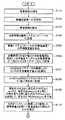
次に、本発明の第1の実施の形態に係る電源システムの制御方法について説明する。図6及び図7は、本実施の形態に係る電源システムの制御方法の処理手順を示すフローチャートである。 Next, a control method for the power supply system according to the first embodiment of the present invention will be described. 6 and 7 are flowcharts showing the processing procedure of the control method of the power supply system according to the present embodiment.
(a)図6のステップS101において、情報源装置110が周囲の気象情報を一定間隔で測定・収集する。気象情報の測定・収集は、例えば車、携帯電話等に搭載された情報源装置110で行われる。一定間隔で測定された気象情報に対して各種の演算処理が施され、時系列に記憶される。また、情報源装置110による測定・収集に代えて、気象庁、地方気象台、あるいは民間の気象情報提供機関からの気象情報を一定間隔で収集し、時系列に記憶しても良い。さらに、同時に複数の気象情報を測定・収集しても良い。 (A) In step S101 of FIG. 6, the
(b)ステップS102において、電源システム101〜105は気象情報の提供の要求先の情報源装置110を選択する。電源システム101〜105は、気象情報の提供要求可能な情報源装置110のうちから必要とする地域、例えば、各電源システム101〜105の付近に位置する情報源装置110を選択する。情報源装置110が1つの場合には、このような選択は不要であり、自動的にその情報源装置110からの提供を受けることになる。 (B) In step S <b> 102, the
(c)ステップS103において、上記のステップS102で選択された情報源装置110に対して、気象情報の提供を要求する。 (C) In step S103, the
(d)ステップS104において、気象情報の提供要求を受けた情報源装置110は気象情報をその要求を出した電源システム101〜105の受信部41に送信する。 (D) In step S104, the
(e)ステップS105において、電源システム101〜104の受信部41で受信された気象情報は電源システム101〜105の第1の演算記憶部42に出力される。第1の演算記憶部42では、その気象情報と発電装置1の発電量から発電装置1の今後の発電量(予測発電量)が予測され、記憶される。 (E) In step S105, the weather information received by the receiving
(f)ステップS106において、蓄電装置3の端子電圧と充放電電流を測定し、端子電圧データVDと充放電電流データID(充電方向であるのか、放電方向であるのかを示す符号C/Dを付した)とをペアデータとして記憶する。 (F) In step S106, the terminal voltage and the charge / discharge current of the
(g)ステップS107において、記憶されている端子電圧データVDと充放電電流データIDとのペアデータの積算により第1の所定期間D1(例えば、1日以下の期間)内の充放電電力量Qcdを算出する。 (G) In step S107, the charge / discharge power amount Qcd within the first predetermined period D1 (for example, a period of one day or less) is obtained by integrating the pair data of the stored terminal voltage data VD and charge / discharge current data ID. Is calculated.
(h)ステップS108において、ステップS107で算出された充放電電力量Qcdを第2の所定期間D2(例えば、少なくとも1年間)にわたって第1の所定期間D1(例えば、1日以下の期間)毎に時系列に記憶する。 (H) In step S108, the charge / discharge power amount Qcd calculated in step S107 is changed for each first predetermined period D1 (for example, a period of one day or less) over a second predetermined period D2 (for example, at least one year). Memorize in time series.
(i)ステップS109において、現在の日付と同じ過去の日付で記憶されている充放電電力量Qcd(pre1)と、現在の充放電電力量Qcd(now)とを比較して、現在の充放電電力が充電方向にあるのか、または放電方向にあるのか、また、現在の充放電電力が放電方向にある場合、放電電力量Qd(now)が増加傾向にあるのか、または減少傾向にあるのかを把握し、将来の日付と同じ過去の日付で記憶されている充放電電力量Qcd(pre2)を参照することにより、過去の日付と同じ将来の日付の第1の所定期間D1(例えば、1日以下の期間)内における充放電電力量Qcd(post)を予測する。 (I) In step S109, the current charge / discharge power amount Qcd (pre1) stored on the same past date as the current date is compared with the current charge / discharge power amount Qcd (now) to determine the current charge / discharge Whether the power is in the charge direction or the discharge direction, and if the current charge / discharge power is in the discharge direction, whether the discharge power amount Qd (now) is increasing or decreasing By grasping and referring to the charge / discharge power amount Qcd (pre2) stored on the same past date as the future date, the first predetermined period D1 (for example, one day) on the same future date as the past date The charge / discharge power amount Qcd (post) within the following period) is predicted.
(j)ステップS110において、充放電電流データIDの、第1の所定期間D1(例えば、1日以下の期間)にわたった積算により算出した積算容量Qを用いて蓄電装置3の現在の残存容量SOCを推定する。 (J) Current remaining capacity of the
(k)図7のステップS111において、予測した将来の充放電電力量Qcd(post)が放電電力量Qd(post)であるか否かを判定し、放電電力量Qd(post)でない、すなわち充電電力量Qc(post)である場合(ステップS511NO)、処理を終了する。 (K) In step S111 of FIG. 7, it is determined whether or not the predicted future charge / discharge power amount Qcd (post) is the discharge power amount Qd (post), and is not the discharge power amount Qd (post), that is, charging. If the amount of power is Qc (post) (NO in step S511), the process ends.
(l)ステップS112において、ステップS111の判断で、予測した将来の充放電電力量Qcd(post)が放電電力量Qd(post)である場合(ステップS111YES)、予測した将来の放電電力量Qd(post)が、発電装置1の将来の予測発電量Pge(post)に蓄電装置3の現在のSOCに対応する蓄電量を加算した供給可能電力量SPよりも大きいか否かを判定する。ステップS112の判断で、予測した将来の放電電力量Qd(post)が供給可能電力量SP以下である場合(ステップS112NO)、処理を終了する。 (L) In step S112, when the predicted future charge / discharge power amount Qcd (post) is the discharge power amount Qd (post) in step S111 (YES in step S111), the predicted future discharge power amount Qd ( It is determined whether or not (post) is greater than the suppliable power amount SP obtained by adding the power storage amount corresponding to the current SOC of the
(m)ステップS113において、ステップS112の判断で、予測した将来の放電電力量Qd(post)が供給可能電力量SPよりも大きい場合(ステップS512YES)、負荷装置2への蓄電装置3の放電電力量を下げる旨を負荷装置2に通知して、処理を終了する。 (M) In step S113, if the predicted future discharge power amount Qd (post) is larger than the suppliable power amount SP in step S112 (YES in step S512), the discharge power of the
以上説明したように、本発明の第1の実施の形態によれば、実際に測定された気象情報から今後の発電量を予測し、その予測発電量と過去のデータから今後入出力される電力量を予測する。このため、現状の蓄電装置3の状態量から将来の蓄電装置3の状態量を精度よく予想することが可能となる。したがって、現状の状態量から負荷装置2の消費電力モードを設定した従来の場合よりも、負荷装置2を蓄電装置3の状態量における将来の変動に応じて設定でき、負荷装置2を効率よく駆動できる。 As described above, according to the first embodiment of the present invention, the future power generation amount is predicted from the actually measured weather information, and the power to be input / output from the predicted power generation amount and past data in the future. Predict the amount. Therefore, it is possible to accurately predict the future state quantity of the
さらに、本発明の第1の実施の形態によれば、将来の蓄電装置3の状態量から、負荷装置2内の中で消費電力の大きな機能を切り離すことができる。それにより、最低限の機能のみで駆動させることで、負荷装置2をさらに長時間駆動させることも可能となる。 Furthermore, according to the first embodiment of the present invention, a function with large power consumption in the load device 2 can be separated from the state quantity of the
なお、本実施の形態においては、充放電制御装置4を測定部43、第1の演算記憶部42、第2の演算記憶部44、第3の演算記憶部45、制御部46、というように機能手段別に構成を分けているが、これらは、メモリを具備したマイクロコンピュータ等のように実構成上は一つになっても構わない。また、第1乃至第3の演算記憶部42、44、45はそれぞれが演算部と記憶部に分かれていても良い。測定部43も電圧測定部、電流測定部等それぞれの特性値ごとの測定を行う部分に分かれていても構わない。 In the present embodiment, the charge /
負荷装置2の駆動モードの決定主体は、充放電制御回路4に限定するものでなく、負荷装置2への電力供給量の情報を得て負荷装置2自体で行ってもよく、その他であっても問題ない。 The determination subject of the drive mode of the load device 2 is not limited to the charge /
負荷装置2の駆動状態を設定するのでなく、蓄電装置3に入出力可能な電力を算出し、算出された電力量に応じて、負荷装置2を駆動する態様としてもよい。 Instead of setting the drive state of the load device 2, it is possible to calculate the power that can be input to and output from the
SOCを算出する方法は、温度補正された電圧データから算出してもよく、上記の電流積算による算出方法との併用であってもよい。 The method for calculating the SOC may be calculated from the voltage data subjected to temperature correction, or may be used in combination with the above-described calculation method based on current integration.
電源システム101〜105の制御方法はプログラムをマイクロコンピュータ上で実行することで実現してもよい。すなわち、マイクロコンピュータに図6のステップS102〜図7のステップS113に示す各処理ステップを実現するための制御プログラムをインストールし、その制御プログラムを実行させることで実現可能である。 The control method of the
この制御プログラムをマイクロコンピュータによって読み込ませ、この制御プログラムを実行することによって、電源システム101〜105の制御方法を実現する。マイクロコンピュータの記憶部にこの制御プログラムをインストールし、この制御プログラムをマイクロコンピュータの演算部(Central Processing Unit:CPU)で実行させればよい。 The control method of the
(その他の実施の形態)
上記のように、本発明を第1の実施の形態によって記載したが、本発明はこれらの実施の形態に限られるものではない。(Other embodiments)
As described above, the present invention has been described according to the first embodiment, but the present invention is not limited to these embodiments.
本発明の第1の実施の形態では、図1の情報源装置110として、車両等の移動体や、気象庁等からの入手を示したが、電源システム101〜105自体に図1の情報源装置110の機能を持たせても良い。図8に、図3の電源システム101に図1の情報源装置110の機能をさらに追加した構成を示す。図8に示すように、この電源システム101bは、図3の構成に加えて、気象情報測定装置6をさらに備える。気象情報測定装置6は、周囲の気象情報を測定する気象情報測定部61と、一定間隔毎に測定された気象情報に対して各種演算し、格納する第4の演算記憶部62と、第4の演算記憶部62に格納された気象情報を他の電源システム102〜105に送信する第2の通信部63と、から構成されている。 In the first embodiment of the present invention, the
測定部61は一定間隔で周囲の気象情報を測定・収集する。測定部61は例えば温度計、湿度計、風速計等の周知の測定機器で構成すればよい。第4の演算記憶部62は測定された気象情報を用いて各種演算して気象情報を生成する。そして、通信部63は、通信回線100を介して、その気象情報を他の電源システム102〜105に送信する。気象情報測定装置6の測定部61及び第4の演算記憶部62は、メモリを具備したマイクロコンピュータ等のように実構成上は1つになっても構わない。第4の演算記憶部62は演算部と記憶部に分かれていても良い。また、充放電制御装置4の受信部41と気象情報測定装置6の通信部63は1つの構成になってもよい。さらに気象情報要求装置5の通信部53も加えて1つの構成でも構わない。 The
このように電源システム101〜105自体が図1の情報源装置110の機能を備えた場合には、お互いの情報源装置リスト52の一覧に他の電源システム101〜105及びその位置情報が加えられることになる。 As described above, when the
また、本発明の第1の実施の形態では、図1に示すように、通信回線100と、通信回線100に接続された電源システム101〜105とから成るネットワークシステムの構成を用いたが、本発明をこの構成は特に限定されるものでない。 In the first embodiment of the present invention, as shown in FIG. 1, the configuration of the network system including the
このように、本発明はここでは記載していない様々な実施の形態等を含むということを理解すべきである。 Thus, it should be understood that the present invention includes various embodiments and the like not described herein.
本発明に係るネットワークシステム、ネットワークシステムの電源システム制御方法及びその制御プログラムは、太陽電池などの自然エネルギーから発電する発電装置と組み合わされた電源システムに有効であり、産業上の利用可能性を有するものである。 INDUSTRIAL APPLICABILITY A network system, a network system power supply system control method, and a control program thereof according to the present invention are effective for a power supply system combined with a power generation device that generates power from natural energy such as a solar battery, and have industrial applicability. Is.
1 発電装置
2 負荷装置
3 蓄電装置
4 充放電制御装置
5 気象情報要求装置
6 気象情報測定装置
31 蓄電素子
32 電流センサ
41 受信部
42、44、45、62、1102 演算記憶部
43 測定部
46 制御部
51 情報源装置選択部
52 情報源装置リスト
54 情報源装置情報収集部
53、63、1103 通信部
61、1101 気象情報測定部
100 通信回線
101、101a、101b、102、103、104、105 電源システム
110 情報源装置
431 電圧検出部
432 電流検出部
433 記憶部
1104 位置情報保持部DESCRIPTION OF
Claims (12)
Translated fromJapanese前記電源システムは、自然エネルギーから電力を発電する発電装置と、
前記発電装置により発電された電力を貯蔵して負荷装置に電力を供給する蓄電装置と、
前記第1の通信回線に接続された第1の通信部と、
気象情報が必要な地域に位置する情報源装置に前記第1の通信部を用いて気象情報の提供を要求する気象情報要求装置と、
前記気象情報要求装置が気象情報の提供を要求した情報源装置から送信される気象情報を前記第1の通信部を用いて受信し、当該受信した気象情報に基づいて前記発電装置の今後の発電量を予測することにより、前記発電装置から前記蓄電装置への充電及び前記蓄電装置から前記負荷装置への放電を制御する充放電制御装置と、を備え、
前記情報源装置は、前記第1の通信回線に接続された第2の通信部と、
周囲の気象情報を測定する第1の気象情報測定部と、
前記気象情報測定部が測定する気象情報を記憶し、前記電源システムからの気象情報の提供の要求を前記第2の通信部を用いて受けると、記憶する気象情報を前記第2の通信部を用いて前記電源システムに送信する第1の気象情報記憶部と、を備えることを特徴とするネットワークシステム。A network system comprising: a power supply system; and at least one information source device connected to the power supply system via a first communication line and providing weather information to the power supply system,
The power supply system includes a power generation device that generates power from natural energy, and
A power storage device that stores power generated by the power generation device and supplies the load device with power; and
A first communication unit connected to the first communication line;
A weather information requesting device for requesting provision of weather information using the first communication unit to an information source device located in an area where weather information is required;
The weather information requesting device receives weather information transmitted from the information source device that requested the provision of weather information using the first communication unit, and based on the received weather information, future power generation of the power generation device A charge / discharge control device that controls charging from the power generation device to the power storage device and discharging from the power storage device to the load device by predicting an amount;
The information source device includes a second communication unit connected to the first communication line,
A first meteorological information measuring unit for measuring surrounding weather information;
Meteorological information measured by the meteorological information measuring unit is stored, and when a request for providing meteorological information from the power supply system is received using the second communication unit, the memorized weather information is stored in the second communication unit. And a first meteorological information storage unit used to transmit to the power supply system.
前記情報源装置リストに含まれる位置情報に基づいて気象情報が必要な地域に位置する情報源装置を選択する情報源装置選択部と、を備え、
前記気象情報要求装置は、前記情報源装置選択部が選択した情報源装置に、気象情報の提供を要求することを特徴とする請求項1に記載のネットワークシステム。The weather information requesting device includes an information source device list including location information indicating an area where an information source device capable of requesting provision of weather information is located;
An information source device selection unit that selects an information source device located in an area where weather information is required based on the position information included in the information source device list, and
The network system according to claim 1, wherein the weather information requesting device requests the information source device selected by the information source device selecting unit to provide weather information.
前記情報源装置リストは、前記情報源装置情報収集部が収集した位置情報を入力されると、当該位置情報を格納することを特徴とする請求項2に記載のネットワークシステム。The weather information requesting device collects position information indicating an area where the information source device is located from an information source device capable of requesting provision of weather information, and outputs an information source device information collecting unit to the information source device list In addition,
3. The network system according to claim 2, wherein the information source device list stores the position information when the position information collected by the information source device information collection unit is input.
前記位置情報が保持する自己の位置情報を前記第2の通信部を用いて前記電源システムに送信することを特徴とする請求項3に記載のネットワークシステム。The information source device further includes a position information holding unit that holds its own position information,
The network system according to claim 3, wherein the position information held by the position information is transmitted to the power supply system using the second communication unit.
前記気象情報測定装置は、周囲の気象情報を測定する第2の気象情報測定部と、
前記第2の気象情報測定部が測定する気象情報を記憶し、前記第2の通信回線に接続された他の電源システムからの気象情報の提供の要求を前記第1の通信部を用いて受けると、記憶する気象情報を前記第1の通信部を用いて前記他の電源システムに送信する第2の気象情報記憶部と、を備えることを特徴とする請求項1に記載のネットワークシステム。The power supply system is further connected to a second communication line using the first communication unit, and further includes a weather information measuring device,
The weather information measuring device includes a second weather information measuring unit that measures surrounding weather information;
Meteorological information measured by the second meteorological information measurement unit is stored, and a request for providing meteorological information from another power supply system connected to the second communication line is received using the first communication unit. The network system according to claim 1, further comprising: a second weather information storage unit that transmits the stored weather information to the other power supply system using the first communication unit.
前記蓄電装置の端子電圧及び充放電電流を測定する測定部と、
前記測定された端子電圧及び充放電電流に基づいて所定期間内の前記蓄電装置の電力量を算出して時系列電力量を記憶する第2の演算記憶部と、
前記測定された充放電電流に基づいて前記蓄電装置の残存容量を推定して記憶する第3の演算記憶部と、
前記予測発電量、時系列電力量及び残存容量に基づいて前記蓄電装置の前記負荷装置への放電電力量を制御する制御部と、を備えることを特徴とする請求項1〜5のいずれか1項に記載のネットワークシステム。The charge / discharge control device stores a predicted power generation amount by predicting a future power generation amount of the power generation device based on weather information transmitted from an information source device requested to provide weather information by the weather information requesting device. A first arithmetic storage unit
A measurement unit for measuring a terminal voltage and a charge / discharge current of the power storage device;
A second arithmetic storage unit that calculates the amount of power of the power storage device within a predetermined period based on the measured terminal voltage and charge / discharge current and stores the time-series power amount;
A third calculation storage unit that estimates and stores the remaining capacity of the power storage device based on the measured charge / discharge current;
The control part which controls the discharge electric energy to the said load apparatus of the said electrical storage apparatus based on the said predicted electric power generation amount, a time series electric energy, and a remaining capacity, The any one of Claims 1-5 provided The network system according to item.
前記第2の演算記憶部は、前記蓄電装置の端子電圧、充放電電流及び温度に基づいて前記蓄電装置の電力を算出することを特徴とする請求項6に記載のネットワークシステム。The measurement unit further measures the temperature of the power storage device,
The network system according to claim 6, wherein the second calculation storage unit calculates the power of the power storage device based on a terminal voltage, a charge / discharge current, and a temperature of the power storage device.
前記制御部は、前記蓄電装置の残存容量が所定値以下と判定され、かつ、前記負荷装置の今後の消費電力量がさらに増大すると予測された場合に、前記負荷装置の消費電力モードを前記省電力モードに移行することを特徴とする請求項6に記載のネットワークシステム。The load device has a plurality of power consumption modes including at least a normal power mode and a power saving mode,
When the remaining capacity of the power storage device is determined to be equal to or less than a predetermined value and the future power consumption of the load device is predicted to further increase, the control unit reduces the power consumption mode of the load device. The network system according to claim 6, wherein the network system shifts to a power mode.
気象情報の提供を要求可能な情報源装置が位置する地域を示す位置情報に基づいて、気象情報が必要な地域に位置する情報源装置を選択し、当該選択した情報源装置に、前記第1の通信回線を介して気象情報の提供を要求する第1のステップと、
前記第1のステップで気象情報の提供を要求した情報源装置から送信される気象情報を前記第1の通信回線を介して受信し、当該受信した気象情報に基づいて発電装置の今後の発電量を予測することにより、前記発電装置から蓄電装置への充電及び前記蓄電装置から負荷装置への放電を制御する第2のステップと
を含むことを特徴とするネットワークシステムの電源システム制御方法。A power system control method for a network system, comprising: a power system; and at least one information source device connected to the power system via a first communication line and providing weather information to the power system,
Based on the position information indicating the region where the information source device that can request the provision of weather information is located, the information source device located in the region where the weather information is required is selected, and the selected information source device includes the first information source device. A first step of requesting provision of weather information via a communication line of
Meteorological information transmitted from the information source device that requested provision of weather information in the first step is received via the first communication line, and the future power generation amount of the power generation device based on the received weather information And a second step of controlling charging from the power generation device to the power storage device and discharging from the power storage device to the load device by predicting
気象情報の提供を要求可能な情報源装置が位置する地域を示す位置情報に基づいて、気象情報が必要な地域に位置する情報源装置を選択し、当該選択した情報源装置に、前記第1の通信回線を介して気象情報の提供を要求する第1のステップと、
前記第1のステップで気象情報の提供を要求した情報源装置から送信される気象情報を前記第1の通信回線を介して受信し、当該受信した気象情報に基づいて発電装置の今後の発電量を予測することにより、前記発電装置から蓄電装置への充電及び前記蓄電装置から負荷装置への放電を制御する第2のステップと
を含むことを特徴とするネットワークシステムの電源システム制御プログラム。A computer executes a power system control method of a network system, comprising: a power system; and at least one information source device connected to the power system via a first communication line and providing weather information to the power system. A program for
Based on the position information indicating the region where the information source device that can request the provision of weather information is located, the information source device located in the region where the weather information is required is selected, and the selected information source device includes the first information source device. A first step of requesting provision of weather information via a communication line of
Meteorological information transmitted from the information source device that requested provision of weather information in the first step is received via the first communication line, and the future power generation amount of the power generation device based on the received weather information And a second step of controlling charging from the power generation device to the power storage device and discharging from the power storage device to the load device by predicting the power supply system.
Priority Applications (1)
| Application Number | Priority Date | Filing Date | Title |
|---|---|---|---|
| JP2006318150AJP2008136259A (en) | 2006-11-27 | 2006-11-27 | Network system, power supply system control method for network system, and control program therefor |
Applications Claiming Priority (1)
| Application Number | Priority Date | Filing Date | Title |
|---|---|---|---|
| JP2006318150AJP2008136259A (en) | 2006-11-27 | 2006-11-27 | Network system, power supply system control method for network system, and control program therefor |
Publications (1)
| Publication Number | Publication Date |
|---|---|
| JP2008136259Atrue JP2008136259A (en) | 2008-06-12 |
Family
ID=39560716
Family Applications (1)
| Application Number | Title | Priority Date | Filing Date |
|---|---|---|---|
| JP2006318150APendingJP2008136259A (en) | 2006-11-27 | 2006-11-27 | Network system, power supply system control method for network system, and control program therefor |
Country Status (1)
| Country | Link |
|---|---|
| JP (1) | JP2008136259A (en) |
Cited By (6)
| Publication number | Priority date | Publication date | Assignee | Title |
|---|---|---|---|---|
| WO2012050014A1 (en) | 2010-10-15 | 2012-04-19 | 三洋電機株式会社 | Power management system |
| JP2012138335A (en)* | 2010-12-09 | 2012-07-19 | Sony Corp | Nonaqueous electrolyte secondary battery and nonaqueous electrolyte, battery pack, electronic device, electric vehicle, power storage device, and power system |
| JP2013042627A (en)* | 2011-08-18 | 2013-02-28 | Ntt Docomo Inc | Dc power supply control device and dc power supply control method |
| JP2013045252A (en)* | 2011-08-23 | 2013-03-04 | Panasonic Corp | Energy management system |
| US8788110B2 (en) | 2010-09-08 | 2014-07-22 | Sanyo Electric Co., Ltd. | Electric power visualization method and electric power visualization device |
| US8836285B2 (en) | 2010-08-23 | 2014-09-16 | Sanyo Electric Co., Ltd. | Power management system |
Citations (9)
| Publication number | Priority date | Publication date | Assignee | Title |
|---|---|---|---|---|
| JPH04200245A (en)* | 1990-11-29 | 1992-07-21 | Misawa Homes Co Ltd | Solar cell system |
| JPH098676A (en)* | 1995-06-20 | 1997-01-10 | Nippon Denki Musen Denshi Kk | Radio communication feed system |
| JP2000125407A (en)* | 1998-10-15 | 2000-04-28 | Toyota Motor Corp | Vehicle charge control device |
| JP2000324716A (en)* | 1999-04-30 | 2000-11-24 | Haneda Hume Pipe Co Ltd | Solar battery apparatus |
| JP2003032890A (en)* | 2001-07-19 | 2003-01-31 | Senaa Kk | Load power controller |
| JP2004032989A (en)* | 2002-04-30 | 2004-01-29 | Atsushi Iga | Storage battery capacity of system combined with storage battery in solar cell, merit calculation method, and storage battery charge discharge employment method |
| JP2004064885A (en)* | 2002-07-29 | 2004-02-26 | Omron Corp | Power supply management system using solar cell as power supply, and information apparatus using the same |
| JP2005300176A (en)* | 2004-04-06 | 2005-10-27 | Matsushita Electric Ind Co Ltd | Mobile portable terminal, communication host device, and weather prediction system |
| JP2006267014A (en)* | 2005-03-25 | 2006-10-05 | Nec Lamilion Energy Ltd | Secondary battery remaining capacity estimation method, apparatus and battery pack |
- 2006
- 2006-11-27JPJP2006318150Apatent/JP2008136259A/enactivePending
Patent Citations (9)
| Publication number | Priority date | Publication date | Assignee | Title |
|---|---|---|---|---|
| JPH04200245A (en)* | 1990-11-29 | 1992-07-21 | Misawa Homes Co Ltd | Solar cell system |
| JPH098676A (en)* | 1995-06-20 | 1997-01-10 | Nippon Denki Musen Denshi Kk | Radio communication feed system |
| JP2000125407A (en)* | 1998-10-15 | 2000-04-28 | Toyota Motor Corp | Vehicle charge control device |
| JP2000324716A (en)* | 1999-04-30 | 2000-11-24 | Haneda Hume Pipe Co Ltd | Solar battery apparatus |
| JP2003032890A (en)* | 2001-07-19 | 2003-01-31 | Senaa Kk | Load power controller |
| JP2004032989A (en)* | 2002-04-30 | 2004-01-29 | Atsushi Iga | Storage battery capacity of system combined with storage battery in solar cell, merit calculation method, and storage battery charge discharge employment method |
| JP2004064885A (en)* | 2002-07-29 | 2004-02-26 | Omron Corp | Power supply management system using solar cell as power supply, and information apparatus using the same |
| JP2005300176A (en)* | 2004-04-06 | 2005-10-27 | Matsushita Electric Ind Co Ltd | Mobile portable terminal, communication host device, and weather prediction system |
| JP2006267014A (en)* | 2005-03-25 | 2006-10-05 | Nec Lamilion Energy Ltd | Secondary battery remaining capacity estimation method, apparatus and battery pack |
Cited By (6)
| Publication number | Priority date | Publication date | Assignee | Title |
|---|---|---|---|---|
| US8836285B2 (en) | 2010-08-23 | 2014-09-16 | Sanyo Electric Co., Ltd. | Power management system |
| US8788110B2 (en) | 2010-09-08 | 2014-07-22 | Sanyo Electric Co., Ltd. | Electric power visualization method and electric power visualization device |
| WO2012050014A1 (en) | 2010-10-15 | 2012-04-19 | 三洋電機株式会社 | Power management system |
| JP2012138335A (en)* | 2010-12-09 | 2012-07-19 | Sony Corp | Nonaqueous electrolyte secondary battery and nonaqueous electrolyte, battery pack, electronic device, electric vehicle, power storage device, and power system |
| JP2013042627A (en)* | 2011-08-18 | 2013-02-28 | Ntt Docomo Inc | Dc power supply control device and dc power supply control method |
| JP2013045252A (en)* | 2011-08-23 | 2013-03-04 | Panasonic Corp | Energy management system |
Similar Documents
| Publication | Publication Date | Title |
|---|---|---|
| TWI583577B (en) | Battery exchange system for electric vehicles | |
| JP7040601B2 (en) | Battery control device, battery control method, uninterruptible power supply, power system and electric vehicle | |
| JP5062294B2 (en) | Energy management system | |
| JP5353957B2 (en) | Power supply system | |
| US10123390B2 (en) | Energy management control for solar-powered lighting devices | |
| JP2008134060A (en) | Storage device abnormality detection device, storage device abnormality detection method, and abnormality detection program thereof | |
| WO2008053969A1 (en) | Abnormality detecting device for storage element, abnormality detecting method for storage element, abnormality detecting program for storage element, and computer-readable recording medium containing abnormality detecting program for storage element is recorded | |
| JP2012222860A (en) | Power supply system | |
| JP2008136259A (en) | Network system, power supply system control method for network system, and control program therefor | |
| KR101962539B1 (en) | Method and Apparatus for Predicting Power Demand and Apparatus and Method for Controlling Charge/Discharge of ESS based on It | |
| JP2008086109A (en) | Power supply system, network system, network system control method, and network system power supply system control program | |
| JP2012239357A (en) | Battery pack, electronic apparatus, electric power system and electric vehicle | |
| US20210300204A1 (en) | Power calculation apparatus and power calculation method | |
| JP2008043148A (en) | Power supply system, control method and program for power supply system | |
| JP2010213507A (en) | Natural energy integrated power storage system and natural energy integrated power storage method | |
| JP2004327448A (en) | Power supply systems, apartments, and programs | |
| JP6172346B1 (en) | Energy management system | |
| US20210304300A1 (en) | Bid management apparatus and bid management method | |
| KR101646730B1 (en) | System and method for estimating soc of sodium rechargeable battery | |
| JP2021016284A (en) | Control apparatus | |
| JP2008043147A (en) | Power supply system, control method and program for power supply system | |
| JP6082586B2 (en) | Energy management apparatus, energy management system, and energy management method | |
| JP2013042575A (en) | Power generation amount predictor, server, and power generating system | |
| JP2014195386A (en) | Photovoltaic power generation system | |
| JP2012065421A (en) | Device, method, and program for charge control |
Legal Events
| Date | Code | Title | Description |
|---|---|---|---|
| A621 | Written request for application examination | Free format text:JAPANESE INTERMEDIATE CODE: A621 Effective date:20091120 | |
| A977 | Report on retrieval | Free format text:JAPANESE INTERMEDIATE CODE: A971007 Effective date:20100902 | |
| A131 | Notification of reasons for refusal | Free format text:JAPANESE INTERMEDIATE CODE: A131 Effective date:20100928 | |
| A02 | Decision of refusal | Free format text:JAPANESE INTERMEDIATE CODE: A02 Effective date:20110208 |