JP2008135955A - ROF system and slave station apparatus installation method - Google Patents
ROF system and slave station apparatus installation methodDownload PDFInfo
- Publication number
- JP2008135955A JP2008135955AJP2006320372AJP2006320372AJP2008135955AJP 2008135955 AJP2008135955 AJP 2008135955AJP 2006320372 AJP2006320372 AJP 2006320372AJP 2006320372 AJP2006320372 AJP 2006320372AJP 2008135955 AJP2008135955 AJP 2008135955A
- Authority
- JP
- Japan
- Prior art keywords
- station device
- slave station
- master station
- optical signal
- slave
- Prior art date
- Legal status (The legal status is an assumption and is not a legal conclusion. Google has not performed a legal analysis and makes no representation as to the accuracy of the status listed.)
- Pending
Links
Images


Landscapes
- Mobile Radio Communication Systems (AREA)
Abstract
Translated fromJapaneseDescription
Translated fromJapaneseこの発明は、携帯電話システムの不感エリアをカバーするROF(Radio Over Fiber)システムおよび子局装置設置方法に関する。 The present invention relates to a ROF (Radio Over Fiber) system that covers a dead area of a mobile phone system and a slave station apparatus installation method.
近時、携帯電話システムの不感地対策、あるいは携帯電話基地局のカバーエリアの拡大等を目的として、携帯電話基地局とアンテナとの間をROFシステムにて接続する技術の適用が進んでいる。 In recent years, the application of technology for connecting a mobile phone base station and an antenna by an ROF system has been advanced for the purpose of countermeasures for the dead zone of the mobile phone system or expanding the cover area of the mobile phone base station.
光ファイバは伝送損失が小さいため、ROF技術を用いることにより、数kmの範囲にわたってアンテナを配置することが可能になる。さらにROF技術は、高層ビルやイベントホール等の電波不感エリアをカバーするために、カバーエリアが狭いアンテナを複数分散配置して不感エリア対策を行う場合などにおいても有効に利用できる。 Since an optical fiber has a small transmission loss, an antenna can be arranged over a range of several kilometers by using ROF technology. Further, the ROF technology can be effectively used when a dead area countermeasure is taken by distributing a plurality of antennas having a narrow cover area in order to cover a radio dead area such as a high-rise building or an event hall.
従来、高層ビルにおける電波不感エリアをカバーするためのROFシステムは、携帯電話端末との間で送受信される無線通信信号を送受信する携帯電話基地局に接続され、その無線通信信号を光信号に変換して子局装置との間で通信する親局装置と、光信号を無線通信信号へ再変換してアンテナを介して携帯電話端末との間で無線通信を行う子局装置とを具備している。 Conventionally, an ROF system for covering a radio wave insensitive area in a high-rise building is connected to a mobile phone base station that transmits and receives a radio communication signal transmitted to and received from a mobile phone terminal, and converts the radio communication signal into an optical signal. A master station device that communicates with the slave station device, and a slave station device that reconverts the optical signal into a wireless communication signal and performs wireless communication with the mobile phone terminal via the antenna. Yes.
このシステムでは、ビルの地下等に設置された携帯電話基地局の近傍に、親局装置が設置され、この親局装置には無線通信信号が上り/下り方向で接続される。親局装置には光ファイバを介して複数の子局装置がスター状に接続されており、無線通信信号は親局装置により光信号に変換されて光ファイバに伝送されている。これらの光信号は、光ファイバを介してビルの各フロアに分散配置された子局装置との間で入出力され、子局装置により無線通信信号へ再度変換される。その後、この無線通信信号は、子局装置に設置されたアンテナを介して携帯電話端末との間で送受信される。このように、小さなカバーエリアの子局装置を複数設置して組み合わせたROFシステムにより、高層ビル等における携帯電話の不感エリア対策を行っている。 In this system, a master station device is installed in the vicinity of a mobile phone base station installed in the basement of a building, and wireless communication signals are connected to the master station device in the up / down direction. A plurality of slave station devices are connected to the master station device via an optical fiber in a star shape, and a radio communication signal is converted into an optical signal by the master station device and transmitted to the optical fiber. These optical signals are input / output to / from slave station devices distributed on each floor of the building via optical fibers, and are converted again to wireless communication signals by the slave station devices. Thereafter, the wireless communication signal is transmitted / received to / from the mobile phone terminal via an antenna installed in the slave station device. In this way, measures against dead areas of mobile phones in high-rise buildings and the like are performed by an ROF system in which a plurality of slave station devices with small cover areas are installed and combined.
しかしながら、このシステムでは、親局装置の障害時やメンテナンスを行う際にシステム全体の機能が停止するという問題がある。例えば、カバーエリアを拡大するために子局装置を増設する場合等には、電波強度に関する規制により一旦サービスを停止して、言い換えれば電波の送信を停止して、基準信号によるレベル調整等を行うことが必要となる。この作業中にはサービスを提供することができなくなる。 However, in this system, there is a problem that the function of the entire system stops when the master station apparatus fails or when maintenance is performed. For example, when adding a slave station device to expand the cover area, the service is temporarily stopped due to restrictions on radio wave intensity, in other words, the transmission of radio waves is stopped, and level adjustment based on the reference signal is performed. It will be necessary. During this work, services cannot be provided.
なお、基地局に障害が発生したときの通信不能を回避するため、隣接する基地局が、通信不能となった基地局のカバーエリアを補完する方法が提案されている(例えば、特許文献1参照。)。この文献1では、隣接する基地局のカバーエリアの形状を変形して、通信不能となった基地局のカバーエリアを補完している。しかし、上述するシステム全体の機能停止を回避する限りにおいては、文献1に示すようなカバーエリアの形状を変形する必要は無く、カバーエリア全体の中で部分的にサービスが継続していれば十分である。また、カバーエリアの形状を変化させる機能を基地局に持たせると、そのコストが高くなる。
以上のように、従来のROFシステムでは、親局装置の障害時やメンテナンスを行う際にはROFシステム全体の機能が停止してしまい、この間のサービスの提供ができなかった。 As described above, in the conventional ROF system, the function of the entire ROF system is stopped at the time of failure of the master station apparatus or when maintenance is performed, and the service during this period cannot be provided.
そこで、本発明の目的は、従来のシステムと比較してシステムのコストを上げること無しに、障害時のインパクトを回避することが可能なROFシステムおよび子局装置設置方法を提供することである。 Accordingly, an object of the present invention is to provide an ROF system and a slave station apparatus installation method capable of avoiding an impact at the time of failure without increasing the cost of the system as compared with a conventional system.
上記目的を達成するために本発明は、移動端末との間で通信する無線信号を送受信する基地局と、前記無線信号を第1及び第2の系統に分岐する分岐部と、前記第1及び第2の系統の無線信号それぞれを複数の光信号に変換して入出力する第1及び第2の親局装置と、前記第1及び第2の親局装置との間でそれぞれが入出力する複数の光信号それぞれを無線信号に変換し、それぞれのアンテナを介して前記移動端末との間で無線通信する複数の子局装置とを具備し、前記基地局と前記移動端末との間の通信を可能とする空間を、前記第1の親局装置からの光信号を入出力する子局装置と前記第2の親局装置からの光信号を入出力する子局装置とを混在して設置することにより構成される。 In order to achieve the above object, the present invention provides a base station that transmits and receives a radio signal communicated with a mobile terminal, a branching unit that branches the radio signal into first and second systems, and the first and second Each of the second system radio signals is converted into a plurality of optical signals and input / output between the first and second master station devices and the first and second master station devices, respectively. Communication between the base station and the mobile terminal, comprising a plurality of slave station devices that convert each of a plurality of optical signals into radio signals and wirelessly communicate with the mobile terminal via respective antennas Is installed in a mixture of a slave station device that inputs and outputs an optical signal from the first master station device and a slave station device that inputs and outputs an optical signal from the second master station device. It is constituted by doing.
このようにして、基地局からの1系統の無線信号を2系統に分岐して2台の親局装置に出力する。これら2台の親局装置にて変換した光信号を、光ファイバを介して同一エリア内の子局装置に伝送することにより、同一エリア内を2系統の信号で独立に運用できるようにしている。 In this way, one system of radio signals from the base station is branched into two systems and output to the two master station devices. By transmitting the optical signals converted by these two master station devices to the slave station devices in the same area via optical fibers, the same area can be operated independently with two signals. .
本発明によれば、2系統に分岐した無線信号を2台の親局装置との間で入出力することにより、同一フロア内を2系統の信号で独立に運用できるため、片方の系統に障害が発生したときやメンテナンス時にも、当該フロアにおいてサービスの提供を継続することが可能となる。また、光ファイバ、子局装置、アンテナの数は変わらないため、システムの費用が従来のシステムと比較して高額にはならない。 According to the present invention, by inputting / outputting radio signals branched into two systems to / from two master station devices, the same floor can be operated independently with two systems of signals. It is possible to continue providing services on the floor even when a problem occurs or during maintenance. In addition, since the number of optical fibers, slave station devices, and antennas does not change, the cost of the system does not increase compared to the conventional system.
以下、図面を参照しながら本発明の実施の形態について詳細に説明する。 Hereinafter, embodiments of the present invention will be described in detail with reference to the drawings.
図1は、本発明の一実施形態に係るROFシステム1の概略構成を示すブロック図である。図1におけるROFシステム1は、無線信号の一つである無線通信信号を送受信する携帯電話基地局2と、送受信する無線通信信号の分岐および結合を行う分岐結合器3と、分岐結合部3でa,b系統に分岐された各無線通信信号を複数の光信号に変換する親局装置a,bと、光信号を伝送する光ファイバ4と、光信号を受信して無線通信信号へ変換する子局装置a−1〜a−N,b−1〜b−Nと、子局装置a−1〜a−N,b−1〜b−Nで変換された無線通信信号を放射するアンテナa1−1〜a1−N,b1−1〜b1−Nとを具備する。 FIG. 1 is a block diagram showing a schematic configuration of an
携帯電話端末T1〜TNは、アンテナa1−1〜a1−N,b1−1〜b1−Nのいずれかを介し、子局装置a−1〜a−N,b−1〜b−Nのいずれかとの間で無線通信を行う。 The mobile phone terminals T1 to TN are connected to any one of the slave station devices a-1 to aN and b-1 to bN via any one of the antennas a1-1 to a1-N, b1-1 to b1-N. Wireless communication is performed between the heels.
図2は、本発明の一実施形態に係るROFシステム1を高層ビルに設置したときの概略構成を示す模式図である。図2に示すROFシステム1において、ビルの地下等に設置された一台の携帯電話基地局2が、分岐結合器3を介して第1及び第2の親局装置a,bと接続され、高層階まで設置された光ファイバ4により、各フロアに配置した子局装置a−1〜a−N,b−1〜b−Nと接続されている。各子局装置には、アンテナa1−1〜a1−N,b1−1〜b1−Nが設置される。このとき、光ファイバ4は、複数の細い光ファイバが束ねられた構成をしており、親局装置aからのa系統の光信号を伝送する光ファイバ4aと、親局装置bからのb系統の光信号を伝送する光ファイバ4bとが存在する。子局装置a−1〜a−Nは、光ファイバ4aによって親局装置aに対してスター状に接続される。子局装置b−1〜b−Nと親局装置bとの接続トポロジも同様である。また、親局装置a,bから光ファイバを各フロアに分配するに際して、各フロアにおいて親局装置aと接続する子局装置a−1〜a−Nのカバーエリアと、親局装置bと接続する子局装置b−1〜b−Nのカバーエリアとが交互になるよう配置される。 FIG. 2 is a schematic diagram showing a schematic configuration when the
携帯電話基地局2から送信された無線通信信号は、分岐結合器3によりa,bの2系統に分岐され、第1及び第2の親局装置a,bに入力される。このとき、分岐結合器3と第1及び第2の親局装置a,bとには、無線通信信号が上り/下り方向で接続される。 The wireless communication signal transmitted from the mobile
以下、説明の便宜上、下り方向の無線通信信号を出力(送信)する場合を例に動作を説明する。 Hereinafter, for convenience of explanation, the operation will be described by taking as an example the case of outputting (transmitting) a downlink radio communication signal.
親局装置a,bにおいて無線通信信号は光信号に変換され、親局装置aからは光ファイバ4aを介してa系統の光信号が各フロアの子局装置a−1〜a−Nに伝送され、親局装置bからは光ファイバ4bを介してb系統の光信号が各フロアの子局装置b−1〜b−Nに伝送される。この光ファイバは上り/下り2本で接続する場合も、波長多重により一本の光ファイバの場合もある。子局装置a−1〜a−Nに出力された光信号は、無線通信信号に再度変換され、子局装置a−1〜a−Nに設置されたアンテナa1−1〜a1−Nから放射される。同様に、子局装置b−1〜b−Nに出力された光信号は、無線通信信号に再度変換され、子局装置b−1〜b−Nに設置されたアンテナb1−1〜b1−Nから放射される。 In the master station devices a and b, the wireless communication signal is converted into an optical signal, and the master station device a transmits an a-system optical signal to the slave station devices a-1 to a-N on each floor via the
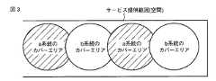
図3は、本発明の一実施形態に係るROFシステム1の、図2におけるa系統のカバーエリアとb系統のカバーエリアの模式図である。各フロアでのサービス提供範囲において、アンテナa1−1〜a1−Nから放射されるa系統のカバーエリアと、アンテナb1−1〜b1−Nから放射されるb系統のカバーエリアとを空間に交互に配置するようにする。 FIG. 3 is a schematic diagram of the cover area of the a system and the cover area of the b system in FIG. 2 of the
以上のように、上記一実施形態では、携帯電話基地局2からの出力1系統が2系統となるよう親局装置a,bの2台を接続して分岐することにより、それぞれの系統の信号を独立して運用できるようにしている。この構成では、同一エリアにおいて2系統の親局装置a,bからの光信号が、子局装置a−1〜a−N,b−1〜b−Nにて無線通信信号に変換され、アンテナa1−1〜a1−N,b1−1〜b1−Nから放射される。これにより、親局装置a,bは、従来の親局装置と比較して半分のチャネル容量となるものを2台準備すれば十分である。すなわち、チャネル容量が半分の親局装置でよいため、親局装置が2台必要になるとはいえ、そのコストは、1台のときと比較して単純に2倍となることはない。また、光ファイバ、子局装置、およびアンテナの数は従来のシステムと同じである。つまり、従来のシステムと比較してコストが増加するのは親局装置のコストのみなので、極端なシステムコストの増大をきたさない。 As described above, in the above embodiment, by connecting and branching two of the master station devices a and b so that one output from the mobile
したがって、a系統の親局装置aのシステムのメンテナンスや修理をするときには、b系統の親局装置bが作動しており、停止した親局装置aのカバーエリアが櫛状に抜けるだけなので、サービスを提供できるエリアを残しておくことができる。また逆に、b系統の親局装置bがシステム作業の際には、a系統の親局装置aでサービスを継続することが可能になり、全断を発生させることがない。これにより、携帯電話端末T1〜TNのユーザは、使用中のカバーエリアがサービス停止となっても、少し移動するだけでサービスが継続されている片系のカバーエリアにて、携帯電話端末T1〜TNによる無線通信を継続することが可能となる。また、基地局に障害が生じる確率は低く、基地局自体が高額であるため、基地局を複数台用意して高層ビル等におけるROFシステム全体の機能停止に備えるよりも経済的である。なお、上述のように従来のシステムと比較して、多少のコストの増大はあるが、メンテナンス負担の軽減、システム変更時のインパクト軽減の効果の方がはるかに大きいため、経済的なシステムであることには変わりない。 Accordingly, when performing maintenance or repair of the system of the a-system master station device a, the b-system master station device b is operating, and the cover area of the stopped master station device a is simply removed in a comb shape. You can leave an area where you can provide. On the other hand, when the master station device b of the b system performs system work, the service can be continued with the master station apparatus a of the a system, and no interruption occurs. As a result, the user of the mobile phone terminal T1 to TN can use the mobile phone terminal T1 to T1 in the one-side cover area in which the service is continued only by moving a little even if the service area is stopped. Wireless communication by TN can be continued. In addition, since the probability of failure of the base station is low and the base station itself is expensive, it is more economical than preparing a plurality of base stations and preparing for the outage of the entire ROF system in a high-rise building or the like. As described above, although there is a slight increase in cost compared to the conventional system, it is an economical system because the effects of reducing the maintenance burden and impact when changing the system are much greater. It does not change.
図4は、従来の方法によるROFシステム1の概略構成例を示すブロック図である。また、図5は、従来の方法によるROFシステム1を高層ビルに設置したときの概略構成例を示す模式図である。なお、図4及び5において、図1及び2と同一部分には同一符号を付して示し、ここでは重複する説明を省略する。 FIG. 4 is a block diagram showing a schematic configuration example of the
図5に示すROFシステム1において、一台の携帯電話基地局2から送信される無線通信信号は、親局装置cで1系統の光信号に変換され、光ファイバ4を介して複数の子局装置c−1〜c−Nへ伝送される。このとき、親局装置cからの光信号を各フロアに伝送するに際して、光信号は、各フロアにおいて空間的に均等に設置された子局装置に伝送される。 In the
従来技術では、親局装置cが1系統であるため、親局装置cの障害時やメンテナンスを行う際にはROFシステム1全体の機能が停止してしまう。 In the prior art, since the master station device c is one system, the function of the
これに対し、本発明では、2系統の親局装置a,bを接続しているため、片方の親局装置に障害がある場合やメンテナンスのときにサービスが全断されることはない。 On the other hand, in the present invention, since the two parent station devices a and b are connected, the service is not completely interrupted when there is a failure in one of the parent station devices or during maintenance.
なお、本発明は上記実施形態に限定されるものではない。例えば上記実施形態では、a系統の子局装置a−1〜a−Nのカバーエリアと、b系統の子局装置b−1〜b−Nのカバーエリアとが交互になるよう配置される例について説明したが、交互配置ではなく、a系統の子局装置のカバーエリアとb系統の子局装置のカバーエリアとが分散されて配置される場合でも同様に実施可能である。この場合における無線信号を必要とする空間の実施例としては、例えば、イベントホールや地下街等の一層に広い空間への設置が挙げられる。 The present invention is not limited to the above embodiment. For example, in the above-described embodiment, the cover areas of the a-system slave station devices a-1 to a-N and the b-system slave station devices b-1 to b-N are alternately arranged. However, the present invention can be similarly applied even when the cover area of the a-system slave station device and the cover area of the b-system slave station device are distributed and arranged instead of being alternately arranged. As an example of the space that requires a radio signal in this case, for example, installation in a wider space such as an event hall or an underground mall can be mentioned.
また、上記実施形態では、基地局2からの信号が2系統に分岐される例について説明したが、この系統の数に制限は無く、複数の系統である場合でも同様に実施可能である。 In the above embodiment, an example in which the signal from the
さらに、本発明は上記実施形態そのままに限定されるものではなく、実施段階ではその要旨を逸脱しない範囲で構成要素を変形して具体化できる。また、上記実施形態に開示されている複数の構成要素の適宜な組み合わせにより、種々の発明を形成できる。例えば、実施形態に示される全構成要素から幾つかの構成要素を削除してもよい。 Furthermore, the present invention is not limited to the above-described embodiment as it is, and can be embodied by modifying the constituent elements without departing from the scope of the invention in the implementation stage. In addition, various inventions can be formed by appropriately combining a plurality of constituent elements disclosed in the embodiment. For example, some components may be deleted from all the components shown in the embodiment.
1…ROFシステム、2…携帯電話基地局、3…分岐結合器、4,4a,4b…光ファイバ、a,b…親局装置、a−1〜a−N,b−1〜b−N…子局装置、a1−1〜a1−N,b1−1〜b1−N…アンテナ、T1〜TN…携帯電話端末 DESCRIPTION OF
Claims (4)
Translated fromJapanese前記無線信号を第1及び第2の系統に分岐する分岐部と、
前記第1及び第2の系統の無線信号それぞれを複数の光信号に変換して入出力する第1及び第2の親局装置と、
前記第1及び第2の親局装置との間でそれぞれが入出力する複数の光信号それぞれを無線信号に変換し、それぞれのアンテナを介して前記移動端末との間で無線通信する複数の子局装置とを具備し、
前記基地局と前記移動端末との間の通信を可能とする空間を、前記第1の親局装置からの光信号を入出力する子局装置と前記第2の親局装置からの光信号を入出力する子局装置とを混在して設置することにより構成することを特徴とするROFシステム。A base station that transmits and receives radio signals to and from mobile terminals;
A branching section for branching the radio signal into first and second systems;
First and second master station devices that convert each of the first and second wireless signals into a plurality of optical signals and input / output;
A plurality of slaves that convert each of a plurality of optical signals input / output to / from the first and second master station devices into radio signals and perform radio communication with the mobile terminal via the respective antennas Station equipment,
In a space enabling communication between the base station and the mobile terminal, an optical signal from the slave station device that inputs / outputs an optical signal from the first master station device and an optical signal from the second master station device An ROF system configured by installing a mixture of slave station devices for input and output.
前記基地局と前記移動端末との間の通信を可能とする空間を、前記第1の親局装置からの光信号を入出力する子局装置と前記第2の親局装置からの光信号を入出力する子局装置とを混在して設置することにより構成することを特徴とする子局装置設置方法。A base station that transmits and receives radio signals to be communicated with a mobile terminal; a branching unit that branches the radio signals into first and second systems; and a plurality of radio signals of the first and second systems A plurality of optical signals respectively output between the first and second master station devices that convert to optical signals and input / output and the first and second master station devices are converted into radio signals. A method of installing the slave station device used in an ROF system comprising a plurality of slave station devices that wirelessly communicate with the mobile terminal via respective antennas,
In a space enabling communication between the base station and the mobile terminal, an optical signal from the slave station device that inputs / outputs an optical signal from the first master station device and an optical signal from the second master station device A method for installing a slave station device, comprising: installing a slave station device that inputs and outputs in a mixed manner.
Priority Applications (1)
| Application Number | Priority Date | Filing Date | Title |
|---|---|---|---|
| JP2006320372AJP2008135955A (en) | 2006-11-28 | 2006-11-28 | ROF system and slave station apparatus installation method |
Applications Claiming Priority (1)
| Application Number | Priority Date | Filing Date | Title |
|---|---|---|---|
| JP2006320372AJP2008135955A (en) | 2006-11-28 | 2006-11-28 | ROF system and slave station apparatus installation method |
Publications (1)
| Publication Number | Publication Date |
|---|---|
| JP2008135955Atrue JP2008135955A (en) | 2008-06-12 |
Family
ID=39560491
Family Applications (1)
| Application Number | Title | Priority Date | Filing Date |
|---|---|---|---|
| JP2006320372APendingJP2008135955A (en) | 2006-11-28 | 2006-11-28 | ROF system and slave station apparatus installation method |
Country Status (1)
| Country | Link |
|---|---|
| JP (1) | JP2008135955A (en) |
Cited By (6)
| Publication number | Priority date | Publication date | Assignee | Title |
|---|---|---|---|---|
| JP2016197899A (en)* | 2010-08-17 | 2016-11-24 | ダリ システムズ カンパニー リミテッド | Daisy chain ring of remote unit for distributed antenna system |
| US9820171B2 (en) | 2010-09-14 | 2017-11-14 | Dali Wireless, Inc. | Remotely reconfigurable distributed antenna system and methods |
| US10080178B2 (en) | 2006-12-26 | 2018-09-18 | Dali Wireless, Inc. | Distributed antenna system |
| US11159129B2 (en) | 2002-05-01 | 2021-10-26 | Dali Wireless, Inc. | Power amplifier time-delay invariant predistortion methods and apparatus |
| US11297603B2 (en) | 2010-08-17 | 2022-04-05 | Dali Wireless, Inc. | Neutral host architecture for a distributed antenna system |
| US11418155B2 (en) | 2002-05-01 | 2022-08-16 | Dali Wireless, Inc. | Digital hybrid mode power amplifier system |
- 2006
- 2006-11-28JPJP2006320372Apatent/JP2008135955A/enactivePending
Cited By (19)
| Publication number | Priority date | Publication date | Assignee | Title |
|---|---|---|---|---|
| US11418155B2 (en) | 2002-05-01 | 2022-08-16 | Dali Wireless, Inc. | Digital hybrid mode power amplifier system |
| US11159129B2 (en) | 2002-05-01 | 2021-10-26 | Dali Wireless, Inc. | Power amplifier time-delay invariant predistortion methods and apparatus |
| US11006343B2 (en) | 2006-12-26 | 2021-05-11 | Dali Wireless, Inc. | Distributed antenna system |
| US11818642B2 (en) | 2006-12-26 | 2023-11-14 | Dali Wireless, Inc. | Distributed antenna system |
| US10080178B2 (en) | 2006-12-26 | 2018-09-18 | Dali Wireless, Inc. | Distributed antenna system |
| US10334499B2 (en) | 2006-12-26 | 2019-06-25 | Dali Wireless, Inc. | Distributed antenna system |
| JP2016197899A (en)* | 2010-08-17 | 2016-11-24 | ダリ システムズ カンパニー リミテッド | Daisy chain ring of remote unit for distributed antenna system |
| US11297603B2 (en) | 2010-08-17 | 2022-04-05 | Dali Wireless, Inc. | Neutral host architecture for a distributed antenna system |
| US10159074B2 (en) | 2010-09-14 | 2018-12-18 | Dali Wireless, Inc. | Remotely reconfigurable distributed antenna system and methods |
| US10743317B1 (en) | 2010-09-14 | 2020-08-11 | Dali Wireless, Inc. | Remotely reconfigurable distributed antenna system and methods |
| US11013005B2 (en) | 2010-09-14 | 2021-05-18 | Dali Wireless, Inc. | Remotely reconfigurable distributed antenna system and methods |
| KR102136940B1 (en)* | 2010-09-14 | 2020-07-23 | 달리 시스템즈 씨오. 엘티디. | Remotely Reconfigurable Distributed Antenna System and Methods |
| US10701695B2 (en) | 2010-09-14 | 2020-06-30 | Dali Wireless, Inc. | Remotely reconfigurable distributed antenna system and methods |
| US11368957B2 (en) | 2010-09-14 | 2022-06-21 | Dali Wireless, Inc. | Remotely reconfigurable distributed antenna system and methods |
| KR20180017234A (en)* | 2010-09-14 | 2018-02-20 | 달리 시스템즈 씨오. 엘티디. | Remotely Reconfigurable Distributed Antenna System and Methods |
| US20220295487A1 (en) | 2010-09-14 | 2022-09-15 | Dali Wireless, Inc. | Remotely reconfigurable distributed antenna system and methods |
| US11805504B2 (en) | 2010-09-14 | 2023-10-31 | Dali Wireless, Inc. | Remotely reconfigurable distributed antenna system and methods |
| US9820171B2 (en) | 2010-09-14 | 2017-11-14 | Dali Wireless, Inc. | Remotely reconfigurable distributed antenna system and methods |
| US12382444B2 (en) | 2010-09-14 | 2025-08-05 | Dali Wireless, Inc. | Remotely reconfigurable distributed antenna system and methods |
Similar Documents
| Publication | Publication Date | Title |
|---|---|---|
| JP5575230B2 (en) | Method for inserting a CDMA beacon pilot at the output of a distributed remote antenna node | |
| KR100419041B1 (en) | Relay system | |
| KR101031619B1 (en) | In-building relay device applicable to multi-input multi-output mobile communication system | |
| US8054844B2 (en) | Communication system and method in ship area network | |
| JP2008135955A (en) | ROF system and slave station apparatus installation method | |
| JPH11225113A (en) | Optical conversion repeater amplification system | |
| JP2018525860A (en) | Distributed antenna system and signal transmission method | |
| JP2011155512A (en) | Rf optical transmission system, master-station radio equipment, and level stabilizing device | |
| US20070197258A1 (en) | Signal transmission apparatus | |
| JP4620295B2 (en) | Optical transmission device for mobile communication | |
| JP2007235738A (en) | Communications system | |
| JP2006013778A (en) | Wireless base station apparatus | |
| JPH10233724A (en) | Wireless relay system | |
| JP2011193172A (en) | Rf optical transmission system, master station device, and slave station device | |
| JP7739054B2 (en) | Communication relay system and radio device | |
| KR101553529B1 (en) | A multi-band optical repeater system duplexing optical module and the method thereof | |
| JP2010087921A (en) | Rf optical transmission system, master station device, and slave station device | |
| JPH04177929A (en) | Radio communication equipment | |
| JP4550550B2 (en) | Integrated relay system | |
| KR20190035046A (en) | RF signal transit of massive MIMO architecture with one fiber optic cable at DAS(Distributed Antenna System) configuration | |
| JP4374461B2 (en) | Optical transmission system | |
| JP4976902B2 (en) | Wireless communication system | |
| JP2965059B2 (en) | Mobile communication and radio call monitoring control signal transmission device | |
| CN102195693B (en) | Wireless base station device | |
| KR100363552B1 (en) | Apparatus for distribution base station using the digital optic transmission in imt-2000 system |