JP2008119492A - Reaming device - Google Patents
Reaming deviceDownload PDFInfo
- Publication number
- JP2008119492A JP2008119492AJP2007336368AJP2007336368AJP2008119492AJP 2008119492 AJP2008119492 AJP 2008119492AJP 2007336368 AJP2007336368 AJP 2007336368AJP 2007336368 AJP2007336368 AJP 2007336368AJP 2008119492 AJP2008119492 AJP 2008119492A
- Authority
- JP
- Japan
- Prior art keywords
- sleeve
- region
- radius
- bone
- axis
- Prior art date
- Legal status (The legal status is an assumption and is not a legal conclusion. Google has not performed a legal analysis and makes no representation as to the accuracy of the status listed.)
- Pending
Links
Images


Classifications
- A—HUMAN NECESSITIES
- A61—MEDICAL OR VETERINARY SCIENCE; HYGIENE
- A61B—DIAGNOSIS; SURGERY; IDENTIFICATION
- A61B17/00—Surgical instruments, devices or methods
- A61B17/16—Instruments for performing osteoclasis; Drills or chisels for bones; Trepans
- A61B17/1662—Instruments for performing osteoclasis; Drills or chisels for bones; Trepans for particular parts of the body
- A61B17/1664—Instruments for performing osteoclasis; Drills or chisels for bones; Trepans for particular parts of the body for the hip
- A61B17/1668—Instruments for performing osteoclasis; Drills or chisels for bones; Trepans for particular parts of the body for the hip for the upper femur
- A—HUMAN NECESSITIES
- A61—MEDICAL OR VETERINARY SCIENCE; HYGIENE
- A61F—FILTERS IMPLANTABLE INTO BLOOD VESSELS; PROSTHESES; DEVICES PROVIDING PATENCY TO, OR PREVENTING COLLAPSING OF, TUBULAR STRUCTURES OF THE BODY, e.g. STENTS; ORTHOPAEDIC, NURSING OR CONTRACEPTIVE DEVICES; FOMENTATION; TREATMENT OR PROTECTION OF EYES OR EARS; BANDAGES, DRESSINGS OR ABSORBENT PADS; FIRST-AID KITS
- A61F2/00—Filters implantable into blood vessels; Prostheses, i.e. artificial substitutes or replacements for parts of the body; Appliances for connecting them with the body; Devices providing patency to, or preventing collapsing of, tubular structures of the body, e.g. stents
- A61F2/02—Prostheses implantable into the body
- A61F2/30—Joints
- A61F2/30721—Accessories
- A61F2/30734—Modular inserts, sleeves or augments, e.g. placed on proximal part of stem for fixation purposes or wedges for bridging a bone defect
- A—HUMAN NECESSITIES
- A61—MEDICAL OR VETERINARY SCIENCE; HYGIENE
- A61F—FILTERS IMPLANTABLE INTO BLOOD VESSELS; PROSTHESES; DEVICES PROVIDING PATENCY TO, OR PREVENTING COLLAPSING OF, TUBULAR STRUCTURES OF THE BODY, e.g. STENTS; ORTHOPAEDIC, NURSING OR CONTRACEPTIVE DEVICES; FOMENTATION; TREATMENT OR PROTECTION OF EYES OR EARS; BANDAGES, DRESSINGS OR ABSORBENT PADS; FIRST-AID KITS
- A61F2/00—Filters implantable into blood vessels; Prostheses, i.e. artificial substitutes or replacements for parts of the body; Appliances for connecting them with the body; Devices providing patency to, or preventing collapsing of, tubular structures of the body, e.g. stents
- A61F2/02—Prostheses implantable into the body
- A61F2/30—Joints
- A61F2/30767—Special external or bone-contacting surface, e.g. coating for improving bone ingrowth
- A—HUMAN NECESSITIES
- A61—MEDICAL OR VETERINARY SCIENCE; HYGIENE
- A61F—FILTERS IMPLANTABLE INTO BLOOD VESSELS; PROSTHESES; DEVICES PROVIDING PATENCY TO, OR PREVENTING COLLAPSING OF, TUBULAR STRUCTURES OF THE BODY, e.g. STENTS; ORTHOPAEDIC, NURSING OR CONTRACEPTIVE DEVICES; FOMENTATION; TREATMENT OR PROTECTION OF EYES OR EARS; BANDAGES, DRESSINGS OR ABSORBENT PADS; FIRST-AID KITS
- A61F2/00—Filters implantable into blood vessels; Prostheses, i.e. artificial substitutes or replacements for parts of the body; Appliances for connecting them with the body; Devices providing patency to, or preventing collapsing of, tubular structures of the body, e.g. stents
- A61F2/02—Prostheses implantable into the body
- A61F2/30—Joints
- A61F2/32—Joints for the hip
- A61F2/36—Femoral heads ; Femoral endoprostheses
- A61F2/3662—Femoral shafts
- A61F2/367—Proximal or metaphyseal parts of shafts
- A—HUMAN NECESSITIES
- A61—MEDICAL OR VETERINARY SCIENCE; HYGIENE
- A61F—FILTERS IMPLANTABLE INTO BLOOD VESSELS; PROSTHESES; DEVICES PROVIDING PATENCY TO, OR PREVENTING COLLAPSING OF, TUBULAR STRUCTURES OF THE BODY, e.g. STENTS; ORTHOPAEDIC, NURSING OR CONTRACEPTIVE DEVICES; FOMENTATION; TREATMENT OR PROTECTION OF EYES OR EARS; BANDAGES, DRESSINGS OR ABSORBENT PADS; FIRST-AID KITS
- A61F2/00—Filters implantable into blood vessels; Prostheses, i.e. artificial substitutes or replacements for parts of the body; Appliances for connecting them with the body; Devices providing patency to, or preventing collapsing of, tubular structures of the body, e.g. stents
- A61F2/02—Prostheses implantable into the body
- A61F2/30—Joints
- A61F2002/30001—Additional features of subject-matter classified in A61F2/28, A61F2/30 and subgroups thereof
- A61F2002/30667—Features concerning an interaction with the environment or a particular use of the prosthesis
- A61F2002/3069—Revision endoprostheses
- A—HUMAN NECESSITIES
- A61—MEDICAL OR VETERINARY SCIENCE; HYGIENE
- A61F—FILTERS IMPLANTABLE INTO BLOOD VESSELS; PROSTHESES; DEVICES PROVIDING PATENCY TO, OR PREVENTING COLLAPSING OF, TUBULAR STRUCTURES OF THE BODY, e.g. STENTS; ORTHOPAEDIC, NURSING OR CONTRACEPTIVE DEVICES; FOMENTATION; TREATMENT OR PROTECTION OF EYES OR EARS; BANDAGES, DRESSINGS OR ABSORBENT PADS; FIRST-AID KITS
- A61F2/00—Filters implantable into blood vessels; Prostheses, i.e. artificial substitutes or replacements for parts of the body; Appliances for connecting them with the body; Devices providing patency to, or preventing collapsing of, tubular structures of the body, e.g. stents
- A61F2/02—Prostheses implantable into the body
- A61F2/30—Joints
- A61F2/30721—Accessories
- A61F2/30734—Modular inserts, sleeves or augments, e.g. placed on proximal part of stem for fixation purposes or wedges for bridging a bone defect
- A61F2002/30738—Sleeves
- A—HUMAN NECESSITIES
- A61—MEDICAL OR VETERINARY SCIENCE; HYGIENE
- A61F—FILTERS IMPLANTABLE INTO BLOOD VESSELS; PROSTHESES; DEVICES PROVIDING PATENCY TO, OR PREVENTING COLLAPSING OF, TUBULAR STRUCTURES OF THE BODY, e.g. STENTS; ORTHOPAEDIC, NURSING OR CONTRACEPTIVE DEVICES; FOMENTATION; TREATMENT OR PROTECTION OF EYES OR EARS; BANDAGES, DRESSINGS OR ABSORBENT PADS; FIRST-AID KITS
- A61F2/00—Filters implantable into blood vessels; Prostheses, i.e. artificial substitutes or replacements for parts of the body; Appliances for connecting them with the body; Devices providing patency to, or preventing collapsing of, tubular structures of the body, e.g. stents
- A61F2/02—Prostheses implantable into the body
- A61F2/30—Joints
- A61F2/32—Joints for the hip
- A61F2/36—Femoral heads ; Femoral endoprostheses
- A61F2/3609—Femoral heads or necks; Connections of endoprosthetic heads or necks to endoprosthetic femoral shafts
- A61F2002/3611—Heads or epiphyseal parts of femur
- A—HUMAN NECESSITIES
- A61—MEDICAL OR VETERINARY SCIENCE; HYGIENE
- A61F—FILTERS IMPLANTABLE INTO BLOOD VESSELS; PROSTHESES; DEVICES PROVIDING PATENCY TO, OR PREVENTING COLLAPSING OF, TUBULAR STRUCTURES OF THE BODY, e.g. STENTS; ORTHOPAEDIC, NURSING OR CONTRACEPTIVE DEVICES; FOMENTATION; TREATMENT OR PROTECTION OF EYES OR EARS; BANDAGES, DRESSINGS OR ABSORBENT PADS; FIRST-AID KITS
- A61F2/00—Filters implantable into blood vessels; Prostheses, i.e. artificial substitutes or replacements for parts of the body; Appliances for connecting them with the body; Devices providing patency to, or preventing collapsing of, tubular structures of the body, e.g. stents
- A61F2/02—Prostheses implantable into the body
- A61F2/30—Joints
- A61F2/32—Joints for the hip
- A61F2/36—Femoral heads ; Femoral endoprostheses
- A61F2/3609—Femoral heads or necks; Connections of endoprosthetic heads or necks to endoprosthetic femoral shafts
- A61F2002/365—Connections of heads to necks
Landscapes
- Health & Medical Sciences (AREA)
- Life Sciences & Earth Sciences (AREA)
- Animal Behavior & Ethology (AREA)
- General Health & Medical Sciences (AREA)
- Surgery (AREA)
- Engineering & Computer Science (AREA)
- Biomedical Technology (AREA)
- Heart & Thoracic Surgery (AREA)
- Veterinary Medicine (AREA)
- Public Health (AREA)
- Orthopedic Medicine & Surgery (AREA)
- Oral & Maxillofacial Surgery (AREA)
- Cardiology (AREA)
- Vascular Medicine (AREA)
- Dentistry (AREA)
- Nuclear Medicine, Radiotherapy & Molecular Imaging (AREA)
- Transplantation (AREA)
- Medical Informatics (AREA)
- Molecular Biology (AREA)
- Prostheses (AREA)
- Surgical Instruments (AREA)
Abstract
Description
Translated fromJapanese[発明の属する技術分野]
本発明は、長手軸を有する骨の骨髄管の中に偏心した空孔部をリーム処理によって形成するためのリーム装置に関する。[Technical field to which the invention belongs]
The present invention relates to a reaming device for forming an eccentric cavity in a bone marrow canal of a bone having a longitudinal axis by reaming.
[従来の技術]
関節形成は病気および/または破損した自然の関節部をプロテーゼ関節に置き換える外科手術技法として周知である。一般に、関節形成は腰部、膝、肘等の関節について行なわれる。腰部関節形成はプロテーゼ大腿骨ステム構成部品を大腿骨の骨髄管の中に挿入する処理を含む。ボールまたはヘッド部が自然の股臼または全腰部関節形成の場合のプロテーゼ股臼構成部品の中における接合のためにステムの端部に取り付けられている。[Conventional technology]
Arthroplasty is well known as a surgical technique that replaces a diseased and / or damaged natural joint with a prosthetic joint. Generally, joint formation is performed on joints such as the waist, knees, and elbows. Lumbar arthroplasty involves the insertion of a prosthetic femoral stem component into the femoral bone marrow canal. A ball or head is attached to the end of the stem for joining in a prosthetic acetabular component in the case of natural acetabulum or total hip arthroplasty.
大腿骨ステムを大腿骨の中に配置して適当に初期的に固定すると共に当該移植部品の長期の安定性を確実にすることが重要である。そこで、大腿骨構成部品に最適の固定性を与えるために、骨の内部成長を促す表面形状や、ストレスの蓄積を減少するように構成された柔軟性や、セメント材への接着性を最大または最少にするための特別な表面特性のような種々の構成上の特徴を当該構成部品に賦与することが可能である。このような大腿骨構成部品はその移植部品としての有効な使用寿命を延ばしてはいるが、そのように延長した期間の後にプロテーゼの外科的な修復が必要になる場合がある。 It is important to place the femoral stem in the femur and properly fix it properly as well as to ensure long-term stability of the implant. Therefore, in order to give optimal fixation to the femoral components, the surface shape that promotes bone ingrowth, the flexibility that is configured to reduce the accumulation of stress, and the adhesion to cement material are maximized or Various structural features, such as special surface properties to minimize, can be imparted to the component. While such a femoral component has extended its useful useful life as an implant, a surgical repair of the prosthesis may be required after such an extended period.
この大腿骨構成部品の修復に伴う問題の一つに初めの移植部品または元の移植部品と同一の長手軸に沿って修復用の大腿骨構成部品を移植するという困難さがある。すなわち、この主軸(元の移植部品の長手軸)に沿って修復用の大腿骨構成部品を移植して当該修復用の移植部品における解剖構造学的な関節負荷特性を元の移植部品に近似させることが望ましい。しかしながら、この主軸に沿って修復用のプロテーゼを移植する場合の困難さは一般的に大腿骨の後方側の基端側部分の損失に起因する。すなわち、対称形の基端側領域を有する修復用の大腿骨構成部品を移植する必要がある場合は、基端側の骨の損失領域によって骨髄管の中における当該移植部品の適当な固定が行なえなくなる。さらに具体的に言えば、この移植部品と骨の間に空隙部ができて、大腿骨の基端側領域における基端側構成部品の固定に欠陥が生じる。この空隙部の問題を解消するために、外科医は骨の移植片を損失した骨の部分にあてがうことができる。しかしながら、この骨の移植片は経時的に消失して永久的に有効でない。 One of the problems associated with repairing this femoral component is the difficulty of implanting a repairing femoral component along the same longitudinal axis as the original or original implant. That is, a femoral component for repair is transplanted along this main axis (longitudinal axis of the original graft part), and the anatomical joint load characteristic in the repair graft part is approximated to the original graft part. It is desirable. However, the difficulty in implanting a repair prosthesis along this major axis is generally due to the loss of the proximal portion of the posterior side of the femur. That is, if it is necessary to implant a repair femoral component having a symmetric proximal region, the proximal bone loss region allows proper fixation of the implanted component in the medullary canal. Disappear. More specifically, a void is created between the implant and the bone, resulting in a defect in the fixation of the proximal component in the proximal region of the femur. In order to eliminate this void problem, the surgeon can apply the bone portion to which the bone graft has been lost. However, this bone graft disappears over time and is not permanently effective.
あるいは、外科医は骨の損失部を補うために元の構成部品よりも大きな修復用の構成部品を移植することができる。しかしながら、この大きめの移植部品に適合するために骨髄管をリーム(拡孔)処理して付加的な部分を除去する必要がある。一般に、基端側の骨の損失部を補うために、骨髄管は上記の主軸に対してずれている軸に沿ってリーム処理される。しかしながら、この軸が大腿骨の長手軸、すなわち、主軸からずれているために、この軸ずれによって修復構成部品の負荷による捩れが生じやすい。 Alternatively, the surgeon can implant a larger repair component than the original component to compensate for the bone loss. However, in order to accommodate this larger implant, the bone marrow canal must be reamed to remove additional portions. In general, to compensate for bone loss on the proximal side, the medullary canal is reamed along an axis that is offset from the main axis. However, since this axis is deviated from the longitudinal axis of the femur, that is, the main axis, this axis deviation tends to cause twist due to the load of the repair component.
実質的に大きめの修復構成部品の代わりに、基端側の骨の損失部を補うのに適する形状を有するあつらえ式の移植部品を移植することができる。しかしながら、このあつらえ式移植部品は入手経路が限られている。さらに、比較的高価な構成部品の大量の在庫の維持が必要になる。 Instead of a substantially larger repair component, a custom implant with a shape suitable to compensate for the proximal bone loss can be implanted. However, the availability of this custom implant is limited. Furthermore, it is necessary to maintain a large inventory of relatively expensive components.
さらに別の方法として、大腿骨の基端部にスリーブを使用することが挙げられる。しかしながら、従来のスリーブの中心は骨髄管の中心線からずれている。それゆえ、この中心のずれによって上記主軸に対する修復用大腿骨部品の位置合わせにずれが生じて、関節負荷特性が低下する。従って、このような修復用の構成部品における中心のずれによって、当該移植部品は位置ずれを起こしやすくなる。 Yet another method is to use a sleeve at the proximal end of the femur. However, the center of a conventional sleeve is offset from the centerline of the medullary canal. Therefore, this misalignment causes a misalignment in the alignment of the repaired femoral component with respect to the main shaft, thereby degrading the joint load characteristics. Accordingly, the transplanted part is liable to be displaced due to the deviation of the center of the component for repair.
[発明が解決しようとする課題]
それゆえ、移植後に修復用プロテーゼ構成部品の長手軸が主軸に一致するように骨の損失部分を補うために修復用プロテーゼ構成部品と共に使用するためのスリーブを提供することが望ましい。[Problems to be solved by the invention]
Therefore, it is desirable to provide a sleeve for use with a repair prosthesis component to compensate for the loss of bone such that the longitudinal axis of the repair prosthesis component coincides with the main axis after implantation.
[課題を解決するための手段]
本発明はプロテーゼ関節構成部品と共に使用するためのスリーブ構成部品を提供する。本発明は主に大腿骨の腰部ステム構成部品の特に外科的修復の場合について図示しかつ説明するが、上記のスリーブ構成部品が膝、肘および肩等の別の種類の関節プロテーゼに適用可能であることが理解されると考える。[Means for solving problems]
The present invention provides a sleeve component for use with a prosthetic joint component. While the present invention primarily illustrates and describes the femoral lumbar stem component, particularly in the case of surgical repair, the sleeve component described above is applicable to other types of joint prostheses such as knees, elbows and shoulders. I think it is understood.
実施形態の一例において、上記のスリーブは内孔部(bore)と長手軸とを有する概ね環状の本体部を備えている。この本体部は、対称形の領域と軸ずれした骨の損失部分および/または解剖構造学的な変形部分に対応する補正領域とを有する偏心的な外表面部を備えている。例示的な実施形態において、上記のスリーブは修復用大腿骨構成部品の基端側部分に固定できるように構成されている。このスリーブは元の構成部品を移植してから一般に経時的に生じる患者の大腿骨における基端側の後方の骨の損失部分を補う。 In one example embodiment, the sleeve includes a generally annular body having a bore and a longitudinal axis. The body includes an eccentric outer surface having a symmetrical area and a correction area corresponding to an off-axis bone loss and / or anatomical deformation. In an exemplary embodiment, the sleeve is configured to be secured to the proximal portion of the repair femoral component. This sleeve compensates for the proximal posterior bone loss in the patient's femur that typically occurs over time after implantation of the original components.
スリーブの上記補正領域を含む外表面部の輪郭は半径、半径の位置、円形および楕円形等の形状、および表面の傾斜の度合いを含む種々のパラメータによって決定できる。例示的な実施形態においては、上記の対称的な領域はスリーブの長手軸上に位置する第1の点から延出する第1の半径によって定められる。また、上記の補正領域はスリーブの長手軸からずれている第2の点から延出する第2の半径によって定められる。あるいは、上記対称的な領域は上記長手軸上に位置する第1の点から延出する第1の半径によって定められ、上記補正領域は同様に第1の点から延出する第1の半径よりも大きな第2の半径によって定められる。 The contour of the outer surface portion including the correction region of the sleeve can be determined by various parameters including the radius, the position of the radius, the shape such as a circle and an ellipse, and the degree of inclination of the surface. In the exemplary embodiment, the symmetric region is defined by a first radius extending from a first point located on the longitudinal axis of the sleeve. The correction area is defined by a second radius extending from a second point that is offset from the longitudinal axis of the sleeve. Alternatively, the symmetric region is defined by a first radius extending from a first point located on the longitudinal axis, and the correction region is similarly from a first radius extending from the first point. Is also defined by a large second radius.
[発明の実施の形態]
以下、本発明を添付図面に基いて詳細に説明する。
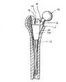
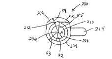
図1および図2は患者の骨髄管12の中に移植可能な大腿骨ステムのような細長いプロテーゼ構成部品10に係合するように構成されたスリーブ100を示している図である。このステム10にはヘッド部またはボール部14が取り付けられており、当該ヘッド部14は自然の股臼またはプロテーゼ股臼構成部品(図示せず)の中に接合する。スリーブ100は一般にテーパー状で環状の本体部102を有しており、当該本体部102は対称形の領域104と大腿骨における軸ずれした基端側の後方の骨の損失部分に対応する補正領域106を備えている。このスリーブ100の補正領域106によって、修復用の大腿骨構成部品が元の大腿骨移植部品の主軸とほぼ同軸に沿って移植することが可能になると共に、基端側の骨の損失部分が補える。このように、修復用のプロテーゼ構成部品を元の移植部品と同軸に移植することによって、元の解剖学的な負荷転移特性が有効に維持できて最適な長期の固定性が得られる。[Embodiment of the Invention]
Hereinafter, the present invention will be described in detail with reference to the accompanying drawings.
FIGS. 1 and 2 illustrate a
一般に、スリーブ本体部102は内孔部(bore)108を有しており、この内孔部は傾斜した内表面部110を画定していて、当該内表面部110が大腿骨構成部品10の傾斜した外表面部に整合する。スリーブ100は大腿骨構成部品10の基端部18に形成したショルダー部16に当接するまで大腿骨ステム10に沿って摺動する。スリーブ100は、機械的結合方法、摩擦係合およびインターロック式の表面形状等を含む種々の技法によって大腿骨ステム10に固定できる。実施形態の一例においては、このスリーブ100は骨の内部成長を促進するための少なくともスリーブ外表面部の一部分を被覆する多孔質コーティングによって固定される。 Generally, the
スリーブ100は本体部102から延出して大腿骨構成部品のショルダー部16に当接するための突出部112を備えている。この突出部分112はスリーブ100の長手軸114に対して鋭角を成している。この突出部分112は大腿骨の距領域(calcar region)20(図1)の中に支持されるように構成されている。 The
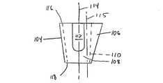
スリーブ本体部102の外表面部は種々の形状に形成して大腿骨における骨の損失部分を補う所望の輪郭に構成できる。上記の対称形領域104および補正領域106は概ね円弧状であって、1個以上の半径によって定められる。なお、対称形領域104はリーム処理を容易にするために概ね対称形としているが、非対称形であってもよい。すなわち、外科医にとって対称形、例えば、円筒形状に骨髄管をリーム処理することが容易だからである。これらの対称形領域104および補正領域106における例示的な形状には、円形、楕円形および長円形等が含まれる。さらに、これらの対称形領域104および補正領域106は概ね傾斜していて、スリーブ100の基端部116はその先端部118よりも大きい。また、補正領域106はスリーブ100の全長あるいはその一部分にわたって延在させることができる。さらに、スリーブの外表面部が周囲の骨に対する固定および骨の内部成長を補助するための任意の適当な表面形状を備え得ることが理解されると考える。 The outer surface portion of the sleeve
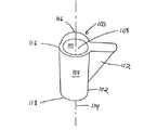
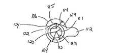
図3乃至図6は図1乃至図2との組み合わせでスリーブ100のさらに詳細な部分を示している図である。底部または先端部118(図3参照)において示すように、内孔部108はスリーブ本体部を貫通している。この内孔部108の内表面部110の先端部118はスリーブ100の長手軸114上に配置される第1の点120から延出する第1の半径R1によって定められる。また、この第1の点120から延出する第2の半径R2はスリーブ外表面部における対称形領域104の先端部を定めている。さらに、スリーブ100の基端部116において長手軸114から延出する第3の半径R3は対称形領域104の基端部を定めている。この対称形領域104はスリーブ100の基端部116から先端部118まで傾斜している。なお、それぞれ長手軸114から延出している第1の複数の半径はスリーブ100の基端部および先端部116,118の間において傾斜した対称形領域104を定めている。すなわち、この場合の第1の複数の半径とは第2の半径R2および第3の半径R3である。 3 to 6 are views showing a more detailed portion of the
一方、スリーブ100の補正領域106は上記第1の点120からずれた第2の点から延出する第4の半径R4によって上部または基端部116において定められる。すなわち、この第2の点は長手軸114からずれている軸115(図6)上に配置されている。また、補正領域106の先端部はスリーブ100の先端部118における軸ずれ軸115から延出する第5の半径R5によって定められる。補正領域106は対称形領域104と同様の態様で基端部116から先端部118にかけて概ねテーパー形状を有していて、これら2個の領域104,106の間の境界部分124を形成している。すなわち、それぞれ軸ずれ軸115から延出する第2の複数の半径が補正領域106を定めていることが分かる。なお、この場合の第2の複数の半径とは第4の半径R4および第5の半径R5である。また、軸ずれ軸115はスリーブの長手軸114に対してほぼ平行か、これに対して若干の角度を成すように構成できる。 On the other hand, the
図7乃至図9はそれぞれの半径の長さによって定められる対称形領域204および補正領域206と共に、長手軸202から延出する複数の半径によって定められる外表面部を有するスリーブ200を示している図である。図7の底面図に示すように、内孔部210の先端部209における内表面部208が第1の半径R1によって定められていて、対称形領域204の先端部が第2の半径R2によって定められている。さらに、第2の半径R2よりも大きな第3の半径R3がスリーブ200の対称形領域204における大きめの基端部211を定めている。この第3の半径R3はスリーブ200の基端部211における長手軸202から延出している。 FIGS. 7-9 illustrate a
第4の半径R4は補正領域206の基端部211を定めており、第5の半径R5は補正領域206の先端部209を定めている。境界部分212はスリーブの外表面部において補正領域206と対称形領域204を分割している。第3の半径R3に比して第4の半径R4において増加された長さ、および第2の半径R2に比して第5の半径R5において増加された長さの組み合わせによってスリーブ外表面部における偏心的形状が構成される。このスリーブ200もまた大腿骨構成部品のショルダー部に当接するための突出部分214を備えている。 The fourth radius R4 defines the
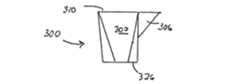
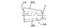
図10乃至図13は本発明に従うスリーブ300のさらに別の実施形態を示している図である。このスリーブ300は対応する軸からそれぞれ延出する複数の半径によって定められる補正領域302を有している。このスリーブ300は突出部分306を備えており、この突出部分306は補正領域302の一部分および対称形領域308の一部分を定めている。図10は補正領域308内に延在する対称形領域308の境界部を点線で示してこれら2個の領域の間の形状の違いを強調している。 FIGS. 10-13 show yet another embodiment of a
図10の底面図に示すように、対称形領域302の基端部310はスリーブ300の長手軸304上の第1の点314から延出する第1の半径312および長手軸304から所定の距離に位置する第2の点318から延出する第2の半径316によって定められている。なお、これらの第1の点314および第2の点318はスリーブの基端部310とほぼ同一平面上にある。実施形態の一例において、第1の点314および第2の点318はスリーブ300を第1部分322aおよび第2の部分322bに分割する第1の平面320上に配置されている。つまり、第1の半径312はスリーブ本体部324に相当する対称形領域308における領域を定めて、第2の半径316はスリーブの突出部分306に相当する対称形領域308における領域を定めている。 As shown in the bottom view of FIG. 10, the
対称形領域308の先端部306はスリーブの先端部における長手軸304から延出する第3の半径328によって定められる。図示のように、スリーブはその基端部310から先端部326にかけて傾斜している。 The
一方、補正領域302の基端部310はスリーブの本体部324によって部分的に形成されて、突出部分306によって部分的に形成されている。さらに、第4の半径329が長手軸304からずれている軸305の上の第3の点330から延出している。この第3の点330はスリーブの基端部310に配置されている。第4の半径329はスリーブ本体部324に相当する補正領域302における基端側領域を定めている。さらに、第5の半径332が第2の点318からずれた第4の点334から延出して、スリーブの突出部分306に相当する補正領域302における領域を定めている。 On the other hand, the
補正領域302の先端部326は、上記突出部分306がスリーブの一部分のみに対応して延在しているので、スリーブ本体部324のみによって構成されている。加えて、第6の半径336がスリーブ先端部326における軸ずれ軸305から延出して、補正領域302の最も先端側の周囲を定めている。 The distal end portion 326 of the
なお、上記の各実施形態における全体の寸法およびそれぞれの半径はスリーブにおける所望の形状に応じて種々変更することができる。例えば、上記第1の点120から第2の点122(図3)に対するずれの距離は約2ミリ乃至約10ミリの間で変えることができる。また、上記半径の長さは例えば視覚的および/またはX線画像処理技法によって決定しながら骨の損失部分を補うために変更できる。さらに、上記第4の半径は約5ミリ乃至約12ミリの範囲の例示的な長さを有し、第5の半径は約3ミリ乃至約12ミリの範囲の長さを有する。一般に、軸ずれの距離が大きくなると、スリーブ外表面部における補正領域を定める半径の長さが逆比例に小さくなる。 It should be noted that the overall dimensions and the respective radii in the above embodiments can be variously changed according to the desired shape of the sleeve. For example, the displacement distance from the
本明細書に記載した実施形態に鑑みて、当該技術分野における熟練者であれば、上記スリーブを定める各半径の長さならびに当該半径が延出する各点を単一または組み合わせにおいて変更してスリーブの外表面部における特定の形状を構成することが容易に可能である。 In view of the embodiments described herein, those skilled in the art can change the length of each radius defining the sleeve and the points where the radius extends in a single or combination to change the sleeve. It is possible to easily form a specific shape in the outer surface portion of the.
従って、上記スリーブは元の大腿骨構成部品が患者の大腿骨に移植されている間に生じる基端側で後方側の骨の損失を補うために修復用大腿骨構成部品と共に使用するのに適している。 Thus, the sleeve is suitable for use with a repair femoral component to compensate for proximal and posterior bone loss that occurs while the original femoral component is implanted in the patient's femur. ing.
骨の損失を補うための本発明に従うスリーブの例示的な使用方法において、外科医はまず当該技術分野における通常の熟練者に周知の方法を用いて元のプロテーゼ構成部品を取り外す。その後、骨髄管をリーム処理して修復用の大腿骨構成部品を受容できるように準備する。一般に、骨髄管の寸法は骨セメント材および骨の内部成長部分を除去するために拡大する必要がある。従来的なスリーブ構成部品を使用するのに対して、本明細書に記載する大腿骨構成部品/スリーブ組立体は主軸に沿って移植される。すなわち、骨髄管が主軸または元の移植部品の長手軸と同軸に必要なだけリーム処理され、これらの軸は一般に骨の長手軸に対応している。このことは骨の負荷がこの軸に沿って転移するために好都合である。一方、移植部品が上記の主軸からずれていると、負荷によって移植部品が捩れやすくなり、これによって、骨の中の移植部品の長期固定の可能性が低減する。 In an exemplary method of using a sleeve according to the present invention to compensate for bone loss, the surgeon first removes the original prosthetic component using methods well known to those of ordinary skill in the art. The medullary canal is then reamed and prepared to receive a repair femoral component. In general, the size of the medullary canal needs to be increased to remove bone cement material and bone ingrowth. Whereas conventional sleeve components are used, the femoral component / sleeve assembly described herein is implanted along the main axis. That is, the medullary canal is reamed as needed coaxially with the main axis or the longitudinal axis of the original implant, and these axes generally correspond to the longitudinal axis of the bone. This is advantageous because the bone load is transferred along this axis. On the other hand, if the implant is displaced from the main axis, the implant is easily twisted by the load, thereby reducing the possibility of long-term fixation of the implant in the bone.
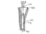
図14乃至図17は本発明に従う大腿骨構成部品/スリーブ組立体を受容するために骨に空孔部を形成するための例示的な技法および装置を示している図である。まず、元の大腿骨構成部品(図示せず)を取り外して骨の骨髄管400を露出させる(図14)。骨髄管の後方側/基端側の領域402に骨の損失部分が示されている。次に、円筒形のリーマー405を有する従来的なリーム処理装置404(図15)を用いて修復用大腿骨ステムの移植のために骨の長手軸または主軸406に沿って骨髄管400をリーム処理する。図示のように、この従来的なリーマー405は骨髄管の後方側/基端側の領域402の中の骨を除去しない。次に、円錐台形状のリーマー407を用いて骨髄管400の基端側領域における主軸406の周りに対称形の空孔部を形成する。その後、大腿骨の距領域20(図1)をリーム処理してステム10のショルダー部16に当接するスリーブ100(図1)の突出部112を支持できるようにする。スリーブの突出部12に対応する空孔部は本明細書に参考文献として含まれるNoilesに付与された米国特許第4,790,852号に図示および記載されているようにしてリーム処理できる。 FIGS. 14-17 illustrate an exemplary technique and apparatus for forming a hole in a bone to receive a femoral component / sleeve assembly in accordance with the present invention. First, the original femoral component (not shown) is removed to expose the bone marrow canal 400 (FIG. 14). Bone loss is shown in the posterior /
骨髄管の基端側領域402はスリーブ100の外表面部と一致するようにリーム処理する必要がある(図1乃至図2)。すなわち、骨髄管400はスリーブの偏心的な外表面部すなわち補正領域106を支持するようにリーム処理される必要がある。この場合、例えば、三角形および/または円錐形状のリーマーを用いて骨髄管の必要な偏心リーム処理を行なうことができる。実施形態の一例においては、円錐台形状のリーマー408(図17)が骨髄管400の中に挿入した円筒形のガイド412によって軸ずれ軸410に位置合わせされている。この位置合わせ処理によって、骨髄管の基端側/後方側領域をリーム処理することができ、これによって、当該領域がスリーブ102の外表面部における上記対称形領域104および補正領域106(図2)に整合する。 The
当該技術分野における熟練者であれば、上記の実施形態に基づいて本発明のさらに別の特徴および利点を見出すことが可能である。従って、本発明は本明細書において特に図示しかつ説明したものによって制限されるものではなく、特許請求の範囲ならびにその実施態様によってのみ制限されると解するべきである。なお、本明細書に引用した全ての公表物および文献はそれらの全体が本明細書に参考文献として含まれる。 Those skilled in the art can find further features and advantages of the present invention based on the above-described embodiments. Accordingly, it is to be understood that the invention is not limited by what has been particularly shown and described herein, but only by the claims and the embodiments thereof. It should be noted that all publications and references cited herein are hereby incorporated by reference in their entirety.
本発明の実施態様は以下の通りである。
(I)患者の骨髄管の中に移植可能なプロテーゼ構成部品に係合するためのスリーブにおいて、
前記プロテーゼ構成部品が挿入可能な貫通した内孔部を有する細長い本体部から成り、当該本体部が骨の損失部分を補うための補正領域と対称形領域とを有する偏心した外表面部を備えていることを特徴とするスリーブ。
(1)前記対称形領域が第1の点から延出する第1の複数の半径によって定められる実施態様(I)に記載のスリーブ。
(2)前記補正領域が第2の点から延出する第2の複数の半径によって定められる実施態様(1)に記載のスリーブ。
(3)前記第2の点が前記第1の点からずれている実施態様(2)に記載のスリーブ。
(4)前記第1の点が前記スリーブの長手軸の上に配置されている実施態様(3)に記載のスリーブ。
(5)前記スリーブが前記プロテーゼ構成部品のショルダー部に当接するための突出領域を備えている実施態様(I)に記載のスリーブ。Embodiments of the present invention are as follows.
(I) in a sleeve for engaging a prosthetic component implantable in a patient's medullary canal;
The prosthesis component comprises an elongate body having an insertable through bore, the body having an eccentric outer surface having a correction area and a symmetrical area to compensate for the loss of bone. A sleeve characterized by being.
(1) The sleeve according to embodiment (I), wherein the symmetrical region is defined by a first plurality of radii extending from a first point.
(2) The sleeve according to the embodiment (1), wherein the correction region is defined by a second plurality of radii extending from the second point.
(3) The sleeve according to the embodiment (2), wherein the second point is deviated from the first point.
(4) The sleeve according to the embodiment (3), wherein the first point is disposed on a longitudinal axis of the sleeve.
(5) The sleeve according to the embodiment (I), wherein the sleeve includes a protruding region for abutting against a shoulder portion of the prosthesis component.
(6)前記本体部が傾斜している実施態様(I)に記載のスリーブ。
(7)前記第1の点が前記第2の点に位置合わせされている実施態様(2)に記載のスリーブ。
(8)前記第1の複数の半径における第1のものがこれに対応する前記第2の複数の半径における第1のものに比して小さい実施態様(7)に記載のスリーブ。
(9)前記補正領域が前記スリーブの全長にわたって延在している実施態様(I)に記載のスリーブ。
(II)大腿骨構成部品の基端部に連結するためのスリーブにおいて、
長手軸と、第1の端部および第2の端部と、これらを貫通する内孔部とを有する本体部から成り、当該本体部が患者の大腿骨における基端側で後方側の骨の損失部分を補うための補正領域と対称形領域とを有する偏心した外表面部を備えており、当該対称形領域が前記長手軸から延出する第1の複数の半径によって定められ、補正領域が前記長手軸からずれている軸から延出する第2の複数の半径によって定められていることを特徴とするスリーブ。
(10)前記長手軸と前記軸ずれ軸との間のずれが約2ミリ乃至約10ミリの範囲内である実施態様(II)に記載のスリーブ。(6) The sleeve according to the embodiment (I), in which the main body portion is inclined.
(7) The sleeve according to the embodiment (2), wherein the first point is aligned with the second point.
(8) The sleeve according to the embodiment (7), wherein the first one in the first plurality of radii is smaller than the first one in the second plurality of radii corresponding thereto.
(9) The sleeve according to the embodiment (I), wherein the correction region extends over the entire length of the sleeve.
(II) In a sleeve for connecting to the proximal end of the femoral component,
A body portion having a longitudinal axis, a first end portion and a second end portion, and an inner hole portion extending therethrough, the body portion being proximal to the patient's femur, An eccentric outer surface having a correction region to compensate for the loss portion and a symmetric region, the symmetric region being defined by a first plurality of radii extending from the longitudinal axis, wherein the correction region is A sleeve defined by a second plurality of radii extending from an axis that is offset from the longitudinal axis.
(10) The sleeve of embodiment (II), wherein the deviation between the longitudinal axis and the off-axis axis is in the range of about 2 mm to about 10 mm.
(11)前記本体部が傾斜している実施態様(II)に記載のスリーブ。
(12)前記本体部が前記補正領域において異なる厚さを有している実施態様(II)に記載のスリーブ。
(III)大腿骨構成部品の基端部に連結するためのスリーブにおいて、
長手軸と、第1の端部および第2の端部と、これらを貫通する内孔部とを有する本体部から成り、当該本体部が患者の大腿骨における基端側で後方側の骨の損失部分を補うための補正領域と対称形領域とを有する偏心した外表面部を備えており、当該対称形領域が前記長手軸の上に位置する第1の点から延出する第1の複数の半径によって定められ、補正領域が前記長手軸から延出する第2の複数の半径によって定められており、当該第1の複数の半径における第1のものがこれに対応する第2の複数の半径における第1のものよりも短くて、前記本体部の第1の端部において、前記補正領域の厚さが前記対称形領域の厚さよりも厚いことを特徴とするスリーブ。
(13)前記スリーブが傾斜している実施態様(III)に記載のスリーブ。
(14)前記補正領域が前記スリーブの全長にわたって延在している実施態様(III)に記載のスリーブ。
(IV)大腿骨ステムに連結するためのスリーブにおいて、
突出部と長手軸を有する概ね円筒形の本体部から成り、当該突出部が本体部から延出しており、当該本体部が対称形領域と患者の大腿骨の基端側で後方側における骨の損失を補うための補正領域とによって形成される偏心した外表面部を有しており、当該補正領域が円筒形の本体部に対応する第1の部分と前記突出部に対応する第2の部分を有していることを特徴とするスリーブ。
(15)前記補正領域の第1の部分が、前記長手軸からずれている第1の軸から延出する半径によって定められている実施態様(IV)に記載のスリーブ。
(16)前記補正領域の第2の部分が、前記長手軸からずれている第2の軸から延出する半径によって定められている実施態様(15)に記載のスリーブ。(11) The sleeve according to the embodiment (II), in which the main body portion is inclined.
(12) The sleeve according to the embodiment (II), wherein the main body has different thicknesses in the correction region.
(III) In a sleeve for connecting to the proximal end of the femoral component,
A body portion having a longitudinal axis, a first end portion and a second end portion, and an inner hole portion extending therethrough, the body portion being proximal to the patient's femur, A first plurality of eccentric outer surface portions having a correction region and a symmetric region for compensating for the loss portion, wherein the symmetric region extends from a first point located on the longitudinal axis; And the correction region is defined by a second plurality of radii extending from the longitudinal axis, the first of the first plurality of radii corresponding to the second plurality of radii. A sleeve that is shorter than the first one in radius and wherein the thickness of the correction region is greater than the thickness of the symmetric region at the first end of the body portion.
(13) The sleeve according to the embodiment (III), in which the sleeve is inclined.
(14) The sleeve according to the embodiment (III), wherein the correction region extends over the entire length of the sleeve.
(IV) In a sleeve for connection to a femoral stem,
Consists of a generally cylindrical body having a protrusion and a longitudinal axis, the protrusion extending from the body, the body being symmetrical and the proximal side of the patient's femur A first portion corresponding to the cylindrical main body portion and a second portion corresponding to the protruding portion, the outer surface portion having an eccentricity formed by the correction region for compensating for the loss. The sleeve characterized by having.
(15) The sleeve according to the embodiment (IV), wherein the first portion of the correction region is defined by a radius extending from the first axis that is offset from the longitudinal axis.
(16) The sleeve according to embodiment (15), wherein the second portion of the correction region is defined by a radius extending from a second axis that is offset from the longitudinal axis.
[発明の効果]
従って、本発明によれば、移植後に修復用プロテーゼ構成部品の長手軸が主軸(元のプロテーゼ構成部品または移植した骨の長手軸)に一致するように修復用プロテーゼ構成部品と共に使用する骨の損失部分を補うためのスリーブを受容するように骨髄管をリーム処理するためのリーム装置が提供される。[The invention's effect]
Thus, according to the present invention, bone loss for use with a repair prosthesis component so that the longitudinal axis of the repair prosthesis component after implantation is aligned with the main axis (original prosthesis component or the longitudinal axis of the implanted bone). A reaming device is provided for reaming the medullary canal to receive a sleeve to supplement the portion.
10 ステム
12 骨髄管
100 スリーブ
104 対称形領域
106 補正領域10
Claims (1)
Translated fromJapanese基端部および先端部を有する回転部材から成り、当該回転部材が骨の長手軸からずれた軸ずれ軸の回りに回転可能であり、さらに、
前記回転部材に連結して前記軸ずれ軸の回りに回転可能な円錐台形状の外表面部を有するリーマーと、
骨の長手軸に位置合わせされた状態で、前記骨髄管内に挿入されるガイド部材と、を含み、
前記リーマーが骨の損失を補うための補正領域と対称形領域を有する偏心した外表面部を有する傾斜したスリーブ構成部品の外表面部に接合するための偏心した空孔部を形成することを特徴とするリーム装置。In a reaming device for reaming an eccentric cavity in a bone marrow canal of a bone having a longitudinal axis,
A rotating member having a proximal end and a distal end, the rotating member being rotatable about an off-axis axis that is offset from the longitudinal axis of the bone;
A reamer having a frustoconical outer surface connected to the rotating member and rotatable about the off-axis axis;
A guide member inserted into the medullary canal in a state aligned with the longitudinal axis of the bone,
The reamer forms an eccentric cavity for joining to an outer surface of an inclined sleeve component having an eccentric outer surface having a correction region and a symmetrical region to compensate for bone loss. Ream device.
Applications Claiming Priority (1)
| Application Number | Priority Date | Filing Date | Title |
|---|---|---|---|
| US09/219,583US6139584A (en) | 1998-12-22 | 1998-12-22 | Proximal femoral sleeve for a revision hip prosthesis |
Related Parent Applications (1)
| Application Number | Title | Priority Date | Filing Date |
|---|---|---|---|
| JP36326899ADivisionJP4090652B2 (en) | 1998-12-22 | 1999-12-21 | Proximal femoral sleeve for lumbar prosthesis for repair |
Publications (1)
| Publication Number | Publication Date |
|---|---|
| JP2008119492Atrue JP2008119492A (en) | 2008-05-29 |
Family
ID=22819870
Family Applications (2)
| Application Number | Title | Priority Date | Filing Date |
|---|---|---|---|
| JP36326899AExpired - Fee RelatedJP4090652B2 (en) | 1998-12-22 | 1999-12-21 | Proximal femoral sleeve for lumbar prosthesis for repair |
| JP2007336368APendingJP2008119492A (en) | 1998-12-22 | 2007-12-27 | Reaming device |
Family Applications Before (1)
| Application Number | Title | Priority Date | Filing Date |
|---|---|---|---|
| JP36326899AExpired - Fee RelatedJP4090652B2 (en) | 1998-12-22 | 1999-12-21 | Proximal femoral sleeve for lumbar prosthesis for repair |
Country Status (5)
| Country | Link |
|---|---|
| US (1) | US6139584A (en) |
| EP (2) | EP1238635B1 (en) |
| JP (2) | JP4090652B2 (en) |
| AU (1) | AU769625B2 (en) |
| DE (2) | DE69935399T2 (en) |
Families Citing this family (60)
| Publication number | Priority date | Publication date | Assignee | Title |
|---|---|---|---|---|
| KR100358192B1 (en)* | 2000-02-16 | 2002-10-25 | 한국과학기술원 | Jacket for cementless artificial joint and the artificial joint with it |
| KR100358193B1 (en)* | 2000-02-16 | 2002-10-25 | 한국과학기술원 | Plastic jacket for cementless artificial joint and the artificial joint with it |
| WO2002007653A1 (en)* | 2000-07-20 | 2002-01-31 | Depuy Orthopaedics, Inc. | Modular femoral stem component for a hip joint prosthesis |
| US7497874B1 (en) | 2001-02-23 | 2009-03-03 | Biomet Manufacturing Corp. | Knee joint prosthesis |
| US20020120340A1 (en) | 2001-02-23 | 2002-08-29 | Metzger Robert G. | Knee joint prosthesis |
| AU2002245702A1 (en) | 2001-03-19 | 2002-10-03 | Cambridge Polymer Group Inc. | System and methods for reducing interfacial porosity in cements |
| US7892288B2 (en) | 2001-08-27 | 2011-02-22 | Zimmer Technology, Inc. | Femoral augments for use with knee joint prosthesis |
| US20040162619A1 (en) | 2001-08-27 | 2004-08-19 | Zimmer Technology, Inc. | Tibial augments for use with knee joint prostheses, method of implanting the tibial augment, and associated tools |
| US20030065397A1 (en) | 2001-08-27 | 2003-04-03 | Hanssen Arlen D. | Prosthetic implant support structure |
| US6902583B2 (en) | 2002-04-25 | 2005-06-07 | Medicinelodge, Inc. | Tripartite attachment mechanism and method for a modular prosthesis |
| US6875239B2 (en)* | 2002-04-25 | 2005-04-05 | Medicinelodge, Inc. | Modular prosthesis for replacing bone and method |
| US7182786B2 (en) | 2002-04-25 | 2007-02-27 | Zimmer Technology, Inc. | Modular bone implant, tool, and method |
| USD684693S1 (en) | 2002-08-22 | 2013-06-18 | Zimmer, Inc. | Prosthetic implant support structure |
| US20040049285A1 (en)* | 2002-09-09 | 2004-03-11 | Brian Haas | Duo-fixation prosthetic joints |
| JP3779674B2 (en)* | 2002-11-18 | 2006-05-31 | 泉工医科工業株式会社 | Distal tip for stem positioning of artificial joints |
| US6887276B2 (en) | 2002-12-13 | 2005-05-03 | Medicine Lodge, Inc | Modular implant for joint reconstruction and method of use |
| US6866683B2 (en) | 2002-12-13 | 2005-03-15 | Medicine Lodge, Inc. | Modular implant for joint reconstruction and method of use |
| GB0305449D0 (en) | 2003-03-10 | 2003-04-16 | Benoist Girard Sas | Femoral prosthesis |
| US20040254646A1 (en)* | 2003-06-16 | 2004-12-16 | Stone Kevin T. | Provisional coupling mechanism |
| US8998919B2 (en) | 2003-06-25 | 2015-04-07 | DePuy Synthes Products, LLC | Assembly tool for modular implants, kit and associated method |
| US7582092B2 (en) | 2003-06-25 | 2009-09-01 | Depuy Products, Inc. | Assembly tool for modular implants and associated method |
| US7892290B2 (en)* | 2004-05-28 | 2011-02-22 | Smith & Nephew, Inc. | Fluted sleeve hip prosthesis for modular stem |
| AU2005249515B2 (en)* | 2004-05-28 | 2011-11-10 | Smith & Nephew, Inc. | Fluted intramedullary stem |
| WO2006065880A2 (en)* | 2004-12-17 | 2006-06-22 | Depuy Products, Inc. | Modular implant system and method with diaphyseal implant and adapter |
| US7998217B1 (en) | 2005-02-02 | 2011-08-16 | Biomet Manufacturing Corp. | Modular offset stem implants |
| GB0517945D0 (en)* | 2005-09-03 | 2005-10-12 | Depuy Int Ltd | An orthopaedic joint prosthesis implant kit |
| US7842093B2 (en) | 2006-07-18 | 2010-11-30 | Biomet Manufacturing Corp. | Method and apparatus for a knee implant |
| US8597298B2 (en) | 2006-09-29 | 2013-12-03 | DePuy Synthes Products, LLC | Proximal reamer |
| US8187280B2 (en) | 2007-10-10 | 2012-05-29 | Biomet Manufacturing Corp. | Knee joint prosthesis system and method for implantation |
| US8163028B2 (en) | 2007-01-10 | 2012-04-24 | Biomet Manufacturing Corp. | Knee joint prosthesis system and method for implantation |
| US8328873B2 (en) | 2007-01-10 | 2012-12-11 | Biomet Manufacturing Corp. | Knee joint prosthesis system and method for implantation |
| JP5448842B2 (en) | 2007-01-10 | 2014-03-19 | バイオメト マニファクチャリング コーポレイション | Knee joint prosthesis system and implantation method |
| US8562616B2 (en) | 2007-10-10 | 2013-10-22 | Biomet Manufacturing, Llc | Knee joint prosthesis system and method for implantation |
| WO2009046121A2 (en)* | 2007-10-01 | 2009-04-09 | Smith & Nephew, Inc. | Method and apparatus for preparing bone for a prosthetic device |
| US8556912B2 (en) | 2007-10-30 | 2013-10-15 | DePuy Synthes Products, LLC | Taper disengagement tool |
| US8518050B2 (en) | 2007-10-31 | 2013-08-27 | DePuy Synthes Products, LLC | Modular taper assembly device |
| US8167882B2 (en) | 2008-09-30 | 2012-05-01 | Depuy Products, Inc. | Minimally invasive bone miller apparatus |
| US8123815B2 (en) | 2008-11-24 | 2012-02-28 | Biomet Manufacturing Corp. | Multiple bearing acetabular prosthesis |
| US8308810B2 (en) | 2009-07-14 | 2012-11-13 | Biomet Manufacturing Corp. | Multiple bearing acetabular prosthesis |
| US8533921B2 (en) | 2010-06-15 | 2013-09-17 | DePuy Synthes Products, LLC | Spiral assembly tool |
| US9095452B2 (en) | 2010-09-01 | 2015-08-04 | DePuy Synthes Products, Inc. | Disassembly tool |
| ES2635496T3 (en) | 2011-04-06 | 2017-10-04 | Depuy Synthes Products Llc | Modular Orthopedic Hip Prosthesis |
| US8900317B2 (en) | 2011-05-20 | 2014-12-02 | Zimmer, Inc. | Stabilizing prosthesis support structure |
| EP2787901B1 (en) | 2011-12-09 | 2017-06-07 | Howmedica Osteonics Corp. | Surgical reaming instrument for shaping a bone cavity |
| WO2013102089A1 (en) | 2011-12-30 | 2013-07-04 | Howmedica Osteonics Corp. | Systems for preparing bone voids to receive a prosthesis |
| US8961612B2 (en) | 2012-08-30 | 2015-02-24 | Biomet Manufacturing, Llc | Knee component having orbital interface boss |
| US9949839B2 (en)* | 2013-03-13 | 2018-04-24 | Wright Medical Technology, Inc. | Revision implant augments, systems, and methods |
| US9526513B2 (en) | 2013-03-13 | 2016-12-27 | Howmedica Osteonics Corp. | Void filling joint prosthesis and associated instruments |
| US10149763B2 (en) | 2015-01-12 | 2018-12-11 | Howmedica Osteonics Corp. | Multipurpose void filling prosthesis |
| US10136998B2 (en) | 2016-08-30 | 2018-11-27 | Wright Medical Technology, Inc. | Revision total ankle implants |
| CA3051099C (en) | 2017-01-20 | 2022-07-12 | Biomet Manufacturing, Llc | Modular augment component |
| CN107157626A (en)* | 2017-07-18 | 2017-09-15 | 优适医疗科技(苏州)有限公司 | Distal femoral component prosthese |
| US11565021B1 (en) | 2019-08-12 | 2023-01-31 | Ortho Development Corporation | Composite structure porous implant for replacing bone stock |
| USD901013S1 (en) | 2019-08-12 | 2020-11-03 | Ortho Development Corporation | Porous implant |
| USD901012S1 (en) | 2019-08-12 | 2020-11-03 | Ortho Development Corporation | Porous implant |
| USD901014S1 (en) | 2019-08-12 | 2020-11-03 | Ortho Development Corporation | Porous implant |
| US12434302B2 (en) | 2019-11-25 | 2025-10-07 | Ortho Development Corporation | Method for manufacturing porous structures using additive manufacturing |
| US11498124B1 (en) | 2019-11-25 | 2022-11-15 | Ortho Development Corporation | Method for sintering porous structures from powder using additive manufacturing |
| US12115084B2 (en) | 2021-12-21 | 2024-10-15 | Depuy Ireland Unlimited Company | Method of installing a knee cone augment in an orthopaedic surgical procedure |
| USD1090843S1 (en)* | 2023-10-13 | 2025-08-26 | Hefei Longshore Tech Co., Ltd | Femoral stem and neck prosthesis assembly |
Citations (2)
| Publication number | Priority date | Publication date | Assignee | Title |
|---|---|---|---|---|
| US5527316A (en)* | 1994-02-23 | 1996-06-18 | Stone; Kevin T. | Surgical reamer |
| EP0782842A2 (en)* | 1996-01-04 | 1997-07-09 | Joint Medical Products Corporation | Method and apparatus for fitting a prosthesis to a bone |
Family Cites Families (10)
| Publication number | Priority date | Publication date | Assignee | Title |
|---|---|---|---|---|
| DE2356464A1 (en)* | 1973-11-12 | 1975-05-22 | Rosenthal Technik Ag | SIMPLE FEMORAL HEAD DROSTHESIS AND DRILLING DEVICE FOR ITS FIXING |
| EP0172883A1 (en)* | 1984-02-09 | 1986-03-05 | JOINT MEDICAL PRODUCTS CORPORATION (a Delaware corporation) | Apparatus for affixing a prosthesis to bone |
| US4790852A (en)* | 1986-09-15 | 1988-12-13 | Joint Medical Products Corporation | Sleeves for affixing artificial joints to bone |
| US5658349A (en)* | 1991-07-29 | 1997-08-19 | Joint Medical Products Corporation | Prosthetic joint system for bone replacement |
| US5908423A (en)* | 1993-05-27 | 1999-06-01 | Howmedica, Inc. | Flexible medullary reaming system |
| DE4325714A1 (en)* | 1993-07-30 | 1995-02-02 | Schmidt Ramsin Eckhard Dr Med | Hip prosthesis |
| US5858020A (en)* | 1995-12-05 | 1999-01-12 | Metagen, Llc | Modular prosthesis |
| WO1998006359A1 (en)* | 1996-08-13 | 1998-02-19 | Grimes James B | Femoral head-neck prosthesis and method of implantation |
| WO1998008467A1 (en)* | 1996-08-30 | 1998-03-05 | Hunter Innovations, Inc. | Adjustable modular orthopedic implant |
| US5906644A (en)* | 1996-08-30 | 1999-05-25 | Powell; Douglas Hunter | Adjustable modular orthopedic implant |
- 1998
- 1998-12-22USUS09/219,583patent/US6139584A/ennot_activeExpired - Fee Related
- 1999
- 1999-12-20AUAU65359/99Apatent/AU769625B2/ennot_activeCeased
- 1999-12-21DEDE69935399Tpatent/DE69935399T2/ennot_activeExpired - Lifetime
- 1999-12-21EPEP02076489Apatent/EP1238635B1/ennot_activeExpired - Lifetime
- 1999-12-21DEDE69941271Tpatent/DE69941271D1/ennot_activeExpired - Lifetime
- 1999-12-21EPEP99310355Apatent/EP1013241B1/ennot_activeExpired - Lifetime
- 1999-12-21JPJP36326899Apatent/JP4090652B2/ennot_activeExpired - Fee Related
- 2007
- 2007-12-27JPJP2007336368Apatent/JP2008119492A/enactivePending
Patent Citations (3)
| Publication number | Priority date | Publication date | Assignee | Title |
|---|---|---|---|---|
| US5527316A (en)* | 1994-02-23 | 1996-06-18 | Stone; Kevin T. | Surgical reamer |
| EP0782842A2 (en)* | 1996-01-04 | 1997-07-09 | Joint Medical Products Corporation | Method and apparatus for fitting a prosthesis to a bone |
| JPH09294755A (en)* | 1996-01-04 | 1997-11-18 | Joint Medical Prod Corp | Prosthesis for transplantation to bone and transplantation method |
Also Published As
| Publication number | Publication date |
|---|---|
| EP1013241A2 (en) | 2000-06-28 |
| EP1013241B1 (en) | 2007-03-07 |
| AU6535999A (en) | 2000-06-29 |
| DE69941271D1 (en) | 2009-09-24 |
| AU769625B2 (en) | 2004-01-29 |
| JP2000210314A (en) | 2000-08-02 |
| DE69935399T2 (en) | 2007-11-15 |
| JP4090652B2 (en) | 2008-05-28 |
| US6139584A (en) | 2000-10-31 |
| DE69935399D1 (en) | 2007-04-19 |
| EP1238635A2 (en) | 2002-09-11 |
| EP1238635B1 (en) | 2009-08-12 |
| EP1013241A3 (en) | 2002-03-06 |
| EP1238635A3 (en) | 2004-01-02 |
Similar Documents
| Publication | Publication Date | Title |
|---|---|---|
| JP4090652B2 (en) | Proximal femoral sleeve for lumbar prosthesis for repair | |
| JP4201960B2 (en) | Prosthesis system | |
| AU784624B2 (en) | Hip implant assembly | |
| US6755866B2 (en) | Prosthetic stem with bearings | |
| AU2006216763B2 (en) | Long sleeves for use with stems | |
| JP4838731B2 (en) | Femoral hip prosthesis and transplantation method | |
| US6508840B1 (en) | Collarless shoulder arthroplasty prosthesis | |
| US6284002B1 (en) | Proximal femoral replacement implant and method of implanting the same | |
| US5725595A (en) | Cannulated cementless hip stem prosthesis | |
| US20030074080A1 (en) | Modular neck for femur replacement surgery | |
| US20100114323A1 (en) | Knee prosthesis kit with winged sleeves and milling guide | |
| JP4659044B2 (en) | Modular shaft and collar implant | |
| US7494509B1 (en) | Method and apparatus for providing a short-stemmed hip prosthesis | |
| JP4608497B2 (en) | Tapered joint prosthesis | |
| WO2012075183A2 (en) | Stem for use in joint arthroplasty | |
| JP4397597B2 (en) | Cement plug method | |
| US12263088B2 (en) | Expandable hip stem | |
| AU2017370359B2 (en) | Revision prosthesis shaft for a revision joint endoprosthesis | |
| JP2023104926A (en) | Reinforcement element for knee prosthesis |
Legal Events
| Date | Code | Title | Description |
|---|---|---|---|
| A131 | Notification of reasons for refusal | Free format text:JAPANESE INTERMEDIATE CODE: A131 Effective date:20100601 | |
| A977 | Report on retrieval | Free format text:JAPANESE INTERMEDIATE CODE: A971007 Effective date:20100603 | |
| A521 | Request for written amendment filed | Free format text:JAPANESE INTERMEDIATE CODE: A523 Effective date:20100827 | |
| A131 | Notification of reasons for refusal | Free format text:JAPANESE INTERMEDIATE CODE: A131 Effective date:20100928 | |
| A521 | Request for written amendment filed | Free format text:JAPANESE INTERMEDIATE CODE: A523 Effective date:20101228 | |
| A02 | Decision of refusal | Free format text:JAPANESE INTERMEDIATE CODE: A02 Effective date:20110201 | |
| A521 | Request for written amendment filed | Free format text:JAPANESE INTERMEDIATE CODE: A523 Effective date:20110525 | |
| A521 | Request for written amendment filed | Free format text:JAPANESE INTERMEDIATE CODE: A523 Effective date:20110622 | |
| A911 | Transfer to examiner for re-examination before appeal (zenchi) | Free format text:JAPANESE INTERMEDIATE CODE: A911 Effective date:20110713 | |
| A912 | Re-examination (zenchi) completed and case transferred to appeal board | Free format text:JAPANESE INTERMEDIATE CODE: A912 Effective date:20110819 |