JP2008117102A - Shopping cart - Google Patents
Shopping cartDownload PDFInfo
- Publication number
- JP2008117102A JP2008117102AJP2006298490AJP2006298490AJP2008117102AJP 2008117102 AJP2008117102 AJP 2008117102AJP 2006298490 AJP2006298490 AJP 2006298490AJP 2006298490 AJP2006298490 AJP 2006298490AJP 2008117102 AJP2008117102 AJP 2008117102A
- Authority
- JP
- Japan
- Prior art keywords
- cart
- shopping cart
- information processing
- writer
- lock
- Prior art date
- Legal status (The legal status is an assumption and is not a legal conclusion. Google has not performed a legal analysis and makes no representation as to the accuracy of the status listed.)
- Granted
Links
Images


Classifications
- B—PERFORMING OPERATIONS; TRANSPORTING
- B62—LAND VEHICLES FOR TRAVELLING OTHERWISE THAN ON RAILS
- B62B—HAND-PROPELLED VEHICLES, e.g. HAND CARTS OR PERAMBULATORS; SLEDGES
- B62B5/00—Accessories or details specially adapted for hand carts
- B62B5/0096—Identification of the cart or merchandise, e.g. by barcodes or radio frequency identification [RFID]
Landscapes
- Management, Administration, Business Operations System, And Electronic Commerce (AREA)
- Financial Or Insurance-Related Operations Such As Payment And Settlement (AREA)
- Handcart (AREA)
- Coin-Freed Apparatuses For Hiring Articles (AREA)
Abstract
Description
Translated fromJapanese本発明は、スーパーマーケット等の店舗で使用されるショッピングカートに関する。 The present invention relates to a shopping cart used in a store such as a supermarket.
最近のショッピングカートは、情報処理機能を有するものがある。一例として、LCD等の表示部を備え、この表示部に広告情報等の各種情報を情報処理機能によって表示させるようにしたショッピングカートが知られている(例えば、特許文献1参照)。これによれば、買物時の利便性が向上するため、この利便性を求めて来店する顧客の増加による売上増を期待することができる。 Some recent shopping carts have an information processing function. As an example, a shopping cart that includes a display unit such as an LCD and displays various information such as advertisement information on the display unit by an information processing function is known (for example, see Patent Document 1). According to this, since convenience at the time of shopping is improved, it is possible to expect an increase in sales due to an increase in the number of customers who visit the store for this convenience.
ところで、ショッピングカートは、使用後に店舗に返却されずに紛失してしまう場合がある。そして、情報処理機能を有するショッピングカートについては、一般的なショッピングカートよりも高価であるため、返却されないことによる紛失の代償はより大きい。そのため、情報処理機能を有するショッピングカートについては、紛失した場合の代償の大きさの問題から、集客効果を期待するものの導入に踏み切れない店舗が多く存在し、広範な普及に至っていないのが現状である。 By the way, the shopping cart may be lost without being returned to the store after use. And since the shopping cart which has an information processing function is more expensive than a general shopping cart, the price of the loss by not returning is larger. For shopping carts that have information processing functions, therefore, there are many stores that are unable to introduce customers who expect the effect of attracting customers due to the problem of the price of lost items, and have not yet been widely spread. is there.
本発明の目的は、情報処理機能を有するショッピングカートの紛失を防止することである。 An object of the present invention is to prevent a shopping cart having an information processing function from being lost.
本発明のショッピングカートは、商品を収納して移動自在なカート本体と、情報処理機能を果たす情報処理部と、前記カート本体の移動を解除自在にロックするロック部と、アンテナを有し当該アンテナの通信可能範囲に位置付けられた電子マネー媒体が有する電子マネーを記憶するRFIDチップとの間で当該アンテナを介して通信を実行するRFIDリーダライタと、前記ロック部により前記カート本体の移動がロックされている状態で、前記情報処理機能を用いて、前記RFIDリーダライタを介して前記RFIDチップに記憶された電子マネーからデポジット金額分の電子マネーを引き落とし、前記引き落としを条件として、前記情報処理機能を用いて、前記ロック部にロックを解除させ、また、前記情報処理機能を用いて、前記ロック部に前記カート本体の移動をロックさせ、前記ロック部により前記カート本体の移動がロックされたならば、前記情報処理機能を用いて、前記RFIDリーダライタを介して前記引き落としたデポジット金額分の電子マネーを前記RFIDチップに払い戻すようにした。 The shopping cart of the present invention has a cart main body storing and moving goods, an information processing section for performing an information processing function, a lock section for releasably locking the movement of the cart main body, and an antenna. The movement of the cart body is locked by the RFID reader / writer that performs communication via the antenna with the RFID chip that stores the electronic money included in the electronic money medium positioned in the communicable range, and the lock unit. With the information processing function, the electronic money corresponding to the deposit amount is withdrawn from the electronic money stored in the RFID chip via the RFID reader / writer, and the information processing function is The lock unit is used to release the lock, and the information processing function is used to If the movement of the cart body is locked by the lock section and the movement of the cart body is locked by the lock section, the amount of deposit amount withdrawn via the RFID reader / writer is used using the information processing function. Electronic money was paid back to the RFID chip.
本発明によれば、ロック部によるロックを解除してショッピングカートを使用可能とするためにはデポジットが必要であることから、ショッピングカート使用後の顧客による返却行動を促進して返却率を高めて、その紛失を防止することができる。 According to the present invention, since a deposit is necessary to unlock the lock unit and to enable the use of the shopping cart, the return rate is increased by promoting the return action by the customer after using the shopping cart. , That loss can be prevented.
本発明の一実施の形態を図1ないし図10に基づいて説明する。 An embodiment of the present invention will be described with reference to FIGS.
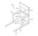
図1は、本発明の一実施の形態のショッピングカート101を示す斜視図である。ショッピングカート101は、商品を収納して移動自在なカート本体201を主体に構成されている。カート本体201は、四隅に移動用のキャスタ203が設けられた下部フレーム205が、商品を収納する収納カゴ202を支持するように構成されている。収納カゴ202の一面側には、移動に際して顧客が把持するためのハンドル204が設けられている。以下、ショッピングカート101について、ハンドル204側を手前側と、その反対側を先端側という。収納カゴ202の手前側の面は、下端を自由端として開閉可能な開閉面202aとなっている。 FIG. 1 is a perspective view showing a
手前側の二つのキャスタ203には、ロック部として電子錠281が設けられている。電子錠281は、キャスタ203の車輪203cの回転を規制することでカート本体201の移動を解除自在にロックする。 The two
また、カート本体201には、収納カゴ202の左右部分及び下部フレーム205の左右部分に、接触による圧力を検知する接触センサ291が検知部として設けられている。 The
収納カゴ202のハンドル204側の位置には、カート端末211が取り付けられている。カート端末211のハウジング211aには、ハンドル204側に位置する顧客に向けて情報を表示する表示部としてのLCD213が設けられている。LCD213の表示面には、入力部としてのタッチパネル214が取り付けられている。カート端末211には、RFIDリーダライタ215が一体に設けられている。つまり、RFIDリーダライタ215のハウジング215aとカート端末211のハウジング211aとは互いに連結している。ハウジング215aの中には、電子マネー媒体としてカードC1(図7参照)に設けられたRFIDチップC2(図7参照)と無線通信を実行するためのアンテナ215b(図7参照)が埋設されている。RFIDチップC2は、現金と等価値を有する電子マネーを記憶することが可能である。なお、電子マネー媒体は、RFIDチップC2を備える携帯電話機等であってもよい。 A
カート端末211には、RFIDタグ451が取り付けられている。RFIDタグ451には、ショッピングカート101ごとに固有のカートコードが記憶されている。RFIDタグ451は、カート本体201に設けられていてもよい。RFIDタグ451に記憶されたカートコードは、店舗内に設置された後述する店舗RFIDリーダライタ401(図6参照)によって読み取られる。 An
図2は、キャスタ203と電子錠281とを示す斜視図である。キャスタ203は、車輪203cを保持フレーム203dが回転自在に保持する構成である。保持フレーム203dには電子錠281の本体部281bが固定された突出片203eが一体的に設けられている。電子錠281の本体部281bはソレノイド(図視せず)を内蔵する。電子錠281は、ソレノイドへの通電によって棒状の鍵部281aは車輪203cに向けて突出自在となっている。そして、突出した状態の鍵部281aが車輪203cのスポーク203a同士の間の隙間203bに差し込まれることによって、キャスタ203の車輪203cはその回転が規制される。このように車輪203cの回転が規制されることによって、カート本体201の移動はロックされる。 FIG. 2 is a perspective view showing the
図3は、カート置き場301を示す斜視図である。カート置き場301は、店舗(図示せず)の床面等に固定されて一方が開放した底部フレーム311を有している。底部フレーム311の他方の両隅部には、二本の直立フレーム312が垂直に立設されている。二本の直立フレーム312には、最上位の位置にプレート313が取り付けられ、プレート313の下方位置に水平フレーム314が取り付けられている。プレート313には、各種情報の掲示が可能となっている。また、カート置き場301は、左右一対の側部フレーム315を備えている。側部フレーム315は、屈曲部分を有して一端が底部フレーム311に接続し、他端が直立フレーム312に接続している。このように構成されたカート置き場301は、ショッピングカート101のセットを許容する(図4参照)。 FIG. 3 is a perspective view showing the
また、カート置き場301は、側部フレーム315及び底部フレーム311に互いに対面するように設けられた接触部391を備えている。接触部391の設置位置は、ショッピングカート101がカート置き場301にセットされた状態で、そのショッピングカート101が有する接触センサ291と接触する位置である。 The
図4は、ショッピングカート101がカート置き場301にセットされた状態を示す斜視図である。ショッピングカート101がカート置き場301にセットされた状態では、図4に示すように、ショッピングカート101が備える接触センサ291は、それぞれ、カート置き場301に設けられた接触部391と対応して接触している。 FIG. 4 is a perspective view showing a state in which the
図5は、ショッピングカート101同士が重ね合わさった状態を示す斜視図である。前述したように、収納カゴ202の手前側の面は、開閉面202aとなっている。そして、一方のショッピングカート101の収納カゴ202の先端側を、他方のショッピングカート101の開閉面202aに押し込むことで、二台のショッピングカート101を互いに重ね合わさった状態にすることが可能となっている。このとき、手前側のショッピングカート101における収納カゴ202に設けられた接触センサ291は、先端側のショッピングカート101の収納カゴ202の側面と接触し、また、手前側のショッピングカート101における下部フレーム205に設けられた接触センサ291は、先端側のショッピングカート101の下部フレーム205と接触している。 FIG. 5 is a perspective view showing a state where the
図6は、ショッピングカート101がカート置き場301にセットされた状態を示す側面図である。カート置き場301の上方であって店舗の天井501には、店舗RFIDリーダライタ401が設置されている。店舗RFIDリーダライタ401には、カート置き場301の方向に指向性を有するアンテナ(図示せず)が内蔵されている。 FIG. 6 is a side view showing a state where the
店舗RFIDリーダライタ401は、カート置き場301にセットされた状態のショッピングカート101が有するRFIDタグ451に対して情報の読み書きが可能な通信範囲を有している。店舗RFIDリーダライタ401は、店舗のバックヤード等に配置されたストアサーバ601と通信可能に接続されている。 The store RFID reader /
なお、図6に示すように本実施の形態では、店舗RFIDリーダライタ401はカート置き場301の5台のショッピングカート101が有するRFIDタグ451と通信可能となっている。しかし、店舗RFIDリーダライタ401の通信範囲はこれに限られることはない。また、6台目以降のショッピングカート101をカバーするようにして、複数個の店舗RFIDリーダライタ401が天井501に設置されていてもよい。 As shown in FIG. 6, in this embodiment, the store RFID reader /
図7は、カート端末211のハードウェア構成を示すブロック図である。カート端末211は、各部を集中的に制御するCPU252を備えている。CPU252には、バスライン256を介して、コンピュータプログラムを含む固定データを固定的に記憶するROM253と、可変データを書き換え自在に記憶してワークエリア等として機能するRAM254と、フラッシュメモリ255とが接続されている。フラッシュメモリ255には後述する貸出テーブルTが記憶保存されており、RAM254に展開されて使用される。また、CPU252には、LCD213及びタッチパネル214がインターフェース(図示せず)及びバスライン256を介して接続されている。 FIG. 7 is a block diagram illustrating a hardware configuration of the
また、CPU252には、通信インターフェース261がバスライン256を介して接続されている。通信インターフェース261は、店舗の天井501に配置された無線通信ユニット(図示せず)と無線通信を行う。無線通信ユニットは、ストアサーバ601と接続されている。つまり、通信インターフェース261によって、カート端末211はストアサーバ601との間で通信をすることができる。カート端末211は、ストアサーバ601から広告情報等の各種情報を取得して、取得した情報をLCD213に表示させる。 In addition, a
また、ショッピングカート101のRFIDタグ451に記憶されたカートコードが店舗RFIDリーダライタ401によって読み取られた場合、ストアサーバ601は、そのカートコードによって特定されるショッピングカート101に対して、読み取られたことを伝達する読取信号を送信出力する。読取信号は、通信インターフェース261を介してCPU252が受信する。 When the store RFID reader /
さらに、CPU252には、外部機器インターフェース262がバスライン256を介して接続されている。外部機器インターフェース262には、RFIDリーダライタ215、電子錠281、接触センサ291が接続されている。CPU252は、外部機器インターフェース262を介して、外部機器インターフェース262に接続された各部の駆動制御が可能となっている。 Further, an
RFIDリーダライタ215は、カードC1に設けられたRFIDチップC2がアンテナ215bの通信可能範囲に位置付けられた場合に、RFIDチップC2との間で通信を確立する。そして、通信が確立した状態で、CPU252は、RFIDリーダライタ215を介して、RFIDチップC2に対して電子マネーの入出金処理を実行する。 The RFID reader /
接触センサ291は、圧力を検知する構成である。接触センサ291は、カート置き場301の接触部391等との接触によって圧力を検知することにより、信号を出力する。出力された信号は、CPU252に入力される。 The
電子錠281は、CPU252による制御を受けて、内蔵するソレノイドに通電を行う。 The
なお、カート端末211は、バーコード等の商品コードを読み取るバーコードスキャナを備えていてもよい。その場合、ショッピングカート101を使用する顧客は、自ら商品に付された商品コードを読み取らせることになる。そして、CPU252は、読み取られた商品コードに基づきストアサーバ601に問合せを行って単価を取得し、取得した単価から決済金額を算出する。 The
ここで、CPU252を主体とするマイクロコンピュータは、CPU252がROM253に記憶されたコンピュータプログラムに従い各種情報処理を実行することから、情報処理部251を構成する。このような情報処理部251により、カート端末211は情報処理機能を発揮する。 Here, the microcomputer mainly composed of the
図8は、貸出テーブルTのデータ構成を示す模式図である。貸出テーブルTは、貸出フラグを記憶する。電子錠281がロックされている場合には、貸出フラグには「0」が記憶され、一方で、電子錠281によるロックが解除されている場合には、貸出フラグには「1」が記憶される。カート端末211のCPU252は、実行する処理に伴って貸出フラグに「0」又は「1」を記憶させる。 FIG. 8 is a schematic diagram illustrating a data configuration of the lending table T. The lending table T stores a lending flag. When the
図9は、ショッピングカート101の貸出に際して実行される処理の流れを示すフローチャートである。このフローチャートに示されている処理は、カート端末211が有するCPU252がROM253に記憶保存されているコンピュータプログラムに従い実行する各種の機能、つまり、情報処理部251によりカート端末211が発揮する情報処理機能によって実行される。 FIG. 9 is a flowchart showing a flow of processing executed when the
ショッピングカート101は、カート置き場301にセットされている。このとき、カート本体201は電子錠281によってロックされている。この状態でCPU252は、LCD213に第1の貸出画面を表示させている。第1の貸出画面は、一例として、「ショッピングカートのデポジット金額は¥5000です」という文字と、「貸出」と表示されたボタンと有している。これにより、顧客は、ショッピングカート101の使用にあたってデポジットとして5000円が必要であることを知ることができる。そして、ショッピングカート101を使用する顧客は、「貸出」と表示されたボタンをタッチ操作することになる。 The
顧客の操作によって「貸出」と表示されたボタンがタッチパネル214によりタッチ指定されることにより、ショッピングカート101の貸出が宣言されたならば(ステップS101のY)、CPU252は、LCD213に第2の貸出画面を表示させる。第2の貸出画面は、一例として、「デポジット金額を引き落とします」という文字と、カードC1をRFIDリーダライタ215の上面に位置付ける操作を顧客に示す絵柄とを有している。これにより、顧客は、デポジット引き落としのためにすべき操作について知ることができる。 When the button displayed as “rental” by the operation of the customer is touch-designated on the
顧客によってカードC1がRFIDリーダライタ215の上面位置に位置付けられることにより、RFIDリーダライタ215とカードC1のRFIDチップC2との間に通信が確立し、CPU252は、RFIDリーダライタ215を介してカードC1に設けられたRFIDチップC2に記憶された電子マネーから、デポジット金額(5000円)分の電子マネーの引き落としをする処理を実行する(ステップS102)。デポジット引き落としの後、CPU252は、貸出テーブルTの貸出フラグに「1」を記憶させる(ステップS103)。そして、CPU252は、電子錠281にロックを解除させる(ステップS104)。つまり、デポジット引き落としを条件として、電子錠281によるロックが解除されることになる。 Communication between the RFID reader /
電子錠281によるロックが解除されたショッピングカート101は使用可能となる。顧客は、ショッピングカート101のハンドル204を把持して店舗内を移動する。この際、商品棚(図示せず)から購入を希望する商品(図示せず)を取り、取った商品を収納カゴ202に収納する。購入を希望する商品の収納カゴ202への収納を終えたならば、顧客はショッピングカート101と共に店舗内の決済場所(図示せず)まで移動することになる。顧客は決済場所で決済を行う。このとき、RFIDリーダライタ215を使用した電子マネーによる決済を行うことができる。決済の後、顧客は、購入した商品の袋詰め等を行い、最終的にショッピングカート101を再びカート置き場301に返却する。 The
図10は、ショッピングカート101の返却に際して実行される処理の流れを示すフローチャートである。このフローチャートに示されている処理も、情報処理部251によりカート端末211が発揮する情報処理機能によって実行される。 FIG. 10 is a flowchart showing a flow of processing executed when the
ショッピングカート101を返却する場合、顧客は、電子錠281によるロックが解除されている状態のショッピングカート101をカート置き場301にセットする。ショッピングカート101がカート置き場301に移動すると、ショッピングカート101が有するRFIDタグ451のカートコードは読み取られ、ショッピングカート101のCPU252は、ストアサーバ601から読取信号を受信する。そして、ショッピングカート101が備える接触センサ291は、カート置き場301の接触部391と接触して圧力を検知する。こうしてショッピングカート101のカート置き場301へのセットが検知される(ステップS201のY)。つまり、CPU252が読取信号を受信した状態で接触センサ291が圧力を検知することによって初めて、カート置き場301へのセットが検知されることになる。こうして、カート置き場301以外の別の位置で接触センサ291が圧力を検知したような場合(例えばカート置き場301の以外の位置で2台のショッピングカート101同士を重ね合わせた場合)には、カート置き場301へのセットとはみなされない。なお、CPU252が読取信号を受信した後、所定時間内に接触センサ291が圧力を検知しなければ、読取信号の受信を無効にするようにしてもよい。そして、CPU252が読取信号を受信していない状態で、接触センサ291が圧力を検知した場合には、所定の警告画面をLCD213に表示させるようにしてもよい。 When returning the
カート置き場301に既に別のショッピングカート101がセットされている場合には、返却するショッピングカート101の収納カゴ202の先端側部分を既にカート置き場301にセットされたショッピングカート101の開閉面202aに押し込むことになる。この場合、接触センサ291は、別のショッピングカート101との接触により圧力を検知する。こうして、ショッピングカート101のカート置き場301へのセットが検知されたことになる。 When another
接触センサ291が圧力を検知すると、接触部391から信号が出力されてCPU252に入力され、CPU252は、次に、LCD213に第1の返却画面を表示させる。第1の返却画面は、一例として、「ショッピングカートを返却しますか?」という文字と、「はい」と「いいえ」と表示された選択ボタンとを有している。これにより、顧客は、ショッピングカート101を返却するか否かについて選択することができる。 When the
顧客の操作によって「いいえ」に対応する選択ボタンがタッチパネル214によってタッチ指定されたならば、CPU252は、そのまま処理を終了する(ステップS202のN)。一方、「はい」に対応する選択ボタンがタッチ指定されることによりショッピングカート101の返却が宣言されたならば(ステップS202のY)、CPU252は、電子錠281にカート本体201の移動をロックさせる(ステップS203)。そして、CPU252は、貸出テーブルTの貸出フラグに記憶されている「1」を消去して「0」を記憶させ(ステップS204)、LCD213に第2の返却画面を表示させる。第2の返却画面は、一例として、「デポジットを払い戻します」という文字と、カードC1をRFIDリーダライタ215の上面に位置付ける操作を顧客に示す絵柄とを有している。 If the selection button corresponding to “No” is touch-designated by the
顧客によってカードC1がRFIDリーダライタ215の上面位置に位置付けられたならば、CPU252は、RFIDリーダライタ215を介してカードC1に設けられたRFIDチップC2にデポジット金額(5000円)分の電子マネーを払い戻し(ステップS205)、処理を終了する。 When the card C1 is positioned at the upper surface position of the RFID reader /
以上説明したように、本実施の形態によれば、電子錠281によるロックを解除してショッピングカート101を使用可能とするためにはデポジットが必要となることから、ショッピングカート101を使用した顧客による返却行動を促進して返却率を高めて、ショッピングカート101の紛失を防止することができる。また、ショッピングカート101が備えるRFIDリーダライタ215を利用してRFIDチップC2からデポジット金額分の電子マネーを引き落とすため、ショッピングカート101の貸出及び返却に人員を介在させる必要がなく、店舗として管理負担も小さいものとなる。 As described above, according to the present embodiment, since a deposit is required to unlock the
101…ショッピングカート,201…カート本体,215…RFIDリーダライタ,215b…アンテナ,251…情報処理部,281…電子錠(ロック部),291…接触センサ(検知部),301…カート置き場,C1…カード(電子マネー媒体),C2…RFIDチップ DESCRIPTION OF
Claims (2)
Translated fromJapanese情報処理機能を果たす情報処理部と、
前記カート本体の移動を解除自在にロックするロック部と、
アンテナを有し当該アンテナの通信可能範囲に位置付けられた電子マネー媒体が有する電子マネーを記憶するRFIDチップとの間で当該アンテナを介して通信を実行するRFIDリーダライタと、
前記ロック部により前記カート本体の移動がロックされている状態で、前記情報処理機能を用いて、前記RFIDリーダライタを介して前記RFIDチップに記憶された電子マネーからデポジット金額分の電子マネーを引き落とす手段と、
前記引き落としを条件として、前記情報処理機能を用いて、前記ロック部にロックを解除させる手段と、
前記情報処理機能を用いて、前記ロック部に前記カート本体の移動をロックさせる手段と、
前記ロック部により前記カート本体の移動がロックされたならば、前記情報処理機能を用いて、前記RFIDリーダライタを介して前記引き落としたデポジット金額分の電子マネーを前記RFIDチップに払い戻す手段と、
を備えるショッピングカート。A cart body that stores goods and is movable,
An information processing unit that performs an information processing function;
A lock portion for releasably locking the movement of the cart body;
An RFID reader / writer that performs communication via the antenna with an RFID chip that stores the electronic money of an electronic money medium that has an antenna and is positioned within the communicable range of the antenna;
With the movement of the cart body locked by the lock unit, the electronic money corresponding to the deposit amount is deducted from the electronic money stored in the RFID chip via the RFID reader / writer using the information processing function. Means,
Means for causing the lock part to unlock using the information processing function on the condition of the withdrawal;
Means for locking movement of the cart body to the lock unit using the information processing function;
If the movement of the cart body is locked by the lock unit, means for using the information processing function to pay back the electronic money for the deposited amount withdrawn to the RFID chip via the RFID reader / writer;
Shopping cart with.
前記検知部によってカート置き場へのセットが検知された場合に、前記ロック部に前記カート本体の移動をロックさせるようにした、
請求項1記載のショッピングカート。It has a detector that detects the set in the cart storage area.
When the set to the cart storage area is detected by the detection unit, the movement of the cart body is locked to the lock unit.
The shopping cart according to claim 1.
Priority Applications (1)
| Application Number | Priority Date | Filing Date | Title |
|---|---|---|---|
| JP2006298490AJP4684982B2 (en) | 2006-11-02 | 2006-11-02 | Shopping cart |
Applications Claiming Priority (1)
| Application Number | Priority Date | Filing Date | Title |
|---|---|---|---|
| JP2006298490AJP4684982B2 (en) | 2006-11-02 | 2006-11-02 | Shopping cart |
Publications (2)
| Publication Number | Publication Date |
|---|---|
| JP2008117102Atrue JP2008117102A (en) | 2008-05-22 |
| JP4684982B2 JP4684982B2 (en) | 2011-05-18 |
Family
ID=39502969
Family Applications (1)
| Application Number | Title | Priority Date | Filing Date |
|---|---|---|---|
| JP2006298490AExpired - Fee RelatedJP4684982B2 (en) | 2006-11-02 | 2006-11-02 | Shopping cart |
Country Status (1)
| Country | Link |
|---|---|
| JP (1) | JP4684982B2 (en) |
Cited By (17)
| Publication number | Priority date | Publication date | Assignee | Title |
|---|---|---|---|---|
| WO2010117451A3 (en)* | 2009-04-06 | 2010-12-29 | Wheellogic Llc | Systems and methods for managing shopping cart and other wheeled conveyance assets |
| JP2011195129A (en)* | 2010-03-24 | 2011-10-06 | Takigen Mfg Co Ltd | Locking device of hand truck |
| US8115623B1 (en) | 2011-03-28 | 2012-02-14 | Robert M Green | Method and system for hand basket theft detection |
| CN108749904A (en)* | 2018-05-24 | 2018-11-06 | 武汉天喻聚联网络有限公司 | Shopping clearing vehicle based on RFID and its application method |
| JP2019051916A (en)* | 2017-09-12 | 2019-04-04 | 株式会社ゴビ | Shopping cart and management system thereof |
| IT201700113828A1 (en)* | 2017-10-10 | 2019-04-10 | Metta Simone | TROLLEY SAFETY DEVICE AND PROCEDURE |
| CN110656823A (en)* | 2018-06-28 | 2020-01-07 | 南京铭富信息科技有限公司 | Electronic lock of shopping cart |
| CN110656822A (en)* | 2018-06-28 | 2020-01-07 | 南京铭富信息科技有限公司 | Electronic lock of shopping cart |
| JP2020140274A (en)* | 2019-02-27 | 2020-09-03 | 日本電気株式会社 | Information processing device, server, information processing system, information processing method, and information processing program |
| JP2020140273A (en)* | 2019-02-27 | 2020-09-03 | 日本電気株式会社 | Information processing device, server, information processing system, information processing method, and information processing program |
| EP3713043A1 (en)* | 2019-03-22 | 2020-09-23 | Toshiba TEC Kabushiki Kaisha | Cart storage system and power feed system |
| JP2020156283A (en)* | 2019-03-22 | 2020-09-24 | 東芝テック株式会社 | Cart storage system and power supply system |
| JP2021010274A (en)* | 2019-07-02 | 2021-01-28 | 東芝テック株式会社 | Non-contact power supply device |
| JP2021092860A (en)* | 2019-12-06 | 2021-06-17 | 東芝テック株式会社 | Information processing device and program |
| JP2021529625A (en)* | 2018-07-08 | 2021-11-04 | フリーテイル テクノロジーズ リミテッドFreetail Technologies Ltd. | Cart lock and distributor |
| WO2022024681A1 (en)* | 2020-07-28 | 2022-02-03 | 東芝テック株式会社 | Contactless power feeding device |
| WO2023157084A1 (en)* | 2022-02-15 | 2023-08-24 | 三菱電機ビルソリューションズ株式会社 | Mobile body information providing system and mobile body receiving device |
Families Citing this family (2)
| Publication number | Priority date | Publication date | Assignee | Title |
|---|---|---|---|---|
| CN106741083A (en)* | 2016-12-28 | 2017-05-31 | 合肥工业大学 | Supermarket self-help shopping cart and application method |
| CN109858994A (en)* | 2018-12-20 | 2019-06-07 | 深圳推推应用技术有限公司 | A kind of promotion method and mobile terminal of shopping cart |
Citations (3)
| Publication number | Priority date | Publication date | Assignee | Title |
|---|---|---|---|---|
| JPS6263394A (en)* | 1985-07-22 | 1987-03-20 | シテイ− ホウイ−ルズ リミテツド | Controller |
| JP2002197547A (en)* | 2000-12-27 | 2002-07-12 | Toshiba Tec Corp | Point service system, point service method and rental item automatic lending / returning device |
| WO2006081793A2 (en)* | 2005-02-03 | 2006-08-10 | Horst Sonnendorfer | Supermarket trolley |
- 2006
- 2006-11-02JPJP2006298490Apatent/JP4684982B2/ennot_activeExpired - Fee Related
Patent Citations (4)
| Publication number | Priority date | Publication date | Assignee | Title |
|---|---|---|---|---|
| JPS6263394A (en)* | 1985-07-22 | 1987-03-20 | シテイ− ホウイ−ルズ リミテツド | Controller |
| JP2002197547A (en)* | 2000-12-27 | 2002-07-12 | Toshiba Tec Corp | Point service system, point service method and rental item automatic lending / returning device |
| WO2006081793A2 (en)* | 2005-02-03 | 2006-08-10 | Horst Sonnendorfer | Supermarket trolley |
| JP2008528361A (en)* | 2005-02-03 | 2008-07-31 | ゾンネンドルフェール、ホルスト | Shopping cart |
Cited By (34)
| Publication number | Priority date | Publication date | Assignee | Title |
|---|---|---|---|---|
| WO2010117451A3 (en)* | 2009-04-06 | 2010-12-29 | Wheellogic Llc | Systems and methods for managing shopping cart and other wheeled conveyance assets |
| JP2011195129A (en)* | 2010-03-24 | 2011-10-06 | Takigen Mfg Co Ltd | Locking device of hand truck |
| US8115623B1 (en) | 2011-03-28 | 2012-02-14 | Robert M Green | Method and system for hand basket theft detection |
| JP2019051916A (en)* | 2017-09-12 | 2019-04-04 | 株式会社ゴビ | Shopping cart and management system thereof |
| IT201700113828A1 (en)* | 2017-10-10 | 2019-04-10 | Metta Simone | TROLLEY SAFETY DEVICE AND PROCEDURE |
| CN108749904A (en)* | 2018-05-24 | 2018-11-06 | 武汉天喻聚联网络有限公司 | Shopping clearing vehicle based on RFID and its application method |
| CN110656823A (en)* | 2018-06-28 | 2020-01-07 | 南京铭富信息科技有限公司 | Electronic lock of shopping cart |
| CN110656822A (en)* | 2018-06-28 | 2020-01-07 | 南京铭富信息科技有限公司 | Electronic lock of shopping cart |
| JP2021529625A (en)* | 2018-07-08 | 2021-11-04 | フリーテイル テクノロジーズ リミテッドFreetail Technologies Ltd. | Cart lock and distributor |
| JP7601755B2 (en) | 2018-07-08 | 2024-12-17 | フリーテイル アクイジション エルエルシー | Cart Locks and Dispensing Devices |
| JP7429353B2 (en) | 2019-02-27 | 2024-02-08 | 日本電気株式会社 | Information processing device, information processing system, information processing method, and information processing program |
| JP7247652B2 (en) | 2019-02-27 | 2023-03-29 | 日本電気株式会社 | Information processing device, server, information processing system, information processing method, and information processing program |
| JP2020140273A (en)* | 2019-02-27 | 2020-09-03 | 日本電気株式会社 | Information processing device, server, information processing system, information processing method, and information processing program |
| JP2020140274A (en)* | 2019-02-27 | 2020-09-03 | 日本電気株式会社 | Information processing device, server, information processing system, information processing method, and information processing program |
| JP2024036407A (en)* | 2019-02-27 | 2024-03-15 | 日本電気株式会社 | Information processing device, information processing system, information processing method, and information processing program |
| JP2025023228A (en)* | 2019-02-27 | 2025-02-14 | 日本電気株式会社 | Information processing device, information processing system, information processing method, and information processing program |
| JP7605351B2 (en) | 2019-02-27 | 2024-12-24 | 日本電気株式会社 | Information processing device, information processing system, information processing method, and information processing program |
| JP2023073292A (en)* | 2019-02-27 | 2023-05-25 | 日本電気株式会社 | Information processing device, information processing system, information processing method, and information processing program |
| JP7251210B2 (en) | 2019-02-27 | 2023-04-04 | 日本電気株式会社 | Information processing device, server, information processing system, information processing method, and information processing program |
| EP3713043A1 (en)* | 2019-03-22 | 2020-09-23 | Toshiba TEC Kabushiki Kaisha | Cart storage system and power feed system |
| JP7214524B2 (en) | 2019-03-22 | 2023-01-30 | 東芝テック株式会社 | Cart storage system and power supply system |
| US11318976B2 (en) | 2019-03-22 | 2022-05-03 | Toshiba Tec Kabushiki Kaisha | Cart storage system and power feed system |
| JP2020156283A (en)* | 2019-03-22 | 2020-09-24 | 東芝テック株式会社 | Cart storage system and power supply system |
| JP2021010274A (en)* | 2019-07-02 | 2021-01-28 | 東芝テック株式会社 | Non-contact power supply device |
| JP2021092860A (en)* | 2019-12-06 | 2021-06-17 | 東芝テック株式会社 | Information processing device and program |
| JP2022024705A (en)* | 2020-07-28 | 2022-02-09 | 東芝テック株式会社 | Contactless power feeding device |
| JP7514683B2 (en) | 2020-07-28 | 2024-07-11 | 東芝テック株式会社 | Non-contact power supply device |
| US12046919B2 (en) | 2020-07-28 | 2024-07-23 | Toshiba Tec Kabushiki Kaisha | Contactless power feeding device |
| EP4190670A4 (en)* | 2020-07-28 | 2024-10-23 | Toshiba TEC Kabushiki Kaisha | Contactless power feeding device |
| WO2022024681A1 (en)* | 2020-07-28 | 2022-02-03 | 東芝テック株式会社 | Contactless power feeding device |
| CN118679481A (en)* | 2022-02-15 | 2024-09-20 | 三菱电机楼宇解决方案株式会社 | Mobile object information providing system and mobile object storage device |
| JPWO2023157084A1 (en)* | 2022-02-15 | 2023-08-24 | ||
| WO2023157084A1 (en)* | 2022-02-15 | 2023-08-24 | 三菱電機ビルソリューションズ株式会社 | Mobile body information providing system and mobile body receiving device |
| JP7614442B2 (en) | 2022-02-15 | 2025-01-15 | 三菱電機ビルソリューションズ株式会社 | MOBILE OBJECT INFORMATION PROVIDING SYSTEM AND MOBILE OBJECT STORAGE DEVICE |
Also Published As
| Publication number | Publication date |
|---|---|
| JP4684982B2 (en) | 2011-05-18 |
Similar Documents
| Publication | Publication Date | Title |
|---|---|---|
| JP4684982B2 (en) | Shopping cart | |
| US7944354B2 (en) | System and method for shopping cart security | |
| JP5216726B2 (en) | Self-checkout terminal device | |
| JP7534229B2 (en) | FRAUDULENT ACTIVITY RECOGNITION DEVICE, ITS CONTROL PROGRAM, AND FRAUDULENT ACTIVITY RECOGNITION METHOD | |
| CN203084827U (en) | Intelligent interactive experience self-help vending machine | |
| US20170132601A1 (en) | Information processing device and management system | |
| JP5444656B2 (en) | POS system | |
| JP6569057B2 (en) | Checkout processing system and store management system | |
| JP5053343B2 (en) | Self-checkout terminal | |
| CN205563695U (en) | Receipts snow cover is put with intelligence settlement network payment and theftproof function | |
| CN106815959A (en) | supermarket anti-theft method and system | |
| JP6115034B2 (en) | POS system, registration device, and program | |
| CN112020733A (en) | Article management system and article management method | |
| JP7551879B2 (en) | Terminal and program | |
| JP2016071787A (en) | Merchandise settlement system and merchandise settlement method | |
| JP7554693B2 (en) | Product sales data processing device and program | |
| JP2009032006A (en) | Product sales data processing device | |
| JP2023118460A (en) | Monitoring device and program | |
| JP7646928B2 (en) | FRAUDULENT ACTIVITY RECOGNITION DEVICE, ITS CONTROL PROGRAM, AND FRAUDULENT ACTIVITY RECOGNITION METHOD | |
| JP5623831B2 (en) | Product code reader and program | |
| JP5943078B2 (en) | Information processing apparatus and return object setting method | |
| JP2023181246A (en) | Sales systems, payment devices, programs | |
| JP6416987B2 (en) | Product sales data processing device, information terminal, and control program | |
| JP5042944B2 (en) | Product sales system and product sales data processing device | |
| JP7546876B2 (en) | Product sales data processing system and program |
Legal Events
| Date | Code | Title | Description |
|---|---|---|---|
| A621 | Written request for application examination | Free format text:JAPANESE INTERMEDIATE CODE: A621 Effective date:20080911 | |
| RD02 | Notification of acceptance of power of attorney | Free format text:JAPANESE INTERMEDIATE CODE: A7422 Effective date:20091030 | |
| RD04 | Notification of resignation of power of attorney | Free format text:JAPANESE INTERMEDIATE CODE: A7424 Effective date:20100201 | |
| A977 | Report on retrieval | Free format text:JAPANESE INTERMEDIATE CODE: A971007 Effective date:20101025 | |
| A131 | Notification of reasons for refusal | Free format text:JAPANESE INTERMEDIATE CODE: A131 Effective date:20101102 | |
| A521 | Request for written amendment filed | Free format text:JAPANESE INTERMEDIATE CODE: A523 Effective date:20101222 | |
| TRDD | Decision of grant or rejection written | ||
| A01 | Written decision to grant a patent or to grant a registration (utility model) | Free format text:JAPANESE INTERMEDIATE CODE: A01 Effective date:20110208 | |
| A01 | Written decision to grant a patent or to grant a registration (utility model) | Free format text:JAPANESE INTERMEDIATE CODE: A01 | |
| A61 | First payment of annual fees (during grant procedure) | Free format text:JAPANESE INTERMEDIATE CODE: A61 Effective date:20110209 | |
| FPAY | Renewal fee payment (event date is renewal date of database) | Free format text:PAYMENT UNTIL: 20140218 Year of fee payment:3 | |
| R150 | Certificate of patent or registration of utility model | Free format text:JAPANESE INTERMEDIATE CODE: R150 | |
| LAPS | Cancellation because of no payment of annual fees |