JP2008114339A - manipulator - Google Patents
manipulatorDownload PDFInfo
- Publication number
- JP2008114339A JP2008114339AJP2006300530AJP2006300530AJP2008114339AJP 2008114339 AJP2008114339 AJP 2008114339AJP 2006300530 AJP2006300530 AJP 2006300530AJP 2006300530 AJP2006300530 AJP 2006300530AJP 2008114339 AJP2008114339 AJP 2008114339A
- Authority
- JP
- Japan
- Prior art keywords
- gear
- cylinder
- manipulator
- rotation
- cylindrical body
- Prior art date
- Legal status (The legal status is an assumption and is not a legal conclusion. Google has not performed a legal analysis and makes no representation as to the accuracy of the status listed.)
- Pending
Links
Images


Classifications
- A—HUMAN NECESSITIES
- A61—MEDICAL OR VETERINARY SCIENCE; HYGIENE
- A61B—DIAGNOSIS; SURGERY; IDENTIFICATION
- A61B34/00—Computer-aided surgery; Manipulators or robots specially adapted for use in surgery
- A61B34/70—Manipulators specially adapted for use in surgery
- A—HUMAN NECESSITIES
- A61—MEDICAL OR VETERINARY SCIENCE; HYGIENE
- A61B—DIAGNOSIS; SURGERY; IDENTIFICATION
- A61B34/00—Computer-aided surgery; Manipulators or robots specially adapted for use in surgery
- A61B34/70—Manipulators specially adapted for use in surgery
- A61B34/71—Manipulators operated by drive cable mechanisms
- A—HUMAN NECESSITIES
- A61—MEDICAL OR VETERINARY SCIENCE; HYGIENE
- A61B—DIAGNOSIS; SURGERY; IDENTIFICATION
- A61B17/00—Surgical instruments, devices or methods
- A61B2017/00831—Material properties
- A61B2017/00929—Material properties isolating electrical current
- A—HUMAN NECESSITIES
- A61—MEDICAL OR VETERINARY SCIENCE; HYGIENE
- A61B—DIAGNOSIS; SURGERY; IDENTIFICATION
- A61B17/00—Surgical instruments, devices or methods
- A61B17/28—Surgical forceps
- A61B17/29—Forceps for use in minimally invasive surgery
- A61B2017/2926—Details of heads or jaws
- A61B2017/2927—Details of heads or jaws the angular position of the head being adjustable with respect to the shaft
- A—HUMAN NECESSITIES
- A61—MEDICAL OR VETERINARY SCIENCE; HYGIENE
- A61B—DIAGNOSIS; SURGERY; IDENTIFICATION
- A61B17/00—Surgical instruments, devices or methods
- A61B17/28—Surgical forceps
- A61B17/29—Forceps for use in minimally invasive surgery
- A61B2017/2926—Details of heads or jaws
- A61B2017/2932—Transmission of forces to jaw members
- A61B2017/2939—Details of linkages or pivot points
- A—HUMAN NECESSITIES
- A61—MEDICAL OR VETERINARY SCIENCE; HYGIENE
- A61B—DIAGNOSIS; SURGERY; IDENTIFICATION
- A61B90/00—Instruments, implements or accessories specially adapted for surgery or diagnosis and not covered by any of the groups A61B1/00 - A61B50/00, e.g. for luxation treatment or for protecting wound edges
- A61B90/04—Protection of tissue around surgical sites against effects of non-mechanical surgery, e.g. laser surgery
- A61B2090/0409—Specification of type of protection measures
- A61B2090/0427—Prevention of contact
Landscapes
- Health & Medical Sciences (AREA)
- Surgery (AREA)
- Engineering & Computer Science (AREA)
- Life Sciences & Earth Sciences (AREA)
- Medical Informatics (AREA)
- Robotics (AREA)
- Biomedical Technology (AREA)
- Heart & Thoracic Surgery (AREA)
- Nuclear Medicine, Radiotherapy & Molecular Imaging (AREA)
- Molecular Biology (AREA)
- Animal Behavior & Ethology (AREA)
- General Health & Medical Sciences (AREA)
- Public Health (AREA)
- Veterinary Medicine (AREA)
- Manipulator (AREA)
- Surgical Instruments (AREA)
Abstract
Translated fromJapaneseDescription
Translated fromJapanese本発明は、操作部を操作することで動力伝達部材を介して作業部を作動させるマニピュレータに関する。 The present invention relates to a manipulator that operates a working unit via a power transmission member by operating an operating unit.
従来、先端作業部と手元操作部とを連結部により連結した医療用マニピュレータが用いられており、このような医療用マニピュレータでは、内視鏡観察下に、操作部を把持操作して作業部を体腔内に挿入し、該作業部を作動させて生体組織に各種処置を行う。 Conventionally, a medical manipulator in which a distal working portion and a hand operating portion are connected by a connecting portion has been used. In such a medical manipulator, the operating portion is gripped and operated while observing an endoscope. It is inserted into a body cavity and the working unit is operated to perform various treatments on the living tissue.
特許文献1及び2には、生体組織を把持する一対のグリッパが作業部に配設されたマニピュレータが記載されている。前記一対のグリッパは、グリッパ軸を中心として開閉作動されると共に、ピッチ軸、ロール軸等を中心として一体的に回転作動される。この場合、操作部のモータ出力軸と作業部のプーリとには連結部を介してワイヤが巻回されており、作業部の作動に必要なトルクはモータからワイヤを介して前記プーリへ、さらに、該プーリから歯車等へと順次伝達される。
ところで、腹腔鏡下手術等に用いる鉗子をモノポーラ電気メスとして利用する場合には、操作部近傍に設けられた端子から、導電性の構造部材や動力伝達部材を利用して先端部のグリッパやブレードやフック等に通電させて所望の処置を行う。この場合、先端のグリッパ等以外の部分が体内の組織に触れても通電しないように、鉗子シャフト部は絶縁部材等で被覆、コーティングされている。 By the way, when using forceps used for laparoscopic surgery as a monopolar electric knife, a gripper or blade at the tip is used from a terminal provided in the vicinity of the operation unit using a conductive structural member or power transmission member. Energize the hook or the like to perform the desired treatment. In this case, the forceps shaft portion is covered and coated with an insulating member or the like so that a portion other than the tip gripper or the like does not energize even if it touches the tissue in the body.
一方、マニピュレータ(多自由度鉗子)をモノポーラ電気メスとして利用する場合においても、上記の鉗子と同様に、操作部近傍に設けられた端子から、導電性の構造部材や動力伝達部材を利用して先端部のグリッパ等に通電させ、所望の処置を行うことが可能である。この場合にも、鉗子シャフト部は、絶縁部材等で被覆、コーティングすることにより、鉗子シャフト部から体内組織への通電を避けることができる。 On the other hand, when a manipulator (multi-degree-of-freedom forceps) is used as a monopolar electric knife, similarly to the above-described forceps, a conductive structural member or power transmission member is used from a terminal provided near the operation unit. It is possible to energize the gripper or the like at the tip and perform a desired treatment. Also in this case, the forceps shaft portion can be covered and coated with an insulating member or the like to avoid energization from the forceps shaft portion to the body tissue.
しかしながら、このようなマニピュレータにおいて、ピッチ軸やヨー軸等の曲げ動作を伴う関節部では、動力伝達部材であるワイヤや歯車等が露出している。このため、これら露出部分が生体組織に接触、通電してしまう可能性があるが、関節部に配置されたワイヤや歯車等は動力伝達部材であるため、絶縁部材を用いたり、絶縁被覆や絶縁コーティング等を施したりすることが困難である。 However, in such a manipulator, a wire, a gear, or the like, which is a power transmission member, is exposed at a joint portion that involves a bending operation such as a pitch axis or a yaw axis. For this reason, there is a possibility that these exposed parts may contact and energize living tissue. However, since wires, gears, and the like arranged at the joints are power transmission members, insulating members may be used, insulating coatings or insulating materials may be used. It is difficult to apply a coating or the like.
関節部を絶縁性のあるジャバラやフレキシブルカバー、ハードカバー等で完全に覆う方法も考えられるが、屈曲の動作範囲が比較的大きな関節部にジャバラやフレキシブルカバー等を装着するのは困難であり、また、該ジャバラ等のスペースが必要となってしまう。ハードカバーで覆う場合にも、機構的な工夫が必要となり、さらにその装着には大きなスペースを要し、外径が非常に大きいものとなってしまう。そして、このように関節部を覆う方法では、十分な密閉状態を保持することができなければ体液や血液が関節部に浸入し、前記ジャバラ等が逆に邪魔になり、洗浄性の面で問題が生じることになる。すなわち、マニピュレータの洗浄性や可動範囲等を考慮した場合には、関節部は適度に開口していることが望ましい。 Although it is conceivable to completely cover the joint with an insulating bellows, flexible cover, hard cover, etc., it is difficult to attach the bellows, flexible cover, etc. to the joint with a relatively large bending range, Further, a space such as the bellows is required. In the case of covering with a hard cover, mechanical ingenuity is required, and a large space is required for the mounting, and the outer diameter becomes very large. And, in the method of covering the joint part in this way, if a sufficiently sealed state cannot be maintained, body fluid and blood will enter the joint part, and the bellows etc. will be obstructive on the contrary, and there will be a problem in terms of cleanability Will occur. That is, it is desirable that the joint portion is appropriately opened in consideration of the cleaning properties and the movable range of the manipulator.
本発明はこのような課題を考慮してなされたものであり、関節部において、動力伝達部材であるワイヤや歯車等が作業対象に接触することを防止できるマニピュレータを提供することを目的とする。 The present invention has been made in view of such problems, and an object of the present invention is to provide a manipulator that can prevent a power transmission member, such as a wire or a gear, from coming into contact with a work target at a joint.
本発明に係るマニピュレータは、操作部と、前記操作部に設けられた第1入力部及び第2入力部と、前記第1入力部及び第2入力部の操作に基づいて回転する第1回転源及び第2回転源と、尾端側が前記操作部、又は、前記第1回転源及び第2回転源を回転駆動する駆動部に連結された連結部と、前記連結部の先端側に設けられた第1関節軸と、前記第1関節軸と交差する第2関節軸と、前記第1関節軸に軸支された第1筒体及び第2筒体と、後方部が前記第1回転源に巻き掛けられ、前方部が前記第1筒体に巻き掛けられた第1可撓性動力伝達部材と、後方部が前記第2回転源に巻き掛けられ、前方部が前記第2筒体に巻き掛けられた第2可撓性動力伝達部材と、前記第1筒体の回転に連動し、前記第1関節軸を中心として動作する駆動機構部と、前記駆動機構部の前方に設けられ、前記第2筒体の回転に連動し、前記第2関節軸を中心として動作する作用部と、前記第1関節軸に軸支された第1絶縁部材とを有することを特徴とする。 The manipulator according to the present invention includes an operation unit, a first input unit and a second input unit provided in the operation unit, and a first rotation source that rotates based on an operation of the first input unit and the second input unit. And the second rotation source, the tail end side being provided on the distal end side of the connection portion, the connection portion connected to the operation portion, or the drive portion that rotationally drives the first rotation source and the second rotation source. A first joint axis, a second joint axis intersecting the first joint axis, a first cylinder and a second cylinder supported by the first joint axis, and a rear portion serving as the first rotation source The first flexible power transmission member is wound around, the front part is wound around the first cylinder, the rear part is wound around the second rotation source, and the front part is wound around the second cylinder. A second flexible power transmission member that is hung and a drive unit that operates around the first joint axis in conjunction with the rotation of the first cylindrical body. A first working portion that is provided in front of the drive mechanism portion, operates in association with the rotation of the second cylindrical body, and operates around the second joint axis, and is supported by the first joint shaft. And an insulating member.
本発明に係るマニピュレータによれば、関節部において動力伝達部材であるワイヤや歯車等が作業対象に接触することを防止することができる。 According to the manipulator according to the present invention, it is possible to prevent a wire, a gear, or the like, which is a power transmission member, from coming into contact with the work target at the joint portion.
以下、本発明に係るマニピュレータ(多自由度鉗子)について第1及び第2の実施形態とその変形例を挙げ、添付の図1〜図29を参照しながら説明する。第1の実施形態に係るマニピュレータ10a及びその変形例に係るマニピュレータ10b(図1参照)、第2の実施形態に係るマニピュレータ10c及びその変形例に係るマニピュレータ10d(図17参照)は、医療用であって腹腔鏡下手術等に用いられるものである。また、各実施形態に係る作業部12a〜12dは、マニピュレータ10a〜10dの先端部に設けられた2又は3自由度の機構である。 Hereinafter, the manipulator (multi-degree-of-freedom forceps) according to the present invention will be described with reference to FIGS. The
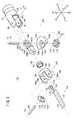
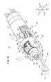
マニピュレータ10aは、先端の作業部12aから生体に対して通電し、所定の箇所を熱処理するモノポーラ電気メス機能を有する。マニピュレータ10aは、人手によって把持及び操作される基端部の操作指令部(操作部)14aと、先端部で作業を行う作業部12aと、これら作業部12aと操作指令部14aを接続する長尺な連結部16aとを有する。作業部12a及び連結部16aは細径に構成されており、患者の腹部等に設けられた小孔(トラカール)20から体腔22内に挿入可能であって、操作指令部14aの操作により体腔22内において所望の処置(熱処理)を施すことができる。 The
なお、以下の説明では、図1、図12、図17及び図24における幅方向をX方向、高さ方向をY方向、連結部16a及び連結部16b(図17参照)の延在方向をZ方向と規定する。また、右方をX1方向、左方をX2方向、上方向をY1方向、下方向をY2方向、前方をZ1方向、後方をZ2方向と規定する。さらに、特に断りのない限り、これらの方向の記載はマニピュレータ10a〜10dが中立姿勢(図2、図12、図18及び図24に示す状態の姿勢)である場合を基準として表すものとする。これらの方向は説明の便宜上のものであり、マニピュレータ10a〜10dは任意の向きで(例えば、上下を反転させて)使用可能であることはもちろんである。 In the following description, the width direction in FIGS. 1, 12, 17 and 24 is the X direction, the height direction is the Y direction, and the extending direction of the connecting
操作指令部14aは、人手によって把持されるグリップハンドル26と、該グリップハンドル26の上部から延在するアーム28と、該アーム28の先端に接続されたアクチュエータブロック(駆動部)30とを有する。グリップハンドル26には、指で操作可能なトリガーレバー32と、縦ローラ34と、横ローラ35と、スイッチ37とが設けられている。トリガーレバー32は、人差し指による引き寄せ動作が容易な位置に設けられている。縦ローラ34及び横ローラ35は、親指による回転動作が容易な位置に設けられている。 The
アクチュエータブロック30には作業部12aが有する2自由度の機構に対応して、モータ40及びモータ42が連結部16aの延在方向に沿って並列して設けられている。これらのモータ40及び42は小型細径であって、アクチュエータブロック30はコンパクトな扁平形状に構成されている。アクチュエータブロック30は、連結部16aのZ2方向端部の下方に設けられている。また、モータ40及び42は、操作指令部14a(マスタ)の指令(操作)に基づき、コントローラ45のマスタ・スレーブ制御により回転駆動される。 The
連結部16aは、アクチュエータブロック30に対して接続される基端側接続部46と、該基端側接続部46からZ1方向に向かって延在する中空の連結シャフト48とを有する。基端側接続部46には、モータ40及び42の駆動軸に接続される駆動プーリ(第1回転源)50a及び駆動プーリ(第2回転源)50bが回転自在に設けられている。駆動プーリ50a及び駆動プーリ50bには、ワイヤ(第1可撓性動力伝達部材)52及びワイヤ(第2可撓性動力伝達部材)54が巻き掛けられており、連結シャフト48の中空部分48a(図2参照)を通って作業部12aまで延在している。ワイヤ52及びワイヤ54はそれぞれ同種、同径のものを用いることができる。 The connecting
連結部16aは、基端側接続部46における所定の操作によって操作指令部14aから離脱可能であって、洗浄、滅菌及びメンテナンス等を行うことができる。また、マニピュレータ10aにおいて、連結部16aから先の部分は交換可能であって、手技に応じて連結部16a(連結シャフト48)の長さの異なるもの、又は作業部12aの機構が異なるものを装着することができる。なお、前記アクチュエータブロック30が操作指令部14aと一体に構成されている場合等においては、連結部16aの基端側接続部46を操作部である操作指令部14a(アーム28)に接続するように構成してもよい。 The connecting
図2に示すように、連結部16aの先端部には先端側接続部47が連結されている。先端側接続部47は、連結部16aと作業部12aとを連結すると共に、作業部12aの後述する駆動機構部102の各部品を保護及び支持するためのものである。先端側接続部47は、Z2方向の短筒49と、該短筒49の上下両端から先端(Z1)方向に突出し、連結シャフト48の中心軸に対面して配設され平行に延在している一対の舌片部58、58とを有する。連結シャフト48の中空部分48aは、一対の舌片部58、58の間の空間部に連通している。この一対の舌片部58、58には、対向する位置に一組の軸孔60、60が設けられている。舌片部58、58の先端はそれぞれ円弧形状に形成されている。また、一対の舌片部58、58の対向する内側面は平行な平面に形成されており、その間隔はHとなっている。 As shown in FIG. 2, a distal end
2つの軸孔60、60は前記中心軸を挟んで対称に近い位置に設けられている。軸孔60は舌片部58の先端円弧の略中心に設けられている。 The two
作業部12aは、Y方向の第1回転軸Oyを中心にして、それよりも先の部分がヨー方向に回動する第1自由度と、X方向の第2回転軸Opを中心にしてピッチ方向に回動する第2自由度とを有する合計2自由度の機構となっている。該作業部12aは、ワイヤ受動部100と、駆動機構部102と、エンドエフェクタ(作用部)104とを有する。なお、便宜上、駆動機構部102とエンドエフェクタ104とを分けて説明するが、「エンドエフェクタ」とは、一般的に処置を行う先端部分と解されていることからエンドエフェクタ104と駆動機構部102とを含むように定義してもよい。 The working
図2〜図5を参照しながら、ワイヤ受動部100、駆動機構部102及びエンドエフェクタ104について詳細に説明する。 The wire
ワイヤ受動部100は、一対の舌片部58、58の間に設けられており、ワイヤ52及びワイヤ54のそれぞれの動作を回転動作に変換して駆動機構部102に伝達する部分である。ワイヤ受動部100は、軸孔60、60に挿入・固定されるシャフト(第1関節軸)110と、該シャフト110に対して回転自在に軸支される主軸部材128と、歯車体130とを有する。シャフト110は、軸孔60、60に対して、例えば圧入により固定され、第1回転軸Oyの軸上に配置される。 The wire
歯車体130は、筒体(第2筒体)136と、該筒体136の下部に同心状に設けられた第1歯車138とを有する。第1歯車138は筒体136よりも大径の平歯車である。以下、特に断らない限り歯車は平歯車である。第1歯車138の厚さD1は高さHと比較して十分に薄い。第1歯車138の下面には、シャフト110が挿入される孔の周辺に低い環状リブ130aが設けられており、第1歯車138の下面が下側の舌片部58に接触することが防止され摺動抵抗の低減を図っている(図4参照)。 The
図6に示すように、筒体136にはワイヤ固定機構120が設けられている。ワイヤ固定機構120は、Z2方向の側の略中央部分で横方向(中立時のX方向)に延在する溝122と、該溝122の中央に設けられたテーパ状の固定ピン124とを有する。溝122の中央部には、固定ピン124が挿入・固定される凹部122aが設けられている。溝122の向きはワイヤ54が螺旋状に巻回するのに合わせてやや傾斜していてもよい。 As shown in FIG. 6, the
溝122の幅及び最大深さは、ワイヤ54の径と略等しく設定されている。固定ピン124には横方向に連通して、ワイヤ54が貫通可能な孔124aが設けられている。孔124aにワイヤ54を通しておき、固定ピン124を凹部122aに挿入することにより、ワイヤ54は一部が溝122に嵌り、向きが水平に規定されるとともに筒体136に対して固定される。 The width and maximum depth of the
図2〜図5に戻り、主軸部材128は、シャフト110が挿通する筒体(第1筒体)140と、該筒体140のZ1方向に設けられた環状座面142と、該環状座面142の中心からZ1方向に延在するピッチベース144とを有する。ピッチベース144はピッチ動作の基準となる部材であって、ピッチ動作のための平行な左右一対の摺動面144aと、先端に設けられた回転中心となる孔144bとを有する。環状座面142は筒体140外周面の中央部よりやや下方からZ1方向に延在するブリッジ142aを介して、筒体140よりもやや離れた位置に設けられている。筒体140の上面には、シャフト110が挿入される孔の周辺に低い環状リブ140aが設けられており、筒体140の上面が上側の舌片部58に接触することが防止され摺動抵抗の低減を図っている(図4参照)。筒体140のZ2方向の側の面には、筒体136と同様のワイヤ固定機構120が設けられており、ワイヤ52を固定している。 2 to 5, the
このような主軸部材128は、ワイヤ52の動作に伴って第1回転軸Oyを中心としたヨー方向に回転し、ピッチベース144をXZ平面上で揺動させることができる。 Such a
さらに、ワイヤ受動部100は、筒体140と筒体136との間のシャフト110に回転自在に軸支される絶縁プレート(第1絶縁部材)134を有する。 Furthermore, the wire
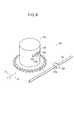
絶縁プレート134は樹脂製材料、例えば、PEEK(ポリエーテル・エーテル・ケトン樹脂)からなる円板状部材の一部をカット面134aによりカットした形状(部分円板状)であって、円弧の略中心にはシャフト110が挿通する孔134bが設けられ、上面には主軸部材128の筒体140及びブリッジ142aが係合する座繰り134cが設けられている。座繰り134cの深さは、前記ブリッジ142aの厚さと略同等である。 The insulating
筒体140、絶縁プレート134及び歯車体130は、シャフト110を軸として積層配置されており、その積層高さはHと略等しく、一対の舌片部58、58の間にほぼ隙間なく設けられている(図4参照)。 The
次に、駆動機構部102は、カバー150と、該カバー150内に収納される歯車リング152及び歯車体154と、これらを軸支する固定ピン(第2関節軸)156とを有する。 Next, the
歯車リング152は薄い筒体であって、Z2方向の面に設けられたフェイスギア158と、Z1方向の面に設けられたフェイスギア160とを有する。歯車リング152は主軸部材128の環状座面142に外挿され、該環状座面142の外周面に対して摺動回転自在である(図4参照)。フェイスギア158は第1歯車138に噛合し、歯車リング152は歯車体130の回転に伴って連結部16aの中心軸を中心として回転可能である。 The
カバー150は、駆動機構部102における各部品を保護及び支持するためのものであって、Z2方向の短筒162と、該短筒162のX2方向端部からZ1方向に向かって突出している耳片部164aと、短筒162のX1方向端部よりもやや内側(X2方向)からZ1方向に向かって突出し、前記耳片部164aと対向する耳片部164bとを有する。耳片部164aよりも耳片部164bの方が肉厚に構成される。また、各耳片部164a、164bには、固定ピン156が挿入される孔166が設けられている。固定ピン156は孔166に、例えば、圧入されて固定される。耳片部164a、164bの対向する面は平行に形成されており、歯車体154、係合片168及びピッチベース144を摺動自在に保持できる幅に設定されている。短筒162の内周面は歯車リング152の外周面よりやや大径に設定され、隙間が設けられている(図4参照)。なお、前記係合片168は、エンドエフェクタ104を構成する部品の一つである。 The
歯車体154は、耳片部164a、164bの間のX2方向に配置される部品であって、第2歯車170と、該第2歯車170と同心でX1側に設けられたDカット形状の突起172とを有する。第2歯車170は、フェイスギア160と噛合する。歯車体154には、中心部に固定ピン156が挿入される孔156aが設けられている。 The
次に、エンドエフェクタ104は、エンドエフェクタ部材174を有する。エンドエフェクタ部材174は、ブレード(電極部材)176と、係合片168とを有する。 Next, the
ブレード176は、長尺の薄板状部材であり、その基端部における幅方向(X方向)のX2側には、係合片168がZ2方向に向けて突設されている。 The
係合片168は、第2回転軸Opを中心軸とする短筒178と、該短筒178とブレード176とを連結するブリッジ179とを有する。短筒178には突起172が係合するDカット形状の孔178aが設けられている。 The engaging
歯車体154、係合片168及びピッチベース144は、耳片部164aと耳片部164bの間にほとんど隙間なく配置され、固定ピン156が孔156a及び孔144bに挿入され、軸支される(図5参照)。これにより、エンドエフェクタ部材174は、歯車リング152の回転作用下に、第2回転軸Opを中心として揺動自在となる。この際、歯車体154は歯車リング152の回転作用下に従動的に回転する。 The
すなわち、作業部12aでは、歯車体130の回転が第1歯車138から歯車リング152を介して歯車体154へと伝達され、これによりブレード176が第2回転軸Opを中心として俯仰可能となる。 In other words, in the working
なお、主軸部材128の筒体140にはワイヤ52が、歯車体130の筒体136にはワイヤ54が、それぞれ例えば1.5回以上巻き掛けられている(図4参照)。 It should be noted that the
次に、このように構成されるマニピュレータ10aの作用について説明する。なお、駆動機構は、機構的な干渉が存在するため、各駆動プーリ(各駆動モータ)の動作と各回転軸(姿勢軸)の動作は一対一に対応していないが、以下の説明では、簡単のため、代表的な駆動プーリ(各駆動モータ)の動作と各回転軸(姿勢軸)の動作を一対一に対応させて説明する。 Next, the operation of the
この場合、先ず、操作指令部14aのスイッチ37をONとして、マニピュレータ10aを駆動可能な状態とする。次いで、図7に示すように、ヨー方向の動作に関しては横ローラ(第1入力部)35(図1参照)を指で操作することにより行われる。すなわち、横ローラ35を指で左右に所定角度回転させるように操作することによりモータ40の回転作用下に駆動プーリ50aが回転してワイヤ52が駆動され、主軸部材128が第1回転軸Oyを中心として回転する。これにより、主軸部材128のピッチベース144に接続された駆動機構部102及びエンドエフェクタ104がヨー方向に揺動することになる。この際、主軸部材128のブリッジ142aが絶縁プレート134の座繰り134cに係合されているため、主軸部材128の回転に連動して、絶縁プレート134も回転する。 In this case, first, the
横ローラ35の左右(正逆)二方向への回転操作により、ヨー方向の動作は横ローラ35の回転方向に応じて左右(正逆)方向へ揺動する。また、横ローラ35を所定角度で停止させるとモータ40は停止し、ヨー方向の動作もその時点の位置を保持して停止する。 By rotating the
エンドエフェクタ104のピッチ方向の動作に関しては縦ローラ(第2入力部)34(図1参照)を指で操作することにより行われる。すなわち、縦ローラ34を指で上下に所定角度回転させるように操作することによりモータ42の回転作用下に駆動プーリ50bが回転してワイヤ54が駆動される。これにより、歯車体130が回転し、第1歯車138、フェイスギア158、160及び第2歯車170を介して歯車体154に回転が伝達される。歯車体154は突起172により係合片168と一体に第2回転軸Opを中心として俯仰することになる。つまり、ブレード176が第2回転軸Opを中心として俯仰される。 The movement of the
縦ローラ34の上下(正逆)ニ方向への回転操作により、エンドエフェクタ104はこの縦ローラ34の操作に連動し、すなわち、縦ローラ34の回転角度に応じてY1方向又はY2方向に俯仰される。また、縦ローラ34を所定角度で停止させるとモータ42は停止し、エンドエフェクタ104の回転位置を保持することができる。 By rotating the
ところで、マニピュレータ10aはモノポーラ電気メスとして使用されるが、この場合には、所定の電源180から端子182(図1参照)を介して、連結部16a、先端側接続部47、歯車体130、154、主軸部材128、ワイヤ52、54、歯車リング152、係合片168、シャフト110及び固定ピン156等の各構造部材及び各動力伝達部材を利用して、先端のブレード176へと通電することで、患部の処置を行うことが可能である。すなわち、電源180からの電流は、電源ケーブルを介して端子182からマニピュレータ10a内へと通電された後、エンドエフェクタ104から作業対象である人体へと通電され、その後、該人体に当接された電極プレートから電源ケーブルを介して前記電源180へと戻ることになる。なお、ブレード176は、上記のように、ヨー方向やピッチ方向に揺動自在であることから、所望の位置に容易にブレード176を介して通電、処置を行うことができる。 By the way, the
この際、生体組織と接触する外周部を有する連結部16a、先端側接続部47及びカバー150は動力伝達部材ではないため、絶縁材料や絶縁コーティング(被覆)を用いておくことができる。そうすると、仮に、連結部16a等が生体組織と接触した場合でも、該接触部を介して通電されることが回避できる。 At this time, since the connecting
一方、歯車体130や主軸部材128及びワイヤ52、54等は動力伝達部材であるため、絶縁材料や絶縁コーティングを用いることが困難である。また、これら動力伝達部材を全て絶縁材料とすると、電源180からブレード176への通電が不可能となる。 On the other hand, since the
そこで、作業部12aでは、絶縁プレート134により前記歯車体130や主軸部材128、ワイヤ52、54等が第1回転軸Oyを中心とする関節部から外部へと露出することを効果的に防止している。 Therefore, in the working
すなわち、図5及び図8に示すように、絶縁プレート134の円弧の半径が十分に大きく、例えば、短筒49の半径と同程度であると、前記関節部の第1歯車138、筒体136、140及びワイヤ52、54の露出が防止される。これにより、第1歯車138等と生体組織との距離が絶縁プレート134により保持され、該生体組織と第1歯車138等との接触を防止することができる。つまり、絶縁プレート134は、第1歯車138等と生体組織との接触を妨害する盾となり、該第1歯車138等から生体組織への不用意な通電を妨害する妨害部材として機能する。換言すると、絶縁プレート134は、生体組織と第1歯車138等の距離を保つ離間部材として機能する。 That is, as shown in FIGS. 5 and 8, when the radius of the arc of the insulating
この場合、図9に示すように、絶縁プレート134の円弧(円板)の半径の大きさ(r0)は、筒体140の半径(r1)とワイヤ52の直径(d)を加えた幅や、筒体136の半径とワイヤ54の直径を加えた幅よりも大きいものとすると、絶縁プレート134の外周を筒体140、136及びワイヤ52、54よりも確実に外側に位置させることができる。このため、前記生体組織と第1歯車138等の間の距離を適切に保持することができる。 In this case, as shown in FIG. 9, the radius (r0) of the arc (disk) of the insulating
これに対して、上記従来技術のように絶縁プレート134を持たない構成を考えてみると(図10参照)、関節部の第1歯車138、筒体136、140やワイヤ52、54が露出しているため、これらと生体組織とが接触し易い状態にある。つまり、一対の舌片部58、58の間から生体組織が関節部へと入り込み、第1歯車138等と接触する可能性が高いことになる。 On the other hand, when considering a configuration without the insulating
さらに、図11に示すように、駆動機構部102及びエンドエフェクタ104をヨー方向に略直角となるまで動作させ、第1回転軸Oyを中心とする関節部からの第1歯車138等の露出範囲が大幅に拡大された場合であっても、絶縁プレート134により前記関節部の開口部が有効に塞がれる。特に、作業部12aでは、上記のように、円弧を有する絶縁プレート134が主軸部材128と共に回転するように構成しているため、前記関節部を大きく屈曲させたとしても、絶縁プレート134が駆動機構部102等と共に回動する。従って、絶縁プレート134の円弧(円板)により、生体組織と第1歯車138等との距離を常に一定に保つことができる。つまり、作業部12aでは、エンドエフェクタ104の可動範囲や洗浄性を十分に確保しながら、第1回転軸Oyでのヨー方向の揺動動作に応じて、絶縁プレート134も揺動動作を行うため、生体組織と第1歯車138等との接触を防止し続けることができる。 Further, as shown in FIG. 11, the
なお、絶縁プレート134は、上記のように第1歯車138等と生体組織との不用意な接触(通電)を防止する観点から、その材質は、絶縁(非導電性)材料であることが好ましく、上記のように、PEEK等の樹脂製材料やジルコニア等を含むセラミックス材料が好ましい。ただし、高温による滅菌処理等を考慮した場合には、十分に高い熱変形温度(例えば、132℃以上)が必要である。さらに、作業部12aは体内で使用されるため、脆性破壊がなく、内視鏡の光で乱反射しない材質であることが好ましい。 The insulating
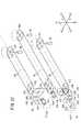
次に、第1の実施形態に係るマニピュレータ10aの変形例であるマニピュレータ10bについて、図12〜図16を参照しながら説明する。 Next, a
マニピュレータ10bは前記のマニピュレータ10aと比較して操作指令部14a及び連結部16aは共通であり、作業部12aを作業部12bに代えた構成となっている。作業部12bは、ワイヤ受動部200と、駆動機構部202と、エンドエフェクタ(作用部)204とを有する。 Compared with the
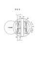
図12に示すように、作業部12bは、Y方向の第1回転軸Oyを中心にして、それよりも先の部分がヨー方向に回動する第1自由度と、Z方向の第2回転軸Orを中心にして、ロール方向に回動する第2自由度とを有する合計2自由度の機構となっている。 As shown in FIG. 12, the working
ワイヤ受動部200は、前記のワイヤ受動部100に相当する部分であり、該ワイヤ受動部100と比較して、主軸部材128の代わりに主軸部材206を有している。主軸部材206は、主軸部材128のピッチベース144を主軸(第2関節軸)208に代えた構成である。主軸208は、環状座面142からZ1方向に突設されている。 The wire
ワイヤ受動部200は、前記のワイヤ受動部100と同様に、筒体140及び筒体136に対して、ワイヤ52及びワイヤ54が巻き掛けられている。ワイヤ受動部200では、主軸部材206(主軸208)を第1回転軸Oyを中心としてヨー方向に揺動させることができる。 In the wire
次に、駆動機構部202は、クラウン210と、カバー212とを有する。 Next, the
クラウン210は、薄い筒体214と、該筒体214のZ2方向の面に設けられたフェイスギア216と、筒体214のZ1方向の面を塞ぐ円板218と、該円板218の中心からZ1方向に突出するDカット形状の突起220とを有する。円板218及び突起220には主軸208が挿入される孔210aが設けられている。フェイスギア216は、第1歯車138に噛合する。 The
カバー212は、先端側接続部47と略同等な外径からなり、前記筒体214が内挿される筒体222と、突起220が挿入される孔212aと、該孔212aからY2方向に形成される長孔212bとを有する。筒体222の内周面はクラウン210の外周面よりやや大径に設定され、隙間が設けられている(図14参照)。カバー212には、前記カバー150等と同様、絶縁材料や絶縁コーティング(被覆)が用いられている。 The
次に、エンドエフェクタ204は、フック(電極部材)224と、固定ナット226とを有する。 Next, the
フック224は、駆動機構部202と連結される接続部228と、第2回転軸Orからややずれた位置において接続部228の下方からZ1方向に延在するアーム230と、該アーム230の先端がY1方向に屈曲した電極232とを有する。接続部228にはクラウン210の突起220が挿入されるDカット形状の孔224aが設けられている。 The
固定ナット226は、主軸208がクラウン210、カバー212及びフック224に挿入された状態で、これらを一体に固定するものである。固定ナット226には、細い回転工具を挿入するための径方向の複数の細孔226aが設けられている。従って、フック224の接続部228及びアーム230をカバー212の孔212a及び長孔212bへと挿入し、さらに、孔224aに突起220を挿入した上で、クラウン210の孔210aに対して主軸208を挿入すると、該主軸208の先端部が接続部228よりもZ1方向に突出する。この突出した部分に固定ナット226を装着、固定することによりエンドエフェクタ204は駆動機構部202に対して組み立てられ、クラウン210、カバー212及びフック224は主軸208を中心として回動自在に軸支される。 The fixing
このようなエンドエフェクタ204では、歯車体130及び第1歯車138の回転作用下に、クラウン210及びフック224が第2回転軸Orを中心として回転可能となる。 In such an
次に、このように構成されるマニピュレータ10bの作用について図16を参照しながら説明する。 Next, the operation of the
この場合、先ず、操作指令部14aのスイッチ37をONとして、マニピュレータ10bを駆動可能な状態とする。次いで、図16に示すように、ヨー方向の動作に関しては横ローラ35(図1参照)を指で操作することにより行われる。すなわち、横ローラ35を指で左右に所定角度回転させるように操作することによりモータ40の回転作用下に駆動プーリ50aが回転してワイヤ52が駆動され、主軸部材206が第1回転軸Oyを中心として回転する。これにより、主軸部材206の主軸208に接続された駆動機構部202及びエンドエフェクタ204がヨー方向に揺動することになる。この際、前記の作業部12aの場合と同様に、主軸部材206のブリッジ142aが絶縁プレート134の座繰り134cに係合されているため、主軸部材206の回転に連動して、絶縁プレート134も回転する。 In this case, first, the
エンドエフェクタ204のロール方向の動作に関しては縦ローラ34(図1参照)を指で引き寄せることにより行われる。すなわち、縦ローラ34を指で上下に所定角度回転させるように操作することによりモータ42の回転作用下に駆動プーリ50bが回転してワイヤ54が駆動される。これにより、歯車体130が回転し、第1歯車138を介して、フェイスギア216に回転が伝達されて、エンドエフェクタ204のフック224はクラウン210の突起220と共に第2回転軸Opを中心として回転することになる。 The operation of the
このように構成されるマニピュレータ10bは、マニピュレータ10aと同様に、電源180から端子182(図1参照)を介して、連結部16a、先端側接続部47、歯車体130、主軸部材206、ワイヤ52、54、クラウン210、接続部228及びシャフト110等の各構造部材及び各動力伝達部材を利用して、先端のフック224へと通電することで、患部の処置を行うことが可能である。フック224は、上記のように、ヨー方向やロール方向に揺動及び回転自在であることから、所望の位置にフック224を介して通電、処置することができる。 Similarly to the
また、マニピュレータ10bにおいても、前記のマニピュレータ10aと同様に、絶縁プレート134を有している。このため、第1回転軸Oyを中心とする関節部での生体組織と歯車体130、主軸部材206及びワイヤ52、54との間の接触を効果的に防止することができる。特に、エンドエフェクタ204が第1回転軸Oyを中心としてヨー方向に大きく屈曲、例えば、略直角まで屈曲された場合でも、絶縁プレート134が前記関節部での開口部を塞ぐように、主軸部材206と共に回動する。これにより、エンドエフェクタ204の可動範囲や洗浄性を十分に確保しながら、絶縁プレート134により、歯車体130等と生体組織との間の接触を防止し続けることができる。 The
さらに、マニピュレータ10bでは、クラウン210の外周面も上記のように絶縁材料や絶縁コーティングが用いられたカバー212で保護されている。このため、該クラウン210と生体組織との接触も防止することができる。 Further, in the
次に、第2の実施形態に係るマニピュレータ10cについて、図17〜図21を参照しながら説明する。 Next, a
マニピュレータ10cは前記のマニピュレータ10aと比較して連結部16a及び操作指令部14aを、連結部16b及び操作指令部(操作部)14bに代え、作業部12aを作業部12cに代えた構成となっている。 Compared with the
操作指令部14bにおいて、アクチュエータブロック30には、作業部12cが有する3自由度の機構に対応して、モータ42と並列してモータ44が設けられている。 In the
連結部16bの基端側接続部46には、モータ44の駆動軸に接続される駆動プーリ(第3回転源)50cが駆動プーリ50bと並列に設けられている。駆動プーリ50cにはワイヤ(第3可撓性動力伝達部材)56が巻き掛けられており、ワイヤ52、54と同様に、連結シャフト48の中空部分48aを通って、作業部12cまで延在している。ワイヤ56は、ワイヤ52、54と同種、同径のものが用いられている。なお、連結部16bも前記の連結部16aと同様に、操作指令部14bから離脱可能である。 A drive pulley (third rotation source) 50c connected to the drive shaft of the
作業部12cは、ワイヤ受動部300と、駆動機構部302と、エンドエフェクタ(作用部)304とを有する。図18に示すように、作業部12cは、Y方向の第1回転軸Oyを中心にして、それよりも先の部分がヨー方向に回動する第1自由度と、X方向の第2回転軸Opを中心として先端のエンドエフェクタ304をピッチ方向に回動する第2自由度と、Z方向の第3回転軸Orを中心にして、ロール方向に回動する第3自由度とを有する合計3自由度の機構となっている。 The working
ワイヤ受動部300は、前記のワイヤ受動部100に相当する部分であり、Y1方向からY2方向に向かって順に、シャフト110に対して回転自在に軸支される歯車体130と、主軸部材306と、歯車体308とを有する。シャフト110の先端には雄ねじが設けてあり、雌ねじが設けてあるY1方向の軸孔60に螺着して固定される。 The wire
歯車体130は、ワイヤ受動部100の場合と比較して、連結シャフト48の中心軸を中心に反転して配置されている。つまり、筒体136の上部に第1歯車138が設けられていることになる。 Compared with the case of the wire
歯車体308は、筒体(第3筒体)310と、該筒体310の下部に同心状に設けられた第3歯車312とを有する。第3歯車312の下面には、シャフト110が挿入される孔の周辺に低い環状リブ310aが設けられており、第3歯車312の下面が下側の舌片部58に接触することが防止され摺動抵抗の低減を図っている(図20参照)。筒体310のZ2方向の側の面には、筒体136と同様のワイヤ固定機構120が設けられており、ワイヤ56を固定している。 The
歯車体130及び308の間に設けられた主軸部材306は、前記の主軸部材128に相当し、シャフト110が挿通する筒体313と、やや厚い環状座面314と、該環状座面314の中心からZ1方向に延在するピッチベース316とを有する。ピッチベース316は、前記のピッチベース144と同様、ピッチ動作の基準となる部材であって、ピッチ動作のための平行な左右一対の摺動面316aと、先端に設けられた回転中心となる孔316bとを有する。 The
環状座面314は上下2つの短いブリッジ314aを介して、筒体313の外側面よりもやや離れた位置に設けられており、環状座面314と筒体313との間にはワイヤ52が挿通可能で、Y方向にやや長い縦孔318が設けられている(図20参照)。筒体313のZ2方向の側には、筒体140と同様のワイヤ固定機構120が設けられており、ワイヤ52を固定している。 The
ワイヤ受動部300では、筒体313、筒体136及び筒体310に対して、ワイヤ52、ワイヤ54及びワイヤ56が巻き掛けられている。このようなワイヤ受動部300は、主軸部材306を第1回転軸Oyを中心としてヨー方向に揺動させることができる。 In the wire
さらに、ワイヤ受動部300は、筒体136と筒体313との間、及び筒体313と筒体310との間のシャフト110に対してそれぞれ回転自在に軸支される2枚の絶縁プレート(第1絶縁部材、第2絶縁部材)319、319を有する。 Furthermore, the wire
絶縁プレート319は、前記の絶縁プレート134に相当し、該絶縁プレート134よりも薄い円板部材の一部をカット面319aによりカットした形状からなり、円弧の略中心にはシャフト110が挿通する孔319bが設けられる。筒体313のY1方向に配置される絶縁プレート319の上面には、筒体136が当接する座繰り319cが形成される。同様に、筒体313のY2側に配置される絶縁プレート319の下面には、筒体310が当接する座繰り319cが形成される。これら座繰り319cの深さは、絶縁プレート319の厚さの半分程度である。 The insulating
絶縁プレート319の円弧(円板)の半径は、前記の絶縁プレート134の場合と同様に、筒体136の半径とワイヤ54の直径を加えた幅や、筒体313の半径とワイヤ52の直径を加えた幅や、筒体310の半径とワイヤ56の直径を加えた幅以上のものが好ましい。特に、絶縁プレート319の円弧(円板)の半径が、筒体136、313又は310のうちの最大の半径と、ワイヤ52、54又は56のうちの最大の直径との和以上であると、絶縁プレート319の外周を筒体136、313、310及びワイヤ52、54、56よりも確実に外側に位置させることができる。従って、前記生体組織と第1歯車138等の間の距離を適切に保持することができるため一層好ましい。なお、絶縁プレート319の材質は、前記の絶縁プレート134と同じものとすればよい。 As in the case of the insulating
このようにワイヤ受動部300では、一対の舌片部58、58の間の略中央部に筒体313が設けられ、その上下に筒体136及び310が設けられているため、2枚の薄い絶縁プレート319を用いることで、主軸部材306や第1歯車138、第3歯車312、ワイヤ52、54、56等の動力伝達部材が関節部の外部に露出することを効果的に防止している。 Thus, in the wire
次に、駆動機構部302は、カバー322と、該カバー322内に収納される歯車リング152、歯車リング320、歯車体324及び歯車体326と、エンドエフェクタ主軸部材328と、これらを軸支する固定ピン(第2関節軸)330とを有する。 Next, the
歯車リング320は薄い筒体であって、Z2方向の面に設けられたフェイスギア332と、Z1方向の面に設けられたフェイスギア334とを有する。歯車リング320は歯車リング152に内挿され、該歯車リング152の内周面に対して摺動回転自在となる。フェイスギア332は第3歯車312に噛合し、歯車リング320は歯車体308の回転に伴って第3回転軸Orを中心として回転可能である。 The
カバー322は、前記のカバー150に相当し、駆動機構部302における各部品を保護及び支持するためのものであって、Z2方向の短筒336と、該短筒336の左右両端からZ1方向に向かって突出している一対の耳片部338とを有する。各耳片部338には、固定ピン330が挿入され固定するための孔338aが設けられている。孔338aに対して、固定ピン330は、例えば圧入され固定される。耳片部338の対向する面は平行に形成されており、歯車体324、326、エンドエフェクタ主軸部材328の係合片340及びピッチベース316を摺動自在に保持する幅に設定されている。短筒336の内周面は歯車リング152の外周面よりやや大径に設定され、隙間が設けられている(図20参照)。カバー322には、前記カバー150等と同様、絶縁材料や絶縁コーティング(被覆)が用いられている。 The
歯車体324は、一対の耳片部338の間におけるX2方向に配置される部品であって、筒体342と、該筒体342の一方に同心状に設けられた第4歯車344と、筒体342の他方に同心状に設けられたDカット形状の突起346と、筒体342のZ1方向に設けられた支持台348とを有する。歯車体324は、第4歯車344がX2方向となるように配置され、該第4歯車344はフェイスギア160と噛合する。歯車体324には、中心部に固定ピン330が挿入される孔324aが設けられている。 The
エンドエフェクタ主軸部材328は、ベースの円板350と、該円板350からZ1方向に突出する主軸(第3関節軸)352と、円板350のZ2方向の面においてX2方向にややずれた位置からZ2方向に突出する係合片340とを有する。係合片340には突起346が係合するDカット形状の孔340aが設けられている。エンドエフェクタ主軸部材328は、孔340aに突起346が挿入されることによって、円板350と支持台348が面接触し、一体的且つ安定に組み立てられる。 The end effector
歯車体326は、一対の耳片部338の間におけるX1方向に配置される部品であって、筒体353と、該筒体353の一方に同心状に設けられた第5歯車354とを有する。歯車体326は、第5歯車354がX1方向となるように配置され、該第5歯車354は歯車リング320のフェイスギア334と噛合する。歯車体326には、中心部に固定ピン330が挿入される孔326aが設けられている。 The
歯車体326、エンドエフェクタ主軸部材328、ピッチベース316及び歯車体324の組立体は一対の耳片部338の間にほとんど隙間なく配置され、固定ピン330が孔324a、孔316b及び孔326aに挿入され、軸支される(図21参照)。これによりエンドエフェクタ主軸部材328と歯車体324との組立体は、歯車リング152の回転作用下に、第2回転軸Opを中心として揺動自在となる。また、歯車体326は歯車リング320の回転作用下に従動的に回転する。 The assembly of the
このような駆動機構部302では、歯車体130及び第1歯車138の回転が、歯車リング152及び第4歯車344を介して主軸352に伝達され、該主軸352が第2回転軸Opを中心として俯仰可能となる。また、歯車体308及び第3歯車312の回転が、歯車リング320を介して歯車体326及び第5歯車354に伝達される。 In such a
次に、エンドエフェクタ304は、クラウン210と、フック(電極部材)224と、固定ナット226とを有する。 Next, the
このようなエンドエフェクタ304では、孔224aに突起220を挿入した上で、クラウン210の孔210aに対して駆動機構部302の主軸352を挿入すると、該主軸352の先端部はフック224の接続部228よりもZ1方向に突出する。この突出した部分に固定ナット226を螺着することによりエンドエフェクタ304は駆動機構部302に対して組み立てられ、クラウン210及びフック224は主軸352を中心として回動自在に軸支される。また、フェイスギア216は第5歯車354に噛合する。すなわち、エンドエフェクタ304では、歯車体326及び第5歯車354の回転作用下に、クラウン210及びフック224が第3回転軸Orを中心として回転可能となる。 In such an
次に、このように構成されるマニピュレータ10cの作用について説明する。 Next, the operation of the
この場合、先ず、操作指令部14bのスイッチ37をONとして、マニピュレータ10cを駆動可能な状態とする。次いで、図22に示すように、ヨー方向の動作に関しては横ローラ35(図1参照)を指で操作することにより行われる。すなわち、横ローラ35を指で左右に所定角度回転させるように操作することによりモータ40の回転作用下に駆動プーリ50aが回転してワイヤ52が駆動され、主軸部材306が第1回転軸Oyを中心として回転する。これにより、主軸部材306のピッチベース316に接続された駆動機構部302及びエンドエフェクタ304がヨー方向に揺動することになる。この際、作業部12a等の場合と同様に、主軸部材306の回転に連動して、2枚の絶縁プレート319も回転する。 In this case, first, the
ピッチ方向の動作は縦ローラ34(図1参照)を指で操作することにより行われる。すなわち、縦ローラ34を指で上下に所定角度回転させるように操作することによりモータ42の回転作用下に駆動プーリ50bが回転してワイヤ54が駆動される。これにより、歯車体130が回転し、第1歯車138、フェイスギア158、160及び第4歯車344を介して歯車体324に回転が伝達される。歯車体324は突起346により係合片340と一体的に第2回転軸Opを中心として俯仰することになる。つまり、係合片340から主軸352を介してフック224が第2回転軸Opを中心として俯仰される。 The operation in the pitch direction is performed by operating the vertical roller 34 (see FIG. 1) with a finger. That is, by operating the
エンドエフェクタ304のロール方向の動作に関してはトリガーレバー(第3入力部)32(図1参照)を指で引き寄せることにより行われる。すなわち、トリガーレバー32を指で引き寄せることによりモータ44の回転作用下に駆動プーリ50cが回転することによってワイヤ56が駆動される。これにより、歯車体308が回転し、第3歯車312、フェイスギア332、334及び第5歯車354を介してフェイスギア216に回転が伝達され、エンドエフェクタ204のフック224はクラウン210の突起220と共に第3回転軸Opを中心として回転することになる。 The operation of the
トリガーレバー32は指による引き寄せが可能であり、指を離すことにより弾性体によって元の位置に復帰する。エンドエフェクタ304はこのトリガーレバー32の操作に連動し、トリガーレバー32の引き寄せの程度に応じてロール方向に回転される。この場合、トリガーレバー32を元の位置に戻せば、エンドエフェクタ304のロール方向回転位置も中立位置へと戻される。 The trigger lever 32 can be pulled by a finger and returns to its original position by an elastic body when the finger is released. The
なお、このような3自由度の機構からなるマニピュレータ10cでは、前記トリガーレバー32を切換スイッチとして機能させてもよい。この場合、例えば、前記切換スイッチであるトリガーレバー32を切換操作することにより、例えば、ピッチ方向の動作を操作する縦ローラ34を、選択的にエンドエフェクタ304のロール方向の動作のための操作手段としても用いることができる。さらに、前記エンドエフェクタ304のように3自由度の機構において最先端の姿勢軸は、他の操作デバイスを別途用意して操作するようにしてもよい。 In the
このように構成されるマニピュレータ10cは、マニピュレータ10a等と同様に、電源180から端子182を介して、連結部16b、先端側接続部47、歯車体130、308、324、326、主軸部材306、ワイヤ52、54、56、歯車リング152、320、エンドエフェクタ主軸部材328、クラウン210、接続部228、シャフト110及び固定ピン330等の各構造部材及び各動力伝達部材を利用して、先端のフック224へと通電することで、患部の処置を行うことが可能である。フック224は、上記のように、ヨー方向やピッチ方向やロール方向に揺動及び回転自在であることから、所望の位置にフック224を介して通電、処置することができる。 Like the
また、マニピュレータ10cにおいても、前記のマニピュレータ10a等の絶縁プレート134に相当する2枚の絶縁プレート319を有している。このため、図23に示すように、第1回転軸Oyを中心とする関節部での生体組織と歯車体130、308、主軸部材306及びワイヤ52、54、56との間の接触を防止することができる。特に、エンドエフェクタ304が第1回転軸Oyを中心としてヨー方向に大きく屈曲、例えば、略直角まで屈曲された場合でも、2枚の絶縁プレート319が前記関節部での開口部を塞ぐように、主軸部材306と共に回動する。これにより、エンドエフェクタ304の可動範囲や洗浄性を十分に確保しながら、絶縁プレート319により、歯車体130等と生体組織との間での接触を防止し続けることができる。 The
なお、マニピュレータ10cのワイヤ受動部300では、一対の舌片部58、58の間の略中央部に筒体313が設けられ、その上下に筒体136及び310が設けられているが、上記のように2枚の薄い絶縁プレート319を用いることで、該絶縁プレート319を関節部の開口部に均等に配置させ、第1歯車138、第3歯車312やワイヤ52、54、56等の動力伝達部材が関節部の外部に露出して生体組織と接触することを効果的に防止している。 In the wire
次に、第2の実施形態に係るマニピュレータ10cの変形例であるマニピュレータ10dについて、図24及び図25を参照しながら説明する。 Next, a
マニピュレータ10dは前記のマニピュレータ10cと比較して操作指令部14b及び連結部16bは共通であり、作業部12cを作業部12dに代えた構成となっている。作業部12dは、ワイヤ受動部300と、駆動機構部402と、エンドエフェクタ(作用部)404とを有する。 Compared to the
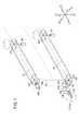
図24に示すように、作業部12dは、Y方向の第1回転軸(第1関節軸)Oyを中心にして、それよりも先の部分がヨー方向に回動する第1自由度と、Z方向の第2回転軸(第2関節軸)Opを中心にして先端のエンドエフェクタ404をピッチ方向に回動する第2自由度と、Z方向の前記第2回転軸Opと同軸の第3回転軸(第3関節軸、グリッパ軸)Ogを中心として先端のエンドエフェクタ404を開閉させる第3自由度とを有する合計3自由度の機構となっている。 As shown in FIG. 24, the working
駆動機構部402は、カバー322と、該カバー322内に収納される歯車リング152、320、歯車体406及び歯車体408と、これらを軸支する固定ピン330とを有する。 The
歯車体406は、一対の耳片部338の間におけるX2方向に配置される部品であって、第6歯車410と、該第6歯車410と同心にX1側に設けられたDカット形状の突起412とを有する。第6歯車410は、フェイスギア160と噛合する。歯車体406には、中心部に固定ピン330が挿入される孔406aが設けられている。 The
歯車体408は、一対の耳片部338の間におけるX1方向に配置される部品であって、第7歯車414と、該第7歯車414と同心にX2側に設けられたDカット形状の突起416とを有する。第7歯車414は、フェイスギア334と噛合する。歯車体408には、中心部に固定ピン330が挿入される孔408aが設けられている。 The
次に、エンドエフェクタ404は、第1エンドエフェクタ部材418と、第2エンドエフェクタ部材420とを有する。 Next, the
第1エンドエフェクタ部材418は、基端筒422と、該基端筒422から略径方向(Z1方向)に突出するアーム424と、該アーム424からさらに径方向(Z1方向)に向けて突出するグリッパ426とを有する。基端筒422の中心には突起412が係合するのに適したDカット形状の孔422aが設けられており、該突起412に対する位置決め機能及び回り止め機能を有する。 The first
グリッパ426は、基端筒422及びアーム424よりもやや幅方向(X1方向)に厚く、グリッパ426の幅方向中間部が基端筒422及びアーム424のX1方向端面に略等しい。グリッパ426は、両端円弧状で内側面426aにはX方向に延在する筋が全面に設けられており(図24及び図25の第2エンドエフェクタ420におけるグリッパ428の内側面428aと同様)、把持するツール等の滑り止めとなる。グリッパ426には、軽量化や前記ツール等の把持性向上のための長孔426bが設けられている。 The
第2エンドエフェクタ部材420は、第1エンドエフェクタ部材418と同形状であり、グリッパ426と同形状のグリッパ428を有する。第2エンドエフェクタ部材420は、歯車体408の突起416に係合し、第1エンドエフェクタ部材418に対して上下反転した向きに配置されるものである。なお、第2エンドエフェクタ部材420の各部については、第1エンドエフェクタ部材418と同符号を付して詳細な説明を省略する。 The second
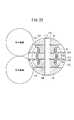
第1エンドエフェクタ部材418のグリッパ426はX1方向寄りに配置され、第2エンドエフェクタ部材420のグリッパ428はX2方向寄りに配置され、グリッパ426及び428は、それぞれの内側面426aが対面するように連結シャフト48の中心軸(図25の基準軸C)を中心として対称配置される。 The
第6歯車410及び第7歯車414と、2つの基端筒と、ピッチベース316とは、一対の耳片部338の間にほとんど隙間なく配置され(図24参照)、固定ピン330が孔406a、孔316b及び孔408aに挿入され、軸支される。 The
このようなエンドエフェクタ404において、第1エンドエフェクタ部材418は、歯車リング152の回転が第6歯車410に伝達されることで、第2回転軸Op(第3回転軸Og)を中心として揺動自在となる。また、第2エンドエフェクタ部材420は、歯車リング320の回転が第7歯車414に伝達されることで、第2回転軸Op(第3回転軸Og)を中心として揺動自在となる。 In such an
つまり、正面から見て(基準軸CのZ1方向からZ2方向を見て)歯車リング152及び320が共に時計方向に回転するときには、第6歯車410は基準軸Cからの側面視で反時計方向に回転し、第7歯車414は基準軸Cからの側面視で反時計方向に回転する。これにより、一対のアーム424、424及び一対のグリッパ426、428は、それぞれが接近する方向(閉じる方向)に動作する。一方、正面から見て歯車リング152及び320が共に反時計方向に回転するときには、第6歯車410は基準軸Cからの側面視で時計方向に回転し、第7歯車414は基準軸Cからの側面視で時計方向に回転する。これにより、一対のアーム424、424及び一対のグリッパ426、428は、それぞれが離間する方向(開く方向)に動作する。 That is, when the gear rings 152 and 320 rotate clockwise when viewed from the front (when viewed from the Z1 direction of the reference axis C to the Z2 direction), the
このようにエンドエフェクタ404では、縦ローラ34及びトリガーレバー32を操作することで、歯車体130及び308が回転し、これらの回転が歯車リング152及び320を介して、第6歯車410及び第7歯車414に伝達され、第3回転軸Og(グリッパ軸)を中心とした一対のグリッパ426、428の開閉動作を行うことができる。 As described above, in the
さらに、縦ローラ34及びトリガーレバー32を操作して、歯車リング152及び320を互いに逆方向に回転させることで、一対のグリッパ426、428の揺動方向を同一方向とすることができる。つまり、一対のグリッパ426、428は、第2回転軸Opを中心としてピッチ方向に俯仰することになる。なお、縦ローラ34及びトリガーレバー32を個別に操作して、各グリッパ426、428を個別にピッチ方向に俯仰させることが可能であるのは言うまでもない。また、ヨー方向への動作は、前記の作業部12cの場合と同様であるため、詳細な説明は省略する。 Further, by operating the
このように構成されるマニピュレータ10dは、マニピュレータ10cと同様に、電源180から端子182(図1参照)を介して、連結部16b、先端側接続部47、歯車体130、308、406、408、主軸部材306、ワイヤ52、54、56、歯車リング152、320、第1エンドエフェクタ部材418、第2エンドエフェクタ部材420、シャフト110及び固定ピン330等の各構造部材及び各動力伝達部材を利用して、先端のグリッパ426、428へと通電することで、患部の処置を行うことが可能である。グリッパ426、428は、上記のように、ヨー方向やピッチ方向に揺動及び回転自在且つ開閉自在であることから、所望のツール等を把持して、所望の位置に容易にグリッパ426、428を介して通電、処置することができる。 Similarly to the
また、マニピュレータ10dにおいても、前記のマニピュレータ10cと同様、2枚の絶縁プレート319を有している。このため、第1回転軸Oyを中心とする関節部での生体組織と歯車体130、308、主軸部材306及びワイヤ52、54、56との間の接触を防止することができる。特に、エンドエフェクタ404が第1回転軸Oyを中心としてヨー方向に大きく屈曲、例えば、略直角まで屈曲された場合でも、2枚の絶縁プレート319が前記関節部での開口部を塞ぐように、主軸部材306と共に回動する。すなわち、エンドエフェクタ404の可動範囲や洗浄性を十分に確保しながら、絶縁プレート319により、前記歯車体130等と生体組織との間での接触を防止し続けることができる。 Further, the
なお、マニピュレータ10a〜10d及び作業部12a〜12dは医療用、すなわち作業対象、作業環境が生体であるものとして説明したが、使用用途はこれに限らず、マニピュレータ10a〜10dと作業対象、作業環境とで絶縁性が要求されるものであれば適用可能である。 Although the
また、作業部12a、12bのエンドエフェクタ104、204を、作業部12dのグリッパ426、428のようなものに変更可能であることは言うまでもなく、これらグリッパ426、428の形状、構成を変えることにより鋏、ペンチ、ニッパ、エンドニッパ等を構成可能であることは容易に理解されよう。 Needless to say, the
各実施形態における平歯車とフェイスギアとの組合わせは、相互に接触して回転の向きを変えて動力を伝達することのできるものであればよく、例えば、傘歯車対であってもよい。 The combination of the spur gear and the face gear in each embodiment may be any combination that can contact each other and change the direction of rotation to transmit power, and may be a bevel gear pair, for example.
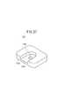
また、絶縁プレート134、319は、作業対象(例えば、生体組織)と動力伝達部材(歯車体138等)との間の接触を防ぐことができればよいものであり、例えば、その形状は、上記のような部分円板状以外にも、円弧が2重に形成されているものや矩形のもの等が挙げられる。すなわち、例えば、前記絶縁プレート134と交換可能な絶縁プレートとして、略卵型の絶縁プレート135(図26参照)や、角丸四角型の絶縁プレート137(図27参照)等が挙げられる。例えば、前記絶縁プレート135を前記作業部12aに適用すると、ヨー方向への揺動角度が増えるに伴って、その外部への突出量(突出径)を増大させることができる(図28参照)。また、例えば、前記絶縁プレート137を前記作業部12aに適用すると、ヨー方向への揺動角度が略直角となった場合に、該絶縁プレート137がその対角線方向である45°方向となり、最大の突出量(突出径)とすることができる。 The insulating
本発明に係る作業機構及びマニピュレータは、上記の実施形態に限らず、本発明の要旨を逸脱することなく、種々の構成を採り得ることはもちろんである。 Of course, the working mechanism and the manipulator according to the present invention are not limited to the above-described embodiments, and various configurations can be adopted without departing from the gist of the present invention.
10a〜10d…マニピュレータ 12a〜12d…作業部
14a、14b…操作指令部 16a、16b…連結部
32…トリガーレバー 34…縦ローラ
35…横ローラ 37…スイッチ
50a〜50c…駆動プーリ 52、54、56…ワイヤ
100、200、300…ワイヤ受動部
102、202、302、402…駆動機構部
104、204、304、404…エンドエフェクタ
110…シャフト 128、206、306…主軸部材
130、154、308、324、326、406、408…歯車体
134、135、137、319…絶縁プレート
136、140、222、310、313、342、353…筒体
138、170、312、344、354、410、414…歯車
152、320…歯車リング 156、330…固定ピン
158、160、216、332、334…フェイスギア
174、418、420…エンドエフェクタ部材
176…ブレード 224…フック
328…エンドエフェクタ主軸部材 426、428…グリッパ10a to 10d ...
Claims (7)
Translated fromJapanese前記操作部に設けられた第1入力部及び第2入力部と、
前記第1入力部及び第2入力部の操作に基づいて回転する第1回転源及び第2回転源と、
尾端側が前記操作部、又は、前記第1回転源及び第2回転源を回転駆動する駆動部に連結された連結部と、
前記連結部の先端側に設けられた第1関節軸と、
前記第1関節軸と交差する第2関節軸と、
前記第1関節軸に軸支された第1筒体及び第2筒体と、
後方部が前記第1回転源に巻き掛けられ、前方部が前記第1筒体に巻き掛けられた第1可撓性動力伝達部材と、
後方部が前記第2回転源に巻き掛けられ、前方部が前記第2筒体に巻き掛けられた第2可撓性動力伝達部材と、
前記第1筒体の回転に連動し、前記第1関節軸を中心として動作する駆動機構部と、
前記駆動機構部の前方に設けられ、前記第2筒体の回転に連動し、前記第2関節軸を中心として動作する作用部と、
前記第1関節軸に軸支された第1絶縁部材と、
を有することを特徴とするマニピュレータ。An operation unit;
A first input unit and a second input unit provided in the operation unit;
A first rotation source and a second rotation source that rotate based on operations of the first input unit and the second input unit;
A connecting portion in which the tail end side is connected to the operation unit or a driving unit that rotationally drives the first rotation source and the second rotation source;
A first joint shaft provided on the distal end side of the connecting portion;
A second joint axis that intersects the first joint axis;
A first cylinder and a second cylinder supported by the first joint shaft;
A first flexible power transmission member having a rear part wound around the first rotation source and a front part wound around the first cylinder;
A second flexible power transmission member having a rear part wound around the second rotation source and a front part wound around the second cylinder;
A drive mechanism that operates around the first joint axis in conjunction with the rotation of the first cylinder;
An action part provided in front of the drive mechanism part, interlocking with the rotation of the second cylindrical body, and operating around the second joint axis;
A first insulating member pivotally supported on the first joint shaft;
A manipulator characterized by comprising:
前記第1絶縁部材は、前記第1筒体と前記第2筒体との間に配設されていることを特徴とするマニピュレータ。The manipulator according to claim 1, wherein
The manipulator, wherein the first insulating member is disposed between the first cylinder and the second cylinder.
前記第1絶縁部材の少なくとも一部は円板状に形成され、該円板の半径は、前記第1筒体の半径と前記第1可撓性動力伝達部材の直径の和以上であり、且つ、前記第2筒体の半径と前記第2可撓性動力伝達部材の直径の和以上であることを特徴とするマニピュレータ。The manipulator according to claim 1 or 2,
At least a part of the first insulating member is formed in a disc shape, and the radius of the disc is equal to or greater than the sum of the radius of the first cylindrical body and the diameter of the first flexible power transmission member, and A manipulator characterized in that it is equal to or greater than the sum of the radius of the second cylinder and the diameter of the second flexible power transmission member.
前記操作部には第3入力部が設けられ、
さらに、前記第3入力部の操作に基づいて回転する第3回転源と、
前記第2関節軸と直交又は同軸に設けられた第3関節軸と、
前記第1関節軸に軸支された第3筒体と、
後方部が前記第3回転源に巻き掛けられ、前方部が前記第3筒体に巻き掛けられた第3可撓性動力伝達部材と、
前記第1関節軸に軸支された第2絶縁部材と、
を有し、
前記作用部は、前記第3筒体の回転に連動し、前記第3関節軸を中心として動作することを特徴とするマニピュレータ。The manipulator according to claim 1, wherein
The operation unit is provided with a third input unit,
A third rotation source that rotates based on an operation of the third input unit;
A third joint axis provided orthogonal or coaxial with the second joint axis;
A third cylinder pivotally supported by the first joint shaft;
A third flexible power transmission member having a rear part wound around the third rotation source and a front part wound around the third cylinder;
A second insulating member pivotally supported on the first joint shaft;
Have
The manipulator is characterized in that the action section operates around the third joint axis in conjunction with the rotation of the third cylinder.
前記第1筒体は、前記第2筒体と前記第3筒体との間に配設され、
前記第1絶縁部材は、前記第1筒体と前記第2筒体との間に配設され、
前記第2絶縁部材は、前記第1筒体と前記第3筒体との間に配設されていることを特徴とするマニピュレータ。The manipulator according to claim 4, wherein
The first cylinder is disposed between the second cylinder and the third cylinder,
The first insulating member is disposed between the first cylinder and the second cylinder,
The manipulator, wherein the second insulating member is disposed between the first cylinder and the third cylinder.
前記第1絶縁部材及び前記第2絶縁部材の少なくとも一部は円板状に形成され、該円板の半径は、前記第1筒体、前記第2筒体又は前記第3筒体のうちの最大の半径と、前記第1可撓性動力伝達部材、第2可撓性動力伝達部材又は第3可撓性動力伝達部材のうちの最大の直径との和以上であることを特徴とするマニピュレータ。The manipulator according to claim 4 or 5,
At least a part of the first insulating member and the second insulating member is formed in a disc shape, and the radius of the disc is equal to that of the first cylindrical body, the second cylindrical body, or the third cylindrical body. A manipulator characterized in that it is equal to or greater than the sum of the maximum radius and the maximum diameter of the first flexible power transmission member, the second flexible power transmission member, or the third flexible power transmission member. .
前記第1絶縁部材及び前記第2絶縁部材は、前記第1筒体の回転に連動して回転することを特徴とするマニピュレータ。The manipulator according to any one of claims 1 to 6,
The manipulator, wherein the first insulating member and the second insulating member rotate in conjunction with the rotation of the first cylinder.
Priority Applications (5)
| Application Number | Priority Date | Filing Date | Title |
|---|---|---|---|
| JP2006300530AJP2008114339A (en) | 2006-11-06 | 2006-11-06 | manipulator |
| US11/928,354US20080108443A1 (en) | 2006-11-06 | 2007-10-30 | Manipulator |
| AT07119953TATE465686T1 (en) | 2006-11-06 | 2007-11-05 | MANIPULATOR |
| DE602007006125TDE602007006125D1 (en) | 2006-11-06 | 2007-11-05 | manipulator |
| EP07119953AEP1917929B1 (en) | 2006-11-06 | 2007-11-05 | Manipulator |
Applications Claiming Priority (1)
| Application Number | Priority Date | Filing Date | Title |
|---|---|---|---|
| JP2006300530AJP2008114339A (en) | 2006-11-06 | 2006-11-06 | manipulator |
Publications (1)
| Publication Number | Publication Date |
|---|---|
| JP2008114339Atrue JP2008114339A (en) | 2008-05-22 |
Family
ID=38926236
Family Applications (1)
| Application Number | Title | Priority Date | Filing Date |
|---|---|---|---|
| JP2006300530APendingJP2008114339A (en) | 2006-11-06 | 2006-11-06 | manipulator |
Country Status (5)
| Country | Link |
|---|---|
| US (1) | US20080108443A1 (en) |
| EP (1) | EP1917929B1 (en) |
| JP (1) | JP2008114339A (en) |
| AT (1) | ATE465686T1 (en) |
| DE (1) | DE602007006125D1 (en) |
Cited By (11)
| Publication number | Priority date | Publication date | Assignee | Title |
|---|---|---|---|---|
| WO2010019001A3 (en)* | 2008-08-12 | 2010-04-15 | Chang Wook Jeong | Tool for minimally invasive surgery and method for using the same |
| JP2010115777A (en)* | 2008-11-12 | 2010-05-27 | Gm Global Technology Operations Inc | Bidirectional tendon terminator |
| WO2010030114A3 (en)* | 2008-09-12 | 2010-06-17 | Chang Wook Jeong | Tool for minimally invasive surgery and method for using the same |
| JP2010540041A (en)* | 2007-09-21 | 2010-12-24 | パワー メディカル インターベンションズ, エルエルシー | Surgical equipment |
| KR101016102B1 (en) | 2008-05-30 | 2011-02-17 | 정창욱 | Minimally invasive surgical instruments |
| WO2011040369A1 (en)* | 2009-09-30 | 2011-04-07 | テルモ株式会社 | Medical manipulator |
| KR101126395B1 (en)* | 2010-12-20 | 2012-03-28 | 정창욱 | Tool for Minimally Invasive Surgery And Method for Using the Same |
| KR101429797B1 (en) | 2010-12-20 | 2014-08-12 | 정창욱 | Tool for Minimally Invasive Surgery And Method for Using the Same |
| JP2014531219A (en)* | 2011-07-11 | 2014-11-27 | ボード オブ リージェンツ オブ ザ ユニバーシティ オブ ネブラスカ | Robotic surgical device, system, and related methods |
| CN107205789A (en)* | 2015-06-01 | 2017-09-26 | 奥林巴斯株式会社 | Medical manipulator system |
| WO2022009756A1 (en) | 2020-07-09 | 2022-01-13 | ソニーグループ株式会社 | Medical arm device |
Families Citing this family (566)
| Publication number | Priority date | Publication date | Assignee | Title |
|---|---|---|---|---|
| US10285694B2 (en) | 2001-10-20 | 2019-05-14 | Covidien Lp | Surgical stapler with timer and feedback display |
| US7464847B2 (en) | 2005-06-03 | 2008-12-16 | Tyco Healthcare Group Lp | Surgical stapler with timer and feedback display |
| US20070084897A1 (en) | 2003-05-20 | 2007-04-19 | Shelton Frederick E Iv | Articulating surgical stapling instrument incorporating a two-piece e-beam firing mechanism |
| US9060770B2 (en) | 2003-05-20 | 2015-06-23 | Ethicon Endo-Surgery, Inc. | Robotically-driven surgical instrument with E-beam driver |
| US11311291B2 (en) | 2003-10-17 | 2022-04-26 | Covidien Lp | Surgical adapter assemblies for use between surgical handle assembly and surgical end effectors |
| US10105140B2 (en) | 2009-11-20 | 2018-10-23 | Covidien Lp | Surgical console and hand-held surgical device |
| US10022123B2 (en) | 2012-07-09 | 2018-07-17 | Covidien Lp | Surgical adapter assemblies for use between surgical handle assembly and surgical end effectors |
| US11890012B2 (en) | 2004-07-28 | 2024-02-06 | Cilag Gmbh International | Staple cartridge comprising cartridge body and attached support |
| US11998198B2 (en) | 2004-07-28 | 2024-06-04 | Cilag Gmbh International | Surgical stapling instrument incorporating a two-piece E-beam firing mechanism |
| US9072535B2 (en) | 2011-05-27 | 2015-07-07 | Ethicon Endo-Surgery, Inc. | Surgical stapling instruments with rotatable staple deployment arrangements |
| US8215531B2 (en) | 2004-07-28 | 2012-07-10 | Ethicon Endo-Surgery, Inc. | Surgical stapling instrument having a medical substance dispenser |
| US7947034B2 (en) | 2004-07-30 | 2011-05-24 | Tyco Healthcare Group Lp | Flexible shaft extender and method of using same |
| US11291443B2 (en) | 2005-06-03 | 2022-04-05 | Covidien Lp | Surgical stapler with timer and feedback display |
| CN101495046B (en) | 2005-07-27 | 2012-12-12 | Tyco医疗健康集团 | e.g. shafts for electromechanical surgical equipment |
| US7673781B2 (en) | 2005-08-31 | 2010-03-09 | Ethicon Endo-Surgery, Inc. | Surgical stapling device with staple driver that supports multiple wire diameter staples |
| US10159482B2 (en) | 2005-08-31 | 2018-12-25 | Ethicon Llc | Fastener cartridge assembly comprising a fixed anvil and different staple heights |
| US7934630B2 (en) | 2005-08-31 | 2011-05-03 | Ethicon Endo-Surgery, Inc. | Staple cartridges for forming staples having differing formed staple heights |
| US11484312B2 (en) | 2005-08-31 | 2022-11-01 | Cilag Gmbh International | Staple cartridge comprising a staple driver arrangement |
| US11246590B2 (en) | 2005-08-31 | 2022-02-15 | Cilag Gmbh International | Staple cartridge including staple drivers having different unfired heights |
| US9237891B2 (en) | 2005-08-31 | 2016-01-19 | Ethicon Endo-Surgery, Inc. | Robotically-controlled surgical stapling devices that produce formed staples having different lengths |
| US7669746B2 (en) | 2005-08-31 | 2010-03-02 | Ethicon Endo-Surgery, Inc. | Staple cartridges for forming staples having differing formed staple heights |
| US20070106317A1 (en) | 2005-11-09 | 2007-05-10 | Shelton Frederick E Iv | Hydraulically and electrically actuated articulation joints for surgical instruments |
| US11278279B2 (en) | 2006-01-31 | 2022-03-22 | Cilag Gmbh International | Surgical instrument assembly |
| US11793518B2 (en) | 2006-01-31 | 2023-10-24 | Cilag Gmbh International | Powered surgical instruments with firing system lockout arrangements |
| US20110295295A1 (en) | 2006-01-31 | 2011-12-01 | Ethicon Endo-Surgery, Inc. | Robotically-controlled surgical instrument having recording capabilities |
| US11224427B2 (en) | 2006-01-31 | 2022-01-18 | Cilag Gmbh International | Surgical stapling system including a console and retraction assembly |
| US8820603B2 (en) | 2006-01-31 | 2014-09-02 | Ethicon Endo-Surgery, Inc. | Accessing data stored in a memory of a surgical instrument |
| US8708213B2 (en) | 2006-01-31 | 2014-04-29 | Ethicon Endo-Surgery, Inc. | Surgical instrument having a feedback system |
| US8186555B2 (en) | 2006-01-31 | 2012-05-29 | Ethicon Endo-Surgery, Inc. | Motor-driven surgical cutting and fastening instrument with mechanical closure system |
| US7753904B2 (en) | 2006-01-31 | 2010-07-13 | Ethicon Endo-Surgery, Inc. | Endoscopic surgical instrument with a handle that can articulate with respect to the shaft |
| US20120292367A1 (en) | 2006-01-31 | 2012-11-22 | Ethicon Endo-Surgery, Inc. | Robotically-controlled end effector |
| US9861359B2 (en) | 2006-01-31 | 2018-01-09 | Ethicon Llc | Powered surgical instruments with firing system lockout arrangements |
| US20110024477A1 (en) | 2009-02-06 | 2011-02-03 | Hall Steven G | Driven Surgical Stapler Improvements |
| US7845537B2 (en) | 2006-01-31 | 2010-12-07 | Ethicon Endo-Surgery, Inc. | Surgical instrument having recording capabilities |
| US8236010B2 (en) | 2006-03-23 | 2012-08-07 | Ethicon Endo-Surgery, Inc. | Surgical fastener and cutter with mimicking end effector |
| US8992422B2 (en) | 2006-03-23 | 2015-03-31 | Ethicon Endo-Surgery, Inc. | Robotically-controlled endoscopic accessory channel |
| US8322455B2 (en) | 2006-06-27 | 2012-12-04 | Ethicon Endo-Surgery, Inc. | Manually driven surgical cutting and fastening instrument |
| US10130359B2 (en) | 2006-09-29 | 2018-11-20 | Ethicon Llc | Method for forming a staple |
| US7506791B2 (en) | 2006-09-29 | 2009-03-24 | Ethicon Endo-Surgery, Inc. | Surgical stapling instrument with mechanical mechanism for limiting maximum tissue compression |
| US10568652B2 (en) | 2006-09-29 | 2020-02-25 | Ethicon Llc | Surgical staples having attached drivers of different heights and stapling instruments for deploying the same |
| US11980366B2 (en) | 2006-10-03 | 2024-05-14 | Cilag Gmbh International | Surgical instrument |
| US11291441B2 (en) | 2007-01-10 | 2022-04-05 | Cilag Gmbh International | Surgical instrument with wireless communication between control unit and remote sensor |
| US8684253B2 (en) | 2007-01-10 | 2014-04-01 | Ethicon Endo-Surgery, Inc. | Surgical instrument with wireless communication between a control unit of a robotic system and remote sensor |
| US8632535B2 (en) | 2007-01-10 | 2014-01-21 | Ethicon Endo-Surgery, Inc. | Interlock and surgical instrument including same |
| US8652120B2 (en) | 2007-01-10 | 2014-02-18 | Ethicon Endo-Surgery, Inc. | Surgical instrument with wireless communication between control unit and sensor transponders |
| US11039836B2 (en) | 2007-01-11 | 2021-06-22 | Cilag Gmbh International | Staple cartridge for use with a surgical stapling instrument |
| US20080169333A1 (en) | 2007-01-11 | 2008-07-17 | Shelton Frederick E | Surgical stapler end effector with tapered distal end |
| US7673782B2 (en) | 2007-03-15 | 2010-03-09 | Ethicon Endo-Surgery, Inc. | Surgical stapling instrument having a releasable buttress material |
| US8893946B2 (en) | 2007-03-28 | 2014-11-25 | Ethicon Endo-Surgery, Inc. | Laparoscopic tissue thickness and clamp load measuring devices |
| US8931682B2 (en) | 2007-06-04 | 2015-01-13 | Ethicon Endo-Surgery, Inc. | Robotically-controlled shaft based rotary drive systems for surgical instruments |
| US11564682B2 (en) | 2007-06-04 | 2023-01-31 | Cilag Gmbh International | Surgical stapler device |
| US8408439B2 (en) | 2007-06-22 | 2013-04-02 | Ethicon Endo-Surgery, Inc. | Surgical stapling instrument with an articulatable end effector |
| US7753245B2 (en) | 2007-06-22 | 2010-07-13 | Ethicon Endo-Surgery, Inc. | Surgical stapling instruments |
| US11849941B2 (en) | 2007-06-29 | 2023-12-26 | Cilag Gmbh International | Staple cartridge having staple cavities extending at a transverse angle relative to a longitudinal cartridge axis |
| US10498269B2 (en) | 2007-10-05 | 2019-12-03 | Covidien Lp | Powered surgical stapling device |
| US8517241B2 (en) | 2010-04-16 | 2013-08-27 | Covidien Lp | Hand-held surgical devices |
| US10779818B2 (en) | 2007-10-05 | 2020-09-22 | Covidien Lp | Powered surgical stapling device |
| US8561870B2 (en) | 2008-02-13 | 2013-10-22 | Ethicon Endo-Surgery, Inc. | Surgical stapling instrument |
| US7819298B2 (en) | 2008-02-14 | 2010-10-26 | Ethicon Endo-Surgery, Inc. | Surgical stapling apparatus with control features operable with one hand |
| US9179912B2 (en) | 2008-02-14 | 2015-11-10 | Ethicon Endo-Surgery, Inc. | Robotically-controlled motorized surgical cutting and fastening instrument |
| US7866527B2 (en) | 2008-02-14 | 2011-01-11 | Ethicon Endo-Surgery, Inc. | Surgical stapling apparatus with interlockable firing system |
| US8758391B2 (en) | 2008-02-14 | 2014-06-24 | Ethicon Endo-Surgery, Inc. | Interchangeable tools for surgical instruments |
| US8657174B2 (en) | 2008-02-14 | 2014-02-25 | Ethicon Endo-Surgery, Inc. | Motorized surgical cutting and fastening instrument having handle based power source |
| US11986183B2 (en) | 2008-02-14 | 2024-05-21 | Cilag Gmbh International | Surgical cutting and fastening instrument comprising a plurality of sensors to measure an electrical parameter |
| US8573465B2 (en) | 2008-02-14 | 2013-11-05 | Ethicon Endo-Surgery, Inc. | Robotically-controlled surgical end effector system with rotary actuated closure systems |
| JP5410110B2 (en) | 2008-02-14 | 2014-02-05 | エシコン・エンド−サージェリィ・インコーポレイテッド | Surgical cutting / fixing instrument with RF electrode |
| US8636736B2 (en) | 2008-02-14 | 2014-01-28 | Ethicon Endo-Surgery, Inc. | Motorized surgical cutting and fastening instrument |
| US20090206131A1 (en) | 2008-02-15 | 2009-08-20 | Ethicon Endo-Surgery, Inc. | End effector coupling arrangements for a surgical cutting and stapling instrument |
| US11272927B2 (en) | 2008-02-15 | 2022-03-15 | Cilag Gmbh International | Layer arrangements for surgical staple cartridges |
| US9585657B2 (en) | 2008-02-15 | 2017-03-07 | Ethicon Endo-Surgery, Llc | Actuator for releasing a layer of material from a surgical end effector |
| US7954686B2 (en) | 2008-09-19 | 2011-06-07 | Ethicon Endo-Surgery, Inc. | Surgical stapler with apparatus for adjusting staple height |
| PL3476312T3 (en) | 2008-09-19 | 2024-03-11 | Ethicon Llc | Surgical stapler with apparatus for adjusting staple height |
| US9386983B2 (en) | 2008-09-23 | 2016-07-12 | Ethicon Endo-Surgery, Llc | Robotically-controlled motorized surgical instrument |
| US11648005B2 (en) | 2008-09-23 | 2023-05-16 | Cilag Gmbh International | Robotically-controlled motorized surgical instrument with an end effector |
| US9005230B2 (en) | 2008-09-23 | 2015-04-14 | Ethicon Endo-Surgery, Inc. | Motorized surgical instrument |
| US8210411B2 (en) | 2008-09-23 | 2012-07-03 | Ethicon Endo-Surgery, Inc. | Motor-driven surgical cutting instrument |
| US8608045B2 (en) | 2008-10-10 | 2013-12-17 | Ethicon Endo-Sugery, Inc. | Powered surgical cutting and stapling apparatus with manually retractable firing system |
| KR101075363B1 (en)* | 2008-10-31 | 2011-10-19 | 정창욱 | Surgical Robot System Having Tool for Minimally Invasive Surgery |
| US8517239B2 (en) | 2009-02-05 | 2013-08-27 | Ethicon Endo-Surgery, Inc. | Surgical stapling instrument comprising a magnetic element driver |
| US8453907B2 (en) | 2009-02-06 | 2013-06-04 | Ethicon Endo-Surgery, Inc. | Motor driven surgical fastener device with cutting member reversing mechanism |
| US8444036B2 (en) | 2009-02-06 | 2013-05-21 | Ethicon Endo-Surgery, Inc. | Motor driven surgical fastener device with mechanisms for adjusting a tissue gap within the end effector |
| RU2525225C2 (en) | 2009-02-06 | 2014-08-10 | Этикон Эндо-Серджери, Инк. | Improvement of drive surgical suturing instrument |
| US8851354B2 (en) | 2009-12-24 | 2014-10-07 | Ethicon Endo-Surgery, Inc. | Surgical cutting instrument that analyzes tissue thickness |
| US8220688B2 (en) | 2009-12-24 | 2012-07-17 | Ethicon Endo-Surgery, Inc. | Motor-driven surgical cutting instrument with electric actuator directional control assembly |
| US8608046B2 (en) | 2010-01-07 | 2013-12-17 | Ethicon Endo-Surgery, Inc. | Test device for a surgical tool |
| US8783543B2 (en) | 2010-07-30 | 2014-07-22 | Ethicon Endo-Surgery, Inc. | Tissue acquisition arrangements and methods for surgical stapling devices |
| US8360296B2 (en) | 2010-09-09 | 2013-01-29 | Ethicon Endo-Surgery, Inc. | Surgical stapling head assembly with firing lockout for a surgical stapler |
| US9289212B2 (en) | 2010-09-17 | 2016-03-22 | Ethicon Endo-Surgery, Inc. | Surgical instruments and batteries for surgical instruments |
| US8632525B2 (en) | 2010-09-17 | 2014-01-21 | Ethicon Endo-Surgery, Inc. | Power control arrangements for surgical instruments and batteries |
| US12213666B2 (en) | 2010-09-30 | 2025-02-04 | Cilag Gmbh International | Tissue thickness compensator comprising layers |
| US9629814B2 (en) | 2010-09-30 | 2017-04-25 | Ethicon Endo-Surgery, Llc | Tissue thickness compensator configured to redistribute compressive forces |
| US11925354B2 (en) | 2010-09-30 | 2024-03-12 | Cilag Gmbh International | Staple cartridge comprising staples positioned within a compressible portion thereof |
| US9386988B2 (en) | 2010-09-30 | 2016-07-12 | Ethicon End-Surgery, LLC | Retainer assembly including a tissue thickness compensator |
| RU2013119928A (en) | 2010-09-30 | 2014-11-10 | Этикон Эндо-Серджери, Инк. | A STAPLING SYSTEM CONTAINING A RETAINING MATRIX AND A LEVELING MATRIX |
| US9016542B2 (en) | 2010-09-30 | 2015-04-28 | Ethicon Endo-Surgery, Inc. | Staple cartridge comprising compressible distortion resistant components |
| US9364233B2 (en) | 2010-09-30 | 2016-06-14 | Ethicon Endo-Surgery, Llc | Tissue thickness compensators for circular surgical staplers |
| US9351730B2 (en) | 2011-04-29 | 2016-05-31 | Ethicon Endo-Surgery, Llc | Tissue thickness compensator comprising channels |
| US9220501B2 (en) | 2010-09-30 | 2015-12-29 | Ethicon Endo-Surgery, Inc. | Tissue thickness compensators |
| US9055941B2 (en) | 2011-09-23 | 2015-06-16 | Ethicon Endo-Surgery, Inc. | Staple cartridge including collapsible deck |
| US11298125B2 (en) | 2010-09-30 | 2022-04-12 | Cilag Gmbh International | Tissue stapler having a thickness compensator |
| US9232941B2 (en) | 2010-09-30 | 2016-01-12 | Ethicon Endo-Surgery, Inc. | Tissue thickness compensator comprising a reservoir |
| US9301753B2 (en) | 2010-09-30 | 2016-04-05 | Ethicon Endo-Surgery, Llc | Expandable tissue thickness compensator |
| US9788834B2 (en) | 2010-09-30 | 2017-10-17 | Ethicon Llc | Layer comprising deployable attachment members |
| US10945731B2 (en) | 2010-09-30 | 2021-03-16 | Ethicon Llc | Tissue thickness compensator comprising controlled release and expansion |
| US9277919B2 (en) | 2010-09-30 | 2016-03-08 | Ethicon Endo-Surgery, Llc | Tissue thickness compensator comprising fibers to produce a resilient load |
| US11812965B2 (en) | 2010-09-30 | 2023-11-14 | Cilag Gmbh International | Layer of material for a surgical end effector |
| US8695866B2 (en) | 2010-10-01 | 2014-04-15 | Ethicon Endo-Surgery, Inc. | Surgical instrument having a power control circuit |
| US8292150B2 (en) | 2010-11-02 | 2012-10-23 | Tyco Healthcare Group Lp | Adapter for powered surgical devices |
| DE102011011497A1 (en)* | 2011-02-17 | 2012-08-23 | Kuka Roboter Gmbh | Surgical instrument |
| US9211122B2 (en) | 2011-03-14 | 2015-12-15 | Ethicon Endo-Surgery, Inc. | Surgical access devices with anvil introduction and specimen retrieval structures |
| AU2012250197B2 (en) | 2011-04-29 | 2017-08-10 | Ethicon Endo-Surgery, Inc. | Staple cartridge comprising staples positioned within a compressible portion thereof |
| US11207064B2 (en) | 2011-05-27 | 2021-12-28 | Cilag Gmbh International | Automated end effector component reloading system for use with a robotic system |
| US9050084B2 (en) | 2011-09-23 | 2015-06-09 | Ethicon Endo-Surgery, Inc. | Staple cartridge including collapsible deck arrangement |
| US9480492B2 (en) | 2011-10-25 | 2016-11-01 | Covidien Lp | Apparatus for endoscopic procedures |
| US11207089B2 (en) | 2011-10-25 | 2021-12-28 | Covidien Lp | Apparatus for endoscopic procedures |
| US9492146B2 (en) | 2011-10-25 | 2016-11-15 | Covidien Lp | Apparatus for endoscopic procedures |
| US9743977B2 (en) | 2012-01-23 | 2017-08-29 | Boston Scientific Scimed, Inc. | Medical devices with multiple degrees of freedom and related methods of use |
| US9044230B2 (en) | 2012-02-13 | 2015-06-02 | Ethicon Endo-Surgery, Inc. | Surgical cutting and fastening instrument with apparatus for determining cartridge and firing motion status |
| JP6224070B2 (en) | 2012-03-28 | 2017-11-01 | エシコン・エンド−サージェリィ・インコーポレイテッドEthicon Endo−Surgery,Inc. | Retainer assembly including tissue thickness compensator |
| BR112014024098B1 (en) | 2012-03-28 | 2021-05-25 | Ethicon Endo-Surgery, Inc. | staple cartridge |
| MX358135B (en) | 2012-03-28 | 2018-08-06 | Ethicon Endo Surgery Inc | Tissue thickness compensator comprising a plurality of layers. |
| US9868198B2 (en) | 2012-06-01 | 2018-01-16 | Covidien Lp | Hand held surgical handle assembly, surgical adapters for use between surgical handle assembly and surgical loading units, and methods of use |
| US9597104B2 (en) | 2012-06-01 | 2017-03-21 | Covidien Lp | Handheld surgical handle assembly, surgical adapters for use between surgical handle assembly and surgical end effectors, and methods of use |
| US10080563B2 (en) | 2012-06-01 | 2018-09-25 | Covidien Lp | Loading unit detection assembly and surgical device for use therewith |
| US9101358B2 (en) | 2012-06-15 | 2015-08-11 | Ethicon Endo-Surgery, Inc. | Articulatable surgical instrument comprising a firing drive |
| US9364220B2 (en) | 2012-06-19 | 2016-06-14 | Covidien Lp | Apparatus for endoscopic procedures |
| US9408606B2 (en) | 2012-06-28 | 2016-08-09 | Ethicon Endo-Surgery, Llc | Robotically powered surgical device with manually-actuatable reversing system |
| US11278284B2 (en) | 2012-06-28 | 2022-03-22 | Cilag Gmbh International | Rotary drive arrangements for surgical instruments |
| JP6290201B2 (en) | 2012-06-28 | 2018-03-07 | エシコン・エンド−サージェリィ・インコーポレイテッドEthicon Endo−Surgery,Inc. | Lockout for empty clip cartridge |
| BR112014032776B1 (en) | 2012-06-28 | 2021-09-08 | Ethicon Endo-Surgery, Inc | SURGICAL INSTRUMENT SYSTEM AND SURGICAL KIT FOR USE WITH A SURGICAL INSTRUMENT SYSTEM |
| US20140001231A1 (en) | 2012-06-28 | 2014-01-02 | Ethicon Endo-Surgery, Inc. | Firing system lockout arrangements for surgical instruments |
| US9289256B2 (en) | 2012-06-28 | 2016-03-22 | Ethicon Endo-Surgery, Llc | Surgical end effectors having angled tissue-contacting surfaces |
| US20140005718A1 (en) | 2012-06-28 | 2014-01-02 | Ethicon Endo-Surgery, Inc. | Multi-functional powered surgical device with external dissection features |
| US12383267B2 (en) | 2012-06-28 | 2025-08-12 | Cilag Gmbh International | Robotically powered surgical device with manually-actuatable reversing system |
| US9282974B2 (en) | 2012-06-28 | 2016-03-15 | Ethicon Endo-Surgery, Llc | Empty clip cartridge lockout |
| US10492814B2 (en) | 2012-07-09 | 2019-12-03 | Covidien Lp | Apparatus for endoscopic procedures |
| US9839480B2 (en) | 2012-07-09 | 2017-12-12 | Covidien Lp | Surgical adapter assemblies for use between surgical handle assembly and surgical end effectors |
| US9402604B2 (en) | 2012-07-20 | 2016-08-02 | Covidien Lp | Apparatus for endoscopic procedures |
| US9421014B2 (en) | 2012-10-18 | 2016-08-23 | Covidien Lp | Loading unit velocity and position feedback |
| US9782187B2 (en) | 2013-01-18 | 2017-10-10 | Covidien Lp | Adapter load button lockout |
| US10918364B2 (en) | 2013-01-24 | 2021-02-16 | Covidien Lp | Intelligent adapter assembly for use with an electromechanical surgical system |
| US9421003B2 (en) | 2013-02-18 | 2016-08-23 | Covidien Lp | Apparatus for endoscopic procedures |
| US9216013B2 (en) | 2013-02-18 | 2015-12-22 | Covidien Lp | Apparatus for endoscopic procedures |
| RU2672520C2 (en) | 2013-03-01 | 2018-11-15 | Этикон Эндо-Серджери, Инк. | Hingedly turnable surgical instruments with conducting ways for signal transfer |
| US9468438B2 (en) | 2013-03-01 | 2016-10-18 | Eticon Endo-Surgery, LLC | Sensor straightened end effector during removal through trocar |
| BR112015021082B1 (en) | 2013-03-01 | 2022-05-10 | Ethicon Endo-Surgery, Inc | surgical instrument |
| US9492189B2 (en) | 2013-03-13 | 2016-11-15 | Covidien Lp | Apparatus for endoscopic procedures |
| US9345481B2 (en) | 2013-03-13 | 2016-05-24 | Ethicon Endo-Surgery, Llc | Staple cartridge tissue thickness sensor system |
| US9808244B2 (en) | 2013-03-14 | 2017-11-07 | Ethicon Llc | Sensor arrangements for absolute positioning system for surgical instruments |
| US9629629B2 (en) | 2013-03-14 | 2017-04-25 | Ethicon Endo-Surgey, LLC | Control systems for surgical instruments |
| US9572577B2 (en) | 2013-03-27 | 2017-02-21 | Ethicon Endo-Surgery, Llc | Fastener cartridge comprising a tissue thickness compensator including openings therein |
| US9332984B2 (en) | 2013-03-27 | 2016-05-10 | Ethicon Endo-Surgery, Llc | Fastener cartridge assemblies |
| US9795384B2 (en) | 2013-03-27 | 2017-10-24 | Ethicon Llc | Fastener cartridge comprising a tissue thickness compensator and a gap setting element |
| US9700318B2 (en) | 2013-04-09 | 2017-07-11 | Covidien Lp | Apparatus for endoscopic procedures |
| US9775610B2 (en) | 2013-04-09 | 2017-10-03 | Covidien Lp | Apparatus for endoscopic procedures |
| BR112015026109B1 (en) | 2013-04-16 | 2022-02-22 | Ethicon Endo-Surgery, Inc | surgical instrument |
| US9826976B2 (en) | 2013-04-16 | 2017-11-28 | Ethicon Llc | Motor driven surgical instruments with lockable dual drive shafts |
| US9574644B2 (en) | 2013-05-30 | 2017-02-21 | Ethicon Endo-Surgery, Llc | Power module for use with a surgical instrument |
| US9801646B2 (en) | 2013-05-30 | 2017-10-31 | Covidien Lp | Adapter load button decoupled from loading unit sensor |
| US9797486B2 (en) | 2013-06-20 | 2017-10-24 | Covidien Lp | Adapter direct drive with manual retraction, lockout and connection mechanisms |
| MX369362B (en) | 2013-08-23 | 2019-11-06 | Ethicon Endo Surgery Llc | Firing member retraction devices for powered surgical instruments. |
| US9775609B2 (en) | 2013-08-23 | 2017-10-03 | Ethicon Llc | Tamper proof circuit for surgical instrument battery pack |
| US9955966B2 (en) | 2013-09-17 | 2018-05-01 | Covidien Lp | Adapter direct drive with manual retraction, lockout, and connection mechanisms for improper use prevention |
| US9962157B2 (en) | 2013-09-18 | 2018-05-08 | Covidien Lp | Apparatus and method for differentiating between tissue and mechanical obstruction in a surgical instrument |
| US9974540B2 (en) | 2013-10-18 | 2018-05-22 | Covidien Lp | Adapter direct drive twist-lock retention mechanism |
| US9295522B2 (en)* | 2013-11-08 | 2016-03-29 | Covidien Lp | Medical device adapter with wrist mechanism |
| US10236616B2 (en) | 2013-12-04 | 2019-03-19 | Covidien Lp | Adapter assembly for interconnecting surgical devices and surgical attachments, and surgical systems thereof |
| ES2755485T3 (en) | 2013-12-09 | 2020-04-22 | Covidien Lp | Adapter assembly for the interconnection of electromechanical surgical devices and surgical load units, and surgical systems thereof |
| US9918713B2 (en) | 2013-12-09 | 2018-03-20 | Covidien Lp | Adapter assembly for interconnecting electromechanical surgical devices and surgical loading units, and surgical systems thereof |
| CN105813582B (en)* | 2013-12-11 | 2019-05-28 | 柯惠Lp公司 | Wrist and jaw assemblies for robotic surgical systems |
| US9724092B2 (en) | 2013-12-23 | 2017-08-08 | Ethicon Llc | Modular surgical instruments |
| US9839428B2 (en) | 2013-12-23 | 2017-12-12 | Ethicon Llc | Surgical cutting and stapling instruments with independent jaw control features |
| US20150173749A1 (en) | 2013-12-23 | 2015-06-25 | Ethicon Endo-Surgery, Inc. | Surgical staples and staple cartridges |
| US9681870B2 (en) | 2013-12-23 | 2017-06-20 | Ethicon Llc | Articulatable surgical instruments with separate and distinct closing and firing systems |
| US20150173756A1 (en) | 2013-12-23 | 2015-06-25 | Ethicon Endo-Surgery, Inc. | Surgical cutting and stapling methods |
| US9839424B2 (en) | 2014-01-17 | 2017-12-12 | Covidien Lp | Electromechanical surgical assembly |
| US10219869B2 (en) | 2014-02-12 | 2019-03-05 | Covidien Lp | Surgical end effectors and pulley assemblies thereof |
| US9962161B2 (en) | 2014-02-12 | 2018-05-08 | Ethicon Llc | Deliverable surgical instrument |
| US20140166724A1 (en) | 2014-02-24 | 2014-06-19 | Ethicon Endo-Surgery, Inc. | Staple cartridge including a barbed staple |
| JP6462004B2 (en) | 2014-02-24 | 2019-01-30 | エシコン エルエルシー | Fastening system with launcher lockout |
| US12232723B2 (en) | 2014-03-26 | 2025-02-25 | Cilag Gmbh International | Systems and methods for controlling a segmented circuit |
| US20150272580A1 (en) | 2014-03-26 | 2015-10-01 | Ethicon Endo-Surgery, Inc. | Verification of number of battery exchanges/procedure count |
| BR112016021943B1 (en) | 2014-03-26 | 2022-06-14 | Ethicon Endo-Surgery, Llc | SURGICAL INSTRUMENT FOR USE BY AN OPERATOR IN A SURGICAL PROCEDURE |
| US9913642B2 (en) | 2014-03-26 | 2018-03-13 | Ethicon Llc | Surgical instrument comprising a sensor system |
| US10013049B2 (en) | 2014-03-26 | 2018-07-03 | Ethicon Llc | Power management through sleep options of segmented circuit and wake up control |
| US10004497B2 (en) | 2014-03-26 | 2018-06-26 | Ethicon Llc | Interface systems for use with surgical instruments |
| EP3125785B1 (en) | 2014-03-31 | 2020-03-04 | Covidien LP | Wrist and jaw assemblies for robotic surgical systems |
| US20150297225A1 (en) | 2014-04-16 | 2015-10-22 | Ethicon Endo-Surgery, Inc. | Fastener cartridges including extensions having different configurations |
| BR112016023825B1 (en) | 2014-04-16 | 2022-08-02 | Ethicon Endo-Surgery, Llc | STAPLE CARTRIDGE FOR USE WITH A SURGICAL STAPLER AND STAPLE CARTRIDGE FOR USE WITH A SURGICAL INSTRUMENT |
| CN106456176B (en) | 2014-04-16 | 2019-06-28 | 伊西康内外科有限责任公司 | Fastener Cartridge Including Extensions With Different Configurations |
| US10327764B2 (en) | 2014-09-26 | 2019-06-25 | Ethicon Llc | Method for creating a flexible staple line |
| CN106456159B (en) | 2014-04-16 | 2019-03-08 | 伊西康内外科有限责任公司 | Fastener Cartridge Assembly and Nail Retainer Cover Arrangement |
| US10470768B2 (en) | 2014-04-16 | 2019-11-12 | Ethicon Llc | Fastener cartridge including a layer attached thereto |
| US10080552B2 (en) | 2014-04-21 | 2018-09-25 | Covidien Lp | Adapter assembly with gimbal for interconnecting electromechanical surgical devices and surgical loading units, and surgical systems thereof |
| US9827058B1 (en) | 2016-11-01 | 2017-11-28 | Bio-Medical Engineering (HK) Limited | Surgical robotic devices and systems for use in performing minimally invasive and natural orifice transluminal endoscopic surgical actions |
| US10500008B2 (en) | 2014-04-22 | 2019-12-10 | Bio-Medical Engineering (HK) Limited | Surgical arm system with internally driven gear assemblies |
| US9895200B2 (en) | 2014-04-22 | 2018-02-20 | Bio-Medical Engineering (HK) Limited | Robotic devices and systems for performing single incision procedures and natural orifice translumenal endoscopic surgical procedures, and methods of configuring robotic devices and systems |
| US9913643B2 (en) | 2014-05-09 | 2018-03-13 | Covidien Lp | Interlock assemblies for replaceable loading unit |
| US9713466B2 (en) | 2014-05-16 | 2017-07-25 | Covidien Lp | Adaptor for surgical instrument for converting rotary input to linear output |
| US10045781B2 (en) | 2014-06-13 | 2018-08-14 | Ethicon Llc | Closure lockout systems for surgical instruments |
| BR112017004361B1 (en) | 2014-09-05 | 2023-04-11 | Ethicon Llc | ELECTRONIC SYSTEM FOR A SURGICAL INSTRUMENT |
| US11311294B2 (en) | 2014-09-05 | 2022-04-26 | Cilag Gmbh International | Powered medical device including measurement of closure state of jaws |
| US10135242B2 (en) | 2014-09-05 | 2018-11-20 | Ethicon Llc | Smart cartridge wake up operation and data retention |
| US10105142B2 (en) | 2014-09-18 | 2018-10-23 | Ethicon Llc | Surgical stapler with plurality of cutting elements |
| CN107427300B (en) | 2014-09-26 | 2020-12-04 | 伊西康有限责任公司 | Surgical suture buttresses and auxiliary materials |
| US11523821B2 (en) | 2014-09-26 | 2022-12-13 | Cilag Gmbh International | Method for creating a flexible staple line |
| US10076325B2 (en) | 2014-10-13 | 2018-09-18 | Ethicon Llc | Surgical stapling apparatus comprising a tissue stop |
| US9924944B2 (en) | 2014-10-16 | 2018-03-27 | Ethicon Llc | Staple cartridge comprising an adjunct material |
| US11141153B2 (en) | 2014-10-29 | 2021-10-12 | Cilag Gmbh International | Staple cartridges comprising driver arrangements |
| US10517594B2 (en) | 2014-10-29 | 2019-12-31 | Ethicon Llc | Cartridge assemblies for surgical staplers |
| US9844376B2 (en) | 2014-11-06 | 2017-12-19 | Ethicon Llc | Staple cartridge comprising a releasable adjunct material |
| US10736636B2 (en) | 2014-12-10 | 2020-08-11 | Ethicon Llc | Articulatable surgical instrument system |
| US10085748B2 (en) | 2014-12-18 | 2018-10-02 | Ethicon Llc | Locking arrangements for detachable shaft assemblies with articulatable surgical end effectors |
| US9844375B2 (en) | 2014-12-18 | 2017-12-19 | Ethicon Llc | Drive arrangements for articulatable surgical instruments |
| US9943309B2 (en) | 2014-12-18 | 2018-04-17 | Ethicon Llc | Surgical instruments with articulatable end effectors and movable firing beam support arrangements |
| US10188385B2 (en) | 2014-12-18 | 2019-01-29 | Ethicon Llc | Surgical instrument system comprising lockable systems |
| US9844374B2 (en) | 2014-12-18 | 2017-12-19 | Ethicon Llc | Surgical instrument systems comprising an articulatable end effector and means for adjusting the firing stroke of a firing member |
| US10117649B2 (en) | 2014-12-18 | 2018-11-06 | Ethicon Llc | Surgical instrument assembly comprising a lockable articulation system |
| MX389118B (en) | 2014-12-18 | 2025-03-20 | Ethicon Llc | SURGICAL INSTRUMENT WITH AN ANVIL THAT CAN BE SELECTIVELY MOVED ON A DISCRETE, NON-MOBILE AXIS RELATIVE TO A STAPLE CARTRIDGE. |
| US9987000B2 (en) | 2014-12-18 | 2018-06-05 | Ethicon Llc | Surgical instrument assembly comprising a flexible articulation system |
| US9993258B2 (en) | 2015-02-27 | 2018-06-12 | Ethicon Llc | Adaptable surgical instrument handle |
| US10159483B2 (en) | 2015-02-27 | 2018-12-25 | Ethicon Llc | Surgical apparatus configured to track an end-of-life parameter |
| US11154301B2 (en) | 2015-02-27 | 2021-10-26 | Cilag Gmbh International | Modular stapling assembly |
| US10180463B2 (en) | 2015-02-27 | 2019-01-15 | Ethicon Llc | Surgical apparatus configured to assess whether a performance parameter of the surgical apparatus is within an acceptable performance band |
| US10617412B2 (en) | 2015-03-06 | 2020-04-14 | Ethicon Llc | System for detecting the mis-insertion of a staple cartridge into a surgical stapler |
| US10687806B2 (en) | 2015-03-06 | 2020-06-23 | Ethicon Llc | Adaptive tissue compression techniques to adjust closure rates for multiple tissue types |
| US9901342B2 (en) | 2015-03-06 | 2018-02-27 | Ethicon Endo-Surgery, Llc | Signal and power communication system positioned on a rotatable shaft |
| US9993248B2 (en) | 2015-03-06 | 2018-06-12 | Ethicon Endo-Surgery, Llc | Smart sensors with local signal processing |
| US10548504B2 (en) | 2015-03-06 | 2020-02-04 | Ethicon Llc | Overlaid multi sensor radio frequency (RF) electrode system to measure tissue compression |
| US9895148B2 (en) | 2015-03-06 | 2018-02-20 | Ethicon Endo-Surgery, Llc | Monitoring speed control and precision incrementing of motor for powered surgical instruments |
| JP2020121162A (en) | 2015-03-06 | 2020-08-13 | エシコン エルエルシーEthicon LLC | Time dependent evaluation of sensor data to determine stability element, creep element and viscoelastic element of measurement |
| US10045776B2 (en) | 2015-03-06 | 2018-08-14 | Ethicon Llc | Control techniques and sub-processor contained within modular shaft with select control processing from handle |
| US10245033B2 (en) | 2015-03-06 | 2019-04-02 | Ethicon Llc | Surgical instrument comprising a lockable battery housing |
| US10441279B2 (en) | 2015-03-06 | 2019-10-15 | Ethicon Llc | Multiple level thresholds to modify operation of powered surgical instruments |
| US9924961B2 (en) | 2015-03-06 | 2018-03-27 | Ethicon Endo-Surgery, Llc | Interactive feedback system for powered surgical instruments |
| US9808246B2 (en) | 2015-03-06 | 2017-11-07 | Ethicon Endo-Surgery, Llc | Method of operating a powered surgical instrument |
| US10433844B2 (en) | 2015-03-31 | 2019-10-08 | Ethicon Llc | Surgical instrument with selectively disengageable threaded drive systems |
| US11432902B2 (en) | 2015-04-10 | 2022-09-06 | Covidien Lp | Surgical devices with moisture control |
| US10154841B2 (en) | 2015-06-18 | 2018-12-18 | Ethicon Llc | Surgical stapling instruments with lockout arrangements for preventing firing system actuation when a cartridge is spent or missing |
| US10835249B2 (en) | 2015-08-17 | 2020-11-17 | Ethicon Llc | Implantable layers for a surgical instrument |
| RU2725081C2 (en) | 2015-08-26 | 2020-06-29 | ЭТИКОН ЭлЭлСи | Strips with surgical staples allowing the presence of staples with variable properties and providing simple loading of the cartridge |
| MX2022009705A (en) | 2015-08-26 | 2022-11-07 | Ethicon Llc | Surgical staples comprising hardness variations for improved fastening of tissue. |
| MX2018002392A (en) | 2015-08-26 | 2018-08-01 | Ethicon Llc | Staple cartridge assembly comprising various tissue compression gaps and staple forming gaps. |
| US10980538B2 (en) | 2015-08-26 | 2021-04-20 | Ethicon Llc | Surgical stapling configurations for curved and circular stapling instruments |
| US10238390B2 (en) | 2015-09-02 | 2019-03-26 | Ethicon Llc | Surgical staple cartridges with driver arrangements for establishing herringbone staple patterns |
| MX2022006189A (en) | 2015-09-02 | 2022-06-16 | Ethicon Llc | Surgical staple configurations with camming surfaces located between portions supporting surgical staples. |
| US10105139B2 (en) | 2015-09-23 | 2018-10-23 | Ethicon Llc | Surgical stapler having downstream current-based motor control |
| US10076326B2 (en) | 2015-09-23 | 2018-09-18 | Ethicon Llc | Surgical stapler having current mirror-based motor control |
| US10238386B2 (en) | 2015-09-23 | 2019-03-26 | Ethicon Llc | Surgical stapler having motor control based on an electrical parameter related to a motor current |
| US10363036B2 (en) | 2015-09-23 | 2019-07-30 | Ethicon Llc | Surgical stapler having force-based motor control |
| US10327769B2 (en) | 2015-09-23 | 2019-06-25 | Ethicon Llc | Surgical stapler having motor control based on a drive system component |
| US10085751B2 (en) | 2015-09-23 | 2018-10-02 | Ethicon Llc | Surgical stapler having temperature-based motor control |
| US10299878B2 (en) | 2015-09-25 | 2019-05-28 | Ethicon Llc | Implantable adjunct systems for determining adjunct skew |
| AU2016326371B2 (en) | 2015-09-25 | 2020-07-23 | Covidien Lp | Robotic surgical assemblies and instrument drive connectors thereof |
| US10980539B2 (en) | 2015-09-30 | 2021-04-20 | Ethicon Llc | Implantable adjunct comprising bonded layers |
| US10478188B2 (en) | 2015-09-30 | 2019-11-19 | Ethicon Llc | Implantable layer comprising a constricted configuration |
| US10433846B2 (en) | 2015-09-30 | 2019-10-08 | Ethicon Llc | Compressible adjunct with crossing spacer fibers |
| US11890015B2 (en) | 2015-09-30 | 2024-02-06 | Cilag Gmbh International | Compressible adjunct with crossing spacer fibers |
| ITUB20154977A1 (en)* | 2015-10-16 | 2017-04-16 | Medical Microinstruments S R L | Medical instrument and method of manufacture of said medical instrument |
| US10265068B2 (en) | 2015-12-30 | 2019-04-23 | Ethicon Llc | Surgical instruments with separable motors and motor control circuits |
| US10292704B2 (en) | 2015-12-30 | 2019-05-21 | Ethicon Llc | Mechanisms for compensating for battery pack failure in powered surgical instruments |
| US10368865B2 (en) | 2015-12-30 | 2019-08-06 | Ethicon Llc | Mechanisms for compensating for drivetrain failure in powered surgical instruments |
| US10660623B2 (en) | 2016-01-15 | 2020-05-26 | Covidien Lp | Centering mechanism for articulation joint |
| US11213293B2 (en) | 2016-02-09 | 2022-01-04 | Cilag Gmbh International | Articulatable surgical instruments with single articulation link arrangements |
| BR112018016098B1 (en) | 2016-02-09 | 2023-02-23 | Ethicon Llc | SURGICAL INSTRUMENT |
| US10413291B2 (en) | 2016-02-09 | 2019-09-17 | Ethicon Llc | Surgical instrument articulation mechanism with slotted secondary constraint |
| US10448948B2 (en) | 2016-02-12 | 2019-10-22 | Ethicon Llc | Mechanisms for compensating for drivetrain failure in powered surgical instruments |
| US11224426B2 (en) | 2016-02-12 | 2022-01-18 | Cilag Gmbh International | Mechanisms for compensating for drivetrain failure in powered surgical instruments |
| US10258331B2 (en) | 2016-02-12 | 2019-04-16 | Ethicon Llc | Mechanisms for compensating for drivetrain failure in powered surgical instruments |
| US10617413B2 (en) | 2016-04-01 | 2020-04-14 | Ethicon Llc | Closure system arrangements for surgical cutting and stapling devices with separate and distinct firing shafts |
| US10420552B2 (en) | 2016-04-01 | 2019-09-24 | Ethicon Llc | Surgical stapling system configured to provide selective cutting of tissue |
| US10413297B2 (en) | 2016-04-01 | 2019-09-17 | Ethicon Llc | Surgical stapling system configured to apply annular rows of staples having different heights |
| US11284890B2 (en) | 2016-04-01 | 2022-03-29 | Cilag Gmbh International | Circular stapling system comprising an incisable tissue support |
| JP7010838B2 (en) | 2016-04-01 | 2022-01-26 | エシコン エルエルシー | Surgical staple fasteners |
| US10531874B2 (en) | 2016-04-01 | 2020-01-14 | Ethicon Llc | Surgical cutting and stapling end effector with anvil concentric drive member |
| US11179150B2 (en) | 2016-04-15 | 2021-11-23 | Cilag Gmbh International | Systems and methods for controlling a surgical stapling and cutting instrument |
| US10426467B2 (en) | 2016-04-15 | 2019-10-01 | Ethicon Llc | Surgical instrument with detection sensors |
| US10405859B2 (en) | 2016-04-15 | 2019-09-10 | Ethicon Llc | Surgical instrument with adjustable stop/start control during a firing motion |
| US11607239B2 (en) | 2016-04-15 | 2023-03-21 | Cilag Gmbh International | Systems and methods for controlling a surgical stapling and cutting instrument |
| US10828028B2 (en) | 2016-04-15 | 2020-11-10 | Ethicon Llc | Surgical instrument with multiple program responses during a firing motion |
| US10357247B2 (en) | 2016-04-15 | 2019-07-23 | Ethicon Llc | Surgical instrument with multiple program responses during a firing motion |
| US10335145B2 (en) | 2016-04-15 | 2019-07-02 | Ethicon Llc | Modular surgical instrument with configurable operating mode |
| US10456137B2 (en) | 2016-04-15 | 2019-10-29 | Ethicon Llc | Staple formation detection mechanisms |
| US10492783B2 (en) | 2016-04-15 | 2019-12-03 | Ethicon, Llc | Surgical instrument with improved stop/start control during a firing motion |
| US20170296173A1 (en) | 2016-04-18 | 2017-10-19 | Ethicon Endo-Surgery, Llc | Method for operating a surgical instrument |
| US11317917B2 (en) | 2016-04-18 | 2022-05-03 | Cilag Gmbh International | Surgical stapling system comprising a lockable firing assembly |
| US10363037B2 (en) | 2016-04-18 | 2019-07-30 | Ethicon Llc | Surgical instrument system comprising a magnetic lockout |
| USD847989S1 (en) | 2016-06-24 | 2019-05-07 | Ethicon Llc | Surgical fastener cartridge |
| JP6957532B2 (en) | 2016-06-24 | 2021-11-02 | エシコン エルエルシーEthicon LLC | Staple cartridges including wire staples and punched staples |
| USD850617S1 (en) | 2016-06-24 | 2019-06-04 | Ethicon Llc | Surgical fastener cartridge |
| JP6980705B2 (en) | 2016-06-24 | 2021-12-15 | エシコン エルエルシーEthicon LLC | Stapling system for use with wire staples and punched staples |
| USD826405S1 (en) | 2016-06-24 | 2018-08-21 | Ethicon Llc | Surgical fastener |
| US10893863B2 (en) | 2016-06-24 | 2021-01-19 | Ethicon Llc | Staple cartridge comprising offset longitudinal staple rows |
| US10500000B2 (en) | 2016-08-16 | 2019-12-10 | Ethicon Llc | Surgical tool with manual control of end effector jaws |
| EP3534819B1 (en) | 2016-11-02 | 2024-01-03 | Intuitive Surgical Operations, Inc. | Robotic surgical stapler assembly configured to use stapler reload |
| US11116594B2 (en) | 2016-11-08 | 2021-09-14 | Covidien Lp | Surgical systems including adapter assemblies for interconnecting electromechanical surgical devices and end effectors |
| WO2018090044A1 (en)* | 2016-11-14 | 2018-05-17 | Medtronic Advanced Energy Llc | Colored vitreous enamel composition for electrosurgical tool |
| JP2020501815A (en) | 2016-12-21 | 2020-01-23 | エシコン エルエルシーEthicon LLC | Surgical stapling system |
| US20180168648A1 (en) | 2016-12-21 | 2018-06-21 | Ethicon Endo-Surgery, Llc | Durability features for end effectors and firing assemblies of surgical stapling instruments |
| CN110087565A (en) | 2016-12-21 | 2019-08-02 | 爱惜康有限责任公司 | Surgical stapling system |
| US10485543B2 (en) | 2016-12-21 | 2019-11-26 | Ethicon Llc | Anvil having a knife slot width |
| US10993715B2 (en) | 2016-12-21 | 2021-05-04 | Ethicon Llc | Staple cartridge comprising staples with different clamping breadths |
| JP7010956B2 (en) | 2016-12-21 | 2022-01-26 | エシコン エルエルシー | How to staple tissue |
| US11134942B2 (en) | 2016-12-21 | 2021-10-05 | Cilag Gmbh International | Surgical stapling instruments and staple-forming anvils |
| MX2019007295A (en) | 2016-12-21 | 2019-10-15 | Ethicon Llc | Surgical instrument system comprising an end effector lockout and a firing assembly lockout. |
| US10426471B2 (en) | 2016-12-21 | 2019-10-01 | Ethicon Llc | Surgical instrument with multiple failure response modes |
| US10582928B2 (en) | 2016-12-21 | 2020-03-10 | Ethicon Llc | Articulation lock arrangements for locking an end effector in an articulated position in response to actuation of a jaw closure system |
| US10973516B2 (en) | 2016-12-21 | 2021-04-13 | Ethicon Llc | Surgical end effectors and adaptable firing members therefor |
| US10542982B2 (en) | 2016-12-21 | 2020-01-28 | Ethicon Llc | Shaft assembly comprising first and second articulation lockouts |
| US11684367B2 (en) | 2016-12-21 | 2023-06-27 | Cilag Gmbh International | Stepped assembly having and end-of-life indicator |
| US10758229B2 (en) | 2016-12-21 | 2020-09-01 | Ethicon Llc | Surgical instrument comprising improved jaw control |
| US10898186B2 (en) | 2016-12-21 | 2021-01-26 | Ethicon Llc | Staple forming pocket arrangements comprising primary sidewalls and pocket sidewalls |
| US10980536B2 (en) | 2016-12-21 | 2021-04-20 | Ethicon Llc | No-cartridge and spent cartridge lockout arrangements for surgical staplers |
| US20180168615A1 (en) | 2016-12-21 | 2018-06-21 | Ethicon Endo-Surgery, Llc | Method of deforming staples from two different types of staple cartridges with the same surgical stapling instrument |
| JP7010957B2 (en) | 2016-12-21 | 2022-01-26 | エシコン エルエルシー | Shaft assembly with lockout |
| US11419606B2 (en) | 2016-12-21 | 2022-08-23 | Cilag Gmbh International | Shaft assembly comprising a clutch configured to adapt the output of a rotary firing member to two different systems |
| US10687810B2 (en) | 2016-12-21 | 2020-06-23 | Ethicon Llc | Stepped staple cartridge with tissue retention and gap setting features |
| US10695055B2 (en) | 2016-12-21 | 2020-06-30 | Ethicon Llc | Firing assembly comprising a lockout |
| US10813638B2 (en) | 2016-12-21 | 2020-10-27 | Ethicon Llc | Surgical end effectors with expandable tissue stop arrangements |
| US11090048B2 (en) | 2016-12-21 | 2021-08-17 | Cilag Gmbh International | Method for resetting a fuse of a surgical instrument shaft |
| US10945727B2 (en) | 2016-12-21 | 2021-03-16 | Ethicon Llc | Staple cartridge with deformable driver retention features |
| JP6983893B2 (en) | 2016-12-21 | 2021-12-17 | エシコン エルエルシーEthicon LLC | Lockout configuration for surgical end effectors and replaceable tool assemblies |
| US20180168625A1 (en) | 2016-12-21 | 2018-06-21 | Ethicon Endo-Surgery, Llc | Surgical stapling instruments with smart staple cartridges |
| US10568625B2 (en) | 2016-12-21 | 2020-02-25 | Ethicon Llc | Staple cartridges and arrangements of staples and staple cavities therein |
| US10299790B2 (en) | 2017-03-03 | 2019-05-28 | Covidien Lp | Adapter with centering mechanism for articulation joint |
| US10660641B2 (en) | 2017-03-16 | 2020-05-26 | Covidien Lp | Adapter with centering mechanism for articulation joint |
| US11311295B2 (en) | 2017-05-15 | 2022-04-26 | Covidien Lp | Adaptive powered stapling algorithm with calibration factor |
| US10327767B2 (en) | 2017-06-20 | 2019-06-25 | Ethicon Llc | Control of motor velocity of a surgical stapling and cutting instrument based on angle of articulation |
| USD879809S1 (en) | 2017-06-20 | 2020-03-31 | Ethicon Llc | Display panel with changeable graphical user interface |
| US11653914B2 (en) | 2017-06-20 | 2023-05-23 | Cilag Gmbh International | Systems and methods for controlling motor velocity of a surgical stapling and cutting instrument according to articulation angle of end effector |
| US10813639B2 (en) | 2017-06-20 | 2020-10-27 | Ethicon Llc | Closed loop feedback control of motor velocity of a surgical stapling and cutting instrument based on system conditions |
| US10368864B2 (en) | 2017-06-20 | 2019-08-06 | Ethicon Llc | Systems and methods for controlling displaying motor velocity for a surgical instrument |
| US11071554B2 (en) | 2017-06-20 | 2021-07-27 | Cilag Gmbh International | Closed loop feedback control of motor velocity of a surgical stapling and cutting instrument based on magnitude of velocity error measurements |
| US11382638B2 (en) | 2017-06-20 | 2022-07-12 | Cilag Gmbh International | Closed loop feedback control of motor velocity of a surgical stapling and cutting instrument based on measured time over a specified displacement distance |
| USD890784S1 (en) | 2017-06-20 | 2020-07-21 | Ethicon Llc | Display panel with changeable graphical user interface |
| US11517325B2 (en) | 2017-06-20 | 2022-12-06 | Cilag Gmbh International | Closed loop feedback control of motor velocity of a surgical stapling and cutting instrument based on measured displacement distance traveled over a specified time interval |
| US11090046B2 (en) | 2017-06-20 | 2021-08-17 | Cilag Gmbh International | Systems and methods for controlling displacement member motion of a surgical stapling and cutting instrument |
| US10881399B2 (en) | 2017-06-20 | 2021-01-05 | Ethicon Llc | Techniques for adaptive control of motor velocity of a surgical stapling and cutting instrument |
| US10881396B2 (en) | 2017-06-20 | 2021-01-05 | Ethicon Llc | Surgical instrument with variable duration trigger arrangement |
| US10624633B2 (en) | 2017-06-20 | 2020-04-21 | Ethicon Llc | Systems and methods for controlling motor velocity of a surgical stapling and cutting instrument |
| USD879808S1 (en) | 2017-06-20 | 2020-03-31 | Ethicon Llc | Display panel with graphical user interface |
| US10779820B2 (en) | 2017-06-20 | 2020-09-22 | Ethicon Llc | Systems and methods for controlling motor speed according to user input for a surgical instrument |
| US10390841B2 (en) | 2017-06-20 | 2019-08-27 | Ethicon Llc | Control of motor velocity of a surgical stapling and cutting instrument based on angle of articulation |
| US10646220B2 (en) | 2017-06-20 | 2020-05-12 | Ethicon Llc | Systems and methods for controlling displacement member velocity for a surgical instrument |
| US10888321B2 (en) | 2017-06-20 | 2021-01-12 | Ethicon Llc | Systems and methods for controlling velocity of a displacement member of a surgical stapling and cutting instrument |
| US10980537B2 (en) | 2017-06-20 | 2021-04-20 | Ethicon Llc | Closed loop feedback control of motor velocity of a surgical stapling and cutting instrument based on measured time over a specified number of shaft rotations |
| US10307170B2 (en) | 2017-06-20 | 2019-06-04 | Ethicon Llc | Method for closed loop control of motor velocity of a surgical stapling and cutting instrument |
| US10993716B2 (en) | 2017-06-27 | 2021-05-04 | Ethicon Llc | Surgical anvil arrangements |
| US11090049B2 (en) | 2017-06-27 | 2021-08-17 | Cilag Gmbh International | Staple forming pocket arrangements |
| US11324503B2 (en) | 2017-06-27 | 2022-05-10 | Cilag Gmbh International | Surgical firing member arrangements |
| US10856869B2 (en) | 2017-06-27 | 2020-12-08 | Ethicon Llc | Surgical anvil arrangements |
| US10772629B2 (en) | 2017-06-27 | 2020-09-15 | Ethicon Llc | Surgical anvil arrangements |
| US11266405B2 (en) | 2017-06-27 | 2022-03-08 | Cilag Gmbh International | Surgical anvil manufacturing methods |
| US10765427B2 (en) | 2017-06-28 | 2020-09-08 | Ethicon Llc | Method for articulating a surgical instrument |
| US11259805B2 (en) | 2017-06-28 | 2022-03-01 | Cilag Gmbh International | Surgical instrument comprising firing member supports |
| US10716614B2 (en) | 2017-06-28 | 2020-07-21 | Ethicon Llc | Surgical shaft assemblies with slip ring assemblies with increased contact pressure |
| USD854151S1 (en) | 2017-06-28 | 2019-07-16 | Ethicon Llc | Surgical instrument shaft |
| US11564686B2 (en) | 2017-06-28 | 2023-01-31 | Cilag Gmbh International | Surgical shaft assemblies with flexible interfaces |
| US10211586B2 (en) | 2017-06-28 | 2019-02-19 | Ethicon Llc | Surgical shaft assemblies with watertight housings |
| US11484310B2 (en) | 2017-06-28 | 2022-11-01 | Cilag Gmbh International | Surgical instrument comprising a shaft including a closure tube profile |
| EP3420947B1 (en) | 2017-06-28 | 2022-05-25 | Cilag GmbH International | Surgical instrument comprising selectively actuatable rotatable couplers |
| US11246592B2 (en) | 2017-06-28 | 2022-02-15 | Cilag Gmbh International | Surgical instrument comprising an articulation system lockable to a frame |
| US10903685B2 (en) | 2017-06-28 | 2021-01-26 | Ethicon Llc | Surgical shaft assemblies with slip ring assemblies forming capacitive channels |
| US10758232B2 (en) | 2017-06-28 | 2020-09-01 | Ethicon Llc | Surgical instrument with positive jaw opening features |
| USD869655S1 (en) | 2017-06-28 | 2019-12-10 | Ethicon Llc | Surgical fastener cartridge |
| USD851762S1 (en) | 2017-06-28 | 2019-06-18 | Ethicon Llc | Anvil |
| USD906355S1 (en) | 2017-06-28 | 2020-12-29 | Ethicon Llc | Display screen or portion thereof with a graphical user interface for a surgical instrument |
| US10898183B2 (en) | 2017-06-29 | 2021-01-26 | Ethicon Llc | Robotic surgical instrument with closed loop feedback techniques for advancement of closure member during firing |
| US10932772B2 (en) | 2017-06-29 | 2021-03-02 | Ethicon Llc | Methods for closed loop velocity control for robotic surgical instrument |
| US10258418B2 (en) | 2017-06-29 | 2019-04-16 | Ethicon Llc | System for controlling articulation forces |
| US11007022B2 (en) | 2017-06-29 | 2021-05-18 | Ethicon Llc | Closed loop velocity control techniques based on sensed tissue parameters for robotic surgical instrument |
| US10398434B2 (en) | 2017-06-29 | 2019-09-03 | Ethicon Llc | Closed loop velocity control of closure member for robotic surgical instrument |
| US11471155B2 (en) | 2017-08-03 | 2022-10-18 | Cilag Gmbh International | Surgical system bailout |
| US11974742B2 (en) | 2017-08-03 | 2024-05-07 | Cilag Gmbh International | Surgical system comprising an articulation bailout |
| US11944300B2 (en) | 2017-08-03 | 2024-04-02 | Cilag Gmbh International | Method for operating a surgical system bailout |
| US11304695B2 (en) | 2017-08-03 | 2022-04-19 | Cilag Gmbh International | Surgical system shaft interconnection |
| US10765429B2 (en) | 2017-09-29 | 2020-09-08 | Ethicon Llc | Systems and methods for providing alerts according to the operational state of a surgical instrument |
| US10729501B2 (en) | 2017-09-29 | 2020-08-04 | Ethicon Llc | Systems and methods for language selection of a surgical instrument |
| US10796471B2 (en) | 2017-09-29 | 2020-10-06 | Ethicon Llc | Systems and methods of displaying a knife position for a surgical instrument |
| USD907647S1 (en) | 2017-09-29 | 2021-01-12 | Ethicon Llc | Display screen or portion thereof with animated graphical user interface |
| USD907648S1 (en) | 2017-09-29 | 2021-01-12 | Ethicon Llc | Display screen or portion thereof with animated graphical user interface |
| USD917500S1 (en) | 2017-09-29 | 2021-04-27 | Ethicon Llc | Display screen or portion thereof with graphical user interface |
| US11399829B2 (en) | 2017-09-29 | 2022-08-02 | Cilag Gmbh International | Systems and methods of initiating a power shutdown mode for a surgical instrument |
| US10743872B2 (en) | 2017-09-29 | 2020-08-18 | Ethicon Llc | System and methods for controlling a display of a surgical instrument |
| US11090075B2 (en) | 2017-10-30 | 2021-08-17 | Cilag Gmbh International | Articulation features for surgical end effector |
| US11134944B2 (en) | 2017-10-30 | 2021-10-05 | Cilag Gmbh International | Surgical stapler knife motion controls |
| US10842490B2 (en) | 2017-10-31 | 2020-11-24 | Ethicon Llc | Cartridge body design with force reduction based on firing completion |
| US10779903B2 (en) | 2017-10-31 | 2020-09-22 | Ethicon Llc | Positive shaft rotation lock activated by jaw closure |
| WO2019108437A2 (en) | 2017-11-29 | 2019-06-06 | Covidien Lp | Robotic surgical systems, instrument drive assemblies, and drive assemblies |
| US11197670B2 (en) | 2017-12-15 | 2021-12-14 | Cilag Gmbh International | Surgical end effectors with pivotal jaws configured to touch at their respective distal ends when fully closed |
| US10966718B2 (en) | 2017-12-15 | 2021-04-06 | Ethicon Llc | Dynamic clamping assemblies with improved wear characteristics for use in connection with electromechanical surgical instruments |
| US10779825B2 (en) | 2017-12-15 | 2020-09-22 | Ethicon Llc | Adapters with end effector position sensing and control arrangements for use in connection with electromechanical surgical instruments |
| US11033267B2 (en) | 2017-12-15 | 2021-06-15 | Ethicon Llc | Systems and methods of controlling a clamping member firing rate of a surgical instrument |
| US11006955B2 (en) | 2017-12-15 | 2021-05-18 | Ethicon Llc | End effectors with positive jaw opening features for use with adapters for electromechanical surgical instruments |
| US10779826B2 (en) | 2017-12-15 | 2020-09-22 | Ethicon Llc | Methods of operating surgical end effectors |
| US11071543B2 (en) | 2017-12-15 | 2021-07-27 | Cilag Gmbh International | Surgical end effectors with clamping assemblies configured to increase jaw aperture ranges |
| US10687813B2 (en) | 2017-12-15 | 2020-06-23 | Ethicon Llc | Adapters with firing stroke sensing arrangements for use in connection with electromechanical surgical instruments |
| US10869666B2 (en) | 2017-12-15 | 2020-12-22 | Ethicon Llc | Adapters with control systems for controlling multiple motors of an electromechanical surgical instrument |
| US10828033B2 (en) | 2017-12-15 | 2020-11-10 | Ethicon Llc | Handheld electromechanical surgical instruments with improved motor control arrangements for positioning components of an adapter coupled thereto |
| US10743875B2 (en) | 2017-12-15 | 2020-08-18 | Ethicon Llc | Surgical end effectors with jaw stiffener arrangements configured to permit monitoring of firing member |
| US10743874B2 (en) | 2017-12-15 | 2020-08-18 | Ethicon Llc | Sealed adapters for use with electromechanical surgical instruments |
| US10716565B2 (en) | 2017-12-19 | 2020-07-21 | Ethicon Llc | Surgical instruments with dual articulation drivers |
| US10729509B2 (en) | 2017-12-19 | 2020-08-04 | Ethicon Llc | Surgical instrument comprising closure and firing locking mechanism |
| US11020112B2 (en) | 2017-12-19 | 2021-06-01 | Ethicon Llc | Surgical tools configured for interchangeable use with different controller interfaces |
| US11045270B2 (en) | 2017-12-19 | 2021-06-29 | Cilag Gmbh International | Robotic attachment comprising exterior drive actuator |
| USD910847S1 (en) | 2017-12-19 | 2021-02-16 | Ethicon Llc | Surgical instrument assembly |
| US10835330B2 (en) | 2017-12-19 | 2020-11-17 | Ethicon Llc | Method for determining the position of a rotatable jaw of a surgical instrument attachment assembly |
| US11076853B2 (en) | 2017-12-21 | 2021-08-03 | Cilag Gmbh International | Systems and methods of displaying a knife position during transection for a surgical instrument |
| US11129680B2 (en) | 2017-12-21 | 2021-09-28 | Cilag Gmbh International | Surgical instrument comprising a projector |
| US11179151B2 (en) | 2017-12-21 | 2021-11-23 | Cilag Gmbh International | Surgical instrument comprising a display |
| US11311290B2 (en) | 2017-12-21 | 2022-04-26 | Cilag Gmbh International | Surgical instrument comprising an end effector dampener |
| US12336705B2 (en) | 2017-12-21 | 2025-06-24 | Cilag Gmbh International | Continuous use self-propelled stapling instrument |
| WO2019136041A1 (en) | 2018-01-04 | 2019-07-11 | Covidien Lp | Robotic surgical instrument including high articulation wrist assembly with torque transmission and mechanical manipulation |
| US11896230B2 (en) | 2018-05-07 | 2024-02-13 | Covidien Lp | Handheld electromechanical surgical device including load sensor having spherical ball pivots |
| US11399839B2 (en) | 2018-05-07 | 2022-08-02 | Covidien Lp | Surgical devices including trocar lock and trocar connection indicator |
| US11534172B2 (en) | 2018-05-07 | 2022-12-27 | Covidien Lp | Electromechanical surgical stapler including trocar assembly release mechanism |
| US11241233B2 (en) | 2018-07-10 | 2022-02-08 | Covidien Lp | Apparatus for ensuring strain gauge accuracy in medical reusable device |
| US11596496B2 (en) | 2018-08-13 | 2023-03-07 | Covidien Lp | Surgical devices with moisture control |
| US11291440B2 (en) | 2018-08-20 | 2022-04-05 | Cilag Gmbh International | Method for operating a powered articulatable surgical instrument |
| US11045192B2 (en) | 2018-08-20 | 2021-06-29 | Cilag Gmbh International | Fabricating techniques for surgical stapler anvils |
| US11324501B2 (en) | 2018-08-20 | 2022-05-10 | Cilag Gmbh International | Surgical stapling devices with improved closure members |
| USD914878S1 (en) | 2018-08-20 | 2021-03-30 | Ethicon Llc | Surgical instrument anvil |
| US11253256B2 (en) | 2018-08-20 | 2022-02-22 | Cilag Gmbh International | Articulatable motor powered surgical instruments with dedicated articulation motor arrangements |
| US20200054321A1 (en) | 2018-08-20 | 2020-02-20 | Ethicon Llc | Surgical instruments with progressive jaw closure arrangements |
| US11039834B2 (en) | 2018-08-20 | 2021-06-22 | Cilag Gmbh International | Surgical stapler anvils with staple directing protrusions and tissue stability features |
| US10779821B2 (en) | 2018-08-20 | 2020-09-22 | Ethicon Llc | Surgical stapler anvils with tissue stop features configured to avoid tissue pinch |
| US10912559B2 (en) | 2018-08-20 | 2021-02-09 | Ethicon Llc | Reinforced deformable anvil tip for surgical stapler anvil |
| US10842492B2 (en) | 2018-08-20 | 2020-11-24 | Ethicon Llc | Powered articulatable surgical instruments with clutching and locking arrangements for linking an articulation drive system to a firing drive system |
| US11207065B2 (en) | 2018-08-20 | 2021-12-28 | Cilag Gmbh International | Method for fabricating surgical stapler anvils |
| US11083458B2 (en) | 2018-08-20 | 2021-08-10 | Cilag Gmbh International | Powered surgical instruments with clutching arrangements to convert linear drive motions to rotary drive motions |
| US10856870B2 (en) | 2018-08-20 | 2020-12-08 | Ethicon Llc | Switching arrangements for motor powered articulatable surgical instruments |
| US11717276B2 (en) | 2018-10-30 | 2023-08-08 | Covidien Lp | Surgical devices including adapters and seals |
| US11172929B2 (en) | 2019-03-25 | 2021-11-16 | Cilag Gmbh International | Articulation drive arrangements for surgical systems |
| US11147553B2 (en) | 2019-03-25 | 2021-10-19 | Cilag Gmbh International | Firing drive arrangements for surgical systems |
| US11147551B2 (en) | 2019-03-25 | 2021-10-19 | Cilag Gmbh International | Firing drive arrangements for surgical systems |
| US11696761B2 (en) | 2019-03-25 | 2023-07-11 | Cilag Gmbh International | Firing drive arrangements for surgical systems |
| US11369378B2 (en) | 2019-04-18 | 2022-06-28 | Covidien Lp | Surgical instrument including an adapter assembly and an articulating surgical loading unit |
| US11471157B2 (en) | 2019-04-30 | 2022-10-18 | Cilag Gmbh International | Articulation control mapping for a surgical instrument |
| US11253254B2 (en) | 2019-04-30 | 2022-02-22 | Cilag Gmbh International | Shaft rotation actuator on a surgical instrument |
| US11903581B2 (en) | 2019-04-30 | 2024-02-20 | Cilag Gmbh International | Methods for stapling tissue using a surgical instrument |
| US11648009B2 (en) | 2019-04-30 | 2023-05-16 | Cilag Gmbh International | Rotatable jaw tip for a surgical instrument |
| US11426251B2 (en) | 2019-04-30 | 2022-08-30 | Cilag Gmbh International | Articulation directional lights on a surgical instrument |
| US11432816B2 (en) | 2019-04-30 | 2022-09-06 | Cilag Gmbh International | Articulation pin for a surgical instrument |
| US11452528B2 (en) | 2019-04-30 | 2022-09-27 | Cilag Gmbh International | Articulation actuators for a surgical instrument |
| US11291451B2 (en) | 2019-06-28 | 2022-04-05 | Cilag Gmbh International | Surgical instrument with battery compatibility verification functionality |
| US11684434B2 (en) | 2019-06-28 | 2023-06-27 | Cilag Gmbh International | Surgical RFID assemblies for instrument operational setting control |
| US11376098B2 (en) | 2019-06-28 | 2022-07-05 | Cilag Gmbh International | Surgical instrument system comprising an RFID system |
| US11259803B2 (en) | 2019-06-28 | 2022-03-01 | Cilag Gmbh International | Surgical stapling system having an information encryption protocol |
| US11638587B2 (en) | 2019-06-28 | 2023-05-02 | Cilag Gmbh International | RFID identification systems for surgical instruments |
| US11660163B2 (en) | 2019-06-28 | 2023-05-30 | Cilag Gmbh International | Surgical system with RFID tags for updating motor assembly parameters |
| US11224497B2 (en) | 2019-06-28 | 2022-01-18 | Cilag Gmbh International | Surgical systems with multiple RFID tags |
| US11627959B2 (en) | 2019-06-28 | 2023-04-18 | Cilag Gmbh International | Surgical instruments including manual and powered system lockouts |
| US11771419B2 (en) | 2019-06-28 | 2023-10-03 | Cilag Gmbh International | Packaging for a replaceable component of a surgical stapling system |
| US11478241B2 (en) | 2019-06-28 | 2022-10-25 | Cilag Gmbh International | Staple cartridge including projections |
| US11553971B2 (en) | 2019-06-28 | 2023-01-17 | Cilag Gmbh International | Surgical RFID assemblies for display and communication |
| US11246678B2 (en) | 2019-06-28 | 2022-02-15 | Cilag Gmbh International | Surgical stapling system having a frangible RFID tag |
| US11464601B2 (en) | 2019-06-28 | 2022-10-11 | Cilag Gmbh International | Surgical instrument comprising an RFID system for tracking a movable component |
| US11051807B2 (en) | 2019-06-28 | 2021-07-06 | Cilag Gmbh International | Packaging assembly including a particulate trap |
| US12004740B2 (en) | 2019-06-28 | 2024-06-11 | Cilag Gmbh International | Surgical stapling system having an information decryption protocol |
| US11298127B2 (en) | 2019-06-28 | 2022-04-12 | Cilag GmbH Interational | Surgical stapling system having a lockout mechanism for an incompatible cartridge |
| US11399837B2 (en) | 2019-06-28 | 2022-08-02 | Cilag Gmbh International | Mechanisms for motor control adjustments of a motorized surgical instrument |
| US11523822B2 (en) | 2019-06-28 | 2022-12-13 | Cilag Gmbh International | Battery pack including a circuit interrupter |
| US11426167B2 (en) | 2019-06-28 | 2022-08-30 | Cilag Gmbh International | Mechanisms for proper anvil attachment surgical stapling head assembly |
| US11298132B2 (en) | 2019-06-28 | 2022-04-12 | Cilag GmbH Inlernational | Staple cartridge including a honeycomb extension |
| US11219455B2 (en) | 2019-06-28 | 2022-01-11 | Cilag Gmbh International | Surgical instrument including a lockout key |
| US11241235B2 (en) | 2019-06-28 | 2022-02-08 | Cilag Gmbh International | Method of using multiple RFID chips with a surgical assembly |
| US11497492B2 (en) | 2019-06-28 | 2022-11-15 | Cilag Gmbh International | Surgical instrument including an articulation lock |
| US11076850B2 (en) | 2019-11-26 | 2021-08-03 | Covidien Lp | Surgical instrument including an adapter assembly and an articulating surgical loading unit |
| US11291446B2 (en) | 2019-12-18 | 2022-04-05 | Covidien Lp | Surgical instrument including an adapter assembly and an articulating surgical loading unit |
| US11446029B2 (en) | 2019-12-19 | 2022-09-20 | Cilag Gmbh International | Staple cartridge comprising projections extending from a curved deck surface |
| US11304696B2 (en) | 2019-12-19 | 2022-04-19 | Cilag Gmbh International | Surgical instrument comprising a powered articulation system |
| US11464512B2 (en) | 2019-12-19 | 2022-10-11 | Cilag Gmbh International | Staple cartridge comprising a curved deck surface |
| US11911032B2 (en) | 2019-12-19 | 2024-02-27 | Cilag Gmbh International | Staple cartridge comprising a seating cam |
| US11844520B2 (en) | 2019-12-19 | 2023-12-19 | Cilag Gmbh International | Staple cartridge comprising driver retention members |
| US12035913B2 (en) | 2019-12-19 | 2024-07-16 | Cilag Gmbh International | Staple cartridge comprising a deployable knife |
| US11529137B2 (en) | 2019-12-19 | 2022-12-20 | Cilag Gmbh International | Staple cartridge comprising driver retention members |
| US11529139B2 (en) | 2019-12-19 | 2022-12-20 | Cilag Gmbh International | Motor driven surgical instrument |
| US11607219B2 (en) | 2019-12-19 | 2023-03-21 | Cilag Gmbh International | Staple cartridge comprising a detachable tissue cutting knife |
| US11931033B2 (en) | 2019-12-19 | 2024-03-19 | Cilag Gmbh International | Staple cartridge comprising a latch lockout |
| US11234698B2 (en) | 2019-12-19 | 2022-02-01 | Cilag Gmbh International | Stapling system comprising a clamp lockout and a firing lockout |
| US11291447B2 (en) | 2019-12-19 | 2022-04-05 | Cilag Gmbh International | Stapling instrument comprising independent jaw closing and staple firing systems |
| US11576672B2 (en) | 2019-12-19 | 2023-02-14 | Cilag Gmbh International | Surgical instrument comprising a closure system including a closure member and an opening member driven by a drive screw |
| US11504122B2 (en) | 2019-12-19 | 2022-11-22 | Cilag Gmbh International | Surgical instrument comprising a nested firing member |
| US11559304B2 (en) | 2019-12-19 | 2023-01-24 | Cilag Gmbh International | Surgical instrument comprising a rapid closure mechanism |
| US11701111B2 (en) | 2019-12-19 | 2023-07-18 | Cilag Gmbh International | Method for operating a surgical stapling instrument |
| US11583275B2 (en) | 2019-12-27 | 2023-02-21 | Covidien Lp | Surgical instruments including sensor assembly |
| CN111407412B (en)* | 2020-04-01 | 2021-03-30 | 深圳市人工智能与机器人研究院 | Natural cavity operation end manipulator |
| USD976401S1 (en) | 2020-06-02 | 2023-01-24 | Cilag Gmbh International | Staple cartridge |
| USD974560S1 (en) | 2020-06-02 | 2023-01-03 | Cilag Gmbh International | Staple cartridge |
| USD975851S1 (en) | 2020-06-02 | 2023-01-17 | Cilag Gmbh International | Staple cartridge |
| USD967421S1 (en) | 2020-06-02 | 2022-10-18 | Cilag Gmbh International | Staple cartridge |
| USD966512S1 (en) | 2020-06-02 | 2022-10-11 | Cilag Gmbh International | Staple cartridge |
| USD975850S1 (en) | 2020-06-02 | 2023-01-17 | Cilag Gmbh International | Staple cartridge |
| USD975278S1 (en) | 2020-06-02 | 2023-01-10 | Cilag Gmbh International | Staple cartridge |
| US12016557B2 (en) | 2020-06-10 | 2024-06-25 | Covidien Lp | Sealed electrical connection between surgical loading unit and adapter |
| CN111820125B (en)* | 2020-07-27 | 2022-05-13 | 扬州大学 | A multi-degree-of-freedom vegetable pollination support |
| US11871925B2 (en) | 2020-07-28 | 2024-01-16 | Cilag Gmbh International | Surgical instruments with dual spherical articulation joint arrangements |
| US11660091B2 (en) | 2020-09-08 | 2023-05-30 | Covidien Lp | Surgical device with seal assembly |
| US11571192B2 (en) | 2020-09-25 | 2023-02-07 | Covidien Lp | Adapter assembly for surgical devices |
| US11617577B2 (en) | 2020-10-29 | 2023-04-04 | Cilag Gmbh International | Surgical instrument comprising a sensor configured to sense whether an articulation drive of the surgical instrument is actuatable |
| US11534259B2 (en) | 2020-10-29 | 2022-12-27 | Cilag Gmbh International | Surgical instrument comprising an articulation indicator |
| US11779330B2 (en) | 2020-10-29 | 2023-10-10 | Cilag Gmbh International | Surgical instrument comprising a jaw alignment system |
| US11452526B2 (en) | 2020-10-29 | 2022-09-27 | Cilag Gmbh International | Surgical instrument comprising a staged voltage regulation start-up system |
| US11931025B2 (en) | 2020-10-29 | 2024-03-19 | Cilag Gmbh International | Surgical instrument comprising a releasable closure drive lock |
| US11844518B2 (en) | 2020-10-29 | 2023-12-19 | Cilag Gmbh International | Method for operating a surgical instrument |
| USD1013170S1 (en) | 2020-10-29 | 2024-01-30 | Cilag Gmbh International | Surgical instrument assembly |
| US11896217B2 (en) | 2020-10-29 | 2024-02-13 | Cilag Gmbh International | Surgical instrument comprising an articulation lock |
| US12053175B2 (en) | 2020-10-29 | 2024-08-06 | Cilag Gmbh International | Surgical instrument comprising a stowed closure actuator stop |
| US11517390B2 (en) | 2020-10-29 | 2022-12-06 | Cilag Gmbh International | Surgical instrument comprising a limited travel switch |
| USD980425S1 (en) | 2020-10-29 | 2023-03-07 | Cilag Gmbh International | Surgical instrument assembly |
| US11717289B2 (en) | 2020-10-29 | 2023-08-08 | Cilag Gmbh International | Surgical instrument comprising an indicator which indicates that an articulation drive is actuatable |
| US11744581B2 (en) | 2020-12-02 | 2023-09-05 | Cilag Gmbh International | Powered surgical instruments with multi-phase tissue treatment |
| US11890010B2 (en) | 2020-12-02 | 2024-02-06 | Cllag GmbH International | Dual-sided reinforced reload for surgical instruments |
| US11653920B2 (en) | 2020-12-02 | 2023-05-23 | Cilag Gmbh International | Powered surgical instruments with communication interfaces through sterile barrier |
| US11653915B2 (en) | 2020-12-02 | 2023-05-23 | Cilag Gmbh International | Surgical instruments with sled location detection and adjustment features |
| US11627960B2 (en) | 2020-12-02 | 2023-04-18 | Cilag Gmbh International | Powered surgical instruments with smart reload with separately attachable exteriorly mounted wiring connections |
| US11678882B2 (en) | 2020-12-02 | 2023-06-20 | Cilag Gmbh International | Surgical instruments with interactive features to remedy incidental sled movements |
| US11944296B2 (en) | 2020-12-02 | 2024-04-02 | Cilag Gmbh International | Powered surgical instruments with external connectors |
| US11849943B2 (en) | 2020-12-02 | 2023-12-26 | Cilag Gmbh International | Surgical instrument with cartridge release mechanisms |
| US11737751B2 (en) | 2020-12-02 | 2023-08-29 | Cilag Gmbh International | Devices and methods of managing energy dissipated within sterile barriers of surgical instrument housings |
| US11744583B2 (en) | 2021-02-26 | 2023-09-05 | Cilag Gmbh International | Distal communication array to tune frequency of RF systems |
| US11793514B2 (en) | 2021-02-26 | 2023-10-24 | Cilag Gmbh International | Staple cartridge comprising sensor array which may be embedded in cartridge body |
| US11950779B2 (en) | 2021-02-26 | 2024-04-09 | Cilag Gmbh International | Method of powering and communicating with a staple cartridge |
| US11980362B2 (en) | 2021-02-26 | 2024-05-14 | Cilag Gmbh International | Surgical instrument system comprising a power transfer coil |
| US12108951B2 (en) | 2021-02-26 | 2024-10-08 | Cilag Gmbh International | Staple cartridge comprising a sensing array and a temperature control system |
| US11925349B2 (en) | 2021-02-26 | 2024-03-12 | Cilag Gmbh International | Adjustment to transfer parameters to improve available power |
| US11723657B2 (en) | 2021-02-26 | 2023-08-15 | Cilag Gmbh International | Adjustable communication based on available bandwidth and power capacity |
| US12324580B2 (en) | 2021-02-26 | 2025-06-10 | Cilag Gmbh International | Method of powering and communicating with a staple cartridge |
| US11751869B2 (en) | 2021-02-26 | 2023-09-12 | Cilag Gmbh International | Monitoring of multiple sensors over time to detect moving characteristics of tissue |
| US11950777B2 (en) | 2021-02-26 | 2024-04-09 | Cilag Gmbh International | Staple cartridge comprising an information access control system |
| US11812964B2 (en) | 2021-02-26 | 2023-11-14 | Cilag Gmbh International | Staple cartridge comprising a power management circuit |
| US11730473B2 (en) | 2021-02-26 | 2023-08-22 | Cilag Gmbh International | Monitoring of manufacturing life-cycle |
| US11749877B2 (en) | 2021-02-26 | 2023-09-05 | Cilag Gmbh International | Stapling instrument comprising a signal antenna |
| US11696757B2 (en) | 2021-02-26 | 2023-07-11 | Cilag Gmbh International | Monitoring of internal systems to detect and track cartridge motion status |
| US11701113B2 (en) | 2021-02-26 | 2023-07-18 | Cilag Gmbh International | Stapling instrument comprising a separate power antenna and a data transfer antenna |
| US11826012B2 (en) | 2021-03-22 | 2023-11-28 | Cilag Gmbh International | Stapling instrument comprising a pulsed motor-driven firing rack |
| US11723658B2 (en) | 2021-03-22 | 2023-08-15 | Cilag Gmbh International | Staple cartridge comprising a firing lockout |
| US11826042B2 (en) | 2021-03-22 | 2023-11-28 | Cilag Gmbh International | Surgical instrument comprising a firing drive including a selectable leverage mechanism |
| US11737749B2 (en) | 2021-03-22 | 2023-08-29 | Cilag Gmbh International | Surgical stapling instrument comprising a retraction system |
| US11759202B2 (en) | 2021-03-22 | 2023-09-19 | Cilag Gmbh International | Staple cartridge comprising an implantable layer |
| US11806011B2 (en) | 2021-03-22 | 2023-11-07 | Cilag Gmbh International | Stapling instrument comprising tissue compression systems |
| US11717291B2 (en) | 2021-03-22 | 2023-08-08 | Cilag Gmbh International | Staple cartridge comprising staples configured to apply different tissue compression |
| US11944336B2 (en) | 2021-03-24 | 2024-04-02 | Cilag Gmbh International | Joint arrangements for multi-planar alignment and support of operational drive shafts in articulatable surgical instruments |
| US11849945B2 (en) | 2021-03-24 | 2023-12-26 | Cilag Gmbh International | Rotary-driven surgical stapling assembly comprising eccentrically driven firing member |
| US11896219B2 (en) | 2021-03-24 | 2024-02-13 | Cilag Gmbh International | Mating features between drivers and underside of a cartridge deck |
| US11786243B2 (en) | 2021-03-24 | 2023-10-17 | Cilag Gmbh International | Firing members having flexible portions for adapting to a load during a surgical firing stroke |
| US11793516B2 (en) | 2021-03-24 | 2023-10-24 | Cilag Gmbh International | Surgical staple cartridge comprising longitudinal support beam |
| US11832816B2 (en) | 2021-03-24 | 2023-12-05 | Cilag Gmbh International | Surgical stapling assembly comprising nonplanar staples and planar staples |
| US11857183B2 (en) | 2021-03-24 | 2024-01-02 | Cilag Gmbh International | Stapling assembly components having metal substrates and plastic bodies |
| US12102323B2 (en) | 2021-03-24 | 2024-10-01 | Cilag Gmbh International | Rotary-driven surgical stapling assembly comprising a floatable component |
| US11744603B2 (en) | 2021-03-24 | 2023-09-05 | Cilag Gmbh International | Multi-axis pivot joints for surgical instruments and methods for manufacturing same |
| US11849944B2 (en) | 2021-03-24 | 2023-12-26 | Cilag Gmbh International | Drivers for fastener cartridge assemblies having rotary drive screws |
| US11903582B2 (en) | 2021-03-24 | 2024-02-20 | Cilag Gmbh International | Leveraging surfaces for cartridge installation |
| US11896218B2 (en) | 2021-03-24 | 2024-02-13 | Cilag Gmbh International | Method of using a powered stapling device |
| US11786239B2 (en) | 2021-03-24 | 2023-10-17 | Cilag Gmbh International | Surgical instrument articulation joint arrangements comprising multiple moving linkage features |
| US11826047B2 (en) | 2021-05-28 | 2023-11-28 | Cilag Gmbh International | Stapling instrument comprising jaw mounts |
| US11786248B2 (en) | 2021-07-09 | 2023-10-17 | Covidien Lp | Surgical stapling device including a buttress retention assembly |
| US11877745B2 (en) | 2021-10-18 | 2024-01-23 | Cilag Gmbh International | Surgical stapling assembly having longitudinally-repeating staple leg clusters |
| US12239317B2 (en) | 2021-10-18 | 2025-03-04 | Cilag Gmbh International | Anvil comprising an arrangement of forming pockets proximal to tissue stop |
| US11980363B2 (en) | 2021-10-18 | 2024-05-14 | Cilag Gmbh International | Row-to-row staple array variations |
| US11957337B2 (en) | 2021-10-18 | 2024-04-16 | Cilag Gmbh International | Surgical stapling assembly with offset ramped drive surfaces |
| US12089841B2 (en) | 2021-10-28 | 2024-09-17 | Cilag CmbH International | Staple cartridge identification systems |
| US12432790B2 (en) | 2021-10-28 | 2025-09-30 | Cilag Gmbh International | Method and device for transmitting UART communications over a security short range wireless communication |
| US11937816B2 (en) | 2021-10-28 | 2024-03-26 | Cilag Gmbh International | Electrical lead arrangements for surgical instruments |
| CN114748111A (en)* | 2022-04-06 | 2022-07-15 | 苏州物可产品设计与研究有限公司 | Integrated flexible surgical operating instrument |
| CN116269746B (en)* | 2023-03-16 | 2025-09-02 | 南昌华安众辉健康科技股份有限公司 | Flexible arm device and medical device |
Citations (6)
| Publication number | Priority date | Publication date | Assignee | Title |
|---|---|---|---|---|
| JPS5682342U (en)* | 1979-11-30 | 1981-07-03 | ||
| JPS5970426U (en)* | 1982-10-30 | 1984-05-12 | 三菱農機株式会社 | Safety device in grain culm conveying equipment |
| JPS6238411A (en)* | 1985-08-13 | 1987-02-19 | Olympus Optical Co Ltd | Curving operation device for endoscope |
| JP2002102248A (en)* | 2000-09-29 | 2002-04-09 | Toshiba Corp | manipulator |
| EP1707153A1 (en)* | 2005-03-29 | 2006-10-04 | Kabushiki Kaisha Toshiba | Manipulator |
| JP2006305717A (en)* | 2005-03-29 | 2006-11-09 | Toshiba Corp | manipulator |
Family Cites Families (3)
| Publication number | Priority date | Publication date | Assignee | Title |
|---|---|---|---|---|
| EP2362286B1 (en) | 1997-09-19 | 2015-09-02 | Massachusetts Institute Of Technology | Robotic apparatus |
| US6394998B1 (en)* | 1999-01-22 | 2002-05-28 | Intuitive Surgical, Inc. | Surgical tools for use in minimally invasive telesurgical applications |
| US6840938B1 (en)* | 2000-12-29 | 2005-01-11 | Intuitive Surgical, Inc. | Bipolar cauterizing instrument |
- 2006
- 2006-11-06JPJP2006300530Apatent/JP2008114339A/enactivePending
- 2007
- 2007-10-30USUS11/928,354patent/US20080108443A1/ennot_activeAbandoned
- 2007-11-05DEDE602007006125Tpatent/DE602007006125D1/enactiveActive
- 2007-11-05EPEP07119953Apatent/EP1917929B1/enactiveActive
- 2007-11-05ATAT07119953Tpatent/ATE465686T1/ennot_activeIP Right Cessation
Patent Citations (6)
| Publication number | Priority date | Publication date | Assignee | Title |
|---|---|---|---|---|
| JPS5682342U (en)* | 1979-11-30 | 1981-07-03 | ||
| JPS5970426U (en)* | 1982-10-30 | 1984-05-12 | 三菱農機株式会社 | Safety device in grain culm conveying equipment |
| JPS6238411A (en)* | 1985-08-13 | 1987-02-19 | Olympus Optical Co Ltd | Curving operation device for endoscope |
| JP2002102248A (en)* | 2000-09-29 | 2002-04-09 | Toshiba Corp | manipulator |
| EP1707153A1 (en)* | 2005-03-29 | 2006-10-04 | Kabushiki Kaisha Toshiba | Manipulator |
| JP2006305717A (en)* | 2005-03-29 | 2006-11-09 | Toshiba Corp | manipulator |
Cited By (24)
| Publication number | Priority date | Publication date | Assignee | Title |
|---|---|---|---|---|
| US11317909B2 (en) | 2007-09-21 | 2022-05-03 | Covidien Lp | Surgical device having multiple drivers |
| JP2016013450A (en)* | 2007-09-21 | 2016-01-28 | コヴィディエン リミテッド パートナーシップ | Surgical device |
| US10420548B2 (en) | 2007-09-21 | 2019-09-24 | Covidien Lp | Surgical device having multiple drivers |
| JP2010540041A (en)* | 2007-09-21 | 2010-12-24 | パワー メディカル インターベンションズ, エルエルシー | Surgical equipment |
| JP2013150877A (en)* | 2007-09-21 | 2013-08-08 | Covidien Lp | Surgical equipment |
| KR101016102B1 (en) | 2008-05-30 | 2011-02-17 | 정창욱 | Minimally invasive surgical instruments |
| CN102123672B (en)* | 2008-08-12 | 2013-06-05 | 郑昶旭 | Tool for minimally invasive surgery |
| CN102123672A (en)* | 2008-08-12 | 2011-07-13 | 郑昶旭 | Tools for minimally invasive surgery and methods of use thereof |
| WO2010019001A3 (en)* | 2008-08-12 | 2010-04-15 | Chang Wook Jeong | Tool for minimally invasive surgery and method for using the same |
| US9241727B2 (en) | 2008-08-12 | 2016-01-26 | Chang Wook Jeong | Tool for minimally invasive surgery and method for using the same |
| JP2012501785A (en)* | 2008-09-12 | 2012-01-26 | ジョン、チャンウク | Minimally invasive surgical instrument and method of use |
| KR101056232B1 (en)* | 2008-09-12 | 2011-08-11 | 정창욱 | Minimally invasive surgical instruments and how to use them |
| WO2010030114A3 (en)* | 2008-09-12 | 2010-06-17 | Chang Wook Jeong | Tool for minimally invasive surgery and method for using the same |
| JP2010115777A (en)* | 2008-11-12 | 2010-05-27 | Gm Global Technology Operations Inc | Bidirectional tendon terminator |
| WO2011040369A1 (en)* | 2009-09-30 | 2011-04-07 | テルモ株式会社 | Medical manipulator |
| KR101429797B1 (en) | 2010-12-20 | 2014-08-12 | 정창욱 | Tool for Minimally Invasive Surgery And Method for Using the Same |
| KR101126395B1 (en)* | 2010-12-20 | 2012-03-28 | 정창욱 | Tool for Minimally Invasive Surgery And Method for Using the Same |
| JP2014531219A (en)* | 2011-07-11 | 2014-11-27 | ボード オブ リージェンツ オブ ザ ユニバーシティ オブ ネブラスカ | Robotic surgical device, system, and related methods |
| CN107205789A (en)* | 2015-06-01 | 2017-09-26 | 奥林巴斯株式会社 | Medical manipulator system |
| US10117716B2 (en) | 2015-06-01 | 2018-11-06 | Olympus Corporation | Medical manipulator system |
| US10201394B2 (en) | 2015-06-01 | 2019-02-12 | Olympus Corporation | Medical manipulator system |
| US10314663B2 (en) | 2015-06-01 | 2019-06-11 | Olympus Corporation | Medical overtube |
| US10335243B2 (en) | 2015-06-01 | 2019-07-02 | Olympus Corporation | Drape unit |
| WO2022009756A1 (en) | 2020-07-09 | 2022-01-13 | ソニーグループ株式会社 | Medical arm device |
Also Published As
| Publication number | Publication date |
|---|---|
| ATE465686T1 (en) | 2010-05-15 |
| EP1917929B1 (en) | 2010-04-28 |
| DE602007006125D1 (en) | 2010-06-10 |
| EP1917929A1 (en) | 2008-05-07 |
| US20080108443A1 (en) | 2008-05-08 |
Similar Documents
| Publication | Publication Date | Title |
|---|---|---|
| JP2008114339A (en) | manipulator | |
| US11497572B2 (en) | Medical device adapter with wrist mechanism | |
| US11744656B2 (en) | Geared grip actuation for medical instruments | |
| AU2014259499B2 (en) | Adapter assembly for interconnecting surgical devices and surgical attachments, and surgical systems thereof | |
| US10265129B2 (en) | Mechanical teleoperated device comprising an interchangeable distal instrument | |
| JP4755047B2 (en) | Working mechanism and manipulator | |
| US12256955B2 (en) | Surgical devices and systems with rotating end effector assemblies having an ultrasonic blade | |
| EP3809991B1 (en) | Surgical devices and systems with rotating end effector assemblies having an ultrasonic blade | |
| JP5148335B2 (en) | Operating jig | |
| JP2019518580A (en) | Control system for surgical instruments, robot arms and robot arms | |
| EP3654856B1 (en) | Surgical devices and systems with rotating end effector assemblies having an ultrasonic blade | |
| JP2008036219A (en) | Working mechanism and manipulator | |
| JP2010075242A (en) | Medical manipulator | |
| JP2008161970A (en) | manipulator | |
| CN115040246A (en) | Disposable sterilized laparoscopic minimally invasive surgery robot operating forceps | |
| GB2625760A (en) | Surgical instrument with interlocking end effector elements |
Legal Events
| Date | Code | Title | Description |
|---|---|---|---|
| A621 | Written request for application examination | Free format text:JAPANESE INTERMEDIATE CODE: A621 Effective date:20090909 | |
| A977 | Report on retrieval | Free format text:JAPANESE INTERMEDIATE CODE: A971007 Effective date:20110203 | |
| A131 | Notification of reasons for refusal | Free format text:JAPANESE INTERMEDIATE CODE: A131 Effective date:20110301 | |
| A02 | Decision of refusal | Free format text:JAPANESE INTERMEDIATE CODE: A02 Effective date:20110705 |