JP2008112719A - Backlight module - Google Patents
Backlight moduleDownload PDFInfo
- Publication number
- JP2008112719A JP2008112719AJP2007226251AJP2007226251AJP2008112719AJP 2008112719 AJP2008112719 AJP 2008112719AJP 2007226251 AJP2007226251 AJP 2007226251AJP 2007226251 AJP2007226251 AJP 2007226251AJP 2008112719 AJP2008112719 AJP 2008112719A
- Authority
- JP
- Japan
- Prior art keywords
- light source
- mask
- backlight module
- light
- fan
- Prior art date
- Legal status (The legal status is an assumption and is not a legal conclusion. Google has not performed a legal analysis and makes no representation as to the accuracy of the status listed.)
- Pending
Links
- 239000000758substrateSubstances0.000claimsabstractdescription32
- 238000009423ventilationMethods0.000claimsabstractdescription31
- 230000005855radiationEffects0.000claimsabstractdescription15
- 238000009792diffusion processMethods0.000claimsdescription5
- 238000013459approachMethods0.000claimsdescription2
- 239000006185dispersionSubstances0.000abstract2
- 230000017525heat dissipationEffects0.000description23
- 229910052751metalInorganic materials0.000description5
- 239000002184metalSubstances0.000description5
- 239000000463materialSubstances0.000description4
- 238000010586diagramMethods0.000description3
- 229910045601alloyInorganic materials0.000description2
- 239000000956alloySubstances0.000description2
- 238000013021overheatingMethods0.000description2
- 229910052782aluminiumInorganic materials0.000description1
- XAGFODPZIPBFFR-UHFFFAOYSA-NaluminiumChemical compound[Al]XAGFODPZIPBFFR-UHFFFAOYSA-N0.000description1
- 238000007599dischargingMethods0.000description1
- 238000012986modificationMethods0.000description1
- 230000004048modificationEffects0.000description1
Images


Classifications
- F—MECHANICAL ENGINEERING; LIGHTING; HEATING; WEAPONS; BLASTING
- F21—LIGHTING
- F21V—FUNCTIONAL FEATURES OR DETAILS OF LIGHTING DEVICES OR SYSTEMS THEREOF; STRUCTURAL COMBINATIONS OF LIGHTING DEVICES WITH OTHER ARTICLES, NOT OTHERWISE PROVIDED FOR
- F21V29/00—Protecting lighting devices from thermal damage; Cooling or heating arrangements specially adapted for lighting devices or systems
- F21V29/50—Cooling arrangements
- F21V29/70—Cooling arrangements characterised by passive heat-dissipating elements, e.g. heat-sinks
- F21V29/83—Cooling arrangements characterised by passive heat-dissipating elements, e.g. heat-sinks the elements having apertures, ducts or channels, e.g. heat radiation holes
- F—MECHANICAL ENGINEERING; LIGHTING; HEATING; WEAPONS; BLASTING
- F21—LIGHTING
- F21V—FUNCTIONAL FEATURES OR DETAILS OF LIGHTING DEVICES OR SYSTEMS THEREOF; STRUCTURAL COMBINATIONS OF LIGHTING DEVICES WITH OTHER ARTICLES, NOT OTHERWISE PROVIDED FOR
- F21V29/00—Protecting lighting devices from thermal damage; Cooling or heating arrangements specially adapted for lighting devices or systems
- F21V29/50—Cooling arrangements
- F21V29/60—Cooling arrangements characterised by the use of a forced flow of gas, e.g. air
- F21V29/67—Cooling arrangements characterised by the use of a forced flow of gas, e.g. air characterised by the arrangement of fans
- F—MECHANICAL ENGINEERING; LIGHTING; HEATING; WEAPONS; BLASTING
- F21—LIGHTING
- F21Y—INDEXING SCHEME ASSOCIATED WITH SUBCLASSES F21K, F21L, F21S and F21V, RELATING TO THE FORM OR THE KIND OF THE LIGHT SOURCES OR OF THE COLOUR OF THE LIGHT EMITTED
- F21Y2115/00—Light-generating elements of semiconductor light sources
- F21Y2115/10—Light-emitting diodes [LED]
- G—PHYSICS
- G02—OPTICS
- G02F—OPTICAL DEVICES OR ARRANGEMENTS FOR THE CONTROL OF LIGHT BY MODIFICATION OF THE OPTICAL PROPERTIES OF THE MEDIA OF THE ELEMENTS INVOLVED THEREIN; NON-LINEAR OPTICS; FREQUENCY-CHANGING OF LIGHT; OPTICAL LOGIC ELEMENTS; OPTICAL ANALOGUE/DIGITAL CONVERTERS
- G02F1/00—Devices or arrangements for the control of the intensity, colour, phase, polarisation or direction of light arriving from an independent light source, e.g. switching, gating or modulating; Non-linear optics
- G02F1/01—Devices or arrangements for the control of the intensity, colour, phase, polarisation or direction of light arriving from an independent light source, e.g. switching, gating or modulating; Non-linear optics for the control of the intensity, phase, polarisation or colour
- G02F1/13—Devices or arrangements for the control of the intensity, colour, phase, polarisation or direction of light arriving from an independent light source, e.g. switching, gating or modulating; Non-linear optics for the control of the intensity, phase, polarisation or colour based on liquid crystals, e.g. single liquid crystal display cells
- G02F1/133—Constructional arrangements; Operation of liquid crystal cells; Circuit arrangements
- G02F1/1333—Constructional arrangements; Manufacturing methods
- G02F1/1335—Structural association of cells with optical devices, e.g. polarisers or reflectors
- G02F1/1336—Illuminating devices
- G02F1/133628—Illuminating devices with cooling means
Landscapes
- Engineering & Computer Science (AREA)
- General Engineering & Computer Science (AREA)
- Planar Illumination Modules (AREA)
- Arrangement Of Elements, Cooling, Sealing, Or The Like Of Lighting Devices (AREA)
- Liquid Crystal (AREA)
Abstract
Description
Translated fromJapanese本発明は、平面光源装置に関し、特に、バックライトモジュールに関する。 The present invention relates to a planar light source device, and more particularly to a backlight module.
図1Aは、従来のバックライトモジュールを示す図であり、図1Bは、図1Aにおけるバックライトの平面図である。図1Aと図1Bを参照する。従来のバックライトモジュール100におけるライトボックス110の底部には、複数の光源ユニット120が配置される。そのうち、各光源ユニット120は、基板122と、基板122上に配置される複数の発光ダイオード(LED)124と、を含む。前記バックライトモジュール100におけるLED124による熱が基板122を介してライトボックス110の底部112へ伝導される。そのため、従来技術では、ファン130を用いて強制対流を生成することによりライトバックス110の底部112の温度を下げ、放熱の目的を達成する。 1A is a diagram showing a conventional backlight module, and FIG. 1B is a plan view of the backlight in FIG. 1A. Please refer to FIG. 1A and FIG. 1B. A plurality of
しかしながら、従来のファン130による気流が、ライトボックス110の底部112の、ファン130に近い部分だけの温度を有効に下げることができるので、ライトボックス110の底部112の、ファン130に遠い部分の温度が依然高い。言い換えると、ファン130による気流がライトボックス110の底部112全体に対して有効に放熱することができないので、ライトボックス110の底部112の温度を不均一にさせる。また、ファン130による気流がライトボックス110の底部112の、ファン130に近い部分だけの温度を有効に下げることができるので、LED124による熱の一部がライトボックス110の底部112に伝導された後に、ファン130による気流で外部に放散することができない。これにより、バックライトモジュール100の放熱効率が良くないのみならず、LED124の温度上昇により輝度も低くなると同時に、カラーシフト現象も生じる。さらに、バックライト全体における各LED間の温度差が大き過ぎると、輝度不均一も生じさせる。 However, since the airflow by the
本発明の目的は、良好な放熱効率を有するバックライトモジュールを提供することにある。 An object of the present invention is to provide a backlight module having good heat dissipation efficiency.
前述した目的を達成するために、本発明によるバックライトモジュールは、ライトボックス、複数の光源ユニット及び放熱放置を含む。ライトボックスは、底部と光出し面を有し、そのうち、底部は、対向する第一の表面と第二の表面を有し、且つ、第一の表面は、光出し面に隣接する。光源ユニットは、底部の第一の表面または第二の表面に配置され、且つ、各光源ユニットは、第一の表面又は第二の表面に配置される基板と、該基板に配置される複数の点光源と、を含む。また、放熱装置が底部の第二の表面に配置される。放熱装置は、放熱ユニットと少なくとも一つのファンを含み、そのうち、放熱ユニットは、複数のマスクを含み、各々のマスクは、それぞれ、複数の光源ユニットのうち一つの下方にある第二の表面上に配置される。マスクと底部との間は、通風路を形成する。各マスクの一端は第一の開口を有し、他の端は第二の開口を有し、且つ、各マスクの第二の開口は連通する。ファンは、放熱ユニットに配置され、通風路内の気体を第二の開口から流れ出せ、または、気体を第二の開口から通風路に流れ込ませるために使用される。 In order to achieve the above-described object, a backlight module according to the present invention includes a light box, a plurality of light source units, and a heat dissipation unit. The light box has a bottom and a light exit surface, wherein the bottom has a first surface and a second surface facing each other, and the first surface is adjacent to the light exit surface. The light source unit is disposed on the first surface or the second surface of the bottom, and each light source unit includes a substrate disposed on the first surface or the second surface, and a plurality of substrates disposed on the substrate. A point light source. A heat dissipation device is disposed on the second surface of the bottom. The heat dissipating device includes a heat dissipating unit and at least one fan, of which the heat dissipating unit includes a plurality of masks, and each mask is respectively on a second surface under one of the plurality of light source units. Be placed. A ventilation path is formed between the mask and the bottom. One end of each mask has a first opening, the other end has a second opening, and the second opening of each mask communicates. A fan is arrange | positioned at a thermal radiation unit, and is used in order to make the gas in a ventilation path flow out of a 2nd opening, or to let a gas flow in a ventilation path from a 2nd opening.
本発明の一実施例において、底部は複数の放熱穴を有し、各放熱穴は対応する基板を露出させる。 In one embodiment of the present invention, the bottom portion has a plurality of heat dissipation holes, and each heat dissipation hole exposes a corresponding substrate.
本発明の一実施例において、マスクの、光源ユニットの中間領域に対応する部分と底部との間の最大距離は、マスクの、光源ユニットの両端に対応する部分と底部との間の最大距離より小さい。 In one embodiment of the present invention, the maximum distance between the portion of the mask corresponding to the intermediate region of the light source unit and the bottom is greater than the maximum distance between the portion of the mask corresponding to both ends of the light source unit and the bottom. small.
本発明の一実施例において、マスクと底部との間の最大距離は、1mmないし10mmである。 In an embodiment of the present invention, the maximum distance between the mask and the bottom is 1 mm to 10 mm.
本発明の一実施例において、ファンは、軸流ファンである。 In one embodiment of the present invention, the fan is an axial fan.
本発明の一実施例において、ファンは、ブロワーである。 In one embodiment of the present invention, the fan is a blower.
本発明の一実施例において、基板の形状は、ストリップ状である。 In one embodiment of the present invention, the substrate has a strip shape.
本発明の一実施例において、基板の材料は、金属を含む。 In one embodiment of the present invention, the material of the substrate includes a metal.
本発明の一実施例において、点光源は、発光ダイオードを含む。 In one embodiment of the present invention, the point light source includes a light emitting diode.
本発明の一実施例において、ライトボックスの材料は、金属を含む。 In one embodiment of the present invention, the light box material comprises a metal.
本発明の一実施例において、マスクは、複数の穴を有する。 In one embodiment of the present invention, the mask has a plurality of holes.
本発明の一実施例において、バックライトモジュールは、さらに、拡散板を含み、この拡散板は、ライトボックスの光出し面に配置される。 In one embodiment of the present invention, the backlight module further includes a diffusion plate, and the diffusion plate is disposed on the light exit surface of the light box.
本発明の一実施例において、マスクは、複数の光源ユニットのうち一つの真下にある第二の表面に配置される。 In one embodiment of the present invention, the mask is disposed on a second surface directly below one of the plurality of light source units.
本発明では、ライトボックス底部の第二の表面に放熱装置が配置され、この放熱装置が複数のマスクと、当該マスクの近傍に配置される少なくとも一つのファンと、を有し、また、これらのマスクがそれぞれ複数の光源ユニットのうち一つの真下にある第二の表面に配置される。マスクと底部との間は通風路を形成し、ファンによる気流はこの通風路に沿って流動しライトボックスを有効に冷却することができるので、光源ユニットの発光効率及び発光波長に過熱による影響を与えるのを避けることができる。 In the present invention, a heat dissipation device is disposed on the second surface of the bottom of the light box, the heat dissipation device has a plurality of masks and at least one fan disposed in the vicinity of the masks, and these A mask is respectively disposed on the second surface directly below one of the plurality of light source units. A ventilation path is formed between the mask and the bottom, and the airflow generated by the fan flows along this ventilation path to effectively cool the light box. You can avoid giving.
次に、添付した図面を参照しながら、本発明の好適な実施形態を詳細に説明する。 Next, preferred embodiments of the present invention will be described in detail with reference to the accompanying drawings.
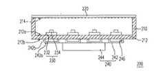
図2は、本発明の一実施例に係るバックライトモジュールを示す図である。図3Aは、図2におけるライトボックスと光源ユニットの平面図であり、図3Bは、図3AのA−A′線に沿う断面図であり、図3Cは、図2におけるマスクとライトバックスの底部との接合を示す斜視図である。図2、図3A、図3B及び図3Cを参照する。本実施例のバックライト200は、ライトボックス210、拡散板220、複数の光源ユニット230及び放熱装置240を含む。ライトボックス210は、互いに対向する底部212と光出し面214を有し、拡散板220は、ライトボックス210の光出し面214に配置され、底部212は、互いに対向する第一の表面212aと第二の表面212bを有し、且つ、第一の表面212aは、光出し面214に接近する。光源ユニット230は、底部212に配置され、即ち、光源ユニット230は、底部212の第一の表面212aまたは第二の表面212bに配置されても良い(本実施例に係る光源ユニット230は、底部212の第一の表面212aに配置される)。各光源ユニット230は、基板232と複数の点光源234を含み、基板232は底部212に配置され、点光源234は基板232上に配置され且つ光出し面214に面する。本実施例において、点光源は、例えば、発光ダイオードまたは他の点光源である。また、放熱装置240は、底部212の第二の表面212bに配置される。本実施例における放熱装置240は、放熱ユニットとファン244を含み、そのうち、放熱ユニットは複数のマスク242を含む。各々のマスク242は、一つの光源ユニット230の真下にある第二の表面212b上に配置される。各マスク242と底部212との間は通風路246を形成する。本実施例におけるマスク242の一端は第一の開口246aを有し、他の端は第二の開口246bを有する。各マスク242の第二の開口246bは連通する。ファン244は放熱ユニットに配置される。具体的に言えば、光源ユニット230の真下にある複数のマスク242は、例えば、マスク248に連通され、これにより、各マスク242の第二の開口246bは連通する。マスク242と底部212との間の最大距離は、例えば、1mmないし10mmである。本実施例において、マスク242は、例えば、頂面242aと両側面242bを有し、そのうち、側面242bは頂面242aと底部212との間に接続される。マスク242と底部212との間の最大距離は、頂面242aから底部212までの距離である。 FIG. 2 is a diagram illustrating a backlight module according to an embodiment of the present invention. 3A is a plan view of the light box and the light source unit in FIG. 2, FIG. 3B is a cross-sectional view taken along the line AA ′ of FIG. 3A, and FIG. 3C is a bottom portion of the mask and the light back in FIG. It is a perspective view which shows joining with. Reference is made to FIGS. 2, 3A, 3B and 3C. The
前述したバックライトモジュール200において、マスク242とマスク248は、一体化で形成されても良い。光源ユニット230の基板232の形状は、例えばストリップ状であり、点光源234は基板232の延伸方向に配列される。基板232は、例えば、回路基板であり、その材料は、熱伝導性の良い金属または合金であっても良いが、これに限られない。具体的に言えば、基板232は、メタルコアプリント配線板(Metal Core Printed Circuit Board:MCPCB)であっても良い。また、ライトボックス210の材料は、アルミを含み、または、その他の熱導電性の良い金属或いは合金であっても良いが、これに限られない。 In the
バックライト200が働くときに、点光源234による熱がまず基板232に伝導され、そして基板232を経由しライトボックス210の底部212に伝導され、これにより、ライトボックス212の、基板232の真下にある部分が高温状態になる。本実施例では、放熱装置240を用いることにより、ライトボックス底部212の、基板232の真下にある部分の温度を有効に下げることができる。これにより、ライトボックス底部212により良い放熱効率を持たせ、点光源234を正常の温度に維持させる。以下、本実施例における放熱装置240について詳細に説明する。 When the
本実施例において、ファン244は、例えば、マスク248の開口248aに設けられる。開口248aの配置位置が例えば、バックライト200の熱集中が生じる箇所に対応する領域である。ファン244は例えば、軸流ファンであり、通風路246内の熱い空気を第二の開口246bから外部へ排出させ、且つ、外部の涼しい空気を第一の開口246bから通風路246に吸い込ませることができ、よって、ライトボックス底部212の、基板232の真下にある部分の温度を有効に下げることができる。従って、従来のバックライトモジュール100と比べ、本実施例のバックライトモジュール200がより良好な放熱効率を有するので、点光源234の発光輝度が過熱の原因で低くなることがなく、また、発光波長が変わることもない。 In this embodiment, the
また、光源ユニット230が一定期間働いた後に、各光源ユニット230の中間部分R1の温度が、通常、その両端の部分R2より高くなるので、基板232に設けられる各点光源234間の温度差を大きくさせ、輝度が不均一になる。本発明の好適な一実施例により、このような問題を避けることができる。図4を参照する。図4は、図3Bにおける一部のマスクと底部との間の距離を調整した後の断面図である。本実施例において、光源ユニット230の中間部分R1に対応するマスク242と底部212との間の最大距離H1が、光源ユニット230の両端部分R2に対応するマスク242と底部212との間の最大距離H2より小さいので、気流が中間部分R1に対応する通風路246を通過するときに高い流速を有し、より多くの熱を排出することができる。具体的に言えば、通風路246内の気流の質量の速度(Mass Velocity)が一定値であり、且つ質量の速度=密度×流速×断面積であるので、気体が通風路246の断面積の小さい部分を通過するときに、その流速が高くなる。本実施例において、H1がH2より小さいので、通風路246の、中間部分R1に対応する断面積が、通風路246の、両端部分R2に対応する断面積より小さい。そのため、気流が中間部分R1に対応する通風路246を通過するときに高い流速を有し、即ち、同じ時間内においてより多くの熱が排出されることができるので、光源ユニット230の中間部分R1の放熱効率を向上することができる。また、本実施例では、マスク242に複数の穴(図示せず)を設けることにより、通風路246の気体進入の分布を調整することができる。 Further, after the
本発明の他の実施例では、各光源ユニット230の真下のライトボックス底部212に放熱穴216(図3Bにおけるライトボックスに放熱穴を設置した後の断面図5Aを参照する)を設けても良い。各々の放熱穴216が対応する基板232を露出させ、通風路内の気流により基板232に対して直接放熱することができるので、光源ユニット230の放熱効率を向上する。他の好適な実施例では、光源ユニット230が放熱穴216の他方側(図5Aにおける光源ユニット230に放熱穴216を設けた後の他方側の断面図5Bを参照する)に設置されても良く、即ち、光源ユニット230が底部212の第二の表面212bに配置される。 In another embodiment of the present invention, a heat radiating hole 216 (refer to FIG. 5A after the heat radiating hole is installed in the light box in FIG. 3B) may be provided in the
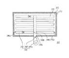
図6は、本発明の好適な実施例における他のバックライトモジュールの底面図である。図6を参照する。本実施例のバックライトモジュール300は、前述したバックライトモジュール200と類似するが、その主な相違点は放熱装置にある。より詳しく言えば、本実施例におけるバックライトモジュール300の放熱装置240′の各マスク242が、マスク248′に接続されることにより、各マスク242の第二の開口246bを連通させる。また、ファン244aは、ブロワーであり、マスク248の開口248aに配置される。ファン244aによる気流が第二の開口246bより通風路に進入し、光源ユニット230に対して冷却を行い、そして、第一の開口246aを経由し通風路から流れ出す。また、本実施例では、バックライトモジュール300にもう一つのファン244b(図6におけるバックライトモジュールにブロワーを増設した後の様子を示す図7を参照する)を増設しても良い。よって、ブロワー244aと244bが同時により多くの気流量を生成し、光源ユニット230の温度を有効に下げることができる。 FIG. 6 is a bottom view of another backlight module according to a preferred embodiment of the present invention. Please refer to FIG. The
図8は、図6におけるバックライトモジュールの通風路を変更した後の様子を示す図である。図8を参照する。本実施例では、ファン244aによる気流の質量の速度が一定値であり、即ち、ファン244aによる気流の質量の速度が各通風路に流れ込んだ風量の総和である。これにより、開口248aに遠い光源ユニット230の熱を排出するための十分な風量を得るために、本実施例は、一部のマスク242の幅を調整することにより、マスク242と底部212との間に形成される通風路の断面積を調整する。具体的に言えば、本実施例は、開口248aに近いマスク242の幅を、開口248aに遠いマスク242の幅より小さくなるように調整する。言い換えると、開口248aに一番近いマスク242の幅W1が最小であり、開口248bに一番遠いマスク242の幅W2が最大であるので、より多くの風量を、開口248aに遠い通風路の部分に流れ込ませ、放熱装置240′による各光源ユニット230の放熱効率が均一になる。 FIG. 8 is a diagram illustrating a state after the ventilation path of the backlight module in FIG. 6 is changed. Please refer to FIG. In this embodiment, the speed of the mass of the airflow by the fan 244a is a constant value, that is, the speed of the mass of the airflow by the fan 244a is the sum of the airflows flowing into the ventilation paths. Thereby, in order to obtain a sufficient air volume for discharging the heat of the
ゆえに、本発明は、ライトボックス底部の第二の表面に放熱装置が設けられ、この放熱装置が複数のマスクと該マスクの近傍に配置される少なくとも一つのファンとを有し、これらのマスクがそれぞれ複数の光源ユニットのうち一つの真下にある第二の表面に設けられる。そのうち、マスクと底部との間は通風路を形成し、ファンによる気流はこの通風路に沿って流れ、光源ユニットを有効に冷却することができる。また、本発明は、各マスクの幅を調整することにより、放熱装置による各光源ユニットの放熱効率を均一にさせることができる。また、ライトボックス底部に複数の放熱穴を適切に増設し、気流に基板に対して直接冷却させることにより、光源ユニットの温度を下げることができる。従来のバックライトモジュールと比べ、本発明のバックライトモジュールは良好な放熱効率を有するので、点光源の発光輝度が過熱の原因で低くなることがなく、また、発光波長が変わることもないと同時に、マスクの調整により温度を均一化する目的を達成することができる。よって、本発明のバックライトモジュールは、輝度が均一でカラーが安定な平面光源を提供することができる。 Therefore, the present invention provides a heat dissipating device on the second surface of the bottom of the light box, the heat dissipating device having a plurality of masks and at least one fan disposed in the vicinity of the masks. Each of the plurality of light source units is provided on a second surface directly below one of the plurality of light source units. Among them, a ventilation path is formed between the mask and the bottom, and the airflow generated by the fan flows along this ventilation path, so that the light source unit can be effectively cooled. Moreover, this invention can make the thermal radiation efficiency of each light source unit by a thermal radiation apparatus uniform by adjusting the width | variety of each mask. Moreover, the temperature of the light source unit can be lowered by appropriately adding a plurality of heat radiation holes at the bottom of the light box and allowing the airflow to cool the substrate directly. Compared with the conventional backlight module, the backlight module of the present invention has a good heat dissipation efficiency, so the emission luminance of the point light source does not decrease due to overheating, and the emission wavelength does not change at the same time The purpose of making the temperature uniform by adjusting the mask can be achieved. Therefore, the backlight module of the present invention can provide a flat light source with uniform brightness and stable color.
以上、本発明の好ましい実施形態を説明したが、本発明はこの実施形態に限定されず、本発明の趣旨を離脱しない限り、本発明に対するあらゆる変更は本発明の範囲に属する。 The preferred embodiment of the present invention has been described above, but the present invention is not limited to this embodiment, and all modifications to the present invention are within the scope of the present invention unless departing from the spirit of the present invention.
100 バックライトモジュール
110 ライトボックス
112 底部
120 光源ユニット
122 基板
124 発光ダイオード
130 ファン
200、300 バックライトモジュール
210 ライトボックス
212 底部
212a 第一の表面
212b 第二の表面
214 光出し面
216 放熱穴
220 拡散板
230 光源ユニット
232 基板
234 点光源
240、240′ 放熱装置
242、248、248′ マスク
242a 頂面
242b 側面
244、244a、244b ファン
246 通風路
246a 第一の開口
246b 第二の開口
248a 穴
R1、R2 領域
H1、H2 マスクと底部との間の距離
W1、W2 通風路の幅100
Claims (9)
Translated fromJapanese前記底部に設けられる複数の光源ユニットであって、当該各光源ユニットが前記底部に配置される基板と当該基板に設けられる複数の点光源とを含む複数の光源ユニットと、
放熱ユニットと少なくとも一つのファンを含む放熱装置であって、当該放熱ユニットは複数のマスクを含み、当該各マスクが前記複数の光源ユニットのうち一つの下方にある前記第二の表面に配置され、当該各マスクと前記底部との間に通風路が形成され、当該各マスクの一端が第一の開口を有し、当該各マスクの他端が第二の開口を有し、当該ファンは当該放熱ユニットに設けられ、当該通風路内の気体を当該第二の開口から流れ出せ、または、気体を当該第二の開口から当該通風路に流れ込ませる放熱装置と、
を有する、
バックライトモジュール。A light box having an opposing bottom and a light exit surface, wherein the bottom has a first surface and a second surface facing each other, and the first surface approaches the light exit surface;
A plurality of light source units provided on the bottom, each light source unit including a substrate disposed on the bottom and a plurality of point light sources provided on the substrate;
A heat dissipating device including a heat dissipating unit and at least one fan, the heat dissipating unit including a plurality of masks, each mask is disposed on the second surface below one of the plurality of light source units, A ventilation path is formed between each mask and the bottom, one end of each mask has a first opening, the other end of each mask has a second opening, and the fan A heat dissipating device that is provided in the unit, allows the gas in the ventilation path to flow out of the second opening, or allows the gas to flow into the ventilation path from the second opening;
Having
Backlight module.
請求項1に記載のバックライトモジュール。The bottom portion has a plurality of heat radiation holes, and each heat radiation hole exposes the corresponding substrate.
The backlight module according to claim 1.
請求項1に記載のバックライトモジュール。The maximum distance between each mask and the bottom is from 1 mm to 10 mm;
The backlight module according to claim 1.
請求項1に記載のバックライトモジュール。The fan is an axial fan or a blower.
The backlight module according to claim 1.
請求項1に記載のバックライトモジュール。The point light source is a light emitting diode;
The backlight module according to claim 1.
請求項1に記載のバックライトモジュール。The mask is provided with a plurality of holes,
The backlight module according to claim 1.
請求項1に記載のバックライトモジュール。The maximum distance between the portion corresponding to the intermediate portion of the light source unit and the bottom of each mask is greater than the maximum distance between the portion corresponding to both end portions of the light source unit and the bottom of the mask. small,
The backlight module according to claim 1.
請求項1に記載のバックライトモジュール。A diffusion plate disposed on the light exit surface of the light box;
The backlight module according to claim 1.
請求項1に記載のバックライトモジュール。Each of the masks is disposed on the second surface immediately below one of the plurality of light source units.
The backlight module according to claim 1.
Applications Claiming Priority (1)
| Application Number | Priority Date | Filing Date | Title |
|---|---|---|---|
| TW095139970ATWI345661B (en) | 2006-10-30 | 2006-10-30 | Backlight module |
Publications (1)
| Publication Number | Publication Date |
|---|---|
| JP2008112719Atrue JP2008112719A (en) | 2008-05-15 |
Family
ID=39329866
Family Applications (1)
| Application Number | Title | Priority Date | Filing Date |
|---|---|---|---|
| JP2007226251APendingJP2008112719A (en) | 2006-10-30 | 2007-08-31 | Backlight module |
Country Status (3)
| Country | Link |
|---|---|
| US (1) | US7682047B2 (en) |
| JP (1) | JP2008112719A (en) |
| TW (1) | TWI345661B (en) |
Cited By (12)
| Publication number | Priority date | Publication date | Assignee | Title |
|---|---|---|---|---|
| JP2011064991A (en)* | 2009-09-18 | 2011-03-31 | Hitachi Displays Ltd | Liquid crystal display device |
| WO2011072217A3 (en)* | 2009-12-10 | 2011-10-27 | Manufacturing Resources International, Inc. | Modular distributed components for led backlight |
| WO2011135885A1 (en)* | 2010-04-28 | 2011-11-03 | シャープ株式会社 | Led backlight and liquid crystal display device |
| WO2012102163A1 (en)* | 2011-01-26 | 2012-08-02 | シャープ株式会社 | Lighting device, display device, and television receiver |
| US10126579B2 (en) | 2013-03-14 | 2018-11-13 | Manfuacturing Resources International, Inc. | Rigid LCD assembly |
| US10191212B2 (en) | 2013-12-02 | 2019-01-29 | Manufacturing Resources International, Inc. | Expandable light guide for backlight |
| US10261362B2 (en) | 2015-09-01 | 2019-04-16 | Manufacturing Resources International, Inc. | Optical sheet tensioner |
| US10431166B2 (en) | 2009-06-03 | 2019-10-01 | Manufacturing Resources International, Inc. | Dynamic dimming LED backlight |
| US10466539B2 (en) | 2013-07-03 | 2019-11-05 | Manufacturing Resources International, Inc. | Airguide backlight assembly |
| US10527276B2 (en) | 2014-04-17 | 2020-01-07 | Manufacturing Resources International, Inc. | Rod as a lens element for light emitting diodes |
| US10649273B2 (en) | 2014-10-08 | 2020-05-12 | Manufacturing Resources International, Inc. | LED assembly for transparent liquid crystal display and static graphic |
| US12429726B1 (en) | 2023-10-02 | 2025-09-30 | Manufacturing Resources International, Inc. | Optical stack with a liquid crystal layer and a micro lens array, electronic display assembly, and related methods |
Families Citing this family (47)
| Publication number | Priority date | Publication date | Assignee | Title |
|---|---|---|---|---|
| US12185512B2 (en) | 2007-11-16 | 2024-12-31 | Manufacturing Resources International, Inc. | Electronic display assembly with thermal management |
| US8497972B2 (en) | 2009-11-13 | 2013-07-30 | Manufacturing Resources International, Inc. | Thermal plate with optional cooling loop in electronic display |
| US8654302B2 (en) | 2008-03-03 | 2014-02-18 | Manufacturing Resources International, Inc. | Heat exchanger for an electronic display |
| US8693185B2 (en) | 2008-03-26 | 2014-04-08 | Manufacturing Resources International, Inc. | System and method for maintaining a consistent temperature gradient across an electronic display |
| TWI394918B (en) | 2008-11-28 | 2013-05-01 | Young Green Energy Co | Lighting module and lighting system |
| US10827656B2 (en) | 2008-12-18 | 2020-11-03 | Manufacturing Resources International, Inc. | System for cooling an electronic image assembly with circulating gas and ambient gas |
| US8749749B2 (en) | 2008-12-18 | 2014-06-10 | Manufacturing Resources International, Inc. | System for cooling an electronic image assembly with manifolds and ambient gas |
| CN101994924A (en)* | 2009-08-12 | 2011-03-30 | 扬光绿能股份有限公司 | Lighting system |
| TWI381131B (en)* | 2009-08-27 | 2013-01-01 | Sunonwealth Electr Mach Ind Co | Heat dissipating apparatus for lighting module |
| US20120320566A1 (en)* | 2010-02-25 | 2012-12-20 | Sharp Kabushiki Kaisha | Liquid crystal display device, and led backlight unit |
| US20110292656A1 (en)* | 2010-05-26 | 2011-12-01 | Hella Kg Hueck And Co. | Luminaire cooling apparatus |
| US20120275152A1 (en)* | 2011-04-29 | 2012-11-01 | Phoseon Technology, Inc. | Heat sink for light modules |
| CN103206689B (en)* | 2012-01-11 | 2017-09-12 | 欧司朗股份有限公司 | Heat abstractor, light-emitting device and the light fixture with the light-emitting device |
| WO2014149773A1 (en) | 2013-03-15 | 2014-09-25 | Manufacturing Resources International, Inc. | Heat exchange assembly for an electronic display |
| AU2014287438B2 (en) | 2013-07-08 | 2017-09-28 | Manufacturing Resources International, Inc. | Figure eight closed loop cooling system for electronic display |
| CN104061535A (en)* | 2013-12-11 | 2014-09-24 | 浙江金仕朗光电科技有限公司 | LED lamp |
| JP6305564B2 (en) | 2014-04-30 | 2018-04-04 | マニュファクチャリング・リソーシズ・インターナショナル・インコーポレーテッド | Back-to-back electronic display assembly |
| CN104534359B (en)* | 2014-12-25 | 2017-10-03 | 武汉天马微电子有限公司 | Backlight device |
| US9723765B2 (en) | 2015-02-17 | 2017-08-01 | Manufacturing Resources International, Inc. | Perimeter ventilation system for electronic display |
| US10820445B2 (en) | 2016-03-04 | 2020-10-27 | Manufacturing Resources International, Inc. | Cooling system for double sided display assembly |
| US10480767B2 (en)* | 2016-05-31 | 2019-11-19 | Air Motion Systems, Inc. | Air cooled array and system for cooling light emitting diode systems |
| TWI616616B (en) | 2017-03-20 | 2018-03-01 | 蔡高德 | LED plane light source lamp |
| KR102262912B1 (en) | 2017-04-27 | 2021-06-10 | 매뉴팩처링 리소시스 인터내셔널 인코포레이티드 | A system and method for preventing warping of a display device |
| US10485113B2 (en) | 2017-04-27 | 2019-11-19 | Manufacturing Resources International, Inc. | Field serviceable and replaceable display |
| CN107589592B (en)* | 2017-09-08 | 2020-06-23 | 深圳市华星光电技术有限公司 | Heat dissipation structure for backlight module and backlight module |
| US10559965B2 (en) | 2017-09-21 | 2020-02-11 | Manufacturing Resources International, Inc. | Display assembly having multiple charging ports |
| US10602626B2 (en) | 2018-07-30 | 2020-03-24 | Manufacturing Resources International, Inc. | Housing assembly for an integrated display unit |
| CN117826478A (en)* | 2018-08-22 | 2024-04-05 | 索尼公司 | Display device |
| US11730090B2 (en)* | 2019-02-25 | 2023-08-22 | Freight Farms, Inc. | Closed farm system with air flow control |
| US11096317B2 (en) | 2019-02-26 | 2021-08-17 | Manufacturing Resources International, Inc. | Display assembly with loopback cooling |
| US10795413B1 (en) | 2019-04-03 | 2020-10-06 | Manufacturing Resources International, Inc. | Electronic display assembly with a channel for ambient air in an access panel |
| JP7458853B2 (en)* | 2020-03-30 | 2024-04-01 | キヤノン株式会社 | Light source device, illumination device, and exposure device. |
| US11477923B2 (en) | 2020-10-02 | 2022-10-18 | Manufacturing Resources International, Inc. | Field customizable airflow system for a communications box |
| US11470749B2 (en) | 2020-10-23 | 2022-10-11 | Manufacturing Resources International, Inc. | Forced air cooling for display assemblies using centrifugal fans |
| US11778757B2 (en) | 2020-10-23 | 2023-10-03 | Manufacturing Resources International, Inc. | Display assemblies incorporating electric vehicle charging equipment |
| US12408312B2 (en) | 2021-07-28 | 2025-09-02 | Manufacturing Resources International, Inc. | Display assemblies with vents |
| US11966263B2 (en) | 2021-07-28 | 2024-04-23 | Manufacturing Resources International, Inc. | Display assemblies for providing compressive forces at electronic display layers |
| US11919393B2 (en) | 2021-08-23 | 2024-03-05 | Manufacturing Resources International, Inc. | Display assemblies inducing relatively turbulent flow and integrating electric vehicle charging equipment |
| US11744054B2 (en) | 2021-08-23 | 2023-08-29 | Manufacturing Resources International, Inc. | Fan unit for providing improved airflow within display assemblies |
| US11762231B2 (en) | 2021-08-23 | 2023-09-19 | Manufacturing Resources International, Inc. | Display assemblies inducing turbulent flow |
| US11968813B2 (en) | 2021-11-23 | 2024-04-23 | Manufacturing Resources International, Inc. | Display assembly with divided interior space |
| US12072561B2 (en) | 2022-07-22 | 2024-08-27 | Manufacturing Resources International, Inc. | Self-contained electronic display assembly, mounting structure and methods for the same |
| US12010813B2 (en) | 2022-07-22 | 2024-06-11 | Manufacturing Resources International, Inc. | Self-contained electronic display assembly, mounting structure and methods for the same |
| US12035486B1 (en) | 2022-07-25 | 2024-07-09 | Manufacturing Resources International, Inc. | Electronic display assembly with fabric panel communications box |
| CN114967239B (en)* | 2022-07-29 | 2022-11-25 | 惠科股份有限公司 | Back plate of backlight module, backlight module and display device |
| CN115113439B (en)* | 2022-08-23 | 2022-12-23 | 惠科股份有限公司 | Backlight module and display device |
| CN115574303B (en)* | 2022-09-26 | 2023-06-16 | 深圳市瀚达美电子有限公司 | Large-size LED backlight source with high heat dissipation |
Citations (7)
| Publication number | Priority date | Publication date | Assignee | Title |
|---|---|---|---|---|
| JP2003092009A (en)* | 2001-09-17 | 2003-03-28 | Matsushita Electric Ind Co Ltd | Lighting equipment |
| JP2005121897A (en)* | 2003-10-16 | 2005-05-12 | Nec Lcd Technologies Ltd | Liquid crystal display |
| JP2005229095A (en)* | 2004-01-13 | 2005-08-25 | Seiko Epson Corp | Light source device and projection display device |
| JP2005316337A (en)* | 2004-04-30 | 2005-11-10 | Sony Corp | Backlight device |
| JP2006114501A (en)* | 2004-10-15 | 2006-04-27 | Lg Electronics Inc | Light-emitting element package and backlight unit for liquid crystal display using the same |
| JP2006172934A (en)* | 2004-12-16 | 2006-06-29 | Imac Co Ltd | Substrate structure for lighting device, and its manufacturing device, and lighting device |
| JP2006178451A (en)* | 2004-12-20 | 2006-07-06 | Samsung Electronics Co Ltd | Backlight system and liquid crystal display device employing the same |
Family Cites Families (10)
| Publication number | Priority date | Publication date | Assignee | Title |
|---|---|---|---|---|
| JPH10106342A (en)* | 1996-09-30 | 1998-04-24 | Sony Corp | Space light source device |
| JP2006106272A (en)* | 2004-10-04 | 2006-04-20 | Sony Corp | Display apparatus |
| WO2006038778A1 (en)* | 2004-10-05 | 2006-04-13 | Samsung Electronics Co., Ltd. | Backlight unit |
| KR20060070176A (en) | 2004-12-20 | 2006-06-23 | 삼성전자주식회사 | Cooling device and liquid crystal display including the same |
| TWI334048B (en)* | 2004-12-31 | 2010-12-01 | Au Optronics Corp | Backlight module |
| CN100517008C (en)* | 2005-05-17 | 2009-07-22 | 鸿富锦精密工业(深圳)有限公司 | Direct type backlight module |
| CN100437275C (en)* | 2005-05-18 | 2008-11-26 | 鸿富锦精密工业(深圳)有限公司 | Direct type backlight module assembly |
| TWI307799B (en)* | 2005-05-25 | 2009-03-21 | Coretronic Corp | Backlight module |
| CN100437277C (en)* | 2005-09-22 | 2008-11-26 | 鸿富锦精密工业(深圳)有限公司 | Backlight module |
| JP4830436B2 (en)* | 2005-10-03 | 2011-12-07 | 株式会社日立製作所 | Display device |
- 2006
- 2006-10-30TWTW095139970Apatent/TWI345661B/ennot_activeIP Right Cessation
- 2007
- 2007-08-31JPJP2007226251Apatent/JP2008112719A/enactivePending
- 2007-09-07USUS11/851,391patent/US7682047B2/ennot_activeExpired - Fee Related
Patent Citations (7)
| Publication number | Priority date | Publication date | Assignee | Title |
|---|---|---|---|---|
| JP2003092009A (en)* | 2001-09-17 | 2003-03-28 | Matsushita Electric Ind Co Ltd | Lighting equipment |
| JP2005121897A (en)* | 2003-10-16 | 2005-05-12 | Nec Lcd Technologies Ltd | Liquid crystal display |
| JP2005229095A (en)* | 2004-01-13 | 2005-08-25 | Seiko Epson Corp | Light source device and projection display device |
| JP2005316337A (en)* | 2004-04-30 | 2005-11-10 | Sony Corp | Backlight device |
| JP2006114501A (en)* | 2004-10-15 | 2006-04-27 | Lg Electronics Inc | Light-emitting element package and backlight unit for liquid crystal display using the same |
| JP2006172934A (en)* | 2004-12-16 | 2006-06-29 | Imac Co Ltd | Substrate structure for lighting device, and its manufacturing device, and lighting device |
| JP2006178451A (en)* | 2004-12-20 | 2006-07-06 | Samsung Electronics Co Ltd | Backlight system and liquid crystal display device employing the same |
Cited By (20)
| Publication number | Priority date | Publication date | Assignee | Title |
|---|---|---|---|---|
| US8760613B2 (en) | 2008-12-18 | 2014-06-24 | Manufacturing Resources International, Inc. | Modular distributed components for LED backlight |
| US10431166B2 (en) | 2009-06-03 | 2019-10-01 | Manufacturing Resources International, Inc. | Dynamic dimming LED backlight |
| JP2011064991A (en)* | 2009-09-18 | 2011-03-31 | Hitachi Displays Ltd | Liquid crystal display device |
| WO2011072217A3 (en)* | 2009-12-10 | 2011-10-27 | Manufacturing Resources International, Inc. | Modular distributed components for led backlight |
| WO2011135885A1 (en)* | 2010-04-28 | 2011-11-03 | シャープ株式会社 | Led backlight and liquid crystal display device |
| WO2012102163A1 (en)* | 2011-01-26 | 2012-08-02 | シャープ株式会社 | Lighting device, display device, and television receiver |
| US10831050B2 (en) | 2013-03-14 | 2020-11-10 | Manufacturing Resources International, Inc. | Rigid LCD assembly |
| US10126579B2 (en) | 2013-03-14 | 2018-11-13 | Manfuacturing Resources International, Inc. | Rigid LCD assembly |
| US10466539B2 (en) | 2013-07-03 | 2019-11-05 | Manufacturing Resources International, Inc. | Airguide backlight assembly |
| US10191212B2 (en) | 2013-12-02 | 2019-01-29 | Manufacturing Resources International, Inc. | Expandable light guide for backlight |
| US10921510B2 (en) | 2013-12-02 | 2021-02-16 | Manufacturing Resources International, Inc. | Expandable light guide for backlight |
| US10527276B2 (en) | 2014-04-17 | 2020-01-07 | Manufacturing Resources International, Inc. | Rod as a lens element for light emitting diodes |
| US10649273B2 (en) | 2014-10-08 | 2020-05-12 | Manufacturing Resources International, Inc. | LED assembly for transparent liquid crystal display and static graphic |
| US11474393B2 (en) | 2014-10-08 | 2022-10-18 | Manufacturing Resources International, Inc. | Lighting assembly for electronic display and graphic |
| US12032240B2 (en) | 2014-10-08 | 2024-07-09 | Manufacturing Resources International, Inc. | Display system for refrigerated display case |
| US10768483B2 (en) | 2015-09-01 | 2020-09-08 | Manufacturing Resources International, Inc. | Optical sheet tensioning device |
| US10261362B2 (en) | 2015-09-01 | 2019-04-16 | Manufacturing Resources International, Inc. | Optical sheet tensioner |
| US11275269B2 (en) | 2015-09-01 | 2022-03-15 | Manufacturing Resources International, Inc. | Optical sheet tensioning device |
| US11656498B2 (en) | 2015-09-01 | 2023-05-23 | Manufacturing Resources International, Inc. | Optical sheet tensioning device |
| US12429726B1 (en) | 2023-10-02 | 2025-09-30 | Manufacturing Resources International, Inc. | Optical stack with a liquid crystal layer and a micro lens array, electronic display assembly, and related methods |
Also Published As
| Publication number | Publication date |
|---|---|
| US20080101065A1 (en) | 2008-05-01 |
| TWI345661B (en) | 2011-07-21 |
| TW200819866A (en) | 2008-05-01 |
| US7682047B2 (en) | 2010-03-23 |
Similar Documents
| Publication | Publication Date | Title |
|---|---|---|
| JP2008112719A (en) | Backlight module | |
| JP5295683B2 (en) | Power LED lighting device | |
| US7259964B2 (en) | Display device | |
| US20210033916A1 (en) | Display apparatus | |
| JP5555084B2 (en) | Light source device | |
| CN110389474A (en) | Liquid crystal display device | |
| TWI627072B (en) | Light irradiation device | |
| JP2006114501A (en) | Light-emitting element package and backlight unit for liquid crystal display using the same | |
| TW201606228A (en) | Light irradiation device | |
| US20080019125A1 (en) | Backlight module | |
| JP3190306U (en) | Light module heatsink | |
| JP2009104858A (en) | Liquid crystal display device | |
| JP2008041638A (en) | Heat dissipation device for backlight light source for flat panel display | |
| JP6101518B2 (en) | Display device | |
| TWI598534B (en) | Light irradiation device | |
| TW201135124A (en) | Light source unit using light-emitting element | |
| CN101221302B (en) | Backlight module | |
| JP2014067767A (en) | Heat sink and lighting unit equipped with the same | |
| JP2008043047A (en) | Cooling structure for power converter | |
| JP2016062677A (en) | Light irradiation device | |
| JP2013206693A (en) | Led lighting device | |
| JP2013229396A (en) | Heat sink and luminaire including the same | |
| JP2013165155A (en) | Heat sink and lighting device including the same | |
| JP2007139981A (en) | Display-integrated electronic device | |
| JP2022157844A (en) | Light irradiation device |
Legal Events
| Date | Code | Title | Description |
|---|---|---|---|
| A977 | Report on retrieval | Free format text:JAPANESE INTERMEDIATE CODE: A971007 Effective date:20100423 | |
| A131 | Notification of reasons for refusal | Free format text:JAPANESE INTERMEDIATE CODE: A131 Effective date:20100518 | |
| A521 | Written amendment | Free format text:JAPANESE INTERMEDIATE CODE: A523 Effective date:20100817 | |
| A02 | Decision of refusal | Free format text:JAPANESE INTERMEDIATE CODE: A02 Effective date:20111101 |