JP2008110266A - Guide wire - Google Patents
Guide wireDownload PDFInfo
- Publication number
- JP2008110266A JP2008110266AJP2008025771AJP2008025771AJP2008110266AJP 2008110266 AJP2008110266 AJP 2008110266AJP 2008025771 AJP2008025771 AJP 2008025771AJP 2008025771 AJP2008025771 AJP 2008025771AJP 2008110266 AJP2008110266 AJP 2008110266A
- Authority
- JP
- Japan
- Prior art keywords
- wire
- guide wire
- inner layer
- distal end
- constant
- Prior art date
- Legal status (The legal status is an assumption and is not a legal conclusion. Google has not performed a legal analysis and makes no representation as to the accuracy of the status listed.)
- Pending
Links
- 239000000463materialSubstances0.000claimsdescription74
- 230000007423decreaseEffects0.000claimsdescription19
- 239000007769metal materialSubstances0.000claimsdescription16
- 229910052751metalInorganic materials0.000claimsdescription6
- 239000002184metalSubstances0.000claimsdescription6
- 239000010410layerSubstances0.000description113
- 229910045601alloyInorganic materials0.000description30
- 239000000956alloySubstances0.000description30
- 238000005452bendingMethods0.000description30
- 239000011162core materialSubstances0.000description30
- 238000000034methodMethods0.000description24
- 210000004204blood vesselAnatomy0.000description22
- 230000003247decreasing effectEffects0.000description19
- 210000004351coronary vesselAnatomy0.000description16
- 238000003466weldingMethods0.000description16
- 239000000470constituentSubstances0.000description12
- 239000010935stainless steelSubstances0.000description11
- 229910001220stainless steelInorganic materials0.000description11
- 229910000531Co alloyInorganic materials0.000description10
- 230000005540biological transmissionEffects0.000description10
- KHYBPSFKEHXSLX-UHFFFAOYSA-NiminotitaniumChemical compound[Ti]=NKHYBPSFKEHXSLX-UHFFFAOYSA-N0.000description8
- 229910001000nickel titaniumInorganic materials0.000description8
- 230000002093peripheral effectEffects0.000description8
- 238000005498polishingMethods0.000description8
- 210000002376aorta thoracicAnatomy0.000description6
- 239000011248coating agentSubstances0.000description6
- 238000000576coating methodMethods0.000description6
- 230000009467reductionEffects0.000description6
- 206010057469Vascular stenosisDiseases0.000description5
- 238000010586diagramMethods0.000description4
- 238000007747platingMethods0.000description4
- 239000000126substanceSubstances0.000description4
- 238000005219brazingMethods0.000description3
- 230000000694effectsEffects0.000description3
- 238000000227grindingMethods0.000description3
- 238000010438heat treatmentMethods0.000description3
- -1polyethylenePolymers0.000description3
- 239000002861polymer materialSubstances0.000description3
- 229910000679solderInorganic materials0.000description3
- 230000037303wrinklesEffects0.000description3
- 239000000853adhesiveSubstances0.000description2
- 230000001070adhesive effectEffects0.000description2
- 230000008859changeEffects0.000description2
- HVYWMOMLDIMFJA-DPAQBDIFSA-NcholesterolChemical compoundC1C=C2C[C@@H](O)CC[C@]2(C)[C@@H]2[C@@H]1[C@@H]1CC[C@H]([C@H](C)CCCC(C)C)[C@@]1(C)CC2HVYWMOMLDIMFJA-DPAQBDIFSA-N0.000description2
- 229920001577copolymerPolymers0.000description2
- 230000002209hydrophobic effectEffects0.000description2
- 238000005304joiningMethods0.000description2
- FPYJFEHAWHCUMM-UHFFFAOYSA-Nmaleic anhydrideChemical compoundO=C1OC(=O)C=C1FPYJFEHAWHCUMM-UHFFFAOYSA-N0.000description2
- 238000004021metal weldingMethods0.000description2
- 239000000203mixtureSubstances0.000description2
- 229910000510noble metalInorganic materials0.000description2
- 230000000704physical effectEffects0.000description2
- BASFCYQUMIYNBI-UHFFFAOYSA-NplatinumChemical compound[Pt]BASFCYQUMIYNBI-UHFFFAOYSA-N0.000description2
- 229920002401polyacrylamidePolymers0.000description2
- 229920001343polytetrafluoroethylenePolymers0.000description2
- 239000004810polytetrafluoroethyleneSubstances0.000description2
- 238000012545processingMethods0.000description2
- 238000007493shaping processMethods0.000description2
- 238000001356surgical procedureMethods0.000description2
- 230000007704transitionEffects0.000description2
- 238000007740vapor depositionMethods0.000description2
- 238000005491wire drawingMethods0.000description2
- PKAUISBSZACZJI-UHFFFAOYSA-NCC(=CC(=O)N)C.C(C(=C)C)(=O)OChemical compoundCC(=CC(=O)N)C.C(C(=C)C)(=O)OPKAUISBSZACZJI-UHFFFAOYSA-N0.000description1
- 229910017518Cu ZnInorganic materials0.000description1
- 229910017752Cu-ZnInorganic materials0.000description1
- 229910017943Cu—ZnInorganic materials0.000description1
- YCKRFDGAMUMZLT-UHFFFAOYSA-NFluorine atomChemical compound[F]YCKRFDGAMUMZLT-UHFFFAOYSA-N0.000description1
- 229910003310Ni-AlInorganic materials0.000description1
- 239000004677NylonSubstances0.000description1
- 208000031481Pathologic ConstrictionDiseases0.000description1
- 229920003171Poly (ethylene oxide)Polymers0.000description1
- 239000004952PolyamideSubstances0.000description1
- 239000004698PolyethyleneSubstances0.000description1
- 239000004743PolypropyleneSubstances0.000description1
- 239000004793PolystyreneSubstances0.000description1
- 239000004372Polyvinyl alcoholSubstances0.000description1
- 239000002253acidSubstances0.000description1
- 230000002411adverseEffects0.000description1
- 229910052782aluminiumInorganic materials0.000description1
- 238000002583angiographyMethods0.000description1
- 210000000709aortaAnatomy0.000description1
- 230000008901benefitEffects0.000description1
- 229910052790berylliumInorganic materials0.000description1
- 230000015572biosynthetic processEffects0.000description1
- 229920001400block copolymerPolymers0.000description1
- 230000017531blood circulationEffects0.000description1
- 229920003174cellulose-based polymerPolymers0.000description1
- 238000012993chemical processingMethods0.000description1
- 235000012000cholesterolNutrition0.000description1
- 239000011247coating layerSubstances0.000description1
- 239000002131composite materialSubstances0.000description1
- TVZPLCNGKSPOJA-UHFFFAOYSA-Ncopper zincChemical compound[Cu].[Zn]TVZPLCNGKSPOJA-UHFFFAOYSA-N0.000description1
- 238000007887coronary angioplastyMethods0.000description1
- 230000008878couplingEffects0.000description1
- 238000010168coupling processMethods0.000description1
- 238000005859coupling reactionMethods0.000description1
- 230000007547defectEffects0.000description1
- 229920001971elastomerPolymers0.000description1
- 239000000806elastomerSubstances0.000description1
- 238000005530etchingMethods0.000description1
- 229920000840ethylene tetrafluoroethylene copolymerPolymers0.000description1
- 230000001747exhibiting effectEffects0.000description1
- 210000001105femoral arteryAnatomy0.000description1
- 239000012530fluidSubstances0.000description1
- 239000011737fluorineSubstances0.000description1
- 229910052731fluorineInorganic materials0.000description1
- 238000002594fluoroscopyMethods0.000description1
- 229910052733galliumInorganic materials0.000description1
- PCHJSUWPFVWCPO-UHFFFAOYSA-NgoldChemical compound[Au]PCHJSUWPFVWCPO-UHFFFAOYSA-N0.000description1
- 229910052737goldInorganic materials0.000description1
- 239000010931goldSubstances0.000description1
- 238000001727in vivoMethods0.000description1
- 238000003780insertionMethods0.000description1
- 230000037431insertionEffects0.000description1
- 238000007733ion platingMethods0.000description1
- 238000004519manufacturing processMethods0.000description1
- 229910052759nickelInorganic materials0.000description1
- 229920001778nylonPolymers0.000description1
- 229920003023plasticPolymers0.000description1
- 239000004033plasticSubstances0.000description1
- 229910052697platinumInorganic materials0.000description1
- 229920002647polyamidePolymers0.000description1
- 229920000515polycarbonatePolymers0.000description1
- 239000004417polycarbonateSubstances0.000description1
- 229920000728polyesterPolymers0.000description1
- 229920000573polyethylenePolymers0.000description1
- 229920001155polypropylenePolymers0.000description1
- 229920001296polysiloxanePolymers0.000description1
- 229920002223polystyrenePolymers0.000description1
- 229920002635polyurethanePolymers0.000description1
- 239000004814polyurethaneSubstances0.000description1
- 229920002451polyvinyl alcoholPolymers0.000description1
- 239000004800polyvinyl chlorideSubstances0.000description1
- 229920000915polyvinyl chloridePolymers0.000description1
- 229920000036polyvinylpyrrolidonePolymers0.000description1
- 239000001267polyvinylpyrrolidoneSubstances0.000description1
- 235000013855polyvinylpyrrolidoneNutrition0.000description1
- 229920005989resinPolymers0.000description1
- 239000011347resinSubstances0.000description1
- 229910052710siliconInorganic materials0.000description1
- 229920002050silicone resinPolymers0.000description1
- 238000004544sputter depositionMethods0.000description1
- 230000036262stenosisEffects0.000description1
- 208000037804stenosisDiseases0.000description1
- 229920003002synthetic resinPolymers0.000description1
- 239000000057synthetic resinSubstances0.000description1
- 229910052718tinInorganic materials0.000description1
- 230000009466transformationEffects0.000description1
- WFKWXMTUELFFGS-UHFFFAOYSA-NtungstenChemical compound[W]WFKWXMTUELFFGS-UHFFFAOYSA-N0.000description1
- 239000010937tungstenSubstances0.000description1
- 229910052721tungstenInorganic materials0.000description1
- 230000002792vascularEffects0.000description1
- 238000004804windingMethods0.000description1
- 229910052725zincInorganic materials0.000description1
Images


Landscapes
- Media Introduction/Drainage Providing Device (AREA)
Abstract
Description
Translated fromJapanese本発明は、ガイドワイヤ、特に血管のような体腔内にカテーテルを導入する際に用いられるガイドワイヤに関する。 The present invention relates to a guide wire, and particularly to a guide wire used when a catheter is introduced into a body cavity such as a blood vessel.
ガイドワイヤは、例えばPTCA術(Percutaneous Transluminal Coronary Angioplasty:経皮的冠状動脈血管形成術)のような、外科的手術が困難な部位の治療、または人体への低侵襲を目的とした治療や、心臓血管造影などの検査に用いられるカテーテルを誘導するのに使用される。PTCA術に用いられるガイドワイヤは、ガイドワイヤの先端をバルーンカテーテルの先端より突出させた状態にて、バルーンカテーテルと共に目的部位である血管狭窄部付近まで挿入され、バルーンカテーテルの先端部を血管狭窄部付近まで誘導する。 The guide wire can be used for the treatment of a site where surgical operation is difficult, such as PTCA (Percutaneous Transluminal Coronary Angioplasty), or for the purpose of minimally invasive to the human body, Used to guide catheters used for examinations such as angiography. A guide wire used for PTCA surgery is inserted to the vicinity of the target vascular stenosis portion together with the balloon catheter with the tip of the guide wire protruding from the tip of the balloon catheter. Guide to near.
血管は、複雑に湾曲しており、カテーテルを血管に挿入する際に用いるガイドワイヤには、適度の可撓性、基端部における操作を先端側に伝達するための押し込み性およびトルク伝達性(これらを総称して「操作性」という)、さらには耐キンク性(耐折れ曲がり性)等が要求される。それらの特性の内、適度の柔軟性を得るための構造として、ガイドワイヤの細い先端芯材の回りに曲げに対する柔軟性を有する金属コイルを備えたものや、柔軟性、復元性を付与するためガイドワイヤの芯材にNi−Ti等の超弾性線を用いたものがある。 The blood vessel is intricately curved, and the guide wire used to insert the catheter into the blood vessel has moderate flexibility, pushability and torque transmission for transmitting the operation at the proximal end to the distal side ( These are collectively referred to as “operability”), and further kink resistance (bending resistance) is required. Among these characteristics, as a structure for obtaining moderate flexibility, a structure provided with a metal coil having flexibility for bending around a thin tip core material of a guide wire, and for providing flexibility and restorability There is a guide wire using a super elastic wire such as Ni-Ti as a core material.
従来のガイドワイヤは、芯材が実質的に1種の材料から構成されており、ガイドワイヤの操作性を高めるために、比較的弾性率の高い材料が用いられ、その影響としてガイドワイヤ先端部の柔軟性は失われている。また、ガイドワイヤの先端部の柔軟性を得るために、比較的弾性率の低い材料を用いると、ガイドワイヤの基端側における操作性が失われる。このように、必要とされる柔軟性および操作性を、1種の芯材で満たすことは困難とされていた。 In the conventional guide wire, the core material is substantially composed of one material, and a material having a relatively high elastic modulus is used in order to improve the operability of the guide wire. The flexibility is lost. Further, if a material having a relatively low elastic modulus is used in order to obtain the flexibility of the distal end portion of the guide wire, the operability on the proximal end side of the guide wire is lost. Thus, it has been difficult to satisfy the required flexibility and operability with one kind of core material.
このような欠点を改良するため、例えば芯材にNi−Ti合金線を用い、その先端側と基端側とに異なった条件で熱処理を施し、先端部の柔軟性を高め、基端側の剛性を高めたガイドワイヤが提案されている(例えば、特許文献1参照)。 In order to improve such a defect, for example, a Ni-Ti alloy wire is used as a core material, and heat treatment is performed on the distal end side and the proximal end side under different conditions to increase the flexibility of the distal end portion. A guide wire with increased rigidity has been proposed (see, for example, Patent Document 1).
しかし、このような熱処理による柔軟性の制御には限界があり、先端部では十分な柔軟性が得られても、基端側では必ずしも満足する剛性が得られないことがあった。 However, there is a limit to the control of flexibility by such heat treatment, and even if sufficient flexibility is obtained at the distal end portion, there is a case where satisfactory rigidity is not always obtained at the proximal end side.
本発明の目的は、操作性および耐キンク性に優れたガイドワイヤを提供することにある。 An object of the present invention is to provide a guide wire excellent in operability and kink resistance.
このような目的は、下記(1)〜(6)の本発明により達成される。また、(7)〜(14)であることが好ましい。 Such an object is achieved by the present inventions (1) to (6) below. Moreover, it is preferable that it is (7)-(14).
(1) 先端側に配置されたリシェイプ可能な金属材料で構成された先端側ワイヤと、
前記先端側ワイヤの基端側に配置され、内層と外層とを有する中間ワイヤと、
前記中間ワイヤの基端側に配置され、前記先端側ワイヤを構成する金属材料と同一または同種の材料で構成された線状の基端側ワイヤとを有し、
前記内層は、先端方向に向かってその外径が漸減するテーパ部と、その外径が長手方向に沿ってほぼ一定の径一定部とをそれぞれ複数有し、これらが交互に配置されており、
前記外層は、先端方向に向かってその外径が漸減するテーパ部と、その外径が長手方向に沿ってほぼ一定の径一定部とをそれぞれ複数有し、これらが交互に配置されていることを特徴とするガイドワイヤ。(1) a tip side wire made of a reshapeable metal material disposed on the tip side;
An intermediate wire disposed on the proximal side of the distal wire and having an inner layer and an outer layer;
A linear proximal end wire arranged on the proximal end side of the intermediate wire and made of the same or the same kind of material as the metal material constituting the distal end side wire;
The inner layer has a plurality of tapered portions whose outer diameters gradually decrease toward the distal direction, and plural constant diameter constant portions whose outer diameters are substantially constant along the longitudinal direction, and these are alternately arranged.
The outer layer has a plurality of taper portions whose outer diameters gradually decrease toward the tip direction, and a plurality of constant diameter constant portions whose outer diameters are substantially constant along the longitudinal direction, and these are arranged alternately. A guide wire characterized by
(2) 前記内層のテーパ部と前記外層のテーパ部とは、その一方が他方に包含されているかまたは重なっている上記(1)に記載のガイドワイヤ。 (2) The guide wire according to (1), wherein one of the tapered portion of the inner layer and the tapered portion of the outer layer is included in or overlaps the other.
(3) 前記内層のテーパ部と前記外層の径一定部とは、その一方が他方に包含されているかまたは重なっている上記(1)または(2)に記載のガイドワイヤ。 (3) The guide wire according to (1) or (2), wherein one of the tapered portion of the inner layer and the constant diameter portion of the outer layer is included in or overlaps the other.
(4) 前記内層の径一定部と前記外層のテーパ部とは、その一方が他方に包含されているかまたは重なっている上記(1)ないし(3)のいずれかに記載のガイドワイヤ。 (4) The guide wire according to any one of (1) to (3), wherein one of the constant diameter portion of the inner layer and the tapered portion of the outer layer is included or overlapped with the other.
(5) 前記内層の径一定部と前記外層の径一定部とは、その一方が他方に包含されているかまたは重なっている上記(1)ないし(4)のいずれかに記載のガイドワイヤ。 (5) The guide wire according to any one of (1) to (4), wherein one of the constant diameter portion of the inner layer and the constant diameter portion of the outer layer is included in or overlaps the other.
(6) 前記先端側ワイヤと、前記内層と、前記基端側ワイヤとが連続した一体の金属線材で構成されている上記(1)ないし(5)のいずれかに記載のガイドワイヤ。 (6) The guide wire according to any one of (1) to (5), wherein the distal end side wire, the inner layer, and the proximal end side wire are formed of an integrated metal wire.
(7) 前記内層のテーパ部のテーパ角度が前記外層のテーパ部のテーパ角度未満である上記(1)ないし(6)のいずれかに記載のガイドワイヤ。 (7) The guide wire according to any one of (1) to (6), wherein a taper angle of the taper portion of the inner layer is less than a taper angle of the taper portion of the outer layer.
(8) 前記先端側ワイヤは、平板状をなしている上記(1)ないし(7)のいずれかに記載のガイドワイヤ。 (8) The guide wire according to any one of (1) to (7), wherein the distal end side wire has a flat plate shape.
(9) 前記中間ワイヤにおいて、前記内層の横断面積は、中間ワイヤの全横断面積の80%以下である上記(1)なしい(8)のいずれかに記載のガイドワイヤ。 (9) The guide wire according to any one of (1) to (8), wherein in the intermediate wire, a cross-sectional area of the inner layer is 80% or less of a total cross-sectional area of the intermediate wire.
(10) 前記外層は、乾式メッキ法、湿式メッキ法または金属溶着により形成されたものである請求項(1)ないし(9)のいずれかに記載のガイドワイヤ。 (10) The guide wire according to any one of (1) to (9), wherein the outer layer is formed by a dry plating method, a wet plating method, or metal welding.
(11) 前記中間ワイヤの少なくとも先端部を覆う螺旋状のコイルを有する上記(1)ないし(10)のいずれかに記載のガイドワイヤ。 (11) The guide wire according to any one of (1) to (10), further including a spiral coil that covers at least a tip portion of the intermediate wire.
(12) 前記内層は、前記先端側ワイヤを構成する金属材料と同一または同種の材料で構成され、前記外層は、擬弾性を示し得る合金で構成されている請求項(1)ないし(11)のいずれかに記載のガイドワイヤ。 (12) The inner layer is made of a material that is the same as or the same type of metal material that constitutes the tip-side wire, and the outer layer is made of an alloy that can exhibit pseudoelasticity. A guide wire according to any one of the above.
(13) 前記内層は、前記先端側ワイヤを構成する金属材料と同一または同種の材料で構成され、前記外層は、前記内層を構成する材料より剛性の低い材料で構成されている上記(1)ないし(11)のいずれかに記載のガイドワイヤ。 (13) The inner layer is made of the same or the same material as the metal material constituting the tip-side wire, and the outer layer is made of a material having lower rigidity than the material constituting the inner layer. Thru | or the guide wire in any one of (11).
(14) 前記内層は、その一部が前記外層により覆われていない部分を有する上記(1)ないし(13)のいずれかに記載のガイドワイヤ。 (14) The guide wire according to any one of (1) to (13), wherein the inner layer has a portion that is not covered by the outer layer.
本発明によれば、柔軟性に優れた先端部と剛性に富んだ基端部とを有し、押し込み性、トルク伝達性および追従性に優れたガイドワイヤが提供される。また、本発明のガイドワイヤは、耐キンク性にも優れる。 ADVANTAGE OF THE INVENTION According to this invention, the guide wire which has the front-end | tip part excellent in the softness | flexibility, and the base end part rich in rigidity, and was excellent in pushing property, torque transmission property, and followable | trackability is provided. The guide wire of the present invention is also excellent in kink resistance.
特に、内層は、長手方向に沿って外径が一定の径一定部と、先端方向へ向かって外径が漸減するテーパ部とを有し、これらが交互に複数づつ形成されている。これにより、中間ワイヤの剛性(曲げ剛性、ねじり剛性)を先端方向に向かって徐々に減少させることができ、その結果、ガイドワイヤは、先端部に良好な柔軟性を得て、血管への追従性、安全性が向上すると共に、折れ曲がり等も防止することができる。 In particular, the inner layer has a constant diameter portion having a constant outer diameter along the longitudinal direction and a tapered portion whose outer diameter gradually decreases in the distal direction, and a plurality of these are alternately formed. As a result, the rigidity (bending rigidity, torsional rigidity) of the intermediate wire can be gradually reduced toward the distal end, and as a result, the guide wire obtains good flexibility at the distal end and follows the blood vessel. And safety can be improved, and bending and the like can be prevented.
また、外層は、長手方向に沿って外径が一定の径一定部と、先端方向へ向かって外径が漸減するテーパ部とを有し、これらが交互に複数づつ形成されている。これにより、前述した内層の先端方向への外径変化と相まって、中間ワイヤの剛性(曲げ剛性、ねじり剛性)を先端方向に向かって徐々に減少させることができ、その結果、ガイドワイヤは、先端部に良好な柔軟性を得て、血管への追従性、安全性が向上すると共に、折れ曲がり等も防止することができる。 The outer layer has a constant diameter portion having a constant outer diameter along the longitudinal direction and a tapered portion whose outer diameter gradually decreases in the distal direction, and a plurality of these are formed alternately. Thereby, coupled with the outer diameter change in the distal direction of the inner layer described above, the rigidity (bending rigidity, torsional rigidity) of the intermediate wire can be gradually decreased toward the distal direction. Good flexibility can be obtained at the part, the followability to blood vessels and safety can be improved, and bending can also be prevented.
また、外層を擬弾性を示し得る合金で構成することにより、先端側の部分に十分な柔軟性と曲げに対する復元性が得られ、複雑に湾曲、屈曲する血管に対する追従性が向上し、より優れた操作性が得られるとともに、湾曲、屈曲変形を繰り返しても、外層620の復元性により曲がり癖が付かないので、曲がり癖が付くことによる操作性の低下を防止できるという効果が得られる。 Also, by configuring the outer layer with an alloy that can exhibit pseudoelasticity, sufficient flexibility and resilience to bending can be obtained at the distal end side, improving followability to complicatedly curved and bent blood vessels, and more excellent In addition to being able to obtain the operability, even if the bending and bending deformation are repeated, the bend crease is not attached due to the recoverability of the
また、ガイドワイヤの先端部に対し、必要な柔軟性を確保しつつ、曲がり癖の付き難い特性を得るとともに、優れた押し込み性、トルク伝達性を得ることができる。その結果、例えば大動脈弓内、大動脈弓から冠状動脈に至るまでの間、冠状動脈内などの湾曲した血管内において、ガイドワイヤが湾曲した形状の状態で進退・回転の操作を行った場合でも、優れた押し込み性、トルク伝達性が発揮される。これにより、手技全体における操作性が格段に向上し、安全性も向上し、患者の負担も軽減する。 Moreover, while ensuring the required flexibility with respect to the distal end portion of the guide wire, it is possible to obtain characteristics that are difficult to bend, and excellent pushability and torque transmission. As a result, for example, in the aortic arch, from the aortic arch to the coronary artery, in a curved blood vessel such as in the coronary artery, even when the advance / retreat / rotation operation is performed in a curved shape state, Excellent pushability and torque transmission. As a result, the operability of the entire procedure is greatly improved, safety is improved, and the burden on the patient is reduced.
以下、本発明のガイドワイヤを添付図面に示す好適な実施形態に基づいて詳細に説明する。 Hereinafter, the guide wire of the present invention will be described in detail based on a preferred embodiment shown in the accompanying drawings.
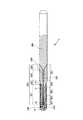
図1は、ガイドワイヤの参考例を示す縦断面図、図2は、図1に示すガイドワイヤにおける第1ワイヤと第2ワイヤとを接続する手順を示す図である。なお、説明の都合上、図1および図2中の右側を「基端」、左側を「先端」という。また、図1および図2中では、見易くするため、ガイドワイヤの長さ方向を短縮し、ガイドワイヤの太さ方向を誇張して模式的に図示しており、長さ方向と太さ方向の比率は実際とは大きく異なる。 FIG. 1 is a longitudinal sectional view showing a reference example of a guide wire, and FIG. 2 is a diagram showing a procedure for connecting a first wire and a second wire in the guide wire shown in FIG. For convenience of explanation, the right side in FIGS. 1 and 2 is referred to as “base end”, and the left side is referred to as “tip”. Further, in FIG. 1 and FIG. 2, the length direction of the guide wire is shortened and the thickness direction of the guide wire is exaggerated for the sake of clarity. The ratio is very different from the actual.
図1に示すガイドワイヤ1は、カテーテルに挿入して用いられるカテーテル用ガイドワイヤであって、先端側に配置された第1ワイヤ2と、第1ワイヤ2の基端側に配置された第2ワイヤ(基端側ワイヤ)3と、螺旋状のコイル4とを有している。ガイドワイヤ1の全長は、特に限定されないが、200〜5000mm程度であるのが好ましい。 A
第2ワイヤ3は、弾性を有する線材である。第2ワイヤ3の長さは、特に限定されないが、200〜4800mm程度であるのが好ましい。 The
第2ワイヤ3は、比較的弾性率(ヤング率(縦弾性係数)、剛性率(横弾性係数)、体積弾性率)が大きい材料で構成されている。これにより、第2ワイヤ3に適度な剛性(曲げ剛性、ねじり剛性)が得られ、ガイドワイヤ1がいわゆるコシの強いものとなって押し込み性およびトルク伝達性が向上し、より優れた挿入操作性が得られる。なお、第2ワイヤ3の構成材料は、第1ワイヤ2の管状ワイヤ23の構成材料より弾性率が大きいものである。 The
第2ワイヤ3の構成材料(素材)は、特に限定されず、ステンレス鋼(例えば、SUS304、SUS303、SUS316、SUS316L、SUS316J1、SUS316J1L、SUS405、SUS430、SUS434、SUS444、SUS429、SUS430F、SUS302等のSUS全品種)、ピアノ線、コバルト系合金(コバルト基合金)、擬弾性を示し得る合金(超弾性合金を含む。)などの各種金属材料を用いることができるが、そのなかでも特にステンレス鋼が好ましい。第2ワイヤ3をステンレス鋼で構成することにより、ガイドワイヤ1は、より優れた押し込み性およびトルク伝達性が得られる。 The constituent material (material) of the
第2ワイヤ3の先端には、第1ワイヤ2の基端が連結(接続)されている。第1ワイヤ2は、弾性を有する線材である。第1ワイヤ2の長さは、特に限定されないが、10〜1000mm程度であるのが好ましい。 The proximal end of the
第1ワイヤ2は、弾性を有する管状ワイヤ23と、この管状ワイヤ23を貫くよう設けられた芯材22とを有している。この芯材22は、長手方向に沿ってその外径がほぼ一定である細径の線材であり、管状ワイヤ23の構成材料より弾性率が大きい材料、好ましくは第2ワイヤ3の構成材料とほぼ弾性率が等しい材料、より好ましくは第2ワイヤ3の構成材料と同一の材料(特に、ステンレス鋼)で構成されている。 The
換言すれば、第1ワイヤ2は、第2ワイヤ3の構成材料と同一またはほぼ弾性率が等しい材料(比較的弾性率が高い材料)で構成された細径の芯材22を、芯材22と比較して弾性率が小さい管状ワイヤ23で覆ったような構成とされている。 In other words, the
このような構成により、第1ワイヤ2の剛性を第2ワイヤ3より十分に低くすることができる。その結果、ガイドワイヤ1は、その先端側の部分に十分な曲げに対する柔軟性が得られ、複雑に湾曲・屈曲する血管に対する追従性が向上し、より優れた操作性が得られるとともに、第1ワイヤ2が湾曲・屈曲変形を繰り返しても、第1ワイヤ2に曲がり癖が付き難いので、ガイドワイヤ1の使用中に第1ワイヤ2に曲がり癖が付くことによる操作性の低下を防止することができる。 With such a configuration, the rigidity of the
なお、芯材22は、長手方向に沿って外径が一定の径一定部と、先端方向へ向かって外径が漸減する少なくとも1つのテーパ部(外径漸減部)とを有するものであってもよい。例えば、複数の径一定部と複数のテーパ部とがワイヤ長手方向に沿って交互に形成されているものでもよい。 The core member 22 has a constant diameter portion having a constant outer diameter along the longitudinal direction and at least one tapered portion (outer diameter gradually decreasing portion) whose outer diameter gradually decreases in the distal direction. Also good. For example, a plurality of constant diameter portions and a plurality of tapered portions may be alternately formed along the wire longitudinal direction.
管状ワイヤ23の最大外径をR1[mm]とし、芯材22の平均外径をR2[mm]としたとき、R2/R1は、0.01〜0.5程度であるのが好ましく、0.02〜0.3程度であるのがより好ましい。R2/R1を前記範囲とすることにより、第1ワイヤ2の剛性をより適度なものとすることができ、ガイドワイヤ1の操作性がより向上する。When the maximum outer diameter of the tubular wire 23 is R1 [mm] and the average outer diameter of the core material 22 is R2 [mm], R2 / R1 is about 0.01 to 0.5. Is preferable, and about 0.02 to 0.3 is more preferable. By setting R2 / R1 in the above range, the rigidity of the
図示の構成では、第1ワイヤ2は、その先端部において、管状ワイヤ23が省略され、芯材22が露出した露出部(先端側ワイヤ)221が形成されている。すなわち、露出部221は、比較的弾性率が高い材料のみで構成されており、これにより、リシェイプ可能となっている。ここで、「リシェイプ可能」とは、線材を所望の形状に曲げてその形状を維持できることを言う。 In the configuration shown in the drawing, the
ガイドワイヤ1は、通常、血管分岐を選択するために、医師がガイドワイヤ1の先端部を所望の形状に曲げて使用することが多いが、このようにガイドワイヤ1に露出部221を設けることにより、ガイドワイヤ1の先端部のリシェイプ(形状付け)を容易かつ確実に行うことができる。その結果、ガイドワイヤ1を生体内に挿入する操作の際の操作性が格段に向上する。 The
この露出部221の長さ(第1ワイヤ2の先端部における芯材22の露出長さ)は、特に限定されないが、5〜200mm程度であるのが好ましく、10〜150mm程度であるのがより好ましい。露出部221の長さが長すぎると、芯材22の構成材料等によっては、ガイドワイヤ1の操作性が低下するおそれがあり、一方、露出部221の長さが短すぎると、ガイドワイヤ1の先端部のリシェイプが困難となるおそれがある。 The length of the exposed portion 221 (the exposed length of the core material 22 at the tip of the first wire 2) is not particularly limited, but is preferably about 5 to 200 mm, more preferably about 10 to 150 mm. preferable. If the length of the exposed
また、図示の構成では、管状ワイヤ23は、その基端から所定長さは外径が一定であり、途中から先端方向へ向かって(先端側において)外径が漸減している。この部分を外径漸減部(テーパ部)15と言う。このような外径漸減部15を有することにより、第1ワイヤ2の剛性(曲げ剛性、ねじり剛性)を先端方向に向かって徐々に減少させることができ、その結果、ガイドワイヤ1は、先端部に良好な柔軟性を得て、血管への追従性、安全性が向上すると共に、折れ曲がり等も防止することができる。 In the illustrated configuration, the tubular wire 23 has a constant outer diameter for a predetermined length from the base end, and the outer diameter gradually decreases from the middle toward the distal end (on the distal end side). This portion is referred to as an outer diameter gradually decreasing portion (tapered portion) 15. By having the outer diameter gradually decreasing portion 15 as described above, the rigidity (bending rigidity, torsional rigidity) of the
図示の構成では、外径漸減部15は管状ワイヤ23の一部に形成されているが、管状ワイヤ23の全体が外径漸減部15を構成していてもよい。また、外径漸減部15のテーパ角度(外径の減少率)は、ワイヤ長手方向に沿って一定でも、長手方向に沿って変化する部位があってもよい。例えば、テーパ角度(外径の減少率)が比較的大きい箇所と比較的小さい箇所とが複数回交互に繰り返して形成されているようなものでもよい。 In the illustrated configuration, the outer diameter gradually decreasing portion 15 is formed in a part of the tubular wire 23, but the entire tubular wire 23 may constitute the outer diameter gradually decreasing portion 15. In addition, the taper angle (outer diameter reduction rate) of the outer diameter gradually decreasing portion 15 may be constant along the longitudinal direction of the wire, or there may be a portion that varies along the longitudinal direction. For example, a portion in which a taper angle (an outer diameter reduction rate) and a relatively small portion are alternately formed a plurality of times may be used.
また、管状ワイヤ23は、外径漸減部15の途中または外径漸減部15より先端側に、外径が長手方向に沿って一定の部分があってもよい。例えば、管状ワイヤ23は、先端方向へ向かって外径が漸減するテーパ状のテーパ部が長手方向に沿って複数箇所に形成され、これらのテーパ部とテーパ部との間に外径が長手方向に沿って一定の部分が形成されているようなものでもよい。このような場合でも、前記と同様の効果が得られる。 Further, the tubular wire 23 may have a portion where the outer diameter is constant along the longitudinal direction in the middle of the outer diameter gradually decreasing portion 15 or on the tip side of the outer diameter gradually decreasing portion 15. For example, the tubular wire 23 is formed with a plurality of taper-shaped taper portions whose outer diameters gradually decrease in the distal direction along the longitudinal direction, and the outer diameter is in the longitudinal direction between the taper portions and the taper portions. A certain part may be formed along the surface. Even in such a case, the same effect as described above can be obtained.
また、図示の構成と異なり、外径漸減部15の基端が第2ワイヤ3の途中に位置する、すなわち、外径漸減部15が第1ワイヤ2と第2ワイヤ3の境界(連結部:溶接部14)を跨って形成された構成でもよい。 Further, unlike the illustrated configuration, the proximal end of the outer diameter gradually decreasing portion 15 is located in the middle of the
このような管状ワイヤ23の構成材料は、芯材22の構成材料より弾性率が小さいものであれば特に限定されず、例えば、ステンレス鋼などの各種金属材料を使用することができるが、そのなかでも特に、擬弾性を示す合金(以下、擬弾性合金という)が好ましい。 The constituent material of the tubular wire 23 is not particularly limited as long as it has an elastic modulus smaller than that of the constituent material of the core material 22. For example, various metal materials such as stainless steel can be used. However, an alloy exhibiting pseudoelasticity (hereinafter referred to as pseudoelastic alloy) is particularly preferable.
擬弾性合金には、引張りによる応力−ひずみ曲線のいずれの形状も含み、As、Af、Ms、Mf等の変態点が顕著に測定できるものも、できないものも含み、応力により大きく変形(歪)し、応力の除去により元の形状にほぼ戻るものは全て含まれる。管状ワイヤ23の構成材料は、超弾性合金がより好ましい。 Pseudoelastic alloys include any shape of stress-strain curve due to tension, including those that can measure the transformation point of As, Af, Ms, Mf, etc., and those that cannot be measured. However, everything that returns to its original shape by removing stress is included. The constituent material of the tubular wire 23 is more preferably a superelastic alloy.
超弾性合金は、比較的柔軟であるとともに、復元性があり、曲がり癖が付き難いので、管状ワイヤ23を超弾性合金で構成することにより、ガイドワイヤ1は、その先端側の部分(第1ワイヤ2)に十分な柔軟性と曲げに対する復元性が得られ、複雑に湾曲・屈曲する血管に対する追従性が向上し、より優れた操作性が得られるとともに、第1ワイヤ2が湾曲・屈曲変形を繰り返しても、第1ワイヤ2に復元性により曲がり癖が付かないので、ガイドワイヤ1の使用中に第1ワイヤ2に曲がり癖が付くことによる操作性の低下を防止することができる。 The superelastic alloy is relatively flexible, has a resilience, and is difficult to bend. Therefore, the
超弾性合金の好ましい組成としては、49〜52原子%NiのNi−Ti合金等のNi−Ti系合金、38.5〜41.5重量%ZnのCu−Zn合金、1〜10重量%XのCu−Zn−X合金(Xは、Be、Si、Sn、Al、Gaのうちの少なくとも1種)、36〜38原子%AlのNi−Al合金等が挙げられる。このなかでも特に好ましいものは、上記のNi−Ti系合金である。 The preferred composition of the superelastic alloy is Ni-Ti alloy such as Ni-Ti alloy of 49-52 atomic% Ni, Cu-Zn alloy of 38.5-41.5 wt% Zn, 1-10 wt% X Cu-Zn-X alloy (X is at least one of Be, Si, Sn, Al, and Ga), 36-38 atomic% Al-Ni-Al alloy, and the like. Of these, the Ni-Ti alloy is particularly preferable.
また、図示の構成では、管状ワイヤ23を超弾性合金で構成し、芯材22および第2ワイヤ3をステンレス鋼で構成することが特に好ましい。これにより、ガイドワイヤ1は、先端側の部分が優れた柔軟性を有するとともに、基端側の部分が剛性(曲げ剛性、ねじり剛性)に富んだものとなる。その結果、ガイドワイヤ1は、優れた押し込み性やトルク伝達性を得て良好な操作性を確保しつつ、先端側においては良好な柔軟性、復元性を得て血管への追従性が向上する。 In the illustrated configuration, it is particularly preferable that the tubular wire 23 is made of a superelastic alloy, and the core member 22 and the
コイル4は、線材(細線)を螺旋状に巻回してなる部材であり、少なくとも露出部221(本実施形態では、露出部221および管状ワイヤ23の先端部)を覆うように設置されている。図示の構成では、第1ワイヤ2の先端側の部分は、コイル4の内側のほぼ中心部に挿通されている。また、第1ワイヤ2の先端側の部分は、コイル4の内面と非接触で挿通されている。第1ワイヤ2と第2ワイヤ3との連結部(溶接部14)は、コイル4の基端より基端側に位置している。 The coil 4 is a member formed by spirally winding a wire (thin wire), and is installed so as to cover at least the exposed portion 221 (in this embodiment, the exposed
なお、図示の構成では、コイル4は、外力を付与しない状態で、螺旋状に巻回された線材同士の間にやや隙間が空いているが、図示と異なり、外力を付与しない状態で、螺旋状に巻回された線材同士が隙間なく密に配置されていてもよい。 In the configuration shown in the figure, the coil 4 has a slight gap between the spirally wound wires in a state where no external force is applied, but unlike the illustration, the coil 4 is spiraled in a state where no external force is applied. Wires wound in a shape may be densely arranged without a gap.
コイル4は、金属材料で構成されているのが好ましい。コイル4を構成する金属材料としては、例えば、ステンレス鋼、超弾性合金、コバルト系合金(コバルト基合金)や、金、白金、タングステン等の貴金属またはこれらを含む合金等が挙げられる。特に、貴金属のようなX線不透過材料で構成した場合には、ガイドワイヤ1にX線造影性が得られ、X線透視下で先端部の位置を確認しつつ生体内に挿入することができ、好ましい。また、コイル4は、その先端側と基端側とを異なる材料で構成してもよい。例えば、先端側をX線不透過材料のコイル、基端側をX線を比較的透過する材料(ステンレス鋼など)のコイルにて各々構成してもよい。なお、コイル4の全長は、特に限定されないが、5〜500mm程度であるのが好ましい。 The coil 4 is preferably made of a metal material. Examples of the metal material constituting the coil 4 include stainless steel, superelastic alloy, cobalt-based alloy (cobalt-based alloy), noble metals such as gold, platinum, and tungsten, and alloys containing these. In particular, when the
コイル4の基端部および先端部は、それぞれ、固定材料11および12により第1ワイヤ2(管状ワイヤ23および芯材22)に固定されている。また、コイル4の中間部(先端寄りの位置)は、固定材料13により第1ワイヤ2(芯材22)に固定されている。固定材料11、12および13は、半田(ろう材)で構成されている。なお、固定材料11、12および13は、半田に限らず、接着剤でもよい。また、コイル4の固定方法は、固定材料によるものに限らず、例えば、溶接でもよい。また、血管内壁の損傷を防止するために、固定材料12の先端面は、丸みを帯びているのが好ましい。 The proximal end portion and the distal end portion of the coil 4 are fixed to the first wire 2 (tubular wire 23 and core material 22) by fixing
図示の構成では、このようなコイル4が設置されていることにより、第1ワイヤ2は、コイル4に覆われて接触面積が少ないので、摺動抵抗を低減することができ、よって、ガイドワイヤ1の操作性がより向上する。 In the illustrated configuration, since the coil 4 is installed, the
なお、図示の構成の場合、コイル4は、線材の横断面が円形のものを用いているが、これに限らず、線材の断面が例えば楕円形、四角形(特に長方形)等のものであってもよい。 In the case of the illustrated configuration, the coil 4 has a circular cross section of the wire. However, the present invention is not limited to this, and the cross section of the wire is, for example, an ellipse or a quadrangle (particularly a rectangle). Also good.
ガイドワイヤ1において、第1ワイヤ2と第2ワイヤ3とは、溶接により互いに一体的に連結(固定)されている。これにより、第1ワイヤ2と第2ワイヤ3との溶接部(連結部)14は、高い結合強度(接合強度)が得られ、よって、ガイドワイヤ1は、溶接部14の破損、損傷を確実に防止することができ、高い安全性が得られる。また、溶接部14の強度低下による弊害、例えば、溶接部14で折れ曲がりを生じたり、第2ワイヤ3からのねじりトルクや押し込み力が第1ワイヤ2に伝達されにくくなったりするような弊害が生じるのも確実に防止することができる。 In the
なお、第2ワイヤ3と芯材22とは、同一または同種の材料により一体的に形成されていてもよい。 In addition, the
また、溶接部14の外周部は、例えば後述する手順<3>等の方法により、実質的に平滑とされているのが好ましい。 Moreover, it is preferable that the outer peripheral part of the
なお、第1ワイヤ2と第2ワイヤ3とは、第1ワイヤ2の少なくとも管状ワイヤ23と第2ワイヤ3とが溶接されているものであってもよい。この場合、例えば、芯材22と第2ワイヤ3とを一体的に形成し、芯材22の外周に管状ワイヤ23を配置して、管状ワイヤ23の基端と第2ワイヤ3の先端とを溶接により連結する構成とすることができる。 Note that the
また、図示の構成では、第1ワイヤ2の第2ワイヤ3に対する接続端面21と、第2ワイヤ3の第1ワイヤ2に対する接続端面31とは、それぞれ、ガイドワイヤ1の軸方向(長手方向)に対しほぼ垂直な平面になっているが、これにより、接続端面21、31を形成するための加工が極めて容易であり、ガイドワイヤ1の製造工程を複雑化することなく上記効果を達成することができる。 In the illustrated configuration, the
なお、図示の構成と異なり、接続端面21、31は、両ワイヤの軸方向(長手方向)に垂直な平面に対し傾斜していてもよく、また、凹面または凸面になっていてもよい。例えば、後述する図3の実施形態の第2テーパ部634のように、接続端面21、31は、先端方向に向かって外径が漸減するテーパ面であってもよい。 Note that, unlike the illustrated configuration, the connection end faces 21 and 31 may be inclined with respect to a plane perpendicular to the axial direction (longitudinal direction) of both wires, or may be concave or convex. For example, like the
第1ワイヤ2と、第2ワイヤ3との溶接の方法としては、特に限定されず、例えば、レーザを用いたスポット溶接、バットシーム溶接等の突き合わせ抵抗溶接などが挙げられるが、突き合わせ抵抗溶接であるのが好ましい。これにより、溶接部14は、より高い結合強度が得られる。 The method for welding the
以下、図2を参照して、第1ワイヤ2と第2ワイヤ3とを突き合わせ抵抗溶接の一例であるバットシーム溶接により接合する場合の手順について説明する。同図には、第1ワイヤ2と第2ワイヤ3とをバットシーム溶接により接合する場合の手順<1>〜<3>が示されている。 Hereinafter, with reference to FIG. 2, the procedure in the case of joining the
手順<1>では、図示しないバット溶接機に固定(装着)された第1ワイヤ2と第2ワイヤ3とが示される。 In the procedure <1>, the
手順<2>にて、第1ワイヤ2と第2ワイヤ3とは、バット溶接機によって、所定の電圧を印加されながら第1ワイヤ2の基端側の接続端面21と第2ワイヤ3の先端側の接続端面31とが加圧接触される。この加圧接触により、接触部分には溶融層が形成され、第1ワイヤ2と第2ワイヤ3とは強固に接続される。 In the procedure <2>, the
手順<3>にて、加圧接触することによって変形された接続箇所(溶接部14)の突出部分を除去(削除)する。これにより、溶接部14の外周は、実質的に平滑とされる。なお、突出部分の除去方法は、例えば、研削、研磨、エッチング等の化学処理が挙げられる。 In the procedure <3>, the protruding portion of the connection portion (welded portion 14) deformed by the pressure contact is removed (deleted). Thereby, the outer periphery of the
次いで、管状ワイヤ23の接続箇所(溶接部14)より先端側の部位を研削または研磨して外径が先端方向に向かって漸減する外径漸減部15を形成するとともに、第1ワイヤ2の先端部において芯材22を露出させ、露出部221を形成する。 Next, the distal end side of the
なお、外径漸減部15の基端を溶接部14より基端側とする場合には、手順<3>を省略して、外径漸減部15を形成する本手順(本工程)を行ってもよい。 When the proximal end of the outer diameter gradually decreasing portion 15 is set to the proximal end side from the welded
なお、第1ワイヤ2(芯材22および管状ワイヤ23)と第2ワイヤ3との接合は、溶接によるものが好ましいが、例えば、管状部材内に挿入しろう材を充填して固定するなど任意の方法を用いることもできる。 The first wire 2 (the core material 22 and the tubular wire 23) and the
以上のようなガイドワイヤ1は、その外周面(外表面)の全部または一部を覆う合成樹脂の図示しない被覆(プラスティックジャケット)を有していてもよい。これにより、ガイドワイヤ1とともに用いられるカテーテルの内壁との摩擦が低減されて摺動性が向上し、カテーテル内でのガイドワイヤ1の操作性がより良好なものとなる。このような被覆の構成材料としては、例えば、ポリエチレン、ポリ塩化ビニル、ポリエステル、ポリプロピレン、ポリアミド、ポリウレタン、ポリスチレン、ポリカーボネート、フッ素系樹脂(PTFE、ETFE等)、シリコーン樹脂、その他各種のエラストマー、またはこれらの複合材料が好ましく用いられる。特に、管状ワイヤ23と同等またはそれ以下の可撓性、柔軟性を有するものが好ましい。また、このような被覆を設ける個所は、特に限定されず、例えば、ガイドワイヤ1のほぼ全体に設けられていても良く、先端側の部分(第1ワイヤ2およびコイル4の外周面)のみに設けられていても良い。 The
また、ガイドワイヤ1の外周面の全部または一部には、ガイドワイヤ1とともに用いられるカテーテルの内壁との接触により発生する摩擦を抑える処理が施されていてもよい。これにより、カテーテル内壁との摩擦が抑えられ、カテーテル内でのガイドワイヤ1の操作性は、より良好なものとなる。この処理としては、例えば、ガイドワイヤ1の外周面に、親水性材料または疎水性材料による被膜(図示せず)を設けることができる。 Further, all or a part of the outer peripheral surface of the
この被膜を構成する親水性材料としては、例えば、セルロース系高分子物質、ポリエチレンオキサイド系高分子物質、無水マレイン酸系高分子物質(例えば、メチルビニルエーテル−無水マレイン酸共重合体のような無水マレイン酸共重合体)、アクリルアミド系高分子物質(例えば、ポリアクリルアミド、ポリグリシジルメタクリレート−ジメチルアクリルアミド(PGMA−DMAA)のブロック共重合体)、水溶性ナイロン、ポリビニルアルコール、ポリビニルピロリドン等が挙げられる。また、被膜を構成する疎水性材料としては、例えば、ポリテトラフルオロエチレン等のフッ素系樹脂、シリコーン系の材料等が挙げられる。 Examples of the hydrophilic material constituting the coating include cellulose-based polymer materials, polyethylene oxide-based polymer materials, and maleic anhydride-based polymer materials (for example, maleic anhydride such as methyl vinyl ether-maleic anhydride copolymer). Acid copolymer), acrylamide polymer substances (for example, polyacrylamide, polyglycidyl methacrylate-dimethylacrylamide (PGMA-DMAA) block copolymer), water-soluble nylon, polyvinyl alcohol, polyvinylpyrrolidone, and the like. Moreover, as a hydrophobic material which comprises a film, fluororesins, such as polytetrafluoroethylene, a silicone type material, etc. are mentioned, for example.
図3は、本発明のガイドワイヤの実施形態を示す縦断面図である。なお、説明の都合上、図3中の右側を「基端」、左側を「先端」という。また、図3中では、見易くするため、ガイドワイヤの長さ方向を短縮し、ガイドワイヤの太さ方向を誇張して模式的に図示しており、長さ方向と太さ方向の比率は実際とは大きく異なる。 FIG. 3 is a longitudinal sectional view showing an embodiment of the guide wire of the present invention. For convenience of explanation, the right side in FIG. 3 is referred to as “base end” and the left side is referred to as “tip”. Further, in FIG. 3, for the sake of easy understanding, the length direction of the guide wire is shortened and the thickness direction of the guide wire is exaggerated, and the ratio of the length direction to the thickness direction is actually shown. Is very different.
以下、図3に基づいて本発明のガイドワイヤの実施形態を説明するが、主に前述した参考例と相違する点について説明し、同様の事項についてはその説明を省略する。 Hereinafter, an embodiment of the guide wire according to the present invention will be described with reference to FIG. 3. However, the difference from the reference example described above will be mainly described, and description of similar matters will be omitted.
図3に示すガイドワイヤ1は、先端側に配置された先端側ワイヤ(前記露出部221に相当)230と、該先端側ワイヤ230の基端側に配置された中間ワイヤ600と、該中間ワイヤ600の基端側に配置された基端側ワイヤ(前記第2ワイヤ3に相当)300とを有している。 The
先端側ワイヤ230は、後述する中間ワイヤ600の内層630が先端方向に延長されて形成されたものであり、リシェイプ可能な金属材料で構成されている。一般に、ガイドワイヤでは、誘導するカテーテルの先端部を血管形状に対応させたり、血管分岐を円滑に誘導したりするために、医師などがガイドワイヤの先端部を所望の形状に曲げて使用することが多い。このようにガイドワイヤの先端部を所望の形状に曲げることを、リシェイプ(形状付け)と言うが、本発明のガイドワイヤ1では、先端側ワイヤ230がリシェイプに適したものとなっている。 The distal
リシェイプ可能な金属材料としては、例えば、ステンレス鋼、コバルト系合金(コバルト基合金)が挙げられる。 Examples of the reshaped metal material include stainless steel and a cobalt-based alloy (cobalt-based alloy).
先端側ワイヤ230は、主に、平板状をなす平板部232で構成されている。この平板部232の横断面形状は、実施的に長方形であるが、例えば、楕円、長円、台形等の他の形状であってもよい。また、平板部232の横断面形状は、先端側ワイヤ230の長手方向に沿って一定でも、変化する部位があってもよい。例えば、後者の場合、先端方向に向かって平板部232の幅が漸増または漸減するような部位があってもよい。 The distal
なお、先端側ワイヤ230の形状は、前述した平板状に限らず、その他例えば線状(棒状)であってもよい。 In addition, the shape of the distal
このような先端側ワイヤ230の先端部は、前記と同様の固定材料12によりコイル4の先端部と固定されている。 The distal end portion of the distal
中間ワイヤ600は、内層(芯材)630と、該内層630の外周面を囲むように形成された外層(被覆層)620とで構成されている。内層630および外層620は、それぞれ、長手方向に沿ってその横断面形状(外径等)が変化している。 The
内層630は、先端側ワイヤ230を構成する金属材料と同一または同種の材料で構成されているのが好ましい。特に、内層630と先端側ワイヤ230とは、連続した一体の金属線材で構成されていること、すなわち、先端側ワイヤ230は内層630が先端方向に延長されて形成されたものであるのが好ましい。これにより、中間ワイヤ600は先端側に向って滑らかな物性移行となり、良好な柔軟性を得て、血管への追従性、安全性が向上すると共に、折れ曲がり等も防止できるという効果が得られる。 The
また、内層630は、基端側ワイヤ300を構成する金属材料と同一または同種の材料で構成されているのが好ましい。特に、内層630と基端側ワイヤ300とは、連続した一体の金属線材で構成されていること、すなわち、内層630は、基端側ワイヤ300が先端方向に延長されて形成されたものであるのが好ましい。これにより、基端側ワイヤ300から先端に向って滑らかな物性移行となり、良好な柔軟性を得て、血管への追従性、安全性が向上すると共に、折れ曲がり等も防止できるという効果が得られる。 Further, the
このような内層630は、外層620の構成材料より剛性の高い材料で構成されているのが好ましい。このような材料としては、例えば、ステンレス鋼、コバルト系合金(コバルト基合金)が挙げられる。 Such an
内層630は、先端方向に向かってその外径が漸減する少なくとも1つのテーパ部を有しているのが好ましく、当該テーパ部を複数有しているのがより好ましい。 The
内層630は、図1に示す参考例で述べたのと同様に、長手方向に沿って外径が一定の径一定部と、先端方向へ向かって外径が漸減するテーパ部(外径漸減部)とを有し、これらが交互に複数づつ形成されている。このような構成とすることにより、中間ワイヤ600の剛性(曲げ剛性、ねじり剛性)を先端方向に向かって徐々に減少させることができ、その結果、ガイドワイヤ1は、先端部に良好な柔軟性を得て、血管への追従性、安全性が向上すると共に、折れ曲がり等も防止することができる。 As described in the reference example shown in FIG. 1, the
内層630の第1径一定部631は、コイル4の内部に位置している。第1テーパ部632は、第1径一定部631の基端から基端方向に延びている。第2径一定部633は、第1テーパ部632の基端から基端方向に延びている。第2テーパ部634は、第2径一定部633の基端から基端方向に延びている。第2テーパ部634の基端は、基端側ワイヤ300の先端と連続し、一体化されている。 The first
第2径一定部633の外径は、基端側ワイヤ300の外径より小さく、第1径一定部631の外径は、第2径一定部633の外径より小さい。また、第1テーパ部632と第2テーパ部634のテーパ角度は、特に限定されず、これらは同一でも異なっていてもよい。 The outer diameter of the second
外層(前記管状ワイヤ23に相当)620は、擬弾性を示し得る合金で構成されているのが好ましい。当該合金は、擬弾性を示す合金の組成を備えるものであればよく、典型的な例としては、Ni−Ti系合金が挙げられる。このような構成としたことにより、先端側の部分に十分な柔軟性と曲げに対する復元性が得られ、複雑に湾曲、屈曲する血管に対する追従性が向上し、より優れた操作性が得られるとともに、湾曲、屈曲変形を繰り返しても、外層620の復元性により曲がり癖が付かないので、曲がり癖が付くことによる操作性の低下を防止できるという効果が得られる。 The outer layer (corresponding to the tubular wire 23) 620 is preferably made of an alloy that can exhibit pseudoelasticity. The alloy should just have the composition of the alloy which shows pseudoelasticity, and a Ni-Ti type alloy is mentioned as a typical example. By adopting such a configuration, sufficient flexibility and resilience to bending can be obtained at the distal end side, follow-up performance to a blood vessel that is curved and bent in a complicated manner is improved, and more excellent operability is obtained. Even if the bending and bending deformation are repeated, the bend crease is not attached due to the resilience of the
また、外層620は、擬弾性合金以外の材料で構成されていてもよく、その場合、内層630を構成する材料より剛性の低い材料で構成されているのが好ましい。 Further, the
外層620は、図1に示す参考例で述べたのと同様に、長手方向に沿って外径が一定の径一定部と、先端方向へ向かって外径が漸減するテーパ部(外径漸減部)とを有し、これらが交互に複数づつ形成されている。このような構成とすることにより、前述した内層630の先端方向への外径変化と相まって、中間ワイヤ600の剛性(曲げ剛性、ねじり剛性)を先端方向に向かって徐々に減少させることができ、その結果、ガイドワイヤ1は、先端部に良好な柔軟性を得て、血管への追従性、安全性が向上すると共に、折れ曲がり等も防止することができる。 As described in the reference example shown in FIG. 1, the
外層620の第1径一定部621の先端は、先端側ワイヤ230の基端付近に達している。第1テーパ部622は、第1径一定部621の基端から基端方向に延びている。第2径一定部623は、第1テーパ部622の基端から基端方向に延びている。第1径一定部621、第1テーパ部622および第2径一定部623は、コイル4の内部に位置している。第2テーパ部624は、第2径一定部623の基端から基端方向に延びている。第3径一定部625は、第2テーパ部624の基端から基端方向に延びている。 The distal end of the first
第3径一定部625の外径は、基端側ワイヤ300の外径とほぼ等しく、第3径一定部625の基端部外周面と、基端側ワイヤ300の先端部外周面とは、段差のない滑らかな連続面を形成している。 The outer diameter of the third diameter
第2径一定部623の外径は、基端側ワイヤ300および第3径一定部625の外径より小さく、第1径一定部621の外径は、第2径一定部623の外径より小さい。また、第1テーパ部622と第2テーパ部624のテーパ角度は、特に限定されず、これらは同一でも異なっていてもよい。 The outer diameter of the second
ガイドワイヤ1を冠動脈へ挿入する場合、ガイドワイヤ1の第3径一定部625に相当する部位は、大動脈弓付近に留置されるため、ガイドワイヤ1が湾曲した状態でもトルクを十分に伝達し得る特性が望ましい。この点に関し、本発明のガイドワイヤ1は、外層620が擬弾性を示し得る合金で構成されているので、湾曲形状とされたときでも曲がり癖がつき難く(すなわち、形状復元性を維持することができ)、耐キンク性に優れ、しかも、外層620より剛性の高い材料で構成された内層630が軸方向に存在するので、トルク伝達性に優れる。 When the
ガイドワイヤ1の第2テーパ部634に相当する部位においては、外層620の外径は先端方向に向かってほぼ一定であるが、内層630の外径は先端方向に向かって徐々に減少しているので、中間ワイヤ600の全横断面積に対する外層620の横断面積の占める割合が徐々に増大し、その結果、ガイドワイヤ1全体としては、先端方向に向かって柔軟性が徐々に増大している。 In the portion corresponding to the
外層620の第2テーパ部624は、内層630の第1テーパ部632を包含している。また、第2テーパ部624と第1テーパ部632は、それらの一部が重なっていてもよい。 The second
第2テーパ部624と第1テーパ部632の長さは、同一でも異なっていてもよいが、異なっているのが好ましい。図3に示す構成では、第2テーパ部624の方が第1テーパ部632より長い。 The lengths of the second
中間ワイヤ600の少なくとも一部において、内層630における先端方向への外径の減少率や、外層620における先端方向への外径の減少率は、異なる部分を有することが好ましい。 In at least a part of the
また、内層630における先端方向への外径の減少率(テーパ角度)の方が外層620のそれよりも小さいことが好ましい。このような部分としては、内層630の第1テーパ部632や外層620の第1テーパ部622が挙げられる。このような内層630と外層620の先端方向への外径の減少率(テーパ角度)が異なる部分は、少なくとも2ヶ所あるのが好ましい。 In addition, it is preferable that the reduction rate (taper angle) of the outer diameter in the distal direction in the
また、中間ワイヤ600は、第2テーパ部634のように、内層630における先端方向への外径の減少率の方が外層620における先端方向への外径の減少率よりも大きい部分を有するのが好ましい。第2テーパ部634においては、外層620は実質的に外径が一定であるため、外径の減少率は0であり、内層630は、先端方向に向かって所定の割合で外径が減少している。 Further, like the second
ガイドワイヤ1を冠動脈へ挿入する場合、ガイドワイヤ1の第2径一定部623に相当する部位は、上行大動脈から冠動脈内に位置するため、ガイドワイヤ1が曲がりくねった冠動脈内でも押し込み性やトルク伝達性に優れ、かつ、塑性変形し難いという特性を持つことが望ましい。 When the
この点に関し、本発明のガイドワイヤ1は、外層620が擬弾性合金で構成されているので、湾曲形状とされたときでも曲がり癖がつき難く(すなわち、形状復元性を維持することができ)、耐キンク性に優れ、しかも、外層620より剛性の高い材料で構成された内層630が軸方向に存在するので、押し込み性およびトルク伝達性にも優れている。 In this regard, the
中間ワイヤ600において、内層630の横断面積は、中間ワイヤ600の全横断面積の約80%以下であることが好ましく、10〜50%程度であるのがより好ましい。なお、この値は、中間ワイヤ600の全長における平均値である。この値が80%を超えると、内層630の構成材料の特性、特に塑性変形し易い特性がより明確に現れて、全体として剛性が高く、または、曲がり癖がつき易い傾向となる。 In the
外層620の第1径一定部621は、内層630の第1径一定部631に包含されている。また、第1径一定部621と第1径一定部631は、それらの一部が重なっていてもよい。 The first
外層620の第2径一定部623は、内層630の第1径一定部631に包含されている。また、第2径一定部623と第1径一定部631は、それらの一部が重なっていてもよい。 The second
また、第2径一定部623の長さは、コイル4の全長よりも短いのが好ましい。コイル4の内部に位置する外層620の径一定部(第2径一定部623)の長さは、先端側ワイヤ230よりも長いことが好ましい。 The length of the second diameter
外層620の第1テーパ部622は、内層630の第1径一定部631に包含されている。また、第1テーパ部622と第1径一定部631は、それらの一部が重なっていてもよい。 The first
図3に示す構成では、外層620の第1径一定部621の先端は、内層630の第1径一定部631の先端とほぼ一致している。ただし、本発明では、第1径一定部621の先端は、第1径一定部631の先端と一致していなくてもよい。すなわち、第1径一定部621の先端より先端方向に第1径一定部631が延びていてもよい。この場合、第1径一定部631は、外層620で覆われていない部分が存在することとなり、この部分は、先端側ワイヤ230の一部と呼ぶこともできる。 In the configuration shown in FIG. 3, the tip of the first
第1径一定部621においては、半田(ろう材)、接着剤等の固定材料13によりコイル4と固定されている。 The first
なお、固定する部分(固定材料を付与する部分)だけ外層620が存在しないようにしてもよい。この場合には、内層630の露出部分が固定材料13によりコイル4と固定されることとなるが、内層630の構成材料が固定材料13との結合力が大きい材料である場合、より強固な固定が実現でき、好ましい。 Note that the
また、図1に示す構成と同様に、固定材料13よりも基端側に外層620(管状ワイヤ23)の先端が位置していてもよく、この場合も前記と同様である。この場合にも、内層630の第1径一定部631と固定材料13とが強い結合力で結合し、強固な固定が可能となる。 Further, similarly to the configuration shown in FIG. 1, the distal end of the outer layer 620 (tubular wire 23) may be located closer to the proximal end side than the fixing
外層620および内層630の形成方法は、特に限定されず、例えば、次のような方法により形成することができる。 The formation method of the
まず、内層630を構成する金属材料よりなるワイヤを、所望の外径やテーパ形状になるように伸線加工、機械研磨、化学研磨等を施し、第1径一定部631、第1テーパ部632、第2径一定部633および第2テーパ部634を形成する。 First, a wire made of a metal material constituting the
なお、基端側ワイヤ300、内層630および先端側ワイヤ230が同一材料による一体化物である場合、基端側ワイヤ300としての金属線材を用意し、その先端側、すなわち内層630および先端側ワイヤ230となるべき部分に対し、伸線加工、プレス加工、機械研磨、化学研磨等を施して、所望形状の内層630(第1径一定部631、第1テーパ部632、第2径一定部633および第2テーパ部634)および先端側ワイヤ230とする。 When the proximal
次に、内層630の全長(または一部を除く部位)の外周面に対し、外層620を構成する金属材料(例えばNi−Ti合金)を例えば蒸着、スパッタリング、イオンプレーティング等の乾式メッキ法(気相成膜法)または湿式メッキ法あるいは金属溶着等により被覆形成し、その後、所望の外径やテーパ形状になるように機械研磨、化学研磨等を施し、第1径一定部621、第1テーパ部622、第2径一定部623、第2テーパ部624および第3径一定部625を形成する。 Next, a metal material (for example, Ni—Ti alloy) constituting the
Ni−Ti合金にて構成された外層620の場合、外層620の形成方法にもよるが、その外層620部分に所定の熱処理を施すと、擬弾性または擬弾性に近い特性を発現させる場合がある。 In the case of the
以上のような中間ワイヤ600の基端側には、基端側ワイヤ300が設けられている。基端側ワイヤ300は、先端側ワイヤ230および内層630を構成する材料と同一または同種の材料で構成されているのが好ましい。この材料としては、例えば、ステンレス鋼、コバルト系合金(コバルト基合金)が挙げられる。 The proximal
図4および図5は、それぞれ、本発明のガイドワイヤ1をPTCA術に用いた場合における使用状態を示す図である。 FIG. 4 and FIG. 5 are diagrams each showing a use state when the
図4および図5中、符号40は大動脈弓、符号50は心臓の右冠状動脈、符号60は右冠状動脈開口部、符号70は血管狭窄部である。また、符号30は大腿動脈からガイドワイヤ1を確実に右冠状動脈に導くためのガイディングカテーテル、符号20はその先端部分に拡張・収縮自在なバルーン201を有する狭窄部拡張用のバルーンカテーテルである。 4 and 5,
図4に示すように、ガイドワイヤ1の先端をガイディングカテーテル30の先端から突出させ、右冠状動脈開口部60から右冠状動脈50内に挿入する。さらに、ガイドワイヤ1を進め、先端から右冠状動脈内に挿入し、先端が血管狭窄部70を超えた位置で停止する。これにより、バルーンカテーテル20の通路が確保される。なお、このとき、ガイドワイヤ1の溶接部14(または第2テーパ部634の基端部)は、大動脈弓40の下流側(生体内)に位置している。 As shown in FIG. 4, the distal end of the
次に、図5に示すように、ガイドワイヤ1の基端側から挿通されたバルーンカテーテル20の先端をガイディングカテーテル30の先端から突出させ、さらにガイドワイヤ1に沿って進め、右冠状動脈開口部60から右冠状動脈50内に挿入し、バルーンが血管狭窄部70の位置に到達したところで停止する。 Next, as shown in FIG. 5, the distal end of the
次に、バルーンカテーテル20の基端側からバルーン拡張用の流体を注入して、バルーン201を拡張させ、血管狭窄部70を拡張する。このようにすることによって、血管狭窄部70の血管に付着堆積しているコレステロール等の堆積物は物理的に押し広げられ、血流阻害が解消できる。 Next, a balloon expansion fluid is injected from the proximal end side of the
以上、本発明のガイドワイヤを図示の実施形態について説明したが、本発明は、これに限定されるものではなく、ガイドワイヤを構成する各部は、同様の機能を発揮し得る任意の構成のものと置換することができる。また、任意の構成物が付加されていてもよい。 As mentioned above, although the guide wire of this invention was demonstrated about embodiment of illustration, this invention is not limited to this, Each part which comprises a guide wire is a thing of arbitrary structures which can exhibit the same function. Can be substituted. Moreover, arbitrary components may be added.
図1に示す参考例では、ガイドワイヤは、第1ワイヤにおいて芯材が露出する露出部を有さないもの、すなわち、管状ワイヤが芯材の先端まで設けられたような構成であってもよい。この場合、第1ワイヤの先端部における、管状ワイヤの外径と芯材の外径との比率を適宜設定することにより、ガイドワイヤの先端部のリシェイプ性を確保することができる。 In the reference example shown in FIG. 1, the guide wire may have a configuration in which the first wire does not have an exposed portion where the core material is exposed, that is, the tubular wire is provided up to the tip of the core material. . In this case, the reshapability of the distal end portion of the guide wire can be ensured by appropriately setting the ratio of the outer diameter of the tubular wire and the outer diameter of the core material at the distal end portion of the first wire.
また、図1に示す参考例では、第1ワイヤにおいて、芯材と管状ワイヤとの間には、任意の目的の層(例えば、芯材と管状ワイヤとの密着性を向上し得る中間層)を設けることもできる。 In the reference example shown in FIG. 1, in the first wire, a desired layer (for example, an intermediate layer capable of improving the adhesion between the core material and the tubular wire) between the core material and the tubular wire. Can also be provided.
1 ガイドワイヤ
2 第1ワイヤ
21 接続端面
22 芯材
221 露出部
23 管状ワイヤ
3 第2ワイヤ
31 接続端面
4 コイル
11、12、13 固定材料
14 溶接部
15 外径漸減部
20 バルーンカテーテル
201 バルーン
30 ガイディングカテーテル
40 大動脈弓
50 右冠状動脈
60 右冠状動脈開口部
70 血管狭窄部
230 先端側ワイヤ
232 平板部
300 基端側ワイヤ
600 中間ワイヤ
620 外層
621 第1径一定部
622 第1テーパ部
623 第2径一定部
624 第2テーパ部
625 第3径一定部
630 内層
631 第1径一定部
632 第1テーパ部
633 第2径一定部
634 第2テーパ部DESCRIPTION OF
Claims (6)
Translated fromJapanese前記先端側ワイヤの基端側に配置され、内層と外層とを有する中間ワイヤと、
前記中間ワイヤの基端側に配置され、前記先端側ワイヤを構成する金属材料と同一または同種の材料で構成された線状の基端側ワイヤとを有し、
前記内層は、先端方向に向かってその外径が漸減するテーパ部と、その外径が長手方向に沿ってほぼ一定の径一定部とをそれぞれ複数有し、これらが前記中間ワイヤの長手方向に沿って交互に配置されており、
前記外層は、先端方向に向かってその外径が漸減するテーパ部と、その外径が長手方向に沿ってほぼ一定の径一定部とをそれぞれ複数有し、これらが前記中間ワイヤの長手方向に沿って交互に配置されていることを特徴とするガイドワイヤ。A tip side wire made of a reshapeable metal material disposed on the tip side;
An intermediate wire disposed on the proximal side of the distal wire and having an inner layer and an outer layer;
A linear proximal end wire arranged on the proximal end side of the intermediate wire and made of the same or the same kind of material as the metal material constituting the distal end side wire;
The inner layer has a plurality of taper portions whose outer diameters gradually decrease toward the distal direction, and a plurality of constant diameter constant portions whose outer diameters are substantially constant along the longitudinal direction, and these are in the longitudinal direction of the intermediate wire. Are arranged alternately along the
The outer layer has a plurality of taper portions whose outer diameters gradually decrease toward the distal direction, and a plurality of constant diameter constant portions whose outer diameters are substantially constant along the longitudinal direction, and these are in the longitudinal direction of the intermediate wire. Guidewires arranged alternately along the guide wire.
Priority Applications (1)
| Application Number | Priority Date | Filing Date | Title |
|---|---|---|---|
| JP2008025771AJP2008110266A (en) | 2002-08-09 | 2008-02-05 | Guide wire |
Applications Claiming Priority (2)
| Application Number | Priority Date | Filing Date | Title |
|---|---|---|---|
| JP2002233906 | 2002-08-09 | ||
| JP2008025771AJP2008110266A (en) | 2002-08-09 | 2008-02-05 | Guide wire |
Related Parent Applications (1)
| Application Number | Title | Priority Date | Filing Date |
|---|---|---|---|
| JP2003202641ADivisionJP4116944B2 (en) | 2002-08-09 | 2003-07-28 | Guide wire |
Publications (1)
| Publication Number | Publication Date |
|---|---|
| JP2008110266Atrue JP2008110266A (en) | 2008-05-15 |
Family
ID=39443099
Family Applications (1)
| Application Number | Title | Priority Date | Filing Date |
|---|---|---|---|
| JP2008025771APendingJP2008110266A (en) | 2002-08-09 | 2008-02-05 | Guide wire |
Country Status (1)
| Country | Link |
|---|---|
| JP (1) | JP2008110266A (en) |
Cited By (1)
| Publication number | Priority date | Publication date | Assignee | Title |
|---|---|---|---|---|
| JPWO2021131019A1 (en)* | 2019-12-27 | 2021-07-01 |
Citations (3)
| Publication number | Priority date | Publication date | Assignee | Title |
|---|---|---|---|---|
| JPH09276412A (en)* | 1995-12-04 | 1997-10-28 | Target Therapeutics Inc | Nickel-titanium lubricative medical treatment catheter wire |
| JP2000512691A (en)* | 1997-04-15 | 2000-09-26 | シメッド ライフ システムズ インコーポレイテッド | Improved linear elastic member |
| JP2002095755A (en)* | 2000-07-06 | 2002-04-02 | Japan Lifeline Co Ltd | Medical guidewire |
- 2008
- 2008-02-05JPJP2008025771Apatent/JP2008110266A/enactivePending
Patent Citations (3)
| Publication number | Priority date | Publication date | Assignee | Title |
|---|---|---|---|---|
| JPH09276412A (en)* | 1995-12-04 | 1997-10-28 | Target Therapeutics Inc | Nickel-titanium lubricative medical treatment catheter wire |
| JP2000512691A (en)* | 1997-04-15 | 2000-09-26 | シメッド ライフ システムズ インコーポレイテッド | Improved linear elastic member |
| JP2002095755A (en)* | 2000-07-06 | 2002-04-02 | Japan Lifeline Co Ltd | Medical guidewire |
Cited By (1)
| Publication number | Priority date | Publication date | Assignee | Title |
|---|---|---|---|---|
| JPWO2021131019A1 (en)* | 2019-12-27 | 2021-07-01 |
Similar Documents
| Publication | Publication Date | Title |
|---|---|---|
| JP4203358B2 (en) | Guide wire | |
| JP4138582B2 (en) | Guide wire | |
| JP4138583B2 (en) | Guide wire | |
| JP2008161589A (en) | Guide wire | |
| JP3380691B2 (en) | Guide wire | |
| JP5473677B2 (en) | Guide wire | |
| JP4734015B2 (en) | Guide wire manufacturing method | |
| JP4375951B2 (en) | Guide wire | |
| JP4783343B2 (en) | Guide wire | |
| JP4376048B2 (en) | Guide wire | |
| JP4116944B2 (en) | Guide wire | |
| JP3962652B2 (en) | Guide wire | |
| JP5328835B2 (en) | Guide wire manufacturing method | |
| JP5073713B2 (en) | Guide wire | |
| JP4405252B2 (en) | Medical wire | |
| JP4447597B2 (en) | Guide wire | |
| JP4734029B2 (en) | Guide wire manufacturing method | |
| JP2004065796A (en) | Guide wire | |
| JP2008110266A (en) | Guide wire | |
| JP4138467B2 (en) | Guide wire | |
| JP4455808B2 (en) | Guide wire | |
| JP2004065794A (en) | Guide wire | |
| JP3683236B2 (en) | Guide wire | |
| JP3683237B2 (en) | Guide wire | |
| JP4376073B2 (en) | Guide wire |
Legal Events
| Date | Code | Title | Description |
|---|---|---|---|
| A621 | Written request for application examination | Free format text:JAPANESE INTERMEDIATE CODE: A621 Effective date:20080206 | |
| A977 | Report on retrieval | Free format text:JAPANESE INTERMEDIATE CODE: A971007 Effective date:20101014 | |
| A131 | Notification of reasons for refusal | Free format text:JAPANESE INTERMEDIATE CODE: A131 Effective date:20101019 | |
| A521 | Written amendment | Free format text:JAPANESE INTERMEDIATE CODE: A523 Effective date:20101216 | |
| A02 | Decision of refusal | Free format text:JAPANESE INTERMEDIATE CODE: A02 Effective date:20110329 |