JP2008109306A - Mobile device - Google Patents
Mobile deviceDownload PDFInfo
- Publication number
- JP2008109306A JP2008109306AJP2006289140AJP2006289140AJP2008109306AJP 2008109306 AJP2008109306 AJP 2008109306AJP 2006289140 AJP2006289140 AJP 2006289140AJP 2006289140 AJP2006289140 AJP 2006289140AJP 2008109306 AJP2008109306 AJP 2008109306A
- Authority
- JP
- Japan
- Prior art keywords
- user data
- mobile phone
- rescue
- transmission destination
- control unit
- Prior art date
- Legal status (The legal status is an assumption and is not a legal conclusion. Google has not performed a legal analysis and makes no representation as to the accuracy of the status listed.)
- Pending
Links
Images


Landscapes
- Mobile Radio Communication Systems (AREA)
- Telephone Function (AREA)
- Telephonic Communication Services (AREA)
Abstract
Translated fromJapaneseDescription
Translated fromJapanese本発明は、蓄積されているユーザデータを保護すると同時に、第三者による悪用の防止を行う携帯端末に関するものである。 The present invention relates to a portable terminal that protects stored user data and at the same time prevents abuse by a third party.
近年、携帯端末が普及するとともに多機能化し、住所録、音楽、画像等の様々の情報が記憶されるようになってきている。携帯端末は外に持ち出して使用する機器のため、不注意による紛失、置き忘れ、盗難等により、第三者の手に渡り、記憶していた情報を参照されたり、悪用されたりするおそれがある。 In recent years, mobile terminals have become widespread and multifunctional, and various information such as address books, music, and images have been stored. Since the portable terminal is a device that is taken out and used, there is a risk that the stored information may be referred to or misused by a third party due to inadvertent loss, misplacement, theft, or the like.
ここで、携帯端末の情報を保護する技術が特許文献1に開示されている。この発明は、ユーザが携帯端末を紛失した場合、無線ネットワークを通して当該携帯端末に情報保護命令を送信すると、携帯端末内の情報について所定の情報回収装置への回収と無効化を行うものである。
しかしながら、前記特許文献1の技術では、無線ネットワークのセンター側からセキュリティコントローラーやデータベースシステムを介して情報保護命令が送信され、携帯端末内にある情報を回収するとともに、携帯端末の機密情報処理(端末情報のメモリ消去または偽データへの変換)を行っている。このため、前記特許文献1の技術では、情報の回収にセキュリティコントローラーやデータベース等の仕組みを新設する必要があり、設備投資が必要となる。
また、携帯端末自体を使用することができるかにつき具体的記載がなく、情報を回収し携帯端末の情報の機密情報処理(携帯端末のユーザデータのメモリ消去または偽データへの変換)を行うだけでは、ユーザデータ保護の観点より万全であるとは言い難い。However, in the technique of Patent Document 1, an information protection instruction is transmitted from the center side of the wireless network via a security controller or a database system, and the information in the portable terminal is collected and the confidential information processing of the portable terminal (terminal Information is erased in memory or converted into fake data. For this reason, in the technique of Patent Document 1, it is necessary to newly install a mechanism such as a security controller and a database for collecting information, which requires capital investment.
In addition, there is no specific description as to whether the mobile terminal itself can be used, only collecting information and performing confidential information processing of the mobile terminal information (erasing the mobile terminal user data or converting it into fake data) Then, it is hard to say that it is perfect from the viewpoint of protecting user data.
本発明の目的は、かかる実情に鑑み、保護すべきデータを既存のメール通信機能を利用して指定されたアドレスへ送信することにより、携帯端末の機能のみでデータの回収を実現するとともに、保護すべきデータを消去するのみならず再起動もできなくする携帯端末を提供するところにある。 In view of such circumstances, the object of the present invention is to transmit data to be protected to an address specified using an existing mail communication function, thereby realizing data recovery only by the function of the mobile terminal and protecting the data. The present invention is to provide a portable terminal that not only erases data that should be deleted but also prevents restart.
本発明に係る携帯端末は、ユーザの個人的情報であるユーザデータと、該ユーザデータのうち救済すべきユーザデータを選択した救済ユーザデータ選択情報と、該救済ユーザデータを送信する先の送信先情報とを記憶する記憶手段と、前記救済ユーザデータの送受信を行う送受信手段と、携帯端末の動作をロックさせるリモートロック信号を前記送受信手段が受信した場合、前記記憶手段に記憶されている救済ユーザデータ選択情報と送信先情報に基づいて、前記送受信手段から救済ユーザデータを指定された送信先に送信するとともに、前記記憶手段から救済ユーザデータ、救済ユーザデータ選択情報及び送信先情報を消去して動作ロックを行う制御手段とを備えたことを特徴とするものである。 A mobile terminal according to the present invention includes user data that is personal information of a user, rescue user data selection information that selects user data to be rescued from the user data, and a transmission destination to which the rescue user data is transmitted A storage means for storing information, a transmission / reception means for transmitting / receiving the rescue user data, and a rescue user stored in the storage means when the transmission / reception means receives a remote lock signal for locking the operation of the portable terminal. Based on the data selection information and the transmission destination information, the relief user data is transmitted from the transmission / reception means to the designated transmission destination, and the relief user data, the relief user data selection information and the transmission destination information are deleted from the storage means. And a control means for performing operation locking.
また、本発明に係る携帯端末は、前記送受信手段が携帯端末の動作をロックさせるリモートロック信号と、ユーザデータのうち救済すべきユーザデータを選択した救済ユーザデータ選択情報と、該救済ユーザデータを送信する先の送信先情報を受信することを特徴とするものである。 The portable terminal according to the present invention includes a remote lock signal that causes the transmitting / receiving means to lock the operation of the portable terminal, relief user data selection information that selects user data to be rescued among user data, and the rescue user data. It is characterized by receiving transmission destination information of a transmission destination.
さらに、本発明に係る携帯端末は、前記制御手段は、優先順位の高い救済ユーザデータから送信先に送信することを特徴とするものである。 Furthermore, the portable terminal according to the present invention is characterized in that the control means transmits the rescue user data having a high priority to the transmission destination.
加えて、本発明に係る携帯端末は、前記記憶手段は、着脱自在なSIMカードを含み、
前記制御手段は、リモートロック信号を受信した場合、SIMカードのPIN状態をPIN要求状態に変更し、救済ユーザデータを指定された送信先に送信した後、SIMカードのPIN状態を完全ロック状態にすることを特徴とするものである。In addition, in the portable terminal according to the present invention, the storage means includes a removable SIM card,
When receiving the remote lock signal, the control means changes the PIN state of the SIM card to the PIN request state, transmits the rescue user data to the designated transmission destination, and sets the SIM card PIN state to the complete lock state. It is characterized by doing.
加えて、本発明に係る携帯端末は、前記制御手段は、携帯端末の電源をOFFにした後にSIMカードを抜いて携帯端末の電源ONにしたときに、携帯端末を起動することができなくなるように起動シーケンスを書き換えることを特徴とするものである。 In addition, in the portable terminal according to the present invention, the control unit may not be able to start the portable terminal when the SIM card is removed and the portable terminal is turned on after the portable terminal is turned off. The starting sequence is rewritten.
本発明は、携帯端末システムに新たな設備を追加することなく、保護すべきデータを既存のメール通信機能を利用して指定されたアドレスへ送信することにより、携帯端末の機能のみでデータの回収を実現するとともに、携帯端末の保護すべきデータを消去するのみならず携帯端末を再起動できなくするように動作ロックを行う。これにより、携帯端末への機能追加のみで、携帯端末を紛失した場合でもユーザデータを救済し、紛失した携帯端末のユーザデータの不正使用を防止することができるという効果を有する。 The present invention collects data only by the function of the portable terminal by transmitting the data to be protected to the designated address using the existing mail communication function without adding new equipment to the portable terminal system. In addition to erasing data to be protected from the portable terminal, the operation lock is performed so that the portable terminal cannot be restarted. Thus, only by adding a function to the mobile terminal, even if the mobile terminal is lost, user data can be rescued, and unauthorized use of the user data of the lost mobile terminal can be prevented.
以下、本発明に係る携帯電話機について図面を参照して説明する。 Hereinafter, a mobile phone according to the present invention will be described with reference to the drawings.
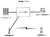
図1は、本発明に係る通信ネットワークの実施形態の一例を示すブロック図である。携帯電話システム01は、携帯電話機10と、携帯電話基地局11と、サービスセンター12と、電子メール受信用端末13と、ネットワーク網14とから構成されている。ネットワーク網14には、図示しない交換機システムを介して、携帯電話基地局11と、サービスセンター12と、電子メール受信用端末13とが通常、有線で接続されている。携帯電話機10と、携帯電話基地局11とは無線で音声やデータ通信をすることが可能である。電子メール受信用端末13は、パーソナルコンピュータであり、パーソナルコンピュータの他に、PDAや携帯電話機もこれらの端末の一種となる。なお、10は、携帯電話機に限られず、例えば、PDA等の携帯端末であってもよい。 FIG. 1 is a block diagram showing an example of an embodiment of a communication network according to the present invention. The cellular phone system 01 includes a
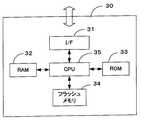
図2は、本発明の実施の形態となる携帯電話機の概略的なブロック図であり、図3は本発明の実施の形態となるSIMカードを示すブロック図である。 FIG. 2 is a schematic block diagram of a mobile phone according to an embodiment of the present invention, and FIG. 3 is a block diagram showing a SIM card according to an embodiment of the present invention.
携帯電話機10は、アンテナ15と、通信制御部16と、表示部17と、操作部18と、音声信号処理部19と、マイクロフォン20と、音量制御部21と、スピーカ22、バイブレータ23と、ライト24と、メモリ25と、各部を制御する制御部28と、カード装着部29と、SIM(Subscriber Information Module)カード30とを含む。携帯電話機10は、無線により携帯電話基地局11と通信が可能であり、さらに携帯電話基地局11は電話回線を含むネットワーク網14を介して電子メール受信用端末13及びサービスセンター12とも接続している。 The
アンテナ15によって受信された信号は、通信制御部16を介して制御部28に入力される。この信号には、通話信号、パケットデータに加え、リモートロック信号も含まれる。パケットデータには、テキストデータ、グラフィックスデータ、プログラムデータなどが含まれる。リモートロック信号は、ユーザが携帯電話機のサービスセンター12に携帯電話機10を紛失した旨の連絡・通知をした場合、該サービスセンター12より、予めユーザにより選択されたユーザデータを指定されたアドレスに送信し、携帯電話機10のメモリ25から選択された救済ユーザデータ、救済ユーザデータ選択情報及び送信先情報を削除し、携帯電話機10を再起動できなくするように遠隔操作で携帯電話機の動作をロックするものである。
なお、リモートロック信号は、サービスセンター12と携帯電話機10とで予め設定されている信号である。このため、モートロック信号がアンテナ15より制御部28に入力されるとき、制御部28は、予め設定されているリモートロック信号と、該リモートロック信号と異なる信号と、を識別する。A signal received by the
The remote lock signal is a signal set in advance by the service center 12 and the
制御部28は、表示する信号を表示部17に出力する。この表示部17は、入力される信号に基づいて文字・映像を表示するものである。表示部17としては、例えば、液晶パネルがある。 The
制御部28は、通信制御部16から入力される音声信号に基づいて、予め定められた処理を実行して音量制御部21に音声信号を出力する。音量制御部21は、入力される信号を予め定められた設定、あるいは操作部18を介して入力される設定に基づいて変換し、スピーカ22に出力する。ここで、操作部18は、テンキー等の入力キーを備え、ユーザからの指示を入力するためのものである。 The
携帯電話機10のユーザがマイクロフォン20に対して発した音声は、音声信号処理部19に入力される。音声信号処理部19は、予め定められた信号処理を実行して制御部28に出力する。この処理には、例えば音声信号の出力レベルの調整が含まれる。制御部28は、予め定められた変換処理を実行して通信制御部16に音声信号を出力する。通信制御部16は、制御部28からの信号に基づいて送信処理を実行する。この送信処理によって生成される信号は、アンテナ15を介して送信される。 The voice uttered by the user of the
制御部28は、通信制御部16から着信信号を受信すると、予め定められた設定に基づいて、バイブレータ23を振動させるための信号を出力する。バイブレータ23は、その信号に基づき振動し、携帯電話機10のユーザは、電話の着信等を知ることができる。 When receiving an incoming signal from the
ライト24は、制御部28から出力される信号に基づいて、予め設定された色の光を発する。ライト24は、制御部28から点滅の指令が出力された場合には、予め設定された間隔ごとに、点滅する。 The
メモリ25は、RAM26やROM27等から構成され、入力部の操作により入力又は電子メールにより受信等した、ユーザの個人的情報であるユーザデータを記憶する。また、メモリ25は、ユーザにより、ユーザの個人的情報であるユーザデータより選択された救済ユーザデータ、救済ユーザデータ選択情報及び送信先情報を記憶する。
なお、リモートロック信号のみならず、救済ユーザデータ選択情報及び送信先情報が外部よりアンテナ15によって受信されてもよい。かかる場合、リモートロック信号、救済ユーザデータ選択情報及び送信先情報は、通信制御部16を介し制御部28に入力される。そして、救済ユーザデータ選択情報及び送信先情報は、制御部28よりメモリ25に取り込まれて記憶される。The
In addition to the remote lock signal, the rescue user data selection information and the transmission destination information may be received from the outside by the
RAM26は、上記の各設定を記憶するための各種設定記憶領域、ライト24の発光条件その他の各種のデータを記憶するための各種データ記憶領域を含む。これらの領域に格納されるデータは、操作部18を介して入力される設定に基づいてユーザが任意に変更することができる。 The
ROM27は、予め作成された携帯電話機10の基本的な動作条件を制御するプログラム、あるいは初期データ等を記憶する。なお、ROM27に記憶されるデータは、RAM26に予め記憶されていてもよい。また、ROM27は、EPROM(Erasable and Programmable ROM)その他のデータの消去あるいは書き込みが可能なROMであってもよい。この場合、携帯電話機10の動作の制御に必要なデータあるいはソフトウェアを逐次更新することが可能になる。 The
このようにして、携帯電話機10における処理は、各ハードウェア、および制御部28あるいは通信制御部16により実行されるソフトウェアによって実現される。このようなソフトウェアは、メモリ25のRAM26あるいはROM27に予め記憶されている。
なお、制御部28は、メモリ25に記憶された救済ユーザデータ選択情報と送信先情報に基づいて、救済ユーザデータを、通信制御部16を介してアンテナ15から指定された送信先に送信するとともに、メモリ25から救済ユーザデータ、救済ユーザデータ選択情報及び送信先情報を消去して携帯電話機10を再起動できなくするように動作ロック処理を行う。In this way, the processing in the
The
SIMカード30は、携帯電話機側のカード装着部29に接続するインターフェース部31と、演算処理等のために一旦データを保持するためのRAM32と、OS(Operating System)を記憶するROM33と、加入者識別データや相手先電話番号等の通信情報を記憶するフラッシュメモリ34と、CPU35とを含む。 The
SIMカード30は、通話契約情報や個人情報を着脱自在の外部記憶装置に記憶するものである。SIMカード30には、IMSI(International Mobile Subscriber Identity)と呼ばれる固有の番号が付与されており、これと電話番号を結びつけることにより通信を可能とする。SIMカード30を抜き差しすることで、電話番号を他の携帯電話機に移したり、1つの携帯電話機で複数の電話番号を切替えて使用することができる。 The
SIMカード30のフラッシュメモリ34には、加入者契約情報を中心にデータが格納されている。ここで、加入者契約情報には、複数の電話番号、IMSI、識別暗証番号(PIN番号)、通話相手先電話番号等の情報が含まれている。また、各登録電話番号ごとに、相手先の電話番号を記憶でき、その相手先の電話番号にかけると、その登録電話番号の契約先に課金ができるようになっている。例えば、勤務会社が設定した登録電話番号に対応づけた相手先電話番号にかけると、会社に課金され、ユーザ個人用電話番号に対応づけた相手先電話番号にかけると、ユーザに課金される。さらに、相手先電話番号がSIMカード30に記憶されていない場合は、会社あるいはユーザのいずれに課金するかは、設定できるようになっているが、通常、SIMカード30に記憶されていない相手番号の場合はユーザ側に課金される。 The
以上が、通信ネットワークと携帯電話機の基本構成であるが、次に携帯電話機の実施形態について説明する。 The above is the basic configuration of the communication network and the mobile phone. Next, an embodiment of the mobile phone will be described.
<第1実施形態>
第1実施形態は、ユーザが保護すべき情報を既存のメール通信機能を利用して指定のアドレスに送信し、携帯電話機の機能のみでデータの回収を実現するとともに、保護すべきデータを消去するのみならず携帯電話機の再起動をさせなくするように動作ロックする制御処理である。<First Embodiment>
In the first embodiment, information to be protected is transmitted to a specified address using an existing mail communication function, data collection is realized only by the function of the mobile phone, and data to be protected is deleted. This is a control process for locking the operation so as not to restart the mobile phone.
図4は、本発明に係る携帯電話機の救済ユーザデータの設定を説明した図である。ユーザは、メモリ25に蓄積されているユーザデータ41から救済ユーザデータ42を選択する。選択できる救済ユーザデータ42の容量は決められている。決められた容量を超える救済ユーザデータ42を指定することはできない。この救済ユーザデータの制限に関しては、携帯電話機10、携帯電話基地局11、及びネットワーク網14に依存するものであり、適宜設定される。
なお、救済ユーザデータ、ユーザの個人的情報であるユーザデータのうち救済すべきユーザデータを選択した救済ユーザデータ選択情報、及びユーザにより選択される救済ユーザデータを送信する先の送信先情報は、メモリ25に蓄積される。FIG. 4 is a diagram for explaining the setting of the rescue user data of the mobile phone according to the present invention. The user selects the rescue user data 42 from the user data 41 stored in the
Relief user data, rescue user data selection information that selects user data to be rescued among user data that is personal information of the user, and transmission destination information to which rescue user data selected by the user is transmitted are: Accumulated in the
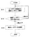
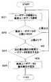
図5は、本発明に係る携帯電話機の救済ユーザデータの設定の流れをフローチャートで表したものである。ユーザがメモリ25に蓄積されているユーザデータより救済ユーザデータを選択する(S11)。制御部28は、選択された救済ユーザデータが携帯電話機10、携帯電話基地局11、及びネットワーク網14に依存して決められるデータ容量の上限を超えているか判断する(S12)。選択された救済ユーザデータが上記のデータ容量を超えていない場合には、制御部28により救済ユーザデータが設定される(S13)。また、選択された救済ユーザデータが上記のデータ容量を超えている場合には、ユーザが再度、携帯電話機10のユーザデータより救済ユーザデータを選択する。 FIG. 5 is a flowchart showing the flow of setting relief user data for the mobile phone according to the present invention. The user selects rescue user data from the user data stored in the memory 25 (S11). The
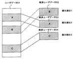
図6は、本発明の実施形態に係る携帯電話機のメモリ25に蓄積されているユーザデータと優先順位付救済ユーザデータとの関係を説明する図である。ユーザは、メモリ25に蓄積されているユーザデータから優先順位を定め、救済ユーザデータを選択する。優先順位の高い順から救済ユーザデータ52、救済ユーザデータ53、救済ユーザデータ54を表し、選択できる救済ユーザデータの容量は決められている。容量を超える救済ユーザデータ52〜54を指定することはできない。この救済ユーザデータの制限に関しては、携帯電話機10、携帯電話基地局11、及びネットワーク網14に依存するものであり、適宜設定される。
なお、救済ユーザデータ、ユーザの個人的情報であるユーザデータのうち優先順位を定め救済すべきユーザデータを選択した救済ユーザデータ選択情報、及びユーザにより選択された救済ユーザデータを送信する先の送信先情報は、メモリ25に蓄積される。FIG. 6 is a diagram for explaining the relationship between user data stored in the
Relief user data, rescue user data selection information for selecting user data to be rescued among user data that is personal information of the user, and transmission to which the rescue user data selected by the user is transmitted The previous information is stored in the
図7は、本発明に係る携帯電話機の救済ユーザデータを優先順位に基づき、複数設定する流れをフローチャートで表した図である。ユーザがメモリ25に蓄積されているユーザデータより救済ユーザデータを選択する(S21)。制御部28は、選択された救済ユーザデータが携帯電話機10、携帯電話基地局11、及びネットワーク網14に依存して決められるデータ容量の上限を超えているか判断する(S22)。前記データ容量の上限を超えている場合には、ユーザが再び、メモリ25に蓄積されているユーザデータより救済ユーザデータを選択する(S21)。選択された救済ユーザデータが上記のデータ容量を超えていない場合には、制御部28は、次の優先順位に選択する救済ユーザデータがあるかどうかを判断する(S23)。次の優先順位に選択する救済ユーザデータがある場合には、制御部28により、救済ユーザデータと優先順位が設定される(S24)。なお、次の優先順位に選択する救済ユーザデータがない場合には、ユーザが再び、メモリ25に蓄積されているユーザデータより救済ユーザデータを選択する(S21)。 FIG. 7 is a flowchart showing a flow of setting a plurality of rescue user data of the mobile phone according to the present invention based on the priority order. The user selects rescue user data from the user data stored in the memory 25 (S21). The
図8は、本発明に係る携帯電話機の救済ユーザデータの保護処理の一例をフローチャートにて説明した図である。 FIG. 8 is a flowchart illustrating an example of the protection user data protection process of the mobile phone according to the present invention.
ユーザは、携帯電話機10を紛失・放置した場合には、携帯電話機のサービスセンター12に携帯電話機10を紛失した旨の連絡・通知をする(S31)。そして、連絡・通知を受けたサービスセンター12より、リモートロック信号を送信し、携帯電話基地局11を介して携帯電話機10へ届けられる。(S32)。リモートロック信号は、アンテナ15により受信されて、通信制御部16を介して制御部28に取り込まれる。そして、制御部28は、メモリ25に記憶されている救済ユーザデータ選択情報と送信先情報に基づいて、メモリ25に記憶されている救済ユーザデータを、通信制御部16に取り込み、アンテナ15から指定された送信先に送信する(S33)。また、制御部28は、メモリ25から救済ユーザデータ、救済ユーザデータ選択情報及び送信先情報を消去する(S34)。さらに、制御部28は、携帯電話機10を再起動できなくするように動作ロック処理を行う(S35)。 When the user has lost or left the
図9は、本発明に係る携帯電話機の救済ユーザデータの保護処理の他例をフローチャートにて説明した図である。 FIG. 9 is a flowchart illustrating another example of the protection user data protection process of the mobile phone according to the present invention.
ユーザは、携帯電話機10を紛失・放置した場合には、携帯電話機のサービスセンター12に携帯電話機10を紛失した旨の連絡・通知をする(S41)。そして、連絡・通知を受けたサービスセンター12より、リモートロック信号を送信し、携帯電話基地局11を介して携帯電話機10へ届けられる。(S42)。リモートロック信号は、アンテナ15により受信されて、通信制御部16を介して制御部28に取り込まれる。そして、制御部28は、メモリ25に記憶されている救済ユーザデータ選択情報と送信先情報に基づいて、メモリ25の高優先順位に設定された救済ユーザデータを、通信制御部16に取り込み、アンテナ15から指定された送信先に送信する(S43)。また、制御部28は、予めユーザにより設定された優先順位に基づき、メモリ25から救済ユーザデータを消去し、併せてメモリ25から救済ユーザデータ選択情報及び送信先情報を消去する(S44)。さらに、制御部28は、携帯電話機10を再起動できなくするように動作ロック処理を行う(S45)。 When the user has lost or left the
<第2実施形態>
第2実施形態は、SIMカード30を接続することができる携帯電話機において、ユーザが保護すべき情報を既存のメール通信機能を利用して指定のアドレスに送信し、SIMカード30のPIN状態を完全ロック状態にして、メモリ26より保護すべきユーザデータを消去する制御処理である。<Second Embodiment>
In the second embodiment, in a mobile phone to which a
まず、本発明の実施形態に係る携帯電話機にSIMカード接続がある場合における通話処理について説明する。 First, call processing when the mobile phone according to the embodiment of the present invention has a SIM card connection will be described.
図10は、SIMカード30を装着することが可能である携帯電話機の場合、本発明に係る通信ネットワークの実施形態の他例を示すブロック図である。携帯通信会社がSIMカード30を発行する際に、加入者契約情報をSIMカード30に記憶させるとともに、加入者識別情報をサーバ36に登録しておく。なお、SIMカード30を装着可能である携帯電話機の場合、加入者識別番号をサーバに登録するところ、通信ネットワーク網にサーバ36が設けられる。サーバ36はSIMカード導入のとき設置されるものであり、本発明を実施するため新たな設備として設けられるものではない。 FIG. 10 is a block diagram showing another example of the embodiment of the communication network according to the present invention in the case of a mobile phone to which the
図11は、携帯電話機が発信する場合の手順を示すフローチャートである。ユーザが携帯電話機10の操作部18から電話番号を入力して発信を行う(S51)。携帯電話機10は、その発信地域の携帯電話基地局11とリンクを確立する(S52)。携帯電話機10は、SIMカード30のIMSIを携帯電話基地局11に送る。携帯電話基地局11は、このIMSIをネットワーク網15を介してサーバ36に送る。サーバ36は、加入者識別情報のIMSIに基づいて、予め登録されたSIMカード30であるかを識別して、その有効性を判定する(S53)。さらには、ユーザがPIN番号を入力することにより、サーバ36が記憶しているPIN番号(個人識別番号)と一致しているかを確認して、使用していているユーザが登録した個人であるかを確認する(S54)。 FIG. 11 is a flowchart showing a procedure when the mobile phone makes a call. The user makes a call by inputting a telephone number from the
SIMカード30とユーザが認証できると、通話可能となる。PIN番号が要求されているにも関わらす、ユーザが入力したPIN番号と、サーバ36が記憶しているPIN番号(個人識別番号)とが不一致であった場合には、SIMカード30のPIN状態が完全にロックされた状態、すなわち、PUKブロック状態になり、通話できずに処理は終了する。ここで、携帯電話機10の制御部28は、発信電話番号が、会社用電話番号に対応づけてSIMカード30に記憶した相手先電話番号か否かを確認する(S55)。そしてユーザは通話を行う(S56)。 If the
図12は、携帯電話機が受信する場合の手順を示すフローチャートである。
携帯電話機10は、携帯電話基地局11からアンテナ15と通信制御部16を介して制御部28に信号を受信した場合(S61)、着信電話番号がSIMカード30に登録されている電話番号かを確認する(S62)。登録電話番号であれば、スピーカ23、バイブレータ24、ライト25を使ってユーザに着信の報知を行う(S63)。そしてユーザは通話を行う(S64)。登録電話番号でなければ、処理を終了する。FIG. 12 is a flowchart showing a procedure when the mobile phone receives data.
When the
次に、本発明の実施形態に係る携帯電話機にSIM接続がある場合における救済ユーザデータの保護処理を説明する。図13は、本発明に係る携帯電話機がSIMカード30を装着できる場合における救済ユーザデータの保護の処理をフローチャートで表した図である。 Next, protection user data protection processing when the mobile phone according to the embodiment of the present invention has a SIM connection will be described. FIG. 13 is a flowchart showing the protection user data protection process when the mobile phone according to the present invention can be equipped with the
ユーザは、携帯電話機10を紛失・放置した場合には、サービスセンター12に携帯電話機10を紛失した旨の連絡・通知をする(S71)。そして、連絡・通知を受けたサービスセンター12は、リモートロック信号を送信し、携帯電話基地局11を介して携帯電話機10へ届けられる(S72)。リモートロック信号は、アンテナ15により受信されて、通信制御部16を介して制御部28に取り込まれる。リモートロック信号を受信した携帯電話機10でSIM接続のある場合、制御部28は、SIMカード30をPIN要求状態に変更する(S73)。次に、制御部28は、既存のメール通信機能を利用して、メモリ25に記憶されている救済ユーザデータ選択情報と送信先情報に基づいて、メモリ25に記憶されている救済ユーザデータを、通信制御部16に取り込み、アンテナ15から指定された送信先に送信する(S74)。なお、救済ユーザデータに優先順位が付けられている場合は、制御部28は、メモリ25に記憶されている救済ユーザデータ選択情報と送信先情報に基づいて、メモリ25の高優先順位に設定された救済ユーザデータを、通信制御部16に取り込み、アンテナ15から指定された送信先に送信し、救済ユーザデータがなくなるまで続ける(S74’)。そして、制御部28は、メモリ25から救済ユーザデータ、救済ユーザデータ選択情報及び送信先情報を消去する(S75)。なお、救済ユーザデータに優先順位が付けられている場合は、制御部28は、予めユーザにより設定された優先順位に基づき、メモリ25から救済ユーザデータを消去し、併せてメモリ25から救済ユーザデータ選択情報及び送信先情報を消去する(S75’)。その後、制御部28は、SIMカード30のPIN状態を完全ロック状態(PUKブロック状態)にしてサービスセンター12に対して依頼しない限り復旧できないようにする(S76)。その後、制御部28は、携帯電話機10を再起動できないように起動ロック処理を行う(S77)。 When the user has lost or left the
なお、制御部28は、携帯電話機10の電源をOFFにした後にSIMカード30を抜いて携帯電話機10の電源をONにしたときに、携帯電話機の起動シーケンスを書き換えて携帯電話機を使用できなくすることも可能である。 Note that the
本発明の実施形態では、救済するデータを予め設定するが、このときデータ容量の上限値で救済するデータを制限する機能を有するため、新たなデータ通信の仕組みを追加し、新たな設備投資をすることなく、既存のメール通信機能を利用して保護すべきデータを指定アドレスへ送信することが可能になる。また、最終的に必要ならば携帯電話機10を再起動できないように起動ロック処理を行うことができる。さらに、SIMカード30に接続できる携帯電話機の場合は、リモートロック信号受信時点でSIMカードをPIN要求状態にし、データ救済後にはSIMカード30のPIN状態を完全ロック状態(PUKブロック状態)にすることで、SIMカード30の不正使用を防ぐことが可能になる。 In the embodiment of the present invention, the data to be relieved is set in advance, but at this time, since it has a function of restricting the data to be relieved by the upper limit value of the data capacity, a new data communication mechanism is added and a new capital investment is made Without doing so, it becomes possible to transmit data to be protected to a specified address using an existing mail communication function. Further, if necessary, the activation lock process can be performed so that the
以上、添付図面を参照しながら本発明の好適な実施形態について説明したが、本発明は、上記の実施形態に限定されないことは言うまでもない。特に、本発明の実施形態においては、主に、携帯電話機について説明したが、携帯電話機に限られず、例えば、PDA等の携帯端末であってもよい。当業者であれば、特許請求の範囲に記載された範疇内において、各種の変更例または修正例に想到し得ることは明らかであり、それらについても当然に本発明の技術的範囲に属するものと了解される。 As mentioned above, although preferred embodiment of this invention was described referring an accompanying drawing, it cannot be overemphasized that this invention is not limited to said embodiment. In particular, in the embodiment of the present invention, a mobile phone has been mainly described. However, the present invention is not limited to a mobile phone, and may be a mobile terminal such as a PDA. It will be apparent to those skilled in the art that various changes and modifications can be made within the scope of the claims, and these are naturally within the technical scope of the present invention. Understood.
01 携帯電話システム
10 携帯電話機
11 携帯電話基地局
12 サービスセンター
13 電子メール受信用端末
14 ネットワーク網
15 アンテナ
16 通信制御部
17 表示部
18 操作部
19 音声信号処理部
20 マイクロフォン
21 音量制御部
22 スピーカ
23 バイブレータ
24 ライト
25 メモリ
26 RAM
27 ROM
28 制御部
29 カード装着部
30 SIMカード
31 インターフェース部
32 RAM
33 ROM
34 フラッシュメモリ
35 CPU
36 サーバ
41 ユーザデータ
42 救済ユーザデータ
51 ユーザデータ
52 救済ユーザデータ
53 救済ユーザデータ
54 救済ユーザデータ01
27 ROM
28
33 ROM
34
36 Server 41 User data 42 Relief user data 51
Claims (5)
Translated fromJapanese前記救済ユーザデータの送受信を行う送受信手段と、
携帯電話機の動作をロックさせるリモートロック信号を前記送受信手段が受信した場合、前記記憶手段に記憶されている救済ユーザデータ選択情報と送信先情報に基づいて、前記送受信手段から救済ユーザデータを指定された送信先に送信するとともに、前記記憶手段から救済ユーザデータ、救済ユーザデータ選択情報及び送信先情報を消去して動作ロックを行う制御手段と
を備えたことを特徴とする携帯端末。Storage means for storing user data which is personal information of the user, relief user data selection information for selecting user data to be rescued among the user data, and transmission destination information to which the relief user data is transmitted ,
Transmitting / receiving means for transmitting / receiving the rescue user data;
When the transmission / reception unit receives a remote lock signal for locking the operation of the mobile phone, the transmission / reception unit specifies relief user data based on the relief user data selection information and the transmission destination information stored in the storage unit. A portable terminal comprising: control means for transmitting to the transmission destination and erasing the relief user data, the relief user data selection information and the transmission destination information from the storage means and performing operation lock.
前記制御手段は、リモートロック信号を受信した場合、SIMカードのPIN状態をPIN要求状態に変更し、救済ユーザデータを指定された送信先に送信した後、SIMカードのPIN状態を完全ロック状態にすることを特徴とする請求項1乃至3のいずれかに記載の携帯端末。The storage means includes a removable SIM card,
When receiving the remote lock signal, the control means changes the PIN state of the SIM card to the PIN request state, transmits the rescue user data to the designated transmission destination, and sets the SIM card PIN state to the complete lock state. The mobile terminal according to claim 1, wherein the mobile terminal is a mobile terminal.
Priority Applications (1)
| Application Number | Priority Date | Filing Date | Title |
|---|---|---|---|
| JP2006289140AJP2008109306A (en) | 2006-10-24 | 2006-10-24 | Mobile device |
Applications Claiming Priority (1)
| Application Number | Priority Date | Filing Date | Title |
|---|---|---|---|
| JP2006289140AJP2008109306A (en) | 2006-10-24 | 2006-10-24 | Mobile device |
Publications (1)
| Publication Number | Publication Date |
|---|---|
| JP2008109306Atrue JP2008109306A (en) | 2008-05-08 |
Family
ID=39442319
Family Applications (1)
| Application Number | Title | Priority Date | Filing Date |
|---|---|---|---|
| JP2006289140APendingJP2008109306A (en) | 2006-10-24 | 2006-10-24 | Mobile device |
Country Status (1)
| Country | Link |
|---|---|
| JP (1) | JP2008109306A (en) |
Cited By (6)
| Publication number | Priority date | Publication date | Assignee | Title |
|---|---|---|---|---|
| JP2013503509A (en)* | 2009-08-28 | 2013-01-31 | ゼットティーイー コーポレイション | Smart card remote control method and system |
| US8718602B2 (en) | 2009-08-28 | 2014-05-06 | Zte Corporation | Method and system for remote control of smart card |
| JP2014086908A (en)* | 2012-10-24 | 2014-05-12 | Secom Co Ltd | Communication system, program, and communication method |
| US8744403B2 (en) | 2009-08-28 | 2014-06-03 | Zte Corporation | Method and system for remote control of a smart card |
| CN107948390A (en)* | 2017-11-27 | 2018-04-20 | 维沃移动通信有限公司 | The guard method of user data and mobile terminal |
| JP2023506062A (en)* | 2020-01-02 | 2023-02-14 | 維沃移動通信有限公司 | Methods for triggering discovery, terminal equipment and network equipment |
- 2006
- 2006-10-24JPJP2006289140Apatent/JP2008109306A/enactivePending
Cited By (10)
| Publication number | Priority date | Publication date | Assignee | Title |
|---|---|---|---|---|
| JP2013503509A (en)* | 2009-08-28 | 2013-01-31 | ゼットティーイー コーポレイション | Smart card remote control method and system |
| US8718602B2 (en) | 2009-08-28 | 2014-05-06 | Zte Corporation | Method and system for remote control of smart card |
| US8718603B2 (en) | 2009-08-28 | 2014-05-06 | Zte Corporation | Method and system for remote control of a smart card |
| US8744403B2 (en) | 2009-08-28 | 2014-06-03 | Zte Corporation | Method and system for remote control of a smart card |
| JP2014086908A (en)* | 2012-10-24 | 2014-05-12 | Secom Co Ltd | Communication system, program, and communication method |
| CN107948390A (en)* | 2017-11-27 | 2018-04-20 | 维沃移动通信有限公司 | The guard method of user data and mobile terminal |
| JP2023506062A (en)* | 2020-01-02 | 2023-02-14 | 維沃移動通信有限公司 | Methods for triggering discovery, terminal equipment and network equipment |
| JP7671758B2 (en) | 2020-01-02 | 2025-05-02 | 維沃移動通信有限公司 | How to trigger discovery; |
| JP7671758B6 (en) | 2020-01-02 | 2025-06-10 | 維沃移動通信有限公司 | Method for triggering discovery and terminal device - Patents.com |
| US12349072B2 (en) | 2020-01-02 | 2025-07-01 | Vivo Mobile Communication Co., Ltd. | Method for triggering terminal to start discovery process via network device, terminal device, and network device |
Similar Documents
| Publication | Publication Date | Title |
|---|---|---|
| JP5980496B2 (en) | Access point connection apparatus and method for portable terminal | |
| US8775801B2 (en) | Radio communication apparatus and radio communication method | |
| US8620217B2 (en) | Short range wireless communication apparatus | |
| JP2003199168A (en) | Telephone system capable of making call from external equipment | |
| JP2008109306A (en) | Mobile device | |
| JPWO2010082334A1 (en) | Communication device, communication system, and inter-device connection method | |
| JP3805990B2 (en) | Communication control method for portable terminal device | |
| EP1874069A1 (en) | Method for tracking a lost mobile station | |
| CN1072859C (en) | A cellular/pcs handset nam download capability using a wide-area page system | |
| KR101170150B1 (en) | Method for different typed network additional service processing of mobile terminal and the mobile terminal therefor | |
| KR20070122379A (en) | Lost mobile terminal tracking method | |
| JP2000078070A (en) | Memory backup mode and memory backup system for mobile communication equipment, mobile communication equipment and information transmitter/receiver | |
| CN103281415A (en) | Split mobile terminal and processing method for mobile terminal private data | |
| KR20060095316A (en) | Mobile terminal personal information management device and method | |
| KR20060071241A (en) | Short message filtering device and method, wireless communication terminal and method using same | |
| JP3219575B2 (en) | Mobile phone equipment | |
| KR100484438B1 (en) | Remote locking method in mobile telecommunication terminal | |
| JP2006211377A (en) | Wireless terminal device | |
| KR101063808B1 (en) | How to Display Text Message Information of Mobile Communication Terminal | |
| KR100645209B1 (en) | How to update shared secret data with mobile terminal | |
| WO2013180046A1 (en) | Portable terminal using ic card | |
| KR101106695B1 (en) | Method for managing a mobile terminal with a message | |
| JP2007006192A (en) | Communication terminal device | |
| KR100632104B1 (en) | Mobile communication terminal and automatic call disconnection system | |
| JP2005328346A (en) | Communication control method, communication system, program, and communication terminal |