JP2008104855A - Manipulator system - Google Patents
Manipulator systemDownload PDFInfo
- Publication number
- JP2008104855A JP2008104855AJP2007206850AJP2007206850AJP2008104855AJP 2008104855 AJP2008104855 AJP 2008104855AJP 2007206850 AJP2007206850 AJP 2007206850AJP 2007206850 AJP2007206850 AJP 2007206850AJP 2008104855 AJP2008104855 AJP 2008104855A
- Authority
- JP
- Japan
- Prior art keywords
- unit
- manipulator system
- working
- manipulator
- actuator
- Prior art date
- Legal status (The legal status is an assumption and is not a legal conclusion. Google has not performed a legal analysis and makes no representation as to the accuracy of the status listed.)
- Granted
Links
Images


Classifications
- A—HUMAN NECESSITIES
- A61—MEDICAL OR VETERINARY SCIENCE; HYGIENE
- A61B—DIAGNOSIS; SURGERY; IDENTIFICATION
- A61B90/00—Instruments, implements or accessories specially adapted for surgery or diagnosis and not covered by any of the groups A61B1/00 - A61B50/00, e.g. for luxation treatment or for protecting wound edges
- A61B90/90—Identification means for patients or instruments, e.g. tags
- A61B90/94—Identification means for patients or instruments, e.g. tags coded with symbols, e.g. text
- A61B90/96—Identification means for patients or instruments, e.g. tags coded with symbols, e.g. text using barcodes
- A—HUMAN NECESSITIES
- A61—MEDICAL OR VETERINARY SCIENCE; HYGIENE
- A61B—DIAGNOSIS; SURGERY; IDENTIFICATION
- A61B34/00—Computer-aided surgery; Manipulators or robots specially adapted for use in surgery
- A61B34/70—Manipulators specially adapted for use in surgery
- A—HUMAN NECESSITIES
- A61—MEDICAL OR VETERINARY SCIENCE; HYGIENE
- A61B—DIAGNOSIS; SURGERY; IDENTIFICATION
- A61B34/00—Computer-aided surgery; Manipulators or robots specially adapted for use in surgery
- A61B34/70—Manipulators specially adapted for use in surgery
- A61B34/71—Manipulators operated by drive cable mechanisms
- A—HUMAN NECESSITIES
- A61—MEDICAL OR VETERINARY SCIENCE; HYGIENE
- A61B—DIAGNOSIS; SURGERY; IDENTIFICATION
- A61B34/00—Computer-aided surgery; Manipulators or robots specially adapted for use in surgery
- A61B34/70—Manipulators specially adapted for use in surgery
- A61B34/72—Micromanipulators
- A—HUMAN NECESSITIES
- A61—MEDICAL OR VETERINARY SCIENCE; HYGIENE
- A61B—DIAGNOSIS; SURGERY; IDENTIFICATION
- A61B90/00—Instruments, implements or accessories specially adapted for surgery or diagnosis and not covered by any of the groups A61B1/00 - A61B50/00, e.g. for luxation treatment or for protecting wound edges
- A61B90/90—Identification means for patients or instruments, e.g. tags
- A61B90/98—Identification means for patients or instruments, e.g. tags using electromagnetic means, e.g. transponders
- A—HUMAN NECESSITIES
- A61—MEDICAL OR VETERINARY SCIENCE; HYGIENE
- A61B—DIAGNOSIS; SURGERY; IDENTIFICATION
- A61B17/00—Surgical instruments, devices or methods
- A61B2017/00367—Details of actuation of instruments, e.g. relations between pushing buttons, or the like, and activation of the tool, working tip, or the like
- A61B2017/00398—Details of actuation of instruments, e.g. relations between pushing buttons, or the like, and activation of the tool, working tip, or the like using powered actuators, e.g. stepper motors, solenoids
- A—HUMAN NECESSITIES
- A61—MEDICAL OR VETERINARY SCIENCE; HYGIENE
- A61B—DIAGNOSIS; SURGERY; IDENTIFICATION
- A61B17/00—Surgical instruments, devices or methods
- A61B2017/0046—Surgical instruments, devices or methods with a releasable handle; with handle and operating part separable
- A—HUMAN NECESSITIES
- A61—MEDICAL OR VETERINARY SCIENCE; HYGIENE
- A61B—DIAGNOSIS; SURGERY; IDENTIFICATION
- A61B17/00—Surgical instruments, devices or methods
- A61B2017/00477—Coupling
- A61B2017/00482—Coupling with a code
- A—HUMAN NECESSITIES
- A61—MEDICAL OR VETERINARY SCIENCE; HYGIENE
- A61B—DIAGNOSIS; SURGERY; IDENTIFICATION
- A61B90/00—Instruments, implements or accessories specially adapted for surgery or diagnosis and not covered by any of the groups A61B1/00 - A61B50/00, e.g. for luxation treatment or for protecting wound edges
- A61B90/08—Accessories or related features not otherwise provided for
- A61B2090/0803—Counting the number of times an instrument is used
- A—HUMAN NECESSITIES
- A61—MEDICAL OR VETERINARY SCIENCE; HYGIENE
- A61B—DIAGNOSIS; SURGERY; IDENTIFICATION
- A61B90/00—Instruments, implements or accessories specially adapted for surgery or diagnosis and not covered by any of the groups A61B1/00 - A61B50/00, e.g. for luxation treatment or for protecting wound edges
- A61B90/08—Accessories or related features not otherwise provided for
- A61B2090/0804—Counting number of instruments used; Instrument detectors
- A61B2090/0805—Counting number of instruments used; Instrument detectors automatically, e.g. by means of magnetic, optical or photoelectric detectors
- A—HUMAN NECESSITIES
- A61—MEDICAL OR VETERINARY SCIENCE; HYGIENE
- A61B—DIAGNOSIS; SURGERY; IDENTIFICATION
- A61B90/00—Instruments, implements or accessories specially adapted for surgery or diagnosis and not covered by any of the groups A61B1/00 - A61B50/00, e.g. for luxation treatment or for protecting wound edges
- A61B90/30—Devices for illuminating a surgical field, the devices having an interrelation with other surgical devices or with a surgical procedure
- A61B2090/309—Devices for illuminating a surgical field, the devices having an interrelation with other surgical devices or with a surgical procedure using white LEDs
- A—HUMAN NECESSITIES
- A61—MEDICAL OR VETERINARY SCIENCE; HYGIENE
- A61B—DIAGNOSIS; SURGERY; IDENTIFICATION
- A61B90/00—Instruments, implements or accessories specially adapted for surgery or diagnosis and not covered by any of the groups A61B1/00 - A61B50/00, e.g. for luxation treatment or for protecting wound edges
- A61B90/36—Image-producing devices or illumination devices not otherwise provided for
- A61B90/361—Image-producing devices, e.g. surgical cameras
- A—HUMAN NECESSITIES
- A61—MEDICAL OR VETERINARY SCIENCE; HYGIENE
- A61B—DIAGNOSIS; SURGERY; IDENTIFICATION
- A61B90/00—Instruments, implements or accessories specially adapted for surgery or diagnosis and not covered by any of the groups A61B1/00 - A61B50/00, e.g. for luxation treatment or for protecting wound edges
- A61B90/36—Image-producing devices or illumination devices not otherwise provided for
- A61B90/37—Surgical systems with images on a monitor during operation
Landscapes
- Health & Medical Sciences (AREA)
- Surgery (AREA)
- Life Sciences & Earth Sciences (AREA)
- Engineering & Computer Science (AREA)
- Animal Behavior & Ethology (AREA)
- General Health & Medical Sciences (AREA)
- Biomedical Technology (AREA)
- Heart & Thoracic Surgery (AREA)
- Medical Informatics (AREA)
- Molecular Biology (AREA)
- Nuclear Medicine, Radiotherapy & Molecular Imaging (AREA)
- Veterinary Medicine (AREA)
- Public Health (AREA)
- Robotics (AREA)
- Oral & Maxillofacial Surgery (AREA)
- Pathology (AREA)
- Physics & Mathematics (AREA)
- Electromagnetism (AREA)
- Manipulator (AREA)
- Eye Examination Apparatus (AREA)
Abstract
Translated fromJapaneseDescription
Translated fromJapanese本発明は、マニピュレータと該マニピュレータを制御するマニピュレータシステムに関し、特に、アクチュエータを有するアクチュエータ部と、該アクチュエータ部に対して着脱自在で、アクチュエータに連携して動作する動作部を備える作業部とからなるマニピュレータを有するマニピュレータシステムに関する。 The present invention relates to a manipulator and a manipulator system that controls the manipulator, and in particular, includes an actuator unit having an actuator, and a working unit that is detachable from the actuator unit and includes an operation unit that operates in conjunction with the actuator. The present invention relates to a manipulator system having a manipulator.
腹腔鏡下手術においては、患者の腹部等に小さな孔をいくつかあけて内視鏡、マニピュレータ(又は鉗子)等を挿入し、術者が内視鏡の映像をモニタで見ながら手術を行っている。このような腹腔鏡下手術は、開腹を必要としないため患者への負担が少なく、術後の回復や退院までの日数が大幅に低減されることから、適用分野の拡大が期待されている。 In laparoscopic surgery, a small hole is made in the patient's abdomen, etc., and an endoscope, manipulator (or forceps), etc. are inserted, and the surgeon performs the operation while viewing the endoscope image on the monitor. Yes. Since such laparoscopic surgery does not require laparotomy, the burden on the patient is small, and the number of days until postoperative recovery and discharge is greatly reduced, and therefore, the application field is expected to expand.
マニピュレータシステムは、例えば特許文献1に記載されているように、マニピュレータ本体と、該マニピュレータ本体を制御する制御装置とから構成される。マニピュレータ本体は、人手によって操作される操作部と、操作部に対して交換自在に着脱される作業部とから構成される。 For example, as described in
作業部は長い連結シャフトと、該連結シャフトの先端に設けられた先端動作部(エンドエフェクタとも呼ばれる。)とを有し、ワイヤによって先端の作業部を駆動するモータが操作部に設けられている。ワイヤは基端側でプーリに巻き掛けられている。制御装置は、操作部に設けられたモータを駆動して、プーリを介してワイヤを循環駆動する。 The working unit has a long connecting shaft and a tip operating unit (also referred to as an end effector) provided at the tip of the connecting shaft, and a motor for driving the tip working unit by a wire is provided in the operating unit. . The wire is wound around the pulley on the proximal end side. The control device drives a motor provided in the operation unit to circulate and drive the wire via the pulley.
作業部側は洗浄、滅菌を容易にする必要性からセンサなどの電子機器を含まず、先端動作部及び後端のプーリの位置又は原点を直接的には検出できない構成であり、モータの回転量に基づいて先端動作部の姿勢を算出する構成がとられている。 The working unit side does not include electronic devices such as sensors because of the need for easy cleaning and sterilization, and the position or origin of the front operating unit and the rear end pulley cannot be detected directly. The configuration for calculating the posture of the distal end working unit based on the above is adopted.
ところで、腹腔鏡下手術では、手技に応じて多様な作業部が用いられ、例えばグリッパ、はさみ、電気メス、超音波メス、医療用ドリルなどが挙げられる。これらの作業部は操作部に対して着脱自在に構成され、装着時には作業部基端側のプーリが操作部に設けられたモータの回転軸に係合するように構成されている。 By the way, in laparoscopic surgery, various working units are used depending on the procedure, and examples include a gripper, scissors, an electric knife, an ultrasonic knife, and a medical drill. These working units are configured to be detachable from the operation unit, and when installed, the pulley on the proximal side of the working unit is configured to engage with a rotation shaft of a motor provided in the operation unit.
このように、1つの操作部に対して複数の異なる作業部を接続することを前提としているシステムの場合、すべての作業部が唯一共通して着脱のできる姿勢となるモータ位相を設定する必要がある(例えば、特許文献1参照)。これを原点(又は初期位置)としている。 As described above, in the case of a system on the assumption that a plurality of different working units are connected to one operation unit, it is necessary to set a motor phase in which all the working units are in a common and attachable / detachable posture. Yes (see, for example, Patent Document 1). This is the origin (or initial position).
マニピュレータシステムについての先行技術としては、下記の特許文献1〜特許文献3が挙げられる。 As the prior art regarding the manipulator system, the following
特許文献1では、着脱時におけるモータ励磁切り換えや電気的な構成については考慮する必要のない構成が提案されている。
特許文献2では、複数の先端ツール(作業部)の電気的着脱について記載されている。
特許文献3は、医療用マニピュレータの着脱について、先端のマニピュレータにIDを取得するためのメモリを有していて制御装置がその情報を取得して制御することが記載されている。メモリはROM又はフラッシュメモリ等であり、電気的接点を介してIDが伝達される。
従来外科手術が行われる際には、外科医が患者の内部を直接見ながら手術が出来るように大きな切開が施された。大きな切開は、患者の回復遅らせたりするものであった。近年、多くの外科医は内視鏡下での低侵襲の外科手術を行い、切開を著しく小さくすることが出来ている。 Conventionally, when a surgical operation is performed, a large incision is made so that the surgeon can perform an operation while directly looking inside the patient. A large incision would delay patient recovery. In recent years, many surgeons have performed endoscopic minimally invasive surgery and have been able to significantly reduce the incision.
ロボット外科器具は低侵襲外科手術をさらに発展させてきている。それらの外科器具は高度に専門的になっている。それらの外科器具は外科医の最小化された動きに追随しなければならない。外科医は臓器に対して切断、剥離そして縫合等の多くの異なったことを行う。異なったそれぞれの外科器具はそれぞれの機能を要求される。それぞれの機能のために異なった医療器具が作られる。しかし、単にコントロールユニットに接続された外科器具を機能ごとに代える方が経済的である。外科器具のコントロールを正確に行うためには、取り付けられるそれぞれの外科器具を認識しなければならない。 Robotic surgical instruments have further developed minimally invasive surgical procedures. Those surgical instruments are highly specialized. These surgical instruments must follow the surgeon's minimized movement. The surgeon does many different things to the organ, such as cutting, peeling and suturing. Different surgical instruments are required for their respective functions. Different medical devices are made for each function. However, it is more economical to simply replace the surgical instrument connected to the control unit for each function. In order to accurately control the surgical instrument, each attached surgical instrument must be recognized.
つまり、アクチュエータ部に対して種々の作業部が装着可能である場合、制御部では作業部の種類に応じた制御を行う必要があり、作業部の個体情報が必要となる。 That is, when various working units can be attached to the actuator unit, the control unit needs to perform control according to the type of the working unit, and individual information of the working unit is required.
また、上記のとおり先端動作部の姿勢は、例えば原点位置を基準として算出されることから、手術の途中で作業部を交換する場合には、次の作業に備えて該作業部は正確に原点に一致した軸位置としてから取り外すことが望ましい。原点位置に一致していない状態で取り外されたときには、所定の警報を発してその作業部を再装着するように促すとよいが、このとき別の作業部を装着されることがないように作業部を識別することが必要になる。 Further, as described above, the posture of the distal end working unit is calculated with reference to the origin position, for example. Therefore, when replacing the working unit during surgery, the working unit is accurately set to the origin in preparation for the next operation. It is desirable to remove the shaft after matching the shaft position. If it is removed in a state that does not match the origin position, it is recommended to issue a predetermined alarm and prompt the user to reattach the working part. It is necessary to identify the part.
前記の特許文献3ではROMからツールの個体情報を読取ることができ、該個体情報に応じて作業部の種類に応じた制御が可能となる。しかしながら、前記の通り、作業部は一連の手術が終了した後に洗浄及び滅菌を行う必要から電子機器を含まないことが望まれ、特に電気的接点がないことが望ましい。 In
また、取得した個体情報に基づいて作業部ごとの使用の経緯が分かると作業部の管理が容易となり好適である。しかしながら、接続される制御部は複数台用意されている場合もあり、所定の制御部に作業部の使用履歴を保存しておくと、該作業部を他の制御部に接続しても使用の経緯が分からず、不便である。 In addition, it is preferable to know the history of use for each work unit based on the acquired individual information, so that the work unit can be easily managed. However, there may be a plurality of connected control units, and if the usage history of a work unit is stored in a predetermined control unit, it can be used even if the work unit is connected to another control unit. I don't know the background and it's inconvenient.
本発明はこのような課題を考慮してなされたものであり、作業部の個体情報を取得することができ、しかも該作業部を簡便に洗浄及び滅菌することのできるマニピュレータシステムを提供することを目的とする。 The present invention has been made in consideration of such problems, and provides a manipulator system that can acquire individual information of a working unit and that can easily clean and sterilize the working unit. Objective.
本発明に係るマニピュレータシステムは、マニピュレータ及び該マニピュレータを制御する制御部とを備えるマニピュレータシステムにおいて、前記マニピュレータは、アクチュエータが備えられたアクチュエータ部と、前記アクチュエータ部に対して着脱自在で、シャフトの先端に前記アクチュエータに連動して前記シャフト軸と非平行な軸を基準として回動する先端動作部を備える作業部とを有し、前記作業部は、固体識別用の個体信号を保持するID保持部を備え、前記アクチュエータ部は、前記ID保持部に対して非接触で、該ID保持部の前記個体信号を認識し前記制御部へ供給するID認識部を備え、前記制御部は、供給された前記個体信号に基づいて前記作業部の制御をすることを特徴とする。 The manipulator system according to the present invention is a manipulator system including a manipulator and a control unit for controlling the manipulator, wherein the manipulator is detachable from the actuator unit provided with an actuator and the tip of the shaft. And an operation unit including a tip operation unit that rotates with respect to an axis that is not parallel to the shaft axis in conjunction with the actuator, and the operation unit holds an individual signal for identifying a solid. The actuator unit includes an ID recognition unit that is in non-contact with the ID holding unit, recognizes the individual signal of the ID holding unit, and supplies the signal to the control unit, and the control unit is supplied The working unit is controlled based on the individual signal.
このように、非接触のID保持部及びID認識部を用いることにより、作業部の個体情報を取得することができるとともに、電気的接点がなく、作業部を簡便に洗浄及び滅菌することができる。また、電気的接点がないことから、該接点の不良による通信エラーがない。一般に、非接触手段は電気的接点よりも高寿命である。 As described above, by using the non-contact ID holding unit and the ID recognition unit, the individual information of the working unit can be acquired, and there is no electrical contact, and the working unit can be easily cleaned and sterilized. . Further, since there is no electrical contact, there is no communication error due to the failure of the contact. In general, non-contact means have a longer life than electrical contacts.
本発明では、ロボットコントロールが正しく信頼性が高く外科器具をコントロール出来るようにロボット外科装置にマウントされる外科器具の認識を行う装置と方法が提供される。具体的には、装置は外科器具と外科器具コントロールメカニズムを含むがこれに限定されない。外科器具は外科器具を認識するトランスミッターと外科器具を含むがこれに限定されない。外科器具コントロール機構は送られるID情報を受けとるレシーバを持つ。ただし、これには限定されない。 The present invention provides an apparatus and method for recognizing a surgical instrument mounted on a robotic surgical apparatus so that robotic control is correct and reliable and can control the surgical instrument. Specifically, the device includes, but is not limited to, a surgical instrument and a surgical instrument control mechanism. Surgical instruments include, but are not limited to, transmitters that recognize surgical instruments and surgical instruments. The surgical instrument control mechanism has a receiver that receives the transmitted ID information. However, it is not limited to this.
他の具体例は、外科装置は外科器具と外科器具コントロールメカニズムを持つ。しかしこれに限定されない。外科器具は外科器具と外科器具を特定する認識部を含む。しかしこれには限定されない。外科器具コントロールメカニズムは認識部を読み取る読み取り装置を含む。ただし、これに限定されない。 In another embodiment, the surgical device has a surgical instrument and a surgical instrument control mechanism. However, it is not limited to this. The surgical instrument includes a surgical instrument and a recognition unit that identifies the surgical instrument. However, it is not limited to this. The surgical instrument control mechanism includes a reader that reads the recognizer. However, it is not limited to this.
別の具体例は低侵襲手術に使用される外科器具を自動的に認識する方法を提供する。その方法は、個別情報をレシーバで受け取り、その情報に基づいて外科器具をコントロールする方法を含む。ただし、これに限定はされない。外科器具が装置にマウントされた状態で認識が行われる。 Another embodiment provides a method for automatically recognizing surgical instruments used in minimally invasive surgery. The method includes receiving individual information at a receiver and controlling a surgical instrument based on the information. However, it is not limited to this. Recognition is performed with the surgical instrument mounted on the device.
別の具体例は低侵襲手術に使用される外科器具を自動的に認識する方法を提供する。その方法は、個別情報をレシーバで読み取り、その情報に基づいて外科器具をコントロールする方法を含む。ただし、これに限定はされない。外科器具が装置に取り付けられた状態で認識が行われる。 Another embodiment provides a method for automatically recognizing surgical instruments used in minimally invasive surgery. The method includes a method of reading individual information with a receiver and controlling a surgical instrument based on the information. However, it is not limited to this. Recognition is performed with the surgical instrument attached to the device.
本発明に係るマニピュレータシステムによれば、非接触のID保持部及びID認識部を用いることにより、作業部の個体情報を取得することができるとともに、電気的接点がないことから、作業部を簡便に洗浄及び滅菌することができる。 According to the manipulator system according to the present invention, by using the non-contact ID holding unit and the ID recognition unit, it is possible to acquire the individual information of the working unit, and since there is no electrical contact, the working unit is simplified. Can be washed and sterilized.
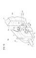
以下、本発明に係る実施形態として医療用のマニピュレータシステム500について添付の図1〜図20を参照しながら説明する。マニピュレータシステム500(図1参照)は、腹腔鏡下手術等に用いられるものである。 Hereinafter, a
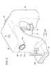
図1に示すように、マニピュレータシステム500は、マニピュレータ10と、コントローラ514とを有する。 As shown in FIG. 1, the
マニピュレータ10とコントローラ514との接続部には着脱可能なようにコネクタ520が設けられている。 A
マニピュレータ10は、先端動作部12に生体の一部又は湾曲針等を把持して所定の処置を行うためのものである。マニピュレータ10は、基本構成として操作部14と作業部16とからなる。コントローラ514は、マニピュレータ10の電気的な制御をするものであり、グリップハンドル26の下端部から延在するケーブル61に対してコネクタ520を介して接続されている。 The
コントローラ514は、マニピュレータ10を独立的に3台同時に制御することができる。コントローラ514のうち、第1、第2及び第3のマニピュレータ10を制御する部分を総括的に第1ポート515a、第2ポート515b及び第3ポート515cとも呼ぶ。図1及び図2に示すホストコンピュータ602については後述する。 The
図2に示すように、マニピュレータシステム500は、選択的に種々の構成を採りうる。すなわち、操作部14は、バリエーションとして操作部14a〜14dが用意され、作業部16は、バリエーションとして作業部16a〜16dが用意されている。 As shown in FIG. 2, the
コントローラ514には、操作部14aに代えて操作部14b、14c及び14dを装着することができる。また、各操作部14a〜14dに対し、作業部16aに代えて作業部16b、16c及び16dを装着することができる。すなわち、術者は手技の種類や慣れ等に応じて操作部14a〜14d及び作業部16a〜16dを選択的に組み合わせて構成することができる。このうち、作業部16bは先端動作部12がはさみとなっている。作業部16cは先端動作部12がブレード型電気メスとなっている。作業部16dは先端動作部12がフック型電気メスとなっている。各作業部16a〜16dは、接続部15内のプーリ50a、50b及び50c(図1参照)は共通の構成となっている。 The
前記のとおり、コントローラ514は、3台のマニピュレータ10を同時に制御可能であることから、操作部14a〜14dのうちいずれか3つを第1ポート515a、第2ポート515b及び第3ポート515cに接続が可能である。 As described above, since the
次に、操作部14及び作業部16からなるマニピュレータ10について説明する。 Next, the
マニピュレータ10は、先端動作部12に生体の一部又は湾曲針等を把持して所定の処置を行うためのものであり、通常、把持鉗子やニードルドライバ(持針器)等とも呼ばれる。 The
図1及び図3に示すように、マニピュレータ10は、人手によって把持及び操作される操作部14と、該操作部14に対して着脱自在な作業部16とを有する。 As shown in FIGS. 1 and 3, the
以下の説明では、図1における幅方向をX方向、高さ方向をY方向及び、連結シャフト48の延在方向をZ方向と規定する。また、右方をX1方向、左方をX2方向、上方向をY1方向、下方向をY2方向、前方をZ1方向、後方をZ2方向と規定する。さらに、特に断りのない限り、これらの方向の記載はマニピュレータ10が中立姿勢である場合を基準として表すものとする。これらの方向は説明の便宜上のものであり、マニピュレータ10は任意の向きで(例えば、上下を反転させて)使用可能であることはもちろんである。 In the following description, the width direction in FIG. 1 is defined as the X direction, the height direction is defined as the Y direction, and the extending direction of the connecting
作業部16は、作業を行う先端動作部12と、操作部14のアクチュエータブロック(アクチュエータ部)30に対して接続される接続部15と、これらの先端動作部12と接続部15とを連接する長尺で中空の連結シャフト48とを有する。作業部16はアクチュエータブロック30における所定の操作によって操作部14から離脱可能であって、洗浄、滅菌及びメンテナンス等を行うことができる。ここで、アクチュエータブロック30は作業部16が装着される箇所を意味するものであり、モータ40、41、42を格納する場所に限定されず、ブリッジ28との接続面30aを含む。 The working
先端動作部12及び連結シャフト48は細径に構成されており、患者の腹部等に設けられた円筒形状のトラカール20から体腔22内に挿入可能であり、操作部14の操作により体腔22内において患部切除、把持、縫合及び結紮等の様々な手技を行うことができる。 The distal
操作部14は、人手によって把持されるグリップハンドル26と、該グリップハンドル26の上部から延在するブリッジ28と、該ブリッジ28の先端に接続されたアクチュエータブロック30とを有する。 The
図1に示すように、操作部14のグリップハンドル26は、ブリッジ28の端部からY2方向に向かって延在しており、人手によって把持されるのに適した長さであり、入力手段としてのトリガーレバー32と、複合入力部34と、スイッチ36とを有する。 As shown in FIG. 1, the grip handle 26 of the
ブリッジ28の上面(又は側面)における視認しやすい箇所にはLED(インジケータ)29が設けられている。LED29は、マニピュレータ10の制御状態を示すインジケータであり、操作者が容易に認識可能な大きさであり、かつ操作に支障がない程度に十分に小型軽量である。LED29は、ブリッジ28の上面における略中央部で、視認性のよい位置に設けられている。 An LED (indicator) 29 is provided at an easily visible position on the upper surface (or side surface) of the
グリップハンドル26の下端には、コントローラ514に接続されるケーブル61が設けられている。グリップハンドル26とケーブル61とは一体的に接続されている。グリップハンドル26とケーブル61とはコネクタにより接続されていてもよい。 A
複合入力部34は、先端動作部12に対してロール方向(軸回転方向)及びヨー方向(左右方向)の回転指令を与える複合的な入力手段であり、例えば軸回転に動作する第1入力手段によってロール方向指示を行い、横方向に動作する第2入力手段によってヨー方向指示を行うことができる。トリガーレバー32は、先端動作部12のグリッパ59(図1参照)の開閉指令を与える入力手段である。スイッチ36は、マニピュレータ10の動作状態の有効又は無効を設定するための入力手段である。 The
図3及び図4に示すように、複合入力部34、トリガーレバー32には、それぞれ動作量を検出する入力センサ39a、39b、39cが設けられており、検出した動作信号(例えばアナログ信号)をコントローラ514に供給する。 As shown in FIGS. 3 and 4, the
トリガーレバー32は、ブリッジ28のやや下方でZ1方向にやや突出したレバーであり、人差し指による操作が容易な位置に設けられている。 The
トリガーレバー32は、グリップハンドル26に対してアーム98により接続されており、該グリップハンドル26に対して進退するように構成されている。 The
スイッチ36はグリップハンドル26に対して進退する操作機構であって、トリガーレバー32とスイッチ36とはグリップハンドル26におけるZ1方向の面で、グリップハンドル26の長尺方向(Y方向)に並んで配置されている。スイッチ36はトリガーレバー32の直下(Y2方向)に設けられている。スイッチ36とトリガーレバー32との間には薄い板材130が設けられている。 The
スイッチ36はオルタネート式であって、一度手前(Z2方向)に引き込むことによってオン状態にロックされ、操作子36aは手前側の位置に保持される。再度スイッチ36を手前側に引き込むことによってオン状態は解除されてオフ状態となり、図示しない弾性体によって先端側(Z1方向)の位置に復帰する。このような操作により、スイッチ36は、オン状態又はオフ状態のいずれかに保持され、スイッチ36を押し続ける必要がない。従って、オン状態とオフ状態との切り換え時だけスイッチ36の操作をすればよく、それ以外のときはトリガーレバー32の操作をすることができ、スイッチ36とトリガーレバー32とを併存させるのに好適である。 The
また、スイッチ36はオン状態とオフ状態では操作子36aの突き出し量が異なる構成であることから、操作子36aを目視し又は触れることによって状態を確認することができる。 Further, since the
スイッチ36は、モードの変更をさせるものである。モードの状態はLED29及びコントローラ514の所定のランプの点灯状態によっても示される。具体的には、LED29及び所定のランプは、動作モードのときには緑色点灯、停止モードのときには消灯となる。また、自動原点復帰動作時及びリセット動作時には緑の点滅となり、アラーム発生時には赤の点滅となる。 The
これらのモード及び動作はスイッチ36の操作によって変更される。つまり、コントローラ514は、スイッチ36の状態を読み込み、オン状態であるときに動作モードとし、オン状態からオフ状態に切り換わったときに自動原点復帰動作としてモータ40、41、42を所定の原点に戻し、原点に戻った後に停止モードとする。 These modes and operations are changed by operating the
動作モードとは、操作部14の操作指令を有効にしてモータ40、41、42を駆動するモードである。停止モードは、操作部14の操作指令の有無に関わらずモータ40、41、42を停止させるモードである。また、リセット動作とは、所定の操作がなされたときにモータ40、41、42を自動的に所定の原点に戻す動作である。自動原点復帰動作及びリセット動作は、操作指令の有無に関わらずモータ40、41、42を動作させることから、自動モードとして分類される。 The operation mode is a mode in which the operation command of the
これらのモード及び動作はコントローラ514によって区別されて制御され、LED29及び所定のランプの点灯状態が切り換えられる。 These modes and operations are distinguished and controlled by the
アクチュエータブロック30には先端動作部12が有する3自由度の機構に対応してモータ40、モータ41及びモータ42が連結シャフト48の延在方向に沿って並列して設けられている。これらのモータ40、41及び42は小型、細径であって、アクチュエータブロック30はコンパクトな扁平形状に構成されている。アクチュエータブロック30は、操作部14のZ1方向端部の下方に設けられている。また、モータ40、41及び42は、操作部14の操作に基づき、コントローラ514の作用下に回転をする。 The
モータ40、41及び42には、回転角度を検出することのできる角度センサ43、44及び45が設けられており、検出した角度信号はコントローラ514に供給される。角度センサ43、44及び45としては、例えばロータリエンコーダが用いられる。 The
作業部16は、アクチュエータブロック30に対して接続される接続部15と、該接続部15からZ1方向に向かって延在する中空の連結シャフト48とを有する。接続部15には、モータ40、41及び42の駆動軸に接続されるプーリ50a、プーリ50b及びプーリ50cが回転自在に設けられている。プーリ50a〜50cにはそれぞれカップリングが設けられている。 The working
プーリ50a、プーリ50b及びプーリ50cには、ワイヤ52、ワイヤ53及びワイヤ54が巻き掛けられており、連結シャフト48の中空部分48a(図7参照)を通って先端動作部12まで延在している。ワイヤ52、ワイヤ53及びワイヤ54はそれぞれ同種、同径のものを用いることができる。 A
作業部16の接続部15は、アクチュエータブロック30における所定の操作によって操作部14から離脱可能であって、洗浄、滅菌及びメンテナンス等を行うことができる。また、作業部16は他の形式のものに交換可能であって、手技に応じて連結シャフト48の長さの異なるもの、又は先端動作部12の機構が異なるものを装着することができる。 The
接続部15は、プーリ50a、50b及び50cの中心穴に対して、モータ40、41及び42の回転軸40a、41a及び42aが嵌合するように構成されている。プーリ50a、50b及び50cのY2方向下端にはそれぞれ十字状の結合凸部が設けられ、回転軸40a、41a及び42aには十字状の結合凹部が設けられている。結合凸部と結合凹部は互いに係合可能に形成されており、モータ40、41及び42の回転がプーリ50a、50b及び50cに対して確実に伝達される。また、結合凸部と結合凹部とは原点位置以外で係合しないよう構成されている。また、これらの係合部は十字形状に限られない。 The connecting
アクチュエータブロック30におけるブリッジ28との接続面30aには、カメラ(ID認識部、撮像手段)106と、2つの白色LED(投光手段)105とが設けられている。接続面30aは、作業部16の接続部15におけるカバー37の端面に当接する面であり、XY平面を構成する。カメラ106は、後述するバーコード104(図5参照)を撮像するカメラであり、例えばCCD形式又はCMOS形式である。白色LED105は、光軸がバーコード104を照明する向きに設定されており、カメラ106はバーコード104を一層確実に認識することができる。白色LED105は、カメラ106を挟んで左右対称位置に設けられており、バーコード104をバランスよく照明することができる。白色LED105は、カメラ106を挟んで上下に設けられていてもよく、等間隔に3以上設けられていてもよい。白色LED105が十分な光量を有する場合には1つでもよい。 A camera (ID recognition unit, image pickup means) 106 and two white LEDs (light projection means) 105 are provided on the
接続部15が載置されるアクチュエータブロック30の上面30bにおいて、Z2方向の端部近傍には、接続部15の有無を検出する作業部検出手段107が設けられている。作業部検出手段107は、対向する位置に設けられた投光器107aと受光器107bとからなり、該投光器107aと該受光器107bとの間に接続部15の後端部の被検出片109が挿入されて遮光することにより該接続部15が装着されたことを検出できる。投光器107aと受光器107bは、X方向に対向する向きで且つ近接した位置に設けられている。投光器107aは例えばLEDであり、受光器107bは例えばフォトダイオードである。 On the
図5に示すように、接続部15におけるプーリ格納体300の上面でZ2方向端部近傍には二次元状のバーコード(ID保持部)104が設けられている。バーコード104は、例えば略正方形のマトリックス形状であり、桝目に従って白及び黒が印刷されている。バーコード104は、XY平面を構成する板104aに貼り付けられており、カバー37の後端部から適度な距離Pだけ前方(Z1方向)にずれた位置に設けられている。 As shown in FIG. 5, a two-dimensional bar code (ID holding unit) 104 is provided in the vicinity of the end portion in the Z2 direction on the upper surface of the
バーコード104には、作業部16の個体情報、仕様、タイムスタンプ(製造日等)やシリアルナンバー、使用回数上限等の情報が含まれている。バーコード104の保持する個体情報は、作業部毎に識別が可能なように異なる値が付与されている。 The
バーコード104は1枚に限らず、複数枚からなる構成であってもよい。バーコード104が2枚からなる場合、一枚は個体情報、製造日、シリアルナンバー等の個体特有の情報を示し、もう一枚は仕様、使用回数上限等の型式毎に共通的な情報を示すようにしてもよい。 The
バーコード104は二次元データに限らず、一次元形状であってもよい。バーコード104における枡目の色は白及び黒に限らず、赤外線吸収色及び赤外線反射色であってもよく、又は3色以上の色の区別により情報を示すようにしてもよい。 The
バーコード104に含まれる情報は、コントローラ514で読み込み動作状態表示部530(図1参照)に表示させ、又は所定の判断を行って注意又は警告を発させるとよい。 The information included in the
プーリ格納体300の後端面における下端には、小さい被検出片109が後方に向かって突出している。接続部15がアクチュエータブロック30に装着されると、被検出片109が投光器107aと受光器107bとの間に挿入されて受光器107bに対する投光器107aの光を遮光するとともに、バーコード104とカメラ106とはカメラ106の焦点距離Pだけ離れて対向する。 At the lower end of the rear end surface of the
このとき、カバー37は、バーコード104及びカメラ106が略閉空間内となるようにこれらの箇所を覆う。これにより、バーコード104及びカメラ106の汚れを防止することができるとともに、外乱光を遮蔽して安定した撮像が可能となる。また、閉空間となっても、白色LED105によりバーコード104が照明されることから、安定した撮像が可能である。バーコード104及びカメラ106を覆うカバー37は、アクチュエータブロック30に設けられていてもよい。バーコード104とカメラ106との相対的な位置及び向きが固定的であることから、カメラ106側では、バーコード104の位置及び向きを特定する必要がなく、これらを特定するためのコードが不要か又は少量で足り、その分、バーコード104における記録可能な情報量が多くなる。 At this time, the
作業部検出手段107によれば、コントローラ514において作業部16がアクチュエータブロック30に装着されているか否かを認識することができる。コントローラ514は作業部16がアクチュエータブロック30に装着されたとき(ここで、作業部16がアクチュエータ部30に装着されたときとは、厳密な意味ではなく、例えば、作業部16がアクチュエータ部30に装着された瞬間から、実質的な作業が開始されるまでの期間を含む意味である。)にカメラ106及び白色LED105を制御してバーコード104から個体信号を取得する。このように、コントローラ514では、少なくとも作業部16がアクチュエータブロック30に装着されたときに個体信号を取得すれば足り、それ以外のときにはカメラ106及び白色LED105の動作を停止しておくことができ、処理負荷が低減するとともに省電力化を図ることができる。 According to the work part detection means 107, the
カメラ106による撮像は、可視光に限らず、例えば赤外光を用いてもよい。赤外光を用いることにより、暗い場所でもバーコード104を明りょうに撮像することができる。赤外光を用いる場合には所定の赤外線LEDでバーコード104を照射してもよい。 Imaging by the
作業部検出手段107は、投光器107a及び受光器107bからなる構成に限らず、例えば被検出片109により操作されるリミットスイッチであってもよい。また、コントローラ514では、作業部16の個体情報を取得し、該個体情報に応じて作業部16の種類に応じた制御が可能となる。 The working
ところで、バーコード104は直接的な通電の必要がなく接続部15及び作業部16には電気的接点が存在せず、しかもバッテリ等の蓄電体もない。したがって、操作部14から取り外した作業部16は洗浄、滅菌等を容易に行うことができる。つまり、モータやスイッチ、センサなどの電気機器をすべて操作部14側に配し、連結シャフト48及び先端動作部12からなる機械構成部品のみからなるものを作業部16側に配することで洗浄性を向上させている。作業部16と操作部14では汚れ具合、汚れ種類、洗浄方法が異なり、異なるメンテナンスが行われるため、離脱して洗浄することが好適である。 By the way, the
接続部15を操作部14から取り外す場合には、アクチュエータブロック30の両側面に設けられたレバー206を押してそれぞれ外方に開くように傾動させ、該レバー206の楔部206aを、接続部15の両側面に設けられた係合片200から解放する。これにより接続部15を操作部14から上方(Y1方向)に引き抜き、取り外しが可能となる。アクチュエータブロック30の上面には3本のアライメントピン212が設けられており、接続部15に設けられた嵌合孔202に嵌合することにより該接続部15を安定して保持可能である。接続部15を操作部14に取り付ける場合には、3本のアライメントピン212がそれぞれ嵌合孔202に嵌合するように合わせて、接続部15を下方(Y2方向)に押し下げる。これにより、レバー206は一旦外方に拡がり、その後原位置に戻ることにより係合片200に係合して、接続が完了する。 When removing the
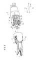
図7及び図8に示すように、先端動作部12はY方向の第1回転軸Oyを中心にして、それよりも先の部分がヨー方向に回動する第1自由度の機構(傾動機構、ピボット軸)と、第2回転軸Orを中心にしてロール方向に回動する第2自由度の機構(ロール回転機構)と、第3回転軸Ogを中心として先端のグリッパ59を開閉させる第3自由度とを有する合計3自由度の機構となっている。 As shown in FIGS. 7 and 8, the distal
第1自由度の機構である第1回転軸Oyは、連結シャフト48の基端側から先端側に延在する軸線Cと非平行に回動可能に設定するとよい。第2自由度の機構である第2回転軸Orは先端動作部12における先端部(つまりグリッパ59)の延在方向の軸線を中心として回動可能な機構とし、先端部をロール回転可能に設定するとよい。 The first rotation axis Oy, which is a mechanism having a first degree of freedom, may be set so as to be rotatable in a non-parallel manner with the axis C extending from the proximal end side to the distal end side of the connecting
先端動作部12は、ワイヤ52、ワイヤ53及びワイヤ54によって駆動され、各ワイヤ52、53及び54は、それぞれ対応する筒体60c、60b、60aに巻き掛けられている。 The distal
先端動作部12では、ワイヤ52及び54の作用下に歯車51及び55が回転し、図示しないフェイスギアを回転させることによって先端部をロール方向に回転させることができる。また、ワイヤ54の作用下に歯車51が回転し、フェイスギア57及び歯車58を介してグリッパ59を開閉させることができる。さらに、ワイヤ52、53、54の作用下に主軸部材62を介して先端部をヨー方向に回転させることができる。 In the distal
次に、コントローラ514について図9及び図10を参照しながら説明する。 Next, the
図9に示すように、コントローラ514の正面には、動作状態表示部530、電源情報表示部532、アラーム部534、アクティベートリセット部536、第1ポート515a、第2ポート515b、及び第3ポート515cが設けられている。 As shown in FIG. 9, on the front of the
動作状態表示部530は、術者や手術に携わる助手などが操作状態の確認が容易となるようにマニピュレータ10の動作状態や所定の対応指示を表示する液晶表示画面を有する。 The operation
第1ポート515a、第2ポート515b及び第3ポート515cは、それぞれのレセプタクルコネクタ572にマニピュレータ10が接続可能なポートであり、個別の情報表示部やリセットスイッチ570が設けられている。 The
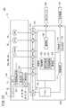
次に、コントローラ514の内部構成について図10を参照しながら説明する。なお、図10においては、煩雑とならないように第1ポート515aに係る部分を示し、第2ポート515b及び第3ポート515cに係る部分は省略する。第2ポート515b及び第3ポート515cに係る構成は、第1ポート515aに係る部分と一部が共通(例えば演算部110等)であり、一部が独立(例えばドライバ116等)に構成されている。図10においては、コントローラ514の表面(図9参照)の構成については省略している。 Next, the internal configuration of the
図10に示すように、コントローラ514は演算部110と、電源部112と、保護装置114と、ドライバ116とを有する。電源部112は、外部電源119から得られる電力を調整して各部に供給するとともに、バッテリ112aに充電を行い、外部電源119から電力が供給されない場合においても自動的にバッテリ112aからの電力供給へと切り替える機能を有しており、いわゆる無停電電源として作用する。バッテリ112aは内部の変圧整流器に対して、通常並列に接続される。 As illustrated in FIG. 10, the
保護装置114は、演算部110の演算周期情報、ドライバ情報、所定の停止指令などの各情報に基づいて、マニピュレータ10への電力を遮断する。保護装置114の作用下にドライバ116の電力を遮断することにより、マニピュレータ10の動作を直ちに停止させることができる。 The
演算部110は、角度センサ43、44、45、入力センサ39a、39b、39c、及びスイッチ36に接続されており、これらの各部から得られる信号に基づいてマニピュレータ10の動作を決定して、所定の指令信号をドライバ116に供給するとともに、動作状態表示部530に所定の状態量を表示させる。演算部110はLED29にも接続されており、該LED29の点灯状態の制御をする。 The
演算部110は、カメラ106及び白色LED105に接続されており、撮像及び投光の制御をする。 The
さらに、演算部110は、コントローラ514の表面(図9参照)の、動作状態表示部530、電源情報表示部532、アラーム部534、アクティベートリセット部536、第1ポート515a、第2ポート515b、及び第3ポート515cの各スイッチ及びランプに接続されており、制御をする。演算部110は、CPU、ROM及びRAM等から構成されており、プログラムを読み込み実行することにより所定のソフトウェア処理を実行する。 Further, the
ドライバ116は、モータ40、41及び42に接続されており、演算部110から得られる指令に基づいて該モータ40、41及び42を駆動する。ところで、これらのモータ40、41及び42の駆動系は、先ず、入力センサ39a、39b、39cに基づいて先端動作部に対する動作角度指令値を求め、該動作角度指令値と角度センサ43、44、45から得られる角度信号との偏差を求め、該偏差に基づいて所定の補償処理をして指令信号をドライバ116に供給している。したがって、これらの各モータ40、41及び42の駆動系は閉ループを形成している。 The
演算部110は、ID認識部120と、取外判断部121と、原点認識部122と、警告部124と、通信部126とを有する。ID認識部120は、カメラ106を介してバーコード104に含まれるの個体情報を認識する。取外判断部121はID認識部120で認識された個体情報に基づいて、作業部16が操作部14のアクチュエータブロック30に着脱された場合の同一性を判断する。 The
トリガーレバー32及び複合入力部34(図1参照)には、人手による操作量を検出する入力センサ39a、39b、39c(ポテンショメータ等)に所定の電圧が印加され、該電圧の所定範囲が操作範囲として設定される。これにより、トリガーレバー32及び複合入力部34を、操作量の入力手段と操作部14の取外認識手段に兼用することができる。 A predetermined voltage is applied to the
原点認識部122は、角度センサ43、44及び45の信号に基づいて先端動作部12が規定の原点又は非原点であることを認識する。警告部124は、原点認識部122から得られる信号に基づいて先端動作部12が非原点であると判断される場合で、作業部検出手段107から得られる信号に基づいて作業部16が操作部14から取り外されたと判断されるときに取外警告を発する。 The
また、警告部124は、取外警告を発しているとき、ID認識部120から得られる個体情報を監視し、作業部16が再接続されたことを認識し、得られた個体情報が取り外し前に認識した個体情報と等しいときに取り外し警告を解除し、得られた個体情報が取り外し前に認識した個体情報と異なるときに誤接続警告を発する。 The
取外警告及び誤接続警告は、音響・音声手段又は動作状態表示部530でのメッセージ表示により行うことができる。取外警告と誤接続警告とは容易に区別可能であることが好ましく、音響、音声手段で行う場合には例えば吹鳴インターバルや周波数の異なるブザー音とするとよい。 The removal warning and the erroneous connection warning can be performed by sound / audio means or message display on the operation
通信部126は、外部のLAN(Local Area Network)600に接続されており、所定の情報の送受信が可能である。 The
作業部検出手段107により作業部16が取り外されていると判断される場合、又は、原点認識部122により先端動作部12が原点にあると判断される場合には、演算部110は、保護装置114の作用下にドライバ116に対する電力供給を停止させる。 When the working
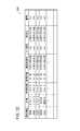
図11に示すように、コントローラ514は複数台(例えば3台)設けられており、それぞれLAN600によって接続されている。LAN600には使用履歴管理手段としてのホストコンピュータ602が接続されている。ホストコンピュータ602は、内部の記録手段に、図12に示す使用履歴テーブル604を記録しており、各コントローラ514に対して要求された個体番号に応じた使用履歴データを送受信し、集中的に管理する。ホストコンピュータ602は、コントローラ514から独立的な構成に限らず、いずれか1つのコントローラ514が使用履歴テーブル604を保持してホストコンピュータ602の処理を行ってもよい。 As shown in FIG. 11, a plurality of (for example, three)
また、LAN600は、有線、無線、電源ラインを用いたもの等であってもよく、その他の通信手段で代替してもよいことはもちろんである。LAN600は、かならずしもローカルな形態に限らず、例えば複数の医療施設で共同のネットワークを用いても良いし、ホストコンピュータ602をマニピュレータの製造メーカが用意し、一般のネットワークを介してコントローラ514と通信し、該製造メーカが履歴管理を代行してもよい。 Further, the
図12に示すように、使用履歴テーブル604は、個体情報欄、仕様欄、使用時間欄、仕様回数欄、滅菌処理日欄、エラー履歴欄、製造日欄及び備考欄を有する。また、これ以外にも位相修正値(又は原点修正値)等の固有情報を記録してもよい。個体情報欄は、作業部16の個体情報を示す。仕様欄は、作業部16の仕様を示し、具体的には先端動作部12の種類や、連結シャフト48の長さ等を示す。使用回数欄は、対応する作業部16が使用された回数を示す。滅菌処理欄は、対応する作業部16が最後に滅菌処理された日を示す。エラー履歴欄は、対応する作業部16において過去に発生したエラーの履歴の情報を示す。製造日欄は対応する作業部16の製造日を示す。備考欄はその他の情報を示す欄であり、任意の情報の書き込みが可能である。 As shown in FIG. 12, the usage history table 604 has an individual information column, a specification column, a usage time column, a specification count column, a sterilization processing date column, an error history column, a manufacturing date column, and a remarks column. In addition, unique information such as a phase correction value (or origin correction value) may be recorded. The individual information column indicates individual information of the working
滅菌処理欄及び備考欄の情報は、ホストコンピュータ602においてキーボード及びマウス等の入力手段により入力される。 The information in the sterilization processing column and the remarks column is input in the
図13に示すように、ホストコンピュータ602におけるモニタ602aには、接続情報テーブル606が表示される。接続情報テーブル606は、ホストコンピュータ602に接続されている3台のコントローラ514の各接続ポート1〜3についての情報が表示される。接続されているポートについては、使用履歴テーブル604を参照して接続情報テーブル606の対応する箇所に使用履歴データを表示する。接続されていない箇所については「未接続」と表示する。 As shown in FIG. 13, a connection information table 606 is displayed on the
各コントローラ514は、作業部検出手段107から得られる信号に基づいて、作業部16がアクチュエータブロック30に装着されたときにカメラ106及び白色LED105を制御してバーコード104の個体信号を取得し、該個体信号に対応した使用履歴データをホストコンピュータ602から取得する。また、作業部16がアクチュエータブロック30から取り外された後に使用履歴データを更新してホストコンピュータ602に供給し、該ホストコンピュータ602は取得した使用履歴データを個体信号に応じて使用履歴テーブル604に記録する。 Each
なお、使用履歴管理手段が設けられる場所としてはホストコンピュータ602に限らず、図11の仮想線で示すように、使用履歴管理手段と同等の機能を有する管理部608が、複数のコントローラ514のうちいずれか1つ、若しくは全部に備えられていてもよい。 Note that the place where the usage history management unit is provided is not limited to the
管理部608がコントローラ514のいずれか1つに設けられている場合には、該管理部608はホストコンピュータ602と同じように、他のコントローラ514と通信を行って情報の授受を行い、使用履歴テーブル604を集中管理する。 When the
管理部608が全てのコントローラ514に設けられている場合には、いずれか1つの管理部608を有効にする選択スイッチの操作を行い、他の管理部608は無効にしておくとよい。 When the
また、管理部608が全てのコントローラ514に設けられている場合には、使用履歴テーブル604に相当する情報を分散管理してもよい。例えば、所定の作業部16があるコントローラ514に接続されたときに、該コントローラ514では、他の全てのコントローラ514と通信を行い、接続された作業部16の個体情報に係る最新の使用履歴データを取得し、自らの管理部608で接続されている作業部16の情報の更新及び管理を行えばよい。情報を提供した側のコントローラ514では、該情報を削除し、又は送信済みであることを示すフラグを付加して管理するとよい。 When the
作業部16の使用履歴データは、作業部16が最後に接続された(又は現在接続されている)コントローラ514で更新及び管理してもよく、最初に接続されたコントローラ514で更新及び管理をしてもよく、又は全てのコントローラ514で冗長的に更新及び管理をしてもよい。 The usage history data of the
使用履歴テーブル604及び接続情報テーブル606の情報を表示する場合にはモニタ602aをコントローラ514に接続し、又は表示機としてホストコンピュータ602をLAN600に接続すればよい。 When displaying information in the usage history table 604 and the connection information table 606, the
次に、このように構成されるマニピュレータシステム500における個体情報の情報処理手順について説明する。以下の処理は、特段の断りのない場合には、コントローラ514において行われる。 Next, an information processing procedure for individual information in the
図14のステップS1において、コントローラ514は、作業部検出手段107から信号を取得し、操作部14のアクチュエータブロック30に作業部16が接続されたか否かを確認する。作業部16が接続されたときにはステップS2へ移り、未接続であるときには待機する。 In step S <b> 1 of FIG. 14, the
ステップS2において、カメラ106及び白色LED105を制御してバーコード104の情報を読み取る。この情報としては、個体情報、仕様、及び製造日等が挙げられる。これらの情報を取得した後、カメラ106及び白色LED105を停止させる。 In step S2, the
ステップS3において、ホストコンピュータ602と通信を行い、個体情報及び作業部16が接続されたポートの情報を送信してデータ送信要求を行う。ホストコンピュータ602は、取得した個体情報に基づいて使用履歴テーブル604を検索し、対応する仕様履歴データをコントローラ514に供給する。ホストコンピュータ602は、接続情報テーブル606における対応する欄に個体情報に応じた使用履歴データを表示する。 In step S3, communication with the
使用履歴テーブル604内に対応する個体情報がない場合、つまり新規の作業部16が接続された場合には、その旨をコントローラ514に通知するとともに、使用履歴テーブル604内に該個体情報用の欄を新たに設ける。 When there is no corresponding individual information in the usage history table 604, that is, when a
ステップS4において、ホストコンピュータ602から得られた情報に基づいて、使用時間のデータを変数Hrに代入し、使用回数のデータを変数Noに代入し、エラー履歴データを変数Erに代入する。ホストコンピュータ602に対応する個体情報の使用履歴データが存在しない旨の通知を受けた場合には、変数Hr、変数No及び変数Erにそれぞれ0を代入する。変数Erは、例えばエラーの種類数のビットを含む二進数データである。 In step S4, based on the information obtained from the
ステップS5において、所定のタイマーをスタートさせ、接続された作業部16の動作時間ΔHrをカウントする。動作時間ΔHrのカウントは、作業部16が動作モードであるときだけカウントアップするようにしてもよい。 In step S5, a predetermined timer is started, and the operating time ΔHr of the connected working
ステップS6において、所定のエラー検出処理を行い、エラーが発生した場合にはステップS7へ移り、エラーがない場合にはステップS8へ移る。 In step S6, a predetermined error detection process is performed. If an error has occurred, the process proceeds to step S7, and if there is no error, the process proceeds to step S8.
ステップS7において、発生したエラーに対する適切な対応の処理を行うとともに、変数Erにおける該エラーに対応するビットを「1」に設定する。これ以後、該ビットを参照することにより、そのエラーが発生したという履歴を認識可能となる。この後、ステップS8へ移る。 In step S7, an appropriate response process for the generated error is performed, and the bit corresponding to the error in the variable Er is set to “1”. Thereafter, the history that the error has occurred can be recognized by referring to the bit. Thereafter, the process proceeds to step S8.
ステップS8において、作業部検出手段107から信号を取得し、操作部14のアクチュエータブロック30から作業部16が取り外されたか否かを確認する。作業部16が取り外されたときにはステップS9へ移り、装着されているときにはステップS6へ戻る。 In step S <b> 8, a signal is acquired from the working
ステップS9において、タイマーを停止させてその時点の動作時間ΔHrを取得するとともに、変数Hrを、Hr←Hr+ΔHrと更新する。また、変数Noを、No←No+1とインクリメントする。 In step S9, the timer is stopped to acquire the current operating time ΔHr, and the variable Hr is updated as Hr ← Hr + ΔHr. Further, the variable No is incremented as No ← No + 1.
ステップS10において、ホストコンピュータ602と通信を行い、取り外された作業部16の個体情報、そのポートの情報、変数No、変数Hr及び変数Erを送信してデータ書き込み要求を行う。ホストコンピュータ602は、取得した個体情報に基づいて使用履歴テーブル604を検索し、対応する仕様履歴データの書き込みを行う。これにより、これ以後、3台のいずれのコントローラ514からデータ送信要求を受けた場合であっても、対応する作業部16の個体情報の正確な使用履歴データを供給することができる。この後、ステップS1へ戻る。 In step S10, communication with the
ホストコンピュータ602は、接続情報テーブル606における対応する欄の情報を非表示にして、「未使用」と表示する。 The
上述したように、本実施の形態に係るマニピュレータシステム500では、非接触のバーコード104及びカメラ106を用いることにより、作業部16の個体情報を取得することができるとともに、電力が不要であり、電気的接点もなく、作業部16を簡便に洗浄及び滅菌することができる。また、電気的接点がないことから、該接点の不良による通信エラーがない。一般に、非接触手段は電気的接点よりも高寿命である。 As described above, in the
バーコード104は各種の情報を画像情報として示し、非接触の通信を簡便に実現できる。 The
複数台のコントローラ514は、LAN600を介してホストコンピュータ602に接続されており、使用履歴テーブル604に対するアクセスが可能であることから、作業部16をいずれのコントローラ514に接続しても使用の経緯が分かることになり、好適である。 The plurality of
バーコード104は接続部15における後方に設けられており、バーコード104とカメラ106との距離を短くすることができ、個体情報が確実に供給される。 The
また、先端動作部12の姿勢は、例えば原点位置を基準として算出されることから、手術の途中で作業部を交換する場合には、次の作業に備えて先端動作部12及び作業部16の各プーリ50a〜50cは正確に原点に一致した軸位置としてから取り外すことが望ましい。原点位置に一致していない状態で取り外されたときには、所定の警報を発してその作業部を再装着するように促すとよいが、このとき別の作業部16を装着されることがないように作業部16を識別することが必要になる。このときに、バーコード104から得られる個体情報に基づいて作業部16を識別が可能になり、所定の警報を発生させることができる。 In addition, since the posture of the distal
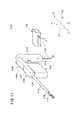
次に、マニピュレータ10の変形例に係るマニピュレータ10aについて図15を参照しながら説明する。マニピュレータ10aにおいてマニピュレータ10と同じ箇所には同符号を付して、その詳細な説明を省略する。マニピュレータ10aはバーコード104及びカメラ106に代えてRFID610及び送受信器612を設け、白色LED105を省略した形態である。 Next, a
図15に示すように、マニピュレータ10aの接続部15における後端部近傍にはRFID(Radio Frequency Identification(ID保持部))610が設けられている。RFIDとは微小なICチップに製品の個別情報を格納し、無線を利用して情報の読み取りや更新などを行う無線認証システムのことであり、無線タグ、ICタグ又はミューチップとも呼ばれる。RFID610には、前記のバーコード104に含まれる情報、つまり作業部16の個体情報、仕様、タイムスタンプ(製造日等)やシリアルナンバー、使用回数上限等の情報が含まれている。また、RFID610は書き込みが可能であり、使用回数、使用時間、エラー履歴、滅菌処理日、位相修正値(又は原点修正値)等の固有情報が記録されている。 As shown in FIG. 15, an RFID (Radio Frequency Identification (ID holding unit)) 610 is provided in the vicinity of the rear end of the
アクチュエータブロック30において、接続部15が接続された状態におけるRFID610に対向する位置には送受信器(ID認識部、データ送信部)612が設けられており、電波を用いてRFID610に対して送信及び受信を行う。接続部15がアクチュエータブロック30に装着された状態では、RFID610と送受信器612との相対的な位置及び向きは固定されていることから、それぞれの電波の指向性を狭くするとともに、指向性のメインローブを相手の方向に指向させて、その方向の電波を強くすると省電力で送受信が確実に行われる。また、メインローブ以外の方向には電波が弱くなり、無用に広い範囲に電波が達することがなく、混信の恐れがない。図15においては、RFID610及び送受信器612が発信及び受信する電波の強度及び感度の最も強い軸を仮想線614で示す。RFID610と送受信器612の双方の電波の指向性の最も強い方向が完全に一致していることが望ましいが、実際上は、例えばメインローブにおけるビーム幅で電力パターンが−3dBの範囲が相互に相手方を向くように設定するとよい。 In the
RFID610と送受信器612とは非常に接近しており、エネルギーの小さい短距離型を用いると、小電力化が図られるとともに混信の恐れがない。 The
このように、相対的な位置及び向きが固定されており、且つ近距離の通信をするためには、例えば13.56MHz帯、2.45GHz帯又は5GHz帯のRFIDを用いると好適である。 As described above, for example, a 13.56 MHz band, a 2.45 GHz band, or a 5 GHz band RFID is preferably used in order to perform communication at a short distance with a relative position and orientation fixed.
詳細な説明を省略するが、マニピュレータ10aを制御するコントローラ514は、RFID610及び送受信器612に対応した制御をする。また、RFIDはデータの書き込みが可能であることから、使用回数、使用時間、エラー履歴及び滅菌処理日等のデータを書き込んでもよい。RFIDにおける個体情報、シリアルナンバー、仕様等のデータについては、不用意に書き換えられることがないように所定の書換禁止手段を設けてもよい。 Although detailed description is omitted, the
マニピュレータ10aを制御するコントローラ514では、図16に示すような制御を行う。図16におけるステップS101〜S103は、前記のステップS1〜S3(図14参照)に相当し、ステップS105〜S111は、ステップS4〜S10に相当する。ステップS102では前記のステップS2と異なり、バーコード104に代えてRFID610から所定の情報を読み取る。 The
ステップS104は、ステップS103とステップS105の間に行われる処理であって、RFID610に必要な情報を書き込む。この情報は、ホストコンピュータ602における使用履歴テーブル604(図12参照)の対応する個体情報の使用履歴データの全てとする。 Step S104 is processing performed between step S103 and step S105, and necessary information is written in the
このような変形例に係るマニピュレータ10aを備えるシステムでは、非接触のRFID610及び送受信器612を用いることにより、作業部16の個体情報を取得することができるとともに、電気的接点が存在せず、しかもバッテリ等の蓄電体もない。従って作業部16を簡便に洗浄及び滅菌することができる。また、RFID610及び送受信器612は、電波を用いて各信号を送受信し、非接触の通信を簡便に実現できる。RFID610は小型簡便構成であり、通信を簡便に行うことができる。RFID610は、使用履歴データを受信して記録することにより、作業部16ごとの使用履歴の管理が容易となる。 In the system including the
送受信器612はアンテナである。送受信器612に接続される電気回路は操作部14又はコントローラ514のいずれに設けてもよい。 The
作業部16と操作部14との間の情報の伝達には、バーコード104(つまり画像情報)やRFID610(つまり電波)以外にも、磁気、光(例えば赤外線通信)を用いると非接触で個体情報を伝達することができ、作業部16の清掃、洗浄が容易となる。 In addition to the barcode 104 (that is, image information) and the RFID 610 (that is, radio wave), information is transmitted between the working
マニピュレータ10は医療用のものとして説明したが、使用用途はこれに限らず、例えば、エネルギー機器等の狭隘部補修の用途や、患者から離れた箇所から電気通信手段等を介して手技を行う遠隔操作機構に好適に適用可能であることはもちろんである。 Although the
次に、第2の実施形態に係る医療用のマニピュレータシステム1100について説明する。先ず、マニピュレータシステム1100の各構成要素と前記マニピュレータシステム500における対応する構成要素とを示す。 Next, a
つまり、マニピュレータシステム1100における次の主な構成要素、
マニピュレータ1102(a)、コントロールユニット1104(b)、外科器具1106(c)、外科器具コントロールユニット1112(d)、動作部コントローラ1107(e)、動作部1122(f)、シャフト1116(g)、ハンドル1110(h)、ボタン1114(i)、送信機1210(j)、モータ1212(k)、交信回路1216(l)、ドライブアセンブリ1204(m)、個体識別子1300(n)、個体信号読取器1302(o)は、順に前記のマニピュレータシステム500における次の構成要素、
マニピュレータ10(a)、コントローラ541(b)、作業部16(c)、アクチュエータブロック30(d)、接続部15(e)、先端動作部12(f)、連結シャフト48(g)、グリップハンドル26(h)、トリガーレバー32(i)、RFID610(j)、モータ41〜42(k)、送受信器612(l)、プーリ50a〜50c(m)、バーコード104(n)、カメラ106(o)に対応する。なお、括弧付きの符号は対比が容易となるように参考に付したものである。That is, the following main components in the manipulator system 1100:
Manipulator 1102 (a), control unit 1104 (b), surgical instrument 1106 (c), surgical instrument control unit 1112 (d), operating unit controller 1107 (e), operating unit 1122 (f), shaft 1116 (g), Handle 1110 (h), button 1114 (i), transmitter 1210 (j), motor 1212 (k), communication circuit 1216 (l), drive assembly 1204 (m), individual identifier 1300 (n), individual signal reader 1302 (o) is the next component in the
Manipulator 10 (a), controller 541 (b), working unit 16 (c), actuator block 30 (d), connecting unit 15 (e), tip operating unit 12 (f), connecting shaft 48 (g), grip handle 26 (h), trigger lever 32 (i), RFID 610 (j),
図18には第2の実施形態に係るマニピュレータシステム1100が示される。マニピュレータシステム1100は医療用のマニピュレータ1102とコントロールユニット1104を含む。マニピュレータ1102は外科器具(作業部)1106と外科器具コントロール機構1108を含む。外科器具1106は動作部コントローラ1107、動作部1122とシャフト1116を含む。シャフト1116は第一端1118とその反対側の第二端1120を持つ。動作部1122はシャフト1116の第一端1118にマウントされ、現在そして将来に亘り当業者に知られる様々な動作を行う。動作部コントローラ1107はシャフト1116の第二端1120にマウントされ、現在そして将来に亘り当業者に知られる様々な動作を行う。本明細書中で使用されるマウントという表現は、一緒にする(join)、係合する(engage)、一体化する(unite)、接続する(connect)、関係付ける(associate)、挿入する(insert)、吊るす(hang)、保持する(hold)、固定する(affix)、添付する(attach)、締める(fasten)、束ねる(bind)、貼る(paste)、留める(secure)、締める(bolt)、ねじる(screw)、留める(rivet)、はんだ付けする(solder)、溶接する(weld)、そして他の類似の用語を含む。 FIG. 18 shows a
外科器具コントロール機構1108は、現在から将来に亘って当業者に知られる機械的、電気機械的、電気的な機構である。外科器具コントロール機構1108はハンドル1110と外科器具コントロールユニット(アクチュエータ部)1112を含む。外科医は現在そして将来において知られる低侵襲外科手術を動作部1122を使って行うためハンドル1110を操作する。ハンドル1110は回転、抑え付け、トグル等、動作部1122に所望の動作を行わせるための機構を含む。例えば、ハンドル1110は動作部1122を開けたり閉じたりするボタン1114を持つ。外科器具コントロール機構1108はハーネス1115を通して電気的にコントロールユニット1104と接続されている。 Surgical
コントロールユニット1104は、電気的信号をハーネス1115を通して、外科器具コントロール機構1108から受けたりあるいは送ったりする。これにより動作部コントローラ1107を通して動作部の動きをコントロールする。例えば、コントロールソフトウエアがボタン1114の動作が示す電気信号を受け、これを動作部1122を動かすための適切な信号へ変換する。電気信号はアナログでもデジタルでもよい。動作部1122をコントロールする外科器具コントロール機構1108へ送られるコントロール指令を決定するために、ハンドル1110にマウントされているトランスデューサから受けた角度測定値をコントロールユニット1104はさらに変換する。 The
図19において、動作部コントローラ1107は、複数のドライブアセンブリ1204、複数のワイヤ1206、複数のコネクタ1208そして送信機(ID保持部)1210を含む。送信機1210はRFIDを含む。一般的にシャフト1116はその中に複数のワイヤ1206が延びる細長い管を含む。複数のワイヤ1206は、動作部1122と動作部コントローラ1107とを操作可能につなぐ。動作部1122は切断、剥離、縫合、把持等の目的のため様々なタイプの器具を持つ。 In FIG. 19, the
図18において、外科器具コントロール機構1108は、外科器具コントロールユニット1112内に複数のモータ1212、複数の電気ケーブル1214、交信回路(ID認識部)1216、コントロールケーブル1218をマウントする。交信回路1216は受信機を持つ。外科器具1106が外科器具コントロール機構1108にマウントされたとき、送信機1210は固体認識信号を交信回路1216へ送る。個体認識信号は動作部1122の型を特定し、そしてマニピュレータシステム1100は所望の動作を行う。交信回路1216は固体認識信号を受け取り、ハーネス1115内のコントロールケーブル1218を通してその固体認識信号をコントロールユニット1104へ送る。 In FIG. 18, the surgical
コントロールユニット1104は固体認識信号を交信回路1216から受け取る。コントロールユニット1104は認識された外科器具の種類に従ってその動きを理解し、ハーネス1115の中にある複数の電気ケーブル1214を通して複数のモータ1212へ制御信号を送る。外科器具1106は外科器具コントロール機構1108から離脱可能であり、複数の異なった種類の外科器具が簡単に迅速に取り付け換えられる。外科器具コントロール機構1108と外科器具1106を物理的に接続する複数のコネクタ1208を介して複数のモータ1212は取り外し可能に複数のドライブアセンブリ1204に結合している。 The
複数のドライブアセンブリ1204はコントロールユニット1104から動作部1122の機械的動作へ信号を伝える機械的構成部分を含む。例えば、複数のモータ1212は複数のドライブアセンブリ1204を回転させる回転トルクを発生する。複数のドライブアセンブリ1204の回転は動作部1122の動きを起こす複数のワイヤ1206の動きとなる。動作部1122は複数の異なった、例えば切断、解体、縫合等の器具を持つので、複数のワイヤ1206は動作部1122の異なった動きに対応する。よって、コントロールユニット1104は、動作部の種類を認識し、それに基づき適当なコントロール信号を発生する。 The plurality of
図19で示されるように、動作部コントローラ1107は複数のドライブアセンブリ1204、複数のワイヤ1206、複数のコネクタ1208そして個体識別子(ID保持部)1300を含む。個体識別子1300は外科器具1106の外側表面にマウントされる。例えば、個体識別子1300は外科器具コントロール機構1108に隣接する動作部コントローラ1107の外側表面にマウントされる。個体識別子1300は現在または将来において当業者に知られるバーコード等を含む。外科器具コントロール機構1108は外科器具コントロールユニット1112にマウントされている複数のモータ1212、複数の電気ケーブル1214、個体信号読取器(ID認識部)1302そしてコントロールケーブル1218を含む。個体信号読取器1302は、赤外線を使って個体識別子1300の個体信号を読み取るバーコードリーダを含む。外科器具1106が外科器具コントロール機構1108にマウントされたとき、個体信号読取器1302は、個体識別子1300の個体信号を読み取り、ハーネス1115内のコントロールケーブル1218を通してコントロールユニット1104へ個体識別子1300の個体信号を伝える。コントロールユニット1104は、個体信号を個体信号読取器1302から受け取る。コントロールユニット(制御部)1104は動作部の種類を認識し、その動きを理解し、図19で説明したようにハーネス1115の中の複数の電気ケーブル1214を通して複数のモータ1212へコントロール信号を送る。 As shown in FIG. 19, the
このような、マニピュレータシステム1100によれば、動作部コントローラ1107と外科器具コントロール機構1108との間で個体情報を非接触で伝達することができ、動作部コントローラ1107は電気的接点のない構成となり、洗浄及び滅菌を容易に行うことができる。 According to such a
作業部16は、人手で操作をする操作部14に接続されるものとして説明したが、例えば図20に示すような手術用ロボットシステム700に適用してもよい。 Although the working
手術用ロボットシステム700は、ロボットアーム702と、コンソール704とを有し、作業部16はロボットアーム702の先端に接続されている。ロボットアーム702の先端には前記のアクチュエータブロック30と同じ機構を設けることにより、作業部16を接続及び駆動可能である。この場合のマニピュレータ10は、ロボットアーム702と作業部16とからなる。ロボットアーム702は、作業部16を移動させる手段であればよく、据置型に限らず、例えば自律移動型でもよい。コンソール704は、テーブル型、制御盤型等の構成を採りうる。 The
ロボットアーム702は、独立的な6以上の関節(回転軸やスライド軸等)を有すると、作業部16の位置及び向きを任意に設定できて好適である。先端のアクチュエータブロック30は、ロボットアーム702の先端部708と一体化している。 If the
アクチュエータブロック30には、カメラ106(又は送受信器612)、白色LED105及び作業部検出手段107が設けられ、作業部16の接続部15には、バーコード104(又はRFID610)及び被検出片109が設けられている。 The
ロボットアーム702は、コンソール704の作用下に動作し、プログラムによる自動動作や、コンソール704に設けられたジョイスティック(ロボット操作部)706に倣った動作、及びこれらの複合的な動作をする構成にしてもよい。コンソール704は、前記のコントローラ514の機能を含んでいる。 The
コンソール704には、前記操作部14のうちアクチュエータブロック30を除いた機構の操作部としての2つのジョイスティック706と、モニタ710が設けられている。図示を省略するが、2つのジョイスティック706により、2台のロボットアーム702を個別に操作が可能である。2つのジョイスティック706は、両手で操作しやすい位置に設けられている。モニタ710には、内視鏡による画像等の情報が表示される。 The
ジョイスティック706は、上下動作、左右動作、捻り動作、及び傾動動作が可能であり、これらの動作に応じてロボットアーム702を動かすことができる。ジョイスティック706はマスターアームであってもよい。ロボットアーム702とコンソール704との間の通信手段は、有線、無線、ネットワーク又はこれらの組合わせでよい。 The
本発明に係るマニピュレータシステムは、上述の実施の形態に限らず、本発明の要旨を逸脱することなく、種々の構成を採り得ることはもちろんである。 Of course, the manipulator system according to the present invention is not limited to the above-described embodiment, and can adopt various configurations without departing from the gist of the present invention.
10、1102…マニピュレータ 12…先端動作部
14、14a〜14d…操作部 15…接続部
16、16a〜16d…作業部 30…アクチュエータブロック
37…カバー 40、41、42、1212…モータ
48…連結シャフト 104…バーコード(ID保持部)
105…LED(投光手段) 106…カメラ(ID認識部)
107…作業部検出手段 107a…投光器
107b…受光器 109…被検出片
300…プーリ格納体 500、1100…マニピュレータシステム
514…コントローラ 600…LAN
602…ホストコンピュータ 604…使用履歴テーブル
606…接続情報テーブル 610…RFID(ID保持部)
612…送受信器(ID認識部) 700…手術用ロボットシステム
1104…コントロールユニット 1106…外科器具(作業部)
1107…動作部コントローラ(接続部)
1108…外科器具コントロール機構(操作部)
1112…外科器具コントロールユニット(アクチュエータ部)
1116…シャフト 1122…動作部
1210…送信機(ID保持部) 1216…交信回路(ID認識部)
1300…個体識別子(ID保持部)
1302…個体信号読取器(ID認識部)DESCRIPTION OF
105 ... LED (light projection means) 106 ... Camera (ID recognition unit)
DESCRIPTION OF
602: Host computer 604: Usage history table 606: Connection information table 610: RFID (ID holding unit)
612 ... Transmitter / receiver (ID recognition unit) 700 ... Robot system for
1107: Operation unit controller (connection unit)
1108: Surgical instrument control mechanism (operation unit)
1112 ... Surgical instrument control unit (actuator part)
1116 ...
1300: Individual identifier (ID holding unit)
1302 ... Individual signal reader (ID recognition unit)
Claims (15)
Translated fromJapanese前記マニピュレータは、
アクチュエータが備えられたアクチュエータ部と、
前記アクチュエータ部に対して着脱自在で、シャフトの先端に前記アクチュエータに連動して前記シャフト軸と非平行な軸を基準として回動する先端動作部を備える作業部と、
を有し、
前記作業部は、固体識別用の個体信号を保持するID保持部を備え、
前記アクチュエータ部は、前記ID保持部に対して非接触で、該ID保持部の前記個体信号を認識し前記制御部へ供給するID認識部を備え、
前記制御部は、供給された前記個体信号に基づいて前記作業部の制御をすることを特徴とするマニピュレータシステム。In a manipulator system comprising a manipulator and a control unit that controls the manipulator,
The manipulator
An actuator unit provided with an actuator;
A working unit that is detachable from the actuator unit and includes a tip operating unit that rotates at the tip of a shaft with reference to an axis that is non-parallel to the shaft axis in conjunction with the actuator;
Have
The working unit includes an ID holding unit that holds an individual signal for solid identification,
The actuator unit includes an ID recognition unit that is in non-contact with the ID holding unit, recognizes the individual signal of the ID holding unit, and supplies the signal to the control unit.
The said control part controls the said working part based on the supplied said individual signal, The manipulator system characterized by the above-mentioned.
前記ID保持部は、電波を用いて前記個体信号を送信する送信機であり、
前記ID認識部は、前記保持部が送信する前記個体信号を受信する受信機であることを特徴とするマニピュレータシステム。The manipulator system according to claim 1, wherein
The ID holding unit is a transmitter that transmits the individual signal using radio waves,
The manipulator system, wherein the ID recognition unit is a receiver that receives the individual signal transmitted by the holding unit.
前記ID保持部は、RFIDであることを特徴とするマニピュレータシステム。The manipulator system according to claim 2, wherein
The manipulator system, wherein the ID holding unit is an RFID.
前記RFIDは、13.56MHz帯、2.45GHz帯又は5GHz帯の仕様であり、電波の指向性の最も強いメインローブのビーム幅で電力パターンが−3dBの範囲が前記ID認識部を指向していることを特徴とするマニピュレータシステム。The manipulator system according to claim 3, wherein
The RFID has specifications of 13.56 MHz band, 2.45 GHz band, or 5 GHz band, and the main lobe beam width with the strongest directivity of radio waves has a power pattern of −3 dB toward the ID recognition unit. A manipulator system characterized by
前記アクチュエータ部は、マニピュレータシステムに係る使用履歴データを電波で送信するデータ送信部を有し、
前記RFIDは、前記使用履歴データを受信して記録手段に記録することを特徴とするマニピュレータシステム。The manipulator system according to claim 3, wherein
The actuator unit has a data transmission unit that transmits usage history data related to a manipulator system by radio waves,
The RFID receives and records the usage history data in a recording means.
前記ID保持部は、前記個体信号を画像情報として保持する表示手段であり、
前記ID認識部は、前記表示手段を撮像する撮像手段であることを特徴とするマニピュレータシステム。The manipulator system according to claim 1, wherein
The ID holding unit is a display unit that holds the individual signal as image information,
The manipulator system, wherein the ID recognition unit is an imaging unit that images the display unit.
前記表示手段は、バーコードであることを特徴とするマニピュレータシステム。The manipulator system according to claim 6, wherein
The manipulator system, wherein the display means is a bar code.
前記作業部及び(又は)前記アクチュエータ部は、前記作業部と前記アクチュエータ部とが接続されたときに前記表示手段及び前記撮像手段が略閉空間内となるように前記ID保持部及び前記撮像手段を覆うカバーを有することを特徴とするマニピュレータシステム。The manipulator system according to claim 6, wherein
The working unit and / or the actuator unit includes the ID holding unit and the imaging unit so that the display unit and the imaging unit are in a substantially closed space when the working unit and the actuator unit are connected. A manipulator system having a cover for covering.
前記撮像手段は、赤外線を検出する手段であることを特徴とするマニピュレータシステム。The manipulator system according to claim 6, wherein
The manipulator system characterized in that the imaging means is means for detecting infrared rays.
前記アクチュエータ部は、前記表示手段を照明する投光手段を有することを特徴とするマニピュレータシステム。The manipulator system according to claim 6, wherein
The manipulator system, wherein the actuator unit includes a light projecting unit that illuminates the display unit.
前記アクチュエータ部は、前記作業部の有無を検出する作業部検出手段を有し、
前記制御部は、前記作業部検出手段から得られる信号に基づいて、前記作業部が前記アクチュエータ部に装着されたときに前記ID認識部を制御して前記ID保持部の前記個体信号を取得することを特徴とするマニピュレータシステム。The manipulator system according to claim 1, wherein
The actuator unit has a working unit detecting means for detecting the presence or absence of the working unit,
The control unit controls the ID recognition unit to acquire the individual signal of the ID holding unit when the working unit is attached to the actuator unit based on a signal obtained from the working unit detection unit. A manipulator system characterized by this.
前記作業部検出手段は、対向する位置に設けられた投光器と受光器とからなり、該投光器と該受光器との間に前記作業部の一部が挿入されて遮光することにより該作業部が装着されたことを検出することを特徴とするマニピュレータシステム。The manipulator system according to claim 11, wherein
The working unit detecting means includes a projector and a light receiver provided at opposing positions, and the working unit is shielded by inserting a part of the working unit between the projector and the light receiver to shield the light. A manipulator system characterized by detecting attachment.
複数の前記制御部と通信可能な使用履歴管理手段を有し、
前記アクチュエータ部は、前記作業部の有無を検出する作業部検出手段を有し、
前記制御部は、前記作業部検出手段から得られる信号に基づいて、前記作業部が前記アクチュエータ部に装着されたときに前記ID認識部を制御して前記ID保持部の前記個体信号を取得し、該個体信号に対応した使用履歴データを前記使用履歴管理手段から取得し、前記作業部が前記アクチュエータ部から取り外された後に前記使用履歴データを更新して前記使用履歴管理手段に供給し、該使用履歴管理手段は取得した使用履歴データを前記個体信号に応じて記録手段に記録することを特徴とするマニピュレータシステム。The manipulator system according to claim 1, wherein
Use history management means capable of communicating with a plurality of the control unit,
The actuator unit has a working unit detecting means for detecting the presence or absence of the working unit,
The control unit controls the ID recognition unit to acquire the individual signal of the ID holding unit when the working unit is attached to the actuator unit based on a signal obtained from the working unit detection unit. Obtaining usage history data corresponding to the individual signal from the usage history management means, updating the usage history data after the working unit is removed from the actuator unit, and supplying the usage history data to the usage history management unit, The use history management means records the acquired use history data in a recording means in accordance with the individual signal.
前記使用履歴管理手段は、複数の前記制御部のうちいずれか1つ、若しくは全部に備えられていることを特徴とするマニピュレータシステム。The manipulator system according to claim 13,
The manipulator system, wherein the use history management means is provided in any one or all of the plurality of control units.
前記作業部は、前記先端動作部と前記アクチュエータ部に接続される接続部とが前記シャフトにより連結され、
前記ID保持部は前記接続部に設けられていることを特徴とするマニピュレータシステム。The manipulator system according to claim 1, wherein
The working unit is connected to the tip operating unit and a connecting unit connected to the actuator unit by the shaft,
The manipulator system, wherein the ID holding unit is provided in the connection unit.
Priority Applications (8)
| Application Number | Priority Date | Filing Date | Title |
|---|---|---|---|
| JP2007206850AJP5085996B2 (en) | 2006-10-25 | 2007-08-08 | Manipulator system |
| EP09150318AEP2042120B1 (en) | 2006-10-25 | 2007-10-24 | Manipulator system |
| EP07119215AEP1915967B1 (en) | 2006-10-25 | 2007-10-24 | Manipulator system |
| AT07119215TATE460128T1 (en) | 2006-10-25 | 2007-10-24 | MANIPULATOR SYSTEM |
| AT09150318TATE555738T1 (en) | 2006-10-25 | 2007-10-24 | MANIPULATOR SYSTEM |
| DE602007005200TDE602007005200D1 (en) | 2006-10-25 | 2007-10-24 | manipulator system |
| US11/923,124US20080262654A1 (en) | 2006-10-25 | 2007-10-24 | Manipulator system |
| CN2007101674711ACN101167658B (en) | 2006-10-25 | 2007-10-25 | Manipulator system |
Applications Claiming Priority (3)
| Application Number | Priority Date | Filing Date | Title |
|---|---|---|---|
| US86282306P | 2006-10-25 | 2006-10-25 | |
| US60/862823 | 2006-10-25 | ||
| JP2007206850AJP5085996B2 (en) | 2006-10-25 | 2007-08-08 | Manipulator system |
Publications (2)
| Publication Number | Publication Date |
|---|---|
| JP2008104855Atrue JP2008104855A (en) | 2008-05-08 |
| JP5085996B2 JP5085996B2 (en) | 2012-11-28 |
Family
ID=39388510
Family Applications (1)
| Application Number | Title | Priority Date | Filing Date |
|---|---|---|---|
| JP2007206850AExpired - Fee RelatedJP5085996B2 (en) | 2006-10-25 | 2007-08-08 | Manipulator system |
Country Status (6)
| Country | Link |
|---|---|
| US (1) | US20080262654A1 (en) |
| EP (2) | EP2042120B1 (en) |
| JP (1) | JP5085996B2 (en) |
| CN (1) | CN101167658B (en) |
| AT (2) | ATE460128T1 (en) |
| DE (1) | DE602007005200D1 (en) |
Cited By (15)
| Publication number | Priority date | Publication date | Assignee | Title |
|---|---|---|---|---|
| JP2009213653A (en)* | 2008-03-10 | 2009-09-24 | Terumo Corp | Manipulator |
| JP2009226029A (en)* | 2008-03-24 | 2009-10-08 | Terumo Corp | Manipulator |
| JP2012061195A (en)* | 2010-09-17 | 2012-03-29 | Terumo Corp | Medical manipulator |
| EP2484304A2 (en) | 2011-02-03 | 2012-08-08 | Terumo Kabushiki Kaisha | Medical manipulator system |
| JP2013542768A (en)* | 2010-10-08 | 2013-11-28 | コーニンクレッカ フィリップス エヌ ヴェ | Flexible leash with integrated sensors for dynamic instrument tracking |
| WO2015194333A1 (en)* | 2014-06-17 | 2015-12-23 | オリンパス株式会社 | Medical treatment system setting method |
| JP2015536738A (en)* | 2012-12-07 | 2015-12-24 | ユニバーシティ オブ ヒューストン | Surgical procedure management system and method |
| JP2018509966A (en)* | 2015-02-27 | 2018-04-12 | エシコン エルエルシーEthicon LLC | Surgical device configured to track end-of-life parameters |
| JP2019024609A (en)* | 2017-07-26 | 2019-02-21 | Dgshape株式会社 | Cleaning management system for surgical operation set |
| US10258420B2 (en) | 2014-02-25 | 2019-04-16 | Olympus Corporation | Surgical manipulator system |
| JP2019535389A (en)* | 2016-11-11 | 2019-12-12 | インテュイティブ サージカル オペレーションズ, インコーポレイテッド | Teleoperated surgical system with surgical instrument wear tracking |
| JP2020032161A (en)* | 2018-08-28 | 2020-03-05 | 株式会社メディカロイド | Driving unit interface, adapter, and method of detecting attachment of surgical instrument to driving unit interface |
| US10881475B2 (en) | 2015-07-09 | 2021-01-05 | Kawasaki Jukogyo Kabushiki Kaisha | Surgical robot |
| JP2021500999A (en)* | 2017-10-30 | 2021-01-14 | エシコン エルエルシーEthicon LLC | Surgical instrument system with handle configuration |
| JP2021531853A (en)* | 2018-07-10 | 2021-11-25 | インテュイティブ サージカル オペレーションズ, インコーポレイテッド | Systems and methods for tool detection and related control modes |
Families Citing this family (851)
| Publication number | Priority date | Publication date | Assignee | Title |
|---|---|---|---|---|
| US6793652B1 (en) | 1999-06-02 | 2004-09-21 | Power Medical Interventions, Inc. | Electro-mechanical surgical device |
| US10285694B2 (en) | 2001-10-20 | 2019-05-14 | Covidien Lp | Surgical stapler with timer and feedback display |
| US9510740B2 (en)* | 2002-03-12 | 2016-12-06 | Karl Storz Endovision, Inc. | Auto recognition of a shaver blade for medical use |
| US8723936B2 (en) | 2002-03-12 | 2014-05-13 | Karl Storz Imaging, Inc. | Wireless camera coupling with rotatable coupling |
| US20070084897A1 (en) | 2003-05-20 | 2007-04-19 | Shelton Frederick E Iv | Articulating surgical stapling instrument incorporating a two-piece e-beam firing mechanism |
| US9060770B2 (en) | 2003-05-20 | 2015-06-23 | Ethicon Endo-Surgery, Inc. | Robotically-driven surgical instrument with E-beam driver |
| US10041822B2 (en) | 2007-10-05 | 2018-08-07 | Covidien Lp | Methods to shorten calibration times for powered devices |
| US11311291B2 (en) | 2003-10-17 | 2022-04-26 | Covidien Lp | Surgical adapter assemblies for use between surgical handle assembly and surgical end effectors |
| US10022123B2 (en) | 2012-07-09 | 2018-07-17 | Covidien Lp | Surgical adapter assemblies for use between surgical handle assembly and surgical end effectors |
| US10105140B2 (en)* | 2009-11-20 | 2018-10-23 | Covidien Lp | Surgical console and hand-held surgical device |
| US10588629B2 (en)* | 2009-11-20 | 2020-03-17 | Covidien Lp | Surgical console and hand-held surgical device |
| US9072535B2 (en) | 2011-05-27 | 2015-07-07 | Ethicon Endo-Surgery, Inc. | Surgical stapling instruments with rotatable staple deployment arrangements |
| US8215531B2 (en) | 2004-07-28 | 2012-07-10 | Ethicon Endo-Surgery, Inc. | Surgical stapling instrument having a medical substance dispenser |
| US11890012B2 (en) | 2004-07-28 | 2024-02-06 | Cilag Gmbh International | Staple cartridge comprising cartridge body and attached support |
| US11998198B2 (en) | 2004-07-28 | 2024-06-04 | Cilag Gmbh International | Surgical stapling instrument incorporating a two-piece E-beam firing mechanism |
| US7947034B2 (en) | 2004-07-30 | 2011-05-24 | Tyco Healthcare Group Lp | Flexible shaft extender and method of using same |
| US11291443B2 (en) | 2005-06-03 | 2022-04-05 | Covidien Lp | Surgical stapler with timer and feedback display |
| US11751873B2 (en) | 2005-07-26 | 2023-09-12 | Cilag Gmbh International | Electrically powered surgical instrument with manual release |
| US9662116B2 (en) | 2006-05-19 | 2017-05-30 | Ethicon, Llc | Electrically self-powered surgical instrument with cryptographic identification of interchangeable part |
| US8579176B2 (en) | 2005-07-26 | 2013-11-12 | Ethicon Endo-Surgery, Inc. | Surgical stapling and cutting device and method for using the device |
| US7959050B2 (en)* | 2005-07-26 | 2011-06-14 | Ethicon Endo-Surgery, Inc | Electrically self-powered surgical instrument with manual release |
| US7479608B2 (en) | 2006-05-19 | 2009-01-20 | Ethicon Endo-Surgery, Inc. | Force switch |
| US8573462B2 (en) | 2006-05-19 | 2013-11-05 | Ethicon Endo-Surgery, Inc. | Electrical surgical instrument with optimized power supply and drive |
| US9554803B2 (en) | 2005-07-26 | 2017-01-31 | Ethicon Endo-Surgery, Llc | Electrically self-powered surgical instrument with manual release |
| US10314583B2 (en) | 2005-07-26 | 2019-06-11 | Ethicon Llc | Electrically self-powered surgical instrument with manual release |
| US8627993B2 (en) | 2007-02-12 | 2014-01-14 | Ethicon Endo-Surgery, Inc. | Active braking electrical surgical instrument and method for braking such an instrument |
| US8627995B2 (en)* | 2006-05-19 | 2014-01-14 | Ethicon Endo-Sugery, Inc. | Electrically self-powered surgical instrument with cryptographic identification of interchangeable part |
| US11484312B2 (en) | 2005-08-31 | 2022-11-01 | Cilag Gmbh International | Staple cartridge comprising a staple driver arrangement |
| US10159482B2 (en) | 2005-08-31 | 2018-12-25 | Ethicon Llc | Fastener cartridge assembly comprising a fixed anvil and different staple heights |
| US11246590B2 (en) | 2005-08-31 | 2022-02-15 | Cilag Gmbh International | Staple cartridge including staple drivers having different unfired heights |
| US7669746B2 (en) | 2005-08-31 | 2010-03-02 | Ethicon Endo-Surgery, Inc. | Staple cartridges for forming staples having differing formed staple heights |
| US7673781B2 (en) | 2005-08-31 | 2010-03-09 | Ethicon Endo-Surgery, Inc. | Surgical stapling device with staple driver that supports multiple wire diameter staples |
| US8800838B2 (en) | 2005-08-31 | 2014-08-12 | Ethicon Endo-Surgery, Inc. | Robotically-controlled cable-based surgical end effectors |
| US9237891B2 (en) | 2005-08-31 | 2016-01-19 | Ethicon Endo-Surgery, Inc. | Robotically-controlled surgical stapling devices that produce formed staples having different lengths |
| US7934630B2 (en) | 2005-08-31 | 2011-05-03 | Ethicon Endo-Surgery, Inc. | Staple cartridges for forming staples having differing formed staple heights |
| US20070106317A1 (en) | 2005-11-09 | 2007-05-10 | Shelton Frederick E Iv | Hydraulically and electrically actuated articulation joints for surgical instruments |
| US8011905B2 (en) | 2005-11-17 | 2011-09-06 | Novartis Ag | Surgical cassette |
| US11793518B2 (en) | 2006-01-31 | 2023-10-24 | Cilag Gmbh International | Powered surgical instruments with firing system lockout arrangements |
| US8708213B2 (en) | 2006-01-31 | 2014-04-29 | Ethicon Endo-Surgery, Inc. | Surgical instrument having a feedback system |
| US8186555B2 (en) | 2006-01-31 | 2012-05-29 | Ethicon Endo-Surgery, Inc. | Motor-driven surgical cutting and fastening instrument with mechanical closure system |
| US7753904B2 (en) | 2006-01-31 | 2010-07-13 | Ethicon Endo-Surgery, Inc. | Endoscopic surgical instrument with a handle that can articulate with respect to the shaft |
| US8763879B2 (en) | 2006-01-31 | 2014-07-01 | Ethicon Endo-Surgery, Inc. | Accessing data stored in a memory of surgical instrument |
| US20110024477A1 (en) | 2009-02-06 | 2011-02-03 | Hall Steven G | Driven Surgical Stapler Improvements |
| US11278279B2 (en) | 2006-01-31 | 2022-03-22 | Cilag Gmbh International | Surgical instrument assembly |
| US8820603B2 (en) | 2006-01-31 | 2014-09-02 | Ethicon Endo-Surgery, Inc. | Accessing data stored in a memory of a surgical instrument |
| US8161977B2 (en) | 2006-01-31 | 2012-04-24 | Ethicon Endo-Surgery, Inc. | Accessing data stored in a memory of a surgical instrument |
| US7845537B2 (en) | 2006-01-31 | 2010-12-07 | Ethicon Endo-Surgery, Inc. | Surgical instrument having recording capabilities |
| US20120292367A1 (en) | 2006-01-31 | 2012-11-22 | Ethicon Endo-Surgery, Inc. | Robotically-controlled end effector |
| US20110295295A1 (en) | 2006-01-31 | 2011-12-01 | Ethicon Endo-Surgery, Inc. | Robotically-controlled surgical instrument having recording capabilities |
| US9861359B2 (en) | 2006-01-31 | 2018-01-09 | Ethicon Llc | Powered surgical instruments with firing system lockout arrangements |
| US11224427B2 (en) | 2006-01-31 | 2022-01-18 | Cilag Gmbh International | Surgical stapling system including a console and retraction assembly |
| US8992422B2 (en) | 2006-03-23 | 2015-03-31 | Ethicon Endo-Surgery, Inc. | Robotically-controlled endoscopic accessory channel |
| US8236010B2 (en) | 2006-03-23 | 2012-08-07 | Ethicon Endo-Surgery, Inc. | Surgical fastener and cutter with mimicking end effector |
| US8322455B2 (en) | 2006-06-27 | 2012-12-04 | Ethicon Endo-Surgery, Inc. | Manually driven surgical cutting and fastening instrument |
| US7443296B2 (en)* | 2006-07-21 | 2008-10-28 | Alcon, Inc. | Smart connector system for surgical machine |
| US10568652B2 (en) | 2006-09-29 | 2020-02-25 | Ethicon Llc | Surgical staples having attached drivers of different heights and stapling instruments for deploying the same |
| US10130359B2 (en) | 2006-09-29 | 2018-11-20 | Ethicon Llc | Method for forming a staple |
| US7506791B2 (en) | 2006-09-29 | 2009-03-24 | Ethicon Endo-Surgery, Inc. | Surgical stapling instrument with mechanical mechanism for limiting maximum tissue compression |
| US11980366B2 (en) | 2006-10-03 | 2024-05-14 | Cilag Gmbh International | Surgical instrument |
| JP5085996B2 (en) | 2006-10-25 | 2012-11-28 | テルモ株式会社 | Manipulator system |
| US11291441B2 (en) | 2007-01-10 | 2022-04-05 | Cilag Gmbh International | Surgical instrument with wireless communication between control unit and remote sensor |
| US8632535B2 (en) | 2007-01-10 | 2014-01-21 | Ethicon Endo-Surgery, Inc. | Interlock and surgical instrument including same |
| US8459520B2 (en) | 2007-01-10 | 2013-06-11 | Ethicon Endo-Surgery, Inc. | Surgical instrument with wireless communication between control unit and remote sensor |
| US8684253B2 (en) | 2007-01-10 | 2014-04-01 | Ethicon Endo-Surgery, Inc. | Surgical instrument with wireless communication between a control unit of a robotic system and remote sensor |
| US8652120B2 (en) | 2007-01-10 | 2014-02-18 | Ethicon Endo-Surgery, Inc. | Surgical instrument with wireless communication between control unit and sensor transponders |
| US20080169333A1 (en) | 2007-01-11 | 2008-07-17 | Shelton Frederick E | Surgical stapler end effector with tapered distal end |
| US11039836B2 (en) | 2007-01-11 | 2021-06-22 | Cilag Gmbh International | Staple cartridge for use with a surgical stapling instrument |
| US7673782B2 (en) | 2007-03-15 | 2010-03-09 | Ethicon Endo-Surgery, Inc. | Surgical stapling instrument having a releasable buttress material |
| US8893946B2 (en) | 2007-03-28 | 2014-11-25 | Ethicon Endo-Surgery, Inc. | Laparoscopic tissue thickness and clamp load measuring devices |
| US8931682B2 (en) | 2007-06-04 | 2015-01-13 | Ethicon Endo-Surgery, Inc. | Robotically-controlled shaft based rotary drive systems for surgical instruments |
| US7832408B2 (en) | 2007-06-04 | 2010-11-16 | Ethicon Endo-Surgery, Inc. | Surgical instrument having a directional switching mechanism |
| US11564682B2 (en) | 2007-06-04 | 2023-01-31 | Cilag Gmbh International | Surgical stapler device |
| US8534528B2 (en) | 2007-06-04 | 2013-09-17 | Ethicon Endo-Surgery, Inc. | Surgical instrument having a multiple rate directional switching mechanism |
| US7905380B2 (en) | 2007-06-04 | 2011-03-15 | Ethicon Endo-Surgery, Inc. | Surgical instrument having a multiple rate directional switching mechanism |
| US8408439B2 (en) | 2007-06-22 | 2013-04-02 | Ethicon Endo-Surgery, Inc. | Surgical stapling instrument with an articulatable end effector |
| US7753245B2 (en) | 2007-06-22 | 2010-07-13 | Ethicon Endo-Surgery, Inc. | Surgical stapling instruments |
| US11849941B2 (en) | 2007-06-29 | 2023-12-26 | Cilag Gmbh International | Staple cartridge having staple cavities extending at a transverse angle relative to a longitudinal cartridge axis |
| AU2008302043B2 (en) | 2007-09-21 | 2013-06-27 | Covidien Lp | Surgical device |
| US10498269B2 (en) | 2007-10-05 | 2019-12-03 | Covidien Lp | Powered surgical stapling device |
| US10779818B2 (en) | 2007-10-05 | 2020-09-22 | Covidien Lp | Powered surgical stapling device |
| US8517241B2 (en) | 2010-04-16 | 2013-08-27 | Covidien Lp | Hand-held surgical devices |
| US8561870B2 (en) | 2008-02-13 | 2013-10-22 | Ethicon Endo-Surgery, Inc. | Surgical stapling instrument |
| US7819298B2 (en) | 2008-02-14 | 2010-10-26 | Ethicon Endo-Surgery, Inc. | Surgical stapling apparatus with control features operable with one hand |
| US11986183B2 (en) | 2008-02-14 | 2024-05-21 | Cilag Gmbh International | Surgical cutting and fastening instrument comprising a plurality of sensors to measure an electrical parameter |
| US8459525B2 (en) | 2008-02-14 | 2013-06-11 | Ethicon Endo-Sugery, Inc. | Motorized surgical cutting and fastening instrument having a magnetic drive train torque limiting device |
| US8657174B2 (en) | 2008-02-14 | 2014-02-25 | Ethicon Endo-Surgery, Inc. | Motorized surgical cutting and fastening instrument having handle based power source |
| US8584919B2 (en) | 2008-02-14 | 2013-11-19 | Ethicon Endo-Sugery, Inc. | Surgical stapling apparatus with load-sensitive firing mechanism |
| US8622274B2 (en) | 2008-02-14 | 2014-01-07 | Ethicon Endo-Surgery, Inc. | Motorized cutting and fastening instrument having control circuit for optimizing battery usage |
| US8752749B2 (en) | 2008-02-14 | 2014-06-17 | Ethicon Endo-Surgery, Inc. | Robotically-controlled disposable motor-driven loading unit |
| JP5410110B2 (en) | 2008-02-14 | 2014-02-05 | エシコン・エンド−サージェリィ・インコーポレイテッド | Surgical cutting / fixing instrument with RF electrode |
| US8636736B2 (en) | 2008-02-14 | 2014-01-28 | Ethicon Endo-Surgery, Inc. | Motorized surgical cutting and fastening instrument |
| US8758391B2 (en) | 2008-02-14 | 2014-06-24 | Ethicon Endo-Surgery, Inc. | Interchangeable tools for surgical instruments |
| US7866527B2 (en) | 2008-02-14 | 2011-01-11 | Ethicon Endo-Surgery, Inc. | Surgical stapling apparatus with interlockable firing system |
| US9179912B2 (en) | 2008-02-14 | 2015-11-10 | Ethicon Endo-Surgery, Inc. | Robotically-controlled motorized surgical cutting and fastening instrument |
| US8573465B2 (en) | 2008-02-14 | 2013-11-05 | Ethicon Endo-Surgery, Inc. | Robotically-controlled surgical end effector system with rotary actuated closure systems |
| US7793812B2 (en) | 2008-02-14 | 2010-09-14 | Ethicon Endo-Surgery, Inc. | Disposable motor-driven loading unit for use with a surgical cutting and stapling apparatus |
| US9585657B2 (en) | 2008-02-15 | 2017-03-07 | Ethicon Endo-Surgery, Llc | Actuator for releasing a layer of material from a surgical end effector |
| US11272927B2 (en) | 2008-02-15 | 2022-03-15 | Cilag Gmbh International | Layer arrangements for surgical staple cartridges |
| DE102008024438A1 (en) | 2008-05-14 | 2009-11-19 | Aesculap Ag | Surgical drive unit, surgical instrument and surgical drive system |
| PL3476312T3 (en) | 2008-09-19 | 2024-03-11 | Ethicon Llc | Surgical stapler with apparatus for adjusting staple height |
| US7954686B2 (en) | 2008-09-19 | 2011-06-07 | Ethicon Endo-Surgery, Inc. | Surgical stapler with apparatus for adjusting staple height |
| US8210411B2 (en) | 2008-09-23 | 2012-07-03 | Ethicon Endo-Surgery, Inc. | Motor-driven surgical cutting instrument |
| US11648005B2 (en) | 2008-09-23 | 2023-05-16 | Cilag Gmbh International | Robotically-controlled motorized surgical instrument with an end effector |
| US9050083B2 (en)* | 2008-09-23 | 2015-06-09 | Ethicon Endo-Surgery, Inc. | Motorized surgical instrument |
| US9005230B2 (en) | 2008-09-23 | 2015-04-14 | Ethicon Endo-Surgery, Inc. | Motorized surgical instrument |
| US9386983B2 (en) | 2008-09-23 | 2016-07-12 | Ethicon Endo-Surgery, Llc | Robotically-controlled motorized surgical instrument |
| US8608045B2 (en) | 2008-10-10 | 2013-12-17 | Ethicon Endo-Sugery, Inc. | Powered surgical cutting and stapling apparatus with manually retractable firing system |
| US8397971B2 (en) | 2009-02-05 | 2013-03-19 | Ethicon Endo-Surgery, Inc. | Sterilizable surgical instrument |
| US8517239B2 (en) | 2009-02-05 | 2013-08-27 | Ethicon Endo-Surgery, Inc. | Surgical stapling instrument comprising a magnetic element driver |
| US8414577B2 (en) | 2009-02-05 | 2013-04-09 | Ethicon Endo-Surgery, Inc. | Surgical instruments and components for use in sterile environments |
| US8453907B2 (en) | 2009-02-06 | 2013-06-04 | Ethicon Endo-Surgery, Inc. | Motor driven surgical fastener device with cutting member reversing mechanism |
| RU2525225C2 (en) | 2009-02-06 | 2014-08-10 | Этикон Эндо-Серджери, Инк. | Improvement of drive surgical suturing instrument |
| US8444036B2 (en) | 2009-02-06 | 2013-05-21 | Ethicon Endo-Surgery, Inc. | Motor driven surgical fastener device with mechanisms for adjusting a tissue gap within the end effector |
| JP2012527981A (en)* | 2009-05-29 | 2012-11-12 | ユニバーシティ オブ バージニア パテント ファウンデーション | System coordinator and module architecture for open-loop and closed-loop control of diabetes |
| US8220688B2 (en) | 2009-12-24 | 2012-07-17 | Ethicon Endo-Surgery, Inc. | Motor-driven surgical cutting instrument with electric actuator directional control assembly |
| US8851354B2 (en) | 2009-12-24 | 2014-10-07 | Ethicon Endo-Surgery, Inc. | Surgical cutting instrument that analyzes tissue thickness |
| JP2011177430A (en)* | 2010-03-03 | 2011-09-15 | Terumo Corp | Medical manipulator system |
| CN102834064B (en)* | 2010-03-30 | 2016-01-27 | 卡尔·施托尔茨两合公司 | Medical manipulator system |
| US9722334B2 (en) | 2010-04-07 | 2017-08-01 | Black & Decker Inc. | Power tool with light unit |
| US8783543B2 (en) | 2010-07-30 | 2014-07-22 | Ethicon Endo-Surgery, Inc. | Tissue acquisition arrangements and methods for surgical stapling devices |
| IT1401438B1 (en)* | 2010-08-04 | 2013-07-26 | Surgica Robotica S P A | ROBOTIC SURGICAL TOOL. |
| US8360296B2 (en) | 2010-09-09 | 2013-01-29 | Ethicon Endo-Surgery, Inc. | Surgical stapling head assembly with firing lockout for a surgical stapler |
| US20120078244A1 (en) | 2010-09-24 | 2012-03-29 | Worrell Barry C | Control features for articulating surgical device |
| US9301753B2 (en) | 2010-09-30 | 2016-04-05 | Ethicon Endo-Surgery, Llc | Expandable tissue thickness compensator |
| RU2013119928A (en) | 2010-09-30 | 2014-11-10 | Этикон Эндо-Серджери, Инк. | A STAPLING SYSTEM CONTAINING A RETAINING MATRIX AND A LEVELING MATRIX |
| US11925354B2 (en) | 2010-09-30 | 2024-03-12 | Cilag Gmbh International | Staple cartridge comprising staples positioned within a compressible portion thereof |
| US9314246B2 (en) | 2010-09-30 | 2016-04-19 | Ethicon Endo-Surgery, Llc | Tissue stapler having a thickness compensator incorporating an anti-inflammatory agent |
| US9232941B2 (en) | 2010-09-30 | 2016-01-12 | Ethicon Endo-Surgery, Inc. | Tissue thickness compensator comprising a reservoir |
| US9351730B2 (en) | 2011-04-29 | 2016-05-31 | Ethicon Endo-Surgery, Llc | Tissue thickness compensator comprising channels |
| US9629814B2 (en) | 2010-09-30 | 2017-04-25 | Ethicon Endo-Surgery, Llc | Tissue thickness compensator configured to redistribute compressive forces |
| US8893949B2 (en) | 2010-09-30 | 2014-11-25 | Ethicon Endo-Surgery, Inc. | Surgical stapler with floating anvil |
| US9307989B2 (en) | 2012-03-28 | 2016-04-12 | Ethicon Endo-Surgery, Llc | Tissue stapler having a thickness compensator incorportating a hydrophobic agent |
| US9301752B2 (en) | 2010-09-30 | 2016-04-05 | Ethicon Endo-Surgery, Llc | Tissue thickness compensator comprising a plurality of capsules |
| US9788834B2 (en) | 2010-09-30 | 2017-10-17 | Ethicon Llc | Layer comprising deployable attachment members |
| US11298125B2 (en) | 2010-09-30 | 2022-04-12 | Cilag Gmbh International | Tissue stapler having a thickness compensator |
| US9277919B2 (en) | 2010-09-30 | 2016-03-08 | Ethicon Endo-Surgery, Llc | Tissue thickness compensator comprising fibers to produce a resilient load |
| US11812965B2 (en) | 2010-09-30 | 2023-11-14 | Cilag Gmbh International | Layer of material for a surgical end effector |
| US9220501B2 (en) | 2010-09-30 | 2015-12-29 | Ethicon Endo-Surgery, Inc. | Tissue thickness compensators |
| US9364233B2 (en) | 2010-09-30 | 2016-06-14 | Ethicon Endo-Surgery, Llc | Tissue thickness compensators for circular surgical staplers |
| US9332974B2 (en) | 2010-09-30 | 2016-05-10 | Ethicon Endo-Surgery, Llc | Layered tissue thickness compensator |
| US9016542B2 (en) | 2010-09-30 | 2015-04-28 | Ethicon Endo-Surgery, Inc. | Staple cartridge comprising compressible distortion resistant components |
| US9055941B2 (en) | 2011-09-23 | 2015-06-16 | Ethicon Endo-Surgery, Inc. | Staple cartridge including collapsible deck |
| US9386988B2 (en) | 2010-09-30 | 2016-07-12 | Ethicon End-Surgery, LLC | Retainer assembly including a tissue thickness compensator |
| US12213666B2 (en) | 2010-09-30 | 2025-02-04 | Cilag Gmbh International | Tissue thickness compensator comprising layers |
| US10945731B2 (en) | 2010-09-30 | 2021-03-16 | Ethicon Llc | Tissue thickness compensator comprising controlled release and expansion |
| US8695866B2 (en) | 2010-10-01 | 2014-04-15 | Ethicon Endo-Surgery, Inc. | Surgical instrument having a power control circuit |
| JP5734631B2 (en)* | 2010-12-02 | 2015-06-17 | オリンパス株式会社 | Surgery support system |
| US9211122B2 (en) | 2011-03-14 | 2015-12-15 | Ethicon Endo-Surgery, Inc. | Surgical access devices with anvil introduction and specimen retrieval structures |
| US9026247B2 (en)* | 2011-03-30 | 2015-05-05 | University of Washington through its Center for Communication | Motion and video capture for tracking and evaluating robotic surgery and associated systems and methods |
| AU2012250197B2 (en) | 2011-04-29 | 2017-08-10 | Ethicon Endo-Surgery, Inc. | Staple cartridge comprising staples positioned within a compressible portion thereof |
| US11207064B2 (en) | 2011-05-27 | 2021-12-28 | Cilag Gmbh International | Automated end effector component reloading system for use with a robotic system |
| WO2013018861A1 (en) | 2011-08-04 | 2013-02-07 | オリンパス株式会社 | Medical manipulator and method for controlling same |
| JP5953058B2 (en) | 2011-08-04 | 2016-07-13 | オリンパス株式会社 | Surgery support device and method for attaching and detaching the same |
| JP6000641B2 (en) | 2011-08-04 | 2016-10-05 | オリンパス株式会社 | Manipulator system |
| JP6005950B2 (en) | 2011-08-04 | 2016-10-12 | オリンパス株式会社 | Surgery support apparatus and control method thereof |
| US9161772B2 (en) | 2011-08-04 | 2015-10-20 | Olympus Corporation | Surgical instrument and medical manipulator |
| JP5936914B2 (en) | 2011-08-04 | 2016-06-22 | オリンパス株式会社 | Operation input device and manipulator system including the same |
| JP6021484B2 (en) | 2011-08-04 | 2016-11-09 | オリンパス株式会社 | Medical manipulator |
| JP5931497B2 (en) | 2011-08-04 | 2016-06-08 | オリンパス株式会社 | Surgery support apparatus and assembly method thereof |
| JP6081061B2 (en) | 2011-08-04 | 2017-02-15 | オリンパス株式会社 | Surgery support device |
| JP6009840B2 (en) | 2011-08-04 | 2016-10-19 | オリンパス株式会社 | Medical equipment |
| WO2013018908A1 (en) | 2011-08-04 | 2013-02-07 | オリンパス株式会社 | Manipulator for medical use and surgery support device |
| US9050084B2 (en) | 2011-09-23 | 2015-06-09 | Ethicon Endo-Surgery, Inc. | Staple cartridge including collapsible deck arrangement |
| US8672206B2 (en) | 2011-10-25 | 2014-03-18 | Covidien Lp | Apparatus for endoscopic procedures |
| US8657177B2 (en) | 2011-10-25 | 2014-02-25 | Covidien Lp | Surgical apparatus and method for endoscopic surgery |
| US11207089B2 (en) | 2011-10-25 | 2021-12-28 | Covidien Lp | Apparatus for endoscopic procedures |
| US9492146B2 (en) | 2011-10-25 | 2016-11-15 | Covidien Lp | Apparatus for endoscopic procedures |
| US8899462B2 (en) | 2011-10-25 | 2014-12-02 | Covidien Lp | Apparatus for endoscopic procedures |
| US9480492B2 (en) | 2011-10-25 | 2016-11-01 | Covidien Lp | Apparatus for endoscopic procedures |
| US9364231B2 (en) | 2011-10-27 | 2016-06-14 | Covidien Lp | System and method of using simulation reload to optimize staple formation |
| US9044230B2 (en) | 2012-02-13 | 2015-06-02 | Ethicon Endo-Surgery, Inc. | Surgical cutting and fastening instrument with apparatus for determining cartridge and firing motion status |
| JP6224070B2 (en) | 2012-03-28 | 2017-11-01 | エシコン・エンド−サージェリィ・インコーポレイテッドEthicon Endo−Surgery,Inc. | Retainer assembly including tissue thickness compensator |
| US9198662B2 (en) | 2012-03-28 | 2015-12-01 | Ethicon Endo-Surgery, Inc. | Tissue thickness compensator having improved visibility |
| BR112014024098B1 (en) | 2012-03-28 | 2021-05-25 | Ethicon Endo-Surgery, Inc. | staple cartridge |
| MX358135B (en) | 2012-03-28 | 2018-08-06 | Ethicon Endo Surgery Inc | Tissue thickness compensator comprising a plurality of layers. |
| US11871901B2 (en) | 2012-05-20 | 2024-01-16 | Cilag Gmbh International | Method for situational awareness for surgical network or surgical network connected device capable of adjusting function based on a sensed situation or usage |
| US9597104B2 (en) | 2012-06-01 | 2017-03-21 | Covidien Lp | Handheld surgical handle assembly, surgical adapters for use between surgical handle assembly and surgical end effectors, and methods of use |
| US10080563B2 (en) | 2012-06-01 | 2018-09-25 | Covidien Lp | Loading unit detection assembly and surgical device for use therewith |
| US9868198B2 (en) | 2012-06-01 | 2018-01-16 | Covidien Lp | Hand held surgical handle assembly, surgical adapters for use between surgical handle assembly and surgical loading units, and methods of use |
| US9101358B2 (en) | 2012-06-15 | 2015-08-11 | Ethicon Endo-Surgery, Inc. | Articulatable surgical instrument comprising a firing drive |
| US9364220B2 (en) | 2012-06-19 | 2016-06-14 | Covidien Lp | Apparatus for endoscopic procedures |
| JP6290201B2 (en) | 2012-06-28 | 2018-03-07 | エシコン・エンド−サージェリィ・インコーポレイテッドEthicon Endo−Surgery,Inc. | Lockout for empty clip cartridge |
| US9125662B2 (en) | 2012-06-28 | 2015-09-08 | Ethicon Endo-Surgery, Inc. | Multi-axis articulating and rotating surgical tools |
| US20140005718A1 (en) | 2012-06-28 | 2014-01-02 | Ethicon Endo-Surgery, Inc. | Multi-functional powered surgical device with external dissection features |
| US9282974B2 (en) | 2012-06-28 | 2016-03-15 | Ethicon Endo-Surgery, Llc | Empty clip cartridge lockout |
| US11278284B2 (en) | 2012-06-28 | 2022-03-22 | Cilag Gmbh International | Rotary drive arrangements for surgical instruments |
| US12383267B2 (en) | 2012-06-28 | 2025-08-12 | Cilag Gmbh International | Robotically powered surgical device with manually-actuatable reversing system |
| US9028494B2 (en) | 2012-06-28 | 2015-05-12 | Ethicon Endo-Surgery, Inc. | Interchangeable end effector coupling arrangement |
| BR112014032776B1 (en) | 2012-06-28 | 2021-09-08 | Ethicon Endo-Surgery, Inc | SURGICAL INSTRUMENT SYSTEM AND SURGICAL KIT FOR USE WITH A SURGICAL INSTRUMENT SYSTEM |
| US9072536B2 (en) | 2012-06-28 | 2015-07-07 | Ethicon Endo-Surgery, Inc. | Differential locking arrangements for rotary powered surgical instruments |
| US9561038B2 (en) | 2012-06-28 | 2017-02-07 | Ethicon Endo-Surgery, Llc | Interchangeable clip applier |
| US20140001231A1 (en) | 2012-06-28 | 2014-01-02 | Ethicon Endo-Surgery, Inc. | Firing system lockout arrangements for surgical instruments |
| US9408606B2 (en) | 2012-06-28 | 2016-08-09 | Ethicon Endo-Surgery, Llc | Robotically powered surgical device with manually-actuatable reversing system |
| US9119657B2 (en) | 2012-06-28 | 2015-09-01 | Ethicon Endo-Surgery, Inc. | Rotary actuatable closure arrangement for surgical end effector |
| US9101385B2 (en) | 2012-06-28 | 2015-08-11 | Ethicon Endo-Surgery, Inc. | Electrode connections for rotary driven surgical tools |
| US9289256B2 (en) | 2012-06-28 | 2016-03-22 | Ethicon Endo-Surgery, Llc | Surgical end effectors having angled tissue-contacting surfaces |
| US8747238B2 (en) | 2012-06-28 | 2014-06-10 | Ethicon Endo-Surgery, Inc. | Rotary drive shaft assemblies for surgical instruments with articulatable end effectors |
| US10492814B2 (en) | 2012-07-09 | 2019-12-03 | Covidien Lp | Apparatus for endoscopic procedures |
| US9955965B2 (en) | 2012-07-09 | 2018-05-01 | Covidien Lp | Switch block control assembly of a medical device |
| US9839480B2 (en) | 2012-07-09 | 2017-12-12 | Covidien Lp | Surgical adapter assemblies for use between surgical handle assembly and surgical end effectors |
| US9402604B2 (en) | 2012-07-20 | 2016-08-02 | Covidien Lp | Apparatus for endoscopic procedures |
| CN102871724B (en)* | 2012-09-27 | 2015-02-04 | 田茂洲 | Device capable of automatically keeping correct-position imaging during rotating image pickup of operation endoscope |
| US8906001B2 (en) | 2012-10-10 | 2014-12-09 | Covidien Lp | Electromechanical surgical apparatus including wire routing clock spring |
| US9421014B2 (en) | 2012-10-18 | 2016-08-23 | Covidien Lp | Loading unit velocity and position feedback |
| US8956355B2 (en) | 2012-11-30 | 2015-02-17 | Gyrus Acmi, Inc. | Integrated blade assembly and identification circuit |
| GB2509523A (en)* | 2013-01-07 | 2014-07-09 | Anish Kumar Mampetta | Surgical instrument with flexible members and a motor |
| CN105246428B (en)* | 2013-01-11 | 2019-09-27 | 美的洛博迪克斯公司 | Radial type surgical instruments and its configuration method |
| US9782187B2 (en) | 2013-01-18 | 2017-10-10 | Covidien Lp | Adapter load button lockout |
| US20140207124A1 (en) | 2013-01-23 | 2014-07-24 | Ethicon Endo-Surgery, Inc. | Surgical instrument with selectable integral or external power source |
| US10918364B2 (en) | 2013-01-24 | 2021-02-16 | Covidien Lp | Intelligent adapter assembly for use with an electromechanical surgical system |
| US9386984B2 (en) | 2013-02-08 | 2016-07-12 | Ethicon Endo-Surgery, Llc | Staple cartridge comprising a releasable cover |
| US9421003B2 (en) | 2013-02-18 | 2016-08-23 | Covidien Lp | Apparatus for endoscopic procedures |
| US9216013B2 (en) | 2013-02-18 | 2015-12-22 | Covidien Lp | Apparatus for endoscopic procedures |
| US10092292B2 (en) | 2013-02-28 | 2018-10-09 | Ethicon Llc | Staple forming features for surgical stapling instrument |
| RU2672520C2 (en) | 2013-03-01 | 2018-11-15 | Этикон Эндо-Серджери, Инк. | Hingedly turnable surgical instruments with conducting ways for signal transfer |
| US9468438B2 (en) | 2013-03-01 | 2016-10-18 | Eticon Endo-Surgery, LLC | Sensor straightened end effector during removal through trocar |
| BR112015021082B1 (en) | 2013-03-01 | 2022-05-10 | Ethicon Endo-Surgery, Inc | surgical instrument |
| US9345481B2 (en) | 2013-03-13 | 2016-05-24 | Ethicon Endo-Surgery, Llc | Staple cartridge tissue thickness sensor system |
| US9492189B2 (en) | 2013-03-13 | 2016-11-15 | Covidien Lp | Apparatus for endoscopic procedures |
| US9629629B2 (en) | 2013-03-14 | 2017-04-25 | Ethicon Endo-Surgey, LLC | Control systems for surgical instruments |
| US9808244B2 (en) | 2013-03-14 | 2017-11-07 | Ethicon Llc | Sensor arrangements for absolute positioning system for surgical instruments |
| CA2902238A1 (en) | 2013-03-15 | 2014-09-18 | Stryker Corporation | End effector of a surgical robotic manipulator |
| US9572577B2 (en) | 2013-03-27 | 2017-02-21 | Ethicon Endo-Surgery, Llc | Fastener cartridge comprising a tissue thickness compensator including openings therein |
| US9332984B2 (en) | 2013-03-27 | 2016-05-10 | Ethicon Endo-Surgery, Llc | Fastener cartridge assemblies |
| US9795384B2 (en) | 2013-03-27 | 2017-10-24 | Ethicon Llc | Fastener cartridge comprising a tissue thickness compensator and a gap setting element |
| US9700318B2 (en)* | 2013-04-09 | 2017-07-11 | Covidien Lp | Apparatus for endoscopic procedures |
| US9775610B2 (en)* | 2013-04-09 | 2017-10-03 | Covidien Lp | Apparatus for endoscopic procedures |
| BR112015026109B1 (en) | 2013-04-16 | 2022-02-22 | Ethicon Endo-Surgery, Inc | surgical instrument |
| US9826976B2 (en) | 2013-04-16 | 2017-11-28 | Ethicon Llc | Motor driven surgical instruments with lockable dual drive shafts |
| US9801646B2 (en) | 2013-05-30 | 2017-10-31 | Covidien Lp | Adapter load button decoupled from loading unit sensor |
| US9574644B2 (en) | 2013-05-30 | 2017-02-21 | Ethicon Endo-Surgery, Llc | Power module for use with a surgical instrument |
| US9797486B2 (en) | 2013-06-20 | 2017-10-24 | Covidien Lp | Adapter direct drive with manual retraction, lockout and connection mechanisms |
| US9757129B2 (en) | 2013-07-08 | 2017-09-12 | Covidien Lp | Coupling member configured for use with surgical devices |
| US9775609B2 (en) | 2013-08-23 | 2017-10-03 | Ethicon Llc | Tamper proof circuit for surgical instrument battery pack |
| MX369362B (en) | 2013-08-23 | 2019-11-06 | Ethicon Endo Surgery Llc | Firing member retraction devices for powered surgical instruments. |
| US9955966B2 (en) | 2013-09-17 | 2018-05-01 | Covidien Lp | Adapter direct drive with manual retraction, lockout, and connection mechanisms for improper use prevention |
| US9962157B2 (en) | 2013-09-18 | 2018-05-08 | Covidien Lp | Apparatus and method for differentiating between tissue and mechanical obstruction in a surgical instrument |
| US9974540B2 (en) | 2013-10-18 | 2018-05-22 | Covidien Lp | Adapter direct drive twist-lock retention mechanism |
| US9724795B2 (en)* | 2013-11-07 | 2017-08-08 | Apex Brands, Inc. | Tooling system with visual identification of attached component |
| US9295522B2 (en) | 2013-11-08 | 2016-03-29 | Covidien Lp | Medical device adapter with wrist mechanism |
| US10236616B2 (en) | 2013-12-04 | 2019-03-19 | Covidien Lp | Adapter assembly for interconnecting surgical devices and surgical attachments, and surgical systems thereof |
| US20150158183A1 (en)* | 2013-12-05 | 2015-06-11 | Thomas Otto Mcnay | Powered Drive and Control Mechanism for hand held gripping devices |
| US9918713B2 (en) | 2013-12-09 | 2018-03-20 | Covidien Lp | Adapter assembly for interconnecting electromechanical surgical devices and surgical loading units, and surgical systems thereof |
| ES2755485T3 (en) | 2013-12-09 | 2020-04-22 | Covidien Lp | Adapter assembly for the interconnection of electromechanical surgical devices and surgical load units, and surgical systems thereof |
| CN105813582B (en) | 2013-12-11 | 2019-05-28 | 柯惠Lp公司 | Wrist and jaw assemblies for robotic surgical systems |
| CN110448377A (en) | 2013-12-12 | 2019-11-15 | 柯惠Lp公司 | Gear train for robotic surgical system |
| US9808245B2 (en) | 2013-12-13 | 2017-11-07 | Covidien Lp | Coupling assembly for interconnecting an adapter assembly and a surgical device, and surgical systems thereof |
| US9724092B2 (en) | 2013-12-23 | 2017-08-08 | Ethicon Llc | Modular surgical instruments |
| US20150173756A1 (en) | 2013-12-23 | 2015-06-25 | Ethicon Endo-Surgery, Inc. | Surgical cutting and stapling methods |
| US9839428B2 (en) | 2013-12-23 | 2017-12-12 | Ethicon Llc | Surgical cutting and stapling instruments with independent jaw control features |
| US20150173749A1 (en) | 2013-12-23 | 2015-06-25 | Ethicon Endo-Surgery, Inc. | Surgical staples and staple cartridges |
| US10674832B2 (en)* | 2013-12-30 | 2020-06-09 | Sleep Number Corporation | Inflatable air mattress with integrated control |
| US9839424B2 (en) | 2014-01-17 | 2017-12-12 | Covidien Lp | Electromechanical surgical assembly |
| US9655616B2 (en) | 2014-01-22 | 2017-05-23 | Covidien Lp | Apparatus for endoscopic procedures |
| US10219869B2 (en) | 2014-02-12 | 2019-03-05 | Covidien Lp | Surgical end effectors and pulley assemblies thereof |
| US9962161B2 (en) | 2014-02-12 | 2018-05-08 | Ethicon Llc | Deliverable surgical instrument |
| US9301691B2 (en) | 2014-02-21 | 2016-04-05 | Covidien Lp | Instrument for optically detecting tissue attributes |
| US20140166724A1 (en) | 2014-02-24 | 2014-06-19 | Ethicon Endo-Surgery, Inc. | Staple cartridge including a barbed staple |
| JP6462004B2 (en) | 2014-02-24 | 2019-01-30 | エシコン エルエルシー | Fastening system with launcher lockout |
| KR20160135222A (en) | 2014-03-17 | 2016-11-25 | 인튜어티브 서지컬 오퍼레이션즈 인코포레이티드 | Indicator mechanism for an actuator controlled surgical instrument |
| US10013049B2 (en) | 2014-03-26 | 2018-07-03 | Ethicon Llc | Power management through sleep options of segmented circuit and wake up control |
| US9913642B2 (en) | 2014-03-26 | 2018-03-13 | Ethicon Llc | Surgical instrument comprising a sensor system |
| US20150272580A1 (en) | 2014-03-26 | 2015-10-01 | Ethicon Endo-Surgery, Inc. | Verification of number of battery exchanges/procedure count |
| US12232723B2 (en) | 2014-03-26 | 2025-02-25 | Cilag Gmbh International | Systems and methods for controlling a segmented circuit |
| US10004497B2 (en) | 2014-03-26 | 2018-06-26 | Ethicon Llc | Interface systems for use with surgical instruments |
| BR112016021943B1 (en) | 2014-03-26 | 2022-06-14 | Ethicon Endo-Surgery, Llc | SURGICAL INSTRUMENT FOR USE BY AN OPERATOR IN A SURGICAL PROCEDURE |
| EP3125785B1 (en) | 2014-03-31 | 2020-03-04 | Covidien LP | Wrist and jaw assemblies for robotic surgical systems |
| US10327764B2 (en) | 2014-09-26 | 2019-06-25 | Ethicon Llc | Method for creating a flexible staple line |
| CN106456159B (en) | 2014-04-16 | 2019-03-08 | 伊西康内外科有限责任公司 | Fastener Cartridge Assembly and Nail Retainer Cover Arrangement |
| BR112016023825B1 (en) | 2014-04-16 | 2022-08-02 | Ethicon Endo-Surgery, Llc | STAPLE CARTRIDGE FOR USE WITH A SURGICAL STAPLER AND STAPLE CARTRIDGE FOR USE WITH A SURGICAL INSTRUMENT |
| US20150297225A1 (en) | 2014-04-16 | 2015-10-22 | Ethicon Endo-Surgery, Inc. | Fastener cartridges including extensions having different configurations |
| US10470768B2 (en) | 2014-04-16 | 2019-11-12 | Ethicon Llc | Fastener cartridge including a layer attached thereto |
| CN106456176B (en) | 2014-04-16 | 2019-06-28 | 伊西康内外科有限责任公司 | Fastener Cartridge Including Extensions With Different Configurations |
| US10164466B2 (en) | 2014-04-17 | 2018-12-25 | Covidien Lp | Non-contact surgical adapter electrical interface |
| US10080552B2 (en) | 2014-04-21 | 2018-09-25 | Covidien Lp | Adapter assembly with gimbal for interconnecting electromechanical surgical devices and surgical loading units, and surgical systems thereof |
| US9861366B2 (en) | 2014-05-06 | 2018-01-09 | Covidien Lp | Ejecting assembly for a surgical stapler |
| US9713466B2 (en) | 2014-05-16 | 2017-07-25 | Covidien Lp | Adaptor for surgical instrument for converting rotary input to linear output |
| US10045781B2 (en) | 2014-06-13 | 2018-08-14 | Ethicon Llc | Closure lockout systems for surgical instruments |
| US9987099B2 (en)* | 2014-06-18 | 2018-06-05 | Covidien Lp | Disposable housings for encasing handle assemblies |
| US9987095B2 (en) | 2014-06-26 | 2018-06-05 | Covidien Lp | Adapter assemblies for interconnecting electromechanical handle assemblies and surgical loading units |
| US9763661B2 (en) | 2014-06-26 | 2017-09-19 | Covidien Lp | Adapter assembly for interconnecting electromechanical surgical devices and surgical loading units, and surgical systems thereof |
| US10561418B2 (en) | 2014-06-26 | 2020-02-18 | Covidien Lp | Adapter assemblies for interconnecting surgical loading units and handle assemblies |
| US10163589B2 (en) | 2014-06-26 | 2018-12-25 | Covidien Lp | Adapter assemblies for interconnecting surgical loading units and handle assemblies |
| US9839425B2 (en) | 2014-06-26 | 2017-12-12 | Covidien Lp | Adapter assembly for interconnecting electromechanical surgical devices and surgical loading units, and surgical systems thereof |
| JP2016016238A (en)* | 2014-07-10 | 2016-02-01 | オリンパス株式会社 | manipulator |
| DE102014217095A1 (en) | 2014-08-27 | 2016-03-03 | Olympus Winter & Ibe Gmbh | Electrosurgical system and method of operating the same |
| US11311294B2 (en) | 2014-09-05 | 2022-04-26 | Cilag Gmbh International | Powered medical device including measurement of closure state of jaws |
| US10135242B2 (en) | 2014-09-05 | 2018-11-20 | Ethicon Llc | Smart cartridge wake up operation and data retention |
| BR112017004361B1 (en) | 2014-09-05 | 2023-04-11 | Ethicon Llc | ELECTRONIC SYSTEM FOR A SURGICAL INSTRUMENT |
| US10105142B2 (en) | 2014-09-18 | 2018-10-23 | Ethicon Llc | Surgical stapler with plurality of cutting elements |
| US11523821B2 (en) | 2014-09-26 | 2022-12-13 | Cilag Gmbh International | Method for creating a flexible staple line |
| CN107427300B (en) | 2014-09-26 | 2020-12-04 | 伊西康有限责任公司 | Surgical suture buttresses and auxiliary materials |
| US10603128B2 (en) | 2014-10-07 | 2020-03-31 | Covidien Lp | Handheld electromechanical surgical system |
| US10076325B2 (en) | 2014-10-13 | 2018-09-18 | Ethicon Llc | Surgical stapling apparatus comprising a tissue stop |
| US9924944B2 (en) | 2014-10-16 | 2018-03-27 | Ethicon Llc | Staple cartridge comprising an adjunct material |
| US10226254B2 (en) | 2014-10-21 | 2019-03-12 | Covidien Lp | Adapter, extension, and connector assemblies for surgical devices |
| US10729443B2 (en) | 2014-10-21 | 2020-08-04 | Covidien Lp | Adapter, extension, and connector assemblies for surgical devices |
| US10085750B2 (en) | 2014-10-22 | 2018-10-02 | Covidien Lp | Adapter with fire rod J-hook lockout |
| US9949737B2 (en) | 2014-10-22 | 2018-04-24 | Covidien Lp | Adapter assemblies for interconnecting surgical loading units and handle assemblies |
| US10517594B2 (en) | 2014-10-29 | 2019-12-31 | Ethicon Llc | Cartridge assemblies for surgical staplers |
| US11141153B2 (en) | 2014-10-29 | 2021-10-12 | Cilag Gmbh International | Staple cartridges comprising driver arrangements |
| US11504192B2 (en) | 2014-10-30 | 2022-11-22 | Cilag Gmbh International | Method of hub communication with surgical instrument systems |
| US9844376B2 (en) | 2014-11-06 | 2017-12-19 | Ethicon Llc | Staple cartridge comprising a releasable adjunct material |
| US10736636B2 (en) | 2014-12-10 | 2020-08-11 | Ethicon Llc | Articulatable surgical instrument system |
| US9844374B2 (en) | 2014-12-18 | 2017-12-19 | Ethicon Llc | Surgical instrument systems comprising an articulatable end effector and means for adjusting the firing stroke of a firing member |
| US9987000B2 (en) | 2014-12-18 | 2018-06-05 | Ethicon Llc | Surgical instrument assembly comprising a flexible articulation system |
| US10188385B2 (en) | 2014-12-18 | 2019-01-29 | Ethicon Llc | Surgical instrument system comprising lockable systems |
| US10085748B2 (en) | 2014-12-18 | 2018-10-02 | Ethicon Llc | Locking arrangements for detachable shaft assemblies with articulatable surgical end effectors |
| US10117649B2 (en) | 2014-12-18 | 2018-11-06 | Ethicon Llc | Surgical instrument assembly comprising a lockable articulation system |
| US9943309B2 (en) | 2014-12-18 | 2018-04-17 | Ethicon Llc | Surgical instruments with articulatable end effectors and movable firing beam support arrangements |
| MX389118B (en) | 2014-12-18 | 2025-03-20 | Ethicon Llc | SURGICAL INSTRUMENT WITH AN ANVIL THAT CAN BE SELECTIVELY MOVED ON A DISCRETE, NON-MOBILE AXIS RELATIVE TO A STAPLE CARTRIDGE. |
| US9844375B2 (en) | 2014-12-18 | 2017-12-19 | Ethicon Llc | Drive arrangements for articulatable surgical instruments |
| US10111665B2 (en) | 2015-02-19 | 2018-10-30 | Covidien Lp | Electromechanical surgical systems |
| US10159483B2 (en) | 2015-02-27 | 2018-12-25 | Ethicon Llc | Surgical apparatus configured to track an end-of-life parameter |
| US11154301B2 (en) | 2015-02-27 | 2021-10-26 | Cilag Gmbh International | Modular stapling assembly |
| US9993258B2 (en) | 2015-02-27 | 2018-06-12 | Ethicon Llc | Adaptable surgical instrument handle |
| US10180463B2 (en) | 2015-02-27 | 2019-01-15 | Ethicon Llc | Surgical apparatus configured to assess whether a performance parameter of the surgical apparatus is within an acceptable performance band |
| US9901342B2 (en) | 2015-03-06 | 2018-02-27 | Ethicon Endo-Surgery, Llc | Signal and power communication system positioned on a rotatable shaft |
| US9808246B2 (en) | 2015-03-06 | 2017-11-07 | Ethicon Endo-Surgery, Llc | Method of operating a powered surgical instrument |
| US10045776B2 (en) | 2015-03-06 | 2018-08-14 | Ethicon Llc | Control techniques and sub-processor contained within modular shaft with select control processing from handle |
| US10548504B2 (en) | 2015-03-06 | 2020-02-04 | Ethicon Llc | Overlaid multi sensor radio frequency (RF) electrode system to measure tissue compression |
| US9895148B2 (en) | 2015-03-06 | 2018-02-20 | Ethicon Endo-Surgery, Llc | Monitoring speed control and precision incrementing of motor for powered surgical instruments |
| JP2020121162A (en) | 2015-03-06 | 2020-08-13 | エシコン エルエルシーEthicon LLC | Time dependent evaluation of sensor data to determine stability element, creep element and viscoelastic element of measurement |
| US10687806B2 (en) | 2015-03-06 | 2020-06-23 | Ethicon Llc | Adaptive tissue compression techniques to adjust closure rates for multiple tissue types |
| US9993248B2 (en) | 2015-03-06 | 2018-06-12 | Ethicon Endo-Surgery, Llc | Smart sensors with local signal processing |
| US10617412B2 (en) | 2015-03-06 | 2020-04-14 | Ethicon Llc | System for detecting the mis-insertion of a staple cartridge into a surgical stapler |
| US10245033B2 (en) | 2015-03-06 | 2019-04-02 | Ethicon Llc | Surgical instrument comprising a lockable battery housing |
| US10441279B2 (en) | 2015-03-06 | 2019-10-15 | Ethicon Llc | Multiple level thresholds to modify operation of powered surgical instruments |
| US9924961B2 (en) | 2015-03-06 | 2018-03-27 | Ethicon Endo-Surgery, Llc | Interactive feedback system for powered surgical instruments |
| US10190888B2 (en) | 2015-03-11 | 2019-01-29 | Covidien Lp | Surgical stapling instruments with linear position assembly |
| US10433844B2 (en) | 2015-03-31 | 2019-10-08 | Ethicon Llc | Surgical instrument with selectively disengageable threaded drive systems |
| US11432902B2 (en) | 2015-04-10 | 2022-09-06 | Covidien Lp | Surgical devices with moisture control |
| US10327779B2 (en) | 2015-04-10 | 2019-06-25 | Covidien Lp | Adapter, extension, and connector assemblies for surgical devices |
| US10226239B2 (en) | 2015-04-10 | 2019-03-12 | Covidien Lp | Adapter assembly with gimbal for interconnecting electromechanical surgical devices and surgical loading units, and surgical systems thereof |
| US11278286B2 (en) | 2015-04-22 | 2022-03-22 | Covidien Lp | Handheld electromechanical surgical system |
| EP3741309A1 (en) | 2015-04-22 | 2020-11-25 | Covidien LP | Handheld electromechanical surgical system |
| US10154841B2 (en) | 2015-06-18 | 2018-12-18 | Ethicon Llc | Surgical stapling instruments with lockout arrangements for preventing firing system actuation when a cartridge is spent or missing |
| US10751058B2 (en) | 2015-07-28 | 2020-08-25 | Covidien Lp | Adapter assemblies for surgical devices |
| US10835249B2 (en) | 2015-08-17 | 2020-11-17 | Ethicon Llc | Implantable layers for a surgical instrument |
| MX2018002392A (en) | 2015-08-26 | 2018-08-01 | Ethicon Llc | Staple cartridge assembly comprising various tissue compression gaps and staple forming gaps. |
| RU2725081C2 (en) | 2015-08-26 | 2020-06-29 | ЭТИКОН ЭлЭлСи | Strips with surgical staples allowing the presence of staples with variable properties and providing simple loading of the cartridge |
| US10980538B2 (en) | 2015-08-26 | 2021-04-20 | Ethicon Llc | Surgical stapling configurations for curved and circular stapling instruments |
| MX2022009705A (en) | 2015-08-26 | 2022-11-07 | Ethicon Llc | Surgical staples comprising hardness variations for improved fastening of tissue. |
| MX2022006189A (en) | 2015-09-02 | 2022-06-16 | Ethicon Llc | Surgical staple configurations with camming surfaces located between portions supporting surgical staples. |
| US10238390B2 (en) | 2015-09-02 | 2019-03-26 | Ethicon Llc | Surgical staple cartridges with driver arrangements for establishing herringbone staple patterns |
| US10238386B2 (en) | 2015-09-23 | 2019-03-26 | Ethicon Llc | Surgical stapler having motor control based on an electrical parameter related to a motor current |
| US10327769B2 (en) | 2015-09-23 | 2019-06-25 | Ethicon Llc | Surgical stapler having motor control based on a drive system component |
| US10105139B2 (en) | 2015-09-23 | 2018-10-23 | Ethicon Llc | Surgical stapler having downstream current-based motor control |
| US10363036B2 (en) | 2015-09-23 | 2019-07-30 | Ethicon Llc | Surgical stapler having force-based motor control |
| US10076326B2 (en) | 2015-09-23 | 2018-09-18 | Ethicon Llc | Surgical stapler having current mirror-based motor control |
| US10085751B2 (en) | 2015-09-23 | 2018-10-02 | Ethicon Llc | Surgical stapler having temperature-based motor control |
| US10299878B2 (en) | 2015-09-25 | 2019-05-28 | Ethicon Llc | Implantable adjunct systems for determining adjunct skew |
| AU2016326371B2 (en) | 2015-09-25 | 2020-07-23 | Covidien Lp | Robotic surgical assemblies and instrument drive connectors thereof |
| US10980539B2 (en) | 2015-09-30 | 2021-04-20 | Ethicon Llc | Implantable adjunct comprising bonded layers |
| US10433846B2 (en) | 2015-09-30 | 2019-10-08 | Ethicon Llc | Compressible adjunct with crossing spacer fibers |
| US11890015B2 (en) | 2015-09-30 | 2024-02-06 | Cilag Gmbh International | Compressible adjunct with crossing spacer fibers |
| US10478188B2 (en) | 2015-09-30 | 2019-11-19 | Ethicon Llc | Implantable layer comprising a constricted configuration |
| US9833294B2 (en)* | 2015-10-02 | 2017-12-05 | Synaptive Medical (Barbados) Inc. | RFID medical device control interface |
| US10371238B2 (en) | 2015-10-09 | 2019-08-06 | Covidien Lp | Adapter assembly for surgical device |
| US10413298B2 (en) | 2015-10-14 | 2019-09-17 | Covidien Lp | Adapter assembly for surgical devices |
| ITUB20154977A1 (en)* | 2015-10-16 | 2017-04-16 | Medical Microinstruments S R L | Medical instrument and method of manufacture of said medical instrument |
| US10939952B2 (en) | 2015-11-06 | 2021-03-09 | Covidien Lp | Adapter, extension, and connector assemblies for surgical devices |
| US10729435B2 (en) | 2015-11-06 | 2020-08-04 | Covidien Lp | Adapter assemblies for interconnecting surgical loading units and handle assemblies |
| US10292705B2 (en) | 2015-11-06 | 2019-05-21 | Covidien Lp | Surgical apparatus |
| US10617411B2 (en) | 2015-12-01 | 2020-04-14 | Covidien Lp | Adapter assembly for surgical device |
| US10433841B2 (en) | 2015-12-10 | 2019-10-08 | Covidien Lp | Adapter assembly for surgical device |
| US10253847B2 (en) | 2015-12-22 | 2019-04-09 | Covidien Lp | Electromechanical surgical devices with single motor drives and adapter assemblies therfor |
| US10420554B2 (en) | 2015-12-22 | 2019-09-24 | Covidien Lp | Personalization of powered surgical devices |
| US10368865B2 (en) | 2015-12-30 | 2019-08-06 | Ethicon Llc | Mechanisms for compensating for drivetrain failure in powered surgical instruments |
| US10265068B2 (en) | 2015-12-30 | 2019-04-23 | Ethicon Llc | Surgical instruments with separable motors and motor control circuits |
| US10292704B2 (en) | 2015-12-30 | 2019-05-21 | Ethicon Llc | Mechanisms for compensating for battery pack failure in powered surgical instruments |
| US10314579B2 (en) | 2016-01-07 | 2019-06-11 | Covidien Lp | Adapter assemblies for interconnecting surgical loading units and handle assemblies |
| US10524797B2 (en) | 2016-01-13 | 2020-01-07 | Covidien Lp | Adapter assembly including a removable trocar assembly |
| US10660623B2 (en) | 2016-01-15 | 2020-05-26 | Covidien Lp | Centering mechanism for articulation joint |
| US10508720B2 (en) | 2016-01-21 | 2019-12-17 | Covidien Lp | Adapter assembly with planetary gear drive for interconnecting electromechanical surgical devices and surgical loading units, and surgical systems thereof |
| BR112018016098B1 (en) | 2016-02-09 | 2023-02-23 | Ethicon Llc | SURGICAL INSTRUMENT |
| US10413291B2 (en) | 2016-02-09 | 2019-09-17 | Ethicon Llc | Surgical instrument articulation mechanism with slotted secondary constraint |
| US11213293B2 (en) | 2016-02-09 | 2022-01-04 | Cilag Gmbh International | Articulatable surgical instruments with single articulation link arrangements |
| US10398439B2 (en) | 2016-02-10 | 2019-09-03 | Covidien Lp | Adapter, extension, and connector assemblies for surgical devices |
| US10448948B2 (en) | 2016-02-12 | 2019-10-22 | Ethicon Llc | Mechanisms for compensating for drivetrain failure in powered surgical instruments |
| US10258331B2 (en) | 2016-02-12 | 2019-04-16 | Ethicon Llc | Mechanisms for compensating for drivetrain failure in powered surgical instruments |
| US11224426B2 (en) | 2016-02-12 | 2022-01-18 | Cilag Gmbh International | Mechanisms for compensating for drivetrain failure in powered surgical instruments |
| US10531874B2 (en) | 2016-04-01 | 2020-01-14 | Ethicon Llc | Surgical cutting and stapling end effector with anvil concentric drive member |
| US10413297B2 (en) | 2016-04-01 | 2019-09-17 | Ethicon Llc | Surgical stapling system configured to apply annular rows of staples having different heights |
| US10420552B2 (en) | 2016-04-01 | 2019-09-24 | Ethicon Llc | Surgical stapling system configured to provide selective cutting of tissue |
| JP6995773B2 (en)* | 2016-04-01 | 2022-01-17 | エシコン エルエルシー | Modular surgical staple fastening system with display |
| US10617413B2 (en) | 2016-04-01 | 2020-04-14 | Ethicon Llc | Closure system arrangements for surgical cutting and stapling devices with separate and distinct firing shafts |
| JP7010838B2 (en) | 2016-04-01 | 2022-01-26 | エシコン エルエルシー | Surgical staple fasteners |
| US11284890B2 (en) | 2016-04-01 | 2022-03-29 | Cilag Gmbh International | Circular stapling system comprising an incisable tissue support |
| US10335145B2 (en) | 2016-04-15 | 2019-07-02 | Ethicon Llc | Modular surgical instrument with configurable operating mode |
| US10357247B2 (en) | 2016-04-15 | 2019-07-23 | Ethicon Llc | Surgical instrument with multiple program responses during a firing motion |
| US10426467B2 (en) | 2016-04-15 | 2019-10-01 | Ethicon Llc | Surgical instrument with detection sensors |
| US11179150B2 (en) | 2016-04-15 | 2021-11-23 | Cilag Gmbh International | Systems and methods for controlling a surgical stapling and cutting instrument |
| US11607239B2 (en) | 2016-04-15 | 2023-03-21 | Cilag Gmbh International | Systems and methods for controlling a surgical stapling and cutting instrument |
| US10828028B2 (en) | 2016-04-15 | 2020-11-10 | Ethicon Llc | Surgical instrument with multiple program responses during a firing motion |
| US10405859B2 (en) | 2016-04-15 | 2019-09-10 | Ethicon Llc | Surgical instrument with adjustable stop/start control during a firing motion |
| US10456137B2 (en) | 2016-04-15 | 2019-10-29 | Ethicon Llc | Staple formation detection mechanisms |
| US10492783B2 (en) | 2016-04-15 | 2019-12-03 | Ethicon, Llc | Surgical instrument with improved stop/start control during a firing motion |
| US20170296173A1 (en) | 2016-04-18 | 2017-10-19 | Ethicon Endo-Surgery, Llc | Method for operating a surgical instrument |
| US11317917B2 (en) | 2016-04-18 | 2022-05-03 | Cilag Gmbh International | Surgical stapling system comprising a lockable firing assembly |
| US10363037B2 (en) | 2016-04-18 | 2019-07-30 | Ethicon Llc | Surgical instrument system comprising a magnetic lockout |
| US10799239B2 (en) | 2016-05-09 | 2020-10-13 | Covidien Lp | Adapter assembly with pulley system and worm gear drive for interconnecting electromechanical surgical devices and surgical end effectors |
| US10736637B2 (en) | 2016-05-10 | 2020-08-11 | Covidien Lp | Brake for adapter assemblies for surgical devices |
| US10588610B2 (en) | 2016-05-10 | 2020-03-17 | Covidien Lp | Adapter assemblies for surgical devices |
| US10702302B2 (en) | 2016-05-17 | 2020-07-07 | Covidien Lp | Adapter assembly including a removable trocar assembly |
| US10463374B2 (en) | 2016-05-17 | 2019-11-05 | Covidien Lp | Adapter assembly for a flexible circular stapler |
| EP3463143A4 (en) | 2016-05-26 | 2020-01-22 | Covidien LP | ROBOTIC SURGICAL ARRANGEMENTS |
| CN105858565A (en)* | 2016-06-01 | 2016-08-17 | 浙江万昇光电科技有限公司 | Intelligent LED (Light Emitting Diode) street lamp maintaining mechanical arm |
| JP6957532B2 (en) | 2016-06-24 | 2021-11-02 | エシコン エルエルシーEthicon LLC | Staple cartridges including wire staples and punched staples |
| USD847989S1 (en) | 2016-06-24 | 2019-05-07 | Ethicon Llc | Surgical fastener cartridge |
| USD850617S1 (en) | 2016-06-24 | 2019-06-04 | Ethicon Llc | Surgical fastener cartridge |
| US10893863B2 (en) | 2016-06-24 | 2021-01-19 | Ethicon Llc | Staple cartridge comprising offset longitudinal staple rows |
| JP6980705B2 (en) | 2016-06-24 | 2021-12-15 | エシコン エルエルシーEthicon LLC | Stapling system for use with wire staples and punched staples |
| USD826405S1 (en) | 2016-06-24 | 2018-08-21 | Ethicon Llc | Surgical fastener |
| US10653398B2 (en) | 2016-08-05 | 2020-05-19 | Covidien Lp | Adapter assemblies for surgical devices |
| US10500000B2 (en) | 2016-08-16 | 2019-12-10 | Ethicon Llc | Surgical tool with manual control of end effector jaws |
| US11116594B2 (en) | 2016-11-08 | 2021-09-14 | Covidien Lp | Surgical systems including adapter assemblies for interconnecting electromechanical surgical devices and end effectors |
| US10980536B2 (en) | 2016-12-21 | 2021-04-20 | Ethicon Llc | No-cartridge and spent cartridge lockout arrangements for surgical staplers |
| US10945727B2 (en) | 2016-12-21 | 2021-03-16 | Ethicon Llc | Staple cartridge with deformable driver retention features |
| MX2019007295A (en) | 2016-12-21 | 2019-10-15 | Ethicon Llc | Surgical instrument system comprising an end effector lockout and a firing assembly lockout. |
| US20180168648A1 (en) | 2016-12-21 | 2018-06-21 | Ethicon Endo-Surgery, Llc | Durability features for end effectors and firing assemblies of surgical stapling instruments |
| JP7010957B2 (en) | 2016-12-21 | 2022-01-26 | エシコン エルエルシー | Shaft assembly with lockout |
| JP2020501815A (en) | 2016-12-21 | 2020-01-23 | エシコン エルエルシーEthicon LLC | Surgical stapling system |
| US11684367B2 (en) | 2016-12-21 | 2023-06-27 | Cilag Gmbh International | Stepped assembly having and end-of-life indicator |
| JP7010956B2 (en) | 2016-12-21 | 2022-01-26 | エシコン エルエルシー | How to staple tissue |
| US20180168625A1 (en) | 2016-12-21 | 2018-06-21 | Ethicon Endo-Surgery, Llc | Surgical stapling instruments with smart staple cartridges |
| US10898186B2 (en) | 2016-12-21 | 2021-01-26 | Ethicon Llc | Staple forming pocket arrangements comprising primary sidewalls and pocket sidewalls |
| CN110087565A (en) | 2016-12-21 | 2019-08-02 | 爱惜康有限责任公司 | Surgical stapling system |
| JP6983893B2 (en) | 2016-12-21 | 2021-12-17 | エシコン エルエルシーEthicon LLC | Lockout configuration for surgical end effectors and replaceable tool assemblies |
| US10542982B2 (en) | 2016-12-21 | 2020-01-28 | Ethicon Llc | Shaft assembly comprising first and second articulation lockouts |
| US10568625B2 (en) | 2016-12-21 | 2020-02-25 | Ethicon Llc | Staple cartridges and arrangements of staples and staple cavities therein |
| US10485543B2 (en) | 2016-12-21 | 2019-11-26 | Ethicon Llc | Anvil having a knife slot width |
| US10582928B2 (en) | 2016-12-21 | 2020-03-10 | Ethicon Llc | Articulation lock arrangements for locking an end effector in an articulated position in response to actuation of a jaw closure system |
| US10973516B2 (en) | 2016-12-21 | 2021-04-13 | Ethicon Llc | Surgical end effectors and adaptable firing members therefor |
| US11134942B2 (en) | 2016-12-21 | 2021-10-05 | Cilag Gmbh International | Surgical stapling instruments and staple-forming anvils |
| US20180168615A1 (en) | 2016-12-21 | 2018-06-21 | Ethicon Endo-Surgery, Llc | Method of deforming staples from two different types of staple cartridges with the same surgical stapling instrument |
| US10695055B2 (en) | 2016-12-21 | 2020-06-30 | Ethicon Llc | Firing assembly comprising a lockout |
| US10687810B2 (en) | 2016-12-21 | 2020-06-23 | Ethicon Llc | Stepped staple cartridge with tissue retention and gap setting features |
| US11090048B2 (en) | 2016-12-21 | 2021-08-17 | Cilag Gmbh International | Method for resetting a fuse of a surgical instrument shaft |
| US10813638B2 (en) | 2016-12-21 | 2020-10-27 | Ethicon Llc | Surgical end effectors with expandable tissue stop arrangements |
| US10993715B2 (en) | 2016-12-21 | 2021-05-04 | Ethicon Llc | Staple cartridge comprising staples with different clamping breadths |
| US11419606B2 (en) | 2016-12-21 | 2022-08-23 | Cilag Gmbh International | Shaft assembly comprising a clutch configured to adapt the output of a rotary firing member to two different systems |
| US10758229B2 (en) | 2016-12-21 | 2020-09-01 | Ethicon Llc | Surgical instrument comprising improved jaw control |
| US10426471B2 (en) | 2016-12-21 | 2019-10-01 | Ethicon Llc | Surgical instrument with multiple failure response modes |
| US10631945B2 (en) | 2017-02-28 | 2020-04-28 | Covidien Lp | Autoclavable load sensing device |
| US11272929B2 (en) | 2017-03-03 | 2022-03-15 | Covidien Lp | Dynamically matching input and output shaft speeds of articulating adapter assemblies for surgical instruments |
| US10299790B2 (en) | 2017-03-03 | 2019-05-28 | Covidien Lp | Adapter with centering mechanism for articulation joint |
| US10675100B2 (en)* | 2017-03-06 | 2020-06-09 | Covidien Lp | Systems and methods for improving medical instruments and devices |
| US10660641B2 (en) | 2017-03-16 | 2020-05-26 | Covidien Lp | Adapter with centering mechanism for articulation joint |
| US10390858B2 (en) | 2017-05-02 | 2019-08-27 | Covidien Lp | Powered surgical device with speed and current derivative motor shut off |
| US11324502B2 (en) | 2017-05-02 | 2022-05-10 | Covidien Lp | Surgical loading unit including an articulating end effector |
| US10603035B2 (en) | 2017-05-02 | 2020-03-31 | Covidien Lp | Surgical loading unit including an articulating end effector |
| US11311295B2 (en) | 2017-05-15 | 2022-04-26 | Covidien Lp | Adaptive powered stapling algorithm with calibration factor |
| US10888321B2 (en) | 2017-06-20 | 2021-01-12 | Ethicon Llc | Systems and methods for controlling velocity of a displacement member of a surgical stapling and cutting instrument |
| US10390841B2 (en) | 2017-06-20 | 2019-08-27 | Ethicon Llc | Control of motor velocity of a surgical stapling and cutting instrument based on angle of articulation |
| US10980537B2 (en) | 2017-06-20 | 2021-04-20 | Ethicon Llc | Closed loop feedback control of motor velocity of a surgical stapling and cutting instrument based on measured time over a specified number of shaft rotations |
| US10646220B2 (en) | 2017-06-20 | 2020-05-12 | Ethicon Llc | Systems and methods for controlling displacement member velocity for a surgical instrument |
| US11517325B2 (en) | 2017-06-20 | 2022-12-06 | Cilag Gmbh International | Closed loop feedback control of motor velocity of a surgical stapling and cutting instrument based on measured displacement distance traveled over a specified time interval |
| US11071554B2 (en) | 2017-06-20 | 2021-07-27 | Cilag Gmbh International | Closed loop feedback control of motor velocity of a surgical stapling and cutting instrument based on magnitude of velocity error measurements |
| US10624633B2 (en) | 2017-06-20 | 2020-04-21 | Ethicon Llc | Systems and methods for controlling motor velocity of a surgical stapling and cutting instrument |
| USD879809S1 (en) | 2017-06-20 | 2020-03-31 | Ethicon Llc | Display panel with changeable graphical user interface |
| USD879808S1 (en) | 2017-06-20 | 2020-03-31 | Ethicon Llc | Display panel with graphical user interface |
| US11382638B2 (en) | 2017-06-20 | 2022-07-12 | Cilag Gmbh International | Closed loop feedback control of motor velocity of a surgical stapling and cutting instrument based on measured time over a specified displacement distance |
| US10881396B2 (en) | 2017-06-20 | 2021-01-05 | Ethicon Llc | Surgical instrument with variable duration trigger arrangement |
| US11653914B2 (en) | 2017-06-20 | 2023-05-23 | Cilag Gmbh International | Systems and methods for controlling motor velocity of a surgical stapling and cutting instrument according to articulation angle of end effector |
| US10779820B2 (en) | 2017-06-20 | 2020-09-22 | Ethicon Llc | Systems and methods for controlling motor speed according to user input for a surgical instrument |
| US11090046B2 (en) | 2017-06-20 | 2021-08-17 | Cilag Gmbh International | Systems and methods for controlling displacement member motion of a surgical stapling and cutting instrument |
| US10327767B2 (en) | 2017-06-20 | 2019-06-25 | Ethicon Llc | Control of motor velocity of a surgical stapling and cutting instrument based on angle of articulation |
| US10307170B2 (en) | 2017-06-20 | 2019-06-04 | Ethicon Llc | Method for closed loop control of motor velocity of a surgical stapling and cutting instrument |
| USD890784S1 (en) | 2017-06-20 | 2020-07-21 | Ethicon Llc | Display panel with changeable graphical user interface |
| US10881399B2 (en) | 2017-06-20 | 2021-01-05 | Ethicon Llc | Techniques for adaptive control of motor velocity of a surgical stapling and cutting instrument |
| US10368864B2 (en) | 2017-06-20 | 2019-08-06 | Ethicon Llc | Systems and methods for controlling displaying motor velocity for a surgical instrument |
| US10813639B2 (en) | 2017-06-20 | 2020-10-27 | Ethicon Llc | Closed loop feedback control of motor velocity of a surgical stapling and cutting instrument based on system conditions |
| US11266405B2 (en) | 2017-06-27 | 2022-03-08 | Cilag Gmbh International | Surgical anvil manufacturing methods |
| US10993716B2 (en) | 2017-06-27 | 2021-05-04 | Ethicon Llc | Surgical anvil arrangements |
| US11324503B2 (en) | 2017-06-27 | 2022-05-10 | Cilag Gmbh International | Surgical firing member arrangements |
| US11642184B2 (en)* | 2017-06-27 | 2023-05-09 | The Johns Hopkins University | Universal surgical tool exchange and identification system |
| US10772629B2 (en) | 2017-06-27 | 2020-09-15 | Ethicon Llc | Surgical anvil arrangements |
| US10856869B2 (en) | 2017-06-27 | 2020-12-08 | Ethicon Llc | Surgical anvil arrangements |
| US11090049B2 (en) | 2017-06-27 | 2021-08-17 | Cilag Gmbh International | Staple forming pocket arrangements |
| US10211586B2 (en) | 2017-06-28 | 2019-02-19 | Ethicon Llc | Surgical shaft assemblies with watertight housings |
| USD851762S1 (en) | 2017-06-28 | 2019-06-18 | Ethicon Llc | Anvil |
| EP3420947B1 (en) | 2017-06-28 | 2022-05-25 | Cilag GmbH International | Surgical instrument comprising selectively actuatable rotatable couplers |
| USD906355S1 (en) | 2017-06-28 | 2020-12-29 | Ethicon Llc | Display screen or portion thereof with a graphical user interface for a surgical instrument |
| US10765427B2 (en) | 2017-06-28 | 2020-09-08 | Ethicon Llc | Method for articulating a surgical instrument |
| US11246592B2 (en) | 2017-06-28 | 2022-02-15 | Cilag Gmbh International | Surgical instrument comprising an articulation system lockable to a frame |
| USD869655S1 (en) | 2017-06-28 | 2019-12-10 | Ethicon Llc | Surgical fastener cartridge |
| US10716614B2 (en) | 2017-06-28 | 2020-07-21 | Ethicon Llc | Surgical shaft assemblies with slip ring assemblies with increased contact pressure |
| US11564686B2 (en) | 2017-06-28 | 2023-01-31 | Cilag Gmbh International | Surgical shaft assemblies with flexible interfaces |
| USD854151S1 (en) | 2017-06-28 | 2019-07-16 | Ethicon Llc | Surgical instrument shaft |
| US10903685B2 (en) | 2017-06-28 | 2021-01-26 | Ethicon Llc | Surgical shaft assemblies with slip ring assemblies forming capacitive channels |
| US10758232B2 (en) | 2017-06-28 | 2020-09-01 | Ethicon Llc | Surgical instrument with positive jaw opening features |
| US11259805B2 (en) | 2017-06-28 | 2022-03-01 | Cilag Gmbh International | Surgical instrument comprising firing member supports |
| US11484310B2 (en) | 2017-06-28 | 2022-11-01 | Cilag Gmbh International | Surgical instrument comprising a shaft including a closure tube profile |
| US10932772B2 (en) | 2017-06-29 | 2021-03-02 | Ethicon Llc | Methods for closed loop velocity control for robotic surgical instrument |
| US10398434B2 (en) | 2017-06-29 | 2019-09-03 | Ethicon Llc | Closed loop velocity control of closure member for robotic surgical instrument |
| US10898183B2 (en) | 2017-06-29 | 2021-01-26 | Ethicon Llc | Robotic surgical instrument with closed loop feedback techniques for advancement of closure member during firing |
| US11007022B2 (en) | 2017-06-29 | 2021-05-18 | Ethicon Llc | Closed loop velocity control techniques based on sensed tissue parameters for robotic surgical instrument |
| US10258418B2 (en) | 2017-06-29 | 2019-04-16 | Ethicon Llc | System for controlling articulation forces |
| US11944300B2 (en) | 2017-08-03 | 2024-04-02 | Cilag Gmbh International | Method for operating a surgical system bailout |
| US11304695B2 (en) | 2017-08-03 | 2022-04-19 | Cilag Gmbh International | Surgical system shaft interconnection |
| US11974742B2 (en) | 2017-08-03 | 2024-05-07 | Cilag Gmbh International | Surgical system comprising an articulation bailout |
| US11471155B2 (en) | 2017-08-03 | 2022-10-18 | Cilag Gmbh International | Surgical system bailout |
| US10772700B2 (en) | 2017-08-23 | 2020-09-15 | Covidien Lp | Contactless loading unit detection |
| US11583358B2 (en) | 2017-09-06 | 2023-02-21 | Covidien Lp | Boundary scaling of surgical robots |
| EP3678579A4 (en) | 2017-09-08 | 2021-06-16 | Covidien LP | Energy disconnect for robotic surgical assemblies |
| USD917500S1 (en) | 2017-09-29 | 2021-04-27 | Ethicon Llc | Display screen or portion thereof with graphical user interface |
| US10729501B2 (en) | 2017-09-29 | 2020-08-04 | Ethicon Llc | Systems and methods for language selection of a surgical instrument |
| USD907648S1 (en) | 2017-09-29 | 2021-01-12 | Ethicon Llc | Display screen or portion thereof with animated graphical user interface |
| US10743872B2 (en) | 2017-09-29 | 2020-08-18 | Ethicon Llc | System and methods for controlling a display of a surgical instrument |
| US11399829B2 (en) | 2017-09-29 | 2022-08-02 | Cilag Gmbh International | Systems and methods of initiating a power shutdown mode for a surgical instrument |
| US10765429B2 (en) | 2017-09-29 | 2020-09-08 | Ethicon Llc | Systems and methods for providing alerts according to the operational state of a surgical instrument |
| USD907647S1 (en) | 2017-09-29 | 2021-01-12 | Ethicon Llc | Display screen or portion thereof with animated graphical user interface |
| US10796471B2 (en) | 2017-09-29 | 2020-10-06 | Ethicon Llc | Systems and methods of displaying a knife position for a surgical instrument |
| US10932804B2 (en) | 2017-10-30 | 2021-03-02 | Ethicon Llc | Surgical instrument with sensor and/or control systems |
| US11229436B2 (en) | 2017-10-30 | 2022-01-25 | Cilag Gmbh International | Surgical system comprising a surgical tool and a surgical hub |
| US11129634B2 (en) | 2017-10-30 | 2021-09-28 | Cilag Gmbh International | Surgical instrument with rotary drive selectively actuating multiple end effector functions |
| US11134944B2 (en) | 2017-10-30 | 2021-10-05 | Cilag Gmbh International | Surgical stapler knife motion controls |
| US11311342B2 (en) | 2017-10-30 | 2022-04-26 | Cilag Gmbh International | Method for communicating with surgical instrument systems |
| US11291510B2 (en) | 2017-10-30 | 2022-04-05 | Cilag Gmbh International | Method of hub communication with surgical instrument systems |
| US11911045B2 (en) | 2017-10-30 | 2024-02-27 | Cllag GmbH International | Method for operating a powered articulating multi-clip applier |
| US11317919B2 (en) | 2017-10-30 | 2022-05-03 | Cilag Gmbh International | Clip applier comprising a clip crimping system |
| US11026687B2 (en) | 2017-10-30 | 2021-06-08 | Cilag Gmbh International | Clip applier comprising clip advancing systems |
| US11510741B2 (en) | 2017-10-30 | 2022-11-29 | Cilag Gmbh International | Method for producing a surgical instrument comprising a smart electrical system |
| US11090075B2 (en) | 2017-10-30 | 2021-08-17 | Cilag Gmbh International | Articulation features for surgical end effector |
| US11925373B2 (en) | 2017-10-30 | 2024-03-12 | Cilag Gmbh International | Surgical suturing instrument comprising a non-circular needle |
| US10736616B2 (en) | 2017-10-30 | 2020-08-11 | Ethicon Llc | Surgical instrument with remote release |
| US11564756B2 (en) | 2017-10-30 | 2023-01-31 | Cilag Gmbh International | Method of hub communication with surgical instrument systems |
| EP3476306A3 (en)* | 2017-10-30 | 2019-11-20 | Ethicon LLC | Surgical instrument systems comprising handle arrangements |
| US11801098B2 (en) | 2017-10-30 | 2023-10-31 | Cilag Gmbh International | Method of hub communication with surgical instrument systems |
| US10779903B2 (en) | 2017-10-31 | 2020-09-22 | Ethicon Llc | Positive shaft rotation lock activated by jaw closure |
| US10842490B2 (en) | 2017-10-31 | 2020-11-24 | Ethicon Llc | Cartridge body design with force reduction based on firing completion |
| US10743875B2 (en) | 2017-12-15 | 2020-08-18 | Ethicon Llc | Surgical end effectors with jaw stiffener arrangements configured to permit monitoring of firing member |
| US10687813B2 (en) | 2017-12-15 | 2020-06-23 | Ethicon Llc | Adapters with firing stroke sensing arrangements for use in connection with electromechanical surgical instruments |
| US10743874B2 (en) | 2017-12-15 | 2020-08-18 | Ethicon Llc | Sealed adapters for use with electromechanical surgical instruments |
| US11033267B2 (en) | 2017-12-15 | 2021-06-15 | Ethicon Llc | Systems and methods of controlling a clamping member firing rate of a surgical instrument |
| US10779825B2 (en) | 2017-12-15 | 2020-09-22 | Ethicon Llc | Adapters with end effector position sensing and control arrangements for use in connection with electromechanical surgical instruments |
| US11006955B2 (en) | 2017-12-15 | 2021-05-18 | Ethicon Llc | End effectors with positive jaw opening features for use with adapters for electromechanical surgical instruments |
| US11071543B2 (en) | 2017-12-15 | 2021-07-27 | Cilag Gmbh International | Surgical end effectors with clamping assemblies configured to increase jaw aperture ranges |
| US10966718B2 (en) | 2017-12-15 | 2021-04-06 | Ethicon Llc | Dynamic clamping assemblies with improved wear characteristics for use in connection with electromechanical surgical instruments |
| US10828033B2 (en) | 2017-12-15 | 2020-11-10 | Ethicon Llc | Handheld electromechanical surgical instruments with improved motor control arrangements for positioning components of an adapter coupled thereto |
| US10779826B2 (en) | 2017-12-15 | 2020-09-22 | Ethicon Llc | Methods of operating surgical end effectors |
| US10869666B2 (en) | 2017-12-15 | 2020-12-22 | Ethicon Llc | Adapters with control systems for controlling multiple motors of an electromechanical surgical instrument |
| US11197670B2 (en) | 2017-12-15 | 2021-12-14 | Cilag Gmbh International | Surgical end effectors with pivotal jaws configured to touch at their respective distal ends when fully closed |
| US10729509B2 (en) | 2017-12-19 | 2020-08-04 | Ethicon Llc | Surgical instrument comprising closure and firing locking mechanism |
| US10716565B2 (en) | 2017-12-19 | 2020-07-21 | Ethicon Llc | Surgical instruments with dual articulation drivers |
| US11045270B2 (en) | 2017-12-19 | 2021-06-29 | Cilag Gmbh International | Robotic attachment comprising exterior drive actuator |
| US10835330B2 (en) | 2017-12-19 | 2020-11-17 | Ethicon Llc | Method for determining the position of a rotatable jaw of a surgical instrument attachment assembly |
| US11020112B2 (en) | 2017-12-19 | 2021-06-01 | Ethicon Llc | Surgical tools configured for interchangeable use with different controller interfaces |
| USD910847S1 (en) | 2017-12-19 | 2021-02-16 | Ethicon Llc | Surgical instrument assembly |
| US12336705B2 (en) | 2017-12-21 | 2025-06-24 | Cilag Gmbh International | Continuous use self-propelled stapling instrument |
| US11076853B2 (en) | 2017-12-21 | 2021-08-03 | Cilag Gmbh International | Systems and methods of displaying a knife position during transection for a surgical instrument |
| US11179151B2 (en) | 2017-12-21 | 2021-11-23 | Cilag Gmbh International | Surgical instrument comprising a display |
| US11311290B2 (en) | 2017-12-21 | 2022-04-26 | Cilag Gmbh International | Surgical instrument comprising an end effector dampener |
| US11129680B2 (en) | 2017-12-21 | 2021-09-28 | Cilag Gmbh International | Surgical instrument comprising a projector |
| US12062442B2 (en) | 2017-12-28 | 2024-08-13 | Cilag Gmbh International | Method for operating surgical instrument systems |
| US11857152B2 (en) | 2017-12-28 | 2024-01-02 | Cilag Gmbh International | Surgical hub spatial awareness to determine devices in operating theater |
| US11464559B2 (en) | 2017-12-28 | 2022-10-11 | Cilag Gmbh International | Estimating state of ultrasonic end effector and control system therefor |
| US12127729B2 (en) | 2017-12-28 | 2024-10-29 | Cilag Gmbh International | Method for smoke evacuation for surgical hub |
| US11589888B2 (en) | 2017-12-28 | 2023-02-28 | Cilag Gmbh International | Method for controlling smart energy devices |
| US11069012B2 (en) | 2017-12-28 | 2021-07-20 | Cilag Gmbh International | Interactive surgical systems with condition handling of devices and data capabilities |
| US11304763B2 (en) | 2017-12-28 | 2022-04-19 | Cilag Gmbh International | Image capturing of the areas outside the abdomen to improve placement and control of a surgical device in use |
| US11423007B2 (en) | 2017-12-28 | 2022-08-23 | Cilag Gmbh International | Adjustment of device control programs based on stratified contextual data in addition to the data |
| US11786245B2 (en) | 2017-12-28 | 2023-10-17 | Cilag Gmbh International | Surgical systems with prioritized data transmission capabilities |
| US11896443B2 (en) | 2017-12-28 | 2024-02-13 | Cilag Gmbh International | Control of a surgical system through a surgical barrier |
| US11100631B2 (en) | 2017-12-28 | 2021-08-24 | Cilag Gmbh International | Use of laser light and red-green-blue coloration to determine properties of back scattered light |
| US20190201142A1 (en) | 2017-12-28 | 2019-07-04 | Ethicon Llc | Automatic tool adjustments for robot-assisted surgical platforms |
| US11284936B2 (en) | 2017-12-28 | 2022-03-29 | Cilag Gmbh International | Surgical instrument having a flexible electrode |
| US11376002B2 (en) | 2017-12-28 | 2022-07-05 | Cilag Gmbh International | Surgical instrument cartridge sensor assemblies |
| US11864728B2 (en) | 2017-12-28 | 2024-01-09 | Cilag Gmbh International | Characterization of tissue irregularities through the use of mono-chromatic light refractivity |
| US10892995B2 (en) | 2017-12-28 | 2021-01-12 | Ethicon Llc | Surgical network determination of prioritization of communication, interaction, or processing based on system or device needs |
| US11903601B2 (en) | 2017-12-28 | 2024-02-20 | Cilag Gmbh International | Surgical instrument comprising a plurality of drive systems |
| US11051876B2 (en) | 2017-12-28 | 2021-07-06 | Cilag Gmbh International | Surgical evacuation flow paths |
| US11096693B2 (en) | 2017-12-28 | 2021-08-24 | Cilag Gmbh International | Adjustment of staple height of at least one row of staples based on the sensed tissue thickness or force in closing |
| US11304745B2 (en) | 2017-12-28 | 2022-04-19 | Cilag Gmbh International | Surgical evacuation sensing and display |
| US11576677B2 (en) | 2017-12-28 | 2023-02-14 | Cilag Gmbh International | Method of hub communication, processing, display, and cloud analytics |
| US11529187B2 (en) | 2017-12-28 | 2022-12-20 | Cilag Gmbh International | Surgical evacuation sensor arrangements |
| US10932872B2 (en) | 2017-12-28 | 2021-03-02 | Ethicon Llc | Cloud-based medical analytics for linking of local usage trends with the resource acquisition behaviors of larger data set |
| US11253315B2 (en) | 2017-12-28 | 2022-02-22 | Cilag Gmbh International | Increasing radio frequency to create pad-less monopolar loop |
| US11160605B2 (en) | 2017-12-28 | 2021-11-02 | Cilag Gmbh International | Surgical evacuation sensing and motor control |
| US11278281B2 (en) | 2017-12-28 | 2022-03-22 | Cilag Gmbh International | Interactive surgical system |
| US11612444B2 (en) | 2017-12-28 | 2023-03-28 | Cilag Gmbh International | Adjustment of a surgical device function based on situational awareness |
| US11786251B2 (en) | 2017-12-28 | 2023-10-17 | Cilag Gmbh International | Method for adaptive control schemes for surgical network control and interaction |
| US11969216B2 (en) | 2017-12-28 | 2024-04-30 | Cilag Gmbh International | Surgical network recommendations from real time analysis of procedure variables against a baseline highlighting differences from the optimal solution |
| US11291495B2 (en) | 2017-12-28 | 2022-04-05 | Cilag Gmbh International | Interruption of energy due to inadvertent capacitive coupling |
| US11179208B2 (en) | 2017-12-28 | 2021-11-23 | Cilag Gmbh International | Cloud-based medical analytics for security and authentication trends and reactive measures |
| US11602393B2 (en) | 2017-12-28 | 2023-03-14 | Cilag Gmbh International | Surgical evacuation sensing and generator control |
| US11147607B2 (en) | 2017-12-28 | 2021-10-19 | Cilag Gmbh International | Bipolar combination device that automatically adjusts pressure based on energy modality |
| US11559307B2 (en) | 2017-12-28 | 2023-01-24 | Cilag Gmbh International | Method of robotic hub communication, detection, and control |
| US11364075B2 (en) | 2017-12-28 | 2022-06-21 | Cilag Gmbh International | Radio frequency energy device for delivering combined electrical signals |
| US11410259B2 (en) | 2017-12-28 | 2022-08-09 | Cilag Gmbh International | Adaptive control program updates for surgical devices |
| US11304699B2 (en) | 2017-12-28 | 2022-04-19 | Cilag Gmbh International | Method for adaptive control schemes for surgical network control and interaction |
| US11818052B2 (en) | 2017-12-28 | 2023-11-14 | Cilag Gmbh International | Surgical network determination of prioritization of communication, interaction, or processing based on system or device needs |
| US10898622B2 (en) | 2017-12-28 | 2021-01-26 | Ethicon Llc | Surgical evacuation system with a communication circuit for communication between a filter and a smoke evacuation device |
| US20190201090A1 (en) | 2017-12-28 | 2019-07-04 | Ethicon Llc | Capacitive coupled return path pad with separable array elements |
| US11998193B2 (en) | 2017-12-28 | 2024-06-04 | Cilag Gmbh International | Method for usage of the shroud as an aspect of sensing or controlling a powered surgical device, and a control algorithm to adjust its default operation |
| US11832899B2 (en) | 2017-12-28 | 2023-12-05 | Cilag Gmbh International | Surgical systems with autonomously adjustable control programs |
| US11571234B2 (en) | 2017-12-28 | 2023-02-07 | Cilag Gmbh International | Temperature control of ultrasonic end effector and control system therefor |
| US11633237B2 (en) | 2017-12-28 | 2023-04-25 | Cilag Gmbh International | Usage and technique analysis of surgeon / staff performance against a baseline to optimize device utilization and performance for both current and future procedures |
| US10918310B2 (en) | 2018-01-03 | 2021-02-16 | Biosense Webster (Israel) Ltd. | Fast anatomical mapping (FAM) using volume filling |
| US11678881B2 (en) | 2017-12-28 | 2023-06-20 | Cilag Gmbh International | Spatial awareness of surgical hubs in operating rooms |
| US11937769B2 (en) | 2017-12-28 | 2024-03-26 | Cilag Gmbh International | Method of hub communication, processing, storage and display |
| US10987178B2 (en) | 2017-12-28 | 2021-04-27 | Ethicon Llc | Surgical hub control arrangements |
| US20190201112A1 (en) | 2017-12-28 | 2019-07-04 | Ethicon Llc | Computer implemented interactive surgical systems |
| US11540855B2 (en) | 2017-12-28 | 2023-01-03 | Cilag Gmbh International | Controlling activation of an ultrasonic surgical instrument according to the presence of tissue |
| US11424027B2 (en) | 2017-12-28 | 2022-08-23 | Cilag Gmbh International | Method for operating surgical instrument systems |
| US12096916B2 (en) | 2017-12-28 | 2024-09-24 | Cilag Gmbh International | Method of sensing particulate from smoke evacuated from a patient, adjusting the pump speed based on the sensed information, and communicating the functional parameters of the system to the hub |
| US11744604B2 (en) | 2017-12-28 | 2023-09-05 | Cilag Gmbh International | Surgical instrument with a hardware-only control circuit |
| US11446052B2 (en) | 2017-12-28 | 2022-09-20 | Cilag Gmbh International | Variation of radio frequency and ultrasonic power level in cooperation with varying clamp arm pressure to achieve predefined heat flux or power applied to tissue |
| US11257589B2 (en) | 2017-12-28 | 2022-02-22 | Cilag Gmbh International | Real-time analysis of comprehensive cost of all instrumentation used in surgery utilizing data fluidity to track instruments through stocking and in-house processes |
| US11304720B2 (en) | 2017-12-28 | 2022-04-19 | Cilag Gmbh International | Activation of energy devices |
| US11324557B2 (en) | 2017-12-28 | 2022-05-10 | Cilag Gmbh International | Surgical instrument with a sensing array |
| US11659023B2 (en) | 2017-12-28 | 2023-05-23 | Cilag Gmbh International | Method of hub communication |
| US11109866B2 (en) | 2017-12-28 | 2021-09-07 | Cilag Gmbh International | Method for circular stapler control algorithm adjustment based on situational awareness |
| US11389164B2 (en) | 2017-12-28 | 2022-07-19 | Cilag Gmbh International | Method of using reinforced flexible circuits with multiple sensors to optimize performance of radio frequency devices |
| US11559308B2 (en) | 2017-12-28 | 2023-01-24 | Cilag Gmbh International | Method for smart energy device infrastructure |
| US11969142B2 (en) | 2017-12-28 | 2024-04-30 | Cilag Gmbh International | Method of compressing tissue within a stapling device and simultaneously displaying the location of the tissue within the jaws |
| US11026751B2 (en) | 2017-12-28 | 2021-06-08 | Cilag Gmbh International | Display of alignment of staple cartridge to prior linear staple line |
| US11013563B2 (en) | 2017-12-28 | 2021-05-25 | Ethicon Llc | Drive arrangements for robot-assisted surgical platforms |
| US11308075B2 (en) | 2017-12-28 | 2022-04-19 | Cilag Gmbh International | Surgical network, instrument, and cloud responses based on validation of received dataset and authentication of its source and integrity |
| US11266468B2 (en) | 2017-12-28 | 2022-03-08 | Cilag Gmbh International | Cooperative utilization of data derived from secondary sources by intelligent surgical hubs |
| US11432885B2 (en) | 2017-12-28 | 2022-09-06 | Cilag Gmbh International | Sensing arrangements for robot-assisted surgical platforms |
| US11311306B2 (en) | 2017-12-28 | 2022-04-26 | Cilag Gmbh International | Surgical systems for detecting end effector tissue distribution irregularities |
| US11273001B2 (en) | 2017-12-28 | 2022-03-15 | Cilag Gmbh International | Surgical hub and modular device response adjustment based on situational awareness |
| WO2019133144A1 (en) | 2017-12-28 | 2019-07-04 | Ethicon Llc | Detection and escalation of security responses of surgical instruments to increasing severity threats |
| US11419630B2 (en) | 2017-12-28 | 2022-08-23 | Cilag Gmbh International | Surgical system distributed processing |
| US10966791B2 (en) | 2017-12-28 | 2021-04-06 | Ethicon Llc | Cloud-based medical analytics for medical facility segmented individualization of instrument function |
| US11179175B2 (en) | 2017-12-28 | 2021-11-23 | Cilag Gmbh International | Controlling an ultrasonic surgical instrument according to tissue location |
| US11696760B2 (en) | 2017-12-28 | 2023-07-11 | Cilag Gmbh International | Safety systems for smart powered surgical stapling |
| US10944728B2 (en) | 2017-12-28 | 2021-03-09 | Ethicon Llc | Interactive surgical systems with encrypted communication capabilities |
| US11166772B2 (en) | 2017-12-28 | 2021-11-09 | Cilag Gmbh International | Surgical hub coordination of control and communication of operating room devices |
| US11464535B2 (en) | 2017-12-28 | 2022-10-11 | Cilag Gmbh International | Detection of end effector emersion in liquid |
| US20190201039A1 (en) | 2017-12-28 | 2019-07-04 | Ethicon Llc | Situational awareness of electrosurgical systems |
| US10943454B2 (en) | 2017-12-28 | 2021-03-09 | Ethicon Llc | Detection and escalation of security responses of surgical instruments to increasing severity threats |
| US11234756B2 (en) | 2017-12-28 | 2022-02-01 | Cilag Gmbh International | Powered surgical tool with predefined adjustable control algorithm for controlling end effector parameter |
| US11317937B2 (en) | 2018-03-08 | 2022-05-03 | Cilag Gmbh International | Determining the state of an ultrasonic end effector |
| US11132462B2 (en) | 2017-12-28 | 2021-09-28 | Cilag Gmbh International | Data stripping method to interrogate patient records and create anonymized record |
| US11896322B2 (en) | 2017-12-28 | 2024-02-13 | Cilag Gmbh International | Sensing the patient position and contact utilizing the mono-polar return pad electrode to provide situational awareness to the hub |
| US12396806B2 (en) | 2017-12-28 | 2025-08-26 | Cilag Gmbh International | Adjustment of a surgical device function based on situational awareness |
| US11202570B2 (en) | 2017-12-28 | 2021-12-21 | Cilag Gmbh International | Communication hub and storage device for storing parameters and status of a surgical device to be shared with cloud based analytics systems |
| US11419667B2 (en) | 2017-12-28 | 2022-08-23 | Cilag Gmbh International | Ultrasonic energy device which varies pressure applied by clamp arm to provide threshold control pressure at a cut progression location |
| US20190206569A1 (en) | 2017-12-28 | 2019-07-04 | Ethicon Llc | Method of cloud based data analytics for use with the hub |
| US11832840B2 (en) | 2017-12-28 | 2023-12-05 | Cilag Gmbh International | Surgical instrument having a flexible circuit |
| US12376855B2 (en) | 2017-12-28 | 2025-08-05 | Cilag Gmbh International | Safety systems for smart powered surgical stapling |
| US10758310B2 (en) | 2017-12-28 | 2020-09-01 | Ethicon Llc | Wireless pairing of a surgical device with another device within a sterile surgical field based on the usage and situational awareness of devices |
| US11056244B2 (en) | 2017-12-28 | 2021-07-06 | Cilag Gmbh International | Automated data scaling, alignment, and organizing based on predefined parameters within surgical networks |
| US11666331B2 (en) | 2017-12-28 | 2023-06-06 | Cilag Gmbh International | Systems for detecting proximity of surgical end effector to cancerous tissue |
| US11076921B2 (en) | 2017-12-28 | 2021-08-03 | Cilag Gmbh International | Adaptive control program updates for surgical hubs |
| WO2019136041A1 (en) | 2018-01-04 | 2019-07-11 | Covidien Lp | Robotic surgical instrument including high articulation wrist assembly with torque transmission and mechanical manipulation |
| EP3737328B1 (en) | 2018-01-09 | 2025-04-30 | Covidien LP | STERILE INTERFACE MODULE FOR ROBOTIC SURGICAL DEVICES |
| US12246457B2 (en) | 2018-02-21 | 2025-03-11 | Outrider Technologies, Inc. | System and method for connection of service lines to trailer fronts by automated trucks |
| US11707955B2 (en) | 2018-02-21 | 2023-07-25 | Outrider Technologies, Inc. | Systems and methods for automated operation and handling of autonomous trucks and trailers hauled thereby |
| WO2019165150A1 (en)* | 2018-02-21 | 2019-08-29 | Azevtec, Inc. | Systems and methods for automated operation and handling of autonomous trucks and trailers hauled thereby |
| US11534196B2 (en) | 2018-03-08 | 2022-12-27 | Cilag Gmbh International | Using spectroscopy to determine device use state in combo instrument |
| US12303159B2 (en) | 2018-03-08 | 2025-05-20 | Cilag Gmbh International | Methods for estimating and controlling state of ultrasonic end effector |
| US11986233B2 (en) | 2018-03-08 | 2024-05-21 | Cilag Gmbh International | Adjustment of complex impedance to compensate for lost power in an articulating ultrasonic device |
| US11259830B2 (en) | 2018-03-08 | 2022-03-01 | Cilag Gmbh International | Methods for controlling temperature in ultrasonic device |
| US11207067B2 (en) | 2018-03-28 | 2021-12-28 | Cilag Gmbh International | Surgical stapling device with separate rotary driven closure and firing systems and firing member that engages both jaws while firing |
| US11096688B2 (en) | 2018-03-28 | 2021-08-24 | Cilag Gmbh International | Rotary driven firing members with different anvil and channel engagement features |
| US11213294B2 (en) | 2018-03-28 | 2022-01-04 | Cilag Gmbh International | Surgical instrument comprising co-operating lockout features |
| US11219453B2 (en) | 2018-03-28 | 2022-01-11 | Cilag Gmbh International | Surgical stapling devices with cartridge compatible closure and firing lockout arrangements |
| US11589865B2 (en) | 2018-03-28 | 2023-02-28 | Cilag Gmbh International | Methods for controlling a powered surgical stapler that has separate rotary closure and firing systems |
| US11090047B2 (en) | 2018-03-28 | 2021-08-17 | Cilag Gmbh International | Surgical instrument comprising an adaptive control system |
| US10973520B2 (en) | 2018-03-28 | 2021-04-13 | Ethicon Llc | Surgical staple cartridge with firing member driven camming assembly that has an onboard tissue cutting feature |
| US11278280B2 (en) | 2018-03-28 | 2022-03-22 | Cilag Gmbh International | Surgical instrument comprising a jaw closure lockout |
| US11471156B2 (en) | 2018-03-28 | 2022-10-18 | Cilag Gmbh International | Surgical stapling devices with improved rotary driven closure systems |
| WO2019191015A1 (en) | 2018-03-29 | 2019-10-03 | Covidien Lp | Robotic surgical systems and instrument drive assemblies |
| CN108371548B (en)* | 2018-04-16 | 2019-09-13 | 李永灯 | The surgical instruments of articulating shaft with unipivot closure and twin shaft frame frame bottom |
| US11160556B2 (en) | 2018-04-23 | 2021-11-02 | Covidien Lp | Threaded trocar for adapter assemblies |
| US11534172B2 (en) | 2018-05-07 | 2022-12-27 | Covidien Lp | Electromechanical surgical stapler including trocar assembly release mechanism |
| US11896230B2 (en) | 2018-05-07 | 2024-02-13 | Covidien Lp | Handheld electromechanical surgical device including load sensor having spherical ball pivots |
| US11399839B2 (en) | 2018-05-07 | 2022-08-02 | Covidien Lp | Surgical devices including trocar lock and trocar connection indicator |
| US20190388091A1 (en) | 2018-06-21 | 2019-12-26 | Covidien Lp | Powered surgical devices including strain gauges incorporated into flex circuits |
| US11241233B2 (en) | 2018-07-10 | 2022-02-08 | Covidien Lp | Apparatus for ensuring strain gauge accuracy in medical reusable device |
| US12029507B2 (en) | 2018-07-26 | 2024-07-09 | Covidien Lp | Surgical robotic systems |
| US11596496B2 (en) | 2018-08-13 | 2023-03-07 | Covidien Lp | Surgical devices with moisture control |
| US11076858B2 (en) | 2018-08-14 | 2021-08-03 | Covidien Lp | Single use electronics for surgical devices |
| US20200054321A1 (en) | 2018-08-20 | 2020-02-20 | Ethicon Llc | Surgical instruments with progressive jaw closure arrangements |
| US11207065B2 (en) | 2018-08-20 | 2021-12-28 | Cilag Gmbh International | Method for fabricating surgical stapler anvils |
| US10856870B2 (en) | 2018-08-20 | 2020-12-08 | Ethicon Llc | Switching arrangements for motor powered articulatable surgical instruments |
| US11324501B2 (en) | 2018-08-20 | 2022-05-10 | Cilag Gmbh International | Surgical stapling devices with improved closure members |
| US10912559B2 (en) | 2018-08-20 | 2021-02-09 | Ethicon Llc | Reinforced deformable anvil tip for surgical stapler anvil |
| US11039834B2 (en) | 2018-08-20 | 2021-06-22 | Cilag Gmbh International | Surgical stapler anvils with staple directing protrusions and tissue stability features |
| US11045192B2 (en) | 2018-08-20 | 2021-06-29 | Cilag Gmbh International | Fabricating techniques for surgical stapler anvils |
| US11253256B2 (en) | 2018-08-20 | 2022-02-22 | Cilag Gmbh International | Articulatable motor powered surgical instruments with dedicated articulation motor arrangements |
| US10779821B2 (en) | 2018-08-20 | 2020-09-22 | Ethicon Llc | Surgical stapler anvils with tissue stop features configured to avoid tissue pinch |
| US11291440B2 (en) | 2018-08-20 | 2022-04-05 | Cilag Gmbh International | Method for operating a powered articulatable surgical instrument |
| US11083458B2 (en) | 2018-08-20 | 2021-08-10 | Cilag Gmbh International | Powered surgical instruments with clutching arrangements to convert linear drive motions to rotary drive motions |
| USD914878S1 (en) | 2018-08-20 | 2021-03-30 | Ethicon Llc | Surgical instrument anvil |
| US10842492B2 (en) | 2018-08-20 | 2020-11-24 | Ethicon Llc | Powered articulatable surgical instruments with clutching and locking arrangements for linking an articulation drive system to a firing drive system |
| US11510669B2 (en) | 2020-09-29 | 2022-11-29 | Covidien Lp | Hand-held surgical instruments |
| US11717276B2 (en) | 2018-10-30 | 2023-08-08 | Covidien Lp | Surgical devices including adapters and seals |
| US11331100B2 (en) | 2019-02-19 | 2022-05-17 | Cilag Gmbh International | Staple cartridge retainer system with authentication keys |
| US11357503B2 (en) | 2019-02-19 | 2022-06-14 | Cilag Gmbh International | Staple cartridge retainers with frangible retention features and methods of using same |
| US11317915B2 (en) | 2019-02-19 | 2022-05-03 | Cilag Gmbh International | Universal cartridge based key feature that unlocks multiple lockout arrangements in different surgical staplers |
| US11369377B2 (en) | 2019-02-19 | 2022-06-28 | Cilag Gmbh International | Surgical stapling assembly with cartridge based retainer configured to unlock a firing lockout |
| US11464511B2 (en) | 2019-02-19 | 2022-10-11 | Cilag Gmbh International | Surgical staple cartridges with movable authentication key arrangements |
| EP3937749A1 (en) | 2019-03-11 | 2022-01-19 | Integrated Endoscopy, Inc. | Cordless disposable endoscope |
| US11147551B2 (en) | 2019-03-25 | 2021-10-19 | Cilag Gmbh International | Firing drive arrangements for surgical systems |
| US11696761B2 (en) | 2019-03-25 | 2023-07-11 | Cilag Gmbh International | Firing drive arrangements for surgical systems |
| US11147553B2 (en) | 2019-03-25 | 2021-10-19 | Cilag Gmbh International | Firing drive arrangements for surgical systems |
| US11172929B2 (en) | 2019-03-25 | 2021-11-16 | Cilag Gmbh International | Articulation drive arrangements for surgical systems |
| US11241228B2 (en) | 2019-04-05 | 2022-02-08 | Covidien Lp | Surgical instrument including an adapter assembly and an articulating surgical loading unit |
| US11369378B2 (en) | 2019-04-18 | 2022-06-28 | Covidien Lp | Surgical instrument including an adapter assembly and an articulating surgical loading unit |
| US11253254B2 (en) | 2019-04-30 | 2022-02-22 | Cilag Gmbh International | Shaft rotation actuator on a surgical instrument |
| US11648009B2 (en) | 2019-04-30 | 2023-05-16 | Cilag Gmbh International | Rotatable jaw tip for a surgical instrument |
| US11903581B2 (en) | 2019-04-30 | 2024-02-20 | Cilag Gmbh International | Methods for stapling tissue using a surgical instrument |
| US11471157B2 (en) | 2019-04-30 | 2022-10-18 | Cilag Gmbh International | Articulation control mapping for a surgical instrument |
| US11432816B2 (en) | 2019-04-30 | 2022-09-06 | Cilag Gmbh International | Articulation pin for a surgical instrument |
| US11452528B2 (en) | 2019-04-30 | 2022-09-27 | Cilag Gmbh International | Articulation actuators for a surgical instrument |
| US11426251B2 (en) | 2019-04-30 | 2022-08-30 | Cilag Gmbh International | Articulation directional lights on a surgical instrument |
| US11123101B2 (en) | 2019-07-05 | 2021-09-21 | Covidien Lp | Retaining mechanisms for trocar assemblies |
| US11058429B2 (en) | 2019-06-24 | 2021-07-13 | Covidien Lp | Load sensing assemblies and methods of manufacturing load sensing assemblies |
| US11446035B2 (en) | 2019-06-24 | 2022-09-20 | Covidien Lp | Retaining mechanisms for trocar assemblies |
| US11426168B2 (en) | 2019-07-05 | 2022-08-30 | Covidien Lp | Trocar coupling assemblies for a surgical stapler |
| US11464541B2 (en) | 2019-06-24 | 2022-10-11 | Covidien Lp | Retaining mechanisms for trocar assembly |
| USD950728S1 (en) | 2019-06-25 | 2022-05-03 | Cilag Gmbh International | Surgical staple cartridge |
| USD964564S1 (en) | 2019-06-25 | 2022-09-20 | Cilag Gmbh International | Surgical staple cartridge retainer with a closure system authentication key |
| USD952144S1 (en) | 2019-06-25 | 2022-05-17 | Cilag Gmbh International | Surgical staple cartridge retainer with firing system authentication key |
| US11241235B2 (en) | 2019-06-28 | 2022-02-08 | Cilag Gmbh International | Method of using multiple RFID chips with a surgical assembly |
| US11298132B2 (en) | 2019-06-28 | 2022-04-12 | Cilag GmbH Inlernational | Staple cartridge including a honeycomb extension |
| US11361176B2 (en)* | 2019-06-28 | 2022-06-14 | Cilag Gmbh International | Surgical RFID assemblies for compatibility detection |
| US11523822B2 (en) | 2019-06-28 | 2022-12-13 | Cilag Gmbh International | Battery pack including a circuit interrupter |
| US11298127B2 (en) | 2019-06-28 | 2022-04-12 | Cilag GmbH Interational | Surgical stapling system having a lockout mechanism for an incompatible cartridge |
| US11224497B2 (en) | 2019-06-28 | 2022-01-18 | Cilag Gmbh International | Surgical systems with multiple RFID tags |
| US12004740B2 (en) | 2019-06-28 | 2024-06-11 | Cilag Gmbh International | Surgical stapling system having an information decryption protocol |
| US11246678B2 (en) | 2019-06-28 | 2022-02-15 | Cilag Gmbh International | Surgical stapling system having a frangible RFID tag |
| US11291451B2 (en) | 2019-06-28 | 2022-04-05 | Cilag Gmbh International | Surgical instrument with battery compatibility verification functionality |
| US11426167B2 (en) | 2019-06-28 | 2022-08-30 | Cilag Gmbh International | Mechanisms for proper anvil attachment surgical stapling head assembly |
| US11259803B2 (en) | 2019-06-28 | 2022-03-01 | Cilag Gmbh International | Surgical stapling system having an information encryption protocol |
| US11478241B2 (en) | 2019-06-28 | 2022-10-25 | Cilag Gmbh International | Staple cartridge including projections |
| US11399837B2 (en)* | 2019-06-28 | 2022-08-02 | Cilag Gmbh International | Mechanisms for motor control adjustments of a motorized surgical instrument |
| US11638587B2 (en) | 2019-06-28 | 2023-05-02 | Cilag Gmbh International | RFID identification systems for surgical instruments |
| US11497492B2 (en) | 2019-06-28 | 2022-11-15 | Cilag Gmbh International | Surgical instrument including an articulation lock |
| US11464601B2 (en) | 2019-06-28 | 2022-10-11 | Cilag Gmbh International | Surgical instrument comprising an RFID system for tracking a movable component |
| US11376098B2 (en) | 2019-06-28 | 2022-07-05 | Cilag Gmbh International | Surgical instrument system comprising an RFID system |
| US11553971B2 (en) | 2019-06-28 | 2023-01-17 | Cilag Gmbh International | Surgical RFID assemblies for display and communication |
| US11771419B2 (en) | 2019-06-28 | 2023-10-03 | Cilag Gmbh International | Packaging for a replaceable component of a surgical stapling system |
| US11684434B2 (en) | 2019-06-28 | 2023-06-27 | Cilag Gmbh International | Surgical RFID assemblies for instrument operational setting control |
| US11627959B2 (en) | 2019-06-28 | 2023-04-18 | Cilag Gmbh International | Surgical instruments including manual and powered system lockouts |
| US11051807B2 (en) | 2019-06-28 | 2021-07-06 | Cilag Gmbh International | Packaging assembly including a particulate trap |
| US11219455B2 (en) | 2019-06-28 | 2022-01-11 | Cilag Gmbh International | Surgical instrument including a lockout key |
| US11660163B2 (en) | 2019-06-28 | 2023-05-30 | Cilag Gmbh International | Surgical system with RFID tags for updating motor assembly parameters |
| DE102019127468A1 (en) | 2019-10-11 | 2021-04-15 | Aesculap Ag | Surgical device with integrated RFID readout antenna |
| CN110755019B (en)* | 2019-10-18 | 2024-01-09 | 精微视达医疗科技(三亚)有限公司 | Confocal system with ID recognition function |
| JP7415447B2 (en)* | 2019-10-31 | 2024-01-17 | セイコーエプソン株式会社 | robot system |
| US11076850B2 (en) | 2019-11-26 | 2021-08-03 | Covidien Lp | Surgical instrument including an adapter assembly and an articulating surgical loading unit |
| US11737747B2 (en) | 2019-12-17 | 2023-08-29 | Covidien Lp | Hand-held surgical instruments |
| US11291446B2 (en) | 2019-12-18 | 2022-04-05 | Covidien Lp | Surgical instrument including an adapter assembly and an articulating surgical loading unit |
| US11701111B2 (en) | 2019-12-19 | 2023-07-18 | Cilag Gmbh International | Method for operating a surgical stapling instrument |
| US11529137B2 (en) | 2019-12-19 | 2022-12-20 | Cilag Gmbh International | Staple cartridge comprising driver retention members |
| US11464512B2 (en) | 2019-12-19 | 2022-10-11 | Cilag Gmbh International | Staple cartridge comprising a curved deck surface |
| US11504122B2 (en) | 2019-12-19 | 2022-11-22 | Cilag Gmbh International | Surgical instrument comprising a nested firing member |
| US11559304B2 (en) | 2019-12-19 | 2023-01-24 | Cilag Gmbh International | Surgical instrument comprising a rapid closure mechanism |
| US11234698B2 (en) | 2019-12-19 | 2022-02-01 | Cilag Gmbh International | Stapling system comprising a clamp lockout and a firing lockout |
| US11607219B2 (en) | 2019-12-19 | 2023-03-21 | Cilag Gmbh International | Staple cartridge comprising a detachable tissue cutting knife |
| US11911032B2 (en) | 2019-12-19 | 2024-02-27 | Cilag Gmbh International | Staple cartridge comprising a seating cam |
| US11291447B2 (en) | 2019-12-19 | 2022-04-05 | Cilag Gmbh International | Stapling instrument comprising independent jaw closing and staple firing systems |
| US11446029B2 (en) | 2019-12-19 | 2022-09-20 | Cilag Gmbh International | Staple cartridge comprising projections extending from a curved deck surface |
| US11304696B2 (en) | 2019-12-19 | 2022-04-19 | Cilag Gmbh International | Surgical instrument comprising a powered articulation system |
| US11931033B2 (en) | 2019-12-19 | 2024-03-19 | Cilag Gmbh International | Staple cartridge comprising a latch lockout |
| US11576672B2 (en) | 2019-12-19 | 2023-02-14 | Cilag Gmbh International | Surgical instrument comprising a closure system including a closure member and an opening member driven by a drive screw |
| US11529139B2 (en) | 2019-12-19 | 2022-12-20 | Cilag Gmbh International | Motor driven surgical instrument |
| US12035913B2 (en) | 2019-12-19 | 2024-07-16 | Cilag Gmbh International | Staple cartridge comprising a deployable knife |
| US11844520B2 (en) | 2019-12-19 | 2023-12-19 | Cilag Gmbh International | Staple cartridge comprising driver retention members |
| US11583275B2 (en) | 2019-12-27 | 2023-02-21 | Covidien Lp | Surgical instruments including sensor assembly |
| US12102305B2 (en) | 2020-01-15 | 2024-10-01 | Covidien Lp | Adapter assemblies and surgical loading units |
| US11504117B2 (en) | 2020-04-02 | 2022-11-22 | Covidien Lp | Hand-held surgical instruments |
| US11998197B2 (en) | 2020-04-02 | 2024-06-04 | Intuitive Surgical Operations, Inc. | Devices for instrument use recording, devices for recording instrument reprocessing events, and related systems and methods |
| USD974560S1 (en) | 2020-06-02 | 2023-01-03 | Cilag Gmbh International | Staple cartridge |
| USD976401S1 (en) | 2020-06-02 | 2023-01-24 | Cilag Gmbh International | Staple cartridge |
| USD967421S1 (en) | 2020-06-02 | 2022-10-18 | Cilag Gmbh International | Staple cartridge |
| USD975278S1 (en) | 2020-06-02 | 2023-01-10 | Cilag Gmbh International | Staple cartridge |
| USD975851S1 (en) | 2020-06-02 | 2023-01-17 | Cilag Gmbh International | Staple cartridge |
| USD966512S1 (en) | 2020-06-02 | 2022-10-11 | Cilag Gmbh International | Staple cartridge |
| USD975850S1 (en) | 2020-06-02 | 2023-01-17 | Cilag Gmbh International | Staple cartridge |
| US12016557B2 (en) | 2020-06-10 | 2024-06-25 | Covidien Lp | Sealed electrical connection between surgical loading unit and adapter |
| US11871925B2 (en) | 2020-07-28 | 2024-01-16 | Cilag Gmbh International | Surgical instruments with dual spherical articulation joint arrangements |
| US11660091B2 (en) | 2020-09-08 | 2023-05-30 | Covidien Lp | Surgical device with seal assembly |
| US11571192B2 (en) | 2020-09-25 | 2023-02-07 | Covidien Lp | Adapter assembly for surgical devices |
| US12018995B2 (en) | 2020-09-25 | 2024-06-25 | Braime Group Plc | System and method for pulley wear monitoring |
| USD1013170S1 (en) | 2020-10-29 | 2024-01-30 | Cilag Gmbh International | Surgical instrument assembly |
| US11534259B2 (en) | 2020-10-29 | 2022-12-27 | Cilag Gmbh International | Surgical instrument comprising an articulation indicator |
| US11779330B2 (en) | 2020-10-29 | 2023-10-10 | Cilag Gmbh International | Surgical instrument comprising a jaw alignment system |
| US11717289B2 (en) | 2020-10-29 | 2023-08-08 | Cilag Gmbh International | Surgical instrument comprising an indicator which indicates that an articulation drive is actuatable |
| US12053175B2 (en) | 2020-10-29 | 2024-08-06 | Cilag Gmbh International | Surgical instrument comprising a stowed closure actuator stop |
| US11931025B2 (en) | 2020-10-29 | 2024-03-19 | Cilag Gmbh International | Surgical instrument comprising a releasable closure drive lock |
| US11517390B2 (en) | 2020-10-29 | 2022-12-06 | Cilag Gmbh International | Surgical instrument comprising a limited travel switch |
| US11896217B2 (en) | 2020-10-29 | 2024-02-13 | Cilag Gmbh International | Surgical instrument comprising an articulation lock |
| USD980425S1 (en) | 2020-10-29 | 2023-03-07 | Cilag Gmbh International | Surgical instrument assembly |
| US11617577B2 (en) | 2020-10-29 | 2023-04-04 | Cilag Gmbh International | Surgical instrument comprising a sensor configured to sense whether an articulation drive of the surgical instrument is actuatable |
| US11452526B2 (en) | 2020-10-29 | 2022-09-27 | Cilag Gmbh International | Surgical instrument comprising a staged voltage regulation start-up system |
| US11844518B2 (en) | 2020-10-29 | 2023-12-19 | Cilag Gmbh International | Method for operating a surgical instrument |
| CN112565685B (en)* | 2020-11-23 | 2025-03-21 | 广东科诺勘测工程有限公司 | Construction and deployment monitoring device for ground wire of power transmission line |
| US11653915B2 (en) | 2020-12-02 | 2023-05-23 | Cilag Gmbh International | Surgical instruments with sled location detection and adjustment features |
| US11678882B2 (en) | 2020-12-02 | 2023-06-20 | Cilag Gmbh International | Surgical instruments with interactive features to remedy incidental sled movements |
| US11744581B2 (en) | 2020-12-02 | 2023-09-05 | Cilag Gmbh International | Powered surgical instruments with multi-phase tissue treatment |
| US11653920B2 (en) | 2020-12-02 | 2023-05-23 | Cilag Gmbh International | Powered surgical instruments with communication interfaces through sterile barrier |
| US11737751B2 (en) | 2020-12-02 | 2023-08-29 | Cilag Gmbh International | Devices and methods of managing energy dissipated within sterile barriers of surgical instrument housings |
| US11849943B2 (en) | 2020-12-02 | 2023-12-26 | Cilag Gmbh International | Surgical instrument with cartridge release mechanisms |
| US11944296B2 (en) | 2020-12-02 | 2024-04-02 | Cilag Gmbh International | Powered surgical instruments with external connectors |
| US11890010B2 (en) | 2020-12-02 | 2024-02-06 | Cllag GmbH International | Dual-sided reinforced reload for surgical instruments |
| US11627960B2 (en) | 2020-12-02 | 2023-04-18 | Cilag Gmbh International | Powered surgical instruments with smart reload with separately attachable exteriorly mounted wiring connections |
| DE102020132454B3 (en) | 2020-12-07 | 2021-11-25 | Karl Storz Se & Co. Kg | Endoscopic device and method for checking the identity of a component of an endoscopic device |
| US11793514B2 (en) | 2021-02-26 | 2023-10-24 | Cilag Gmbh International | Staple cartridge comprising sensor array which may be embedded in cartridge body |
| US11730473B2 (en) | 2021-02-26 | 2023-08-22 | Cilag Gmbh International | Monitoring of manufacturing life-cycle |
| US11812964B2 (en) | 2021-02-26 | 2023-11-14 | Cilag Gmbh International | Staple cartridge comprising a power management circuit |
| US11696757B2 (en) | 2021-02-26 | 2023-07-11 | Cilag Gmbh International | Monitoring of internal systems to detect and track cartridge motion status |
| US12324580B2 (en) | 2021-02-26 | 2025-06-10 | Cilag Gmbh International | Method of powering and communicating with a staple cartridge |
| US11925349B2 (en) | 2021-02-26 | 2024-03-12 | Cilag Gmbh International | Adjustment to transfer parameters to improve available power |
| US11723657B2 (en) | 2021-02-26 | 2023-08-15 | Cilag Gmbh International | Adjustable communication based on available bandwidth and power capacity |
| US11950777B2 (en) | 2021-02-26 | 2024-04-09 | Cilag Gmbh International | Staple cartridge comprising an information access control system |
| US11701113B2 (en) | 2021-02-26 | 2023-07-18 | Cilag Gmbh International | Stapling instrument comprising a separate power antenna and a data transfer antenna |
| US11749877B2 (en) | 2021-02-26 | 2023-09-05 | Cilag Gmbh International | Stapling instrument comprising a signal antenna |
| US11980362B2 (en) | 2021-02-26 | 2024-05-14 | Cilag Gmbh International | Surgical instrument system comprising a power transfer coil |
| US11744583B2 (en) | 2021-02-26 | 2023-09-05 | Cilag Gmbh International | Distal communication array to tune frequency of RF systems |
| US11751869B2 (en) | 2021-02-26 | 2023-09-12 | Cilag Gmbh International | Monitoring of multiple sensors over time to detect moving characteristics of tissue |
| US12108951B2 (en) | 2021-02-26 | 2024-10-08 | Cilag Gmbh International | Staple cartridge comprising a sensing array and a temperature control system |
| US11950779B2 (en) | 2021-02-26 | 2024-04-09 | Cilag Gmbh International | Method of powering and communicating with a staple cartridge |
| US11723658B2 (en) | 2021-03-22 | 2023-08-15 | Cilag Gmbh International | Staple cartridge comprising a firing lockout |
| US11737749B2 (en) | 2021-03-22 | 2023-08-29 | Cilag Gmbh International | Surgical stapling instrument comprising a retraction system |
| US11759202B2 (en) | 2021-03-22 | 2023-09-19 | Cilag Gmbh International | Staple cartridge comprising an implantable layer |
| US11826042B2 (en) | 2021-03-22 | 2023-11-28 | Cilag Gmbh International | Surgical instrument comprising a firing drive including a selectable leverage mechanism |
| US11717291B2 (en) | 2021-03-22 | 2023-08-08 | Cilag Gmbh International | Staple cartridge comprising staples configured to apply different tissue compression |
| US11826012B2 (en) | 2021-03-22 | 2023-11-28 | Cilag Gmbh International | Stapling instrument comprising a pulsed motor-driven firing rack |
| US11806011B2 (en) | 2021-03-22 | 2023-11-07 | Cilag Gmbh International | Stapling instrument comprising tissue compression systems |
| US11793516B2 (en) | 2021-03-24 | 2023-10-24 | Cilag Gmbh International | Surgical staple cartridge comprising longitudinal support beam |
| US11744603B2 (en) | 2021-03-24 | 2023-09-05 | Cilag Gmbh International | Multi-axis pivot joints for surgical instruments and methods for manufacturing same |
| US11903582B2 (en) | 2021-03-24 | 2024-02-20 | Cilag Gmbh International | Leveraging surfaces for cartridge installation |
| US11849944B2 (en) | 2021-03-24 | 2023-12-26 | Cilag Gmbh International | Drivers for fastener cartridge assemblies having rotary drive screws |
| US11944336B2 (en) | 2021-03-24 | 2024-04-02 | Cilag Gmbh International | Joint arrangements for multi-planar alignment and support of operational drive shafts in articulatable surgical instruments |
| US11786239B2 (en) | 2021-03-24 | 2023-10-17 | Cilag Gmbh International | Surgical instrument articulation joint arrangements comprising multiple moving linkage features |
| US11849945B2 (en) | 2021-03-24 | 2023-12-26 | Cilag Gmbh International | Rotary-driven surgical stapling assembly comprising eccentrically driven firing member |
| US11832816B2 (en) | 2021-03-24 | 2023-12-05 | Cilag Gmbh International | Surgical stapling assembly comprising nonplanar staples and planar staples |
| US11896218B2 (en) | 2021-03-24 | 2024-02-13 | Cilag Gmbh International | Method of using a powered stapling device |
| US11857183B2 (en) | 2021-03-24 | 2024-01-02 | Cilag Gmbh International | Stapling assembly components having metal substrates and plastic bodies |
| US11786243B2 (en) | 2021-03-24 | 2023-10-17 | Cilag Gmbh International | Firing members having flexible portions for adapting to a load during a surgical firing stroke |
| US11896219B2 (en) | 2021-03-24 | 2024-02-13 | Cilag Gmbh International | Mating features between drivers and underside of a cartridge deck |
| US12102323B2 (en) | 2021-03-24 | 2024-10-01 | Cilag Gmbh International | Rotary-driven surgical stapling assembly comprising a floatable component |
| US11826047B2 (en) | 2021-05-28 | 2023-11-28 | Cilag Gmbh International | Stapling instrument comprising jaw mounts |
| US11786248B2 (en) | 2021-07-09 | 2023-10-17 | Covidien Lp | Surgical stapling device including a buttress retention assembly |
| US11819209B2 (en) | 2021-08-03 | 2023-11-21 | Covidien Lp | Hand-held surgical instruments |
| US11862884B2 (en) | 2021-08-16 | 2024-01-02 | Covidien Lp | Surgical instrument with electrical connection |
| US11957337B2 (en) | 2021-10-18 | 2024-04-16 | Cilag Gmbh International | Surgical stapling assembly with offset ramped drive surfaces |
| US11877745B2 (en) | 2021-10-18 | 2024-01-23 | Cilag Gmbh International | Surgical stapling assembly having longitudinally-repeating staple leg clusters |
| US11980363B2 (en) | 2021-10-18 | 2024-05-14 | Cilag Gmbh International | Row-to-row staple array variations |
| US12239317B2 (en) | 2021-10-18 | 2025-03-04 | Cilag Gmbh International | Anvil comprising an arrangement of forming pockets proximal to tissue stop |
| US12432790B2 (en) | 2021-10-28 | 2025-09-30 | Cilag Gmbh International | Method and device for transmitting UART communications over a security short range wireless communication |
| US12089841B2 (en) | 2021-10-28 | 2024-09-17 | Cilag CmbH International | Staple cartridge identification systems |
| US11937816B2 (en) | 2021-10-28 | 2024-03-26 | Cilag Gmbh International | Electrical lead arrangements for surgical instruments |
| US12150729B1 (en) | 2024-02-02 | 2024-11-26 | Panda Surgical Limited | Handheld surgical systems with interchangeable dexterous end-effectors |
Citations (4)
| Publication number | Priority date | Publication date | Assignee | Title |
|---|---|---|---|---|
| JP2001112774A (en)* | 1999-10-14 | 2001-04-24 | Olympus Optical Co Ltd | Endoscope system |
| JP2004105451A (en)* | 2002-09-18 | 2004-04-08 | Toshiba Corp | Medical manipulator |
| JP2004208922A (en)* | 2002-12-27 | 2004-07-29 | Olympus Corp | Medical apparatus, medical manipulator and control process for medical apparatus |
| JP2006087689A (en)* | 2004-09-24 | 2006-04-06 | Olympus Corp | Medical instrument, medical instrument management apparatus, and medical instrument management method |
Family Cites Families (12)
| Publication number | Priority date | Publication date | Assignee | Title |
|---|---|---|---|---|
| US4540262A (en)* | 1982-03-05 | 1985-09-10 | Minolta Camera | Camera accessory with data producer |
| US5631456A (en)* | 1994-03-01 | 1997-05-20 | Lynn Ltd. | Reflection control apparatus |
| US7313467B2 (en)* | 2000-09-08 | 2007-12-25 | Automotive Technologies International Inc. | System and method for in-vehicle communications |
| US6331181B1 (en)* | 1998-12-08 | 2001-12-18 | Intuitive Surgical, Inc. | Surgical robotic tools, data architecture, and use |
| WO2000037744A1 (en)* | 1998-12-22 | 2000-06-29 | Caterpillar Inc. | Tool recognition and control system for a work machine |
| US6193510B1 (en)* | 1999-07-28 | 2001-02-27 | Efraim Tsimerman | Medical device with time-out feature |
| US6902542B2 (en)* | 2002-05-28 | 2005-06-07 | Alcon, Inc. | Identification system for a surgical cassette |
| US6568593B2 (en)* | 2000-07-14 | 2003-05-27 | Trumpf Gmbh + Co. | System and method for identification of tools and parts of tools for a fabricating machine |
| US7976461B2 (en)* | 2004-02-12 | 2011-07-12 | Stryker Corporation | Endoscopy device with integrated RFID and external network capability |
| US7441404B2 (en)* | 2004-11-30 | 2008-10-28 | Caterpillar Inc. | Configurable hydraulic control system |
| US7561786B1 (en)* | 2005-12-09 | 2009-07-14 | Qurio Holdings, Inc | Methods and systems for automatic identification of device accessories, and devices configured to automatically identify attached accessories |
| JP5085996B2 (en) | 2006-10-25 | 2012-11-28 | テルモ株式会社 | Manipulator system |
- 2007
- 2007-08-08JPJP2007206850Apatent/JP5085996B2/ennot_activeExpired - Fee Related
- 2007-10-24EPEP09150318Apatent/EP2042120B1/enactiveActive
- 2007-10-24DEDE602007005200Tpatent/DE602007005200D1/enactiveActive
- 2007-10-24USUS11/923,124patent/US20080262654A1/ennot_activeAbandoned
- 2007-10-24EPEP07119215Apatent/EP1915967B1/enactiveActive
- 2007-10-24ATAT07119215Tpatent/ATE460128T1/ennot_activeIP Right Cessation
- 2007-10-24ATAT09150318Tpatent/ATE555738T1/enactive
- 2007-10-25CNCN2007101674711Apatent/CN101167658B/enactiveActive
Patent Citations (4)
| Publication number | Priority date | Publication date | Assignee | Title |
|---|---|---|---|---|
| JP2001112774A (en)* | 1999-10-14 | 2001-04-24 | Olympus Optical Co Ltd | Endoscope system |
| JP2004105451A (en)* | 2002-09-18 | 2004-04-08 | Toshiba Corp | Medical manipulator |
| JP2004208922A (en)* | 2002-12-27 | 2004-07-29 | Olympus Corp | Medical apparatus, medical manipulator and control process for medical apparatus |
| JP2006087689A (en)* | 2004-09-24 | 2006-04-06 | Olympus Corp | Medical instrument, medical instrument management apparatus, and medical instrument management method |
Cited By (22)
| Publication number | Priority date | Publication date | Assignee | Title |
|---|---|---|---|---|
| JP2009213653A (en)* | 2008-03-10 | 2009-09-24 | Terumo Corp | Manipulator |
| JP2009226029A (en)* | 2008-03-24 | 2009-10-08 | Terumo Corp | Manipulator |
| JP2012061195A (en)* | 2010-09-17 | 2012-03-29 | Terumo Corp | Medical manipulator |
| JP2013542768A (en)* | 2010-10-08 | 2013-11-28 | コーニンクレッカ フィリップス エヌ ヴェ | Flexible leash with integrated sensors for dynamic instrument tracking |
| EP2484304A2 (en) | 2011-02-03 | 2012-08-08 | Terumo Kabushiki Kaisha | Medical manipulator system |
| JP2012161590A (en)* | 2011-02-03 | 2012-08-30 | Terumo Corp | Medical manipulator system |
| US9730717B2 (en) | 2011-02-03 | 2017-08-15 | Karl Storz Gmbh & Co. Kg | Medical manipulator system |
| JP2015536738A (en)* | 2012-12-07 | 2015-12-24 | ユニバーシティ オブ ヒューストン | Surgical procedure management system and method |
| US10258420B2 (en) | 2014-02-25 | 2019-04-16 | Olympus Corporation | Surgical manipulator system |
| WO2015194333A1 (en)* | 2014-06-17 | 2015-12-23 | オリンパス株式会社 | Medical treatment system setting method |
| JP2016002280A (en)* | 2014-06-17 | 2016-01-12 | オリンパス株式会社 | Medical system setting method |
| JP2018509966A (en)* | 2015-02-27 | 2018-04-12 | エシコン エルエルシーEthicon LLC | Surgical device configured to track end-of-life parameters |
| US10881475B2 (en) | 2015-07-09 | 2021-01-05 | Kawasaki Jukogyo Kabushiki Kaisha | Surgical robot |
| JP2019535389A (en)* | 2016-11-11 | 2019-12-12 | インテュイティブ サージカル オペレーションズ, インコーポレイテッド | Teleoperated surgical system with surgical instrument wear tracking |
| JP7239471B2 (en) | 2016-11-11 | 2023-03-14 | インテュイティブ サージカル オペレーションズ, インコーポレイテッド | Teleoperated surgical system with surgical instrument wear tracking |
| JP2019024609A (en)* | 2017-07-26 | 2019-02-21 | Dgshape株式会社 | Cleaning management system for surgical operation set |
| JP2021500999A (en)* | 2017-10-30 | 2021-01-14 | エシコン エルエルシーEthicon LLC | Surgical instrument system with handle configuration |
| JP7330959B2 (en) | 2017-10-30 | 2023-08-22 | エシコン エルエルシー | Surgical instrument system with handle configuration |
| JP2021531853A (en)* | 2018-07-10 | 2021-11-25 | インテュイティブ サージカル オペレーションズ, インコーポレイテッド | Systems and methods for tool detection and related control modes |
| JP2024045488A (en)* | 2018-07-10 | 2024-04-02 | インテュイティブ サージカル オペレーションズ, インコーポレイテッド | Systems and methods for tool detection and associated control modes |
| JP7477494B2 (en) | 2018-07-10 | 2024-05-01 | インテュイティブ サージカル オペレーションズ, インコーポレイテッド | Systems and methods for tool detection and associated control modes |
| JP2020032161A (en)* | 2018-08-28 | 2020-03-05 | 株式会社メディカロイド | Driving unit interface, adapter, and method of detecting attachment of surgical instrument to driving unit interface |
Also Published As
| Publication number | Publication date |
|---|---|
| CN101167658A (en) | 2008-04-30 |
| EP2042120B1 (en) | 2012-05-02 |
| US20080262654A1 (en) | 2008-10-23 |
| EP2042120A2 (en) | 2009-04-01 |
| EP2042120A3 (en) | 2009-04-22 |
| ATE460128T1 (en) | 2010-03-15 |
| CN101167658B (en) | 2011-05-11 |
| DE602007005200D1 (en) | 2010-04-22 |
| ATE555738T1 (en) | 2012-05-15 |
| EP1915967B1 (en) | 2010-03-10 |
| EP1915967A1 (en) | 2008-04-30 |
| JP5085996B2 (en) | 2012-11-28 |
Similar Documents
| Publication | Publication Date | Title |
|---|---|---|
| JP5085996B2 (en) | Manipulator system | |
| JP5210014B2 (en) | manipulator | |
| JP5017076B2 (en) | Manipulator system and manipulator control method | |
| US10350015B2 (en) | Tool memory-based software upgrades for robotic surgery | |
| US7524320B2 (en) | Mechanical actuator interface system for robotic surgical tools | |
| US8409174B2 (en) | Medical manipulator system | |
| JP2009056164A (en) | Medical manipulator system | |
| JP2008104854A (en) | Medical manipulator | |
| JP2010075242A (en) | Medical manipulator | |
| JP2011177430A (en) | Medical manipulator system | |
| EP1897511B1 (en) | Surgical robotic tools, data architecture, and use | |
| JP2009213653A (en) | Manipulator | |
| HK1229668A1 (en) | Apparatus and method for robot-assisted surgery as well as positioning assist device |
Legal Events
| Date | Code | Title | Description |
|---|---|---|---|
| A621 | Written request for application examination | Free format text:JAPANESE INTERMEDIATE CODE: A621 Effective date:20100702 | |
| A977 | Report on retrieval | Free format text:JAPANESE INTERMEDIATE CODE: A971007 Effective date:20120417 | |
| A131 | Notification of reasons for refusal | Free format text:JAPANESE INTERMEDIATE CODE: A131 Effective date:20120501 | |
| A521 | Request for written amendment filed | Free format text:JAPANESE INTERMEDIATE CODE: A523 Effective date:20120626 | |
| TRDD | Decision of grant or rejection written | ||
| A01 | Written decision to grant a patent or to grant a registration (utility model) | Free format text:JAPANESE INTERMEDIATE CODE: A01 Effective date:20120807 | |
| A01 | Written decision to grant a patent or to grant a registration (utility model) | Free format text:JAPANESE INTERMEDIATE CODE: A01 | |
| A61 | First payment of annual fees (during grant procedure) | Free format text:JAPANESE INTERMEDIATE CODE: A61 Effective date:20120906 | |
| R150 | Certificate of patent or registration of utility model | Ref document number:5085996 Country of ref document:JP Free format text:JAPANESE INTERMEDIATE CODE: R150 Free format text:JAPANESE INTERMEDIATE CODE: R150 | |
| FPAY | Renewal fee payment (event date is renewal date of database) | Free format text:PAYMENT UNTIL: 20150914 Year of fee payment:3 | |
| S111 | Request for change of ownership or part of ownership | Free format text:JAPANESE INTERMEDIATE CODE: R313113 | |
| R350 | Written notification of registration of transfer | Free format text:JAPANESE INTERMEDIATE CODE: R350 | |
| R250 | Receipt of annual fees | Free format text:JAPANESE INTERMEDIATE CODE: R250 | |
| R250 | Receipt of annual fees | Free format text:JAPANESE INTERMEDIATE CODE: R250 | |
| R250 | Receipt of annual fees | Free format text:JAPANESE INTERMEDIATE CODE: R250 | |
| S531 | Written request for registration of change of domicile | Free format text:JAPANESE INTERMEDIATE CODE: R313531 | |
| S533 | Written request for registration of change of name | Free format text:JAPANESE INTERMEDIATE CODE: R313533 | |
| R350 | Written notification of registration of transfer | Free format text:JAPANESE INTERMEDIATE CODE: R350 | |
| R250 | Receipt of annual fees | Free format text:JAPANESE INTERMEDIATE CODE: R250 | |
| R250 | Receipt of annual fees | Free format text:JAPANESE INTERMEDIATE CODE: R250 | |
| R250 | Receipt of annual fees | Free format text:JAPANESE INTERMEDIATE CODE: R250 | |
| R250 | Receipt of annual fees | Free format text:JAPANESE INTERMEDIATE CODE: R250 | |
| R250 | Receipt of annual fees | Free format text:JAPANESE INTERMEDIATE CODE: R250 | |
| R250 | Receipt of annual fees | Free format text:JAPANESE INTERMEDIATE CODE: R250 | |
| LAPS | Cancellation because of no payment of annual fees |