JP2008103827A - Wireless headphones - Google Patents
Wireless headphonesDownload PDFInfo
- Publication number
- JP2008103827A JP2008103827AJP2006282626AJP2006282626AJP2008103827AJP 2008103827 AJP2008103827 AJP 2008103827AJP 2006282626 AJP2006282626 AJP 2006282626AJP 2006282626 AJP2006282626 AJP 2006282626AJP 2008103827 AJP2008103827 AJP 2008103827A
- Authority
- JP
- Japan
- Prior art keywords
- light receiving
- signal
- wireless headphones
- receiving units
- unit
- Prior art date
- Legal status (The legal status is an assumption and is not a legal conclusion. Google has not performed a legal analysis and makes no representation as to the accuracy of the status listed.)
- Pending
Links
Images


Classifications
- H—ELECTRICITY
- H04—ELECTRIC COMMUNICATION TECHNIQUE
- H04R—LOUDSPEAKERS, MICROPHONES, GRAMOPHONE PICK-UPS OR LIKE ACOUSTIC ELECTROMECHANICAL TRANSDUCERS; DEAF-AID SETS; PUBLIC ADDRESS SYSTEMS
- H04R1/00—Details of transducers, loudspeakers or microphones
- H04R1/10—Earpieces; Attachments therefor ; Earphones; Monophonic headphones
- H04R1/1041—Mechanical or electronic switches, or control elements
- H—ELECTRICITY
- H04—ELECTRIC COMMUNICATION TECHNIQUE
- H04R—LOUDSPEAKERS, MICROPHONES, GRAMOPHONE PICK-UPS OR LIKE ACOUSTIC ELECTROMECHANICAL TRANSDUCERS; DEAF-AID SETS; PUBLIC ADDRESS SYSTEMS
- H04R1/00—Details of transducers, loudspeakers or microphones
- H04R1/10—Earpieces; Attachments therefor ; Earphones; Monophonic headphones
- H04R1/1016—Earpieces of the intra-aural type
- H—ELECTRICITY
- H04—ELECTRIC COMMUNICATION TECHNIQUE
- H04R—LOUDSPEAKERS, MICROPHONES, GRAMOPHONE PICK-UPS OR LIKE ACOUSTIC ELECTROMECHANICAL TRANSDUCERS; DEAF-AID SETS; PUBLIC ADDRESS SYSTEMS
- H04R2420/00—Details of connection covered by H04R, not provided for in its groups
- H04R2420/07—Applications of wireless loudspeakers or wireless microphones
- H—ELECTRICITY
- H04—ELECTRIC COMMUNICATION TECHNIQUE
- H04R—LOUDSPEAKERS, MICROPHONES, GRAMOPHONE PICK-UPS OR LIKE ACOUSTIC ELECTROMECHANICAL TRANSDUCERS; DEAF-AID SETS; PUBLIC ADDRESS SYSTEMS
- H04R2460/00—Details of hearing devices, i.e. of ear- or headphones covered by H04R1/10 or H04R5/033 but not provided for in any of their subgroups, or of hearing aids covered by H04R25/00 but not provided for in any of its subgroups
- H04R2460/03—Aspects of the reduction of energy consumption in hearing devices
- H—ELECTRICITY
- H04—ELECTRIC COMMUNICATION TECHNIQUE
- H04R—LOUDSPEAKERS, MICROPHONES, GRAMOPHONE PICK-UPS OR LIKE ACOUSTIC ELECTROMECHANICAL TRANSDUCERS; DEAF-AID SETS; PUBLIC ADDRESS SYSTEMS
- H04R5/00—Stereophonic arrangements
- H04R5/033—Headphones for stereophonic communication
Landscapes
- Physics & Mathematics (AREA)
- Engineering & Computer Science (AREA)
- Acoustics & Sound (AREA)
- Signal Processing (AREA)
- Headphones And Earphones (AREA)
- Optical Communication System (AREA)
- Circuit For Audible Band Transducer (AREA)
Abstract
Translated fromJapaneseDescription
Translated fromJapanese本発明は、光信号から成る音声信号を受信して音声を出力するワイヤレスヘッドホンに関する。 The present invention relates to wireless headphones that receive an audio signal composed of an optical signal and output the audio.
従来のワイヤレスヘッドホンは特許文献1に開示されている。このワイヤレスヘッドホンは一対のハウジング内にそれぞれ赤外線の受光素子を有し、音楽再生装置等から送信される光信号から成る音声信号を受信する。受信した音声信号は右音声と左音声とに分離され、一方に設けたスピーカから右音声を出力し、他方に設けたスピーカから左音声を出力する。これにより、ヘッドホンの接続コードによる煩わしさを解消することができる。 A conventional wireless headphone is disclosed in Patent Document 1. This wireless headphone has an infrared light receiving element in each of a pair of housings, and receives an audio signal composed of an optical signal transmitted from a music playback device or the like. The received audio signal is separated into right audio and left audio, right audio is output from a speaker provided on one side, and left audio is output from a speaker provided on the other side. Thereby, the troublesomeness by the connection cord of headphones can be eliminated.
また、特許文献2には一対のワイヤレスヘッドホンのそれぞれに左右の音声の出力を切り替える切替ボタンが設けられる。これにより、両耳に各ワイヤレスヘッドホンを装着する際に左右を確認する必要がなく、ワイヤレスヘッドホンの利便性を向上することができる。
しかしながら、上記特許文献2に記載のワイヤレスヘッドホンによると、ワイヤレスヘッドホンの装着後に切替ボタンの操作を必要とするとともに、左右を誤って切り替える場合がある。これにより、ステレオの音楽等を本来の臨場感で視聴することができない問題があった。 However, according to the wireless headphones described in Patent Document 2, there is a case where the operation of the switching button is required after the wireless headphones are attached, and the left and right are erroneously switched. As a result, there is a problem that stereo music or the like cannot be viewed with the original presence.
本発明は、使用者の操作を必要とせず利便性を向上できるとともに、右音声と左音声を両耳に正確に伝えることのできるワイヤレスヘッドホンを提供することを目的とする。 SUMMARY OF THE INVENTION An object of the present invention is to provide a wireless headphone that can improve convenience without requiring a user's operation and can accurately transmit right sound and left sound to both ears.
上記目的を達成するために本発明は、右音声の信号と左音声の信号とを含む音声信号を受信して音声出力部から音声を出力するワイヤレスヘッドホンにおいて、前記音声信号が光信号から成るとともに異なる向きに配されて前記音声信号を受信する第1、第2受光部を有し、第1、第2受光部の受信信号のS/N比または信号レベルを比較して、比較結果に基づいて前記音声出力部から右音声と左音声とを切り替えて出力することを特徴としている。 In order to achieve the above object, the present invention provides a wireless headphone that receives an audio signal including a right audio signal and a left audio signal and outputs the audio from an audio output unit, wherein the audio signal is an optical signal. Based on the comparison result, the first and second light receiving units are arranged in different directions and receive the audio signal, and the S / N ratios or signal levels of the received signals of the first and second light receiving units are compared. The voice output unit switches and outputs the right voice and the left voice.
この構成によると、音楽再生装置等から右音声の信号と左音声の信号とを多重化した音声信号が赤外線等の光信号により送信される。ワイヤレスヘッドホンを耳に装着すると、第1、第2受光部で光信号が受信され、例えば受信信号のS/N比が比較される。第1、第2受光部は異なる向きに配されるため音楽再生装置等に対する方向が異なり、S/N比に差が生じる。そして、例えば第1受光部のS/N比が高いときは右耳に装着されていると判断して音声出力部から右音声が出力される。また、第2受光部のS/N比が高いときは左耳に装着されていると判断して音声出力部から左音声が出力される。 According to this configuration, an audio signal obtained by multiplexing a right audio signal and a left audio signal is transmitted as an infrared signal or the like from a music playback device or the like. When the wireless headphones are worn on the ear, the optical signals are received by the first and second light receiving units, and for example, the S / N ratios of the received signals are compared. Since the first and second light receiving units are arranged in different directions, the directions with respect to the music playback device and the like are different, and a difference occurs in the S / N ratio. For example, when the S / N ratio of the first light receiving unit is high, it is determined that the first light receiving unit is attached to the right ear, and the right audio is output from the audio output unit. When the S / N ratio of the second light receiving unit is high, it is determined that the second light receiving unit is attached to the left ear, and the left audio is output from the audio output unit.
また本発明は、上記構成のワイヤレスヘッドホンにおいて、第1、第2受光部の光軸が前後に延びる一直線上に配され、該光軸に垂直で前記音声出力部の中心を通る垂直面に対して第1、第2受光部を対称に配したことを特徴としている。この構成によると、ワイヤレスヘッドホンを耳に装着した際に第1、第2受光部は前後に並設され、一方が前方に向いて配されて他方が後方に向いて配される。 According to the present invention, in the wireless headphones having the above-described configuration, the optical axes of the first and second light receiving units are arranged on a straight line extending in the front-rear direction, and perpendicular to the optical axis and passing through the center of the audio output unit. The first and second light receiving portions are arranged symmetrically. According to this configuration, when the wireless headphones are attached to the ear, the first and second light receiving portions are arranged in parallel at the front and rear, and one is arranged facing forward and the other is arranged facing rear.
また本発明は、上記構成のワイヤレスヘッドホンにおいて、第1、第2受光部で受信した一方の受信信号によって他方の受信信号を補完したことを特徴としている。この構成によると、例えば、第1受光部の受信信号に欠損部分があると、第2受光部の受信信号により補完して音声出力部から出力される。 According to the present invention, in the wireless headphones having the above-described configuration, the other received signal is complemented by one received signal received by the first and second light receiving units. According to this configuration, for example, if there is a missing portion in the reception signal of the first light receiving unit, it is complemented by the reception signal of the second light receiving unit and output from the audio output unit.
また本発明は、上記構成のワイヤレスヘッドホンにおいて、装着時の姿勢を検知する姿勢検知センサを備えたことを特徴としている。この構成によると、ワイヤレスヘッドホンが上下反対に装着されると姿勢検知センサにより検知される。ワイヤレスヘッドホンが正常な姿勢で装着されると例えば、第1受光部のS/N比が高いときに音声出力部から右音声が出力される。ワイヤレスヘッドホンが上下反対に装着されると第1受光部のS/N比が高いときに音声出力部から左音声が出力される。姿勢検知センサは加速度センサ等により構成される。 In addition, the present invention is characterized in that the wireless headphones configured as described above are provided with a posture detection sensor for detecting a posture at the time of wearing. According to this configuration, when the wireless headphones are mounted upside down, the posture detection sensor detects the wireless headphones. When the wireless headphones are worn in a normal posture, for example, the right audio is output from the audio output unit when the S / N ratio of the first light receiving unit is high. When the wireless headphones are attached upside down, the left sound is output from the sound output unit when the S / N ratio of the first light receiving unit is high. The attitude detection sensor includes an acceleration sensor or the like.
また本発明は、上記構成のワイヤレスヘッドホンにおいて、第1、第2受光部の受光面前方の遮蔽物をそれぞれ検知する第1、第2遮蔽物検知センサを設けたことを特徴としている。この構成によると、第1、第2受光部の一方は受光面の前方が耳たぶで覆われ、第1遮蔽物検知センサまたは第2遮蔽物検知センサにより検知される。第1、第2遮蔽物検知センサの検知結果に基づいてワイヤレスヘッドホンが右耳と左耳のどちらに装着されているかが判別される。第1、第2遮蔽物検知センサは光学三角測量方式の測距センサや超音波反射式センサ等により構成される。 In the wireless headphones configured as described above, the present invention is characterized in that first and second shielding object detection sensors for detecting shielding objects in front of the light receiving surfaces of the first and second light receiving parts are provided. According to this configuration, one of the first and second light receiving parts is covered with the earlobe in front of the light receiving surface and is detected by the first shielding object detection sensor or the second shielding object detection sensor. Based on the detection results of the first and second shielding object detection sensors, it is determined whether the wireless headphones are attached to the right ear or the left ear. The first and second shielding object detection sensors are constituted by an optical triangulation type distance measuring sensor, an ultrasonic reflection type sensor, or the like.
また本発明は、上記構成のワイヤレスヘッドホンにおいて、第1、第2受光部の受光面をそれぞれ塞ぐ可動の第1、第2シャッターを設けたことを特徴としている。この構成によると、使用者により例えば、第1シャッターを可動して第1受光部の受光面が塞がれると、第1受光部よりも第2受光部の受信信号のS/N比が高くなる。これにより、右音声及び左音声の一方を使用者が選択して出力させることができる。 According to the present invention, in the wireless headphones configured as described above, movable first and second shutters are provided to block the light receiving surfaces of the first and second light receiving portions, respectively. According to this configuration, for example, when the user moves the first shutter to block the light receiving surface of the first light receiving unit, the S / N ratio of the received signal of the second light receiving unit is higher than that of the first light receiving unit. Become. Thereby, the user can select and output one of the right voice and the left voice.
また本発明は、上記各構成のワイヤレスヘッドホンを一対設け、それぞれは第1、第2受光部で受信した信号を送信する送信部と、他方の前記送信部の送信信号を受信する受信部とを備え、前記受信部で受信した信号によって同じ側の第1、第2受光部の受信信号を補完したことを特徴としている。 The present invention also provides a pair of wireless headphones having the above-described configurations, each of which includes a transmission unit that transmits a signal received by the first and second light receiving units, and a reception unit that receives a transmission signal of the other transmission unit. And receiving signals of the first and second light receiving units on the same side are complemented by signals received by the receiving unit.
この構成によると、例えば、左耳に装着したワイヤレスヘッドホンの第1、第2受光部の受信信号が送信部により送信され、右耳に装着したワイヤレスヘッドホンの受信部により受信される。これにより、右耳に装着したワイヤレスヘッドホンの第1、第2受光部の受信信号に欠損部分があると、受信部で受信した信号で補完して右耳の音声出力部から出力される。 According to this configuration, for example, the reception signals of the first and second light receiving units of the wireless headphones attached to the left ear are transmitted by the transmission unit and received by the reception unit of the wireless headphones attached to the right ear. As a result, if there are missing portions in the received signals of the first and second light receiving units of the wireless headphones attached to the right ear, they are complemented by the signals received by the receiving unit and output from the audio output unit of the right ear.
本発明によると、異なる向きに配される第1、第2受光部を有し、第1、第2受光部の受信信号のS/N比または信号レベルの比較結果に基づいて音声出力部から右音声と左音声とを切り替えて出力するので、使用者の操作を必要とせずに右音声と左音声を両耳に正確に伝えることができる。 According to the present invention, the first and second light receiving units are arranged in different directions, and the audio output unit is configured based on the comparison result of the S / N ratio or signal level of the reception signals of the first and second light receiving units. Since the right sound and the left sound are switched and output, the right sound and the left sound can be accurately transmitted to both ears without requiring any user operation.
また本発明によると、第1、第2受光部の光軸が前後に延びる一直線上に配されるので、第1、第2受光部の受信信号のS/N比の差を大きくすることができる。従って、ワイヤレスヘッドホンの装着された側をより正確に判別することができる。また、第1、第2受光部が光軸に垂直で前記音声出力部の中心を通る垂直面に対して対称に配置されるため、左右の耳に装着されるワイヤレスヘッドホン間で第1、第2受光部を同様に配置することができ、ワイヤレスヘッドホンの装着の判別結果が左右で矛盾することを低減できる。 Further, according to the present invention, since the optical axes of the first and second light receiving units are arranged on a straight line extending in the front-rear direction, the difference in the S / N ratio of the reception signals of the first and second light receiving units can be increased. it can. Therefore, it is possible to more accurately determine the side on which the wireless headphones are attached. In addition, since the first and second light receiving units are arranged symmetrically with respect to a vertical plane that is perpendicular to the optical axis and passes through the center of the audio output unit, the first and second wireless headphones are attached to the left and right ears. The two light receiving units can be arranged in the same manner, and it is possible to reduce the discrepancy between the right and left discriminating results of wearing the wireless headphones.
また本発明によると、第1、第2受光部で受信した一方の受信信号によって他方の受信信号を補完したので、音声の欠損を低減してワイヤレスヘッドホンの品質を向上することができる。 Further, according to the present invention, since the other received signal is complemented by one received signal received by the first and second light receiving sections, it is possible to reduce voice loss and improve the quality of the wireless headphones.
また本発明によると、姿勢を検知する姿勢検知センサを備えたので、ワイヤレスヘッドホンを上下反対に装着してもワイヤレスヘッドホンの装着された側を正確に判別することができる。 In addition, according to the present invention, since the posture detection sensor for detecting the posture is provided, the side on which the wireless headphones are mounted can be accurately determined even when the wireless headphones are mounted upside down.
また本発明によると、第1、第2受光部の受光面前方の遮蔽物をそれぞれ検知する第1、第2遮蔽物検知センサを設けたので、耳たぶを検知してワイヤレスヘッドホンの装着された側をより正確に判別することができる。また、ワイヤレスヘッドホンが装着されているか否かを判断し、自動で電源をON/OFFすることで省電力化を図ることができる。 According to the present invention, since the first and second shielding object detection sensors for detecting the shielding objects in front of the light receiving surfaces of the first and second light receiving parts are provided, the earlobe is detected and the wireless headphones are attached. Can be determined more accurately. In addition, it is possible to save power by determining whether or not wireless headphones are attached and automatically turning the power ON / OFF.
また本発明によると、第1、第2受光部の受光面をそれぞれ塞ぐ可動の第1、第2シャッターを設けたので、音楽再生装置に対して横を向いた場合や背を向けた場合等に使用者の操作によって第1、第2受光部の一方を塞いでワイヤレスヘッドホンの装着された側を正確に判別することができる。従って、ワイヤレスヘッドホンの利便性をより向上することができる。 In addition, according to the present invention, the movable first and second shutters that respectively block the light receiving surfaces of the first and second light receiving portions are provided, so that the music playback device is turned sideways or the back is turned. In addition, it is possible to accurately determine the side on which the wireless headphones are mounted by closing one of the first and second light receiving units by the user's operation. Therefore, the convenience of the wireless headphones can be further improved.
また本発明によると、両耳に装着された一対のワイヤレスヘッドホンが第1、第2受光部で受信した信号を送信部から送信し、他方の送信部から送信して受信部で受信した信号によって第1、第2受光部の受信信号を補完したので、音声の欠損を低減してワイヤレスヘッドホンの品質をより向上することができる。 Further, according to the present invention, a pair of wireless headphones attached to both ears transmits a signal received by the first and second light receiving units from the transmitting unit, and is transmitted from the other transmitting unit and received by the receiving unit. Since the reception signals of the first and second light receiving units are complemented, it is possible to reduce voice loss and improve the quality of the wireless headphones.
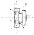
以下に本発明の実施形態を図面を参照して説明する。図1、図2は第1実施形態のワイヤレスヘッドホンを示す側面断面図及び上面断面図である。ワイヤレスヘッドホン10はインナイヤー型に構成され、ハウジング11で覆われた一端にスピーカ12(音声出力部)が露出して配される。ハウジング11内には電池14及び基板13が設けられる。 Embodiments of the present invention will be described below with reference to the drawings. 1 and 2 are a side sectional view and a top sectional view showing a wireless headphone according to a first embodiment. The
基板13上には受光部15、16及び信号処理回路17が実装される。受光部15、16は光信号から成る音声信号を受信して電気信号に変換する光電変換素子から成り、先端にレンズ等の集光手段19が設けられている。集光手段19を含む受光部15、16の光軸Aは平行に配され、受光部15、16が上下に並設されている。受光部15、16の受光面(不図示)は光軸Aに垂直で互いに相反する向きに配される。 On the
ハウジング11には光を透過する透光部18が設けられる。透光部18は受光部15、16の光軸A上に配され、音声信号が透過して受光部15、16で受光可能になっている。透光部18によって集光手段19を形成してもよい。 The
図3は信号処理回路17のブロック図を示している。信号処理回路17は復調部31、32、判定部33、制御部34及び増幅部35を有している。復調部31、32は受光部15、16から出力される電気信号を音声多重信号に復調する。判定部33は復調部31、32で復調された音声多重信号のS/N比を比較してS/N比の大小を判定する。制御部34は判定部33の判定結果に応じて音声多重信号から右音声または左音声の音声信号を出力する。増幅部35は制御部34から出力された音声信号を増幅して出力する。 FIG. 3 shows a block diagram of the
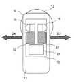
図4は一対のワイヤレスヘッドホン10を両耳にそれぞれ装着した状態を示す上面図である。右耳Rに装着されたワイヤレスヘッドホン10は受光部15の受光面(不図示)が前方に向けて配され、受光部16の受光面(不図示)が後方に向けて配される。左耳Lに装着されたワイヤレスヘッドホン10は受光部16の受光面が前方に向けて配され、受光部15の受光面が後方に向けて配される。 FIG. 4 is a top view showing a state in which a pair of
音楽再生装置20等は右音声の信号と左音声の信号とを多重化した赤外線等の光信号から成る音声信号Pを送信する。受光部15、16は音声信号Pをそれぞれ受光して電気信号に変換して出力する。このとき、受光部15、16は相反する向きに配されるため、右耳Rのワイヤレスヘッドホン10は受光部15の受光量が受光部16の受光量よりも多くなる。このため、受光部15の受信信号のS/N比が受光部16の受信信号のS/N比よりも高くなる。判定部33によって受光部15の受信信号のS/N比が高いと判定されると、制御部34は右耳Rに装着されていると判断して右音声を出力する。 The
同様に、左耳Lのワイヤレスヘッドホン10は受光部16の受光量が受光部15の受光量よりも多くなる。このため、受光部16の受信信号のS/N比が受光部15の受信信号のS/N比よりも高くなる。判定部33によって受光部16の受信信号のS/N比が高いと判定されると、制御部34は左耳Lに装着されていると判断して左音声を出力する。 Similarly, in the
本実施形態によると、相反する向きに配される受光部15、16を有し、受光部15、16の受信信号のS/N比の比較結果に基づいてスピーカ12から右音声と左音声とを切り替えて出力するので、使用者の操作を必要とせずに右音声と左音声を両耳に正確に伝えることができる。 According to the present embodiment, the
尚、受光部15、16は向きが180゜異なるように配置されていなくてもよい。即ち、耳に装着した際に受光部15、16の一方の受光面が前方を向き、他方の受光面が後方を向くように異なる向きに配置されていればよい。 The
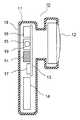
次に、図5は第2実施形態のワイヤレスヘッドホンを示す上面断面図である。説明の便宜上、前述の図1〜図4に示す第1実施形態と同様の部分には同一の符号を付している。本実施形態は第1実施形態に対して受光部15、16の配置が異なっている。その他の部分は第1実施形態と同様である。 Next, FIG. 5 is a top cross-sectional view showing the wireless headphones of the second embodiment. For convenience of explanation, the same reference numerals are given to the same parts as those in the first embodiment shown in FIGS. In the present embodiment, the arrangement of the
受光部15、16は光軸Aが同一直線上に配され、光軸Aに垂直でスピーカ12の中心を通る垂直面Vに対して面対称に配置されている。受光部15、16の光軸Aが前後に延びる一直線上に配されるので、受光部15、16が互いに相反する方向に向いて受信信号のS/N比の差を大きくすることができる。従って、ワイヤレスヘッドホン10の装着された側を正確に判別することができる。 The
加えて、左耳Lの受光部15と右耳Rの受光部16が耳に対して同じ位置に配置され、左耳Lの受光部16と右耳Rの受光部15が耳に対して同じ位置に配置される。これにより、左右で同じように音声信号Pを受信することができ、ワイヤレスヘッドホン10が左右のどちら側に装着されているかを略同じ受信条件で判別することができる。従って、判別結果が左右で矛盾することを低減できる。更に、ワイヤレスヘッドホン10を上下方向に小型化することができる。 In addition, the
次に、図6は第3実施形態のワイヤレスヘッドホンの信号処理部の構成を示すブロック図である。説明の便宜上、前述の図1〜図4に示す第1実施形態と同様の部分には同一の符号を付している。本実施形態は第1実施形態に対して信号処理部17の構成が異なっている。その他の部分は第1実施形態と同様である。 Next, FIG. 6 is a block diagram showing the configuration of the signal processing unit of the wireless headphones of the third embodiment. For convenience of explanation, the same reference numerals are given to the same parts as those in the first embodiment shown in FIGS. This embodiment is different from the first embodiment in the configuration of the
本実施形態の信号処理部17は判定部33と制御部34との間に補完部52が設けられている。補完部52は受光部15、16の受信信号を互いに比較して、欠損した情報を補完した信号を出力する。 In the
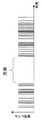
図7〜図9は補完部52による信号補完を説明する図である。図7、図8はそれぞれ受光部15、16の出力信号の例を示している。図9は補完部52の出力信号の例を示している。これらの図において、縦軸は信号レベルを示し、横軸は時間を示している。受光部15、16の受信信号は光電変換して出力され、判定部33によってS/N比が比較される。この例の場合は受光部15の信号レベルが大きくS/N比が大きいため、右耳Rに装着されていると判定される。 7 to 9 are diagrams for explaining signal complementation by the
次に、補完部52は受光部15、16の信号レベルを比較し、受光部15の出力信号に欠損があるか否かを判別する。この例の場合は図7、図8の比較によって受光部15の出力信号に欠損があると判別されるため、受光部16の出力信号によって欠損部分の信号が補完される。この時、受光部16の出力信号が受光部15と同程度まで信号レベルを増幅して補完される。そして、図9に示すように、欠損のない信号が補完部52から出力される。尚、受光部15の出力信号に欠損がないと判断した場合はそのまま補完部52から出力される。 Next, the complementing
本実施形態によると、受光部15、16で受信した一方の受信信号によって他方の受信信号を補完したので、音声の欠損を低減してワイヤレスヘッドホン10の品質を向上することができる。尚、第2実施形態のワイヤレスヘッドホン10の信号処理部17を本実施形態と同様に構成してもよい。 According to the present embodiment, since one received signal received by the
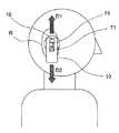
次に、図10は第4実施形態のワイヤレスヘッドホンを示す側面断面図である。説明の便宜上、前述の図1〜図4に示す第1実施形態と同様の部分には同一の符号を付している。本実施形態は第1実施形態に加えて、ワイヤレスヘッドホン10の装着時の姿勢を検知する姿勢検知センサ71を備えている。その他の部分は第1実施形態と同様である。 Next, FIG. 10 is a side sectional view showing the wireless headphones of the fourth embodiment. For convenience of explanation, the same reference numerals are given to the same parts as those in the first embodiment shown in FIGS. In addition to the first embodiment, the present embodiment includes an
姿勢検知センサ71は例えば内部に受光素子と発光素子と球体とを備え、球体の位置により受光が遮られる構造のものや、加速度センサにより構成される。判定部33(図3参照)は受光部15、16の受信信号のS/N比及び姿勢検知センサ71の検知結果に基づいてワイヤレスヘッドホン10の装着されている側を判別する。 For example, the
図11はワイヤレスヘッドホン10を右耳Rに装着した状態を側方から見た図である。姿勢検知センサ71から受光部16に向かう方向をD1とし、受光部16から姿勢検知センサ71に向かう方向をD2とする。判定部33は受信信号のS/N比が受光部16よりも受光部15の方が大きい場合には、方向D2が下向きの時に右耳Rに装着されたと判定して方向D1が下向きの時に左耳Lに装着されたと判定する。また、受信信号のS/N比が受光部15よりも受光部16の方が大きい場合には、方向D2が下向きの時に左耳Lに装着されたと判定して方向D1が下向きの時に右耳Rに装着されたと判定する。 FIG. 11 is a side view of the state in which the
従って、ワイヤレスヘッドホン10を上下反対に装着してもワイヤレスヘッドホン10の装着された側を正確に判別することができる。尚、第2、第3実施形態のワイヤレスヘッドホン10に姿勢検知センサ71を設けてもよい。 Therefore, even if the
次に、図12は第5実施形態のワイヤレスヘッドホンを示す正面断面図である。説明の便宜上、前述の図5に示す第2実施形態と同様の部分には同一の符号を付している。本実施形態は第2実施形態に加えて、受光部15、16の受光面前方の遮蔽物をそれぞれ検知する遮蔽物検知センサ91、92を備えている。その他の部分は第2実施形態と同様である。 Next, FIG. 12 is a front sectional view showing a wireless headphone according to a fifth embodiment. For convenience of explanation, the same reference numerals are given to the same parts as those of the second embodiment shown in FIG. In addition to the second embodiment, the present embodiment includes shielding
遮蔽物検知センサ91、92は、例えば光学三角測量方式の測距センサあるいは超音波方式のセンサなどにより構成される。これにより、遮蔽物の出射光や反射音を検知して受光面の前方(D3方向またはD4方向)数mm〜数十cmの遮蔽物の有無を判別する。判定部33(図3参照)は受光部15、16の受信信号のS/N比及び遮蔽物検知センサ91、92の検知結果に基づいてワイヤレスヘッドホン10の装着されている側を判別する。 The shielding
図13はワイヤレスヘッドホン10を右耳Rに装着した状態を側方から見た図である。ワイヤレスヘッドホン10を右耳Rに装着した場合は、遮蔽物検知センサ92によって右耳Rの耳たぶRaがD4方向の遮蔽物として検知される。この時、遮蔽物検知センサ91にはD3方向の遮蔽物が検知されない。同様に、ワイヤレスヘッドホン10を左耳Lに装着した場合は、遮蔽物検知センサ91によって左耳Lの耳たぶがD3方向の遮蔽物として検知される。この時、遮蔽物検知センサ92にはD4方向の遮蔽物が検知されない。 FIG. 13 is a side view of the state in which the
判定部33は受光部15、16の受信信号のS/N比の大小によってワイヤレスヘッドホン10が装着されている側を判定する。この時、音楽再生装置20(図4参照)等から送信される光信号の方向に対して真横を向いている時等に、受信信号のS/N比が受光部15、16間で所定量以下の差になって大小の判別が困難になる場合がある。また、所定時間内に所定回数以上に頻繁にS/N比の大小関係が反転する場合もある。 The
このような場合には、遮蔽物検知センサ91、92の検知結果に基づいてワイヤレスヘッドホン10が装着されている側を判定する。即ち、遮蔽物検知センサ92により遮蔽物を検知した場合は右耳Rに装着されていると判定する。また、遮蔽物検知センサ91により遮蔽物を検知した場合は左耳Lに装着されていると判定する。 In such a case, the side to which the
本実施形態によると、受光部15、16の受光面前方の遮蔽物をそれぞれ検知する遮蔽物検知センサ91、92を設けたので、音楽再生装置20等から送信される光信号の方向に対して真横を向いた場合等であっても耳たぶを検知してワイヤレスヘッドホン10の装着された側を正確に判別することができる。また、ワイヤレスヘッドホン10が装着されているか否かを判断し、自動で電源をON/OFFすることで省電力化を図ることができる。尚、第1、第3、第4実施形態のワイヤレスヘッドホン10に姿勢検知センサ71を設けてもよい。 According to the present embodiment, since the shielding
次に、図14は第6実施形態のワイヤレスヘッドホンを示す正面図である。説明の便宜上、前述の図1〜図4に示す第1実施形態と同様の部分には同一の符号を付している。本実施形態は第1実施形態に加えて、受光部15、16に面した透光部18をそれぞれ遮蔽する可動のシャッター111、112を備えている。その他の部分は第1実施形態と同様である。 Next, FIG. 14 is a front view showing the wireless headphones of the sixth embodiment. For convenience of explanation, the same reference numerals are given to the same parts as those in the first embodiment shown in FIGS. In addition to the first embodiment, the present embodiment includes
シャッター111、112は遮光性の材料から成り、使用者の操作によって上下に可動して透光部18を塞ぐ位置と開放する位置との間を移動する。これにより、使用者は受光部15、16の受光面を塞いで光信号から成る音声信号を到達させないようにすることができる。 The
本実施形態によると、音楽再生装置20(図4参照)等から送信される光信号の方向に対して真横を向いて、受信信号のS/N比が受光部15、16間で所定量以下の差になる場合や、頻繁にS/N比の大小関係が反転する場合に、使用者に対して後方のシャッターを閉じてS/N比の大小を正確に検知することができる。また、音楽再生装置20等に対して背を向けている場合に使用者に対して後方のシャッターを閉じて左右の誤検知を防止することができる。尚、第2〜第5実施形態のワイヤレスヘッドホン10にシャッター111、112を設けてもよい。 According to the present embodiment, the S / N ratio of the received signal is equal to or less than a predetermined amount between the
次に、図15は第7実施形態のワイヤレスヘッドホンを示す正面図である。また、図16はワイヤレスヘッドホンの信号処理部を示すブロック図である。説明の便宜上、前述の図1〜図4に示す第1実施形態と同様の部分には同一の符号を付している。本実施形態は第1実施形態に加えて、通信部121を備えている。その他の部分は第1実施形態と同様である。 Next, FIG. 15 is a front view showing the wireless headphones of the seventh embodiment. FIG. 16 is a block diagram showing a signal processing unit of the wireless headphones. For convenience of explanation, the same reference numerals are given to the same parts as those in the first embodiment shown in FIGS. This embodiment includes a
前述の図4に示すように、ワイヤレスヘッドホン10は左右1対設けられる。通信部121は送信部122及び受信部123を有している。ワイヤレスヘッドホン10の制御部34は受光部15、16の受信信号の信号レベルの大きい方を送信部122に送り、送信部122から送信する。受信部123は他方のワイヤレスヘッドホン10の送信部121から送信された信号を受信する。通信部121は無線によって送受信しているが、有線によって送受信を行ってもよい。 As shown in FIG. 4 described above, a pair of left and
制御部34は受光部15、16の受信信号の信号レベルと、受信部123で受信した信号の信号レベルとを比較し、受光部15、16の受信信号に欠損があるか否かを判別する。前述の図7〜図9と同様に、受光部15、16の受信信号に欠損があると判別されると、受信部123で受信した信号によって欠損部分の信号が補完される。そして、欠損のない信号が制御部34から出力される。尚、受光部15、16の受信信号に欠損がないと判断した場合はそのまま制御部34から出力される。 The
本実施形態によると、両耳に装着された一対のワイヤレスヘッドホン10が受光部15、16で受信した信号を送信部122から送信し、他方の送信部122から送信されて受信部123で受信した信号によって受光部15、16の受信信号を補完したので、音声の欠損を低減してワイヤレスヘッドホン10の品質をより向上することができる。尚、第2〜第6実施形態のワイヤレスヘッドホン10に通信部121を設けてもよい。 According to the present embodiment, the pair of
第1〜第7実施形態において、受光部15、16の受信信号のS/N比を比較してワイヤレスヘッドホン10の装着された側を検知しているが、受光部15、16の受信信号の信号レベルを比較してワイヤレスヘッドホン10の装着された側を検知してもよい。 In the first to seventh embodiments, the S / N ratio of the reception signals of the
本発明によると、光信号から成る音声信号を受信して音声を出力するワイヤレスヘッドホンに利用することができる。 ADVANTAGE OF THE INVENTION According to this invention, it can utilize for the wireless headphones which receive the audio | voice signal which consists of an optical signal, and output an audio | voice.
10 ワイヤレスヘッドホン
11 ハウジング
12 スピーカユニット
13 基板
14 電池
15、16 受光素子
17 信号処理回路
18 透光部
19 集光手段
20 音楽再生装置
31、32 復調部
33 判定部
34 制御部
35 増幅部
52 補完部
71 姿勢検知センサ
91、92 遮蔽物検知センサ
111、112 シャッター
121 通信部
122 送信部
123 受信部DESCRIPTION OF
Claims (7)
Translated fromJapanesePriority Applications (3)
| Application Number | Priority Date | Filing Date | Title |
|---|---|---|---|
| JP2006282626AJP2008103827A (en) | 2006-10-17 | 2006-10-17 | Wireless headphones |
| US11/867,056US20080089539A1 (en) | 2006-10-17 | 2007-10-04 | Wireless headphones |
| CNA2007101808576ACN101166372A (en) | 2006-10-17 | 2007-10-17 | Wireless headphones |
Applications Claiming Priority (1)
| Application Number | Priority Date | Filing Date | Title |
|---|---|---|---|
| JP2006282626AJP2008103827A (en) | 2006-10-17 | 2006-10-17 | Wireless headphones |
Publications (1)
| Publication Number | Publication Date |
|---|---|
| JP2008103827Atrue JP2008103827A (en) | 2008-05-01 |
Family
ID=39303143
Family Applications (1)
| Application Number | Title | Priority Date | Filing Date |
|---|---|---|---|
| JP2006282626APendingJP2008103827A (en) | 2006-10-17 | 2006-10-17 | Wireless headphones |
Country Status (3)
| Country | Link |
|---|---|
| US (1) | US20080089539A1 (en) |
| JP (1) | JP2008103827A (en) |
| CN (1) | CN101166372A (en) |
Cited By (1)
| Publication number | Priority date | Publication date | Assignee | Title |
|---|---|---|---|---|
| JP2016500233A (en)* | 2012-11-19 | 2016-01-07 | ゼットティーイー コーポレーションZte Corporation | Electronic device control method using optical sensor earphone and optical sensor earphone |
Families Citing this family (26)
| Publication number | Priority date | Publication date | Assignee | Title |
|---|---|---|---|---|
| EP2031418B1 (en)* | 2007-08-27 | 2017-11-01 | Harman Becker Automotive Systems GmbH | Tracking system using RFID (radio frequency identification) technology |
| US8788002B2 (en)* | 2009-02-25 | 2014-07-22 | Valencell, Inc. | Light-guiding devices and monitoring devices incorporating same |
| EP3127476A1 (en) | 2009-02-25 | 2017-02-08 | Valencell, Inc. | Light-guiding devices and monitoring devices incorporating same |
| US8913771B2 (en)* | 2009-03-04 | 2014-12-16 | Apple Inc. | Portable electronic device having a water exposure indicator label |
| EP2288178B1 (en)* | 2009-08-17 | 2012-06-06 | Nxp B.V. | A device for and a method of processing audio data |
| KR20120053587A (en)* | 2010-11-18 | 2012-05-29 | 삼성전자주식회사 | Display apparatus and sound control method of the same |
| US9769556B2 (en) | 2012-02-22 | 2017-09-19 | Snik Llc | Magnetic earphones holder including receiving external ambient audio and transmitting to the earphones |
| US10524038B2 (en) | 2012-02-22 | 2019-12-31 | Snik Llc | Magnetic earphones holder |
| US9113246B2 (en)* | 2012-09-20 | 2015-08-18 | International Business Machines Corporation | Automated left-right headphone earpiece identifier |
| CN104113794A (en)* | 2013-04-22 | 2014-10-22 | 联想(北京)有限公司 | Information processing method, information processing system and headset |
| CN104125522A (en)* | 2014-07-18 | 2014-10-29 | 北京智谷睿拓技术服务有限公司 | Sound track configuration method and device and user device |
| US9961446B2 (en) | 2014-08-27 | 2018-05-01 | Yulong Computer Telecommunication Scientific (Shenzhen) Co., Ltd. | Earphone recognition method and apparatus, earphone control method and apparatus, and earphone |
| CN106412735A (en)* | 2015-07-29 | 2017-02-15 | 联想移动通信科技有限公司 | Method and device for adjusting headset data, headset and terminal |
| CN105681946A (en)* | 2015-12-31 | 2016-06-15 | 东莞酷派软件技术有限公司 | Headphone, headphone channel control method and terminal |
| US10225640B2 (en) | 2016-04-19 | 2019-03-05 | Snik Llc | Device and system for and method of transmitting audio to a user |
| US10951968B2 (en) | 2016-04-19 | 2021-03-16 | Snik Llc | Magnetic earphones holder |
| US10631074B2 (en) | 2016-04-19 | 2020-04-21 | Snik Llc | Magnetic earphones holder |
| US10455306B2 (en)* | 2016-04-19 | 2019-10-22 | Snik Llc | Magnetic earphones holder |
| US11272281B2 (en) | 2016-04-19 | 2022-03-08 | Snik Llc | Magnetic earphones holder |
| TWI727168B (en)* | 2018-05-16 | 2021-05-11 | 群光電子股份有限公司 | Symmetrical earphone device |
| US11105636B2 (en)* | 2019-04-17 | 2021-08-31 | Google Llc | Radio enhanced augmented reality and virtual reality with truly wireless earbuds |
| US11234078B1 (en)* | 2019-06-27 | 2022-01-25 | Apple Inc. | Optical audio transmission from source device to wireless earphones |
| WO2021015761A1 (en)* | 2019-07-24 | 2021-01-28 | Hewlett-Packard Development Company L.P. | Audio headset position detection |
| CN113411702B (en)* | 2020-03-16 | 2024-05-14 | 维沃移动通信有限公司 | Sound channel configuration method and electronic equipment |
| CN113132021B (en)* | 2021-03-15 | 2022-06-28 | 南京敏智达科技有限公司 | Underwater audio-optical communication system and method with direction sensing auxiliary function |
| CN115278470A (en)* | 2021-04-30 | 2022-11-01 | 华为技术有限公司 | Method for calibrating left and right ear of earphone and earphone |
Family Cites Families (3)
| Publication number | Priority date | Publication date | Assignee | Title |
|---|---|---|---|---|
| DE3635950A1 (en)* | 1985-10-22 | 1987-04-23 | Toshiba Kawasaki Kk | SYSTEM FOR EXPOSING A X-RAY FILM WITH X-RAY RAYS TO Adequate DENSITY |
| JP2007506334A (en)* | 2003-09-22 | 2007-03-15 | コニンクリユケ フィリップス エレクトロニクス エヌ.ブイ. | Electrical device, system, and method |
| US7522065B2 (en)* | 2004-10-15 | 2009-04-21 | Microsoft Corporation | Method and apparatus for proximity sensing in a portable electronic device |
- 2006
- 2006-10-17JPJP2006282626Apatent/JP2008103827A/enactivePending
- 2007
- 2007-10-04USUS11/867,056patent/US20080089539A1/ennot_activeAbandoned
- 2007-10-17CNCNA2007101808576Apatent/CN101166372A/enactivePending
Cited By (1)
| Publication number | Priority date | Publication date | Assignee | Title |
|---|---|---|---|---|
| JP2016500233A (en)* | 2012-11-19 | 2016-01-07 | ゼットティーイー コーポレーションZte Corporation | Electronic device control method using optical sensor earphone and optical sensor earphone |
Also Published As
| Publication number | Publication date |
|---|---|
| US20080089539A1 (en) | 2008-04-17 |
| CN101166372A (en) | 2008-04-23 |
Similar Documents
| Publication | Publication Date | Title |
|---|---|---|
| JP2008103827A (en) | Wireless headphones | |
| US20160198250A1 (en) | Headphone device with controlling function | |
| KR100872845B1 (en) | Headset with custom audio service and custom audio service method using it | |
| KR101820730B1 (en) | Detecting System For connecting of Earphone And Electric Device supporting the same | |
| US20020094789A1 (en) | Portable radio terminal device | |
| EP3467858B1 (en) | Photoelectric sensor | |
| US20160014539A1 (en) | Earphone and sound channel control method thereof | |
| EP3627854B1 (en) | Method for operating a hearing system and hearing system comprising two hearing devices | |
| KR20210109526A (en) | Specific sound detector and method, and program | |
| US11937059B2 (en) | Composite headphone | |
| CN108055605B (en) | Neck wire Bluetooth earphone and application method thereof | |
| WO2022233193A1 (en) | Detection method for earphone, and earphones and storage medium | |
| US20140192992A1 (en) | System for Fitting Audio Signals for In-Use Ear | |
| CN213586218U (en) | Headphones, Headphone Components, Electronic Systems, Wearing Detection Components and Wearable Devices | |
| CN112367589B (en) | Headphones, headphone components, electronic systems, wearing detection components and wearable devices | |
| JPS61234699A (en) | hearing aid | |
| EP1182809A3 (en) | Safety shutdown system for a WDM fiber optic communications network | |
| EP2577995A2 (en) | Hearing device with a light guide and method for manufacturing such a hearing device | |
| US9497532B2 (en) | Headphone device with controlling function | |
| CN211063759U (en) | Bluetooth headset capable of measuring body temperature and transmitting measurement result to mobile phone | |
| US20180139530A1 (en) | Portable Binaural Recording, Processing and Playback Device | |
| CN214901306U (en) | hearing aid | |
| WO2022233192A1 (en) | Detection method for wireless in-ear earphones, and earphones and storage medium | |
| WO2018191847A1 (en) | Head-mountable display device and method for power conditioning sensor thereof | |
| CN113490093A (en) | TWS earphone |
Legal Events
| Date | Code | Title | Description |
|---|---|---|---|
| A977 | Report on retrieval | Free format text:JAPANESE INTERMEDIATE CODE: A971007 Effective date:20081024 | |
| A131 | Notification of reasons for refusal | Free format text:JAPANESE INTERMEDIATE CODE: A131 Effective date:20081118 | |
| A02 | Decision of refusal | Free format text:JAPANESE INTERMEDIATE CODE: A02 Effective date:20090508 |