JP2008098858A - Vehicle periphery monitoring device - Google Patents
Vehicle periphery monitoring deviceDownload PDFInfo
- Publication number
- JP2008098858A JP2008098858AJP2006276806AJP2006276806AJP2008098858AJP 2008098858 AJP2008098858 AJP 2008098858AJP 2006276806 AJP2006276806 AJP 2006276806AJP 2006276806 AJP2006276806 AJP 2006276806AJP 2008098858 AJP2008098858 AJP 2008098858A
- Authority
- JP
- Japan
- Prior art keywords
- vehicle
- image
- detection
- display
- range
- Prior art date
- Legal status (The legal status is an assumption and is not a legal conclusion. Google has not performed a legal analysis and makes no representation as to the accuracy of the status listed.)
- Pending
Links
Images


Landscapes
- Fittings On The Vehicle Exterior For Carrying Loads, And Devices For Holding Or Mounting Articles (AREA)
- Image Processing (AREA)
- Closed-Circuit Television Systems (AREA)
- Traffic Control Systems (AREA)
- Image Analysis (AREA)
Abstract
Translated fromJapaneseDescription
Translated fromJapanese本発明は、車両に搭載したカメラで車両の周辺を撮像し、車内に設けられたディスプレイに撮像した画像を表示することができる車両周辺監視装置に関する。 The present invention relates to a vehicle periphery monitoring apparatus that can capture the periphery of a vehicle with a camera mounted on the vehicle and display the captured image on a display provided in the vehicle.
従来、車両の前側、後側又は左右側にカメラを搭載して車両の外界を撮像し、撮像により取得した画像を車内に設けられたディスプレイに表示することによって、運転者へ種々の情報を提供する車両周辺監視装置が実用化されている。例えば、車両の運転席から死角となる部分を撮像するカメラを搭載することによって、運転者が直接に目視できない部分をディスプレイに表示することができるため、事故を未然に防ぐことが可能となる。 Conventionally, a camera is mounted on the front side, rear side, or left and right sides of a vehicle to capture the outside world of the vehicle, and various images are provided to the driver by displaying an image acquired by the imaging on a display provided in the vehicle. A vehicle periphery monitoring device has been put into practical use. For example, by installing a camera that captures a blind spot from the driver's seat of the vehicle, a portion that cannot be directly seen by the driver can be displayed on the display, so that an accident can be prevented.
特許文献1においては、車両の後方を撮像するカメラを搭載し、カメラにより撮像して取得した画像を基に、車両を後退させる前に後退進路上の障害物を発見して運転者に報知することによって、車両後退時の後方安全確認を支援する後退支援装置が提案されている。この後退支援装置では、車速センサにより停車を認識しているときにシフトレバーが「P」又は「N」に入れられたことを検知すると、カメラにより車両後方の基準画像を撮像する。その後、運転席のドアの開閉を検知する毎に基準画像を更新する。シフトレバーが「R」に入れられた場合、カメラにより比較画像を逐次撮像し、基準画像と比較画像とを比較する画像処理を行って車両後方の障害物を検出する。障害物を検出した場合には、モニタの画像中に障害物を囲む矩形を表示すると共に、スピーカから音声警告を発するようにしてある。 In
車内に設けられたディスプレイは、上述のように車両の周辺を撮像して取得した画像を表示するだけでなく、例えばカーナビゲーション装置が現在位置を通知するための地図を表示する場合に用いられ、また、車両に搭載されたチューナにより受信したテレビ番組を表示する場合に用いられるなど、多種の目的に利用されることが多い。よって、ディスプレイに表示する画像を切り替える必要があるが、従来の場合には、運転者がスイッチ又はボタン等を操作して直接的に画像を切り替えるか、又は車速及びシフトレバーの状態等の車両情報を基に自動的に画像を切り替えるかしていた。
ディスプレイに表示する画像の切り替えを運転者の操作により行う場合、切り替えの操作が運転者にとって煩わしいため、車両の周辺に歩行者又は障害物等が存在するなど画像の表示が必要なときに、必ずしも運転者が操作を行って車両周辺の画像を表示させるとは限らず、車両周辺の歩行者又は障害物等を見落とす虞がある。また、画像の切り替えを車両情報を基に行う場合、例えばシフトレバーが「R」のときには後方の画像を表示し、シフトレバーが「D」であり且つ車速が低速のときには前方の画像を表示するなどの場合、車速などの車両情報は検知精度が高くないため誤切替が発生する可能性があると共に、車両周辺に歩行者又は障害物等が存在せず画像の表示が必要ないときであっても画像がディスプレイに表示され、カーナビゲーション装置の地図表示又はテレビ番組の表示等を妨げる虞がある。 When switching the image displayed on the display by the driver's operation, since the switching operation is troublesome for the driver, it is not always necessary to display an image such as there are pedestrians or obstacles around the vehicle. The driver does not always display an image around the vehicle by operating, and there is a possibility that a pedestrian or an obstacle around the vehicle may be overlooked. Also, when switching images based on vehicle information, for example, the rear image is displayed when the shift lever is “R”, and the front image is displayed when the shift lever is “D” and the vehicle speed is low. In the case of vehicle information such as vehicle speed, there is a possibility that erroneous switching may occur because the detection accuracy is not high, and there is no pedestrian or obstacle around the vehicle and image display is not necessary However, the image is displayed on the display, which may hinder the map display of the car navigation device or the display of the television program.
この問題を解決するために、車両の周辺をカメラで撮像して取得した画像を基に、車両の周辺に歩行者又は障害物等が存在するか否かを判定する画像処理を行い、この結果に応じてディスプレイに表示する画像の切り替えを行う。このときの画像処理は、例えば、ある時刻t1の画像とその後の時刻t2の画像とを比較し、画像に変化が生じている場合には車両の周辺に歩行者又は障害物等が存在すると判定するなどの処理である。これにより、カーナビゲーション装置の地図表示又はテレビ番組の表示等を妨げることなく、必要なときにのみディスプレイに車両周辺の画像を表示することができる。 In order to solve this problem, image processing is performed to determine whether or not there are pedestrians or obstacles around the vehicle based on an image obtained by capturing the periphery of the vehicle with a camera. The image displayed on the display is switched in response to. In this image processing, for example, an image at a certain time t1 is compared with an image at a subsequent time t2, and if there is a change in the image, it is determined that there are pedestrians or obstacles around the vehicle. Process. Accordingly, an image around the vehicle can be displayed on the display only when necessary without hindering the map display of the car navigation device or the display of the television program.
しかしながら、車両に搭載されるカメラは魚眼レンズ又は広角レンズ等のレンズを用いて撮像を行う場合が多く、車両の周辺を広範囲に亘って撮像できるようにしてあるが、特に撮像して取得した画像の端部分では像が歪んだ低解像度の画像となるため、上述のような画像処理を行って表示する画像の切り替えを行う場合に、精度のよい画像処理を行うことができない可能性がある。また、異なる時刻で取得した2つの画像を比較する場合に、例えば周囲の明るさが大きく変化するなど、周囲の環境の変化によって、2つの画像が全体的に異なる画像となる可能性があり、画像処理を正確に行うことができない虞がある。 However, a camera mounted on a vehicle often performs imaging using a lens such as a fish-eye lens or a wide-angle lens, so that the periphery of the vehicle can be imaged over a wide range. Since the edge portion is a low-resolution image in which the image is distorted, there is a possibility that accurate image processing cannot be performed when the image to be displayed is switched by performing the above-described image processing. Also, when comparing two images acquired at different times, the two images may be entirely different due to changes in the surrounding environment, for example, the brightness of the surroundings changes significantly. There is a possibility that image processing cannot be performed accurately.
本発明は、斯かる事情に鑑みてなされたものであって、その目的とするところは、車両に搭載したカメラなどの撮像手段が異なる時点で撮像した複数の画像を基に画像の変化を検出し、検出結果に応じてディスプレイなどの表示手段に撮像した画像を表示させる場合に、検出を行う画像の範囲を車両の前進方向又は後退方向について車両から所定の範囲までに制限する構成とすることにより、魚眼レンズ又は広角レンズ等のレンズを用いて撮像を行う場合であっても、検出を高精度に行うことができる車両周辺監視装置を提供することにある。 The present invention has been made in view of such circumstances, and an object of the present invention is to detect an image change based on a plurality of images captured at different points in time by an imaging unit such as a camera mounted on a vehicle. When the captured image is displayed on a display means such as a display according to the detection result, the range of the image to be detected is limited to a predetermined range from the vehicle in the forward or backward direction of the vehicle. Accordingly, it is an object of the present invention to provide a vehicle periphery monitoring device capable of performing detection with high accuracy even when imaging is performed using a lens such as a fisheye lens or a wide-angle lens.
また本発明の他の目的とするところは、車両の前方及び後方を撮像することを可能とし、複数の画像を基に変化の検出を行う場合に、検出を行う画像の範囲を車両の前進方向及び後退方向の両方向について車両から所定の距離範囲までに制限する構成とすることにより、車両の駐車又は車庫入れ等を行うために車両の前進及び後退を繰り返し行うときに、車両の前後に存在する歩行者又は障害物等を画像の変化から高精度に検出することができる車両周辺監視装置を提供することにある。 Another object of the present invention is to make it possible to image the front and rear of a vehicle, and when detecting changes based on a plurality of images, the range of images to be detected is determined in the forward direction of the vehicle. In addition, when the vehicle is repeatedly moved forward and backward in order to park the vehicle or enter the garage, the vehicle is present in front of and behind the vehicle by restricting the vehicle to a predetermined distance range from the vehicle in both the reverse direction and the reverse direction. An object of the present invention is to provide a vehicle periphery monitoring device capable of detecting a pedestrian or an obstacle with high accuracy from a change in an image.
また本発明の他の目的とするところは、車両のハンドルの舵角を検知し、ハンドルの舵角に応じて制限する画像の範囲を調整する構成とすることにより、車両が進行する可能性が高い範囲に存在する歩行者又は障害物等を画像の変化から高精度に検出することができる車両周辺監視装置を提供することにある。 Another object of the present invention is to detect the steering angle of the steering wheel of the vehicle and adjust the range of the image to be limited according to the steering angle of the steering wheel, so that the vehicle may travel. An object of the present invention is to provide a vehicle periphery monitoring device that can detect a pedestrian or an obstacle existing in a high range with high accuracy from a change in an image.
また本発明の他の目的とするところは、各画素の輝度が所定輝度内に収まる範囲に、制限する画像の範囲を調整する構成とすることにより、輝度が高すぎて又は低すぎて検出を精度よく行うことができない部分を検出の範囲外とすることができる車両周辺監視装置を提供することにある。 Another object of the present invention is to adjust the range of the image to be limited to a range in which the luminance of each pixel is within the predetermined luminance, thereby detecting the luminance too high or too low. An object of the present invention is to provide a vehicle periphery monitoring device that can make a portion that cannot be accurately performed out of the detection range.
また本発明の他の目的とするところは、車両の周囲の環境が雨天であるか否かを検知し、雨天の場合には、撮像手段により撮像された画像を基に変化を検出して表示手段に画像を表示させる処理を停止する構成とすることにより、変化の検出を行うことが難しい雨天時に、誤検出による画像の誤表示を行うことを防止できる車両周辺監視装置を提供することにある。 Another object of the present invention is to detect whether or not the environment surrounding the vehicle is rainy, and in the case of rain, the change is detected and displayed based on the image captured by the imaging means. An object of the present invention is to provide a vehicle periphery monitoring device capable of preventing erroneous display of an image due to erroneous detection when it is difficult to detect a change, by stopping the process of displaying an image on the means. .
また本発明の他の目的とするところは、車両の周囲の環境が夜間であるか否かを検知し、夜間の場合には、撮像手段により撮像された画像を基に変化を検出して表示手段に画像を表示させる処理を停止する構成とすることにより、変化の検出を行うことが難しい夜間に、誤検出による画像の誤表示を行うことを防止できる車両周辺監視装置を提供することにある。 Another object of the present invention is to detect whether or not the environment around the vehicle is nighttime, and in the case of nighttime, the change is detected and displayed based on the image taken by the imaging means. An object of the present invention is to provide a vehicle periphery monitoring device capable of preventing erroneous display of an image due to erroneous detection at night when it is difficult to detect change by adopting a configuration in which processing for displaying an image on a means is stopped. .
また本発明の他の目的とするところは、撮像手段により撮像された画像を基に変化を検出して表示手段に画像を表示させる処理を停止している旨を運転者に報知する構成とすることにより、処理を停止していることを運転者に確実に認識させることができる車両周辺監視装置を提供することにある。 Another object of the present invention is to notify the driver that the process of detecting a change based on the image captured by the imaging unit and displaying the image on the display unit is stopped. Accordingly, an object of the present invention is to provide a vehicle periphery monitoring device that allows a driver to reliably recognize that processing is stopped.
また本発明の他の目的とするところは、撮像手段が撮像を行って画像を取得したときの撮像条件を取得し、変化を検出する複数の画像の撮像条件が同じであるか否かを判定し、同じでない場合には撮像条件の差異に応じて画像の補正を行う構成とすることにより、周囲の環境の変化によって撮像手段の撮像条件が変更された場合であっても、検出を高精度に行うことができる車両周辺監視装置を提供することにある。 Another object of the present invention is to acquire an imaging condition when the imaging unit captures an image to acquire an image, and determines whether or not the imaging conditions of a plurality of images for detecting a change are the same. If they are not the same, the image is corrected according to the difference in the imaging conditions, so that even when the imaging conditions of the imaging means are changed due to changes in the surrounding environment, the detection can be performed with high accuracy. An object of the present invention is to provide a vehicle periphery monitoring device that can be used in the future.
第1発明に係る車両周辺監視装置は、車両に搭載され、該車両の外界を撮像して画像を取得する撮像手段と、該撮像手段が撮像して取得した画像を表示する表示手段とを備える車両周辺監視装置において、前記撮像手段が異なる時点で撮像して取得した複数の画像を基に、画像の変化を検出する検出手段と、該検出手段が検出を行う画像の範囲を制限する制限手段と、前記検出手段の検出結果に応じて、前記撮像手段が撮像した画像を前記表示手段に表示させる処理を行う表示処理手段とを備え、前記制限手段は、前記車両の前進方向又は後退方向について前記車両から所定の範囲内に、検出を行う画像の範囲を制限するようにしてあることを特徴とする。 A vehicle periphery monitoring apparatus according to a first aspect of the present invention includes an imaging unit that is mounted on a vehicle and captures an image of the outside world of the vehicle to acquire an image, and a display unit that displays an image captured and acquired by the imaging unit. In the vehicle periphery monitoring apparatus, a detecting unit that detects a change in an image based on a plurality of images acquired by the imaging unit at different time points, and a limiting unit that limits a range of images that the detecting unit detects. And a display processing means for performing processing for causing the display means to display an image picked up by the image pickup means in accordance with a detection result of the detection means, wherein the restriction means is for a forward direction or a reverse direction of the vehicle. The range of the image to be detected is limited within a predetermined range from the vehicle.
本発明においては、撮像手段により車両の周辺の外界を撮像し、異なる時点で撮像して取得した複数の画像に生じた変化を検出し、検出結果に応じて表示手段による画像の表示を行う。変化の検出は、取得した画像の全体を対象として行うのではなく、車両の前進方向又は後退方向について車両から所定の範囲までに制限した範囲で行う。これにより、撮像手段が魚眼レンズ又は広角レンズ等のレンズを用いて撮像を行い、画像の端部分が低解像度となる場合であっても、この低解像度となる部分を検出の範囲外とすることができ、検出の精度低下を防止できる。なお、画像の端部分の低解像度となる部分は、車両から遠方の領域であるため、歩行者又は障害物等が存在する場合であっても、車両の走行に対する危険度は低いため、検出の範囲外として問題ない。 In the present invention, the outside world around the vehicle is picked up by the image pickup means, changes occurring in a plurality of images picked up and acquired at different time points are detected, and the image is displayed by the display means according to the detection result. The change detection is not performed on the entire acquired image but in a range limited to a predetermined range from the vehicle in the forward or backward direction of the vehicle. As a result, even when the imaging unit performs imaging using a lens such as a fish-eye lens or a wide-angle lens, and the end portion of the image has a low resolution, the low resolution portion may be outside the detection range. It is possible to prevent a decrease in detection accuracy. Note that the low-resolution part of the edge of the image is an area far from the vehicle, so even if there are pedestrians or obstacles, the risk of running the vehicle is low, There is no problem as out of range.
また、第2発明に係る車両周辺監視装置は、前記撮像手段が、前記車両の前方及び後方を撮像することが可能にしてあり、前記制限手段は、前記車両の前進方向及び後退方向の両方向について前記車両から所定の距離範囲内に、検出を行う画像の範囲を制限するようにしてあることを特徴とする。 In the vehicle periphery monitoring apparatus according to the second aspect of the present invention, the imaging unit can image the front and rear of the vehicle, and the limiting unit is configured to perform both the forward direction and the reverse direction of the vehicle. The range of the image to be detected is limited within a predetermined distance range from the vehicle.
本発明においては、例えば車両の前部及び後部にカメラを搭載するなどして、車両の前方及び後方の撮像を可能とする。変化の検出は、車両の前進方向及び後退方向の両方向について車両から所定の距離範囲までに制限した範囲で行う。例えば、車両の駐車又は車庫入れ等を行う場合には、車両の前進及び後退を短い時間で繰り返して行うことが多いが、運転者は車両の前後両方を繰り返して目視する必要があり、また、車両の操作が繁雑であるため、車両周辺の歩行者又は障害物等を見落とす虞がある。よって、車両の前進方向及び後退方向の両方向を検出の範囲とすることで、駐車又は車庫入れ等の運転を補助することができる。 In the present invention, for example, a camera is mounted on the front part and the rear part of the vehicle, thereby enabling imaging of the front and rear of the vehicle. The change is detected in a range limited to a predetermined distance range from the vehicle in both the forward direction and the reverse direction of the vehicle. For example, when performing parking or garage parking of a vehicle, the vehicle is often repeatedly moved forward and backward in a short time, but the driver needs to visually observe both the front and rear of the vehicle, Since the operation of the vehicle is complicated, there is a possibility that a pedestrian or an obstacle around the vehicle may be overlooked. Therefore, driving such as parking or garage entry can be assisted by setting both the forward direction and the reverse direction of the vehicle as the detection range.
また、第3発明に係る車両周辺監視装置は、前記車両のハンドルの舵角を検知する検知手段を備え、前記制限手段は、前記検知手段の検知結果に応じて、制限する画像の範囲を調整するようにしてあることを特徴とする。 According to a third aspect of the present invention, there is provided a vehicle periphery monitoring apparatus including a detecting unit that detects a steering angle of the steering wheel of the vehicle, and the limiting unit adjusts a range of an image to be limited according to a detection result of the detecting unit. It is made to do so.
本発明においては、車両のハンドルの舵角を検知し、ハンドルの舵角に応じて制限する画像の範囲を調整する。運転者がハンドルを操作することにより、車両の前進方向又は後退方向が変化するため、これに応じて検出を行う範囲を調整することによって、車両が前進又は後退した場合の経路上に存在する歩行者又は障害物等を検出することができる。 In the present invention, the steering angle of the steering wheel of the vehicle is detected, and the range of the image to be limited is adjusted according to the steering angle of the steering wheel. As the driver operates the steering wheel, the forward or backward direction of the vehicle changes. Therefore, by adjusting the detection range accordingly, walking that exists on the route when the vehicle moves forward or backward A person or an obstacle can be detected.
また、第4発明に係る車両周辺監視装置は、前記撮像手段が撮像して取得する画像は複数の画素からなり、前記制限手段は、各画素の輝度が所定輝度内に収まる範囲に、制限する画像の範囲を調整するようにしてあることを特徴とする。 In the vehicle periphery monitoring device according to the fourth aspect of the present invention, the image acquired by the imaging unit is made up of a plurality of pixels, and the limiting unit limits the luminance of each pixel within a predetermined luminance range. The image range is adjusted.
本発明においては、検出を行う画像の範囲を制限するときに、各画素の輝度が所定輝度内に収まる範囲に制限する画像の範囲を調整する。画像中の輝度が極端に高い部分、所謂白飛びの部分及び輝度が極端に低い部分、所謂黒つぶれの部分等では、画像中に生じた変化を精度よく検出することができないため、この部分を検出の範囲外とすることにより、検出精度の低下及び誤検出等を防止できる。 In the present invention, when the range of the image to be detected is limited, the range of the image that limits the luminance of each pixel within the predetermined luminance is adjusted. Changes that occur in the image cannot be detected with high precision in areas with extremely high brightness, so-called whiteout areas and areas with extremely low brightness, so-called blackout areas. By making it outside the detection range, it is possible to prevent a decrease in detection accuracy, erroneous detection, and the like.
また、第5発明に係る車両周辺監視装置は、前記車両の周囲の環境が雨天であるか否かを検知する検知手段を備え、前記表示処理手段は、前記車両の周囲の環境が雨天である場合に、前記検出手段の検出結果に応じた前記表示手段による画像の表示を行わせないようにしてあることを特徴とする。 According to a fifth aspect of the present invention, there is provided a vehicle periphery monitoring apparatus comprising detecting means for detecting whether or not an environment around the vehicle is rainy, and the display processing means is such that the environment around the vehicle is rainy. In this case, an image is not displayed on the display unit according to the detection result of the detection unit.
本発明においては、車両の周囲の環境が雨天であるか否かを、例えばワイパーが動作しているか否か、又は雨滴を検知するセンサ等により検知する。雨天の場合には、撮像手段が撮像した複数の画像から変化を検出することが難しいため、変化の検出及び検出結果に応じた画像の表示等の処理を停止する。これにより、誤検出により画像が表示手段に誤表示されることを防止できる。 In the present invention, it is detected whether the environment around the vehicle is rainy or not, for example, whether the wiper is operating or a sensor that detects raindrops. In the case of rain, it is difficult to detect a change from a plurality of images captured by the image capturing unit, and therefore processing such as detection of a change and display of an image according to the detection result is stopped. Thereby, it is possible to prevent an image from being erroneously displayed on the display unit due to erroneous detection.
また、第6発明に係る車両周辺監視装置は、前記車両の周囲の環境が夜間であるか否かを検知する検知手段を備え、前記表示処理手段は、前記車両の周囲の環境が夜間である場合に、前記検出手段の検出結果に応じた前記表示手段による画像の表示を行わせないようにしてあることを特徴とする。 According to a sixth aspect of the present invention, there is provided a vehicle periphery monitoring apparatus comprising detecting means for detecting whether or not an environment surrounding the vehicle is nighttime, and the display processing means is that the environment surrounding the vehicle is nighttime. In this case, an image is not displayed on the display unit according to the detection result of the detection unit.
本発明においては、車両の周囲の環境が夜間であるか否かを、例えば車両のヘッドランプ又はテールランプ等のランプが点灯しているか否か、又は明るさを検知する照度センサ等により検知する。夜間の場合には、撮像手段が撮像した複数の画像から変化を検出することが難しいため、変化の検出及び検出結果に応じた画像の表示等の処理を停止する。これにより、誤検出により画像が表示手段に誤表示されることを防止できる。 In the present invention, it is detected whether or not the environment around the vehicle is nighttime, for example, whether or not a lamp such as a head lamp or tail lamp of the vehicle is lit, or an illuminance sensor that detects brightness. In the case of nighttime, it is difficult to detect a change from a plurality of images taken by the image pickup unit, and therefore, processing such as change detection and image display according to the detection result is stopped. Thereby, it is possible to prevent an image from being erroneously displayed on the display unit due to erroneous detection.
また、第7発明に係る車両周辺監視装置は、前記表示処理手段が前記検出手段の検出結果に応じた前記表示手段による画像の表示を行わせないことを報知する報知手段を備えることを特徴とする。 The vehicle periphery monitoring device according to a seventh aspect of the invention is characterized in that the vehicle periphery monitoring device includes notification means for notifying that the display processing means does not display an image by the display means according to the detection result of the detection means. To do.
本発明においては、車両のワイパー又はランプ等の動作状況に応じて変化の検出及び検出結果に応じた画像の表示等の処理を停止した場合には、処理を停止している旨を運転者に報知する。これらの処理を停止しているときに、表示手段に画像を表示させないことで運転者が車両の周辺に歩行者又は障害物等が存在しないと誤認識する虞があるため、処理を停止していることを運転者に確実に認識させて誤認識を防止する。 In the present invention, when processing such as change detection and image display according to the detection result is stopped according to the operation status of the wiper or lamp of the vehicle, the driver is notified that the processing is stopped. Inform. When these processes are stopped, the driver may misrecognize that there are no pedestrians or obstacles around the vehicle by not displaying an image on the display means. To prevent the driver from recognizing the error.
また、第8発明に係る車両周辺監視装置は、前記撮像手段が撮像して画像を取得したときの撮像条件を取得する取得手段と、前記検出手段が変化を検出する複数の画像について、前記取得手段が取得したそれぞれの撮像条件が同じであるか否かを判定する判定手段と、前記複数の画像の撮像条件が同じでない場合に、撮像条件の差異に応じて画像の補正を行う補正手段とを備えることを特徴とする。 According to an eighth aspect of the present invention, there is provided a vehicle periphery monitoring device, wherein the acquisition unit acquires an imaging condition when the imaging unit captures an image and acquires the image, and the acquisition unit acquires the plurality of images whose change is detected by the detection unit. Determining means for determining whether or not the respective imaging conditions acquired by the means are the same, and a correcting means for correcting an image according to a difference in imaging conditions when the imaging conditions of the plurality of images are not the same It is characterized by providing.
本発明においては、撮像手段が撮像を行って画像を取得したときの露光時間、ゲイン又はホワイトバランス等の撮像条件を取得する。これらの撮像条件は、カメラなどの撮像手段に搭載された撮像素子又はDSP等により、明るさなどの周囲の環境の変化に応じて自動的に調整される場合が多い。例えば、太陽が雲に隠れるなどして周囲の明るさが低下した場合、ゲインを高めるなどの調整が行われる。よって、時刻t1の画像と時刻t2の画像との輝度を比較して変化を検出するときに、時刻t1から時刻t2の間に周囲の環境が変化し、撮像条件が変化した場合には、画像全体に変化が検出される虞がある。よって、変化の検出を行う前に、撮像条件の差異に応じて画像を補正することで、検出の精度を高めることができる。 In the present invention, an imaging condition such as an exposure time, a gain, or a white balance when the imaging unit captures an image to acquire an image is acquired. In many cases, these imaging conditions are automatically adjusted according to changes in the surrounding environment such as brightness by an imaging device or DSP mounted on an imaging means such as a camera. For example, when the brightness of the surroundings decreases due to the sun obscured by clouds or the like, adjustments such as increasing the gain are performed. Therefore, when a change is detected by comparing the luminance of the image at time t1 and the image at time t2, if the surrounding environment changes between time t1 and time t2 and the imaging conditions change, the image There is a risk that changes are detected throughout. Therefore, the detection accuracy can be improved by correcting the image according to the difference in the imaging conditions before detecting the change.
第1発明による場合は、車両に搭載した撮像手段が異なる時点で撮像した複数の画像を基に画像の変化を検出し、検出結果に応じてディスプレイなどの表示手段に撮像した画像を表示させる場合に、検出を行う画像の範囲を車両の前進方向又は後退方向について車両から所定の範囲までに制限する構成とすることにより、撮像手段が魚眼レンズ又は広角レンズ等のレンズを用いて撮像を行い、画像の端部分が低解像度となる場合であっても、この低解像度となる部分を検出の範囲外とすることができ、検出を高精度に行うことができる。よって、車両の周辺の画像を表示する必要がある場合にのみ表示手段に表示を行なわせることができ、カーナビゲーション装置の地図表示又はテレビ番組の表示等を妨げることがないため、車両周辺監視装置の利便性を向上することができる。 In the case of the first invention, a change in the image is detected based on a plurality of images taken at different times by the imaging means mounted on the vehicle, and the captured image is displayed on a display means such as a display according to the detection result. In addition, since the range of the image to be detected is limited to a predetermined range from the vehicle in the forward or backward direction of the vehicle, the imaging unit performs imaging using a lens such as a fish-eye lens or a wide-angle lens, and the image Even when the end portion of the frame has a low resolution, the low resolution portion can be out of the detection range, and the detection can be performed with high accuracy. Therefore, the display around the vehicle can be displayed only when it is necessary to display an image around the vehicle, and does not hinder the map display or the television program display of the car navigation device. Convenience can be improved.
また、第2発明による場合は、車両の前方及び後方を撮像することを可能とし、複数の画像を基に変化の検出を行う場合に、検出を行う画像の範囲を車両の前進方向及び後退方向の両方向について車両から所定の距離範囲までに制限する構成とすることにより、例えば車両の駐車又は車庫入れ等を行うために車両の前進及び後退を短い時間で繰り返して行うときに、車両の前後に存在する歩行者又は障害物等を画像の変化から高精度に検出することができるため、車両の走行により接触するなどの危険性が高い歩行者又は障害物等を確実に表示手段に表示させることができ、車両の走行の安全性を高めることができる。 According to the second aspect of the invention, it is possible to image the front and rear of the vehicle, and when detecting a change based on a plurality of images, the range of the image to be detected is set to the forward direction and the reverse direction of the vehicle. When the vehicle is moved forward and backward repeatedly in a short time, for example, to park the vehicle or put it in the garage, the front and rear of the vehicle Since existing pedestrians or obstacles can be detected with high accuracy from changes in the image, pedestrians or obstacles that are at high risk of being touched by driving of the vehicle, etc., can be reliably displayed on the display means. It is possible to improve the safety of traveling of the vehicle.
また、第3発明による場合は、車両のハンドルの舵角を検知し、ハンドルの舵角に応じて制限する画像の範囲を調整する構成とすることにより、車両が前進又は後退した場合の経路上に存在する歩行者又は障害物等を画像の変化を基に検出することができるため、車両の走行により接触するなどの危険性が高い歩行者又は障害物等を確実に表示手段に表示させることができ、車両の走行の安全性を高めることができる。 Further, in the case of the third invention, the steering angle of the vehicle steering wheel is detected, and the range of the image to be limited is adjusted according to the steering angle of the steering wheel so that the vehicle moves forward or backward. Pedestrians, obstacles, etc. existing in the vehicle can be detected based on changes in the image, so that pedestrians, obstacles, etc. with high risk of contact due to running of the vehicle are reliably displayed on the display means It is possible to improve the safety of traveling of the vehicle.
また、第4発明による場合は、検出を行う画像の範囲を制限するときに、各画素の輝度が所定輝度内に収まる範囲に、制限する画像の範囲を調整する構成とすることにより、画像中の輝度が極端に高い部分及び輝度が極端に低い部分等の変化を精度よく検出することができない部分を検出の範囲外とすることができるため、検出の精度を高めることができ、誤検出の発生を防止できる。よって、車両周辺監視装置の利便性をより向上することができる。 According to the fourth aspect of the present invention, when the range of the image to be detected is limited, the range of the limited image is adjusted so that the luminance of each pixel is within the predetermined luminance. Because it is possible to make the part that cannot detect changes such as the part with extremely high brightness and the part with extremely low brightness out of the detection range, the detection accuracy can be improved, Occurrence can be prevented. Therefore, the convenience of the vehicle periphery monitoring device can be further improved.
また、第5発明による場合は、車両の周囲の環境が雨天であるか否かを検知し、雨天の場合には、撮像手段により撮像された画像を基に変化を検出して表示手段に画像を表示させる処理を停止する構成とすることにより、変化の検出を行うことが難しい雨天時に、誤検出により画像の誤表示を行うことを防止することができるため、車両周辺監視装置の利便性をより向上することができる。 In the case of the fifth invention, it is detected whether or not the environment around the vehicle is rainy, and in the case of rain, the change is detected based on the image taken by the image pickup means and the image is displayed on the display means. By stopping the process of displaying the image, it is possible to prevent erroneous display of the image due to false detection when it is difficult to detect changes, so the convenience of the vehicle periphery monitoring device can be reduced. It can be improved further.
また、第6発明による場合は、車両の周囲の環境が夜間であるか否かを検知し、夜間の場合には、撮像手段により撮像された画像を基に変化を検出して表示手段に画像を表示させる処理を停止する構成とすることにより、変化の検出を行うことが難しい夜間に、誤検出により画像の誤表示を行うことを防止することができるため、車両周辺監視装置の利便性をより向上することができる。 Further, in the case of the sixth invention, it is detected whether or not the environment around the vehicle is night, and in the case of night, the change is detected based on the image taken by the image pickup means and the image is displayed on the display means. By stopping the process of displaying the image, it is possible to prevent erroneous display of the image due to erroneous detection at night when it is difficult to detect changes. It can be improved further.
また、第7発明による場合は、車両のワイパー又はランプ等の動作状況に応じて変化の検出及び検出結果に応じた画像の表示等の処理を停止した場合には、処理を停止している旨を運転者に報知する構成とすることにより、処理を停止していることを運転者に確実に認識させることができ、運転者が誤認識することを防止できるため、車両の走行の安全性をより高めることができる。 Further, in the case of the seventh invention, when processing such as change detection and image display according to the detection result is stopped according to the operation state of the wiper or lamp of the vehicle, the processing is stopped. To the driver, the driver can be surely recognized that the process has been stopped, and the driver can be prevented from misrecognizing. Can be increased.
また、第8発明による場合は、撮像手段が撮像を行って画像を取得したときの撮像条件を取得し、変化を検出する複数の画像の撮像条件が同じであるか否かを判定し、同じでない場合には撮像条件の差異に応じて画像の補正を行う構成とすることにより、周囲の環境の変化によって撮像手段の撮像条件が変更された場合であっても、検出を高精度に行うことができるため、車両の周辺の画像を表示する必要がある場合にのみ表示手段に表示を行なわせることができ、カーナビゲーション装置の地図表示又はテレビ番組の表示等を妨げることないため、車両周辺監視装置の利便性を向上することができる。 Further, in the case of the eighth invention, the imaging condition when the imaging means captures an image to acquire an image is acquired, it is determined whether or not the imaging conditions of a plurality of images for detecting changes are the same, and the same If the imaging conditions of the imaging means are changed due to changes in the surrounding environment, the detection can be performed with high accuracy by adopting a configuration in which the image is corrected according to the difference in imaging conditions when it is not. Therefore, it is possible to cause the display means to display only when it is necessary to display an image around the vehicle, and does not interfere with the map display of the car navigation device or the display of the TV program. The convenience of the apparatus can be improved.
以下、本発明をその実施の形態を示す図面に基づき具体的に説明する。図1は、本発明に係る車両周辺監視装置の構成を示す模式図である。図において1は車両であり、車両1の前部には車両1の前方を撮像するカメラ50が搭載されており、車両1の後部には車両1の後方を撮像するカメラ50が搭載されている。車両1の運転席近傍、例えばダッシュボードなどには液晶ディスプレイ20が配設してある。カメラ50、50が撮像して取得した画像は車両1内部に搭載されたECU(Electronic Control Unit)10に与えられ、ECU10にて液晶ディスプレイ20に適したデータ形式に変換された後に液晶ディスプレイ20に与えられて、液晶ディスプレイ20にて表示されるようにしてある。 Hereinafter, the present invention will be specifically described with reference to the drawings showing embodiments thereof. FIG. 1 is a schematic diagram showing a configuration of a vehicle periphery monitoring device according to the present invention. In the figure,
また、車両1に図示しないカーナビゲーション装置又はテレビ番組を受信するチューナ等が搭載されている場合には、車両1の現在位置を示す地図画像又はテレビ番組等を液晶ディスプレイ20に表示することができるようにしてある。このとき、本発明に係る車両周辺監視装置では、車両1の前部に搭載されたカメラ50による車両前方の画像と、車両1の後部に搭載されたカメラ50による車両後方の画像と、カーナビゲーション装置の地図画像又はチューナが受信したテレビ番組等とのいずれを表示するかをECU10が選択し、自動的に画像を切り替えて液晶ディスプレイ20に表示するようにしてある。 In addition, when the
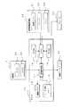
図2は、本発明に係る車両周辺監視装置の構成を示すブロック図である。上述のように、車両1に搭載される車両周辺監視装置は、車両1の前方及び後方を撮像する2つのカメラ50、50を有する撮像部2と、カメラ50、50により撮像された画像、カーナビゲーション装置の地図画像又はチューナが受信したテレビ番組等の表示を行う液晶ディスプレイ20と、液晶ディスプレイ20に表示する画像を自動的に切り替える処理を主として行うECU10とを備えている。撮像部2のカメラ50、50及びECU10と、ECU10及び液晶ディスプレイ20とは、それぞれ接続ケーブル又はネットワークケーブル等により接続してある。 FIG. 2 is a block diagram showing the configuration of the vehicle periphery monitoring apparatus according to the present invention. As described above, the vehicle periphery monitoring device mounted on the
詳細は後述するが、撮像部2のカメラ50、50は、CCD又はCMOS等の撮像素子と、この撮像素子へ光を集光する一又は複数のレンズとをそれぞれ有しており、レンズが集光した光を撮像素子が検知することによって、1秒間に30回程度の頻度で撮像を行う装置である。カメラ50、50のレンズには、広角レンズ又は魚眼レンズ等の画角が広いレンズが用いられる。カメラ50、50は車両1の前方及び後方をそれぞれ撮像して画像を取得し、取得した画像をECU10へそれぞれ与えるようにしてある。 Although details will be described later, the
ECU10は、撮像部2のカメラ50、50からの画像が与えられ、与えられた画像に対して種々の画像処理を行う画像処理部11を備えている。また、画像処理部11には、カメラ50、50から与えられた画像及び画像処理後の画像等の種々の画像を一時的に蓄積するための画像メモリ12と、カメラ50、50から与えられた画像の補正又は視点変換等を行うためのテーブルが記憶されたテーブル用メモリ13とが接続してある。画像メモリ12は、SRAM又はDRAM等の書き換え可能なメモリ素子により構成してあり、テーブル用メモリ13は、マスクROM又はEEPROM等の不揮発性のメモリ素子により構成してある。また、画像処理部11には液晶ディスプレイ20が接続してあり、カメラ50、50から与えられた画像に画像処理を施して、液晶ディスプレイ20へ表示することができるようにしてある。 The
カメラ50、50は広角レンズ又は魚眼レンズ等のレンズにより撮像を行うため、得られる画像は中央から端部へ向けて徐々に湾曲度合いが大きくなる。よって、画像処理部11では、カメラ50、50から与えられた画像の湾曲部分を補正し、補正後の画像を液晶ディスプレイ20へ表示することができるようにしてある。湾曲部分の補正は、テーブル用メモリ13に予め記憶してある補正テーブルを用いて行うようにしてある。画像処理部11は、カメラ50、50から与えられた画像の各画素を補正テーブルにて定められた位置に移動させることによって、画像の湾曲部分を補正するようにしてあり、補正テーブルには各画素の移動先が記憶してある。 Since the
また、画像処理部11は、カメラ50、50が撮像して取得した画像を俯瞰方向の画像に変換するTopview変換を行って、車両1が走行する路面を上から見た画像を液晶ディスプレイ20に表示することができるようにしてある。Topview変換は、テーブル用メモリ13に予め記憶してある変換テーブルを用いて行うようにしてある。画像処理部11は、カメラ50、50から与えられた画像の各画素を変換テーブルにて定められた位置に移動させることによって、正面から撮像した画像を俯瞰方向の画像に変換するようにしてあり、変換テーブルには各画素の移動先が記憶してある。 In addition, the image processing unit 11 performs Topview conversion that converts an image captured and acquired by the
また、ECU10には、車両1の走行に係る情報を取得する車両情報取得部30から、車両1の走行に係る情報が与えられている。車両情報取得部30では、車両1のハンドルの舵角を検知する舵角センサ31から舵角情報を取得し、車両1のワイパー32が動作しているか否かに係る情報を取得し、車両1のヘッドランプ又はテールランプ等のランプ33が点灯しているか否かに係る情報を取得するようにしてある。更に、図示は省略するが、車速センサから車両1の車速情報を取得し、加速度センサから車両1の加速度情報を取得し、シフトレバーの状態情報を取得し、サイドレバーの状態情報を取得するなど、種々の情報を取得するようにしてある。 Further, the
ECU10は、車両情報取得部30から与えられた情報を基に、車両1に搭載された電子機器及び画像処理部11等の制御を行うCPU15を備えており、CPU15にはROM14及びRAM16が接続してある。ROM14は、CPU15にて実行される種々の制御プログラムを予め記憶しており、マスクROM、EEPROM又はフラッシュメモリ等の不揮発性のメモリ素子により構成してある。RAM16は、CPU15が制御処理又は演算処理等を行う際に生じる一時的なデータを記憶するものであり、SRAM、DRAM又はフラッシュメモリ等の書き換え可能なメモリ素子により構成してある。CPU15は、ROM14から制御プログラムを読み出して実行することにより、例えばABS(Antirock Brake System)又はTCS(Traction Control System)等の車両1の電気的な制御を行うようにしてある。また、車両1の運転席近傍には、警告音及び音声メッセージ等の音声出力を行うスピーカ25を備えており、CPU15からの出力指示に応じて音声出力を行うことができるようにしてある。 The
図3は、本発明に係る車両周辺監視装置のカメラ50の構成を示すブロック図であり、車両1に搭載された2つのカメラ50、50のうちの一方のカメラ50について図示してあるが、他方のカメラ50についても同様の構成である。また、図3においては、カメラ50が撮像して取得した画像に係るデータの流れを実線の矢印で示し、制御信号又はその他のデータの流れを破線の矢印で示してある。 FIG. 3 is a block diagram showing the configuration of the
カメラ50は、図示しない一又は複数のレンズにより集光される光に応じてアナログの電気信号を出力するCCD又はCMOS等の撮像素子51を有している。撮像素子51が出力するアナログの電気信号は利得制御部52へ与えられ、利得制御部52は、後述のDSP54が有する測光計算部56から与えられる情報に基づいて、撮像素子51から与えられた電気信号を増幅して出力するようにしてある。利得制御部52により増幅された電気信号は、A/D変換部53へ与えられるようにしてあり、A/D変換部53は与えられたアナログの電気信号をデジタルの電気信号に変換して出力するようにしてある。 The
A/D変換部53が出力したデジタルの電気信号は、DSP54へ与えられるようにしてある。DSP54はデジタル信号処理部55及び測光計算部56等を有している。デジタル信号処理部55は、与えられたデジタルの電気信号に対して画素補間、ホワイトバランス調整、彩度調整及びノイズ除去等の種々の信号処理を行うものである。測光計算部56は、デジタル信号処理部55により信号処理された電気信号を基に、撮像素子51により撮像された画像の所定領域、例えば画像の中心領域などの輝度と、画像全体の輝度とを計算し、撮像素子51により撮像される画像が予め定められた輝度となるように利得制御部52及び露光制御部57へ制御情報を与えるようにしてある。露光制御部57は、測光計算部56から与えられる情報に基づいて、撮像素子51の露光時間を制御するようにしてある。なお、DSP54は、デジタル信号処理部55が行ったホワイトバランス調整又は彩度調整等の処理条件、並びに測光計算部56が利得制御部52及び露光制御部57へ与えた制御情報に係る制御条件等の種々の条件を撮像条件としてECU10の画像処理部11へ与えるようにしてある。 The digital electric signal output from the A /
エンコーダ58は、DSP54のデジタル信号処理部55から与えられたデジタルの電気信号を、NTSC(National Television Standards Committee)方式の信号に符号化して出力するものである。なお、NTSC方式とは、テレビジョン装置に出力するための映像信号に係る方式である。エンコーダ58により符号化されたデジタルの電気信号はECU10の画像処理部11へ与えられるようにしてある。ECU10の画像処理部11は、カメラ50が撮像した画像及びカメラ50が撮像を行ったときの撮像条件をカメラ50から与えられ、これらを対応付けて画像メモリ12に蓄積すると共に、与えられた画像に種々の画像処理を行って液晶ディスプレイ20に表示するようにしてある。 The encoder 58 encodes a digital electric signal given from the digital
また、本発明に係る車両周辺監視装置の画像処理部11は、車両1の前部及び後部に搭載された2つのカメラ50、50がそれぞれ撮像して取得した2つの画像のうち、いずれの画像を液晶ディスプレイ20に表示するかを選択し、自動的に液晶ディスプレイ20に表示する画像を切り替える処理を行うようにしてある。更に、画像処理部11は、カーナビゲーション装置又はテレビ番組を受信するチューナ等の装置(図示せず)が車両1に搭載されている場合には、これらの装置が出力する画像又はカメラ50、50が撮像した画像のうちのいずれかの画像を選択して液晶ディスプレイ20に表示するようにしてある。 In addition, the image processing unit 11 of the vehicle periphery monitoring device according to the present invention can select any of the two images acquired by the two
このような場合、常時において画像処理部11は、カーナビゲーション装置の案内用の地図画像又はチューナが受信したテレビ番組のいずれかを運転者の選択に従って液晶ディスプレイ20に表示するようにしてある。ただし、バックグラウンド処理により、カメラ50、50が撮像する車両1の周囲の画像に歩行者又は他車両等が写されたか否かを判定し、画像に歩行者又は他車両等が写されたと判定した場合には、カーナビゲーション装置の案内用の地図画像又はチューナが受信したテレビ番組等の表示を停止し、歩行者又は他車両等が写された画像を選択して液晶ディスプレイ20に表示するようにしてある。 In such a case, the image processing unit 11 always displays either the map image for guidance of the car navigation device or the television program received by the tuner on the
なお、カメラ50、50が撮像する画像に歩行者又は他車両等が写されたか否かの判定は、車両1が走行していない場合にカメラ50、50が時刻t1に撮像した画像と、所定時間T後の時刻t2(=t1+T)に撮像した画像とを画像メモリ12から読み出し、例えば2つの画像の輝度値の差分を算出して、2つの画像の変化を検出することによって行うことができる。即ち、車両1が走行しておらず、異なる時刻に撮像された2つの画像に変化が検出された場合には、この変化が生じた部分に歩行者又は他車両等が写されたと判定することができる。この処理を画像処理部11では1秒間に数回〜十数回程度繰り返して行い、画像に変化が生じた場合には歩行者又は他車両等が画像に写された、即ち車両1の周囲に歩行者又は他車両等が存在すると判定して、この画像を液晶ディスプレイ20に表示し、運転者へ注意を促すようにしてある。 It should be noted that whether or not a pedestrian or another vehicle is captured in an image captured by the
また、本発明に係る車両周辺監視装置の画像処理部11は、時刻t1に撮像した画像及び時刻t2に撮像した画像を比較して変化の検出を行う場合に、画像の全領域について比較を行うのではなく、制限された検出範囲内でのみ比較を行って変化を検出するようにしてある。図4は、検出範囲の制限例を示す模式図であり、(a)は車両1の前部に搭載されたカメラ50が撮像した画像の一例であり、(b)はこの画像に検出範囲を重ねて図示したものである。 In addition, the image processing unit 11 of the vehicle periphery monitoring device according to the present invention compares the entire image area when detecting a change by comparing the image captured at the time t1 and the image captured at the time t2. Instead, a comparison is made only within a limited detection range to detect a change. FIG. 4 is a schematic diagram illustrating an example of a detection range restriction. FIG. 4A is an example of an image captured by the
カメラ50は、魚眼レンズ又は広角レンズ等のレンズで撮像を行うカメラであり、180°又はそれ以上の画角を有しているため、撮像により取得する画像は端部分が湾曲した画像となる。例えば、図4に示す画像は車両1が交差点に進入したときの画像であり、本来は直線の道路が湾曲して写されているが、カメラ50の画角が広いため左右方向の道路の遠方まで撮像されている。このような画角の広いカメラ50を車両1に搭載することで、運転者は車内から広範囲に亘って車両1周辺の様子を視認することが可能となる。 The
しかし、上述のように異なる時刻に撮像した2つの画像を比較して変化を検出し、歩行者又は他車両等の検出を行う場合には、接触又は衝突等の虞がある車両1近傍の歩行者又は他車両等のみを検出すればよく、車両1から十分に離れた位置に存在する歩行者又は他車両等を検出する必要性は少ない。よって、本発明に係る車両周辺監視装置では、図4(b)に示す検出範囲101内でのみ、画像の比較を行って変化を検出するようにしてある。例えば、検出範囲101は、略矩形をなす画像の下辺の略中央の80%を占める下底と、画像中の水平線の位置より下側に設けられ、下底より若干短い上底とを有する略台形の範囲とすることができる。 However, in the case where a change is detected by comparing two images taken at different times as described above to detect a pedestrian or another vehicle, walking in the vicinity of the
図5乃至図7は、車両1の周辺と検出範囲101との対応を示す模式図であり、(a)に車両1及びその周辺を図示し、(b)に車両1の前部のカメラ50が撮像した画像中の検出範囲101を図示し、(c)に車両1の後部のカメラ50が撮像した画像中の検出範囲101を図示してある。カメラ50、50により撮像された画像中の検出範囲101は画像の下側から略中央までを占める略台形の範囲であるが(図5(b)及び(c)参照)、これは車両1の前進方向及び後退方向に対して車両1から数m程度の略矩形の範囲(図5(c)参照)、即ち車両1が走行する可能性がある経路上の数m程度の範囲に相当する。 5 to 7 are schematic diagrams showing the correspondence between the vicinity of the
このように、検出範囲101を車両1の走行経路上の所定の距離範囲に制限することによって、車両1の走行により接触又は衝突等が発生する虞のある歩行者又は他車両等のみを検出することができる。また、カメラ50、50は上述のように画角の広いカメラであり、車両1の周辺を広範囲に亘って撮像することができるが、車両1から遠方の部分は画像中では小さく写されるため、変化の検出を行う場合に精度が低く、誤検出が発生する虞がある。よって、検出範囲101を車両1の近い部分に制限することで検出の精度の低下を防止できる。また、画像の全範囲について検出を行う場合と比較して計算量を低減できるため、処理を高速に行うことができる。 In this way, by limiting the
更に、本発明に係る車両周辺監視装置は、車両1のハンドルの舵角を車両情報取得部30の舵角センサ31から取得し、舵角に応じて検出範囲101を調整するようにしてある。例えば、ハンドルを右に回転させた場合、検出範囲101は、下底は変化せず、上底が画像の右辺に寄った略台形となる。これは、車両1の前部に搭載されたカメラ50が撮像した画像(図6(b)参照)の場合も、後部に搭載されたカメラ50が撮像した画像(図6(c)参照)の場合も同様である。この検出範囲101は、車両1の周辺では、ハンドルの舵角に応じた角度だけ右側に傾いた略平行四辺形の範囲に相当する(図6(a)参照)。このように、ハンドルの舵角に応じて検出範囲101を調整することによって、車両1の走行経路上の歩行者又は他車両等をより精度よく検出できる。 Furthermore, the vehicle periphery monitoring apparatus according to the present invention acquires the steering angle of the steering wheel of the
更に、本発明に係る車両周辺監視装置は、カメラ50、50が撮像して取得した画像の各画素の輝度値に応じて、検出範囲101を調整するようにしてある。例えば車両1の周辺に光量の多い発光体が存在する場合に、カメラ50、50が撮像した画像中の発光体及びこの近傍が写された部分が全て略白色に写される所謂白飛びが発生する虞がある。また、光が照射されにくく他より暗い部分が車両1の周辺に存在する場合、この部分が全て略黒色に写される所謂黒つぶれが発生する虞がある。車両1の周辺に光量が多く他より明るい部分及び光量が少なく他より暗い部分が存在し(図7(a)参照)、画像中に白飛び又は黒つぶれが発生した場合、この部分では上述のような検出を精度よく行うことができないため、この部分を検出範囲101から除外する。 Furthermore, the vehicle periphery monitoring apparatus according to the present invention adjusts the
よって、カメラ50、50により撮像された画像の各画素の輝度をLiとした場合、ECU10の画像処理部11は、上述の検出を行う前に検出範囲101中の各画素の輝度Liが予め定められた上限値A及び下限値Bの間に収まるか否か、即ちA<Li<Bが成立するか否かを判定し、これが成立しない範囲を検出範囲101から除外するようにしてある(図7(b)及び(c)参照)。 Therefore, when the luminance of each pixel of the images captured by the
更に、本発明に係る車両周辺監視装置は、車両1のワイパー32の動作状態及びランプ33の点灯状態に係る情報を車両情報取得部30から取得し、取得した情報に応じて、カメラ50、50が撮像した画像を基に行う歩行者又は他車両等の検出、及びこの検出結果に基づいて液晶ディスプレイ20に表示する画像を自動的に切り替える処理を停止するようにしてある。 Furthermore, the vehicle periphery monitoring device according to the present invention acquires information on the operation state of the
車両1のワイパー32が動作している場合、車両1の周辺環境は雨天である可能性が高い。雨天時にカメラ50、50が撮像する画像には雨が写されるため、異なる時刻の2つの画像を比較した場合に画像の全範囲にわたって変化が検出され、歩行者又は他車両等による変化を精度よく検出できない虞がある。また、車両1のランプ33が点灯している場合、車両1の周辺環境は夜間である可能性が高い。夜間にカメラ50、50が撮像する画像は上述のような白飛び及び黒つぶれが生じる部分が多く、歩行者又は他車両等による変化を精度よく検出できない虞がある。 When the
よって、ワイパー32が動作している場合及びランプ33が点灯している場合には、検出した画像の変化に応じてカメラ50、50が撮像した画像を液晶ディスプレイ20に自動的に切り替えて表示する処理を停止することにより、誤検出が発生する虞がある状況で画像の誤表示を行うことを防止する。また、処理を停止していることを運転者に認識させるため、処理を停止している場合には液晶ディスプレイ20に「画像の自動切換え処理を停止しています」などのメッセージを、カーナビゲーション装置の地図画像又はチューナが受信したテレビ番組等に重ねて表示するようにしてある。 Therefore, when the
更に、本発明に係る車両周辺監視装置は、異なる時刻に撮像された2つの画像を比較して変化を検出する処理の精度を高めるために、カメラ50、50が撮像して取得した画像を撮像条件に応じて補正する処理を行うようにしてある。カメラ50、50では、周辺の環境の変化に応じて自動的に利得制御部52及び露光制御部57にて利得及び露光時間の制御が行われ、また、デジタル信号処理部55にてホワイトバランス調整及び彩度調整等が行われる。よって、時刻t1及び時刻t2の2つの時刻で撮像した画像を比較して変化の検出を行うときに、例えば時刻t1と時刻t2との間で車両1の周辺の光量が変化した場合、カメラ50、50による撮像条件が自動的に変更され、2つの画像の全体に亘って変化が検出される虞がある。 Furthermore, the vehicle periphery monitoring device according to the present invention captures images acquired by the
よって、ECU10の画像処理部11は、カメラ50、50のDSP54から与えられた撮像条件を基に、2つの画像の撮像条件の差異を打ち消すようにいずれか一方又は両方の画像を補正するようにしてある。これにより、撮像条件の変化によって画像の全体に亘って変化が検出されることを防止でき、歩行者又は他車両等による画像の変化のみを精度よく検出することができる。 Therefore, the image processing unit 11 of the
図8は、本発明に係る車両周辺監視装置が行う画像表示処理の手順を示すフローチャートである。液晶ディスプレイ20に画像の表示を行う場合、まず、車両1のワイパー32の動作状態を車両情報取得部30から取得し(ステップS1)、取得した情報からワイパー32が動作しているか否かを調べる(ステップS2)。ワイパー32が動作していない場合(S2:NO)、更に、車両1のランプ33の点灯状態を車両情報取得部30から取得し(ステップS3)、ランプ33が点灯しているか否かを調べる(ステップS4)。 FIG. 8 is a flowchart showing a procedure of image display processing performed by the vehicle periphery monitoring device according to the present invention. When displaying an image on the
ステップS2にてワイパー32が動作している場合(S2:YES)、又はステップS4にてランプ33が点灯している場合(S4:YES)、カメラ50、50が撮像した画像を自動的に切り替えて液晶ディスプレイ20に表示する処理を行わず、切替処理を停止した旨を運転者に報知するメッセージを液晶ディスプレイ20に表示すると共に(ステップS11)、カーナビゲーション装置又はチューナ等の他の装置から与えられた画像を液晶ディスプレイ20に表示する(ステップS12)。 When the
ステップS4にてランプが点灯していない場合(S4:NO)、車両1の前部に搭載されたカメラ50により撮像された2つの画像を基に、画像中に生じた変化を検出する変化検出処理を行う(ステップS5)。この変化検出処理は上述の方法により行われるものであり、処理手順については後述する。変化検出処理により変化が検出されたか否かを調べ(ステップS6)、変化が検出された場合には(S6:YES)、車両1の前部に搭載されたカメラ50が撮像した画像を液晶ディスプレイ20に表示する(ステップS7)。 When the lamp is not lit in step S4 (S4: NO), change detection for detecting a change occurring in the image based on the two images captured by the
車両1の前部のカメラ50について行った変化検出処理にて変化が検出されなかった場合(S6:NO)、更に車両1の後部に搭載されたカメラ50により撮像された2つの画像を基に、画像中に生じた変化を検出する変化検出処理を行う(ステップS8)。変化検出処理により変化が検出されたか否かを調べ(ステップS9)、変化が検出された場合には、(S9:YES)、車両1の後部に搭載されたカメラ50が撮像した画像を液晶ディスプレイ20に表示する(ステップS10)。変化検出処理により変化が検出されなかった場合(S9:NO)、カーナビゲーション装置又はチューナ等の他の装置から与えられた画像を液晶ディスプレイ20に表示する(ステップS12)。本発明に係る車両周辺監視装置では以上の画像表示処理を1秒間に数回程度の頻度で繰り返し行っており、車両1の前部に搭載されたカメラ50が撮像した画像、後部に搭載されたカメラ50が撮像した画像、又は他の装置から与えられた画像を自動的に切り替えて表示するようにしてある。 If no change is detected in the change detection process performed for the
図9は、本発明に係る車両周辺監視装置が行う変化検出処理の手順を示すフローチャートであり、図8のステップS5及びS8にて行われるサブルーチンである。車両周辺監視装置ではカメラ50、50が撮像して取得した画像はECU10の画像メモリ12に蓄積されており、変化検出処理では、まず、画像メモリ12から最新の画像(時刻t2の画像)を読み出すと共に(ステップS31)、この画像をカメラ50、50が撮像したときの撮像条件を読み出す(ステップS32)。更に所定時間T前の画像(時刻t1の画像)を画像メモリ12から読み出すと共に(ステップS33)、この画像をカメラ50、50が撮像したときの撮像条件を読み出す(ステップS34)。 FIG. 9 is a flowchart showing the procedure of change detection processing performed by the vehicle periphery monitoring apparatus according to the present invention, and is a subroutine performed in steps S5 and S8 of FIG. In the vehicle periphery monitoring apparatus, images acquired by the
次いで、2つの画像の撮像条件を比較して、撮像条件が同じであるか否かを調べ(ステップS35)、撮像条件が異なる場合には(S35:NO)、撮像条件の差異を打ち消すように、いずれか一方又は両方の画像の補正を行う(ステップS36)。撮像条件が同じ場合(S35:YES)、又は画像の補正を終了した後、車両情報取得部30の舵角センサ31から車両1のハンドルの舵角を取得して(ステップS37)、図6に示すように舵角に応じて検出範囲101を決定する(ステップS38)。 Next, the imaging conditions of the two images are compared to determine whether the imaging conditions are the same (step S35). If the imaging conditions are different (S35: NO), the difference between the imaging conditions is canceled out. Then, either or both of the images are corrected (step S36). When the imaging conditions are the same (S35: YES), or after correcting the image, the steering angle of the steering wheel of the
次いで、2つの画像の各画素の輝度値を調べて、各画素の輝度値が輝度上限Aより大きい範囲を検出範囲101から除外すると共に(ステップS39)、輝度下限Bより小さい範囲を検出範囲101から除外する(ステップS40)。これにより、検出範囲101が確定するため、この検出範囲101内で2つの画像の比較を行い(ステップS41)、2つの画像に変化があるか否かを調べる(ステップS42)。変化がある場合には(S42:YES)、変化検出判定をこのサブルーチンの呼び出し元へ返し(ステップS43)、変化がない場合には(S42:NO)、変化非検出判定を返して(ステップS44)、変化検出処理を終了する。 Next, the luminance value of each pixel of the two images is examined, and a range where the luminance value of each pixel is larger than the luminance upper limit A is excluded from the detection range 101 (step S39), and a range smaller than the luminance lower limit B is detected. (Step S40). Thereby, since the
以上の構成の車両周辺監視装置においては、異なる時刻に撮像された2つの画像を比較して変化を検出する場合に、図4及び図5に示すように検出を行う範囲を制限することによって、車両1の走行経路上に存在する歩行者又は他車両等のみを精度よく検出して、液晶ディスプレイ20に表示する画像の切り替えを精度よく行うことができる。また、舵角センサ31により車両1のハンドルの舵角を取得し、検出範囲101を舵角に応じて調整することにより、車両1の走行経路上に存在する歩行者又は他車両等のみをより確実に検出することができる。また、カメラ50、50が撮像した画像の各画素の輝度が輝度上限Aより大きい範囲及び輝度下限Bより小さい範囲を検出範囲101から除外する調整を行うことにより、画像中に生じた白飛び及び黒つぶれによる検出精度の低下を防止できる。 In the vehicle periphery monitoring device having the above configuration, when a change is detected by comparing two images captured at different times, by limiting the detection range as shown in FIGS. 4 and 5, Only the pedestrians or other vehicles existing on the travel route of the
また、車両1のワイパー32の動作中及びランプ33の点灯中にはカメラ50、50が撮像した画像を自動的に切り替えて液晶ディスプレイ20に表示する処理を停止することで、雨天又は夜間に誤検出により画像が切り替えられて表示されることを防止でき、また、処理を停止した場合には液晶ディスプレイ20にメッセージを表示して報知を行うことで、処理を停止していることを運転者に確実に認識させることができる。また、カメラ50、50が撮像を行ったときの撮像条件を画像と共に画像メモリ12に記憶しておき、2つの画像の比較を行うときに撮像条件の差異を打ち消すように補正を行うことにより、2つの画像を比較して変化を検出する精度を高めることができる。 In addition, during the operation of the
なお、本実施の形態においては、車両1の前部及び後部にカメラ50、50を搭載する構成としたが、これに限るものではなく、車両の側部、上部又は下部等の他の場所にカメラ50を搭載する構成としてもよい。また、車両1に2つのカメラ50、50を搭載する構成としたが、これに限るものではなく、1つ又は3つ以上のカメラを搭載する構成としてもよい。また、図4〜図7にて検出範囲101の形状を略台形としたが、これに限るものではなく、その他の形状であってもよい。また、検出範囲101を舵角センサ31が検出するハンドルの舵角に応じて調整する構成としたが、調整を行わない構成としてもよい。また、カメラ50、50が撮像して取得した画像の各画素の輝度が輝度上限A及び輝度下限Bに収まらない範囲を検出範囲101から除外する構成としたが、これを行わない構成としてもよい。 In the present embodiment, the
車両1のワイパー32が動作しているか否かに応じて雨天であるか否かを検知し、これに応じて画像の切替表示の処理を行うか否かを決定する構成としたが、これに限るものではなく、例えば車両1に雨滴を検知する雨滴センサを搭載して雨天であるか否かを検知する構成としてもよく、車両1の周囲の気圧を検知するセンサを搭載して気圧に応じて雨天であるか否かを検知する構成としてもよく、他のセンサにより雨天であるか否かを検知する構成としてもよい。また、車両1のランプ33が転倒しているか否かに応じて夜間であるか否かを検知し、これに応じて画像の切替表示の処理を行うか否かを決定する構成としたが、これに限るものではなく、例えば車両1に明るさを検知する照度センサを搭載して夜間であるか否かを検知する構成としてもよく、車両1に搭載された時計による現在時刻に応じて夜間であるか否かを検知する構成としてもよく、他のセンサにより夜間であるか否かを検知する構成としてもよい。 Although it is configured to detect whether or not it is raining according to whether or not the
また、車両1のワイパー32の動作中及びランプ33の点灯中には変化の検出及び画像の切替表示の処理を行わない構成としたが、行う構成としてもよい。また、変化の検出及び画像の切替表示の処理を行わない場合に、液晶ディスプレイ20にメッセージを表示して報知を行う構成としたが、これに限るものではなく、音声出力又はランプの点灯等の他の方法により報知を行う構成としてもよく、報知を行わない構成としてもよい。また、カメラ50、50が撮像を行ったときの撮像条件を取得して画像の補正を行う構成としたが、補正を行わない構成としてもよい。 In addition, while the
また、図8に示す画像表示処理では、前部のカメラ50が撮像した画像に変化が生じた場合に、優先して前部のカメラ50が撮像した画像を液晶ディスプレイ20に表示するフローとしてあるが、これに限るものではなく、後部のカメラ50を優先する構成としてもよく、また、例えば車両1のシフトレバーの状態を取得して、シフトレバーが「D」のときには前部のカメラ50を優先し、「R」のときには後部のカメラ50を優先する構成としてもよい。 Further, the image display process shown in FIG. 8 is a flow in which an image captured by the
1 車両
2 撮像部(撮像手段)
10 ECU(検出手段、制限手段、表示処理手段、報知手段、判定手段、補正手段)
11 画像処理部
12 画像メモリ
13 テーブル用メモリ
14 ROM
15 CPU
16 RAM
20 液晶ディスプレイ(表示手段)
25 スピーカ
30 車両情報取得部(検知手段)
31 舵角センサ
32 ワイパー
33 ランプ
50 カメラ(撮像手段)
51 撮像素子
52 利得制御部
53 A/D変換部
54 DSP(取得手段)
55 デジタル信号処理部
56 測光計算部
57 露光制御部
58 エンコーダ
101 検出範囲DESCRIPTION OF
10 ECU (detection means, restriction means, display processing means, notification means, determination means, correction means)
11 Image Processing Unit 12 Image Memory 13
15 CPU
16 RAM
20 Liquid crystal display (display means)
25
31
51 Image Sensor 52 Gain Control Unit 53 A /
55 Digital
Claims (8)
Translated fromJapanese前記撮像手段が異なる時点で撮像して取得した複数の画像を基に、画像の変化を検出する検出手段と、
該検出手段が検出を行う画像の範囲を制限する制限手段と、
前記検出手段の検出結果に応じて、前記撮像手段が撮像した画像を前記表示手段に表示させる処理を行う表示処理手段と
を備え、
前記制限手段は、前記車両の前進方向又は後退方向について前記車両から所定の範囲内に、検出を行う画像の範囲を制限するようにしてあること
を特徴とする車両周辺監視装置。In a vehicle periphery monitoring device that is mounted on a vehicle and includes an imaging unit that captures an image of the outside world of the vehicle to acquire an image, and a display unit that displays an image acquired by the imaging unit.
Detection means for detecting a change in an image based on a plurality of images obtained by imaging at different time points of the imaging means;
Limiting means for limiting the range of images detected by the detection means;
Display processing means for performing processing for causing the display means to display an image picked up by the image pickup means in accordance with a detection result of the detection means,
The vehicle periphery monitoring device, wherein the limiting means limits a range of an image to be detected within a predetermined range from the vehicle in a forward direction or a backward direction of the vehicle.
前記制限手段は、前記車両の前進方向及び後退方向の両方向について前記車両から所定の距離範囲内に、検出を行う画像の範囲を制限するようにしてある請求項1に記載の車両周辺監視装置。The imaging means is capable of imaging the front and rear of the vehicle,
2. The vehicle periphery monitoring device according to claim 1, wherein the limiting unit limits a range of an image to be detected within a predetermined distance range from the vehicle in both a forward direction and a backward direction of the vehicle.
前記制限手段は、前記検知手段の検知結果に応じて、制限する画像の範囲を調整するようにしてある請求項1又は請求項2に記載の車両周辺監視装置。A detecting means for detecting a steering angle of the steering wheel of the vehicle;
The vehicle periphery monitoring device according to claim 1, wherein the restriction unit adjusts a range of an image to be restricted according to a detection result of the detection unit.
前記制限手段は、各画素の輝度が所定輝度内に収まる範囲に、制限する画像の範囲を調整するようにしてある請求項1乃至請求項3のいずれか1つに記載の車両周辺監視装置。The image acquired by the imaging means is composed of a plurality of pixels,
The vehicle periphery monitoring device according to any one of claims 1 to 3, wherein the limiting unit adjusts a range of an image to be limited within a range in which the luminance of each pixel is within a predetermined luminance.
前記表示処理手段は、前記車両の周囲の環境が雨天である場合に、前記検出手段の検出結果に応じた前記表示手段による画像の表示を行わせないようにしてある請求項1乃至請求項4のいずれか1つに記載の車両周辺監視装置。Comprising detection means for detecting whether or not the environment around the vehicle is rainy,
5. The display processing unit is configured to prevent the display unit from displaying an image according to a detection result of the detection unit when the environment around the vehicle is rainy. The vehicle periphery monitoring apparatus as described in any one of these.
前記表示処理手段は、前記車両の周囲の環境が夜間である場合に、前記検出手段の検出結果に応じた前記表示手段による画像の表示を行わせないようにしてある請求項1乃至請求項5のいずれか1つに記載の車両周辺監視装置。Comprising detection means for detecting whether or not the environment around the vehicle is at night,
6. The display processing unit is configured to prevent the display unit from displaying an image according to a detection result of the detection unit when the environment around the vehicle is night. The vehicle periphery monitoring apparatus as described in any one of these.
前記検出手段が変化を検出する複数の画像について、前記取得手段が取得したそれぞれの撮像条件が同じであるか否かを判定する判定手段と、
前記複数の画像の撮像条件が同じでない場合に、撮像条件の差異に応じて画像の補正を行う補正手段と
を備える請求項1乃至請求項7のいずれか1つに記載の車両周辺監視装置。Acquisition means for acquiring an imaging condition when the imaging means acquires an image by acquiring an image;
Determination means for determining whether or not the respective imaging conditions acquired by the acquisition means are the same for a plurality of images for which the detection means detects a change;
The vehicle periphery monitoring device according to any one of claims 1 to 7, further comprising: correction means that corrects an image according to a difference in imaging conditions when imaging conditions of the plurality of images are not the same.
Priority Applications (1)
| Application Number | Priority Date | Filing Date | Title |
|---|---|---|---|
| JP2006276806AJP2008098858A (en) | 2006-10-10 | 2006-10-10 | Vehicle periphery monitoring device |
Applications Claiming Priority (1)
| Application Number | Priority Date | Filing Date | Title |
|---|---|---|---|
| JP2006276806AJP2008098858A (en) | 2006-10-10 | 2006-10-10 | Vehicle periphery monitoring device |
Publications (1)
| Publication Number | Publication Date |
|---|---|
| JP2008098858Atrue JP2008098858A (en) | 2008-04-24 |
Family
ID=39381266
Family Applications (1)
| Application Number | Title | Priority Date | Filing Date |
|---|---|---|---|
| JP2006276806APendingJP2008098858A (en) | 2006-10-10 | 2006-10-10 | Vehicle periphery monitoring device |
Country Status (1)
| Country | Link |
|---|---|
| JP (1) | JP2008098858A (en) |
Cited By (9)
| Publication number | Priority date | Publication date | Assignee | Title |
|---|---|---|---|---|
| JP2010069943A (en)* | 2008-09-16 | 2010-04-02 | Honda Motor Co Ltd | Vehicle surroundings monitoring apparatus |
| JP2011085979A (en)* | 2009-10-13 | 2011-04-28 | Honda Elesys Co Ltd | In-vehicle image recognition system |
| JP2011216979A (en)* | 2010-03-31 | 2011-10-27 | Fujitsu Ten Ltd | Image generation apparatus, image display system, and image generation method |
| JP2011253448A (en)* | 2010-06-03 | 2011-12-15 | Denso Corp | Vehicle periphery monitoring device |
| JP2012238239A (en)* | 2011-05-12 | 2012-12-06 | Fuji Heavy Ind Ltd | Environment recognition device and environment recognition method |
| CN103996182A (en)* | 2013-02-15 | 2014-08-20 | 欧姆龙株式会社 | Image processing device, image processing method, and image processing program |
| JP2016118912A (en)* | 2014-12-19 | 2016-06-30 | 日立建機株式会社 | Surrounding monitoring device of work machine |
| JP2020080544A (en)* | 2018-10-03 | 2020-05-28 | 株式会社ユピテル | Vehicle video recording device, playback device, program |
| JP2020141288A (en)* | 2019-02-28 | 2020-09-03 | キヤノン株式会社 | Information processing equipment, information processing methods, and programs |
- 2006
- 2006-10-10JPJP2006276806Apatent/JP2008098858A/enactivePending
Cited By (12)
| Publication number | Priority date | Publication date | Assignee | Title |
|---|---|---|---|---|
| JP2010069943A (en)* | 2008-09-16 | 2010-04-02 | Honda Motor Co Ltd | Vehicle surroundings monitoring apparatus |
| JP2011085979A (en)* | 2009-10-13 | 2011-04-28 | Honda Elesys Co Ltd | In-vehicle image recognition system |
| JP2011216979A (en)* | 2010-03-31 | 2011-10-27 | Fujitsu Ten Ltd | Image generation apparatus, image display system, and image generation method |
| JP2011253448A (en)* | 2010-06-03 | 2011-12-15 | Denso Corp | Vehicle periphery monitoring device |
| JP2012238239A (en)* | 2011-05-12 | 2012-12-06 | Fuji Heavy Ind Ltd | Environment recognition device and environment recognition method |
| CN103996182A (en)* | 2013-02-15 | 2014-08-20 | 欧姆龙株式会社 | Image processing device, image processing method, and image processing program |
| US20140233796A1 (en)* | 2013-02-15 | 2014-08-21 | Omron Corporation | Image processing device, image processing method, and image processing program |
| JP2014157452A (en)* | 2013-02-15 | 2014-08-28 | Omron Corp | Image processing apparatus, image processing method, and image processing program |
| US9552646B2 (en) | 2013-02-15 | 2017-01-24 | Omron Corporation | Image processing device, image processing method, and image processing program, for detecting an image from a visible light image and a temperature distribution image |
| JP2016118912A (en)* | 2014-12-19 | 2016-06-30 | 日立建機株式会社 | Surrounding monitoring device of work machine |
| JP2020080544A (en)* | 2018-10-03 | 2020-05-28 | 株式会社ユピテル | Vehicle video recording device, playback device, program |
| JP2020141288A (en)* | 2019-02-28 | 2020-09-03 | キヤノン株式会社 | Information processing equipment, information processing methods, and programs |
Similar Documents
| Publication | Publication Date | Title |
|---|---|---|
| US12118806B2 (en) | Vehicular imaging system | |
| JP2008098858A (en) | Vehicle periphery monitoring device | |
| JP5421072B2 (en) | Approaching object detection system | |
| EP2471691B1 (en) | Obstacle detection device, obstacle detection system provided therewith, and obstacle detection method | |
| JP4611899B2 (en) | Camera lens dirt detection device and image display system | |
| KR100917330B1 (en) | Vehicle top view monitor system and method | |
| US20070263090A1 (en) | Method and Apparatus for Automatic Exposure of an In-Vehicle Camera | |
| JP2009255722A (en) | Traveling environment detection method and lighting unit control device for vehicle | |
| JP2007257449A (en) | Road marking line detection device | |
| JP2007164636A (en) | Road marking line detection device | |
| JP2000207563A (en) | Image recognizing device | |
| JP2008306402A (en) | In-vehicle imaging display device | |
| JP2020060531A (en) | Abnormal detector, abnormality detection system, and method for detecting abnormality | |
| JP2011049735A (en) | Vehicle periphery image providing device | |
| JP2008225822A (en) | Road marking line detection device | |
| JP5152019B2 (en) | Vehicle control device | |
| JP4556777B2 (en) | Night driving visibility support device | |
| JP4644550B2 (en) | Camera system | |
| JP2002099999A (en) | Vehicle lane detector | |
| JP2019001325A (en) | In-vehicle imaging device | |
| JP2009147906A (en) | Vehicle periphery monitoring device | |
| JP4445370B2 (en) | Vehicle periphery monitoring device | |
| JP2006078635A (en) | Front road-display control unit and front road-display control program | |
| JPH10129375A (en) | In-vehicle forward vehicle recognition device | |
| JP2009118245A (en) | In-vehicle imaging display device |