JP2008097955A - Connector locking mechanism - Google Patents
Connector locking mechanismDownload PDFInfo
- Publication number
- JP2008097955A JP2008097955AJP2006277403AJP2006277403AJP2008097955AJP 2008097955 AJP2008097955 AJP 2008097955AJP 2006277403 AJP2006277403 AJP 2006277403AJP 2006277403 AJP2006277403 AJP 2006277403AJP 2008097955 AJP2008097955 AJP 2008097955A
- Authority
- JP
- Japan
- Prior art keywords
- connector
- arm
- arm portion
- locking mechanism
- fitting
- Prior art date
- Legal status (The legal status is an assumption and is not a legal conclusion. Google has not performed a legal analysis and makes no representation as to the accuracy of the status listed.)
- Abandoned
Links
- 230000007246mechanismEffects0.000titleclaimsabstractdescription52
- 238000005452bendingMethods0.000claimsdescription9
- 230000002093peripheral effectEffects0.000claimsdescription5
- 230000000881depressing effectEffects0.000claims1
- 230000013011matingEffects0.000description4
- 230000037431insertionEffects0.000description2
- 238000003780insertionMethods0.000description2
- 230000014759maintenance of locationEffects0.000description1
- 230000002265preventionEffects0.000description1
- 230000001105regulatory effectEffects0.000description1
- XLYOFNOQVPJJNP-UHFFFAOYSA-NwaterSubstancesOXLYOFNOQVPJJNP-UHFFFAOYSA-N0.000description1
Images


Landscapes
- Details Of Connecting Devices For Male And Female Coupling (AREA)
Abstract
Translated fromJapaneseDescription
Translated fromJapanese本発明は、操作によってロック解除が可能なコネクタのロック機構に関する。 The present invention relates to a connector locking mechanism that can be unlocked by an operation.
この種のロック機構を備えたコネクタ嵌合構造としては、図13及び図14に示す特許文献1に開示されたものがある。図13及び図14において、第1コネクタ100は、内部に多数の例えばメス端子(図示せず)が収容された第1コネクタハウジング101と、この第1コネクタハウジング101の外側を被うように配置されたコネクタフード部102とを有する。第2コネクタ110は、内部に多数の例えばオス端子(図示せず)が収容された第2コネクタハウジング111とこの第2コネクタハウジング111より前方に突出する嵌合フード部112とを有する。第1及び第2コネクタ100,110がコネクタ嵌合されると、互いに対応するメス端子(図示せず)とオス端子(図示せず)同士が接続されるようになっている。 As a connector fitting structure provided with this type of locking mechanism, there is one disclosed in
又、第1及び第2コネクタ100,110には、コネクタ嵌合状態をロックするためのロック機構120が設けられている。ロック機構120は、第1コネクタ100側に、第1コネクタハウジング101に基端側が固定されたロックアーム121と、このロックアーム121の先端側を両側より支持する薄板状の一対の脚部122,122と、ロックアーム121の中間位置を第1コネクタハウジング101に支持する解除支点部123とを備えている。ロックアームの先端の下面には、係合突起部121aが設けられている。ロックアーム121の解除支点部123より基端側は、解除操作部121bとして構成されている。この解除操作部121bを上方より押下すると、解除支点部123を支点としてロックアーム121の基端側が下方に撓み、その反作用としてロックアーム121の先端側が上方に変移するようになっている。 The first and
ロック機構120は、第2コネクタ110側に、嵌合フード部112上に間隔を置いて設けられた第1突起部124及び第2突起部125を備え、この2つの突起部124,125の間を利用して係合溝126が形成されている。 The
上記構成において、第1コネクタ100と第2コネクタ110を嵌合するには、第1コネクタ100の第1コネクタハウジング101とコネクタフード部102間に第2コネクタ110の嵌合フード部112に挿入する。すると、ロックアーム121の先端の係合突起部121aが第1突起部124に当接し、この状態より更に挿入力を加えると、ロックアーム121の先端側が上方に撓み変形して第1突起部124を乗り越える。第1コネクタ100と第2コネクタ110が嵌合完了位置まで嵌合されると、ロックアーム121の係合突起部121aを第1突起部124を完全に乗り越えた位置となり、ロックアーム121が撓み復帰変形して係合突起部121aが係合溝126に係合される。これによって、第1コネクタ100と第2コネクタ110間がロック機構120によってロックされる。 In the above configuration, to fit the
第1コネクタ100と第2コネクタ110の嵌合を解除するには、ロックアーム121の解除操作部121bを押下する。すると、ロックアーム121が解除支点部123を支点として撓み変形し係合突起部121aが上方に変移することによって係合溝126より離脱する。解除操作部121bを押下しながら第1コネクタ100と第2コネクタ110間を引き離すと、ロック機構120のロック力を受けることなく第1コネクタ100と第2コネクタ110間を離間させることができる。 To release the fitting between the
以上、従来のコネクタのロック機構120によれば、第1コネクタ100と第2コネクタ110間の嵌合時には、ロック機構120のロック保持力によって第1コネクタ100と第2コネクタ110間の嵌合状態が緩んだり、外れたりするのを防止でき、第1コネクタ100と第2コネクタ110間の嵌合解除時には、ロック機構120のロック保持力を受けることなく第1及び第2コネクタ100,110間の嵌合解除作業ができるものである。そして、ロックアーム121の先端は一対の脚部122,122によって両側より支持されているため、ロック機構120のロック時にはロックアーム121と一対の脚部122,122とによってロック保持力が得られるため、強いロック保持力を確保することができる。
しかしながら、前記従来のコネクタのロック機構120では、ロック解除操作時においてロックアーム121と一対の脚部122,122を同時に撓み変形させなければならないため、ロック解除操作によって確実にロック解除できない恐れがある。 However, in the conventional
そこで、本発明は、前記した課題を解決すべくなされたものであり、ロック解除操作によるロック解除が確実にでき、しかも、ロック時には所望のロック保持力を確保することができるコネクタのロック機構を提供することを目的とする。 Accordingly, the present invention has been made to solve the above-described problem, and provides a connector locking mechanism that can be reliably unlocked by an unlocking operation and that can secure a desired lock holding force during locking. The purpose is to provide.
請求項1の発明は、コネクタを構成する第1コネクタと第2コネクタとの嵌合状態を保持するコネクタのロック機構において、前記第1コネクタに、コネクタ嵌合方向のほぼ直交方向に延びる第1アーム部と、前記第1アーム部に連結され、コネクタ嵌合方向に延びる第2アーム部と、これら第1アーム部と第2アーム部とによってL字形状に形成され、当該L字形状部分の両端部が固定されたロックアームと、前記第1アーム部に設けられた係合部と、前記第2アーム部から基端部分が延設され、先端部分に操作部と、前記第1、第2コネクタが嵌合した状態で、前記第2コネクタへ当接するように突設された解除支点部とを有した解除レバーとを設け、前記第2コネクタに、前記第1コネクタとの嵌合完了位置で前記係合部と係合する被係合部を設け、前記第1コネクタと前記第2コネクタの嵌合途中過程では、前記第1アーム部が撓み変形し、前記被係合部を前記係合部が乗越えることで嵌合完了位置への移動が可能とし、嵌合完了位置では、前記第1アーム部が撓み変形状態から復帰することによって前記係合部と前記被係合部が係合し、第1及び第2コネクタの嵌合状態がロックされ、前記操作部を押下操作し、前記解除支点部を支点として前記第1アーム部を係合解除方向に変移させることで、前記係合部と前記被係合部との係合が解除されることを特徴とする。 According to a first aspect of the present invention, there is provided a connector locking mechanism for maintaining a fitting state between the first connector and the second connector constituting the connector, wherein the first connector extends in a direction substantially orthogonal to the connector fitting direction. An L portion is formed by an arm portion, a second arm portion connected to the first arm portion and extending in the connector fitting direction, and the first arm portion and the second arm portion. A lock arm having both ends fixed thereto, an engaging portion provided in the first arm portion, a proximal end portion extending from the second arm portion, an operation portion at the distal end portion, and the first and first A release lever having a release fulcrum projecting so as to abut against the second connector in a state in which the two connectors are fitted, and the second connector is fitted to the first connector To be engaged with the engaging portion at a position. In the middle of fitting between the first connector and the second connector, the first arm portion is bent and deformed, and the engagement portion gets over the engaged portion, thereby completing the fitting position. When the first arm portion is returned from the bending deformation state, the engaging portion and the engaged portion are engaged with each other, and the first and second connectors are fitted. The engagement state is locked, and the operation portion is pushed down, and the first arm portion is shifted in the disengagement direction with the release fulcrum portion as a fulcrum, thereby engaging the engagement portion and the engaged portion. The combination is released.
請求項2の発明は、請求項1記載のコネクタのロック機構であって、前記係合部は、コネクタ嵌合方向に対して後方に位置する前記第1アーム部の後縁で、前記被係合部は、前記第1アーム部の後縁と係合可能に前記第2コネクタの外周面上に突設された係合突起部であることを特徴とする。 According to a second aspect of the present invention, there is provided the connector locking mechanism according to the first aspect, wherein the engaging portion is a rear edge of the first arm portion positioned rearward with respect to the connector fitting direction. The joining portion is an engaging protrusion that protrudes from the outer peripheral surface of the second connector so as to be engageable with the rear edge of the first arm portion.
請求項3の発明は、請求項1記載のコネクタのロック機構であって、前記係合部は、前記第1アーム部に前記第2コネクタへ向かって突設された係合突起部で、前記被係合部は、前記第2コネクタを構成する第2コネクタハウジングの外周面上に開口された係合孔であることを特徴とする。 A third aspect of the invention is the connector locking mechanism according to the first aspect, wherein the engaging portion is an engaging protrusion that protrudes from the first arm toward the second connector. The engaged portion is an engagement hole opened on the outer peripheral surface of the second connector housing constituting the second connector.
請求項4の発明は、請求項2又は請求項3記載のコネクタのロック機構であって、前記係合突起部は、前記第1アーム部の第1コネクタとの固定箇所から第2アーム部との連結側に向かって徐々に高くなるよう設定されていることを特徴とする。 According to a fourth aspect of the present invention, there is provided the connector locking mechanism according to the second or third aspect, wherein the engagement protrusion is formed between the second arm portion and the first arm portion fixed from the first connector. It is set so that it may become high gradually toward the connection side.
請求項5の発明は、請求項1〜請求項4のいずれか1項記載のコネクタのロック機構であって、前記解除レバーは、前記第1アーム部及び前記第2アーム部に対して共に斜めに配置され、且つ、前記解除支点部も解除レバーを斜め方向に上下移動するべく斜めに配置されたことを特徴とする。 A fifth aspect of the present invention is the connector locking mechanism according to any one of the first to fourth aspects, wherein the release lever is inclined with respect to the first arm portion and the second arm portion. And the release fulcrum part is also arranged obliquely so as to move the release lever up and down in an oblique direction.
請求項1の発明によれば、ロック機構のロック時には第1アーム部のみならず第2アーム部が共に撓み変形しなければロックが外れることがないため、片持ちのストレート形状のロックアームに較べて強いロック保持力を得ることができる。又、解除レバーの解除力は第2アーム部を介して第1アーム部の先端に作用するため、第2アーム部からの撓み変形規制力を受けることなく第1アーム部を撓み変形させることができる。以上より、ロック解除操作によるロック解除が確実にでき、しかも、ロック時には所望のロック保持力を確保することができる。つまり、ロック時におけるロック保持力の向上と、ロック解除操作時におけるロック解除の確実性とを同時に満足させることができる。 According to the first aspect of the present invention, when the lock mechanism is locked, the lock is not released unless both the first arm portion and the second arm portion are bent and deformed. Strong lock holding force. Further, since the release force of the release lever acts on the tip of the first arm portion via the second arm portion, the first arm portion can be bent and deformed without receiving the bending deformation regulating force from the second arm portion. it can. As described above, the unlocking by the unlocking operation can be reliably performed, and a desired lock holding force can be secured at the time of locking. That is, it is possible to satisfy both the improvement of the lock holding force at the time of locking and the certainty of the unlocking at the time of the unlocking operation.
特に、第1アーム部のロック保持力は、その長さに依存するため、第1アーム部の長さを短く設定すればするほど強力なロック保持力を確保できる。そして、解除レバーはてこの原理によって第2アーム部及び第1アーム部を撓み変形させるため、第1アーム部の長さを短くしても解除レバーによるロック解除が困難になることはなく、確実な解除が可能である。 In particular, since the lock holding force of the first arm portion depends on the length thereof, a stronger lock holding force can be secured as the length of the first arm portion is set shorter. Since the release lever flexes and deforms the second arm portion and the first arm portion by the lever principle, it is not difficult to unlock the release lever even if the length of the first arm portion is shortened. Can be released.
請求項2の発明によれば、第1アーム部に別途係合部を付設する必要がなく、構成の単純化になる。 According to the invention of claim 2, it is not necessary to separately provide an engaging portion on the first arm portion, and the configuration is simplified.
請求項3の発明によれば、第1コネクタにあっては第1アーム部の裏面側に突起部が設けられ、第2コネクタにあっては第2コネクタハウジングの外面に係合孔を開口すれば良いため、第1及び第2コネクタ共に突起部が外側に配置されないため、突起部による傷付きを防止できる。 According to the third aspect of the present invention, the first connector is provided with a protrusion on the back side of the first arm portion, and the second connector is provided with an engagement hole formed on the outer surface of the second connector housing. Since the protrusions are not disposed outside the first and second connectors, damage by the protrusions can be prevented.
請求項4の発明によれば、係合突起部の係合時には、係合突起部の最も高い箇所を持って係合するため、確実なロックが可能であり、又、解除レバーによる解除操作で第1アーム部を嵌合解除方向に撓み変形させると、係合突起部がその撓み変形に倣った高さ形状であるため、第1アーム部の全体を係合突起部の最も高い高さまで撓ませる必要がない。以上より、ロック時のロック確実性とロック解除時の解除容易性とを共に満足させることができる。 According to the fourth aspect of the present invention, when the engagement protrusion is engaged, the engagement protrusion is held at the highest position, so that it can be securely locked, and the release operation by the release lever is possible. When the first arm portion is bent and deformed in the mating release direction, the engaging projection portion has a height shape following the bending deformation, so that the entire first arm portion is bent to the highest height of the engaging projection portion. There is no need to do it. From the above, it is possible to satisfy both the locking certainty at the time of locking and the ease of releasing at the time of unlocking.
請求項5の発明によれば、第1及び第2コネクタ間を離脱させる方向の外力が第1アーム部に作用すると、この外力によって第1アーム部が嵌合解除方向に持ち上がろうとする。ここで、第1アーム部が持ち上がるためには第2アーム部のみならず解除レバーをも解除支点部を支点として同時に撓み変形する必要があるため、解除レバーの撓み変形阻止力によって第1アーム部の持ち上がりが未然に防止される。つまり、解除レバーもロック保持力の向上に寄与する。 According to the invention of claim 5, when an external force in a direction for separating the first and second connectors acts on the first arm portion, the first arm portion tends to lift in the fitting release direction by the external force. Here, in order to lift the first arm portion, not only the second arm portion but also the release lever needs to be bent and deformed simultaneously with the release fulcrum portion as a fulcrum, so the first arm portion is caused by the bending deformation prevention force of the release lever. Can be prevented from lifting. That is, the release lever also contributes to the improvement of the lock holding force.
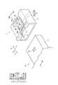
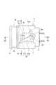
以下、本発明の実施形態を図面に基づいて説明する。図1〜図6は本発明の第1実施形態を示し、図1は第1及び第2コネクタの嵌合前の要部斜視図、図2は第1及び第2コネクタの嵌合状態の平面図、図3は図1のA1−A1線断面図、図4は図3のA2−A2線断面図、図5は図2のB−B線断面図、図6は操作レバーを押下操作した場合のB−B線に沿う断面図である。 Hereinafter, embodiments of the present invention will be described with reference to the drawings. 1 to 6 show a first embodiment of the present invention, FIG. 1 is a perspective view of a main part before the first and second connectors are fitted, and FIG. 2 is a plan view of the fitted state of the first and second connectors. 3 is a cross-sectional view taken along line A1-A1 of FIG. 1, FIG. 4 is a cross-sectional view taken along line A2-A2 of FIG. 3, FIG. 5 is a cross-sectional view taken along line BB of FIG. It is sectional drawing which follows the BB line in the case.
図1及び図2に示すように、第1コネクタ1は、防水コネクタであり、内部に多数の例えばメス端子(図示せず)が収容された第1コネクタハウジング2と、この第1コネクタハウジング2の外側を被うように配置されたコネクタフード部3とを有する。 As shown in FIGS. 1 and 2, the
第2コネクタ10は、防水コネクタであり、内部に多数の例えばオス端子(図示せず)が収容された第2コネクタハウジング11を有する。 The
第1及び第2コネクタ1,10がコネクタ嵌合されると、対応するメス端子(図示せず)とオス端子(図示せず)同士が電気的に接続されると共に、互いの第1コネクタハウジング2,11内に水が侵入しないように気密が保持された状態で嵌合される。又、第1及び第2コネクタ1,10には、コネクタ嵌合状態をロックするためのロック機構20が設けられている。 When the first and
ロック機構20は、第1コネクタ1側に、コネクタ嵌合方向Nのほぼ直交方向Mに延びる第1アーム部21aと、第1アーム部21aに連結され、コネクタ嵌合方向Nに延びる第2アーム部21bとからL字形状をなし、L字形状の両端側がコネクタフード部3に固定されたロックアーム21と、第1アーム部21aに設けられた係合部と、第2アーム部21bから基端部が延設されるとともに、第1、第2コネクタ1,10が嵌合した状態で、第2コネクタ10へ当接するように突設され、押下操作で解除支点部23aを支点として第2アーム部21bと共に第1アーム部21aを嵌合解除方向(本実施形態では図の上方)に撓ませる解除レバー23とを備えている。この第1実施形態では、係合部は第1アーム部21aにて構成され、コネクタ嵌合時に下記する係合突起部25が突き当たる第1アーム部21aの下面側には傾斜ガイド面22aが形成されている。解除レバー23は、第1アーム部21a及び第2アーム部21bに対して共に斜めに配置され、且つ、解除支点部23aも解除レバー23を斜め方向に上下移動するべく斜めに配置されている。 The
ロック機構20は、第2コネクタ10側に、第2コネクタハウジング11の上面に突設された被係合部である係合突起部26を備えている。係合突起部26は、第1アーム部21aのコネクタフード部3との固定箇所から第2アーム部21bとの連結箇所に向かって徐々に高くなるよう設定されている。本実施形態では、図5に示すように、第1アーム部21aの固定側の高さがh1に、第1アーム部21aの第2アーム部21bとの連結側の高さがh2(h1<h2)に設定されている。 The
上記構成において、第1コネクタ1と第2コネクタ10を嵌合するには、図3に示すように、第1コネクタ1のコネクタフード部3内に第2コネクタ10の第2コネクタハウジング11を挿入する。すると、第1コネクタ1側の第1アーム部21aと第2コネクタ10側の係合突起部25が当接し、この状態より更に挿入力を加えると、第1アーム部21aの傾斜ガイド面22aに係合突起部25が入り込むことによって第1アーム部21aが上方に撓み変形し、係合突起部25をロックアーム21が乗越えることで第2コネクタ11の進入を許容する。第1コネクタ1と第2コネクタ10が嵌合完了位置まで嵌合されると、図4及び図5に示すように、係合突起部25は第1アーム部21aを完全に通り越した位置となり、第1アーム部21aが撓み復帰変形して係合突起部25がコネクタ嵌合方向に対して後方に位置する第1アーム部21aの後縁21cに係合される。これによって、第1コネクタ1と第2コネクタ10間がロック機構20によってロックされる。 In the above configuration, in order to fit the
第1コネクタ1と第2コネクタ10の嵌合を解除するには、図6に示すように、解除レバー23の先端部に設けられた操作部23bを押下する。すると、解除レバー23が解除支点部23aを支点として撓み変形し第2アーム部21bを介して第1アーム部21aを上方に変移し、これによって第1アーム部21aの後縁21cと係合突起部25との係合が解除される。解除レバー23を押下した状態で、第1コネクタ1と第2コネクタ10間を引き離す方向に引っ張ると、ロック機構20のロック力を受けることなく第1及び第2コネクタ1,10間を離脱させることができる。 In order to release the fitting between the
以上、本発明では、ロック機構20のロックアーム21がL字形状に構成されているので、ロック機構20のロック時には第1アーム部21aのみならず第2アーム部21bが共に撓み変形しなければロックが外れることがないため、片持ちのストレート形状のロックアームに較べて強いロック保持力を得ることができる。又、解除レバー23の解除力は第2アーム部21bを介して第1アーム部21aの基端部に作用するため、第2アーム部21bからの撓み変形規制力を受けることなく第1アーム部21aを撓み変形させることができる。以上より、ロック解除操作によるロック解除が確実にでき、しかも、ロック時には所望のロック保持力を確保することができる。 As described above, in the present invention, since the
特に、第1アーム部21aのロック保持力は、基本的にはその長さに依存するため、第1アーム部21aの長さLを短く設定すればするほど強力なロック保持力を確保できる。そして、解除レバー23はてこの原理によって第2アーム部21b及び第1アーム部21aを撓み変形させるため、第1アーム部21aの長さを短くしても解除レバー23によるロック解除が困難になることはなく、確実な解除が可能である。 In particular, the lock holding force of the
この第1実施形態では、係合部は第1アーム部21aの後縁21cであり、被係合部は第1アーム部21aに係合する係合突起部25である。従って、第1アーム部21aに別途係合部を付設する必要がなく、構成の単純化になる。 In the first embodiment, the engaging portion is the
この第1実施形態では、係合突起部25は、第1アーム部21aのコネクタフード部3との固定箇所から第2アーム部21bとの連結箇所に向かって徐々に高くなるよう設定されている。従って、係合突起部25が第1アーム部21aに嵌合する場合には、係合突起部25の最も高い箇所を持って第1アーム部21aと係合するため、確実なロックが可能であり、又、解除レバー23による解除操作で第1アーム部21aを上方に撓み変形させると、係合突起部25がその撓み変形に倣った高さ形状であるため、第1アーム部21aの全体を係合突起部25の最も高い高さまで撓ませる必要がない。以上より、ロック時のロック確実性とロック解除時の解除容易性とを共に満足させることができる。 In the first embodiment, the
この第1実施形態では、解除レバー23は、第1アーム部21a及び第2アーム部21bに対して共に斜めに配置され、且つ、解除支点部23aも解除レバー23を斜め方向に上下移動するべく斜めに配置されている。従って、第1及び第2コネクタ1,10間を離脱させる方向の外力が第1アーム部21aに作用すると、この外力によって第1アーム部21aが上方に持ち上がろうとする。ここで、第1アーム部21aが持ち上がるためには第2アーム部21bのみならず解除レバー23をも解除支点部23aを支点として同時に撓み変形する必要があるため、解除レバー23の撓み変形阻止力によって第1アーム部21aの持ち上がりが未然に防止される。つまり、解除レバー23もロック保持力の向上に寄与する。 In this first embodiment, the
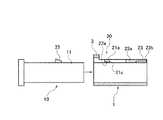
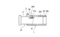
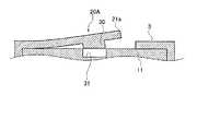
図7〜図12は本発明の第2実施形態を示し、図7は第1及び第2コネクタの嵌合前のロック機構の斜視図、図8は第1及び第2コネクタ間の嵌合状態の平面図、図9は図7のC1−C1線断面図、図10は図8のC2−C2線断面図、図11は図8のD−D線断面図、図12は操作レバーを押下操作した場合のD−D線に沿う断面図である。 7 to 12 show a second embodiment of the present invention, FIG. 7 is a perspective view of a locking mechanism before the first and second connectors are fitted, and FIG. 8 is a fitted state between the first and second connectors. 9 is a sectional view taken along line C1-C1 in FIG. 7, FIG. 10 is a sectional view taken along line C2-C2 in FIG. 8, FIG. 11 is a sectional view taken along line DD in FIG. It is sectional drawing which follows the DD line | wire when operated.
図7〜図12に示すように、この第2実施形態では、前記第1実施形態と較べて、ロック機構20Aの構成が一部相違する。つまり、第1コネクタ1側の係合部は、第1アーム部21aの下面に突設された係合突起部30にて構成されている。第2コネクタ10側の被係合部は、第2コネクタハウジング11の上面に開口された係合孔31にて構成されている。 As shown in FIGS. 7-12, in this 2nd Embodiment, compared with the said 1st Embodiment, the structure of 20 A of lock mechanisms is partially different. That is, the engaging portion on the
ロック機構20Aの他の構成及びロック機構20A以外の構成は、前記第1実施形態と同様であるため、図面の同一構成箇所には同一符号を付してその説明を省略する。 The other configuration of the
上記構成において、第1コネクタ1と第2コネクタ10を嵌合するには、図9に示すように、第1コネクタ1のコネクタフード部3内に第2コネクタ10の第2コネクタハウジング11を挿入する。すると、第1コネクタ1側の第1アーム部21aの係合突起部30と第2コネクタ10側の第2コネクタハウジング11の先端面が当接し、この状態より更に挿入力を加えると、第1アーム部21aが上方に撓み変形して第2コネクタ10の第2コネクタハウジング11の進入を許容する。第1コネクタ1と第2コネクタ10が嵌合完了位置まで嵌合されると、図10及び図11に示すように、第1アーム部21aの係合突起部30が第2コネクタ10の係合孔31の上方位置となり、第1アーム部21aが撓み復帰変形して係合突起部30が係合孔31に係合される。これによって、第1コネクタ1と第2コネクタ10間がロック機構20Aによってロックされる。 In the above configuration, to fit the
第1コネクタと第2コネクタの嵌合を解除するには、図12に示すように、解除レバー23を押下する。すると、解除レバー23が解除支点部23aを支点として撓み変形し第2アーム部21bを介して第1アーム部21aを上方に変移し、これによって第1アーム部21aの係合突起部30と係合孔31との係合が解除される。解除レバー23を押下した状態で、第1コネクタ1と第2コネクタ10間を引き離す方向に引っ張ると、ロック機構20Aのロック力を受けることなく第1及び第2コネクタ1,10間を離脱させることができる。 To release the fitting between the first connector and the second connector, the
以上、ロック機構20Aのロックアーム21がL字形状に構成されているので、ロック機構20Aのロック時には第1アーム部21aのみならず第2アーム部21bが共に撓み変形しなければロックが外れることがないため、片持ちのストレート形状のロックアームに較べて強いロック保持力を得ることができる。又、解除レバー23の解除力は第2アーム部21bを介して第1アーム部21aの先端に作用するため、第2アーム部21bからの撓み変形規制力を受けることなく第1アーム部21aを撓み変形させることができる。以上より、ロック解除操作によるロック解除が確実にでき、しかも、ロック時には所望のロック保持力を確保することができる。 As described above, since the
この第2実施形態では、係合部は第1アーム部21aに付設された係合突起部30であり、被係合部は第2コネクタ10の第2コネクタハウジング11の外周面に開口された係合孔31である。従って、第1コネクタ1にあっては第1アーム部21aの裏面側に係合突起部30が設けられ、第2コネクタ10にあっては第2コネクタハウジング11の外面に係合孔31を開口すれば良いため、第1及び第2コネクタ1,10共に突起箇所が外側に配置されないため、突起箇所による傷付きを防止できる。 In the second embodiment, the engaging portion is an engaging
1…第1コネクタ
10…第2コネクタ
11…第2コネクタハウジング
20…ロック機構
20A…ロック機構
21…ロックアーム
21a…第1アーム部
21b…第2アーム部
21c…後縁(係合部)
23…解除レバー
23a…解除支点部
23b…操作部
25…係合突起部(被係合部)
30…係合突起部(係合部)
31…係合孔(被係合部)
N…コネクタ嵌合方向
M…コネクタ嵌合方向の直交方向DESCRIPTION OF
23 ...
30 ... engaging protrusion (engaging portion)
31 ... engaging hole (engaged part)
N ... Connector fitting direction M ... Direction orthogonal to connector fitting direction
Claims (5)
Translated fromJapanese前記第1コネクタに、
コネクタ嵌合方向のほぼ直交方向に延びる第1アーム部と、
前記第1アーム部に連結され、コネクタ嵌合方向に延びる第2アーム部と、
これら第1アーム部と第2アーム部とによってL字形状に形成され、当該L字形状部分の両端部が固定されたロックアームと、
前記第1アーム部に設けられた係合部と、
前記第2アーム部から基端部分が延設され、先端部分に操作部と、前記第1、第2コネクタが嵌合した状態で、前記第2コネクタへ当接するように突設された解除支点部とを有した解除レバーとを設け、
前記第2コネクタに、
前記第1コネクタとの嵌合完了位置で前記係合部と係合する被係合部を設け、
前記第1コネクタと前記第2コネクタの嵌合途中過程では、前記第1アーム部が撓み変形し、前記被係合部を前記係合部が乗越えることで嵌合完了位置への移動が可能とし、
嵌合完了位置では、前記第1アーム部が撓み変形状態から復帰することによって前記係合部と前記被係合部が係合し、第1及び第2コネクタの嵌合状態がロックされ、
前記操作部を押下操作し、前記解除支点部を支点として前記第1アーム部を係合解除方向に変移させることで、前記係合部と前記被係合部との係合が解除されることを特徴とするコネクタのロック機構。In the connector locking mechanism that holds the fitting state between the first connector and the second connector constituting the connector,
The first connector;
A first arm portion extending in a direction substantially orthogonal to the connector fitting direction;
A second arm connected to the first arm and extending in the connector fitting direction;
A lock arm formed in an L shape by the first arm portion and the second arm portion, and both ends of the L shape portion are fixed,
An engaging portion provided on the first arm portion;
A release fulcrum projecting so as to abut against the second connector in a state in which a base end portion is extended from the second arm portion and an operation portion and the first and second connectors are fitted to a distal end portion. And a release lever having a portion,
The second connector;
An engaged portion that engages with the engaging portion at a fitting completion position with the first connector;
In the course of fitting between the first connector and the second connector, the first arm portion is bent and deformed, and the engagement portion gets over the engaged portion so that it can be moved to a fitting completion position. age,
In the fitting completion position, the engagement portion and the engaged portion are engaged by returning the first arm portion from the bending deformation state, and the fitting state of the first and second connectors is locked,
The engagement between the engagement portion and the engaged portion is released by depressing the operation portion and shifting the first arm portion in the engagement release direction with the release fulcrum portion as a fulcrum. The connector locking mechanism.
前記係合部は、コネクタ嵌合方向に対して後方に位置する前記第1アーム部の後縁で、
前記被係合部は、前記第1アーム部の後縁と係合可能に前記第2コネクタの外周面上に突設された係合突起部であることを特徴とするコネクタのロック機構。A connector locking mechanism according to claim 1,
The engagement portion is a rear edge of the first arm portion located rearward with respect to the connector fitting direction.
The connector locking mechanism, wherein the engaged portion is an engaging protrusion protruding on an outer peripheral surface of the second connector so as to be engageable with a rear edge of the first arm portion.
前記係合部は、前記第1アーム部に前記第2コネクタへ向かって突設された係合突起部で、
前記被係合部は、前記第2コネクタを構成する第2コネクタハウジングの外周面上に開口された係合孔であることを特徴とするコネクタのロック機構。A connector locking mechanism according to claim 1,
The engaging portion is an engaging protrusion protruding from the first arm toward the second connector,
The connector locking mechanism, wherein the engaged portion is an engagement hole opened on an outer peripheral surface of a second connector housing constituting the second connector.
前記係合突起部は、
前記第1アーム部の第1コネクタとの固定箇所から第2アーム部との連結側に向かって徐々に高くなるよう設定されていることを特徴とするコネクタのロック機構。A connector locking mechanism according to claim 2 or claim 3,
The engaging protrusion is
A connector locking mechanism, wherein the locking mechanism is set so as to gradually increase from a portion where the first arm portion is fixed to the first connector toward a connection side with the second arm portion.
前記解除レバーは、
前記第1アーム部及び前記第2アーム部に対して共に斜めに配置され、且つ、前記解除支点部も解除レバーを斜め方向に上下移動するべく斜めに配置されたことを特徴とするコネクタのロック機構。A connector locking mechanism according to any one of claims 1 to 4,
The release lever is
The connector lock characterized in that both the first arm part and the second arm part are arranged obliquely, and the release fulcrum part is also arranged obliquely to move the release lever up and down obliquely. mechanism.
Priority Applications (1)
| Application Number | Priority Date | Filing Date | Title |
|---|---|---|---|
| JP2006277403AJP2008097955A (en) | 2006-10-11 | 2006-10-11 | Connector locking mechanism |
Applications Claiming Priority (1)
| Application Number | Priority Date | Filing Date | Title |
|---|---|---|---|
| JP2006277403AJP2008097955A (en) | 2006-10-11 | 2006-10-11 | Connector locking mechanism |
Publications (1)
| Publication Number | Publication Date |
|---|---|
| JP2008097955Atrue JP2008097955A (en) | 2008-04-24 |
Family
ID=39380589
Family Applications (1)
| Application Number | Title | Priority Date | Filing Date |
|---|---|---|---|
| JP2006277403AAbandonedJP2008097955A (en) | 2006-10-11 | 2006-10-11 | Connector locking mechanism |
Country Status (1)
| Country | Link |
|---|---|
| JP (1) | JP2008097955A (en) |
Cited By (9)
| Publication number | Priority date | Publication date | Assignee | Title |
|---|---|---|---|---|
| CN109562253A (en)* | 2016-08-04 | 2019-04-02 | 尼普洛株式会社 | Needle assembly with valve and indwelling needle assembly |
| JP2019053853A (en)* | 2017-09-13 | 2019-04-04 | 日本圧着端子製造株式会社 | connector |
| JP2021100677A (en)* | 2016-10-05 | 2021-07-08 | ベクトン・ディキンソン・アンド・カンパニーBecton, Dickinson And Company | Septum housing |
| US11571551B2 (en) | 2015-10-28 | 2023-02-07 | Becton, Dickinson And Company | Ergonomic IV systems and methods |
| US11786703B2 (en) | 2015-10-28 | 2023-10-17 | Becton, Dickinson And Company | Closed IV access device with paddle grip needle hub and flash chamber |
| US11964117B2 (en) | 2015-10-28 | 2024-04-23 | Becton, Dickinson And Company | Soft push tabs for catheter adapter |
| US12076509B2 (en) | 2015-10-28 | 2024-09-03 | Becton, Dickinson And Company | Integrated catheter with independent fluid paths |
| US12194254B2 (en) | 2015-10-28 | 2025-01-14 | Becton, Dickinson And Company | Intravenous catheter device with integrated extension tube |
| US12257405B2 (en) | 2015-10-28 | 2025-03-25 | Becton, Dickinson And Company | Ergonomic IV systems and methods |
- 2006
- 2006-10-11JPJP2006277403Apatent/JP2008097955A/ennot_activeAbandoned
Cited By (13)
| Publication number | Priority date | Publication date | Assignee | Title |
|---|---|---|---|---|
| US11964117B2 (en) | 2015-10-28 | 2024-04-23 | Becton, Dickinson And Company | Soft push tabs for catheter adapter |
| US12257405B2 (en) | 2015-10-28 | 2025-03-25 | Becton, Dickinson And Company | Ergonomic IV systems and methods |
| US11571551B2 (en) | 2015-10-28 | 2023-02-07 | Becton, Dickinson And Company | Ergonomic IV systems and methods |
| US12194254B2 (en) | 2015-10-28 | 2025-01-14 | Becton, Dickinson And Company | Intravenous catheter device with integrated extension tube |
| US11786703B2 (en) | 2015-10-28 | 2023-10-17 | Becton, Dickinson And Company | Closed IV access device with paddle grip needle hub and flash chamber |
| US12076509B2 (en) | 2015-10-28 | 2024-09-03 | Becton, Dickinson And Company | Integrated catheter with independent fluid paths |
| JPWO2018026006A1 (en)* | 2016-08-04 | 2019-06-06 | ニプロ株式会社 | Valved needle assembly and indwelling needle assembly |
| CN109562253A (en)* | 2016-08-04 | 2019-04-02 | 尼普洛株式会社 | Needle assembly with valve and indwelling needle assembly |
| JP7174353B2 (en) | 2016-08-04 | 2022-11-17 | ニプロ株式会社 | Valved needle assembly and indwelling needle assembly |
| JP2021100677A (en)* | 2016-10-05 | 2021-07-08 | ベクトン・ディキンソン・アンド・カンパニーBecton, Dickinson And Company | Septum housing |
| US11793986B2 (en) | 2016-10-05 | 2023-10-24 | Becton, Dickinson And Company | Septum housing |
| JP7285875B2 (en) | 2016-10-05 | 2023-06-02 | ベクトン・ディキンソン・アンド・カンパニー | septum housing |
| JP2019053853A (en)* | 2017-09-13 | 2019-04-04 | 日本圧着端子製造株式会社 | connector |
Similar Documents
| Publication | Publication Date | Title |
|---|---|---|
| JP2008097955A (en) | Connector locking mechanism | |
| CN100557896C (en) | Cable connector | |
| JP5289301B2 (en) | Locking cover for electrical connector | |
| US7462070B2 (en) | Connector having lock mechanism | |
| CN114080734B (en) | Connector | |
| US7223114B2 (en) | Connector assembly | |
| CN101488624B (en) | Connector assembly | |
| JP2013097994A (en) | Lever-fitting type connector | |
| JP4575423B2 (en) | connector | |
| JP2008097956A (en) | Connector locking mechanism | |
| JP2013069542A (en) | Connector terminal detaching structure | |
| JP2005183315A (en) | Connector | |
| US7214085B2 (en) | Connector | |
| JP2008128460A (en) | Lock structure | |
| CN101227041B (en) | Connector Locking Mechanism | |
| JP5682066B2 (en) | connector | |
| JP2016115570A (en) | connector | |
| JP4496475B2 (en) | connector | |
| JP4338084B2 (en) | Electrical connector with lock arm | |
| US7458841B2 (en) | Wire cover and a locking construction therefor | |
| JP2005228731A (en) | Electrical connection device | |
| JP3997483B2 (en) | connector | |
| JP5839197B2 (en) | Wiring board connecting device | |
| JP7164492B2 (en) | connector device | |
| JP4813139B2 (en) | Housing lock structure |
Legal Events
| Date | Code | Title | Description |
|---|---|---|---|
| A621 | Written request for application examination | Free format text:JAPANESE INTERMEDIATE CODE: A621 Effective date:20090929 | |
| A762 | Written abandonment of application | Effective date:20101014 Free format text:JAPANESE INTERMEDIATE CODE: A762 |