JP2008093477A - System for placing material into bone - Google Patents
System for placing material into boneDownload PDFInfo
- Publication number
- JP2008093477A JP2008093477AJP2008002534AJP2008002534AJP2008093477AJP 2008093477 AJP2008093477 AJP 2008093477AJP 2008002534 AJP2008002534 AJP 2008002534AJP 2008002534 AJP2008002534 AJP 2008002534AJP 2008093477 AJP2008093477 AJP 2008093477A
- Authority
- JP
- Japan
- Prior art keywords
- instrument
- cannula
- bone
- nozzle
- cavity
- Prior art date
- Legal status (The legal status is an assumption and is not a legal conclusion. Google has not performed a legal analysis and makes no representation as to the accuracy of the status listed.)
- Granted
Links
- 239000000463materialSubstances0.000titleclaimsabstractdescription185
- 210000000988bone and boneAnatomy0.000titleclaimsabstractdescription118
- 238000000034methodMethods0.000claimsabstractdescription47
- 238000007920subcutaneous administrationMethods0.000claimsabstractdescription39
- 210000004872soft tissueAnatomy0.000abstractdescription11
- 238000011049fillingMethods0.000abstractdescription8
- 230000008569processEffects0.000abstractdescription7
- 239000000523sampleSubstances0.000description34
- 230000003073embolic effectEffects0.000description20
- 239000004568cementSubstances0.000description14
- 238000011282treatmentMethods0.000description14
- 230000006870functionEffects0.000description13
- 238000002347injectionMethods0.000description13
- 239000007924injectionSubstances0.000description13
- 210000001519tissueAnatomy0.000description13
- 239000002639bone cementSubstances0.000description12
- 229920003023plasticPolymers0.000description12
- 239000003550markerSubstances0.000description10
- 239000004033plasticSubstances0.000description10
- 230000004044responseEffects0.000description8
- 238000010924continuous productionMethods0.000description7
- 241001422033ThestylusSpecies0.000description6
- 230000001054cortical effectEffects0.000description6
- 206010017076FractureDiseases0.000description5
- 238000005520cutting processMethods0.000description5
- 238000005259measurementMethods0.000description5
- 239000007769metal materialSubstances0.000description5
- 238000003825pressingMethods0.000description5
- 208000010392Bone FracturesDiseases0.000description4
- VTYYLEPIZMXCLO-UHFFFAOYSA-LCalcium carbonateChemical compound[Ca+2].[O-]C([O-])=OVTYYLEPIZMXCLO-UHFFFAOYSA-L0.000description4
- 239000003814drugSubstances0.000description4
- 229940079593drugDrugs0.000description4
- 239000000945fillerSubstances0.000description4
- 239000012530fluidSubstances0.000description4
- -1polyethylenePolymers0.000description4
- 238000004659sterilization and disinfectionMethods0.000description4
- PEDCQBHIVMGVHV-UHFFFAOYSA-NGlycerineChemical compoundOCC(O)COPEDCQBHIVMGVHV-UHFFFAOYSA-N0.000description3
- 239000004698PolyethyleneSubstances0.000description3
- 210000000746body regionAnatomy0.000description3
- 239000000316bone substituteSubstances0.000description3
- 230000006378damageEffects0.000description3
- 239000007788liquidSubstances0.000description3
- 238000002156mixingMethods0.000description3
- 230000037361pathwayEffects0.000description3
- 229920000573polyethylenePolymers0.000description3
- 239000010935stainless steelSubstances0.000description3
- 229910001220stainless steelInorganic materials0.000description3
- 230000001954sterilising effectEffects0.000description3
- 208000020084Bone diseaseDiseases0.000description2
- 241000282412HomoSpecies0.000description2
- 241001465754MetazoaSpecies0.000description2
- 239000004677NylonSubstances0.000description2
- 230000008901benefitEffects0.000description2
- 229910000019calcium carbonateInorganic materials0.000description2
- 239000008187granular materialSubstances0.000description2
- 230000036512infertilityEffects0.000description2
- 238000003780insertionMethods0.000description2
- 230000037431insertionEffects0.000description2
- 229910001000nickel titaniumInorganic materials0.000description2
- 229920001778nylonPolymers0.000description2
- 238000012856packingMethods0.000description2
- 239000008188pelletSubstances0.000description2
- 239000002985plastic filmSubstances0.000description2
- 229920000139polyethylene terephthalatePolymers0.000description2
- 239000005020polyethylene terephthalateSubstances0.000description2
- 229920002635polyurethanePolymers0.000description2
- 239000004814polyurethaneSubstances0.000description2
- 241000242757AnthozoaSpecies0.000description1
- 235000017060Arachis glabrataNutrition0.000description1
- 241001553178Arachis glabrataSpecies0.000description1
- 235000010777Arachis hypogaeaNutrition0.000description1
- 235000018262Arachis monticolaNutrition0.000description1
- 229920002799BoPETPolymers0.000description1
- 241000283690Bos taurusSpecies0.000description1
- 235000014653Carica parvifloraNutrition0.000description1
- 102000008186CollagenHuman genes0.000description1
- 108010035532CollagenProteins0.000description1
- NNJVILVZKWQKPM-UHFFFAOYSA-NLidocaineChemical compoundCCN(CC)CC(=O)NC1=C(C)C=CC=C1CNNJVILVZKWQKPM-UHFFFAOYSA-N0.000description1
- 208000001132OsteoporosisDiseases0.000description1
- FAPWRFPIFSIZLT-UHFFFAOYSA-MSodium chlorideChemical compound[Na+].[Cl-]FAPWRFPIFSIZLT-UHFFFAOYSA-M0.000description1
- 239000004775TyvekSubstances0.000description1
- 229920000690TyvekPolymers0.000description1
- 208000027418Wounds and injuryDiseases0.000description1
- HZEWFHLRYVTOIW-UHFFFAOYSA-N[Ti].[Ni]Chemical compound[Ti].[Ni]HZEWFHLRYVTOIW-UHFFFAOYSA-N0.000description1
- 238000005299abrasionMethods0.000description1
- 230000009471actionEffects0.000description1
- 230000003213activating effectEffects0.000description1
- 230000000735allogeneic effectEffects0.000description1
- 229910045601alloyInorganic materials0.000description1
- 239000000956alloySubstances0.000description1
- 230000003444anaesthetic effectEffects0.000description1
- 210000002805bone matrixAnatomy0.000description1
- 235000014121butterNutrition0.000description1
- 239000001506calcium phosphateSubstances0.000description1
- 229910000389calcium phosphateInorganic materials0.000description1
- 235000011010calcium phosphatesNutrition0.000description1
- 230000008859changeEffects0.000description1
- 210000000038chestAnatomy0.000description1
- 239000011248coating agentSubstances0.000description1
- 238000000576coating methodMethods0.000description1
- 229920001436collagenPolymers0.000description1
- 238000004891communicationMethods0.000description1
- 230000006835compressionEffects0.000description1
- 238000007906compressionMethods0.000description1
- 238000002591computed tomographyMethods0.000description1
- 239000002872contrast mediaSubstances0.000description1
- 230000008878couplingEffects0.000description1
- 238000010168coupling processMethods0.000description1
- 238000005859coupling reactionMethods0.000description1
- 230000003111delayed effectEffects0.000description1
- 238000000280densificationMethods0.000description1
- 238000007599dischargingMethods0.000description1
- 201000010099diseaseDiseases0.000description1
- 208000037265diseases, disorders, signs and symptomsDiseases0.000description1
- 238000012377drug deliveryMethods0.000description1
- 230000010102embolizationEffects0.000description1
- 238000002594fluoroscopyMethods0.000description1
- 238000007373indentationMethods0.000description1
- 208000014674injuryDiseases0.000description1
- 229920000554ionomerPolymers0.000description1
- 229960004194lidocaineDrugs0.000description1
- 238000011068loading methodMethods0.000description1
- 238000002690local anesthesiaMethods0.000description1
- 238000002595magnetic resonance imagingMethods0.000description1
- 238000004519manufacturing processMethods0.000description1
- 230000007246mechanismEffects0.000description1
- 229910001092metal group alloyInorganic materials0.000description1
- 239000002991molded plasticSubstances0.000description1
- 238000012544monitoring processMethods0.000description1
- HLXZNVUGXRDIFK-UHFFFAOYSA-Nnickel titaniumChemical compound[Ti].[Ti].[Ti].[Ti].[Ti].[Ti].[Ti].[Ti].[Ti].[Ti].[Ti].[Ni].[Ni].[Ni].[Ni].[Ni].[Ni].[Ni].[Ni].[Ni].[Ni].[Ni].[Ni].[Ni].[Ni]HLXZNVUGXRDIFK-UHFFFAOYSA-N0.000description1
- 230000000399orthopedic effectEffects0.000description1
- 235000020232peanutNutrition0.000description1
- 230000000149penetrating effectEffects0.000description1
- 230000035515penetrationEffects0.000description1
- 230000004962physiological conditionEffects0.000description1
- 229920000642polymerPolymers0.000description1
- 229920001296polysiloxanePolymers0.000description1
- 239000000843powderSubstances0.000description1
- 238000002360preparation methodMethods0.000description1
- 230000005855radiationEffects0.000description1
- 230000009467reductionEffects0.000description1
- 238000009958sewingMethods0.000description1
- 239000011780sodium chlorideSubstances0.000description1
- 210000000278spinal cordAnatomy0.000description1
- 238000003860storageMethods0.000description1
- 239000000126substanceSubstances0.000description1
- 238000003856thermoformingMethods0.000description1
- QORWJWZARLRLPR-UHFFFAOYSA-Htricalcium bis(phosphate)Chemical compound[Ca+2].[Ca+2].[Ca+2].[O-]P([O-])([O-])=O.[O-]P([O-])([O-])=OQORWJWZARLRLPR-UHFFFAOYSA-H0.000description1
- 125000000391vinyl groupChemical group[H]C([*])=C([H])[H]0.000description1
- 229920002554vinyl polymerPolymers0.000description1
- 239000011345viscous materialSubstances0.000description1
- 238000012800visualizationMethods0.000description1
Images


Classifications
- A—HUMAN NECESSITIES
- A61—MEDICAL OR VETERINARY SCIENCE; HYGIENE
- A61F—FILTERS IMPLANTABLE INTO BLOOD VESSELS; PROSTHESES; DEVICES PROVIDING PATENCY TO, OR PREVENTING COLLAPSING OF, TUBULAR STRUCTURES OF THE BODY, e.g. STENTS; ORTHOPAEDIC, NURSING OR CONTRACEPTIVE DEVICES; FOMENTATION; TREATMENT OR PROTECTION OF EYES OR EARS; BANDAGES, DRESSINGS OR ABSORBENT PADS; FIRST-AID KITS
- A61F2/00—Filters implantable into blood vessels; Prostheses, i.e. artificial substitutes or replacements for parts of the body; Appliances for connecting them with the body; Devices providing patency to, or preventing collapsing of, tubular structures of the body, e.g. stents
- A61F2/02—Prostheses implantable into the body
- A61F2/30—Joints
- A61F2/46—Special tools for implanting artificial joints
- A61F2/4601—Special tools for implanting artificial joints for introducing bone substitute, for implanting bone graft implants or for compacting them in the bone cavity
- A—HUMAN NECESSITIES
- A61—MEDICAL OR VETERINARY SCIENCE; HYGIENE
- A61B—DIAGNOSIS; SURGERY; IDENTIFICATION
- A61B17/00—Surgical instruments, devices or methods
- A61B17/56—Surgical instruments or methods for treatment of bones or joints; Devices specially adapted therefor
- A61B17/58—Surgical instruments or methods for treatment of bones or joints; Devices specially adapted therefor for osteosynthesis, e.g. bone plates, screws or setting implements
- A61B17/88—Osteosynthesis instruments; Methods or means for implanting or extracting internal or external fixation devices
- A61B17/8802—Equipment for handling bone cement or other fluid fillers
- A61B17/8805—Equipment for handling bone cement or other fluid fillers for introducing fluid filler into bone or extracting it
- A61B17/8816—Equipment for handling bone cement or other fluid fillers for introducing fluid filler into bone or extracting it characterised by the conduit, e.g. tube, along which fluid flows into the body or by conduit connections
- A—HUMAN NECESSITIES
- A61—MEDICAL OR VETERINARY SCIENCE; HYGIENE
- A61B—DIAGNOSIS; SURGERY; IDENTIFICATION
- A61B17/00—Surgical instruments, devices or methods
- A61B17/56—Surgical instruments or methods for treatment of bones or joints; Devices specially adapted therefor
- A61B17/58—Surgical instruments or methods for treatment of bones or joints; Devices specially adapted therefor for osteosynthesis, e.g. bone plates, screws or setting implements
- A61B17/88—Osteosynthesis instruments; Methods or means for implanting or extracting internal or external fixation devices
- A61B17/8802—Equipment for handling bone cement or other fluid fillers
- A61B17/8805—Equipment for handling bone cement or other fluid fillers for introducing fluid filler into bone or extracting it
- A61B17/8822—Equipment for handling bone cement or other fluid fillers for introducing fluid filler into bone or extracting it characterised by means facilitating expulsion of fluid from the introducer, e.g. a screw pump plunger, hydraulic force transmissions, application of vibrations or a vacuum
- A—HUMAN NECESSITIES
- A61—MEDICAL OR VETERINARY SCIENCE; HYGIENE
- A61B—DIAGNOSIS; SURGERY; IDENTIFICATION
- A61B17/00—Surgical instruments, devices or methods
- A61B17/56—Surgical instruments or methods for treatment of bones or joints; Devices specially adapted therefor
- A61B17/58—Surgical instruments or methods for treatment of bones or joints; Devices specially adapted therefor for osteosynthesis, e.g. bone plates, screws or setting implements
- A61B17/88—Osteosynthesis instruments; Methods or means for implanting or extracting internal or external fixation devices
- A61B17/8802—Equipment for handling bone cement or other fluid fillers
- A61B17/8833—Osteosynthesis tools specially adapted for handling bone cement or fluid fillers; Means for supplying bone cement or fluid fillers to introducing tools, e.g. cartridge handling means
- A—HUMAN NECESSITIES
- A61—MEDICAL OR VETERINARY SCIENCE; HYGIENE
- A61B—DIAGNOSIS; SURGERY; IDENTIFICATION
- A61B17/00—Surgical instruments, devices or methods
- A61B17/56—Surgical instruments or methods for treatment of bones or joints; Devices specially adapted therefor
- A61B17/58—Surgical instruments or methods for treatment of bones or joints; Devices specially adapted therefor for osteosynthesis, e.g. bone plates, screws or setting implements
- A61B17/88—Osteosynthesis instruments; Methods or means for implanting or extracting internal or external fixation devices
- A61B17/885—Tools for expanding or compacting bones or discs or cavities therein
- A61B17/8852—Tools for expanding or compacting bones or discs or cavities therein capable of being assembled or enlarged, or changing shape, inside the bone or disc
- A61B17/8855—Tools for expanding or compacting bones or discs or cavities therein capable of being assembled or enlarged, or changing shape, inside the bone or disc inflatable, e.g. kyphoplasty balloons
- A—HUMAN NECESSITIES
- A61—MEDICAL OR VETERINARY SCIENCE; HYGIENE
- A61B—DIAGNOSIS; SURGERY; IDENTIFICATION
- A61B17/00—Surgical instruments, devices or methods
- A61B17/16—Instruments for performing osteoclasis; Drills or chisels for bones; Trepans
- A61B17/1662—Instruments for performing osteoclasis; Drills or chisels for bones; Trepans for particular parts of the body
- A61B17/1671—Instruments for performing osteoclasis; Drills or chisels for bones; Trepans for particular parts of the body for the spine
- A—HUMAN NECESSITIES
- A61—MEDICAL OR VETERINARY SCIENCE; HYGIENE
- A61B—DIAGNOSIS; SURGERY; IDENTIFICATION
- A61B17/00—Surgical instruments, devices or methods
- A61B17/34—Trocars; Puncturing needles
- A61B17/3472—Trocars; Puncturing needles for bones, e.g. intraosseus injections
- A—HUMAN NECESSITIES
- A61—MEDICAL OR VETERINARY SCIENCE; HYGIENE
- A61B—DIAGNOSIS; SURGERY; IDENTIFICATION
- A61B17/00—Surgical instruments, devices or methods
- A61B17/56—Surgical instruments or methods for treatment of bones or joints; Devices specially adapted therefor
- A61B17/58—Surgical instruments or methods for treatment of bones or joints; Devices specially adapted therefor for osteosynthesis, e.g. bone plates, screws or setting implements
- A61B17/68—Internal fixation devices, including fasteners and spinal fixators, even if a part thereof projects from the skin
- A61B17/70—Spinal positioners or stabilisers, e.g. stabilisers comprising fluid filler in an implant
- A61B17/7097—Stabilisers comprising fluid filler in an implant, e.g. balloon; devices for inserting or filling such implants
- A—HUMAN NECESSITIES
- A61—MEDICAL OR VETERINARY SCIENCE; HYGIENE
- A61B—DIAGNOSIS; SURGERY; IDENTIFICATION
- A61B17/00—Surgical instruments, devices or methods
- A61B17/56—Surgical instruments or methods for treatment of bones or joints; Devices specially adapted therefor
- A61B17/58—Surgical instruments or methods for treatment of bones or joints; Devices specially adapted therefor for osteosynthesis, e.g. bone plates, screws or setting implements
- A61B17/88—Osteosynthesis instruments; Methods or means for implanting or extracting internal or external fixation devices
- A61B17/8802—Equipment for handling bone cement or other fluid fillers
- A61B17/8805—Equipment for handling bone cement or other fluid fillers for introducing fluid filler into bone or extracting it
- A—HUMAN NECESSITIES
- A61—MEDICAL OR VETERINARY SCIENCE; HYGIENE
- A61B—DIAGNOSIS; SURGERY; IDENTIFICATION
- A61B17/00—Surgical instruments, devices or methods
- A61B17/00234—Surgical instruments, devices or methods for minimally invasive surgery
- A61B2017/00238—Type of minimally invasive operation
- A61B2017/00261—Discectomy
- A—HUMAN NECESSITIES
- A61—MEDICAL OR VETERINARY SCIENCE; HYGIENE
- A61B—DIAGNOSIS; SURGERY; IDENTIFICATION
- A61B17/00—Surgical instruments, devices or methods
- A61B2017/0046—Surgical instruments, devices or methods with a releasable handle; with handle and operating part separable
- A61B2017/00464—Surgical instruments, devices or methods with a releasable handle; with handle and operating part separable for use with different instruments
- A—HUMAN NECESSITIES
- A61—MEDICAL OR VETERINARY SCIENCE; HYGIENE
- A61B—DIAGNOSIS; SURGERY; IDENTIFICATION
- A61B17/00—Surgical instruments, devices or methods
- A61B2017/00831—Material properties
- A61B2017/00867—Material properties shape memory effect
- A—HUMAN NECESSITIES
- A61—MEDICAL OR VETERINARY SCIENCE; HYGIENE
- A61B—DIAGNOSIS; SURGERY; IDENTIFICATION
- A61B50/00—Containers, covers, furniture or holders specially adapted for surgical or diagnostic appliances or instruments, e.g. sterile covers
- A61B2050/005—Containers, covers, furniture or holders specially adapted for surgical or diagnostic appliances or instruments, e.g. sterile covers with a lid or cover
- A61B2050/0065—Peelable cover
- A—HUMAN NECESSITIES
- A61—MEDICAL OR VETERINARY SCIENCE; HYGIENE
- A61B—DIAGNOSIS; SURGERY; IDENTIFICATION
- A61B90/00—Instruments, implements or accessories specially adapted for surgery or diagnosis and not covered by any of the groups A61B1/00 - A61B50/00, e.g. for luxation treatment or for protecting wound edges
- A61B90/06—Measuring instruments not otherwise provided for
- A61B2090/062—Measuring instruments not otherwise provided for penetration depth
- A—HUMAN NECESSITIES
- A61—MEDICAL OR VETERINARY SCIENCE; HYGIENE
- A61B—DIAGNOSIS; SURGERY; IDENTIFICATION
- A61B50/00—Containers, covers, furniture or holders specially adapted for surgical or diagnostic appliances or instruments, e.g. sterile covers
- A61B50/30—Containers specially adapted for packaging, protecting, dispensing, collecting or disposing of surgical or diagnostic appliances or instruments
- A61B50/33—Trays
- A—HUMAN NECESSITIES
- A61—MEDICAL OR VETERINARY SCIENCE; HYGIENE
- A61B—DIAGNOSIS; SURGERY; IDENTIFICATION
- A61B90/00—Instruments, implements or accessories specially adapted for surgery or diagnosis and not covered by any of the groups A61B1/00 - A61B50/00, e.g. for luxation treatment or for protecting wound edges
- A61B90/39—Markers, e.g. radio-opaque or breast lesions markers
- A—HUMAN NECESSITIES
- A61—MEDICAL OR VETERINARY SCIENCE; HYGIENE
- A61F—FILTERS IMPLANTABLE INTO BLOOD VESSELS; PROSTHESES; DEVICES PROVIDING PATENCY TO, OR PREVENTING COLLAPSING OF, TUBULAR STRUCTURES OF THE BODY, e.g. STENTS; ORTHOPAEDIC, NURSING OR CONTRACEPTIVE DEVICES; FOMENTATION; TREATMENT OR PROTECTION OF EYES OR EARS; BANDAGES, DRESSINGS OR ABSORBENT PADS; FIRST-AID KITS
- A61F2/00—Filters implantable into blood vessels; Prostheses, i.e. artificial substitutes or replacements for parts of the body; Appliances for connecting them with the body; Devices providing patency to, or preventing collapsing of, tubular structures of the body, e.g. stents
- A61F2/02—Prostheses implantable into the body
- A61F2/30—Joints
- A61F2/44—Joints for the spine, e.g. vertebrae, spinal discs
- A—HUMAN NECESSITIES
- A61—MEDICAL OR VETERINARY SCIENCE; HYGIENE
- A61F—FILTERS IMPLANTABLE INTO BLOOD VESSELS; PROSTHESES; DEVICES PROVIDING PATENCY TO, OR PREVENTING COLLAPSING OF, TUBULAR STRUCTURES OF THE BODY, e.g. STENTS; ORTHOPAEDIC, NURSING OR CONTRACEPTIVE DEVICES; FOMENTATION; TREATMENT OR PROTECTION OF EYES OR EARS; BANDAGES, DRESSINGS OR ABSORBENT PADS; FIRST-AID KITS
- A61F2/00—Filters implantable into blood vessels; Prostheses, i.e. artificial substitutes or replacements for parts of the body; Appliances for connecting them with the body; Devices providing patency to, or preventing collapsing of, tubular structures of the body, e.g. stents
- A61F2/02—Prostheses implantable into the body
- A61F2/30—Joints
- A61F2/46—Special tools for implanting artificial joints
- A61F2/4603—Special tools for implanting artificial joints for insertion or extraction of endoprosthetic joints or of accessories thereof
- A—HUMAN NECESSITIES
- A61—MEDICAL OR VETERINARY SCIENCE; HYGIENE
- A61F—FILTERS IMPLANTABLE INTO BLOOD VESSELS; PROSTHESES; DEVICES PROVIDING PATENCY TO, OR PREVENTING COLLAPSING OF, TUBULAR STRUCTURES OF THE BODY, e.g. STENTS; ORTHOPAEDIC, NURSING OR CONTRACEPTIVE DEVICES; FOMENTATION; TREATMENT OR PROTECTION OF EYES OR EARS; BANDAGES, DRESSINGS OR ABSORBENT PADS; FIRST-AID KITS
- A61F2/00—Filters implantable into blood vessels; Prostheses, i.e. artificial substitutes or replacements for parts of the body; Appliances for connecting them with the body; Devices providing patency to, or preventing collapsing of, tubular structures of the body, e.g. stents
- A61F2/02—Prostheses implantable into the body
- A61F2/28—Bones
- A61F2002/2835—Bone graft implants for filling a bony defect or an endoprosthesis cavity, e.g. by synthetic material or biological material
- A—HUMAN NECESSITIES
- A61—MEDICAL OR VETERINARY SCIENCE; HYGIENE
- A61F—FILTERS IMPLANTABLE INTO BLOOD VESSELS; PROSTHESES; DEVICES PROVIDING PATENCY TO, OR PREVENTING COLLAPSING OF, TUBULAR STRUCTURES OF THE BODY, e.g. STENTS; ORTHOPAEDIC, NURSING OR CONTRACEPTIVE DEVICES; FOMENTATION; TREATMENT OR PROTECTION OF EYES OR EARS; BANDAGES, DRESSINGS OR ABSORBENT PADS; FIRST-AID KITS
- A61F2/00—Filters implantable into blood vessels; Prostheses, i.e. artificial substitutes or replacements for parts of the body; Appliances for connecting them with the body; Devices providing patency to, or preventing collapsing of, tubular structures of the body, e.g. stents
- A61F2/02—Prostheses implantable into the body
- A61F2/30—Joints
- A61F2002/30001—Additional features of subject-matter classified in A61F2/28, A61F2/30 and subgroups thereof
- A61F2002/30003—Material related properties of the prosthesis or of a coating on the prosthesis
- A61F2002/3006—Properties of materials and coating materials
- A61F2002/3008—Properties of materials and coating materials radio-opaque, e.g. radio-opaque markers
- A—HUMAN NECESSITIES
- A61—MEDICAL OR VETERINARY SCIENCE; HYGIENE
- A61F—FILTERS IMPLANTABLE INTO BLOOD VESSELS; PROSTHESES; DEVICES PROVIDING PATENCY TO, OR PREVENTING COLLAPSING OF, TUBULAR STRUCTURES OF THE BODY, e.g. STENTS; ORTHOPAEDIC, NURSING OR CONTRACEPTIVE DEVICES; FOMENTATION; TREATMENT OR PROTECTION OF EYES OR EARS; BANDAGES, DRESSINGS OR ABSORBENT PADS; FIRST-AID KITS
- A61F2/00—Filters implantable into blood vessels; Prostheses, i.e. artificial substitutes or replacements for parts of the body; Appliances for connecting them with the body; Devices providing patency to, or preventing collapsing of, tubular structures of the body, e.g. stents
- A61F2/02—Prostheses implantable into the body
- A61F2/30—Joints
- A61F2/46—Special tools for implanting artificial joints
- A61F2/4657—Measuring instruments used for implanting artificial joints
- A61F2002/4662—Measuring instruments used for implanting artificial joints for measuring penetration depth
- A—HUMAN NECESSITIES
- A61—MEDICAL OR VETERINARY SCIENCE; HYGIENE
- A61F—FILTERS IMPLANTABLE INTO BLOOD VESSELS; PROSTHESES; DEVICES PROVIDING PATENCY TO, OR PREVENTING COLLAPSING OF, TUBULAR STRUCTURES OF THE BODY, e.g. STENTS; ORTHOPAEDIC, NURSING OR CONTRACEPTIVE DEVICES; FOMENTATION; TREATMENT OR PROTECTION OF EYES OR EARS; BANDAGES, DRESSINGS OR ABSORBENT PADS; FIRST-AID KITS
- A61F2250/00—Special features of prostheses classified in groups A61F2/00 - A61F2/26 or A61F2/82 or A61F9/00 or A61F11/00 or subgroups thereof
- A61F2250/0058—Additional features; Implant or prostheses properties not otherwise provided for
- A61F2250/0096—Markers and sensors for detecting a position or changes of a position of an implant, e.g. RF sensors, ultrasound markers
- A61F2250/0098—Markers and sensors for detecting a position or changes of a position of an implant, e.g. RF sensors, ultrasound markers radio-opaque, e.g. radio-opaque markers
- A—HUMAN NECESSITIES
- A61—MEDICAL OR VETERINARY SCIENCE; HYGIENE
- A61F—FILTERS IMPLANTABLE INTO BLOOD VESSELS; PROSTHESES; DEVICES PROVIDING PATENCY TO, OR PREVENTING COLLAPSING OF, TUBULAR STRUCTURES OF THE BODY, e.g. STENTS; ORTHOPAEDIC, NURSING OR CONTRACEPTIVE DEVICES; FOMENTATION; TREATMENT OR PROTECTION OF EYES OR EARS; BANDAGES, DRESSINGS OR ABSORBENT PADS; FIRST-AID KITS
- A61F2310/00—Prostheses classified in A61F2/28 or A61F2/30 - A61F2/44 being constructed from or coated with a particular material
- A61F2310/00005—The prosthesis being constructed from a particular material
- A61F2310/00353—Bone cement, e.g. polymethylmethacrylate or PMMA
Landscapes
- Health & Medical Sciences (AREA)
- Life Sciences & Earth Sciences (AREA)
- Orthopedic Medicine & Surgery (AREA)
- Surgery (AREA)
- Public Health (AREA)
- Engineering & Computer Science (AREA)
- Biomedical Technology (AREA)
- Heart & Thoracic Surgery (AREA)
- Animal Behavior & Ethology (AREA)
- General Health & Medical Sciences (AREA)
- Veterinary Medicine (AREA)
- Medical Informatics (AREA)
- Molecular Biology (AREA)
- Nuclear Medicine, Radiotherapy & Molecular Imaging (AREA)
- Transplantation (AREA)
- Oral & Maxillofacial Surgery (AREA)
- Physics & Mathematics (AREA)
- Physical Education & Sports Medicine (AREA)
- Cardiology (AREA)
- Fluid Mechanics (AREA)
- Vascular Medicine (AREA)
- Neurology (AREA)
- Pathology (AREA)
- Dentistry (AREA)
- Surgical Instruments (AREA)
- Prostheses (AREA)
- Materials For Medical Uses (AREA)
- Pharmaceuticals Containing Other Organic And Inorganic Compounds (AREA)
- Apparatus For Radiation Diagnosis (AREA)
Abstract
Description
Translated fromJapanese(発明の分野)
本発明は、一般に、ヒトおよび他の動物の骨疾患の処置に関する。(Field of Invention)
The present invention relates generally to the treatment of bone diseases in humans and other animals.
(発明の背景)
骨セメントを骨に注入するために、家庭用コーキングガン(cauling gun)に類似した注入装置が使用されている。典型的な骨セメント注入装置は、ピストル形状の本体を有し、これは、骨セメントを含有するカートリッジを支持している。トリガーがバネ装填ラムを作動して、粘稠状態にある一定容量の骨セメントを、適当なノズルを通って、処置の標的となっている骨の内部に押し込む。特許文献1および特許文献2の教示によると、この骨の内部の海綿質(そこに、この骨セメントが注入される)を圧迫することにより、まず、空洞が形成される。従来のセメント注入装置は、このバネ作動装填サイクルが完了する前にこの空洞が満たされたら、このバネ作用を無効にしてセメントの流れを迅速に停止する機会を与えない。さらに、一旦、このバネ作動機構が起こると、従来のセメント注入装置では、骨の内部で遭遇する海綿質の容量および密度状態に反応して、リアルタイムで、その注入容量および注入速度を調整または制御できない。脊椎形成術(vertebroplasty)と呼ばれる臨床的な処置では、骨セメントは、空洞を先に形成することなく、高圧(典型的には、約700psi)で、椎体の内部に注入される。高圧を使用するので、遭遇する骨の容量および密度状態に反応してセメントの流れを迅速かつ正確に調整する機会は殆どない。高圧で誘発したセメント流れにより発生される運動量は、この高圧を停止した後でも、セメントを標的骨部位へと推進し続ける。(Background of the Invention)
An injection device similar to a home caulking gun has been used to inject bone cement into bone. A typical bone cement injector has a pistol-shaped body that supports a cartridge containing bone cement. A trigger activates a spring loaded ram to push a volume of bone cement in a viscous state through the appropriate nozzle into the bone being targeted for treatment. According to the teachings ofPatent Document 1 andPatent Document 2 , a cavity is first formed by squeezing cancellous material (in which bone cement is injected) into the bone. Conventional cement injectors do not give the opportunity to quickly stop the cement flow by disabling the spring action if the cavity is filled before the spring loaded cycle is completed. In addition, once this spring actuation mechanism occurs, conventional cement injectors adjust or control the injection volume and rate in real time in response to the cancellous volume and density conditions encountered within the bone. Can not. In a clinical procedure called vertebraplasty, bone cement is injected into the vertebral body at high pressure (typically about 700 psi) without first forming a cavity. Because of the use of high pressure, there is little opportunity to adjust the cement flow quickly and accurately in response to the bone volume and density conditions encountered. The momentum generated by the high pressure-induced cement flow continues to push the cement to the target bone site even after the high pressure is stopped.
従来の処置が比較的高い圧力に頼っている結果として、短い応答時間が事実上欠けていることと連関して、標的骨の内部は、突然一杯になり得る。過剰な充填材料は、骨の内部から外に出て、隣接している組織領域(この領域では、充填材料が存在している必要がないか、または、その存在は望ましくない)に入ることを余儀なくされ得る。
これらの理由および他の理由のために、さらに大きな速度および容量の制御、より速い応答時間で、高圧を使用する必要なしに、材料を骨に配置する新しいシステムおよび方法が必要とされている。 For these and other reasons, there is a need for new systems and methods for placing material in bone without the need to use high pressure with greater speed and volume control, faster response times.
(発明の要旨)
本発明は、使用中、骨への材料の配置をさらに大きく制御できるようにする器具、システムおよび方法を提供する。(Summary of the Invention)
The present invention provides instruments, systems and methods that allow greater control over the placement of material on bone during use.
本発明の1局面は、皮下経路を通って骨に材料を詰めるための器具を提供する。この器具は、一定長さおよび終端を有する本体を備える。この本体は、刻印を備え、この刻印は、この終端から増大した長さに沿って、位置している。この刻印により、医師は、材料が骨に充填される場合、この皮下経路にあるこの器具の位置を測ることが可能になる。特に、これらのマーカーにより、医師は、この終端の位置を一瞥して、この皮下経路の末端から材料がどの程度越えているかまたは足りないかについて、知ることができるようになる。 One aspect of the present invention provides an instrument for packing material into bone through a subcutaneous route. The instrument comprises a body having a constant length and a terminal end. The body comprises an inscription, which is located along an increased length from this end. This inscription allows the physician to measure the position of the instrument in the subcutaneous path when material is filled into the bone. In particular, these markers allow the physician to take a glance at the location of this termination and know how much material is missing or missing from the end of this subcutaneous pathway.
1実施態様では、この器具は、カニューレを展開して骨への皮下経路を確立するために使用される。このカニューレを通って、材料が骨に導入される。この器具の終端は、このカニューレを通って前進され、カニューレ内に存在している材料を骨に押し付ける。 In one embodiment, the instrument is used to deploy a cannula to establish a subcutaneous route to the bone. Through this cannula, material is introduced into the bone. The end of the instrument is advanced through the cannula and presses the material present in the cannula against the bone.
本発明の他の局面は、皮下経路を通して骨に材料を導入するための装置を提供する。この装置は、低い送達圧力でこの材料を運搬する送達装置を備える。本明細書中で使用する「低い送達圧力」との用語は、その注射器ピストンに適度の力を加えることにより1cc注射器から液体が出る力と同等であり、それは、約360psi以下の圧力に等しくなる。 Another aspect of the invention provides a device for introducing material into bone through the subcutaneous route. The device comprises a delivery device that carries the material at a low delivery pressure. As used herein, the term “low delivery pressure” is equivalent to the force of liquid coming out of a 1 cc syringe by applying a moderate force to its syringe piston, which is equal to a pressure of about 360 psi or less. .
本発明のこの局面によれば、この装置はまた、ノズル器具を備え、このノズル器具は、この皮下カニューレを通って、骨へと前進できる。このノズルは、近位取付具を備え、この近位取付具は、このノズル器具を送達装置に連結するためにある。このノズルは、さらに、ノズル終端を備え、このノズル終端を通って、この送達装置により運搬される材料は、この送達圧力で、骨に入る。 According to this aspect of the invention, the device also includes a nozzle device that can be advanced through the subcutaneous cannula and into the bone. The nozzle includes a proximal fitting that is for coupling the nozzle device to a delivery device. The nozzle further comprises a nozzle end through which material carried by the delivery device enters the bone at the delivery pressure.
1実施態様では、この送達装置は、注射器を備える。 In one embodiment, the delivery device comprises a syringe.
1実施態様では、この装置は、さらに、タンピング器具を備え、これは、この皮下カニューレを通って前進できる。このタンピング器具は、タンピング終端を有し、この充填終端は、この前進中にて、この皮下カニューレ内に存在している材料を骨に押し付ける。 In one embodiment, the device further comprises a tamping instrument that can be advanced through the subcutaneous cannula. The tamping instrument has a tamping end that, during the advancement, presses the material present in the subcutaneous cannula against the bone.
1実施態様では、このタンピング器具は、刻印を有し、この刻印は、この皮下カニューレを通るタンピング終端の前進を視覚的に測るためにある。 In one embodiment, the tamping instrument has a stamp, which is for visually measuring the advancement of the tamping end through the subcutaneous cannula.
1実施態様では、この装置は、カニューレを展開して骨への皮下経路を確立することにより、使用される。この送達装置は、作動されて、この送達圧力で、このノズル終端を通って、骨へと材料を運搬する。 In one embodiment, the device is used by deploying a cannula to establish a subcutaneous route to the bone. The delivery device is activated to carry material at the delivery pressure through the nozzle end to the bone.
本発明の他の局面は、骨に展開するための用具を提供する。この用具は、カテーテルチューブおよび拡大可能構造体を備え、このカテーテルチューブは、遠位領域を有し、そしてこの拡大可能構造体は、海綿質を緻密化するために、この遠位領域により運ばれる。この用具はまた、導入器スリーブを備え、この導入器スリーブは、後退位置と前進位置との間で移動するために、このカテーテルチューブにより滑り可能に運ばれ、この後退位置は、この拡大可能構造体から間隔が開けられ、そしてこの前進位置は、拡大可能構造体の上に重なる。この導入器スリーブは、管状本体を備え、この管状本体は、導入器スリーブが前進位置にあるとき、この拡大可能構造体を圧迫するような寸法にされている。この導入器スリーブが前進位置にあるとき、このカテーテルチューブの遠位領域を越えて、カラーが伸長している。このカラーは、カニューレの末端と解除可能に係合するように、この管状本体よりも大きな寸法にされている。それゆえ、この導入器スリーブは、このカニューレの末端を通ってカニューレへと通過するように、この拡大可能構造体の大きさを合わせると共にそれと整列させる。 Another aspect of the present invention provides a tool for deployment to bone. The device comprises a catheter tube and an expandable structure, the catheter tube having a distal region, and the expandable structure is carried by the distal region to densify the sponge. . The device also includes an introducer sleeve that is slidably carried by the catheter tube for movement between a retracted position and an advanced position, the retracted position being the expandable structure. Spaced from the body and this advanced position overlies the expandable structure. The introducer sleeve includes a tubular body that is dimensioned to compress the expandable structure when the introducer sleeve is in the advanced position. When the introducer sleeve is in the advanced position, the collar extends beyond the distal region of the catheter tube. The collar is sized larger than the tubular body so as to releasably engage the distal end of the cannula. Therefore, the introducer sleeve is sized and aligned with the expandable structure so that it passes through the end of the cannula and into the cannula.
本発明の別の局面は、皮下カニューレを通って骨に材料を導入するための装置を提供する。この装置は、送達装置を備え、この送達装置は、低い送達圧力(すなわち、約360psi以下の圧力)で、この材料を運搬するためにある。この装置はまた、ノズル器具を備え、このノズル器具は、この皮下カニューレを通って、骨へと前進でき、そして近位取付具を備え、この近位取付具は、このノズル器具を送達装置に連結するためにある。このノズル器具はまた、ノズル穴を備え、このノズル穴を通って、この送達装置により運搬される材料は、この送達圧力で、骨に入る。この装置は、さらに、探査針を備え、この探査針は、この近位取付具を通って、このノズル穴へと前進して、このノズル器具でこのノズル穴を閉じることができる。このノズルと探査針は、一緒になって、タンピング器具を形成し、このタンピング器具は、この皮下カニューレからの残留材料を押し付けるために、この皮下カニューレを通って、前進できる。 Another aspect of the invention provides a device for introducing material into bone through a subcutaneous cannula. The device comprises a delivery device for conveying the material at a low delivery pressure (ie, a pressure of about 360 psi or less). The device also includes a nozzle device that can be advanced through the subcutaneous cannula into the bone and includes a proximal fitting that attaches the nozzle device to the delivery device. Is to concatenate. The nozzle device also includes a nozzle hole through which material carried by the delivery device enters the bone at the delivery pressure. The device further comprises a probe needle that can be advanced through the proximal fitting and into the nozzle hole to close the nozzle hole with the nozzle instrument. The nozzle and probe needle together form a tamping instrument that can be advanced through the hypodermic cannula to force residual material from the hypodermic cannula.
本発明の別の局面は、骨に材料を送達する方法を提供する。この方法は、軟組織を通ってカニューレを展開して、骨への皮下経路を確立する。この方法は、このカニューレを通して、骨に材料を導入する。この方法は、このカニューレを通って、タンピング器具を前進させて、カニューレ内に存在している材料を骨に押し付ける。 Another aspect of the invention provides a method of delivering material to bone. This method deploys a cannula through soft tissue to establish a subcutaneous route to the bone. This method introduces material into the bone through the cannula. This method advances the tamping instrument through the cannula and presses the material present in the cannula against the bone.
1実施態様では、この方法は、低い送達圧力(すなわち、約360psi以下の圧力)で、材料を送達する。 In one embodiment, the method delivers the material at a low delivery pressure (ie, a pressure of about 360 psi or less).
1実施態様では、この導入工程は、手動注射器を使用する。 In one embodiment, this introduction step uses a manual syringe.
この材料は、薬物、または硬化状態に固化する材料(例えば、骨セメント、または自家移植組織、または異系移植組織、または合成骨代替物、またはそれらの組合せ)を含有し得る。 This material may contain drugs, or materials that solidify to a hardened state (eg, bone cement, or autograft tissue, or xenograft tissue, or synthetic bone substitute, or combinations thereof).
1実施態様では、この方法は、さらに、空洞形成器具を、このカニューレを通って展開し、海綿質を圧迫して空洞を形成する工程を包含する。この実施態様では、この導入工程および前進工程は、この空洞に材料を運搬する。
より特定すれば、本発明は以下の項目に関し得る。
(項目1)皮下経路を通って骨に材料を詰めるための器具であって、上記器具は、一定長さおよび終端を有する本体を含み、上記本体は、刻印を含み、上記刻印は、上記終端から増大した上記長さに沿って、位置している、器具。
(項目2)上記本体が、ほぼ剛性の材料から製造されている、項目1に記載の器具。
(項目3)上記本体の上記長さが、上記皮下経路よりも長い、項目1に記載の器具。
(項目4)上記本体が、少なくとも1個の放射線不透過性マーカーを含む、項目1に記載の器具。
(項目5)骨に至る遠位末端を有する皮下カニューレを通って前進できるタンピング器具であって、上記器具は、終端を有する本体を含み、上記終端は、上記前進中にて、上記カニューレ内に存在している材料を骨に押し付け、上記本体は、刻印を有し、上記刻印は、上記皮下カニューレを通る上記終端の上記前進を視覚的に測るためにある、タンピング器具。
(項目6)上記本体が、ほぼ剛性の材料から製造されている、項目5に記載のタンピング器具。
(項目7)上記本体の上記長さが、上記皮下カニューレよりも長い、項目5に記載のタンピング器具。
(項目8)上記本体が、少なくとも1個の放射線不透過性マーカーを含む、項目5に記載のタンピング器具。
(項目9)骨に材料を送達するための装置であって、上記装置は、以下の部分を含む:
骨への皮下経路を確立するためのカニューレ;および
上記カニューレを通って前進するためのタンピング器具であって、上記タンピング器具は、終端を有する本体を含み、上記終端は、上記前進中にて、上記カニューレ内に存在している材料を骨に押し付ける、装置。
(項目10)上記本体が、刻印を含み、上記刻印が、上記カニューレを通る上記終端の上記前進を視覚的に測るためにある、項目9に記載の装置。
(項目11)上記カニューレが、一定長さを有し、そして上記タンピング器具の長さが、上記カニューレの上記長さを越える、項目9に記載の装置。
(項目12)上記本体が、設定点刻印を含み、上記刻印が、上記カニューレの上記長さと大体等しい距離で、上記終端から間隔を置いて配置されている、項目11に記載の装置。
(項目13)上記本体が、少なくとも1個の追加刻印を含み、上記追加刻印が、上記カニューレを通る上記終端の前進を視覚的に測るためにある、項目12に記載の装置。
(項目14)上記本体が、少なくとも1個の放射線不透過性マーカーを含む、項目9に記載の装置。
(項目15)上記本体が、ほぼ剛性の材料から製造されている、項目9に記載の装置。
(項目16)さらに、空洞形成器具を含み、上記空洞形成器具が、海綿質を圧迫するために、上記カニューレを通って、骨に前進するためにある、項目9に記載の装置。
(項目17)上記空洞形成器具が、拡大可能構造体を含む、項目16に記載の装置。
(項目18)骨に材料を送達するための部品のアセンブリであって、上記アセンブリは、以下の部分を含む:カニューレ;タンピング器具であって、上記タンピング器具は、終端を有する本体を含む;および以下の工程を含む方法に従って上記キットを使用するための説明書:上記カニューレを展開して、骨への皮下経路を確立する工程;上記カニューレを通って、骨に材料を導入する工程;および上記カニューレを通って、上記終端を前進させて、上記カニューレ内に存在している材料を骨に押し付ける工程。
(項目19)上記本体が、一定長さを有し、そして刻印を含み、上記刻印が、上記カニューレを通る上記終端の前進を測るために、上記終端から上記長さに沿って増分で、位置している、項目18に記載のアセンブリ。
(項目20)上記本体が、少なくとも1個の放射線不透過性マーカーを含む、項目18に記載のアセンブリ。
(項目21)さらに、空洞形成器具を含み、上記空洞形成器具が、海綿質を圧迫するためにある、項目18に記載のアセンブリ。
(項目22)上記空洞形成器具が、拡大可能構造体を含む、項目21に記載のアセンブリ。
(項目23)上記方法が、さらに、上記空洞形成器具を、上記カニューレを通って展開して、海綿質を圧迫して空洞を形成する工程を包含し、そして上記導入工程および上記前進工程が、上記空洞に材料を導入する、項目21に記載のアセンブリ。
(項目24)皮下カニューレを通って骨に材料を導入するための装置であって、上記装置は、送達装置およびノズル器具を含み、上記送達装置は、約360psi以下の送達圧力で、上記材料を運搬するためにあり、そして上記ノズル器具は、上記皮下カニューレを通って、骨へと前進でき、そして近位取付具およびノズル終端を含み、上記近位取付具は、上記ノズル器具を上記送達装置に連結するためにあり、そして上記ノズル終端を通って、上記送達装置により運搬される上記材料は、上記送達圧力で、骨に入る、装置。
(項目25)上記ノズル器具が、ほぼ可撓性の材料から製造されている、項目24に記載の装置。
(項目26)上記ノズル器具が、ほぼ剛性の材料から製造されている、項目24に記載の装置。
(項目27)上記送達装置が、注射器を含む、項目24に記載の装置。
(項目28)さらに、タンピング器具を含み、上記タンピング器具が、上記皮下カニューレを通って前進でき、そして充填終端を有し、上記充填終端が、上記前進中にて、上記カニューレ内に存在している材料を骨に押し付ける、項目24に記載の装置。
(項目29)上記タンピング器具が、刻印を有し、上記刻印が、上記皮下カニューレを通る上記充填終端の上記前進を視覚的に測るためにある、項目28に記載の装置。
(項目30)上記タンピング器具が、少なくとも1個の放射線不透過性マーカーを含む、項目28に記載の装置。
(項目31)上記タンピング器具が、ほぼ剛性の材料から製造されている、項目28に記載の装置。
(項目32)上記ノズル器具が、刻印を含み、上記刻印が、上記皮下カニューレを通る上記ノズル終端の上記前進を視覚的に測るためにある、項目24に記載の装置。
(項目33)上記ノズル器具が、少なくとも1個の放射線不透過性マーカーを含む、項目24に記載の装置。
(項目34)さらに、空洞形成器具を含み、上記空洞形成器具が、海綿質を圧迫するために、上記皮下カニューレを通って、前進できる、項目24に記載の装置。
(項目35)上記空洞形成器具が、拡大可能構造体を含む、項目34に記載の装置。
(項目36)骨に材料を導入するための部品のアセンブリであって、上記アセンブリは、以下を含む:カニューレ;送達装置であって、上記送達装置は、約360psi以下の送達圧力で、上記材料を運搬するために、アクチュエータを有する;ノズル器具であって、上記ノズル器具は、上記カニューレを通って、骨へと前進でき、そして近位取付具およびノズル終端を含み、上記近位取付具は、上記ノズル器具を上記送達装置に連結するためにある;以下の工程を含む方法に従って上記キットを使用するための説明書:上記カニューレを展開して、骨への皮下経路を確立する工程;および上記送達装置を作動して、上記送達圧力で、上記ノズル終端を通って、骨へと材料を運搬する工程。
(項目37)さらに、タンピング器具を含み、上記タンピング器具が、上記カニューレを通って前進でき、そして充填終端を有し、ここで、上記方法が、さらに、上記カニューレを通って上記充填終端を前進させて、上記カニューレ内に存在している材料を骨に押し付ける工程を包含する、項目36に記載のアセンブリ。
(項目38)上記タンピング器具が、刻印を有し、上記刻印が、上記皮下カニューレを通る上記充填終端の上記前進を視覚的に測るためにある、項目37に記載のアセンブリ。
(項目39)上記タンピング器具が、少なくとも1個の放射線不透過性マーカーを含む、項目37に記載のアセンブリ。
(項目40)上記ノズル器具が、刻印を含み、上記刻印が、上記皮下カニューレを通る上記ノズル終端の上記前進を視覚的に測るためにある、項目36に記載のアセンブリ。
(項目41)上記ノズル器具が、少なくとも1個の放射線不透過性マーカーを含む、項目36に記載のアセンブリ。
(項目42)上記送達装置が、注射器を含む、項目36に記載のアセンブリ。
(項目43)さらに、空洞形成器具を含み、上記空洞形成器具が、海綿質を圧迫するためにある、項目36に記載のアセンブリ。
(項目44)上記空洞形成器具が、拡大可能構造体を含む、項目43に記載のアセンブリ。
(項目45)上記方法が、さらに、上記空洞形成器具を、上記カニューレを通って展開して、海綿質を圧迫して空洞を形成する工程を包含し、そして上記作動工程が、上記空洞に材料を運搬する、項目43に記載のアセンブリ。
(項目46)骨に展開するための用具であって、上記用具は、以下の部分を含む:
カテーテルチューブであって、上記カテーテルチューブは、遠位領域を有する;拡大可能構造体であって、上記拡大可能構造体は、海綿質を緻密化するために、上記遠位領域により運ばれる;および導入器スリーブであって、上記導入器スリーブは、後退位置と前進位置との間で移動するために、上記カテーテルチューブにより滑り可能に運ばれ、上記後退位置は、上記拡大可能構造体から間隔があけられ、そして上記前進位置は、上記拡大可能構造体の上に重なり、上記導入器スリーブは、以下を含む:管状本体であって、上記管状本体は、上記導入器スリーブが上記前進位置にあるとき、上記拡大可能構造体を圧迫するような寸法にされている;およびカラーであって、上記カラーは、上記導入器スリーブが上記前進位置にあるとき、上記カテーテルチューブの上記遠位領域を越えて延び、上記カラーは、カニューレの末端と解除可能に係合するように、上記管状本体よりも大きな寸法にされており、それにより、上記導入器スリーブは、上記カニューレの上記末端を通って上記カニューレへと通過するように、上記拡大可能構造体の大きさを合わせると共にそれと整列させる、用具。
(項目47)上記カテーテルチューブが、心棒を有する近位領域を含み、そして上記導入器スリーブが、第二カラーを含み、上記第二カラーが、上記第一カラーと反対の上記管状本体から延び、上記第二カラーが、上記導入器スリーブが上記後退位置にあるとき、上記心棒と解除可能に係合するような寸法にされている、項目46に記載の用具。
(項目48)上記近位領域が、上記心棒に隣接したハンドルを含む、項目47に記載の用具。
(項目49)上記カテーテルチューブが、ハンドルを有する近位領域を含み、そして上記導入器スリーブが、第二カラーを含み、上記第二カラーが、上記第一規定カラーと反対の上記管状本体から延び、上記第二カラーが、上記導入器スリーブが上記後退位置にあるとき、上記ハンドルと解除可能に係合するような寸法にされている、項目46に記載の用具。
(項目50)皮下カニューレを通って骨に材料を導入するための装置であって、上記装置は、送達装置、ノズル器具および探査針を含み、上記送達装置は、約360psi以下の送達圧力で、上記材料を運搬するためにあり、そして上記ノズル器具は、上記皮下カニューレを通って、骨へと前進でき、そして近位取付具およびノズル穴を含み、上記近位取付具は、上記ノズル器具を上記送達装置に連結するためにあり、そして上記ノズル穴を通って、上記送達装置により運搬される上記材料は、上記送達圧力で、骨に入り、そして上記探査針は、上記近位取付具を通って、上記ノズル穴へと前進して、上記ノズル穴を閉じることができ、上記ノズル器具を使って、タンピング器具を形成し、上記タンピング器具は、上記皮下カニューレからの残留材料を押し付けるために、上記皮下カニューレを通って、前進できる、装置。
(項目51)上記ノズル器具が、刻印を含み、上記刻印が、上記カニューレを通る上記ノズル器具の上記前進を視覚的に測るためにある、項目50に記載の装置。
(項目52)上記送達装置が、注射器を含む、項目50に記載の装置。
(項目53)骨に材料を送達する方法であって、上記方法は、以下の工程を包含する:軟組織を通ってカニューレを展開して、骨への皮下経路を確立する工程;上記カニューレを通って、骨に材料を導入する工程;および上記カニューレを通って、タンピング器具を前進させて、上記カニューレ内に存在している材料を骨に押し付ける工程。
(項目54)上記導入工程が、約360psi以下の圧力で、材料を送達する、項目53に記載の方法。
(項目55)上記導入工程が、手動注射器を使用する工程を包含する、項目53に記載の方法。
(項目56)上記材料が、骨セメントを含有する、項目53に記載の方法。
(項目57)上記材料が、自家移植組織を含有する、項目53に記載の方法。
(項目58)上記材料が、異系移植組織を含有する、項目53に記載の方法。
(項目59)上記材料が、合成骨代替物を含有する、項目53に記載の方法。
(項目60)上記材料が、薬物を含有する、項目53に記載の方法。
(項目61)上記材料が、硬化状態に固化する材料を含有する、項目53に記載の方法。
(項目62)さらに、空洞形成器具を、上記カニューレを通って展開し、海綿質を圧迫して空洞を形成する工程を包含し、そして上記導入工程および上記前進工程が、上記空洞に材料を運搬する、項目53に記載の方法。In one embodiment, the method further includes deploying a cavitation device through the cannula and compressing the cancellous to form a cavity. In this embodiment, the introduction and advancement steps carry material into the cavity.
More specifically, the present invention can relate to the following items.
(Item 1) An instrument for packing material into bone through a subcutaneous route, the instrument comprising a body having a fixed length and an end, the body including an inscription, wherein the inscription is the end The instrument is located along the length increased from the instrument.
(Item 2) The instrument according to item 1, wherein the main body is manufactured from a substantially rigid material.
(Item 3) The instrument according to item 1, wherein the length of the main body is longer than the subcutaneous route.
(Item 4) The instrument of item 1, wherein the body comprises at least one radiopaque marker.
5. A tamping instrument that can be advanced through a subcutaneous cannula having a distal end leading to a bone, the instrument including a body having a termination, the termination being within the cannula during the advancement. A tamping device that presses existing material against the bone, the body has a stamp, the stamp being for visually measuring the advancement of the end through the hypodermic cannula.
(Item 6) The tamping device according to item 5, wherein the main body is made of a substantially rigid material.
(Item 7) The tamping device according to item 5, wherein the length of the main body is longer than that of the subcutaneous cannula.
(Item 8) The tamping device according to item 5, wherein the main body includes at least one radiopaque marker.
(Item 9) A device for delivering material to bone, the device comprising the following parts:
A cannula for establishing a subcutaneous route to the bone; and
A tamping instrument for advancing through the cannula, the tamping instrument including a body having a termination, the termination pressing the material present in the cannula against the bone during the advancement ,apparatus.
10. The apparatus of claim 9, wherein the body includes a stamp, the stamp being for visually measuring the advancement of the end through the cannula.
11. The apparatus of claim 9, wherein the cannula has a fixed length and the length of the tamping instrument exceeds the length of the cannula.
12. The apparatus of claim 11, wherein the body includes a set point stamp, and the stamp is spaced from the terminal end at a distance approximately equal to the length of the cannula.
13. The apparatus of
(Item 14) The apparatus according to item 9, wherein the main body includes at least one radiopaque marker.
(Item 15) The apparatus according to item 9, wherein the main body is manufactured from a substantially rigid material.
16. The apparatus of claim 9, further comprising a cavitation instrument, wherein the cavitation instrument is for advancing through the cannula and into the bone to compress the cancellous material.
17. The apparatus of
(Item 18) An assembly of parts for delivering material to bone, the assembly comprising the following parts: a cannula; a tamping instrument, the tamping instrument comprising a body having a termination; and Instructions for using the kit according to a method comprising the steps of: deploying the cannula to establish a subcutaneous route to the bone; introducing material through the cannula into the bone; and Advancing the end through the cannula and pressing the material present in the cannula against the bone.
(Item 19) The body has a fixed length and includes an inscription, the indentation being positioned incrementally along the length from the end to measure the advancement of the end through the cannula. An assembly according to
20. The assembly of
21. The assembly of
22. The assembly of claim 21, wherein the cavity forming device includes an expandable structure.
(Item 23) The method further includes the step of deploying the cavitation instrument through the cannula to compress the cancellous material to form a cavity, and the introducing step and the advancing step include:
24. A device for introducing material into a bone through a subcutaneous cannula, the device comprising a delivery device and a nozzle device, wherein the delivery device delivers the material at a delivery pressure of about 360 psi or less. And the nozzle device can be advanced through the hypodermic cannula into the bone and includes a proximal fitting and a nozzle terminus, wherein the proximal fitting removes the nozzle device from the delivery device. The material that is to be coupled to and carried by the delivery device through the nozzle end enters the bone at the delivery pressure.
25. The apparatus of
26. The apparatus of
27. The device of
28. A tamping instrument further comprising the tamping instrument being advanceable through the hypodermic cannula and having a filling end that is present in the cannula during the advancement. Item 25. The device of
29. The apparatus of
30. The apparatus of
31. The apparatus of
32. The apparatus of
33. The apparatus of
34. The device of
35. The apparatus of claim 34, wherein the cavity forming device comprises an expandable structure.
36. An assembly of parts for introducing material into bone, the assembly comprising: a cannula; a delivery device, wherein the delivery device is at a delivery pressure of about 360 psi or less. An actuator; wherein the nozzle instrument can be advanced through the cannula into the bone and includes a proximal fitting and a nozzle termination, the proximal fitting being Instructions for using the kit according to a method comprising the steps of: deploying the cannula to establish a subcutaneous route to the bone; and Activating the delivery device to convey material through the nozzle end to the bone at the delivery pressure.
37. A tamping device further comprising the tamping device advanceable through the cannula and having a filling end, wherein the method further advances the filling end through the cannula. 37. The assembly of
38. The assembly of claim 37, wherein the tamping instrument has an inscription, the inscription being for visually measuring the advancement of the filling end through the hypodermic cannula.
39. The assembly of claim 37, wherein the tamping device includes at least one radiopaque marker.
40. The assembly of
41. The assembly of
42. The assembly of
43. The assembly of
44. The assembly of claim 43, wherein the cavitation device comprises an expandable structure.
45. The method further comprises the step of deploying the cavitation instrument through the cannula to compress the cancellous material to form a cavity, and the actuating step comprises material in the cavity. 45. The assembly of item 43, wherein the assembly is carried.
(Item 46) A device for deploying on bone, wherein the device includes the following parts:
A catheter tube having a distal region; an expandable structure, wherein the expandable structure is carried by the distal region to densify the sponge; and An introducer sleeve, wherein the introducer sleeve is slidably carried by the catheter tube for movement between a retracted position and an advanced position, the retracted position being spaced from the expandable structure; And the advance position overlies the expandable structure and the introducer sleeve includes: a tubular body, the tubular body having the introducer sleeve in the advanced position. When dimensioned to squeeze the expandable structure; and a collar when the introducer sleeve is in the advanced position The collar extends beyond the distal region of the catheter tube and the collar is dimensioned larger than the tubular body to releasably engage the end of the cannula so that the introducer sleeve is A tool that scales and aligns the expandable structure to pass through the distal end of the cannula to the cannula.
47. The catheter tube includes a proximal region having a mandrel, and the introducer sleeve includes a second collar, the second collar extending from the tubular body opposite the first collar; 49. The device of
48. The device of claim 47, wherein the proximal region includes a handle adjacent to the mandrel.
49. The catheter tube includes a proximal region having a handle, and the introducer sleeve includes a second collar, the second collar extending from the tubular body opposite the first defining collar. 49. The device of
50. A device for introducing material into bone through a subcutaneous cannula, the device comprising a delivery device, a nozzle instrument and a probe needle, wherein the delivery device is at a delivery pressure of about 360 psi or less. The nozzle device can be advanced through the hypodermic cannula and into the bone, and includes a proximal fitting and a nozzle hole, the proximal fitting comprising the nozzle device The material that is to be coupled to the delivery device and carried by the delivery device through the nozzle hole enters the bone at the delivery pressure, and the probing needle attaches the proximal fitting to the delivery device. Through the nozzle hole and can close the nozzle hole, and the nozzle device is used to form a tamping device, the tamping device from the hypodermic cannula. To press the cut material, through the subcutaneous cannula can be advanced, device.
51. The apparatus of
52. The device of
53. A method of delivering material to bone comprising the following steps: deploying a cannula through soft tissue to establish a subcutaneous pathway to bone; passing through the cannula Introducing material into the bone; and advancing a tamping instrument through the cannula to press the material present in the cannula against the bone.
54. The method of claim 53, wherein the introducing step delivers material at a pressure of about 360 psi or less.
(Item 55) A method according to item 53, wherein the introducing step includes a step of using a manual syringe.
(Item 56) A method according to item 53, wherein the material contains bone cement.
(Item 57) A method according to item 53, wherein the material contains autograft tissue.
58. The method of claim 53, wherein the material contains xenograft tissue.
59. The method of claim 53, wherein the material contains a synthetic bone substitute.
(Item 60) A method according to item 53, wherein the material contains a drug.
(Item 61) The method according to item 53, wherein the material contains a material that solidifies into a cured state.
62. The method further includes deploying a cavitation instrument through the cannula and compressing the cancellous to form a cavity, and the introducing and advancing steps carry material into the cavity. The method according to item 53, wherein:
本発明の特徴および利点は、添付の請求の範囲だけでなく、以下の詳細な説明および図面で述べる。 The features and advantages of the present invention are set forth in the following detailed description and drawings as well as the appended claims.
(好ましい実施態様の詳細な説明)
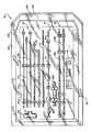
図1および2は、機能器具のシステム10を示す。使用中、システム10のある種の器具は、意図的な様式で展開されて、組織を貫通して、骨の内側への皮下アクセスを得る。骨の内側では、システム10の他の器具が展開されて、海綿質に空洞を形成し、この空洞の中には、処置目的のために、材料が配置される。Detailed Description of Preferred Embodiments
1 and 2 show a functional instrument system 10. In use, certain instruments of the system 10 are deployed in a deliberate manner to penetrate tissue and gain subcutaneous access to the inside of the bone. Inside the bone, other instruments of the system 10 are deployed to form a cavity in the cancellous material in which material is placed for treatment purposes.
図示した実施態様では、システム10は、3つの機能器具群14、16および18で、予め包装したキット12として、配列されている。第一群14(これは、図3にて、キット12の外側で示されている)は、その目的が骨内部への皮下アクセスを得ることにある器具を備える。第二群16(これは、図4にて、キット12の外側で示されている)は、その機能が海綿質で空洞を作成することにある器具を備える。第三群18(これは、図5にて、キット12の外側で示されている)は、その機能がこの空洞に材料を導入することにある器具を備える。In the illustrated embodiment, the system 10 is arranged as a
キット12は、種々の形状をとることができる。図示した実施態様では、キット12は、滅菌し包装したアセンブリを備える。 The
各機能器具群14、16および18およびキット12のそれ以上の詳細は、以下で述べる。 Further details of each
(I.皮下アクセス器具群)
群14の器具の数および種類は、変えることができる。図3は、5種の代表的な器具を示し、各々は、異なるサイズおよび機能を有する。(I. Subcutaneous access device group)
The number and type of instruments in
(A.脊髄針およびガイドピン)
図3で示すように、1つの器具は、従来の脊髄針アセンブリ20およびガイドピン器具26を備える。(A. Spinal needle and guide pin)
As shown in FIG. 3, one instrument includes a conventional
使用中、脊髄針アセンブリ20は、標的処置部位に至る初期皮下通路を確立する。ガイドピン器具26は、以下で記述するように、この通路を通って展開され、段々と大きくなる器具が続く。 In use, the
脊髄針アセンブリ20は、探査針22を備え、これは、スタイラス24内で、滑り可能に展開される。スタイラス24は、典型的には、例えば、約11ゲージの直径を有する。使用するガイドピン器具26のゲージに照らして、他のゲージの直径が使用できる。 The
使用中、ガイドピン器具26は、探査針22と交換して、脊髄針アセンブリ20で確立された皮下通路を通って、展開される。ガイドピン器具26は、標的処置部位への主要操作経路の確立を導くのに、役立つ。 In use, the
群14の残りの器具28、30および32は、いくつかの共通の特徴を共有するが、使用中は、異なる機能を実行することが意図される。これらの器具28、30および32は、それぞれ、剛性の外科等級プラスチックまたは金属材料から作製されている。これらの器具28、30および32は、それぞれ、近位末端34および遠位末端36を有する細長円筒形本体を備える。 The remaining
(B.栓塞器具)
器具28は、栓塞子として機能する。その遠位末端36は、貫通面38を呈するために、テーパが付けられている。使用中、表面38は、近位末端34で医師が加える押圧力または捻り力に応答して、軟組織を貫通することが意図される。(B. Plug device)
The
栓塞器具28の近位末端34は、フランジ面40を提供し、これは、近位末端34の方向で、大きい外径から小さい外径へとテーパになっている。フランジ面40は、周囲を取り巻いて間隔を開けた歯42のアレイを備える。 The proximal end 34 of the
内部管腔44は、遠位末端36から、栓塞器具28を通って、近位末端34へと伸長している。内部管腔44は、以下でさらに詳細に記述するように、ガイドピン器具26を収容するような大きさにされている。 The inner lumen 44 extends from the
(C.カニューレ器具)
器具30は、カニューレまたはガイド鞘として機能する。カニューレ器具30は、栓塞器具28よりも多少大きいが、栓塞器具28ほど長くない。カニューレ器具30は、その遠位末端36からその近位末端34へと伸長している内部管腔46を備える。内部管腔46は、栓塞器具28を受容する大きさにされている。内部管腔46のサイズにより、以下でさらに詳細に記述するように、医師は、栓塞器具28に対してカニューレ器具30を滑らせて回転したり、その逆を行うことが可能となる。(C. Cannula instrument)
The
カニューレ器具30の遠位末端36は、末端面48を呈する。使用中、カニューレ器具30の末端面48は、近位末端34で加えられる押圧力または捻り力に応答して、栓塞器具28を取り囲む軟組織を貫通することが意図される。 The
近位末端34は、拡大取付具50を備えている。取付具50は、近位末端34の方向で、大きい直径から小さい直径へとテーパになっている。栓塞器具28上のテーパ付きフランジ40と同様に、テーパ付き取付具50は、周囲を取り巻いて間隔を開けた歯52のアレイを備える。カニューレ器具30のテーパ付き取付具50は、栓塞器具28のテーパ付きフランジ40の最大外径よりも大きな最大外径を呈する。 Proximal end 34 includes an
カニューレ器具30は、その長さに沿って、測定刻印(measured markings)118を備える(図3を参照)。測定刻印118は、挿入深さを測る。刻印118は、例えば、1センチ間隔で配置できる。図3で示すように、刻印118は、医師が一瞥して挿入深さを確認できるように、遠位末端36から開始して、連続的に番号が付けられている。 The
(D.ドリルビット器具)
器具32は、ドリルビットとして機能する。ドリルビット器具32は、一般に、栓塞器具28と同じ物理的寸法を有する。栓塞器具28と同様に、ドリルビット器具32は、使用中、カニューレ器具30の内部管腔46内での滑り運動および回転運動に適することが意図される。(D. Drill bit instrument)
The
ドリルビット器具32の遠位末端36は、機械切削した切刃54を備える。使用中、切刃54は、ドリルビット32の近位末端34で加えられる回転力および長手軸方向負荷力に応答して、硬組織を貫通することが意図される。 The
近位末端34は、テーパ付きフランジ56を呈し、これは、栓塞器具28上のフランジ40と実質的に同じである。栓塞器具28と同様に、テーパ付きフランジ56は、近位末端34の方向で、大きい直径から小さい直径へと変わる。ドリルビット器具32のテーパ付きフランジ56はまた、周囲を取り巻いて間隔を開けた歯58のアレイを備える。ドリルビット器具32上の歯58の形状および配向は、栓塞器具28上の歯42の形状および配向と対応している。 The proximal end 34 exhibits a tapered
(E.ハンドル)
この群は、ハンドル60を備える。ハンドル60は、医師が使用中に機能器具28、30および32を操作するのを助けるために、取り外し可能な滑り嵌合様式で、これらの機能器具と係合する。(E. Handle)
This group includes a
ハンドル60は、成形または鋳造した剛性プラスチックまたは金属材料から製造される。ハンドル60は、普通のヒトの手で快適かつ確実に握れるような形状にされる。この機能に適応する形状およびサイズは、もちろん、変えることができる。図示した実施態様では、ハンドル60は、このハンドルの掌部と快適に適合するように、主軸に沿って延びている。 The
ハンドル60は、中心ポート62を備え、これは、ハンドル60の幾何学中心の付近で、そこに一体的に成形されている。中心ポート62は、ハンドル60に略T形状を与えるように、下方に伸長している。 The
ハンドル60は、中心ポート62にて、2個の内部空洞またはソケット64および66を備える。これらのソケットは、ハンドル60と器具28、30および32との間の装着を案内する。第一および第二ソケット64および66は、異なる機能器具に対して特有の装着部位を与えるような大きさにされている。
第一ソケット64は、周囲を取り巻いて間隔を開けた溝部68のアレイを備え、これは、形状および配向の点で、栓塞器具28およびドリルビット器具32の近位末端34にある歯42および58に合う。第一ソケット64は、栓塞器具28またはドリルビット器具32のいずれかのテーパ付きフランジ40または56を受容する。テーパ付きフランジ40または56のいずれかの歯42および58は、第一ソケット64の溝部68と滑り嵌合で係合する。滑り嵌合が延びていることにより、ハンドル60を介して、器具28または32のいずれかに、長手軸方向力を加えることが可能となる。この滑り嵌合が延びていることにより、また、器具28または32のいずれかと第一ソケット64との間の相対的な回転が防止され、それにより、ハンドル60によって、器具28または32のいずれかに、捻り力または捩り力を加えることが可能となり、機械的な利点が増す。 The
第二ソケット66は、第一ソケット64よりも大きく、カニューレ器具30の大きい方のテーパ付き取付具50を受容する大きさにされている。第二ソケット66は、周囲を取り巻いて間隔を開けた溝部70のアレイを備え、これは、形状および配向の点で、テーパ付き取付具50上の歯に合う。テーパ付き取付具50の歯52は、第二ソケット66の溝部70と滑り嵌合で係合する。この滑り嵌合が延びていることにより、ハンドル60を介して、カニューレ器具30に、長手軸方向力および捻り力の両方を加えることが可能となる。 The
図3にて点線で示すように、ハンドル60の頂部を通り、中心ポスト62を通り、第一ソケット64に入って、第一通路72が伸長している。通路72は、大体、第一ソケット64の中心と整列しており、ガイドピン器具26を通る大きさにされている(図12を参照)。 As shown by the dotted line in FIG. 3, the
同様に、また、図3にて点線で示すように、ハンドル60の頂部を通り、中心ポスト62を通り、第二ソケット66に入って、第二通路74が伸長している。通路74は、大体、第二ソケット66の中心と整列しており、栓塞器具28またはドリルビット器具32のいずれかを通る大きさにされている(図14を参照)。 Similarly, as indicated by the dotted line in FIG. 3, the
ハンドル60さらなる詳細は、継続中の米国特許出願第09/014,229号(これは、1998年1月27日に出願され、そして「A Slip−Fit Handle for Hand−Held Instruments that Access Interior Body Regions」の表題である)にある。 For further details on
ハンドル60およびそれに付随した器具26、28および30の使用に関するさらなる詳細は、以下で述べる。 Further details regarding the use of the
(II.空洞形成器具)
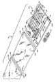
図4Aで示すように、群16は、器具76を備え、これは、カニューレ器具30を通って、骨の内側の位置まで展開されている(図20を参照)。そのように展開したとき、器具76は、海綿質にて空洞を形成するのに役立つ。(II. Cavity forming device)
As shown in FIG. 4A, the
器具76は、種々の様式で作成できる。図示した実施態様では、器具76は、近位末端80および遠位末端82を有する可撓性カテーテルチューブ78を備える。近位末端80は、カテーテルチューブ78を握って操作するのを容易にするために、ハンドルグリップ84を備えている。カテーテルチューブ78用の材料は、カニューレ器具30を通るその前進を容易にするように、選択される。カテーテルチューブ78は、例えば、ビニール、ナイロン、ポリエチレン、アイオノマー、ポリウレタンおよびポリエチレンテレフタレート(PET)のような標準的な可撓性の医用等級プラスチック材料を使用して、作成できる。カテーテルチューブ78はまた、高い剛直性を与えてその操作を助けるために、さらに剛性の材料を含むことができる。この目的に使用できるさらに剛性の材料には、ステンレス鋼、ニッケル−チタン合金(Nitinol(登録商標)材料)、および他の金属合金が挙げられる。 The
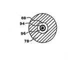
器具76の遠位末端82は、拡大可能構造体86を備えている。図示した実施では、拡大可能構造体86は、ポリウレタンまたはエラストマー(例えば、シリコーンまたはナイロン)材料から製造されている。構造体86は、例えば、従来の熱成形技術を使用することによって、熱および圧力に曝すことにより、所望の形状を有するように前成形されている。 The distal end 82 of the
図4Bで示すように、カテーテル本体78は、内部管腔88を含み、これは、構造体86の内部と連絡している。カテーテルチューブ78(図4Bを参照)の近位末端80上の取付具90は、管腔88と連絡している。取付具90は、管腔88を、流体(例えば、滅菌生理食塩水(例えば、図21を参照)または放射線不透過性造影剤)源92に連結する。 As shown in FIG. 4B, the
この流体は、正圧下にて、源92から構造体86へと導入されて、構造体86を拡大させる。骨の内側で拡大している間、構造体86に対して選択された材料は、好ましくは、変形に抵抗して、その結果、骨の内側で拡大した形状は、事実上、骨の外側でのその拡大形状(すなわち、外気環境にあるとき)に対応する。これにより、医師は、外気環境にて、骨の内側で拡大した形状が重要な点で類似しているとの自信を持って、目標とする処置結果を満たすのに望ましい拡大形状を有する構造体86を選択することが可能となる。骨の内側での変形に抵抗しつつ、その容量を拡大できることに加えて、好ましい構造体86の材料は、海綿質と接触したとき、摩滅、引き裂きおよび穿刺に耐える。 This fluid is introduced from the
骨の内側で拡大したときの構造体86の形状は、処置する部位の形態および外形を考慮して、医師により選択される。圧迫する海綿質の形状、および骨が不適当に移動したときに傷つき得る局部構造体は、一般に、この部位およびその疾患または傷害の知識と共に、ヒトの骨格構造の教本を使用して、医学の専門家により理解されている。医師はまた、例えば、プレインフィルム(plain film)X線、蛍光透視X線、またはMRIまたはCT走査を使用して、標的骨の形態を予め分析することに基づいて、骨の内側の拡大形状を選択できる。骨の内部の拡大形状は、例えば、適当な材料で充填したとき、処置する骨の領域にわたって支持を与える空洞の形状を最適化するように、選択される。 The shape of the
1つの一般的なガイドワイヤとして、骨折を引き起こす(または骨折の危険がある)骨の疾患が海綿質塊の損失にある場合(骨粗しょう症の場合など)、骨の内側にある構造体86の拡大形状の選択は、海綿質の容量の30%〜90%が緻密化すべきであることを考慮しなければならない。他の一般的な指針には、骨折した標的骨領域が交換または押し下がる量がある。骨の内側での海綿質領域内にある構造体86の拡大は、骨折が起こる前にそれが占めていた身体位置またはその近くに、骨折した皮質壁を高めるか押し戻すことができる。 As one common guidewire, if the bone disease that causes the fracture (or is at risk of fracture) is a loss of cancellous mass (such as in osteoporosis), the
図示した実施態様(図4Aを参照)では、構造体86は、前成形した砂時計形状またはピーナッツ形状を有する。この形状は、以下でさらに詳細に記述するように、椎体で構造体86を展開することを予期して、選択される。 In the illustrated embodiment (see FIG. 4A), the
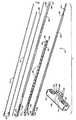
カニューレ器具30を通って構造体86を展開し易くするために、カテーテルチューブ78は、第二内部管腔94を含む。管腔94は、カテーテルチューブ78の近位末端80上の第二取付具98から、カニューレチューブ78の本体を通り、構造体86の内部を通って、構造体86の先端172まで延びる。管腔94は、ほぼ剛性の探査針96(これは、成形したプラスチックまたはステンレス鋼材料から製造できる)を受容する。探査針96は、取付具98を通って、管腔94に挿入され、探査針96が移動しないように固定するためのネジ付き連結部100を含む。探査針96の存在は、構造体86がカニューレ器具30を通過して標的組織領域に入る間、構造体86を、所望の遠位で真っ直ぐになった状態にするのに役立つ。一旦、構造体86がカニューレ器具30から離れて骨の内側に入ると、探査針96は、(図4Aにて矢印174で示すように)、引き出すことができる。これにより、カテーテルチューブ78が通常の可撓性を取り戻し、骨の内側で構造体86を操作し易くする。探査針96を引き出すと、管腔94はまた、リンス液を導入したり骨から細片を吸引するための経路として、役立つことができる。 To facilitate deployment of the
図示した実施態様では、探査針96は、略直線状態へ付勢されている。代替実施態様(図4Cを参照)では、探査針102は、その遠位領域を正しく曲げるために、前成形メモリーを有し得る。このメモリーは、カニューレ器具30内に閉じこめられているとき、探査針102を真っ直ぐになることに打ち勝つ。しかしながら、構造体86と前成形探査針102の遠位領域とがカニューレ器具30から離れて前進して標的領域に入るにつれて、前成形メモリーは、探査針102の遠位領域を曲げ、それにより、拡大可能構造体86の主軸をずらす。予め曲げた探査針102は、構造体86の内部に位置しているが、構造体86の配向を変えるのを助け、それを、標的領域とうまく解剖的に整列させるようにする。 In the illustrated embodiment, the
海綿質および他の内部身体領域で空洞を形成できる他の型の器具は、係属中の米国特許出願第09/055,805号(これは、「Structures and Methods for Creating Cavities in Interior Body Regions」の表題であり、1998年4月6日に出願された)で記述されている。 Other types of devices that can form cavities in cancellous and other internal body regions are described in pending US patent application Ser. No. 09 / 055,805 (this is “Structures and Methods for Creating Cabinages in Interior Body Regions”). Title, filed on Apr. 6, 1998).
(III.材料導入器具群)
群18は、器具104、106および108を含み、これらは、構造体86により形成された空洞の内側で、選択した材料を運び緻密化するのに役立つ。この材料は、この空洞内で、所望の処置結果、例えば、組織塊の交換、または骨に対する新たな内部支持、または薬物の送達、またはそれらの組合せを与える。従って、この機能を実行するための材料は、例えば、硬化状態に固化する材料(骨セメント、自家移植組織、異系移植組織、合成骨代替物だけでなく、薬物、またはそれらの組合せを含めて)のうちから選択できる。(III. Material introduction equipment group)
図示した実施態様では、群18は、材料注入器具104および106、および材料タンピング器具108を含み、これらは、低い送達圧力(例えば、約360psi以下の圧力)で、材料を送達する。 In the illustrated embodiment,
(A.低圧材料注入器具)
図示した実施態様では、この材料は、通常の注射器104を使用することにより注入され、それには、特別に設計した注射器ノズル106が連結されている。プッシュプランジャーを備えた手動注射器が使用できる。あるいは、ネジ付きプランジャーを備えたLeVeen Inflation Syringeが使用でき、これは、手で、または機械的なアクチュエータを使用して、作動できる。(A. Low-pressure material injection device)
In the illustrated embodiment, this material is injected by using a
図示した実施態様では、注射器104は、透明なプラスチック材料から製造されている。注射器104は、チャンバ110を含み、これは、注入する材料を受容する。この材料は、手で前進させた注射器ピストンにより、チャンバ100から発せられる(また、図25を参照)。 In the illustrated embodiment, the
注入ノズル106は、ネジ付きコネクタ114により、注射器104の末端に接続する(また、図25を参照)。図示した実施態様では、ノズル106は、ほぼ可撓性の不活性プラスチック材料(例えば、ポリエチレンまたは他の適当なポリマー)から製造されている。あるいは、ノズル106は、ほぼ剛性のプラスチックまたは金属材料から製造できる。 The
注入ノズル106は、カニューレ器具30を通って前進するような大きさにされている(図26を参照)。ノズル106は、その長さに沿って、測定刻印116を含む。刻印116は、カニューレ器具30上の刻印118と対応するように、例えば、1センチ間隔で配置でき、その結果、カニューレ器具30内でのノズル116の相対位置を測ることができる。刻印118は、例えば、設定点176を含むことができる。カニューレ器具30の遠位末端34で設定点176が整列していることは、ノズル106の遠位末端は、カニューレ器具30の遠位末端36と整列した関係で位置していることを示している。この配列では、刻印118は、連続的に、設定点176から近位の方へは正の番号が付けられ、また、設定点176から遠位の方へは負の番号が付けられている。医師は、それにより、ノズル106の遠位末端の位置を一瞥して、カニューレ器具30の遠位末端36からどの程度越えているかまたは足りないかについて、知ることができるようになる。
使用中、ノズル106の遠位末端は、標的組織領域で形成された空洞内にて、カニューレ器具30の遠位末端36を越えて位置している。図5で示すように、ノズル106の遠位末端は、プラスチック材料から製造されるとき、このノズルの体内での位置を遠隔で視覚化できるように、少なくとも1個の放射線不透過性マーカー208を備えることができる。注射器104は、所定用量の材料をノズル106へと排出し、低圧流れで、この空洞に入れる。この材料がこの空洞を満たすにつれて、このノズル(これは、依然として、材料を排出している)は、この空洞から、カニューレ器具30それ自体へと後退される。この機能および結果のそれ以上の詳細は、以下で述べる。 In use, the distal end of the
(B.材料タンピング器具)
群18はまた、材料タンピング器具108を含む。タンピング器具108は、ほぼ剛性で不活性のプラスチックまたは金属材料から製造されている。タンピング器具108はまた、カニューレ器具30へと前進するような大きさにされている(図30を参照)。タンピング器具108の自由端124は、使用中に器具108を握り易くするために、リブ付けされ、または等高線状にされている。(B. Material tamping equipment)
タンピング器具108は、その長さに沿って、測定刻印122を含む。刻印116は、カニューレ器具30上の刻印118と対応するように、例えば、1センチ間隔で配置でき、その結果、カニューレ器具30内でのタンピング器具108の相対位置を測ることができる。ノズル106と同様に、タンピング器具108上の刻印122は、設定点178を含むことができ、これは、タンピング器具108の遠位末端がカニューレ器具30の遠位末端36と整列しているときを示す。また、ノズル106と同様に、タンピング器具108上の刻印122は、連続的に、設定点178から近位の方へは正の番号が付けられ、また、設定点178から遠位の方へは負の番号が付けられている。医師は、それにより、タンピング器具108の遠位末端の位置を一瞥して、カニューレ器具30の遠位末端36からどの程度越えているかまたは足りないかについて、知ることができるようになる。図5はまた、タンピング器具108(これがプラスチック材料から製造されるとき)の末端を示し、これは、少なくとも1個の放射線不透過性マーカー210を備えることができ、その結果、その位置は、身体の外側から視覚化できる。 The tamping
ノズル106をカニューレ器具30から引き出した後、カニューレ器具30には、残留材料が残る。タンピング器具108の目的は、この残留材料をカニューレ器具30の遠位末端からこの空洞へと移動し、それにより、骨内に過度の圧力を加えることなく、この空洞を満たすことにある。タンピング器具108は、それにより、カニューレ器具30から残留材料を取り除いて、所望容量の材料がこの空洞に送達されるのを保証するの役立つ。タンピング器具108によってカニューレ器具30から残留材料を除去することにより、また、カニューレ器具30を取り除いた際の周囲の組織領域への材料の滲出が防止される。タンピング器具108はまた、再度、過度の圧力なしで、この空洞内にて、この材料を均一に緻密化する。これらの機能および結果のそれ以上の詳細は、以下で述べる。 After the
(IV.キット)
図1および2で示すように、図示した実施態様では、キット12は、内部トレイ126(これは、例えば、打ち抜きダンボール、プラスチックシートまたは熱形成プラスチック材料から製造される)を含む。トレイ126は、間隔を置いて配置しタブ128を含み、これは、使用前の滅菌および保存中にて、種々の器具を確実な位置で保持する。(IV. Kit)
As shown in FIGS. 1 and 2, in the illustrated embodiment, the
キット12は、無菌アセンブリとして包装するとき、内部包装130を含み、これは、熱などによって周辺で密封されて、トレイ126を外部環境との接触から囲う。この内部包装の一端は、使用の瞬間にトレイ126への迅速なアクセスを与えるために、通常の剥ぎ取りシール132を含み、これは、好ましくは、無菌環境(例えば、手術室内)で生じる。 When packaged as a sterile assembly, the
キット12はまた、無菌アセンブリとして包装するとき、外部包装134を含み、これもまた、熱などによって周辺で密封されて、内部包装130を包む。この外部包装の一端は、内部包装130およびその内容物へのアクセスを与えるために、通常の剥ぎ取りシール136を含む。外部包装134は、差し迫った使用を見越して、キット12の内容物の無菌性を損なうことなく、この内部包装から取り除くことができる。 The
図2で示すように、各内部および外部包装130および134は、周辺で密封された上部シート138および下部シート140を含む。図示した実施態様では、上部シート138は、キット12の内容物を視覚的に確認できるように、ポリエチレンまたはMYLAR(登録商標)材料のような透明プラスチックフィルムから製造されている。下部シート140は、ETO滅菌ガス、例えば、TYVEK(登録商標)プラスチック材料(これは、DuPontから入手できる)を透過できる材料から製造されている。 As shown in FIG. 2, each inner and
図示した実施態様では、トレイ126では、順序だてて整理したレイアウトで、器具14、16および18が見え、これは、医師が目的の処置を行うのを助けるように配列されている。例えば、トレイ126のレイアウトでは、目的用途の手順に従って、上から下への順序で、器具14、16および18を置くことができる。例えば、典型的な骨アクセス処置(これは、以下でさらに詳細に示す)では、脊髄針アセンブリ20の探査針22およびスタイラス24が、まず、展開され、続いて、ガイドピン器具26が展開され、続いて、栓塞器具28が展開され、次いで、カニューレ器具30が展開され、次いで、ドリルビット器具32が展開され、次いで空洞形成器具76が展開され、次いで、注射器104およびノズル106器具が展開され、最後に、タンピング器具108が展開される。従って、トレイ126は、これらの器具および部品を上から下へと包装し、脊髄針アセンブリ20は、最上部にあり、ガイドピン器具26は、次にあり、栓塞器具28は、その次にあるなどして、タンピング器具108は、トレイ126の最下部になる。 In the illustrated embodiment, tray 126 shows
このレイアウトでは、ハンドル60は、アクセス器具群14の側面に包装されている。トレイ126は、キット12に含まれている部品を識別する書き込みラベル(図示せず)を含むことができる。 In this layout, the
キット12はまた、好ましくは、所望の処置を実行するために、トレイ126中に、キット12の内容物を使用するための手引き144を含む。手引き144が説明できる代表的な手順を、以下で説明する。 The
手引き144は、無菌アセンブリとして包装するとき、また、その性能特性および効能が1回使用した後に低下するキット12の内容物を再使用することに断固として反対して注意する「For Single Patient Use Only」(または同様の言葉)の記載を含むことができる。脊髄針アセンブリ20、空洞形成器具76、および材料導入器具104、106および108は、これらの理由のために、1回だけ使用して捨てるべきである。手引き144はまた、好ましくは、キット12の少なくともこれらの内容物を再滅菌することに積極的に反対するように指示し、また、外科医に対して、適用可能な生体廃棄物処置に従って、使用するとキット12の少なくともこれらの内容物を廃棄するように指示する。 The
器具群14、16および18が無菌キット12に包装されていることで、医師は、これらの内容物が無菌であり以前に使用されなかったことを確認する。医師は、それにより、これらの器具群が特定の性能および無菌性の仕様を満たすと確信する。 With the
キット12に含まれる種々の説明書は、いくつかの小さな機能キットに包装できることを理解すべきである。例えば、第一キットは、アクセス器具群14を包装でき、第二キットは、空洞形成器具群16を包装でき、そして第三キットは、材料導入器具群18を包装できる。図1および2は、多くの異なる可能な実施態様の1つを図示している。 It should be understood that the various instructions included in
(V.システムの例証的な用途)
以下では、骨を処置することに関連して、キット12に包装された器具群14、16および18の用途を記述する。これは、群14、16および18の器具がこの目的のために有利に使用できるからである。これらの器具群の1個またはそれ以上(これらは、単独で、または他の器具と共同で、使用される)は、身体の他の内部領域において、他の診断機能または処置機能を実行できることを理解すべきである。(V. Illustrative use of the system)
In the following, the use of the
特に、器具群14、16および18は、ヒトの椎骨の処置に関して、記述されている。しかしながら、それらの用途は、ヒトの椎骨には限定されないことを理解すべきである。器具群14、16および18は、ヒトまたは動物の多様な種類の骨を処置する際に、携帯型の器具と共同で、使用できる。 In particular,
(A.椎体)
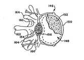
図6および7は、典型的な椎骨146が椎体148を含み、これが、椎骨146の前方(すなわち、前部または胸部)側で延びることを示している。椎体148は、卵形の円板形状を有する。椎体148は、緻密な皮質骨150から形成された外部を含む。皮質骨150は、網状の海綿状またはスポンジ状骨152(これはまた、延髄骨または小柱骨とも呼ばれる)の内部容量を囲む。(A. Vertebral body)
FIGS. 6 and 7 show that a
脊髄154は、椎骨146の脊柱管156を通る。椎弓158は、脊柱管156を取り囲んでいる。椎弓158の椎弓根160は、椎体148に隣接している。棘突起162は、左または右横突起164と同様に、椎弓158の後方から延びる。 The
(B.椎体の処置)
典型的な処置では、患者は、手術台に横臥する。患者は、医師の選好に依存して、手術台にうつぶせになるか、横向けになるか、または傾斜角にできる。(B. Treatment of vertebral body)
In a typical procedure, the patient lies on the operating table. The patient can lie on the operating table, lay sideways, or tilted, depending on the physician's preference.
医師または外科補助員は、キット12の外部および内部包装130および134を取り除いて、使用のためにトレイ126を露出させる。医師は、トレイ126から、脊髄針アセンブリ20を得る。図8で示すように、医師は、脊髄針アセンブリ20を、患者の背中にある軟組織STに導入する。放射線またはCTモニタリング下にて、医師は、脊髄針アセンブリ20を、軟組織を通って下に前進させ、標的椎骨146に入れる。医師は、典型的には、アセンブリ20に局所麻酔(例えば、リドカイン)を行なう。ある場合には、医師は、他の麻酔方法を好み得る。 A physician or surgical assistant removes the outer and
医師は、脊髄針アセンブリ20が標的椎体148の皮質骨150および海綿質152を貫通するように向ける。好ましくは、貫通深さは、椎体148の約60%〜95%である。 The physician directs
図8は、椎体148の側面を通る海綿質へのアクセスを得ることを示し、これは、後外側アクセスと呼ばれる。しかしながら、アクセスは、椎弓根160を通って指示され得、これは、椎弓根横断アクセスと呼ばれる。このアクセス型は、この処置目的に基づいているか、または他の理由のために、医師の選好に基づいている。 FIG. 8 shows gaining cancellous access through the sides of the
図9で示すように、脊髄針アセンブリ20を海綿質152に位置づけた後、医師は、スタイラス24を保持し、そして探査針22を引き出す。医師は、トレイ126からガイドピン器具26を得る。図10で示すように、依然として、スタイラス24を保持しつつ、医師は、スタイラス24を通って海綿質152へと、ガイドピン器具26を滑らせる。医師は、今ここで、スタイラス24を取り除き(図11を参照)、ガイドピン器具26を、海綿質152内に展開したままにする。 As shown in FIG. 9, after positioning the
医師は、次に、トレイ126から、栓塞器具28およびハンドル60を得る。医師は、遠位末端を最初にして、栓塞器具28をガイドピン器具26上に滑らせる。医師は、ハンドル60の第一通路72および第一ソケット64を通って、ガイドピン器具26を滑らせる。図12で示すように、医師は、先に記述した様式で、第一ソケット64とテーパ付きフランジ40との間で延びている滑り嵌合が達成されるまで、ガイドピン器具26に沿って、栓塞器具28のテーパ付きフランジ40の方へと、ハンドル60を滑らせる。栓塞器具28は、今ここで、使用できる状態である。 The physician then obtains the
図12で示すように、医師は、患者の背中に、小さな切開部Iを作製する。医師は、ハンドル60に長手方向力を加えつつ、ハンドル60を捻る。それに応えて、栓塞器具28の表面が回転し、切開部Iを通って、軟組織STを貫通する。医師はまた、ハンドル60を軽く叩くか、そうでなければ、ハンドル60に適当な追加長手方向力を加えて、この軟組織を通って、ガイドピン器具26に沿って、その入口部位に至るまで、栓塞器具28を前進させる(図13を参照)。医師はまた、適当な打撃器具を使ってハンドル60を叩いて、栓塞器具28の表面30を椎体148の側面へと前進させて、その位置を(図13で示すように)固定できる。 As shown in FIG. 12, the doctor makes a small incision I on the patient's back. The doctor twists the
医師は、次に、栓塞器具28から離れて、ガイドピン器具26に沿って、ハンドル60を滑らせて、テーパ付きフランジ40を第一ソケット64から外す。医師は、次いで、ガイドピン器具26から完全に外れるように、ハンドル60を滑らし続ける。 The physician then slides the
医師は、トレイ126からカニューレ器具30を得る。図14で示すように、医師は、末端面48と軟組織STとの間で接触するまで、遠位末端を最初にして、カニューレ器具30をガイドピン器具26上に滑らせ、さらに、栓塞器具28上に滑らせる。医師は、今ここで、ハンドル60の第二通路74および第二ソケット66を通って、ガイドピン器具26および栓塞器28を滑らせる。医師は、先に記述した様式で、第二ソケット66とテーパ付きフランジ50との間で延びている滑り嵌合が達成されるまで、カニューレ器具30のテーパ付き取付具50の方へと、ハンドル60を滑らせる。カニューレ器具30は、今ここで、使用できる状態である。 The physician obtains
図14で示すように、医師は、ハンドル60に適当な捻れ力および長手方向力を加えて、栓塞器具28に沿って、軟組織STを通って、カニューレ器具30を回転し前進させる。図15で示すように、カニューレ器具30の末端面48が皮質骨と接触するとき、医師は、打撃器具を使って、ハンドル60を適当に叩いて、この末端面を椎体148の側面へと前進させて、その位置を固定できる。 As shown in FIG. 14, the physician applies appropriate torsional and longitudinal forces to the
図16で示すように、医師は、今ここで、栓塞器具28を引き出し、それをガイドピン器具26から離れて滑らせる。これにより、ガイドピン器具26およびカニューレ器具30は、図17で示すように、適当な位置で残る。医師は、次に、ガイドピン器具26に沿って、カニューレ器具30から離れて、ハンドル60を滑らせて、テーパ付き取付具50を第二ソケット66から外す。医師は、次いで、ガイドピン器具26から完全に外れるように、ハンドル60を滑らせる。 As shown in FIG. 16, the physician now pulls the
医師は、今ここで、トレイ126からドリルビット器具32を得る。図18で示すように、医師は、機械切削面54と骨組織との間で接触が起こるまで、遠位末端を最初にして、ドリルビット器具32をガイドピン器具26上に滑らせ、さらに、カニューレ器具30に通す。図18でまた示すように、医師は、次に、ハンドル60の第一通路72およ第一ソケット64を通って、ガイドピン器具26を導く。医師は、先に記述した様式で、第一ソケット64とテーパ付きフランジ56との間で延びている滑り嵌合が起こるまで、ガイドピン器具26に沿って、ドリルビット器具32のテーパ付きフランジ56の方へと、ハンドル60を滑らせる。ドリルビット器具32は、今ここで、使用できる状態である。 The physician now obtains the
図18で示すように、X線(または他の外部視覚化システム)で案内されて、医師は、ハンドル60に適当な捻れ力および長手方向力を加えて、ドリルビット器具32の切刃54を回転し前進させて、骨組織を通って海綿質152へと完全に入る通路166を開く(図19を参照)。穿孔した通路166は、好ましくは、椎体148を横切って、95%以下で延びる。 As shown in FIG. 18, guided by X-rays (or other external visualization system), the physician applies appropriate torsional and longitudinal forces to the
医師は、今ここで、ガイドピン器具26に沿って、ドリルビット器具32から離れて、ハンドル60を滑らせて、テーパ付きフランジ56を第一ソケット64から外す。医師は、さらに、ガイドピン器具26から完全に離れて、ハンドル60を滑らせる。 The physician now slides the
医師は、今ここで、ドリルビット器具32およびガイドピン器具26を取り外し、カニューレ器具30だけを適当な位置に残すことができる。ドリルビット器具32で作製された通路166が残る。海綿質152への皮下アクセスが達成される。 The physician can now remove the
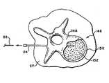
医師は、今ここで、トレイ126から空洞形成器具を得ることができる。図20で示すように、医師は、カニューレ器具30および通路166を通って、椎体148の内部容量へと、拡大可能構造体86を前進できる(これはまた、図21でも示している)。構造体86は、展開中に、それが通常崩壊するが拡大しない状態にある。探査針96または102は、カテーテルチューブ78の管腔94に挿入されて、カニューレ器具30を通りつつ、構造体86に剛直性を追加する。 The physician can now obtain the cavity forming device from the tray 126. As shown in FIG. 20, the physician can advance
図20にて点線で示すように、医師は、もし望ましいなら、ハンドル60をカニューレ器具30に再接続して、構造体86を展開しつつ、カニューレ器具30を安定化するのを助ける。このハンドルの第二通路74は、崩壊したとき、カテーテルチューブ78および構造体86を収容する。 As indicated by the dotted lines in FIG. 20, the physician reconnects the
図21で示すように、構造体86は、通路166にて、所望の様式で配向されている。前に説明したように、曲げた探査針102は、この作業を助けることができる。この配向過程の前、最中または後に、探査針96または102は、(図21で示すように)引き出して、リンス液または負吸引圧を通すのに使用するために、管腔94を開けることができる。 As shown in FIG. 21, the
圧力下にて、源92から、管腔88を通って、構造体86へと、無菌液が運ばれる。図22で示すように、構造体86は、骨の内側で拡大する。構造体86の拡大により、椎体148にある海綿質152が圧迫される。 Under pressure, sterile fluid is carried from the
この圧迫により、海綿質152において、内部空洞168が形成される。図23で示すように、構造体86を引き続いて崩壊し取り出すことにより、空洞168は、充填材料を受容する状態で残る。 By this compression, an
海綿質152の緻密化もまた、皮質骨に内圧を加えることができ、崩壊して圧迫された骨を、その初期の骨折前状態または他の望ましい状態またはそれに近い状態に上昇させるかまたは押し戻すことが可能となる。 The densification of
空洞168が形成されると、医師は、キット12から注射器104および注入ノズル106を得る。図24で示すように、医師は、注射器チャンバ110を、所望容量の充填剤170で満たす。図25で示すように、医師は、充填した注射器104にノズル106を取り付ける。図26で示すように、医師は、刻印116で案内して、カニューレ器具30の遠位末端36を越えて選択した距離で、この空洞へとノズル106を挿入する。 Once the
図26にて点線で示すように、ハンドル60は、このハンドルの第二通路74がノズル106を収容するにつれて、安定性を与えるために、カニューレ器具30に装着したままにできる。 As shown by the dotted lines in FIG. 26, the
図27で示すように、医師は、ピストン112を手で前進させて、材料170をノズル106からそこを通ってこの空洞へと流す。材料170がこの空洞を満たすにつれて、医師は、この空洞からカニューレ器具30へと、このノズルを引き出す。カニューレ器具30は、材料170の流れを空洞168の方へと向ける。図28で示すように、セメント材料170は、空洞168へと続々と流れる。 As shown in FIG. 27, the physician manually advances
もし、選択した材料170が骨セメントなら、セメント材料170は、薄いホットケーキのバターのように低い粘度で比較的に自由に流れる液体状態であって、2種の材料を(例えば、外部混合装置で)混合した直後に、注射器チャンバ110に配置される。時が経てば(例えば、混合後、約2分間)、セメント材料170の粘稠度は、実質的にパテ様の特性に変わる。 If the selected
医師は、注射器104を操作して、セメント材料170を、このチャンバから吐き出し、ノズル106を通って、まず、この空洞に入れ、次いで、カニューレ器具30に入れる。典型的には、この注射器注入過程の最後に、材料170は、この空洞から延びて、カニューレ器具30の約40%〜50%を占めるべきである。 The physician operates the
注射器104から所望容量のセメントが吐き出されると、医師は、図29で示すように、カニューレ器具30からノズル106を引き出す。医師は、まず、注射器104およびノズル106を回転して、カニューレ器具30を占める排出薬物適用1回分の材料170から、ノズル106内の材料170を離し得る。 When the desired volume of cement is expelled from the
医師は、キット12からタンピング器具108を得る。図30で示すように、医師は、カニューレ器具30を通って、タンピング器具108を前進させる。 図30にて点線で示すように、ハンドル60は、このハンドルの第二通路74がタンピング器具108を収容するにつれて、安定性を与えるために、カニューレ器具30に装着したままにできる。 The physician obtains the
タンピング器具108の遠位末端は、カニューレ器具30内の残留容量のセメント材料170と接触する。図30および31で示すように、タンピング器具108を前進させることにより、カニューレ器具30に由来の残留材料170が段々と多く移動して、それを空洞168に強制的に入れる。空洞168への材料170の流れは、カニューレ器具30内でのタンピング器具108の前進により推進されるが、過度の圧力を加えることなしに、材料170を空洞168の内側に均一に分配して緻密化するのに役立つ。 The distal end of the tamping
注射器104、ノズル106およびタンピング器具108を使用すると、医師は、この空洞を材料170で満たしたとき、正確に制御できるようになる。医師は、遭遇する特定の局所的な生理学的状態に従って、送達容量および送達速度を直ちに調節できる。低い圧力(すなわち、360psi以下)(これは、注射器104およびタンピング器具108により、均一に加えられる)を加えると、医師は、事実上、瞬間的な様式で、充填容量および流れ抵抗の条件に応答できるようになる。材料170を充填し過ぎてこの空洞の外側に漏れる危険は、著しく少なくなる。 Using the
材料170が空洞168の内側に充分に分配されたと医師が納得したとき、医師は、カニューレ器具30からタンピング器具108を引き出す。医師は、好ましくは、まず、タンピング器具108を捻って、材料170との接触をきれいに切断する。図32で示すように、ハンドル60は、今ここで、取り除くことができ、カニューレ器具30を引き出すことができる。この切開部位は、縫合して閉じられる。この骨治療処置は、完結する。 When the physician is satisfied that the
最終的に、材料170は、もしセメントなら、空洞168内で剛性状態に硬化する。椎体148が負荷に耐える性能は、それにより、改良される。 Eventually,
選択した材料170は、通常の様式で収集された自家または異系骨移植片であり得る。例えば、この移植片材料は、Dickにより、「Use of the
Acetabular Reamer to Harvest Autogenic Bone Graft Material;A Simple Method for Producing Bone Paste」、Archives of Orthopaedic and Traumatic Surgery(1986),105:235〜238で記述されているように、ペースト形状で、またはBhanにより、「Percutaneous Bone Grafting for Nonunion and Delayed Union of Fractures of the Tibial Shaft」、International Orthopaedics(SICOT)(1993)17:310〜312で記述されているように、ペレット形状であり得る(両方の文献の内容は、本明細書中で参考として援用されている)。あるいは、この骨移植片組織は、Bone Graft Harvester(これは、SpineTechから入手できる)を使用して、得ることができる。漏斗を使用して、このペーストまたはペレット移植片材料は、カニューレ器具30に装填される。次いで、先に記述した様式で、カニューレ器具30には、タンピング器具108が前進されて、このペーストまたはペレット移植片組織材料を、カニューレ器具30からこの空洞へと移動する。The selected
“A Simple Method for Producing Bone Paste”; Percutaneous Bone Grafting for Nonunion and Delayed Union of Fractures of the Tibular Shaft, described in International Orthopedics (SICOT) (1993) 17: 310-312. Obtained (at the contents of both documents are incorporated herein by reference). Alternatively, the bone graft tissue can be obtained using a Bone Graft Harvester (which is available from SpineTech). Using a funnel, this paste or pellet graft material is loaded into the
選択した材料170はまた、サンゴから収穫した顆粒骨材料(例えば、Interporeから入手できるProOsteon(登録商標)炭酸カルシウム顆粒)を含有できる。これらの顆粒は、漏斗を使用して、カニューレ器具30に装填され、そしてタンピング器具108を使用して、この空洞に前進される。
選択した材料170はまた、グリセロールに懸濁した脱塩骨マトリックス(例えば、Osteotechから入手できるGrafton(登録商標)異系移植片材料またはNovianから入手できるSRS(登録商標)リン酸カルシウムセメント)を含有できる。これらの粘稠な材料は、先に記述した骨セメントと同様に、注射器104に装填でき、そしてノズル106(これは、カニューレ器具30を通って、この空洞に挿入される)を使用して、この空洞に注入できる。タンピング器具108は、前に記述したように、残留材料をカニューレ器具30からこの空洞へと移動するのに使用される。
選択した材料170はまた、シート形状(例えば、炭酸カルシウム粉末およびウシ骨由来コラーゲンから製造されるCollagraft(登録商標))であり得る。このシートは、チューブに巻き付けられ、そしてカニューレ器具30に手で装填できる。タンピング器具108は、次いで、このカニューレ器具を通って前進されて、この空洞内の材料を押して緻密化する。 The selected
(VI.代替実施態様)
材料170の低圧送達を使用すると、システム10は、比較的に直径が大きい高圧送達装置を収容する必要がなくなる。カニューレ器具30の内径は、従って、小型化でき、それにより、その皮下経路の寸法を最小にして、標的骨領域へのアクセスを得ることができる。(VI. Alternative embodiments)
Using low pressure delivery of
典型的には、低圧材料注入器具を使用すると、直径低減カニューレ器具が収容しなければならない最大の用具は、拡大可能な空洞形成器具82となる。構造体82は、崩壊できるので、展開中にて、最小のプロフィールを与え、もし望ましいなら、構造体82が直径低減カニューレ器具を通過し易くするために、その外部に、潤滑性塗装も塗布され得る。 Typically, using a low pressure material injection device, the largest tool that the reduced diameter cannula device must accommodate is the expandable cavity forming device 82. Because structure 82 can collapse, it provides a minimal profile during deployment and, if desired, a lubricious coating is also applied to the exterior to facilitate passage of structure 82 through the reduced diameter cannula instrument. obtain.
(A.低圧材料注入器具)
図33は、低圧材料注入器具180および182を例示しており、これらは、内径の小さい(例えば、約3.4mm以下にすぎない)カニューレ器具184と共同して、機能する。(A. Low-pressure material injection device)
FIG. 33 illustrates low pressure
一方の器具180は、直径低減ノズルを含む。図33で示すように、ノズル180は、直径低減カニューレ器具184を通るようなサイズにされ、それにより、図26で先に示した様式で、骨へと通る。直径低減ノズル180は、ネジ付きコネクタ186により、注射器104に接続する。その寸法が小さいにもかからわず、材料強度を高めるためには、ノズル180は、好ましくは、剛性金属材料(例えば、ステンレス鋼)から形成される。 One
図33で示すように、直径低減ノズル180はまた、先に記述したように、その長さに沿って、測定刻印188を含む。刻印188は、先に記述したように、設定点190を含み、これは、カニューレ器具184およびノズル180の遠位末端を整列したとき、カニューレ器具184の近位末端と整列する。 As shown in FIG. 33, the
他方の直径低減器具182は、探査針を含み、これは、ノズル180の内部穴を通る大きさにされる。探査針182は、ハンドル192を含み、これは、探査針182をノズル180に完全に挿入したとき、ノズル180の近位コネクタ186に載っている。ハンドル192を載せたとき、探査針182およびノズル180の遠位末端は整列する。探査針182がノズル180の内側にあると、この内部ノズル穴が閉じる。 The other
使用中、ノズル180は、図26で示したのと同じ様式で、注射器104と連結され、そしてカニューレ器具184を通って、海綿質に形成された材料受容空洞168に挿入される。注射器104内の物質は、低圧で、ノズル180を通って、空洞168に注入される。前に説明したように、空洞168が材料で段々と満たされるにつれて、ノズル180は、カニューレ器具184に引き出される。典型的には、この材料の注入が完了すると、材料は、空洞168から広がって、カニューレ器具184の約40%〜50%を占める。 In use, the
この時点で、ノズル180は、カニューレ器具184から完全に引き出して、注射器104から抜き出すことができる。探査針182は、ハンドル192をコネクタ186に静止するためにノズル180に前進でき、それにより、ノズル180から残留材料を取り除く。ノズル180および探査針は、次いで、入れ子ユニットとして、カニューレ器具184に挿入できる。ノズル180および探査針182は、共に入れ子にして、タンピング器具を形成する。入れ子にしたノズル180および探査針182は、カニューレ器具184を通って前進すると、図30および31で先に示したのとほぼ同じ様式で、残留物質をカニューレ器具184から空洞168へと移動し、それにより、制御した様式で、過度の圧力なしに、空洞168内の材料を均一に緻密化する。 At this point, the
有利なことに、単一ピースのタンピング器具は、ノズル180から分離されて、直径低減カニューレ器具184を通って嵌るように小型化して、設けることができる。この実施態様では、探査針182は、このノズルから材料を取り戻すのが望ましくないなら、必須ではない。 Advantageously, a single piece tamping device can be provided that is separated from the
(B.空洞形成器具)
図34は、図33で示した直径低減カニューレ器具184を通って展開するように向けた空洞形成器具194を示す。多くの点で、器具194は、図4Aで先に記述し示した器具76と類似しており、共通の構造要素には、共通の参照番号を割り当てる。器具184は、近位末端80および遠位末端82を有する可撓性カテーテルチューブ78を含む。近位末端80は、ハンドルグリップ84を備えており、そして遠位末端82は、拡大可能構造体86を備えており、これは、骨で展開すると、海綿質を緻密化し、そして空洞168を形成する。(B. Cavity forming device)
FIG. 34 shows a
先に記述した器具76とは異なり、器具194は、導入器スリーブ196を備えている。導入器スリーブ196は、ハンドルグリップ84と拡大可能構造体86との間で、カテーテルチューブ78に沿って滑る。導入器スリーブ196は、前方カラー200およこび後方カラー202を備えた管状本体198を含む。 Unlike
導入器スリーブ196は、通常、図35で示すように、器具194にて、前進位置を占める。この位置では、本体198は、拡大構造体86の上に横たわり、それを取り囲む。本体198は、構造体86を、直径低減カニューレ器具184の内径よりも僅かに小さい外径まで圧迫する。 Introducer
図35で示すように、導入器スリーブ196が前進位置を占めると、前方カラー200は、圧迫した拡大可能構造体82の遠位末端を越えて延びる。図36で示すように、この位置では、前方カラー200は、それ自体、カニューレ器具184の近位末端204との係合を与える。前方カラー200は、カニューレ器具184の近位末端204を取り巻く摩擦嵌め係合を作る内径を有するような大きさにされる。 As shown in FIG. 35, when the
図36で示すように、カニューレ器具184を通って拡大可能構造体86を展開する時点で、医師は、摩擦嵌めで、カニューレ器具184の近位末端204を取り囲んで、導入器スリーブ196の前方カラー200を係合する。図37で示すように、カニューレチューブ78を前進させると、圧迫された構造体86は、スリーブ196の本体198を通って、カニューレ器具184の穴へと移動する。構造体86をカニューレ器具184の内部よりも小さい直径まで圧迫しつつ、近位カニューレ末端204を取り巻いて前方カラー200を係合すると、構造体86の軸とカニューレ器具184の軸とが整列する。カテーテルチューブ78を前進させると、導入器チューブ196は、引き裂きまたは他の損傷なしいに、構造体86をカニューレ器具194に案内する。 As shown in FIG. 36, upon deploying the
一旦、拡大可能構造体86がカニューレ器具184を通って骨へと前進されると、医師は、近位カニューレ末端204から離れて後方へと導入器スリーブ196を滑らせて、末端204と前方スリーブとの間の摩擦嵌めを切断できる。図34で示すように、スリーブ196の後方カラー202は、ステム206(これは、ハンドル84の近くで、カテーテルチューブ78を取り囲む)の周りでスナップ嵌め係合を形成するような大きさにされる。スナップ嵌め係合により、空洞形成器具194の引き続いた使用および操作中にて、スリーブ196の位置が安定化される。 Once the
本発明の特徴は、上記特許請求の範囲で述べられている。 The features of the invention are set forth in the appended claims.
本発明は、その精神および必須の特徴から逸脱することなく、いくつかの形態で具体化され得る。本発明の範囲は、添付の請求の範囲に先立つ具体的な説明よりもむしろ、この請求の範囲で規定されている。これらの請求の範囲と等価なものの意味および範囲に入る全ての実施態様は、従って、これらの請求の範囲に含まれると解釈される。 The present invention may be embodied in several forms without departing from its spirit and essential characteristics. The scope of the invention is defined in the following claims rather than in the specific description preceding the appended claims. All embodiments that come within the meaning and range of equivalents of these claims are therefore to be construed as included in these claims.
12 キット12 kits
14、16、18 機能器具群14, 16, 18 Functional instrument group
20 脊髄針アセンブリ20 Spinal needle assembly
22 探査針22 Probe needle
24 スタイラス24 Stylus
26 ガイドピン器具26 Guide pin device
28 塞栓器具28 Embolization device
30 カニューレ器具30 Cannula instrument
32 ドリルビット32 drill bits
34 器具の近位末端34 Proximal end of instrument
36 器具の遠位末端36 Distal end of instrument
38 貫通面38 Through surface
40 フランジ面40 Flange surface
42、58 歯42, 58 teeth
44、46 内部管腔44, 46 Internal lumen
48 末端面48 End face
50 拡大取付具50 Enlargement fixture
54 切刃54 Cutting blade
56 テーパ付きフランジ56 Tapered flange
60 ハンドル60 handle
62 中心ポート62 Central port
64、66 ソケット64, 66 socket
68、70 溝部68, 70 groove
72 第一通路72 First Passage
74 第二通路74 Second Passage
104、106 材料注入器具104, 106 Material injection device
108 材料タンピング器具108 Material tamping equipment
118 測定刻印118 Measurement stamp
144 手引き144 Guide
Claims (1)
Translated fromJapaneseカニューレ;
終端を有する本体を含むタンピング器具;および
説明書であって、以下の工程:
該カニューレを展開して、骨への皮下経路を確立する工程;
該カニューレを通して、骨に材料を導入する工程;および
該カニューレを通して、該終端を前進させて、該カニューレ内に存在している材料を骨に押し付ける工程、
を含む方法に従って該アセンブリを使用するための説明書、
を備える、アセンブリ。An assembly of parts for delivering material to bone, the assembly comprising:
Cannula;
A tamping device including a body with a termination; and instructions comprising the following steps:
Deploying the cannula to establish a subcutaneous route to the bone;
Introducing material into the bone through the cannula; and advancing the terminal end through the cannula to press the material present in the cannula against the bone;
Instructions for using the assembly according to a method comprising:
An assembly comprising:
Applications Claiming Priority (2)
| Application Number | Priority Date | Filing Date | Title |
|---|---|---|---|
| US09/134,323 | 1998-08-14 | ||
| US09/134,323US6241734B1 (en) | 1998-08-14 | 1998-08-14 | Systems and methods for placing materials into bone |
Related Parent Applications (1)
| Application Number | Title | Priority Date | Filing Date |
|---|---|---|---|
| JP2000564531ADivisionJP4138248B2 (en) | 1998-08-14 | 1999-07-26 | System and method for placing material in bone |
Publications (2)
| Publication Number | Publication Date |
|---|---|
| JP2008093477Atrue JP2008093477A (en) | 2008-04-24 |
| JP4764432B2 JP4764432B2 (en) | 2011-09-07 |
Family
ID=22462834
Family Applications (2)
| Application Number | Title | Priority Date | Filing Date |
|---|---|---|---|
| JP2000564531AExpired - Fee RelatedJP4138248B2 (en) | 1998-08-14 | 1999-07-26 | System and method for placing material in bone |
| JP2008002534AExpired - Fee RelatedJP4764432B2 (en) | 1998-08-14 | 2008-01-09 | System for placing material on bone |
Family Applications Before (1)
| Application Number | Title | Priority Date | Filing Date |
|---|---|---|---|
| JP2000564531AExpired - Fee RelatedJP4138248B2 (en) | 1998-08-14 | 1999-07-26 | System and method for placing material in bone |
Country Status (13)
| Country | Link |
|---|---|
| US (13) | US6241734B1 (en) |
| EP (2) | EP1104260B2 (en) |
| JP (2) | JP4138248B2 (en) |
| KR (4) | KR100818384B1 (en) |
| AT (2) | ATE337734T1 (en) |
| AU (1) | AU759710B2 (en) |
| CA (2) | CA2339157C (en) |
| DE (2) | DE69933037T3 (en) |
| ES (2) | ES2275347T3 (en) |
| IL (2) | IL141269A0 (en) |
| NO (1) | NO20010723L (en) |
| NZ (1) | NZ509696A (en) |
| WO (1) | WO2000009024A1 (en) |
Cited By (1)
| Publication number | Priority date | Publication date | Assignee | Title |
|---|---|---|---|---|
| JP2019180836A (en)* | 2018-04-10 | 2019-10-24 | キヤノンメディカルシステムズ株式会社 | Support information generation apparatus and support information generation method |
Families Citing this family (674)
| Publication number | Priority date | Publication date | Assignee | Title |
|---|---|---|---|---|
| US20060100635A1 (en)* | 1994-01-26 | 2006-05-11 | Kyphon, Inc. | Inflatable device for use in surgical protocol relating to fixation of bone |
| US20030229372A1 (en)* | 1994-01-26 | 2003-12-11 | Kyphon Inc. | Inflatable device for use in surgical protocols relating to treatment of fractured or diseased bone |
| US6241734B1 (en)* | 1998-08-14 | 2001-06-05 | Kyphon, Inc. | Systems and methods for placing materials into bone |
| US20030032963A1 (en)* | 2001-10-24 | 2003-02-13 | Kyphon Inc. | Devices and methods using an expandable body with internal restraint for compressing cancellous bone |
| ATE361028T1 (en)* | 1994-01-26 | 2007-05-15 | Kyphon Inc | IMPROVED INFLATABLE DEVICE FOR USE IN SURGICAL METHODS OF FIXATION OF BONE |
| US6248110B1 (en)* | 1994-01-26 | 2001-06-19 | Kyphon, Inc. | Systems and methods for treating fractured or diseased bone using expandable bodies |
| US6716216B1 (en)* | 1998-08-14 | 2004-04-06 | Kyphon Inc. | Systems and methods for treating vertebral bodies |
| US7044954B2 (en)* | 1994-01-26 | 2006-05-16 | Kyphon Inc. | Method for treating a vertebral body |
| US20050131268A1 (en)* | 1995-06-07 | 2005-06-16 | Talmadge Karen D. | System and method for delivering a therapeutic agent for bone disease |
| EP0873145A2 (en)* | 1996-11-15 | 1998-10-28 | Advanced Bio Surfaces, Inc. | Biomaterial system for in situ tissue repair |
| IL128261A0 (en)* | 1999-01-27 | 1999-11-30 | Disc O Tech Medical Tech Ltd | Expandable element |
| US20070282443A1 (en)* | 1997-03-07 | 2007-12-06 | Disc-O-Tech Medical Technologies Ltd. | Expandable element |
| US5972015A (en)* | 1997-08-15 | 1999-10-26 | Kyphon Inc. | Expandable, asymetric structures for deployment in interior body regions |
| US6852095B1 (en)* | 1997-07-09 | 2005-02-08 | Charles D. Ray | Interbody device and method for treatment of osteoporotic vertebral collapse |
| US8668737B2 (en) | 1997-10-10 | 2014-03-11 | Senorx, Inc. | Tissue marking implant |
| US7637948B2 (en) | 1997-10-10 | 2009-12-29 | Senorx, Inc. | Tissue marking implant |
| WO1999029246A1 (en)* | 1997-12-08 | 1999-06-17 | Kyphon Inc. | Systems and methods using expandable bodies to push apart cortical bone surfaces |
| US7572263B2 (en) | 1998-04-01 | 2009-08-11 | Arthrocare Corporation | High pressure applicator |
| US6440138B1 (en)* | 1998-04-06 | 2002-08-27 | Kyphon Inc. | Structures and methods for creating cavities in interior body regions |
| CA2333761C (en)* | 1998-06-01 | 2008-05-27 | Kyphon Inc. | Expandable preformed structures for deployment in interior body regions |
| US6719773B1 (en) | 1998-06-01 | 2004-04-13 | Kyphon Inc. | Expandable structures for deployment in interior body regions |
| US20050228397A1 (en)* | 1998-08-14 | 2005-10-13 | Malandain Hugues F | Cavity filling device |
| US7621950B1 (en) | 1999-01-27 | 2009-11-24 | Kyphon Sarl | Expandable intervertebral spacer |
| US7983734B2 (en) | 2003-05-23 | 2011-07-19 | Senorx, Inc. | Fibrous marker and intracorporeal delivery thereof |
| US9820824B2 (en) | 1999-02-02 | 2017-11-21 | Senorx, Inc. | Deployment of polysaccharide markers for treating a site within a patent |
| US20090030309A1 (en) | 2007-07-26 | 2009-01-29 | Senorx, Inc. | Deployment of polysaccharide markers |
| US6862470B2 (en) | 1999-02-02 | 2005-03-01 | Senorx, Inc. | Cavity-filling biopsy site markers |
| US8361082B2 (en) | 1999-02-02 | 2013-01-29 | Senorx, Inc. | Marker delivery device with releasable plug |
| US8498693B2 (en) | 1999-02-02 | 2013-07-30 | Senorx, Inc. | Intracorporeal marker and marker delivery device |
| US7651505B2 (en) | 2002-06-17 | 2010-01-26 | Senorx, Inc. | Plugged tip delivery for marker placement |
| US6725083B1 (en) | 1999-02-02 | 2004-04-20 | Senorx, Inc. | Tissue site markers for in VIVO imaging |
| US6436143B1 (en) | 1999-02-22 | 2002-08-20 | Anthony C. Ross | Method and apparatus for treating intervertebral disks |
| US6159179A (en)* | 1999-03-12 | 2000-12-12 | Simonson; Robert E. | Cannula and sizing and insertion method |
| US6770079B2 (en) | 1999-03-16 | 2004-08-03 | American Osteomedix, Inc. | Apparatus and method for fixation of osteoporotic bone |
| US6395007B1 (en)* | 1999-03-16 | 2002-05-28 | American Osteomedix, Inc. | Apparatus and method for fixation of osteoporotic bone |
| US6575991B1 (en) | 1999-06-17 | 2003-06-10 | Inrad, Inc. | Apparatus for the percutaneous marking of a lesion |
| ES2164548B1 (en)* | 1999-08-05 | 2003-03-01 | Probitas Pharma Sa | DEVICE FOR DOSAGE OF FRAGUABLE MASS FOR VERTEBROPLASTIA AND OTHER SIMILAR OSEOS TREATMENTS. |
| US6620169B1 (en)* | 1999-08-26 | 2003-09-16 | Spineology Group, Llc. | Tools and method for processing and injecting bone graft |
| CA2287112C (en)* | 1999-09-02 | 2008-02-19 | Kieran Murphy | Method and apparatus for strengthening vertebral bodies |
| US6783515B1 (en)* | 1999-09-30 | 2004-08-31 | Arthrocare Corporation | High pressure delivery system |
| US6575919B1 (en)* | 1999-10-19 | 2003-06-10 | Kyphon Inc. | Hand-held instruments that access interior body regions |
| US20030069545A1 (en)* | 1999-12-06 | 2003-04-10 | Arm Douglas M. | Graft delivery syringe |
| US7641657B2 (en) | 2003-06-10 | 2010-01-05 | Trans1, Inc. | Method and apparatus for providing posterior or anterior trans-sacral access to spinal vertebrae |
| US6558386B1 (en)* | 2000-02-16 | 2003-05-06 | Trans1 Inc. | Axial spinal implant and method and apparatus for implanting an axial spinal implant within the vertebrae of the spine |
| US6575979B1 (en)* | 2000-02-16 | 2003-06-10 | Axiamed, Inc. | Method and apparatus for providing posterior or anterior trans-sacral access to spinal vertebrae |
| US6558390B2 (en) | 2000-02-16 | 2003-05-06 | Axiamed, Inc. | Methods and apparatus for performing therapeutic procedures in the spine |
| US6899716B2 (en)* | 2000-02-16 | 2005-05-31 | Trans1, Inc. | Method and apparatus for spinal augmentation |
| US6740090B1 (en) | 2000-02-16 | 2004-05-25 | Trans1 Inc. | Methods and apparatus for forming shaped axial bores through spinal vertebrae |
| US7014633B2 (en) | 2000-02-16 | 2006-03-21 | Trans1, Inc. | Methods of performing procedures in the spine |
| US7717958B2 (en) | 2000-02-16 | 2010-05-18 | Trans1, Inc. | Prosthetic nucleus apparatus |
| US7744599B2 (en) | 2000-02-16 | 2010-06-29 | Trans1 Inc. | Articulating spinal implant |
| US6740093B2 (en) | 2000-02-28 | 2004-05-25 | Stephen Hochschuler | Method and apparatus for treating a vertebral body |
| US7485119B2 (en)* | 2000-03-07 | 2009-02-03 | Zimmer Technology, Inc. | Method and apparatus for reducing femoral fractures |
| US7258692B2 (en)* | 2000-03-07 | 2007-08-21 | Zimmer, Inc. | Method and apparatus for reducing femoral fractures |
| US7488329B2 (en)* | 2000-03-07 | 2009-02-10 | Zimmer Technology, Inc. | Method and apparatus for reducing femoral fractures |
| US20030220646A1 (en)* | 2002-05-23 | 2003-11-27 | Thelen Sarah L. | Method and apparatus for reducing femoral fractures |
| US20030220644A1 (en)* | 2002-05-23 | 2003-11-27 | Thelen Sarah L. | Method and apparatus for reducing femoral fractures |
| AU5326701A (en)* | 2000-04-05 | 2001-10-23 | Kyphon Inc | Methods and devices for treating fractured and/or diseased bone |
| US7815649B2 (en)* | 2000-04-07 | 2010-10-19 | Kyphon SÀRL | Insertion devices and method of use |
| CN101543422B (en)* | 2000-04-07 | 2012-07-04 | 科丰有限公司 | System for determining the expansion direction of an expandable structure within a bone |
| DE10064202A1 (en) | 2000-05-25 | 2001-11-29 | Pajunk Gmbh | Device for applying bone cement and cannula for such a device |
| US6964667B2 (en) | 2000-06-23 | 2005-11-15 | Sdgi Holdings, Inc. | Formed in place fixation system with thermal acceleration |
| US6749614B2 (en) | 2000-06-23 | 2004-06-15 | Vertelink Corporation | Formable orthopedic fixation system with cross linking |
| EP1292239B1 (en) | 2000-06-23 | 2013-02-13 | University Of Southern California | Percutaneous vertebral fusion system |
| US6899713B2 (en)* | 2000-06-23 | 2005-05-31 | Vertelink Corporation | Formable orthopedic fixation system |
| US6875212B2 (en)* | 2000-06-23 | 2005-04-05 | Vertelink Corporation | Curable media for implantable medical device |
| ATE288725T1 (en) | 2000-06-30 | 2005-02-15 | Synthes Ag | DEVICE FOR INJECTING BONE CEMENT |
| DE10032220A1 (en) | 2000-07-03 | 2002-01-24 | Sanatis Gmbh | Magnesium ammonium phosphate cements, their manufacture and use |
| DE60136815D1 (en)* | 2000-07-14 | 2009-01-15 | Kyphon Inc | DEVICES FOR TREATING SPINE BODIES |
| DE60141653D1 (en)* | 2000-07-21 | 2010-05-06 | Spineology Group Llc | A STRONG, POROUS NET BAG DEVICE AND ITS USE IN BONE SURGERY |
| US20080086133A1 (en)* | 2003-05-16 | 2008-04-10 | Spineology | Expandable porous mesh bag device and methods of use for reduction, filling, fixation and supporting of bone |
| WO2002013700A2 (en)* | 2000-08-11 | 2002-02-21 | Sdgi Holdings, Inc. | Surgical instrumentation and method for treatment of the spine |
| US6679886B2 (en)* | 2000-09-01 | 2004-01-20 | Synthes (Usa) | Tools and methods for creating cavities in bone |
| JP2004512078A (en)* | 2000-10-24 | 2004-04-22 | エスディージーアイ・ホールディングス・インコーポレーテッド | Methods and devices for treating pseudoarthritis |
| WO2002034148A2 (en)* | 2000-10-25 | 2002-05-02 | Kyphon Inc. | Systems and methods for reducing fractured bone using a fracture reduction cannula |
| CA2659518A1 (en) | 2000-11-20 | 2002-05-30 | Senorx, Inc. | Tissue site markers for in vivo imaging |
| US7008433B2 (en)* | 2001-02-15 | 2006-03-07 | Depuy Acromed, Inc. | Vertebroplasty injection device |
| US6613018B2 (en) | 2001-02-20 | 2003-09-02 | Vita Licensing, Inc. | System and kit for delivery of restorative materials |
| US7544196B2 (en)* | 2001-02-20 | 2009-06-09 | Orthovita, Inc. | System and kit for delivery of restorative materials |
| WO2002065926A1 (en)* | 2001-02-20 | 2002-08-29 | Vita Licensing Inc. | Biocompatible material |
| US6595998B2 (en)* | 2001-03-08 | 2003-07-22 | Spinewave, Inc. | Tissue distraction device |
| US6632235B2 (en) | 2001-04-19 | 2003-10-14 | Synthes (U.S.A.) | Inflatable device and method for reducing fractures in bone and in treating the spine |
| US6746451B2 (en)* | 2001-06-01 | 2004-06-08 | Lance M. Middleton | Tissue cavitation device and method |
| US20030050644A1 (en)* | 2001-09-11 | 2003-03-13 | Boucher Ryan P. | Systems and methods for accessing and treating diseased or fractured bone employing a guide wire |
| US6706069B2 (en) | 2001-09-13 | 2004-03-16 | J. Lee Berger | Spinal grooved director with built in balloon |
| US6569201B2 (en) | 2001-09-28 | 2003-05-27 | Depuy Acromed, Inc. | Hybrid composite interbody fusion device |
| USD467657S1 (en) | 2001-10-19 | 2002-12-24 | Kyphon Inc. | Hand held surgical instrument |
| USD469871S1 (en) | 2001-10-19 | 2003-02-04 | Kyphon Inc. | Hand held surgical instrument |
| US7824410B2 (en) | 2001-10-30 | 2010-11-02 | Depuy Spine, Inc. | Instruments and methods for minimally invasive spine surgery |
| US7008431B2 (en)* | 2001-10-30 | 2006-03-07 | Depuy Spine, Inc. | Configured and sized cannula |
| US6916330B2 (en)* | 2001-10-30 | 2005-07-12 | Depuy Spine, Inc. | Non cannulated dilators |
| DE10154163A1 (en)* | 2001-11-03 | 2003-05-22 | Advanced Med Tech | Device for straightening and stabilizing the spine |
| US6752809B2 (en)* | 2001-12-04 | 2004-06-22 | K2 Medical, Llc | System and method for reinforcing bone in preparation for screw implantation |
| JP4499327B2 (en)* | 2001-12-06 | 2010-07-07 | 松崎 浩巳 | Diameter expansion instrument and surgical instrument set |
| US6780191B2 (en)* | 2001-12-28 | 2004-08-24 | Yacmur Llc | Cannula system |
| US6582439B1 (en) | 2001-12-28 | 2003-06-24 | Yacmur Llc | Vertebroplasty system |
| AU2003218189A1 (en)* | 2002-03-18 | 2003-10-08 | American Osteomedix, Inc. | Minimally invasive bone manipulation device and method of use |
| US20050080425A1 (en)* | 2002-03-18 | 2005-04-14 | Mohit Bhatnagar | Minimally invasive bone manipulation device and method of use |
| US20040127563A1 (en)* | 2002-03-22 | 2004-07-01 | Deslauriers Richard J. | Methods of performing medical procedures which promote bone growth, compositions which promote bone growth, and methods of making such compositions |
| US8449555B1 (en)* | 2002-03-27 | 2013-05-28 | Terry L. Ray | Pedicle probe |
| US6960215B2 (en)* | 2002-05-08 | 2005-11-01 | Boston Scientific Scimed, Inc. | Tactical detachable anatomic containment device and therapeutic treatment system |
| US7951089B2 (en) | 2002-05-31 | 2011-05-31 | Vidacare Corporation | Apparatus and methods to harvest bone and bone marrow |
| US9314228B2 (en) | 2002-05-31 | 2016-04-19 | Vidacare LLC | Apparatus and method for accessing the bone marrow |
| US10973532B2 (en) | 2002-05-31 | 2021-04-13 | Teleflex Life Sciences Limited | Powered drivers, intraosseous devices and methods to access bone marrow |
| US8641715B2 (en) | 2002-05-31 | 2014-02-04 | Vidacare Corporation | Manual intraosseous device |
| EP2039298B1 (en) | 2002-05-31 | 2017-10-25 | Vidacare LLC | Apparatus to access bone marrow |
| US7811260B2 (en) | 2002-05-31 | 2010-10-12 | Vidacare Corporation | Apparatus and method to inject fluids into bone marrow and other target sites |
| US20070049945A1 (en) | 2002-05-31 | 2007-03-01 | Miller Larry J | Apparatus and methods to install, support and/or monitor performance of intraosseous devices |
| US11337728B2 (en) | 2002-05-31 | 2022-05-24 | Teleflex Life Sciences Limited | Powered drivers, intraosseous devices and methods to access bone marrow |
| US10973545B2 (en) | 2002-05-31 | 2021-04-13 | Teleflex Life Sciences Limited | Powered drivers, intraosseous devices and methods to access bone marrow |
| US9072543B2 (en) | 2002-05-31 | 2015-07-07 | Vidacare LLC | Vascular access kits and methods |
| US8668698B2 (en) | 2002-05-31 | 2014-03-11 | Vidacare Corporation | Assembly for coupling powered driver with intraosseous device |
| US9451968B2 (en) | 2002-05-31 | 2016-09-27 | Vidacare LLC | Powered drivers, intraosseous devices and methods to access bone marrow |
| US8142365B2 (en) | 2002-05-31 | 2012-03-27 | Vidacare Corporation | Apparatus and method for accessing the bone marrow of the sternum |
| US7850620B2 (en) | 2002-05-31 | 2010-12-14 | Vidacare Corporation | Biopsy devices and related methods |
| US11298202B2 (en) | 2002-05-31 | 2022-04-12 | Teleflex Life Sciences Limited | Biopsy devices and related methods |
| US8690791B2 (en) | 2002-05-31 | 2014-04-08 | Vidacare Corporation | Apparatus and method to access the bone marrow |
| US7273523B2 (en)* | 2002-06-07 | 2007-09-25 | Kyphon Inc. | Strontium-apatite-cement-preparations, cements formed therefrom, and uses thereof |
| US6730095B2 (en) | 2002-06-26 | 2004-05-04 | Scimed Life Systems, Inc. | Retrograde plunger delivery system |
| US6955678B2 (en)* | 2002-06-28 | 2005-10-18 | Smith & Nephew, Inc. | Soft tissue repair tool |
| AU2003244854A1 (en)* | 2002-07-09 | 2004-01-23 | Anglo-European College Of Chiropractic Ltd | Method for imaging the relative motion of skeletal segments |
| US7901407B2 (en)* | 2002-08-02 | 2011-03-08 | Boston Scientific Scimed, Inc. | Media delivery device for bone structures |
| US8361067B2 (en) | 2002-09-30 | 2013-01-29 | Relievant Medsystems, Inc. | Methods of therapeutically heating a vertebral body to treat back pain |
| US9782572B2 (en) | 2002-09-30 | 2017-10-10 | Nordson Corporation | Apparatus and methods for treating bone structures, tissues and ducts using a narrow gauge cannula system |
| US7488337B2 (en)* | 2002-09-30 | 2009-02-10 | Saab Mark A | Apparatus and methods for bone, tissue and duct dilatation |
| US7258690B2 (en) | 2003-03-28 | 2007-08-21 | Relievant Medsystems, Inc. | Windowed thermal ablation probe |
| US6907884B2 (en) | 2002-09-30 | 2005-06-21 | Depay Acromed, Inc. | Method of straddling an intraosseous nerve |
| US7066942B2 (en)* | 2002-10-03 | 2006-06-27 | Wright Medical Technology, Inc. | Bendable needle for delivering bone graft material and method of use |
| US20040068234A1 (en)* | 2002-10-03 | 2004-04-08 | Jeff Martin | Bone graft particle delivery apparatus and method |
| US7135027B2 (en)* | 2002-10-04 | 2006-11-14 | Baxter International, Inc. | Devices and methods for mixing and extruding medically useful compositions |
| US20040073139A1 (en)* | 2002-10-11 | 2004-04-15 | Hirsch Joshua A. | Cannula for extracting and implanting material |
| CA2735324A1 (en)* | 2002-11-05 | 2004-05-21 | Spineology, Inc. | A semi-biological intervertebral disc replacement system |
| US20060036158A1 (en) | 2003-11-17 | 2006-02-16 | Inrad, Inc. | Self-contained, self-piercing, side-expelling marking apparatus |
| WO2004047689A1 (en)* | 2002-11-21 | 2004-06-10 | Sdgi Holdings, Inc. | Systems and techniques for intravertebral spinal stablization with expandable devices |
| US7776042B2 (en)* | 2002-12-03 | 2010-08-17 | Trans1 Inc. | Methods and apparatus for provision of therapy to adjacent motion segments |
| US20040122438A1 (en)* | 2002-12-23 | 2004-06-24 | Boston Scientific Corporation | Flex-tight interlocking connection tubing for delivery of bone cements/biomaterials for vertebroplasty |
| US6889833B2 (en)* | 2002-12-30 | 2005-05-10 | Calypso Medical Technologies, Inc. | Packaged systems for implanting markers in a patient and methods for manufacturing and using such systems |
| AU2004212942A1 (en) | 2003-02-14 | 2004-09-02 | Depuy Spine, Inc. | In-situ formed intervertebral fusion device |
| ES2545328T3 (en) | 2003-03-14 | 2015-09-10 | Depuy Spine, Inc. | Bone cement hydraulic injection device in percutaneous vertebroplasty |
| US7306610B2 (en)* | 2003-03-21 | 2007-12-11 | Cana Lab Corporation | Method and device for forming a hardened cement in a bone cavity |
| US8066713B2 (en) | 2003-03-31 | 2011-11-29 | Depuy Spine, Inc. | Remotely-activated vertebroplasty injection device |
| US7241283B2 (en)* | 2003-04-25 | 2007-07-10 | Ad-Tech Medical Instrument Corp. | Method for intracranial catheter treatment of brain tissue |
| TWI235055B (en)* | 2003-05-21 | 2005-07-01 | Guan-Gu Lin | Filling device capable of removing animal tissues |
| TW587932B (en)* | 2003-05-21 | 2004-05-21 | Guan-Gu Lin | Removable animal tissue filling device |
| US7877133B2 (en) | 2003-05-23 | 2011-01-25 | Senorx, Inc. | Marker or filler forming fluid |
| US9504477B2 (en) | 2003-05-30 | 2016-11-29 | Vidacare LLC | Powered driver |
| US7112205B2 (en)* | 2003-06-17 | 2006-09-26 | Boston Scientific Scimed, Inc. | Apparatus and methods for delivering compounds into vertebrae for vertebroplasty |
| US8415407B2 (en) | 2004-03-21 | 2013-04-09 | Depuy Spine, Inc. | Methods, materials, and apparatus for treating bone and other tissue |
| WO2004112661A1 (en)* | 2003-06-20 | 2004-12-29 | Myers Thomas H | Method and apparatus for strengthening the biomechanical properties of implants |
| US20050015148A1 (en)* | 2003-07-18 | 2005-01-20 | Jansen Lex P. | Biocompatible wires and methods of using same to fill bone void |
| US7252686B2 (en)* | 2003-08-13 | 2007-08-07 | Boston Scientific Scimed | Methods for reducing bone compression fractures using wedges |
| US6923813B2 (en) | 2003-09-03 | 2005-08-02 | Kyphon Inc. | Devices for creating voids in interior body regions and related methods |
| US7261717B2 (en)* | 2003-09-11 | 2007-08-28 | Skeletal Kinetics Llc | Methods and devices for delivering orthopedic cements to a target bone site |
| US8579908B2 (en) | 2003-09-26 | 2013-11-12 | DePuy Synthes Products, LLC. | Device for delivering viscous material |
| TW200511970A (en)* | 2003-09-29 | 2005-04-01 | Kwan-Ku Lin | A spine wrapping and filling apparatus |
| US7909833B2 (en)* | 2003-09-29 | 2011-03-22 | Depuy Acromed, Inc. | Vertebroplasty device having a flexible plunger |
| AU2004283727A1 (en)* | 2003-10-23 | 2005-05-06 | Trans1 Inc. | Tools and tool kits for performing minimally invasive procedures on the spine |
| US20050124999A1 (en)* | 2003-10-31 | 2005-06-09 | Teitelbaum George P. | Device and method for radial delivery of a structural element |
| DE20317230U1 (en) | 2003-11-08 | 2005-03-17 | Buchholz Juergen | Instrument for the treatment of oesteopathically altered areas of human or animal bones |
| US20050273002A1 (en) | 2004-06-04 | 2005-12-08 | Goosen Ryan L | Multi-mode imaging marker |
| US7524103B2 (en) | 2003-11-18 | 2009-04-28 | Boston Scientific Scimed, Inc. | Apparatus for mixing and dispensing a multi-component bone cement |
| KR100568071B1 (en)* | 2003-12-16 | 2006-04-05 | 주식회사 경원메디칼 | Bone Cement Infusion Device for Treatment of Osteoporotic Bone |
| CN101536926B (en) | 2004-01-26 | 2012-07-18 | 维达保健公司 | Manual interosseous device |
| US7815642B2 (en) | 2004-01-26 | 2010-10-19 | Vidacare Corporation | Impact-driven intraosseous needle |
| US20050165487A1 (en)* | 2004-01-28 | 2005-07-28 | Muhanna Nabil L. | Artificial intervertebral disc |
| US7641664B2 (en) | 2004-02-12 | 2010-01-05 | Warsaw Orthopedic, Inc. | Surgical instrumentation and method for treatment of a spinal structure |
| US7608092B1 (en) | 2004-02-20 | 2009-10-27 | Biomet Sports Medicince, LLC | Method and apparatus for performing meniscus repair |
| US20050187556A1 (en)* | 2004-02-25 | 2005-08-25 | Synecor, Llc | Universal percutaneous spinal access system |
| US9707024B2 (en) | 2004-03-09 | 2017-07-18 | Skeletal Kinetics, Llc | Use of vibration in composite fixation |
| US8029511B2 (en)* | 2004-03-22 | 2011-10-04 | Disc Dynamics, Inc. | Multi-stage biomaterial injection system for spinal implants |
| US20060135959A1 (en)* | 2004-03-22 | 2006-06-22 | Disc Dynamics, Inc. | Nuclectomy method and apparatus |
| EP1789088A4 (en) | 2004-03-24 | 2009-12-30 | Doctor S Res Group Inc | METHOD FOR IMPLEMENTING MEDICAL METHODS FOR PROMOTING BONE GROWTH, METHOD FOR PRODUCING COMPOUNDS FOR PROMOTING BONE GROWTH AND DEVICE FOR USE IN SUCH PROCEDURES |
| US20050234493A1 (en)* | 2004-03-31 | 2005-10-20 | Carr John P | Methods and devices for cavity creation in mammalian bone tissue |
| US7465318B2 (en)* | 2004-04-15 | 2008-12-16 | Soteira, Inc. | Cement-directing orthopedic implants |
| US7824390B2 (en)* | 2004-04-16 | 2010-11-02 | Kyphon SÀRL | Spinal diagnostic methods and apparatus |
| US7452351B2 (en) | 2004-04-16 | 2008-11-18 | Kyphon Sarl | Spinal diagnostic methods and apparatus |
| US8992618B2 (en) | 2004-04-26 | 2015-03-31 | DePuy Synthes Products, LLC | Intervertebral prosthesis or disk prosthesis |
| CH696926A5 (en)* | 2004-04-26 | 2008-02-15 | Synthes Gmbh | Intervertebral or disk prosthesis manipulating and osteocementum supplying device for arthrodesis surgery, has tube coupled in rotationally fixed and sealed manner to prosthesis, and feeding unit to inject cementum into intervertebral area |
| WO2005105170A1 (en) | 2004-04-27 | 2005-11-10 | Kyphon Inc. | Bone substitute compositions and method of use |
| FR2869529B1 (en)* | 2004-04-30 | 2006-06-30 | Dentak Sarl | KIT FOR PREPARING A BONE FILLING MIXTURE, CARTRIDGE SPECIALLY ADAPTED TO THIS KIT AND IMPLANTATION KIT COMPRISING SUCH KIT |
| US20050244451A1 (en)* | 2004-05-03 | 2005-11-03 | Robert Diaz | Method and device for reducing susceptibility to fractures in vertebral bodies |
| US20050244499A1 (en)* | 2004-05-03 | 2005-11-03 | Robert Diaz | Method and device for reducing susceptibility to fractures in long bones |
| DE602005023605D1 (en)* | 2004-05-21 | 2010-10-28 | Myers Surgical Solutions Llc | FRACTURE FIXATION AND STITIZATION STABILIZATION SYSTEM |
| US8142462B2 (en) | 2004-05-28 | 2012-03-27 | Cavitech, Llc | Instruments and methods for reducing and stabilizing bone fractures |
| US20060095138A1 (en)* | 2004-06-09 | 2006-05-04 | Csaba Truckai | Composites and methods for treating bone |
| JP2008503275A (en)* | 2004-06-16 | 2008-02-07 | ウォーソー・オーソペディック・インコーポレーテッド | Surgical instruments and methods for treatment of spinal structures |
| US7632284B2 (en)* | 2004-07-06 | 2009-12-15 | Tyco Healthcare Group Lp | Instrument kit and method for performing meniscal repair |
| CN101065080B (en) | 2004-07-30 | 2021-10-29 | 德普伊新特斯产品有限责任公司 | Materials and Instruments for Manipulating Bone and Other Tissues |
| US7794468B2 (en)* | 2004-08-02 | 2010-09-14 | Seidman Michael D | Middle ear reconstruction process and apparatus for performing the process |
| US8038682B2 (en) | 2004-08-17 | 2011-10-18 | Boston Scientific Scimed, Inc. | Apparatus and methods for delivering compounds into vertebrae for vertebroplasty |
| US20060047296A1 (en)* | 2004-08-31 | 2006-03-02 | Sdg Holdings, Inc. | Annulus replacement system and technique |
| JP2008511422A (en)* | 2004-09-02 | 2008-04-17 | クロストゥリーズ・メディカル・インコーポレーテッド | Device and method for distraction of spinal disc space |
| EP1786344B1 (en)* | 2004-09-10 | 2010-12-01 | Kieran P. Murphy | Cement delivery needle |
| WO2006034436A2 (en) | 2004-09-21 | 2006-03-30 | Stout Medical Group, L.P. | Expandable support device and method of use |
| US20060068362A1 (en)* | 2004-09-27 | 2006-03-30 | Ormco Corporation | Endodontic instrument with depth markers |
| US7651499B2 (en)* | 2004-10-26 | 2010-01-26 | Concept Matrix, Llc | Working channel for minimally invasive spine surgery |
| US8303604B2 (en) | 2004-11-05 | 2012-11-06 | Biomet Sports Medicine, Llc | Soft tissue repair device and method |
| US8128658B2 (en) | 2004-11-05 | 2012-03-06 | Biomet Sports Medicine, Llc | Method and apparatus for coupling soft tissue to bone |
| US8137382B2 (en) | 2004-11-05 | 2012-03-20 | Biomet Sports Medicine, Llc | Method and apparatus for coupling anatomical features |
| US7909851B2 (en) | 2006-02-03 | 2011-03-22 | Biomet Sports Medicine, Llc | Soft tissue repair device and associated methods |
| US7658751B2 (en) | 2006-09-29 | 2010-02-09 | Biomet Sports Medicine, Llc | Method for implanting soft tissue |
| US7559932B2 (en)* | 2004-12-06 | 2009-07-14 | Dfine, Inc. | Bone treatment systems and methods |
| US8361113B2 (en) | 2006-02-03 | 2013-01-29 | Biomet Sports Medicine, Llc | Method and apparatus for coupling soft tissue to a bone |
| US7857830B2 (en) | 2006-02-03 | 2010-12-28 | Biomet Sports Medicine, Llc | Soft tissue repair and conduit device |
| US8118836B2 (en) | 2004-11-05 | 2012-02-21 | Biomet Sports Medicine, Llc | Method and apparatus for coupling soft tissue to a bone |
| US8088130B2 (en) | 2006-02-03 | 2012-01-03 | Biomet Sports Medicine, Llc | Method and apparatus for coupling soft tissue to a bone |
| US9801708B2 (en) | 2004-11-05 | 2017-10-31 | Biomet Sports Medicine, Llc | Method and apparatus for coupling soft tissue to a bone |
| US8298262B2 (en) | 2006-02-03 | 2012-10-30 | Biomet Sports Medicine, Llc | Method for tissue fixation |
| US7905904B2 (en) | 2006-02-03 | 2011-03-15 | Biomet Sports Medicine, Llc | Soft tissue repair device and associated methods |
| US9017381B2 (en) | 2007-04-10 | 2015-04-28 | Biomet Sports Medicine, Llc | Adjustable knotless loops |
| US8840645B2 (en) | 2004-11-05 | 2014-09-23 | Biomet Sports Medicine, Llc | Method and apparatus for coupling soft tissue to a bone |
| US20060189993A1 (en) | 2004-11-09 | 2006-08-24 | Arthrotek, Inc. | Soft tissue conduit device |
| US7905903B2 (en) | 2006-02-03 | 2011-03-15 | Biomet Sports Medicine, Llc | Method for tissue fixation |
| US7749250B2 (en) | 2006-02-03 | 2010-07-06 | Biomet Sports Medicine, Llc | Soft tissue repair assembly and associated method |
| US20060190042A1 (en)* | 2004-11-05 | 2006-08-24 | Arthrotek, Inc. | Tissue repair assembly |
| US7678116B2 (en)* | 2004-12-06 | 2010-03-16 | Dfine, Inc. | Bone treatment systems and methods |
| US8998949B2 (en) | 2004-11-09 | 2015-04-07 | Biomet Sports Medicine, Llc | Soft tissue conduit device |
| US8998848B2 (en) | 2004-11-12 | 2015-04-07 | Vidacare LLC | Intraosseous device and methods for accessing bone marrow in the sternum and other target areas |
| US7717918B2 (en) | 2004-12-06 | 2010-05-18 | Dfine, Inc. | Bone treatment systems and methods |
| US20060122614A1 (en)* | 2004-12-06 | 2006-06-08 | Csaba Truckai | Bone treatment systems and methods |
| US8070753B2 (en)* | 2004-12-06 | 2011-12-06 | Dfine, Inc. | Bone treatment systems and methods |
| US7722620B2 (en) | 2004-12-06 | 2010-05-25 | Dfine, Inc. | Bone treatment systems and methods |
| US20090264939A9 (en)* | 2004-12-16 | 2009-10-22 | Martz Erik O | Instrument set and method for performing spinal nuclectomy |
| US7935122B2 (en)* | 2004-12-23 | 2011-05-03 | Arthrocare Corporation | Cannula having asymmetrically-shaped threads |
| US20070299450A1 (en)* | 2004-12-31 | 2007-12-27 | Ji-Hoon Her | Pedicle Screw and Device for Injecting Bone Cement into Bone |
| AR055833A1 (en)* | 2005-01-07 | 2007-09-12 | Celonova Biosciences Inc | IMPLANTABLE THREE DIMENSIONAL BEAR SUPPORT |
| US11246913B2 (en) | 2005-02-03 | 2022-02-15 | Intarcia Therapeutics, Inc. | Suspension formulation comprising an insulinotropic peptide |
| US20060184192A1 (en)* | 2005-02-11 | 2006-08-17 | Markworth Aaron D | Systems and methods for providing cavities in interior body regions |
| EP2319439B1 (en) | 2005-02-22 | 2017-07-26 | DePuy Spine, Inc. | Materials for treating bone |
| WO2006090379A2 (en) | 2005-02-22 | 2006-08-31 | Disc-O-Tech Medical Technologies, Ltd. | Methods, materials and apparatus for treating bone and other tissue |
| US20060235423A1 (en)* | 2005-04-01 | 2006-10-19 | Cantu Alberto R | Apparatus having at least one actuatable planar surface and method using the same for a spinal procedure |
| US10357328B2 (en) | 2005-04-20 | 2019-07-23 | Bard Peripheral Vascular, Inc. and Bard Shannon Limited | Marking device with retractable cannula |
| US8083722B2 (en)* | 2005-04-29 | 2011-12-27 | Warsaw Orthopedic, Inc | Instrumentation for injection of therapeutic fluid into joints |
| US7850656B2 (en)* | 2005-04-29 | 2010-12-14 | Warsaw Orthopedic, Inc. | Devices and methods for delivering medical agents |
| WO2007011443A2 (en) | 2005-04-29 | 2007-01-25 | Cook Biotech Incorporated | Fistula graft with deformable sheet-form material |
| US8506646B2 (en)* | 2005-04-29 | 2013-08-13 | Warsaw Orthopedic, Inc. | Multi-purpose medical implant devices |
| US8092464B2 (en)* | 2005-04-30 | 2012-01-10 | Warsaw Orthopedic, Inc. | Syringe devices and methods useful for delivering osteogenic material |
| US20060253198A1 (en)* | 2005-05-03 | 2006-11-09 | Disc Dynamics, Inc. | Multi-lumen mold for intervertebral prosthesis and method of using same |
| US20060264896A1 (en)* | 2005-05-09 | 2006-11-23 | Palmer Erika I | Minimally invasive apparatus and method for treatment of a tumor associated with a bone |
| US9060820B2 (en) | 2005-05-18 | 2015-06-23 | Sonoma Orthopedic Products, Inc. | Segmented intramedullary fracture fixation devices and methods |
| US8961516B2 (en) | 2005-05-18 | 2015-02-24 | Sonoma Orthopedic Products, Inc. | Straight intramedullary fracture fixation devices and methods |
| US8187327B2 (en)* | 2005-05-18 | 2012-05-29 | Kyphon Sarl | Selectively-expandable bone scaffold |
| ITVI20050152A1 (en)* | 2005-05-20 | 2006-11-21 | Tecres Spa | CARTRIDGE FOR CONSERVATION AND STERILE DISTRIBUTION OF A BIPHASIC COMPOUND, PARTICULARLY FOR AN ACRYLIC RESIN |
| US7955339B2 (en)* | 2005-05-24 | 2011-06-07 | Kyphon Sarl | Low-compliance expandable medical device |
| US20060271196A1 (en)* | 2005-05-26 | 2006-11-30 | Saal Jeffrey A | Spinal disc annulus augmentation |
| US7628800B2 (en)* | 2005-06-03 | 2009-12-08 | Warsaw Orthopedic, Inc. | Formed in place corpectomy device |
| US20070005075A1 (en)* | 2005-06-17 | 2007-01-04 | Bogert Roy B | Telescoping plunger assembly |
| JP4907908B2 (en)* | 2005-06-29 | 2012-04-04 | ルネサスエレクトロニクス株式会社 | Driving circuit and display device |
| US9271817B2 (en)* | 2005-07-05 | 2016-03-01 | Cook Biotech Incorporated | Tissue augmentation devices and methods |
| WO2007008794A2 (en)* | 2005-07-07 | 2007-01-18 | Crosstrees Medical, Inc. | Devices and methods for the treatment of bone fracture |
| US20070078436A1 (en)* | 2005-07-07 | 2007-04-05 | Leung Andrea Y | Balloon assisted apparatus and method for accessing an intervertebral disc |
| US20070078463A1 (en)* | 2005-07-07 | 2007-04-05 | Malandain Hugues F | Retractable cannula and method for minimally invasive medical procedure |
| US20070010845A1 (en)* | 2005-07-08 | 2007-01-11 | Gorman Gong | Directionally controlled expandable device and methods for use |
| US20070010844A1 (en)* | 2005-07-08 | 2007-01-11 | Gorman Gong | Radiopaque expandable body and methods |
| WO2007008667A2 (en)* | 2005-07-11 | 2007-01-18 | Kyphon, Inc. | Systems and methods for providing cavities in interior body regions |
| US8021365B2 (en)* | 2005-07-11 | 2011-09-20 | Kyphon Sarl | Surgical device having interchangeable components and methods of use |
| US8105236B2 (en)* | 2005-07-11 | 2012-01-31 | Kyphon Sarl | Surgical access device, system, and methods of use |
| WO2007008984A1 (en)* | 2005-07-11 | 2007-01-18 | Kyphon, Inc. | Systems and methods for inserting biocompatible filler materials in interior body regions |
| US20070010848A1 (en)* | 2005-07-11 | 2007-01-11 | Andrea Leung | Systems and methods for providing cavities in interior body regions |
| US20070068329A1 (en)* | 2005-07-11 | 2007-03-29 | Phan Christopher U | Curette system |
| US20070006692A1 (en)* | 2005-07-11 | 2007-01-11 | Phan Christopher U | Torque limiting device |
| US20070010824A1 (en)* | 2005-07-11 | 2007-01-11 | Hugues Malandain | Products, systems and methods for delivering material to bone and other internal body parts |
| EP1903949A2 (en) | 2005-07-14 | 2008-04-02 | Stout Medical Group, L.P. | Expandable support device and method of use |
| US20070026030A1 (en)* | 2005-07-27 | 2007-02-01 | Berkeley Advanced Biomaterials, Inc. | Method of preparing rheological materials for bone and cartilage repair |
| US9381024B2 (en)* | 2005-07-31 | 2016-07-05 | DePuy Synthes Products, Inc. | Marked tools |
| US9918767B2 (en) | 2005-08-01 | 2018-03-20 | DePuy Synthes Products, Inc. | Temperature control system |
| US8016834B2 (en)* | 2005-08-03 | 2011-09-13 | Helmut Weber | Process and device for treating vertebral bodies |
| WO2008103781A2 (en) | 2007-02-21 | 2008-08-28 | Benvenue Medical, Inc. | Devices for treating the spine |
| US8366773B2 (en) | 2005-08-16 | 2013-02-05 | Benvenue Medical, Inc. | Apparatus and method for treating bone |
| AU2006279558B2 (en) | 2005-08-16 | 2012-05-17 | Izi Medical Products, Llc | Spinal tissue distraction devices |
| US8777479B2 (en) | 2008-10-13 | 2014-07-15 | Dfine, Inc. | System for use in bone cement preparation and delivery |
| US8540723B2 (en) | 2009-04-14 | 2013-09-24 | Dfine, Inc. | Medical system and method of use |
| US9066769B2 (en) | 2005-08-22 | 2015-06-30 | Dfine, Inc. | Bone treatment systems and methods |
| US7651701B2 (en)* | 2005-08-29 | 2010-01-26 | Sanatis Gmbh | Bone cement composition and method of making the same |
| US8066712B2 (en) | 2005-09-01 | 2011-11-29 | Dfine, Inc. | Systems for delivering bone fill material |
| US7691105B2 (en)* | 2005-09-26 | 2010-04-06 | Depuy Spine, Inc. | Tissue augmentation, stabilization and regeneration technique |
| US20070093899A1 (en)* | 2005-09-28 | 2007-04-26 | Christof Dutoit | Apparatus and methods for treating bone |
| US8052658B2 (en) | 2005-10-07 | 2011-11-08 | Bard Peripheral Vascular, Inc. | Drug-eluting tissue marker |
| CN103251449B (en) | 2005-10-13 | 2016-03-02 | 斯恩蒂斯有限公司 | Drug-impregnated encasement |
| US20070123889A1 (en)* | 2005-10-14 | 2007-05-31 | Malandain Hugues F | Mechanical cavity-creation surgical device and methods and kits for using such devices |
| US7371260B2 (en)* | 2005-10-26 | 2008-05-13 | Biomet Sports Medicine, Inc. | Method and instrumentation for the preparation and transplantation of osteochondral allografts |
| EP1956991A1 (en)* | 2005-11-15 | 2008-08-20 | Aoi Medical, Inc. | Inflatable device for restoring anatomy of fractured bone |
| US8690884B2 (en) | 2005-11-18 | 2014-04-08 | Carefusion 2200, Inc. | Multistate-curvature device and method for delivering a curable material into bone |
| US7713273B2 (en)* | 2005-11-18 | 2010-05-11 | Carefusion 2200, Inc. | Device, system and method for delivering a curable material into bone |
| USD669168S1 (en) | 2005-11-18 | 2012-10-16 | Carefusion 2200, Inc. | Vertebral augmentation needle |
| US7799035B2 (en)* | 2005-11-18 | 2010-09-21 | Carefusion 2200, Inc. | Device, system and method for delivering a curable material into bone |
| US8360629B2 (en) | 2005-11-22 | 2013-01-29 | Depuy Spine, Inc. | Mixing apparatus having central and planetary mixing elements |
| WO2007062394A2 (en) | 2005-11-23 | 2007-05-31 | Crosstrees Medical, Inc. | Devices and methods for the treatment of bone fracture |
| US20070162132A1 (en) | 2005-12-23 | 2007-07-12 | Dominique Messerli | Flexible elongated chain implant and method of supporting body tissue with same |
| US20070161962A1 (en)* | 2006-01-09 | 2007-07-12 | Edie Jason A | Device and method for moving fill material to an implant |
| US7901409B2 (en)* | 2006-01-20 | 2011-03-08 | Canaveral Villegas Living Trust | Intramedullar devices and methods to reduce and/or fix damaged bone |
| EP1983917B1 (en) | 2006-01-27 | 2014-06-25 | Spinal Ventures, LLC | Low pressure delivery system for delivering a solid and liquid mixture into a target site for medical treatment |
| US20080125722A1 (en)* | 2006-09-15 | 2008-05-29 | Howmedica International S. De R.L. | Syringe and stand |
| US20070185495A1 (en) | 2006-01-30 | 2007-08-09 | Howmedica International S. De R. L. | Plug-in syringe stand |
| US8251998B2 (en) | 2006-08-16 | 2012-08-28 | Biomet Sports Medicine, Llc | Chondral defect repair |
| US8506597B2 (en) | 2011-10-25 | 2013-08-13 | Biomet Sports Medicine, Llc | Method and apparatus for interosseous membrane reconstruction |
| US8652171B2 (en) | 2006-02-03 | 2014-02-18 | Biomet Sports Medicine, Llc | Method and apparatus for soft tissue fixation |
| US9149267B2 (en) | 2006-02-03 | 2015-10-06 | Biomet Sports Medicine, Llc | Method and apparatus for coupling soft tissue to a bone |
| US11259792B2 (en) | 2006-02-03 | 2022-03-01 | Biomet Sports Medicine, Llc | Method and apparatus for coupling anatomical features |
| US9271713B2 (en) | 2006-02-03 | 2016-03-01 | Biomet Sports Medicine, Llc | Method and apparatus for tensioning a suture |
| US8652172B2 (en) | 2006-02-03 | 2014-02-18 | Biomet Sports Medicine, Llc | Flexible anchors for tissue fixation |
| US10517587B2 (en) | 2006-02-03 | 2019-12-31 | Biomet Sports Medicine, Llc | Method and apparatus for forming a self-locking adjustable loop |
| US8771352B2 (en) | 2011-05-17 | 2014-07-08 | Biomet Sports Medicine, Llc | Method and apparatus for tibial fixation of an ACL graft |
| US8562647B2 (en) | 2006-09-29 | 2013-10-22 | Biomet Sports Medicine, Llc | Method and apparatus for securing soft tissue to bone |
| US9078644B2 (en) | 2006-09-29 | 2015-07-14 | Biomet Sports Medicine, Llc | Fracture fixation device |
| US8562645B2 (en) | 2006-09-29 | 2013-10-22 | Biomet Sports Medicine, Llc | Method and apparatus for forming a self-locking adjustable loop |
| US7959650B2 (en) | 2006-09-29 | 2011-06-14 | Biomet Sports Medicine, Llc | Adjustable knotless loops |
| US8597327B2 (en) | 2006-02-03 | 2013-12-03 | Biomet Manufacturing, Llc | Method and apparatus for sternal closure |
| US9468433B2 (en) | 2006-02-03 | 2016-10-18 | Biomet Sports Medicine, Llc | Method and apparatus for forming a self-locking adjustable loop |
| US8801783B2 (en) | 2006-09-29 | 2014-08-12 | Biomet Sports Medicine, Llc | Prosthetic ligament system for knee joint |
| US9538998B2 (en) | 2006-02-03 | 2017-01-10 | Biomet Sports Medicine, Llc | Method and apparatus for fracture fixation |
| US8968364B2 (en) | 2006-02-03 | 2015-03-03 | Biomet Sports Medicine, Llc | Method and apparatus for fixation of an ACL graft |
| US8574235B2 (en) | 2006-02-03 | 2013-11-05 | Biomet Sports Medicine, Llc | Method for trochanteric reattachment |
| US11311287B2 (en) | 2006-02-03 | 2022-04-26 | Biomet Sports Medicine, Llc | Method for tissue fixation |
| DE102006007263A1 (en)* | 2006-02-10 | 2007-08-16 | Karl Storz Gmbh & Co.Kg | Packaging for a medical anchor element including thread |
| US20070227547A1 (en)* | 2006-02-14 | 2007-10-04 | Sdgi Holdings, Inc. | Treatment of the vertebral column |
| US20070213718A1 (en)* | 2006-02-14 | 2007-09-13 | Sdgi Holdings, Inc. | Treatment of the vertebral column |
| US7520888B2 (en)* | 2006-02-14 | 2009-04-21 | Warsaw Orthopedic, Inc. | Treatment of the vertebral column |
| US20070213717A1 (en)* | 2006-02-14 | 2007-09-13 | Sdgi Holdings, Inc. | Biological fusion in the vertebral column |
| US20070197895A1 (en) | 2006-02-17 | 2007-08-23 | Sdgi Holdings, Inc. | Surgical instrument to assess tissue characteristics |
| US8361032B2 (en)* | 2006-02-22 | 2013-01-29 | Carefusion 2200 Inc. | Curable material delivery device with a rotatable supply section |
| US20070219585A1 (en)* | 2006-03-14 | 2007-09-20 | Cornet Douglas A | System for administering reduced pressure treatment having a manifold with a primary flow passage and a blockage prevention member |
| CA2648283A1 (en) | 2006-04-07 | 2007-10-18 | Societe De Commercialisation Des Produits De La Recherche Appliquee Socp Ra Sciences Et Genie S.E.C. | Integrated cement delivery system for bone augmentation procedures and methods |
| US9867646B2 (en) | 2006-04-07 | 2018-01-16 | Gamal Baroud | Integrated cement delivery system for bone augmentation procedures and methods |
| CA2648434C (en)* | 2006-04-13 | 2011-08-09 | Wilson-Cook Medical Inc. | Apparatus and methods for endoscopic resection of tissue |
| US8676293B2 (en) | 2006-04-13 | 2014-03-18 | Aecc Enterprises Ltd. | Devices, systems and methods for measuring and evaluating the motion and function of joint structures and associated muscles, determining suitability for orthopedic intervention, and evaluating efficacy of orthopedic intervention |
| WO2007122608A2 (en)* | 2006-04-20 | 2007-11-01 | Depuy Spine, Inc. | Instrumentation kit for delivering viscous bone filler material |
| US7806900B2 (en) | 2006-04-26 | 2010-10-05 | Illuminoss Medical, Inc. | Apparatus and methods for delivery of reinforcing materials to bone |
| CN101431951B (en) | 2006-04-26 | 2012-03-14 | 伊卢米诺斯医学有限公司 | Devices and methods for delivering reinforcing materials to bone |
| US7811290B2 (en) | 2006-04-26 | 2010-10-12 | Illuminoss Medical, Inc. | Apparatus and methods for reinforcing bone |
| EP2023864B1 (en) | 2006-05-01 | 2019-07-10 | Stout Medical Group, L.P. | Expandable support device |
| US7754005B2 (en)* | 2006-05-02 | 2010-07-13 | Kyphon Sarl | Bone cement compositions comprising an indicator agent and related methods thereof |
| US7842038B2 (en) | 2006-05-04 | 2010-11-30 | Warsaw Orthopedic, Inc. | Method for using retractable stylet and cannula combination to form an opening in bone |
| US8167899B2 (en)* | 2006-05-04 | 2012-05-01 | Warsaw Orthopedic, Inc. | Retractable stylet and cannula combination |
| JP2009538189A (en) | 2006-05-22 | 2009-11-05 | オーソヴィータ・インコーポレーテッド | Delivery of multi-component compositions |
| US20070276506A1 (en)* | 2006-05-25 | 2007-11-29 | Biomet Manufacturing Corp. | Demineralized osteochondral plug |
| WO2007137653A1 (en) | 2006-05-26 | 2007-12-06 | Baxter International Inc. | Injectable fibrin composition for bone augmentation |
| US7507286B2 (en)* | 2006-06-08 | 2009-03-24 | Sanatis Gmbh | Self-foaming cement for void filling and/or delivery systems |
| US20080009877A1 (en)* | 2006-07-07 | 2008-01-10 | Meera Sankaran | Medical device with expansion mechanism |
| US20080027456A1 (en)* | 2006-07-19 | 2008-01-31 | Csaba Truckai | Bone treatment systems and methods |
| US20080082104A1 (en)* | 2006-07-27 | 2008-04-03 | Lanx, Llc | Methods and apparatuses for facilitating percutaneous fusion |
| EP2056919B1 (en)* | 2006-08-07 | 2014-05-14 | Strathmore Industries Inc. | Bone tamp apparatus |
| EP3421031A1 (en) | 2006-08-09 | 2019-01-02 | Intarcia Therapeutics, Inc | Osmotic delivery systems and piston assemblies |
| US20080051707A1 (en)* | 2006-08-25 | 2008-02-28 | Phan Christopher U | Apparatus and methods for use of expandable members in surgical applications |
| US8926620B2 (en) | 2006-08-25 | 2015-01-06 | Kyphon Sarl | Apparatus and methods for use of expandable members in surgical applications |
| EP2068743B1 (en)* | 2006-09-12 | 2017-03-15 | Vidacare LLC | Medical procedures trays, kits and related methods |
| EP2073728B1 (en)* | 2006-09-12 | 2018-11-07 | Teleflex Medical Devices S.à.r.l. | Biopsy device |
| EP3189787B1 (en) | 2006-09-12 | 2019-01-09 | Teleflex Medical Devices S.à.r.l. | Medical procedures trays and related methods |
| US8944069B2 (en) | 2006-09-12 | 2015-02-03 | Vidacare Corporation | Assemblies for coupling intraosseous (IO) devices to powered drivers |
| EP2063808A4 (en)* | 2006-09-14 | 2012-06-13 | Spineology Inc | Absorbent fabric implant |
| AU2007297097A1 (en) | 2006-09-14 | 2008-03-20 | Depuy Spine, Inc. | Bone cement and methods of use thereof |
| EP1900346A1 (en)* | 2006-09-18 | 2008-03-19 | Tecres S.P.A. | Device for filling bone cavities with fluid cement, acetabular cavities in particular |
| US20080082051A1 (en)* | 2006-09-21 | 2008-04-03 | Kyphon Inc. | Device and method for facilitating introduction of guidewires into catheters |
| EP2068950B1 (en)* | 2006-09-21 | 2012-06-20 | Kyphon SÀRL | Diammonium phosphate and other ammonium salts and their use in preventing clotting |
| US9918826B2 (en) | 2006-09-29 | 2018-03-20 | Biomet Sports Medicine, Llc | Scaffold for spring ligament repair |
| US8672969B2 (en) | 2006-09-29 | 2014-03-18 | Biomet Sports Medicine, Llc | Fracture fixation device |
| US8500818B2 (en) | 2006-09-29 | 2013-08-06 | Biomet Manufacturing, Llc | Knee prosthesis assembly with ligament link |
| US11259794B2 (en) | 2006-09-29 | 2022-03-01 | Biomet Sports Medicine, Llc | Method for implanting soft tissue |
| US20080086142A1 (en)* | 2006-10-06 | 2008-04-10 | Kohm Andrew C | Products and Methods for Delivery of Material to Bone and Other Internal Body Parts |
| US7963967B1 (en)* | 2006-10-12 | 2011-06-21 | Woodse Enterprises, Inc. | Bone preparation tool |
| US8950929B2 (en) | 2006-10-19 | 2015-02-10 | DePuy Synthes Products, LLC | Fluid delivery system |
| WO2008051749A2 (en) | 2006-10-23 | 2008-05-02 | C. R. Bard, Inc. | Breast marker |
| US8974410B2 (en) | 2006-10-30 | 2015-03-10 | Vidacare LLC | Apparatus and methods to communicate fluids and/or support intraosseous devices |
| WO2008073190A2 (en)* | 2006-11-03 | 2008-06-19 | Kyphon Sarl | Materials and methods and systems for delivering localized medical treatments |
| US8388626B2 (en)* | 2006-11-08 | 2013-03-05 | Warsaw Orthopedic, Inc. | Methods of employing calcium phosphate cement compositions and osteoinductive proteins to effect vertebrae interbody fusion absent an interbody device |
| US7879041B2 (en)* | 2006-11-10 | 2011-02-01 | Illuminoss Medical, Inc. | Systems and methods for internal bone fixation |
| CA2669129C (en) | 2006-11-10 | 2014-09-16 | Illuminoss Medical, Inc. | Systems and methods for internal bone fixation |
| US20080114364A1 (en)* | 2006-11-15 | 2008-05-15 | Aoi Medical, Inc. | Tissue cavitation device and method |
| WO2008064346A2 (en) | 2006-11-22 | 2008-05-29 | Sonoma Orthopedic Products, Inc. | Fracture fixation device, tools and methods |
| WO2008070863A2 (en) | 2006-12-07 | 2008-06-12 | Interventional Spine, Inc. | Intervertebral implant |
| US8696679B2 (en) | 2006-12-08 | 2014-04-15 | Dfine, Inc. | Bone treatment systems and methods |
| US9579077B2 (en) | 2006-12-12 | 2017-02-28 | C.R. Bard, Inc. | Multiple imaging mode tissue marker |
| WO2008076330A1 (en) | 2006-12-15 | 2008-06-26 | Soteira, Inc. | Drills and methods for vertebrostenting |
| WO2008076973A2 (en) | 2006-12-18 | 2008-06-26 | C.R.Bard Inc. | Biopsy marker with in situ-generated imaging properties |
| US8197491B2 (en) | 2006-12-19 | 2012-06-12 | Synthes Usa, Llc | Injectable fastener system and method |
| US8758407B2 (en) | 2006-12-21 | 2014-06-24 | Warsaw Orthopedic, Inc. | Methods for positioning a load-bearing orthopedic implant device in vivo |
| US8480718B2 (en) | 2006-12-21 | 2013-07-09 | Warsaw Orthopedic, Inc. | Curable orthopedic implant devices configured to be hardened after placement in vivo |
| US7771476B2 (en) | 2006-12-21 | 2010-08-10 | Warsaw Orthopedic Inc. | Curable orthopedic implant devices configured to harden after placement in vivo by application of a cure-initiating energy before insertion |
| US8663328B2 (en) | 2006-12-21 | 2014-03-04 | Warsaw Orthopedic, Inc. | Methods for positioning a load-bearing component of an orthopedic implant device by inserting a malleable device that hardens in vivo |
| US20080154304A1 (en)* | 2006-12-21 | 2008-06-26 | Arthrocare Corporation | System and method for accessing a tissue structure |
| US8109961B2 (en)* | 2006-12-27 | 2012-02-07 | Vinay Deshmukh | Bone fusion system and method |
| US8147495B2 (en)* | 2007-01-16 | 2012-04-03 | Warsaw Orthopedic, Inc. | Methods and kits for treating fractures with a biological agent |
| WO2008095052A2 (en) | 2007-01-30 | 2008-08-07 | Loma Vista Medical, Inc., | Biological navigation device |
| WO2008097855A2 (en)* | 2007-02-05 | 2008-08-14 | Dfine, Inc. | Bone treatment systems and methods |
| IL181211A0 (en)* | 2007-02-07 | 2007-07-04 | Nmb Medical Applic Ltd | Device and methods for strengthening long bones |
| EP2124778B1 (en) | 2007-02-21 | 2019-09-25 | Benvenue Medical, Inc. | Devices for treating the spine |
| US20080215151A1 (en)* | 2007-03-02 | 2008-09-04 | Andrew Kohm | Bone barrier device, system, and method |
| WO2008111972A1 (en)* | 2007-03-12 | 2008-09-18 | Murphy Kieran P | Method and kit for intra osseous navigation and augmentation of bone |
| AU2008228710A1 (en)* | 2007-03-22 | 2008-09-25 | Novalign Orthopaedics, Inc. | Segmented intramedullary structure |
| US8403937B2 (en)* | 2007-03-30 | 2013-03-26 | Kyphon Sarl | Apparatus and method for medical procedures within a spine |
| US20090036799A1 (en)* | 2007-03-30 | 2009-02-05 | Medtronic Spinal And Biologics Business | Methods and Systems For The Diagnosis and Treatment of Medical Conditions in the Spine and Other Body Parts |
| US20080255624A1 (en)* | 2007-03-30 | 2008-10-16 | Gregory Arcenio | Methods and devices for multipoint access of a body part |
| WO2008124533A1 (en)* | 2007-04-03 | 2008-10-16 | Dfine, Inc. | Bone treatment systems and methods |
| MX2009011123A (en) | 2007-04-23 | 2009-11-02 | Intarcia Therapeutics Inc | Suspension formulations of insulinotropic peptides and uses thereof. |
| EP2142224B1 (en)* | 2007-04-23 | 2016-03-23 | Baxter International Inc. | Fibrin compositions containing strontium compounds |
| US8062364B1 (en) | 2007-04-27 | 2011-11-22 | Knee Creations, Llc | Osteoarthritis treatment and device |
| WO2008137428A2 (en) | 2007-04-30 | 2008-11-13 | Dfine, Inc. | Bone treatment systems and methods |
| US20090131952A1 (en) | 2007-05-21 | 2009-05-21 | Brian Schumacher | Delivery system and method for inflatable devices |
| DE202007007322U1 (en) | 2007-05-23 | 2008-10-02 | Baumgart, Rainer, Prof. Dr.med., Dipl.-Ing. | Set of instruments for the minimally invasive preparation of a bone nailing |
| US8900307B2 (en) | 2007-06-26 | 2014-12-02 | DePuy Synthes Products, LLC | Highly lordosed fusion cage |
| US20090005816A1 (en)* | 2007-06-26 | 2009-01-01 | Denardo Andrew J | Spinal rod, insertion device, and method of using |
| US9597118B2 (en)* | 2007-07-20 | 2017-03-21 | Dfine, Inc. | Bone anchor apparatus and method |
| US8465515B2 (en) | 2007-08-29 | 2013-06-18 | Ethicon Endo-Surgery, Inc. | Tissue retractors |
| WO2009032071A2 (en)* | 2007-08-29 | 2009-03-12 | Spinemedica Corporation | Orthopaedic cement mixtures with low weight percent polyvinyl alcohol (pva) solution |
| US7883511B2 (en)* | 2007-09-12 | 2011-02-08 | Fernyhough Jeffrey C | Method and composition for use in reinforcing bone |
| KR100950990B1 (en)* | 2007-09-14 | 2010-04-02 | 최길운 | Bone Therapy |
| WO2009036466A1 (en)* | 2007-09-14 | 2009-03-19 | Crosstrees Medical, Inc. | Material control device for inserting material into a targeted anatomical region |
| US20090088788A1 (en)* | 2007-09-28 | 2009-04-02 | Steven Mouw | Methods and apparatus having multiple separately actuatable expandable members |
| US8322256B2 (en)* | 2007-10-05 | 2012-12-04 | Biomet Manufacturing Corp. | System for forming a tendon-bone graft |
| US8303592B2 (en)* | 2007-10-05 | 2012-11-06 | Biomet Manufacturing Corp. | System for forming a tendon-bone graft |
| US20090099481A1 (en) | 2007-10-10 | 2009-04-16 | Adam Deitz | Devices, Systems and Methods for Measuring and Evaluating the Motion and Function of Joints and Associated Muscles |
| US8597301B2 (en)* | 2007-10-19 | 2013-12-03 | David Mitchell | Cannula with lateral access and directional exit port |
| US9427289B2 (en) | 2007-10-31 | 2016-08-30 | Illuminoss Medical, Inc. | Light source |
| US8556949B2 (en) | 2007-11-14 | 2013-10-15 | DePuy Synthes Products, LLC | Hybrid bone fixation element and methods of using the same |
| US9510885B2 (en) | 2007-11-16 | 2016-12-06 | Osseon Llc | Steerable and curvable cavity creation system |
| US20090131886A1 (en) | 2007-11-16 | 2009-05-21 | Liu Y King | Steerable vertebroplasty system |
| US20090131867A1 (en) | 2007-11-16 | 2009-05-21 | Liu Y King | Steerable vertebroplasty system with cavity creation element |
| US20090299282A1 (en)* | 2007-11-16 | 2009-12-03 | Osseon Therapeutics, Inc. | Steerable vertebroplasty system with a plurality of cavity creation elements |
| US20090131950A1 (en)* | 2007-11-16 | 2009-05-21 | Liu Y King | Vertebroplasty method with enhanced control |
| EP2214580B1 (en) | 2007-11-16 | 2013-05-22 | Synthes GmbH | Porous containment device for stabilization of vertebral compression fractures |
| US8128559B2 (en) | 2007-11-26 | 2012-03-06 | Ethicon Endo-Surgery, Inc. | Tissue retractors |
| US8517931B2 (en) | 2007-11-26 | 2013-08-27 | Ethicon Endo-Surgery, Inc. | Tissue retractors |
| WO2009072119A2 (en)* | 2007-12-04 | 2009-06-11 | Ben-Gurion University Of The Negev Research And Development Authority | Amphiphilic peptide matrices for treatment of osteoporosis |
| WO2009073209A1 (en)* | 2007-12-06 | 2009-06-11 | Osseon Therapeutics, Inc. | Vertebroplasty implant with enhanced interfacial shear strength |
| US8403968B2 (en) | 2007-12-26 | 2013-03-26 | Illuminoss Medical, Inc. | Apparatus and methods for repairing craniomaxillofacial bones using customized bone plates |
| US20090177206A1 (en)* | 2008-01-08 | 2009-07-09 | Zimmer Spine, Inc. | Instruments, implants, and methods for fixation of vertebral compression fractures |
| CA2781407A1 (en) | 2008-01-14 | 2009-07-23 | Michael P. Brenzel | Apparatus and methods for fracture repair |
| EP2237748B1 (en) | 2008-01-17 | 2012-09-05 | Synthes GmbH | An expandable intervertebral implant |
| WO2009099767A2 (en) | 2008-01-31 | 2009-08-13 | C.R. Bard, Inc. | Biopsy tissue marker |
| US9445854B2 (en)* | 2008-02-01 | 2016-09-20 | Dfine, Inc. | Bone treatment systems and methods |
| US9161798B2 (en)* | 2008-02-01 | 2015-10-20 | Dfine, Inc. | Bone treatment systems and methods |
| US20100030220A1 (en)* | 2008-07-31 | 2010-02-04 | Dfine, Inc. | Bone treatment systems and methods |
| JP4612694B2 (en)* | 2008-02-07 | 2011-01-12 | 浩巳 松崎 | Surgical instrument set |
| WO2009102467A2 (en) | 2008-02-13 | 2009-08-20 | Intarcia Therapeutics, Inc. | Devices, formulations, and methods for delivery of multiple beneficial agents |
| ES2483996T3 (en) | 2008-02-28 | 2014-08-08 | Dfine, Inc. | Bone treatment systems and methods |
| US8795365B2 (en)* | 2008-03-24 | 2014-08-05 | Warsaw Orthopedic, Inc | Expandable devices for emplacement in body parts and methods associated therewith |
| US20100049251A1 (en)* | 2008-03-28 | 2010-02-25 | Kuslich Stephen D | Method and device for interspinous process fusion |
| US8936641B2 (en) | 2008-04-05 | 2015-01-20 | DePuy Synthes Products, LLC | Expandable intervertebral implant |
| US9180416B2 (en) | 2008-04-21 | 2015-11-10 | Dfine, Inc. | System for use in bone cement preparation and delivery |
| US7968616B2 (en)* | 2008-04-22 | 2011-06-28 | Kyphon Sarl | Bone cement composition and method |
| US20090266728A1 (en)* | 2008-04-25 | 2009-10-29 | Warsaw Orthopedic, Inc. | Medical device tracking system with tray and method |
| EP2285312A4 (en) | 2008-05-01 | 2014-03-12 | Columna Pty Ltd | Systems methods and apparatuses for formation and insertion of tissue prostheses |
| US20090299374A1 (en) | 2008-06-02 | 2009-12-03 | Loma Vista Medical, Inc. | Inflatable medical devices |
| WO2009155319A1 (en) | 2008-06-17 | 2009-12-23 | Soteira, Inc. | Devices and methods for fracture reduction |
| US8277506B2 (en) | 2008-06-24 | 2012-10-02 | Carefusion 2200, Inc. | Method and structure for stabilizing a vertebral body |
| KR100950989B1 (en)* | 2008-07-03 | 2010-04-02 | (주)태연메디칼 | Device for transdermal delivery of bone filling material |
| US20100023065A1 (en)* | 2008-07-25 | 2010-01-28 | Welch Andrea M | Tissue access device with alignment guide and methods of use |
| GB0813659D0 (en) | 2008-07-25 | 2008-09-03 | Smith & Nephew | Fracture putty |
| US9289302B2 (en)* | 2008-07-28 | 2016-03-22 | Zimmer, Inc. | Mosaicplasty constructs |
| ATE536563T1 (en)* | 2008-08-18 | 2011-12-15 | Qioptiq Photonics Gmbh & Co Kg | METHOD FOR PRODUCING A LENS |
| US12419632B2 (en) | 2008-08-22 | 2025-09-23 | Biomet Sports Medicine, Llc | Method and apparatus for coupling anatomical features |
| US12245759B2 (en) | 2008-08-22 | 2025-03-11 | Biomet Sports Medicine, Llc | Method and apparatus for coupling soft tissue to bone |
| KR20100030153A (en)* | 2008-09-09 | 2010-03-18 | 삼성전자주식회사 | Fuel cell system and method to supply fuel the same |
| US9327061B2 (en) | 2008-09-23 | 2016-05-03 | Senorx, Inc. | Porous bioabsorbable implant |
| JP2012504027A (en) | 2008-09-26 | 2012-02-16 | ソノマ・オーソペディック・プロダクツ・インコーポレーテッド | Bone fixation device, tool and method |
| US10028753B2 (en) | 2008-09-26 | 2018-07-24 | Relievant Medsystems, Inc. | Spine treatment kits |
| CA2737374C (en) | 2008-09-26 | 2017-03-28 | Relievant Medsystems, Inc. | Systems and methods for navigating an instrument through bone |
| US20100211176A1 (en) | 2008-11-12 | 2010-08-19 | Stout Medical Group, L.P. | Fixation device and method |
| WO2010056895A1 (en) | 2008-11-12 | 2010-05-20 | Stout Medical Group, L.P. | Fixation device and method |
| US7805920B2 (en)* | 2008-11-13 | 2010-10-05 | The Toro Company | Lawn mower having steeply inclined exit tunnel and battery access through rear face of mower cutting deck |
| US20100145340A1 (en)* | 2008-12-05 | 2010-06-10 | Kyphon Sarl | Introducer Tool for Bone Measurement |
| US20100160921A1 (en)* | 2008-12-19 | 2010-06-24 | Arthrocare Corporation | Cancellous bone displacement system and methods of use |
| EP4215147A3 (en) | 2008-12-30 | 2023-10-18 | C. R. Bard, Inc. | Marker delivery device for tissue marker placement |
| US20100198140A1 (en)* | 2009-02-05 | 2010-08-05 | Kevin Jon Lawson | Percutaneous tools and bone pellets for vertebral body reconstruction |
| WO2010094032A2 (en) | 2009-02-16 | 2010-08-19 | Aoi Medical Inc. | Trauma nail accumulator |
| US20120041462A1 (en)* | 2009-02-27 | 2012-02-16 | Sae Won Meditech. Co., Ltd. | Apparatus for forming hole in spongelike bone |
| US20120059380A1 (en)* | 2009-03-13 | 2012-03-08 | Wyeth Llc | Bone Cement Delivery Systems and Related Kits and Methods |
| US8535327B2 (en) | 2009-03-17 | 2013-09-17 | Benvenue Medical, Inc. | Delivery apparatus for use with implantable medical devices |
| WO2010111246A1 (en) | 2009-03-23 | 2010-09-30 | Soteira, Inc. | Devices and methods for vertebrostenting |
| US9526620B2 (en) | 2009-03-30 | 2016-12-27 | DePuy Synthes Products, Inc. | Zero profile spinal fusion cage |
| WO2010117391A1 (en) | 2009-03-31 | 2010-10-14 | Dow Technology Investment Llc | Hydroformylation process with a doubly open-ended bisphosphite ligand |
| US8210729B2 (en) | 2009-04-06 | 2012-07-03 | Illuminoss Medical, Inc. | Attachment system for light-conducting fibers |
| US8512338B2 (en) | 2009-04-07 | 2013-08-20 | Illuminoss Medical, Inc. | Photodynamic bone stabilization systems and methods for reinforcing bone |
| EP2416721B1 (en) | 2009-04-09 | 2013-07-10 | Synthes GmbH | Minimally invasive spine augmentation and stabilization system |
| US8821505B2 (en)* | 2009-04-24 | 2014-09-02 | Kyphon Sarl | Minimally invasive cement delivery system retainer |
| CA2665254A1 (en)* | 2009-05-05 | 2010-11-05 | Gamal Baroud | Cannula assembly with detachable inner and outer cannulas |
| US20100298832A1 (en) | 2009-05-20 | 2010-11-25 | Osseon Therapeutics, Inc. | Steerable curvable vertebroplasty drill |
| US8343227B2 (en) | 2009-05-28 | 2013-01-01 | Biomet Manufacturing Corp. | Knee prosthesis assembly with ligament link |
| US12096928B2 (en) | 2009-05-29 | 2024-09-24 | Biomet Sports Medicine, Llc | Method and apparatus for coupling soft tissue to a bone |
| DE102009034667B8 (en)* | 2009-07-24 | 2018-07-19 | Siemens Healthcare Gmbh | Apparatus and method for instrument calibration |
| US20110028981A1 (en)* | 2009-07-29 | 2011-02-03 | Warsaw Orthopedic, Inc. | Bone graft measuring apparatus and method of use |
| US8747472B2 (en)* | 2009-08-14 | 2014-06-10 | Baxano Surgical, Inc. | Spinal therapy device with fixated distraction distance |
| EP2467098A4 (en) | 2009-08-19 | 2015-07-08 | Illuminoss Medical Inc | Devices and methods for bone alignment, stabilization and distraction |
| WO2011038236A2 (en) | 2009-09-25 | 2011-03-31 | Ortho Kinematics, Inc. | Systems and devices for an integrated imaging system with real-time feedback loops and methods therefor |
| US20110077655A1 (en)* | 2009-09-25 | 2011-03-31 | Fisher Michael A | Vertebral Body Spool Device |
| NZ598686A (en) | 2009-09-28 | 2014-05-30 | Intarcia Therapeutics Inc | Rapid establishment and/or termination of substantial steady-state drug delivery |
| US20110082338A1 (en)* | 2009-10-01 | 2011-04-07 | Tyco Healthcare Group Lp | Port fixation with varying thread pitch |
| US20110106013A1 (en)* | 2009-10-30 | 2011-05-05 | DePuy Mikek, Inc. | Dual cannula system and method for partial thickness rotator cuff repair |
| WO2011054110A1 (en) | 2009-11-06 | 2011-05-12 | Socpra Sciences Et Genie S. E. C. | Bone cement delivery system |
| US9095393B2 (en) | 2012-05-30 | 2015-08-04 | Carefusion 2200, Inc. | Method for balloon-aided vertebral augmentation |
| US8894658B2 (en) | 2009-11-10 | 2014-11-25 | Carefusion 2200, Inc. | Apparatus and method for stylet-guided vertebral augmentation |
| US8226657B2 (en) | 2009-11-10 | 2012-07-24 | Carefusion 207, Inc. | Systems and methods for vertebral or other bone structure height restoration and stabilization |
| US20110112507A1 (en)* | 2009-11-10 | 2011-05-12 | Carefusion 207, Inc. | Curable material delivery systems and methods |
| US8864768B2 (en)* | 2009-11-20 | 2014-10-21 | Zimmer Knee Creations, Inc. | Coordinate mapping system for joint treatment |
| EP2501303B1 (en) | 2009-11-20 | 2020-02-12 | Zimmer Knee Creations, Inc. | Navigation and positioning instruments for joint repair |
| US9259257B2 (en)* | 2009-11-20 | 2016-02-16 | Zimmer Knee Creations, Inc. | Instruments for targeting a joint defect |
| US8821504B2 (en) | 2009-11-20 | 2014-09-02 | Zimmer Knee Creations, Inc. | Method for treating joint pain and associated instruments |
| WO2011063260A1 (en) | 2009-11-20 | 2011-05-26 | Knee Creations, Llc | Bone-derived implantable devices for subchondral treatment of joint pain |
| US20110125264A1 (en)* | 2009-11-20 | 2011-05-26 | Knee Creations, Llc | Implantable devices for subchondral treatment of joint pain |
| US8951261B2 (en)* | 2009-11-20 | 2015-02-10 | Zimmer Knee Creations, Inc. | Subchondral treatment of joint pain |
| WO2011063240A1 (en) | 2009-11-20 | 2011-05-26 | Knee Creations, Llc | Implantable devices for subchondral treatment of joint pain |
| JP2013511356A (en)* | 2009-11-20 | 2013-04-04 | ニー・クリエイションズ・リミテッド・ライアビリティ・カンパニー | Device for variable angle approach to joints |
| US8562619B2 (en)* | 2009-12-03 | 2013-10-22 | Industrial Technology Research Institute | Injectable thermoplastic polymers for biological tissue repair |
| US9393129B2 (en) | 2009-12-10 | 2016-07-19 | DePuy Synthes Products, Inc. | Bellows-like expandable interbody fusion cage |
| WO2011075745A2 (en)* | 2009-12-18 | 2011-06-23 | Palmaz Scientific, Inc. | Interosteal and intramedullary implants and method of implanting same |
| KR101075847B1 (en) | 2009-12-21 | 2011-10-25 | 가톨릭대학교 산학협력단 | Surgical equipment for avascular necrosis of femoral head |
| FR2954689B1 (en)* | 2009-12-28 | 2012-12-21 | Sterispine | DEVICE AND METHOD FOR SPINAL SURGERY. |
| US20110178520A1 (en) | 2010-01-15 | 2011-07-21 | Kyle Taylor | Rotary-rigid orthopaedic rod |
| WO2011091052A1 (en) | 2010-01-20 | 2011-07-28 | Kyle Taylor | Apparatus and methods for bone access and cavity preparation |
| US9220554B2 (en) | 2010-02-18 | 2015-12-29 | Globus Medical, Inc. | Methods and apparatus for treating vertebral fractures |
| US20110264098A1 (en)* | 2010-02-26 | 2011-10-27 | Cobbs Charles S | Minimally invasive systems, devices, and surgical methods for performing arthrodesis in the spine |
| WO2011112615A1 (en) | 2010-03-08 | 2011-09-15 | Krinke Todd A | Apparatus and methods for securing a bone implant |
| KR101150283B1 (en)* | 2010-03-15 | 2012-05-24 | (주)엘앤케이바이오메드 | Injection device for bone cement |
| KR101085074B1 (en) | 2010-04-20 | 2011-11-21 | 한창기전 주식회사 | Bone Compressor for Bone Formation |
| US9125671B2 (en) | 2010-04-29 | 2015-09-08 | Dfine, Inc. | System for use in treatment of vertebral fractures |
| US8535380B2 (en) | 2010-05-13 | 2013-09-17 | Stout Medical Group, L.P. | Fixation device and method |
| US8657844B2 (en)* | 2010-05-14 | 2014-02-25 | Bm Korea Co., Ltd | Medical expanding apparatus |
| JP5029727B2 (en) | 2010-06-01 | 2012-09-19 | オムロン株式会社 | Semiconductor device and microphone |
| US8684965B2 (en) | 2010-06-21 | 2014-04-01 | Illuminoss Medical, Inc. | Photodynamic bone stabilization and drug delivery systems |
| US8979860B2 (en) | 2010-06-24 | 2015-03-17 | DePuy Synthes Products. LLC | Enhanced cage insertion device |
| US9907560B2 (en) | 2010-06-24 | 2018-03-06 | DePuy Synthes Products, Inc. | Flexible vertebral body shavers |
| US8623091B2 (en) | 2010-06-29 | 2014-01-07 | DePuy Synthes Products, LLC | Distractible intervertebral implant |
| US8685052B2 (en) | 2010-06-30 | 2014-04-01 | Laurimed, Llc | Devices and methods for cutting tissue |
| TWI579007B (en)* | 2010-07-02 | 2017-04-21 | 艾格諾福斯保健公司 | Use of bone regenerative material |
| WO2012009486A2 (en) | 2010-07-13 | 2012-01-19 | Loma Vista Medical, Inc. | Inflatable medical devices |
| US9144501B1 (en) | 2010-07-16 | 2015-09-29 | Nuvasive, Inc. | Fracture reduction device and methods |
| CN103096843A (en) | 2010-07-21 | 2013-05-08 | Nlt脊椎有限公司 | Spinal surgery implants and delivery system |
| US9107951B2 (en) | 2010-07-26 | 2015-08-18 | Kyphon Sarl | Calcium particle-embedded, snap-to-dough, high-viscosity bone cement |
| EP2608747A4 (en) | 2010-08-24 | 2015-02-11 | Flexmedex Llc | Support device and method for use |
| US9402732B2 (en) | 2010-10-11 | 2016-08-02 | DePuy Synthes Products, Inc. | Expandable interspinous process spacer implant |
| US10188436B2 (en) | 2010-11-09 | 2019-01-29 | Loma Vista Medical, Inc. | Inflatable medical devices |
| US9149286B1 (en) | 2010-11-12 | 2015-10-06 | Flexmedex, LLC | Guidance tool and method for use |
| US8771276B2 (en) | 2010-12-01 | 2014-07-08 | Carefusion 2200, Inc. | Systems and methods for forming a cavity in, and delivering curable material into, bone |
| CA2821110A1 (en) | 2010-12-13 | 2012-06-21 | Ortho Kinematics, Inc. | Methods, systems and devices for clinical data reporting and surgical navigation |
| EP2654584A1 (en) | 2010-12-22 | 2013-10-30 | Illuminoss Medical, Inc. | Systems and methods for treating conditions and diseases of the spine |
| US20120197319A1 (en)* | 2011-01-27 | 2012-08-02 | Kyphon Sarl | Inflatable bone tamp with adjustable working length |
| US8961525B2 (en)* | 2011-01-28 | 2015-02-24 | Kyphon Sarl | Inflatable bone tamp with predetermined extensibility |
| US20120208755A1 (en) | 2011-02-16 | 2012-08-16 | Intarcia Therapeutics, Inc. | Compositions, Devices and Methods of Use Thereof for the Treatment of Cancers |
| CA2831840C (en) | 2011-02-22 | 2017-08-22 | Knee Creations, Llc | Navigation and positioning systems and guide instruments for joint repair |
| EP2688631B1 (en) | 2011-03-25 | 2021-12-01 | Nordson Corporation | Apparatus and methods for accessing and dilating bone structures using a narrow gauge cannula |
| US9060878B2 (en)* | 2011-03-28 | 2015-06-23 | Ray G. Oktavec | Percutaneous biologic delivery system |
| CA2831057C (en)* | 2011-04-19 | 2017-08-15 | Ao Technology Ag | Cannula and kit for evaluation and preparation of bone tissue |
| US12329373B2 (en) | 2011-05-02 | 2025-06-17 | Biomet Sports Medicine, Llc | Method and apparatus for soft tissue fixation |
| US8932295B1 (en) | 2011-06-01 | 2015-01-13 | Surgical Device Exchange, LLC | Bone graft delivery system and method for using same |
| EP2717808A2 (en) | 2011-06-09 | 2014-04-16 | Zimmer GmbH | Instruments and devices for subchondral joint repair |
| US20120316571A1 (en) | 2011-06-10 | 2012-12-13 | Knee Creations, Llc | Subchondral treatment of osteoarthritis in joints |
| US8814873B2 (en) | 2011-06-24 | 2014-08-26 | Benvenue Medical, Inc. | Devices and methods for treating bone tissue |
| US20130023876A1 (en) | 2011-07-19 | 2013-01-24 | Illuminoss Medical, Inc. | Combination Photodynamic Devices |
| US8936644B2 (en) | 2011-07-19 | 2015-01-20 | Illuminoss Medical, Inc. | Systems and methods for joint stabilization |
| US8623089B2 (en) | 2011-08-07 | 2014-01-07 | Zimmer Knee Creations, Inc. | Subchondral treatment of joint pain of the spine |
| US9119646B2 (en) | 2011-08-07 | 2015-09-01 | Zimmer Knee Creations, Inc. | Subchondral treatment to prevent the progression of osteoarthritis of the joint |
| US9138187B2 (en) | 2011-08-07 | 2015-09-22 | Zimmer Knee Creations, Inc. | Treatment of subchondral bone by biochemical diagnosis to prevent the progression of osteoarthritis of the joint |
| US9119639B2 (en) | 2011-08-09 | 2015-09-01 | DePuy Synthes Products, Inc. | Articulated cavity creator |
| EP2747682A4 (en) | 2011-08-23 | 2015-01-21 | Flexmedex Llc | Tissue removal device and method |
| US20130072941A1 (en)* | 2011-09-16 | 2013-03-21 | Francisca Tan-Malecki | Cement Injector and Cement Injector Connectors, and Bone Cement Injector Assembly |
| EP2765925A1 (en) | 2011-10-11 | 2014-08-20 | Zimmer Knee Creations, Inc. | Methods and instruments for subchondral treatment of osteoarthritis in a small joint |
| US9237896B2 (en) | 2011-10-21 | 2016-01-19 | Cook Medical Technologies Llc | Ghost ring guide for assistance in percutaneous insertions |
| US9357991B2 (en) | 2011-11-03 | 2016-06-07 | Biomet Sports Medicine, Llc | Method and apparatus for stitching tendons |
| US9370350B2 (en) | 2011-11-10 | 2016-06-21 | Biomet Sports Medicine, Llc | Apparatus for coupling soft tissue to a bone |
| US9381013B2 (en) | 2011-11-10 | 2016-07-05 | Biomet Sports Medicine, Llc | Method for coupling soft tissue to a bone |
| US9314241B2 (en) | 2011-11-10 | 2016-04-19 | Biomet Sports Medicine, Llc | Apparatus for coupling soft tissue to a bone |
| JP2015503966A (en) | 2011-12-22 | 2015-02-05 | デピュイ・シンセス・プロダクツ・エルエルシーDePuy Synthes Products, LLC | Adjustable vertebral body balloon |
| TWI590843B (en) | 2011-12-28 | 2017-07-11 | 信迪思有限公司 | Films and methods of manufacture |
| AU2012362524B2 (en) | 2011-12-30 | 2018-12-13 | Relievant Medsystems, Inc. | Systems and methods for treating back pain |
| US9259217B2 (en) | 2012-01-03 | 2016-02-16 | Biomet Manufacturing, Llc | Suture Button |
| US9155578B2 (en) | 2012-02-28 | 2015-10-13 | DePuy Synthes Products, Inc. | Expandable fastener |
| US9949755B2 (en) | 2012-03-30 | 2018-04-24 | Zimmer Knee Creations, Inc. | Surgical access systems, instruments and accessories |
| CN104661606B (en)* | 2012-04-11 | 2018-04-06 | 维贾伊·瓦德 | Cartilage repair, maintenance and growth by bone-cartilage stimulation and delivery systems and related methods therefor |
| CN104582639A (en) | 2012-05-29 | 2015-04-29 | Nlt-脊椎有限公司 | Laterally deflectable implant |
| US10207027B2 (en) | 2012-06-11 | 2019-02-19 | Globus Medical, Inc. | Bioactive bone graft substitutes |
| US8939977B2 (en) | 2012-07-10 | 2015-01-27 | Illuminoss Medical, Inc. | Systems and methods for separating bone fixation devices from introducer |
| US9144433B2 (en)* | 2012-07-26 | 2015-09-29 | A.M. Surgical, Inc. | Endoscopic surgical blade and method of use thereof |
| WO2014045124A2 (en) | 2012-09-07 | 2014-03-27 | Zimmer Knee Creations, Inc. | Instruments for controlled delivery of injectable materials into bone |
| US20140074103A1 (en)* | 2012-09-07 | 2014-03-13 | Zimmer Gmbh, Inc. | Subchondral treatment of bone defects with bone-derived implant |
| WO2014053913A2 (en) | 2012-09-07 | 2014-04-10 | Zimmer Knee Creations, Inc. | Navigation instruments for subchondral bone treatment |
| US10588691B2 (en) | 2012-09-12 | 2020-03-17 | Relievant Medsystems, Inc. | Radiofrequency ablation of tissue within a vertebral body |
| US9937057B2 (en)* | 2012-09-24 | 2018-04-10 | Isto Technologies, Inc. | Delivery device |
| US9445918B1 (en) | 2012-10-22 | 2016-09-20 | Nuvasive, Inc. | Expandable spinal fusion implants and related instruments and methods |
| WO2014071161A1 (en) | 2012-11-05 | 2014-05-08 | Relievant Medsystems, Inc. | System and methods for creating curved paths through bone and modulating nerves within the bone |
| US9833272B2 (en) | 2012-11-16 | 2017-12-05 | Spinal Generations, Llc | Multichannel cannula and methods for using same |
| US20140142584A1 (en)* | 2012-11-16 | 2014-05-22 | Spinal Generations, Llc | Multichannel cannula and methods for using same |
| US9308022B2 (en) | 2012-12-10 | 2016-04-12 | Nevro Corporation | Lead insertion devices and associated systems and methods |
| US9241729B2 (en) | 2012-12-14 | 2016-01-26 | DePuy Synthes Products, Inc. | Device to aid in the deployment of a shape memory instrument |
| US9687281B2 (en) | 2012-12-20 | 2017-06-27 | Illuminoss Medical, Inc. | Distal tip for bone fixation devices |
| US9439693B2 (en) | 2013-02-01 | 2016-09-13 | DePuy Synthes Products, Inc. | Steerable needle assembly for use in vertebral body augmentation |
| US9717601B2 (en) | 2013-02-28 | 2017-08-01 | DePuy Synthes Products, Inc. | Expandable intervertebral implant, system, kit and method |
| US9149318B2 (en)* | 2013-03-07 | 2015-10-06 | Kyphon Sarl | Low cost inflatable bone tamp |
| US9522070B2 (en) | 2013-03-07 | 2016-12-20 | Interventional Spine, Inc. | Intervertebral implant |
| US9757119B2 (en) | 2013-03-08 | 2017-09-12 | Biomet Sports Medicine, Llc | Visual aid for identifying suture limbs arthroscopically |
| US10085783B2 (en) | 2013-03-14 | 2018-10-02 | Izi Medical Products, Llc | Devices and methods for treating bone tissue |
| US9918827B2 (en) | 2013-03-14 | 2018-03-20 | Biomet Sports Medicine, Llc | Scaffold for spring ligament repair |
| WO2014159225A2 (en) | 2013-03-14 | 2014-10-02 | Baxano Surgical, Inc. | Spinal implants and implantation system |
| US8945137B1 (en) | 2013-03-15 | 2015-02-03 | Surgical Device Exchange, LLC | Bone graft delivery system and method for using same |
| US9668881B1 (en) | 2013-03-15 | 2017-06-06 | Surgentec, Llc | Bone graft delivery system and method for using same |
| US20160144067A1 (en) | 2013-06-21 | 2016-05-26 | DePuy Synthes Products, Inc. | Films and methods of manufacture |
| US9724151B2 (en) | 2013-08-08 | 2017-08-08 | Relievant Medsystems, Inc. | Modulating nerves within bone using bone fasteners |
| US9539041B2 (en) | 2013-09-12 | 2017-01-10 | DePuy Synthes Products, Inc. | Minimally invasive biomaterial injection system |
| USD716451S1 (en) | 2013-09-24 | 2014-10-28 | C. R. Bard, Inc. | Tissue marker for intracorporeal site identification |
| USD715442S1 (en) | 2013-09-24 | 2014-10-14 | C. R. Bard, Inc. | Tissue marker for intracorporeal site identification |
| USD716450S1 (en) | 2013-09-24 | 2014-10-28 | C. R. Bard, Inc. | Tissue marker for intracorporeal site identification |
| USD715942S1 (en) | 2013-09-24 | 2014-10-21 | C. R. Bard, Inc. | Tissue marker for intracorporeal site identification |
| US10758705B2 (en) | 2013-10-16 | 2020-09-01 | C. R. Bard, Inc. | Catheter insertion tray with integrated instructions |
| CN105939677A (en) | 2013-12-12 | 2016-09-14 | 康文图斯整形外科公司 | Tissue displacement tools and methods |
| US10136886B2 (en) | 2013-12-20 | 2018-11-27 | Biomet Sports Medicine, Llc | Knotless soft tissue devices and techniques |
| US9770278B2 (en) | 2014-01-17 | 2017-09-26 | Arthrex, Inc. | Dual tip guide wire |
| US9968373B1 (en)* | 2014-02-21 | 2018-05-15 | Surgentec, Llc | Handles for needle assemblies |
| DE202014101197U1 (en) | 2014-03-17 | 2015-06-19 | Joline Gmbh & Co. Kg | Stamping instrument as well as this comprehensive system for the treatment of a bone or cartilage structure |
| US9615822B2 (en) | 2014-05-30 | 2017-04-11 | Biomet Sports Medicine, Llc | Insertion tools and method for soft anchor |
| US9700291B2 (en) | 2014-06-03 | 2017-07-11 | Biomet Sports Medicine, Llc | Capsule retractor |
| US10376648B1 (en)* | 2014-08-11 | 2019-08-13 | H & M Innovations, Llc | Bone delivery apparatus and methods |
| US9730707B2 (en)* | 2014-08-20 | 2017-08-15 | Kyphon SÀRL | Surgical instrument with graduated markings correlating to angulation |
| US10039543B2 (en) | 2014-08-22 | 2018-08-07 | Biomet Sports Medicine, Llc | Non-sliding soft anchor |
| US9814499B2 (en) | 2014-09-30 | 2017-11-14 | Arthrex, Inc. | Intramedullary fracture fixation devices and methods |
| US9889085B1 (en) | 2014-09-30 | 2018-02-13 | Intarcia Therapeutics, Inc. | Therapeutic methods for the treatment of diabetes and related conditions for patients with high baseline HbA1c |
| US10238507B2 (en) | 2015-01-12 | 2019-03-26 | Surgentec, Llc | Bone graft delivery system and method for using same |
| US9955980B2 (en) | 2015-02-24 | 2018-05-01 | Biomet Sports Medicine, Llc | Anatomic soft tissue repair |
| US11426290B2 (en) | 2015-03-06 | 2022-08-30 | DePuy Synthes Products, Inc. | Expandable intervertebral implant, system, kit and method |
| US9974534B2 (en) | 2015-03-31 | 2018-05-22 | Biomet Sports Medicine, Llc | Suture anchor with soft anchor of electrospun fibers |
| US20160310194A1 (en)* | 2015-04-21 | 2016-10-27 | Arthrex, Inc. | Surgical assembly and method for repairing depression fractures |
| AU2016270984B2 (en) | 2015-06-03 | 2021-02-25 | Intarcia Therapeutics, Inc. | Implant placement and removal systems |
| US20160354161A1 (en) | 2015-06-05 | 2016-12-08 | Ortho Kinematics, Inc. | Methods for data processing for intra-operative navigation systems |
| US11229466B2 (en) | 2018-01-12 | 2022-01-25 | KyphEZE, Inc. | Bone expansion systems and methods |
| DE202016101864U1 (en) | 2016-04-08 | 2017-07-13 | Joline Gmbh & Co. Kg | Double balloon catheter |
| JP7077237B2 (en) | 2016-05-16 | 2022-05-30 | インターシア セラピューティクス,インコーポレイティド | Glucagon Receptor Selective Polypeptides and Their Usage |
| USD860451S1 (en) | 2016-06-02 | 2019-09-17 | Intarcia Therapeutics, Inc. | Implant removal tool |
| USD840030S1 (en) | 2016-06-02 | 2019-02-05 | Intarcia Therapeutics, Inc. | Implant placement guide |
| US11510788B2 (en) | 2016-06-28 | 2022-11-29 | Eit Emerging Implant Technologies Gmbh | Expandable, angularly adjustable intervertebral cages |
| EP3474784A2 (en) | 2016-06-28 | 2019-05-01 | Eit Emerging Implant Technologies GmbH | Expandable and angularly adjustable intervertebral cages with articulating joint |
| AU2017204355B2 (en) | 2016-07-08 | 2021-09-09 | Mako Surgical Corp. | Scaffold for alloprosthetic composite implant |
| US10231846B2 (en) | 2016-08-19 | 2019-03-19 | Stryker European Holdings I, Llc | Bone graft delivery loading assembly |
| JP2019534130A (en) | 2016-10-27 | 2019-11-28 | ディーファイン,インコーポレイティド | Articulated osteotome with cement delivery channel |
| CA3041114A1 (en) | 2016-11-28 | 2018-05-31 | Dfine, Inc. | Tumor ablation devices and related methods |
| US10470781B2 (en) | 2016-12-09 | 2019-11-12 | Dfine, Inc. | Medical devices for treating hard tissues and related methods |
| US10888433B2 (en) | 2016-12-14 | 2021-01-12 | DePuy Synthes Products, Inc. | Intervertebral implant inserter and related methods |
| MX2019008006A (en) | 2017-01-03 | 2019-08-29 | Intarcia Therapeutics Inc | METHODS INCLUDING THE CONTINUOUS ADMINISTRATION OF A GLP-1 RECEPTOR AGONIST AND THE CO-ADMINISTRATION OF A DRUG. |
| US10660656B2 (en) | 2017-01-06 | 2020-05-26 | Dfine, Inc. | Osteotome with a distal portion for simultaneous advancement and articulation |
| US10722384B2 (en)* | 2017-03-01 | 2020-07-28 | Nordson Corporation | Medical material mixer and transfer apparatus and method for using the same |
| US10631881B2 (en) | 2017-03-09 | 2020-04-28 | Flower Orthopedics Corporation | Plating depth gauge and countersink instrument |
| US10980999B2 (en) | 2017-03-09 | 2021-04-20 | Nevro Corp. | Paddle leads and delivery tools, and associated systems and methods |
| EP3600120B1 (en) | 2017-03-31 | 2024-09-04 | C. R. Bard, Inc. | Catheter insertion-tray systems and methods thereof |
| US11298143B2 (en)* | 2017-04-12 | 2022-04-12 | Smith & Nephew, Inc. | Surgical drill guide systems and methods of use thereof |
| US10398563B2 (en) | 2017-05-08 | 2019-09-03 | Medos International Sarl | Expandable cage |
| DE102017113126A1 (en)* | 2017-06-14 | 2018-12-20 | Heraeus Medical Gmbh | Bone cement applicator with duct element and lock receptacle |
| US11344424B2 (en) | 2017-06-14 | 2022-05-31 | Medos International Sarl | Expandable intervertebral implant and related methods |
| WO2019010252A2 (en) | 2017-07-04 | 2019-01-10 | Conventus Orthopaedics, Inc. | APPARATUS AND METHODS FOR TREATING BONES |
| US10940016B2 (en) | 2017-07-05 | 2021-03-09 | Medos International Sarl | Expandable intervertebral fusion cage |
| US11331091B2 (en)* | 2017-11-14 | 2022-05-17 | Endovision Co., Ltd. | Surgical instrument set for use during unilateral biportal endoscopy |
| US20190247638A1 (en)* | 2018-02-13 | 2019-08-15 | Kieran P. Murphy | Delivery system for delivering a drug depot to a target site under image guidance and methods and uses of same |
| US11406806B2 (en)* | 2018-02-21 | 2022-08-09 | Charles P. Virden | Atraumatic trocar apparatus, system and kit |
| US20220226019A1 (en)* | 2018-02-21 | 2022-07-21 | Charles P. Virden | Minimally traumatic trocar apparatus and kit for subcutaneous medication delivery |
| WO2019191423A1 (en) | 2018-03-29 | 2019-10-03 | Nevro Corp. | Leads having sidewall openings, and associated systems and methods |
| US10687828B2 (en) | 2018-04-13 | 2020-06-23 | Surgentec, Llc | Bone graft delivery system and method for using same |
| US11116647B2 (en) | 2018-04-13 | 2021-09-14 | Surgentec, Llc | Bone graft delivery system and method for using same |
| CN110944705A (en) | 2018-04-24 | 2020-03-31 | C·R·巴德股份有限公司 | Urinary catheterization package and method thereof |
| US11013543B2 (en) | 2018-05-24 | 2021-05-25 | Medtronic Holding Company Sarl | Method of performing a balloon kyphoplasty procedure using a scoop cannula |
| JP7585047B2 (en) | 2018-06-20 | 2024-11-18 | シー・アール・バード・インコーポレーテッド | Urinary catheter insertion kit with integrated instructions for use and method thereof |
| US11071572B2 (en) | 2018-06-27 | 2021-07-27 | Illuminoss Medical, Inc. | Systems and methods for bone stabilization and fixation |
| USD933219S1 (en) | 2018-07-13 | 2021-10-12 | Intarcia Therapeutics, Inc. | Implant removal tool and assembly |
| US11446156B2 (en) | 2018-10-25 | 2022-09-20 | Medos International Sarl | Expandable intervertebral implant, inserter instrument, and related methods |
| US11937864B2 (en) | 2018-11-08 | 2024-03-26 | Dfine, Inc. | Ablation systems with parameter-based modulation and related devices and methods |
| WO2020181211A1 (en)* | 2019-03-07 | 2020-09-10 | Spinal Surgical Strategies, Llc | Bone graft delivery system and method for using same |
| AU2020346827A1 (en) | 2019-09-12 | 2022-03-31 | Relievant Medsystems, Inc. | Systems and methods for tissue modulation |
| US11986229B2 (en) | 2019-09-18 | 2024-05-21 | Merit Medical Systems, Inc. | Osteotome with inflatable portion and multiwire articulation |
| KR102360346B1 (en) | 2019-12-31 | 2022-02-10 | (주)엘앤케이바이오메드 | Medical Needle Apparatus |
| US11426286B2 (en) | 2020-03-06 | 2022-08-30 | Eit Emerging Implant Technologies Gmbh | Expandable intervertebral implant |
| AU2021311459A1 (en)* | 2020-07-21 | 2023-02-02 | Shankar Rajeswaran M.D. Llc | System and method for treatment of bone |
| EP4192376A4 (en)* | 2020-08-10 | 2024-09-04 | Lifenet Health | TISSUE GRAFT DELIVERY DEVICES AND USES THEREOF |
| US12082876B1 (en) | 2020-09-28 | 2024-09-10 | Relievant Medsystems, Inc. | Introducer drill |
| EP4268150A4 (en) | 2020-12-22 | 2024-12-18 | Relievant Medsystems, Inc. | PREDICTION OF CANDIDATES FOR SPINAL NEUROMODULATION |
| US11850160B2 (en) | 2021-03-26 | 2023-12-26 | Medos International Sarl | Expandable lordotic intervertebral fusion cage |
| US11752009B2 (en) | 2021-04-06 | 2023-09-12 | Medos International Sarl | Expandable intervertebral fusion cage |
| US12433668B1 (en) | 2021-11-08 | 2025-10-07 | Relievant Medsystems, Inc. | Impedance stoppage mitigation during radiofrequency tissue ablation procedures |
| US12090064B2 (en) | 2022-03-01 | 2024-09-17 | Medos International Sarl | Stabilization members for expandable intervertebral implants, and related systems and methods |
| KR102707001B1 (en) | 2023-06-07 | 2024-09-13 | 태성전기산업주식회사 | Instantaneous shut-off circuit to remember maximum passing current, thermal leakage breaker including it and and distribution board including it |
Citations (6)
| Publication number | Priority date | Publication date | Assignee | Title |
|---|---|---|---|---|
| US4142517A (en)* | 1976-07-23 | 1979-03-06 | Contreras Guerrero De Stavropo | Apparatus for extracting bone marrow specimens |
| US5108404A (en)* | 1989-02-09 | 1992-04-28 | Arie Scholten | Surgical protocol for fixation of bone using inflatable device |
| JPH07500027A (en)* | 1990-08-10 | 1995-01-05 | ミクハイル,ダブリュ.イー.マイクル | Device for preparing the femoral cavity to receive a femoral hip prosthesis |
| US5718707A (en)* | 1997-01-22 | 1998-02-17 | Mikhail; W. E. Michael | Method and apparatus for positioning and compacting bone graft |
| WO1998031272A2 (en)* | 1997-01-21 | 1998-07-23 | Vasca, Inc. | Methods and systems for establishing vascular access |
| WO1999062416A1 (en)* | 1998-06-01 | 1999-12-09 | Kyphon Inc. | Expandable preformed structures for deployment in interior body regions |
Family Cites Families (146)
| Publication number | Priority date | Publication date | Assignee | Title |
|---|---|---|---|---|
| US3091237A (en)* | 1960-05-16 | 1963-05-28 | Clawson N Skinner | Facial muscle and tissue conditioning device |
| DE1906284A1 (en)* | 1969-02-08 | 1970-09-03 | Dr Esfandiar Shahrestani | Endoprosthesis, especially for hip joints |
| US3606086A (en) | 1969-11-10 | 1971-09-20 | Drummond Instr Co | Microdispensing device |
| US3800788A (en)* | 1972-07-12 | 1974-04-02 | N White | Antral catheter for reduction of fractures |
| US3893445A (en)* | 1974-01-09 | 1975-07-08 | Becton Dickinson Co | Bone marrow biopsy instrument |
| JPS5239596B2 (en)* | 1974-04-04 | 1977-10-06 | ||
| US3875595A (en)* | 1974-04-15 | 1975-04-08 | Edward C Froning | Intervertebral disc prosthesis and instruments for locating same |
| US4005527A (en)* | 1975-12-22 | 1977-02-01 | Wilson Ralph S | Depth gauge |
| US4083369A (en)* | 1976-07-02 | 1978-04-11 | Manfred Sinnreich | Surgical instruments |
| US4086914A (en) | 1977-02-11 | 1978-05-02 | Edwin Bailey Moore | Implant injector |
| US4323071A (en) | 1978-04-24 | 1982-04-06 | Advanced Catheter Systems, Inc. | Vascular guiding catheter assembly and vascular dilating catheter assembly and a combination thereof and methods of making the same |
| DE7819584U1 (en) | 1978-06-30 | 1978-10-12 | Howmedica International, Inc. Zweigniederlassung Kiel, 2301 Schoenkirchen | TUBE-LIKE STORAGE CONTAINER FOR MEDICAL SPRAY DEVICE |
| US4254773A (en)* | 1978-11-24 | 1981-03-10 | Medex Inc. | Swivel coupling for a catheterization system |
| FR2458591A1 (en)* | 1979-06-06 | 1981-01-02 | Technilor | GAS SEALING ON INTERIOR COOLING PLATES AND ON EXTERIOR WALL OF HIGH-FURNACE SHIELDS |
| US4274163A (en)* | 1979-07-16 | 1981-06-23 | The Regents Of The University Of California | Prosthetic fixation technique |
| US4277184A (en) | 1979-08-14 | 1981-07-07 | Alan Solomon | Disposable orthopedic implement and method |
| US4327736A (en)* | 1979-11-20 | 1982-05-04 | Kanji Inoue | Balloon catheter |
| US4338925A (en)* | 1979-12-20 | 1982-07-13 | Jo Miller | Pressure injection of bone cement apparatus and method |
| US4369772A (en)* | 1980-04-28 | 1983-01-25 | University Of Florida | Method for strengthening a fractured bone |
| US4313434A (en)* | 1980-10-17 | 1982-02-02 | David Segal | Fracture fixation |
| DE3142730A1 (en)* | 1981-04-01 | 1982-10-21 | Curt Dipl.-Ing. 1000 Berlin Kranz | "JOINT PROSTHESIS" |
| US4367816A (en)* | 1981-06-10 | 1983-01-11 | Wilkes Kenneth R | Tear strip for gas sterilizable package and package |
| US4432358A (en)* | 1982-01-22 | 1984-02-21 | Fixel Irving E | Compression hip screw apparatus |
| CH657980A5 (en) | 1982-10-21 | 1986-10-15 | Sulzer Ag | DISPOSABLE BONE CEMENT SYRINGE. |
| USD283840S (en) | 1983-04-08 | 1986-05-13 | Matsutani Seisakusho | Dental reamer |
| CA1227902A (en)* | 1984-04-02 | 1987-10-13 | Raymond G. Tronzo | Fenestrated hip screw and method of augmented internal fixation |
| US4642094A (en) | 1984-05-29 | 1987-02-10 | North Jr Walter L | Non-surgical embryo transfer device |
| DE3425566A1 (en)* | 1984-07-11 | 1986-01-16 | Draenert Klaus | DEVICE AND METHOD FOR MIXING AND APPLYING BONE CEMENT |
| US4637396A (en)* | 1984-10-26 | 1987-01-20 | Cook, Incorporated | Balloon catheter |
| GB2181650B (en) | 1985-10-18 | 1989-09-13 | Blagoveshchensk G Med Inst | Aortic cannula |
| US4892550A (en)* | 1985-12-30 | 1990-01-09 | Huebsch Donald L | Endoprosthesis device and method |
| US4714478A (en)* | 1986-01-17 | 1987-12-22 | Fischer William B | Prosthesis, method, and tool for installing same |
| US4653487A (en) | 1986-01-29 | 1987-03-31 | Maale Gerhard E | Intramedullary rod assembly for cement injection system |
| US5358486A (en)* | 1987-01-09 | 1994-10-25 | C. R. Bard, Inc. | Multiple layer high strength balloon for dilatation catheter |
| US4772287A (en)* | 1987-08-20 | 1988-09-20 | Cedar Surgical, Inc. | Prosthetic disc and method of implanting |
| US4931056A (en)† | 1987-09-04 | 1990-06-05 | Neurodynamics, Inc. | Catheter guide apparatus for perpendicular insertion into a cranium orifice |
| US4896662A (en)* | 1987-11-30 | 1990-01-30 | Pfizer Hospital Products Group, Inc. | Sealing device for introducing cement into a bone canal |
| DE8800197U1 (en) | 1988-01-11 | 1988-06-23 | List, Heinz-Jürgen, 61231 Bad Nauheim | Surgical drilling tool |
| US4909252A (en)* | 1988-05-26 | 1990-03-20 | The Regents Of The Univ. Of California | Perfusion balloon catheter |
| DE8807485U1 (en)* | 1988-06-06 | 1989-08-10 | Mecron Medizinische Produkte Gmbh, 1000 Berlin | Intervertebral disc endoprosthesis |
| US4919153A (en) | 1988-10-11 | 1990-04-24 | Origin Medsystems, Inc. | Method and apparatus for removing pre-placed prosthetic joints and preparing for their replacement |
| DE68920589T2 (en) | 1988-10-24 | 1995-05-04 | Cook Inc., Bloomington, Ind. | NEEDLE UNIT FOR BONE INTERIOR. |
| US5484442A (en) | 1988-10-24 | 1996-01-16 | Cook Incorporated | Intraosseous needle |
| US5601559A (en) | 1988-10-24 | 1997-02-11 | Cook Incorporated | Intraosseous needle |
| US4929238A (en)* | 1988-11-23 | 1990-05-29 | Coeur Laboratories, Inc. | Multi-pressure injector device |
| US6146358A (en) | 1989-03-14 | 2000-11-14 | Cordis Corporation | Method and apparatus for delivery of therapeutic agent |
| US4987892A (en)* | 1989-04-04 | 1991-01-29 | Krag Martin H | Spinal fixation device |
| US5062845A (en)* | 1989-05-10 | 1991-11-05 | Spine-Tech, Inc. | Method of making an intervertebral reamer |
| HU212760B (en)* | 1989-06-20 | 1997-02-28 | Denes | Method and device for the apportion of chemical materials into the vein wall |
| US5290306A (en)* | 1989-11-29 | 1994-03-01 | Cordis Corporation | Puncture resistant balloon catheter |
| US5176638A (en)* | 1990-01-12 | 1993-01-05 | Don Michael T Anthony | Regional perfusion catheter with improved drug delivery control |
| US5116305A (en)* | 1990-02-01 | 1992-05-26 | Abiomed, Inc. | Curved intra aortic balloon with non-folding inflated balloon membrane |
| US5514153A (en)* | 1990-03-02 | 1996-05-07 | General Surgical Innovations, Inc. | Method of dissecting tissue layers |
| US5331975A (en)* | 1990-03-02 | 1994-07-26 | Bonutti Peter M | Fluid operated retractors |
| US5295994A (en)* | 1991-11-15 | 1994-03-22 | Bonutti Peter M | Active cannulas |
| US5013318A (en) | 1990-07-31 | 1991-05-07 | Special Devices Incorporated | Medical instrument for measuring depth of fastener hold in bone |
| US5102413A (en)* | 1990-11-14 | 1992-04-07 | Poddar Satish B | Inflatable bone fixation device |
| US5419765A (en)† | 1990-12-27 | 1995-05-30 | Novoste Corporation | Wound treating device and method for treating wounds |
| CS277533B6 (en)* | 1990-12-29 | 1993-03-17 | Krajicek Milan | Fixed osteaosynthesis appliance |
| US5893840A (en)* | 1991-01-04 | 1999-04-13 | Medtronic, Inc. | Releasable microcapsules on balloon catheters |
| US5254091A (en)* | 1991-01-08 | 1993-10-19 | Applied Medical Resources Corporation | Low profile balloon catheter and method for making same |
| US5171248A (en) | 1991-02-27 | 1992-12-15 | Intermedics Orthopedics, Inc. | Medullary caliper |
| US5176683A (en)* | 1991-04-22 | 1993-01-05 | Kimsey Timothy P | Prosthesis press and method of using the same |
| JP2835789B2 (en)* | 1991-06-10 | 1998-12-14 | 富士通株式会社 | Pulse compression control method |
| US5310407A (en)† | 1991-06-17 | 1994-05-10 | Datascope Investment Corp. | Laparoscopic hemostat delivery system and method for using said system |
| US5514143A (en)* | 1991-11-27 | 1996-05-07 | Apogee Medical Products, Inc. | Apparatus and method for use during surgery |
| US5176692A (en)* | 1991-12-09 | 1993-01-05 | Wilk Peter J | Method and surgical instrument for repairing hernia |
| SE510358C2 (en) | 1992-02-20 | 1999-05-17 | Goesta Ullmark | Device for use in transplanting bone tissue material into a bone cavity |
| US5312333A (en)† | 1992-04-03 | 1994-05-17 | United States Surgical Corporation | Endoscopic material delivery device |
| WO1993020878A1 (en)* | 1992-04-10 | 1993-10-28 | Cardiorhythm | Shapable handle for steerable electrode catheter |
| DE69330374T2 (en) | 1992-11-10 | 2002-05-02 | Seikagaku Kogyo K.K., Tokio/Tokyo | INJECTOR AND ITS APPLICATION |
| US5575794A (en)† | 1993-02-12 | 1996-11-19 | Walus; Richard L. | Tool for implanting a fiducial marker |
| US5383932A (en)* | 1993-04-27 | 1995-01-24 | Johnson & Johnson Professional, Inc. | Absorbable medullary plug |
| US5300048A (en)* | 1993-05-12 | 1994-04-05 | Sabin Corporation | Flexible, highly radiopaque plastic material catheter |
| US5423850A (en)* | 1993-10-01 | 1995-06-13 | Berger; J. Lee | Balloon compressor for internal fixation of bone fractures |
| US5480400A (en)* | 1993-10-01 | 1996-01-02 | Berger; J. Lee | Method and device for internal fixation of bone fractures |
| US5514137A (en)* | 1993-12-06 | 1996-05-07 | Coutts; Richard D. | Fixation of orthopedic devices |
| ATE361028T1 (en) | 1994-01-26 | 2007-05-15 | Kyphon Inc | IMPROVED INFLATABLE DEVICE FOR USE IN SURGICAL METHODS OF FIXATION OF BONE |
| US6241734B1 (en)* | 1998-08-14 | 2001-06-05 | Kyphon, Inc. | Systems and methods for placing materials into bone |
| US6248110B1 (en)* | 1994-01-26 | 2001-06-19 | Kyphon, Inc. | Systems and methods for treating fractured or diseased bone using expandable bodies |
| WO1995020362A1 (en)† | 1994-01-26 | 1995-08-03 | Reiley Mark A | Improved inflatable device for use in surgical protocol relating to fixation of bone |
| US5468245A (en) | 1994-02-03 | 1995-11-21 | Vargas, Iii; Joseph H. | Biomedical cement bonding enhancer |
| US5387193A (en)* | 1994-02-09 | 1995-02-07 | Baxter International Inc. | Balloon dilation catheter with hypotube |
| US5380276A (en)* | 1994-02-28 | 1995-01-10 | The Kendall Company | Dual lumen catheter and method of use |
| GB9407135D0 (en) | 1994-04-11 | 1994-06-01 | Aberdeen University And Plasma | Treatment of osteoporosis |
| US5888220A (en)* | 1994-05-06 | 1999-03-30 | Advanced Bio Surfaces, Inc. | Articulating joint repair |
| US5571189A (en)* | 1994-05-20 | 1996-11-05 | Kuslich; Stephen D. | Expandable fabric implant for stabilizing the spinal motion segment |
| JPH0838618A (en) | 1994-07-29 | 1996-02-13 | Nippon Zeon Co Ltd | Balloon catheter for expanding body cavity and method for manufacturing the same |
| US5989260A (en)* | 1994-08-22 | 1999-11-23 | Yao; Meei-Huei | Intramedullary nail guide rod with measure scale marked thereon |
| US5464254A (en)* | 1994-08-29 | 1995-11-07 | Moore Business Forms, Inc. | Fishing license protector |
| US5919196A (en)* | 1995-02-16 | 1999-07-06 | Arthrex, Inc. | Method and apparatus for osteochondral autograft transplantation |
| EP0727197B1 (en)* | 1995-02-17 | 2001-08-29 | Sulzer Orthopädie AG | Apparatus for placing an intramedullary plug in the medullary canal of a tubular bone |
| US5782835A (en) | 1995-03-07 | 1998-07-21 | Innovasive Devices, Inc. | Apparatus and methods for articular cartilage defect repair |
| US5512054A (en)* | 1995-05-16 | 1996-04-30 | American Medical Systems, Inc. | Dual action syringe |
| US5599315A (en)* | 1995-12-01 | 1997-02-04 | Charles J. McPhee | Syringe actuation device |
| US5728066A (en)* | 1995-12-13 | 1998-03-17 | Daneshvar; Yousef | Injection systems and methods |
| US5800407A (en) | 1995-12-21 | 1998-09-01 | Eldor; Joseph | Multiple hole epidural catheter |
| FR2742652B1 (en)* | 1995-12-21 | 1998-02-27 | Colorado | INTERVERTEBRAL IMPLANT, INTERSOMATIC CAGE TYPE |
| AU1525797A (en) | 1996-04-22 | 1997-11-12 | Medtronic, Inc. | Two-stage angled venous cannula |
| US5741261A (en)* | 1996-06-25 | 1998-04-21 | Sdgi Holdings, Inc. | Minimally invasive spinal surgical methods and instruments |
| US5735831A (en) | 1996-07-10 | 1998-04-07 | Cordis Corporation | Expandable flowrate catheter assembly and method of making same |
| US6387087B1 (en) | 1996-12-11 | 2002-05-14 | Ronald K. Grooters | Aortic cannula |
| ATE307664T1 (en)* | 1996-12-13 | 2005-11-15 | Norian Corp | DEVICES FOR STORING AND MIXING CEMENTS |
| US6146385A (en) | 1997-02-11 | 2000-11-14 | Smith & Nephew, Inc. | Repairing cartilage |
| US6010449A (en)* | 1997-02-28 | 2000-01-04 | Lumend, Inc. | Intravascular catheter system for treating a vascular occlusion |
| US6475182B1 (en)* | 1997-03-12 | 2002-11-05 | Olexander Hnojewyj | Fluidic media introduction apparatus |
| US5972015A (en)* | 1997-08-15 | 1999-10-26 | Kyphon Inc. | Expandable, asymetric structures for deployment in interior body regions |
| NZ513472A (en) | 1997-06-09 | 2002-12-20 | Kyphon Inc | Apparatus for treating fractured or diseased bone using plastically expandable bodies |
| GB9714003D0 (en)* | 1997-07-02 | 1997-09-10 | Howmedica | Apparatus for impacting bone chips in a bone canal |
| CA2328229C (en) | 1997-07-09 | 2007-04-17 | Tegementa, L.L.C. | Interbody device and method for treatment of osteoporotic vertebral collapse |
| US6852095B1 (en)* | 1997-07-09 | 2005-02-08 | Charles D. Ray | Interbody device and method for treatment of osteoporotic vertebral collapse |
| US5976146A (en) | 1997-07-11 | 1999-11-02 | Olympus Optical Co., Ltd. | Surgical operation system and method of securing working space for surgical operation in body |
| US6048346A (en)* | 1997-08-13 | 2000-04-11 | Kyphon Inc. | Systems and methods for injecting flowable materials into bones |
| US6248100B1 (en)* | 1997-08-14 | 2001-06-19 | Scimed Life Systems, Inc. | Drainage catheter delivery system |
| US6059760A (en)* | 1997-08-14 | 2000-05-09 | Medtronic, Inc. | Cannula having reverse flow tip |
| US5876383A (en) | 1997-09-30 | 1999-03-02 | Grooters; Robert K. | Cannula |
| US6186987B1 (en)* | 1997-09-30 | 2001-02-13 | Ronald K. Grooters | Aortic cannula with spoon-shaped lip |
| US6076152A (en)* | 1997-12-17 | 2000-06-13 | Src Computers, Inc. | Multiprocessor computer architecture incorporating a plurality of memory algorithm processors in the memory subsystem |
| US5997581A (en)* | 1997-12-29 | 1999-12-07 | Johnson & Johnson Professional, Inc. | Hip stem cement spacer |
| US5969260A (en)* | 1998-03-30 | 1999-10-19 | Mcdonnell Douglas Corporation | Remotely interrogatable apparatus and method for detecting defects in structural members |
| WO1999049819A1 (en) | 1998-04-01 | 1999-10-07 | Parallax Medical, Inc. | Pressure applicator for hard tissue implant placement |
| US6440138B1 (en) | 1998-04-06 | 2002-08-27 | Kyphon Inc. | Structures and methods for creating cavities in interior body regions |
| US6395007B1 (en)* | 1999-03-16 | 2002-05-28 | American Osteomedix, Inc. | Apparatus and method for fixation of osteoporotic bone |
| US6770079B2 (en)* | 1999-03-16 | 2004-08-03 | American Osteomedix, Inc. | Apparatus and method for fixation of osteoporotic bone |
| AU6168699A (en) | 1999-03-24 | 2000-10-09 | Parallax Medical, Inc. | Non-compliant system for delivery of implant material |
| US6805697B1 (en)* | 1999-05-07 | 2004-10-19 | University Of Virginia Patent Foundation | Method and system for fusing a spinal region |
| ATE515983T1 (en) | 1999-05-07 | 2011-07-15 | Univ Virginia Patent Found | SYSTEM FOR WELDING A SPINAL REGION |
| ES2164548B1 (en)* | 1999-08-05 | 2003-03-01 | Probitas Pharma Sa | DEVICE FOR DOSAGE OF FRAGUABLE MASS FOR VERTEBROPLASTIA AND OTHER SIMILAR OSEOS TREATMENTS. |
| US7081122B1 (en) | 1999-10-19 | 2006-07-25 | Kyphon Inc. | Hand-held instruments that access interior body regions |
| US6533763B1 (en)* | 1999-12-06 | 2003-03-18 | James A. Schneiter | Harmonic flow catheter |
| AU2001271440A1 (en)* | 2000-06-27 | 2002-01-08 | Kyphon Inc. | Systems and methods for injecting flowable materials into bones |
| US7144414B2 (en)* | 2000-06-27 | 2006-12-05 | Smith & Nephew, Inc. | Surgical procedures and instruments |
| US7025771B2 (en)* | 2000-06-30 | 2006-04-11 | Spineology, Inc. | Tool to direct bone replacement material |
| US6375659B1 (en)* | 2001-02-20 | 2002-04-23 | Vita Licensing, Inc. | Method for delivery of biocompatible material |
| US6547432B2 (en)* | 2001-07-16 | 2003-04-15 | Stryker Instruments | Bone cement mixing and delivery device for injection and method thereof |
| US6780191B2 (en)* | 2001-12-28 | 2004-08-24 | Yacmur Llc | Cannula system |
| US7901407B2 (en)* | 2002-08-02 | 2011-03-08 | Boston Scientific Scimed, Inc. | Media delivery device for bone structures |
| US7320686B2 (en)* | 2002-10-09 | 2008-01-22 | Depuy Acromed, Inc. | Device for distracting vertebrae and delivering a flowable material into a disc space |
| US6875219B2 (en)* | 2003-02-14 | 2005-04-05 | Yves P. Arramon | Bone access system |
| US20050021084A1 (en)* | 2003-05-19 | 2005-01-27 | Lu William Weijia | Bone treatment device and method |
| US20050015148A1 (en)* | 2003-07-18 | 2005-01-20 | Jansen Lex P. | Biocompatible wires and methods of using same to fill bone void |
| US7252686B2 (en)* | 2003-08-13 | 2007-08-07 | Boston Scientific Scimed | Methods for reducing bone compression fractures using wedges |
| US7824412B2 (en)* | 2003-09-05 | 2010-11-02 | Medical Design Instruments LLC | Cement/biologics inserter and method for bone-fastener fixation augmentation |
| US6997713B2 (en)* | 2003-09-24 | 2006-02-14 | Levatino Samuel R | Microtubes for surgery and dentistry |
| US7909833B2 (en)* | 2003-09-29 | 2011-03-22 | Depuy Acromed, Inc. | Vertebroplasty device having a flexible plunger |
| US7513900B2 (en)* | 2003-09-29 | 2009-04-07 | Boston Scientific Scimed, Inc. | Apparatus and methods for reducing compression bone fractures using high strength ribbed members |
- 1998
- 1998-08-14USUS09/134,323patent/US6241734B1/ennot_activeExpired - Lifetime
- 1999
- 1999-07-26WOPCT/US1999/016289patent/WO2000009024A1/enactiveIP Right Grant
- 1999-07-26AUAU52172/99Apatent/AU759710B2/ennot_activeCeased
- 1999-07-26EPEP99937310.3Apatent/EP1104260B2/ennot_activeExpired - Lifetime
- 1999-07-26DEDE69933037Tpatent/DE69933037T3/ennot_activeExpired - Lifetime
- 1999-07-26NZNZ509696Apatent/NZ509696A/ennot_activeIP Right Cessation
- 1999-07-26KRKR1020017001940Apatent/KR100818384B1/ennot_activeExpired - Fee Related
- 1999-07-26KRKR1020077004545Apatent/KR20070044470A/ennot_activeCeased
- 1999-07-26EPEP04076440Apatent/EP1459689B3/ennot_activeRevoked
- 1999-07-26ESES99937310Tpatent/ES2275347T3/ennot_activeExpired - Lifetime
- 1999-07-26ATAT99937310Tpatent/ATE337734T1/enactive
- 1999-07-26CACA002339157Apatent/CA2339157C/ennot_activeExpired - Fee Related
- 1999-07-26ESES04076440Tpatent/ES2332219T3/ennot_activeExpired - Lifetime
- 1999-07-26ATAT04076440Tpatent/ATE429182T1/enactive
- 1999-07-26JPJP2000564531Apatent/JP4138248B2/ennot_activeExpired - Fee Related
- 1999-07-26ILIL14126999Apatent/IL141269A0/enactiveIP Right Grant
- 1999-07-26CACA002657235Apatent/CA2657235A1/ennot_activeAbandoned
- 1999-07-26KRKR1020077021466Apatent/KR100793005B1/ennot_activeExpired - Fee Related
- 1999-07-26DEDE69940791Tpatent/DE69940791D1/ennot_activeExpired - Lifetime
- 1999-07-26KRKR1020087018325Apatent/KR100922026B1/ennot_activeExpired - Fee Related
- 2001
- 2001-02-04ILIL141269Apatent/IL141269A/ennot_activeIP Right Cessation
- 2001-02-12NONO20010723Apatent/NO20010723L/ennot_activeApplication Discontinuation
- 2001-03-12USUS09/804,107patent/US6613054B2/ennot_activeExpired - Lifetime
- 2003
- 2003-07-11USUS10/617,976patent/US7153307B2/ennot_activeExpired - Fee Related
- 2006
- 2006-11-06USUS11/593,284patent/US7771431B2/ennot_activeExpired - Fee Related
- 2006-11-15USUS11/599,904patent/US20070093847A1/ennot_activeAbandoned
- 2006-11-15USUS11/599,943patent/US7708742B2/ennot_activeExpired - Fee Related
- 2007
- 2007-10-29USUS11/978,371patent/US20080065090A1/ennot_activeAbandoned
- 2007-10-29USUS11/978,386patent/US20080058826A1/ennot_activeAbandoned
- 2007-10-29USUS11/978,274patent/US20080065091A1/ennot_activeAbandoned
- 2007-10-29USUS11/978,358patent/US20080058725A1/ennot_activeAbandoned
- 2007-10-29USUS11/978,372patent/US20080058825A1/ennot_activeAbandoned
- 2008
- 2008-01-09JPJP2008002534Apatent/JP4764432B2/ennot_activeExpired - Fee Related
- 2010
- 2010-03-25USUS12/731,571patent/US20100179556A1/ennot_activeAbandoned
- 2010-07-02USUS12/829,757patent/US20110022051A1/ennot_activeAbandoned
Patent Citations (6)
| Publication number | Priority date | Publication date | Assignee | Title |
|---|---|---|---|---|
| US4142517A (en)* | 1976-07-23 | 1979-03-06 | Contreras Guerrero De Stavropo | Apparatus for extracting bone marrow specimens |
| US5108404A (en)* | 1989-02-09 | 1992-04-28 | Arie Scholten | Surgical protocol for fixation of bone using inflatable device |
| JPH07500027A (en)* | 1990-08-10 | 1995-01-05 | ミクハイル,ダブリュ.イー.マイクル | Device for preparing the femoral cavity to receive a femoral hip prosthesis |
| WO1998031272A2 (en)* | 1997-01-21 | 1998-07-23 | Vasca, Inc. | Methods and systems for establishing vascular access |
| US5718707A (en)* | 1997-01-22 | 1998-02-17 | Mikhail; W. E. Michael | Method and apparatus for positioning and compacting bone graft |
| WO1999062416A1 (en)* | 1998-06-01 | 1999-12-09 | Kyphon Inc. | Expandable preformed structures for deployment in interior body regions |
Cited By (3)
| Publication number | Priority date | Publication date | Assignee | Title |
|---|---|---|---|---|
| JP2019180836A (en)* | 2018-04-10 | 2019-10-24 | キヤノンメディカルシステムズ株式会社 | Support information generation apparatus and support information generation method |
| US10856828B2 (en) | 2018-04-10 | 2020-12-08 | Canon Medical Systems Corporation | Support information-generation apparatus, warning information-notification apparatus, and support information-generation method |
| JP7066490B2 (en) | 2018-04-10 | 2022-05-13 | キヤノンメディカルシステムズ株式会社 | Support information generator and support information generation program |
Also Published As
Similar Documents
| Publication | Publication Date | Title |
|---|---|---|
| JP4764432B2 (en) | System for placing material on bone | |
| JP4250743B2 (en) | Structure and method for creating a cavity in an internal body region | |
| AU2003213545B2 (en) | Systems for placing materials into bone | |
| HK1069757B (en) | System for introducing a material into a bone |
Legal Events
| Date | Code | Title | Description |
|---|---|---|---|
| A711 | Notification of change in applicant | Free format text:JAPANESE INTERMEDIATE CODE: A711 Effective date:20090710 | |
| A131 | Notification of reasons for refusal | Free format text:JAPANESE INTERMEDIATE CODE: A131 Effective date:20100701 | |
| A977 | Report on retrieval | Free format text:JAPANESE INTERMEDIATE CODE: A971007 Effective date:20100708 | |
| A601 | Written request for extension of time | Free format text:JAPANESE INTERMEDIATE CODE: A601 Effective date:20100929 | |
| A602 | Written permission of extension of time | Free format text:JAPANESE INTERMEDIATE CODE: A602 Effective date:20101004 | |
| A601 | Written request for extension of time | Free format text:JAPANESE INTERMEDIATE CODE: A601 Effective date:20101101 | |
| A602 | Written permission of extension of time | Free format text:JAPANESE INTERMEDIATE CODE: A602 Effective date:20101105 | |
| A601 | Written request for extension of time | Free format text:JAPANESE INTERMEDIATE CODE: A601 Effective date:20101201 | |
| A602 | Written permission of extension of time | Free format text:JAPANESE INTERMEDIATE CODE: A602 Effective date:20101206 | |
| A521 | Request for written amendment filed | Free format text:JAPANESE INTERMEDIATE CODE: A523 Effective date:20101224 | |
| A01 | Written decision to grant a patent or to grant a registration (utility model) | Free format text:JAPANESE INTERMEDIATE CODE: A01 Effective date:20110513 | |
| A01 | Written decision to grant a patent or to grant a registration (utility model) | Free format text:JAPANESE INTERMEDIATE CODE: A01 | |
| A61 | First payment of annual fees (during grant procedure) | Free format text:JAPANESE INTERMEDIATE CODE: A61 Effective date:20110610 | |
| FPAY | Renewal fee payment (event date is renewal date of database) | Free format text:PAYMENT UNTIL: 20140617 Year of fee payment:3 | |
| R150 | Certificate of patent or registration of utility model | Free format text:JAPANESE INTERMEDIATE CODE: R150 | |
| R250 | Receipt of annual fees | Free format text:JAPANESE INTERMEDIATE CODE: R250 | |
| R250 | Receipt of annual fees | Free format text:JAPANESE INTERMEDIATE CODE: R250 | |
| LAPS | Cancellation because of no payment of annual fees |