JP2008087582A - Electric telescopic adjustment type steering device - Google Patents
Electric telescopic adjustment type steering deviceDownload PDFInfo
- Publication number
- JP2008087582A JP2008087582AJP2006269357AJP2006269357AJP2008087582AJP 2008087582 AJP2008087582 AJP 2008087582AJP 2006269357 AJP2006269357 AJP 2006269357AJP 2006269357 AJP2006269357 AJP 2006269357AJP 2008087582 AJP2008087582 AJP 2008087582A
- Authority
- JP
- Japan
- Prior art keywords
- column
- steering
- rod
- electric telescopic
- outer column
- Prior art date
- Legal status (The legal status is an assumption and is not a legal conclusion. Google has not performed a legal analysis and makes no representation as to the accuracy of the status listed.)
- Pending
Links
Images


Classifications
- B—PERFORMING OPERATIONS; TRANSPORTING
- B62—LAND VEHICLES FOR TRAVELLING OTHERWISE THAN ON RAILS
- B62D—MOTOR VEHICLES; TRAILERS
- B62D1/00—Steering controls, i.e. means for initiating a change of direction of the vehicle
- B62D1/02—Steering controls, i.e. means for initiating a change of direction of the vehicle vehicle-mounted
- B62D1/16—Steering columns
- B62D1/18—Steering columns yieldable or adjustable, e.g. tiltable
- B62D1/181—Steering columns yieldable or adjustable, e.g. tiltable with power actuated adjustment, e.g. with position memory
- B—PERFORMING OPERATIONS; TRANSPORTING
- B62—LAND VEHICLES FOR TRAVELLING OTHERWISE THAN ON RAILS
- B62D—MOTOR VEHICLES; TRAILERS
- B62D1/00—Steering controls, i.e. means for initiating a change of direction of the vehicle
- B62D1/02—Steering controls, i.e. means for initiating a change of direction of the vehicle vehicle-mounted
- B62D1/16—Steering columns
- B62D1/18—Steering columns yieldable or adjustable, e.g. tiltable
- B62D1/19—Steering columns yieldable or adjustable, e.g. tiltable incorporating energy-absorbing arrangements, e.g. by being yieldable or collapsible
- B62D1/195—Yieldable supports for the steering column
Landscapes
- Engineering & Computer Science (AREA)
- Chemical & Material Sciences (AREA)
- Combustion & Propulsion (AREA)
- Transportation (AREA)
- Mechanical Engineering (AREA)
- Steering Controls (AREA)
Abstract
Translated fromJapaneseDescription
Translated fromJapanese本発明は、相対的に伸縮自在に連結されたアウタコラム及びインナコラムを有し、ステアリングホイールを取付けたステアリングシャフトを回転自在に支持するステアリングコラムと、一方の端部が前記アウタコラムに、他方の端部が前記インナコラムに取付けられ、前記アウタコラム及び前記インナコラムを伸縮させる電動アクチュエータとを備えた電動テレスコ調整式ステアリング装置に関する。 The present invention includes an outer column and an inner column that are relatively telescopically connected, a steering column that rotatably supports a steering shaft to which a steering wheel is attached, one end portion of the outer column, and the other end The present invention relates to an electric telescopic adjustment type steering apparatus provided with an electric column actuator attached to the inner column and extending and contracting the outer column and the inner column.
従来、ステアリングコラムとは別軸上に設けたシャフトをモータで軸方向に駆動してシャフトに連結されたコラムを伸縮させる電動テレスコ式ステアリング装置が提案されている。この電動テレスコ式ステアリング装置としては、例えば図18に示すものが提案されている(特許文献1参照)。この従来例は、ハウジング筒1内にハウジング内筒2がスライド自在に収納され、このハウジング内筒2に、先端にステアリングホイール4を有するステアリング軸3が回転自在に保持されている。そして、ハウジング筒1に電動モータ5が取付けられ、ハウジング内筒2に取付プレート6が取付けられ、電動モータ5と取付プレート6との間に、連結ロッド7が配設されている。この連結ロッド7は、電動モータ5と連動して軸方向へ移動する軸7aと、この軸7aを軸方向にスライド自在に嵌挿し、自由端を取付プレート6に挿通してナット締めした外筒7bとからなり、軸7a及び外筒7bを貫通するような1又は2以上のピン8を圧入し、このピン8を、衝突時などに生じる衝撃力で破断してコラプスさせるようにしている。
しかしながら、上記特許文献1に記載の従来例にあっては、電動モータ5をハウジング筒1に固定し、この電動モータ5によって伸縮駆動される連結ロッド7を電動モータ5と連動して軸方向へ移動する軸7aと、この軸7aを軸方向にスライド自在に嵌挿し、自由端を取付プレート6に挿通してナット締めした外筒7bとで構成しているので、ハウジング筒1とハウジング内筒2との間に両者を相対回転させる相対回転力が作用すると、連結ロッド7が円周方向に捻じられて電動モータ5の駆動力を連結ロッドに伝達するウォーム歯車で構成される減速機構の噛み合いが狂って電動モータの負荷が大きくなるという未解決の課題がある。 However, in the conventional example described in
また、連結ロッド7に捻じられることにより、ピン8が破断する際の収縮荷重が一定とならず、安定した衝撃エネルギの吸収を行うことができないという未解決の課題がある。
そこで、本発明は、上記従来例の未解決の課題に着目してなされたものであり、相対回転可能なインナコラム及びアウタコラムに相対回転力が作用したときに電動アクチュエータに掛かる負荷の増加を抑制することができる電動テレスコ調整式ステアリング装置を提供することを目的としている。Further, the twisting of the connecting rod 7 causes an unsolved problem that the contraction load when the pin 8 is broken is not constant, and stable impact energy cannot be absorbed.
Accordingly, the present invention has been made paying attention to the unsolved problems of the conventional example described above, and increases the load applied to the electric actuator when a relative rotational force acts on the inner column and the outer column that can be relatively rotated. An object of the present invention is to provide an electric telescopic adjustment type steering device that can be suppressed.
上記目的を達成するために、請求項1に係る電動テレスコ調整式ステアリング装置は、相対的に伸縮自在に連結されたアウタコラム及びインナコラムを有し、ステアリングホイールを取付けたステアリングシャフトを回転自在に支持するステアリングコラムと、一方の端部が前記アウタコラムに、他方の端部が前記インナコラムに取付けられ、前記アウタコラム及び前記インナコラムを伸縮させる電動アクチュエータとを備えた電動テレスコ調整式ステアリング装置であって、前記電動アクチュエータは、前記アウタコラム及びインナコラムの相対回転を阻止する回転阻止部材を備えていることを特徴としている。 In order to achieve the above object, an electric telescopic adjustment type steering apparatus according to
また、請求項2に係る電動テレスコ調整式ステアリング装置は、請求項1に係る発明において、前記電動アクチュエータは、前記アウタコラム及びインナコラムの何れか一方に固定された連結プレートと、前記アウタコラム及びインナコラムの他方に固定された回転運動を直線運動に変換し、一端が前記連結プレートに支持されたロッドを有する直動機構とを備え、前記回転阻止部材は、前記アウタコラム及びインナコラムの他方に固定されて前記ロッドに係合する回転阻止プレートで構成されていることを特徴としている。 An electric telescopic adjustment type steering apparatus according to a second aspect is the invention according to the first aspect, wherein the electric actuator includes a connection plate fixed to one of the outer column and the inner column, the outer column, A linear motion mechanism that converts a rotational motion fixed to the other of the inner column into a linear motion, one end of which has a rod supported by the connecting plate, and the rotation preventing member includes the other of the outer column and the inner column. It is characterized by comprising a rotation prevention plate which is fixed to and engaged with the rod.
さらに、請求項3に係る電動テレスコ調整式ステアリング装置は、請求項2に係る発明において、前記回転阻止プレートは、前記ロッドとの係合部に当該ロッドとの間の半径方向ガタを抑制するガタ抑制機構を備えていることを特徴としている。
さらにまた、請求項4に係る電動テレスコ調整式ステアリング装置は、請求項3に係る発明において前記ガタ抑制機構は、回転阻止プレートに、コラム中心線と連結ロッド中心線とを結ぶ平面と直交する方向に配設されていることを特徴としている。Furthermore, the electric telescopic adjustment type steering apparatus according to a third aspect is the invention according to the second aspect, wherein the rotation prevention plate is configured to suppress a play in a radial direction between the rod and an engagement portion with the rod. It is characterized by having a suppression mechanism.
Furthermore, the electric telescopic adjustment type steering apparatus according to a fourth aspect is the invention according to the third aspect, wherein the backlash suppressing mechanism has a direction orthogonal to a plane connecting the column center line and the connecting rod center line to the rotation prevention plate. It is characterized by being arranged in.
なおさらに、請求項5に係る電動テレスコ調整式ステアリング装置は、請求項1に係る発明において、前記ロッドは電動モータによって軸方向に進退駆動され、該ロッドの自由端と前記インナコラム及びアウタコラムの何れか一方に固定された前記連結プレートとの間に衝撃荷重が伝達されたときに収縮可能な収縮部が形成され、該収縮部の外周面に前記回転阻止プレートが係合されていることを特徴としている。 Still further, the electric telescopic adjustment type steering apparatus according to claim 5 is the invention according to
本発明によれば、アウタコラム及びインナコラムを収縮させる電動アクチュエータに、アウタコラム及びインナコラムの相対回転を阻止する回転阻止部材を備えているので、この回転阻止部材でアウタコラム及びインナコラムの相対回転を阻止して、電動アクチュエータを構成する電動モータの負荷増加を抑制することができるという効果が得られる。
そして、回転阻止部材を連結ロッドに形成した衝撃荷重伝達時に収縮する収縮部の外周面に係合させることにより、収縮部でのこじりを抑制して衝撃荷重伝達時の収縮荷重を安定させて、安定した衝撃エネルギ吸収を行うことができるという効果が得られる。According to the present invention, the electric actuator for contracting the outer column and the inner column is provided with the rotation preventing member for preventing the relative rotation of the outer column and the inner column. It is possible to prevent the rotation and to suppress an increase in the load of the electric motor that constitutes the electric actuator.
And, by engaging the rotation preventing member with the outer peripheral surface of the contraction portion that contracts when the impact load is transmitted formed on the connecting rod, the contraction load at the time of impact load transmission is stabilized by suppressing the twisting at the contraction portion, The effect that stable impact energy absorption can be performed is obtained.
以下、本発明の実施の形態を図面に基づいて説明する。
図1は、本発明による電動テレスコ調整式ステアリング装置を組付けた車両を示す全体構成図、図2は本発明による電動テレスコ調整式ステアリング装置の第1の実施形態を示す全体構成図、図3は図2のA−A線上の断面図、図4は図3のB−B線上の断面図、図5は本発明の要部の断面図、図6は図5のC−C線上の断面図、図7は図5のD−D線上の断面図である。Hereinafter, embodiments of the present invention will be described with reference to the drawings.
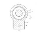
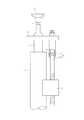
FIG. 1 is an overall configuration diagram showing a vehicle assembled with an electric telescopic adjustment type steering device according to the present invention, FIG. 2 is an overall configuration diagram showing a first embodiment of an electric telescopic adjustment type steering device according to the present invention, and FIG. Is a cross-sectional view taken along line AA in FIG. 2, FIG. 4 is a cross-sectional view taken along line BB in FIG. 3, FIG. 5 is a cross-sectional view of the main part of the present invention, and FIG. 7 and 7 are cross-sectional views along the line DD in FIG.
図1において、ステアリングコラム装置10は、ステアリングシャフト11を回動自在に支持するステアリングコラム12を有する。ステアリングシャフト11には、その後端にステアリングホイール13が装着され、ステアリングシャフト11の前端にはユニバーサルジョイント14を介して中間シャフト15が連結されている。中間シャフト15にはその前端にユニバーサルジョイント16を介してラックアンドピニオン機構等からなるステアリングギヤ17が連結されている。このステアリングギヤ17の出力軸がタイロッド18を介して転舵輪19に連結されている。 In FIG. 1, a
そして、運転者がステアリングホイール13を操舵すると、ステアリングシャフト11、ユニバーサルジョイント14、中間シャフト15、ユニバーサルジョイント16を介してその回転力がステアリングギヤ17に伝達され、ラックアンドピニオン機構で回転運動が車両幅方向の直線運動に変換されてタイロッド18を介して転舵輪19を転舵する。
なお、ステアリングコラム12の車両後方部位には、後述する電動チルト機構30及び電動テレスコ機構50を駆動するコントロールスイッチ、コンビスイッチやコラムカバー等の周辺部品Pが配設されている。When the driver steers the
In addition, peripheral parts P such as a control switch, a combination switch, a column cover, and the like for driving an
ステアリングコラム装置10は、図5に示すように、車両の水平方向に対して後ろ上がりに所定角度θだけ傾斜して配置されている。このステアリングコラム装置10はステアリングシャフト11が図5に示すようにステアリングホイール13を取付けたアウタシャフト11aと、このアウタシャフト11aにスプライン結合又はセレーション結合されて摺動自在に係合されたインナシャフト11bとで構成されている。 As shown in FIG. 5, the
また、ステアリングコラム12が図2及び図5に示すようにアウタコラム12aと、このアウタコラム12aに摺動自在に保持されたインナコラム12bとで構成され、インナコラム12bの後端部内周面に配設された転がり軸受12c及びアウタコラム12aの前端部内周面に配設された転がり軸受(不図示)によってステアリングシャフト11のアウタシャフト11aとインナシャフト11bとが回転自在に支持されている。 2 and 5, the
アウタコラム12aはそのユニバーサルジョイント14側の後端(図2において左端)が車体側部材21に取付けられたロアブラケット22にピボットピン23によって上下方向に揺動自在に支持され、ステアリングホイール13側の前端(図2において右端)が車体側部材21に取付けられアッパブラケット24に上下方向に移動自在に支持されている。 The
このアッパブラケット24は、図3に示すように、車体側部材21に取付けられる中央部が上方に膨出された膨出部24aを有する取付板部24bと、この取付板部24bの膨出部24aの左右位置から下方に延長する案内板部24c及び24dと、これら案内板部24c及び24dの下端部間を連結する底板部24eとで方形枠状に形成されている。
そして、アッパブラケット24の取付板部24b、案内板部24c,24d及び底板部24eで囲まれる案内空間24f内に前述したアウタコラム12aが挿通されている。アウタコラム12aは、図3で明らかなように、水平方向に突出する突出部があり、その端部が案内板部24c及び24dと近接対向する垂直の案内面12cを有する案内板部12d,12eが形成されている。As shown in FIG. 3, the
The
そして、案内板部12eが電動チルト機構30によって上下方向に移動可能に保持されている。電動チルト機構30は、図3に示すように、アッパブラケット24の案内板部24dの下端部に一体に形成された略方形枠状のギヤハウジング31内に抑え部材32によって固定配置した転がり軸受33と、前述したアッパブラケット24の取付板部24bの下面に配設した転がり軸受34とによって案内板部24dに沿って上下方向に延長し、且つ回転自在に支持されたねじ軸35を有する。 The
このねじ軸35には、ギヤハウジング31内の転がり軸受33近傍位置にウォームホイール36が装着され、このウォームホイール36にウォーム37が噛合されている。このウォーム37は、図4に示すように、ギヤハウジング31内に配設された転がり軸受38及び39によって回転自在に保持され、その一端が、アッパブラケット24の案内板部24dに形成された取付板部24gに固定された電動モータ40の出力軸40aにカップリング39を介して連結されている。 A
また、ギヤハウジング31のねじ軸35を挿通する挿通孔31a内にねじ軸35を覆う円筒覆体41が配設され、この円筒覆体41の先端にねじ軸35の外周面に摺接する大きな弾性を有するポリウレタン等の合成樹脂で製作されたダンパー42が配設されている。同様に、転がり軸受34の下端面にもねじ軸35の外周面に摺接するダンパー43が配設されている。 A
そして、ねじ軸35のダンパー42及び43間に、断面方形のナットホルダ44に保持されたナット45が螺合されている。このナットホルダ44はアッパブラケット24の案内板部24dに形成された上下方向に延長する案内溝46内に係合することにより、ナットホルダ44のねじ軸35における軸芯回りの回転運動が規制され、ねじ軸35の正逆回転によってナットホルダ44が上下方向に移動される。このナットホルダ44に突出形成された係合ピン47が前述したアウタコラム12aの先端に形成されたアウタコラム12aの軸方向に延長する長孔24hに係合されている。 A
したがって、電動モータ40によってウォーム37を正逆転駆動することにより、ウォームホイール36を介してねじ軸35が正逆転駆動され、これによってナットホルダ44が上下動され、アウタコラム12aがピボットピン23を中心として上下に揺動されてチルト機能を発揮することができる。
そして、ステアリングコラム12のアウタコラム12a及びインナコラム12b間に図5に示すように電動アクチュエータとしての電動テレスコ機構50が設けられている。Therefore, when the
An electric
この電動テレスコ機構50は、図5に示すように、ステアリングコラム12のアウタコラム12aのステアリングホイール13側に固定されたギヤハウジング51を有する。
このギヤハウジング51には、ステアリングコラム12の軸方向に所定距離だけ離れて対向配置された転がり軸受52及び53によってウォームホイール54が回転自在に支持されている。このウォームホイール54は、中央部の大径外周面とこの大径外周面を挟む両端側の転がり軸受52及び53が外嵌された小径外周面とを有する円筒状に形成され、大径外周面にヘリカルギヤ54aが形成されていると共に、内周面に雌ねじ54bが形成されている。As shown in FIG. 5, the electric
A
そして、ウォームホイール54のヘリカルギヤ54aには、図6に示すように、ギヤハウジング51に取付けられた電動モータ55の出力軸に連結されたウォーム56が噛合されている。ここで、ウォーム56はギヤハウジング51内に配設された転がり軸受56a及び56bによって回転自在に支持され、電動モータ55の出力軸55aにカップリング55bを介して連結されている。これらウォームホイール54及びウォーム56で減速機が構成されている。また、後述する連結ロッド58とウォームホイール54の雌ねじ部54bとで直動機構が構成されている。 As shown in FIG. 6, the
一方、ステアリングコラム12のインナコラム12bのステアリングホイール13寄り位置にギヤハウジング51と同一方向に延長し且つアウタコラム12aの端面とは距離をおいて配置された連結プレート57が取付けられ、この連結プレート57とギヤハウジング51との間に連結ロッド58が配設されている。
この連結ロッド58は、ステアリングホイール13側の連結プレート57の下端に固定された大径ロッド部58aと、この大径ロッド部58aよりは小径で外周面にウォームホイール54の雌ねじ部54bに螺合する雄ねじ部58bとを有する。On the other hand, a connecting
The connecting
そして、連結ロッド58は、その雄ねじ部58bがギヤハウジング51に回転自在に支持されたウォームホイール54の雌ねじ54bに螺合されて、連結ロッド58がステアリングコラム12の下側にステアリングコラム12の中心軸に対して所定のオフセット値Lだけ離間して中心軸と平行となるように配設されている。
また、アウタコラム12aのステアリングホイール13側端部近傍に回転阻止部材としての回転阻止プレート59が固定され、この回転阻止プレート59の下端が連結ロッド58の下側まで延長され、その延長部に図7に示すように連結ロッド58を挿通する挿通孔59aが形成されている。The connecting
Further, a
したがって、電動モータ55を正逆転駆動して、ウォーム56を介してウォームホイール54を正逆転駆動することにより、連結ロッド58をステアリングコラム12の軸方向に前後進させ、連結プレート57を介してインナコラム12bが軸方向に伸縮駆動されてテレスコ機能を発揮することができる。
次に、上記第1の実施形態の動作を説明する。Therefore, by driving the
Next, the operation of the first embodiment will be described.
今、運転者が、ステアリングコラム装置10のステアリングコラム12のチルト調整を行うには、図1に示すステアリングコラム12の車両後方部位に配設された周辺部品Pに設けられたチルト機構用のコントロールスイッチをチルトアップ方向(又はチルトダウン方向)に操作すると、電動チルト機構30の電動モータ40を例えば正転(又は逆転)駆動される。 Now, in order for the driver to adjust the tilt of the
これに応じて、ウォーム37を介してウォームホイール36を介してねじ軸35を逆転(又は正転)駆動することにより、ナット45が図3で見て上方(又は下方)に移動し、これによってナットホルダ44に形成された係合ピン47がステアリングコラム12のアウタコラム12aに形成された長孔24hに係合しているので、アウタコラム12aがピボットピン23を中心として上方(下方)に回動し、チルトアップ(又はチルトダウン)調整を行うことができる。 In response to this, by driving the
また、運転者が、ステアリングコラム装置10のステアリングコラムのテレスコ調整を行うには、図1に示すステアリングコラム12の車両後方部位に配設された周辺部品Pに設けられたテレスコ機構用のコントロールスイッチを伸張方向(又は収縮方向)に操作すると、電動テレスコ機構50の電動モータ55が例えば正転(又は逆転)駆動される。
これによって、ウォーム56を介してウォームホイール54が正転(又は逆転)駆動され、これによって連結ロッド58がステアリングホイール13側(又はステアリングホイール13とは反対側)に移動する。In addition, in order for the driver to perform telescopic adjustment of the steering column of the
As a result, the
このため、連結ロッド58の大径ロッド部58aに固定された連結プレート57を介してインナコラム12bがアウタコラム12aから引き出されて(又はインナコラム12bがアウタコラム12a内に挿入されて)ステアリングコラム12が伸張(又は収縮)してテレスコ調整を行うことができる。
このとき、インナコラム12bの移動に伴って、ステアリングシャフト11のアウタシャフト11aがインナシャフト11bに対して移動する。For this reason, the
At this time, along with the movement of the
このように、電動テレスコ機構50によってステアリングコラム12のテレスコ調整を行う場合に、ステアリングコラム12を構成するアウタコラム12a及びインナコラム12b間に両者を相対回転させる回転力が作用されたときには、アウタコラム12a及びインナコラム12bが相対回転しようとするが、連結ロッド58の大径ロッド部58aの端部がインナコラム12bの外周面に固定された連結プレート57に固定され、この大径ロッド部58aの雄ねじ部58b側がアウタコラム12aの外周面に固定された回転阻止プレート59の挿通孔59aに挿通されているので、アウタコラム12a及びインナコラム12bが相対回転しようとしても両者が連結プレート57、連結ロッド58の大径ロッド部58a及び回転阻止プレート59を介して連結されているので、これら連結プレート57、連結ロッド58の大径ロッド部58a及び回転阻止プレート59で相対回転阻止機能を発揮して、アウタコラム12a及びインナコラム12bの相対回転を確実に阻止することができる。 Thus, when the telescopic adjustment of the
このように、アウタコラム12a及びインナコラム12bの相対回転が阻止されるので、電動アクチュエータとしての電動テレスコ機構50の直動機構を構成する連結ロッド58の雄ねじ部58b、ウォームホイール54及びウォーム56に相対回転力による捻じれ力が作用することはなく、ウォームホイール54とウォーム56との噛合状態を良好に維持することができ、電動モータ55の負荷が増加することを確実に阻止することができる。 Thus, since the relative rotation of the
なお、上記第1の実施形態においては、回転阻止プレート59に連結ロッド58の大径ロッド部58aを挿通する挿通孔59aを形成した場合について説明したが、これに限定されるものではなく、挿通孔59aに代えて、図8に示すように、連結ロッド58の大径ロッド部58aに上方側から係合する係合凹部59bを形成するようにしてもよい。さらには、図9に示すように、連結ロッド58の大径ロッド部58aを断面方形に形成し、この大径ロッド部58aに上方側から係合する係合凹部59cを形成するようにしてもよく。要は回転阻止プレート59に連結ロッド58の大径ロッド部58a左右両側部に係合してアウタコラム12a及びインナコラム12bの相対回転を阻止することができる側壁が形成されていればよい。 In the first embodiment, the case where the
また、上記実施形態においては、回転阻止プレート59に挿通孔59aを形成した場合について説明したが、これに限定されるものではなく、図10に示すように、挿通孔59aの連結ロッド58の大径ロッド部58aに接触する内周面に例えば合成樹脂性の低摩擦抵抗のスリーブ59dを装着したり、内周面に低摩擦係数のコーティング材をコーティングしたブッシュを適用するようにしたりしてもよい。この場合には、スリーブ59d又はブッシュによって連結ロッド58の大径ロッド部58aの摺動が阻害されることなく、より円滑な摺動を確保することができる。 In the above embodiment, the case where the
また、上記第1の実施形態においては、ステアリングコラム装置10の下側に電動テレスコ機構50を配設した場合について説明したが、これに限定されるものではなく、ステアリングコラム装置の断面図を表す図11に示すように、電動テレスコ機構50をステアリングコラム装置10の側面側に配設するようにしても前述した第1の実施形態と同様の作用効果を得ることができ、電動テレスコ機構50の配置位置はステアリングコラム12の周囲であれば任意の位置に配置することができる。 In the first embodiment, the case where the electric
次に、本発明の第2の実施形態をステアリングコラム装置の縦断面図を表す図12について説明する。
この第2の実施形態では、連結ロッド58の中間部に二次衝突による衝撃荷重が伝達されたときに収縮する収縮部73を形成するようにしたものである。
すなわち、第2の実施形態では、図12に示すように、連結ロッド58が、車両後方側端部が連結プレート57に固定された筒状のアウタロッド部71と、このアウタロッド部71に収縮可能に嵌挿され、車両前方側端部がウォームホイール54に螺合される雄ねじ部58gを形成したインナロッド部72とで構成され、インナロッド部72をアウタロッド部71に嵌挿した部位が収縮部73とされている。Next, a second embodiment of the present invention will be described with reference to FIG. 12 showing a longitudinal sectional view of a steering column device.
In the second embodiment, a
That is, in the second embodiment, as shown in FIG. 12, the connecting
そして、この収縮部73に断面が円周方向に凹凸を繰り返す波形に成形された薄い板バネ材をリング状に形成した連結保持部材74が配設されている。この連結保持部材74は、アウタロッド部71及びインナロッド部72の双方に接触して、常時はアウタロッド部71及びインナロッド部72の収縮を阻止するが、所定以上の衝撃荷重が伝達されたときにアウタロッド部71及びインナロッド部72の収縮を許容する。この連結保持部材74のアウタロッド部71及びインナロッド部72の相対移動を許容するコラプス荷重が例えば約2kN以上に設定されている。 The
この第2の実施形態によると、ステアリングホイール13に衝撃荷重Fが作用されていない通常時には、電動モータ55の回転駆動によるウォーム56及びウォームホイール54を介して連結ロッド58が軸方向に移動する際に、連結保持部材74によってアウタロッド部71及びインナロッド部72が両者間に滑りがない状態に一体に連結されて軸方向に移動し、これに応じて連結プレート57を介してインナコラム12bが軸方向に移動して、テレスコ動作を行うことができる。 According to the second embodiment, when the impact load F is not applied to the
しかしながら、ステアリングホイール13に衝撃荷重Fが作用することにより、ステアリングコラム装置10のインナコラム12bに衝撃荷重Fのコラム軸方向分力Fxが作用し、このコラム軸方向分力Fxが連結プレート57を介して連結ロッド58に伝達され、これが設定されたコプラス荷重以上となると、アウタロッド部71とインナロッド部72との相対収縮を許容して、アウタロッド部71及びインナロッド部72に連結保持部材74が弾性接触したまま車両前方側に摺動するので、衝撃エネルギ吸収を確実に行うことができる。 However, when an impact load F acts on the
なお、上記第2の実施形態においては、連結プレート57とアウタロッド部71とを一体に形成した場合について説明したが、これに限定されるものではなく、アウタロッド部71を、ピボットピンを介して連結プレート57に連結するようにしてもよく、この場合には、ステアリングホイール13に衝撃荷重Fが作用したときに、連結プレート57及び連結ロッド58のアウタロッド部71との間がピボット結合されているので、連結プレート57に曲げモーメントMが作用することを抑制することができ、連結保持部材74による離脱荷重を所定のコプラス荷重に安定させることができると共に、連結ロッド58のアウタロッド部71及びインナロッド部72間の収縮時の衝撃エネルギ吸収を正確に行うことができる。 In the second embodiment, the case where the connecting
また、上記第1及び第2の実施形態においては、ステアリングコラム12のアウタコラム12aを車体側部材21に固定した場合について説明したが、これに限定されるものではなく、インナコラム12bをロアブラケット22及びアッパブラケット24で車体側部材21に取付け、アウタコラム12aにステアリングホイール13を取付けるようにしてもよい。 In the first and second embodiments, the case where the
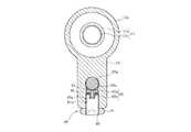
次に、本発明の第3の実施形態をステアリングコラム装置の縦断面図を表す図13及び図13のG−G線上の断面図を表す図14について説明する。
この第3の実施形態は、ステアリングコラム装置10のアウタコラム12a及びインナコラム12bを入れ換えると共に、連結プレート57と連結ロッド58との間に収縮部を形成し、この収縮部に、コラム軸方向分力Fxがコラプス荷重以上であるときに破断する樹脂ピンを圧入するようにしたものである。Next, a third embodiment of the present invention will be described with reference to FIG. 13 representing a longitudinal sectional view of a steering column device and FIG. 14 representing a sectional view along the line GG in FIG.
In the third embodiment, the
すなわち、第3の実施形態では、図13に示すように、ステアリングコラム12のアウタコラム12aがステアリングホイール13側に配置され、このインナコラム12bに対してアウタコラム12aが摺動可能に配設されている。
そして、アウタコラム12a及びインナコラム12b間に図13に示すように電動アクチュエータとしての電動テレスコ機構50が設けられている。That is, in the third embodiment, as shown in FIG. 13, the
An electric
この電動テレスコ機構50は、前述した第1の実施形態と同様に、アウタコラム12aに固定されたギヤハウジング51を有し、このギヤハウジング51内に転がり軸受52及び53によって回転自在に指示されたウォームホイール54及びこのウォームホイール54に噛合し、且つ電動モータ55によって回転駆動されるウォーム56が配設されている。 This electric
そして、ウォームホイール54の内周面に形成された雌ねじ54bに連結ロッド58の一方の端部に形成された雄ねじ58bが螺合され、連結ロッド58の他方の端部に形成された大径ロッド部58aがインナコラム12bに対して軸方向に移動できないように固定された平板状の連結プレート57に形成された挿通孔57oに挿通されて収縮部80が形成されている。 The
また、連結ロッド58の大径ロッド部58aがアウタコラム12aの前端面に固定された回転阻止プレート59の挿通孔59aに挿通されている。
そして、連結プレート57に、図14に示すように、その下面側から挿通孔57oを通って上方に延長する嵌合孔57pが形成され、この嵌合孔57pに対応する連結ロッド58の大径ロッド部58aに、嵌合孔57pに連通する嵌合孔58mが形成され、両嵌合孔57p及び58m内に所定のコプラス荷重で破断する合成樹脂ピン81が嵌合されている。The large-
Then, as shown in FIG. 14, the
この第3の実施形態によると、ステアリングホイール13に二次衝突時の衝撃荷重Fが作用していない通常状態では、合成樹脂ピン81によって連結プレート57及び連結ロッド58が連結されているので、電動テレスコ機構50の電動モータ55を正逆転駆動することにより、連結ロッド58が進退されてアウタコラム12aがインナコラム12bに対して進退することにより、ステアリングホイール13のテレスコ位置を調整することができる。 According to the third embodiment, since the connecting
この通常状態からステアリングホイール13に図13に示すように二次衝突時の衝撃荷重Fが作用することになると、この衝撃荷重Fのコラム軸方向分力Fxがアウタコラム12a、電動テレスコ機構50を介して連結ロッド58に伝達される。このとき、連結ロッド58と連結プレート57との間に伝達されるコラム軸方向分力Fxが合成樹脂ピン81で設定された所定のコラプス荷重以上となると、合成樹脂ピン81が破断して連結ロッド58の車両前方側への移動が許容される。 When the impact load F at the time of the secondary collision is applied to the
この第3の実施形態でも、回転阻止プレート59が設けられ、その挿通孔59aに連結ロッド58の大径ロッド部58aが挿通されているので、連結プレート57、連結ロッド58の大径ロッド部58a及び回転阻止プレート59によって、アウタコラム12a及びインナコラム12bの相対回転を確実に阻止することができ、連結ロッド58の捻じれを防止することができるので、電動テレスコ機構50の電動モータ55の負荷が増加することを確実に防止することができる。 Also in the third embodiment, the
なお、上記第1〜第3の実施形態においては、回転阻止プレート59をアウタコラム12aに固定する場合について説明したが、これに限定されるものではなく、回転阻止プレート59をアウタコラム12aに一体成形するようにしてもよい。
次に、本発明の第4の実施形態をステアリングコラム装置の縦断面図を表す図15及び図15のH−H線上の断面図を表す図16について説明する。In the first to third embodiments, the case where the
Next, a fourth embodiment of the present invention will be described with reference to FIG. 15 representing a longitudinal sectional view of a steering column device and FIG. 16 representing a sectional view taken along the line HH in FIG.
すなわち、第4の実施形態では、図15に示すように、回転阻止プレート59がアウタコラム12aに一体に形成されており、この回転阻止プレート59に図16に示すように、ガタ抑制機構80が形成されていることを除いては前述した第1の実施形態と同様の構成を有し、図5との対応部分には同一符号を付し、その詳細説明はこれを省略する。
ここで、ガタ抑制機構80は、図16に示すように、回転阻止プレート59の下側から上方に向けて回転阻止プレート59のコラム中心線と連結ロッド58の中心線とを通る平面に沿って挿通孔59aに達する挿通孔81が形成されている。That is, in the fourth embodiment, as shown in FIG. 15, the
Here, as shown in FIG. 16, the
この挿通孔81内に、連結ロッド58の外周面に接触し、中心部に透孔を有する円板部82aとこの円板部82aの下面中央部から下方に突出する円筒部82bとで断面T字状に形成された押圧ブロック82が挿入されている。そして、押圧ブロック82が挿通孔81に形成された雌ねじ81aに螺合する雄ねじ83の上端に形成された案内凹部83a内に上下動可能に保持され、この雄ねじ83の回転阻止プレート59より下方に突出する端部に止めナット84が螺合されている。また、雄ねじ83の上端面と押圧ブロック82の円板部82aの裏面との間に皿ばね85が介挿され、この皿ばね85によって押圧ブロック82を介して連結ロッド58を挿通孔59aの上面側に付勢する。 In this
この第4の実施形態によると、回転阻止プレート59の挿通孔59a内に連結ロッド58の大径部58aを挿通した状態で、押圧ブロック82を皿ばね85を介して保持した雄ねじ83を挿通孔81に形成した雌ねじ81aに螺合させて挿通孔59内に押し込むことにより、押圧ブロック82で皿ばね85による付勢力で連結ロッド58の大径部58aを変位させて、大径部58aを挿通孔59aの上面側に接触させることができる。このため、連結ロッド58の大径部58aと挿通孔59aとの半径方向のガタを確実に抑制することができる。 According to the fourth embodiment, the
しかも、ガタ抑制機構80が連結ロッド58に対して軸直角方向の垂直方向に配設されているので、回転阻止プレート59の左右方向の幅を狭くすることができる。
次に、本発明の第5の実施形態を図16と同様の断面図である図17について説明する。
すわなち、この第5の実施形態では、図17に示すように、回転阻止プレート59に形成したガタ抑制機構80を垂直方向に配設する場合に代えて水平方向即ちコラム中心線及び連結ロッド中心線を通る平面と直交する方向に配設したことを除いては第4の実施形態と同様の構成を有し、図16との対応部分には同一符号を付し、その詳細説明はこれを省略する。In addition, since the
Next, a fifth embodiment of the present invention will be described with reference to FIG. 17, which is a sectional view similar to FIG.
That is, in the fifth embodiment, as shown in FIG. 17, instead of the case where the
この第5の実施形態によると、ガタ抑制機構80が水平方向に配設されているので、雄ねじ83を挿通孔81の雌ねじ81aに螺合させて挿通孔81内に押し込むことにより、皿バネ85を介して押圧ブロック82で連結ロッド58の大径部58aを水平方向に付勢するので、連結ロッド58の大径部58aが挿通孔59aの例えば左側部に接触する状態となり、連結ロッド58の大径部58aと挿通孔59aとの間のガタを確実に抑制することができる。 According to the fifth embodiment, since the
このとき、連結ロッド58の大径部58aを水平方向に変位させるので、その変位の前後でコラム中心線と連結ロッド58の中心線との間の芯間距離Xは変化せず、作動フリクションの増加を確実に抑制することができる。
因みに、前述した第4の実施形態のように、ガタ抑制機構80を垂直方向に配設する場合には、連結ロッド58をステアリングコラム12に向けて変位させるので、連結ロッドの変位の前後でコラム中心線と連結ロッド58の中心線との間の芯間距離Xが変化するため、作動フリクションが増加して好ましくない影響を与える可能性があるが、第5の実施形態のようにガタ抑制機構80を水平方向に配設する場合には、上述したように、芯間距離Xが変化せず、作動フリクションの増加を抑制することができる。At this time, since the large-
Incidentally, as in the above-described fourth embodiment, when the
なお、上記第4及び第5の実施形態においては、回転阻止プレート59がアウタコラム12aに一体成形されている場合について説明したが、これに限定されるものではなく、前述した第1〜第3の実施形態のように、アウタコラム12aとは別体で構成するようにしてもよい。
また、第4及び第5の実施形態においては、回転阻止プレート59にガタ抑制機構80を垂直方向及び水平方向に配置する場合について説明したが、これに限定されるものではなく、ガタ抑制機構80の配設方向は任意に設定することができる。In the fourth and fifth embodiments, the case where the
In the fourth and fifth embodiments, the description has been given of the case where the
さらに、上記第1〜第5の実施形態においては、ステアリングコラム12の下側に連結ロッド58を配設した場合について説明したが、これに限定されるものではなく、連結ロッド58はステアリングコラム12と平行であればステアリングコラム12の円周上の任意の方向に配設することができる。
さらにまた、上記第1〜第5の実施形態においては、電動テレスコ機構50にのみ収縮部73を設けた場合について説明したが、これに限定されるものではなく、電動チルト機構30のナットホルダ44とナット45との間に所定のコラプス荷重以上の二次衝突時における衝撃荷重Fのコラム軸直角方向分力Fyが作用したときに収縮する収縮部を形成するようにしてもよい。Further, in the first to fifth embodiments, the case where the connecting
Furthermore, in the first to fifth embodiments, the case where the
また、上記第1〜第3の実施形態においては、電動チルト機構30を備えている場合について説明したが、これに限定されるものではなく、電動チルト機構30を省略して、電動テレスコ機構50のみを設けるようにしてもよい。 Moreover, although the case where the
10…ステアリングコラム装置、11…ステアリングシャフト、11a…アウタシャフト、11b…インナシャフト、12…ステアリングコラム、12a…アウタコラム、12b…インタコラム、13…ステアリングホイール、14,16…ユニバーサルジョイント、15…中間シャフト、17…ステアリングギヤ、18…タイロッド、19…転舵輪、21…車体側部材、22…ロアブラケット、24…アッパブラケット、30…チルト機構、50…テレスコ機構、51…ギヤハウジング、54…ウォームホイール、55…電動モータ、56…ウォーム、57…連結プレート、58…連結ロッド、58a…大径ロッド部、59…回転阻止プレート、59a…挿通孔、71…アウタロッド部、72…インナロッド部、74…連結保持部材、80…収縮部、81…合成樹脂ピン DESCRIPTION OF
Claims (5)
Translated fromJapanese前記電動アクチュエータは、前記アウタコラム及びインナコラムの相対回転を阻止する回転阻止部材を備えていることを特徴とする電動テレスコ調整式ステアリング装置。A steering column that has an outer column and an inner column that are relatively telescopically connected, and that rotatably supports a steering shaft to which a steering wheel is attached, one end of the steering column and the other end An electric telescopic adjustment type steering apparatus that is attached to the inner column and includes an electric actuator that extends and contracts the outer column and the inner column,
The electric actuator is provided with a rotation preventing member that prevents relative rotation of the outer column and the inner column.
Priority Applications (4)
| Application Number | Priority Date | Filing Date | Title |
|---|---|---|---|
| JP2006269357AJP2008087582A (en) | 2006-09-29 | 2006-09-29 | Electric telescopic adjustment type steering device |
| EP07013624AEP1905664A3 (en) | 2006-09-29 | 2007-07-11 | Electrically adjustable telescopic steering apparatus |
| CNA2007101305825ACN101152874A (en) | 2006-09-29 | 2007-07-18 | Telescopically adjustable electric steering |
| US11/779,388US20080079253A1 (en) | 2006-09-29 | 2007-07-18 | Telescopic adjusting electric power steering apparatus |
Applications Claiming Priority (1)
| Application Number | Priority Date | Filing Date | Title |
|---|---|---|---|
| JP2006269357AJP2008087582A (en) | 2006-09-29 | 2006-09-29 | Electric telescopic adjustment type steering device |
Publications (1)
| Publication Number | Publication Date |
|---|---|
| JP2008087582Atrue JP2008087582A (en) | 2008-04-17 |
Family
ID=38779724
Family Applications (1)
| Application Number | Title | Priority Date | Filing Date |
|---|---|---|---|
| JP2006269357APendingJP2008087582A (en) | 2006-09-29 | 2006-09-29 | Electric telescopic adjustment type steering device |
Country Status (4)
| Country | Link |
|---|---|
| US (1) | US20080079253A1 (en) |
| EP (1) | EP1905664A3 (en) |
| JP (1) | JP2008087582A (en) |
| CN (1) | CN101152874A (en) |
Cited By (2)
| Publication number | Priority date | Publication date | Assignee | Title |
|---|---|---|---|---|
| JP2009240369A (en)* | 2008-03-28 | 2009-10-22 | Fukuda Denshi Co Ltd | Gel for medical use |
| JP2018047809A (en)* | 2016-09-21 | 2018-03-29 | アイシン精機株式会社 | Vehicle steering device |
Families Citing this family (39)
| Publication number | Priority date | Publication date | Assignee | Title |
|---|---|---|---|---|
| JP4483914B2 (en)* | 2007-09-06 | 2010-06-16 | トヨタ自動車株式会社 | Steering column device |
| CN101817363B (en)* | 2009-12-30 | 2012-12-12 | 浙江双辉剑机械有限公司 | Electric type power steering device |
| DE102010020088B4 (en)* | 2010-05-10 | 2013-06-27 | Thyssenkrupp Presta Aktiengesellschaft | Method and device for controlling a controllable energy absorber |
| JP5513282B2 (en)* | 2010-06-29 | 2014-06-04 | 富士機工株式会社 | Electric telescopic steering device |
| JP5674367B2 (en)* | 2010-07-27 | 2015-02-25 | 富士機工株式会社 | Steering column device |
| CN102452411A (en)* | 2010-10-22 | 2012-05-16 | 比亚迪股份有限公司 | Device for automatically adjusting steering wheel |
| JP5382066B2 (en)* | 2011-06-03 | 2014-01-08 | 日本精工株式会社 | Steering device |
| JP5641057B2 (en)* | 2011-12-20 | 2014-12-17 | 日本精工株式会社 | Steering device |
| DE102012000635A1 (en) | 2012-01-14 | 2013-07-18 | Daimler Ag | Spindle drive for height adjustment of an electrically adjustable steering column |
| WO2013176191A1 (en)* | 2012-05-25 | 2013-11-28 | 日本精工株式会社 | Position adjustment device for electric steering wheel |
| JP6067484B2 (en)* | 2013-05-29 | 2017-01-25 | 富士機工株式会社 | Steering column device |
| WO2015064345A1 (en)* | 2013-10-31 | 2015-05-07 | 日本精工株式会社 | Steering device |
| CN103612657A (en)* | 2013-12-03 | 2014-03-05 | 顺达(芜湖)汽车饰件有限公司 | Movable type steering wheel of automobile |
| US9834245B2 (en)* | 2014-12-18 | 2017-12-05 | Nsk Ltd. | Steering device |
| US10351159B2 (en) | 2015-05-01 | 2019-07-16 | Steering Solutions Ip Holding Corporation | Retractable steering column with a radially projecting attachment |
| US10343706B2 (en) | 2015-06-11 | 2019-07-09 | Steering Solutions Ip Holding Corporation | Retractable steering column system, vehicle having the same, and method |
| US11560169B2 (en) | 2015-06-11 | 2023-01-24 | Steering Solutions Ip Holding Corporation | Retractable steering column system and method |
| CN106256651B (en) | 2015-06-16 | 2019-06-04 | 操纵技术Ip控股公司 | Retractable steering column assembly and method |
| DE102016111473A1 (en) | 2015-06-25 | 2016-12-29 | Steering Solutions Ip Holding Corporation | STATIONARY STEERING WHEEL ASSEMBLY AND METHOD |
| DE102015216326B4 (en)* | 2015-08-26 | 2016-09-08 | Thyssenkrupp Ag | Motor-adjustable steering column for a motor vehicle |
| DE102016200649B4 (en)* | 2016-01-19 | 2019-09-19 | Thyssenkrupp Ag | Electrically longitudinally adjustable steering column for a motor vehicle |
| CN107521547B (en)* | 2016-06-21 | 2020-03-10 | 操纵技术Ip控股公司 | Self-locking telescopic actuator for steering column assembly |
| US10457313B2 (en) | 2016-06-28 | 2019-10-29 | Steering Solutions Ip Holding Corporation | ADAS wheel locking device |
| US10363958B2 (en) | 2016-07-26 | 2019-07-30 | Steering Solutions Ip Holding Corporation | Electric power steering mode determination and transitioning |
| US10189496B2 (en) | 2016-08-22 | 2019-01-29 | Steering Solutions Ip Holding Corporation | Steering assembly having a telescope drive lock assembly |
| US10351160B2 (en) | 2016-11-30 | 2019-07-16 | Steering Solutions Ip Holding Corporation | Steering column assembly having a sensor assembly |
| US10370022B2 (en) | 2017-02-13 | 2019-08-06 | Steering Solutions Ip Holding Corporation | Steering column assembly for autonomous vehicle |
| US10385930B2 (en) | 2017-02-21 | 2019-08-20 | Steering Solutions Ip Holding Corporation | Ball coupling assembly for steering column assembly |
| DE102017120669B4 (en)* | 2017-09-07 | 2025-03-20 | Zf Automotive Germany Gmbh | Steering column assembly for a motor vehicle and steering system |
| EP3492343B1 (en)* | 2017-12-01 | 2020-07-15 | TRW Steering Systems Poland Sp z o. o. | Steering column assembly |
| DE102018202795A1 (en)* | 2018-02-23 | 2019-08-29 | Thyssenkrupp Ag | Steering column for a motor vehicle |
| DE102018212738A1 (en)* | 2018-07-31 | 2020-02-06 | Brose Fahrzeugteile Gmbh & Co. Kommanditgesellschaft, Coburg | Steering device adjustable by electric motor |
| US10974756B2 (en) | 2018-07-31 | 2021-04-13 | Steering Solutions Ip Holding Corporation | Clutch device latching system and method |
| DE102018220175A1 (en)* | 2018-11-23 | 2020-05-28 | Thyssenkrupp Ag | Steering column for a motor vehicle |
| DE102019201619A1 (en)* | 2019-02-07 | 2020-08-13 | Robert Bosch Gmbh | Adjustable steering column for a motor vehicle |
| GB2586811B (en)* | 2019-09-03 | 2023-08-30 | Zf Automotive Uk Ltd | Steering column assembly for a vehicle |
| US11390313B2 (en)* | 2020-04-30 | 2022-07-19 | Nsk Ltd. | Electrically adjustable steering column |
| CN112590800B (en)* | 2020-12-14 | 2022-03-25 | 浙江梵隆汽车部件有限公司 | Intelligent recognition steering wheel based on multi-sensor fatigue driving and recognition method thereof |
| WO2024088458A1 (en)* | 2022-10-28 | 2024-05-02 | Schaeffler Technologies AG & Co. KG | Adjusting unit of a steering column |
Family Cites Families (18)
| Publication number | Priority date | Publication date | Assignee | Title |
|---|---|---|---|---|
| US4602520A (en)* | 1983-06-23 | 1986-07-29 | Aisin Seiki Kabushiki Kaisha | Telescopic steering column assembly |
| US4785684A (en)* | 1986-09-30 | 1988-11-22 | Aisin Seiki Kabushiki Kaisha | Vehicle steering mechanism |
| JP2638871B2 (en)* | 1988-01-26 | 1997-08-06 | アイシン精機株式会社 | Steering device |
| DE3822460C1 (en)* | 1988-07-02 | 1990-01-04 | Daimler-Benz Aktiengesellschaft, 7000 Stuttgart, De | |
| FR2662986B1 (en)* | 1990-06-07 | 1994-11-18 | Nacam | DEVICE FOR ADJUSTING THE POSITION OF AN ADJUSTABLE STEERING COLUMN. |
| DE4106735A1 (en)* | 1991-03-02 | 1992-09-03 | Porsche Ag | STEERING COLUMN FOR MOTOR VEHICLES |
| US5520416A (en)* | 1994-10-03 | 1996-05-28 | Ford Motor Company | Power tilt, telescoping and internally collapsible steering column |
| DE19524196C1 (en)* | 1995-07-03 | 1996-11-14 | Daimler Benz Ag | Longitudinal adjustment device on a jacketed telescope of a steering spindle in a motor vehicle |
| DE19654273A1 (en)* | 1995-12-26 | 1997-07-03 | Aisin Seiki | Steering wheel position adjuster for vehicle with manual steering |
| US5911789A (en)* | 1997-08-13 | 1999-06-15 | General Motors Corporation | Linear actuator for motor vehicle steering column |
| JP3612971B2 (en)* | 1997-12-03 | 2005-01-26 | 日本精工株式会社 | Shock absorbing steering column device |
| DE19812179C1 (en)* | 1998-03-19 | 1999-08-19 | Daimler Chrysler Ag | Vehicle steering column assembly to absorb impact energy on a collision |
| DE19962494A1 (en)* | 1998-12-25 | 2000-07-06 | Nsk Ltd | Automatic steering column adjusting device has steering shaft position detectors and electrical shaft angle and telescopic length actuators |
| JP2001199350A (en)* | 2000-01-17 | 2001-07-24 | Toyota Motor Corp | Vehicle steering device |
| DE10203917C1 (en)* | 2002-01-31 | 2003-07-24 | Daimler Chrysler Ag | Automobile steering column has relatively sliding inner and outer mantle sleeves and intermediate setting device |
| JP2003276616A (en) | 2002-03-25 | 2003-10-02 | Nsk Ltd | Steering device |
| DE10259596B3 (en)* | 2002-12-19 | 2004-05-13 | Daimlerchrysler Ag | Automobile steering column assembly incorporating telescopic components for preventing onjury to driver in crash situation |
| JP2007030527A (en)* | 2005-02-17 | 2007-02-08 | Nsk Ltd | Electric position adjustment device for steering wheel |
- 2006
- 2006-09-29JPJP2006269357Apatent/JP2008087582A/enactivePending
- 2007
- 2007-07-11EPEP07013624Apatent/EP1905664A3/ennot_activeWithdrawn
- 2007-07-18CNCNA2007101305825Apatent/CN101152874A/enactivePending
- 2007-07-18USUS11/779,388patent/US20080079253A1/ennot_activeAbandoned
Cited By (2)
| Publication number | Priority date | Publication date | Assignee | Title |
|---|---|---|---|---|
| JP2009240369A (en)* | 2008-03-28 | 2009-10-22 | Fukuda Denshi Co Ltd | Gel for medical use |
| JP2018047809A (en)* | 2016-09-21 | 2018-03-29 | アイシン精機株式会社 | Vehicle steering device |
Also Published As
| Publication number | Publication date |
|---|---|
| EP1905664A2 (en) | 2008-04-02 |
| EP1905664A3 (en) | 2009-04-22 |
| CN101152874A (en) | 2008-04-02 |
| US20080079253A1 (en) | 2008-04-03 |
Similar Documents
| Publication | Publication Date | Title |
|---|---|---|
| JP2008087582A (en) | Electric telescopic adjustment type steering device | |
| CN103857581B (en) | The electrical position control apparatus of steering handwheel | |
| JP5765439B2 (en) | Steering device | |
| JP2009197818A (en) | Telescopic shaft and steering device equipped with telescopic shaft | |
| JP2012245810A (en) | Rack shaft supporting device and vehicle steering device | |
| JP5338854B2 (en) | Steering device | |
| JP5082913B2 (en) | Electric tilt type steering device | |
| JP5338844B2 (en) | Electric steering device | |
| JP2008024229A (en) | Electric telescopic adjustment type steering device | |
| JP2008087531A (en) | Electric telescopic adjustment type steering device | |
| JP2007203947A (en) | Worm speed reducer for electric power steering device and electric power steering device incorporating the same | |
| JP4876739B2 (en) | Vehicle steering device | |
| KR102106287B1 (en) | Steer-by-wire Type Power Steering Apparatus | |
| JP2007069868A (en) | Steering device shaft joint structure and steering device | |
| JP2009120133A (en) | Steering device | |
| JP4507974B2 (en) | Steering device | |
| JP2008087583A (en) | Steering device and method for assembling steering device | |
| JP4483459B2 (en) | Electric steering column device | |
| JP2008007035A (en) | Electric telescopic adjustment type steering device | |
| JP2008296752A (en) | Electric telescopic adjustment type steering device | |
| JP2008094129A (en) | Electric tilt type steering device | |
| JP5233246B2 (en) | Electric telescopic adjustment type steering device | |
| JP2008074126A (en) | Electric telescopic adjustment type steering device | |
| JP2008265419A (en) | Support structure for vehicle steering column | |
| JP4900679B2 (en) | Center take-off type steering device |
Legal Events
| Date | Code | Title | Description |
|---|---|---|---|
| RD01 | Notification of change of attorney | Free format text:JAPANESE INTERMEDIATE CODE: A7421 Effective date:20090130 |