JP2008086827A - Plate - Google Patents
PlateDownload PDFInfo
- Publication number
- JP2008086827A JP2008086827AJP2007335762AJP2007335762AJP2008086827AJP 2008086827 AJP2008086827 AJP 2008086827AJP 2007335762 AJP2007335762 AJP 2007335762AJP 2007335762 AJP2007335762 AJP 2007335762AJP 2008086827 AJP2008086827 AJP 2008086827A
- Authority
- JP
- Japan
- Prior art keywords
- plate
- bone screw
- bone
- screw
- fixation
- Prior art date
- Legal status (The legal status is an assumption and is not a legal conclusion. Google has not performed a legal analysis and makes no representation as to the accuracy of the status listed.)
- Granted
Links
- 210000000988bone and boneAnatomy0.000claimsabstractdescription377
- 238000003780insertionMethods0.000claimsabstractdescription31
- 230000037431insertionEffects0.000claimsabstractdescription31
- 230000007246mechanismEffects0.000abstractdescription11
- 238000007906compressionMethods0.000description101
- 230000006835compressionEffects0.000description100
- 239000002131composite materialSubstances0.000description35
- 238000000034methodMethods0.000description25
- 238000007747platingMethods0.000description24
- 239000000463materialSubstances0.000description17
- 230000036961partial effectEffects0.000description15
- 238000001356surgical procedureMethods0.000description12
- 208000007623LordosisDiseases0.000description9
- 238000005553drillingMethods0.000description9
- 239000007943implantSubstances0.000description9
- 230000008468bone growthEffects0.000description8
- 230000006378damageEffects0.000description8
- 230000033001locomotionEffects0.000description8
- 238000010079rubber tappingMethods0.000description8
- 230000008569processEffects0.000description6
- 208000027418Wounds and injuryDiseases0.000description5
- 238000004873anchoringMethods0.000description5
- 210000004872soft tissueAnatomy0.000description5
- 238000009434installationMethods0.000description4
- 238000004519manufacturing processMethods0.000description4
- 230000001737promoting effectEffects0.000description4
- 239000007787solidSubstances0.000description4
- 239000010935stainless steelSubstances0.000description4
- 229910001220stainless steelInorganic materials0.000description4
- 239000000126substanceSubstances0.000description4
- RTAQQCXQSZGOHL-UHFFFAOYSA-NTitaniumChemical compound[Ti]RTAQQCXQSZGOHL-UHFFFAOYSA-N0.000description3
- 238000013461designMethods0.000description3
- 230000004048modificationEffects0.000description3
- 238000012986modificationMethods0.000description3
- 230000017074necrotic cell deathEffects0.000description3
- 230000035515penetrationEffects0.000description3
- 238000003786synthesis reactionMethods0.000description3
- 239000010936titaniumSubstances0.000description3
- 229910052719titaniumInorganic materials0.000description3
- 230000004913activationEffects0.000description2
- 230000002411adverseEffects0.000description2
- 230000015572biosynthetic processEffects0.000description2
- 238000007796conventional methodMethods0.000description2
- 230000001054cortical effectEffects0.000description2
- 230000000994depressogenic effectEffects0.000description2
- 238000004049embossingMethods0.000description2
- 230000004927fusionEffects0.000description2
- 229910052588hydroxylapatiteInorganic materials0.000description2
- 208000014674injuryDiseases0.000description2
- 230000001788irregularEffects0.000description2
- 230000000670limiting effectEffects0.000description2
- 238000002595magnetic resonance imagingMethods0.000description2
- 230000002188osteogenic effectEffects0.000description2
- XYJRXVWERLGGKC-UHFFFAOYSA-Dpentacalcium;hydroxide;triphosphateChemical compound[OH-].[Ca+2].[Ca+2].[Ca+2].[Ca+2].[Ca+2].[O-]P([O-])([O-])=O.[O-]P([O-])([O-])=O.[O-]P([O-])([O-])=OXYJRXVWERLGGKC-UHFFFAOYSA-D0.000description2
- 238000002601radiographyMethods0.000description2
- 230000002829reductive effectEffects0.000description2
- 230000008439repair processEffects0.000description2
- 230000004044responseEffects0.000description2
- 238000007493shaping processMethods0.000description2
- 210000000278spinal cordAnatomy0.000description2
- 210000001519tissueAnatomy0.000description2
- 208000006386Bone ResorptionDiseases0.000description1
- 102000004190EnzymesHuman genes0.000description1
- 108090000790EnzymesProteins0.000description1
- 229910001069Ti alloyInorganic materials0.000description1
- 239000002253acidSubstances0.000description1
- 230000010256bone depositionEffects0.000description1
- 230000024279bone resorptionEffects0.000description1
- 239000001506calcium phosphateSubstances0.000description1
- 238000005266castingMethods0.000description1
- 239000000919ceramicSubstances0.000description1
- 230000008859changeEffects0.000description1
- 238000001311chemical methods and processMethods0.000description1
- 238000006243chemical reactionMethods0.000description1
- 230000000295complement effectEffects0.000description1
- 238000002591computed tomographyMethods0.000description1
- 230000001419dependent effectEffects0.000description1
- 210000001951dura materAnatomy0.000description1
- 238000005530etchingMethods0.000description1
- 238000000605extractionMethods0.000description1
- 238000000227grindingMethods0.000description1
- 230000012010growthEffects0.000description1
- 230000000642iatrogenic effectEffects0.000description1
- 238000002513implantationMethods0.000description1
- 230000009545invasionEffects0.000description1
- 239000010410layerSubstances0.000description1
- 230000014759maintenance of locationEffects0.000description1
- 230000013011matingEffects0.000description1
- 229910052751metalInorganic materials0.000description1
- 239000002184metalSubstances0.000description1
- 230000000921morphogenic effectEffects0.000description1
- 238000000465mouldingMethods0.000description1
- 238000005457optimizationMethods0.000description1
- 230000000399orthopedic effectEffects0.000description1
- 238000009527percussionMethods0.000description1
- 230000000737periodic effectEffects0.000description1
- 230000002093peripheral effectEffects0.000description1
- 238000007750plasma sprayingMethods0.000description1
- 239000011148porous materialSubstances0.000description1
- 239000002243precursorSubstances0.000description1
- 102000004169proteins and genesHuman genes0.000description1
- 108090000623proteins and genesProteins0.000description1
- 238000004080punchingMethods0.000description1
- 238000005245sinteringMethods0.000description1
- 238000005507sprayingMethods0.000description1
- 230000004936stimulating effectEffects0.000description1
- 230000000638stimulationEffects0.000description1
- 238000003860storageMethods0.000description1
- 238000006467substitution reactionMethods0.000description1
- 239000002344surface layerSubstances0.000description1
- 238000012360testing methodMethods0.000description1
- QORWJWZARLRLPR-UHFFFAOYSA-Htricalcium bis(phosphate)Chemical compound[Ca+2].[Ca+2].[Ca+2].[O-]P([O-])([O-])=O.[O-]P([O-])([O-])=OQORWJWZARLRLPR-UHFFFAOYSA-H0.000description1
- 229940078499tricalcium phosphateDrugs0.000description1
- 229910000391tricalcium phosphateInorganic materials0.000description1
- 235000019731tricalcium phosphateNutrition0.000description1
- 230000003313weakening effectEffects0.000description1
Images


Classifications
- A—HUMAN NECESSITIES
- A61—MEDICAL OR VETERINARY SCIENCE; HYGIENE
- A61B—DIAGNOSIS; SURGERY; IDENTIFICATION
- A61B17/00—Surgical instruments, devices or methods
- A61B17/16—Instruments for performing osteoclasis; Drills or chisels for bones; Trepans
- A61B17/1604—Chisels; Rongeurs; Punches; Stamps
- A—HUMAN NECESSITIES
- A61—MEDICAL OR VETERINARY SCIENCE; HYGIENE
- A61B—DIAGNOSIS; SURGERY; IDENTIFICATION
- A61B17/00—Surgical instruments, devices or methods
- A61B17/56—Surgical instruments or methods for treatment of bones or joints; Devices specially adapted therefor
- A61B17/58—Surgical instruments or methods for treatment of bones or joints; Devices specially adapted therefor for osteosynthesis, e.g. bone plates, screws or setting implements
- A61B17/68—Internal fixation devices, including fasteners and spinal fixators, even if a part thereof projects from the skin
- A61B17/70—Spinal positioners or stabilisers, e.g. stabilisers comprising fluid filler in an implant
- A61B17/7058—Plates mounted on top of bone anchor heads or shoulders
- A—HUMAN NECESSITIES
- A61—MEDICAL OR VETERINARY SCIENCE; HYGIENE
- A61B—DIAGNOSIS; SURGERY; IDENTIFICATION
- A61B17/00—Surgical instruments, devices or methods
- A61B17/16—Instruments for performing osteoclasis; Drills or chisels for bones; Trepans
- A61B17/17—Guides or aligning means for drills, mills, pins or wires
- A61B17/1739—Guides or aligning means for drills, mills, pins or wires specially adapted for particular parts of the body
- A61B17/1757—Guides or aligning means for drills, mills, pins or wires specially adapted for particular parts of the body for the spine
- A—HUMAN NECESSITIES
- A61—MEDICAL OR VETERINARY SCIENCE; HYGIENE
- A61B—DIAGNOSIS; SURGERY; IDENTIFICATION
- A61B17/00—Surgical instruments, devices or methods
- A61B17/56—Surgical instruments or methods for treatment of bones or joints; Devices specially adapted therefor
- A61B17/58—Surgical instruments or methods for treatment of bones or joints; Devices specially adapted therefor for osteosynthesis, e.g. bone plates, screws or setting implements
- A61B17/68—Internal fixation devices, including fasteners and spinal fixators, even if a part thereof projects from the skin
- A61B17/70—Spinal positioners or stabilisers, e.g. stabilisers comprising fluid filler in an implant
- A61B17/7059—Cortical plates
- A—HUMAN NECESSITIES
- A61—MEDICAL OR VETERINARY SCIENCE; HYGIENE
- A61B—DIAGNOSIS; SURGERY; IDENTIFICATION
- A61B17/00—Surgical instruments, devices or methods
- A61B17/56—Surgical instruments or methods for treatment of bones or joints; Devices specially adapted therefor
- A61B17/58—Surgical instruments or methods for treatment of bones or joints; Devices specially adapted therefor for osteosynthesis, e.g. bone plates, screws or setting implements
- A61B17/68—Internal fixation devices, including fasteners and spinal fixators, even if a part thereof projects from the skin
- A61B17/80—Cortical plates, i.e. bone plates; Instruments for holding or positioning cortical plates, or for compressing bones attached to cortical plates
- A61B17/8004—Cortical plates, i.e. bone plates; Instruments for holding or positioning cortical plates, or for compressing bones attached to cortical plates with means for distracting or compressing the bone or bones
- A61B17/8019—Cortical plates, i.e. bone plates; Instruments for holding or positioning cortical plates, or for compressing bones attached to cortical plates with means for distracting or compressing the bone or bones where the means are a separate tool rather than being part of the plate
- A—HUMAN NECESSITIES
- A61—MEDICAL OR VETERINARY SCIENCE; HYGIENE
- A61B—DIAGNOSIS; SURGERY; IDENTIFICATION
- A61B17/00—Surgical instruments, devices or methods
- A61B17/56—Surgical instruments or methods for treatment of bones or joints; Devices specially adapted therefor
- A61B17/58—Surgical instruments or methods for treatment of bones or joints; Devices specially adapted therefor for osteosynthesis, e.g. bone plates, screws or setting implements
- A61B17/68—Internal fixation devices, including fasteners and spinal fixators, even if a part thereof projects from the skin
- A61B17/80—Cortical plates, i.e. bone plates; Instruments for holding or positioning cortical plates, or for compressing bones attached to cortical plates
- A61B17/8033—Cortical plates, i.e. bone plates; Instruments for holding or positioning cortical plates, or for compressing bones attached to cortical plates having indirect contact with screw heads, or having contact with screw heads maintained with the aid of additional components, e.g. nuts, wedges or head covers
- A61B17/8042—Cortical plates, i.e. bone plates; Instruments for holding or positioning cortical plates, or for compressing bones attached to cortical plates having indirect contact with screw heads, or having contact with screw heads maintained with the aid of additional components, e.g. nuts, wedges or head covers the additional component being a cover over the screw head
- A—HUMAN NECESSITIES
- A61—MEDICAL OR VETERINARY SCIENCE; HYGIENE
- A61B—DIAGNOSIS; SURGERY; IDENTIFICATION
- A61B17/00—Surgical instruments, devices or methods
- A61B17/56—Surgical instruments or methods for treatment of bones or joints; Devices specially adapted therefor
- A61B17/58—Surgical instruments or methods for treatment of bones or joints; Devices specially adapted therefor for osteosynthesis, e.g. bone plates, screws or setting implements
- A61B17/68—Internal fixation devices, including fasteners and spinal fixators, even if a part thereof projects from the skin
- A61B17/84—Fasteners therefor or fasteners being internal fixation devices
- A61B17/86—Pins or screws or threaded wires; nuts therefor
- A61B17/8625—Shanks, i.e. parts contacting bone tissue
- A61B17/863—Shanks, i.e. parts contacting bone tissue with thread interrupted or changing its form along shank, other than constant taper
- A—HUMAN NECESSITIES
- A61—MEDICAL OR VETERINARY SCIENCE; HYGIENE
- A61B—DIAGNOSIS; SURGERY; IDENTIFICATION
- A61B17/00—Surgical instruments, devices or methods
- A61B17/16—Instruments for performing osteoclasis; Drills or chisels for bones; Trepans
- A61B17/1662—Instruments for performing osteoclasis; Drills or chisels for bones; Trepans for particular parts of the body
- A61B17/1671—Instruments for performing osteoclasis; Drills or chisels for bones; Trepans for particular parts of the body for the spine
- A—HUMAN NECESSITIES
- A61—MEDICAL OR VETERINARY SCIENCE; HYGIENE
- A61B—DIAGNOSIS; SURGERY; IDENTIFICATION
- A61B17/00—Surgical instruments, devices or methods
- A61B17/16—Instruments for performing osteoclasis; Drills or chisels for bones; Trepans
- A61B17/17—Guides or aligning means for drills, mills, pins or wires
- A61B17/1728—Guides or aligning means for drills, mills, pins or wires for holes for bone plates or plate screws
- A—HUMAN NECESSITIES
- A61—MEDICAL OR VETERINARY SCIENCE; HYGIENE
- A61B—DIAGNOSIS; SURGERY; IDENTIFICATION
- A61B17/00—Surgical instruments, devices or methods
- A61B17/56—Surgical instruments or methods for treatment of bones or joints; Devices specially adapted therefor
- A61B17/58—Surgical instruments or methods for treatment of bones or joints; Devices specially adapted therefor for osteosynthesis, e.g. bone plates, screws or setting implements
- A61B17/68—Internal fixation devices, including fasteners and spinal fixators, even if a part thereof projects from the skin
- A61B17/80—Cortical plates, i.e. bone plates; Instruments for holding or positioning cortical plates, or for compressing bones attached to cortical plates
- A61B17/8033—Cortical plates, i.e. bone plates; Instruments for holding or positioning cortical plates, or for compressing bones attached to cortical plates having indirect contact with screw heads, or having contact with screw heads maintained with the aid of additional components, e.g. nuts, wedges or head covers
- A—HUMAN NECESSITIES
- A61—MEDICAL OR VETERINARY SCIENCE; HYGIENE
- A61B—DIAGNOSIS; SURGERY; IDENTIFICATION
- A61B17/00—Surgical instruments, devices or methods
- A61B17/56—Surgical instruments or methods for treatment of bones or joints; Devices specially adapted therefor
- A61B17/58—Surgical instruments or methods for treatment of bones or joints; Devices specially adapted therefor for osteosynthesis, e.g. bone plates, screws or setting implements
- A61B17/68—Internal fixation devices, including fasteners and spinal fixators, even if a part thereof projects from the skin
- A61B17/80—Cortical plates, i.e. bone plates; Instruments for holding or positioning cortical plates, or for compressing bones attached to cortical plates
- A61B17/8085—Cortical plates, i.e. bone plates; Instruments for holding or positioning cortical plates, or for compressing bones attached to cortical plates with pliable or malleable elements or having a mesh-like structure, e.g. small strips
- A—HUMAN NECESSITIES
- A61—MEDICAL OR VETERINARY SCIENCE; HYGIENE
- A61B—DIAGNOSIS; SURGERY; IDENTIFICATION
- A61B17/00—Surgical instruments, devices or methods
- A61B17/56—Surgical instruments or methods for treatment of bones or joints; Devices specially adapted therefor
- A61B17/58—Surgical instruments or methods for treatment of bones or joints; Devices specially adapted therefor for osteosynthesis, e.g. bone plates, screws or setting implements
- A61B17/68—Internal fixation devices, including fasteners and spinal fixators, even if a part thereof projects from the skin
- A61B17/84—Fasteners therefor or fasteners being internal fixation devices
- A61B17/86—Pins or screws or threaded wires; nuts therefor
- A61B17/8605—Heads, i.e. proximal ends projecting from bone
- A61B17/861—Heads, i.e. proximal ends projecting from bone specially shaped for gripping driver
- A—HUMAN NECESSITIES
- A61—MEDICAL OR VETERINARY SCIENCE; HYGIENE
- A61B—DIAGNOSIS; SURGERY; IDENTIFICATION
- A61B17/00—Surgical instruments, devices or methods
- A61B17/56—Surgical instruments or methods for treatment of bones or joints; Devices specially adapted therefor
- A61B17/58—Surgical instruments or methods for treatment of bones or joints; Devices specially adapted therefor for osteosynthesis, e.g. bone plates, screws or setting implements
- A61B17/68—Internal fixation devices, including fasteners and spinal fixators, even if a part thereof projects from the skin
- A61B17/84—Fasteners therefor or fasteners being internal fixation devices
- A61B17/86—Pins or screws or threaded wires; nuts therefor
- A61B17/8625—Shanks, i.e. parts contacting bone tissue
- A—HUMAN NECESSITIES
- A61—MEDICAL OR VETERINARY SCIENCE; HYGIENE
- A61B—DIAGNOSIS; SURGERY; IDENTIFICATION
- A61B17/00—Surgical instruments, devices or methods
- A61B17/56—Surgical instruments or methods for treatment of bones or joints; Devices specially adapted therefor
- A61B17/58—Surgical instruments or methods for treatment of bones or joints; Devices specially adapted therefor for osteosynthesis, e.g. bone plates, screws or setting implements
- A61B17/68—Internal fixation devices, including fasteners and spinal fixators, even if a part thereof projects from the skin
- A61B17/84—Fasteners therefor or fasteners being internal fixation devices
- A61B17/86—Pins or screws or threaded wires; nuts therefor
- A61B17/8695—Washers
- A—HUMAN NECESSITIES
- A61—MEDICAL OR VETERINARY SCIENCE; HYGIENE
- A61B—DIAGNOSIS; SURGERY; IDENTIFICATION
- A61B17/00—Surgical instruments, devices or methods
- A61B17/56—Surgical instruments or methods for treatment of bones or joints; Devices specially adapted therefor
- A61B17/58—Surgical instruments or methods for treatment of bones or joints; Devices specially adapted therefor for osteosynthesis, e.g. bone plates, screws or setting implements
- A61B17/88—Osteosynthesis instruments; Methods or means for implanting or extracting internal or external fixation devices
- A61B17/8875—Screwdrivers, spanners or wrenches
- A—HUMAN NECESSITIES
- A61—MEDICAL OR VETERINARY SCIENCE; HYGIENE
- A61B—DIAGNOSIS; SURGERY; IDENTIFICATION
- A61B17/00—Surgical instruments, devices or methods
- A61B2017/0046—Surgical instruments, devices or methods with a releasable handle; with handle and operating part separable
- A—HUMAN NECESSITIES
- A61—MEDICAL OR VETERINARY SCIENCE; HYGIENE
- A61B—DIAGNOSIS; SURGERY; IDENTIFICATION
- A61B17/00—Surgical instruments, devices or methods
- A61B17/56—Surgical instruments or methods for treatment of bones or joints; Devices specially adapted therefor
- A61B17/58—Surgical instruments or methods for treatment of bones or joints; Devices specially adapted therefor for osteosynthesis, e.g. bone plates, screws or setting implements
- A61B17/68—Internal fixation devices, including fasteners and spinal fixators, even if a part thereof projects from the skin
- A61B17/84—Fasteners therefor or fasteners being internal fixation devices
- A61B17/86—Pins or screws or threaded wires; nuts therefor
- A61B2017/8655—Pins or screws or threaded wires; nuts therefor with special features for locking in the bone
- A—HUMAN NECESSITIES
- A61—MEDICAL OR VETERINARY SCIENCE; HYGIENE
- A61F—FILTERS IMPLANTABLE INTO BLOOD VESSELS; PROSTHESES; DEVICES PROVIDING PATENCY TO, OR PREVENTING COLLAPSING OF, TUBULAR STRUCTURES OF THE BODY, e.g. STENTS; ORTHOPAEDIC, NURSING OR CONTRACEPTIVE DEVICES; FOMENTATION; TREATMENT OR PROTECTION OF EYES OR EARS; BANDAGES, DRESSINGS OR ABSORBENT PADS; FIRST-AID KITS
- A61F2/00—Filters implantable into blood vessels; Prostheses, i.e. artificial substitutes or replacements for parts of the body; Appliances for connecting them with the body; Devices providing patency to, or preventing collapsing of, tubular structures of the body, e.g. stents
- A61F2/0077—Special surfaces of prostheses, e.g. for improving ingrowth
- Y—GENERAL TAGGING OF NEW TECHNOLOGICAL DEVELOPMENTS; GENERAL TAGGING OF CROSS-SECTIONAL TECHNOLOGIES SPANNING OVER SEVERAL SECTIONS OF THE IPC; TECHNICAL SUBJECTS COVERED BY FORMER USPC CROSS-REFERENCE ART COLLECTIONS [XRACs] AND DIGESTS
- Y10—TECHNICAL SUBJECTS COVERED BY FORMER USPC
- Y10S—TECHNICAL SUBJECTS COVERED BY FORMER USPC CROSS-REFERENCE ART COLLECTIONS [XRACs] AND DIGESTS
- Y10S606/00—Surgery
- Y10S606/902—Cortical plate specifically adapted for a particular bone
- Y—GENERAL TAGGING OF NEW TECHNOLOGICAL DEVELOPMENTS; GENERAL TAGGING OF CROSS-SECTIONAL TECHNOLOGIES SPANNING OVER SEVERAL SECTIONS OF THE IPC; TECHNICAL SUBJECTS COVERED BY FORMER USPC CROSS-REFERENCE ART COLLECTIONS [XRACs] AND DIGESTS
- Y10—TECHNICAL SUBJECTS COVERED BY FORMER USPC
- Y10S—TECHNICAL SUBJECTS COVERED BY FORMER USPC CROSS-REFERENCE ART COLLECTIONS [XRACs] AND DIGESTS
- Y10S606/00—Surgery
- Y10S606/907—Composed of particular material or coated
- Y10S606/908—Bioabsorbable material
- Y—GENERAL TAGGING OF NEW TECHNOLOGICAL DEVELOPMENTS; GENERAL TAGGING OF CROSS-SECTIONAL TECHNOLOGIES SPANNING OVER SEVERAL SECTIONS OF THE IPC; TECHNICAL SUBJECTS COVERED BY FORMER USPC CROSS-REFERENCE ART COLLECTIONS [XRACs] AND DIGESTS
- Y10—TECHNICAL SUBJECTS COVERED BY FORMER USPC
- Y10S—TECHNICAL SUBJECTS COVERED BY FORMER USPC CROSS-REFERENCE ART COLLECTIONS [XRACs] AND DIGESTS
- Y10S606/00—Surgery
- Y10S606/907—Composed of particular material or coated
- Y10S606/91—Polymer
Landscapes
- Health & Medical Sciences (AREA)
- Orthopedic Medicine & Surgery (AREA)
- Surgery (AREA)
- Life Sciences & Earth Sciences (AREA)
- Public Health (AREA)
- Veterinary Medicine (AREA)
- Nuclear Medicine, Radiotherapy & Molecular Imaging (AREA)
- Engineering & Computer Science (AREA)
- Biomedical Technology (AREA)
- Heart & Thoracic Surgery (AREA)
- Medical Informatics (AREA)
- Molecular Biology (AREA)
- Animal Behavior & Ethology (AREA)
- General Health & Medical Sciences (AREA)
- Neurology (AREA)
- Oral & Maxillofacial Surgery (AREA)
- Dentistry (AREA)
- Surgical Instruments (AREA)
- Prostheses (AREA)
- Adornments (AREA)
- Orthopedics, Nursing, And Contraception (AREA)
- Materials For Medical Uses (AREA)
- Professional, Industrial, Or Sporting Protective Garments (AREA)
- Compounds Of Unknown Constitution (AREA)
- Diaphragms For Electromechanical Transducers (AREA)
- Color Television Systems (AREA)
- Ultra Sonic Daignosis Equipment (AREA)
- Solid-Sorbent Or Filter-Aiding Compositions (AREA)
Abstract
Description
Translated fromJapanese本発明は、一般的には、ヒト頚椎を前面から固定するためのインプラント、方法、および手段に関し、特に、隣接した頚椎を、それらの頚椎の脊椎固定中に選択された空間的関係に整列させ、維持するためのプレートシステムに関する。 The present invention generally relates to implants, methods, and means for securing a human cervical vertebra from the front, and in particular, aligning adjacent cervical vertebrae into a selected spatial relationship during spinal fixation of those cervical vertebrae. The plate system for maintaining.
当技術分野においてかかる目的に頚部プレーティングシステムを使用することは現在の通例である。そのようなシステムは、本質的に、椎骨を互いに所望の位置に整列させ、保持するためのプレートおよびネジから構成される。最も初期のそのような装置はステンレス鋼製のプレートおよびネジから構成され、椎体の丈夫な骨組織(後部皮質)を係合するために、ネジを椎骨に完全に貫通させて脊柱管内に通すことが必要であった。これには、この領域をX線写真により観察または視覚化することが可能であることが要求されるが、特にX線写真撮影の際に椎骨が肩に隠れる可能性がある下方の頚椎においては常に可能であるとは限らない。 It is current practice to use a cervical plating system for such purposes in the art. Such a system consists essentially of a plate and screws for aligning and holding the vertebrae in a desired position relative to each other. The earliest such devices consist of a stainless steel plate and screws that pass completely through the vertebra and through the spinal canal to engage the strong bone tissue (posterior cortex) of the vertebral body It was necessary. This requires that this region can be observed or visualized by radiography, especially in the lower cervical vertebrae where the vertebrae may be hidden in the shoulder during radiography. It is not always possible.
椎体に各ネジを挿入するための穴を形成するために、穿孔作業が行われ、その後ネジ立て作業が行われる。これらの操作には、それぞれ、器具を完全に関連椎体に貫通させて脊柱管内に通すことが含まれていた。したがって、これらの器具は、椎体の背面の近傍にある脊髄および硬膜に近接することになる。脊柱管に物体を導入するいかなる操作も外科医が心配する重大な危険をもたらす。 In order to form a hole for inserting each screw in the vertebral body, a drilling operation is performed, and then a tapping operation is performed. Each of these operations involved passing the instrument completely through the relevant vertebral body and through the spinal canal. Thus, these instruments will be in close proximity to the spinal cord and dura mater near the back of the vertebral body. Any operation that introduces an object into the spinal canal poses a significant risk to the surgeon.
穿孔により椎体に骨ネジ受け穴を形成する従来の技術は、いくつかの重大な欠点を有している。例えば、穿孔により骨材料が除去され、空隙が残され、骨材料の損失が生じる。また、穿孔によりドリルビットと骨の界面で骨の微粉砕も発生し、生じた断口線は孔の壁に垂直な方向に伝播する傾向がある。より具体的には、骨材料は、穿孔に応答して断口が形成され伝播するという脆性パターンを示す、本質的に一種のセラミックである。さらに、穿孔により、骨とその後取付されたネジの界面に骨材料の熱壊死を引き起こし得る熱が発生する。この壊死はかなり有害である。壊死を経験する骨はどれも、その後、骨修復プロセスの一部として身体によって吸収され、このことによりネジの緩みが生じ得る。 The prior art of forming bone screw receiving holes in the vertebral body by drilling has several significant drawbacks. For example, bone material is removed by drilling, leaving voids and loss of bone material. In addition, fine grinding of the bone occurs at the interface between the drill bit and the bone due to the drilling, and the generated cut line tends to propagate in a direction perpendicular to the hole wall. More specifically, bone material is essentially a type of ceramic that exhibits a brittle pattern in which a cut is formed and propagates in response to drilling. Furthermore, the perforations generate heat that can cause thermal necrosis of the bone material at the interface between the bone and the subsequently attached screw. This necrosis is quite harmful. Any bone that experiences necrosis is then absorbed by the body as part of the bone repair process, which can cause screw loosening.
穿孔に伴う別の問題は、ドリルの進路を制御することが困難であるということと、ドリルビットは回転によって動作するので、ドリルビットが関連プレート付近の軟組織を巻き込む可能性があるということである。さらに、もし大いに注意を払わなければ、ドリルビットが後部皮質を通り過ぎて著しく進行し、脊柱管内に修復不可能な損害を引き起こす可能性がある。最終的に、ドリルビットが椎体内で動かなくなり、破損する可能性があり、ドリルビットの今なお回転している部分が創傷内に入り込むので重傷を引き起こす可能性があり、一方、折れたドリルビット先端の一部が椎体から危険なまでにはみ出したり、あるいは椎体の上面と同じ面で折れてそこに回収不能なように包埋される可能性がある。どの事象においても、ドリルビットの折れた部分を回収するために行わなければならない工程が、外科的処置を必然的に長期化させ、複雑なものにする。 Another problem with drilling is that it is difficult to control the course of the drill and that the drill bit operates by rotation so that the drill bit can involve soft tissue near the associated plate. . Furthermore, if great care is not taken, the drill bit can progress significantly past the posterior cortex and cause irreparable damage in the spinal canal. Eventually, the drill bit can become stuck in the vertebral body and break, and the still rotating part of the drill bit can enter the wound and cause serious injury, while a broken drill A part of the bit tip may protrude dangerously from the vertebral body, or it may be folded in the same plane as the upper surface of the vertebral body and embedded in such a way that it cannot be recovered. In any event, the steps that must be performed to retrieve the broken portion of the drill bit inevitably lengthen and complicate the surgical procedure.
公知のプレーティングシステムには、器材の緩みおよび破損、ネジおよびプレートの破損、ならびに患者の喉部へのネジの逆行に関する問題がある。これらの事象は、一般的には、破損した部分またはプレートおよびネジ全体を置換し、引き起こされた可能性のあるあらゆる損傷を修復するためのさらなる外科的処置を必要とする。 Known plating systems have problems with loosening and breakage of equipment, breakage of screws and plates, and screw reversal to the patient's throat. These events generally require a further surgical procedure to replace the damaged portion or the entire plate and screw and repair any damage that may have been caused.
公知のシステムが遭遇したその他の問題は、骨にネジを十分に埋め込むことができないこと、およびネジの磨り減りに起因するものである。
また、公知のプレーティングシステムを使用すると、側面から見た場合の頚椎の正常な湾曲である脊椎前弯も消失され得る。Another problem encountered with known systems is due to inadequate implantation of screws in the bone and wear of the screws.
Also, using known plating systems, the lordosis, which is the normal curvature of the cervical vertebra when viewed from the side, can also be eliminated.
公知のプレーティングシステムは、さらに、「クリーピング置換(creeping substitution)」と呼ばれるプロセスによって回復する椎体間(interbody)固定を得るために骨移植片を椎体間に配置する操作に伴う問題を経験する。このプロセスにおいて、移植片と椎骨との界面にある骨は、生組織による界面の浸潤ならびに新骨の沈着(deposition)または成長(growth)への前兆として、強力な酸および酵素の産生を伴う生物学的プロセスによって除去される。プレートは椎骨を適正に配列させ、しっかりと固定するものであるが、そのためそれと同時に不運にも椎骨が離れて保持され、クリーピング置換プロセスの吸収段階により固定部位の骨に溝が形成されて、所望の固定が得られないという結果が生じる可能性がある。そのような失敗は偽関節として公知である。そのような失敗が発生すると、通常器材自体が破損するか、脊柱から緩められるので、破損した部品を除去するためのさらなる外科的処置および再び固定を試みるための別の外科的手術が必要になる。 Known plating systems further address the problems associated with placing bone grafts between vertebral bodies to obtain interbody fixation that is restored by a process called “creeping substitution”. experience. In this process, bone at the interface between the graft and the vertebrae becomes a living organism with strong acid and enzyme production as a precursor to interfacial invasion by living tissue and new bone deposition or growth. It is removed by a chemical process. The plate properly aligns and secures the vertebrae, but at the same time unfortunately the vertebrae are held away and the resorption step of the creeping replacement process forms a groove in the bone at the fixation site, The result is that the desired fixation cannot be obtained. Such a failure is known as a false joint. When such a failure occurs, the instrument itself is usually broken or loosened from the spinal column, necessitating further surgical procedures to remove the damaged component and another surgical procedure to try again. .
上記の問題に応じて、第2世代のプレーティングシステムが開発および/または提案された。かかるシステムとしては、Loweryの米国特許第5,364,399号およびMorscherの米国特許第5,423,826号に開示されたシステム、ならびに、特にSYNTHES Spine、DANEK ORIONプレート、CODMAN SHURTLEFFプレート、およびSMITH NEPHEW RICHARDSプレートによって提示される頚椎固定プレーティングシステムが挙げられる。この第2世代のシステムを形成するメンバーは、いくつかの共通の特性を有している。それらは全て、有害な組織反応を最小にするためにステンレス鋼ではなくてチタン合金または純粋なチタンから製造されており、ステンレス鋼の場合はそうではないがMRI適合性である。ネジおよびプレートは強度を高めるために厚さを増大されている。ネジは、それらが椎体の後部皮質を係合することを要せずにそれらのてこ作用を改善するためにより大きな径を有する。プレートの緩やかな縦方向の輪郭を用いて多少の脊柱前弯が付与されるものであり、および/または限られた横方向の輪郭を用いて椎体の前方の一般に湾曲した面を効果的になぞっている。椎骨ネジをそれらの関連プレートにネジの逆行を防ぐような様式で固定するための機構が用いられている。この第2世代のプレーティングシステムは初期のシステムよりも有意に改善されているが、一定の問題が残っていると同時に新たな問題が生じた。 In response to the above problems, second generation plating systems have been developed and / or proposed. Such systems include those disclosed in Lowery US Pat. No. 5,364,399 and Morscher US Pat. No. 5,423,826, and in particular, SYNTHES Spine, DANEK ORION plates, CODEMAN SHURTLEFFF plates, and SMITH. A cervical spine plating system presented by a NEPHEW RICHARDS plate. The members that make up this second generation system have some common characteristics. They are all made from titanium alloys or pure titanium rather than stainless steel to minimize adverse tissue reactions, and in the case of stainless steel, are MRI compatible. Screws and plates are increased in thickness to increase strength. The screws have a larger diameter to improve their leverage without requiring them to engage the posterior cortex of the vertebral body. The plate's gentle longitudinal profile can be used to provide some lordosis and / or a limited lateral profile can be used to effectively provide a generally curved surface in front of the vertebral body I'm tracing. Mechanisms are used to secure vertebral screws to their associated plates in a manner that prevents screw reversal. Although this second generation plating system is significantly improved over the initial system, certain problems remained and new problems arose.
例えば、ネジは後部皮質内にもはや達しないので、ネジ穴内のネジ山がすり減ってきて、ネジが適当なてこ作用を得ることができないのが一般的である。さらに、ネジの破損が続き、プレートの後面へのネジの接合部で最も一般的に発生する。SYNTHESシステムおよびSMITH NEPHEW RICHARDSシステムで用いられているネジはこの問題に特に弱い。というのは、それらのネジは、ネジが固定ネジを内部に収容させるプレートに取付するレベルで中空だからである。 For example, since the screw no longer reaches the posterior cortex, the threads in the screw hole are generally worn away and the screw cannot generally obtain the proper leverage. In addition, screw failure continues and most commonly occurs at screw joints to the back of the plate. The screws used in the SYNTHES system and the SMITH NEPHEW RICHARDS system are particularly vulnerable to this problem. The reason is that these screws are hollow at a level where they are attached to a plate that accommodates a fixing screw therein.
ネジのプレート接合部破損を防止する試みにおいて、ネジのより最近のデザインでは先端からヘッドまで谷径を徐々に増大させている。これまでは、ネジヘッド付近のネジ山はほとんど役に立たない短くて太いずんどうのものであり、保持力がほとんど無く、骨内でネジが磨り減る前に締め付けが完了しているという合図を送るための外科医への触覚フィードバックがほとんど無かった。これらの従来のネジを試験する経験的研究に基づいて、タッピンネジではなく予備ネジ立て穴の使用が引き出し強さに対して好ましいということが分かった。よってこれらのネジはセルフタップ型ではないのでネジ穴を予備ネジ立てしなければならない。タップのネジ切り部は、必然的に鋭いものであり、回転して動作するものであるので、タップを用いる場合、周囲の軟組織に損傷を与えるという重大な危険性がある。これは、これらのシステムに用いられるプレートが、脊椎前弯に対する余裕を完全にとるのに十分な長い軸輪郭を備えず、その縦軸周辺のプレートの振動を防止し、且つ椎体の前方の形状に適合するのに十分な横方向の輪郭を持たないという事実によって複雑化するので、これらのプレートは、側面およびネジ穴の下方からの軟組織のクリーピングを防止せず、よってこれらの組織をドリルおよびタップによる損傷に曝すことになる。外科手術時にこれらのプレートの輪郭をいくらか変化させることは可能であるが、これは、一般的には縦軸の輪郭に限定され、かなり頻繁に、ネジ−プレート連動に悪影響を及ぼす様式でプレートの骨ネジ穴およびネジ穴−プレート接合部のひずみを引き起こす。適正な輪郭の欠如により、これらのプレートが頚椎に最適に低プロファイルを有することを妨げるものである。 In an attempt to prevent damage to the plate joint of the screw, more recent designs of the screw gradually increase the valley diameter from the tip to the head. So far, the surgeon to send a signal that the thread near the screw head is short and thick, almost useless, has little holding power, and has been tightened before the screw wears down in the bone. There was almost no tactile feedback to. Based on empirical studies testing these conventional screws, it has been found that the use of spare tapping holes rather than tapping screws is preferred for pullout strength. Therefore, since these screws are not self-tap type, the screw holes must be preliminarily tapped. Since the threaded part of the tap is necessarily sharp and rotates, there is a significant risk of damaging the surrounding soft tissue when using the tap. This is because the plates used in these systems do not have a long axial profile that is sufficient to allow full margin for the lordosis, prevent plate vibration around its longitudinal axis, and These plates are complicated by the fact that they do not have sufficient lateral contours to fit the shape, so these plates do not prevent soft tissue creep from the sides and below the screw holes, thus Exposure to damage from drills and taps. It is possible to vary the contours of these plates during surgery, but this is generally limited to the longitudinal contour and quite often the plate's profile in a manner that adversely affects screw-plate interlocking. Causes distortion of bone screw holes and screw hole-plate junctions. The lack of proper contours prevents these plates from having an optimally low profile in the cervical spine.
第2世代の頚部プレーティングシステムのいくつかにおいては、これらのプレートをネジの全てを固定させるように設計することができなかったので、ネジの逆行が発生し続ける。具体的には、これらのプレートの設計者はプレートへの骨ネジの固定の重要性を認識していたが、ネジの全てを固定することができず、ネジのいくつかを固定されないままにしておくことに甘んじなければならなかった。 In some of the second generation cervical plating systems, these plates could not be designed to secure all of the screws, and screw reversal continues to occur. Specifically, the designers of these plates recognized the importance of fixing bone screws to the plate, but could not fix all of the screws, leaving some of the screws unfixed. I had to be reluctant to leave.
さらに、これらの第2世代システムのいくつかは、小さくて精密な「ウォッチメーカー(watchmaker)」部品を利用してインター固定を得ている。
これらの部品は、それらを特に精密な小さい終端ネジドライバーと係合する必要があるということによって特徴付けられる。これらのインター固定要素は、外科手術中にプレートの輪郭を変更するための労力によって簡単に不効率的なものになる。In addition, some of these second generation systems use small and precise “watchmaker” components to obtain inter-fixation.
These parts are characterized by the need to engage them with a particularly precise small end screw driver. These inter-fixing elements are simply inefficient due to the effort to change the contour of the plate during surgery.
第1の問題と比較してこれらの第2世代フルーティングシステムは改善されているにもかかわらず、偽関節、特に「伸延(distraction)偽関節」という最も重要な問題が依然として残っている。これらの第2世代プレートにより明らかに固定率が増大されたが、固定の失敗が発生する場合、一般的に、移植片−椎骨接合部の線に沿って骨吸収が伴い、それはX線写真でも観察され得る。 Even though these second generation fluting systems are improved compared to the first problem, the most important problem of the pseudo-joint, especially the “distraction pseudo-joint” remains. These second-generation plates clearly increased the fixation rate, but if fixation failure occurs, bone resorption is generally accompanied by a line at the graft-vertebra junction, which can be seen on radiographs Can be observed.
軟弱な第1世代プレートおよびネジの場合、プレートは椎骨を別々に保持し、固定を妨げ得るが、器材が破損するまで伸延を軽減するものであり、次いで固定を生じさせる。プレートの第2世代システムはあまりに強すぎるのでこれを生じさせることができず、したがって偽関節を矯正するためにさらなる外科的処置が必要である。 In the case of a soft first generation plate and screw, the plate may hold the vertebrae separately and prevent fixation, but will reduce distraction until the instrument breaks, and then cause fixation. The plate's second generation system is so strong that it cannot cause this and therefore further surgical procedures are needed to correct the false joints.
圧縮プレートが周知であり、管状骨、また時には扁平骨を安定化するための整形外科的手術に広く用いられている。そのようなプレートは、いくつかの外部圧縮手段に依存し得るものであり、または自己圧縮性であり得るものであり、これはプレートを通した骨ネジの締め付けがネジ軸に垂直な直線運動を付与するような、傾斜した溝内でのネジヘッドのスライド能に依存する。米国特許第5,180,381号は、前頚部固定に関連してそのような機構を用いる試みを開示している。 Compression plates are well known and are widely used in orthopedic surgery to stabilize tubular bones and sometimes flat bones. Such a plate can be dependent on some external compression means, or it can be self-compressing, so that the tightening of the bone screw through the plate has a linear motion perpendicular to the screw axis. It depends on the sliding ability of the screw head in the inclined groove as given. U.S. Pat. No. 5,180,381 discloses an attempt to use such a mechanism in connection with anterior cervical fixation.
しかしながら、提示された自己圧縮性プレーティングシステムは全て共通して、プレートにネジ取り軸(screw off axis)を引きずらせるというよりもむしろ、締め付けられた場合にプレートをネジに対して動かすような様式でネジ先端に固定するように、ネジが近位皮質および遠位皮質の両方を係合する必要性(非常に密度の高い骨材料の骨ケーシング)を有することが分かった。 However, all of the presented self-compressing plating systems have a common mode of moving the plate relative to the screw when tightened, rather than causing the plate to drag a screw off axis. It has been found that the screw has the need to engage both the proximal and distal cortex (a bone casing of very dense bone material) so that it is secured to the screw tip at.
しかしながら、すでに本明細書の最初のほう記載したように、ネジが椎体の後部皮質を係合することになる場合、ネジ穴を形成するドリルおよびタップ、ならびにネジ先端自体を脊柱管に全て入れることが必要であり、これによって脊髄が損傷する。 However, as already described earlier in this document, if the screw is to engage the posterior cortex of the vertebral body, the drill and tap that form the screw hole, and the screw tip itself, are all put into the spinal canal It is necessary to damage the spinal cord.
米国特許第5,180,381号に開示されたシステムは、後部椎体皮質の代わりに椎体末端プレートを係合することによってそのような危険を回避しているが、ネジの行路が必然的にかなり短く、そのためネジ山が椎体内で追加のてこ作用を得る機会はほとんどない。したがって、米国特許第5,180,380号に開示された装置はその表明した目的を達成することができる程度まで背部よりも脊椎の前部を引っ張ることは明白であり、全く椎体の背部を圧縮するようには見えないので、正常な頚椎前弯の望ましくない医原性喪失が引き起こされる。そのような状態は、頚椎の正常な生体力学を妨害するものであり、潜在的にかなり有害である。 Although the system disclosed in US Pat. No. 5,180,381 avoids such a risk by engaging the vertebral body endplate instead of the posterior vertebral body cortex, the thread path is inevitable. The thread is therefore very short, so there is little opportunity for the thread to gain additional leverage in the vertebral body. Thus, it is clear that the device disclosed in US Pat. No. 5,180,380 pulls the anterior part of the spine rather than the back to the extent that it can achieve its stated purpose, and does not push the vertebral body back completely. Since it does not appear to compress, it causes an undesirable iatrogenic loss of normal cervical lordosis. Such a condition interferes with the normal biomechanics of the cervical spine and is potentially quite harmful.
隣接する椎骨間の圧縮の生成は、伸延偽関節の低減、移植片と椎骨間の接触表面積の増大(わずかに適合しない表面が無理矢理押し付けられることによる)、骨形成刺激の増大(圧縮負荷が骨生成を刺激することによる)、および固定移植片および脊椎部の安定性の増大などのいくつかの利点を提供する。 The generation of compression between adjacent vertebrae reduces distraction pseudojoints, increases the surface area of contact between the implant and the vertebra (by forcefully pushing a non-conforming surface), increases osteogenic stimulation (compressive load is applied to the bone) Provides a number of advantages, such as by stimulating production), and increased stability of the fixed graft and spine.
これらの第2世代システムによって創出された新たな問題の中に、骨ネジをプレートに固定するのに用いた小さな「時計メ一カー」部品が、それらの部品を取り付けるのに用いたドライバーを脱落させようとする傾向がある。さらに、これらの小さな部品はかなり脆弱であり、それらの挿入および/または操作には専用の追加の器具が必要である。さらに、プレート穴の軸に対して不適切に骨ネジを配置すると、ネジ固定機構が役に立たないものになり、固定ネジが取り付けが不適正な骨ネジと接触するようになるのでチタンの鋭いぎざぎざした削りくずが発生し得る。骨ネジープレート穴の配列および作製を確立するための手段は全く信頼性がない。さらに、これらの第2世代システムの大部分は、取り付け中にプレートを配置し、保持するための信頼性のある有効な手段を欠いている。 Among the new problems created by these second generation systems, the small “watchmaker” parts used to secure the bone screws to the plates drop off the drivers used to attach them. There is a tendency to try. In addition, these small parts are quite fragile and their insertion and / or manipulation requires dedicated additional instruments. In addition, improperly placing bone screws with respect to the axis of the plate hole renders the screw fixation mechanism useless, and the fixation screws come into contact with bone screws that are improperly installed, so the titanium is sharply jagged. Shavings can occur. The means for establishing the bone screw-plate hole arrangement and fabrication is completely unreliable. Furthermore, most of these second generation systems lack reliable and effective means for placing and holding the plates during installation.
種々の従来のシステムの特徴を下記にまとめる。
本明細書の最初の方で引用した米国特許第5,364,399号および5,423,826号に開示されたシステムは、両皮質(bicortical)ネジを並列または斜めに装着させる薄いステンレス鋼製プレートを含み、このプレートはネジ穴および溝の組み合わせを有する。The characteristics of various conventional systems are summarized below.
The systems disclosed in US Pat. Nos. 5,364,399 and 5,423,826, cited earlier in this specification, are made of thin stainless steel with bicortical screws mounted side by side or diagonally. A plate having a combination of screw holes and grooves.
「アクローム(acromed)」システムは、両皮質ネジ装着を必要とするチタンプレートおよびネジを含む。
このシステムは、何ら骨ネジのための固定手段を含まない。The “acromed” system includes a titanium plate and screws that require both cortical screw mounting.
This system does not include any fixing means for bone screws.
米国特許第5,180,381号に開示されたシステムは、傾斜した溝および穴の組み合わせを有し、プレートの面に対して45度の角度の傾斜を持った両皮質ネジ装着を必要とする「H」型プレートを含む。この特許は、この角を形成するポジショニングは圧縮を生じさせる目的のためであると開示している。 The system disclosed in U.S. Pat. No. 5,180,381 requires a bicortical screw mounting with a slanted groove and hole combination and a 45 degree angle of inclination to the plane of the plate. Includes “H” shaped plates. This patent discloses that the positioning that forms this corner is for the purpose of causing compression.
SYNTHES Morscherプレートシステムは、中空の溝付きネジヘッドを用いる。このネジは、ヘッドが、適正に配列された場合にプレート穴の上方部分に残るように単皮質的に(unicortically)配置されている。 The SYNTHES Morscher plate system uses a hollow grooved screw head. The screws are arranged monocortically so that the head remains in the upper part of the plate hole when properly aligned.
各ネジの上方部分は、骨ネジヘッドと関連プレート穴の壁との間の締りばめを増大させるために、骨ネジヘッドに取り付けられている小さなネジを受けるように内部にネジ山がつけられている。 The upper portion of each screw is internally threaded to receive a small screw attached to the bone screw head to increase the interference fit between the bone screw head and the associated plate hole wall .
米国特許第5,364,399および5,423,826号に開示されたシステムにおいては、径の小さい軸部および大きなヘッドを有する固定ネジによって関連プレートの両末端で定位置に固定され得る一対の単皮質骨ネジが使用されている。プレートの各端部で、骨ネジ間に位置する1個の固定ネジによって2つの骨ネジが定位置に固定され得る。一般的に、プレートには、その2つの端部間に、1以上の追加のネジを受けるための、斜めの1個の溝または複数の溝が設けられており、それぞれの追加のネジは、プレートに広がる骨移植片または各椎骨に固定可能である。プレートに骨ネジを固定するためのこれらの中間骨ネジに関連した固定ネジはない。 In the systems disclosed in U.S. Pat. Nos. 5,364,399 and 5,423,826, a pair of screws that can be fixed in place at both ends of an associated plate by a locking screw having a small diameter shaft and a large head. Single cortical bone screws are used. At each end of the plate, two bone screws can be fixed in place by one fixing screw located between the bone screws. In general, the plate is provided with an oblique groove or grooves for receiving one or more additional screws between its two ends, each additional screw being It can be fixed to a bone graft or each vertebra extending to the plate. There are no fixation screws associated with these intermediate bone screws for fixing bone screws to the plate.
Codman Shurtleffプレーティングシステムは、プレートに骨ネジを固定するためにその骨ネジのヘッド側に押し付けるための回転可能なヘッドを有する予備取付したリベットの側面を利用する。このシステムのプレートには、中間ネジを収容するための穴も設けられているが、これらのネジはどの固定手段にも関連していない。 The Codman Shufflel plating system utilizes the side of a pre-attached rivet with a rotatable head to press against the head side of the bone screw to secure the bone screw to the plate. The plate of this system is also provided with holes for receiving intermediate screws, but these screws are not associated with any fixing means.
最後に述べたシステムの設計者はそれらの関連プレートの所定の位置にある骨ネジを固定することは重要であると認識していたが、それらの関連穴における中間骨ネジの固定は提供しなかった。 The last mentioned system designers recognized that it was important to fix bone screws in place on their associated plates, but did not provide for fixation of intermediate bone screws in their associated holes. It was.
Codman Shurtleffシステムの初期バージョンにおいては、固定機構はプレートを完全に貫通するシャフトのまわりで枢動可能なレバーであり、その上プレート内にシャフトを保持するようにフレア成形されていた。このレバーは、骨ネジが骨ネジのヘッドを係合するように挿入された後回転され、よって骨ネジをプレートに固定するものである。 In earlier versions of the Codman Shuffle system, the locking mechanism was a lever that was pivotable about a shaft that completely penetrates the plate, and was flared to hold the shaft within the plate. This lever is rotated after the bone screw has been inserted to engage the head of the bone screw, thus fixing the bone screw to the plate.
公知の頚部プレーティングシステムの全ての特徴を考慮に入れると、下記の特徴の組み合わせを有する改良型システムに対する要求が残っていることは明白である:1)プレートは、機械的破損を伴わずにその所期の機能を果たすために十分に丈夫であるべきであり、2)プレートは、前頚椎に対して縦方向の面および横方向の面の両方において解剖学的に適合するように3次元で予備成形されるべきであり、3)プレートは、側面から見た場合に骨ネジの全てが一般的にプレートに垂直であるが、底部から見た場合または端部では任意の椎骨レベルに対応して高度に収斂されている(convergent)ように構成されるべきであり、4)それぞれのネジ対はそれぞれの椎骨内で係合しており、一の対におけるネジが非常に先細であることにより、骨を係合するネジの長さを長くすることができ、依然としてその椎骨内にとどまらせることができ、椎骨とのより安全で強力な係合を得ることができ、5)システムは、後部椎骨皮質に食い込み、且つ脊柱管に入ることを要せずに椎体の骨内でてこ作用を高める能力を有する骨ネジを含むべきであり、6)セルフタップ型であるネジを使用することにより別個のネジ立て工程の必要性が排除されるべきであり、7)取付中にプレートを係合して操作するための信頼性のある手段が設けられるべきであり、8)プレートは、プレートのネジ穴と同軸の骨ネジ穴を確実に生じさせ得る器具手段を用いて係合可能であるべきであり、9)骨ネジ用のパイロット穴を作るパイロット穴パンチを用いることによって強力な接続を生じさせ、ネジ山の磨り減りの危険を低減させるように骨ネジを収容するための椎骨を調製することが可能であるべきであり、10)パイロット穴パンチを使用する一方で、相対的に(ネジの谷径全体に比べて)径の小さいドリルを用いてパイロット穴が作られ得るものであり、11)プレートに対して所定の位置に各骨ネジを固定するための手段が設けられているべきであり、固定手段はその所期の機能を確実に果たすのに十分な大きさおよび強度を有するべきであり、12)骨ネジ固定手段は、好ましくは、骨ネジ挿入前にプレートによって保持可能であるべきであり、または、任意の小さな部品が創傷において緩くなるのを防ぐためにドライバーに確実に取り付け可能であるべきであり、そして13)システムは、脊椎前弯を維持および/または回復させると同時に固定される椎骨部分を圧縮させる能力を有するべきである。
本発明の目的は、上記の特徴を有し、従来公知のシステムの欠点の多くを回避する前頚部プレーティングシステム、取付手段、および取付方法を提供することである。
本発明の一の目的は、椎骨にプレートを取り付けるのに用いられる複数の骨ネジが、単操作によって同時に定位置に簡単且つ確実に固定され得る固定(ロッキング)機構を提供することである。It is an object of the present invention to provide a front cervical plating system, attachment means, and attachment method that have the above features and that avoid many of the disadvantages of previously known systems.
One object of the present invention is to provide a locking mechanism in which a plurality of bone screws used to attach a plate to a vertebra can be easily and securely fixed in place simultaneously by a single operation.
本発明の別の目的は、骨ネジを固定(ロッキング)するための固定(ロッキング)機構が、医師による骨ネジの挿入前に製造者により予備取付され得るものであり、よって医師は手術中に別個の操作としてプレートに固定機構を取り付ける必要が無い椎骨プレートを提供することである。 Another object of the present invention is that a locking mechanism for locking the bone screw can be pre-installed by the manufacturer prior to the insertion of the bone screw by the physician so that the physician can operate during surgery. It is to provide a vertebral plate that does not require a fixation mechanism to be attached to the plate as a separate operation.
本発明の別の目的は、脊柱前弯における頚部の脊髄節間圧縮(隣接椎骨および隣接椎骨間の椎間腔における固定移植片の圧縮)、ならびに同様に所望により多分節(multisegmental)圧縮を可能にする前頚部プレーティングシステムを提供することである。 Another object of the present invention is to enable cervical interspinal compression in the lordosis (compression of a fixed graft in the intervertebral space between adjacent vertebrae and adjacent vertebrae), as well as, optionally, multisegmental compression It is to provide a front cervical plating system.
本発明のさらなる目的は、外科医に、磨り減りを回避しながらネジの十分な締め付けを確信させるための触覚フィードバックを付与する骨ネジであって、破損または緩みによって故障する傾向が小さいものを提供することである。 It is a further object of the present invention to provide a bone screw that provides the surgeon with tactile feedback to ensure that the screw is fully tightened while avoiding wear-out and less prone to failure due to breakage or loosening. That is.
本発明の別の目的は、椎骨の後部皮質への貫入を必要とせずに骨内で最適てこ作用(purchase)を得る骨ネジを提供することである。
本発明のさらなる目的は、椎骨からプレートの下方の椎骨への骨成長を促進するように型押し(textured)か、さもなければ処理されているプレートを提供することである。It is another object of the present invention to provide a bone screw that obtains optimal leverage within the bone without requiring penetration into the posterior cortex of the vertebra.
It is a further object of the present invention to provide a plate that is textured or otherwise treated to promote bone growth from the vertebrae to the vertebrae below the plate.
本発明の別の目的は、プレートに形成された穴と同軸の骨ネジ穴全てを形成するための器具を確実に係合するように構築されたプレートであって、該器具が、後部椎骨壁の穿孔または脊柱管への侵入の危険を完全に排除する一体型深度制限手段を有するものである前記プレートを提供することである。 Another object of the present invention is a plate constructed to securely engage an instrument for forming all bone screw holes coaxial with a hole formed in the plate, the instrument comprising a posterior vertebra wall Providing a plate having integrated depth limiting means that completely eliminates the risk of perforation or penetration into the spinal canal.
本発明のさらに別の目的は、骨ネジおよび固定機構が、完全に取付された場合に低い側面を有するシステムを提供することである。
本発明の別の目的は、少なくとも一部生物吸収性である前頚部プレーティングシステムを提供することである。Yet another object of the present invention is to provide a system in which the bone screw and the fixation mechanism have a low profile when fully installed.
Another object of the present invention is to provide an anterior cervical plating system that is at least partially bioabsorbable.
本発明の別の目的は、少なくとも部分的に骨内部成長(ingrowth)材料および表面を含む前頚部プレーティングシステムを提供することである。
本発明の別の目的は、少なくとも部分的に骨成長促進物質を含む前頚部プレーティングシステムを提供することである。Another object of the present invention is to provide an anterior cervical plating system that includes at least partially bone ingrowth material and a surface.
Another object of the present invention is to provide an anterior cervical plating system that at least partially includes a bone growth promoting substance.
本発明の別の目的は、本発明のプレートの取付を確実且つ容易に実施するための器具を提供することである。
本発明のさらに別の目的は、本発明のプレートを取付するための改良方法を提供することである。Another object of the present invention is to provide an instrument for reliably and easily mounting the plate of the present invention.
Yet another object of the present invention is to provide an improved method for mounting the plates of the present invention.
本発明の上記およびその他の目的および特徴は、添付図面に関して提供された本発明の好適実施態様についての下記の説明からより容易に明らかになるであろう。ここで、この好適実施態様は、非限定的な実施態様によってただ単に本発明の実施態様を説明するものである。 The above and other objects and features of the present invention will become more readily apparent from the following description of preferred embodiments of the invention provided with reference to the accompanying drawings. Here, this preferred embodiment is merely illustrative of an embodiment of the present invention by a non-limiting embodiment.
本発明の第1の好ましい実施態様のプレーティングシステムは、椎間腔に広がり、少なくとも一部が少なくとも2つの隣接頚椎骨に重なるのに十分な長さを有するプレートを含み、このプレートの下面のかなりの部分は好ましくは凹面であり、すなわち、プレートの縦軸のかなりの部分が凹面湾曲しており、プレートの横軸のかなりの部分が凹面湾曲している。また、プレートの下面は、頚椎に接触しているプレートの下面に沿って骨成長を誘導するように織り込まれおよび/または処理され得る。プレートは、プレートの上面から下面まで、プレートを貫通して伸びる複数の骨ネジ受け穴を備えており、少なくとも一の固定要素が骨ネジ受け穴に連結されている。 The plating system of the first preferred embodiment of the present invention includes a plate that extends into the intervertebral space and has a length sufficient to at least partially overlap at least two adjacent cervical vertebrae, with a lower surface of the plate. A substantial portion is preferably concave, i.e. a substantial portion of the longitudinal axis of the plate is concavely curved and a substantial portion of the lateral axis of the plate is concavely curved. Also, the lower surface of the plate can be woven and / or treated to induce bone growth along the lower surface of the plate in contact with the cervical spine. The plate includes a plurality of bone screw receiving holes extending through the plate from the upper surface to the lower surface of the plate, and at least one fixing element is coupled to the bone screw receiving hole.
プレートおよびその構成部品は、人体における使用に適した任意のインプラント品質材料から製造され得るものであり、プレートおよび関連部品は生分解性(生体吸収性)材料から製造され得る。 The plate and its components can be made from any implant quality material suitable for use in the human body, and the plate and related parts can be made from a biodegradable (bioabsorbable) material.
各骨ネジは、プレートを椎骨に取り付けるためのそれぞれの骨ネジ受け穴に挿入可能である。固定要素は、固定要素収容凹部に係合可能であり、骨ネジをプレートに固定するために形成されたヘッドを有する。好ましい実施態様においては、1個の固定要素がプレートのいくつかの異なる骨ネジを定位置に固定する。固定要素は、外科医が使用する前に骨ネジの取付を妨げないような様式で予備取付される。 Each bone screw can be inserted into a respective bone screw receiving hole for attaching the plate to the vertebra. The anchoring element is engageable with the anchoring element receiving recess and has a head formed for securing the bone screw to the plate. In a preferred embodiment, a single fixation element fixes several different bone screws of the plate in place. The fixation element is pre-attached in a manner that does not interfere with the attachment of the bone screw prior to use by the surgeon.
結果として、骨ネジの挿入後に適用される型の固定(ロッキング)ネジに関して以前から存在していた問題、例えば、固定手段をプレートに位置決めし、送り込むための手段に関する問題を含み、また、「ウォッチメーカー部品」に似た従来技術のより精密な固定ネジに関連した抜け落ち、破損、磨り減りおよび誤ったネジ切の問題などが排除される。 As a result, there are problems that have existed previously with mold locking screws applied after bone screw insertion, for example, problems with the means for positioning and feeding the fixation means to the plate, Eliminates the problems of dropout, breakage, wear-out and false threading associated with the more precise fixing screws of the prior art, similar to “manufacturer parts”.
本発明の別の実施態様においては、固定要素は、所定の位置に骨ネジを1個ずつ固定するための各骨ネジ受け穴内にぴったり嵌合する。この本発明の第2の実施態様によれば、各骨ネジは、骨ネジの少なくとも一部を圧迫する個々の固定ネジによりプレートに固定される。固定をプレートに取り付けるためにその他の穴をプレートに形成する必要がないので、フルートは全く丈夫なままである。 In another embodiment of the invention, the securing element fits snugly within each bone screw receiving hole for securing one bone screw at a time in place. According to this second embodiment of the invention, each bone screw is fixed to the plate by means of individual fixing screws that compress at least part of the bone screw. The flute remains quite strong because no other holes need to be formed in the plate to attach the fixation to the plate.
固定要素は、限定するものではないが、ネジ、ネジ切キャップ、リベット、止めネジ、突出部材などの、それらの所期の目的を達成するために多くの形状であり得る。
また、新規骨ネジは、使用中に骨ネジが引き出されるのを防止するように開示されている。これは、ネジ山の外径または頂径が、ヘッドの下から先端部の上までの骨ネジの軸部全長に沿って実質的に一定に維持されるネジを含むデザインによって達成されるものであり、より小さい外径のネジ山は挿入が容易である。ネジ先端はタッピン型であるためにその末端に溝が付けられている。また、ネジ山は、椎骨素材(stock)の完全性に切り込み、保護するために極端に薄くて鋭い側面も有している。The securing elements can be in many shapes to achieve their intended purpose, including but not limited to screws, threaded caps, rivets, set screws, protruding members, and the like.
The novel bone screw is also disclosed to prevent the bone screw from being pulled out during use. This is achieved by a design that includes a screw whose outer diameter or apex diameter of the thread is maintained substantially constant along the entire length of the bone screw shaft from below the head to above the tip. Yes, smaller outer diameter threads are easy to insert. Since the tip of the screw is a tapping type, a groove is formed at the end thereof. The threads also have extremely thin and sharp sides to cut and protect the integrity of the vertebral stock.
プレーティングシステムは、骨ネジの頭部が中空である必要はなく、骨ネジを通す穴のほかにプレートを貫通する追加の穴を取付する必要はない。骨ネジは、それらの頭部が中空である場合脆弱になり、プレートが追加の穴を有する場合プレートは脆弱になることが認識されるであろう。 The plating system does not require the bone screw head to be hollow, and it is not necessary to install an additional hole through the plate in addition to the hole through which the bone screw passes. It will be appreciated that bone screws are fragile if their heads are hollow and that the plates are fragile if the plates have additional holes.
さらに、開示したシステムのプレートは、プレートにおける骨ネジ用の穴を適正に配列させ、プレートを圧縮において椎骨に容易に適用させるものである。プレートは、下記に詳細に記載したように、プレートが取り付けられる隣接椎骨間に確実且つ容易な様式で圧縮力を加えるための適当な溝および圧縮手段を係合するための係合手段を含む。 Furthermore, the plate of the disclosed system properly aligns the holes for bone screws in the plate and allows the plate to be easily applied to the vertebra in compression. The plate includes appropriate grooves for applying compressive force in a reliable and easy manner between adjacent vertebrae to which the plate is attached and engaging means for engaging the compressing means, as described in detail below.
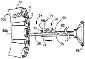
改良型固定ネジドライバーが提供される。ドライバーは、骨ネジのヘッドおよび固定要素のヘッドにおける溝とのくさび形締りばめを提供する。骨ネジと固定要素の両方に同じドライバーが使用可能である。ドライバーは、固定要素がドライバーを脱落させ、創傷内で紛失させることがないことを保障するものである。 An improved fixed screw driver is provided. The driver provides a wedge-shaped interference fit with a groove in the head of the bone screw and the head of the fixation element. The same screwdriver can be used for both the bone screw and the fixation element. The driver ensures that the fixation element does not cause the driver to fall out and be lost in the wound.
ドライバーは、ネジの頭部におけるコンプリメンタリー(complimentary)溝への挿入を容易にするための先細にされた末端を有しており、固定要素を係合し、持ち上げるのに用いられる。また、収容ソケットは、同一目的で先細にされ得る。 The driver has a tapered end to facilitate insertion into a complementary groove in the screw head and is used to engage and lift the fixation element. Also, the receiving socket can be tapered for the same purpose.
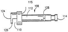
また、骨ネジと固定ネジドライバーの組み合わせが開示されている。ここで、骨ネジおよび固定ネジが骨ネジの挿入前に装着され、これら両方がそれを所定位置から取り除かれることなく一つの器具で締め付けられ得るように、骨ネジドライバーが固定ネジドライバーにおける縦方向の開口部を通過する。 Further, a combination of a bone screw and a fixing screw driver is disclosed. Here, the bone screw driver is installed in the longitudinal direction in the fixation screw driver so that the bone screw and the fixation screw are installed before insertion of the bone screw and both can be tightened with one instrument without removing it from place. Pass through the opening.
また、骨ネジの取付の容易さおよび精度に役立つためのパイロット穴を形成するための器具、およびプレートの取付中に隣接椎骨間に圧縮力を作り出し、取付中にプレートを保持するための器具が提供される。 There is also an instrument for creating pilot holes to help ease and accuracy of bone screw attachment, and an instrument for creating a compressive force between adjacent vertebrae during plate attachment and holding the plate during attachment. Provided.
本発明は、複数の骨ネジが一つの固定要素(ロッキング要素)で適所に固定(ロッキング)されるプレートシステムの好ましい実施態様に関連してまず記述される。これが複合固定プレートシステムと呼ばれる。複合固定プレート(複合ロッキングプレート)が記述され、その後プレートへ骨ネジを固定する固定要素、次に複合固定プレートに関連した骨ネジを、そして最後に複合固定プレートの取付の手段および方法を記述する。その後、単一の固定要素が単一の骨ネジを固定するプレートシステムが記述される。これが単一の固定プレートシステムと呼ばれる。その後、単一の固定プレートに関連した取付の固定要素、骨ネジ、手段および方法が議論される。 The invention will first be described in connection with a preferred embodiment of a plate system in which a plurality of bone screws are locked in place with a single locking element (locking element). This is called a composite fixed plate system. A composite fixation plate (composite locking plate) is described, followed by a fixation element that secures the bone screw to the plate, then the bone screw associated with the composite fixation plate, and finally the means and method of attachment of the composite fixation plate . Thereafter, a plate system is described in which a single fixation element fixes a single bone screw. This is called a single fixed plate system. Thereafter, the mounting fixation elements, bone screws, means and methods associated with a single fixation plate are discussed.
1.複合固定プレートシステム
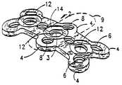
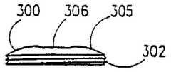
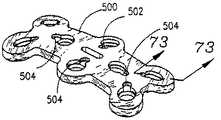
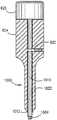
本発明による複合の固定する前頚部の固定プレート2の好ましい実施態様が図1−5に示される(2レベルの固定(隣接した3つの椎骨)に使用される例でここに示される)。プレート2は、一般的に細長い形態を有し、その輪郭はおおむね、ローブあるいは横方向の突出部4が角およびプレート2の側部中心に存在するために、矩形からはかけ離れている。各ローブ4は丸い輪郭をしており、各々円形骨ネジ受け穴6を含んでいる。2つの追加の中間円形の骨ネジ受け穴8が、プレート2の側部内側に位置し、プレート2の縦軸中心線上に中心を有する。ローブ4は、プレート2に、各骨ネジ受け穴6を囲む領域における付加的な強度をもたらす。プレート2のための他の形状が使用されても良いことは認識される。1. Composite Fixation Plate System A preferred embodiment of a composite fixation anterior
中間の対になった骨ネジ受け穴8は、2レベル(3つの椎骨)の固定に使用される。中間骨ネジ受け穴8は、単一レベル(2つの椎骨)固定のために除かれてもよいし、あるいは、追加のレベルが固定されることになる場合には、追加の中間の骨ネジ受け穴8を加えてもよい。 An intermediate pair of bone
プレート2はさらに、3つのロッキング用穴12を備え、その各々は好ましい実施態様において内部にネジ切り3が施されており、その各々が浅いさら穴領域14によって囲まれる。詳細には以下に記載するように、好ましい実施態様では、骨ネジは骨ネジ受け穴に挿入され、各々のロッキング用穴12に関連した単一のあらかじめ取付けられた固定要素が一度に多くの骨ネジ30を適所で固定する。 The
対になった骨ネジ穴の数は、一般的に固定される椎骨の数に一致する。1レベルの固定用のプレートは、単一のロッキング用穴12を有するであろうが、2レベル以上(3つの椎骨)を固定させるためのプレートは、追加の対になった骨ネジ穴に対応する追加の中間のロッキング用穴12を持つことが可能である。図1−6に例示された実施態様において、端部の各固定要素20は、適所に3つの骨ネジ30を固定する。一方、中心固定穴12の固定ネジ21は、適所で2つの骨ネジ30を固定する。図7に示されるように、中心固定要素25は、4つの骨ネジ30を同時に固定するようにも形成され得る。 The number of bone screw holes in pairs generally corresponds to the number of vertebrae that are fixed. A one level fixation plate will have a
特に図3,4および5に示されるように、プレート2は、その底面27(椎体に接する表面)が、縦の平面(その長さに対応する)において、およびその幅に対応する平面横軸において、ともに凹面である、両凹面湾曲を有している。縦の平面における凹面湾曲は、適切な脊柱前弯において整列した椎骨を備えた背骨の前面の適切な形状に一致する。その縦のカーブは、半径方向で15.0cmから30.0cm、より好ましくは20.0−25.0cmの円(ここに「曲率半径」と呼ぶ)の周囲に沿った弧である。図4の端部上に見られるように、プレート2は、半径方向に15−25mm、好ましくは19−21mmの円の曲率半径を有する。プレート2は、2〜3mmの厚さを持っていてもよく、2.25〜2.5mmの厚さが好ましい。 As shown in particular in FIGS. 3, 4 and 5, the
それが関連する椎体に対して同じ高さになるように、プレート2の底面27の輪郭をとることは、プレートの縦軸中心線のみに沿った椎体と接触するより大きな曲率半径を持っている従来のプレートと対照的であり、そのために、椎体に関するプレートの横方向の振動を許容する。本発明のプレートの輪郭は、プレートの縦軸中心線まわりにおける椎体に対するプレート2の振動に対する有効な耐性をもたらし、それにより、プレート2および骨ネジ30に対する応力を減少させ、軟組織がプレートの下に係合されるのを防ぐ。 Contouring the
上記の湾曲によって発生する他の利点は、プレート2が対面する骨表面に、より緊密に適合するということ;プレート2が背骨から突き出る距離がより小さいこと;それが損傷される可能性の有る個所で、軟組織がプレート2の端部の真下での滑りを防ぐこと;そして取付けられた際の側面から見たプレートに垂直な骨ネジ30の角度が、実質的に収斂角で、骨ネジ30間の脊椎の骨を捕えて、よって背骨へのプレートの固定がより強くなることである。 Other advantages generated by the above curvature are that the
図5に示されたように、プレート2の底面27は、好ましくは、多孔質で、粗くされた、または型押表面層を有し、また固定(融合)促進物質(骨のような、形態形成蛋白質)で覆われるか、含浸されるか、含んでいてもよく、こうして、椎骨から椎骨までプレート2の下側に沿った骨の成長を促進する。型押底面27には、さらに、固定促進物質を保持する媒体を備えており、底表面27層が取り付けに先立ってそれをしみ込ませることが可能である。プレート2の底表面27には、粗い吹付け処理あるいは他の従来の技術、例えば、エッチング、プラズマスプレー処理、焼結、あるいはキャスティングなどで、所望の多孔質の型押形態を与えても良い。多孔質の場合、底表面27は、50‐500ミクロン、好ましくは100‐300ミクロンの大きさで孔隙率あるいは孔径を有するように形成される。多孔質の型押底面27が含浸可能な固定促進物質は、骨の形態形成蛋白質、ハイドロキシアパタイトあるいはハイドロキシアパタイトトリカルシウムリン酸塩を含むが、それに限定されない。プレート2は、少なくとも部分的に吸収性材料を含んでいてもよく、それはさらに骨成長(成長)材料で含浸されることが可能で、そうしてプレート2が患者の身体によって吸収され、骨成長材料を放出し、その結果、定期放出性機構として役割を果たす。プレート2は吸収可能な骨成長材料を含有する材料から作られるために、次第にプレートは負荷に対し、より耐性が減少することになり、よって背骨の遅い応力保護を回避して、より自然な方法で椎骨が固定される。 As shown in FIG. 5, the
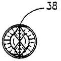
図4および5にさらに示されたように、プレート2の少なくとも一端は凹所18を有し、圧縮装置と協働することが可能である。後に図36と38を参照して詳細に説明する。
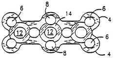
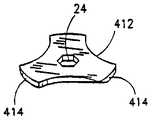
図6は、図1のプレート2の平面図で、固定受け穴に挿入された固定要素20、21を備える。好ましい実施態様では、固定要素20、21は、ネジの形状で、固定穴12のネジ付き内部3と協働する。固定要素20、21の各々は、その初期の開いた方向で示されており、ここで、各固定要素20、21の頭部23の中の切り欠き22の方向は、固定要素20、21の頭部23によって妨げることなく、骨ネジ30が隣接する骨ネジ受け穴6、8に進入することを可能とするように構成されている。頭部23により妨害されることなく骨ネジが隣接する骨ネジ受け穴へ挿入することが可能とするような構成であれば、頭部23を他の配置とすることも可能である事を理解されたい。As further shown in FIGS. 4 and 5, at least one end of the
FIG. 6 is a plan view of the
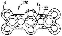
図8は、図1−5のプレート2の別の実施態様の平面図であり、一般にプレート120として参照する。プレート120は、中心の固定穴12に重ね合わされる、縦軸に沿った縦に伸びる長方形の溝122を備える。長方形の溝122は、以下に説明するように、圧縮工程の間に圧縮ツールに結合するプレート120と圧縮ポスト54の間の付加的な相対的な移動を可能とする。 FIG. 8 is a plan view of another embodiment of
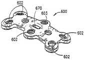
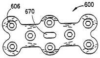
図14および15を参照すると、参照符号70で参照される複合固定プレートの他の実施態様が示されている。ネジ付き固定穴12ではなくむしろ、プレート70において、図17−20に示されるタイプの着脱可能なリベット202を収容するための中心開口部200が提供される。図15は、図14に示されるプレート70の底面図である。プレート70の輪郭は、図1−5に示されるプレート2のそれと同じものである。リベット202は、着脱可能で、上記した固定穴12、溝122と同等の、ネジ無し開口部200の中で嵌合される。他の実施態様では、図14、15の端部固定穴19において使われるように、着脱可能な構成ではなく、プレート70の一部として製造されるリベットを使用してもよい。 Referring to FIGS. 14 and 15, another embodiment of a composite fixation plate referenced by
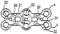
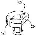
図22に記載のように、複合固定プレートのもう一つの別の実施態様が示され、参照符号230で一般に参照される。プレート230は、固定要素のための、例えば図9および23に示されるキャップ300のような、ネジ付きキャップ、あるいは、例えば、図10-11の固定要素のような平面図の外観を有する切り欠きをそなえたものを用いる。中心の固定穴602は増加する圧縮能力を提供するための細長い溝234を有し、これは更に本明細書で議論される。 As described in FIG. 22, another alternative embodiment of a composite fixation plate is shown and is generally referenced by
図10−13に記載のように、プレート2とともに用いる本発明の固定ネジの形態における固定要素20、21、25の第1の実施態様が示されている。図10は、図7に示される中心の固定要素25の頭部23を例示する上面図である。 As shown in FIGS. 10-13, a first embodiment of the fixing
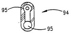
固定要素25のシャフト46はネジ切りされ、プレート2に関連する固定穴12内で、ネジ切り3とかみ合うこととなる。図21に示すように、固定要素21の切り欠き22の各側面上の各区分49は、固定要素頭部23の低面に形成される座面48を有する。図16に示すように、固定要素頭部23は、固定要素頭部23に、可撓性を与えるための2つの溝42を備えていてもよく、この溝42は、固定要素が回転するときに、軸受として作用している間、骨ネジ頭部32の頂部にわたして固定要素を配置させることの助けとなる。あるいは、座面がカムにされる、傾斜づけられる、あるいはくさび形とされることも出来ることは理解されよう。カムにされる、傾斜づけられる、あるいはくさび形とされる特徴は、また、ここで記載される他の固定要素について使うこともできる。 The
図6、10−13に記載のように、固定要素20、21が図6の図に関して時計回りの方向において回転させられるときに、それぞれの座面48はそれぞれの骨ネジ頭部32の曲面表面39上に乗り、適所に関連する骨ネジ30と固定要素20、21を確実に固定することは理解されよう。 As shown in FIGS. 6 and 10-13, when the
あるいは、図21に示すように座面44の代わりに、斜面またはくさび形状とされた表面44が、骨ネジ頭部32に加えられる力を増やすために用いてもよい。固定するときに、固定要素の傾斜がつけられた部分の先端は、骨ネジ頭部32の突出より低いために、固定要素を締めて固定する際に必要な力よりも、固定要素をゆるめて未締結にする際により大きな力が必要となる。しかし、固定要素頭部23は、溝を有する必要はないか、カム化される必要はないか、または適所に骨ネジ30の固定を成し遂げるために傾斜をつけられた表面を有する必要はない。圧力、摩擦力、干渉による嵌合または固定要素がその固定する位置から動くのを防ぐことができる他の係合手段を、使用してもよい。 Alternatively, instead of the
図17−20に示されるリベット202は、図14,15に示されるプレート70に関連して、使用されるものであり、図19および20の断面図で詳細に示される。リベット202は、頭部204、シャフト206およびプレート70の対応する開口部200の中で嵌合するための細長い底区分208を有する。リベット202の頭部204の下面210は、骨ネジ頭部32の表面39を係合するために、固定要素20、21の低面上にカム化されていてもよい不規則な表面を有する。端部固定穴19ために、細長い底区分208の上側表面は、図15に示すように、骨ネジ頭部32に対して、固定位置のリベット202を保持するために、プレート70の底の不規則な表面と協働する不規則な表面を有してもよい。 The
図18のリベットがプレートからの別々の、着脱可能な構成要素であるが、プレートの製造プロセスの間は、プレートの一部として、リベットおよび特に端部固定穴としてのそれらは形成されていても良く、また、リベットは着脱可能ではない構成としてもよい。 The rivets in FIG. 18 are separate, removable components from the plate, but during the plate manufacturing process, rivets and especially those as end fixing holes may be formed as part of the plate. Also, the rivet may not be detachable.
上記の実施態様の各々が、骨ネジ30、そして、関連したプレートに対して、固定要素のしっかりとした装着をもたらす。
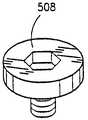
図22に示される複合固定プレート230の別の実施態様において、固定要素が、図23に示されるネジ付き固定キャップ300の形状であってもよい。ネジ付き固定キャップ300は、図22に示されるプレート230の上部内の固定要素用の窪み304の内周上のネジ山303に一致する外周上に、ネジ山302を有する。固定キャップ300は、特にその幅と比較すると、相対的に薄い。固定キャップ300の上部305は、同じように構成された駆動ツールを収容するための非円形貫通孔306を備えている。Each of the above embodiments provides a secure attachment of the fixation element to the
In another embodiment of the
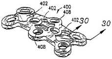
図28、29および30に記載のように、参照符号400によって一般に参照される複合固定プレートのもう一つの実施態様および薄い固定要素412の形状の固定要素が示される。プレート400は、薄い固定要素412の挿入のためのその表面の開口部と、骨ネジ受け穴408の各々と関連する凹部402と、骨ネジ受け穴408の側壁にある溝410を有し、一連の薄い突起あるいは刃414を有し、溝410よりも薄い、固定要素412にプロペラのそれと同様の外観を与える。薄い固定要素412は、骨ネジ穴を覆わないようにプレート内で回転可能とされ、これにより、薄い固定要素412は、骨ネジの取付け前に、外科医によってあらかじめ取付けることが可能となる。薄い固定要素412の限られた回転によって、刃414が溝410に突き出て、関連する骨ネジ30の上部の一部を覆うことができる。薄い固定要素412の刃414は、可撓性を有し、回転するときに、適所に骨ネジ30を固定させるために骨ネジ頭部32の表面39全面にわたり摺動する。論議される他の実施態様と同様に、固定要素の実施態様の各々は、複数の骨ネジ30を固定することができる。多様な複合固定プレートおよび固定要素組合せがすぐに4本ほどの骨ネジを固定することができるが、プレートにそれ自体を固定しているのであれば、より小さい数また何もなくとも、固定するには等しく効果的であることは理解されよう。 As shown in FIGS. 28, 29 and 30, another embodiment of a composite fixation plate generally referenced by reference numeral 400 and a fixation element in the form of a
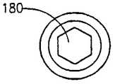
各々の上記した固定要素実施態様の1つの特徴がドライバ係合手段、例えばこれらの場合において、同じツールが骨ネジ30および固定要素を回すために用いることが出来るように、骨ネジ30内の凹部34と同じ大きさの凹部24を有することに注意されたい。また、固定要素は、十分に強くて、破損なしで固定されることに耐えることが可能であるよう充分な質量を有する。 One feature of each of the fixation element embodiments described above is a driver engagement means, for example, in these cases, a recess in the
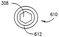
たくさんの切り欠き部分を有する複合固定要素の示された例の全ては、骨ネジ頭部のそれより大きい半径を有する弧を有する。それに加えて、各固定要素20、21の頭部23は、例えば該当する操作ツール、例えば図40−42に示すようなものによって嵌合可能であるような、図9に示す非円形凹部24をその中心にそなえる。図9に示される頭部23の実施態様において、関連するツールは六角頭部を有するが、図80および81に関して論議されるように、頭部23内の凹部の他の形状が使用されてもよい。各固定穴12および固定要素20、21のネジ山は、近い許容度を有し、それでそれらは、骨ネジ受け穴6、8に、骨ネジ30を締めしろがなくても挿入し得るように、それらの方向を確実に保持する。 All of the illustrated examples of composite fixation elements having a number of notches have an arc with a radius greater than that of the bone screw head. In addition, the
固定要素の多様な形式が開示されると共に、教示を考慮して、他の等価な手段が適所に骨ネジ30を固定するために使われてもよいということが理解されよう。図83において、代替の複合固定プレート990が示され、それは骨ネジ30を適所に固定するための、追加の中間骨ネジ受け穴980と関連する固定要素960を有している。プレート990で、より近い間隔および椎骨の数より多くの骨ネジ穴の対が係合することが可能となる。 It will be appreciated that various forms of fixation elements are disclosed, and in view of the teaching, other equivalent means may be used to fix the
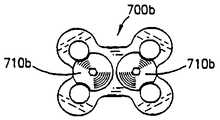
図84A−84Eにおいて、単一レベルの固定のために使用される多様なプレート700a−gが示される。各々のこれらのプレート700a−gは、1つの椎間腔および2つの隣接の椎骨(骨移植片を含む)から成っている1つの脊骨の区分にわたり、また2つの隣接の椎骨に連係される骨ネジ受け穴6を経て椎骨の端部に骨ネジが挿入されるように設計され、適所に固定される。図84A−84Eに示すように、1つの固定要素710または2つの固定要素は、適所に4本の骨ネジを固定するのに使用しうる。図84A−84Eには、回転して骨ネジを固定する前の、各々のプレート700a−eが、それらの開いた方向における固定要素と供に示されている。 In FIGS. 84A-84E, various plates 700a-g used for single level fixation are shown. Each of these plates 700a-g spans one vertebral segment consisting of one intervertebral space and two adjacent vertebrae (including bone grafts) and is linked to two adjacent vertebrae. The bone screw is designed to be inserted into the end of the vertebra through the bone
各々の上記したプレートは、脊柱の前面に一致するように、上記のように、概ね同じような両凹面の輪郭を有してもよい。
図24Aおよび24Bは、本発明の骨ネジ30の1つの実施態様の側面図を提供する。図27は、骨ネジ30の平面図である。各固定要素20、21の凹部24として、同じ形態を有してもよい形状とされた凹部34が、骨ネジ頭部32の中心にあり、この場合には、固定要素20、21を回転するのに使用した同一のツールで回転されてもよい。骨ネジ30のドライバ係合部分は、溝を彫られていても良く、それは雄型あるいは雌型でありうる(示されるように)ことは理解されよう。Each of the aforementioned plates may have a generally similar biconcave profile, as described above, to coincide with the anterior surface of the spinal column.
24A and 24B provide a side view of one embodiment of the
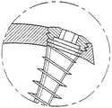
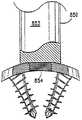
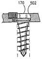
図24Aおよび24Bに示される骨ネジ30の実施態様において、骨ネジ頭部32には段部がつけられており、ネジ軸部33に隣接し、骨ネジ頭部32の上部より小さい直径を有する第一の下頭部35を有する。骨ネジ30のこの実施態様が採用される場合、プレート2の骨ネジ受け穴6、8の各々は、骨ネジ頭部32の上部の直径に合い、締まりばめの寸法を有するさら穴を設けられた領域14を有する。骨ネジ頭部32の低部35は、骨ネジ受け穴6、8のその関連する部分で締まりばめを形成するために必要な大きさにされる。骨ネジ頭部32のより大きな直径の上部は、骨ネジ30が完全にプレート2の骨ネジ受け穴6、8をとおり進行しないことを保障している。骨ネジ30は、完全にどんな形であれ上面を係合することのなくプレート2の上面を通り抜ける。 In the embodiment of the
図44に示すように、ネジ30の頭部32は、大きくされたネジ頭部32の下面が、中間物質でまたはプレートの中間物質の下で狭くなる骨ネジ収容部分の上面を係合するまで、プレートの上面を経て、障害なく、通過する。これが、挿入パスを反転するそれを除いた全ての力に対して、固定されていない場合でも、プレートに対するネジの最大の安定性をもたらす最適化であると考えられる一方、骨ネジ頭部23の下側に最も大きいプレート強度をももたらす。すなわち、プレートは概ね2−3mmの厚さであるだけなので、もし頭部が同じように形成されかつその間の許容度(干渉)がほとんどない場合に、垂直な円周壁は、最もネジの運動を制限することが可能となる。プレートの中心の厚みの近くに頭部のサポートを置くことは頭部が大きいまま維持されてるように、これらを弱めること無くドライバのための凹部を適応させることができるため好ましい。一方で、プレートの上面から離れて頭部の支持部を置くことは、ネジ頭部をプレート内部に深く挿入することができる。およそプレートの厚みの中心に頭部の支持部を置くことは、支える頭部の下に多量のプレート材料が確保され、その一方で、接触点の上下に適切な頭部の長さを提供して、接触点が不必要な運動を防ぐために適切なレバーアームを提供することによって支点として作用することを妨げる事になる。 As shown in FIG. 44, the
図25に示されるように、骨ネジ30'の他の実施態様において、骨ネジ頭部32'は、その上部からネジ先端36'にむかって先細りとされている。またその一方で、骨ネジ頭部32'は、骨ネジ30'が完全に取付けられたときに、関連する骨ネジ受け穴6,8で締まりばめが行われるように寸法が定められている。骨ネジ30'のこの実施態様が使用されるときに、骨ネジ受け穴6、8はさら穴をあけられた領域4を備えている必要はない。 As shown in FIG. 25, in another embodiment of the bone screw 30 ', the bone screw head 32' tapers from its top to the
骨ネジの上記における各実施態様において、骨ネジ30および30'は、先細りとされたネジシャフト33および螺旋形のネジ山31の固有の組合せを提示する。ネジシャフト33の直径は、ネジ先端36の近くのシャフトの末端部から、ネジ頭部32の近くのシャフトの基部に近い部分に向かって、概ね増加する。好適な実施態様において、直径の増加率は、骨ネジ頭部32の近くでもより大きい。この種の形状は応力原因を避け、ネジ-プレート接合における、最も必要とされる箇所に、向上した強度を提供する。ネジシャフト33を先細りにするには、図24Aで示すように、凹形形状を有するようにしてもよいし、または直線状であってもよい。ネジシャフト33の末端部は、一定の直径を採っても良い。 In each of the above embodiments of the bone screw, the bone screws 30 and 30 ′ present a unique combination of a tapered
またその一方で図24Aおよび24Bに記載のように、骨ネジ30のネジ山31は、骨ネジ頭部32の下のシャフトの基部に近い部分から、骨ネジ先端36の近くのシャフトの末端部へ、実質的に一定の外側の、あるいは頂上の直径「d」を有する。ネジ先端36において、ネジ山31の頂上直径は、好ましくは骨ネジ30の骨への挿入および貫通を容易にするよう、1から2回転分、減少させてもよい。 On the other hand, as shown in FIGS. 24A and 24B, the
好適な実施態様において、各骨ネジ30のネジ山31は、わずかに骨ネジ頭部32の最も低い部分35の直径より小さい外径を有し、それは関連するネジ山31の末端、または上端部に隣接している。それに加えて、ネジ山31は、ネジの縦軸方向に、比較的薄くて、外側に向かって先細りになり、三角形の横断面を有する。 In a preferred embodiment, the
椎骨への挿入のための人間の前頚部脊骨の外科用の骨ネジの寸法の例は、以下の通りである:該ネジのネジ部は、およそ10mmからおよそ22mmの長さ(好ましくは12−18mm)およびおよそ1mmからおよそ3mmの頭部長さ(好ましくは2−2.5mm)を有する。ネジ部は、およそ3.6mmからおよそ5.2mmの最大外径(好ましくは3.8−4.5mm)を有すべきであり、また、頭部は、およそ3.8mmからおよそ6mmの直径(好ましくは4−5.5mm)を有する。ネジ山ピッチは、およそ1.25mmからおよそ2.5mm(好ましくは1.5−2.0mm)であり、鋭く薄いネジ切りされた側面を有する。ネジ山の2つの表面の頂点はおよそ21度未満(好ましくは15度)の角度を有し、ネジ山の基部は厚さおよそ0.60mm(好ましくは0.25mm−0.35mm)未満である。ネジは、軸部の端部の上方近傍から、縦軸に沿って、ネジ頭部部分の下方近傍へ向かって増加する谷径を有する。好ましくは、ネジ端部の先端は、少なくとも一つの切り欠きセクションによって溝が彫られ、これによってネジをセルフタップとする。 Examples of dimensions of a surgical bone screw for human anterior cervical spine for insertion into the vertebra are as follows: the threaded portion of the screw is approximately 10 mm to approximately 22 mm long (preferably 12 mm). −18 mm) and a head length of approximately 1 mm to approximately 3 mm (preferably 2-2.5 mm). The threaded portion should have a maximum outer diameter of approximately 3.6 mm to approximately 5.2 mm (preferably 3.8-4.5 mm) and the head is approximately 3.8 mm to approximately 6 mm in diameter. (Preferably 4-5.5 mm). The thread pitch is approximately 1.25 mm to approximately 2.5 mm (preferably 1.5-2.0 mm) and has sharp and thin threaded sides. The apex of the two surfaces of the thread has an angle of less than approximately 21 degrees (preferably 15 degrees) and the base of the thread is less than approximately 0.60 mm (preferably 0.25 mm-0.35 mm) thick. . The screw has a valley diameter that increases from near the upper end of the shaft portion toward the lower vicinity of the screw head portion along the vertical axis. Preferably, the tip of the screw end is grooved by at least one notch section, thereby making the screw self-tapping.
たとえ骨ネジ30のネジ山31が薄い側面を有するとしても、それにもかかわらず、ネジ山は骨より強く、このネジ山が効率的に薄い螺旋形の溝を骨組織に切り込むように、そこに挿入される。ネジ山の厚みによって移動する骨の量はネジ山の薄い形状によって最小にされるが、ネジ山の実質的な頂上直径は骨と接触するネジ山の表面領域を最大にする。骨ネジ頭部32の近くのネジシャフト33の直径を大きくすることはそこに必要とされる強度を増す。一方、この種の強さが必要でない場合、骨ネジ頭部32から離れたネジシャフト33の直径を減少させることは、骨に対してネジ山31を係合させる最大領域を確保することが可能となる。 Even though the
好ましい実施態様において、図24Aおよび26に示すように、骨ネジ先端36は、骨ネジ30がセルフタップを行えるように、縦溝38が切られている。セルフタップを行うことができない、従来技術の前頚椎の外科に使用される従来技術骨ネジと異なり、本発明のネジのネジ山形態は、ネジ山が非常に鋭く、溝が形成されている点で、従来のネジよりも、よりタップに近い形状である。骨ネジ30の追加の実施態様は、図53−55に示される。 In a preferred embodiment, as shown in FIGS. 24A and 26, the
一例として、3本の隣接の脊椎骨(2つの合間または2つの脊骨の区分)を固定するためのプレートを示す。椎骨と関連がある骨ネジ受け穴の各一組が、プレートの区分であるとみなされ、例えば、図1における3つの区分、上部、中間部、下部区分として示される。これまでの説明は、2つの間隙をはさむ3つの椎骨の接合に使用されるプレートに関するものであったが、接合する椎骨の数に対応して適切な数及び位置の骨ネジ受け穴を備えたより長い又は短いプレートを形成し得る。例えば図1の線9に沿った区分または図82−84Fに示すプレートの中間の区分(セグメント)のような、より少いあるいは多い中間のセグメントとして示されるプレートという形をとり得ることを理解されなければならない。 As an example, a plate for fixing three adjacent vertebrae (two gaps or sections of two vertebrae) is shown. Each set of bone screw receiving holes associated with a vertebra is considered to be a section of the plate and is shown, for example, as three sections in FIG. 1, upper, middle, and lower sections. The description so far has been concerned with plates used to join three vertebrae with two gaps between them, but with a suitable number and position of bone screw receiving holes corresponding to the number of vertebrae to be joined. Long or short plates can be formed. It will be understood that it may take the form of a plate shown as fewer or more intermediate segments, such as, for example, the section along line 9 of FIG. 1 or the middle section of the plate shown in FIGS. 82-84F. There must be.
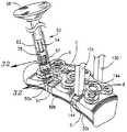
図31−42を参照し、本発明のプレートを取り付ける方法のステップの概要は、以下に説明する。本発明のプレートを取り付けるための手段および方法の詳細な説明は、概要に続く。 With reference to FIGS. 31-42, an overview of the steps of the method of attaching a plate of the present invention is described below. A detailed description of the means and methods for attaching the plates of the present invention follows the overview.
ステップ1
椎体間固定を完了し、外科医は、固定すべき領域の脊柱の前面に沿って、あらゆる骨スプールあるいは局所的な不整を取り除く。
Having completed the interbody fusion, the surgeon removes any bone spools or local irregularities along the anterior surface of the spine in the area to be fixed.
ステップ2
外科医によって測径器、定規、テンプレート、などによって脊柱上の距離を測定することによって正しい長さのプレートが選ばれる。そのプレートは、固定される脊柱の距離を測って、固定される各々の端部の椎骨のそれぞれの部分を部分的に覆うのに十分な長さを有する。
The correct length plate is selected by the surgeon measuring the distance on the spinal column with a caliper, ruler, template, etc. The plate is long enough to measure the distance of the fixed spine and partially cover the respective portion of each fixed vertebra.
ステップ3
プレートホルダーを利用して、プレートは傷害部位に置かれて、固定される脊柱の部分と関係がある位置、長さ、そして、ネジ穴配列を確かめるために配置される。
Utilizing a plate holder, the plate is placed at the injury site and placed to ascertain the position, length, and screw hole arrangement associated with the portion of the spinal column to be secured.
ステップ4
図31に示すように、このように、配置されて、しっかりと保持されるプレートについては、プレートは固定される(例示のみであるが、主要な脊椎骨として示す)いずれの椎骨に付けられてもよい。
As shown in FIG. 31, for a plate that is placed and securely held in this way, the plate can be fixed (attached only as an example but shown as the main vertebra) and attached to any vertebra Good.
サブステップ4A
パイロット(ガイド)穴パンチ60は図32に示された通りフルート2に付けられる。または、この代わりに、好ましいわけではないが、図37に示された通り、ドリルガイドが使われてもよい。いずれにしても、確実にパイロット穴形成手段は、位置が調整され、そして、プレート骨ネジ受け穴壁によって捕らえられる。Substep 4A
The pilot (guide)
サブステップ4B
パイロット穴は、それから図32のパイロット穴パンチで突くことまたは図37のドリルで穿設することによって形成される。好ましいわけではないが、選択肢として、パイロット穴の形成は全体で処理されてもよく、そのパスに沿った後部脊椎皮質への距離より短い長さを有するように選ばれた正しいネジが、直接挿入されてもよい。Substep 4B
The pilot holes are then formed by piercing with the pilot hole punch of FIG. 32 or drilling with the drill of FIG. Although not preferred, the formation of the pilot hole may be processed as a whole, and the correct screw chosen to have a length shorter than the distance to the posterior spinal cortex along that path is directly inserted. May be.
該当するネジ長さの判定は、X線写真、MRIのものまたはCTスキャンから測定するかまたはテンプレート化することによってなされるか、または椎間腔の深さを測定することによって直接決定される。 Appropriate screw length determination is made by measuring or templating from radiographs, MRI or CT scans, or directly by measuring the depth of the intervertebral space.
ステップ5
適切に選択されたネジは、ネジドライバ係合手段の具体的な形状にかかわらず、ネジドライバに取り付けられる。また、ネジは、挿入サイトへの挿入の間、しっかりとドライバに固定されるように締まりばめを有するように設計されている。図41、42、63、64、80および81は、ドライバおよびネジのこの種の嵌合を成し遂げる多様な方法を示す。ネジおよびドライバ界面におけるウェッジングに加え、クリップ、ばね、および他の手段が図80に示されているように、一時的かつ反転可能にドライバにネジを固定することは知られている。ここで、溝を彫られた内側にはねているスリーブは、そのままでプレートにネジ込まれて、自動的にネジキャップをリシースして押し戻されるまで、ネジキャップを保持する。
A properly selected screw is attached to the screw driver, regardless of the specific shape of the screw driver engagement means. The screw is also designed to have an interference fit so that it can be securely fastened to the driver during insertion at the insertion site. 41, 42, 63, 64, 80 and 81 show various ways of accomplishing this type of engagement of the driver and screw. In addition to wedged at the screw and driver interface, clips, springs, and other means are known to temporarily and reversibly secure the screw to the driver, as shown in FIG. Here, the grooved inwardly sleeved sleeve is screwed into the plate as it is and holds the screw cap until it is automatically pushed back by resealing the screw cap.
いったん、第1の骨ネジがプレートを通して脊椎骨に完全に挿入されると、図33に示されすでに記載されている方法における横の組のもう一方を挿入することが、好ましい。
同様の方法で、外科医の選択によって、固定された椎骨内に含まれる各椎骨であって、固定構造物のちようど端部椎骨に残りの骨ネジが挿入することが可能であり、または付加的に、ネジを固定移植片に挿入することが可能である。Once the first bone screw is fully inserted through the plate and into the vertebra, it is preferable to insert the other of the side set in the manner shown and described in FIG.
In a similar manner, depending on the surgeon's choice, each vertebra contained within the fixed vertebra can be inserted with the remaining bone screw into the end vertebra just beyond the fixed structure, or additional In addition, a screw can be inserted into the fixed implant.
しかし、図33、34、38および39に示すように、本発明では、外科医のオプションで、固定構造物の一部分または全てを圧力を加えながら配置し、そして、マルチセグメントされる場合には、区分間において又は固定構造物の全体に渡ってそうすることが可能である。 However, as shown in FIGS. 33, 34, 38 and 39, the present invention provides a surgeon option to place some or all of the fixation structure under pressure and, if multi-segmented, segment It is possible to do so between or throughout the stationary structure.
同じ手順は、本発明のプレートシステムのいずれにおいても、おおむね使用して良いことが理解されよう。
図31に示すように、固定骨移植片構造物を形成している隣接の椎骨50間の脊骨の椎間腔において、あらかじめ取り付けられた固定移植ブロック51によって、椎骨50a−cは、お互いから分離される。プレート2は、図を単純化するために取り除かれる要素20、21を固定ことに関する図31に示される。好ましい実施態様において、固定要素20、21は、椎骨50の椎体にプレート2を配置する前に、図6に示される位置にあらかじめ取付けられても良い、および好ましくはそうされ、このことにより外科時間および問題を除く。It will be appreciated that the same procedure can generally be used in any of the plate systems of the present invention.
As shown in FIG. 31, in the intervertebral space of the vertebrae between adjacent vertebrae 50 forming a fixed bone graft structure, the
プレート2は、いかなる公知のプレート保持手段により、しかし好ましくは、図39に示される脊椎圧縮ツール100の圧縮アーム104,130の側面についた切込み142によって図45,46あるいは70に示された保持ツールによって、または更なる選択肢として、図70の設計に同様の単一のプレートホルダーによって、適所に保持されてもよい。 The
図45に示すように、プレート2のネジ付き固定穴12のうちの1つを係合するための1つの端部におけるネジ山878を有する中心ロッド874を備えた、中空管状ハウジング872をプレートホルダー870が有する。ハウジング872の底端部は、ハウジング872が回転するのを防ぐプレート2の骨ネジ受け穴に嵌合するように、外側ならびにそれから下方へ伸びる突起880,882を有する。中心ロッド874は、その上端部で中心ロッド874に固定するハンドル(図示せず)を回転させることによって回転しうるように、ハウジング872に位置する。 As shown in FIG. 45, a hollow
図46において、プレートホルダー890の別の実施態様が示される。単一の固体部材890は、プレートの中心のネジ付き固定穴12に取付けるためのその底端部において、ネジ付き突起894を有する。この実施態様のホルダー890の底面は、くぼみ14として示される、固定穴12に隣接するプレートの表面の輪郭にマッチするように輪郭付けられる。 In FIG. 46, another embodiment of a
図67−68に記載のように、椎骨に配置されている一方、プレートのいずれかを保持するプレートホルダーの実施態様が、一般に参照符号800によって示されている。プレートホルダー800は、プレート600のネジ付き固定穴12のうちの1つに係合するための、一端にハンドル806を、他端にネジ山808を有する中心ロッド804を備える、中空管状ハウジング802を有する。ハウジング802の底端部は、ハウジング802が回転することを防ぐ、端部と中間のローブの間のプレート2の側端にそって嵌合するよう、外側およびそれから下方814,816に伸びる突起810、812を有する。それがその上端部で中心ロッド804に固定されるハンドル806を回転させることによって回転することが可能なように、中心ロッド804はハウジング802に位置する。この中心ロッド804は、数多くの従来の方法によって、例えばおよそ3−5mmの長さを有する環状のくぼみおよび中心ロッド804を係合するハウジングから内側に突出するセットネジを有する中心ロッド804を有することによって、幾分か上下動可能となるように、ハウジング802に取付けられてもよい。一旦、プレート600が適当な場所にあり、かつ、プレートが骨ネジ30により椎骨のうちの1つに取付けられると、中心ロッド804はプレート600にある開口部から切り離され、ホルダー800は取り除かれる。 As shown in FIGS. 67-68, an embodiment of a plate holder that is positioned on a vertebra while holding any of the plates is indicated generally by the
図69Aは、プレートホルダー850の別の実施態様である。単一の固体部材852は、その底端部に、プレート12の中心のネジ付き固定穴12への取付けのためのネジ付き突起854を有する。固体部材852は、また、骨ネジ受け穴6に、ネジ切りされてもよい。この実施態様のホルダー850の底面は、くぼみ14として示される、固定穴12に隣接するプレートの表面の輪郭に適合するように、輪郭付けられる。 FIG. 69A is another embodiment of the
図69Bは、プレートホルダー850’のもう一つの別の実施態様である。骨ネジ受け穴6を係合するために形成される端部853'を有するハウジング851’は、不均等な直径とネジ部分857’を有しているロッド855'を含む。 FIG. 69B is another alternative embodiment of the plate holder 850 '. The housing 851 ′ having an
ロッド855’は、図68に示されるハンドル806と同様のハンドルによって回転させられるので、ロッド855’は、ハウジング851’内へ下方に動して、適合するネジ山858’に入る。ロッド855’端部が下方に駆動されるので、プレートの骨ネジ収容保持へプレートホルダー850をくさびでとめている部分859a’および859b’(図示されていない859c’859d’)を拡張する。プレートホルダー850’は、ネジが取付けられていない骨ネジ受け穴に最もよく使われるが、全ての種類の骨ネジ受け穴に対して有効に働く。 Since rod 855 'is rotated by a handle similar to handle 806 shown in FIG. 68, rod 855' moves down into housing 851 'and enters a matching thread 858'. As the end of the rod 855 'is driven downward, the portions 859a' and 859b '(859c'859d' not shown) that wedge the
図70に記載のように、参照符号800’で参照されるプレートホルダーの別の実施態様が示されている。ここでは、外科的処置によるプレートホルダー800の締めしろを減らしている取付け処置の間に、最初に、シャフト804を回転させることによる、プレートにプレートホルダー800を取付けるため、そしてそれから、延長部864により、側面に対して離れてプレートホルダー800’を保持するために使用される着脱可能なハンドル860がある。 As shown in FIG. 70, another embodiment of a plate holder referenced by reference numeral 800 'is shown. Here, during an attachment procedure that reduces the interference of the
図38に記載の圧縮ツール100は、その自由端に固定される第1の圧縮アーム104を有する歯車バー102を備えて示される。圧縮アーム104は、くぼみに係合させるため一端にフック110を有する図36に示されるプレート係合要素108またはプレート2の端部内の切込み18を取り外し可能に保持するための、または、図33-34に示す圧縮ポスト54を取り外し可能に保持するための穴106をその末端に有する。図36に示すように、プレート係合要素108は圧縮アーム104の対応する穴106に挿入されるシャフト112とそして、穴106に正確にプレート係合要素108の挿入の深さを制限するための、穴106の底面に載るフランジ115を含む。穴106内のプレート係合要素108を保持するために、好ましくは金属の、リングばね128が、シャフト112の環状のくぼみに位置する。 The
図38-39に記載の、圧縮ツール100は、歯付きバー102に沿って第1の圧縮アーム104と平行して移動できる第2の可動圧縮アーム130を含む。
第2の圧縮アーム130の末端部にも、着脱可能なポスト134を収容できる穴106と同じ穴132を有する。これら穴106および132は同じものとされ、これにより、どちらの圧縮アーム104、130でも、着脱可能なポスト134を保持するために使用可能とされ、また、圧縮ツール100がいかなる方向においても使用可能とされている。フルートに対して角度があるときでさえも操作可能とするプレート係合フック110を備え、プレート係合要素108および圧縮ポスト54が2本の圧縮アーム104,130の穴106、132において回転しスライドすることができることによって、圧縮ポスト54およびプレートを介して、装置を脊柱に、容易に取付け可能とさせる。The
The distal end of the
圧縮アーム130は、歯付きホイール(見えない)から成っている駆動アセンブリを有し、歯付きホイールは、バー歯車102の歯ギア138に係合されて、圧縮アーム130が歯車バー102に沿ってハンドル140の回転によって移動できるように圧縮アーム130に接続しており、ハンドルは、歯付きホイールに係合されている。ハンドル140が図38に示される矢印の方向に回されるときに、圧縮アーム130は圧縮アーム104の方へ移動する。駆動アセンブリは、自己固定リリースメカニズムを有し、それによってリリースの起動なしで、お互いから離れる2本の圧縮アーム104、130の動きを防ぐ。各圧縮アームの内側の末端上の対向する側面上には、図37に示すように、中心ローブ4および端部ローブ4の間のその側面に沿って、プレート2を保持するための切込み142または凹部がある。 The
歯車バー102および圧縮アーム104、130は、直線状に記述されているが、必要ならば、椎骨内の脊柱前弯を誘発するために、歯車バー102および圧縮アーム104、130がアーク形にまたはそうでなければ形づくられてもよいことは可能である。 The
図31に示すように圧縮ツール100はプレート2を保持するために使われる。その結果、プレート2が適切に配置されるときに、圧縮アーム104、130の端部144は、椎間腔に置かれた固定移植構造物51と同一線上に、位置する。ギャップは、プレート2および各固定移植構造物51との間にあり、アーム104、130の自由端部を収容する空間が設けられる場合には、それらはプレート2の底面を越えて形成される。後述するように、同様の圧縮ツール100を、椎骨50へのプレート2の取付けの間に、配置される骨移植片を有する複数の頸部の椎体を圧縮するために使用してもよい。 As shown in FIG. 31, the
図31を参照すると、プレート2は適切なホルダーによって保持されるが、この場合、ボルダーは、圧縮アーム104および130として示されている。骨ネジ受け穴6が固定される各々のそれぞれの椎骨50a−cに位置合わせを行われるように、該当する長さのプレート2が適切に配置される。次のステップとして、椎骨50aにおいて骨ネジ30自身の取付け前に、骨ネジ受け穴6が形成される。最初に、プレート2を上部の椎骨50aに取付けるように、手順が記載されているが、プレート2はいかなる順序でいずれの椎骨に取り付けてもよい。上記したように、異なるサイズにされたプレートが使用可能とされていることから、医者は、骨ネジ受け穴6、8が3つの隣接する椎骨50a、50bおよび50cに配置されるような適切なサイズのプレートを選ぶ。パイロット穴は、図31および32に示されるパイロット穴形成装置60によって形成される。公知の従来技術およびネジプレーティングシステムによるものと違って、骨ネジ30は、従来のように椎骨に形成されたネジ穴の形成なしで挿入されてもよい。なぜならば、骨ネジ30は好ましくは鋭く尖らされ、タップし(雄ねじ切りされ)、そして、それらの先端において、骨へのネジ挿入および引抜きを補助するために先細とされた外径を有するためである。但し、椎骨の骨への穴がネジ挿入の前に形成されてもよい一方、しかし、穴がネジの谷径より小さい直径であり、そして、従来技術とは異なる目的のためである。従来技術では、ネジがタップではなかったため、穿設される穴は、ネジの谷径(小径)と同じ直径で、しかし好ましくはそれよりも大径でなければならなかった。ここでは、パイロット穴を作り、骨ネジ30のための適当な経路を確保することにより、骨ネジ30の挿入の間に椎骨の損傷を防ぐことが望ましい。さらに、パイロット穴形成装置60は、この挿入に使用されるタップ骨ネジ30の受け入れに要する椎骨質量をよりコンパクトにする。 Referring to FIG. 31, the
図31および32に示すように、パイロット穴形成装置60は、貫通孔63を備えた底を有する中空円筒形ハウジング62を含む。ハウジング62は、ハウジング62の底にある貫通孔63を通って延びる中心シャフト64を含む。シャフト64の先端66は、徐々に鋭い先端65に向かって先細りになる。シャフト64は、ハウジング62内のシャフト64の動きを案内するために密接にハウジング62の内径に対応する直径を有するリング部材73を備えている。圧縮ばね67は、ハウジング62のリング部材73および底の間に配置される。圧縮ばね67は、ハウジング62内に格納された位置に鋭い先端65を普通の状態では推進するバイアス力を提供する。シャフト64の上端は、意味された手動で押し下げられるか衝撃器具によって打たれるように意図されたハウジング62の外側に伸びている拡大頭部68を有し、ハウジング62から、そして、椎体50aに鋭い先端65を駆動する。シャフト64は、ばね67が完全に圧縮された時の長さを考慮して、長さが与えられ、そうして椎体に形成されるパイロット穴の最大深さが決定される。深さはパイロット穴が椎体の後部皮質に届かないことを保障するように選ばれ、椎体の後部皮質は脊柱管に隣接する。 As shown in FIGS. 31 and 32, the pilot
穴形成装置60の一定の構造上の特徴は、より詳細に図32に示される。特に、ハウジング62の底端部は、正確にプレート2の骨ネジ受け穴6または8において嵌合するために必要な寸法にされる突出部分69を有することが理解できる。突出部分69の底71は、ハウジング62の軸に対して垂直な平面において平らである。ハウジング62の突出している部分69が骨ネジ受け穴6、8に、ぴったりと挿入される。そして、平らな底71は、プレート2の上側表面に押しつけられ、シャフト64の先端66がプレート2に係合する部分に対して垂直な軸を有する椎骨のパイロット穴を形成することを保障する。また、これにより、この軸は、プレート2に係合する部分の上下の面と平行である平面に対して垂直に形成されるため、骨ネジ30がその後取り付けられることが保障される。 Certain structural features of the
ネジ付き骨ネジ受け穴を有するプレートが使われるときに、パイロット穴形成装置60の下端は、骨ネジ受け穴6、8内のネジ山に係合するようにネジ切りされ、それによって、プレートおよびパイロット穴形成装置を共に固定し、パイロット穴形成装置とプレート2の間の安定した嵌合を保障する。パイロット穴形成装置の内部壁間に残された小さい空間の中で嵌合しなければならないので、シャフト64の先端66の直径は小さいことに注意されたい。形成されているものは、タッピング骨ネジ30のためのパイロット穴だけであるため、小さい径で十分である。 When a plate having a threaded bone screw receiving hole is used, the lower end of the pilot
図37を参照すれば、いずれにせよ、もしパイロット穴形成装置60の利用によるよりむしろ、穿設することによって椎体50内のパイロット穴を形成することが望まれる場合には、図37で示す下端部を備えて、ドリルガイド80で穴を形成させてもよい。ドリル80のガイドは管状の部材82と、プレート2の関連する骨ネジ受け穴6、8における正確な締まりばめ(干渉)を形成する寸法とされた小径の下端部84とからなる。小径下端部84に沿うように、ドリルガイド80は、ドリルガイド80の縦軸に対して垂直な平面を形成する端部面を具備するので、小径部分84が、骨ネジ受け穴6にはめ込まれ、そして、小径部分84を取り囲んでいる面がプレート2の上面と同一平面を形成するように直接接触するとき、ドリルガイド80のドリルガイド穴86の軸は、正確にプレート2の上下面に対して垂直となる。上記した場合と同様に、ドリルガイド80の底端部はネジ切されていてもよく、そうしてプレート2のネジ付き開口部と螺合する。 Referring to FIG. 37, in any case, if it is desired to form a pilot hole in vertebral body 50 by drilling rather than by using pilot
プレート2の上部の2つの骨ネジ固定穴6を通して、穴形成装置60またはドリルガイド80のいずれかによって、骨ネジ受け穴6,8が椎体50aにおいて形成された後、しっかりとプレート2が圧縮ツール100またはプレートホルダ一800により椎骨50に対して保持された状態で、骨ネジ30は、椎骨50にねじ込まれる。こうして、プレートを椎骨50aに固定する。 Through the two bone
骨ネジ30をプレート2の中心の骨ネジ受け穴を通して隣接の椎骨50bに取り付ける前に、所望により次の隣接の椎骨50b内に固定移植片を圧入することも可能である。最初の骨ネジが椎骨50aの適所にあると、プレートホルダー100または800はプレート2から取り除かれてもよい。2つの隣接の椎骨50aおよび50b間の固定移植構造物の圧入は、次のように実施される。 Prior to attaching the
圧縮ポスト54は、図33、34および35に示される、挿入ツール90によって、プレート2の中心の固定穴12を通り脊椎骨50bの椎骨に打ち込まれ、次のステップにおいて椎骨50aおよび50b間に圧縮力を加えるために使われる。圧縮ポスト54は、その下端に鋭い先端57を具備したシャフト56と、穴の深さを制御する道具の役目を果たす中心から外周方向に広がったカラー58と、その上端部近傍に拡大頭部55を画定する、周辺溝59とからなる。 The
圧縮ポスト挿入ツール90は、圧縮ポスト54を受け入れるためのその下端96で、閉じた中空部分94を具備しているシャフト92と、その他端部の拡大パーカッションキャップ98とからなる。圧縮ポスト挿入ツール90はその下端96において、くぼみ97内に圧縮ポスト54上の拡大頭部55を係合可能とするためのその内壁内に凹部99を具備している第2の開口部95も含んで構成される。図35に示すように、第2の開口部95は、挿入ツール90の中空部分94と連通する。 The compression
図38を参照すれば、圧縮ツール100の第2の圧縮アーム130内の穴132は、それから椎骨50bに挿入された圧縮ポスト54にわたした状態で用いられ、そして、プレート係合要素108は、圧縮ツール100の第1の圧縮アーム104の穴106に挿入される。図36に示されるプレート係合要素108のフック110は、プレート2の終端の切込み18にはめ込まれ、これにより、図38に示すように、脊椎骨50aに挿入された骨ネジ30によって固定される。しかし、上記したように、圧縮ツール100は、回転可能であるため、第1の圧縮アーム104は現在底部に位置しているが、椎骨50c内の圧縮ポスト54にわたって嵌合することが可能である。 Referring to FIG. 38, the
プレートが骨ネジ30によって椎骨50aに取り付けられ、そして、圧縮ポスト64を50b隣接の椎骨50bに固定するので、ハンドル140の回転による椎骨50aの方向の第1および第2の圧縮アーム104および130の動きが、隣接の椎骨50aおよび50b間の骨移植片構造物51圧縮する結果となる。数ミリメートルの距離は、骨移植片構造物51の圧入に充分である。所望の圧入が得られると、上記のように、骨プレート2の骨ネジ受け穴8への骨ネジ30の挿入のための、骨ネジパイロット穴は、椎体50bにおいてパイロット穴形成装置60によって形成され、隣接の椎骨50bにプレート2を固定する。圧縮ツール100は、それからリリースの起動によって取り外されてもよい。 Since the plate is attached to the
図39は、ちょうど記載したように、骨ネジ30を中間椎体50bに取り付けた後に、下部2つの椎体50bおよび50c間の圧縮を誘発するための圧縮ツール100の利用法を例示する。図39に示すように、圧縮ポスト54は、中間椎体50bの適所に残され、追加の圧縮ポスト54は、端部突起4間の凹部において、プレート自体に対して遠部のパイロット穴形成ツール60によって下部椎体50cに打ち込まれ、下部圧縮ポスト64を、図に示すように椎骨50bの方向へ動かすことが可能となる。オリジナルの圧縮ポスト64は、第1の圧縮アーム104内の穴106に挿入され、追加の圧縮ポスト54は、圧縮ツール100の第2の圧縮アーム130の穴132に挿入される。またその一方で、上で示したように、ハンドル140の回転が、お互いへ向かう2本の圧縮アーム104、130の動きとなり、椎骨50b内の上部の圧縮ポスト54の方へ向かって、椎骨50c内の圧縮ポスト54が動くこととなり、椎骨50bおよび50c間の固定移植構造物51をもう一度圧縮する。椎骨50bがプレート2の骨ネジ受け穴8内の骨ネジ30の挿入によって、プレートに固定した時から、椎骨50b内の上部の圧縮ポスト54は動いくことができない。このように、下部圧縮ポスト54および椎骨50cだけは、動いてもよい。上述の通り、椎骨50cに関連するパイロット穴が形成され、そして、骨ネジ30は骨ネジ受け穴6に挿入される。その後圧縮ツール100は、取り除かれる。圧縮ポスト54は、それから圧縮ポスト挿入/除去ツール90の第2の開口部95のそれを挿入することによって椎骨から抜き取られ、図34に示すように、それがくぼみ97によって圧縮ポスト54の端部の拡大頭部55に係合させる。 FIG. 39 illustrates the use of the
圧縮の順序内であれば他の変形例が用いられてもよいと認識される。例えば、椎骨50bおよび50c間の固定移植構造物51の圧縮の間は、圧縮ツール100のフック110はプレート2の端部の切込み18を係合してもよく、そして、圧縮ツール100の他の圧縮アームは第3の隣接の椎骨50c内の圧縮ポスト54を係合してもよい。プレート2が、椎骨内の圧縮ポスト54の挿入のため、プレートの終端に、ローブ間の凹端部切り欠き部分を具備することに注意されたい。 It will be appreciated that other variations may be used within the order of compression. For example, during compression of the
一方、圧縮ポスト54の挿入のために、プレート2の端部の下には空間が形成される必要はない。
上記の手順は椎体50a、50bおよび50cに、完全に挿入される骨ネジ30を用いて実行され、脊柱前弯が骨移植片構造物51の圧縮の間、維持されることに注意されたい。On the other hand, there is no need to form a space under the end of the
Note that the above procedure is performed with
上記したように、プレート2を椎骨50a、50bおよび50cに取り付けるための手順は、プレート2上の適所に固定ネジ20、21を伴わない状態で、例示した。図40は、外科的手順のステージにおける図1−5のプレート2を示している斜視図であり、ここでは、骨ネジ30は、3つの隣接の椎骨50a、50bおよび50cに完全に挿入され、そして、固定ネジ20、21を、およそ90度の角度で回転して、3つの骨ネジ30を適所に固定し;左側に見られる固定ネジ20を、およそ60度の角度で回転して、3つの骨ネジ30を適所に固定し、そして、中心固定ネジ21を、およそ90度の角度で回転し、2つの他の骨ネジ30を適所に固定する。この時で、各固定ネジ20、21のカム化表面44のうちの1つは、頂上にそれぞれの骨ネジ30のネジ頭部32を載せる。 As described above, the procedure for attaching the
固定キャップ300の取付けは、また、固定キャップ300の穴306の深さに一致する長さを有する適切に形づくられた先端222を具備する、例えば図41および42に示されるツール220で行われてもよい。最も末端に近いツール220の端部222は、フレア状にされているので、それが操作の容易さのためにネジキャップ300と摩擦嵌合を形成し、ツール200からネジキャップ300が離れて落ちないようにされている。 Attachment of the
図43は、プレート2の2つの端部固定ネジ穴6の中心の平面における断面図であり、それらの取り付けられた位置における2つの骨ネジ30およびその固定位置における固定要素21を有する。図44は、図43のプレート2における骨ネジ30のうちの1つの拡大図である。好ましい実施態様において、関連する骨ネジ30の縦軸によって横切られる先端で、各ネジ30の軸は、プレート2の上下の面に対する接平面に対して、概して垂直である。このように、図18の平面におけるプレート2の湾曲のために、骨ネジ30はお互いの方へ所望の角度で収斂するように向けられてもよい。図18に示される2つの骨ネジ30の軸は、およそ45度の角度で交差させることができる。あるいは、プレートの左右の湾曲が、ヒト成人頚椎の前面の表面に対して、同じになるようであってもよいし、端部で最適の収斂がなされるように見られるときに、対のネジ穴の軸はプレートに対して垂直からそれることができる。 FIG. 43 is a cross-sectional view in the plane of the center of the two end fixing
一旦挿入された骨ネジ30はプレートに固定されるので、骨ネジ30の各対において強固な三角フレーム構造の「爪」が得られる。この結果、角度のついた骨ネジ間に骨材料のくさび形の質量を封じ込めるのでたとえネジ外れ(thread stripping)があったとしても、椎体50a、50b及び50cは非常に安定してプレートに取り付けられる。「爪」は、三脚構成内の3つの曲げられた骨ネジによってまたは4面爪構成内の4つの骨ネジによって更に形成されてもよい。 Since the
各々の上記の実施態様によるプレーティングシステムは、第1の実施態様に関して例示して記述したように、上記と同様に取り付けられてもよく、同じ器具およびツールを使ってもよい。図22に示される実施態様の場合、圧縮作業は、中心固定ネジ穴12の代わりに溝604によって実行される。 The plating system according to each of the above embodiments may be mounted as described above and may use the same instruments and tools as illustrated and described with respect to the first embodiment. In the embodiment shown in FIG. 22, the compression operation is performed by the groove 604 instead of the center fixing
b.)単一の固定プレートシステム
単一の固定プレートシステムを、ここで記述する。図47-52は、単一の固定プレートシステムの第一の実施態様の図である。プレート600の輪郭は、図1-5に示されるプレート2と同じものである。プレート600は、骨ネジ受け穴602を含み、図56−59に示される固定キャップ610の形状で、対応する固定要素を収容する内部のネジ切り603がなされている。例えば、プレート600において、骨ネジ穴602は、4−6mmの好ましい範囲を有するおよそ5mmの外径と;この使用のための3.5−5.8mmの範囲で、およそ4.8mmのネジ付き内径を有する。ネジ山以外の取付け手段は使用してもよく、例えば、それはバヨネット型取付要素である。b. ) Single fixed plate system A single fixed plate system is described here. FIGS. 47-52 are views of a first embodiment of a single fixed plate system. The outline of the
各骨ネジ受け穴602の底は、図53-55に示すように、関連する骨ネジ170を保持するための適切に選ばれた寸法で内側に段付けされた部分を具備する。以下により詳細に説明するように、本実施態様において、図56-59に示されるネジ山608を具備している固定キャップ610の形の単一の固定要素は、骨ネジ収納穴602の各々に関連する。 The bottom of each bone
プレートの単一の固定実施態様に使用される骨ネジ170と、複合固定プレートに関連して使用される骨ネジとの違いは、本質的に、複合固定プレート実施態様においては、固定要素が、ネジ頭部32の上部39の一部にわたりすべって行くのに対し、単一の固定実施態様においては、固定キャップ610は、骨ネジ170の頭部172にわたって嵌合する事実によるものである。したがって、本実施態様の骨ネジ170の頭部172は、滑らかである必要はない。これにより、この実施態様の骨ネジ170の頭部172はより厚く、より強くすることができる。 The difference between the
図63は、それらの完全に取り付けられた位置における2つの骨ネジ170および関連するネジ付き固定キャップ610を示す。これらの位置において、各骨ネジ170の頭部部分174および176は、関連する骨ネジ受け穴602の対応する部分と、締まりばめを形成する。各ネジ付き固定キャップ610の端612は、その関連する骨ネジ170の頭部の上部178と、締まりばめを形成する。 FIG. 63 shows two
各々の固定キャップ610のネジ山608は、正確に関連する骨ネジ受け穴602内の雌ネジと、かみ合うので、各ネジ付き固定キャップ610は付加的に、関連する頭部部分178と関連する骨ネジ受け穴602の雌ネジ603との間に、締付力が加えられる。各ネジ付き固定キャップ610の丸くされた頭部614は、組み立てられたプレーティングシステムの上側表面に鋭い端部または突起がないことを保障する。 Each threaded
図80および81を参照すれば、単一の固定プレート600における骨ネジおよび固定キャップの挿入用ツールが示されている。図80に示されるドライブツール1000の第一の実施態様において、ツール1000は外側の管状ハウジング1002を具備する。ハウジング1002内に、キャップ610との係合のためのキャップ610内の凹部306に対応する突き出している端部1006を具備するトークス(torks)型または六角形のドライバ1004がある。上記したように、ドライバ1004は、しっかりと固定キャップ610をドライバに保持するため、固定キャップ610が、確実な堅い取付けがなされるような形状とされている。六角ドライバ1004は中空なので、フィリップスまたはトークス(torks)ネジドライバのシャフト1010が、ドライバ1004の端部1006による係合のための骨ネジ170の対応する凹部180とのその先端1012による係合のための中空部分1012による嵌合できるようにすることが可能となる。ドライバ1000のシャフト1010は管状ハウジングより長く、そして、ドライバ1004は管状ハウジング1002の先端部から伸びる上端部(図示せず)を備えており、よってそれがハンドルによって回転しうる。 Referring to FIGS. 80 and 81, a bone screw and fixation cap insertion tool in a
ハウジング1002は、固定キャップ610が管状のハウジング1002の内側の端部の中で、摩擦嵌合によってまたはドライバ1004に保持されることができる直径を有する。管状ハウジング1000の端部内で、固定キャップ610を保持する他の方法も用いられてもよいことは、理解されよう。 The
図80に示すように、骨ネジおよび固定要素ドライバ1000の操作は、次のようである。
キャップ610が、キャップドライバ1004の端部およびそれからキャップドライバの中心縦開口部を通過している骨ネジドライバのシャフト1010を有するキャップドライバ1004の上へ挿入される。図に示されているように、骨ネジドライバシャフト1010は、キャップ610内の凹部306を通り抜けて、骨ネジ170の頭部内の凹部180を係合する。骨ネジ170は、プレート600内の骨ネジ受け穴において取り付けられて示されている。骨ネジドライバのハンドル(図示せず)は回転させられ、それによって、適所に骨ネジ170がネジ込まれる。骨ネジドライバの径が、キャップ610の凹部306の幅未満であるので、骨ネジドライバ1010はキャップ610が回転することなく、回転することが可能となる。As shown in FIG. 80, the operation of the bone screw and the
A
中空管状のハウジング1002は、プレート600の表面に載って、プレートと関係するシャフト1010の整列を助ける。骨ネジ170が挿入されると、キャップ610の外側のネジ山608が骨ネジ受け穴のネジ山603に係合するまで、キャップドライバ1004が押し下げられる。キャップドライバ1004は、キャップ610が適所にしっかりと固定されるまで、それから回される。 A hollow
図81に、骨ネジおよび固定キャップドライバの組み合わせの別の実施態様が示されている。本実施態様においては、ハウジングは使われていない。その代わりに、キャップドライバ1010は摩擦によってキャップ610を保持し、骨ネジドライバ1010のハンドル620は回転させられる。骨ネジが骨ネジ受け穴にネジ込まれるまで、ボールばね622のアセンブリはキャップドライバ1002をそのままの状態に保持する。ドライバ1010は細長い部分を有し、骨ネジが取り付けられると、ボールばね622が押し下げられ、キャップドライバと関連するハンドル624がキャップ610の回転のために下げることができる。管状ハウジングは、上記したように、骨ネジ受け穴内のキャップ610を一直線にそろえることを助けるよう、用いられてもよい。 FIG. 81 illustrates another embodiment of a bone screw and fixation cap driver combination. In this embodiment, no housing is used. Instead, the
図80および81に示されるドライバは、手順を単純化して、取付け手順の間に使用される必要な器具の数を減らす。本手順では、速くおよび信頼性が高く、医師に、時計部品が消失しない、あるいは操作が困難でないことを保障する。 The drivers shown in FIGS. 80 and 81 simplify the procedure and reduce the number of necessary instruments used during the installation procedure. This procedure is fast and reliable and ensures the physician that the watch parts are not lost or difficult to operate.
図52は、骨ネジ受け穴602に取り付けられるネジ付き固定キャップ600を備えて、部分的に取り付けられるプレート600の平面図である。
図54-56は、本発明の単一の固定プレーティングシステムに使用される、骨ネジ170を示す。骨ネジ170は、頭部172の段をつけられた構成に関してのみ、詳細に先に述べた骨ネジ30と異なる。好ましくは、骨ネジ170はネジ軸部に隣接して、軸部176の最大径に等しい縮小された径を具備する下部部分174を含む。頭部172の部分178も、下部部分174より小径とされている。ネジ山182は、上述の骨ネジ30と同じ構成を有する。しかし、骨ネジのどちらの実施態様でも、プレートのいずれにも使用しうる。FIG. 52 is a plan view of a
54-56 illustrate a
上記の複合固定プレーティングシステムの場合、単一の固定プレーティングシステム用の骨ネジ170は、好ましくは固体であり、ここでネジが下部プレート面を接合し、従来技術によるプレートで用いられるネジが最も破損しやすい個所であり、頭部の唯一の凹部がドライブツール220の先端222の係合のためであり、その凹部が上記の重要な領域である。したがって、これらの骨ネジ170は、強靭とされたままである。ネジ頭部は部分に深く溝を切られていない。そして、ネジ頭部が応力を加えられて、弱められるために離れて広がらないように、固定キャップは放射状の外側の力を関連する骨ネジ頭部に負わせない。 In the case of the composite fixation plating system described above, the
図71、73および75を参照すれば、本発明の単一の固定プレートシステムのもう一つの別の実施態様が示されて、参照符号500によって参照する。プレート500は、骨ネジ開口部502の各々と関連するが、図1-5に示されるプレート2と同様の輪郭を有し、ネジ付き固定セットネジまたはキャップ506あるいはネジ508として図72および74に示される固定要素506、508を受け入れるための骨ネジ開口部502から段をつけられるネジ付き開口部524である。 Referring to FIGS. 71, 73 and 75, another alternative embodiment of the single fixed plate system of the present invention is shown and referenced by
単一の固定プレートの他の構成が用いることが出来ることは理解されよう。図82には、単一の固定プレート900が示され、一組の骨ネジ受け穴910がその端部930に、またフルート900の縦軸に沿った多数の骨ネジ受け穴950がある。追加の骨ネジ受け穴950は、単一のプレートが、多数の異なる大きさに作られた椎骨椎間腔および骨固定移植片とを一直線にそろえることを可能とする。上記したように、図1-5に示される本発明のプレートは、適切な大きさのプレートを外科医が選び、骨ネジ受け穴6,8の各々の対を該当する椎骨に整列することを必要とする。これは、数多くの異なるある大きさに作られたプレートが、各々の椎骨に対して骨ネジ受け穴の最適な取付けが使用できることを要する。図82のプレート900においては、中心開口部の近接する空間と増加する数によって、外科医は、各々の中間の椎骨および/または骨移植片に合わせられる少なくとも一つの該当する開口部を位置決めすることが可能となる。 It will be appreciated that other configurations of a single fixed plate can be used. In FIG. 82, a
単一の固定プレートの取付けのための手順は、本明細書における複合固定プレートに関する詳述と実質的に同様である。単一の固定プレート内の中心縦溝670は、圧縮手順に使用される。同じ手段が使用され、パンチまたはドリルのいずれかによって、プレート穴をつくる。図60-69は、複合固定プレートの取付けにおいて用いられるステップと類似の、単一の固定プレートの取付けのための手順における種々のステップを示す。 The procedure for attachment of a single fixation plate is substantially similar to the detailed description for the composite fixation plate herein.
図76−79を参照すれば固定要素508および522の頭部507および526は、骨ネジ開口部502および528の径に一致する凹部510および524を備えるので、固定要素508および522は、骨ネジ受け穴502および528への骨ネジ170の挿入の前に、適所に取り付けることができる。固定要素508および522が回転すると、その頭部の一部分は、それを適所に固定するため、骨ネジ170の頭部の頂部の上を覆うように延びる。上記の実施態様と同様に、固定ネジ508および522の底面は、関連する骨ネジ170の表面39との係合のためのカム化されているか他の構成を備えていてもよい。 76-79, the
プレート手段および方法はプレートを脊柱の椎骨に取り付けることに関して記述されたが、プレートは、身体の他の部分の仕様に採用しうることは理解されるであろう。しかし、プレートの寸法、骨ネジ受け穴の具体的な輪郭および配置は、修正しなければならない。 Although plate means and methods have been described with respect to attaching the plate to the vertebrae of the spinal column, it will be understood that the plate may be employed in the specification of other parts of the body. However, the dimensions of the plate, the specific contour and arrangement of the bone screw receiving holes must be modified.
同様に、本明細書において記述される骨ネジは、身体の他の部品において使われてもよく、さらに、それらが取り付けられる身体部品のサイズに従い、その意図され、目的にかなうように修正される。 Similarly, the bone screws described herein may be used in other parts of the body and further modified to meet their intended and purpose according to the size of the body part to which they are attached. .
本発明の特定の実施態様が図と共に記載されたが、そのより幅広い態様は本発明から逸脱することなく、変更および変形態様がなされることは、当業者にとり自明であり、それゆえに、添付の請求の範囲の目的は、本発明の真の精神および範囲内に入る全てのこの種の変更および変形態様をカバーすることである。 While particular embodiments of the present invention have been described in conjunction with the figures, it will be apparent to those skilled in the art that modifications and variations may be made without departing from the present invention without departing from the broader aspects thereof. The purpose of the claims is to cover all such modifications and variations that fall within the true spirit and scope of the invention.
特定の革新的特徴が具体的な例に関して提示されたが、それらは単に例示であり、容易に代替的に組み合わされ、これにより自明とされ請求されるので、明確に示される例示を越えたこれらの革新的特徴の多様な組合せが、教示されることは理解されよう。 Although certain innovative features have been presented with respect to specific examples, they are merely illustrative and can be easily and alternatively combined and thereby self-evident and claimed, so these beyond the clearly illustrated examples It will be understood that various combinations of innovative features are taught.
2、70、120、600、960 プレート
6、8、408 骨ネジ受け穴
12 ロックネジ穴
20 ロックネジ
30、170 骨ネジ
20、21、300 ロッキング部材2, 70, 120, 600, 960
Claims (1)
Translated fromJapanese縦軸と、ディスクスペースに亘り、且つ少なくとも2つの隣接する頸椎体の部分と重なるのに十分な長さと、前記頸椎体を配置するための下面と、該下面と対向する上面とを有し、前記下面が前記プレート(500、900)の縦軸の実質部分に沿って凹んでおり、
前記プレートが更に、前記上面から前記下面を介してプレートを貫通する少なくとも2つの骨ネジ受け穴(502、528、910、950)を有し、少なくとも第1の骨ネジ受け穴は第1の頸椎体のために形成され、少なくとも第2の骨ネジ受け穴は第2の頸椎体のために形成され、骨ネジ受け穴(502、528、910、950)の各々は、頚椎に前記プレート(500、900)を取り付けるために一つの骨ネジ(170)を受け入れるようになっており、
前記プレートが更に、少なくとも一つの固定要素(508、522)を有し、該固定要素は各々、前記少なくとも2つの骨ネジ受け穴(502、528、910、950)の一つに挿入された一つの骨ネジ(170)だけを前記プレート(500、900)に固定するようになされ、前記固定要素(508、522)は、前記骨ネジ受け穴(502、528、910、950)内に、前記固定要素(508、522)により固定されるべき骨ネジ(170)の挿入前に前記プレート(500、900)に係合するようになされ、前記固定要素(508、522)は、前記骨ネジ受け穴(502、528、910、950)の一つの中へ骨ネジ(170)を挿入できる開始位置から、一つの骨ネジが挿入されるべき前記骨ネジ受け穴(502、528、910、950)の一つの少なくとも一部を越えて固定要素の一部が延びる最終位置まで移動できる、プレート。A plate (500, 900) for use in a human anterior cervical spine to contact the anterior surface of at least two cervical vertebral bodies,
A longitudinal axis, spanning the disk space and long enough to overlap a portion of at least two adjacent cervical vertebral bodies, a lower surface for positioning the cervical vertebral body, and an upper surface opposite the lower surface; The lower surface is recessed along a substantial portion of the longitudinal axis of the plate (500, 900);
The plate further comprises at least two bone screw receiving holes (502, 528, 910, 950) extending from the upper surface through the lower surface through the plate, wherein at least the first bone screw receiving hole is a first cervical vertebra. Formed for the body, at least a second bone screw receiving hole is formed for the second cervical vertebral body, and each of the bone screw receiving holes (502, 528, 910, 950) is formed in the plate (500 900) to receive one bone screw (170) for mounting,
The plate further comprises at least one fixation element (508, 522), each of the fixation elements being inserted into one of the at least two bone screw receiving holes (502, 528, 910, 950). Only one bone screw (170) is fixed to the plate (500, 900), and the fixing element (508, 522) is inserted into the bone screw receiving hole (502, 528, 910, 950). Prior to insertion of a bone screw (170) to be secured by a fixation element (508, 522), the fixation element (508, 522) is adapted to engage with the bone screw receiver. From a starting position where a bone screw (170) can be inserted into one of the holes (502, 528, 910, 950), the bone screw receiving hole (502, One at least a portion can be moved to a final position partially extending fastening elements beyond the plate of 28,910,950).
Applications Claiming Priority (2)
| Application Number | Priority Date | Filing Date | Title |
|---|---|---|---|
| US3713997P | 1997-02-11 | 1997-02-11 | |
| US09/022,293US6193721B1 (en) | 1997-02-11 | 1998-02-11 | Multi-lock anterior cervical plating system |
Related Parent Applications (1)
| Application Number | Title | Priority Date | Filing Date |
|---|---|---|---|
| JP53488498ADivisionJP4153045B2 (en) | 1997-02-11 | 1998-02-11 | Front neck plating system, mounting means and mounting method |
Publications (2)
| Publication Number | Publication Date |
|---|---|
| JP2008086827Atrue JP2008086827A (en) | 2008-04-17 |
| JP4331235B2 JP4331235B2 (en) | 2009-09-16 |
Family
ID=26695760
Family Applications (6)
| Application Number | Title | Priority Date | Filing Date |
|---|---|---|---|
| JP53488498AExpired - LifetimeJP4153045B2 (en) | 1997-02-11 | 1998-02-11 | Front neck plating system, mounting means and mounting method |
| JP2005338923AExpired - LifetimeJP4012556B2 (en) | 1997-02-11 | 2005-11-24 | Single operation fixed front cervical plate system |
| JP2006017528APendingJP2006116349A (en) | 1997-02-11 | 2006-01-26 | Anterior neck region plate system of multiple anchorage |
| JP2007334209AExpired - Fee RelatedJP4286308B2 (en) | 1997-02-11 | 2007-12-26 | Bone plating system |
| JP2007335762AExpired - Fee RelatedJP4331235B2 (en) | 1997-02-11 | 2007-12-27 | plate |
| JP2007335733APendingJP2008119491A (en) | 1997-02-11 | 2007-12-27 | Anterior cervical plate |
Family Applications Before (4)
| Application Number | Title | Priority Date | Filing Date |
|---|---|---|---|
| JP53488498AExpired - LifetimeJP4153045B2 (en) | 1997-02-11 | 1998-02-11 | Front neck plating system, mounting means and mounting method |
| JP2005338923AExpired - LifetimeJP4012556B2 (en) | 1997-02-11 | 2005-11-24 | Single operation fixed front cervical plate system |
| JP2006017528APendingJP2006116349A (en) | 1997-02-11 | 2006-01-26 | Anterior neck region plate system of multiple anchorage |
| JP2007334209AExpired - Fee RelatedJP4286308B2 (en) | 1997-02-11 | 2007-12-26 | Bone plating system |
Family Applications After (1)
| Application Number | Title | Priority Date | Filing Date |
|---|---|---|---|
| JP2007335733APendingJP2008119491A (en) | 1997-02-11 | 2007-12-27 | Anterior cervical plate |
Country Status (9)
| Country | Link |
|---|---|
| US (21) | US6193721B1 (en) |
| EP (1) | EP1006913B2 (en) |
| JP (6) | JP4153045B2 (en) |
| AT (10) | ATE332669T1 (en) |
| AU (1) | AU6268798A (en) |
| CA (1) | CA2279936C (en) |
| DE (8) | DE69838350T2 (en) |
| ES (6) | ES2297092T3 (en) |
| WO (1) | WO1998034553A1 (en) |
Cited By (7)
| Publication number | Priority date | Publication date | Assignee | Title |
|---|---|---|---|---|
| KR20190035078A (en)* | 2017-09-26 | 2019-04-03 | (주)메디쎄이 | Spinal cord protecting apparatus |
| US11918258B2 (en) | 2013-09-27 | 2024-03-05 | Spinal Elements, Inc. | Device and method for reinforcement of a facet |
| US11998240B2 (en) | 2014-09-17 | 2024-06-04 | Spinal Elements, Inc. | Flexible fastening band connector |
| US12232778B2 (en) | 2020-02-14 | 2025-02-25 | Spinal Elements, Inc. | Bone tie methods |
| US12343048B2 (en) | 2011-02-24 | 2025-07-01 | Spinal Elements, Inc. | Methods and apparatus for stabilizing bone |
| US12369952B2 (en) | 2021-12-10 | 2025-07-29 | Spinal Elements, Inc. | Bone tie and portal |
| US12440242B2 (en) | 2024-04-29 | 2025-10-14 | Spinal Elements, Inc. | Flexible fastening band connector |
Families Citing this family (989)
| Publication number | Priority date | Publication date | Assignee | Title |
|---|---|---|---|---|
| EP0873145A2 (en)* | 1996-11-15 | 1998-10-28 | Advanced Bio Surfaces, Inc. | Biomaterial system for in situ tissue repair |
| US6068630A (en)* | 1997-01-02 | 2000-05-30 | St. Francis Medical Technologies, Inc. | Spine distraction implant |
| US7201751B2 (en)* | 1997-01-02 | 2007-04-10 | St. Francis Medical Technologies, Inc. | Supplemental spine fixation device |
| US7306628B2 (en)* | 2002-10-29 | 2007-12-11 | St. Francis Medical Technologies | Interspinous process apparatus and method with a selectably expandable spacer |
| US7959652B2 (en) | 2005-04-18 | 2011-06-14 | Kyphon Sarl | Interspinous process implant having deployable wings and method of implantation |
| US6139550A (en)* | 1997-02-11 | 2000-10-31 | Michelson; Gary K. | Skeletal plating system |
| ES2297092T3 (en)* | 1997-02-11 | 2008-05-01 | Warsaw Orthopedic, Inc. | PREVIOUS CERVICAL PLATE OF UNIQUE BLOCK. |
| US6306170B2 (en)* | 1997-04-25 | 2001-10-23 | Tegementa, L.L.C. | Threaded fusion cage anchoring device and method |
| ZA983955B (en)* | 1997-05-15 | 2001-08-13 | Sdgi Holdings Inc | Anterior cervical plating system. |
| US6454769B2 (en) | 1997-08-04 | 2002-09-24 | Spinal Concepts, Inc. | System and method for stabilizing the human spine with a bone plate |
| AT406446B (en)* | 1997-09-09 | 2000-05-25 | Werner Ing Fuchs | ANGLE-STABLE SCREW CONNECTION |
| US20040220571A1 (en)* | 1998-04-30 | 2004-11-04 | Richard Assaker | Bone plate assembly |
| US6533786B1 (en)* | 1999-10-13 | 2003-03-18 | Sdgi Holdings, Inc. | Anterior cervical plating system |
| FR2778088B1 (en)* | 1998-04-30 | 2000-09-08 | Materiel Orthopedique En Abreg | ANTERIOR IMPLANT, PARTICULARLY FOR THE CERVICAL RACHIS |
| FR2784570B1 (en) | 1998-10-19 | 2001-02-16 | Scient X | INTERVERTEBRAL CONNECTION DEVICE HAVING ANTI-EXTRACTION MEANS FOR ANCHORAGE SCREWS |
| US6113637A (en)* | 1998-10-22 | 2000-09-05 | Sofamor Danek Holdings, Inc. | Artificial intervertebral joint permitting translational and rotational motion |
| US6066142A (en)* | 1998-10-22 | 2000-05-23 | Depuy Orthopaedics, Inc. | Variable position bone drilling alignment guide |
| DK1158915T3 (en)* | 1999-03-09 | 2004-11-08 | Synthes Ag | bone plate |
| US6342055B1 (en)* | 1999-04-29 | 2002-01-29 | Theken Surgical Llc | Bone fixation system |
| AU4988700A (en) | 1999-05-05 | 2000-11-17 | Gary K. Michelson | Spinal fusion implants with opposed locking screws |
| US7094239B1 (en)* | 1999-05-05 | 2006-08-22 | Sdgi Holdings, Inc. | Screws of cortical bone and method of manufacture thereof |
| ES2238835T3 (en) | 1999-07-07 | 2005-09-01 | Synthes Ag Chur | SCREW FOR ANGULARLY ADJUSTABLE OSTEOSYNTHESIS AND FIXING DEVICE FOR BONES IN OSTEOSYNTHESIS. |
| US6261291B1 (en) | 1999-07-08 | 2001-07-17 | David J. Talaber | Orthopedic implant assembly |
| FR2897259B1 (en) | 2006-02-15 | 2008-05-09 | Ldr Medical Soc Par Actions Si | INTERSOMATIC TRANSFORAMINAL CAGE WITH INTERBREBAL FUSION GRAFT AND CAGE IMPLANTATION INSTRUMENT |
| AU7118100A (en)* | 1999-09-03 | 2001-04-10 | Daniel J. Cook | Temporary spine fixation device and method |
| CN1172634C (en)* | 1999-09-13 | 2004-10-27 | 库尔斯恩蒂斯股份公司 | Bone plating system |
| US6692503B2 (en) | 1999-10-13 | 2004-02-17 | Sdgi Holdings, Inc | System and method for securing a plate to the spinal column |
| US6530929B1 (en)* | 1999-10-20 | 2003-03-11 | Sdgi Holdings, Inc. | Instruments for stabilization of bony structures |
| US6811567B2 (en)* | 1999-10-22 | 2004-11-02 | Archus Orthopedics Inc. | Facet arthroplasty devices and methods |
| US7674293B2 (en)* | 2004-04-22 | 2010-03-09 | Facet Solutions, Inc. | Crossbar spinal prosthesis having a modular design and related implantation methods |
| US20050261770A1 (en)* | 2004-04-22 | 2005-11-24 | Kuiper Mark K | Crossbar spinal prosthesis having a modular design and related implantation methods |
| US8187303B2 (en) | 2004-04-22 | 2012-05-29 | Gmedelaware 2 Llc | Anti-rotation fixation element for spinal prostheses |
| US6974478B2 (en)* | 1999-10-22 | 2005-12-13 | Archus Orthopedics, Inc. | Prostheses, systems and methods for replacement of natural facet joints with artificial facet joint surfaces |
| ATE285207T1 (en)* | 1999-10-22 | 2005-01-15 | Archus Orthopedics Inc | FACET ARTHROPLASTY DEVICES |
| US7691145B2 (en)* | 1999-10-22 | 2010-04-06 | Facet Solutions, Inc. | Prostheses, systems and methods for replacement of natural facet joints with artificial facet joint surfaces |
| ATE543451T1 (en)* | 1999-11-30 | 2012-02-15 | Linvatec Biomaterials Ltd | BIOABSORBABLE, OSTEOGENETIC BONE PLATE |
| US6331179B1 (en)* | 2000-01-06 | 2001-12-18 | Spinal Concepts, Inc. | System and method for stabilizing the human spine with a bone plate |
| EP1255498B1 (en) | 2000-01-27 | 2005-11-23 | SYNTHES AG Chur | Bone plate |
| US6767351B2 (en)* | 2000-02-01 | 2004-07-27 | Hand Innovations, Inc. | Fixation system with multidirectional stabilization pegs |
| US7857838B2 (en) | 2003-03-27 | 2010-12-28 | Depuy Products, Inc. | Anatomical distal radius fracture fixation plate |
| US6893444B2 (en)* | 2000-02-01 | 2005-05-17 | Hand Innovations, Llc | Bone fracture fixation systems with both multidirectional and unidirectional stabilization pegs |
| US20040153073A1 (en)* | 2000-02-01 | 2004-08-05 | Hand Innovations, Inc. | Orthopedic fixation system including plate element with threaded holes having divergent axes |
| US6706046B2 (en)* | 2000-02-01 | 2004-03-16 | Hand Innovations, Inc. | Intramedullary fixation device for metaphyseal long bone fractures and methods of using the same |
| US7695502B2 (en) | 2000-02-01 | 2010-04-13 | Depuy Products, Inc. | Bone stabilization system including plate having fixed-angle holes together with unidirectional locking screws and surgeon-directed locking screws |
| US6471706B1 (en)* | 2000-04-18 | 2002-10-29 | Walter Lorenz Surgical, Inc. | Resorbable bone distractor and method |
| FR2810532B1 (en) | 2000-06-26 | 2003-05-30 | Stryker Spine Sa | BONE IMPLANT WITH ANNULAR LOCKING MEANS |
| AU757023B2 (en) | 2000-06-26 | 2003-01-30 | Stryker European Holdings I, Llc | Bone screw retaining system |
| US6730127B2 (en)* | 2000-07-10 | 2004-05-04 | Gary K. Michelson | Flanged interbody spinal fusion implants |
| US7833250B2 (en) | 2004-11-10 | 2010-11-16 | Jackson Roger P | Polyaxial bone screw with helically wound capture connection |
| US6679886B2 (en)* | 2000-09-01 | 2004-01-20 | Synthes (Usa) | Tools and methods for creating cavities in bone |
| US7780603B2 (en)* | 2000-09-25 | 2010-08-24 | Welch Allyn, Inc. | Blood pressure measuring apparatus |
| US8535233B2 (en) | 2000-09-25 | 2013-09-17 | Welch Allyn, Inc. | Blood pressure measuring apparatus |
| US20080177310A1 (en)* | 2000-10-20 | 2008-07-24 | Archus Orthopedics, Inc. | Facet arthroplasty devices and methods |
| US6740088B1 (en)* | 2000-10-25 | 2004-05-25 | Sdgi Holdings, Inc. | Anterior lumbar plate and method |
| US6656181B2 (en)* | 2000-11-22 | 2003-12-02 | Robert A Dixon | Method and device utilizing tapered screw shanks for spinal stabilization |
| US6692498B1 (en) | 2000-11-27 | 2004-02-17 | Linvatec Corporation | Bioabsorbable, osteopromoting fixation plate |
| US20050010227A1 (en)* | 2000-11-28 | 2005-01-13 | Paul Kamaljit S. | Bone support plate assembly |
| US6503250B2 (en)* | 2000-11-28 | 2003-01-07 | Kamaljit S. Paul | Bone support assembly |
| US6726689B2 (en)* | 2002-09-06 | 2004-04-27 | Roger P. Jackson | Helical interlocking mating guide and advancement structure |
| US8377100B2 (en)* | 2000-12-08 | 2013-02-19 | Roger P. Jackson | Closure for open-headed medical implant |
| US6413259B1 (en) | 2000-12-14 | 2002-07-02 | Blackstone Medical, Inc | Bone plate assembly including a screw retaining member |
| TW499953U (en)* | 2000-12-19 | 2002-08-21 | Jr-Yi Lin | Spine fastening reposition device |
| US6402755B1 (en)* | 2000-12-21 | 2002-06-11 | Perumala Corporation | Plate system for bridging and stabilizing spaced apart bone segments |
| US6972019B2 (en)* | 2001-01-23 | 2005-12-06 | Michelson Gary K | Interbody spinal implant with trailing end adapted to receive bone screws |
| JP4234440B2 (en)* | 2001-04-06 | 2009-03-04 | ウォーソー・オーソペディック・インコーポレーテッド | Front plate mounting system and method |
| FR2823096B1 (en)* | 2001-04-06 | 2004-03-19 | Materiel Orthopedique En Abreg | PLATE FOR LTE AND LTE VERTEBRATE OSTEOSYNTHESIS DEVICE, OSTEOSYNTHESIS DEVICE INCLUDING SUCH A PLATE, AND INSTRUMENT FOR LAYING SUCH A PLATE |
| US6599290B2 (en) | 2001-04-17 | 2003-07-29 | Ebi, L.P. | Anterior cervical plating system and associated method |
| RU2197914C2 (en)* | 2001-04-17 | 2003-02-10 | Закрытое акционерное общество "КОНМЕТ Инкорпорейтед" | Device for stabilizing lumar segment of the vertebral column |
| US7326212B2 (en)* | 2002-11-19 | 2008-02-05 | Acumed Llc | Bone plates with reference marks |
| US20050240187A1 (en)* | 2004-04-22 | 2005-10-27 | Huebner Randall J | Expanded fixation of bones |
| US20070055249A1 (en)* | 2003-06-20 | 2007-03-08 | Jensen David G | Bone plates with intraoperatively tapped apertures |
| US7537604B2 (en) | 2002-11-19 | 2009-05-26 | Acumed Llc | Bone plates with slots |
| US7717945B2 (en)* | 2002-07-22 | 2010-05-18 | Acumed Llc | Orthopedic systems |
| US20050234458A1 (en)* | 2004-04-19 | 2005-10-20 | Huebner Randall J | Expanded stabilization of bones |
| US10729469B2 (en) | 2006-01-09 | 2020-08-04 | Roger P. Jackson | Flexible spinal stabilization assembly with spacer having off-axis core member |
| US8292926B2 (en) | 2005-09-30 | 2012-10-23 | Jackson Roger P | Dynamic stabilization connecting member with elastic core and outer sleeve |
| US7862587B2 (en) | 2004-02-27 | 2011-01-04 | Jackson Roger P | Dynamic stabilization assemblies, tool set and method |
| US10258382B2 (en) | 2007-01-18 | 2019-04-16 | Roger P. Jackson | Rod-cord dynamic connection assemblies with slidable bone anchor attachment members along the cord |
| US8353932B2 (en) | 2005-09-30 | 2013-01-15 | Jackson Roger P | Polyaxial bone anchor assembly with one-piece closure, pressure insert and plastic elongate member |
| FI110575B (en)* | 2001-05-16 | 2003-02-28 | Inion Ltd | Tool for making threaded surgical holes |
| DE20122742U1 (en)* | 2001-05-28 | 2007-06-14 | Synthes Ag Chur, Chur | Bone plate for fixing proximal humerus fracture, has screw holes with partial internal threads or partial rotating taper grooves, where pitch of internal threads or taper grooves lies within range of specific millimeter |
| JP4283665B2 (en)* | 2001-06-04 | 2009-06-24 | ウォーソー・オーソペディック・インコーポレーテッド | Dynamic plate for anterior cervical spine with movable segments |
| CA2443429C (en)* | 2001-06-04 | 2010-08-10 | Gary Karlin Michelson | Anterior cervical plate system having vertebral body engaging anchors, connecting plate, and method for installation thereof |
| US7186256B2 (en)* | 2001-06-04 | 2007-03-06 | Warsaw Orthopedic, Inc. | Dynamic, modular, single-lock anterior cervical plate system having assembleable and movable segments |
| US7097645B2 (en)* | 2001-06-04 | 2006-08-29 | Sdgi Holdings, Inc. | Dynamic single-lock anterior cervical plate system having non-detachably fastened and moveable segments |
| US7044952B2 (en)* | 2001-06-06 | 2006-05-16 | Sdgi Holdings, Inc. | Dynamic multilock anterior cervical plate system having non-detachably fastened and moveable segments |
| US7041105B2 (en)* | 2001-06-06 | 2006-05-09 | Sdgi Holdings, Inc. | Dynamic, modular, multilock anterior cervical plate system having detachably fastened assembleable and moveable segments |
| US6916323B2 (en)* | 2001-08-21 | 2005-07-12 | Depuy Products, Inc. | Method and apparatus for percutaneously securing a bone screw and a bone plate to a bone of a patient |
| US6890335B2 (en) | 2001-08-24 | 2005-05-10 | Zimmer Spine, Inc. | Bone fixation device |
| US7198627B2 (en)* | 2001-09-07 | 2007-04-03 | Zimmer Spine, Inc. | Spinal fixation device and method |
| WO2003024344A1 (en)* | 2001-09-14 | 2003-03-27 | The Regents Of The University Of California | System and method for fusing spinal vertebrae |
| US6989013B2 (en)* | 2001-09-25 | 2006-01-24 | Perumala Corporation | Medical appliance for bridging and stabilizing spaced apart bone segments having a bone screw locking system |
| US6712822B2 (en)* | 2001-10-01 | 2004-03-30 | Scandius Biomedical, Inc. | Apparatus and method for the repair of articular cartilage defects |
| US6899714B2 (en)* | 2001-10-03 | 2005-05-31 | Vaughan Medical Technologies, Inc. | Vertebral stabilization assembly and method |
| AU2002349962B2 (en)* | 2001-10-19 | 2006-04-06 | Baylor College Of Medicine | Bone compression devices and systems and methods of contouring and using same |
| DE10152094C2 (en)* | 2001-10-23 | 2003-11-27 | Biedermann Motech Gmbh | Bone fixation device |
| US6783527B2 (en) | 2001-10-30 | 2004-08-31 | Sdgi Holdings, Inc. | Flexible spinal stabilization system and method |
| US6679883B2 (en) | 2001-10-31 | 2004-01-20 | Ortho Development Corporation | Cervical plate for stabilizing the human spine |
| US7766947B2 (en)* | 2001-10-31 | 2010-08-03 | Ortho Development Corporation | Cervical plate for stabilizing the human spine |
| US7070599B2 (en)* | 2002-07-24 | 2006-07-04 | Paul Kamaljit S | Bone support assembly |
| US7008426B2 (en)* | 2001-12-14 | 2006-03-07 | Paul Kamaljit S | Bone treatment plate assembly |
| US6755833B1 (en)* | 2001-12-14 | 2004-06-29 | Kamaljit S. Paul | Bone support assembly |
| US7303564B2 (en) | 2002-02-01 | 2007-12-04 | Spinal Concepts, Inc. | Spinal plate extender system and method |
| FR2835733B1 (en)* | 2002-02-11 | 2004-04-23 | Thierry Begue | LEG TO ATTACH AT LEAST TWO PORTIONS OF BONES TO ONE ANOTHER |
| AR038680A1 (en) | 2002-02-19 | 2005-01-26 | Synthes Ag | INTERVERTEBRAL IMPLANT |
| US6626909B2 (en)* | 2002-02-27 | 2003-09-30 | Kingsley Richard Chin | Apparatus and method for spine fixation |
| US7011658B2 (en)* | 2002-03-04 | 2006-03-14 | Sdgi Holdings, Inc. | Devices and methods for spinal compression and distraction |
| US6695846B2 (en)* | 2002-03-12 | 2004-02-24 | Spinal Innovations, Llc | Bone plate and screw retaining mechanism |
| US8105366B2 (en)* | 2002-05-30 | 2012-01-31 | Warsaw Orthopedic, Inc. | Laminoplasty plate with flanges |
| US7780710B2 (en) | 2004-01-23 | 2010-08-24 | Depuy Products, Inc. | System for stabilization of fractures of convex articular bone surfaces including subchondral support structure |
| US7938850B2 (en)* | 2002-05-30 | 2011-05-10 | Depuy Products, Inc. | Nail plate |
| US20040097925A1 (en)* | 2002-06-07 | 2004-05-20 | Boehm Frank H. | Cervical spine stabilizing system and method |
| US20040116930A1 (en)* | 2002-06-10 | 2004-06-17 | O'driscoll Shawn W. | Bone plates |
| US7077843B2 (en) | 2002-06-24 | 2006-07-18 | Lanx, Llc | Cervical plate |
| US7175623B2 (en)* | 2002-06-24 | 2007-02-13 | Lanx, Llc | Cervical plate with backout protection |
| US7001389B1 (en) | 2002-07-05 | 2006-02-21 | Navarro Richard R | Fixed and variable locking fixation assembly |
| US6989012B2 (en)* | 2002-07-16 | 2006-01-24 | Sdgi Holdings, Inc. | Plating system for stabilizing a bony segment |
| US20050171544A1 (en)* | 2004-02-02 | 2005-08-04 | Acumed Llc | Bone plate with toothed aperture |
| US7011665B2 (en)* | 2002-07-22 | 2006-03-14 | Sdgi Holdings, Inc. | Guide assembly for engaging a bone plate to a bony segment |
| CN1309352C (en)* | 2002-07-22 | 2007-04-11 | 精密医疗责任有限公司 | Bone fusion system |
| WO2004008978A1 (en)* | 2002-07-24 | 2004-01-29 | Nas Spine, Inc. | Compressible fixation apparatus for spinal surgery |
| US7862597B2 (en)* | 2002-08-22 | 2011-01-04 | Warsaw Orthopedic, Inc. | System for stabilizing a portion of the spine |
| US7250054B2 (en)* | 2002-08-28 | 2007-07-31 | Smith & Nephew, Inc. | Systems, methods, and apparatuses for clamping and reclamping an orthopedic surgical cable |
| US20060129151A1 (en)* | 2002-08-28 | 2006-06-15 | Allen C W | Systems and methods for securing fractures using plates and cable clamps |
| US7179260B2 (en)* | 2003-09-29 | 2007-02-20 | Smith & Nephew, Inc. | Bone plates and bone plate assemblies |
| US20060009773A1 (en)* | 2002-09-06 | 2006-01-12 | Jackson Roger P | Helical interlocking mating guide and advancement structure |
| US8876868B2 (en)* | 2002-09-06 | 2014-11-04 | Roger P. Jackson | Helical guide and advancement flange with radially loaded lip |
| US8257402B2 (en)* | 2002-09-06 | 2012-09-04 | Jackson Roger P | Closure for rod receiving orthopedic implant having left handed thread removal |
| WO2006052796A2 (en) | 2004-11-10 | 2006-05-18 | Jackson Roger P | Helical guide and advancement flange with break-off extensions |
| US8282673B2 (en)* | 2002-09-06 | 2012-10-09 | Jackson Roger P | Anti-splay medical implant closure with multi-surface removal aperture |
| US7758620B2 (en) | 2002-09-24 | 2010-07-20 | Stryker Trauma Sa | Device for connecting a screw to a support plate |
| US7625378B2 (en)* | 2002-09-30 | 2009-12-01 | Warsaw Orthopedic, Inc. | Devices and methods for securing a bone plate to a bony segment |
| US7220263B2 (en)* | 2002-10-04 | 2007-05-22 | Seaspine, Inc. | Cervical plate/screw system for immobilizing vertebral bodies |
| CA2504215A1 (en)* | 2002-10-28 | 2004-05-13 | Blackstone Medical, Inc. | Bone plate assembly provided with screw locking mechanisms |
| US8048117B2 (en)* | 2003-05-22 | 2011-11-01 | Kyphon Sarl | Interspinous process implant and method of implantation |
| US7931674B2 (en) | 2005-03-21 | 2011-04-26 | Kyphon Sarl | Interspinous process implant having deployable wing and method of implantation |
| US8070778B2 (en)* | 2003-05-22 | 2011-12-06 | Kyphon Sarl | Interspinous process implant with slide-in distraction piece and method of implantation |
| US7909853B2 (en)* | 2004-09-23 | 2011-03-22 | Kyphon Sarl | Interspinous process implant including a binder and method of implantation |
| US7833246B2 (en) | 2002-10-29 | 2010-11-16 | Kyphon SÀRL | Interspinous process and sacrum implant and method |
| US20060271194A1 (en)* | 2005-03-22 | 2006-11-30 | St. Francis Medical Technologies, Inc. | Interspinous process implant having deployable wing as an adjunct to spinal fusion and method of implantation |
| US7549999B2 (en)* | 2003-05-22 | 2009-06-23 | Kyphon Sarl | Interspinous process distraction implant and method of implantation |
| US7682392B2 (en)* | 2002-10-30 | 2010-03-23 | Depuy Spine, Inc. | Regenerative implants for stabilizing the spine and devices for attachment of said implants |
| AU2003294414B2 (en) | 2002-11-19 | 2009-03-12 | Acumed Llc | Deformable bone plates |
| AU2003294342A1 (en)* | 2002-11-19 | 2004-06-15 | Acumed Llc | Guide system for bone-repair devices |
| US7094238B2 (en)* | 2002-11-22 | 2006-08-22 | Sdgi Holdings, Inc. | Variable angle adaptive plate |
| US20050187551A1 (en)* | 2002-12-02 | 2005-08-25 | Orbay Jorge L. | Bone plate system with bone screws fixed by secondary compression |
| US20040111088A1 (en)* | 2002-12-06 | 2004-06-10 | Picetti George D. | Multi-rod bone attachment member |
| US7780664B2 (en)* | 2002-12-10 | 2010-08-24 | Depuy Products, Inc. | Endosteal nail |
| US7914561B2 (en) | 2002-12-31 | 2011-03-29 | Depuy Spine, Inc. | Resilient bone plate and screw system allowing bi-directional assembly |
| US7175624B2 (en)* | 2002-12-31 | 2007-02-13 | Depuy Spine, Inc. | Bone plate and screw system allowing bi-directional assembly |
| US7048739B2 (en)* | 2002-12-31 | 2006-05-23 | Depuy Spine, Inc. | Bone plate and resilient screw system allowing bi-directional assembly |
| US7341591B2 (en)* | 2003-01-30 | 2008-03-11 | Depuy Spine, Inc. | Anterior buttress staple |
| US8172885B2 (en) | 2003-02-05 | 2012-05-08 | Pioneer Surgical Technology, Inc. | Bone plate system |
| CA2515247C (en)* | 2003-02-06 | 2010-10-05 | Synthes (U.S.A.) | Intervertebral implant |
| US20040162558A1 (en)* | 2003-02-18 | 2004-08-19 | Hegde Sajan K. | Spinal plate having an integral rod connector portion |
| US7278997B1 (en) | 2003-03-07 | 2007-10-09 | Theken Spine, Llc | Instrument guide and implant holder |
| US6960216B2 (en)* | 2003-03-21 | 2005-11-01 | Depuy Acromed, Inc. | Modular drill guide |
| US20040193155A1 (en)* | 2003-03-27 | 2004-09-30 | Hand Innovations, Inc. | Fracture fixation plate with particular plate hole and fastener engagement and methods of using the same |
| US7819903B2 (en) | 2003-03-31 | 2010-10-26 | Depuy Spine, Inc. | Spinal fixation plate |
| US20040210232A1 (en)* | 2003-04-09 | 2004-10-21 | Tushar Patel | Guide device and plate inserter |
| US7776047B2 (en) | 2003-04-09 | 2010-08-17 | Depuy Spine, Inc. | Guide for spinal tools, implants, and devices |
| US7621918B2 (en) | 2004-11-23 | 2009-11-24 | Jackson Roger P | Spinal fixation tool set and method |
| US6716214B1 (en) | 2003-06-18 | 2004-04-06 | Roger P. Jackson | Polyaxial bone screw with spline capture connection |
| US7935123B2 (en)* | 2003-04-09 | 2011-05-03 | Depuy Acromed, Inc. | Drill guide with alignment feature |
| US8540753B2 (en) | 2003-04-09 | 2013-09-24 | Roger P. Jackson | Polyaxial bone screw with uploaded threaded shank and method of assembly and use |
| US7416553B2 (en)* | 2003-04-09 | 2008-08-26 | Depuy Acromed, Inc. | Drill guide and plate inserter |
| US20040204712A1 (en)* | 2003-04-09 | 2004-10-14 | Eric Kolb | Bone fixation plates |
| US7909829B2 (en)* | 2003-06-27 | 2011-03-22 | Depuy Spine, Inc. | Tissue retractor and drill guide |
| US20040210223A1 (en)* | 2003-04-21 | 2004-10-21 | Madhavan Pisharodi | Fastener for securing two separate workpieces |
| US20170020683A1 (en) | 2003-04-21 | 2017-01-26 | Rsb Spine Llc | Bone plate stabilization system and method for its use |
| US8100976B2 (en)* | 2003-04-21 | 2012-01-24 | Rsb Spine Llc | Implant subsidence control |
| US7985255B2 (en)* | 2003-04-21 | 2011-07-26 | Rsb Spine Llc | Implant subsidence control |
| US7481829B2 (en)* | 2003-04-21 | 2009-01-27 | Atlas Spine, Inc. | Bone fixation plate |
| US9278009B2 (en)* | 2003-04-21 | 2016-03-08 | Rsb Spine Llc | Spine implants |
| US8348982B2 (en)* | 2003-04-21 | 2013-01-08 | Atlas Spine, Inc. | Bone fixation plate |
| US8613772B2 (en)* | 2003-04-21 | 2013-12-24 | Rsb Spine Llc | Lateral mount implant device |
| US6945973B2 (en)* | 2003-05-01 | 2005-09-20 | Nuvasive, Inc. | Slidable bone plate system |
| US7608104B2 (en)* | 2003-05-14 | 2009-10-27 | Archus Orthopedics, Inc. | Prostheses, tools and methods for replacement of natural facet joints with artifical facet joint surfaces |
| US20040230201A1 (en)* | 2003-05-14 | 2004-11-18 | Archus Orthopedics Inc. | Prostheses, tools and methods for replacement of natural facet joints with artifical facet joint surfaces |
| US20040230304A1 (en)* | 2003-05-14 | 2004-11-18 | Archus Orthopedics Inc. | Prostheses, tools and methods for replacement of natural facet joints with artifical facet joint surfaces |
| US7377923B2 (en) | 2003-05-22 | 2008-05-27 | Alphatec Spine, Inc. | Variable angle spinal screw assembly |
| US7951176B2 (en)* | 2003-05-30 | 2011-05-31 | Synthes Usa, Llc | Bone plate |
| US7776076B2 (en)* | 2004-05-11 | 2010-08-17 | Synthes Usa, Llc | Bone plate |
| US8926670B2 (en) | 2003-06-18 | 2015-01-06 | Roger P. Jackson | Polyaxial bone screw assembly |
| US8377102B2 (en) | 2003-06-18 | 2013-02-19 | Roger P. Jackson | Polyaxial bone anchor with spline capture connection and lower pressure insert |
| US8398682B2 (en) | 2003-06-18 | 2013-03-19 | Roger P. Jackson | Polyaxial bone screw assembly |
| US7766915B2 (en) | 2004-02-27 | 2010-08-03 | Jackson Roger P | Dynamic fixation assemblies with inner core and outer coil-like member |
| US8257398B2 (en)* | 2003-06-18 | 2012-09-04 | Jackson Roger P | Polyaxial bone screw with cam capture |
| US8092500B2 (en) | 2007-05-01 | 2012-01-10 | Jackson Roger P | Dynamic stabilization connecting member with floating core, compression spacer and over-mold |
| US8366753B2 (en)* | 2003-06-18 | 2013-02-05 | Jackson Roger P | Polyaxial bone screw assembly with fixed retaining structure |
| US8137386B2 (en) | 2003-08-28 | 2012-03-20 | Jackson Roger P | Polyaxial bone screw apparatus |
| US7776067B2 (en) | 2005-05-27 | 2010-08-17 | Jackson Roger P | Polyaxial bone screw with shank articulation pressure insert and method |
| US7967850B2 (en) | 2003-06-18 | 2011-06-28 | Jackson Roger P | Polyaxial bone anchor with helical capture connection, insert and dual locking assembly |
| WO2004112587A2 (en)* | 2003-06-20 | 2004-12-29 | Acumed Llc | Bone plates with intraoperatively tapped apertures |
| US7309340B2 (en) | 2003-06-20 | 2007-12-18 | Medicinelodge, Inc. | Method and apparatus for bone plating |
| US20050131413A1 (en)* | 2003-06-20 | 2005-06-16 | O'driscoll Shawn W. | Bone plate with interference fit screw |
| US7909848B2 (en) | 2003-06-27 | 2011-03-22 | Depuy Spine, Inc. | Tissue retractor and guide device |
| US7473259B2 (en)* | 2003-06-30 | 2009-01-06 | Depuy Products, Inc. | Implant stabilizing instrument, kit and method |
| US6945975B2 (en)* | 2003-07-07 | 2005-09-20 | Aesculap, Inc. | Bone fixation assembly and method of securement |
| US6945974B2 (en) | 2003-07-07 | 2005-09-20 | Aesculap Inc. | Spinal stabilization implant and method of application |
| US7074238B2 (en)* | 2003-07-08 | 2006-07-11 | Archus Orthopedics, Inc. | Prostheses, tools and methods for replacement of natural facet joints with artificial facet joint surfaces |
| US7731721B2 (en)* | 2003-07-16 | 2010-06-08 | Synthes Usa, Llc | Plating system with multiple function drill guide |
| US8540755B2 (en)* | 2003-07-21 | 2013-09-24 | Robin C. Whitmore | Self-drilling self-tapping bone screw |
| US20050021040A1 (en)* | 2003-07-21 | 2005-01-27 | Rudolf Bertagnoli | Vertebral retainer-distracter and method of using same |
| US20050021036A1 (en)* | 2003-07-21 | 2005-01-27 | Whitmore Robin C. | Self-drilling, self-tapping bone screw |
| KR20060123057A (en)* | 2003-08-01 | 2006-12-01 | 신세스 게엠바하 | Drill guide assembly for bone fixation |
| US7625375B2 (en)* | 2003-08-06 | 2009-12-01 | Warsaw Orthopedic, Inc. | Systems and techniques for stabilizing the spine and placing stabilization systems |
| US7357804B2 (en) | 2003-08-13 | 2008-04-15 | Synthes (U.S.A.) | Quick-release drill-guide assembly for bone-plate |
| US7338494B2 (en)* | 2003-08-19 | 2008-03-04 | Synthes (U.S.A.) | Spring-loaded awl |
| DE20321551U1 (en) | 2003-08-26 | 2007-12-27 | Synthes Gmbh | bone plate |
| US11259851B2 (en) | 2003-08-26 | 2022-03-01 | DePuy Synthes Products, Inc. | Bone plate |
| US7635365B2 (en) | 2003-08-28 | 2009-12-22 | Ellis Thomas J | Bone plates |
| US7578820B2 (en)* | 2003-09-02 | 2009-08-25 | Moore Jeffrey D | Devices and techniques for a minimally invasive disc space preparation and implant insertion |
| US20050049595A1 (en)* | 2003-09-03 | 2005-03-03 | Suh Sean S. | Track-plate carriage system |
| US7909860B2 (en)* | 2003-09-03 | 2011-03-22 | Synthes Usa, Llc | Bone plate with captive clips |
| US7857839B2 (en)* | 2003-09-03 | 2010-12-28 | Synthes Usa, Llc | Bone plate with captive clips |
| ES2295708T3 (en)* | 2003-09-08 | 2008-04-16 | Synthes Gmbh | DEVICE FOR OSEA FIXATION. |
| US20050055024A1 (en)* | 2003-09-08 | 2005-03-10 | James Anthony H. | Orthopaedic implant and screw assembly |
| US7141074B2 (en) | 2003-09-17 | 2006-11-28 | Depuy Spine, Inc. | Variable depth drill with self-centering sleeve |
| US20050059970A1 (en)* | 2003-09-17 | 2005-03-17 | Eric Kolb | Bone fixation systems |
| US8105367B2 (en) | 2003-09-29 | 2012-01-31 | Smith & Nephew, Inc. | Bone plate and bone plate assemblies including polyaxial fasteners |
| US8062367B2 (en) | 2003-09-30 | 2011-11-22 | X-Spine Systems, Inc. | Screw locking mechanism and method |
| US7182782B2 (en) | 2003-09-30 | 2007-02-27 | X-Spine Systems, Inc. | Spinal fusion system and method for fusing spinal bones |
| US8821553B2 (en)* | 2003-09-30 | 2014-09-02 | X-Spine Systems, Inc. | Spinal fusion system utilizing an implant plate having at least one integral lock |
| US9078706B2 (en) | 2003-09-30 | 2015-07-14 | X-Spine Systems, Inc. | Intervertebral fusion device utilizing multiple mobile uniaxial and bidirectional screw interface plates |
| US7641701B2 (en)* | 2003-09-30 | 2010-01-05 | X-Spine Systems, Inc. | Spinal fusion system and method for fusing spinal bones |
| US8372152B2 (en) | 2003-09-30 | 2013-02-12 | X-Spine Systems, Inc. | Spinal fusion system utilizing an implant plate having at least one integral lock and ratchet lock |
| US7306605B2 (en)* | 2003-10-02 | 2007-12-11 | Zimmer Spine, Inc. | Anterior cervical plate |
| FR2860420B1 (en)* | 2003-10-03 | 2006-06-02 | Surfic Technologies | OSTEOSYNTHESIS DEVICE |
| WO2005041752A2 (en)* | 2003-10-20 | 2005-05-12 | Blackstone Medical, Inc. | Bone plate and method for using bone plate |
| DE50311436D1 (en)* | 2003-10-30 | 2009-05-28 | Synthes Gmbh | BONE PLATE |
| US8182485B1 (en) | 2003-11-21 | 2012-05-22 | Toby Orthopaedics, Llc | Fracture fixation system |
| US20050131406A1 (en)* | 2003-12-15 | 2005-06-16 | Archus Orthopedics, Inc. | Polyaxial adjustment of facet joint prostheses |
| US7179261B2 (en) | 2003-12-16 | 2007-02-20 | Depuy Spine, Inc. | Percutaneous access devices and bone anchor assemblies |
| US7527638B2 (en) | 2003-12-16 | 2009-05-05 | Depuy Spine, Inc. | Methods and devices for minimally invasive spinal fixation element placement |
| US11419642B2 (en) | 2003-12-16 | 2022-08-23 | Medos International Sarl | Percutaneous access devices and bone anchor assemblies |
| BR0318677A (en)* | 2003-12-22 | 2006-11-28 | Synthes Ag | osteosynthesis plate |
| US8182518B2 (en)* | 2003-12-22 | 2012-05-22 | Life Spine, Inc. | Static and dynamic cervical plates and cervical plate constructs |
| DE10361044B4 (en)* | 2003-12-23 | 2005-12-29 | Stryker Leibinger Gmbh & Co. Kg | Self-drilling bone screw and implant system |
| US9050665B2 (en)* | 2003-12-30 | 2015-06-09 | Greenberg Surgical Technologies, Llc | Modular template for drilling holes and method of making same |
| USRE47368E1 (en) | 2003-12-30 | 2019-04-30 | Greenberg Surgical Technologies, Llc | Modular template for drilling holes and method of making same |
| US8123757B2 (en) | 2003-12-31 | 2012-02-28 | Depuy Spine, Inc. | Inserter instrument and implant clip |
| US7678137B2 (en)* | 2004-01-13 | 2010-03-16 | Life Spine, Inc. | Pedicle screw constructs for spine fixation systems |
| US7621938B2 (en)* | 2004-01-15 | 2009-11-24 | Warsaw Orthopedic, Inc. | Spinal implant construct and method for implantation |
| WO2005072284A2 (en) | 2004-01-23 | 2005-08-11 | Depuy Products, Inc. | System for stabilization of fractures of convex articular bone surfaces including subchondral support structure |
| US7637928B2 (en)* | 2004-01-26 | 2009-12-29 | Synthes Usa, Llc | Variable angle locked bone fixation system |
| US8574268B2 (en)* | 2004-01-26 | 2013-11-05 | DePuy Synthes Product, LLC | Highly-versatile variable-angle bone plate system |
| US11291484B2 (en) | 2004-01-26 | 2022-04-05 | DePuy Synthes Products, Inc. | Highly-versatile variable-angle bone plate system |
| EP2113227B1 (en) | 2004-02-04 | 2015-07-29 | LDR Medical | Intervertebral disc prosthesis |
| US7468069B2 (en) | 2004-02-10 | 2008-12-23 | Atlas Spine, Inc. | Static anterior cervical plate |
| US8900277B2 (en) | 2004-02-26 | 2014-12-02 | Pioneer Surgical Technology, Inc. | Bone plate system |
| US7311712B2 (en) | 2004-02-26 | 2007-12-25 | Aesculap Implant Systems, Inc. | Polyaxial locking screw plate assembly |
| US7740649B2 (en) | 2004-02-26 | 2010-06-22 | Pioneer Surgical Technology, Inc. | Bone plate system and methods |
| US8152810B2 (en) | 2004-11-23 | 2012-04-10 | Jackson Roger P | Spinal fixation tool set and method |
| US7160300B2 (en) | 2004-02-27 | 2007-01-09 | Jackson Roger P | Orthopedic implant rod reduction tool set and method |
| JP2007525274A (en) | 2004-02-27 | 2007-09-06 | ロジャー・ピー・ジャクソン | Orthopedic implant rod reduction instrument set and method |
| US11241261B2 (en) | 2005-09-30 | 2022-02-08 | Roger P Jackson | Apparatus and method for soft spinal stabilization using a tensionable cord and releasable end structure |
| US7458981B2 (en)* | 2004-03-09 | 2008-12-02 | The Board Of Trustees Of The Leland Stanford Junior University | Spinal implant and method for restricting spinal flexion |
| US8523904B2 (en) | 2004-03-09 | 2013-09-03 | The Board Of Trustees Of The Leland Stanford Junior University | Methods and systems for constraint of spinous processes with attachment |
| US20050216027A1 (en)* | 2004-03-24 | 2005-09-29 | Suh Sean S | Extraction screwdriver |
| WO2005092219A1 (en)* | 2004-03-26 | 2005-10-06 | Hirotaka Shimizu | Bone connecting tool |
| US7163542B2 (en) | 2004-03-30 | 2007-01-16 | Synthes (U.S.A.) | Adjustable depth drill bit |
| US7942913B2 (en)* | 2004-04-08 | 2011-05-17 | Ebi, Llc | Bone fixation device |
| US7488327B2 (en)* | 2004-04-12 | 2009-02-10 | Synthes (U.S.A.) | Free hand drill guide |
| US7963981B2 (en)* | 2004-04-19 | 2011-06-21 | Globus Medical, Inc. | Bone fixation plate |
| US8236034B2 (en) | 2004-04-19 | 2012-08-07 | Globus Medical, Inc. | Bone fixation plate |
| WO2005102193A2 (en)* | 2004-04-19 | 2005-11-03 | Acumed, Llc | Placement of fasteners into bone |
| US7300432B2 (en)* | 2004-04-21 | 2007-11-27 | Depuy Products, Inc. | Apparatus for securing a sensor to a surgical instrument for use in computer guided orthopaedic surgery |
| US20080082171A1 (en)* | 2004-04-22 | 2008-04-03 | Kuiper Mark K | Crossbar spinal prosthesis having a modular design and systems for treating spinal pathologies |
| WO2006055186A2 (en) | 2004-10-25 | 2006-05-26 | Archus Orthopedics, Inc. | Spinal prosthesis having a modular design |
| US7406775B2 (en)* | 2004-04-22 | 2008-08-05 | Archus Orthopedics, Inc. | Implantable orthopedic device component selection instrument and methods |
| US7914556B2 (en)* | 2005-03-02 | 2011-03-29 | Gmedelaware 2 Llc | Arthroplasty revision system and method |
| US7051451B2 (en)* | 2004-04-22 | 2006-05-30 | Archus Orthopedics, Inc. | Facet joint prosthesis measurement and implant tools |
| FR2869390B1 (en)* | 2004-04-27 | 2006-07-14 | Siemens Vdo Automotive Sas | BODY OF A PREHEATING CANDLE COMPRISING A PRESSURE SENSOR |
| US7524324B2 (en)* | 2004-04-28 | 2009-04-28 | Kyphon Sarl | System and method for an interspinous process implant as a supplement to a spine stabilization implant |
| PL1755474T3 (en)* | 2004-06-01 | 2009-06-30 | Synthes Gmbh | Osteosynthesis plate |
| US20060036258A1 (en)* | 2004-06-08 | 2006-02-16 | St. Francis Medical Technologies, Inc. | Sizing distractor and method for implanting an interspinous implant between adjacent spinous processes |
| US7938848B2 (en)* | 2004-06-09 | 2011-05-10 | Life Spine, Inc. | Spinal fixation system |
| US7744635B2 (en)* | 2004-06-09 | 2010-06-29 | Spinal Generations, Llc | Spinal fixation system |
| US20050277937A1 (en)* | 2004-06-10 | 2005-12-15 | Leung Takkwong R | Bone plating system |
| US7175626B2 (en)* | 2004-06-15 | 2007-02-13 | Board Of Regents Of The University Of Nebraska | Dynamic compression device and driving tool |
| US7727266B2 (en)* | 2004-06-17 | 2010-06-01 | Warsaw Orthopedic, Inc. | Method and apparatus for retaining screws in a plate |
| US7229445B2 (en)* | 2004-06-21 | 2007-06-12 | Synthes (Usa) | Bone plate with bladed portion |
| US8753348B2 (en) | 2004-07-02 | 2014-06-17 | DePuy Synthes Products, LLC | Compressor-distractor |
| US20070156241A1 (en) | 2004-08-09 | 2007-07-05 | Reiley Mark A | Systems and methods for the fixation or fusion of bone |
| US8388667B2 (en) | 2004-08-09 | 2013-03-05 | Si-Bone, Inc. | Systems and methods for the fixation or fusion of bone using compressive implants |
| US8425570B2 (en) | 2004-08-09 | 2013-04-23 | Si-Bone Inc. | Apparatus, systems, and methods for achieving anterior lumbar interbody fusion |
| US9949843B2 (en) | 2004-08-09 | 2018-04-24 | Si-Bone Inc. | Apparatus, systems, and methods for the fixation or fusion of bone |
| US20180228621A1 (en) | 2004-08-09 | 2018-08-16 | Mark A. Reiley | Apparatus, systems, and methods for the fixation or fusion of bone |
| US8414648B2 (en) | 2004-08-09 | 2013-04-09 | Si-Bone Inc. | Apparatus, systems, and methods for achieving trans-iliac lumbar fusion |
| US20060036251A1 (en) | 2004-08-09 | 2006-02-16 | Reiley Mark A | Systems and methods for the fixation or fusion of bone |
| US9662158B2 (en) | 2004-08-09 | 2017-05-30 | Si-Bone Inc. | Systems and methods for the fixation or fusion of bone at or near a sacroiliac joint |
| US7288095B2 (en) | 2004-08-12 | 2007-10-30 | Atlas Spine, Inc. | Bone plate with screw lock |
| US20060036250A1 (en)* | 2004-08-12 | 2006-02-16 | Lange Eric C | Antero-lateral plating systems for spinal stabilization |
| AU2005277363A1 (en)* | 2004-08-18 | 2006-03-02 | Fsi Acquisition Sub, Llc | Adjacent level facet arthroplasty devices, spine stabilization systems, and methods |
| US20060041311A1 (en)* | 2004-08-18 | 2006-02-23 | Mcleer Thomas J | Devices and methods for treating facet joints |
| US20060149265A1 (en)* | 2004-09-07 | 2006-07-06 | Anthony James | Minimal thickness bone plate locking mechanism |
| US8012209B2 (en)* | 2004-09-23 | 2011-09-06 | Kyphon Sarl | Interspinous process implant including a binder, binder aligner and method of implantation |
| US8469966B2 (en)* | 2004-09-23 | 2013-06-25 | Smith & Nephew, Inc. | Systems, methods, and apparatuses for tensioning an orthopedic surgical cable |
| US7651502B2 (en) | 2004-09-24 | 2010-01-26 | Jackson Roger P | Spinal fixation tool set and method for rod reduction and fastener insertion |
| US20060079895A1 (en)* | 2004-09-30 | 2006-04-13 | Mcleer Thomas J | Methods and devices for improved bonding of devices to bone |
| US8298235B2 (en)* | 2004-09-30 | 2012-10-30 | Depuy Spine, Inc. | Instrument and method for the insertion and alignment of an intervertebral implant |
| US20060085075A1 (en)* | 2004-10-04 | 2006-04-20 | Archus Orthopedics, Inc. | Polymeric joint complex and methods of use |
| US9615866B1 (en) | 2004-10-18 | 2017-04-11 | Nuvasive, Inc. | Surgical fixation system and related methods |
| US7494463B2 (en)* | 2004-10-19 | 2009-02-24 | Nehls Daniel G | Retractor and distractor system for use in anterior cervical disc surgery |
| US7621914B2 (en)* | 2004-10-28 | 2009-11-24 | Biodynamics, Llc | Adjustable bone plate |
| US8075591B2 (en) | 2004-11-09 | 2011-12-13 | Depuy Spine, Inc. | Minimally invasive spinal fixation guide systems and methods |
| US8926672B2 (en) | 2004-11-10 | 2015-01-06 | Roger P. Jackson | Splay control closure for open bone anchor |
| US7621916B2 (en)* | 2004-11-18 | 2009-11-24 | Depuy Spine, Inc. | Cervical bone preparation tool and implant guide systems |
| US9216041B2 (en) | 2009-06-15 | 2015-12-22 | Roger P. Jackson | Spinal connecting members with tensioned cords and rigid sleeves for engaging compression inserts |
| US9980753B2 (en) | 2009-06-15 | 2018-05-29 | Roger P Jackson | pivotal anchor with snap-in-place insert having rotation blocking extensions |
| US8444681B2 (en) | 2009-06-15 | 2013-05-21 | Roger P. Jackson | Polyaxial bone anchor with pop-on shank, friction fit retainer and winged insert |
| US9168069B2 (en) | 2009-06-15 | 2015-10-27 | Roger P. Jackson | Polyaxial bone anchor with pop-on shank and winged insert with lower skirt for engaging a friction fit retainer |
| US7875065B2 (en)* | 2004-11-23 | 2011-01-25 | Jackson Roger P | Polyaxial bone screw with multi-part shank retainer and pressure insert |
| US8308782B2 (en) | 2004-11-23 | 2012-11-13 | Jackson Roger P | Bone anchors with longitudinal connecting member engaging inserts and closures for fixation and optional angulation |
| WO2006057837A1 (en) | 2004-11-23 | 2006-06-01 | Jackson Roger P | Spinal fixation tool attachment structure |
| WO2006058221A2 (en) | 2004-11-24 | 2006-06-01 | Abdou Samy M | Devices and methods for inter-vertebral orthopedic device placement |
| US7799062B2 (en)* | 2004-11-30 | 2010-09-21 | Stryker Trauma S.A. | Self-guiding threaded fastener |
| US7648508B2 (en)* | 2004-11-30 | 2010-01-19 | Stryker Trauma S.A. | Bone plating implants, instruments and methods |
| US7635364B2 (en)* | 2004-12-01 | 2009-12-22 | Synthes Usa, Llc | Unidirectional translation system for bone fixation |
| US7811288B2 (en)* | 2004-12-02 | 2010-10-12 | Zimmer Spine, Inc. | Instruments and methods for adjusting separation distance of vertebral bodies with a minimally invasive spinal stabilization procedure |
| US20060122605A1 (en)* | 2004-12-06 | 2006-06-08 | Suh Sean S | Translational plate with cover blocking system |
| US7935137B2 (en) | 2004-12-08 | 2011-05-03 | Depuy Spine, Inc. | Locking bone screw and spinal plate system |
| US20060122603A1 (en)* | 2004-12-08 | 2006-06-08 | Depuy Spine, Inc. | Hybrid bone screw and plate systems |
| US7931678B2 (en) | 2004-12-08 | 2011-04-26 | Depuy Spine, Inc. | Hybrid spinal plates |
| DE602004019551D1 (en)* | 2004-12-08 | 2009-04-02 | Perception Raisonnement Action | Device for positioning a bone cutting guide |
| US7776090B2 (en) | 2004-12-13 | 2010-08-17 | Warsaw Orthopedic, Inc. | Inter-cervical facet implant and method |
| US7763050B2 (en) | 2004-12-13 | 2010-07-27 | Warsaw Orthopedic, Inc. | Inter-cervical facet implant with locking screw and method |
| US8029540B2 (en) | 2005-05-10 | 2011-10-04 | Kyphon Sarl | Inter-cervical facet implant with implantation tool |
| US8172886B2 (en)* | 2004-12-14 | 2012-05-08 | Depuy Products, Inc. | Bone plate with pre-assembled drill guide tips |
| US7771433B2 (en)* | 2004-12-14 | 2010-08-10 | Depuy Products, Inc. | Bone fracture fixation plate shaping system |
| US7736380B2 (en)* | 2004-12-21 | 2010-06-15 | Rhausler, Inc. | Cervical plate system |
| US7527640B2 (en)* | 2004-12-22 | 2009-05-05 | Ebi, Llc | Bone fixation system |
| US7438715B2 (en)* | 2005-01-06 | 2008-10-21 | Spinal Llc | Spinal implant kit |
| US7322984B2 (en) | 2005-01-06 | 2008-01-29 | Spinal, Llc | Spinal plate with internal screw locks |
| US20060155284A1 (en)* | 2005-01-07 | 2006-07-13 | Depuy Spine Sarl | Occipital plate and guide systems |
| US8353939B2 (en)* | 2005-01-12 | 2013-01-15 | Warsaw Orthopedic, Inc. | Anchor retaining mechanisms for bone plates |
| US8118848B2 (en) | 2005-01-28 | 2012-02-21 | Orthohelix Surgical Designs, Inc. | Orthopedic plate for use in fibula repair |
| US7799061B2 (en)* | 2005-01-28 | 2010-09-21 | Orthohelix Surgical Designs, Inc. | Orthopedic plate |
| US8118846B2 (en) | 2005-01-28 | 2012-02-21 | Orthohelix Surgical Designs, Inc. | Orthopedic plates for use in clavicle repair and methods for their use |
| CA2596266C (en)* | 2005-01-28 | 2015-03-31 | Depuy Products, Inc. | Nail plate system |
| US20060195089A1 (en)* | 2005-02-03 | 2006-08-31 | Lehuec Jean-Charles | Spinal plating and intervertebral support systems and methods |
| US8109934B2 (en)* | 2005-02-10 | 2012-02-07 | Zimmer Spine, Inc. | All through one drill guide for cervical plating |
| WO2008100239A2 (en)* | 2005-02-12 | 2008-08-21 | Innovative Spinal Design, Inc. | Improved static anterior cervical plate |
| DE102005007674B4 (en)* | 2005-02-19 | 2007-02-01 | Aesculap Ag & Co. Kg | Orthopedic fixation system |
| US7901437B2 (en) | 2007-01-26 | 2011-03-08 | Jackson Roger P | Dynamic stabilization member with molded connection |
| US10076361B2 (en) | 2005-02-22 | 2018-09-18 | Roger P. Jackson | Polyaxial bone screw with spherical capture, compression and alignment and retention structures |
| US8118847B2 (en)* | 2005-03-08 | 2012-02-21 | K2M, Inc. | Anterior vertebral plate with underside locking mechanism |
| US7527641B2 (en)* | 2005-03-11 | 2009-05-05 | Synthes Usa, Llc | Translational hinged door plate system |
| US20060235403A1 (en)* | 2005-03-17 | 2006-10-19 | Jason Blain | Flanged interbody fusion device with locking plate |
| US7621942B2 (en)* | 2005-03-21 | 2009-11-24 | Zimmer Spine, Inc. | Variable geometry occipital fixation plate |
| US8496686B2 (en) | 2005-03-22 | 2013-07-30 | Gmedelaware 2 Llc | Minimally invasive spine restoration systems, devices, methods and kits |
| WO2006102443A2 (en)* | 2005-03-22 | 2006-09-28 | Archus Orthopedics, Inc. | Minimally invasive spine restoration systems, devices, methods and kits |
| US7344538B2 (en)* | 2005-03-31 | 2008-03-18 | Depuy Products, Inc. | Mid-foot fixation plate |
| US7993380B2 (en)* | 2005-03-31 | 2011-08-09 | Alphatel Spine, Inc. | Active compression orthopedic plate system and method for using the same |
| JP5523700B2 (en) | 2005-04-04 | 2014-06-18 | フレキシブル ステンティング ソリューションズ,インク. | Flexible stent |
| EP1865862B1 (en)* | 2005-04-04 | 2016-08-24 | Zimmer GmbH | Pedicle screw |
| WO2006105673A1 (en) | 2005-04-06 | 2006-10-12 | Synthes Ag Chur | Aiming device |
| US20060241611A1 (en)* | 2005-04-12 | 2006-10-26 | Frank Castro | Modular spinal implant system to assist with cervical stabilization |
| US9532821B2 (en)* | 2005-04-12 | 2017-01-03 | Nathan C. Moskowitz | Bi-directional fixating/locking transvertebral body screw/intervertebral cage stand-alone constructs with vertical hemi-bracket screw locking mechanism |
| US7678113B2 (en)* | 2005-04-19 | 2010-03-16 | Warsaw Orthopedic, Inc. | Antero-lateral plating systems and methods for spinal stabilization |
| US7452370B2 (en)* | 2005-04-29 | 2008-11-18 | Warsaw Orthopedic, Inc | Apparatus for retaining a bone anchor in a bone plate and method for use thereof |
| US8070749B2 (en) | 2005-05-12 | 2011-12-06 | Stern Joseph D | Revisable anterior cervical plating system |
| WO2006124273A2 (en)* | 2005-05-12 | 2006-11-23 | Stern Joseph D | Revisable anterior cervical plating system |
| EP1890834B1 (en)* | 2005-05-20 | 2019-03-06 | Greenberg Surgical Technologies, LLC | Modular template for drilling holes |
| US20060264959A1 (en)* | 2005-05-23 | 2006-11-23 | Custom Spine, Inc. | Rod pusher |
| US20060276793A1 (en)* | 2005-05-26 | 2006-12-07 | Amedica Corporation | Bone fixation plate with self-locking screws |
| US20060276788A1 (en)* | 2005-05-26 | 2006-12-07 | Amedica Corporation | Osteoconductive spinal fixation system |
| US8057521B2 (en)* | 2005-06-03 | 2011-11-15 | Southern Spine, Llc | Surgical stabilization system |
| US7288094B2 (en)* | 2005-06-10 | 2007-10-30 | Sdgi Holdings, Inc. | System and method for retaining screws relative to a vertebral plate |
| US20060293668A1 (en)* | 2005-06-10 | 2006-12-28 | Sdgi Holdings, Inc. | Bone screw locking mechanism and method of use |
| GB2427141B (en)* | 2005-06-13 | 2010-12-22 | Intelligent Orthopaedics Ltd | Fixator |
| US7686806B2 (en)* | 2005-06-15 | 2010-03-30 | Stryker Spine | Anterior cervical plate |
| USD520637S1 (en)* | 2005-06-16 | 2006-05-09 | Orthohelix Surgical Designs, Inc. | Orthopedic plate |
| US8177823B2 (en) | 2005-06-30 | 2012-05-15 | Depuy Spine Sarl | Orthopedic clamping hook assembly |
| US20070055250A1 (en)* | 2005-07-11 | 2007-03-08 | Kamran Aflatoon | Cervical plates with spacer mechanism |
| US8083773B2 (en)* | 2005-07-15 | 2011-12-27 | Muhammad Abubakar Atiq Durrani | Apparatus for minimally invasive posterior correction of spinal deformity |
| CA2616798C (en) | 2005-07-25 | 2014-01-28 | Smith & Nephew, Inc. | Systems and methods for using polyaxial plates |
| US8382807B2 (en) | 2005-07-25 | 2013-02-26 | Smith & Nephew, Inc. | Systems and methods for using polyaxial plates |
| ES2346670T3 (en)* | 2005-08-15 | 2010-10-19 | Synthes Gmbh | OSTEOSYNTHESIS DEVICE. |
| US8177818B2 (en)* | 2005-09-08 | 2012-05-15 | Securos, Inc. | Fixation plate |
| US7695497B2 (en)* | 2005-09-12 | 2010-04-13 | Seaspine, Inc. | Implant system for osteosynthesis |
| US8062294B2 (en)* | 2005-09-15 | 2011-11-22 | Spineform Llc | Implant with integral fastener retention |
| US7662154B2 (en)* | 2005-09-16 | 2010-02-16 | Blackstone Medical, Inc. | Anterior cervical plating system |
| US7905909B2 (en) | 2005-09-19 | 2011-03-15 | Depuy Products, Inc. | Bone stabilization system including multi-directional threaded fixation element |
| US7955364B2 (en)* | 2005-09-21 | 2011-06-07 | Ebi, Llc | Variable angle bone fixation assembly |
| FR2891135B1 (en) | 2005-09-23 | 2008-09-12 | Ldr Medical Sarl | INTERVERTEBRAL DISC PROSTHESIS |
| US7465313B2 (en)* | 2005-09-26 | 2008-12-16 | Depuy Spine, Inc. | Red light implant for treating degenerative disc disease |
| US20080243194A1 (en)* | 2005-09-26 | 2008-10-02 | The Regents Of The University Of California | Articulating instrumentation for dynamic spinal stabilization |
| US8262713B2 (en) | 2005-09-26 | 2012-09-11 | Depuy Spine, Inc. | Red light implant for treating osteoporosis |
| WO2007040553A1 (en)* | 2005-09-26 | 2007-04-12 | Dong Jeon | Hybrid jointed bone screw system |
| US8236058B2 (en) | 2005-09-27 | 2012-08-07 | Fabian Henry F | Spine surgery method and implant |
| US9271843B2 (en) | 2005-09-27 | 2016-03-01 | Henry F. Fabian | Spine surgery method and implant |
| US7771430B2 (en)* | 2005-09-29 | 2010-08-10 | K2M, Inc. | Single action anti-torque rod reducer |
| US8105368B2 (en) | 2005-09-30 | 2012-01-31 | Jackson Roger P | Dynamic stabilization connecting member with slitted core and outer sleeve |
| US20070093897A1 (en)* | 2005-10-21 | 2007-04-26 | Stryker Spine (In France) | System and method for fusion cage implantation |
| WO2007056516A2 (en)* | 2005-11-09 | 2007-05-18 | Abdou M S | Bone fixation systems and methods of implantation |
| US7439205B2 (en)* | 2005-11-21 | 2008-10-21 | Fina Technology, Inc. | Tridentate metal catalyst for olefin polymerization |
| US7704257B2 (en) | 2005-11-23 | 2010-04-27 | Stryker Trauma S.A. | Compression instrument |
| US7887595B1 (en) | 2005-12-05 | 2011-02-15 | Nuvasive, Inc. | Methods and apparatus for spinal fusion |
| US7740593B2 (en) | 2005-12-09 | 2010-06-22 | Senorx, Inc | Guide block for biopsy or surgical devices |
| US9119677B2 (en) | 2005-12-09 | 2015-09-01 | DePuy Synthes Products, Inc. | Spinal plate and drill guide |
| US8551145B2 (en)* | 2005-12-19 | 2013-10-08 | Mayo Foundation For Medical Education And Research | Anterior adherent thoracolumbar spine plate |
| US7704271B2 (en) | 2005-12-19 | 2010-04-27 | Abdou M Samy | Devices and methods for inter-vertebral orthopedic device placement |
| US20070155271A1 (en)* | 2005-12-30 | 2007-07-05 | Touzov Igor V | Heat conductive textile and method producing thereof |
| EP1971282A2 (en) | 2006-01-10 | 2008-09-24 | Life Spine, Inc. | Pedicle screw constructs and spinal rod attachment assemblies |
| WO2007086622A1 (en)* | 2006-01-27 | 2007-08-02 | Osstem Implant Co., Ltd | Fixture |
| WO2007098188A2 (en)* | 2006-02-21 | 2007-08-30 | Life Spine, Inc. | Structure for joining and retaining multi-part orthopedic implants |
| EP1988855A2 (en) | 2006-02-27 | 2008-11-12 | Synthes GmbH | Intervertebral implant with fixation geometry |
| US7914562B2 (en)* | 2006-02-27 | 2011-03-29 | Zielinski Steven C | Method and apparatus for lateral reduction and fusion of the spine |
| US7875062B2 (en)* | 2006-03-07 | 2011-01-25 | Warsaw Orthopedic, Inc. | Methods and devices for retaining bone plate anchors |
| WO2007106774A2 (en)* | 2006-03-13 | 2007-09-20 | The Johns Hopkins University | Orthopedic screw system |
| CA2646251A1 (en)* | 2006-03-13 | 2007-09-20 | Baxano, Inc. | Methods and apparatus for tissue modification |
| US20070233108A1 (en)* | 2006-03-15 | 2007-10-04 | Stalcup Gregory C | Spine fixation device |
| US20070233256A1 (en)* | 2006-03-15 | 2007-10-04 | Ohrt John A | Facet and disc arthroplasty system and method |
| WO2007108074A1 (en)* | 2006-03-17 | 2007-09-27 | Saga University | Bone graft plate |
| US7935126B2 (en) | 2006-03-20 | 2011-05-03 | Depuy Products, Inc. | Bone plate shaping system |
| US7740634B2 (en)* | 2006-03-20 | 2010-06-22 | Depuy Products, Inc. | Method of bone plate shaping |
| US7951178B2 (en)* | 2006-04-03 | 2011-05-31 | Acumed Llc | Bone plates with hybrid apertures |
| WO2007114834A1 (en)* | 2006-04-05 | 2007-10-11 | Dong Myung Jeon | Multi-axial, double locking bone screw assembly |
| WO2007123979A2 (en) | 2006-04-18 | 2007-11-01 | University Of South Florida | Cervical plate system |
| US20070270880A1 (en)* | 2006-04-28 | 2007-11-22 | Lindemann Gary S | Bone screw revision tools and methods of use |
| US20070270859A1 (en)* | 2006-04-28 | 2007-11-22 | Sdgi Holdings, Inc. | Orthopedic screw with break away drive |
| US20070276490A1 (en)* | 2006-05-15 | 2007-11-29 | Mateyka Richard J | Dynamic Spinal Plate Implant and Method of Use |
| US10085780B2 (en) | 2006-05-26 | 2018-10-02 | Mark Richard Cunliffe | Bone fixation device |
| US20120029576A1 (en)* | 2006-05-26 | 2012-02-02 | Mark Richard Cunliffe | Bone Fixation Device |
| USD574082S1 (en)* | 2006-06-06 | 2008-07-29 | Wright Medical Technology, Inc. | Medical implant |
| US8303601B2 (en)* | 2006-06-07 | 2012-11-06 | Stryker Spine | Collet-activated distraction wedge inserter |
| US20070299441A1 (en)* | 2006-06-09 | 2007-12-27 | Zachary M. Hoffman | Adjustable Occipital Plate |
| US8172842B2 (en)* | 2006-07-31 | 2012-05-08 | Orthopaedic International, Inc. | Cervical plate system having an insertable rotating element |
| US8388660B1 (en) | 2006-08-01 | 2013-03-05 | Samy Abdou | Devices and methods for superior fixation of orthopedic devices onto the vertebral column |
| US8114162B1 (en) | 2006-08-09 | 2012-02-14 | Nuvasive, Inc. | Spinal fusion implant and related methods |
| US8702755B2 (en)* | 2006-08-11 | 2014-04-22 | Gmedelaware 2 Llc | Angled washer polyaxial connection for dynamic spine prosthesis |
| US8506636B2 (en) | 2006-09-08 | 2013-08-13 | Theken Spine, Llc | Offset radius lordosis |
| US8157809B2 (en)* | 2006-09-25 | 2012-04-17 | Stryker Spine | Percutaneous compression and distraction system |
| USD708747S1 (en) | 2006-09-25 | 2014-07-08 | Nuvasive, Inc. | Spinal fusion implant |
| US7686809B2 (en) | 2006-09-25 | 2010-03-30 | Stryker Spine | Rod inserter and rod with reduced diameter end |
| FR2906702B1 (en)* | 2006-10-04 | 2009-01-02 | Implants Internal Ltd | PROCESS FOR PRODUCING BONE PLATES, ESPECIALLY PLATES OF VERTEBRAL OSTEOSYNTHESIS |
| US7901433B2 (en) | 2006-10-04 | 2011-03-08 | Zimmer Spine, Inc. | Occipito-cervical stabilization system and method |
| WO2008041108A1 (en) | 2006-10-04 | 2008-04-10 | Implants International Limited | Method for production of bone plates, in particular of plates for vertebral osteosynthesis |
| USD581535S1 (en)* | 2006-10-05 | 2008-11-25 | Stryker Spine | Cervical plate |
| USD582040S1 (en)* | 2006-10-05 | 2008-12-02 | Stryker Spine | Cervical plate |
| US8361130B2 (en) | 2006-10-06 | 2013-01-29 | Depuy Spine, Inc. | Bone screw fixation |
| US7674279B2 (en)* | 2006-10-13 | 2010-03-09 | Spinal U.S.A. | Bone plate |
| US8187307B2 (en)* | 2006-10-19 | 2012-05-29 | Simpirica Spine, Inc. | Structures and methods for constraining spinal processes with single connector |
| ES2364417T3 (en)* | 2006-10-19 | 2011-09-01 | The Board Of Trustees Of The Leland Stanford Junior University | SYSTEMS FOR THE LIMITATION OF SPINE APOPHYSIS WITH CLAMPS. |
| US8162982B2 (en)* | 2006-10-19 | 2012-04-24 | Simpirica Spine, Inc. | Methods and systems for constraint of multiple spine segments |
| US8029541B2 (en)* | 2006-10-19 | 2011-10-04 | Simpirica Spine, Inc. | Methods and systems for laterally stabilized constraint of spinous processes |
| US8262710B2 (en)* | 2006-10-24 | 2012-09-11 | Aesculap Implant Systems, Llc | Dynamic stabilization device for anterior lower lumbar vertebral fusion |
| US20090198291A1 (en)* | 2006-10-26 | 2009-08-06 | Warsaw Orthopedic, Inc. | Bone screw |
| US20080108990A1 (en)* | 2006-11-02 | 2008-05-08 | St. Francis Medical Technologies, Inc. | Interspinous process implant having a fixed wing and a deployable wing and method of implantation |
| US8287575B2 (en)* | 2006-11-09 | 2012-10-16 | Stryker Trauma Gmbh | Polyaxial locking mechanism |
| USD580058S1 (en)* | 2006-11-10 | 2008-11-04 | Wright Medical Technology, Inc. | Orthopaedic implant |
| USD580056S1 (en)* | 2006-11-10 | 2008-11-04 | Wright Medical Technology, Inc. | Orthopaedic implant |
| US7699203B2 (en)* | 2006-11-13 | 2010-04-20 | Warsaw Orthopedic, Inc. | Variable angle surgical staple inserter |
| US8147527B2 (en)* | 2006-11-28 | 2012-04-03 | Zimmer Spine, Inc. | Adjustable occipital plate |
| CA2670988C (en) | 2006-12-08 | 2014-03-25 | Roger P. Jackson | Tool system for dynamic spinal implants |
| WO2008077137A1 (en)* | 2006-12-19 | 2008-06-26 | Small Bone Innovations, Inc. | Locking fixation system and lag tool |
| DE102006060933A1 (en)* | 2006-12-20 | 2008-07-10 | Wolter, Dietmar F., Prof. Dr. | bone screw |
| US9039768B2 (en) | 2006-12-22 | 2015-05-26 | Medos International Sarl | Composite vertebral spacers and instrument |
| US8636737B2 (en)* | 2006-12-27 | 2014-01-28 | Zimmer Spine, Inc. | Modular occipital plate |
| US8246662B2 (en)* | 2006-12-27 | 2012-08-21 | Zimmer Spine, Inc. | Modular occipital plate |
| USD576731S1 (en)* | 2007-01-17 | 2008-09-09 | Orthohelix Surgical Designs, Inc. | Orthopedic plate |
| US8366745B2 (en) | 2007-05-01 | 2013-02-05 | Jackson Roger P | Dynamic stabilization assembly having pre-compressed spacers with differential displacements |
| US8475498B2 (en) | 2007-01-18 | 2013-07-02 | Roger P. Jackson | Dynamic stabilization connecting member with cord connection |
| US10792074B2 (en) | 2007-01-22 | 2020-10-06 | Roger P. Jackson | Pivotal bone anchor assemly with twist-in-place friction fit insert |
| WO2008094572A2 (en)* | 2007-01-30 | 2008-08-07 | Dong Myung Jeon | Anterior cervical plating system |
| US8403969B2 (en)* | 2007-01-31 | 2013-03-26 | K2M, Inc. | Anterior vertebral plate with quick lock screw |
| US20090030466A1 (en)* | 2007-01-31 | 2009-01-29 | Strauss Kevin R | Anterior vertebral plate with suture lock |
| US8012177B2 (en) | 2007-02-12 | 2011-09-06 | Jackson Roger P | Dynamic stabilization assembly with frusto-conical connection |
| US20080195099A1 (en)* | 2007-02-13 | 2008-08-14 | The Brigham And Women's Hospital, Inc. | Osteotomy system |
| DE102007011086B3 (en)* | 2007-02-28 | 2008-06-19 | Aesculap Ag & Co. Kg | Surgical data carrier for implantation system for marking system for marking medical implants, particularly surgical plate for fixing of bones or bone fragments, has implant, which is held in recess in connecting position |
| DE102007011093B3 (en)* | 2007-02-28 | 2008-06-19 | Aesculap Ag & Co. Kg | Surgical data carrier for implantation system for marking medical implants, particularly surgical plate for fixing of bones or bone fragments, has actuating device, which is actuated by user |
| US7918853B2 (en)* | 2007-03-20 | 2011-04-05 | Smith & Nephew, Inc. | Orthopaedic plate and screw assembly |
| US8870931B2 (en)* | 2007-03-21 | 2014-10-28 | The University Of North Carolina At Chapel Hill | Anti-unscrewing and multi-angular fastening apparatuses and methods for surgical bone screw/plate systems |
| US8764764B2 (en)* | 2007-03-21 | 2014-07-01 | The University Of North Carolina At Chapel Hill | Surgical plate puller devices and methods for use with surgical bone screw/plate systems |
| US8702762B2 (en) | 2007-03-27 | 2014-04-22 | Depuy Spine, Inc. | Passive screw locking mechanism |
| US8361080B2 (en)* | 2007-03-30 | 2013-01-29 | Depuy Spine, Inc. | Implant inserter having a bifurcated adjustable stop |
| US8920479B2 (en)* | 2007-03-30 | 2014-12-30 | K2M, Inc. | Anterior vertebral plate with spike fixation |
| US8268000B2 (en)* | 2007-04-03 | 2012-09-18 | Warsaw Orthopedic, Inc. | Composite interbody spacer |
| US8425607B2 (en)* | 2007-04-03 | 2013-04-23 | Warsaw Orthopedic, Inc. | Anchor member locking features |
| US20080249569A1 (en)* | 2007-04-03 | 2008-10-09 | Warsaw Orthopedic, Inc. | Implant Face Plates |
| US20080312699A1 (en)* | 2007-04-11 | 2008-12-18 | Jeffrey Johnson | Recessed plate system |
| EP2134279B1 (en) | 2007-04-19 | 2017-01-04 | Stryker European Holdings I, LLC | Hip fracture device with static locking mechanism allowing compression |
| US8398636B2 (en)* | 2007-04-19 | 2013-03-19 | Stryker Trauma Gmbh | Hip fracture device with barrel and end cap for load control |
| US20090048675A1 (en)* | 2007-04-25 | 2009-02-19 | Bhatnagar Mohit K | Spinal Fusion Implants with Selectively Applied Bone Growth Promoting Agent |
| US8241357B2 (en)* | 2007-04-25 | 2012-08-14 | Jmea Corporation | Prosthesis with a selectively applied bone growth promoting agent |
| US8257395B2 (en) | 2007-09-21 | 2012-09-04 | Jmea Corporation | Spinal fixation with selectively applied bone growth promoting agent |
| US10383660B2 (en) | 2007-05-01 | 2019-08-20 | Roger P. Jackson | Soft stabilization assemblies with pretensioned cords |
| US8979904B2 (en) | 2007-05-01 | 2015-03-17 | Roger P Jackson | Connecting member with tensioned cord, low profile rigid sleeve and spacer with torsion control |
| US7942910B2 (en) | 2007-05-16 | 2011-05-17 | Ortho Innovations, Llc | Polyaxial bone screw |
| US7947065B2 (en) | 2008-11-14 | 2011-05-24 | Ortho Innovations, Llc | Locking polyaxial ball and socket fastener |
| US8197518B2 (en) | 2007-05-16 | 2012-06-12 | Ortho Innovations, Llc | Thread-thru polyaxial pedicle screw system |
| US7942911B2 (en) | 2007-05-16 | 2011-05-17 | Ortho Innovations, Llc | Polyaxial bone screw |
| US7942909B2 (en) | 2009-08-13 | 2011-05-17 | Ortho Innovations, Llc | Thread-thru polyaxial pedicle screw system |
| US7951173B2 (en)* | 2007-05-16 | 2011-05-31 | Ortho Innovations, Llc | Pedicle screw implant system |
| US8043346B2 (en)* | 2007-05-18 | 2011-10-25 | Custom Spine, Inc. | Anterior cervical plate with independent spring-loaded locking slides for each screw |
| US8579910B2 (en) | 2007-05-18 | 2013-11-12 | DePuy Synthes Products, LLC | Insertion blade assembly and method of use |
| FR2916624B1 (en)* | 2007-05-29 | 2009-08-21 | Small Bone Innovations Interna | BONE SCREW, IN PARTICULAR OSTEOSYNTHESIS |
| US20080300632A1 (en)* | 2007-05-30 | 2008-12-04 | Butler Michael S | Method of fabricating medical devices and medical devices made thereby |
| CA2690038C (en) | 2007-05-31 | 2012-11-27 | Roger P. Jackson | Dynamic stabilization connecting member with pre-tensioned solid core |
| US8882813B2 (en)* | 2007-10-19 | 2014-11-11 | Spinesmith Partners, L.P. | Locking mechanisms and associated methods |
| US9072548B2 (en)* | 2007-06-07 | 2015-07-07 | Anthem Orthopaedics Llc | Spine repair assembly |
| FR2916956B1 (en) | 2007-06-08 | 2012-12-14 | Ldr Medical | INTERSOMATIC CAGE, INTERVERTEBRAL PROSTHESIS, ANCHORING DEVICE AND IMPLANTATION INSTRUMENTATION |
| GB2450247B (en)* | 2007-06-15 | 2010-01-13 | Joel Gillard | Rib fixation with an intramedullary nail |
| USD581055S1 (en)* | 2007-06-20 | 2008-11-18 | Mateyka Richard M | Dynamic spinal plate implant |
| US20100036424A1 (en) | 2007-06-22 | 2010-02-11 | Simpirica Spine, Inc. | Methods and systems for increasing the bending stiffness and constraining the spreading of a spinal segment |
| US20110172708A1 (en)* | 2007-06-22 | 2011-07-14 | Simpirica Spine, Inc. | Methods and systems for increasing the bending stiffness of a spinal segment with elongation limit |
| EP2182864B1 (en)* | 2007-06-22 | 2016-06-08 | Empirical Spine, Inc. | Devices for controlled flexion restriction of spinal segments |
| US8361126B2 (en) | 2007-07-03 | 2013-01-29 | Pioneer Surgical Technology, Inc. | Bone plate system |
| US8623019B2 (en) | 2007-07-03 | 2014-01-07 | Pioneer Surgical Technology, Inc. | Bone plate system |
| US8668725B2 (en) | 2007-07-13 | 2014-03-11 | Southern Spine, Llc | Bone screw |
| US7963982B2 (en)* | 2007-07-16 | 2011-06-21 | X-Spine Systems, Inc. | Implant plate screw locking system and screw having a locking member |
| US20090024171A1 (en)* | 2007-07-19 | 2009-01-22 | Vincent Leone | Anatomical Anterior Vertebral Plating System |
| USD592946S1 (en) | 2007-07-25 | 2009-05-26 | Spinal U.S.A. | Locking rivet head |
| EP2208481B1 (en) | 2007-07-27 | 2016-12-28 | R Tree Innovations, LLC | Inter-Body Implantation System |
| US7988723B2 (en) | 2007-08-02 | 2011-08-02 | Flexible Stenting Solutions, Inc. | Flexible stent |
| US20090177239A1 (en)* | 2007-08-06 | 2009-07-09 | Michael Castro | Cervical plate instrument kit |
| US7867263B2 (en)* | 2007-08-07 | 2011-01-11 | Transcorp, Inc. | Implantable bone plate system and related method for spinal repair |
| WO2009021144A2 (en)* | 2007-08-07 | 2009-02-12 | Transcorp, Inc. | Device for variably adjusting intervertebral distraction and lordosis |
| US8709054B2 (en) | 2007-08-07 | 2014-04-29 | Transcorp, Inc. | Implantable vertebral frame systems and related methods for spinal repair |
| US8343194B2 (en) | 2007-08-20 | 2013-01-01 | Kamran Aflatoon | Anterior cervical staple |
| US20110319943A1 (en) | 2007-08-20 | 2011-12-29 | Ryan Donahoe | Surgical Fixation System and Related Methods |
| US8808380B2 (en) | 2007-08-27 | 2014-08-19 | William Casey Fox | Method and apparatus for an osteotomy fixation or arthrodesis cage |
| US9629639B2 (en)* | 2007-08-28 | 2017-04-25 | DePuy Synthes Products, Inc. | Arrangement for securing instrument to bone |
| US8894651B2 (en)* | 2007-09-11 | 2014-11-25 | Kamran Aflatoon | Method of lateral facet approach, decompression and fusion using screws and staples as well as arthroplasty |
| WO2009036367A1 (en) | 2007-09-13 | 2009-03-19 | Transcorp, Inc. | Transcorporeal spinal decompression and repair system and related method |
| WO2009036360A1 (en)* | 2007-09-13 | 2009-03-19 | Transcorp, Inc. | Device and method for tissue retraction in spinal surgery |
| US8388663B2 (en) | 2007-09-13 | 2013-03-05 | Stryker Spine | Dynamic cervical plate |
| US8430882B2 (en)* | 2007-09-13 | 2013-04-30 | Transcorp, Inc. | Transcorporeal spinal decompression and repair systems and related methods |
| WO2009039430A1 (en)* | 2007-09-19 | 2009-03-26 | Stout Medical Group, L.P. | Implantable support device and method of use |
| US8613761B2 (en) | 2007-09-28 | 2013-12-24 | Warsaw Orthopedic, Inc. | Surgical implant with an anti-backout feature |
| US20090088604A1 (en)* | 2007-09-28 | 2009-04-02 | David Lowry | Vertebrally-mounted tissue retractor and method for use in spinal surgery |
| US8496693B2 (en)* | 2007-10-16 | 2013-07-30 | Amendia Inc. | Bone screw retaining and removal system |
| US8911477B2 (en) | 2007-10-23 | 2014-12-16 | Roger P. Jackson | Dynamic stabilization member with end plate support and cable core extension |
| US8821546B2 (en) | 2007-11-06 | 2014-09-02 | Stanus Investments, Inc. | Vertebral screw arrangement with locking pin |
| US8728165B2 (en)* | 2007-11-12 | 2014-05-20 | Centinel Spine, Inc. | Orthopaedic implants and protheses |
| JP2011502708A (en) | 2007-11-16 | 2011-01-27 | ジンテス ゲゼルシャフト ミット ベシュレンクテル ハフツング | Low profile intervertebral implant |
| US7821838B2 (en)* | 2007-11-19 | 2010-10-26 | Macronix International Co., Ltd. | Method for erasing/programming/correcting a multi-level cell (MLC) |
| EP2224868B1 (en) | 2007-11-21 | 2014-07-30 | Globus Medical, Inc. | Cervical spine stabilization system with extendable plates |
| EP2227181A1 (en) | 2007-11-27 | 2010-09-15 | Transcorp, Inc. | Methods and systems for repairing an intervertebral disc using a transcorporal approach |
| US8317842B2 (en)* | 2007-11-30 | 2012-11-27 | Biomet C.V. | Distal tibia plating system |
| US8808338B2 (en) | 2007-12-05 | 2014-08-19 | Syntorr, Inc. | Flexible bone screw |
| US8852247B2 (en) | 2007-12-07 | 2014-10-07 | Custom Spine, Inc. | Orthopedic anti back-out mechanism |
| US20090171395A1 (en)* | 2007-12-28 | 2009-07-02 | Jeon Dong M | Dynamic spinal rod system |
| US8597336B2 (en)* | 2007-12-28 | 2013-12-03 | Howmedica Osteonics Corp. | Apparatus for discrete tissue anchoring for soft tissue repair and method of use |
| US20090177237A1 (en)* | 2008-01-04 | 2009-07-09 | Spartek Medical, Inc. | Cervical spine implant system and method |
| USD597673S1 (en)* | 2008-01-08 | 2009-08-04 | Southern Spine, Llc | Shielded spinal stabilization plate |
| US8282675B2 (en)* | 2008-01-25 | 2012-10-09 | Depuy Spine, Inc. | Anti-backout mechanism |
| US20090192548A1 (en)* | 2008-01-25 | 2009-07-30 | Jeon Dong M | Pedicle-laminar dynamic spinal stabilization device |
| US20090194206A1 (en)* | 2008-01-31 | 2009-08-06 | Jeon Dong M | Systems and methods for wrought nickel/titanium alloy flexible spinal rods |
| FR2926975B1 (en)* | 2008-02-01 | 2010-03-26 | Alexandre Worcel | OSTEOSYNTHESIS DEVICE WITH RAPID FASTENING MEANS |
| AU2009215830B2 (en)* | 2008-02-19 | 2012-07-12 | Stryker Corporation | Orthopedic plates for use in the midfoot |
| US20090210008A1 (en)* | 2008-02-20 | 2009-08-20 | Life Spine, Inc. | Modular spine plate with projection and socket interface |
| US20090228010A1 (en)* | 2008-03-10 | 2009-09-10 | Eduardo Gonzalez-Hernandez | Bone fixation system |
| US20090248092A1 (en) | 2008-03-26 | 2009-10-01 | Jonathan Bellas | Posterior Intervertebral Disc Inserter and Expansion Techniques |
| WO2009120819A2 (en)* | 2008-03-26 | 2009-10-01 | Lee David M D | Method and apparatus for cervical fusion |
| WO2009129272A2 (en) | 2008-04-15 | 2009-10-22 | Lonnie Paulos | Tissue microfracture apparatus and methods of use |
| AU2008354730A1 (en) | 2008-04-17 | 2009-10-22 | Toby Orthopaedics, Inc. | Soft tissue attachment system and clip |
| US8257407B2 (en)* | 2008-04-23 | 2012-09-04 | Aryan Henry E | Bone plate system and method |
| WO2009132305A2 (en)* | 2008-04-24 | 2009-10-29 | Alpinespine Llc | Rotolock cervical plate locking mechanism |
| US20090270873A1 (en) | 2008-04-24 | 2009-10-29 | Fabian Henry F | Spine surgery method and inserter |
| WO2009132302A1 (en) | 2008-04-25 | 2009-10-29 | Pioneer Surgical Technology, Inc. | Bone plate system |
| EP2285312A4 (en) | 2008-05-01 | 2014-03-12 | Columna Pty Ltd | Systems methods and apparatuses for formation and insertion of tissue prostheses |
| US8932332B2 (en)* | 2008-05-08 | 2015-01-13 | Aesculap Implant Systems, Llc | Minimally invasive spinal stabilization system |
| US20090287258A1 (en)* | 2008-05-14 | 2009-11-19 | Vannemreddy Prasad | Bone fixation device and method |
| WO2009149399A1 (en)* | 2008-06-06 | 2009-12-10 | Simpirica Spine, Inc. | Methods and apparatus for deploying spinous process constraints |
| WO2009149414A1 (en)* | 2008-06-06 | 2009-12-10 | Simpirica Spine, Inc. | Methods and apparatus for locking a band |
| US8337533B2 (en)* | 2008-06-20 | 2012-12-25 | Osteomed Llc | Locking plate benders |
| US9289220B2 (en) | 2008-06-24 | 2016-03-22 | Extremity Medical Llc | Intramedullary fixation assembly and method of use |
| US20100121325A1 (en)* | 2008-06-24 | 2010-05-13 | Jeff Tyber | Hybrid intramedullary fixation assembly and method of use |
| US8328806B2 (en) | 2008-06-24 | 2012-12-11 | Extremity Medical, Llc | Fixation system, an intramedullary fixation assembly and method of use |
| US8313487B2 (en)* | 2008-06-24 | 2012-11-20 | Extremity Medical Llc | Fixation system, an intramedullary fixation assembly and method of use |
| US8343199B2 (en) | 2008-06-24 | 2013-01-01 | Extremity Medical, Llc | Intramedullary fixation screw, a fixation system, and method of fixation of the subtalar joint |
| US8303589B2 (en) | 2008-06-24 | 2012-11-06 | Extremity Medical Llc | Fixation system, an intramedullary fixation assembly and method of use |
| US9017329B2 (en) | 2008-06-24 | 2015-04-28 | Extremity Medical, Llc | Intramedullary fixation assembly and method of use |
| US9044282B2 (en) | 2008-06-24 | 2015-06-02 | Extremity Medical Llc | Intraosseous intramedullary fixation assembly and method of use |
| US8425514B2 (en)* | 2008-06-25 | 2013-04-23 | Westmark Medical, Llc. | Spinal fixation device |
| USD603504S1 (en) | 2008-07-03 | 2009-11-03 | Theken Spine, Llc | Cervical plate |
| USD603962S1 (en) | 2008-07-03 | 2009-11-10 | Theken Spine, Llc | Cervical plate |
| USD603509S1 (en) | 2008-07-03 | 2009-11-03 | Theken Spine, Llc | Cervical plate |
| USD603508S1 (en) | 2008-07-03 | 2009-11-03 | Theken Spine, Llc | Cervical plate |
| USD603963S1 (en) | 2008-07-03 | 2009-11-10 | Theken Spine, Llc | Cervical plate |
| USD603510S1 (en) | 2008-07-03 | 2009-11-03 | Theken Spine, Llc | Cervical plate |
| USD603506S1 (en) | 2008-07-03 | 2009-11-03 | Theken Spine, Llc | Cervical plate |
| USD603511S1 (en) | 2008-07-03 | 2009-11-03 | Theken Spine, Llc | Cervical plate |
| USD603505S1 (en) | 2008-07-03 | 2009-11-03 | Theken Spine, Llc | Cervical plate |
| USD603961S1 (en) | 2008-07-03 | 2009-11-10 | Theken Spine, Llc | Cervical plate |
| USD603964S1 (en) | 2008-07-03 | 2009-11-10 | Theken Spine, Llc | Cervical plate |
| USD603507S1 (en) | 2008-07-03 | 2009-11-03 | Theken Spine, Llc | Cervical plate |
| USD603503S1 (en) | 2008-07-03 | 2009-11-03 | Theken Spine, Llc | Cervical plate |
| GB0813659D0 (en) | 2008-07-25 | 2008-09-03 | Smith & Nephew | Fracture putty |
| US8287546B2 (en) | 2008-07-31 | 2012-10-16 | Zimmer Spine, Inc. | Surgical instrument with integrated compression and distraction mechanisms |
| US9066763B2 (en)* | 2008-07-31 | 2015-06-30 | Zimmer Spine, Inc. | Surgical instrument with integrated reduction and distraction mechanisms |
| AU2010260521C1 (en) | 2008-08-01 | 2013-08-01 | Roger P. Jackson | Longitudinal connecting member with sleeved tensioned cords |
| US8287574B2 (en)* | 2008-08-06 | 2012-10-16 | The University Of Toledo | Cervical plate assembly |
| WO2010025405A1 (en)* | 2008-08-29 | 2010-03-04 | Life Spine, Inc. | Single-sided dynamic spine plates |
| US8777990B2 (en) | 2008-09-08 | 2014-07-15 | Howmedica Osteonics Corp. | Knotless suture anchor for soft tissue repair and method of use |
| US8808294B2 (en) | 2008-09-09 | 2014-08-19 | William Casey Fox | Method and apparatus for a multiple transition temperature implant |
| US8623062B2 (en)* | 2008-09-29 | 2014-01-07 | Dimitriy G. Kondrashov | System and method to stablize a spinal column including a spinolaminar locking plate |
| US8187283B2 (en)* | 2008-09-30 | 2012-05-29 | Depuy Products, Inc. | Reusable orthopaedic instrument having drain holes |
| WO2011123580A1 (en) | 2010-03-30 | 2011-10-06 | Sherwin Hua | Systems and methods for pedicle screw stabilization of spinal vertebrae |
| US8652182B1 (en)* | 2008-10-01 | 2014-02-18 | Spinal U.S.A. | Bone plate with retainer and stop for screw lock |
| CA2739431C (en)* | 2008-10-01 | 2016-12-06 | Sherwin Hua | System and method for wire-guided pedicle screw stabilization of spinal vertebrae |
| US9149376B2 (en) | 2008-10-06 | 2015-10-06 | Cordis Corporation | Reconstrainable stent delivery system |
| US12285197B2 (en) | 2008-10-10 | 2025-04-29 | Acumed Llc | Bone fixation system with opposed mounting portions |
| US9237910B2 (en) | 2012-01-26 | 2016-01-19 | Acute Innovations Llc | Clip for rib stabilization |
| WO2010045355A1 (en)* | 2008-10-14 | 2010-04-22 | K2M, Inc. | Semi-constrained screw and spinal plate assembly |
| US8328856B1 (en) | 2008-10-14 | 2012-12-11 | Nuvasive, Inc. | Surgical fixation system and related methods |
| US9301785B2 (en) | 2008-10-21 | 2016-04-05 | K2M, Inc. | Spinal buttress plate |
| USD615652S1 (en)* | 2008-11-07 | 2010-05-11 | Globus Medical, Inc. | Vertical inline plate |
| CN102256570B (en) | 2008-11-07 | 2015-09-02 | 斯恩蒂斯有限公司 | Spacer and connecting plate assembly between vertebral bodies |
| US8795340B2 (en)* | 2008-11-07 | 2014-08-05 | Globus Medical, Inc. | Vertical inline plate |
| US9451942B2 (en)* | 2008-11-12 | 2016-09-27 | Howmedica Osteonics Corp. | Insertion tool for knotless suture anchor for soft tissue repair and method of use |
| US20090143823A1 (en)* | 2008-11-13 | 2009-06-04 | Jeon Dong M | Transverse connector system for spinal rods |
| US8075603B2 (en) | 2008-11-14 | 2011-12-13 | Ortho Innovations, Llc | Locking polyaxial ball and socket fastener |
| WO2010065666A1 (en) | 2008-12-02 | 2010-06-10 | Eminent Spine Llc | Bone plate and plating system for use of same |
| US8114138B2 (en)* | 2008-12-11 | 2012-02-14 | Daniel Nehls | Vertebral template systems and methods of use |
| IT1392434B1 (en)* | 2008-12-23 | 2012-03-09 | Orthofix Srl | ORTHOPEDIC DEVICE TO ENCOURAGE THE RIGID FRACTURE OSTEOSYNTHESIS |
| US20100168799A1 (en)* | 2008-12-29 | 2010-07-01 | Schumer Evan D | Ulnar osteotomy plate including increased compression |
| WO2010096773A1 (en)* | 2009-02-20 | 2010-08-26 | Spartan Cage Holding, Llc | Interbody fusion system with intervertebral implant retention assembly |
| US20100217399A1 (en)* | 2009-02-22 | 2010-08-26 | Groh Gordon I | Base plate system for shoulder arthroplasty and method of using the same |
| US8246664B2 (en)* | 2009-02-24 | 2012-08-21 | Osteomed Llc | Multiple bone fusion plate |
| WO2010104975A1 (en)* | 2009-03-10 | 2010-09-16 | Simpirica Spine, Inc. | Surgical tether apparatus and methods of use |
| WO2010104935A1 (en)* | 2009-03-10 | 2010-09-16 | Simpirica Spine, Inc. | Surgical tether apparatus and methods of use |
| EP2405840B1 (en) | 2009-03-10 | 2024-02-21 | Empirical Spine, Inc. | Surgical tether apparatus |
| US8574270B2 (en) | 2009-03-13 | 2013-11-05 | Spinal Simplicity Llc | Bone plate assembly with bone screw retention features |
| US8486115B2 (en)* | 2009-03-13 | 2013-07-16 | Lanx, Inc. | Spinal plate assemblies with backout protection cap and methods |
| JP5548710B2 (en) | 2009-03-13 | 2014-07-16 | スパイナル シンプリシティ エルエルシー | Dynamic spine plate system |
| WO2010107692A1 (en)* | 2009-03-16 | 2010-09-23 | Synthes Usa, Llc | System and method for stabilizing vertebrae in spine surgery through a lateral access channel |
| US8366719B2 (en) | 2009-03-18 | 2013-02-05 | Integrated Spinal Concepts, Inc. | Image-guided minimal-step placement of screw into bone |
| EP2410929B1 (en) | 2009-03-24 | 2019-06-26 | Stabiliz Orthopedics, LLC | Orthopedic fixation device with bioresorbable layer |
| US9220547B2 (en) | 2009-03-27 | 2015-12-29 | Spinal Elements, Inc. | Flanged interbody fusion device |
| US9526620B2 (en) | 2009-03-30 | 2016-12-27 | DePuy Synthes Products, Inc. | Zero profile spinal fusion cage |
| US8906033B2 (en)* | 2009-03-30 | 2014-12-09 | DePuy Synthes Products, LLC | Cervical motion disc inserter |
| US8668719B2 (en)* | 2009-03-30 | 2014-03-11 | Simpirica Spine, Inc. | Methods and apparatus for improving shear loading capacity of a spinal segment |
| US20100256687A1 (en)* | 2009-04-01 | 2010-10-07 | Merete Medical Gmbh | Fixation Device and Method of Use for a Ludloff Osteotomy Procedure |
| US8211154B2 (en)* | 2009-04-06 | 2012-07-03 | Lanx, Inc. | Bone plate assemblies with backout protection and visual indicator |
| DE102009016394B4 (en)* | 2009-04-07 | 2016-02-11 | Merete Medical Gmbh | Device for stable-angle fixation and compression of a fracture site or osteotomy on a bone |
| US9408715B2 (en) | 2009-04-15 | 2016-08-09 | DePuy Synthes Products, Inc. | Arcuate fixation member |
| US8641766B2 (en)* | 2009-04-15 | 2014-02-04 | DePuy Synthes Products, LLC | Arcuate fixation member |
| CH700839A2 (en) | 2009-04-20 | 2010-10-29 | Creaholic Sa | Fixing device for surgical mounting system. |
| US8529608B2 (en) | 2009-04-28 | 2013-09-10 | Osteomed Llc | Bone plate with a transfixation screw hole |
| US8709053B2 (en)* | 2009-04-30 | 2014-04-29 | Sean Suh | Orthopedic fastener blocking system |
| KR100935239B1 (en)* | 2009-05-06 | 2010-01-06 | 주식회사 지에스메디칼 | A dual cone type spinal screw |
| KR100935232B1 (en)* | 2009-05-06 | 2010-01-06 | 주식회사 지에스메디칼 | A spinal screw for the osteoporotic |
| US8382842B2 (en)* | 2009-05-14 | 2013-02-26 | Stout Medical Group, L.P. | Expandable support device and method of use |
| US8062342B2 (en)* | 2009-05-15 | 2011-11-22 | Globus Medical, Inc. | Orthopedic plate blocking assembly |
| USD643536S1 (en) | 2009-05-19 | 2011-08-16 | Welch Allyn, Inc. | Blood-pressure cuff |
| US8652057B2 (en) | 2009-05-19 | 2014-02-18 | Welch Allyn, Inc. | Recyclable or biodegradable blood pressure cuff |
| US20100298724A1 (en)* | 2009-05-19 | 2010-11-25 | Welch Allyn, Inc. | Recyclable or biodegradable blood pressure cuff |
| US11229457B2 (en) | 2009-06-15 | 2022-01-25 | Roger P. Jackson | Pivotal bone anchor assembly with insert tool deployment |
| US9668771B2 (en) | 2009-06-15 | 2017-06-06 | Roger P Jackson | Soft stabilization assemblies with off-set connector |
| US8998959B2 (en) | 2009-06-15 | 2015-04-07 | Roger P Jackson | Polyaxial bone anchors with pop-on shank, fully constrained friction fit retainer and lock and release insert |
| CN103826560A (en) | 2009-06-15 | 2014-05-28 | 罗杰.P.杰克逊 | Polyaxial Bone Anchor with Socket Stem and Winged Inserts with Friction Fit Compression Collars |
| US8449544B2 (en) | 2009-06-30 | 2013-05-28 | Smith & Nephew, Inc. | Orthopaedic implant and fastener assembly |
| US8834469B2 (en) | 2009-06-30 | 2014-09-16 | Smith & Nephew, Inc. | Orthopaedic implant and fastener assembly |
| US8986353B2 (en) | 2009-07-09 | 2015-03-24 | Orthohelix Surgical Designs, Inc. | Osteotomy plate, plate driver and method for their use |
| ES2563172T3 (en)* | 2009-07-09 | 2016-03-11 | R Tree Innovations, Llc | Flexible intersomatic implant |
| US9095444B2 (en) | 2009-07-24 | 2015-08-04 | Warsaw Orthopedic, Inc. | Implant with an interference fit fastener |
| KR20120082397A (en)* | 2009-07-24 | 2012-07-23 | 스파이널 유에스에이 엘엘씨 | Bone plate system and methods of using the same |
| JP5662442B2 (en)* | 2009-07-24 | 2015-01-28 | スパイナル・ユーエスエー・エルエルシー | Bone plate screw block system and method |
| US8574271B2 (en)* | 2009-07-29 | 2013-11-05 | Paul Andrew Glazer | Fixation plate screw retention |
| US20110054544A1 (en)* | 2009-08-31 | 2011-03-03 | Warsaw Orthopedic, Inc. | System with integral locking mechanism |
| US8758346B2 (en)* | 2009-09-14 | 2014-06-24 | DePuy Synthes Products, LLC | Variable angle compression plate |
| CN105326585B (en)* | 2009-09-17 | 2018-12-11 | Ldr控股公司 | Intervertebral implant with extensible bone anchoring element |
| EP2485654B1 (en) | 2009-10-05 | 2021-05-05 | Jackson P. Roger | Polyaxial bone anchor with non-pivotable retainer and pop-on shank, some with friction fit |
| USD734853S1 (en) | 2009-10-14 | 2015-07-21 | Nuvasive, Inc. | Bone plate |
| US8551107B2 (en) | 2009-10-15 | 2013-10-08 | Biomet, C.V. | Bending tool and method for reshaping a bone plate |
| US8535355B2 (en)* | 2009-10-15 | 2013-09-17 | Biomet C.V. | Dorsal midfoot bone plate system and method |
| US8162996B2 (en)* | 2009-10-28 | 2012-04-24 | Orthopro Llc | Methods for repairing bone discontinuities |
| US9011507B2 (en) | 2009-10-28 | 2015-04-21 | Orthopro Llc | Compression plate kit and methods for repairing bone discontinuities |
| US8470003B2 (en)* | 2009-10-30 | 2013-06-25 | DePuy Synthes Products, LLC | Laminoplasty plates and methods of expanding the spinal canal |
| US20110106087A1 (en)* | 2009-10-30 | 2011-05-05 | Gamache Thomas J | Bone Plate Holder |
| US20110106157A1 (en)* | 2009-10-30 | 2011-05-05 | Warsaw Orthropedic, Inc. | Self-Locking Interference Bone Screw for use with Spinal Implant |
| US8425515B2 (en)* | 2009-10-30 | 2013-04-23 | Depuy Spine, Inc. | Bone graft loading instruments and methods of connecting a bone graft to a bone plate |
| US8425520B2 (en) | 2009-10-30 | 2013-04-23 | Depuy Spine, Inc. | Bone plate holder |
| US8535356B2 (en) | 2009-11-04 | 2013-09-17 | X-Spine Systems, Inc. | Screw implant and system and method for locking a screw in an implant plate |
| US9486263B2 (en) | 2009-11-04 | 2016-11-08 | X-Spine Systems, Inc. | Screw implant and system and method for locking a screw in an implant plate |
| WO2011057079A1 (en)* | 2009-11-05 | 2011-05-12 | K2M, Inc. | Semi-constrained bone screw |
| US8840668B1 (en) | 2009-11-11 | 2014-09-23 | Nuvasive, Inc. | Spinal implants, instruments and related methods |
| US8740983B1 (en) | 2009-11-11 | 2014-06-03 | Nuvasive, Inc. | Spinal fusion implants and related methods |
| US20110121054A1 (en)* | 2009-11-23 | 2011-05-26 | Ming-Chung Chiu | Solder material overflow preventative metal plate member fixation device installation method |
| US8764806B2 (en) | 2009-12-07 | 2014-07-01 | Samy Abdou | Devices and methods for minimally invasive spinal stabilization and instrumentation |
| US9393129B2 (en) | 2009-12-10 | 2016-07-19 | DePuy Synthes Products, Inc. | Bellows-like expandable interbody fusion cage |
| US9480511B2 (en) | 2009-12-17 | 2016-11-01 | Engage Medical Holdings, Llc | Blade fixation for ankle fusion and arthroplasty |
| US8568417B2 (en) | 2009-12-18 | 2013-10-29 | Charles River Engineering Solutions And Technologies, Llc | Articulating tool and methods of using |
| CN102740786A (en)* | 2009-12-22 | 2012-10-17 | 托比骨科有限公司 | Bone plate and tool assembly and method for use thereof |
| EP2515779B1 (en) | 2009-12-22 | 2016-03-02 | Merete Medical GmbH | Bone plate system for osteosynthesis |
| WO2011080535A1 (en) | 2009-12-31 | 2011-07-07 | Lrd Medical | Anchoring device, intervertebral implant and implantation instrument |
| US8409259B1 (en) | 2010-01-06 | 2013-04-02 | Bernard M. Bedor | Cervical plate system and method |
| US8403970B1 (en) | 2010-01-06 | 2013-03-26 | Bernard M. Bedor | Cervical plate system and method |
| US8882814B2 (en) | 2010-02-02 | 2014-11-11 | Globus Medical, Inc. | Orthopedic plating assembly for bone fixation and subsidence |
| EP2547292B1 (en) | 2010-03-16 | 2019-04-24 | Pinnacle Spine Group, LLC | Ntervertebral implants and graft delivery systems |
| WO2011119690A1 (en) | 2010-03-26 | 2011-09-29 | Echostar Technologies L.L.C. | Multiple input television receiver |
| JP5517053B2 (en)* | 2010-03-31 | 2014-06-11 | オリンパステルモバイオマテリアル株式会社 | Fixed structure and bone plate kit |
| US8282683B2 (en)* | 2010-04-12 | 2012-10-09 | Globus Medical, Inc. | Expandable vertebral implant |
| US8419745B2 (en) | 2010-04-23 | 2013-04-16 | Biomet C.V. | Bone plate bender system |
| US12383311B2 (en) | 2010-05-14 | 2025-08-12 | Roger P. Jackson | Pivotal bone anchor assembly and method for use thereof |
| US8647369B2 (en) | 2010-05-19 | 2014-02-11 | Josef E. Gorek | Minimal profile anterior bracket for spinal fixation |
| US8425569B2 (en)* | 2010-05-19 | 2013-04-23 | Transcorp, Inc. | Implantable vertebral frame systems and related methods for spinal repair |
| ES2427981T3 (en) | 2010-05-25 | 2013-11-05 | Stryker Trauma Sa | Bone fixation implant |
| USD643121S1 (en) | 2010-05-27 | 2011-08-09 | Ebi, Llc | Orthopedic wrist spanning bone plate |
| USD646785S1 (en) | 2010-05-27 | 2011-10-11 | Ebi, Llc | Orthopedic volar bone plate |
| US8858603B1 (en) | 2010-06-09 | 2014-10-14 | Choice Spine, L.P. | Cervical plate with screw retention clip |
| US8480747B2 (en)* | 2010-08-11 | 2013-07-09 | Warsaw Orthopedic, Inc. | Interbody spinal implants with extravertebral support plates |
| WO2012030712A1 (en) | 2010-08-30 | 2012-03-08 | Zimmer Spine, Inc. | Polyaxial pedicle screw |
| JP5976647B2 (en) | 2010-08-31 | 2016-08-24 | シンセス ゲーエムベーハー | Degradation control of bioabsorbable metal implants |
| AU2011299558A1 (en) | 2010-09-08 | 2013-05-02 | Roger P. Jackson | Dynamic stabilization members with elastic and inelastic sections |
| US8753396B1 (en) | 2010-09-13 | 2014-06-17 | Theken Spine, Llc | Intervertebral implant having back-out prevention feature |
| US9657766B2 (en) | 2010-09-14 | 2017-05-23 | Enduralock, Llc | Tools and ratchet locking mechanisms for threaded fasteners |
| US8784027B2 (en) | 2010-09-14 | 2014-07-22 | Enduralock, Llc | Ratchet locking mechanism for threaded fastener |
| US20120078373A1 (en) | 2010-09-23 | 2012-03-29 | Thomas Gamache | Stand alone intervertebral fusion device |
| US11529241B2 (en) | 2010-09-23 | 2022-12-20 | DePuy Synthes Products, Inc. | Fusion cage with in-line single piece fixation |
| US20120078372A1 (en) | 2010-09-23 | 2012-03-29 | Thomas Gamache | Novel implant inserter having a laterally-extending dovetail engagement feature |
| US8961573B2 (en) | 2010-10-05 | 2015-02-24 | Toby Orthopaedics, Inc. | System and method for facilitating repair and reattachment of comminuted bone portions |
| US8562656B2 (en) | 2010-10-15 | 2013-10-22 | Warsaw Orrthopedic, Inc. | Retaining mechanism |
| WO2012058448A2 (en) | 2010-10-27 | 2012-05-03 | Toby Orthopaedics, Llc | System and method for fracture replacement of comminuted bone fractures or portions thereof adjacent bone joints |
| AU2011324058A1 (en) | 2010-11-02 | 2013-06-20 | Roger P. Jackson | Polyaxial bone anchor with pop-on shank and pivotable retainer |
| EP2651341B1 (en) | 2010-12-16 | 2017-01-04 | Engage Medical Holdings, LLC | Arthroplasty systems and methods |
| WO2012088238A2 (en) | 2010-12-21 | 2012-06-28 | Synthes Usa, Llc | Intervertebral implants, systems, and methods of use |
| US9241809B2 (en) | 2010-12-21 | 2016-01-26 | DePuy Synthes Products, Inc. | Intervertebral implants, systems, and methods of use |
| US8940030B1 (en) | 2011-01-28 | 2015-01-27 | Nuvasive, Inc. | Spinal fixation system and related methods |
| US9005255B2 (en)* | 2011-02-15 | 2015-04-14 | Orthohelix Surgical Designs, Inc. | Orthopedic compression plate |
| US10080591B2 (en)* | 2011-02-17 | 2018-09-25 | Globus Medical Inc | Lateral spine stabilization devices and methods |
| WO2012119146A2 (en) | 2011-03-03 | 2012-09-07 | Toby Orthopaedics, Llc | Anterior lesser tuberosity fixed angle fixation device and method of use associated therewith |
| US8992579B1 (en) | 2011-03-08 | 2015-03-31 | Nuvasive, Inc. | Lateral fixation constructs and related methods |
| JP5865479B2 (en) | 2011-03-24 | 2016-02-17 | ロジャー・ピー・ジャクソン | Multiaxial bone anchor with compound joint and pop-mounted shank |
| RU2605147C2 (en) | 2011-04-01 | 2016-12-20 | Зинтес Гмбх | System for posterior spinal fixation with plate |
| US9095387B2 (en) | 2011-04-13 | 2015-08-04 | Globus Medical, Inc. | Spine stabilization |
| US9017409B2 (en) | 2011-04-22 | 2015-04-28 | K2M, Inc. | Spinal interbody spacer with semi-constrained screws |
| US9907582B1 (en) | 2011-04-25 | 2018-03-06 | Nuvasive, Inc. | Minimally invasive spinal fixation system and related methods |
| US9017412B2 (en) | 2011-04-29 | 2015-04-28 | Life Spine, Inc. | Spinal interbody implant with bone screw retention |
| US8834508B2 (en) | 2011-05-27 | 2014-09-16 | Spinefrontier Inc | Methods, tools and devices for percutaneous access in minimally invasive spinal surgeries |
| US8771324B2 (en) | 2011-05-27 | 2014-07-08 | Globus Medical, Inc. | Securing fasteners |
| AU2012271441B2 (en) | 2011-06-15 | 2017-02-02 | Smith & Nephew, Inc. | Variable angle locking implant |
| JP2014525776A (en) | 2011-06-30 | 2014-10-02 | ロリオ,モーガン,パッカード | Spine plate and method of using the same |
| US8668723B2 (en) | 2011-07-19 | 2014-03-11 | Neurostructures, Inc. | Anterior cervical plate |
| JP6147747B2 (en) | 2011-08-25 | 2017-06-14 | シンセス・ゲーエムベーハーSynthes GmbH | Transparent implant made of PEEK or PMMA with an uncured polymer adhesive layer |
| DE202011051165U1 (en) | 2011-08-31 | 2011-11-14 | Merete Medical Gmbh | Anatomically adapted, plantar bone plate and bone plate system |
| US9427330B2 (en) | 2011-09-06 | 2016-08-30 | Globus Medical, Inc. | Spinal plate |
| US10098677B2 (en)* | 2011-09-06 | 2018-10-16 | Globus Medical, Inc. | Spinal plate |
| US9248028B2 (en) | 2011-09-16 | 2016-02-02 | DePuy Synthes Products, Inc. | Removable, bone-securing cover plate for intervertebral fusion cage |
| US8845728B1 (en) | 2011-09-23 | 2014-09-30 | Samy Abdou | Spinal fixation devices and methods of use |
| WO2013049849A2 (en) | 2011-09-30 | 2013-04-04 | Acute Innovations, Llc, An Oregon Limited Liability Company | Bone fixation system with opposed mounting portions |
| US8961563B2 (en) | 2011-10-26 | 2015-02-24 | Prasad VANNEMREDDY | Anterior atlantoaxial stabilization by lateral mass screw fixation |
| US9271772B2 (en) | 2011-10-27 | 2016-03-01 | Toby Orthopaedics, Inc. | System and method for fracture replacement of comminuted bone fractures or portions thereof adjacent bone joints |
| US9730797B2 (en) | 2011-10-27 | 2017-08-15 | Toby Orthopaedics, Inc. | Bone joint replacement and repair assembly and method of repairing and replacing a bone joint |
| US9615856B2 (en) | 2011-11-01 | 2017-04-11 | Imds Llc | Sacroiliac fusion cage |
| US11123117B1 (en) | 2011-11-01 | 2021-09-21 | Nuvasive, Inc. | Surgical fixation system and related methods |
| US9254130B2 (en) | 2011-11-01 | 2016-02-09 | Hyun Bae | Blade anchor systems for bone fusion |
| US9380932B1 (en) | 2011-11-02 | 2016-07-05 | Pinnacle Spine Group, Llc | Retractor devices for minimally invasive access to the spine |
| US9402667B2 (en) | 2011-11-09 | 2016-08-02 | Eduardo Gonzalez-Hernandez | Apparatus and method for use of the apparatus for fracture fixation of the distal humerus |
| WO2013082576A1 (en) | 2011-12-01 | 2013-06-06 | Eminent Spine Llc | Bone screw |
| US8852278B2 (en) | 2011-12-22 | 2014-10-07 | DePuy Synthes Products, LLC | Lateral cage with integrated plate |
| US9198769B2 (en) | 2011-12-23 | 2015-12-01 | Pioneer Surgical Technology, Inc. | Bone anchor assembly, bone plate system, and method |
| US9060822B2 (en) | 2011-12-28 | 2015-06-23 | Orthohelix Surgical Designs, Inc. | Orthopedic compression plate and method of surgery |
| US8911479B2 (en) | 2012-01-10 | 2014-12-16 | Roger P. Jackson | Multi-start closures for open implants |
| US9125703B2 (en) | 2012-01-16 | 2015-09-08 | K2M, Inc. | Rod reducer, compressor, distractor system |
| US9254149B2 (en) | 2012-01-18 | 2016-02-09 | Neurosurj Research and Development, LLC | Spinal fixation method and apparatus |
| US8986354B2 (en)* | 2012-02-14 | 2015-03-24 | Zavation Llc | Surgical kit for spinal surgery |
| US20130226240A1 (en) | 2012-02-22 | 2013-08-29 | Samy Abdou | Spinous process fixation devices and methods of use |
| US9271836B2 (en) | 2012-03-06 | 2016-03-01 | DePuy Synthes Products, Inc. | Nubbed plate |
| US9060815B1 (en) | 2012-03-08 | 2015-06-23 | Nuvasive, Inc. | Systems and methods for performing spine surgery |
| US10363140B2 (en) | 2012-03-09 | 2019-07-30 | Si-Bone Inc. | Systems, device, and methods for joint fusion |
| PL2822483T3 (en) | 2012-03-09 | 2016-05-31 | George J Sikora | Microfracture apparatuses |
| US9044321B2 (en) | 2012-03-09 | 2015-06-02 | Si-Bone Inc. | Integrated implant |
| US10238382B2 (en) | 2012-03-26 | 2019-03-26 | Engage Medical Holdings, Llc | Blade anchor for foot and ankle |
| US8945229B2 (en)* | 2012-03-27 | 2015-02-03 | DePuy Synthes Products, LLC | Reverse shoulder orthopaedic implant having a metaglene component with a screw locking cap |
| DE102012103894B4 (en) | 2012-05-03 | 2016-10-27 | Merete Medical Gmbh | Bone plate system for osteosynthesis |
| EP3818947B1 (en) | 2012-05-04 | 2023-08-30 | SI-Bone, Inc. | Fenestrated implant |
| US8974504B2 (en) | 2012-05-10 | 2015-03-10 | Spinal Simplicity Llc | Dynamic bone fracture plates |
| US9265531B2 (en) | 2012-06-05 | 2016-02-23 | Blackstone Medical, Inc. | Orthopedic devices with a locking mechanism |
| US10076364B2 (en) | 2012-06-29 | 2018-09-18 | K2M, Inc. | Minimal-profile anterior cervical plate and cage apparatus and method of using same |
| US20140018816A1 (en) | 2012-07-12 | 2014-01-16 | Synthes Usa, Llc | Torque transmitting ball joint driver having a rigid fixation mechanism |
| US8814912B2 (en) | 2012-07-27 | 2014-08-26 | Zimmer Spine, Inc. | Bone stabilization member with bone screw retention mechanism |
| KR101504260B1 (en)* | 2012-08-03 | 2015-03-20 | 주식회사 솔고 바이오메디칼 | Apparatus for fixing a cervical spine having self tension part |
| US9198767B2 (en) | 2012-08-28 | 2015-12-01 | Samy Abdou | Devices and methods for spinal stabilization and instrumentation |
| US9907588B2 (en) | 2012-09-06 | 2018-03-06 | Orthohelix Surgical Designs, Inc. | Orthopedic dual pocket compression plate and method of surgery |
| US9320617B2 (en) | 2012-10-22 | 2016-04-26 | Cogent Spine, LLC | Devices and methods for spinal stabilization and instrumentation |
| US10182921B2 (en) | 2012-11-09 | 2019-01-22 | DePuy Synthes Products, Inc. | Interbody device with opening to allow packing graft and other biologics |
| US9220422B2 (en) | 2012-11-19 | 2015-12-29 | Welch Allyn, Inc. | Blood pressure sleeve |
| US8911478B2 (en) | 2012-11-21 | 2014-12-16 | Roger P. Jackson | Splay control closure for open bone anchor |
| US9283008B2 (en) | 2012-12-17 | 2016-03-15 | Toby Orthopaedics, Inc. | Bone plate for plate osteosynthesis and method for use thereof |
| CN103040514A (en)* | 2012-12-27 | 2013-04-17 | 苏州欣荣博尔特医疗器械有限公司 | Bone fracture plate with combined holes |
| CN103040511B (en)* | 2012-12-27 | 2015-03-04 | 苏州欣荣博尔特医疗器械有限公司 | Self-locking type anterior cervical vertebra plate |
| US9949773B2 (en) | 2012-12-28 | 2018-04-24 | Paragon 28, Inc. | Orthopedic bone plate and locking tab apparatus and method of use |
| WO2014105742A1 (en)* | 2012-12-28 | 2014-07-03 | Paragon 28, Inc. | Orthopedic bone plate and locking tab apparatus and method of use |
| US10058354B2 (en) | 2013-01-28 | 2018-08-28 | Roger P. Jackson | Pivotal bone anchor assembly with frictional shank head seating surfaces |
| US9642652B2 (en) | 2013-02-13 | 2017-05-09 | Choice Spine, Lp | Variable angle bone plate with semi-constrained articulating screw |
| US8852239B2 (en) | 2013-02-15 | 2014-10-07 | Roger P Jackson | Sagittal angle screw with integral shank and receiver |
| US10327910B2 (en) | 2013-03-14 | 2019-06-25 | X-Spine Systems, Inc. | Spinal implant and assembly |
| WO2014159739A1 (en) | 2013-03-14 | 2014-10-02 | Pinnacle Spine Group, Llc | Interbody implants and graft delivery systems |
| US9433454B2 (en) | 2013-03-14 | 2016-09-06 | Amei Technologies, Inc. | Variable angle screws, plates and systems |
| US9545276B2 (en) | 2013-03-15 | 2017-01-17 | Aristotech Industries Gmbh | Fixation device and method of use for a lapidus-type plantar hallux valgus procedure |
| US9585695B2 (en) | 2013-03-15 | 2017-03-07 | Woven Orthopedic Technologies, Llc | Surgical screw hole liner devices and related methods |
| US20140277183A1 (en)* | 2013-03-15 | 2014-09-18 | Smed-Ta/Td, Llc | Fixation of orthopaedic devices |
| US9119732B2 (en) | 2013-03-15 | 2015-09-01 | Orthocision, Inc. | Method and implant system for sacroiliac joint fixation and fusion |
| US20140277019A1 (en)* | 2013-03-15 | 2014-09-18 | Neuropace, Inc. | Surgical accessory for use in implanting medical device |
| US10010423B2 (en) | 2013-03-15 | 2018-07-03 | Avinash Kumar | Anatomical humeral fixation system and method |
| WO2014145902A1 (en) | 2013-03-15 | 2014-09-18 | Si-Bone Inc. | Implants for spinal fixation or fusion |
| US9333014B2 (en) | 2013-03-15 | 2016-05-10 | Eduardo Gonzalez-Hernandez | Bone fixation and reduction apparatus and method for fixation and reduction of a distal bone fracture and malunion |
| US9453526B2 (en) | 2013-04-30 | 2016-09-27 | Degen Medical, Inc. | Bottom-loading anchor assembly |
| FR3005569B1 (en) | 2013-05-16 | 2021-09-03 | Ldr Medical | VERTEBRAL IMPLANT, VERTEBRAL IMPLANT FIXATION DEVICE AND IMPLANTATION INSTRUMENTATION |
| TW201502153A (en)* | 2013-05-23 | 2015-01-16 | Promerus Llc | Water soluble norbornene-type polymers and photoimageable compositions thereof |
| USD717433S1 (en)* | 2013-07-07 | 2014-11-11 | Seyed Salman Samani | Orthopedic dual sliding compression plate |
| US9943341B2 (en) | 2013-07-16 | 2018-04-17 | K2M, Llc | Retention plate member for a spinal plate system |
| US20150039038A1 (en)* | 2013-08-05 | 2015-02-05 | Stephan Eckhof | Orthopedic Screw Fastener System Including Locking and Non-Locking Screws |
| US9510880B2 (en) | 2013-08-13 | 2016-12-06 | Zimmer, Inc. | Polyaxial locking mechanism |
| US9468479B2 (en) | 2013-09-06 | 2016-10-18 | Cardinal Health 247, Inc. | Bone plate |
| WO2015038301A1 (en) | 2013-09-13 | 2015-03-19 | X-Spine Systems, Inc. | Screw implant and system and method for locking a screw in an implant plate |
| KR20150032125A (en)* | 2013-09-17 | 2015-03-25 | 주식회사 제일메디칼코퍼레이션 | Bone plate system |
| US10238401B2 (en) | 2013-09-23 | 2019-03-26 | Arthrosurface, Inc. | Microfracture apparatuses and methods |
| EP3052036B1 (en) | 2013-10-01 | 2020-01-01 | DeGen Medical, Inc. | Osteosynthesis system, assemblies and components |
| US9517089B1 (en) | 2013-10-08 | 2016-12-13 | Nuvasive, Inc. | Bone anchor with offset rod connector |
| US10143499B2 (en) | 2013-10-09 | 2018-12-04 | Stryker European Holdings I, Llc | Pivoting vertebral plate |
| USD745159S1 (en) | 2013-10-10 | 2015-12-08 | Nuvasive, Inc. | Intervertebral implant |
| US11147688B2 (en) | 2013-10-15 | 2021-10-19 | Si-Bone Inc. | Implant placement |
| US9839448B2 (en) | 2013-10-15 | 2017-12-12 | Si-Bone Inc. | Implant placement |
| US9750512B2 (en) | 2013-10-21 | 2017-09-05 | Zimmer Spine, Inc. | Drill guide for installing a bone plate |
| US9566092B2 (en) | 2013-10-29 | 2017-02-14 | Roger P. Jackson | Cervical bone anchor with collet retainer and outer locking sleeve |
| US9649135B2 (en) | 2013-11-27 | 2017-05-16 | Spinal Llc | Bottom loading low profile fixation system |
| US9408716B1 (en) | 2013-12-06 | 2016-08-09 | Stryker European Holdings I, Llc | Percutaneous posterior spinal fusion implant construction and method |
| US9744050B1 (en) | 2013-12-06 | 2017-08-29 | Stryker European Holdings I, Llc | Compression and distraction system for percutaneous posterior spinal fusion |
| US10159579B1 (en) | 2013-12-06 | 2018-12-25 | Stryker European Holdings I, Llc | Tubular instruments for percutaneous posterior spinal fusion systems and methods |
| US9717533B2 (en) | 2013-12-12 | 2017-08-01 | Roger P. Jackson | Bone anchor closure pivot-splay control flange form guide and advancement structure |
| CA2874390C (en) | 2013-12-13 | 2018-03-06 | Stryker European Holdings I, Llc | Tissue retraction and vertebral displacement devices, systems, and methods for posterior spinal fusion |
| US9451993B2 (en) | 2014-01-09 | 2016-09-27 | Roger P. Jackson | Bi-radial pop-on cervical bone anchor |
| US9629664B2 (en) | 2014-01-20 | 2017-04-25 | Neurostructures, Inc. | Anterior cervical plate |
| USD745162S1 (en) | 2014-01-27 | 2015-12-08 | Merete Medical Gmbh | Bone plate |
| US9987061B2 (en) | 2014-01-28 | 2018-06-05 | Biomet C.V. | Implant with suspended locking holes |
| US9877759B2 (en) | 2014-02-06 | 2018-01-30 | Life Spine, Inc. | Foot implant for bone fixation |
| US9889014B2 (en) | 2014-02-06 | 2018-02-13 | Life Spine, Inc. | Implant for bone fixation |
| US9486250B2 (en) | 2014-02-20 | 2016-11-08 | Mastros Innovations, LLC. | Lateral plate |
| EP3110352B1 (en)* | 2014-02-25 | 2023-03-29 | Refai Technologies, LLC | Spinal cage device, system, and methods of assembly and use |
| US10517657B1 (en)* | 2014-04-14 | 2019-12-31 | Avanti Orthopaedics, LLC | Load sharing bone plate |
| US9814503B1 (en)* | 2014-04-14 | 2017-11-14 | Avanti Orthopaedics, LLC | Load sharing bone plate |
| FR3020756B1 (en) | 2014-05-06 | 2022-03-11 | Ldr Medical | VERTEBRAL IMPLANT, VERTEBRAL IMPLANT FIXATION DEVICE AND IMPLANT INSTRUMENTATION |
| US10245080B2 (en) | 2014-06-04 | 2019-04-02 | Mohammad Etminan | System for mounting of a cervical plate to a vertebra |
| US10064658B2 (en) | 2014-06-04 | 2018-09-04 | Roger P. Jackson | Polyaxial bone anchor with insert guides |
| US9597119B2 (en) | 2014-06-04 | 2017-03-21 | Roger P. Jackson | Polyaxial bone anchor with polymer sleeve |
| EP3164093B1 (en) | 2014-07-03 | 2024-02-14 | Acumed LLC | Bone plate with movable joint |
| JP6652488B2 (en) | 2014-07-16 | 2020-02-26 | シン フイルム エレクトロニクス エイエスエイ | High molecular weight polysilane and method for producing the same |
| US8956394B1 (en) | 2014-08-05 | 2015-02-17 | Woven Orthopedic Technologies, Llc | Woven retention devices, systems and methods |
| US9907593B2 (en) | 2014-08-05 | 2018-03-06 | Woven Orthopedic Technologies, Llc | Woven retention devices, systems and methods |
| KR101537062B1 (en)* | 2014-08-11 | 2015-07-16 | 주식회사 코렌텍 | An apparatus for fixing vertebra |
| US9943351B2 (en) | 2014-09-16 | 2018-04-17 | Woven Orthopedic Technologies, Llc | Woven retention devices, systems, packaging, and related methods |
| US10166033B2 (en) | 2014-09-18 | 2019-01-01 | Si-Bone Inc. | Implants for bone fixation or fusion |
| JP6542362B2 (en) | 2014-09-18 | 2019-07-10 | エスアイ−ボーン・インコーポレイテッドSi−Bone, Inc. | Matrix implant |
| US10702395B2 (en) | 2014-10-01 | 2020-07-07 | Arthrosurface, Inc. | Microfracture apparatuses and methods |
| US10213237B2 (en) | 2014-10-03 | 2019-02-26 | Stryker European Holdings I, Llc | Periprosthetic extension plate |
| USD779065S1 (en) | 2014-10-08 | 2017-02-14 | Nuvasive, Inc. | Anterior cervical bone plate |
| US9867718B2 (en) | 2014-10-22 | 2018-01-16 | DePuy Synthes Products, Inc. | Intervertebral implants, systems, and methods of use |
| US10064666B2 (en) | 2014-11-10 | 2018-09-04 | Meditech Spine, Llc | Polyaxial bone plate and locking assembly |
| US11504174B2 (en) | 2014-11-10 | 2022-11-22 | Meditech Spine, Llc | Polyaxial bone plate and locking assembly |
| CN105792762A (en) | 2014-11-14 | 2016-07-20 | 瑞特医疗技术公司 | Guided punch for talar prosthetics |
| USD749740S1 (en)* | 2014-11-17 | 2016-02-16 | Biomet C.V. | Fusion bone plate |
| USD858769S1 (en) | 2014-11-20 | 2019-09-03 | Nuvasive, Inc. | Intervertebral implant |
| WO2016114769A1 (en)* | 2015-01-13 | 2016-07-21 | Eca Medical Instruments | Trocar device with detachable handle and associated methods |
| AU2016200195B2 (en) | 2015-01-14 | 2020-07-02 | Vb Spine Us Opco Llc | Spinal implant with fluid delivery capabilities |
| AU2016200179B2 (en) | 2015-01-14 | 2020-09-17 | Stryker European Operations Holdings Llc | Spinal implant with porous and solid surfaces |
| AU2016212009C1 (en) | 2015-01-27 | 2021-02-25 | Spinal Elements, Inc. | Facet joint implant |
| US9381093B1 (en) | 2015-02-09 | 2016-07-05 | Alliance Partners, Llc | Locking device for fixation mechanism of medical implant |
| WO2016134160A1 (en)* | 2015-02-18 | 2016-08-25 | Treace Medical Concepts, Inc. | Bone plating kit for foot and ankle applications |
| WO2016137983A1 (en) | 2015-02-24 | 2016-09-01 | X-Spine Systems, Inc. | Modular interspinous fixation system with threaded component |
| US10285770B2 (en)* | 2015-02-24 | 2019-05-14 | David Louis Kirschman | Bone plating system and implant card having at least one or a plurality of plates |
| EP3264992A4 (en)* | 2015-03-05 | 2018-11-21 | Mishra, Kaushal Kant | Bone plate |
| US10376206B2 (en) | 2015-04-01 | 2019-08-13 | Si-Bone Inc. | Neuromonitoring systems and methods for bone fixation or fusion procedures |
| EP3283778B1 (en) | 2015-04-17 | 2020-01-15 | Enduralock, LLC | Locking fastener with deflectable lock |
| US10801540B2 (en) | 2015-04-17 | 2020-10-13 | Enduralock, Llc | Locking mechanisms with deflectable lock member |
| US10215217B2 (en) | 2015-04-17 | 2019-02-26 | Enduralock, Llc | Locking fastener with deflectable lock |
| CA2930123A1 (en) | 2015-05-18 | 2016-11-18 | Stryker European Holdings I, Llc | Partially resorbable implants and methods |
| CN104856748B (en)* | 2015-06-02 | 2017-09-29 | 北京纳通科技集团有限公司 | A kind of spinal fixation system |
| US10123829B1 (en)* | 2015-06-15 | 2018-11-13 | Nuvasive, Inc. | Reduction instruments and methods |
| USD780313S1 (en) | 2015-06-26 | 2017-02-28 | Paragon 28, Inc. | Bow plate |
| JP6544686B2 (en)* | 2015-06-26 | 2019-07-17 | パナソニックIpマネジメント株式会社 | Optical fiber holding structure |
| EP3329870B1 (en)* | 2015-07-27 | 2023-08-02 | CG Bio Co., Ltd. | Apparatus for fixing cervical spine |
| US10555758B2 (en) | 2015-08-05 | 2020-02-11 | Woven Orthopedic Technologies, Llc | Tapping devices, systems and methods for use in bone tissue |
| US11076898B2 (en)* | 2015-08-27 | 2021-08-03 | Globus Medical, Inc. | Proximal humeral stabilization system |
| US11197682B2 (en) | 2015-08-27 | 2021-12-14 | Globus Medical, Inc. | Proximal humeral stabilization system |
| CA3033078A1 (en) | 2015-09-08 | 2017-03-16 | Enduralock, Llc | Locking mechanisms with deflectable washer members |
| GB2557840B (en) | 2015-09-18 | 2021-07-21 | Smith & Nephew Inc | Bone plate |
| US11020157B2 (en) | 2015-10-05 | 2021-06-01 | Arthrex, Inc. | Surgical screw system |
| US10857003B1 (en) | 2015-10-14 | 2020-12-08 | Samy Abdou | Devices and methods for vertebral stabilization |
| KR101609581B1 (en) | 2015-10-19 | 2016-04-06 | (주)엘앤케이바이오메드 | Surgical screw and fusion device using thereof |
| KR101609582B1 (en) | 2015-10-19 | 2016-04-06 | (주)엘앤케이바이오메드 | Surgical screw and fusion device using thereof |
| WO2017156221A1 (en)* | 2016-03-11 | 2017-09-14 | Jace Medical, Llc | Orthopaedic fixation devices, systems and methods |
| US10251685B2 (en) | 2016-03-17 | 2019-04-09 | Stryker European Holdings I, Llc | Floating locking insert |
| WO2017164864A1 (en)* | 2016-03-23 | 2017-09-28 | Mohammad Etminan | System for mounting a cervical plate to a vertebra |
| KR102226093B1 (en)* | 2016-05-11 | 2021-03-09 | 올림푸스 테루모 바이오머티리얼 가부시키가이샤 | Bone plate and bone plate system |
| WO2017210574A1 (en) | 2016-06-02 | 2017-12-07 | In2Bones Usa, Llc | Differential compression bone screw |
| US10905476B2 (en) | 2016-09-08 | 2021-02-02 | DePuy Synthes Products, Inc. | Variable angle bone plate |
| US10820930B2 (en) | 2016-09-08 | 2020-11-03 | DePuy Synthes Products, Inc. | Variable angle bone plate |
| US10624686B2 (en) | 2016-09-08 | 2020-04-21 | DePuy Synthes Products, Inc. | Variable angel bone plate |
| US10729474B2 (en) | 2016-09-14 | 2020-08-04 | K2M, Inc. | Bone plates, systems, and methods of use |
| US10390955B2 (en) | 2016-09-22 | 2019-08-27 | Engage Medical Holdings, Llc | Bone implants |
| US10016224B2 (en)* | 2016-10-14 | 2018-07-10 | Neurostructures, Inc. | Anterior cervical plate |
| US20220378483A1 (en)* | 2016-10-20 | 2022-12-01 | Tianjin Zhengtian Medical Instrument Co., Ltd | Bidirectional fixation steel plate and a bone shaft fixation system |
| EP3528716B1 (en)* | 2016-10-24 | 2024-02-14 | Paragon 28, Inc. | Osteotomy systems |
| US10744000B1 (en) | 2016-10-25 | 2020-08-18 | Samy Abdou | Devices and methods for vertebral bone realignment |
| US10973648B1 (en) | 2016-10-25 | 2021-04-13 | Samy Abdou | Devices and methods for vertebral bone realignment |
| CA3167707C (en) | 2016-11-03 | 2023-01-03 | Edge Surgical, Inc. | Surgical depth instrument having neuromonitoring capabilities |
| KR101896242B1 (en) | 2016-11-03 | 2018-09-07 | (주)엘앤케이바이오메드 | Anterior cervical plate |
| EP3544527B1 (en) | 2016-11-23 | 2023-01-18 | ECA Medical Instruments | Orbital trocar device with detachable handle |
| EP3544521B1 (en) | 2016-11-23 | 2022-08-17 | ECA Medical Instruments | A combination of a trocar assembly and a medical plate |
| WO2018107114A1 (en) | 2016-12-09 | 2018-06-14 | Woven Orthopedic Technologies, LLC. | Retention devices, lattices and related systems and methods |
| US11540928B2 (en) | 2017-03-03 | 2023-01-03 | Engage Uni Llc | Unicompartmental knee arthroplasty |
| US10456272B2 (en) | 2017-03-03 | 2019-10-29 | Engage Uni Llc | Unicompartmental knee arthroplasty |
| US20180303521A1 (en)* | 2017-04-20 | 2018-10-25 | Warsaw Orthopedic, Inc | Spinal implant system and method |
| US10512547B2 (en) | 2017-05-04 | 2019-12-24 | Neurostructures, Inc. | Interbody spacer |
| US10980641B2 (en) | 2017-05-04 | 2021-04-20 | Neurostructures, Inc. | Interbody spacer |
| JP6973777B2 (en)* | 2017-06-09 | 2021-12-01 | ハードロック工業株式会社 | Implant equipment |
| US10792080B2 (en) | 2017-06-14 | 2020-10-06 | Edge Surgical, Inc. | Devices for minimally invasive procedures |
| US10940016B2 (en) | 2017-07-05 | 2021-03-09 | Medos International Sarl | Expandable intervertebral fusion cage |
| KR101989823B1 (en)* | 2017-08-08 | 2019-06-17 | 주식회사 솔고 바이오메디칼 | Apparatus for fixing a cervical spine |
| EP3459502B1 (en) | 2017-09-20 | 2024-05-22 | Stryker European Operations Holdings LLC | Spinal implants |
| US11116519B2 (en) | 2017-09-26 | 2021-09-14 | Si-Bone Inc. | Systems and methods for decorticating the sacroiliac joint |
| US20190125199A1 (en) | 2017-11-02 | 2019-05-02 | Welch Allyn, Inc. | Connectors for medical equipment |
| US11234742B2 (en) | 2017-11-16 | 2022-02-01 | Globus Medical, Inc. | Anterior cervical plate assembly |
| US11304734B2 (en) | 2017-11-16 | 2022-04-19 | Globus Medical Inc. | Anterior cervical plate assembly |
| US11229460B2 (en)* | 2017-11-16 | 2022-01-25 | Globus Medical, Inc. | Anterior cervical plate assembly |
| US11272963B2 (en) | 2017-11-16 | 2022-03-15 | Globus Medical, Inc. | Anterior cervical plate assembly |
| USD921898S1 (en) | 2017-12-22 | 2021-06-08 | Orthocision Inc. | Helical implant |
| AU2019231188B2 (en) | 2018-03-05 | 2021-02-11 | Edge Surgical, Inc. | Handheld devices for use in medical procedures |
| US11992227B2 (en) | 2018-03-05 | 2024-05-28 | Edge Surgical, Inc. | Handheld devices for use in medical procedures |
| US11026727B2 (en) | 2018-03-20 | 2021-06-08 | DePuy Synthes Products, Inc. | Bone plate with form-fitting variable-angle locking hole |
| ES3011907T3 (en) | 2018-03-28 | 2025-04-08 | Si Bone Inc | Threaded implants for use across bone segments |
| US10772665B2 (en) | 2018-03-29 | 2020-09-15 | DePuy Synthes Products, Inc. | Locking structures for affixing bone anchors to a bone plate, and related systems and methods |
| US11744619B2 (en) | 2018-04-06 | 2023-09-05 | K2M, Inc. | Faceted bone plate |
| JP7137814B2 (en)* | 2018-04-19 | 2022-09-15 | ハードロック工業株式会社 | Mounting device |
| US10932922B2 (en) | 2018-04-20 | 2021-03-02 | JWD Products, LLC | Spinal implant insertion tool |
| US11324609B2 (en) | 2018-04-20 | 2022-05-10 | JWD Products, LLC | Spinal implant insertion tool |
| KR102122716B1 (en) | 2018-04-30 | 2020-06-15 | (주)엘앤케이바이오메드 | lumbar plate |
| US11013541B2 (en) | 2018-04-30 | 2021-05-25 | DePuy Synthes Products, Inc. | Threaded locking structures for affixing bone anchors to a bone plate, and related systems and methods |
| KR101978163B1 (en) | 2018-05-14 | 2019-05-24 | (주)엘앤케이바이오메드 | Anterior cervical plate |
| US10987140B2 (en)* | 2018-05-25 | 2021-04-27 | Mirus Llc | Anterior cervical fixation plate for fixating portions of a cervical spine to facilitate bone fusion |
| FR3084577B1 (en) | 2018-07-31 | 2022-08-05 | Orthopaedic & Spine Dev Osd | BONE STABILIZATION IMPLANT WITH ANCHORAGE SCREW LOCKING ELEMENT |
| US11076892B2 (en) | 2018-08-03 | 2021-08-03 | Neurostructures, Inc. | Anterior cervical plate |
| AU2019342137A1 (en) | 2018-09-20 | 2021-03-25 | Spinal Elements, Inc. | Spinal implant device |
| US11179248B2 (en) | 2018-10-02 | 2021-11-23 | Samy Abdou | Devices and methods for spinal implantation |
| US11071629B2 (en) | 2018-10-13 | 2021-07-27 | Neurostructures Inc. | Interbody spacer |
| WO2020117960A1 (en)* | 2018-12-04 | 2020-06-11 | Evolution Spine | Vertebral plate |
| CN109480994A (en)* | 2018-12-18 | 2019-03-19 | 北京爱康宜诚医疗器材有限公司 | Orthopaedics pedicle screw |
| US10925651B2 (en) | 2018-12-21 | 2021-02-23 | DePuy Synthes Products, Inc. | Implant having locking holes with collection cavity for shavings |
| KR102226651B1 (en)* | 2019-01-29 | 2021-03-11 | 고려대학교 산학협력단 | Fixing unit for remedy of fracture bone |
| KR102230600B1 (en)* | 2019-01-29 | 2021-03-22 | 고려대학교 산학협력단 | Bone screw |
| US11298244B2 (en) | 2019-01-31 | 2022-04-12 | K2M, Inc. | Interbody implants and instrumentation |
| US11369419B2 (en) | 2019-02-14 | 2022-06-28 | Si-Bone Inc. | Implants for spinal fixation and or fusion |
| EP4613244A2 (en) | 2019-02-14 | 2025-09-10 | SI-Bone Inc. | Implants for spinal fixation and or fusion |
| WO2020181211A1 (en)* | 2019-03-07 | 2020-09-10 | Spinal Surgical Strategies, Llc | Bone graft delivery system and method for using same |
| CN109758221B (en)* | 2019-03-29 | 2023-10-24 | 大博医疗科技股份有限公司 | Composite locking bone fracture plate |
| US11111950B2 (en) | 2019-04-01 | 2021-09-07 | Enduralock, Llc | Locking mechanisms with deflectable lock member |
| US11160580B2 (en) | 2019-04-24 | 2021-11-02 | Spine23 Inc. | Systems and methods for pedicle screw stabilization of spinal vertebrae |
| CN110101447B (en)* | 2019-05-22 | 2022-05-03 | 西安市红会医院 | A special fixation device that conforms to the anatomy and biomechanics of the cervical and thoracic spine |
| US11389209B2 (en) | 2019-07-19 | 2022-07-19 | Medos International Sarl | Surgical plating systems, devices, and related methods |
| WO2021016418A1 (en)* | 2019-07-23 | 2021-01-28 | Coleman Robert Glen | Tibial plateau leveling osteotomy systems and methods |
| KR102278169B1 (en)* | 2019-08-07 | 2021-07-20 | 주식회사 지비에스커먼웰스 | Spinal plate system for invertebral body fixation |
| US11793558B2 (en)* | 2019-08-30 | 2023-10-24 | K2M, Inc. | All in one plate holder and spring loaded awl |
| US11534307B2 (en) | 2019-09-16 | 2022-12-27 | K2M, Inc. | 3D printed cervical standalone implant |
| CN110585490B (en)* | 2019-09-16 | 2022-05-20 | 上理检测技术(上海)有限公司 | Micro-motion pressurizing steel plate |
| US11547457B2 (en)* | 2019-09-18 | 2023-01-10 | Nicholas Cordaro | Anterior cervical plate with integrated locks |
| JP7646654B2 (en) | 2019-11-21 | 2025-03-17 | エスアイ-ボーン・インコーポレイテッド | Rod coupling assembly for bone stabilization construct - Patent application |
| USD925740S1 (en) | 2019-11-26 | 2021-07-20 | GetSet Surgical SA | Spinal fusion cage |
| US11173042B2 (en) | 2019-11-26 | 2021-11-16 | GetSet Surgical SA | Spinal surgery devices, systems, and methods |
| US11278426B2 (en) | 2019-11-26 | 2022-03-22 | GetSet Surgical SA | Spinal surgery assemblies, systems, and methods |
| US11273057B2 (en) | 2019-11-26 | 2022-03-15 | GetSet Surgical SA | Spinal surgery instruments, systems, and methods |
| EP4065016A1 (en) | 2019-11-27 | 2022-10-05 | Spine23 Inc. | Systems, devices and methods for treating a lateral curvature of a spine |
| AU2020392121B2 (en) | 2019-11-27 | 2025-05-22 | Si-Bone, Inc. | Bone stabilizing implants and methods of placement across SI joints |
| EP4072452A4 (en) | 2019-12-09 | 2023-12-20 | SI-Bone, Inc. | Sacro-iliac joint stabilizing implants and methods of implantation |
| US11883303B2 (en) | 2019-12-30 | 2024-01-30 | Vertebration, Inc. | Spine surgery method and instrumentation |
| US11510708B2 (en)* | 2020-02-05 | 2022-11-29 | Adam Isaac Lewis | Thoracolumbar plate with cam lock |
| US11877779B2 (en) | 2020-03-26 | 2024-01-23 | Xtant Medical Holdings, Inc. | Bone plate system |
| US11382761B2 (en) | 2020-04-11 | 2022-07-12 | Neurostructures, Inc. | Expandable interbody spacer |
| US12053212B2 (en)* | 2020-05-01 | 2024-08-06 | FloSpine, LLC | Implant assembly including screw locking mechanism |
| US11357642B2 (en) | 2020-05-08 | 2022-06-14 | Warsaw Orthopedic, Inc. | Spinal implant system and method |
| US11304817B2 (en) | 2020-06-05 | 2022-04-19 | Neurostructures, Inc. | Expandable interbody spacer |
| KR102163998B1 (en)* | 2020-06-30 | 2020-10-12 | (주)이노메디텍 | Bone fixation screw with easy insertion and removal |
| US11911284B2 (en) | 2020-11-19 | 2024-02-27 | Spinal Elements, Inc. | Curved expandable interbody devices and deployment tools |
| US11707307B2 (en) | 2020-12-04 | 2023-07-25 | Globus Medical, Inc. | Systems and methods for treating rib fractures and osteotomies using implantation |
| US12102364B2 (en) | 2020-12-04 | 2024-10-01 | Globus Medical, Inc. | Systems and methods for treating rib fractures and osteotomies using implantation |
| EP4259015A4 (en) | 2020-12-09 | 2024-09-11 | SI-Bone, Inc. | SACROILIAC JOINT STABILIZATION IMPLANTS AND METHODS OF IMPLANTATION |
| US11717419B2 (en) | 2020-12-10 | 2023-08-08 | Neurostructures, Inc. | Expandable interbody spacer |
| WO2022133456A1 (en) | 2020-12-17 | 2022-06-23 | Spinal Elements, Inc. | Spinal implant device |
| US11298159B1 (en) | 2021-01-05 | 2022-04-12 | Meditech Spine, Llc | Polyaxial bone plate and locking assembly |
| US11871969B2 (en) | 2021-03-03 | 2024-01-16 | Acustitch, Llc | System and method for osseous reconstruction and repair and implant device |
| WO2022241140A1 (en) | 2021-05-12 | 2022-11-17 | Spine23 Inc. | Systems and methods for pedicle screw stabilization of spinal vertebrae |
| JP7510481B2 (en)* | 2022-11-28 | 2024-07-03 | 財團法人金屬工業研究發展中心 | Surgical instruments |
| KR102596974B1 (en)* | 2023-05-23 | 2023-11-02 | (주)서지오젠 | Cervical plate for easy reoperation |
| WO2025038769A1 (en) | 2023-08-15 | 2025-02-20 | Si-Bone Inc. | Pelvic stabilization implants, methods of use and manufacture |
Family Cites Families (221)
| Publication number | Priority date | Publication date | Assignee | Title |
|---|---|---|---|---|
| US406646A (en)* | 1889-07-09 | Barrel-truck | ||
| US37139A (en) | 1862-12-09 | Improvement in grain-bins | ||
| US576601A (en)* | 1897-02-09 | Combination tank | ||
| US31628A (en)* | 1861-03-05 | Improvement in sewing-machines | ||
| US74489A (en)* | 1868-02-18 | Improvement in wood-soeews | ||
| US402032A (en)* | 1888-06-28 | 1889-04-23 | Compensation watch-balance | |
| US824867A (en)* | 1906-02-15 | 1906-07-03 | William Houghton | Combined marking-peg and center-punch. |
| US1105105A (en)* | 1912-02-10 | 1914-07-28 | William O'n Sherman | Surgical appliance. |
| DE402302C (en)* | 1923-02-09 | 1924-09-18 | Carl Eckert | Bronzing machine |
| DE406646C (en)* | 1924-04-23 | 1924-11-29 | Paul Enderlin | Sealing device |
| US2079056A (en)* | 1935-03-25 | 1937-05-04 | Mac It Parts Company | Method of making cap-screws |
| US2460613A (en)* | 1945-04-12 | 1949-02-01 | Ohio Nut & Bolt Company | Captive screw assembly |
| US2423511A (en)* | 1946-03-12 | 1947-07-08 | Raymond R Luben | Self-centering awl |
| US2526959A (en)* | 1947-07-01 | 1950-10-24 | Frank A Lorenzo | Fracture reduction apparatus |
| US2550867A (en) | 1948-08-12 | 1951-05-01 | Rosan Joseph | Flush head locked-in fastening device |
| US2626959A (en)* | 1951-02-06 | 1953-01-27 | Universal Oil Prod Co | Process for extraction of olefinic hydrocarbon mixtures |
| US2825329A (en) | 1953-02-04 | 1958-03-04 | Orville S Caesar | Internal fixation of fractures |
| US2757457A (en)* | 1955-01-18 | 1956-08-07 | Sr Albert R Ziegelski | Center punch |
| US3244170A (en)* | 1962-11-23 | 1966-04-05 | Robert T Mcelvenny | Compression type bone splint |
| US3236141A (en)* | 1963-11-05 | 1966-02-22 | Robert D Smith | Screw |
| US3295580A (en)* | 1964-07-06 | 1967-01-03 | Lamson & Sessions Co | Fastener having concave locking fins |
| US3386437A (en) | 1966-01-14 | 1968-06-04 | Richard Mfg Company | Compression device for use with a bone fracture plate |
| USRE31628E (en) | 1966-06-22 | 1984-07-10 | Synthes Ag | Osteosynthetic pressure plate construction |
| US3604414A (en)* | 1968-08-29 | 1971-09-14 | Nicomedes Borges | Bone setting device |
| US3709219A (en) | 1970-11-27 | 1973-01-09 | W Halloran | Bone compression device |
| US3750652A (en) | 1971-03-05 | 1973-08-07 | J Sherwin | Knee retractor |
| US3741205A (en) | 1971-06-14 | 1973-06-26 | K Markolf | Bone fixation plate |
| US4081309A (en) | 1971-06-23 | 1978-03-28 | Monarch Marking Systems, Inc. | Method of making a composite label web |
| GB1409052A (en) | 1971-09-24 | 1975-10-08 | Nat Res Dev | Surgical apparatus for bone manipulation |
| US3866523A (en) | 1973-05-30 | 1975-02-18 | Lancaster Research And Dev Cor | Method and apparatus for forming bulk containers from articulatable composite panels |
| US3842825A (en) | 1973-11-12 | 1974-10-22 | R Wagner | Hip fixation device |
| US3960147A (en) | 1975-03-10 | 1976-06-01 | Murray William M | Compression bone staples and methods of compressing bone segments |
| GB1551705A (en) | 1975-04-28 | 1979-08-30 | Downs Surgicial Ltd | Surgial implant |
| CH600862A5 (en) | 1976-03-26 | 1978-06-30 | Synthes Ag | |
| US4069586A (en)* | 1976-05-19 | 1978-01-24 | Skelton Horace C | Center punch |
| US4164794A (en)* | 1977-04-14 | 1979-08-21 | Union Carbide Corporation | Prosthetic devices having coatings of selected porous bioengineering thermoplastics |
| CH613858A5 (en) | 1977-04-22 | 1979-10-31 | Straumann Inst Ag | |
| US4339971A (en)* | 1978-12-13 | 1982-07-20 | Zatorre Alfredo E | Fastener and driving tool |
| CH645264A5 (en) | 1980-05-28 | 1984-09-28 | Straumann Inst Ag | FITTING WITH A PLATE AND SCREWS THAT FIX IT TO A BONE. |
| CH648197A5 (en) | 1980-05-28 | 1985-03-15 | Synthes Ag | IMPLANT AND SCREW FASTENING ON ITS BONE. |
| CH651192A5 (en) | 1980-11-20 | 1985-09-13 | Synthes Ag | OSTEOSYNTHETIC DEVICE AND CORRESPONDING DRILL GAUGE. |
| US4338926A (en) | 1980-11-21 | 1982-07-13 | Howmedica, Inc. | Bone fracture prosthesis with controlled stiffness |
| DE3114136C2 (en)* | 1981-04-08 | 1986-02-06 | Aesculap-Werke Ag Vormals Jetter & Scheerer, 7200 Tuttlingen | Osteosynthesis plate |
| FR2519857A1 (en)† | 1982-01-19 | 1983-07-22 | Butel Jean | DEVICE FOR OSTEOSYNTHESIS OF THE FRACTURES OF THE END OF THE FEMUR |
| US4542539A (en)* | 1982-03-12 | 1985-09-24 | Artech Corp. | Surgical implant having a graded porous coating |
| US4573458A (en) | 1982-08-17 | 1986-03-04 | Zimmer, Inc. | Bone fixation plate |
| US4628923A (en) | 1983-11-28 | 1986-12-16 | Medoff Robert J | Axial compression device |
| US4563489A (en)* | 1984-02-10 | 1986-01-07 | University Of California | Biodegradable organic polymer delivery system for bone morphogenetic protein |
| DE3414374C2 (en) | 1984-04-16 | 1986-12-18 | Patrick Dr. 3590 Bad Wildungen Kluger | Device for setting up a spine with damaged vertebral bodies |
| US4596574A (en)* | 1984-05-14 | 1986-06-24 | The Regents Of The University Of California | Biodegradable porous ceramic delivery system for bone morphogenetic protein |
| GB2158716B (en) | 1984-05-18 | 1987-09-30 | Technomed Gmk | Bone joining plate |
| US4863475A (en)* | 1984-08-31 | 1989-09-05 | Zimmer, Inc. | Implant and method for production thereof |
| FR2570594B1 (en) | 1984-09-26 | 1989-02-24 | Kehr Pierre | VERTEBRAL PROSTHESIS, PARTICULARLY FOR CERVICAL VERTEBRES |
| DE8513288U1 (en) | 1985-05-06 | 1986-09-04 | Wolter, Dietmar, Prof. Dr., 2000 Hamburg | Osteosynthesis plate |
| US4599086A (en) | 1985-06-07 | 1986-07-08 | Doty James R | Spine stabilization device and method |
| CH668174A5 (en) | 1985-08-30 | 1988-12-15 | Synthes Ag | OSTEOSYNTHETIC PRINT PLATE. |
| US4743256A (en) | 1985-10-04 | 1988-05-10 | Brantigan John W | Surgical prosthetic implant facilitating vertebral interbody fusion and method |
| US4683108A (en) | 1985-12-10 | 1987-07-28 | Westinghouse Electric Corp. | Locking screw apparatus and method for underwater remote replacement |
| DE3601715A1 (en)* | 1986-01-22 | 1987-07-23 | Heinl Thomas | SURGICAL INSTRUMENT SET FOR CONNECTING BONE FRAGMENTS |
| SU1375252A1 (en) | 1986-01-28 | 1988-02-23 | М.А. Магарамов | Arrangement for osteosynthesis |
| DE8610858U1 (en) | 1986-04-21 | 1986-06-12 | Wolter, Dietmar, Prof. Dr., 2000 Hamburg | Bone plate assembly |
| US5190544A (en) | 1986-06-23 | 1993-03-02 | Pfizer Hospital Products Group, Inc. | Modular femoral fixation system |
| US4781183A (en)* | 1986-08-27 | 1988-11-01 | American Cyanamid Company | Surgical prosthesis |
| DE3630863A1 (en) | 1986-09-08 | 1988-03-17 | Mecron Med Prod Gmbh | Bone screw |
| FI80605C (en) | 1986-11-03 | 1990-07-10 | Biocon Oy | BENKIRURGISK BIOKOMPOSITMATERIAL. |
| WO1988003781A1 (en)* | 1986-11-25 | 1988-06-02 | Synthes Ag | Osteosynthetic device |
| DE3707097A1 (en) | 1986-12-05 | 1988-06-09 | S & G Implants Gmbh | PLIERS FOR SPREADING SPINE BODIES |
| DE3701765C1 (en) | 1987-01-22 | 1988-06-09 | Ethicon Gmbh | Bone screw |
| DE3711091A1 (en) | 1987-04-02 | 1988-10-13 | Kluger Patrick | DEVICE FOR SETTING UP A SPINE WITH A DAMAGED SPINE |
| CH672588A5 (en) | 1987-07-09 | 1989-12-15 | Sulzer Ag | |
| CH672589A5 (en)* | 1987-07-09 | 1989-12-15 | Sulzer Ag | |
| MX170527B (en) | 1987-11-03 | 1993-08-30 | Synthes Ag | IMPLEMENTATION FOR OSTEOSYNTHESIS |
| US5151103A (en) | 1987-11-03 | 1992-09-29 | Synthes (U.S.A.) | Point contact bone compression plate |
| US4896661A (en) | 1988-02-05 | 1990-01-30 | Pfizer, Inc. | Multi purpose orthopedic ratcheting forceps |
| SU1560165A1 (en) | 1988-03-04 | 1990-04-30 | Центральный научно-исследовательский институт травматологии и ортопедии им.Н.Н.Приорова | Fixative for osteosynthesis |
| DE8804457U1 (en) | 1988-04-02 | 1988-06-01 | Aesculap-Werke Ag Vormals Jetter & Scheerer, 7200 Tuttlingen | Bone screw |
| CH674709A5 (en) | 1988-04-27 | 1990-07-13 | Sulzer Ag | |
| FR2632029B1 (en) | 1988-05-30 | 1990-09-07 | Surer Patrick | DEVICE FOR FIXING A WORKPIECE ON A SUPPORT, IN PARTICULAR OF AN IMPLANT ON A BONE |
| US7534254B1 (en) | 1988-06-13 | 2009-05-19 | Warsaw Orthopedic, Inc. | Threaded frusto-conical interbody spinal fusion implants |
| US6923810B1 (en) | 1988-06-13 | 2005-08-02 | Gary Karlin Michelson | Frusto-conical interbody spinal fusion implants |
| US5772661A (en) | 1988-06-13 | 1998-06-30 | Michelson; Gary Karlin | Methods and instrumentation for the surgical correction of human thoracic and lumbar spinal disease from the antero-lateral aspect of the spine |
| CA1333209C (en) | 1988-06-28 | 1994-11-29 | Gary Karlin Michelson | Artificial spinal fusion implants |
| US5052373A (en)* | 1988-07-29 | 1991-10-01 | Michelson Gary K | Spinal retractor |
| WO1990002526A1 (en) | 1988-09-09 | 1990-03-22 | Australian Defence Industries Pty. Limited | Screw |
| DE3831657A1 (en) | 1988-09-17 | 1990-03-22 | Boehringer Ingelheim Kg | DEVICE FOR THE OSTEOSYNTHESIS AND METHOD FOR THE PRODUCTION THEREOF |
| US4929247A (en) | 1988-10-06 | 1990-05-29 | Rayhack John M | Bone compression and distraction device |
| US4961740B1 (en)* | 1988-10-17 | 1997-01-14 | Surgical Dynamics Inc | V-thread fusion cage and method of fusing a bone joint |
| DE3838774A1 (en) | 1988-11-11 | 1990-05-17 | Mecron Med Prod Gmbh | SLIDING PLATE |
| US4950270A (en) | 1989-02-03 | 1990-08-21 | Boehringer Mannheim Corporation | Cannulated self-tapping bone screw |
| IT1232572B (en)† | 1989-02-10 | 1992-02-26 | Calderale Pasquale Mario | MEANS OF OSTEOSYNTHESIS FOR THE CONNECTION OF BONE FRACTURE SEGMENTS |
| CA1318469C (en) | 1989-02-15 | 1993-06-01 | Acromed Corporation | Artificial disc |
| JP2860663B2 (en) | 1989-06-28 | 1999-02-24 | タキロン株式会社 | Biodegradable and absorbable surgical molding |
| US4959065A (en) | 1989-07-14 | 1990-09-25 | Techmedica, Inc. | Bone plate with positioning member |
| DE3923995A1 (en) | 1989-07-20 | 1991-01-31 | Lutz Biedermann | BONE STABILIZING ELEMENT |
| FR2651992B1 (en) | 1989-09-18 | 1991-12-13 | Sofamor | IMPLANT FOR ANTERIOR DORSO-LUMBAR SPINE OSTEOSYNTHESIS FOR CORRECTION OF CYPHOSIS. |
| US4923471A (en) | 1989-10-17 | 1990-05-08 | Timesh, Inc. | Bone fracture reduction and fixation devices with identity tags |
| IT1237496B (en) | 1989-10-26 | 1993-06-08 | Giuseppe Vrespa | SCREW DEVICE FOR ANCHORING BONE PROSTHESES, METHOD FOR THE APPLICATION OF SUCH DEVICE AND RELATED EQUIPMENT |
| US5019079A (en) | 1989-11-20 | 1991-05-28 | Zimmer, Inc. | Bone screw |
| JPH066810Y2 (en) | 1989-11-29 | 1994-02-23 | 旭光学工業株式会社 | Vertebral body fixation plate |
| US5290288A (en)* | 1990-02-08 | 1994-03-01 | Vignaud Jean Louis | Multi-function device for the osteosynthesis of rachis |
| US5059194A (en) | 1990-02-12 | 1991-10-22 | Michelson Gary K | Cervical distractor |
| PL162734B1 (en) | 1990-05-04 | 1994-01-31 | Jerzy Cieplak | Stabilizer for immobilization broken bones |
| GB9014817D0 (en)* | 1990-07-04 | 1990-08-22 | Mehdian Seyed M H | Improvements in or relating to apparatus for use in the treatment of spinal disorders |
| US5417533A (en)* | 1990-07-13 | 1995-05-23 | National Medical Specialty, Inc. | Bone screw with improved threads |
| US5423442A (en)* | 1990-07-27 | 1995-06-13 | Yoshino Kogyosho Co., Ltd. | Cap structure with elastic turnover cover |
| US5300073A (en) | 1990-10-05 | 1994-04-05 | Salut, Ltd. | Sacral implant system |
| US5127912A (en) | 1990-10-05 | 1992-07-07 | R. Charles Ray | Sacral implant system |
| US5085660A (en)* | 1990-11-19 | 1992-02-04 | Lin Kwan C | Innovative locking plate system |
| US5492442A (en)* | 1990-11-27 | 1996-02-20 | National Medical Specialty, Inc. | Bone screw with improved threads |
| CH682300A5 (en) | 1990-12-17 | 1993-08-31 | Synthes Ag | |
| DE4102462C2 (en) | 1991-01-28 | 1994-02-17 | Gundolf Ferdinand | Stabilizing element for osteosynthesis of bone fragments, especially for the fixation of bone fractures |
| US5129899A (en)* | 1991-03-27 | 1992-07-14 | Smith & Nephew Richards Inc. | Bone fixation apparatus |
| DE9104025U1 (en)* | 1991-04-03 | 1992-07-30 | Waldemar Link Gmbh & Co, 2000 Hamburg | Bone plate arrangement |
| EP0523926A3 (en)* | 1991-07-15 | 1993-12-01 | Smith & Nephew Richards Inc | Prosthetic implants with bioabsorbable coating |
| PT100685A (en) | 1991-07-15 | 1994-05-31 | Danek Group Inc | SPINAL FIXING SYSTEM |
| US5306307A (en)* | 1991-07-22 | 1994-04-26 | Calcitek, Inc. | Spinal disk implant |
| US5480440A (en)* | 1991-08-15 | 1996-01-02 | Smith & Nephew Richards, Inc. | Open surgical technique for vertebral fixation with subcutaneous fixators positioned between the skin and the lumbar fascia of a patient |
| US5275601A (en) | 1991-09-03 | 1994-01-04 | Synthes (U.S.A) | Self-locking resorbable screws and plates for internal fixation of bone fractures and tendon-to-bone attachment |
| US5180381A (en) | 1991-09-24 | 1993-01-19 | Aust Gilbert M | Anterior lumbar/cervical bicortical compression plate |
| DE4135310A1 (en) | 1991-10-25 | 1993-04-29 | Habermeyer Peter | CEMENT-FREE ENDOPROTHESIS |
| US5234430A (en) | 1991-12-18 | 1993-08-10 | Huebner Randall J | Orthopedic fixation screw and method |
| US5211664A (en) | 1992-01-14 | 1993-05-18 | Forschungsinstitut, Davos Laboratorium Fur Experimentelle Chirugie | Shell structure for bone replacement |
| US5167662A (en) | 1992-01-24 | 1992-12-01 | Zimmer, Inc. | Temporary clamp and inserter for a posterior midline spinal clamp |
| DE4202748A1 (en) | 1992-01-31 | 1993-08-05 | Kluger Patrick | SPINAL IMPLANT AND REPOSITION INSTRUMENTS |
| US5261910A (en)* | 1992-02-19 | 1993-11-16 | Acromed Corporation | Apparatus for maintaining spinal elements in a desired spatial relationship |
| US5209751A (en) | 1992-02-19 | 1993-05-11 | Danek Medical, Inc. | Spinal fixation system |
| ATE124238T1 (en) | 1992-05-18 | 1995-07-15 | Pina Vertriebs Ag | IMPLANT FOR THE SPINE. |
| US5316567A (en)* | 1992-06-19 | 1994-05-31 | Cominco Engineering Services Ltd. | Hydrometallurgical copper extraction process |
| FR2693899B1 (en) | 1992-07-24 | 1994-09-23 | Laboureau Jacques | Osteosynthesis plate clip. |
| US5397363A (en) | 1992-08-11 | 1995-03-14 | Gelbard; Steven D. | Spinal stabilization implant system |
| JP2604957B2 (en) | 1992-09-02 | 1997-04-30 | アドバンスト スパイン フィクセイション システムス,インコーポレイティド | Low profile screw fastening assembly for spinal fixation devices |
| US5545165A (en) | 1992-10-09 | 1996-08-13 | Biedermann Motech Gmbh | Anchoring member |
| US5324290A (en) | 1992-09-24 | 1994-06-28 | Danek Medical, Inc. | Anterior thoracolumbar plate |
| US5348026A (en)* | 1992-09-29 | 1994-09-20 | Smith & Nephew Richards Inc. | Osteoinductive bone screw |
| US5484440A (en)* | 1992-11-03 | 1996-01-16 | Zimmer, Inc. | Bone screw and screwdriver |
| JPH0748247Y2 (en) | 1992-11-16 | 1995-11-08 | 株式会社タグチ | Bone joint |
| DE69320593T2 (en) | 1992-11-25 | 1999-03-04 | Codman & Shurtleff, Inc., Randolph, Mass. | Bone plate system |
| DE9216565U1 (en) | 1992-12-04 | 1994-03-31 | Waldemar Link GmbH & Co, 22339 Hamburg | Device for connecting bone parts by means of a bone plate |
| US5545164A (en) | 1992-12-28 | 1996-08-13 | Advanced Spine Fixation Systems, Incorporated | Occipital clamp assembly for cervical spine rod fixation |
| US5527314A (en) | 1993-01-04 | 1996-06-18 | Danek Medical, Inc. | Spinal fixation system |
| WO1994016636A1 (en) | 1993-01-21 | 1994-08-04 | Huebner Randall J | Tapered bone screw with continuously varying pitch |
| US5364399A (en) | 1993-02-05 | 1994-11-15 | Danek Medical, Inc. | Anterior cervical plating system |
| US5423826A (en) | 1993-02-05 | 1995-06-13 | Danek Medical, Inc. | Anterior cervical plate holder/drill guide and method of use |
| US5405391A (en)* | 1993-02-16 | 1995-04-11 | Hednerson; Fraser C. | Fusion stabilization chamber |
| DE4307576C1 (en) | 1993-03-10 | 1994-04-21 | Biedermann Motech Gmbh | Bone screw esp. for spinal column correction - has U=shaped holder section for receiving straight or bent rod |
| CA2093900C (en) | 1993-04-13 | 1996-12-10 | Norman H. K. Kwan | Dental implant having cutting means |
| SE501265C2 (en) | 1993-05-07 | 1994-12-19 | Elos Ind Ab | Device for fixing vertebrae |
| FR2705226B1 (en) | 1993-05-17 | 1995-07-07 | Tornier Sa | Spine fixator to maintain a spine. |
| US5409826A (en)* | 1993-06-08 | 1995-04-25 | Coulter Corporation | Preserved, non-infectious control cells prepared by the modulation or modification of normal cells |
| US5534027A (en) | 1993-06-21 | 1996-07-09 | Zimmer, Inc. | Method for providing a barrier to the advancement of wear debris in an orthopaedic implant assembly |
| EP0708619A4 (en) | 1993-07-16 | 1997-04-23 | Artifex Ltd | Implant device and method of installing |
| US5380328A (en) | 1993-08-09 | 1995-01-10 | Timesh, Inc. | Composite perforated implant structures |
| FR2709246B1 (en) | 1993-08-27 | 1995-09-29 | Martin Jean Raymond | Dynamic implanted spinal orthosis. |
| US5478348A (en)* | 1993-09-03 | 1995-12-26 | Bajada; Serge | Medical sharp apparatus with means for rendering it safe after use |
| FR2712047B1 (en) | 1993-11-05 | 1995-12-08 | Jeanson Jean Francois | Self-retention device for assembly and fixing elements such as screws, bolts and nuts. |
| US5468242A (en) | 1993-11-19 | 1995-11-21 | Leibinger Gmbh | Form-fitting mesh implant |
| US5558674A (en) | 1993-12-17 | 1996-09-24 | Smith & Nephew Richards, Inc. | Devices and methods for posterior spinal fixation |
| SE506279C2 (en) | 1993-12-20 | 1997-12-01 | Nobel Biocare Ab | Screw-shaped fasteners of titanium for permanent anchoring in bone tissue |
| US5456685A (en) | 1994-02-14 | 1995-10-10 | Smith & Nephew Dyonics, Inc. | Interference screw having a tapered back root |
| US5487743A (en) | 1994-02-15 | 1996-01-30 | Sofamore, S.N.C. | Anterior dorso-lumbar spinal osteosynthesis instrumentation for the correction of kyphosis |
| DE59409392D1 (en) | 1994-03-15 | 2000-07-13 | Sulzer Orthopaedie Ag Baar | Tibial plateau for an artificial knee joint |
| DE4409833A1 (en) | 1994-03-22 | 1995-10-05 | Biedermann Motech Gmbh | Stabilizing device, in particular for stabilizing the spine |
| CA2551185C (en) | 1994-03-28 | 2007-10-30 | Sdgi Holdings, Inc. | Apparatus and method for anterior spinal stabilization |
| PT1197181E (en) | 1994-03-28 | 2005-02-28 | Michelson Gary K | VERTEBRAL FIXING APPARATUS |
| US5947893A (en)* | 1994-04-27 | 1999-09-07 | Board Of Regents, The University Of Texas System | Method of making a porous prothesis with biodegradable coatings |
| US5662652A (en) | 1994-04-28 | 1997-09-02 | Schafer Micomed Gmbh | Bone surgery holding apparatus |
| DE4414781C2 (en)* | 1994-04-28 | 2000-05-11 | Schaefer Micomed Gmbh | Bone surgery holding device |
| CA2144353C (en) | 1994-05-24 | 2001-08-21 | Slobodan Tepic | Bone plate |
| EP0746256A1 (en) | 1994-05-25 | 1996-12-11 | American Cyanamid Company | Vertebral fusion system with expandable anchor |
| SE9402130D0 (en) | 1994-06-17 | 1994-06-17 | Sven Olerud | Device and method for plate fixation of legs |
| US5527310A (en) | 1994-07-01 | 1996-06-18 | Cole; J. Dean | Modular pelvic fixation system and method |
| DE4423210A1 (en) | 1994-07-01 | 1996-01-04 | Sigurd Dr Kesler | Fixation and positioning system for intramedullary force carriers |
| US5545166A (en) | 1994-07-14 | 1996-08-13 | Advanced Spine Fixation Systems, Incorporated | Spinal segmental reduction derotational fixation system |
| US5616142A (en)* | 1994-07-20 | 1997-04-01 | Yuan; Hansen A. | Vertebral auxiliary fixation device |
| AU3207895A (en) | 1994-08-23 | 1996-03-14 | Spine-Tech, Inc. | Cervical spine stabilization system |
| WO1996008206A1 (en)* | 1994-09-15 | 1996-03-21 | Smith & Nephew Richards Inc. | Osteosynthesis apparatus |
| US5681311A (en)* | 1994-09-15 | 1997-10-28 | Smith & Nephew, Inc. | Osteosynthesis apparatus |
| US5601553A (en) | 1994-10-03 | 1997-02-11 | Synthes (U.S.A.) | Locking plate and bone screw |
| AU4853596A (en) | 1994-12-08 | 1996-07-03 | Vanderbilt University | Low profile intraosseous anterior spinal fusion system and method |
| US5620443A (en)* | 1995-01-25 | 1997-04-15 | Danek Medical, Inc. | Anterior screw-rod connector |
| CN1134810A (en) | 1995-02-17 | 1996-11-06 | 索发默达纳集团股份有限公司 | Improved interbody spinal fusion implants |
| US5860973A (en) | 1995-02-27 | 1999-01-19 | Michelson; Gary Karlin | Translateral spinal implant |
| AU2101495A (en) | 1995-03-13 | 1996-10-02 | Steven D. Gelbard | Spinal stabilization implant system |
| US5782919A (en)* | 1995-03-27 | 1998-07-21 | Sdgi Holdings, Inc. | Interbody fusion device and method for restoration of normal spinal anatomy |
| DE19511268A1 (en) | 1995-03-27 | 1996-10-02 | Johannes Franz Dr Med Hoenig | Osteosynthesis plate for bone stabilising e.g. post-tumour resection etc. |
| JP3501542B2 (en) | 1995-04-07 | 2004-03-02 | 富久 腰野 | Medical hard tissue replacements and artificial joints |
| US5520690A (en) | 1995-04-13 | 1996-05-28 | Errico; Joseph P. | Anterior spinal polyaxial locking screw plate assembly |
| US5582612A (en) | 1995-05-01 | 1996-12-10 | Lin; Chih-I | Vertebral fixing and retrieving device having centrally two fixation |
| US5562663A (en) | 1995-06-07 | 1996-10-08 | Danek Medical, Inc. | Implant interconnection mechanism |
| US5578034A (en) | 1995-06-07 | 1996-11-26 | Danek Medical, Inc. | Apparatus for preventing screw backout in a bone plate fixation system |
| US5549608A (en)* | 1995-07-13 | 1996-08-27 | Fastenetix, L.L.C. | Advanced polyaxial locking screw and coupling element device for use with rod fixation apparatus |
| US6193719B1 (en) | 1995-08-24 | 2001-02-27 | Sofamor S.N.C. | Threaded clamping plug for interconnecting two implants of a spinal osteosynthesis instrumentation or other implants |
| FR2739151B1 (en) | 1995-09-22 | 1997-11-28 | Numedic | DEVICE FOR SOLIDARIZING A PART ON A SUPPORT |
| US5782830A (en)* | 1995-10-16 | 1998-07-21 | Sdgi Holdings, Inc. | Implant insertion device |
| FR2740321B3 (en) | 1995-10-27 | 1997-12-05 | Fuentes Jean Marc | ANTERIOR OSTEOSYNTHESIS DEVICE FOR CERVICAL VERTEBRES |
| DE19542116A1 (en) | 1995-11-11 | 1997-05-15 | Peter Brehm | Device for fixing implant to bone |
| CA2242645A1 (en) | 1995-12-08 | 1997-06-12 | Robert S. Bray, Jr. | Anterior stabilization device |
| SE9600208D0 (en) | 1996-01-19 | 1996-01-19 | Astra Ab | Fixture and prosthesis including the same |
| USD402032S (en) | 1996-02-20 | 1998-12-01 | Walter Lorenz Surgical, Inc. | Neuro gap plate for osteosynthesis |
| USD406646S (en) | 1996-02-20 | 1999-03-09 | Walter Lorenz Surgical, Inc. | Neuro sub-temporal plate for osteosynthesis |
| US5849012A (en) | 1996-03-11 | 1998-12-15 | Abboudi; Shalom Y. | Surgical clamping assemblies and methods of use |
| US5868749A (en) | 1996-04-05 | 1999-02-09 | Reed; Thomas M. | Fixation devices |
| FR2748387B1 (en) | 1996-05-13 | 1998-10-30 | Stryker France Sa | BONE FIXATION DEVICE, IN PARTICULAR TO THE SACRUM, IN OSTEOSYNTHESIS OF THE SPINE |
| US5755796A (en) | 1996-06-06 | 1998-05-26 | Ibo; Ivo | Prosthesis of the cervical intervertebralis disk |
| US5718705A (en) | 1996-07-16 | 1998-02-17 | Sammarco; Giacomo J. | Internal fixation plate |
| US5931838A (en) | 1997-01-28 | 1999-08-03 | Vito; Raymond P. | Fixation assembly for orthopedic applications |
| US6139550A (en) | 1997-02-11 | 2000-10-31 | Michelson; Gary K. | Skeletal plating system |
| ES2297092T3 (en)* | 1997-02-11 | 2008-05-01 | Warsaw Orthopedic, Inc. | PREVIOUS CERVICAL PLATE OF UNIQUE BLOCK. |
| ZA983955B (en) | 1997-05-15 | 2001-08-13 | Sdgi Holdings Inc | Anterior cervical plating system. |
| DE59708326D1 (en) | 1997-06-12 | 2002-10-31 | Sulzer Orthopaedie Ag Baar | Fastening system for metallic support shells |
| US6123709A (en) | 1997-07-25 | 2000-09-26 | Jones; Andrew R. | Bone buttress plate and method of using same |
| US5954722A (en) | 1997-07-29 | 1999-09-21 | Depuy Acromed, Inc. | Polyaxial locking plate |
| US6030389A (en) | 1997-08-04 | 2000-02-29 | Spinal Concepts, Inc. | System and method for stabilizing the human spine with a bone plate |
| CA2311803A1 (en) | 1997-10-24 | 1999-05-06 | Robert S. Bray, Jr. | Bone plate and bone screw guide mechanism |
| US6533786B1 (en) | 1999-10-13 | 2003-03-18 | Sdgi Holdings, Inc. | Anterior cervical plating system |
| FR2778088B1 (en) | 1998-04-30 | 2000-09-08 | Materiel Orthopedique En Abreg | ANTERIOR IMPLANT, PARTICULARLY FOR THE CERVICAL RACHIS |
| US5899904A (en) | 1998-10-19 | 1999-05-04 | Third Milennium Engineering, Llc | Compression locking vertebral body screw, staple, and rod assembly |
| US6342055B1 (en) | 1999-04-29 | 2002-01-29 | Theken Surgical Llc | Bone fixation system |
| US6287313B1 (en) | 1999-11-23 | 2001-09-11 | Sdgi Holdings, Inc. | Screw delivery system and method |
| US7041105B2 (en)* | 2001-06-06 | 2006-05-09 | Sdgi Holdings, Inc. | Dynamic, modular, multilock anterior cervical plate system having detachably fastened assembleable and moveable segments |
| US7044952B2 (en)* | 2001-06-06 | 2006-05-16 | Sdgi Holdings, Inc. | Dynamic multilock anterior cervical plate system having non-detachably fastened and moveable segments |
- 1998
- 1998-02-11ESES03028649Tpatent/ES2297092T3/ennot_activeExpired - Lifetime
- 1998-02-11ESES98904937Tpatent/ES2253809T5/ennot_activeExpired - Lifetime
- 1998-02-11WOPCT/US1998/002212patent/WO1998034553A1/enactiveIP Right Grant
- 1998-02-11DEDE69838350Tpatent/DE69838350T2/ennot_activeExpired - Lifetime
- 1998-02-11DEDE69839498Tpatent/DE69839498D1/ennot_activeExpired - Lifetime
- 1998-02-11DEDE69837626Tpatent/DE69837626T2/ennot_activeExpired - Lifetime
- 1998-02-11ATAT03028964Tpatent/ATE332669T1/ennot_activeIP Right Cessation
- 1998-02-11DEDE69835244Tpatent/DE69835244T2/ennot_activeExpired - Lifetime
- 1998-02-11ESES03028651Tpatent/ES2291586T3/ennot_activeExpired - Lifetime
- 1998-02-11ATAT03028650Tpatent/ATE359745T1/ennot_activeIP Right Cessation
- 1998-02-11EPEP98904937Apatent/EP1006913B2/ennot_activeExpired - Lifetime
- 1998-02-11DEDE69842242Tpatent/DE69842242D1/ennot_activeExpired - Lifetime
- 1998-02-11DEDE69841467Tpatent/DE69841467D1/ennot_activeExpired - Lifetime
- 1998-02-11USUS09/022,293patent/US6193721B1/ennot_activeExpired - Lifetime
- 1998-02-11ATAT98906158Tpatent/ATE383828T1/ennot_activeIP Right Cessation
- 1998-02-11ATAT03028963Tpatent/ATE525971T1/ennot_activeIP Right Cessation
- 1998-02-11ATAT03028961Tpatent/ATE395001T1/ennot_activeIP Right Cessation
- 1998-02-11AUAU62687/98Apatent/AU6268798A/ennot_activeAbandoned
- 1998-02-11DEDE69838856Tpatent/DE69838856T2/ennot_activeExpired - Lifetime
- 1998-02-11ESES98906158Tpatent/ES2299202T3/ennot_activeExpired - Lifetime
- 1998-02-11ATAT03028651Tpatent/ATE371412T1/ennot_activeIP Right Cessation
- 1998-02-11CACA002279936Apatent/CA2279936C/ennot_activeExpired - Fee Related
- 1998-02-11ESES03028964Tpatent/ES2268267T3/ennot_activeExpired - Lifetime
- 1998-02-11ATAT03028960Tpatent/ATE506903T1/ennot_activeIP Right Cessation
- 1998-02-11ATAT03028649Tpatent/ATE380511T1/ennot_activeIP Right Cessation
- 1998-02-11DEDE69832389Tpatent/DE69832389T3/ennot_activeExpired - Lifetime
- 1998-02-11ATAT03028962Tpatent/ATE455509T1/ennot_activeIP Right Cessation
- 1998-02-11JPJP53488498Apatent/JP4153045B2/ennot_activeExpired - Lifetime
- 1998-02-11ATAT98904937Tpatent/ATE309752T1/enactive
- 1998-02-11ESES03028650Tpatent/ES2283708T3/ennot_activeExpired - Lifetime
- 2000
- 2000-07-17USUS09/618,035patent/US6416528B1/ennot_activeExpired - Lifetime
- 2000-07-17USUS09/618,037patent/US6428542B1/ennot_activeExpired - Lifetime
- 2000-07-17USUS09/618,036patent/US6620163B1/ennot_activeExpired - Lifetime
- 2000-07-17USUS09/618,566patent/US6592586B1/ennot_activeExpired - Lifetime
- 2000-07-17USUS09/618,039patent/US6616666B1/ennot_activeExpired - Lifetime
- 2000-07-17USUS09/618,038patent/US6398783B1/ennot_activeExpired - Lifetime
- 2000-07-17USUS09/618,157patent/US6527776B1/ennot_activeExpired - Lifetime
- 2000-07-17USUS09/618,048patent/US6712818B1/ennot_activeExpired - Lifetime
- 2001
- 2001-01-04USUS09/754,733patent/US6454771B1/ennot_activeExpired - Lifetime
- 2002
- 2002-09-24USUS10/253,678patent/US6916320B2/ennot_activeExpired - Lifetime
- 2002-09-24USUS10/253,674patent/US7074221B2/ennot_activeExpired - Lifetime
- 2003
- 2003-03-11USUS10/386,275patent/US6969390B2/ennot_activeExpired - Lifetime
- 2003-04-09USUS10/409,805patent/US6936050B2/ennot_activeExpired - Lifetime
- 2003-04-10USUS10/410,902patent/US6936051B2/ennot_activeExpired - Lifetime
- 2003-04-10USUS10/410,918patent/US6926718B1/ennot_activeExpired - Lifetime
- 2003-09-17USUS10/664,776patent/US7137984B2/ennot_activeExpired - Lifetime
- 2004
- 2004-07-01USUS10/883,086patent/US7704255B2/ennot_activeExpired - Fee Related
- 2004-09-11USUS10/938,376patent/US7625381B2/ennot_activeExpired - Lifetime
- 2005
- 2005-04-20USUS11/110,161patent/US20050187552A1/ennot_activeAbandoned
- 2005-11-24JPJP2005338923Apatent/JP4012556B2/ennot_activeExpired - Lifetime
- 2006
- 2006-01-26JPJP2006017528Apatent/JP2006116349A/enactivePending
- 2007
- 2007-12-26JPJP2007334209Apatent/JP4286308B2/ennot_activeExpired - Fee Related
- 2007-12-27JPJP2007335762Apatent/JP4331235B2/ennot_activeExpired - Fee Related
- 2007-12-27JPJP2007335733Apatent/JP2008119491A/enactivePending
- 2013
- 2013-03-14USUS13/829,886patent/US20130204300A1/ennot_activeAbandoned
Cited By (8)
| Publication number | Priority date | Publication date | Assignee | Title |
|---|---|---|---|---|
| US12343048B2 (en) | 2011-02-24 | 2025-07-01 | Spinal Elements, Inc. | Methods and apparatus for stabilizing bone |
| US11918258B2 (en) | 2013-09-27 | 2024-03-05 | Spinal Elements, Inc. | Device and method for reinforcement of a facet |
| US11998240B2 (en) | 2014-09-17 | 2024-06-04 | Spinal Elements, Inc. | Flexible fastening band connector |
| KR20190035078A (en)* | 2017-09-26 | 2019-04-03 | (주)메디쎄이 | Spinal cord protecting apparatus |
| KR102041765B1 (en)* | 2017-09-26 | 2019-11-07 | (주)메디쎄이 | Spinal cord protecting apparatus |
| US12232778B2 (en) | 2020-02-14 | 2025-02-25 | Spinal Elements, Inc. | Bone tie methods |
| US12369952B2 (en) | 2021-12-10 | 2025-07-29 | Spinal Elements, Inc. | Bone tie and portal |
| US12440242B2 (en) | 2024-04-29 | 2025-10-14 | Spinal Elements, Inc. | Flexible fastening band connector |
Also Published As
Similar Documents
| Publication | Publication Date | Title |
|---|---|---|
| JP4331235B2 (en) | plate | |
| EP1402836B1 (en) | Single-lock anterior cervical plate |
Legal Events
| Date | Code | Title | Description |
|---|---|---|---|
| A621 | Written request for application examination | Free format text:JAPANESE INTERMEDIATE CODE: A621 Effective date:20071227 | |
| A521 | Request for written amendment filed | Free format text:JAPANESE INTERMEDIATE CODE: A523 Effective date:20080110 | |
| A131 | Notification of reasons for refusal | Free format text:JAPANESE INTERMEDIATE CODE: A131 Effective date:20080624 | |
| A601 | Written request for extension of time | Free format text:JAPANESE INTERMEDIATE CODE: A601 Effective date:20080922 | |
| A602 | Written permission of extension of time | Free format text:JAPANESE INTERMEDIATE CODE: A602 Effective date:20080926 | |
| TRDD | Decision of grant or rejection written | ||
| A01 | Written decision to grant a patent or to grant a registration (utility model) | Free format text:JAPANESE INTERMEDIATE CODE: A01 Effective date:20090528 | |
| A01 | Written decision to grant a patent or to grant a registration (utility model) | Free format text:JAPANESE INTERMEDIATE CODE: A01 | |
| A61 | First payment of annual fees (during grant procedure) | Free format text:JAPANESE INTERMEDIATE CODE: A61 Effective date:20090617 | |
| R150 | Certificate of patent or registration of utility model | Free format text:JAPANESE INTERMEDIATE CODE: R150 | |
| FPAY | Renewal fee payment (event date is renewal date of database) | Free format text:PAYMENT UNTIL: 20120626 Year of fee payment:3 | |
| LAPS | Cancellation because of no payment of annual fees |