JP2008079142A - Camera system - Google Patents
Camera systemDownload PDFInfo
- Publication number
- JP2008079142A JP2008079142AJP2006257798AJP2006257798AJP2008079142AJP 2008079142 AJP2008079142 AJP 2008079142AJP 2006257798 AJP2006257798 AJP 2006257798AJP 2006257798 AJP2006257798 AJP 2006257798AJP 2008079142 AJP2008079142 AJP 2008079142A
- Authority
- JP
- Japan
- Prior art keywords
- camera
- unit
- camera unit
- communication path
- controller
- Prior art date
- Legal status (The legal status is an assumption and is not a legal conclusion. Google has not performed a legal analysis and makes no representation as to the accuracy of the status listed.)
- Pending
Links
Images


Landscapes
- Information Transfer Systems (AREA)
- Studio Devices (AREA)
Abstract
Description
Translated fromJapanese本発明は複数台のカメラユニットを高速シリアル通信で接続して構成されるカメラシステムに関する。 The present invention relates to a camera system configured by connecting a plurality of camera units by high-speed serial communication.
従来の複眼カメラシステムは、撮像素子、レンズユニット、信号処理部、CPU等、撮像と画像処理を独立して行うことが可能なカメラユニットを、カメラコントローラに複数台接続し、その各ユニットから得られる画像データを立体画像にするために画像処理する(図12参照)。特許文献1〜4はそのような従来技術の一例である。
従来の複眼カメラシステムは、カメラユニットが単独で動作可能な構成になっており、コストがかかる。また、カメラとシステムコントローラとを接続する信号線も増えるなどの欠点があった。 The conventional compound-eye camera system has a configuration in which the camera unit can operate independently, and is expensive. In addition, there are disadvantages such as an increase in the number of signal lines connecting the camera and the system controller.
また、信号線を減らすためにIEEE1394などの高度な通信手段を用いた場合、システムが複雑になり、また、シリアルバスの構成をとるため、思うようにデータ転送速度が上がらない問題がある。 Further, when advanced communication means such as IEEE1394 is used to reduce the signal lines, there is a problem that the system becomes complicated and the data transfer speed does not increase as expected because of the configuration of the serial bus.
本発明はこのような問題点に鑑みてなされたもので、その目的は、簡易な通信経路で、安価な複眼レンズシステムを構成することにある。 The present invention has been made in view of such problems, and an object thereof is to configure an inexpensive compound eye lens system with a simple communication path.
本発明に係るカメラシステムは、撮像レンズを介して受光した被写体像を画像信号に変換する撮像素子と、同期通信信号発生機能を備えた一方向シリアル通信経路を介して画像信号を含むデータを送受信するカメラユニット通信部とを備え、一方向シリアル通信経路を介して順次相互に接続可能な1または複数のカメラユニットと、一方向シリアル通信経路を介し、カメラユニットの各々とデータの通信を行うことが可能なカメラコントローラ通信部を備えるカメラコントローラと、を備える。 A camera system according to the present invention transmits and receives data including an image signal via an image sensor that converts a subject image received through an imaging lens into an image signal and a one-way serial communication path having a synchronous communication signal generation function. One or a plurality of camera units that can be sequentially connected to each other via a one-way serial communication path, and perform data communication with each of the camera units via the one-way serial communication path. A camera controller including a camera controller communication unit capable of
この発明によると、同期通信信号発生機能を備えた一方向シリアル通信経路を介してカメラコントローラとカメラユニットとを接続し、そのカメラユニットに一方向シリアル通信経路を介してカメラユニットを接続し、さらにそのカメラユニットに一方向シリアル通信経路を介してカメラユニットを接続していくことを繰り返すことで、同期通信信号発生機能を備えた一方向シリアル通信経路を介して安価に複眼レンズシステムを構成することができる。 According to the present invention, the camera controller and the camera unit are connected via a one-way serial communication path having a synchronous communication signal generation function, the camera unit is connected to the camera unit via a one-way serial communication path, and By repeatedly connecting the camera unit to the camera unit via a one-way serial communication path, a compound eye lens system can be constructed at low cost via a one-way serial communication path having a synchronous communication signal generation function. Can do.
このシステムでは、カメラユニットを制御するための信号を生成する制御部と、撮像素子の変換した画像信号に所定の画像処理を行う画像処理部とは、カメラコントローラのみが有しているようにできる。 In this system, only the camera controller has a control unit that generates a signal for controlling the camera unit and an image processing unit that performs predetermined image processing on the image signal converted by the imaging device. .
つまり、本発明のシステムでは、CPUや画像処理エンジンをカメラユニットのみに設ければよく、カメラユニットはこれらを設ける必要ないから、安価で複眼レンズシステムを構成できる。 That is, in the system of the present invention, the CPU and the image processing engine need only be provided in the camera unit, and since it is not necessary to provide these in the camera unit, a compound eye lens system can be configured at low cost.
カメラコントローラの制御部は、通信経路を介してカメラユニットから受信したデータに対し、時分割処理方式で所定の処理を行い、所定の処理によって得られた処理済みデータを、通信経路を介してカメラユニット送信するとよい。 The control unit of the camera controller performs predetermined processing on the data received from the camera unit via the communication path by a time-sharing processing method, and the processed data obtained by the predetermined processing is transmitted to the camera via the communication path. Unit transmission is recommended.
こうすると、複数のカメラユニットを接続しても、単一のカメラコントローラで、カメラユニットごとに必要な処理を順次行うことができる。 In this way, even if a plurality of camera units are connected, it is possible to sequentially perform necessary processes for each camera unit with a single camera controller.
シリアル通信経路は、カメラコントローラから末端のカメラユニットにパケットが伝送される第1の通信経路と、末端のカメラユニットからカメラコントローラにパケットが伝送される第2の通信経路とを含み、末端のカメラユニットでは、第1の通信経路と第2の通信経路とが接続していることが好ましい。 The serial communication path includes a first communication path through which a packet is transmitted from the camera controller to the terminal camera unit, and a second communication path through which a packet is transmitted from the terminal camera unit to the camera controller. In the unit, it is preferable that the first communication path and the second communication path are connected.
カメラコントローラは、カメラユニットの識別番号を格納するパケットデータを第1の通信経路を介して送出し、カメラユニットは、第1の通信経路を介してパケットデータを受信すると、パケットデータに格納された識別番号をインクリメントしてレジスタに格納するとともに、インクリメントされた識別番号のパケットデータを、第1の通信経路を介して、末端のカメラユニットに送出し、末端のカメラユニットは、第1の通信経路を介してパケットデータを受信すると、パケットデータに格納された識別番号をインクリメントし、インクリメントされた識別番号のパケットデータを、第2の通信経路を介して、カメラコントローラに送出し、カメラコントローラは、第2の通信経路を介して末端のカメラユニットから受信した識別番号により、カメラユニットの総接続数を認識し、カメラユニットは、レジスタに格納された識別番号を自己の識別番号とする。 The camera controller sends out packet data storing the identification number of the camera unit via the first communication path. When the camera unit receives the packet data via the first communication path, the camera controller stores the packet data in the packet data. The identification number is incremented and stored in the register, and the packet data of the incremented identification number is sent to the terminal camera unit via the first communication path. The terminal camera unit is connected to the first communication path. When the packet data is received via the packet data, the identification number stored in the packet data is incremented, and the packet data with the incremented identification number is sent to the camera controller via the second communication path. Identification number received from the end camera unit via the second communication path More recognizes the total number of connections of the camera unit, the camera unit, an identification number stored in the register and its own identification number.
このようにすれば、本発明のシステムを構成するカメラユニットが、各々自己の識別番号を取得できるとともに、カメラコントローラも、カメラユニットの総接続台数を認識できる。 In this way, each camera unit constituting the system of the present invention can acquire its own identification number, and the camera controller can also recognize the total number of connected camera units.
カメラユニットは、撮像素子を駆動するためのタイミングパルスを生成するタイミングジェネレータを備え、同期通信信号の発生周期はタイミングパルスの発生周期と実質的に同一であり、カメラコントローラは、タイミングジェネレータのタイミングパルスをリセットするリセット信号を、通信経路を介して周期的に送信し、カメラユニットは、通信経路を介してリセット信号を受信すると、タイミングジェネレータは、リセット信号に同期してタイミングパルスの発生をリセットする。 The camera unit includes a timing generator that generates a timing pulse for driving the image sensor. The generation period of the synchronous communication signal is substantially the same as the generation period of the timing pulse. When the camera unit receives the reset signal via the communication path, the timing generator resets the generation of the timing pulse in synchronization with the reset signal. .
このようにすれば、各カメラユニットのタイミングパルスを同期化でき、複数のカメラユニットが同じタイミングで撮影する必要のある場合にも対処できる。 In this way, the timing pulse of each camera unit can be synchronized, and it is possible to cope with a case where a plurality of camera units need to shoot at the same timing.
カメラユニット通信部は、第2の通信経路を介して末端のカメラユニットからデータを受信する受信部と、第2の通信経路を介してカメラコントローラ側のカメラユニットにデータを受信する送信部と、受信部と送信部とを直接接続可能なスイッチ部とを備え、スイッチ部は、カメラコントローラからの制御に応じ、受信部と送信部とを直接接続することで、第2の通信経路を介して末端のカメラユニットからコントローラにデータを転送するとよい。 The camera unit communication unit receives a data from the terminal camera unit via the second communication path, a transmission unit receives the data to the camera unit on the camera controller side via the second communication path, A switch unit capable of directly connecting the reception unit and the transmission unit, and the switch unit directly connects the reception unit and the transmission unit via the second communication path in accordance with control from the camera controller. Data may be transferred from the end camera unit to the controller.
こうすると、第1の通信経路と第2の通信経路とがループし、カメラコントローラから発したパケットを、末端のカメラユニットを中継して、カメラコントローラに戻すことができ、カメラユニットの初期化、エラー通知、割り込み信号通知、カメラユニットの接続/切断検知など、各種の用途に応用できる。 In this way, the first communication path and the second communication path are looped, and the packet emitted from the camera controller can be relayed to the terminal camera unit and returned to the camera controller. It can be applied to various applications such as error notification, interrupt signal notification, and camera unit connection / disconnection detection.
末端のカメラユニットは、第2の通信経路に接続されたカメラコントローラのうちいずれか1つのカメラユニットによる使用権を設定して使用権の設定されたカメラユニットの識別番号をカメラコントローラに通知する調停部を備え、カメラコントローラは、第1の通信経路を介し、調停部から通知されたカメラユニットから所望のデータを転送する要求をカメラユニットに送信し、使用権の設定されたカメラユニットは、第2の通信経路を介し、要求されたデータをカメラコントローラに転送するとよい。 The terminal camera unit sets the right of use by any one of the camera controllers connected to the second communication path, and notifies the camera controller of the identification number of the camera unit for which the right of use is set. The camera controller transmits a request for transferring desired data from the camera unit notified from the arbitration unit to the camera unit via the first communication path. The requested data may be transferred to the camera controller via the two communication paths.
本発明に係るシステムでは、このようにして、複数のカメラユニットにおける第1の通信経路の使用権の調停を行うことができる。 In the system according to the present invention, the right to use the first communication path in the plurality of camera units can be arbitrated in this way.
カメラユニットは、第1の通信経路を介して受信したデータに応じた所望の処理を実行している間、第1の通信経路を介してNOP(No Operation)パケットを末端のカメラユニットに送信するとよい。 The camera unit transmits a NOP (No Operation) packet to the terminal camera unit via the first communication path while executing a desired process according to the data received via the first communication path. Good.
こうすると、あるカメラユニットにおける処理の間、他のカメラユニットの処理の待機を確保できる。 In this way, it is possible to ensure waiting for processing of another camera unit during processing in one camera unit.
カメラユニットは、データ受信でエラーが発生したか否かを検出するエラー検出部を備え、カメラユニット通信部はエラー検出部がエラーを検出した場合、エラー発生通知を第1の通信経路を介して末端のカメラユニットに送信し、末端のカメラユニットは第2の通信経路を介してエラー発生通知をカメラコントローラに送信し、カメラコントローラは、エラー発生通知を送信したカメラユニットに対し、ステータス情報の送信を要求するとよい。 The camera unit includes an error detection unit that detects whether or not an error has occurred during data reception. When the error detection unit detects an error, the camera unit communication unit sends an error notification via the first communication path. The terminal camera unit transmits an error notification to the camera controller via the second communication path, and the camera controller transmits status information to the camera unit that transmitted the error notification. It is good to request.
カメラコントローラの制御部は、通信経路を介して各カメラユニットから画像信号を受信し、各カメラユニットからの画像信号に所定の画像処理を時分割処理方式で行い、所定の処理によって得られた処理済み画像データを各カメラユニットに送信し、カメラユニットは、カメラコントローラから受信した処理済み画像データを表示装置に出力する画像出力部を有するとよい。 The control unit of the camera controller receives an image signal from each camera unit via a communication path, performs predetermined image processing on the image signal from each camera unit by a time division processing method, and obtains processing obtained by the predetermined processing The completed image data is transmitted to each camera unit, and the camera unit may include an image output unit that outputs the processed image data received from the camera controller to the display device.
こうすると、各カメラユニットで撮影した画像を、カメラユニットごとに表示させることができる。 In this way, an image captured by each camera unit can be displayed for each camera unit.
カメラコントローラは、各カメラユニットと接続して電源を供給する電源供給部をさらに備え、電源供給部は、通信経路を介したカメラコントローラとカメラユニットとの通信が断絶した場合、カメラユニットへの電源の供給を停止し、カメラコントローラ通信部は、カメラユニットへの電源供給の停止後、通信経路を介して定期的に同期通信信号の送信を行い、電源供給部は、通信経路を介してカメラユニットから同期通信信号が返送された場合、カメラユニットへの電源の供給を開始するとよい。 The camera controller further includes a power supply unit that is connected to each camera unit and supplies power, and the power supply unit supplies power to the camera unit when communication between the camera controller and the camera unit is interrupted via the communication path. After the supply of power to the camera unit is stopped, the camera controller communication unit periodically transmits a synchronous communication signal via the communication path, and the power supply unit transmits the camera unit via the communication path. When a synchronous communication signal is sent back from the camera, the supply of power to the camera unit may be started.
本発明に係るシステムでは、このようにして、カメラユニットの接続・交換・取り外しが任意に可能となる。 In the system according to the present invention, the camera unit can be arbitrarily connected / replaced / removed in this manner.
この発明によると、同期通信信号発生機能を備えた一方向シリアル通信経路を介してカメラコントローラとカメラユニットとを接続し、そのカメラユニットに一方向シリアル通信経路を介してカメラユニットを接続し、さらにそのカメラユニットに一方向シリアル通信経路を介してカメラユニットを接続していくことを繰り返すことで、同期通信信号発生機能を備えた一方向シリアル通信経路を介して複眼レンズシステムを構成することができる。 According to the present invention, the camera controller and the camera unit are connected via a one-way serial communication path having a synchronous communication signal generation function, the camera unit is connected to the camera unit via a one-way serial communication path, and By repeatedly connecting the camera unit to the camera unit via a one-way serial communication path, a compound eye lens system can be configured via a one-way serial communication path having a synchronous communication signal generation function. .
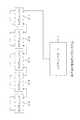
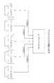
図1は本発明の好ましい実施形態に係るカメラシステムの概略構成図である。このシステムは、カメラコントローラ1に1つのカメラユニット2−1が接続され、カメラユニット2−1にはカメラユニット2−2が、カメラユニット2−2にはカメラユニット2−3、カメラユニット2−3にはカメラユニット2−4・・と、カメラコントローラ1を起点にして、順次カメラユニットが、1方向のみの高速シリアル通信経路(好ましくは、ザインエレクトロニクス株式会社の「v−by−one(登録商標)」)で数珠繋ぎに接続されることで構成される。 FIG. 1 is a schematic configuration diagram of a camera system according to a preferred embodiment of the present invention. In this system, one camera unit 2-1 is connected to the
v−by−oneは、3ビットの同期信号と18ビットのデータを最大880メガビット/秒の速度で通信する方式である。従来のIEEE1394、USB2.0、LVDS(Low Voltage Differential Signaling:低電圧差動信号データ転送)などとは異なり、同期通信機能のみをサポートしており、制御が簡単である。 v-by-one is a method of communicating a 3-bit synchronization signal and 18-bit data at a maximum speed of 880 megabits / second. Unlike conventional IEEE 1394, USB 2.0, LVDS (Low Voltage Differential Signaling), etc., only the synchronous communication function is supported and the control is simple.
図1は5つのカメラユニット2−1〜2−5が、カメラコントローラ1を起点に順次接続されているが、接続するカメラユニット2−n(n=1,2・・,Nであり、Nは正の整数。nの表記を省略し、カメラユニット2と総称することもある)は当然ながら5つに限らず、1または複数個であれば何個でもよい。最初に接続されたカメラユニット2を先頭のカメラユニット2といい、最後に接続されたカメラユニット2を末端のカメラユニット2という。 In FIG. 1, five camera units 2-1 to 2-5 are sequentially connected starting from the
図2はカメラコントローラ1とカメラユニット2の接続形態の詳細を示す。各カメラユニット2−nは、ch1受信ポートch1−R−n、ch1送信ポートch1−S−n、ch2受信ポートch2−R−n、およびch2送信ポートch2−S−nを有している。 FIG. 2 shows details of the connection form between the
ch1受信ポートch1−R−nは、カメラコントローラ1のch1送信ポートch1−S−0ないし先頭側のカメラユニット2−(n−1)からのデータを、1方向のみのシリアル通信経路を介して受信するためのポートである。ch1送信ポートch1−S−nは、ch1受信ポートch1−R−nで受信したデータに、カメラユニット2−n自身が各種のデータを付加するか、あるいは何も付加しないまま、1方向のみのシリアル通信経路を介して、末端側のカメラユニット2−(n+1)に送出するためのポートである。 The ch1 reception port ch1-Rn receives data from the ch1 transmission port ch1-S-0 of the
ch2受信ポートch2−R−nは、末端側のカメラユニット2−(n+1)からのデータを、1方向のみのシリアル通信経路を介して受信するためのポートである。ch2送信ポートch2−S−nは、ch2受信ポートch2−R−nで受信したデータに、カメラユニット2−n自身が各種のデータを付加するか、あるいは何も付加しないまま、1方向のみのシリアル通信経路を介して、先頭側のカメラユニット2−(n−1)のch2受信ポートch2−R−(n−1)に向けて送出するためのポートである。 The ch2 reception port ch2-Rn is a port for receiving data from the camera unit 2- (n + 1) on the terminal side via a serial communication path in only one direction. The ch2 transmission port ch2-Sn is used only in one direction with the camera unit 2-n adding various data to the data received at the ch2 reception port ch2-Rn or adding nothing. This is a port for sending out to the ch2 reception port ch2-R- (n-1) of the camera unit 2- (n-1) on the head side via the serial communication path.
以後、コントローラ1のch1送信ポートch1−S−0を先頭に、順次ch1受信ポートch1−Rとch1送信ポートch1−Sとが接続されて末端のカメラユニット2−Nのch1受信ポートch1−R−Nに到達する通信経路をch1と呼ぶ。 Thereafter, the ch1 transmission port ch1-S-0 of the
末端のカメラユニット2−N(この図ではN=16)では、ch1送信ポートch1−S−Nとch2受信ポートch2−R−Nとが互いに接続されている。以下、これを末端ループと呼ぶこともある。 In the terminal camera unit 2-N (N = 16 in this figure), the ch1 transmission port ch1-SN and the ch2 reception port ch2-RN are connected to each other. Hereinafter, this may be referred to as a terminal loop.
末端のカメラユニット2−Nがデータを受信すると、別のデータを付加するか、あるいは何もせぬまま、ch2送信ポートch2−N−Sを介して、前のカメラユニット2−(N−1)のch2受信ポートch2−(N−1)−Rに戻す。 When the terminal camera unit 2-N receives the data, the other camera unit 2- (N-1) is added via the ch2 transmission port ch2-NS without adding another data or doing anything. To the ch2 reception port ch2- (N-1) -R.
以後、各カメラユニット2は、ch2受信ポートch2−Rとch2送信ポートch2−Sを介して、コントローラ1に向けてデータを回送する。 Thereafter, each
末端のカメラユニット2−Nを先頭に、順次ch2受信ポートch2−Rとch1送信ポートch2−Sとが接続されてコントローラ1のch1受信ポートch1−R−0に到達する通信経路をch2と呼ぶ。 A communication path in which the ch2 reception port ch2-R and the ch1 transmission port ch2-S are sequentially connected starting from the end camera unit 2-N and reach the ch1 reception port ch1-R-0 of the
つまり本システムでは、コントローラ1から発信されたデータは、カメラユニット2のch1受信ポートch1−Rとch1送信ポートch1−Rを介して、末端側のカメラユニット2−Nに到達する。その間、データには、各カメラユニット2が受信データに別のデータを付加して送信したり、あるいは何もせぬまま次のカメラユニット2に送信することができる。 That is, in this system, the data transmitted from the
ch1を構成する有線およびch2を構成する有線は、ツイストペアケーブルのように1本のケーブルにまとめることができる。従って、カメラユニットを1本の線で数珠繋ぎにするだけで本システムが構成でき、コントローラ1を中心にしたスター型接続のような複雑な配線は必要ない。 The wires constituting ch1 and the wires constituting ch2 can be combined into one cable like a twisted pair cable. Therefore, the present system can be configured only by connecting the camera units with a single line, and complicated wiring such as a star connection centering on the
図3は各カメラユニット2に共通するブロック構成を示した図である。カメラユニット2は、CPUを持たず、コントローラ1から送信されるレンズ駆動指示、撮像指示などの各種指示によって制御されることが特徴である。また、RGB信号をYC信号に変換する信号処理部を備えておらず、この変換はコントローラ1で行われる。 FIG. 3 is a diagram showing a block configuration common to the
カメラユニット2の正面に配備されたレンズ鏡胴60には、ズームレンズ101a及びフォーカスレンズ101bを含む撮影レンズ101が内蔵されており、ズームレンズ101aをズームレンズ用アクチュエータ110が光軸方向に移動させることで焦点距離調節が行なわれるとともに、フォーカスレンズ101bをフォーカスレンズ用アクチュエータ111が光軸方向に移動させることによりピント調節が行なわれる。焦点距離調節・ピント調節の指示は、コントローラ1から送信される。 A
メカシャッター131は、メカシャッター用アクチュエータ112により駆動され、コントローラ1から(あるいは操作釦104でも可)の撮像指示に応じたシャッター動作を行う。 The mechanical shutter 131 is driven by a
ズームレンズ用アクチュエータ110、フォーカスレンズ用アクチュエータ111、メカシャッター用アクチュエータ112の駆動は、コントローラ1がドライバー137a、137b、137cのそれぞれに制御信号を送ることで開始または停止する。 Driving of the
撮像素子にCCD132を用いた場合には、色偽信号やモアレ縞等の発生を防止するために、入射光内の不要な高周波成分を除去する光学的ローパスフィルタ(OPLF)132aが配設されている。また、入射光内の赤外線を吸収若しくは反射して、長波長域で感度が高いCCD132固有の感度特性を補正する赤外カットフィルタ132bが配設されている。光学的ローパスフィルタ132a及び赤外カットフィルタ132bの具体的な配設の態様は特に限定されない。 When the
CCD132の受光面には、多数のフォトセンサが2次元的に配列されており、受光面に入射された被写体光は、各フォトセンサによって入射光量に応じた量の信号電荷に変換される。そして、各フォトセンサに蓄積された信号電荷は、タイミングジェネレータ(TG)46から与えられるタイミングパルスに従って読み出され、垂直転送路及び水平転送路を介して信号電荷に応じた電圧信号(画像信号)として出力される。 A number of photosensors are two-dimensionally arranged on the light receiving surface of the
また、カメラユニット2には、CCD132からのアナログ信号に対してCDS処理・ゲイン処理などを行うとともに、ディジタルのR,G,B画像データにA/D変換するAFE134と、AFE134からのRGB画像信号をカメラコントローラがYC画像信号に変換して送出してきたYC画像信号、あるいはRGB補間処理が行われていないCCD−RAWデータを、SDRAMなどで構成されたメモリ135に格納したり、メモリ135のCCD−RAWデータやYC画像信号を読み取って出力する制御などを行うフレームメモリ制御部20が備えられている。 The
Hドライバー15は、CCD132を構成する各画素の電荷を水平方向へ転送するためのドライバーである。また、Vドライバー16は各画素の電荷を垂直方向へ転送するためのドライバーである。CCD132に蓄積された各画素の電荷信号は、Hドライバー15およびVドライバー16から出力される駆動信号によって図示せぬ垂直レジスタと水平レジスタを介してライン単位でA/D変換部134に出力される。 The
カメラユニット2には、ch1通信用レシーバーch1−Rあるいはch2通信用レシーバーch2−Rの受信したデータに基づいて各種のデータ処理を行ない、その処理内容を保持するレジスタ群を有するデータ処理部13が備えられている。 The
カメラユニット2は、上述したch1送信ポートch1−Sを介してパケットデータを送信するch1通信用トランスミッターT1、ch1受信ポートch1−Rを介してパケットデータを受信するch1通信用レシーバーR1、ch2受信ポートch2−Rを介してパケットデータを受信するch2通信用レシーバーR2、ch2送信ポートch2−Sを介してパケットデータを送信するch2通信用トランスミッターT2を備えている。 The
ch1通信用レシーバーR1あるいはch2通信用レシーバーR2の受信したパケットデータは、順次、通信制御部14が有するFIFOメモリに格納される。通信制御部14は、FIFOメモリへのデータ入力順に基づいて、元のデータを復元し、復元したデータをデータ処理部13に出力する。 The packet data received by the ch1 communication receiver R1 or the ch2 communication receiver R2 is sequentially stored in the FIFO memory of the
また、ch1通信用トランスミッターT1あるいはch2通信用トランスミッターT2を介して送出すべき所望のデータが、データ処理部13から通信制御部14に入力されると、通信制御部14は、このデータを固定長のデータパケットに分割し、先頭のパケットデータから順次FIFOメモリに格納する。そして、このデータパケットは、順次ch1通信用トランスミッターT1あるいはch2通信用トランスミッターT2によって出力される。 When desired data to be transmitted via the ch1 communication transmitter T1 or the ch2 communication transmitter T2 is input from the
カメラユニット2はビデオエンコーダ50を備えている。ビデオエンコーダ50は、メモリ135に入力されたYC画像信号をNTSC(National TV Standards Committee)信号に変換し、ビデオアウト端子51を介して、外部の表示装置に供給し、当該画像信号に基づく映像を表示させる。 The
DC−DCコンバータ71は、コントローラ1のDC電源72を供給元として電源を各ブロックに供給する。 The DC-
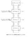
図4はカメラコントローラ1のブロック構成図である。 FIG. 4 is a block diagram of the
CPU71はカメラコントローラ1全体を制御する。ROM72はシステムの制御プログラム等が格納されている。メモリ74はCPU71が演算動作をするのに必要なデータを一時記憶する。 The
DMAC(ダイレクトメモリアクセスコントローラ)81は、ch2受信ポートch2−R−0から入力された画像データ等の各種データを、メモリ74に直接書き出すという動作を実行する。 A DMAC (direct memory access controller) 81 executes an operation of directly writing various data such as image data input from the ch2 reception port ch2-R-0 to the
信号処理部75は、ch2受信ポートch2−R−0から入力されたCCD−RAW画像データ等に各種の処理を施す。例えば、各カメラユニット2から受信したCCD−RAWを、時分割処理(タイムシェアリング)によってそれぞれYC信号に変換し、得られたYC信号を、DMAC81がいったんメモリ74に書き出した上で、ch1経由で各カメラユニット2に転送する。カメラユニット2は、コントローラ1から受信したYC信号を各自のメモリ135に保存しておくこともできる。 The signal processing unit 75 performs various processes on the CCD-RAW image data and the like input from the ch2 reception port ch2-R-0. For example, the CCD-RAW received from each
カメラユニット2のYC信号に基づいた映像をLCDモニター83に表示したい場合は、カメラユニット2からカメラコントローラ1にYC信号をch2経由で送信し、これをそのままカメラコントローラ1の表示制御部79に出力すればよい。あるいは、カメラユニット2に転送されたYC信号をビデオアウト端子51経由で外部表示装置に出力し、カメラユニット2ごとに撮影した画像を出力することも可能である。 In order to display an image based on the YC signal of the
本システムでは、各カメラユニット2は信号処理部75を備える必要がないし、カメラコントローラ1も各カメラユニット2のYC信号を全部保存しておくためのメモリを備える必要がなく、メモリ容量を削減できる。 In this system, each
画像圧縮処理部77は、画像データをJPEGなどの所定の形式で圧縮符号化された画像ファイルに変換し、ストレージ制御部78を介して記録メディア82に該画像ファイルを記録する。 The image
表示制御部79は、ビデオエンコーダを有しており、メモリ74に記憶された画像データをNTSC信号に変換し、外部のLCDモニター83に供給することで、当該画像信号に基づく映像を表示させる。 The
なお、カメラユニット2のメモリ135に記憶されているYC信号をそのままコントローラ1に送信し、コントローラ1は、受信したYC信号をそのまま表示制御部79に出力すれば、各カメラユニット2の撮影した画像を直ちに表示させることができ、カメラユニット2の設置確認などに便利である。 If the YC signal stored in the
PIO(Parallel I/O)80は、操作パネル84からバスインターフェース90を介したCPU71への入力信号の転送を管理する。 A PIO (Parallel I / O) 80 manages the transfer of input signals from the
AC/DCコンバータ76は、AC電源の電圧を変換してコントローラ1およびカメラユニット2に必要な各種の電圧を発生し、カメラユニット用DC電源91に接続されたDC電源端子72を介して、数珠繋ぎにされた各カメラユニット2に順次電源を供給する。 The AC /
ch1通信用ドライバー87は、通信制御部14の制御に基づいて、送信すべき所望のデータを固定長のデータパケットに分割し、ch1送信ポートch1−S−0を介してパケットをカメラユニット2に送出する。 The ch1 communication driver 87 divides the desired data to be transmitted into fixed-length data packets based on the control of the
また、ch2通信用レシーバー88がch2受信ポートch2−R−0を介して受信したデータパケットは、通信制御部85によって元のデータに復元され、メモリ74に格納される。 The data packet received by the ch2 communication receiver 88 via the ch2 reception port ch2-R-0 is restored to the original data by the
同期信号発生部86は、所望のデータを分割して作成されたデータパケットに、カメラユニット2の同期信号のパケットを挿入する。詳細は後述する。 The synchronization
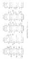
図5は、本システムにおけるカメラユニット認識シーケンスを示す説明図である。 FIG. 5 is an explanatory diagram showing a camera unit recognition sequence in the present system.
ch1では、コントローラ1を起点に、数珠繋ぎにされたカメラユニット2に対し、順次データパケットが回送される。あるカメラユニット2が上流側の機器(コントローラ1に近い方)からパケットを受信すると、そのカメラ2は、受信したパケットに任意のデータを付加することができる。 In ch1, data packets are sequentially sent to the
図2では一例として、本システムの起動時に実行されるハンドシェークの流れを示す。この処理では、カメラコントローラ1が、接続されたカメラユニット2の総台数を認識するときのパケットを巡回させるとともに、各カメラユニット2は、自身の識別情報を獲得して、自身のレジスタに格納する。 As an example, FIG. 2 shows the flow of handshaking executed when the present system is activated. In this process, the
まずカメラコントローラ1は、同期信号発生部86によって通信用の同期信号を送出した後、接続ID番号P_IDの初期値(典型的には0)とカメラ認識パケットを、最初に接続されているカメラユニット2−1に送信する。 First, after sending a synchronization signal for communication by the
カメラユニット2−1は、接続ID番号P_IDを含んだカメラ認識パケットを受信すると、直ちにNOP(No operation)のパケットの挿入を開始する。カメラユニット2−1は、そのNOPパケットを挿入している間に、受信したカメラ認識パケットの中のP_IDを読み出して、その初期値0に1を加算し、この値「1」を自分自身の識別情報(接続ID)としてデータ処理部13のレジスタに格納する。さらにその値をカメラ認識パケットの新しいP_IDとして書き換え、そのP_IDを含んだカメラ認識パケットをカメラユニット2−2に送信する。 Upon receiving the camera recognition packet including the connection ID number P_ID, the camera unit 2-1 immediately starts inserting a NOP (No operation) packet. While inserting the NOP packet, the camera unit 2-1 reads P_ID in the received camera recognition packet, adds 1 to its
従って、図2に示すように、P_IDが「1」のカメラ認識パケットがカメラユニット2−1からカメラユニット2−2に送られる。各カメラユニット2でパケットのデータを書き換えるには、後述の「間接接続モード」によって行われる。 Therefore, as shown in FIG. 2, a camera recognition packet with P_ID “1” is sent from the camera unit 2-1 to the camera unit 2-2. The rewriting of packet data by each
カメラユニット2−2は、カメラユニット2−1からカメラ認識パケットを受信すると、カメラユニット2−1と同様、直ちにNOP(No operation)のパケットの挿入を開始する。カメラユニット2−2は、そのNOPパケットを挿入している間に、受信したカメラ認識パケットの中のP_IDを読み出して、その値に1を加算し、この値「2」を自身の接続IDとしてデータ処理部13のレジスタに格納する。 Upon receiving the camera recognition packet from the camera unit 2-1, the camera unit 2-2 immediately starts inserting a NOP (No operation) packet, as with the camera unit 2-1. While inserting the NOP packet, the camera unit 2-2 reads P_ID in the received camera recognition packet, adds 1 to the value, and sets this value “2” as its connection ID. Store in the register of the
さらにその値をカメラ認識パケットの新しいP_IDとして書き換え、そのP_IDを含んだカメラ認識パケットをカメラユニット2−3に送信する。従って、図2に示すように、P_IDが「2」のカメラ認識パケットがカメラユニット2−2からカメラユニット2−3に送られる。 Further, the value is rewritten as a new P_ID of the camera recognition packet, and the camera recognition packet including the P_ID is transmitted to the camera unit 2-3. Therefore, as shown in FIG. 2, a camera recognition packet with P_ID “2” is sent from the camera unit 2-2 to the camera unit 2-3.
カメラユニット2−3は、カメラユニット2−2からカメラ認識パケットを受信すると、カメラユニット2−1と同様、直ちにNOP(No operation)のパケットの挿入を開始する。カメラユニット2−3は、そのNOPパケットを挿入している間に、受信したカメラ認識パケットの中のP_IDを読み出して、その値に1を加算し、この値「3」を自身の接続IDとしてデータ処理部13のレジスタに格納する。さらにその値をカメラ認識パケットの新しいP_IDとして書き換え、そのP_IDを含んだカメラ認識パケットを、ch2経由でカメラユニット2−2に送信する。 Upon receiving the camera recognition packet from the camera unit 2-2, the camera unit 2-3 immediately starts inserting a NOP (No operation) packet, as with the camera unit 2-1. While inserting the NOP packet, the camera unit 2-3 reads the P_ID in the received camera recognition packet, adds 1 to the value, and uses this value “3” as its connection ID. Store in the register of the
従って、図2に示すように、P_IDが「3」のカメラ認識パケットがカメラユニット2−3からカメラユニット2−2に送られる。 Therefore, as shown in FIG. 2, a camera recognition packet with P_ID “3” is sent from the camera unit 2-3 to the camera unit 2-2.
なお、NOPを挿入することによる各カメラユニットの動作の同期化については、後述する。 Note that the synchronization of the operation of each camera unit by inserting a NOP will be described later.
カメラユニット2−3からカメラユニット2−2に送られたカメラ認識パケットには、カメラユニット2−2の固有の接続IDが付されて、ch2経由でカメラユニット2−1に回送される。カメラユニット2−2からカメラユニット2−1に送られたカメラ認識パケットには、カメラユニット2−1の接続IDがさらに付加され、カメラコントローラ1に回送される。 The camera recognition packet sent from the camera unit 2-3 to the camera unit 2-2 is given a unique connection ID of the camera unit 2-2, and is sent to the camera unit 2-1 via ch2. The connection ID of the camera unit 2-1 is further added to the camera recognition packet sent from the camera unit 2-2 to the camera unit 2-1 and forwarded to the
末端側のカメラユニット2−3から送出されたP_IDを含むカメラ認識パケットは、カメラユニット2−2・2−1を介して、上流側の機器であるカメラコントローラ1に到達する。 The camera recognition packet including P_ID transmitted from the terminal side camera unit 2-3 reaches the
カメラコントローラ1は、この末端側のカメラユニット2−3から送出されたカメラ認識パケットから接続IDを抽出することで、接続された全てのカメラユニット2の各々に固有の接続IDや、それらの状態(総計で何台接続されているのかなど)を認識することができる。 The
また、各カメラユニット2は、接続IDに対応した補正データ(例えばCCDの感度差データ、ホワイトバランスデータ、CCDキズ座標データ、レンズ特性データ)を、予めカメラコントローラ1からダウンロードしておくことで、各カメラユニット2で撮影した画像データへの個別的な補正や調整値の反映が可能となる。 Each
なお、各カメラユニット2−1〜2−3は、ch1から出力したP_IDとch2から受信したP_IDとを比較し、これらが一致している場合は、自分自身を末端カメラユニットであると認識し、一致しなければ、自分自身を末端でないカメラユニット(中継カメラユニット)であると認識する。自分自身が末端であると認識したカメラユニット2は、後述の使用権の調停を行う。 Each camera unit 2-1 to 2-3 compares the P_ID output from ch1 and the P_ID received from ch2, and if they match, recognizes itself as a terminal camera unit. If they do not match, it recognizes itself as a non-terminal camera unit (relay camera unit). The
図6は、カメラユニット2の間接接続モードおよび直接接続モードの概念説明図である。 FIG. 6 is a conceptual explanatory diagram of the indirect connection mode and the direct connection mode of the
スイッチSWは、レシーバーR(ch1またはch2を含む)とトランスミッターT(ch1またはch2を含む)を、通信制御部14を経由して接続する端子SW1と、通信制御部14を経由しないで直接接続する端子SW2と、を備える。 The switch SW directly connects the receiver R (including ch1 or ch2) and the transmitter T (including ch1 or ch2) to the terminal SW1 that connects via the
通信制御部14は、必要に応じて、間接接続モードまたは直接接続モードを設定し、間接接続モードの場合は端子SW1側へ、直接接続モードの場合は端子SW2側へスイッチSWが接触するよう制御する。 The
間接接続モードでは、通信制御部14がレシーバーRによりパケットを受信した後、その内容に応じて任意のパケットを挿入してトランスミッターTから送出できるから、上述したカメラ台数の認識シーケンス、後述する通信チャンネルの調停、撮影のためのレジスタ設定のようにパケットデータのブロードキャスト(一斉送信)が必要な場合に用いられる。 In the indirect connection mode, after the
直接接続モードでは、レシーバーRにより受信したパケットを、そのままトランスミッターSから送出できるから、各カメラユニット2からカメラコントローラ1への画像データの転送など、特定のカメラユニット2が、間に別のカメラユニット2を挟んでカメラコントローラ1とのデータの転送経路を確保する(ハンドシェーク)を可能にするとともに、その場合の各カメラユニット2のオーバーヘッド(負荷)を軽減できる。説明の簡略化のため、直接接続モードで伝送されるデータパケットは、特定のカメラユニット2からカメラコントローラ1に転送されるものに限られるとする。 In the direct connection mode, the packet received by the receiver R can be sent out from the transmitter S as it is, so that the
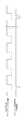
図7は、コントローラ1からある1つの特定のカメラユニット2に、画像データなどの各種データの送信を要求し、この要求に応じて、特定のカメラユニット2がデータをコントローラ1に転送する転送シーケンスを説明する。このシーケンスは、転送要求フェーズ、転送フェーズ、および開放フェーズを含む。 FIG. 7 shows a transfer sequence in which the
まず、転送要求フェーズでは、コントローラ1が、ch2における間接接続モードの使用権の調停を要求するパケットを、ch1経由で末端カメラユニットに送出する。このパケットには、データの要求の対象となるカメラユニット2の識別情報を有する要求情報が含まれている。要求情報は転送すべきデータの種類の識別情報などその他の情報を有していてもよい。 First, in the transfer request phase, the
末端以外のカメラユニットである中継カメラユニットのch1レシーバーRは、直接モードで、ch1トランシーバーTと接続され、コントローラ1から送出された要求情報のパケットを、そのまま末端カメラユニット2(ここでは2−3)に回送する。 The ch1 receiver R of the relay camera unit which is a camera unit other than the terminal is connected to the ch1 transceiver T in the direct mode, and the request information packet sent from the
末端カメラユニット2−3は、受信したパケットから、データの要求の対象となるカメラユニット2の識別情報を識別する。そしてこの識別情報を、ch2における間接接続モードの使用権を獲得したカメラユニット2の識別情報として、ch2経由で、コントローラ1に送る。 The terminal camera unit 2-3 identifies the identification information of the
カメラコントローラ1は、使用権を獲得したカメラユニット2の識別情報を受信することで、間接接続モードの使用権の調停が完了したことを確認する。この確認が終わることで、転送フェーズが開始する。 The
転送フェーズでは、まずカメラコントローラ1が、使用権を獲得したカメラユニット2に対し、データの転送をするよう要求するパケット(転送要求パケット)をch1経由で送出する。 In the transfer phase, first, the
各カメラユニット1は、転送要求パケットに含まれる識別情報と、レジスタに記憶されている識別情報とを比較する。そして、両者が一致していれば、ch2レシーバーR・ch2トランスミッターTに間接接続モードを設定する。両者が一致していなければ、ch2レシーバーR・ch2トランスミッターTに直接接続モードを設定する。 Each
なお、間接接続モードが設定されたカメラユニットよりも末端側のカメラユニット2は、データ転送に関係しない。 Note that the
間接接続モードの使用権に従って各カメラユニット2に間接接続モードあるいは直接接続モードが設定されると、データ転送が開始できる状態になる。図7では一例として、カメラユニット2−2から、カメラユニット2−1を経由して、データ転送パケットが送信される。 When the indirect connection mode or the direct connection mode is set for each
カメラコントローラ1がデータの転送完了を確認すると、開放フェーズに移行する。開放フェーズでは、カメラコントローラ1が各カメラユニット2に対し、ch2の開放を指示するパケットを、ch1経由で送出する。 When the
各カメラユニット2は、この開放指示に応じて、ch2レシーバーRおよびch2トランシーバーTを、直接接続モードに設定する。この設定が完了することで、開放フェーズが終わる。 Each
図8は転送シーケンスの他の例であり、複数のカメラユニット2にデータ転送要求をする場合を示す。 FIG. 8 shows another example of the transfer sequence, and shows a case where a data transfer request is made to a plurality of
まず、転送要求フェーズでは、末端カメラユニット2−3が、全てのデータ転送要求対象のカメラユニット2の識別情報をパケットから復元し、その中から、所定の順番に従って(例えば先頭側のカメラユニットから)カメラユニット2に1つずつ使用権を設定する。使用権の設定されたカメラユニットの識別情報には、使用権が設定されたことを示すフラグが対応づけられ、レジスタに記憶される。この図では2つのカメラユニット2−1および2−3がデータ転送の要求対象であり、まず、先頭側のカメラユニット2に使用権のフラグが立てられる。使用権のフラグが立つと転送要求フェーズが完了し、転送フェーズに移行する。 First, in the transfer request phase, the end camera unit 2-3 restores the identification information of all the
転送フェーズでは、使用権の設定されたカメラユニット2−1からコントローラ1にデータが転送される。 In the transfer phase, data is transferred to the
1つ目のカメラユニット2−1の転送が完了すると、再調停フェーズに移行する。まず、コントローラ1は、ch2の使用権の開放を指示するパケットをch1経由で各カメラユニット2に送信する。 When the transfer of the first camera unit 2-1 is completed, the process proceeds to the re-arbitration phase. First, the
末端カメラユニット2−3は、開放指示のパケットを受信すると、現在使用権が設定されているカメラユニット2−1のフラグを消去し、次の順番のカメラユニット2−3に使用権のフラグを設定する。これをもって再調停フェーズが完了し、転送フェーズに移行する。 When the end camera unit 2-3 receives the release instruction packet, the end camera unit 2-3 deletes the flag of the camera unit 2-1 to which the right of use is currently set, and sets the right of use to the next camera unit 2-3. Set. This completes the re-arbitration phase and shifts to the transfer phase.
転送フェーズでは、使用権の設定されたカメラユニット2−3からコントローラ1にデータが転送される。 In the transfer phase, data is transferred to the
データの転送が完了すると、開放フェーズに移行する。この動作の内容は図7と同様である。 When the data transfer is completed, the process proceeds to the release phase. The contents of this operation are the same as in FIG.
図9は、通信パケット転送時における各カメラユニット2のパケットデータ処理方法を示す。 FIG. 9 shows a packet data processing method of each
この図に示すように、もしカメラユニット2−1が、コントローラ1から受信したパケットに、間接接続モードで、上述のカメラユニットの識別情報など何らかのデータを追加したい場合は、パケット受信後直ちにNOPパケットを挿入して次に接続されている末端側の次のカメラユニット2−2に送出するとともに、NOPパケットを挿入している間に、例えば上述した識別情報のインクリメントなど、各種の受信データ処理をする。その処理が終わると、処理後のデータパケットを挿入し、次のカメラユニット2−2に送出する。 As shown in this figure, if the camera unit 2-1 wants to add some data such as the above camera unit identification information to the packet received from the
次のカメラユニット2−2は、NOPパケットを受信している間は、データパケットを受信するまで、何の処理も行わずに待機する。 While receiving the NOP packet, the next camera unit 2-2 waits without performing any processing until receiving the data packet.
カメラユニット2−2が、カメラユニット2−1から受信したパケットに、何らかのデータを追加したい場合も、上記と同様にする。すなわち、パケット受信後直ちにNOPパケットを送出するとともに、NOPパケットを挿入している間に、各種の受信データ処理をし、その処理が終わると、処理後のデータパケットをして次のカメラユニット2−3に送出する。 The same applies to the case where the camera unit 2-2 wants to add some data to the packet received from the camera unit 2-1. That is, a NOP packet is sent out immediately after receiving a packet, and various received data processing is performed while the NOP packet is being inserted. When the processing is completed, the processed data packet is processed and the
次のカメラユニット2−3は、NOPパケットを受信している間は、データパケットを受信するまで、何の処理も行わずに待機する。 While the next camera unit 2-3 receives the NOP packet, it waits without performing any processing until it receives the data packet.
このように、前のカメラユニット2が、データ処理中は、次のカメラユニット2にNOPを送出することで、次のカメラユニット2で処理が待機されるから、数珠繋ぎにされたカメラユニット2間でデータを加工してシリアル転送する際にも、各カメラユニット2での処理の時間を確保することができる。 In this way, while the
なお、カメラユニット2間でデータを転送する際に通信エラーが発生した場合は、次のようにして修復を行うとよい。 If a communication error occurs when data is transferred between the
各カメラユニット2の通信制御部14は、CRC(Cyclic Redundancy Check)などによって通信パケット内の誤りを検出する。あるカメラユニット2が誤りを検出したと判断した場合、そのカメラユニット2は、パケットの割り込み同期信号をアサート(有効)にし、ch1経由で末端側のカメラユニット2に送出する。 The
その割り込み同期信号を受信した末端側のカメラユニット2は、順次割り込み同期信号を末端側のカメラユニット2に送る。これが繰り返されることで、割り込み同期信号が末端カメラユニット2に到達する。 The terminal-
末端カメラユニット2は、割り込み同期信号をそのままch2経由でコントローラ1まで送る。 The
コントローラ1は、ch2経由で割り込み同期信号を受信すると、誤りを検出したカメラユニット2に割り込み情報確認パケット(図10参照)をch1経由で送信する。 When the
カメラユニット2は、割り込み情報確認パケットを受信すると、レジスタに誤りフラグが立っているか否かを判断し、誤りフラグが立っている場合は、割り込み情報確認パケットに、自己の識別情報と、誤りが検出されたことを示すフラグ「1」をセットして、末端側のカメラユニット2にch1経由で送信する。これが各カメラユニット2で繰り返されることで、割り込み同期信号が末端カメラユニット2に到達する。 Upon receipt of the interrupt information confirmation packet, the
末端カメラユニット2は、割り込み情報確認パケットをそのままch2経由でコントローラ1まで送る。 The
カメラコントローラ1は、パケットの割り込み同期信号を発生させたカメラユニット2に対してステータス情報の転送を要求し、どの割り込みが発生したかを確認する。 The
図10は、本システムで送受信されるパケットの構造を示している。これらのパケットはいずれも有効なデータの前に識別マーカーを挿入している。これにより、通信制御部14のパケットデータ認識動作を簡単に素早く実施させることができる。 FIG. 10 shows the structure of a packet transmitted and received in this system. In each of these packets, an identification marker is inserted before valid data. Thereby, the packet data recognition operation of the
図11は本システムを構成する各カメラユニット2による撮影の同期方法を示す。 FIG. 11 shows a method of synchronizing shooting by each
まず、v−by−oneのように、受信側に基準クロック自体が不要な通信方式によって、コントローラ1から各カメラユニット2に、通信用同期信号をブロードキャストする。かつ、コントローラ1は、TG46の発生するCCD132の駆動タイミング信号を周期的にリセットするためのリセット信号を、各カメラユニット2に送る。 First, a communication synchronization signal is broadcast from the
各カメラユニット2のTG46は、自身の発生する駆動信号のクロック周波数を、受信した通信用同期信号のクロック周波数と同一にするよう構成されている。こうすると、撮影制御の同期化がとりやすい。 The TG 46 of each
各カメラユニット2は、コントローラ1からの周期的なリセット信号によって、TG46の発生する駆動信号の発生タイミングをリセットする。よってこれ以後、各カメラユニット2の駆動クロック信号の発生タイミングが完全に同期し、同一被写体を多数のカメラユニット2で同時に撮影したい場合などは便利である。 Each
なお、さらに、通信用同期信号のクロック周波数を、CCD132から取得される動画データのフレームレート(例えば30フレーム/秒)と同じにすれば、動画撮影時の同期も可能になる。 Furthermore, if the clock frequency of the communication synchronization signal is made the same as the frame rate (for example, 30 frames / second) of the moving image data acquired from the
カメラユニット2の交換時の電源制御動作は次のようにするとよい。 The power control operation when the
ch1の有線ケーブル、またはch2の有線ケーブルを外すと、それよりも末端側のカメラユニット2とコントローラ1との通信が不能になる。 When the ch1 wired cable or the ch2 wired cable is disconnected, communication between the
コントローラ1は、通信用同期信号を送信する唯一の機器であるから、これが遮断されたことを検知することにより、容易にカメラユニット2が切り離されたことを検知できる。 Since the
コントローラ1は、カメラユニット2が切り離されたことを検知すると、DC電源91からの全カメラユニット2に対する電源供給を停止する。これにより、カメラユニット2の切り離しに応じたシステムの電源切断を実行することができる。 When the
一方、電源投入動作は次のようにする。すなわち、コントローラ1は、DC電源91からの電源供給開始を周期的(例えば1分に一回)に行う。この場合、接続されているカメラユニット2のみが動作することになる。次に、ch1経由で通信同期信号を一定時間(例えば10秒間)送信し、ch2経由で通信同期信号が戻ってきたか否かを確認する。通信同期信号が戻って来た場合は、カメラユニット認識シーケンスに移行する。 On the other hand, the power-on operation is as follows. That is, the
このようにして、任意のカメラユニット2の接続・取り外しに、DC電源91からの電源供給のオン・オフを対応させて、コントローラ1の電源を切らずにカメラユニット2の接続・取り外しを行うこと(ホットプラグ・ホットスワップ)を可能にする。 In this way, the connection / removal of the
1:カメラコントローラ、2:カメラユニット、87:ch1通信用ドライバー、88:通信用レシーバー、91:カメラユニット用DC電源1: Camera controller, 2: Camera unit, 87: Driver for ch1 communication, 88: Receiver for communication, 91: DC power supply for camera unit
Claims (12)
Translated fromJapanese前記一方向シリアル通信経路を介し、前記カメラユニットの各々とデータの通信を行うことが可能なカメラコントローラ通信部を備えるカメラコントローラと、
を備えるカメラシステム。An image sensor that converts a subject image received through an imaging lens into an image signal, and a camera unit communication unit that transmits and receives data including the image signal via a one-way serial communication path having a synchronous communication signal generation function. One or a plurality of camera units that can be sequentially connected to each other via the one-way serial communication path;
A camera controller comprising a camera controller communication unit capable of communicating data with each of the camera units via the one-way serial communication path;
A camera system comprising:
前記末端のカメラユニットでは、前記第1の通信経路と前記第2の通信経路とが接続している請求項1〜3のいずれかに記載のカメラシステム。The serial communication path includes a first communication path through which a packet is transmitted from the camera controller to a terminal camera unit, and a second communication path through which a packet is transmitted from the terminal camera unit to the camera controller. ,
The camera system according to claim 1, wherein the first communication path and the second communication path are connected to each other at the terminal camera unit.
前記カメラユニットは、前記第1の通信経路を介して前記パケットデータを受信すると、前記パケットデータに格納された識別番号をインクリメントしてレジスタに格納するとともに、インクリメントされた識別番号のパケットデータを、前記第1の通信経路を介して、末端のカメラユニットに送出し、
前記末端のカメラユニットは、前記第1の通信経路を介して前記パケットデータを受信すると、前記パケットデータに格納された識別番号をインクリメントし、インクリメントされた識別番号のパケットデータを、前記第2の通信経路を介して、カメラコントローラに送出し、
前記カメラコントローラは、前記第2の通信経路を介して前記末端のカメラユニットから受信した識別番号により、前記カメラユニットの総接続数を認識し、
前記カメラユニットは、前記レジスタに格納された識別番号を自己の識別番号とする請求項1〜4のいずれかに記載のカメラシステム。The camera controller sends out packet data storing an identification number of the camera unit via the first communication path,
When the camera unit receives the packet data via the first communication path, the camera unit increments the identification number stored in the packet data and stores the packet data in the register. Via the first communication path, sent to the terminal camera unit,
When the terminal camera unit receives the packet data via the first communication path, the terminal camera unit increments the identification number stored in the packet data, and transmits the packet data of the incremented identification number to the second data. Send it to the camera controller via the communication path,
The camera controller recognizes the total number of connections of the camera unit based on the identification number received from the terminal camera unit via the second communication path,
The camera system according to any one of claims 1 to 4, wherein the camera unit uses the identification number stored in the register as its own identification number.
前記同期通信信号の発生周期は前記タイミングパルスの発生周期と実質的に同一であり、
前記カメラコントローラは、前記タイミングジェネレータのタイミングパルスをリセットするリセット信号を、前記通信経路を介して周期的に送信し、
前記カメラユニットは、前記通信経路を介して前記リセット信号を受信すると、前記タイミングジェネレータは、前記リセット信号に同期して前記タイミングパルスの発生をリセットする請求項1〜5のいずれかに記載のカメラシステム。The camera unit includes a timing generator that generates a timing pulse for driving the imaging device,
The generation period of the synchronous communication signal is substantially the same as the generation period of the timing pulse,
The camera controller periodically transmits a reset signal for resetting the timing pulse of the timing generator via the communication path,
The camera according to claim 1, wherein when the camera unit receives the reset signal via the communication path, the timing generator resets the generation of the timing pulse in synchronization with the reset signal. system.
前記スイッチ部は、前記カメラコントローラからの制御に応じ、前記受信部と前記送信部とを直接接続することで、前記第2の通信経路を介して前記末端のカメラユニットから前記コントローラに前記データを転送する請求項4または5に記載のカメラシステム。The camera unit communication unit receives data from a terminal camera unit via the second communication path, and receives data from the camera unit on the camera controller side via the second communication path. A transmission unit, and a switch unit capable of directly connecting the reception unit and the transmission unit,
The switch unit directly connects the receiving unit and the transmitting unit in accordance with control from the camera controller, so that the data is transferred from the terminal camera unit to the controller via the second communication path. The camera system according to claim 4 or 5, wherein the camera system is transferred.
前記カメラコントローラは、前記第1の通信経路を介し、前記調停部から通知されたカメラユニットから所望のデータを転送する要求を前記カメラユニットに送信し、
前記使用権の設定されたカメラユニットは、前記第2の通信経路を介し、要求されたデータを前記カメラコントローラに転送する請求項4に記載のカメラシステム。The terminal camera unit sets the right of use by any one of the camera controllers connected to the second communication path, and sets the camera unit identification number to which the right of use is set. It has an arbitration unit that notifies the controller,
The camera controller transmits a request to transfer desired data from the camera unit notified from the arbitration unit to the camera unit via the first communication path,
The camera system according to claim 4, wherein the camera unit to which the usage right is set transfers the requested data to the camera controller via the second communication path.
前記末端のカメラユニットは前記第2の通信経路を介して前記エラー発生通知を前記カメラコントローラに送信し、
前記カメラコントローラは、前記エラー発生通知を送信したカメラユニットに対し、ステータス情報の送信を要求する請求項4、8または9に記載のカメラシステム。The camera unit includes an error detection unit that detects whether or not an error has occurred during data reception, and the camera unit communication unit sends an error occurrence notification to the first communication when the error detection unit detects an error. Send to the end camera unit via the path,
The terminal camera unit transmits the error occurrence notification to the camera controller via the second communication path,
The camera system according to claim 4, wherein the camera controller requests the camera unit that has transmitted the error occurrence notification to transmit status information.
前記カメラユニットは、前記カメラコントローラから受信した処理済み画像データを表示装置に出力する画像出力部を有する請求項3に記載のカメラシステム。The control unit of the camera controller receives the image signal from each camera unit via the communication path, performs predetermined image processing on the image signal from each camera unit by a time division processing method, and performs the predetermined processing. Send the processed image data obtained to each camera unit,
The camera system according to claim 3, wherein the camera unit includes an image output unit that outputs processed image data received from the camera controller to a display device.
前記電源供給部は、前記通信経路を介した前記カメラコントローラと前記カメラユニットとの通信が断絶した場合、前記カメラユニットへの電源の供給を停止し、
前記カメラコントローラ通信部は、前記カメラユニットへの電源供給の停止後、前記通信経路を介して定期的に前記同期通信信号の送信を行い、
前記電源供給部は、前記通信経路を介して前記カメラユニットから前記同期通信信号が返送された場合、前記カメラユニットへの電源の供給を開始する請求項1〜11のいずれかに記載のカメラシステム。The camera controller further includes a power supply unit that supplies power by connecting to each camera unit,
When the communication between the camera controller and the camera unit via the communication path is interrupted, the power supply unit stops supplying power to the camera unit,
The camera controller communication unit periodically transmits the synchronous communication signal via the communication path after stopping the power supply to the camera unit,
The camera system according to claim 1, wherein the power supply unit starts supplying power to the camera unit when the synchronous communication signal is returned from the camera unit via the communication path. .
Priority Applications (1)
| Application Number | Priority Date | Filing Date | Title |
|---|---|---|---|
| JP2006257798AJP2008079142A (en) | 2006-09-22 | 2006-09-22 | Camera system |
Applications Claiming Priority (1)
| Application Number | Priority Date | Filing Date | Title |
|---|---|---|---|
| JP2006257798AJP2008079142A (en) | 2006-09-22 | 2006-09-22 | Camera system |
Publications (1)
| Publication Number | Publication Date |
|---|---|
| JP2008079142Atrue JP2008079142A (en) | 2008-04-03 |
Family
ID=39350698
Family Applications (1)
| Application Number | Title | Priority Date | Filing Date |
|---|---|---|---|
| JP2006257798APendingJP2008079142A (en) | 2006-09-22 | 2006-09-22 | Camera system |
Country Status (1)
| Country | Link |
|---|---|
| JP (1) | JP2008079142A (en) |
Cited By (9)
| Publication number | Priority date | Publication date | Assignee | Title |
|---|---|---|---|---|
| JP2011234347A (en)* | 2010-04-09 | 2011-11-17 | Sony Corp | Camera system, camera device, camera control unit and relay device |
| CN103376401A (en)* | 2013-07-03 | 2013-10-30 | 杨玉峰 | Method and device for automatically detecting 4K2K product main control board |
| KR20170035690A (en)* | 2015-09-23 | 2017-03-31 | 삼성전자주식회사 | Bidirectional Synchronizing Camera, Camera System including the Same and Method there-of |
| JP2017146420A (en)* | 2016-02-16 | 2017-08-24 | キヤノン株式会社 | Imaging device, lens unit, accessory, and method for controlling them, and imaging system |
| JP2018098730A (en)* | 2016-12-16 | 2018-06-21 | コニカミノルタ株式会社 | Image data transfer system and transmission method of image data |
| JP2020520565A (en)* | 2017-05-10 | 2020-07-09 | グラバンゴ コーポレイション | Series-configured camera array for efficient placement |
| WO2020174978A1 (en)* | 2019-02-27 | 2020-09-03 | 富士フイルム株式会社 | Imaging device, method for processing image data of imaging device, and program |
| CN113411556A (en)* | 2020-03-17 | 2021-09-17 | 瑞昱半导体股份有限公司 | Asymmetric image transmission method and electronic device thereof |
| US11481805B2 (en) | 2018-01-03 | 2022-10-25 | Grabango Co. | Marketing and couponing in a retail environment using computer vision |
- 2006
- 2006-09-22JPJP2006257798Apatent/JP2008079142A/enactivePending
Cited By (21)
| Publication number | Priority date | Publication date | Assignee | Title |
|---|---|---|---|---|
| US9344645B2 (en) | 2010-04-09 | 2016-05-17 | Sony Corporation | Camera system, camera device, camera controller and relay device |
| JP2011234347A (en)* | 2010-04-09 | 2011-11-17 | Sony Corp | Camera system, camera device, camera control unit and relay device |
| CN103376401A (en)* | 2013-07-03 | 2013-10-30 | 杨玉峰 | Method and device for automatically detecting 4K2K product main control board |
| KR102314611B1 (en)* | 2015-09-23 | 2021-10-18 | 삼성전자주식회사 | Bidirectional Synchronizing Camera, Camera System including the Same and Method there-of |
| KR20170035690A (en)* | 2015-09-23 | 2017-03-31 | 삼성전자주식회사 | Bidirectional Synchronizing Camera, Camera System including the Same and Method there-of |
| CN111866304B (en)* | 2015-09-23 | 2023-06-16 | 三星电子株式会社 | Two-way synchronous camera, camera system including the same, and method of operating the camera system |
| CN111866304A (en)* | 2015-09-23 | 2020-10-30 | 三星电子株式会社 | Bidirectional synchronized camera, camera system including the same, and method of operating the camera system |
| US11108935B2 (en) | 2015-09-23 | 2021-08-31 | Samsung Electronics Co., Ltd. | Bidirectional synchronizing camera, camera system including the same and method of operating the camera |
| JP2017146420A (en)* | 2016-02-16 | 2017-08-24 | キヤノン株式会社 | Imaging device, lens unit, accessory, and method for controlling them, and imaging system |
| JP2018098730A (en)* | 2016-12-16 | 2018-06-21 | コニカミノルタ株式会社 | Image data transfer system and transmission method of image data |
| JP7165140B2 (en) | 2017-05-10 | 2022-11-02 | グラバンゴ コーポレイション | Tandem Camera Array for Efficient Placement |
| JP2020520565A (en)* | 2017-05-10 | 2020-07-09 | グラバンゴ コーポレイション | Series-configured camera array for efficient placement |
| US11805327B2 (en) | 2017-05-10 | 2023-10-31 | Grabango Co. | Serially connected camera rail |
| US11481805B2 (en) | 2018-01-03 | 2022-10-25 | Grabango Co. | Marketing and couponing in a retail environment using computer vision |
| CN113475054A (en)* | 2019-02-27 | 2021-10-01 | 富士胶片株式会社 | Imaging device, image data processing method for imaging device, and program |
| US20210377430A1 (en)* | 2019-02-27 | 2021-12-02 | Fujifilm Corporation | Imaging apparatus, image data processing method of imaging apparatus, and program |
| WO2020174978A1 (en)* | 2019-02-27 | 2020-09-03 | 富士フイルム株式会社 | Imaging device, method for processing image data of imaging device, and program |
| US11711595B2 (en) | 2019-02-27 | 2023-07-25 | Fujifilm Corporation | Imaging apparatus, image data processing method of imaging apparatus, and program |
| US12273607B2 (en) | 2019-02-27 | 2025-04-08 | Fujifilm Corporation | Imaging apparatus, image data processing method of imaging apparatus, and program |
| CN113411556A (en)* | 2020-03-17 | 2021-09-17 | 瑞昱半导体股份有限公司 | Asymmetric image transmission method and electronic device thereof |
| CN113411556B (en)* | 2020-03-17 | 2023-09-05 | 瑞昱半导体股份有限公司 | Asymmetric image transmission method and electronic device thereof |
Similar Documents
| Publication | Publication Date | Title |
|---|---|---|
| JP2008079142A (en) | Camera system | |
| JP3004618B2 (en) | Image input device, image input system, image transmission / reception system, image input method, and storage medium | |
| US7443426B2 (en) | Image capturing system and control method of the same | |
| US20140368609A1 (en) | Systems And Methods For Generating A Panoramic Image | |
| TWI373966B (en) | Image sensor, data output method, image pickup device, and camera | |
| JP5521334B2 (en) | Imaging apparatus and imaging method | |
| JPH10243327A (en) | Image input device, control method thereof, and image input / output system | |
| JP5970748B2 (en) | Moving image photographing system and synchronization control method | |
| US20200120259A1 (en) | Imaging apparatus, accessory apparatus and control methods therefor | |
| CN103339924B (en) | Camera head and camera system | |
| US8587678B2 (en) | Head-separated camera device with switchable clocking | |
| TW201029453A (en) | Signal processing device, camera module, mobile terminal device and imaging method | |
| JP7175697B2 (en) | IMAGING DEVICE AND CONTROL METHOD THEREOF, PROGRAM, STORAGE MEDIUM | |
| US6330027B1 (en) | Video input apparatus with error recovery capability | |
| JP2020191520A (en) | Imaging device and control method of imaging device | |
| JP2007267038A (en) | Image transmission system | |
| JP5359797B2 (en) | Interchangeable lens type camera system integrated with an image sensor and moving image generation method thereof | |
| JP3101589B2 (en) | Interchangeable lens type camera system, camera and lens unit | |
| CN107800954A (en) | Video camera controller, camera device, camera shooting control method, image capture method and recording medium | |
| US10708862B2 (en) | Control apparatus for controlling plural process executing apparatuses | |
| JP2840322B2 (en) | Camera data communication system | |
| JP2018201096A (en) | Electronic apparatus | |
| JP2005039409A (en) | Digital camera | |
| JP7010352B2 (en) | Imaging device, control method, and program | |
| JP2021040269A (en) | Imaging device and its control method and program |