JP2008078935A - Gateway apparatus and communication method - Google Patents
Gateway apparatus and communication methodDownload PDFInfo
- Publication number
- JP2008078935A JP2008078935AJP2006254939AJP2006254939AJP2008078935AJP 2008078935 AJP2008078935 AJP 2008078935AJP 2006254939 AJP2006254939 AJP 2006254939AJP 2006254939 AJP2006254939 AJP 2006254939AJP 2008078935 AJP2008078935 AJP 2008078935A
- Authority
- JP
- Japan
- Prior art keywords
- network resource
- gateway device
- network
- mobile terminal
- transfer
- Prior art date
- Legal status (The legal status is an assumption and is not a legal conclusion. Google has not performed a legal analysis and makes no representation as to the accuracy of the status listed.)
- Granted
Links
Images


Landscapes
- Mobile Radio Communication Systems (AREA)
- Telephonic Communication Services (AREA)
- Data Exchanges In Wide-Area Networks (AREA)
- Small-Scale Networks (AREA)
Abstract
Translated fromJapaneseDescription
Translated fromJapanese本発明は、ゲートウェイ装置に関するものであり、特に、移動する端末を含む無線ネットワークとIPネットワークとを接続するゲートウェイ装置に関するものである。 The present invention relates to a gateway device, and more particularly to a gateway device that connects a wireless network including a moving terminal and an IP network.
IPレベルでモビリティを実現する技術(モバイルIP技術)として、モバイルIPv4(たとえば、下記非特許文献1参照)や、モバイルIPv6(たとえば、下記非特許文献2参照)がある。モバイルIP技術は、移動端末(Mobile Node:MN)がホームリンク(MNが本来属するネットワーク)で用いるホームアドレス(Home Address:HoA)と、外部リンク(MNの移動先ネットワーク)で用いる気付けアドレス(Care of Address:CoA)の対応関係を保持するホームエージェント(Home Agent:HA)を用いることにより、移動先の端末へのパケット転送を可能とする技術である。 There are mobile IPv4 (for example, see Non-Patent
モバイルIP技術を無線通信システムに応用したハンドオフの例を図8に示す。図8に示すように、この無線通信システムは、ホームエージェント(HA)101と、IPネットワーク106と、IPネットワークと無線アクセスネットワークを接続するゲートウェイ(GW)であって、モバイルIP技術における外部エージェント(Foreign Agent:FA)またはアクセスルータ(Access Router:AR)の機能を持つとともに、無線アクセスネットワーク特有の制御機能を持つGW102a,102b,102cと、モバイルIP技術におけるMNの機能と無線通信機能を持つ移動局(Mobile Station:MS)103と、で構成される。A,B,Cは、MS103が移動するときの3つの位置の例を表している。MS103は、GWに接続される無線基地局(BS:Base Station)との間で無線通信を行うが、図ではBSを省略している。データ転送経路(データパス)104−1,104−2,104−3は、それぞれMS103のA,B,Cの位置に対応したデータ転送経路である。 FIG. 8 shows an example of handoff in which mobile IP technology is applied to a wireless communication system. As shown in FIG. 8, this wireless communication system includes a home agent (HA) 101, an
図8において、MS103は、Aの位置ではGW102aの配下のBSと通信し、B,Cの位置に移動した場合は、それぞれGW102b,GW102cの配下のBSと通信を行う。MSがGWをまたがって移動すると、そのたびにCoAが変更され、HA101はHoAとCoAの対応関係を更新する。HA101からMS103へのデータパケットは、更新された情報をもとにIPネットワーク106を経由して適切なGW(MS103の位置Aの場合にはGW102a,位置Bの場合にはGW102b,位置Cの場合にはGW102c)に転送される。データパケットを受け取ったGWは、配下のMS103にデータパケットを転送する。ここで、モバイルIP技術における転送先GWをアンカーGWと呼ぶと、図8では、MS103の移動に応じてアンカーGWが移動することになる。 In FIG. 8, the
一方、モバイルIP技術では、HAがMSの移動後のCoAの位置登録が完了するまでは、移動先へのデータパケットの転送ができない。したがって、この間パケット廃棄による通信断や遅延が発生する。このようなパケット廃棄や遅延による通信品質への影響をできる限り少なくするための高速ハンドオーバー技術として、FMIPv6(Fast handovers for MIPv6:たとえば、非特許文献3参照)がある。FMIPv6では、移動前に、MNが接続されている旧AR(Previous Access Router:PAR)から移動後に接続される新AR(New Access Router:NAR)への転送パスを設定し、位置登録が完了するまでは、網内でデータパケットを保持することにより、パケット廃棄の防止や遅延時間の短縮を実現する。 On the other hand, in the mobile IP technology, the data packet cannot be transferred to the movement destination until the HA completes the location registration of the CoA after the movement of the MS. Accordingly, communication interruption or delay due to packet discard occurs during this period. There is FMIPv6 (Fast handovers for MIPv6: see, for example, Non-Patent Document 3) as a fast handover technique for minimizing the influence on communication quality due to such packet discard and delay. In FMIPv6, before moving, a transfer path from an old AR (Previous Access Router: PAR) to which the MN is connected to a new AR (New Access Router: NAR) connected after the movement is set, and the location registration is completed. Up to this point, the data packet is retained in the network, thereby preventing packet discard and reducing the delay time.
FMIPv6技術を無線通信システムに拡張し、さらに、アンカーGWを移動しないハンドオフを行う例を図9に示す(たとえば、非特許文献4参照)。図9において図8と同一の機能のものは、同一の符号を付している。MS103は、Aの位置ではGW102aの配下としてCoAを取得し、MS103宛のデータパケットはGW102a経由で転送される。MS103がBの位置に移動した場合、GW102aはアンカーGWとして動作し、MS103宛のデータパケットを受け取る。そして、GW102aは、GW102bへの転送パスを設定し、MS103宛のデータパケットをその転送パスを用いてGW102bへ転送する。 FIG. 9 shows an example in which the FMIPv6 technology is extended to a wireless communication system and handoff is performed without moving the anchor GW (see, for example, Non-Patent Document 4). 9, components having the same functions as those in FIG. 8 are denoted by the same reference numerals. The MS 103 acquires the CoA under the control of the
また、MS103がBの位置からCの位置に移動しようとする時、MS103にデータパケットを転送しているGW102bをサービングGW、移動先のGW102cをターゲットGWと呼ぶことにする。アンカーGWを移動しないハンドオフでは、MS103がCの位置に移動した場合には、GW102a(アンカーGW)は、GW102b(サービングGW)への転送パスを、GW102c(ターゲットGW)への転送パスに変更する。このようにして、MS103宛のデータパケットは、GW102aとGW102cを経由して転送されるようになる。 Further, when the MS 103 tries to move from the position B to the position C, the GW 102b transferring the data packet to the MS 103 is called a serving GW, and the
しかしながら、上記従来のアンカーGWを移動させるハンドオフでは、MSがGW間を移動するたびに、新たに取得したCoAとホームアドレスとの対応をHAへ登録する(位置登録)必要がある。このため、GWのサービスエリアを小さくするとHAへの位置登録が頻繁になり、HAの処理負荷が増加するという問題があった。 However, in the handoff in which the conventional anchor GW is moved, every time the MS moves between GWs, it is necessary to register the correspondence between the newly acquired CoA and the home address in the HA (location registration). For this reason, if the service area of the GW is made smaller, location registration to the HA becomes frequent and there is a problem that the processing load of the HA increases.
また、従来のアンカーGWを移動させないハンドオフでは、アンカーGWにトラフィックが集中する可能性があるという問題がある。図10は、アンカーGWを移動させないハンドオフにおいて1つのアンカーGWにトラフィックが集中した例である。図10において、図8または図9と同一の機能のものは、同一の符号を付している。移動局(MS)103a,103b,103cは各々別の移動局であり、それぞれGW102a,GW102b,GW102cをサービングGWとして通信している。データパス105−1,105−2,105−3は、HAからそれぞれMS103a,103b,103cへ転送経路である。図10に示すように、MS103a,103b,103cのいずれもがGW102aをアンカーGWとしており、MSの位置によらず、全てのデータパス(105−1,105−2,105−3)がGW102aを経由する。このような状態は、MS103a,103b,103cのすべてが最初にGW102aに接続し、その後、それぞれ他の位置に移動する場合などに、発生する可能性がある。 In addition, in the conventional handoff in which the anchor GW is not moved, there is a problem that traffic may concentrate on the anchor GW. FIG. 10 is an example in which traffic is concentrated on one anchor GW in a handoff in which the anchor GW is not moved. 10, the same functions as those in FIG. 8 or FIG. 9 are given the same reference numerals. Mobile stations (MS) 103a, 103b, and 103c are different mobile stations, and communicate with each other as GWs 102a, GW102b, and GW102c as serving GWs. Data paths 105-1, 105-2, and 105-3 are transfer paths from the HA to the
本発明は、上記に鑑みてなされたものであって、GWのサービスエリアを小さくした場合に生じるHAへの位置登録の処理増加を防ぎ、かつ、アンカーへのトラフィック集中を回避することができるゲートウェイ装置を得ることを目的とする。 The present invention has been made in view of the above, and it is possible to prevent an increase in location registration processing to the HA that occurs when the service area of the GW is reduced, and to avoid traffic concentration on the anchor. The object is to obtain a device.
上述した課題を解決し、目的を達成するために、本発明は、IPネットワークと移動端末を含む無線ネットワークとを接続しパケット転送を行うゲートウェイ装置であって、自装置が接続する通信回線のネットワークリソースを管理し、ネットワークリソースが予め規定された閾値を超える場合に、移動端末に対するパケットの転送経路を、自装置を経由しない経路に変更することを指示する網リソース制御手段と、前記網リソース制御手段の指示に基づき、移動端末に対するパケットの転送経路を変更するモビリティ管理手段と、を備えることを特徴とすることを特徴とする。 In order to solve the above-described problems and achieve the object, the present invention is a gateway device that connects an IP network and a wireless network including a mobile terminal and performs packet transfer, and a network of a communication line to which the device itself is connected Network resource control means for managing resources, and instructing to change a packet transfer route to a mobile terminal to a route not via its own device when the network resource exceeds a predetermined threshold, and the network resource control Mobility management means for changing a packet transfer route to the mobile terminal based on an instruction from the means.
この発明によれば、アンカーとして動作するGWがネットワークリソースをGWのサービスエリアを小さくした場合に生じるHAへの位置登録の処理増加を防ぎ、かつ、アンカーへのトラフィック集中を回避するゲートウェイ装置を得ることができる。また、ゲートウェイ装置のサービスエリアを小さくすることから、究極的にはBSとGWの一体化した新たな装置構成を可能にする。 According to the present invention, there is obtained a gateway device that prevents an increase in processing of location registration to the HA, which occurs when a GW operating as an anchor reduces network resources and a service area of the GW, and avoids traffic concentration on the anchor. be able to. In addition, since the service area of the gateway device is reduced, ultimately, a new device configuration in which the BS and the GW are integrated is enabled.
以下に、本発明にかかるゲートウェイ装置の実施の形態を図面に基づいて詳細に説明する。なお、この実施の形態によりこの発明が限定されるものではない。 Embodiments of a gateway device according to the present invention will be described below in detail with reference to the drawings. Note that the present invention is not limited to the embodiments.
図1は本発明にかかるゲートウェイ装置を用いたネットワーク構成例を示す図である。 FIG. 1 is a diagram showing a network configuration example using a gateway device according to the present invention.
図1において、HA(Home Agent)1は、モバイルIP技術に基づいたホームエージェント、IPネットワーク6は、IPプロトコルに基づいたネットワークである。GW(ゲートウェイ装置)2a,2b,2cは、IPネットワーク6と無線アクセスネットワークを接続するゲートウェイ装置であり、モバイルIP技術におけるFA(Foreign Agent)またはAR(Access Router)の機能と、無線アクセスネットワーク特有の制御機能を併せ持つ。MS(Mobile Station)3は、移動局である。A,B,Cは、MS3の3種類の位置を示している。データパス4−1,4−2,4−3,4−4は、MS3宛のデータパケットのパスを示し、モバイルIP技術に基づくIPデータパスと、無線アクセスネットワーク間の転送パスを含む。無線基地局5a,5b,5c(BS:Base Station)は、それぞれGW2a,GW2b,GW2cに接続され、MS3と無線で接続される無線基地局(BS:Base Station)である。 In FIG. 1, HA (Home Agent) 1 is a home agent based on mobile IP technology, and IP network 6 is a network based on IP protocol. GWs (gateway devices) 2a, 2b, and 2c are gateway devices that connect the IP network 6 and the radio access network. The functions of the FA (Foreign Agent) or AR (Access Router) in the mobile IP technology are specific to the radio access network. It also has a control function. An MS (Mobile Station) 3 is a mobile station. A, B, and C indicate three positions of MS3. Data paths 4-1, 4-2, 4-3, and 4-4 indicate data packet paths addressed to the
次に本実施の形態の全体動作について図1を用いて説明する。 Next, the overall operation of this embodiment will be described with reference to FIG.
まず、MS3がAの位置にあるとき、MS3は、GW2aを介してIPネットワーク6に接続する際に、GW2aの配下の気付けアドレス(CoA:Care of Address)をGW2aから取得する。次に、MS3は、この新たに取得したCoAとホームアドレス(HoA)との対応関係をHA1に登録する(位置登録)。位置登録が完了すると、MS3宛のパケットはデータパス4−1によりGW2a宛に転送される。データパケットを受け取ったGW2aは、配下の無線基地局5aを介してMS3にデータパケットを転送する。以降、このときのGW2aのように、モバイルIP技術における転送先(気付けアドレスの発行元)のGWのことを、アンカーGWと呼ぶこととする。 First, when the
次に、MS3が、Aの位置からBの位置に移動した場合、GW2bは、配下のBS5bにMS3が接続されるとGW2aとGW2bとの間の転送パスを設定する。アンカーGW2aは、MS3宛のデータパケットを、GW2aからGW2bへの転送パスを用いて転送する。このときのMS3とGW2bとのパケットの経路は、データパス4−2である。アンカーGWであるGW2aは、ネットワークリソースが、あらかじめ設定されている閾値(たとえばそのネットワークのトラフィックの仕様値の上限に余裕を持たせて設定した値)を超えているかどうかを判断し、越えていない場合はアンカーGWとしての動作を維持し、越えている場合は、アンカーを移動するハンドオフを起動する。この例では、この時点では、ネットワークリソースは閾値を超えていないとする。 Next, when the
ここで、本実施の形態の説明では、MS3が、さらにBの位置からCの位置に移動しようとする時点(移動前)において、MS3にデータパケットを転送しているGW2bのことをサービングGW、移動先のGW2cのことをターゲットGWと呼ぶこととする。 Here, in the description of the present embodiment, when the
次に、MS3がさらにBの位置からCの位置に移動した場合には、GW2cは、配下のBS5cにMS3が接続されるとGW2aとGW2cとの間の転送パスを設定する。アンカーGWであるGW2aは、GW2aからサービングGWであるGW2bへの転送パスを、ターゲットGWであるGW2cへの転送パスに変更する。これによって、ターゲットGWであるGW2cにMS3宛のデータパケットが転送されるように制御される。このときのパケットの経路は、データパス4−3である。 Next, when the
次に、アンカーGWであるGW2aは、ネットワークリソースが上記閾値を超えているかどうかを判断し、越えていない場合はアンカーGWとしての動作を維持し、越えている場合はアンカー移動ハンドオフ(アンカーGWの機能を、他のGWに移動するハンドオフ)を起動する。 Next, the
GW2aのネットワークリソースが閾値値を超えており、GW2aがアンカー移動ハンドオフを起動した場合は、ターゲットGW2cへのアンカー移動ハンドオフが実行される。アンカー移動ハンドオフが実行されると、次に、MS3は、新たにGW2cからCoAを取得し、CoAをHA1に送信し、位置登録を行う。位置登録が完了すると、MS3宛のパケットはGW2cに転送され、GW2cがアンカーGWとして動作するようになる。このときの、転送経路がデータパス4−4である。 When the network resource of the
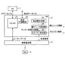
図2は、本実施の形態のゲートウェイ装置(GW2a)の機能構成例を示す図である。図2では、GW2が、アンカーGWとして動作しているときの接続状態を示しているが、図1で2a,2b,2cとして示した、アンカーGW,サービングGW,ターゲットGWは、全て図2と同様の機能構成である。 FIG. 2 is a diagram illustrating a functional configuration example of the gateway device (
図2において、FA/AR(Foreign Agent/Access Router)21は、モバイルIP技術に基づいたFAまたはARである。転送DP(データパス)機能部22は、他のGWとの間に転送パスを設定し、他のGWへの転送パケットの送信と他のGWからの転送パケットの受信を行う。転送量計測部23は、他のGWへ転送しているトラフィック量、転送コネクション数もしくはサービスフロー数、または転送移動端末数などの転送量を計測する。網リソース制御部24は、自局のネットワークリソースおよび近隣のGWのネットワークリソースを取得して保存するとともに、自局のGWのネットワークリソースを管理する。具体的には、上記閾値を超えないように管理する。モビリティ管理部25は、他のGWと連携し、アンカー移動ハンドオフを実行する。 In FIG. 2, FA / AR (Foreign Agent / Access Router) 21 is FA or AR based on mobile IP technology. The transfer DP (data path)
次に、ネットワークリソースの管理とアンカー移動ハンドオフの起動の動作について説明する。以下、図1のGW2a,GW2b,GW2cの各機能構成部とそれぞれの配下の無線基地局は、図2で示した符号にそれぞれa,b,cを追加した符号で表して説明する。 Next, operations of network resource management and anchor movement handoff activation will be described. Hereinafter, the functional components of
まず、MS3は、モバイルIP技術に基づいてFA/AR21aからFA/AR21aの配下のCoAを取得し、HA1にHoAと取得したCoAの対応関係の登録依頼を行い、HA1は受信した情報に基づきHoAとCoAの新たな対応を登録する(位置登録)。これにより、MS3宛のパケットはIPネットワーク6のIPデータパスを経由してFA/AR21aに転送されるようになる。FA/AR21aは、MS3が配下に存在する場合は、データパケットを、無線基地局5aを介してMS3に転送する。 First, the
MS3がGW2bの配下に移動する場合は、まず、アンカーGWであるGW2aの転送DP機能部22aとターゲットGWであるGW2bの転送DP機能部22bとの間で転送データパスが設定され、MS3宛のパケットはGW2bに転送される。次に、ターゲットGWであるGW2bは、サービングGWとして動作を開始し、転送DP機能部22bを介して転送されてきたパケットを、無線基地局5bを介してMS3に転送する。 When the
一方、GW2aでは、転送量計測部23aが、他のGWへの転送量を計測する。ここで、転送量としては、パケット数や転送バイト数などのトラフィック量、転送コネクション数もしくはサービスフロー数、または転送移動端末数などが使用可能である。 On the other hand, in the
網リソース制御部24aは、転送量計測部23aから転送量を取得し、自局のネットワークリソース情報を算出する。ネットワークリソース情報としては、上記の転送量、処理可能な転送量までの余裕量、処理可能な転送量に対する転送量または余裕量の割合、などが使用可能である。また、網リソース制御部24aは、後述するように、近隣のGWのネットワークリソース情報の収集や近隣のGWへのネットワークリソース情報の通知を行う。さらに、網リソース制御部24aは、後述する図3に示すネットワークリソース情報を共有する動作についてのシーケンスにより共有する、自局および近隣GWのネットワークリソース情報を使用して、アンカー移動ハンドオフの起動の必要性を判断し、モビリティ管理部25aに対してアンカー移動ハンドオフの実行を指示する。モビリティ管理部25aは、MS3の無線基地局またはGWをまたがる移動に対応した処理を管理するとともに、アンカー移動ハンドオフを実行する。 The network resource control unit 24a acquires the transfer amount from the transfer amount measurement unit 23a, and calculates the network resource information of the own station. As the network resource information, the above transfer amount, a margin amount up to the processable transfer amount, a transfer amount or a ratio of the margin amount to the processable transfer amount, and the like can be used. Further, as will be described later, the network resource control unit 24a collects network resource information of neighboring GWs and notifies the neighboring GW of network resource information. Further, the network resource control unit 24a needs to start the anchor mobile handoff by using the network resource information of the local station and the neighboring GW shared by the sequence of the operation for sharing the network resource information shown in FIG. The
図3は、網リソース制御部24がネットワークリソース情報を共有する動作についてのシーケンス図である。図3では、GW2dは任意のGW、GW2eはGW2dの近隣に存在するGWである。図3を用いて、網リソース情報の共有手順について説明する。GW2d,GW2eは、図2で示した機能構成とし、図2で示した符号にそれぞれd,eを追加した符号で表して説明する。 FIG. 3 is a sequence diagram of an operation in which the network
まず、GW2dの網リソース制御部24dは、網リソース情報要求31をGW2eの網リソース制御部24eに送信し、ネットワークリソース情報を要求する。これに対してGW2eの網リソース制御部24eは、GW2dの網リソース制御部24dに対して、網リソース情報応答32を返し、ネットワークリソース情報を通知する。このようにして、網リソース制御部24dは、GW2eのネットワークリソース情報を取得する。 First, the network
図4は、網リソース情報要求31に含まれる情報要素の例を示す表である。これらの情報要素は、取得したいネットワークリソース情報の条件を指定するための項目である。報告タイプは要求するネットワークリソース情報のタイプを意味し、転送量の種類(たとえば、パケット数や転送バイト数などのトラフィック量、転送しているコネクション数、サービスフロー数、転送している移動端末など)とネットワークリソース情報の種類(上記の転送量、転送可能量までの余裕量、転送可能量に対する転送量または余裕量の割合など)などを識別する。報告特性は、要求する頻度(1回のみ報告/周期的に報告/指定するイベントで報告)などである。報告イベントは、報告特性で「指定するイベントで報告」を選択した場合のイベントの種類などである。平均時間は、測定値を平均する時間である。報告間隔は、報告特性で「周期的に報告」を選択した場合の報告間隔である。 FIG. 4 is a table showing an example of information elements included in the network
なお、図4は網リソース情報要求31の一例であり、取得したいネットワークリソースの条件を指定できればこの様式でなくてもよい。 Note that FIG. 4 is an example of the network
図5は、網リソース情報応答32に含まれる情報要素の例を示す表である。これらの情報要素は、網リソース情報要求31により指定された条件に基づいて、報告する自装置のネットワークリソース情報を示すものである。報告タイプは、報告するネットワークリソース情報のタイプを示す。報告特性は、網リソース情報要求31で指定された報告特性のうちのどの報告に対応する報告であるのか、また「イベントによる報告」の場合にはどのイベントにより報告するのかを示す。報告値は、網リソース情報要求31で指定された内容に基づいて取得されたネットワークリソース情報を示す。 FIG. 5 is a table showing an example of information elements included in the network
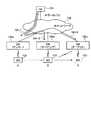
図6は、アンカー移動ハンドオフの必要性の判断に関する網リソース管理処理のフローチャートである。以下、図6を用いて、網リソース制御部24が自局および近隣のGWのネットワークリソース情報をもとにアンカー移動ハンドオフの起動が必要であると判断し、モビリティ管理部25に対してアンカー移動ハンドオフの実行を指示するまでの動作を説明する。 FIG. 6 is a flowchart of a network resource management process related to determination of the necessity of anchor movement handoff. Hereinafter, using FIG. 6, the network
まず、ステップS41において、網リソース制御部24は、前述のように転送量計測部23から転送量を取得し、自局のネットワークリソース情報を算出する。次にステップ42では、ネットワークリソース情報が所定の閾値を越えたかどうかを判断し、越えてない場合は(ステップS42,No)、アンカー移動ハンドオフの実施は必要ないため、網リソース管理処理を終了する。この場合、アンカーGWとしての動作を維持する。越えている場合は(ステップS42,Yes)、アンカー移動ハンドオフを起動し、ステップS43〜S45の手順でアンカーGWの機能を他のGWに移動させる。 First, in step S41, the network
ステップS43では、網リソース制御部24が、アンカー移動ハンドオフのハンドオフ先候補のGW(以下、アンカー移動先候補GWとよぶ)のネットワークリソース情報を取得する。アンカー移動先候補GWは、ひとつでなく複数であってもよい。取得方法としては、前述の図3に示す網リソース情報の取得シーケンスを実行しても良いし、あらかじめ図3に示すシーケンスにより取得して保存しておいたネットワークリソース情報を読み出して使用しても良い。次に、ステップS44では、アンカー移動先候補GWのうち、ネットワークリソースの余裕があるGWをアンカー移動先GWとして選択する。ネットワークリソースの余裕があるGWが複数存在する場合には、たとえば、ネットワークリソースの余裕が最も大きいGWを移動先GWとして選択する。 In step S43, the network
次に、ステップS45で、モビリティ管理部25に対して、選択したGWへのアンカー移動ハンドオフの実行を指示する。 Next, in step S45, the mobility management unit 25 is instructed to execute an anchor movement handoff to the selected GW.
図7は、アンカー移動ハンドオフについて、さらに説明を加えるためのシーケンス図である。このシーケンス図は、図1で示したネットワーク構成例において、データパス4−1でパケットが転送されている状態から図1のデータパス4−4でパケットが転送されている状態に移行する場合のシーケンスを表している。このシーケンス図は、モバイルIPv4技術に基づく場合の例である。 FIG. 7 is a sequence diagram for further explaining the anchor movement handoff. This sequence diagram shows a case where, in the example of the network configuration shown in FIG. 1, the packet is transferred from the data path 4-1 to the state where the packet is transferred from the data path 4-4 in FIG. Represents a sequence. This sequence diagram is an example based on the mobile IPv4 technology.
GW2a,GW2cは、前述のとおり、図2と同様の構成であり、GW2a,GW2cのそれぞれの各構成部には、図2で用いた符号にそれぞれa,cを追加して表す。転送データパス7−1は、アンカーGWであるGW2aからターゲットGWであるGW2cへの転送経路、BS接続パス7−2はGW2cと配下のMS5cとを接続する転送経路、無線パス7−3はMS5cからMS3への無線転送経路である。 As described above, the
次にMS3が移動した後のアンカーハンドオフの動作について説明する。 Next, an anchor handoff operation after the
まず、MS3が図1のAの位置からBの位置に移動すると、MS3宛のパケットは、MS3の移動前のデータパスであるデータパス4−1により、アンカーGWであるGW2aに転送される。その後、MS3宛のパケットは、GW2aの転送DP機能部22aおよびGW2cの転送DP機能部22cによって設定された転送データパス7−1を用いてGW2c(ターゲットGW)に転送される。GW2cは、BS接続パス7−2および無線パス7−3を用いてMS3と接続し、MS3にIPネットワーク6へのアクセスサービスを提供している。 First, when the
次に、アンカーGWであるGW2aの網リソース制御部24aが、前述のように自局および近隣GWのネットワークリソース情報を取得した結果、GW2cへのアンカー移動ハンドオフの起動が必要と判断し、モビリティ管理機能25aに対してアンカー移動ハンドオフの実行を指示したものとする。 Next, as a result of the network resource control unit 24a of the
このとき、モビリティ管理機能25aは、指示されたアンカー移動ハンドオフ先であるGW2cに対して、アンカー移動ハンドオフ要求を送信する(ステップS51)。次に、アンカー移動ハンドオフ要求を受信したGW2cは、MS3にエージェント広告(Agent Advertisement)を送信する(ステップS52)。次に、エージェント広告を受信したMS3は、新しいネットワークに移動したことを認識し、エージェント広告に含まれる情報から新しいCoAを取得する(ステップS53)。 At this time, the
次に、MS3は、HoAとCoAとの関係を対応づける登録要求(Registration Request)をGW2cのFA/AR21cに送信し(ステップS54)、FA/AR21cは登録要求に必要な処理を行い、登録要求をHA1へ転送する(ステップS55)。HA1は、MS3のHoAとCoAとの対応情報(Binding Cache Entry:BCE)を登録(位置登録)し(ステップS56)、MS3にGW2c経由で登録応答(Registration Reply)を送信する(ステップS57,58)。 Next, the
HA1は、MS3に関する新たな位置登録の情報(HoAと新たなCoAとの対応)に基づき、MS3のHoA宛のパケットを、ステップS56で登録されたCoAを宛先として“IP in IPカプセル化”を行い、新IPデータパス4−4を用いて、GW2cに向けて転送を行う。GW2cは、BS接続パス7−2および無線パス7−3を用いて、MS3にパケットを転送し、IPネットワークへのアクセスサービスを提供する。このように、ターゲットGWであったGW2cはアンカーGWとして動作するようになり、GW2aからGW2cへのアンカー移動ハンドオフは完了する。 Based on the new location registration information (correspondence between HoA and new CoA) related to MS3, HA1 performs "IP in IP encapsulation" for packets addressed to HoA of MS3 with the CoA registered in step S56 as the destination. Transfer to the
以上のように、本実施の形態では、アンカーGW2aが、ネットワークリソースが閾値を超えているかどうかを判断し、越えていない場合はアンカーGWとしての動作を維持し、閾値を超えている場合は、ネットワークリソースの閾値を超えていないGW2cにアンカー移動ハンドオフを行うようにした。これにより、GWが制御するサービスエリアを狭くしてもHA1の負荷は大きくならないので、GWのサービスエリアを狭くすることができ、最終的には、GW機能と無線基地局を一体化した新しい構成の装置を実現することができる。また、従来のアンカーGWとしての動作を保持したGWで生じていた、1つのGWに複数の基地局のトラフィックが集中する問題がなくなり、バックホール回線(上位接続回線)でのボトルネックを回避することができる。例えば、GWのバックホール回線に100Mbpsや1Gbpsなどのような限界値がある場合に、通信品質の劣化が生じないように、所定のトラフィック量以下で運用することが可能になる。 As described above, in the present embodiment, the
以上のように、本発明にかかるゲートウェイ装置は、無線ネットワークとIPネットワークを接続する通信システムに有用であり、特に、自装置が接続する通信回線のネットワークリソースに基づいてパケットの転送経路を制御する装置として適している。 As described above, the gateway device according to the present invention is useful for a communication system that connects a wireless network and an IP network, and in particular, controls a packet transfer path based on network resources of a communication line to which the device itself is connected. Suitable as a device.
1,101 HA
2,2a,2b,2c,2d,2e,102a,102b,102c GW
3,103,103a,103b,103c MS(無線移動局)
4−1,4−2,4−3,4−4,104−1,104−2,104−3,105−1,105−2,105−3 データパス
5a,5b,5c 無線基地局
6,106 IPネットワーク
7−1 伝送データパス
7−2 BS接続パス
7−3 無線パス
21,21a,21c FA/AR
22,22a,22b 転送DP機能部
23 転送量計測部
24 網リソース制御部
25,25a モビリティ管理部
31 網リソース情報要求
32 網リソース情報応答1,101 HA
2, 2a, 2b, 2c, 2d, 2e, 102a, 102b, 102c GW
3, 103, 103a, 103b, 103c MS (wireless mobile station)
4-1, 4-2, 4-3, 4-4, 104-1, 104-2, 104-3, 105-1, 105-2, 105-3
22, 22a, 22b Transfer
Claims (8)
Translated fromJapanese自装置が接続する通信回線のネットワークリソースを管理し、ネットワークリソースが予め規定された閾値を超える場合に、移動端末に対するパケットの転送経路を、自装置を経由しない経路に変更することを指示する網リソース制御手段と、
前記網リソース制御手段の指示に基づき、移動端末に対するパケットの転送経路を変更するモビリティ管理手段と、
を備えることを特徴とするゲートウェイ装置。A gateway device for connecting an IP network and a wireless network including a mobile terminal to perform packet transfer,
A network that manages the network resources of the communication line to which the local device is connected, and instructs to change the packet transfer route to the mobile terminal to a route that does not pass through the local device when the network resource exceeds a predetermined threshold. Resource control means;
Based on an instruction from the network resource control means, mobility management means for changing a packet transfer route to the mobile terminal;
A gateway device comprising:
をさらに備えたことを特徴とする請求項1に記載のゲートウェイ装置。A transfer amount measuring means for measuring a transfer amount of a packet between the own device and another gateway device;
The gateway device according to claim 1, further comprising:
をさらに備え、
前記網リソース制御手段を、自装置をアンカーとしている移動端末が自装置の配下から他のゲートウェイ装置の配下へ移動したことを認識した場合に起動し、
前記モビリティ管理手段は、前記選択したゲートウェイ装置に前記移動端末のアンカーとなるよう指示することを特徴とする請求項5または6に記載のゲートウェイ装置。Foreign agent means that operates as a foreign agent (FA) in mobile IP technology,
Further comprising
The network resource control means is activated when it is recognized that a mobile terminal whose anchor is its own device has moved from its own device to another gateway device,
The gateway device according to claim 5 or 6, wherein the mobility management unit instructs the selected gateway device to become an anchor of the mobile terminal.
移動端末のアンカーであるゲートウェイ装置が、自装置のネットワークリソースと他のゲートウェイ装置のネットワークリソース情報を取得するネットワークリソース取得ステップと、
前記ゲートウェイ装置が、自装置のネットワークリソースが予め規定された閾値を超えている場合に、ネットワークリソースが閾値を超えていない他のゲートウェイ装置を選択し、当該選択したゲートウェイ装置に前記移動端末のアンカーとなるよう指示するアンカー変更指示ステップと、
前記選択されたゲートウェイ装置が、前記移動端末にアンカーの移動を知らせる広告を行う広告ステップと、
前記移動端末が、前記広告に基づきアンカーの移動を検知し、前記選択されたゲートウェイ装置から気付けアドレスを取得して新たな位置登録を行う位置登録ステップと、
を含むことを特徴とする通信方法。A communication method using mobile IP technology composed of a wireless network including an IP network and a mobile terminal,
A network resource acquisition step in which the gateway device that is an anchor of the mobile terminal acquires the network resource of its own device and the network resource information of another gateway device;
When the network resource of the own device exceeds a predetermined threshold, the gateway device selects another gateway device whose network resource does not exceed the threshold, and anchors the mobile terminal to the selected gateway device An anchor change instruction step for instructing
An advertising step in which the selected gateway device performs an advertisement informing the mobile terminal of the movement of the anchor;
A location registration step in which the mobile terminal detects a movement of an anchor based on the advertisement, acquires a care-of address from the selected gateway device, and performs a new location registration;
A communication method comprising:
Priority Applications (1)
| Application Number | Priority Date | Filing Date | Title |
|---|---|---|---|
| JP2006254939AJP4890175B2 (en) | 2006-09-20 | 2006-09-20 | Gateway apparatus and communication method |
Applications Claiming Priority (1)
| Application Number | Priority Date | Filing Date | Title |
|---|---|---|---|
| JP2006254939AJP4890175B2 (en) | 2006-09-20 | 2006-09-20 | Gateway apparatus and communication method |
Publications (2)
| Publication Number | Publication Date |
|---|---|
| JP2008078935Atrue JP2008078935A (en) | 2008-04-03 |
| JP4890175B2 JP4890175B2 (en) | 2012-03-07 |
Family
ID=39350539
Family Applications (1)
| Application Number | Title | Priority Date | Filing Date |
|---|---|---|---|
| JP2006254939AExpired - Fee RelatedJP4890175B2 (en) | 2006-09-20 | 2006-09-20 | Gateway apparatus and communication method |
Country Status (1)
| Country | Link |
|---|---|
| JP (1) | JP4890175B2 (en) |
Cited By (9)
| Publication number | Priority date | Publication date | Assignee | Title |
|---|---|---|---|---|
| JP2010166308A (en)* | 2009-01-15 | 2010-07-29 | Japan Radio Co Ltd | WiMAX BASE STATION CONTROL SYSTEM |
| JP2012521130A (en)* | 2009-03-20 | 2012-09-10 | テレフオンアクチーボラゲット エル エム エリクソン(パブル) | Signaling mechanism for network-relay interface with reduced overhead |
| JP2012532566A (en)* | 2009-07-06 | 2012-12-13 | インテル・コーポレーション | Gateway association |
| JP2013503553A (en)* | 2009-08-25 | 2013-01-31 | テレフオンアクチーボラゲット エル エム エリクソン(パブル) | Mobility anchor relocation |
| JP2014530525A (en)* | 2011-09-12 | 2014-11-17 | クゥアルコム・インコーポレイテッドQualcomm Incorporated | Providing communication path information in a hybrid network |
| JP2015159567A (en)* | 2010-03-04 | 2015-09-03 | インターデイジタル パテント ホールディングス インコーポレイテッド | Method and apparatus for identification and transfer in internet protocol multimedia subsystem collaborative sessions |
| US9407507B2 (en) | 2011-08-30 | 2016-08-02 | Qualcomm Incorporated | Topology discovery in a hybrid network |
| US9602555B2 (en) | 2009-11-10 | 2017-03-21 | Interdigital Patent Holdings, Inc. | Collaborative session control transfer and inter-device transfer in internet protocol multimedia subsystem |
| US9674833B2 (en) | 2010-03-18 | 2017-06-06 | Interdigital Patent Holdings, Inc. | Authorizing IUT replication and distinguishing requests for replication from transfers |
Citations (4)
| Publication number | Priority date | Publication date | Assignee | Title |
|---|---|---|---|---|
| JP2004088410A (en)* | 2002-08-27 | 2004-03-18 | Matsushita Electric Ind Co Ltd | Packet communication method |
| JP2005286961A (en)* | 2004-03-31 | 2005-10-13 | Hitachi Communication Technologies Ltd | Cross-connect device, optical cross-connect device, and line relief method using the same |
| JP2006042248A (en)* | 2004-07-30 | 2006-02-09 | Matsushita Electric Ind Co Ltd | Mobile communication method, mobile communication device, and access router device |
| JP2006114946A (en)* | 2004-10-12 | 2006-04-27 | Hitachi Ltd | Mobile network system |
- 2006
- 2006-09-20JPJP2006254939Apatent/JP4890175B2/ennot_activeExpired - Fee Related
Patent Citations (4)
| Publication number | Priority date | Publication date | Assignee | Title |
|---|---|---|---|---|
| JP2004088410A (en)* | 2002-08-27 | 2004-03-18 | Matsushita Electric Ind Co Ltd | Packet communication method |
| JP2005286961A (en)* | 2004-03-31 | 2005-10-13 | Hitachi Communication Technologies Ltd | Cross-connect device, optical cross-connect device, and line relief method using the same |
| JP2006042248A (en)* | 2004-07-30 | 2006-02-09 | Matsushita Electric Ind Co Ltd | Mobile communication method, mobile communication device, and access router device |
| JP2006114946A (en)* | 2004-10-12 | 2006-04-27 | Hitachi Ltd | Mobile network system |
Cited By (12)
| Publication number | Priority date | Publication date | Assignee | Title |
|---|---|---|---|---|
| JP2010166308A (en)* | 2009-01-15 | 2010-07-29 | Japan Radio Co Ltd | WiMAX BASE STATION CONTROL SYSTEM |
| JP2012521130A (en)* | 2009-03-20 | 2012-09-10 | テレフオンアクチーボラゲット エル エム エリクソン(パブル) | Signaling mechanism for network-relay interface with reduced overhead |
| JP2012532566A (en)* | 2009-07-06 | 2012-12-13 | インテル・コーポレーション | Gateway association |
| JP2013503553A (en)* | 2009-08-25 | 2013-01-31 | テレフオンアクチーボラゲット エル エム エリクソン(パブル) | Mobility anchor relocation |
| US9602555B2 (en) | 2009-11-10 | 2017-03-21 | Interdigital Patent Holdings, Inc. | Collaborative session control transfer and inter-device transfer in internet protocol multimedia subsystem |
| US9832236B2 (en) | 2009-11-10 | 2017-11-28 | Interdigital Patent Holdings, Inc. | Collaborative session control transfer and inter-device transfer in internet protocol multimedia subsystem |
| JP2015159567A (en)* | 2010-03-04 | 2015-09-03 | インターデイジタル パテント ホールディングス インコーポレイテッド | Method and apparatus for identification and transfer in internet protocol multimedia subsystem collaborative sessions |
| US9560147B2 (en) | 2010-03-04 | 2017-01-31 | Interdigital Patent Holdings, Inc. | Method and apparatus for identification and transfer in internet protocol multimedia subsystem collaborative sessions |
| US9674833B2 (en) | 2010-03-18 | 2017-06-06 | Interdigital Patent Holdings, Inc. | Authorizing IUT replication and distinguishing requests for replication from transfers |
| US9407507B2 (en) | 2011-08-30 | 2016-08-02 | Qualcomm Incorporated | Topology discovery in a hybrid network |
| JP2014530525A (en)* | 2011-09-12 | 2014-11-17 | クゥアルコム・インコーポレイテッドQualcomm Incorporated | Providing communication path information in a hybrid network |
| US9495326B2 (en) | 2011-09-12 | 2016-11-15 | Qualcomm Incorporated | Providing communication path information in a hybrid communication network |
Also Published As
| Publication number | Publication date |
|---|---|
| JP4890175B2 (en) | 2012-03-07 |
Similar Documents
| Publication | Publication Date | Title |
|---|---|---|
| EP2030468B1 (en) | Changing lte specific anchor with simple tunnel switching | |
| JP4890175B2 (en) | Gateway apparatus and communication method | |
| KR100483007B1 (en) | Method of handover in next generation mobile telecommunication system | |
| JP4848890B2 (en) | Mobile communication system and method, and base station used therefor | |
| US8477729B2 (en) | Support for multi-homing protocols using transient registration and expanded binding revocation messages | |
| Lee et al. | Distributed IP mobility management from the perspective of the IETF: motivations, requirements, approaches, comparison, and challenges | |
| KR100600603B1 (en) | Recording medium storing handover method and method execution program for preventing packet loss in portable internet network | |
| US8169966B2 (en) | Method and a network node for managing handovers in a packet data communication environment | |
| JP4875630B2 (en) | Method for releasing link after handover of multi-mode mobile terminal and mobile terminal | |
| JP2010537528A (en) | How to perform a handover | |
| US20120201222A1 (en) | System and protocols for inter-mobility access gateway tunneling for fast handoff transition | |
| KR100942797B1 (en) | Mobility Management Methods and Mobility Management Anchors, Mobility Nodes | |
| JP6092179B2 (en) | Changing the serving access point for the forward and reverse links | |
| Carmona-Murillo et al. | QoS in Next generation mobile networks: an analytical study | |
| JP5505300B2 (en) | Mobile communication system, movement determination apparatus, mobile terminal, movement management apparatus, mobile terminal route movement method, and program | |
| JP4668097B2 (en) | Mobile terminal apparatus and handover method | |
| LEE et al. | DISTRIBUTED IP MOBILITY MANAGEMENT FROM | |
| CN103516603A (en) | Routing optimization method, device and system | |
| HK1167551A (en) | Mobile communication system, core network node selection method, and base station and mobile station used therefor | |
| HK1167550A (en) | Mobile communication system, core network node selection method, and base station and mobile station used therefor |
Legal Events
| Date | Code | Title | Description |
|---|---|---|---|
| A621 | Written request for application examination | Free format text:JAPANESE INTERMEDIATE CODE: A621 Effective date:20090417 | |
| A977 | Report on retrieval | Free format text:JAPANESE INTERMEDIATE CODE: A971007 Effective date:20110114 | |
| A131 | Notification of reasons for refusal | Free format text:JAPANESE INTERMEDIATE CODE: A131 Effective date:20110208 | |
| A521 | Written amendment | Free format text:JAPANESE INTERMEDIATE CODE: A523 Effective date:20110404 | |
| TRDD | Decision of grant or rejection written | ||
| A01 | Written decision to grant a patent or to grant a registration (utility model) | Free format text:JAPANESE INTERMEDIATE CODE: A01 Effective date:20111213 | |
| A01 | Written decision to grant a patent or to grant a registration (utility model) | Free format text:JAPANESE INTERMEDIATE CODE: A01 | |
| A61 | First payment of annual fees (during grant procedure) | Free format text:JAPANESE INTERMEDIATE CODE: A61 Effective date:20111214 | |
| R150 | Certificate of patent or registration of utility model | Free format text:JAPANESE INTERMEDIATE CODE: R150 | |
| FPAY | Renewal fee payment (event date is renewal date of database) | Free format text:PAYMENT UNTIL: 20141222 Year of fee payment:3 | |
| LAPS | Cancellation because of no payment of annual fees |