JP2008070133A - Vehicle data collecting device - Google Patents
Vehicle data collecting deviceDownload PDFInfo
- Publication number
- JP2008070133A JP2008070133AJP2006246536AJP2006246536AJP2008070133AJP 2008070133 AJP2008070133 AJP 2008070133AJP 2006246536 AJP2006246536 AJP 2006246536AJP 2006246536 AJP2006246536 AJP 2006246536AJP 2008070133 AJP2008070133 AJP 2008070133A
- Authority
- JP
- Japan
- Prior art keywords
- data
- collection
- data collection
- vehicle
- control
- Prior art date
- Legal status (The legal status is an assumption and is not a legal conclusion. Google has not performed a legal analysis and makes no representation as to the accuracy of the status listed.)
- Pending
Links
- 238000013480data collectionMethods0.000claimsabstractdescription133
- 238000004458analytical methodMethods0.000claimsdescription64
- 238000001514detection methodMethods0.000claimsdescription49
- 238000004891communicationMethods0.000abstractdescription13
- 238000012544monitoring processMethods0.000description13
- 230000005856abnormalityEffects0.000description11
- 238000010586diagramMethods0.000description11
- 230000004044responseEffects0.000description8
- 238000000034methodMethods0.000description7
- 230000005540biological transmissionEffects0.000description6
- 238000013500data storageMethods0.000description6
- 238000002485combustion reactionMethods0.000description5
- 230000008569processEffects0.000description5
- 238000003745diagnosisMethods0.000description4
- 238000012545processingMethods0.000description4
- 230000008859changeEffects0.000description3
- 239000000446fuelSubstances0.000description3
- 238000002360preparation methodMethods0.000description3
- 238000012423maintenanceMethods0.000description2
- 238000005070samplingMethods0.000description2
- 230000007704transitionEffects0.000description2
- XLYOFNOQVPJJNP-UHFFFAOYSA-NwaterSubstancesOXLYOFNOQVPJJNP-UHFFFAOYSA-N0.000description2
- 238000007405data analysisMethods0.000description1
- 230000003111delayed effectEffects0.000description1
- 238000011161developmentMethods0.000description1
- 238000005516engineering processMethods0.000description1
- 230000006870functionEffects0.000description1
- 230000010365information processingEffects0.000description1
- 238000002347injectionMethods0.000description1
- 239000007924injectionSubstances0.000description1
- 238000007726management methodMethods0.000description1
- 230000002093peripheral effectEffects0.000description1
- 230000008439repair processEffects0.000description1
- 239000007858starting materialSubstances0.000description1
- 238000012360testing methodMethods0.000description1
- 230000001052transient effectEffects0.000description1
- 238000012795verificationMethods0.000description1
Images


Landscapes
- Small-Scale Networks (AREA)
Abstract
Description
Translated fromJapanese本発明は、車両側の電子制御装置(ECU)から各種の制御データを収集し、パーソナルコンピュータや分析装置などの解析側の装置へ適宜出力するデータ・ロガーなどと称される車両データ収集装置に関する。 The present invention relates to a vehicle data collection device called a data logger that collects various control data from an electronic control unit (ECU) on a vehicle side and appropriately outputs it to an analysis side device such as a personal computer or an analysis device. .
車両の開発後期での動作検証、実際の市場投入後の走行データ収集、不具合原因解明の等のデータ収集などのために、前記の車両データ収集装置が、適宜車両に搭載されてデータの収集が行われている。一方、車両の側では電子制御化が進み、多くのセンサが搭載されて、その検出結果がマイクロコンピュータやその周辺回路などで構成される前記電子制御装置(ECU)に取込まれ、その検出結果に対応して各種のアクチュエータが制御されることによって、運転者の煩雑な操作が不要になったり、燃費が向上するなどの高機能化が図られている。また、前記燃費の向上や排ガスの管理などのために、前記電子制御装置(ECU)の搭載が法的に義務付けられつつある。 The vehicle data collection device is installed in the vehicle as needed for data collection such as vehicle operation verification in the later stages of vehicle development, actual travel data collection after market entry, and failure cause elucidation. Has been done. On the other hand, electronic control advances on the vehicle side, many sensors are mounted, and the detection results are taken into the electronic control unit (ECU) composed of a microcomputer and its peripheral circuits, and the detection results By controlling the various actuators in response to the above, high functionality is achieved such that the driver's troublesome operation becomes unnecessary and fuel consumption is improved. In addition, the electronic control unit (ECU) is being legally obliged to improve the fuel consumption and exhaust gas management.
したがって、特殊なパラメータでない限り、新たなセンサなどを設けることなく、電子制御装置(ECU)内に格納されているデータを読出すことで所望とする制御データを得て、前記車両データ収集装置に格納してゆくことができる。しかも、多機能化に伴い前記電子制御装置(ECU)の台数が増加の傾向にあり、また高機能化に伴いやり取りされるデータ量が増加し、効率的に伝送するために、CANを代表とする車内LANなどの車両内ネットワークが導入されるようになっている。このため、前記車両データ収集装置をこの車両内ネットワークに接続するだけで、所望とする種類のデータを容易に入手できるようになる。 Therefore, unless it is a special parameter, the desired control data is obtained by reading the data stored in the electronic control unit (ECU) without providing a new sensor, and the vehicle data collecting device It can be stored. In addition, the number of electronic control units (ECUs) tends to increase with increasing functionality, and the amount of data exchanged with increasing functionality increases, so that CAN can be transmitted efficiently. In-vehicle networks such as in-vehicle LANs have been introduced. For this reason, it becomes possible to easily obtain the desired type of data simply by connecting the vehicle data collection device to the in-vehicle network.
そこで、特許文献1には、ECUがセンサ出力を信号処理して時刻データを付加して車両内ネットワークへ送信し、それを外部診断装置が取込み、イグニションONのタイミングを基準時刻(t0)として、別途に設けたセンサ出力とともに、データ・ロガーに記録してゆくことで、ECU経由のデータとセンサから直接のデータとを時系列に並べて表示でき、ECUの動作・機能を的確に調査できるようにした車両用補機診断システムが提案されている。
上述の従来技術では、イグニションONのタイミングを合わせることができるけれども、どのタイミングからデータを収集するのかが明確でない。また、上述の従来技術は、センサを増設し、信号線を引回したり、外部診断装置を設置するなど、ベンチテストのような状況で使用されるものと推定される。したがって、このような状況では、作業者がデータの収集開始/停止を操作すればよいが、上述のように車両データ収集装置を実際に車両に搭載して、長期に亘ってデータの収集を行う場合、前部座席の下やトランクなどに搭載される該車両データ収集装置は操作し難く、また操作を忘れる可能性も高く、適切なデータを取得できない可能性がある。 In the above-described prior art, the ignition ON timing can be adjusted, but it is not clear from which timing data is collected. In addition, it is estimated that the above-described conventional technology is used in a situation such as a bench test, such as adding sensors, routing signal lines, or installing an external diagnostic device. Therefore, in such a situation, the operator may operate data collection start / stop. However, as described above, the vehicle data collection device is actually mounted on the vehicle, and data is collected over a long period of time. In this case, the vehicle data collection device mounted under the front seat or on the trunk is difficult to operate, and there is a high possibility that the operation will be forgotten, and there is a possibility that appropriate data cannot be acquired.
本発明の目的は、適切にデータを取得することができる車両データ収集装置を提供することである。 An object of the present invention is to provide a vehicle data collection device that can appropriately acquire data.
本発明の車両データ収集装置は、収集手段が車両側の電子制御装置から制御データを収集し、解析側の装置へ出力する車両データ収集装置において、原動機の駆動回路への電源供給の有無を検出する第1の検出手段と、前記解析側の装置が能動状態にあるか否かを検出する第2の検出手段と、前記第1および第2の検出手段による検出結果および検出タイミングに基づいて、前記収集手段に、制御データの収集の開始、終了または継続、もしくは収集した制御データの出力の少なくとも1つを行わせる収集制御手段とを含むことを特徴とする。 The vehicle data collection device of the present invention detects whether power is supplied to the drive circuit of the prime mover in the vehicle data collection device in which the collecting means collects control data from the electronic control device on the vehicle side and outputs it to the analysis side device. Based on detection results and detection timing by the first detection means, the second detection means for detecting whether or not the analysis side device is in an active state, and the first and second detection means, Collecting control means for causing the collecting means to start, end or continue collecting control data, or to output at least one of the collected control data.
上記の構成によれば、収集手段が車両側の電子制御装置(ECU)から各種の制御データを収集し、パーソナルコンピュータや分析装置などの解析側の装置へ適宜出力するデータ・ロガーなどと称される車両データ収集装置において、少なくとも2つの検出手段およびその検出結果に応答して前記制御データの収集を行うか否か、もしくは出力を行うか否かを制御する収集制御手段を設け、第1の検出手段は原動機の駆動回路、たとえばイグニションキースイッチの操作による内燃機関の点火回路への電源供給の有無を検出し、第2の検出手段は前記解析側の装置が能動状態にあるか否かを、たとえばUSBによる電源供給の有無から検出し、収集制御手段は、前記第1および第2の検出手段による検出結果および検出タイミング(シーケンス)に基づいて、前記収集手段に、制御データの収集の開始、終了または継続、もしくは収集した制御データの出力の少なくとも1つを行わせる。 According to the above configuration, the collecting means collects various control data from the electronic control unit (ECU) on the vehicle side, and is referred to as a data logger or the like that is appropriately output to an analysis side device such as a personal computer or an analysis device. In the vehicle data collection device, there is provided at least two detection means and collection control means for controlling whether or not to collect the control data in response to the detection result or whether or not to output the control data. The detecting means detects the presence or absence of power supply to the engine driving circuit, for example, the ignition circuit of the internal combustion engine by operating the ignition key switch, and the second detecting means determines whether or not the analysis side device is in an active state. For example, it is detected from the presence or absence of power supply by USB, and the collection control means detects the detection result and detection timing (sequential ) On the basis, on the collection means, the control start of the collection of data, termination or continuation, or at least one of causes of output of the collected control data.
たとえば、第1の検出手段によって駆動回路へ電源供給が開始されたことを検出し、第2の検出手段によって解析側の装置が非能動状態(接続されていないか、電源が入っていない)であることを検出すると、解析側の装置へデータを送信する必要はなく、該車両データ収集装置は単体でデータ収集を開始する。同様に、解析側の装置が能動状態に無い状態で、駆動回路への電源供給が停止されると、直後に或いは予め定める時間が経過した後に、そのデータ収集を終了する。 For example, it is detected that power supply to the drive circuit is started by the first detection means, and the analysis-side device is in an inactive state (not connected or not turned on) by the second detection means. When it is detected, there is no need to transmit data to the analysis side device, and the vehicle data collection device starts collecting data by itself. Similarly, when the power supply to the drive circuit is stopped in a state where the analysis-side apparatus is not in an active state, the data collection is terminated immediately or after a predetermined time has elapsed.
また、駆動回路へ電源供給が行われていない状態で、解析側の装置が能動状態になったことを検出すると、データを収集する必要はなく、解析側の装置と連携状態となり、該車両データ収集装置は収集したデータを出力可能となる。 In addition, when it is detected that the analysis side device is in an active state in a state where power is not supplied to the drive circuit, it is not necessary to collect data, and the vehicle data is linked to the analysis side device. The collecting device can output the collected data.
さらにまた、駆動回路へ電源供給が開始された後、解析側の装置が能動状態になった場合には、先ず駆動回路へ電源供給が開始された時点でデータ収集を開始しており、解析側の装置が能動状態になってもデータ収集を継続し、解析側の装置からデータ収集を終了すべき信号が入力された時点でデータ収集を終了することで、たとえば或る程度走行してデータを収集した後、走行は継続しても任意のタイミングで収集を終了することができる。これに対して、解析側の装置が能動状態になっている状態で、駆動回路へ電源供給が開始された場合には、解析の準備が整ってからデータの収集を開始するものと判定し、解析側の装置からデータ収集を開始すべき信号が入力されるまでデータ収集を開始しないことで、たとえば或る程度走行した後、任意のタイミングからのデータ収集を開始することができる。 Furthermore, after the power supply to the drive circuit is started, if the analysis side device becomes active, data collection is started when power supply to the drive circuit is started first. Data collection is continued even when the device becomes active, and data collection is terminated when a signal to terminate data collection is input from the analysis side device. After the collection, the collection can be terminated at an arbitrary timing even if the running is continued. On the other hand, if power supply to the drive circuit is started while the analysis side device is in an active state, it is determined that data collection starts after preparation for analysis is completed, By not starting data collection until a signal to start data collection is input from the analysis side device, for example, after traveling to some extent, data collection from an arbitrary timing can be started.
また、駆動回路へ電源供給が行われている状態で、解析側の装置が非能動状態になったことを検出すると(切離されたか、電源が切られた状態)、データ出力等の解析側の装置との連携は終了しても、収集は継続する。 In addition, if it is detected that the analysis side device is in an inactive state while power is being supplied to the drive circuit (disconnected or powered off), the analysis side for data output, etc. The collection continues even if the cooperation with the device is terminated.
さらにまた、解析側の装置が能動状態のままで、駆動回路への電源供給が停止すると、データ収集を停止しても、該車両データ収集装置は停止せず、解析側の装置からの送信の要求などに応える連携状態とする。 Furthermore, when the power supply to the drive circuit is stopped while the analysis side device remains in the active state, even if the data collection is stopped, the vehicle data collection device does not stop and the transmission from the analysis side device is not performed. A linked state that responds to requests and the like.
したがって、データ収集や収集したデータの出力を自動で適切に行うことができ、作業者の操作が不要になって利便性を向上することができる。また、車両不使用時などでの無駄なデータを収集しなくでき、収集したデータの記録媒体を小型化することができ、或いは収集期間を延ばすことができる。 Therefore, data collection and output of the collected data can be performed automatically and appropriately, and the operator's operation becomes unnecessary, and convenience can be improved. Further, it is possible to avoid collecting useless data when the vehicle is not used and the like, the recording medium for the collected data can be reduced in size, or the collection period can be extended.
さらにまた、本発明の車両データ収集装置では、前記収集手段は、車両内ネットワークで伝送される前記制御データを収集し、前記収集手段に収集すべき制御データの識別情報を設定する設定手段と、前記設定手段が設定すべき識別情報を、車種毎に予めグループ化して格納しているテーブルとをさらに備えることを特徴とする。 Furthermore, in the vehicle data collection device of the present invention, the collection means collects the control data transmitted through the in-vehicle network, and sets setting information identifying control data to be collected in the collection means; The information processing apparatus further includes a table that stores the identification information to be set by the setting unit in advance for each vehicle type.
上記の構成によれば、前記収集手段は、車内LANなどの車両内ネットワークを介して、電子制御装置とセンサやアクチュエータとの間、或いは電子制御装置間で伝送される種々の制御データの内、予め設定手段で設定された必要なデータだけを前記電子制御装置に要求して収集してゆくにあたって、収集すべき制御データの識別情報(前記電子制御装置のメモリ領域におけるアドレス)を車種毎に予めグループ化して格納しているテーブルを設け、設定手段に前記車種を入力するだけで、設定手段はそのテーブルから必要な識別情報を取得し、前記収集手段に(読出しアドレスを)設定する。 According to the above-described configuration, the collection means includes various control data transmitted between the electronic control device and the sensor or actuator, or between the electronic control devices, via an in-vehicle network such as an in-vehicle LAN. In requesting and collecting only the necessary data set in advance by the setting means from the electronic control unit, identification information (address in the memory area of the electronic control unit) of the control data to be collected is previously stored for each vehicle type. A table stored in a group is provided, and the setting means acquires necessary identification information from the table just by inputting the vehicle type to the setting means, and sets (reading address) in the collecting means.
したがって、共通の車両データ収集装置を、簡単な選択操作で異なる車種に使用可能とすることができる。なお、好ましくはサンプリング周期も併せて設定可能とすることで、比較的変化の少ない水温等のデータを間引くなど、記録媒体の記録容量や収集期間などに応じた効率の良いデータ収集を行うことができる。 Therefore, the common vehicle data collection device can be used for different vehicle types by a simple selection operation. Preferably, the sampling cycle can also be set, so that efficient data collection can be performed according to the recording capacity of the recording medium, the collection period, etc. it can.
また、本発明の車両データ収集装置では、前記収集手段は、車両内ネットワークを介して前記電子制御装置から制御データを収集しつつ、その制御データをモニタしており、前記第1の検出手段によって駆動回路への電源供給が検出されている間に前記制御データが受信されなくなると、予め定める時間に亘る待機と前記電子制御装置へのセキュリティ解除の要求とを交互に繰返し行うことを特徴とする。 In the vehicle data collection device of the present invention, the collection unit collects control data from the electronic control unit via a vehicle network and monitors the control data, and the first detection unit When the control data is not received while the power supply to the drive circuit is detected, a standby for a predetermined time and a request for releasing the security to the electronic control device are alternately repeated. .
上記の構成によれば、前記収集手段がCANなどの車両内ネットワークを介して前記電子制御装置から制御データを収集する場合、制御データのモニタによって該車両データ収集装置と前記電子制御装置との通信が一旦途絶したことが検出されても、前記第1の検出手段によって駆動回路への電源供給が検出されていると、該車両データ収集装置は制御データの収集動作を終了するのではなく、休止状態とし、予め定める時間、たとえば5秒間だけ待機した後、前記電子制御装置へ前記車両内ネットワークの規格によって制御データの通信のために必要となるセキュリティ解除の要求を行い、解除できなかった場合には再び前記予め定める時間の待機とセキュリティ解除の要求とを繰返し行う。 According to said structure, when the said collection means collects control data from the said electronic control apparatus via in-vehicle networks, such as CAN, communication between this vehicle data collection apparatus and the said electronic control apparatus by control data monitoring Even if it is detected that the vehicle has been interrupted, if the power supply to the drive circuit is detected by the first detection means, the vehicle data collection device does not end the control data collection operation but pauses. After waiting for a predetermined time, for example, 5 seconds, and making a request for releasing the security required for communication of control data to the electronic control device according to the standard of the in-vehicle network, the state cannot be released Repeats the waiting for the predetermined time and the security release request again.
したがって、振動などによるコネクタ部分の接触不良など、一過性の制御データの伝送不良に対して、データの収集を継続して行うことができる。 Therefore, it is possible to continuously collect data for transient control data transmission failure such as contact failure of the connector portion due to vibration or the like.
さらにまた、本発明の車両データ収集装置では、前記収集手段は、前記電子制御装置から複数種類の制御データを、予め定める周期内で、その制御データに予め定められた順で受信し、受信できなかった制御データに関しては、前記予め定める周期内で受信されるまで繰返し再送要求を送信することを特徴とする。 Furthermore, in the vehicle data collection device of the present invention, the collection means can receive and receive a plurality of types of control data from the electronic control device in a predetermined order in the control data within a predetermined cycle. With respect to the control data that has not been received, a retransmission request is repeatedly transmitted until it is received within the predetermined period.
上記の構成によれば、前記収集手段は、前記電子制御装置から複数種類の制御データを受信するにあたって、その制御データに順位を与えて、予め定める周期毎に受信動作を行ってゆく。その際、受信できなかった制御データに関しては、受信されるまで繰返し再送要求を送信するが、その再送要求は前記予め定める周期を過ぎたら行わず、次の周期ではまた上位の制御データから送信を要求する。 According to the above configuration, when receiving a plurality of types of control data from the electronic control device, the collecting unit gives a ranking to the control data and performs a receiving operation at predetermined intervals. At that time, for the control data that could not be received, a retransmission request is repeatedly transmitted until it is received, but the retransmission request is not made after the predetermined period, and transmission is performed from the higher-level control data in the next period. Request.
したがって、順位(重要度)の低い制御データの脱落を防止するあまり、順位(重要度)の高い制御データに脱落が生じてしまうような不具合を無くすことができる。 Therefore, it is possible to eliminate such a problem that the control data having a high order (importance) is dropped, so as to prevent the control data having a low order (importance) from being dropped.
本発明の車両データ収集装置は、以上のように、収集手段が車両側の電子制御装置(ECU)から各種の制御データを収集し、パーソナルコンピュータや分析装置などの解析側の装置へ適宜出力するデータ・ロガーなどと称される車両データ収集装置において、少なくとも2つの検出手段およびその検出結果に応答して前記制御データの収集を行うか否か、もしくは出力を行うか否かを制御する収集制御手段を設け、第1の検出手段は原動機の駆動回路、たとえばイグニションキースイッチの操作による内燃機関の点火回路への電源供給の有無を検出し、第2の検出手段は前記解析側の装置が能動状態にあるか否かを、たとえばUSBによる電源供給の有無から検出し、収集制御手段は、前記第1および第2の検出手段による検出結果および検出タイミング(シーケンス)に基づいて、前記収集手段に、制御データの収集の開始、終了または継続、もしくは収集した制御データの出力の少なくとも1つを行わせる。 As described above, in the vehicle data collection device of the present invention, the collection unit collects various control data from the vehicle-side electronic control unit (ECU), and appropriately outputs it to an analysis-side device such as a personal computer or an analysis device. In a vehicle data collection device called a data logger or the like, collection control for controlling whether or not to collect the control data or output in response to at least two detection means and the detection result Means for detecting the presence or absence of power supply to the engine driving circuit, for example, the ignition circuit of the internal combustion engine by operating the ignition key switch, and the second detecting means is activated by the analysis side device. For example, from the presence or absence of power supply by USB, the collection control means detects the detection results by the first and second detection means and Out based on the timing (sequence), to said collecting means, controlling start of data collection, termination or continuation, or at least one of causes of output of the collected control data.
それゆえ、データ収集や収集したデータの出力を自動で適切に行うことができ、作業者の操作が不要になって利便性を向上することができる。また、車両不使用時などでの無駄なデータを収集しなくでき、収集したデータの記録媒体を小型化することができ、或いは収集期間を延ばすことができる。 Therefore, data collection and output of the collected data can be performed automatically and appropriately, and the operator's operation becomes unnecessary, and convenience can be improved. Further, it is possible to avoid collecting useless data when the vehicle is not used and the like, the recording medium for the collected data can be reduced in size, or the collection period can be extended.
[実施の形態1]
図1および図2は、本発明の実施の一形態に係る車両データ収集装置1の使用状態を説明するための図である。この車両データ収集装置1は、車両3の前部座席の下やトランクなどに搭載され、図1で示すように第1のコネクタ11にハーネス21が接続されることで、車両3側の車内LAN31を介して複数のECU32,33,34から各種の制御データの収集が可能になる。また、この車両データ収集装置1は、机上において、或いは車両3に搭載したまま、図2で示すように第2のコネクタ12にハーネス22が接続されることで、収集した制御データをパーソナルコンピュータや分析装置などの解析装置4へ適宜出力することが可能になる。[Embodiment 1]
1 and 2 are diagrams for explaining a use state of the vehicle
前記ハーネス21は、前記車内LAN31において、ディーラー等での故障診断やメンテナンスなどのために設けられているダイアグコネクタに接続されるにハーネス23に、イグニションキースイッチのON接点と接続されるIG検知用ケーブル24を備えて構成される。ダイアグコネクタには、車内LAN31用の2本の端子と、+B接点に接続される2本の電源端子とが備えられている。前記ハーネス22は、USBケーブルから成る。 In the in-
図3は、前記車両データ収集装置1の電気的構成を示すブロック図である。イグニションキースイッチ51には、バッテリ52からの電圧+Bが供給されており、Acc接点が導通されるとオーディオやパワーウインドゥなどのアクセサリや補機が使用可能となり、ON接点が導通されると内燃機関の点火回路に給電されて該内燃機関の回転が可能になり、ST接点が導通されるとスターターモータが起動して前記内燃機関の始動が可能になる。 FIG. 3 is a block diagram showing an electrical configuration of the vehicle
このイグニションキースイッチ51において、ON接点に導通されているか否かは、前記IG検知用ケーブル24を介して、前記電源部13が検知することができる。また、バッテリ52からの電圧+Bが印加されているか否か、すなわち前記ダイアグコネクタが接続されているか否かは、前記ハーネス21内の+B検知用ケーブル25を介して、電源部13が検知することができる。電源部13は、データ収集時に、この+B検知用ケーブル25を介する+B電圧によって、該車両データ収集装置1内の各回路に電源供給を行う。 In the ignition
前記電源部13はまた、車内LAN31や解析装置4のUSB電源から、相手側装置(前記ECU32,33,34や解析装置4)が能動状態にあるか否かを検出することができるとともに、該電源部13は、解析装置4へのデータ出力時に、このUSB電源によって該車両データ収集装置1内の各回路に電源供給を行う。 The
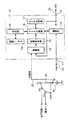
図4は、前記電源部13の具体的構成を示すブロック図である。前記バッテリ52の+B電圧は、前記+B検知用ケーブル25から通常ONのリレー131を介して電源回路132に供給され、電源回路132は、DC12V等の前記+B電圧を、5V等の予め定める内部の電源電圧に降圧および安定化させて該車両データ収集装置1内の各回路に電源供給を行う。前記リレー131は、後述するようにデータ収集を終了すべきときに遮断され、これによって前記各回路への電源供給が遮断される。一方、前記イグニションキースイッチ51のON接点は、前記IG検知用ケーブル24からダイオード133を介して前記電源回路132に接続されるとともに、そのON接点からIG電圧(+B)が供給されているか否かが、電圧監視回路134によって検出される。 FIG. 4 is a block diagram showing a specific configuration of the
同様に、解析装置4のUSB電源は、前記ハーネス22からダイオード135を介して、前記電源回路132の出力側に接続され、そのまま各回路に電源供給を行うことができるとともに、USB電源電圧が供給されているか否かが、電圧監視回路136によって検出される。したがって、前記電圧監視回路134は、原動機(内燃機関)の駆動回路(点火回路)への電源供給の有無を検出する第1の検出手段となり、前記電圧監視回路136は、解析装置4が能動状態にあるか否かを検出する第2の検出手段となる。 Similarly, the USB power supply of the analysis device 4 is connected to the output side of the
前記電源部13の電圧監視回路134,136での検出結果は、収集制御手段である収集制御部14に入力され、その検出結果に対応して収集制御部14は、収集手段であるデータ収集部15でのデータ収集および出力を、後述するような態様で制御する。データ収集部15は、前記USB規格などに対応した通信部16を介してECU32,33,34から収集した制御データを、不揮発性のデータ記憶部17へ格納し、また格納していた制御データを前記通信部16を介して解析装置4へ出力する。前記データ記憶部17は、メモリカードなどで実現され、解析装置4は、収集された制御データの解析を行うにあたって、必ずしもハーネス22を介してデータの取込みを行わなくてもよく、着脱式の前記メモリカードを車両データ収集装置1から取外し、該解析装置4にそのまま装着して取込むようにしてもよい。 The detection results in the
前記ECU32,33,34で取扱われる制御データの内、どの制御データを選択して収集するかは、設定手段である設定部18によって予めデータ収集部15に設定されている。その設定部18は、入力操作部(図3では図示を省略している)を有し、またこの設定部18での設定作業のために、予め機種テーブル19が用意されている。そして、作業者がこの設定部18の前記入力操作部から該車両データ収集装置1の搭載車種を入力すると、前記機種テーブル19に予めグループ化して格納されている収集すべき制御データの種類(パラメータID)、その制御データが格納されているECU32,33,34のメモリ領域におけるアドレス、その制御データのサイズ、データ位置、データ型式、解像度、オフセット値、最大・最小値、名称、単位、およびその制御データを要求するにあたってのセキュリティ解除の方法などが、設定部18に読出され、前記データ収集部15に設定される。 Of the control data handled by the
前記機種テーブル19は、解析装置4等の外部のパーソナルコンピュータなどにおいて、新型式の登場や、仕様の変更などに対応して適宜編集・作成され、必要なものだけが設定部18によってダウンロードされ、データ収集部15に設定されるようにしてもよい。 The model table 19 is appropriately edited and created in response to the appearance of a new model, a change in specifications, etc. in an external personal computer such as the analysis apparatus 4, and only necessary items are downloaded by the setting
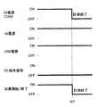
図5〜図11は、上述のように構成される車両データ収集装置1の収集制御部14の動作を説明するためのタイミングチャートである。先ず、該車両データ収集装置1が車両3に搭載され、図5で示すように、USB電源がOFFの解析装置4が非能動状態(接続されていないか電源が入っていない状態)では、前記解析装置4へは制御データを出力する必要はなく、また前記解析装置4からは何らの信号も入力されない。したがって、ダイアグコネクタが接続されて+B電圧が供給されている状態で、エンジン始動されてON接点に繋がり、その時刻t1においてIG電圧が立ち上がると、車両3が直ぐにでも走り出せる状態であるので、これに応答して前記収集制御部14は、データ収集部15に単体で制御データの収集を開始させる。 FIGS. 5-11 is a timing chart for demonstrating operation | movement of the
同様に、解析装置4が能動状態に無い状態で、図6で示すようにイグニションキースイッチ51がAcc接点またはOFF接点に戻されると、エンジン回転は停止され、その時刻t2において、IG電圧が立ち下がり、これに応答して前記収集制御部14は、データ収集部15に収集させた制御データを前記不揮発性のデータ記憶部17に記憶させた後、前記リレー131を遮断し、制御データの収集を終了させる。しかしながら、ECUによっては、IGOFF後にも暫く動作し続けるものもあり、それに対応して、予め定める時間が経過した時刻t3においてデータ収集を終了するようにしてもよい。 Similarly, when the ignition
また、IGOFFで解析装置4が能動状態になると、データを収集する必要はないが、解析装置4へデータを送信する必要が生じる可能性があり、図7で示すように前記解析装置4からのUSB電源が立上がると、収集制御部14も立上がり、その時刻t11から解析装置4と連携状態となる。この状態で、解析装置4からのコマンドがあればそれに応答し、収集した制御データを解析装置4へ送信する。またこの立上がり時に、システム修復作業等のメンテナンス作業を行った後、解析装置4と連携状態となるようにしてもよい。このIGOFF状態は、エンジン停止している状態、または該車両データ収集装置1が車両3から取外されている状態であるので、+B電圧は、ON(ダイアグコネクタが接続される)でもOFFでも問題ない(図7ではONで示している)。 Further, when the analysis device 4 becomes active due to IGOFF, there is no need to collect data, but there is a possibility that data needs to be transmitted to the analysis device 4, and as shown in FIG. When the USB power supply is started up, the
さらにまた、イグニションキースイッチ51がON状態となった後、解析装置4が能動状態になった場合には、図8で示すように、前記収集制御部14は、先ずデータ収集部15に、IGONとなった時刻t21でデータ収集を開始させており、解析装置4が時刻t22で能動状態になってもデータ収集を継続させ、解析装置4からデータ収集を終了すべき信号が入力された時刻t23でデータ収集を終了させる。こうして、たとえば或る程度走行してデータを収集した後、走行は継続しても、解析装置4を立上げ、任意のタイミングで収集を終了することができる。また、コネクタが外れたり、解析装置4の電源が切れても、IGONの状態が継続する限り、データの収集が継続される。 Furthermore, when the analysis device 4 becomes active after the ignition
これに対して、解析装置4が能動状態になっている状態で、イグニションキースイッチ51がONとなると、前記収集制御部14は、解析の準備が整ってからデータの収集を開始するものと判定し、図9で示すように、時刻t31でUSB電源が立上がり、時刻t32でIGONとなってもデータ収集は行わず、時刻t33で解析装置4からデータ収集を開始すべき信号が入力されてからデータ収集を開始する。こうして、たとえば或る程度走行した後、任意のタイミングからデータ収集を開始することができる。 On the other hand, when the ignition
また、イグニションキースイッチ51がON状態で、解析装置4が非能動状態(切離されたか、電源が切られた状態)になったことを検出すると、図10で示すように、前記収集制御部14は、その時刻t41で解析装置4へのデータ出力等の解析装置4との連携は終了しても、データの収集は継続する。 Further, when it is detected that the ignition
さらにまた、解析装置4が能動状態のままで、イグニションキースイッチ51がON状態から切換えられると、図11で示すように、前記収集制御部14は、その時刻t51でデータ収集を停止しても、少なくともUSB電源は供給されているので、停止はせず、解析装置4からの送信の要求などに応える。 Furthermore, when the ignition
このように収集制御部14が、電圧監視回路134によって検出されるIG電圧および電圧監視回路136によって検出されるUSB電圧の検出結果および検出タイミング(シーケンス)に基づいて、データ収集部15に、各ECU32,33,34からの制御データの収集の開始、終了または継続、もしくは収集した制御データの解析装置4への出力の内の少なくとも1つを行わせることで、データ収集や収集したデータの出力を自動で適切に行うことができ、作業者の操作が不要になって利便性を向上することができる。また、車両3の不使用時などでの無駄なデータを収集しなくでき、データ記憶部17を小型化することができ、或いは収集期間を延ばすことができる。 In this way, the
また、前記データ収集部15が車内LAN31で伝送される制御データの内から、予め設定部18で設定された必要なデータだけをECU32,33,34に要求して収集してゆくにあたって、収集すべき制御データのアドレスを車種毎に予めグループ化して格納している機種テーブル19を設け、設定部18に前記車種を入力するだけで、設定部18はその機種テーブル19から必要なアドレスを取得し、前記データ収集部15に読出してアドレスを設定するので、共通の車両データ収集装置1を、簡単な選択操作で異なる車種に使用可能とすることができる。なお、好ましくはサンプリング周期も併せて設定可能とすることで、比較的変化の少ない水温等のデータを間引くなど、データ記憶部17の記憶容量や収集期間などに応じた効率の良いデータ収集を行うことができる。 Further, when the
ここで、上述のような車両データ収集装置1は、長期間に亘ってデータの収集・記録を行うので、コネクタが外れたり、振動等で一時的に接触不良が生じるなどの機械的な異常や、ECU32,33,34の処理が重くなり、データの返信を行えなくなるなどの電気的な異常によって、データ収集が行えなくなる可能性がある。 Here, since the vehicle
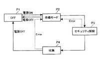
そこで前記データ収集部15は、通信部16での通信状態をモニタし、その結果から、先ず前記機械的な異常に対しては、図12で示すような状態遷移を行う。すなわち、ステップP1からP2で示すようにIG電源がONとなると待機モードとなり、その後ステップP3で示すように、CANなどの前記車内LAN31で規格化されているセキュリティ解除動作を行う。このセキュリティ解除の方法は、前記のように設定部18によって機種テーブル19から読出され、データ収集部15に設定されている。 Therefore, the
そのセキュリティ解除に成功すると、ステップP4で制御データの収集が行われ、異常が生じないか、IG電源がOFFとならない限りはこのステップP4に留まり、制御データの収集が継続して行われる。これに対して、前記ステップP3でセキュリティ解除に失敗すると、再びステップP2の待機モードに戻り、予め定める時間、たとえば5秒間待機し、再びステップP3のセキュリティ解除動作を行う。これは、ECU32,33,34が、一旦セキュリティ解除に失敗すると所定時間を開けないと解除動作に応答しないためであり、こうしてセキュリティ解除に成功するまで、ステップP2,P3を繰返す。 If the security release is successful, control data is collected in step P4. Unless an abnormality occurs or the IG power supply is not turned off, the control data is collected and control data is continuously collected. On the other hand, if the security release fails in step P3, the process returns to the standby mode of step P2 again, waits for a predetermined time, for example, 5 seconds, and performs the security release operation of step P3 again. This is because the
一方、前記ステップP4での制御データの収集中に、前記のような異常が生じると、前記ステップP2の待機モードに戻り、待機の後、ステップP3のセキュリティ解除動作に成功するとステップP4の制御データの収集動作に復帰する。これに対して、異常が生じたままであるときには前記ステップP2,P3を繰返し、異常が解消し、セキュリティ解除動作に成功するとステップP4の制御データの収集動作に復帰する。また、ステップP4でIG電源がOFFとなったとき、およびステップP2でIG電源がOFFとなったときは前記ステップP1に戻り、再びIG電源がONとなるまで待機する。 On the other hand, if an abnormality such as described above occurs during the collection of control data in step P4, the process returns to the standby mode in step P2, and after the standby, if the security release operation in step P3 is successful, the control data in step P4. Return to the collection operation. On the other hand, when the abnormality remains, the steps P2 and P3 are repeated, the abnormality is resolved, and when the security release operation is successful, the process returns to the control data collecting operation of step P4. When the IG power source is turned off at step P4 and when the IG power source is turned off at step P2, the process returns to step P1 and waits until the IG power source is turned on again.
このようにして、データ収集部15は、ECU32,33,34との通信が一旦途絶しても、IG電源がONであると、制御データの収集動作を終了するのではなく、休止状態とし、前記予め定める時間だけ待機した後、再びセキュリティ解除動作を行い、それらの動作をセキュリティ解除に成功するまで交互に繰返し行うので、前記振動などによるコネクタ部分の接触不良など、一過性の制御データの伝送不良に対して、データの収集を継続して行うことができる。 In this way, even if communication with the
また、電気的な異常に対しては、前記データ収集部15は、図13や図14で示すように、ECU32,33,34へのデータの再送要求で対応する。具体的には、図13で示すように、セキュリティ解除に成功すると、第1番目の制御データR1を要求する信号S11を送信する。これに対して、所定期間T1で前記制御データR1の応答があると第2番目の制御データR2を要求する信号S21を送信し、参照符号R2’で示すように前記所定期間T1より充分長い所定期間T2を経過しても応答がないと、再び要求信号S22を送信する。このような動作を、それぞれ規定の再送回数に亘って、最終の第z番目の制御データRzまで行い、最終的に受信できなかったデータを取得に失敗したデータとして記憶する。なお、図13のように一旦取得に失敗したデータに関して、そのデータの再送を繰返し要求するのではなく、要求すべき総ての前記第z番目の制御データRzまで取得要求を行った後、取得に失敗したデータの再送を要求するようにしてもよい。 Further, the
こうして、ECU32,33,34の処理負担の変化に柔軟に対応し、返信が遅れたり行われなかったりしても、継続して可能な限りのデータを収集することができる。なお、標準的なECU32,33,34の処理負担や車内LAN31のトラヒックの状況は、車種やECU32,33,34によって異なるので、再送を判定する閾値となる猶予期間T2は、それらに応じて前記設定部18から設定するようにすればよい。 In this way, it is possible to flexibly cope with changes in the processing load on the
さらに予め定める周期T0内で取得すべきデータの種類や各データのサイズが大きくなると、上述のような再送を繰返していると、前記予め定める周期T0内で予定していたデータを取得できない可能性がある。そこで前記データ収集部15はまた、図14で示すように、たとえば周期T0内で取得すべきデータをz種類とするとき、第1番目の制御データR1から順に取得してゆき、制御データR2などのように再送要求の発生によって第x番目の制御データRxまで取得できた時点で前記周期T0の所定割合、たとえば90%に達していると、この周期T0においては、それ以降の制御データRy、Rzに対する要求信号Sy1,Sz1は送信せずに、次の周期T0の送信準備に移る。そして、次の周期T0では、再び第1番目の制御データR1から順に取得してゆく。 Furthermore, if the type of data to be acquired within the predetermined period T0 and the size of each data increase, the data scheduled in the predetermined period T0 may not be acquired if the above-described retransmission is repeated. There is. Therefore, as shown in FIG. 14, for example, when the data to be acquired in the period T0 is z types, the
したがって、周期T0を厳密に守りながら、順位(重要度)の低い制御データの脱落を防止するあまり、順位(重要度)の高い制御データに脱落が生じてしまうような不具合を無くすことができる。たとえば、エンジン回転数や燃料噴射量などのような瞬時に変化するデータの順位を高くし、水温などの変化が緩やかなデータの順位を低くすることで、データの解析への支障を小さくすることができる。 Therefore, it is possible to eliminate such a problem that the control data with high rank (importance) is dropped while preventing the drop of control data with low rank (importance) while strictly keeping the period T0. For example, by increasing the rank of data that changes instantaneously, such as engine speed and fuel injection amount, and lowering the rank of data that changes slowly, such as water temperature, to reduce the obstacles to data analysis Can do.
[実施の形態2]
図15は本発明の実施の他の形態に係る車両データ収集装置1’の使用状態を説明するための図であり、図16はその車両データ収集装置1’の電気的構成を示すブロック図である。これらの図15および図16の構成は、それぞれ前述の図1および図3で示す構成に類似し、対応する部分には同一の参照符号を付して示し、その説明を省略する。注目すべきは、この車両データ収集装置1’が、車両3にハーネス23のみで接続されることである。[Embodiment 2]
FIG. 15 is a diagram for explaining a use state of a vehicle
したがって、図17で示すように、電源部13’は、車両3の搭載時においても、車内LAN31側から供給される+B電源によって能動化され、その車内LAN31におけるCANの通信状態をCAN通信監視回路137でモニタすることで、擬似的にIG電圧が供給されているか否かを判定する。すなわち、CANの信号の変化が始まっていると、走行に係わる主要なECUが能動化しており、それらの通信状態をモニタすることで、前記イグニションキースイッチ51のON接点をIG検知用ケーブル24で直接検知するのとほぼ同様に、IGON/OFFを検知することができる。 Therefore, as shown in FIG. 17, even when the vehicle 3 is mounted, the
このように構成することで、該車両データ収集装置1’の取付け取外しを容易に行うことができる。 With this configuration, the vehicle
1,1’ 車両データ収集装置
3 車両
4 解析装置
11 第1のコネクタ
12 第2のコネクタ
13,13’ 電源部
131 リレー
132 電源回路
134,136 電圧監視回路
137 CAN通信監視回路
14 収集制御部
15 データ収集部
16 通信部
17 データ記憶部
18 設定部
19 機種テーブル
21,23 ハーネス
22 USBケーブル
24 IG検知用ケーブル
25 +B検知用ケーブル
31 車内LAN
32,33,34 ECU
51 イグニションキースイッチ
52 バッテリ
133,135 ダイオードDESCRIPTION OF
32, 33, 34 ECU
51 Ignition key switch 52
Claims (11)
Translated fromJapanese原動機の駆動回路への電源供給の有無を検出する第1の検出手段と、
前記解析側の装置が能動状態にあるか否かを検出する第2の検出手段と、
前記第1および第2の検出手段による検出結果および検出タイミングに基づいて、前記収集手段に、制御データの収集の開始、終了または継続、もしくは収集した制御データの出力の少なくとも1つを行わせる収集制御手段とを含むことを特徴とする車両データ収集装置。In the vehicle data collection device in which the collecting means collects control data from the electronic control device on the vehicle side and outputs it to the analysis side device,
First detection means for detecting the presence or absence of power supply to the drive circuit of the prime mover;
Second detecting means for detecting whether or not the analysis side device is in an active state;
Collection that causes the collecting means to start, end or continue collecting control data, or to output collected control data based on detection results and detection timings by the first and second detecting means And a vehicle data collection device.
前記収集手段に収集すべき制御データの識別情報を設定する設定手段と、
前記設定手段が設定すべき識別情報を、車種毎に予めグループ化して格納しているテーブルとをさらに備えることを特徴とする請求項1〜8のいずれか1項に記載の車両データ収集装置。The collecting means collects the control data transmitted in an in-vehicle network;
Setting means for setting identification information of control data to be collected in the collecting means;
The vehicle data collection device according to any one of claims 1 to 8, further comprising a table that stores the identification information to be set by the setting unit in advance by grouping for each vehicle type.
Priority Applications (1)
| Application Number | Priority Date | Filing Date | Title |
|---|---|---|---|
| JP2006246536AJP2008070133A (en) | 2006-09-12 | 2006-09-12 | Vehicle data collecting device |
Applications Claiming Priority (1)
| Application Number | Priority Date | Filing Date | Title |
|---|---|---|---|
| JP2006246536AJP2008070133A (en) | 2006-09-12 | 2006-09-12 | Vehicle data collecting device |
Publications (1)
| Publication Number | Publication Date |
|---|---|
| JP2008070133Atrue JP2008070133A (en) | 2008-03-27 |
Family
ID=39291855
Family Applications (1)
| Application Number | Title | Priority Date | Filing Date |
|---|---|---|---|
| JP2006246536APendingJP2008070133A (en) | 2006-09-12 | 2006-09-12 | Vehicle data collecting device |
Country Status (1)
| Country | Link |
|---|---|
| JP (1) | JP2008070133A (en) |
Cited By (13)
| Publication number | Priority date | Publication date | Assignee | Title |
|---|---|---|---|---|
| WO2012111420A1 (en) | 2011-02-15 | 2012-08-23 | ヤンマー株式会社 | Data collection device and system communicating therewith |
| WO2013125085A1 (en)* | 2012-02-22 | 2013-08-29 | 本田技研工業株式会社 | Vehicle data gathering apparatus, and vehicle data gathering method |
| WO2014050713A1 (en)* | 2012-09-28 | 2014-04-03 | 株式会社クボタ | Data communication system for agricultural machines |
| US9672666B2 (en) | 2015-01-20 | 2017-06-06 | Hyundai Motor Company | Method and apparatus for collecting vehicle data |
| US9858733B2 (en) | 2014-06-03 | 2018-01-02 | Honda Motor Co., Ltd. | Vehicle diagnostic data collecting apparatus, vehicle diagnostic data collecting method, vehicle diagnostic machine, and vehicle diagnosing method |
| JP2018098712A (en)* | 2016-12-15 | 2018-06-21 | 日本電信電話株式会社 | Band allocation device and band allocation method |
| JP2019144246A (en)* | 2018-02-22 | 2019-08-29 | 日置電機株式会社 | Electric power computing device and electric power computing method |
| FR3083635A1 (en)* | 2018-07-04 | 2020-01-10 | Psa Automobiles Sa | METHOD FOR REMOTELY CONTROLLING THE CONTACT STATE OF A VEHICLE. |
| US10692305B2 (en) | 2015-12-16 | 2020-06-23 | Honda Motor Co., Ltd. | Storage condition setting device and data storage system for vehicle diagnosis |
| EP3726383A4 (en)* | 2017-12-12 | 2021-02-24 | Autel Intelligent Technology Corp., Ltd. | COMMUNICATION PROCESS AND DEVICE BASED ON VEHICLE BUS AND COMPUTER DEVICE |
| WO2021070746A1 (en) | 2019-10-10 | 2021-04-15 | 日置電機株式会社 | Signal generating device and signal reading system |
| KR20220034100A (en) | 2019-07-08 | 2022-03-17 | 히오끼 덴끼 가부시끼가이샤 | Signal reading system and signal reading method |
| JP7620146B1 (en) | 2024-04-24 | 2025-01-22 | 太平洋工業株式会社 | Data processing device and data processing program |
- 2006
- 2006-09-12JPJP2006246536Apatent/JP2008070133A/enactivePending
Cited By (23)
| Publication number | Priority date | Publication date | Assignee | Title |
|---|---|---|---|---|
| CN103328948A (en)* | 2011-02-15 | 2013-09-25 | 洋马株式会社 | Data collection device and system communicating therewith |
| US9390113B2 (en) | 2011-02-15 | 2016-07-12 | Yanmar Co., Ltd. | Data collecting device and system communicating with same |
| WO2012111420A1 (en) | 2011-02-15 | 2012-08-23 | ヤンマー株式会社 | Data collection device and system communicating therewith |
| US9047720B2 (en) | 2012-02-22 | 2015-06-02 | Honda Motor Co., Ltd. | Vehicle data gathering apparatus, and vehicle data gathering method |
| WO2013125085A1 (en)* | 2012-02-22 | 2013-08-29 | 本田技研工業株式会社 | Vehicle data gathering apparatus, and vehicle data gathering method |
| JP2013170986A (en)* | 2012-02-22 | 2013-09-02 | Honda Motor Co Ltd | Vehicle data collecting device, and vehicle data collecting method |
| CN104114993A (en)* | 2012-02-22 | 2014-10-22 | 本田技研工业株式会社 | Vehicle data gathering apparatus, and vehicle data gathering method |
| JP2014071708A (en)* | 2012-09-28 | 2014-04-21 | Kubota Corp | Data communication system for agricultural machine |
| US20150052581A1 (en)* | 2012-09-28 | 2015-02-19 | Kubota Corporation | Data communication system for agricultural machine |
| CN104169936A (en)* | 2012-09-28 | 2014-11-26 | 株式会社久保田 | Data Communication System for Agricultural Machinery |
| WO2014050713A1 (en)* | 2012-09-28 | 2014-04-03 | 株式会社クボタ | Data communication system for agricultural machines |
| US10003910B2 (en) | 2012-09-28 | 2018-06-19 | Kubota Corporation | Data communication system for agricultural machine |
| US9858733B2 (en) | 2014-06-03 | 2018-01-02 | Honda Motor Co., Ltd. | Vehicle diagnostic data collecting apparatus, vehicle diagnostic data collecting method, vehicle diagnostic machine, and vehicle diagnosing method |
| US9672666B2 (en) | 2015-01-20 | 2017-06-06 | Hyundai Motor Company | Method and apparatus for collecting vehicle data |
| US10692305B2 (en) | 2015-12-16 | 2020-06-23 | Honda Motor Co., Ltd. | Storage condition setting device and data storage system for vehicle diagnosis |
| JP2018098712A (en)* | 2016-12-15 | 2018-06-21 | 日本電信電話株式会社 | Band allocation device and band allocation method |
| EP3726383A4 (en)* | 2017-12-12 | 2021-02-24 | Autel Intelligent Technology Corp., Ltd. | COMMUNICATION PROCESS AND DEVICE BASED ON VEHICLE BUS AND COMPUTER DEVICE |
| US11541832B2 (en) | 2017-12-12 | 2023-01-03 | Autel Intelligent Technology Corp., Ltd. | Vehicle bus-based communication method, apparatus and computer device |
| JP2019144246A (en)* | 2018-02-22 | 2019-08-29 | 日置電機株式会社 | Electric power computing device and electric power computing method |
| FR3083635A1 (en)* | 2018-07-04 | 2020-01-10 | Psa Automobiles Sa | METHOD FOR REMOTELY CONTROLLING THE CONTACT STATE OF A VEHICLE. |
| KR20220034100A (en) | 2019-07-08 | 2022-03-17 | 히오끼 덴끼 가부시끼가이샤 | Signal reading system and signal reading method |
| WO2021070746A1 (en) | 2019-10-10 | 2021-04-15 | 日置電機株式会社 | Signal generating device and signal reading system |
| JP7620146B1 (en) | 2024-04-24 | 2025-01-22 | 太平洋工業株式会社 | Data processing device and data processing program |
Similar Documents
| Publication | Publication Date | Title |
|---|---|---|
| JP2008070133A (en) | Vehicle data collecting device | |
| US7483783B2 (en) | Remote starting system for a vehicle | |
| US10665040B2 (en) | Method and apparatus for remote vehicle diagnosis | |
| JP6310332B2 (en) | Vehicle diagnostic machine and vehicle diagnostic method | |
| JP4509602B2 (en) | Operator side system and mode file identification method | |
| US9075700B2 (en) | Data output device for vehicle | |
| US20120046825A1 (en) | System and Method for Universal Scanner Module to Buffer and Bulk Send Vehicle Data Responsive to Network Conditions | |
| JP2009286295A (en) | On-vehicle information-collecting system and data collecting method in on-vehicle information-collecting device | |
| US11364861B2 (en) | Vehicle data readout device, and vehicle data readout method | |
| JP6310331B2 (en) | Data collection apparatus and data collection method for vehicle diagnosis | |
| CN1661350B (en) | Data recording apparatus and data recording method | |
| WO2015087130A2 (en) | Vehicle control device | |
| JP4509603B2 (en) | Control unit and data transmission method | |
| JP2009192219A (en) | Vehicle diagnostic system | |
| JP2004302944A (en) | Control system for vehicle | |
| CN110663224B (en) | Vehicle control device and program rewriting method | |
| JP2004020461A (en) | Vehicle failure diagnosis device | |
| US20030120419A1 (en) | Remote starting system for a vehicle | |
| JP4052079B2 (en) | Vehicle control device | |
| CN107154085B (en) | Processing method and processing device for vehicle-mounted diagnosis data | |
| NL1039142C2 (en) | Method and device to control a motor of an existing vehicle. | |
| JP2005240772A (en) | Data recording apparatus and data recording method | |
| JP7354183B2 (en) | Vehicle measuring device and vehicle measuring method | |
| CN119644988A (en) | Vehicle remote diagnosis method and device, electronic equipment and storage medium | |
| JP2009281389A (en) | Data recording device and its shut-down method |