JP2008055837A - Droplet ejection apparatus - Google Patents
Droplet ejection apparatusDownload PDFInfo
- Publication number
- JP2008055837A JP2008055837AJP2006237733AJP2006237733AJP2008055837AJP 2008055837 AJP2008055837 AJP 2008055837AJP 2006237733 AJP2006237733 AJP 2006237733AJP 2006237733 AJP2006237733 AJP 2006237733AJP 2008055837 AJP2008055837 AJP 2008055837A
- Authority
- JP
- Japan
- Prior art keywords
- liquid
- transport member
- transport
- blade
- tank
- Prior art date
- Legal status (The legal status is an assumption and is not a legal conclusion. Google has not performed a legal analysis and makes no representation as to the accuracy of the status listed.)
- Pending
Links
- 239000007788liquidSubstances0.000claimsabstractdescription232
- 238000004140cleaningMethods0.000claimsabstractdescription45
- 238000011144upstream manufacturingMethods0.000claimsabstractdescription25
- XLYOFNOQVPJJNP-UHFFFAOYSA-NwaterSubstancesOXLYOFNOQVPJJNP-UHFFFAOYSA-N0.000claimsdescription14
- 239000011248coating agentSubstances0.000claimsdescription8
- 238000000576coating methodMethods0.000claimsdescription8
- 238000007599dischargingMethods0.000claimsdescription5
- 230000001846repelling effectEffects0.000claimsdescription3
- 229920002545silicone oilPolymers0.000abstractdescription47
- 239000000976inkSubstances0.000description61
- 230000007246mechanismEffects0.000description23
- 239000003921oilSubstances0.000description21
- 235000019198oilsNutrition0.000description21
- 229920001971elastomerPolymers0.000description7
- 239000005060rubberSubstances0.000description7
- 239000000463materialSubstances0.000description5
- 229920005989resinPolymers0.000description5
- 239000011347resinSubstances0.000description5
- 229920000459Nitrile rubberPolymers0.000description4
- 210000000078clawAnatomy0.000description4
- 238000012423maintenanceMethods0.000description4
- 239000002184metalSubstances0.000description4
- 238000000034methodMethods0.000description4
- YCKRFDGAMUMZLT-UHFFFAOYSA-NFluorine atomChemical compound[F]YCKRFDGAMUMZLT-UHFFFAOYSA-N0.000description3
- KFZMGEQAYNKOFK-UHFFFAOYSA-NIsopropanolChemical compoundCC(C)OKFZMGEQAYNKOFK-UHFFFAOYSA-N0.000description3
- 239000011737fluorineSubstances0.000description3
- 229910052731fluorineInorganic materials0.000description3
- 229920006168hydrated nitrile rubberPolymers0.000description3
- 230000002093peripheral effectEffects0.000description3
- 229920000139polyethylene terephthalatePolymers0.000description3
- 229920002635polyurethanePolymers0.000description3
- 239000004814polyurethaneSubstances0.000description3
- 239000007787solidSubstances0.000description3
- 238000003892spreadingMethods0.000description3
- 230000007480spreadingEffects0.000description3
- 239000006096absorbing agentSubstances0.000description2
- 230000015572biosynthetic processEffects0.000description2
- MWKFXSUHUHTGQN-UHFFFAOYSA-Ndecan-1-olChemical compoundCCCCCCCCCCOMWKFXSUHUHTGQN-UHFFFAOYSA-N0.000description2
- DOIRQSBPFJWKBE-UHFFFAOYSA-Ndibutyl phthalateChemical compoundCCCCOC(=O)C1=CC=CC=C1C(=O)OCCCCDOIRQSBPFJWKBE-UHFFFAOYSA-N0.000description2
- 238000005304joiningMethods0.000description2
- 230000004048modificationEffects0.000description2
- 238000012986modificationMethods0.000description2
- 239000005871repellentSubstances0.000description2
- OYHQOLUKZRVURQ-NTGFUMLPSA-N(9Z,12Z)-9,10,12,13-tetratritiooctadeca-9,12-dienoic acidChemical compoundC(CCCCCCC\C(=C(/C\C(=C(/CCCCC)\[3H])\[3H])\[3H])\[3H])(=O)OOYHQOLUKZRVURQ-NTGFUMLPSA-N0.000description1
- WRIDQFICGBMAFQ-UHFFFAOYSA-N(E)-8-Octadecenoic acidNatural productsCCCCCCCCCC=CCCCCCCC(O)=OWRIDQFICGBMAFQ-UHFFFAOYSA-N0.000description1
- SXSWMAUXEHKFGX-UHFFFAOYSA-N2,3-dimethylbutan-1-olChemical compoundCC(C)C(C)COSXSWMAUXEHKFGX-UHFFFAOYSA-N0.000description1
- LQJBNNIYVWPHFW-UHFFFAOYSA-N20:1omega9c fatty acidNatural productsCCCCCCCCCCC=CCCCCCCCC(O)=OLQJBNNIYVWPHFW-UHFFFAOYSA-N0.000description1
- QSBYPNXLFMSGKH-UHFFFAOYSA-N9-HeptadecensaeureNatural productsCCCCCCCC=CCCCCCCCC(O)=OQSBYPNXLFMSGKH-UHFFFAOYSA-N0.000description1
- 229920002799BoPETPolymers0.000description1
- ZVFDTKUVRCTHQE-UHFFFAOYSA-NDiisodecyl phthalateChemical compoundCC(C)CCCCCCCOC(=O)C1=CC=CC=C1C(=O)OCCCCCCCC(C)CZVFDTKUVRCTHQE-UHFFFAOYSA-N0.000description1
- LFQSCWFLJHTTHZ-UHFFFAOYSA-NEthanolChemical compoundCCOLFQSCWFLJHTTHZ-UHFFFAOYSA-N0.000description1
- JOYRKODLDBILNP-UHFFFAOYSA-NEthyl urethaneChemical compoundCCOC(N)=OJOYRKODLDBILNP-UHFFFAOYSA-N0.000description1
- ZQPPMHVWECSIRJ-UHFFFAOYSA-NOleic acidNatural productsCCCCCCCCC=CCCCCCCCC(O)=OZQPPMHVWECSIRJ-UHFFFAOYSA-N0.000description1
- 239000005642Oleic acidSubstances0.000description1
- 239000004952PolyamideSubstances0.000description1
- 239000004698PolyethyleneSubstances0.000description1
- OFOBLEOULBTSOW-UHFFFAOYSA-NPropanedioic acidNatural productsOC(=O)CC(O)=OOFOBLEOULBTSOW-UHFFFAOYSA-N0.000description1
- 229920006311Urethane elastomerPolymers0.000description1
- 230000002159abnormal effectEffects0.000description1
- 239000002253acidSubstances0.000description1
- 230000009471actionEffects0.000description1
- 239000000853adhesiveSubstances0.000description1
- 230000001070adhesive effectEffects0.000description1
- 150000001298alcoholsChemical class0.000description1
- 230000000740bleeding effectEffects0.000description1
- 230000008859changeEffects0.000description1
- 239000003086colorantSubstances0.000description1
- 238000011109contaminationMethods0.000description1
- 230000007547defectEffects0.000description1
- 235000014113dietary fatty acidsNutrition0.000description1
- 230000000694effectsEffects0.000description1
- 239000000194fatty acidSubstances0.000description1
- 229930195729fatty acidNatural products0.000description1
- 150000004665fatty acidsChemical class0.000description1
- 239000012530fluidSubstances0.000description1
- 229920001973fluoroelastomerPolymers0.000description1
- QXJSBBXBKPUZAA-UHFFFAOYSA-Nisooleic acidNatural productsCCCCCCCC=CCCCCCCCCC(O)=OQXJSBBXBKPUZAA-UHFFFAOYSA-N0.000description1
- 239000004973liquid crystal related substanceSubstances0.000description1
- VZCYOOQTPOCHFL-UPHRSURJSA-Nmaleic acidChemical compoundOC(=O)\C=C/C(O)=OVZCYOOQTPOCHFL-UPHRSURJSA-N0.000description1
- 239000011976maleic acidSubstances0.000description1
- 238000004519manufacturing processMethods0.000description1
- 239000002480mineral oilSubstances0.000description1
- 235000010446mineral oilNutrition0.000description1
- 239000004745nonwoven fabricSubstances0.000description1
- ZQPPMHVWECSIRJ-KTKRTIGZSA-Noleic acidChemical compoundCCCCCCCC\C=C/CCCCCCCC(O)=OZQPPMHVWECSIRJ-KTKRTIGZSA-N0.000description1
- 239000004014plasticizerSubstances0.000description1
- 229920002647polyamidePolymers0.000description1
- 229920000728polyesterPolymers0.000description1
- -1polyethylenePolymers0.000description1
- 229920000573polyethylenePolymers0.000description1
- 229920006254polymer filmPolymers0.000description1
- 239000011148porous materialSubstances0.000description1
- 238000011084recoveryMethods0.000description1
- 230000002940repellentEffects0.000description1
- 238000007790scrapingMethods0.000description1
- 238000000926separation methodMethods0.000description1
- 238000001179sorption measurementMethods0.000description1
- 239000000758substrateSubstances0.000description1
- WFRBDWRZVBPBDO-UHFFFAOYSA-Ntert-hexyl alcoholNatural productsCCCC(C)(C)OWFRBDWRZVBPBDO-UHFFFAOYSA-N0.000description1
- 230000008719thickeningEffects0.000description1
- VZCYOOQTPOCHFL-UHFFFAOYSA-Ntrans-butenedioic acidNatural productsOC(=O)C=CC(O)=OVZCYOOQTPOCHFL-UHFFFAOYSA-N0.000description1
- 235000015112vegetable and seed oilNutrition0.000description1
- 239000008158vegetable oilSubstances0.000description1
- 238000003466weldingMethods0.000description1
Images


Landscapes
- Ink Jet (AREA)
Abstract
Description
Translated fromJapanese本発明は、液体を滴状にして吐出する液滴吐出装置に関する。 The present invention relates to a droplet discharge device that discharges liquid in droplets.
液滴吐出装置としてのインクジェットプリンタにおいて、搬送部材にシリコーンオイルを塗布して搬送部材とインクとの間にシリコーンオイルの膜を介在させることによって、インクと搬送部材との付着力を低下させ、清掃部材としてのブレードによるインクの掻き取りを促進させることが考案されている(例えば、特許文献1参照)。 In an ink jet printer as a droplet discharge device, silicone oil is applied to the transport member and a silicone oil film is interposed between the transport member and the ink, thereby reducing the adhesion between the ink and the transport member and cleaning. It has been devised to promote ink scraping by a blade as a member (see, for example, Patent Document 1).
このインクジェットプリンタでは、ブレードと搬送部材との接触部にシリコーンオイルが溜って該接触部をシールすることによって、インクが該接触部に入り込み、該接触部をすり抜けることが抑制される。 In this ink jet printer, the silicone oil accumulates at the contact portion between the blade and the conveying member and seals the contact portion, whereby the ink enters the contact portion and is prevented from slipping through the contact portion.
ここで、該接触部では、溜った液体の量が一定の量を超えると、超えた分が、該接触部からブレードの反接触部側へ流れ落ちるということが起こっている。このため、該接触部に溜るシリコーンオイルの量が多ければ多いほど、インクが該接触部からブレードの反接触部側へ移動し易くなり、清掃不良が発生し難くなる。 Here, in the contact portion, when the amount of the accumulated liquid exceeds a certain amount, the excess amount flows down from the contact portion to the side opposite to the contact portion of the blade. For this reason, the greater the amount of silicone oil that accumulates in the contact portion, the easier it is for the ink to move from the contact portion to the anti-contact portion side of the blade, and poor cleaning is less likely to occur.
しかしながら、ブレードと搬送部材との接触部に溜るシリコーンオイルの量を増加させるためには、搬送部材へのシリコーンオイルの塗布量を増加させる必要があり、その場合、搬送部材のシリコーンオイルの膜に接触する記録媒体等へのシリコーンオイルの付着量が増加し、画像の滲み等の問題が発生するおそれがある。
本発明は上記事実を考慮してなされたものであり、搬送部材に塗布された液体が記録媒体等の搬送部材に接触する物に付着する量を増加させることなく、清掃部材による搬送部材の清掃不良を抑制することを目的とする。 The present invention has been made in consideration of the above-described facts, and cleaning of the conveying member by the cleaning member is performed without increasing the amount of the liquid applied to the conveying member attached to an object that contacts the conveying member such as a recording medium. The purpose is to suppress defects.
請求項1に記載の液滴吐出装置は、液体を滴状にして吐出する液滴吐出ヘッドと、無端状の回転体であり、記録媒体を保持し前記液滴吐出ヘッドに対向させて搬送する搬送部材と、記録媒体の搬送領域外で前記搬送部材に接触して前記搬送部材を清掃する清掃部材と、前記清掃部材より前記搬送部材の回転方向下流側、且つ、記録媒体の搬送領域より前記搬送部材の回転方向上流側において、前記液滴吐出ヘッドから吐出される液体をはじく性質を有する第1の液体を前記搬送部材に塗布する塗布部材と、記録媒体の搬送領域より前記搬送部材の回転方向下流側、且つ、前記清掃部材より前記搬送部材の回転方向上流側から、前記清掃部材と前記搬送部材との接触部へ第2の液体を供給する液体供給手段と、を有することを特徴とする。 The droplet discharge device according to claim 1 is a droplet discharge head that discharges liquid in droplets and an endless rotating body, holds a recording medium, and conveys the recording medium facing the droplet discharge head. A conveying member; a cleaning member that contacts the conveying member outside the recording medium conveying region to clean the conveying member; and a downstream side in the rotation direction of the conveying member with respect to the cleaning member, and the recording medium conveying region. On the upstream side of the rotation direction of the conveying member, the coating member for applying the first liquid having the property of repelling the liquid ejected from the droplet discharge head to the conveying member, and the rotation of the conveying member from the conveying area of the recording medium Liquid supply means for supplying a second liquid to a contact portion between the cleaning member and the transport member from the downstream side in the direction and from the upstream side in the rotation direction of the transport member from the cleaning member. To do.
請求項1に記載の液滴吐出装置では、記録媒体が、無端状の回転体である搬送部材に保持され液滴吐出ヘッドに対向して搬送され、この際、液滴吐出ヘッドが液体を滴状にして吐出することで、記録媒体に画像等が記録される。また、清掃部材が、記録媒体の搬送領域外で、搬送部材に接触して搬送部材を清掃する。 In the liquid droplet ejection apparatus according to claim 1, the recording medium is held by a conveyance member that is an endless rotating body and is conveyed opposite to the liquid droplet ejection head. By discharging in the shape, an image or the like is recorded on the recording medium. Further, the cleaning member contacts the transport member and cleans the transport member outside the recording medium transport region.
また、清掃部材より搬送部材の回転方向下流側、且つ、記録媒体の搬送領域より搬送部材の回転方向上流側において、塗布部材によって搬送部材に第1の液体が塗布されて、搬送部材上に第1の液体の膜が形成される。この第1の液体は、液滴吐出ヘッドから吐出される液体をはじく性質を有しているので、液滴吐出ヘッドから吐出され第1の液体の膜の上に付着した液体は、第1の液体の膜上で濡れ広がることなく滴形状を保つ。これによって、液滴吐出ヘッドから吐出された液体と搬送部材との付着力の増加を抑制できるので、搬送部材が清掃部材によって清掃される際に、液滴吐出ヘッドから吐出され搬送部材に付着した液体が、搬送部材から容易に剥離する。 In addition, the first liquid is applied to the transport member by the application member on the downstream side in the rotation direction of the transport member from the cleaning member and on the upstream side in the rotation direction of the transport member from the transport area of the recording medium. One liquid film is formed. Since the first liquid has a property of repelling the liquid ejected from the droplet ejection head, the liquid ejected from the droplet ejection head and deposited on the film of the first liquid The droplet shape is maintained without spreading on the liquid film. As a result, an increase in the adhesion force between the liquid discharged from the droplet discharge head and the transport member can be suppressed, so that when the transport member is cleaned by the cleaning member, the liquid is discharged from the droplet discharge head and attached to the transport member. The liquid easily peels from the transport member.
また、液体供給手段が、記録媒体の搬送領域より搬送部材の回転方向下流側、且つ、清掃部材より搬送部材の回転方向上流側から、清掃部材と搬送部材との接触部へ第2の液体を供給する。これによって、記録媒体の搬送領域においては搬送部材への第1の液体の塗布量を増加させずに、清掃部材と搬送部材との接触部に溜る、液滴吐出ヘッドから吐出された液体を除く液体の量を増加させることが可能となる。 Further, the liquid supply means supplies the second liquid to the contact portion between the cleaning member and the transport member from the downstream side in the rotation direction of the transport member from the transport region of the recording medium and from the upstream side in the rotation direction of the transport member from the cleaning member. Supply. As a result, in the transport area of the recording medium, the amount of the first liquid applied to the transport member is not increased, and the liquid discharged from the droplet discharge head that collects at the contact portion between the cleaning member and the transport member is removed. The amount of liquid can be increased.
従って、第1の液体が、記録媒体等の搬送部材に接触する物に付着する量を増加させることなく、清掃部材による搬送部材の清掃不良を抑制できる。 Accordingly, it is possible to suppress poor cleaning of the transport member by the cleaning member without increasing the amount of the first liquid adhering to an object that contacts the transport member such as a recording medium.
請求項2に記載の液滴吐出装置は、請求項1に記載の液滴吐出装置であって、前記液体供給手段は、前記第2の液体を貯留するタンクと、前記タンクから前記搬送部材へ延びる液体流路と、を有し、前記タンクに貯留された前記第2の液体を水頭差により前記搬送部材へ流出させることを特徴とする。 The droplet discharge device according to
請求項2に記載の液滴吐出装置では、第2の液体がタンクに貯留され、このタンクから搬送部材へ液体流路が延びており、第2の液体が、水頭差により、タンクから搬送部材へ流出する。これによって、第2の液体をタンクから搬送部材へ供給するためのポンプが不要となるので、液体供給手段のコストを抑制できる。 In the droplet discharge device according to
請求項3に記載の液滴吐出装置は、請求項1に記載の液滴吐出装置であって、前記液体供給手段は、前記第2の液体を貯留するタンクと、前記タンクから前記搬送部材へ延びる液体流路と、前記タンクに貯留された液体を前記タンクから前記搬送部材へ流出させるポンプと、を有することを特徴とする。 The droplet discharge device according to claim 3 is the droplet discharge device according to claim 1, wherein the liquid supply means includes a tank for storing the second liquid, and the tank to the transport member. It has a liquid flow path that extends, and a pump that causes the liquid stored in the tank to flow out from the tank to the transport member.
請求項3に記載の液滴吐出装置では、第2の液体がタンクに貯留され、このタンクから搬送部材へ液体流路が延びており、第2の液体が、ポンプにより、タンクから搬送部材へ流出される。これによって、タンクの位置に関わらず、タンクから搬送部材へ第2の液体を供給できるので、タンクの配置の制約を低減できる。 In the droplet discharge device according to the third aspect, the second liquid is stored in the tank, the liquid flow path extends from the tank to the transport member, and the second liquid is transferred from the tank to the transport member by the pump. Leaked. Accordingly, since the second liquid can be supplied from the tank to the transport member regardless of the position of the tank, restrictions on the arrangement of the tank can be reduced.
請求項4に記載の液滴吐出装置は、請求項2又は請求項3に記載の液滴吐出装置であって、前記液体流路の液体流出口を前記搬送部材の幅方向へ移動させる移動手段を有することを特徴とする。 The droplet discharge device according to claim 4 is the droplet discharge device according to
請求項4に記載の液滴吐出装置では、液体流路の液体流出口が、移動手段によって搬送部材の幅方向へ移動される。これによって、清掃部材と搬送部材との接触部の全域へ第2の液体を供給することが可能となる。 In the droplet discharge device according to the fourth aspect, the liquid outlet of the liquid channel is moved in the width direction of the transport member by the moving means. As a result, the second liquid can be supplied to the entire contact portion between the cleaning member and the transport member.
ここで、移動手段によって液体流路の液体流出口を搬送部材の幅方向へ移動させるように構成したことで、搬送部材の幅方向の全域に液体流路の液体流出口を設ける場合と比較して、液体流路の流路面積の総量が少なくなり、ポンプの動力が同じ場合でも液体流路において第2の液体の流圧が大きくなる。これによって、搬送部材の幅方向の全域に液体流路の液体流出口を設ける場合と比較して、清掃部材と搬送部材との接触部に供給される第2の液体の量の位置毎のバラツキを抑制できる。 Here, since the liquid outlet of the liquid channel is moved in the width direction of the transport member by the moving means, compared to the case where the liquid outlet of the liquid channel is provided in the entire width direction of the transport member. Thus, the total amount of the channel area of the liquid channel is reduced, and the flow pressure of the second liquid is increased in the liquid channel even when the power of the pump is the same. As a result, the amount of the second liquid supplied to the contact portion between the cleaning member and the transport member varies from position to position as compared with the case where the liquid outlet of the liquid channel is provided in the entire width direction of the transport member. Can be suppressed.
請求項5に記載の液滴吐出装置は、請求項2又は請求項3に記載の液滴吐出装置であって、前記搬送部材の幅方向へ配列された複数の前記液体流路からなり、少なくとも前記清掃部材と前記搬送部材との接触部の全長以上の長さを有する液体流路列を有することを特徴とする。 The droplet discharge device according to claim 5 is the droplet discharge device according to
請求項5に記載の液滴吐出装置では、搬送部材の幅方向へ配列された複数の液体流路からなる液体流路列が設けられている。この液体流路列は、清掃部材と搬送部材との接触部の全長以上の長さとなっており、ポンプが作動されると、清掃部材と搬送部材との接触部全域へ第2の液体を供給する。 In the liquid droplet ejection device according to the fifth aspect, a liquid flow path row including a plurality of liquid flow paths arranged in the width direction of the transport member is provided. This liquid flow path row is longer than the total length of the contact portion between the cleaning member and the transport member, and when the pump is operated, the second liquid is supplied to the entire contact portion between the cleaning member and the transport member. To do.
ここで、液体流路列の長さを清掃部材と搬送部材との接触部の全長以上としたことで、液体流路を移動させることなく、清掃部材と搬送部材との接触部全域に第2の液体を供給することができる。従って、液体流路を移動させる機構が不要となるので、液体供給手段のコストを抑制できる。 Here, by setting the length of the liquid flow path row to be equal to or longer than the entire length of the contact portion between the cleaning member and the transport member, the second portion is provided over the entire contact portion between the cleaning member and the transport member without moving the liquid flow path. Liquid can be supplied. Accordingly, since a mechanism for moving the liquid flow path is not necessary, the cost of the liquid supply means can be suppressed.
請求項6に記載の液滴吐出装置は、請求項5に記載の液滴吐出装置であって、前記清掃部材は、前記搬送部材の遠心方向に対して前記搬送部材の回転方向上流側へ傾斜したブレードであり、前記液体流路の液体流出口は、前記搬送部材の回転方向上流側を向いた前記ブレードの板面に形成されたことを特徴とする。 The droplet discharge device according to
請求項6に記載の液滴吐出装置では、搬送部材に接触して搬送部材を清掃するブレードが、搬送部材の遠心方向に対して搬送部材の回転方向上流側へ傾斜している。このため、第1の液体は、搬送部材の回転方向上流側を向いたブレードの板面に溜る。 In the droplet discharge device according to the sixth aspect, the blade that contacts the transport member and cleans the transport member is inclined to the upstream side in the rotation direction of the transport member with respect to the centrifugal direction of the transport member. For this reason, the first liquid accumulates on the plate surface of the blade facing the upstream side in the rotation direction of the transport member.
ここで、液体流路の液体流出口が、搬送部材の回転方向上流側を向いたブレードの板面に形成されていることによって、ブレードと搬送部材との接触部に第1の液体と第2の液体とを溜めることが可能になっている。 Here, the liquid outlet of the liquid flow path is formed on the plate surface of the blade facing the upstream side in the rotation direction of the conveying member, so that the first liquid and the second liquid are formed in the contact portion between the blade and the conveying member. It is possible to store the liquid.
請求項7に記載の液滴吐出装置は、請求項5に記載の液滴吐出装置であって、前記清掃部材は、前記搬送部材の遠心方向に対して前記搬送部材の回転方向下流側へ傾斜したブレードであり、前記液体流路の液体流出口は、前記搬送部材と対向する前記ブレードの端面に形成されたことを特徴とする。 The droplet discharge device according to claim 7 is the droplet discharge device according to claim 5, wherein the cleaning member is inclined toward the downstream side in the rotation direction of the transport member with respect to the centrifugal direction of the transport member. The liquid outlet of the liquid flow path is formed on an end surface of the blade facing the conveying member.
請求項7に記載の液滴吐出装置では、搬送部材に接触して搬送部材を清掃するブレードが、搬送部材の遠心方向に対して搬送部材の回転方向下流側へ傾斜している。このため、第1の液体は、搬送部材と対向するブレードの端面に溜る。 In the droplet discharge device according to the seventh aspect, the blade that contacts the transport member and cleans the transport member is inclined to the downstream side in the rotation direction of the transport member with respect to the centrifugal direction of the transport member. For this reason, the first liquid accumulates on the end face of the blade facing the transport member.
ここで、液体流路の液体流出口が、搬送部材と対向するブレードの端面に形成されていることによって、ブレードと搬送部材との接触部に第1の液体と第2の液体とを溜めることが可能となっている。 Here, the liquid outlet of the liquid channel is formed on the end face of the blade facing the conveying member, so that the first liquid and the second liquid are accumulated at the contact portion between the blade and the conveying member. Is possible.
請求項8に記載の液滴吐出装置は、請求項1乃至請求項7の何れか1項に記載の液滴吐出装置であって、前記第1の液体と前記第2の液体とが同じ液体であることを特徴とする。 The droplet discharge device according to
請求項8に記載の液滴吐出装置では、第1の液体と第2の液体とを同じ液体とすることで、混ざり合って互いに性質を変化させることを防止している。 In the droplet discharge device according to the eighth aspect, the first liquid and the second liquid are made to be the same liquid, thereby preventing them from being mixed and changing their properties.
請求項9に記載の液滴吐出装置は、請求項1乃至8の何れか1項に記載の液滴吐出装置であって、前記第1の液体と前記第2の液体とが異なる液体であることを特徴とする。 The droplet discharge device according to claim 9 is the droplet discharge device according to any one of claims 1 to 8, wherein the first liquid and the second liquid are different liquids. It is characterized by that.
請求項9に記載の液滴吐出装置では、第1の液体と第2の液体とを異なる液体とすることで、例えば、第2の液体を水等の安価な液体にすることが可能となる。 In the droplet discharge device according to the ninth aspect, by making the first liquid and the second liquid different from each other, for example, the second liquid can be made into an inexpensive liquid such as water. .
本発明は上記構成にしたので、搬送部材に塗布された液体が記録媒体等の搬送部材に接触する物に付着する量を増加させることなく、清掃部材による搬送部材の清掃不良を抑制できる。 Since the present invention is configured as described above, it is possible to suppress poor cleaning of the transport member by the cleaning member without increasing the amount of the liquid applied to the transport member attached to an object that contacts the transport member such as a recording medium.
以下、図面を参照して本発明の第1実施形態について説明する。なお、搬送部材としての搬送ベルト28の回転方向(以下、ベルト回転方向という)を図中矢印Aで示している。 Hereinafter, a first embodiment of the present invention will be described with reference to the drawings. Note that the rotation direction of the
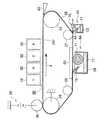
図1には、本実施形態の液滴吐出装置としてのインクジェット記録装置12が示されている。インクジェット記録装置12の筐体14内の下部には給紙トレイ16が備えられており、給紙トレイ16内に積層された用紙Pをピックアップロール18で1枚ずつ取り出すことができる。取り出された用紙Pは、所定の搬送経路22を構成する複数の搬送ローラ対20で搬送される。 FIG. 1 shows an ink
給紙トレイ16の上方には、無端状の搬送ベルト28が、駆動ロール24及び従動ロール26、27、29に張架されている。駆動ロール24と従動ロール26とが、略水平に配設され、その下方において、従動ロール27と従動ロール29とが、略水平に配設されている。 Above the
また、搬送ベルト28の上方には記録ヘッドアレイ30が配置されており、駆動ロール24と従動ロール26との間の搬送ベルト28の平坦部分28Fに対向している。この対向した領域が、記録ヘッドアレイ30からインク滴が吐出される吐出領域SEとなっている。搬送経路22で搬送された用紙Pは、搬送ベルト28で保持されてこの吐出領域SEに至り、記録ヘッドアレイ30に対向した状態で、記録ヘッドアレイ30から画像情報に応じたインク滴が付着される。 A
記録ヘッドアレイ30は、本実施形態では、有効な記録領域が用紙Pの幅(搬送方向と直交する方向の長さ)以上とされた長尺状とされ、イエロー(Y)、マゼンタ(M)、サイアン(C)、及びブラック(K)の4色それぞれに対応した4つの液滴吐出ヘッドとしてのインクジェット記録ヘッド(以下、記録ヘッドという)32がベルト回転方向に沿って配置されており、フルカラーの画像を記録可能になっている。 In this embodiment, the
各記録ヘッド32は、ヘッド駆動回路(図示省略)によって駆動される。ヘッド駆動回路は、たとえば、画像情報に応じてインク滴の吐出タイミングや使用するインク吐出口(ノズル)を決め、駆動信号を記録ヘッド32に送る構成である。 Each
また、記録ヘッドアレイ30は、搬送方向と直交する方向に不動とされていてもよいが、必要に応じて移動するように構成しておくと、マルチパスによる画像記録で、より解像度の高い画像を記録したり、記録ヘッド32の不具合を記録結果に反映させないようにしたりできる。 The
記録ヘッドアレイ30の両側には、それぞれの記録ヘッド32に対応した4つのメンテナンスユニット34が配置されている。図2に示すように、記録ヘッド32に対してメンテナンスを行う場合には、記録ヘッドアレイ30が上方へ移動され、搬送ベルト28との間に構成された間隙にメンテナンスユニット34が移動して入り込む。そして、ノズル面に対向した状態で、所定のメンテナンス動作(吸引、ワイピング、キャッピング等)を行う。 Four
また、記録ヘッドアレイ30の上方には、各色のインクを貯留するインクタンク35が配置されている。各インクタンク35には、各記録ヘッド32が接続されている。 Further, an
なお、各記録ヘッド32は、未使用ノズルの目詰まりを防止することを目的とした画像形成とは無関係のインク滴の吐出(所謂、予備吐出)を行う。 Each
図3に示すように、記録ヘッドアレイ30のベルト回転方向上流側には、電源38が接続された帯電ロール36が配置されている。帯電ロール36は、従動ロール26との間で搬送ベルト28及び用紙Pを挟みつつ従動し、用紙Pを搬送ベルト28に押圧する。この際、接地された従動ロール26との間に所定の電位差が生じるため、用紙Pに電荷を与えて用紙Pを搬送ベルト28に静電吸着させることができる。 As shown in FIG. 3, a charging
記録ヘッドアレイ30のベルト回転方向下流側には、剥離爪40が配置されており、用紙Pを搬送ベルト28から剥離させる。剥離された用紙Pは、剥離爪40の搬送方向下流側で排出経路44を構成する複数の排出ローラ対42で搬送され、筐体14の上部に設けられた排紙トレイ46に排出される。 A
また、剥離爪40のベルト回転方向下流側には、ベルトクリーニングユニット48が配置されている。このベルトクリーニングユニット48は、搬送ベルト28の従動ロール27に巻き掛けられた部分に接触し、搬送ベルト28に付着したインク等を掻き取る、清掃部材としてのブレード49と、ブレード49によって搬送ベルト28から掻き取られたインク等を回収する回収ボックス51と、を備えている。 A
ブレード49は、従動ロール27の外径方向(搬送ベルト28の遠心方向)に対してベルト回転方向上流側へ傾斜し、且つ、搬送ベルト28側から反搬送ベルト28側へ下側に傾斜するように、回収ボックス51に支持されている。また、回収ボックス51の底部には、吸収体53が敷き詰められており、ブレード49から滴下する液体が吸収体53に吸収される。 The
また、オイル塗布ユニット64とバックアッププレート66とが、従動ロール26と従動ロール27との間で搬送ベルト28を間に置いて対向している。オイル塗布ユニット64は、搬送ベルト28の外周面に対向し、バックアッププレート66は、搬送ベルト28の内周面に当接している。 Further, the
オイル塗布ユニット64は、ケース68と、ケース68に回転可能に支持された塗布部材としてのオイル塗布ロール71と、ケース68に支持されたオイル用ブレード73と、を備えている。オイル塗布ロール71は、搬送ベルト28を間に置いてバックアップブレード66に圧接されており、搬送ベルト28に従動して回転する。また、オイル塗布ロール71は、ポリエチレンやウレタン等の多孔質体で形成され、第1の液体としてのシリコーンオイルを含浸しており、搬送ベルト28にシリコーンオイルを塗布する。これに対して、記録ヘッド32から吐出されるインクは、水性インクとなっている。このため、用紙ジャム時の不必要なインク吐出、又は搬送ベルト28上へ向けて行われる予備吐出等によって搬送ベルト28にインクが付着した場合、搬送ベルト28上のシリコーンオイルの膜の撥水効果によりインクが濡れ広がることなく滴形状を保つ。従って、インクが搬送ベルト28に付着する力の増加を抑制でき、ブレード49によって搬送ベルト28をクリーニングする際、インクが搬送ベルト28から容易に剥離される。 The
ここで、予備吐出は、記録ヘッド32内のインクの増粘を防止するために、数十秒に1回等の短い周期で行われるので、本実施形態のように、常時、搬送ベルト28上にシリコーンオイルの膜を形成しておくことは効果的である。 Here, since the preliminary ejection is performed at a short cycle such as once every several tens of seconds in order to prevent thickening of the ink in the
なお、オイル塗布ロール71は、駆動ロールとしても良い。この場合、オイル塗布ロール71が搬送ベルト28に対して滑ることを防止できる。 The
また、オイル用ブレード73は、オイル塗布ロール71より搬送ベルト28の回転方向下流側で搬送ベルト28に当接しており、搬送ベルト28に塗布されたシリコーンオイルの余剰分を掻き落し、シリコーンオイルの膜厚を所定の厚みにする。なお、オイル用ブレード73は、フッ素ゴム、NBR等のゴム、SUS等の金属の薄板、ポリウレタン、PET等の樹脂フィルム等を用いる。 The
また、ケース68の底部には、スポンジ等の吸収部材77が敷き詰められており、この吸収部材77が、オイル用ブレード73によって搬送ベルト28から掻き取られたシリコーンオイルを吸収する。 Further, an absorbing
また、搬送ベルト28は、PET、PI、PA、PC等の樹脂、又はCR、NBR、HNBR、ウレタンゴム等のゴム材料で形成し、表面にコーティングを施したもの等を使用する。また、ブレード49は、フッ素ゴム、NBR、HNBR等のゴム材料で形成したもの、SUS等の金属の薄板、ポリウレタン、PET等の樹脂で形成したフィルム等を使用する。また、オイル塗布ロール71のロール部は、ポリエステルやポリアミド等で形成された不織布が好適であるが、インクを所定量含浸可能であれば、他のものに変えても良い。 The
また、オイル塗布ロール71によって搬送ベルト28に塗布する第1の液体としては、上述したようにシリコーンオイルを使用し、インクは水性インクを使用する。ここで、第1の液体は、インクをはじく液体が適しており、水性インクに対しては、シリコーンオイルの他に、オレイン酸、リノール酸等の高級脂肪酸、フタル酸ジブチル、フタル酸ジイソデシル、マレイン酸ジブチル等の可塑剤、n−デカノール、ジメチルブタノール等の非水溶性のアルコール類、フッ素オイル、鉱物オイル、植物オイル等の撥水性を有する液体が使用可能である。また、油性インクに対しては、水等の撥油性が高い液体が使用可能である。 Further, as described above, silicone oil is used as the first liquid applied to the
また、第1の液体の搬送ベルト28への塗布を安定させるためには、塗布液の動粘度を10〜104mm2/sの範囲にすることが望ましく、50〜102mm2/sの範囲にすることがより望ましい。In order to stabilize the application of the first liquid to the
また、第1の液体の塗布厚が厚すぎると、用紙Pにオイルが浸透して用紙Pがインクをはじいたり、帯電ロール36への付着力が多くなり過ぎて用紙Pの搬送ベルト28への吸着不良が発生したりする等の問題が発生する可能性があり、逆に、第1の液体の塗布厚が薄すぎると、ブレード49によるインクのクリーニングが良好に行われなくなるので、第1の液体の塗布厚を適当な範囲に設定することが必要である。第1の液体の塗布厚の適当な範囲は、1nm〜20μmである。 On the other hand, if the coating thickness of the first liquid is too thick, the oil penetrates the paper P and the paper P repels ink, or the adhesive force to the charging
また、第1の液体は常温にて不揮発性である必要がある。具体的には蒸気圧が25℃で13.33Pa以下である。また、第1の液体は、インクと相溶しない性質である必要がある。具体的には、インクに対する溶解度が常温(25℃)で0.1wt%以下である。 The first liquid needs to be non-volatile at room temperature. Specifically, the vapor pressure is 13.33 Pa or less at 25 ° C. Further, the first liquid needs to have a property that is not compatible with ink. Specifically, the solubility in ink is 0.1 wt% or less at normal temperature (25 ° C.).
また、第1の液体は、搬送ベルト28上で濡れ広がる必要があるので、下記(A)式の関係が必要である。但し、図4に示すように、第1の液体Tの表面張力をγ0、搬送ベルト28の臨界表面張力γbとする。なお、臨界表面張力とは、種々の液体の表面張力と固体表面の接触角θとの関係において、cosθを1に補正したとき(すなわち液体の固体表面に対する接触角が0°となったとき)の表面張力をいう。一般に固体表面は、その表面が有する臨界表面張力よりも小さい表面張力を持つ液体によく濡れる。Further, since the first liquid needs to spread on the
γ0<γb…(A)
また、第1の液体Tに撥水性を持たせるためには、下記(B)式の関係が必要となる。但し、インクIの表面張力をγiとする。γ0 <γb (A)
Further, in order to give the first liquid T water repellency, the relationship of the following formula (B) is required. However, the surface tension of the ink I is γi .
γ0<γi…(B)
これによって、インクIは第1の液体Tの膜上で濡れ広がることなく、滴形状を保つ。γ0 <γi (B)
As a result, the ink I maintains a droplet shape without spreading on the film of the first liquid T.
ところで、図5(A)、(B)に示すように、インクジェット記録装置12には、液体供給手段としての液体供給機構70が設けられている。この液体供給機構70は、ノズル72と、チューブ74、75と、タンク76と、ポンプ78と、移動手段としての移動機構80とを備えている。 Incidentally, as shown in FIGS. 5A and 5B, the ink
タンク76には、第2の液体としてのシリコーンオイルが貯留されている。 The
移動機構80は、モータ82と、モータ82の回転軸であるボールネジ84と、ネジ作用によってボールネジ84に結合された管継ぎ手部86と、ボールネジ84と共に管継ぎ手部86を支持するシャフト87とを備えており、モータ82の駆動によりボールネジ84を回転させて管継ぎ手部86をボールネジ84の軸方向へ移動させる。 The moving
ボールネジ84、シャフト87は、ブレード49のベルト回転方向上流側且つ剥離爪40のベルト回転方向下流側且つブレード49の側方において、搬送ベルト28の幅方向一端側から他端側へ延在している。このため、管継ぎ手部86は、ボールネジ84の回転によって、ブレード49の長手方向に沿って移動される。 The
また、管継ぎ手部86は、ノズル72の一端部とチューブ74の一端部とを接続している。また、タンク76の下部には、チューブ75の一端部が接続されている。さらに、チューブ75の他端部とチューブ74の他端部とはポンプ78に接続されており、ポンプ78が駆動されると、タンク76に貯留されたシリコーンオイルが、チューブ75からチューブ74へ、チューブ74からノズル72へ流れてノズル72の液体流出口72Aから流出する。 Further, the pipe
ここで、液体流出口72Aは、ブレード49と搬送ベルト28との接触部に向けられており、ブレード49と搬送ベルト28との接触部へ向けてシリコーンオイルを流出する。 Here, the
また、モータ82、ポンプ78は、制御部88によって制御されており、各記録ヘッド32が予備吐出を行うタイミングと同期して駆動され、液体流出口72Aからシリコーンオイルを流出しているノズル72が、ブレード49と搬送ベルト28との接触部に沿って移動する。これによって、ブレード49と搬送ベルト28との接触部に溜るシリコーンオイルの量が増加する。 Further, the
ここで、液体供給機構70は、用紙Pの搬送領域のベルト回転方向下流側、且つ、ブレード49よりベルト回転方向上流側から、ブレード49と搬送ベルト28との接触部へシリコーンオイルを供給する。これによって、用紙Pの搬送領域においては、搬送ベルト28上のシリコーンオイルの塗布量(塗布厚)を、上述した適量である範囲内に抑えた上で、ブレード49と搬送ベルト28との接触部に溜るシリコーンオイルの量を増加させることが可能となる。 Here, the
従って、用紙Pや帯電ロール36等の搬送ベルト28に接触する物へのシリコーンオイルの付着量を増加させることなく、ブレード49と搬送ベルト28との接触部からブレード49の反接触部側へのインクIのスムーズな移動を確保でき、ブレード49による搬送ベルト28の清掃不良を抑制できる。 Accordingly, without increasing the amount of silicone oil adhering to the material that contacts the
また、ノズル72の液体流出口72Aをブレード49と搬送ベルト28との接触部に近接させたことで、液体流出口72Aから流出されるシリコーンオイルの流圧によって、ブレード49と搬送ベルト28との接触部からインクI及びインクIをトラップしたシリコーンオイルをブレード49側へ流すことができる。従って、ブレード49と搬送ベルト28との接触部からブレード49の反接触部側へのインクIのスムーズな移動を確保できる。 Further, by bringing the
また、移動機構80によってノズル72をブレード49と搬送ベルト28との接触部に沿って移動させるように構成したことで、ブレード49と搬送ベルト28との接触部の全域にノズル72を設ける場合と比較して、ノズル72の流路面積の総量が少なくなり、ポンプ78の動力が同じ場合でもノズル72に発生する圧力が大きくなる。 In addition, since the moving
これによって、ブレード49と搬送ベルト28との接触部の全域にノズル72を設ける場合と比較して、ブレード49と搬送ベルト28との接触部に供給されるシリコーンオイルの量の位置毎のバラツキを抑制できる。 As a result, the amount of silicone oil supplied to the contact portion between the
また、シリコーンオイルを、ポンプ78により、タンク76から搬送ベルト28へ供給することによって、タンク76の位置に関わらず、タンク76から搬送ベルト28へシリコーンオイルを供給できるので、タンク76の配置の制約を低減できる。 Further, by supplying the silicone oil from the
なお、第2の液体は、流圧によりインクIを押し流すことができる程度の粘度(10〜1000cst)を有する液体である必要があり、不揮発性が有り、電気的に高抵抗(108Ω・cm以上)である液体であることが望ましい。不揮発性を有する液体であれば、周辺環境の汚染を防止できる。また、電気的に高抵抗な液体であれば、帯電ロール36による搬送ベルト28の異常帯電、用紙Pの搬送ベルト28への吸着不良を抑制できる。Note that the second liquid needs to be a liquid having a viscosity (10 to 1000 cst) that allows the ink I to be swept away by the flow pressure, has a non-volatile property, and has an electrically high resistance (108 Ω · It is desirable that the liquid be cm or more. If the liquid is non-volatile, contamination of the surrounding environment can be prevented. Further, if the liquid is an electrically high resistance, abnormal charging of the
例えば、本実施形態で用いたシリコーンオイル等のオイルが好適であるが、イソプロピルアルコール等のアルコール類や水等も適用可能である。第1の液体と同様に、第2の液体をシリコーンオイルにすることによって、互いに性質を変化させ合うことが無いので、第1の液体と第2の液体とを、回収し、インクを分離した後に再利用することが可能となる。また、第2の液体を、第1の液体とは別の液体にすることによって、例えば、水等の安価な液体を利用できる等、コスト面で有利になる場合がある。 For example, oil such as silicone oil used in this embodiment is suitable, but alcohols such as isopropyl alcohol, water, and the like are also applicable. Like the first liquid, the second liquid is made of silicone oil so that the properties of the second liquid do not change with each other. Therefore, the first liquid and the second liquid are collected and the ink is separated. It can be reused later. Further, by making the second liquid different from the first liquid, it may be advantageous in terms of cost, for example, an inexpensive liquid such as water can be used.
また、タンク76から搬送ベルト28への第2の液体の供給は、図6に示すように、水頭差を利用して行っても良い。この方法は、タンク36に貯留された第2の液体の液面が、ノズル72の液体流出口72Aより常に高くなるように、タンク36とノズル72との位置を設定することで可能となる。なお、この方法によるとポンプが不要となるので、コストを低減できる。 Further, the second liquid may be supplied from the
また、吸引機構70を駆動させるタイミングは、各記録ヘッド32が予備吐出を1回行う毎でも良いし、また、各記録ヘッド32が予備吐出を所定回数行う毎でも良い。また、ノズル72の液体流出口72Aは、ブレード49に接触させても良いし、ブレード49と搬送ベルト28とに接触させても良いし、また、ブレード49と搬送ベルト28とに非接触としても良い。 The timing of driving the
また、ノズル72、チューブ74、75は、樹脂、ゴム、金属等の管材を用いれば良いが、チューブ74、75は、可撓性を有する管材であることが望ましい。 The
さらに、本実施形態では、ノズル72の液体流出口72Aを、ブレード49と搬送ベルト28との接触部に向けたが、図7に示すように、剥離爪40のベルト回転方向下流側且つブレード49のベルト回転方向上流側において、搬送ベルト28へ向けられていれば良い。 Furthermore, in this embodiment, the
次に、本発明の第2実施形態について説明する。なお、第1実施形態と同様の構成には同一の符号を付し、説明は省略する。 Next, a second embodiment of the present invention will be described. In addition, the same code | symbol is attached | subjected to the structure similar to 1st Embodiment, and description is abbreviate | omitted.
図8(A)に示すように、液滴吐出装置としてのインクジェット記録装置200には、液体供給手段としての液体供給機構96が設けられている。この液体供給機構96は、液体流路列としてのノズルアレイ98と、チューブ75、94と、インクタンク76と、ポンプ78とを備えている。ノズルアレイ98は、ブレード49の長手方向へ所定間隔おきにブレード49に形成された複数のノズル99からなり、各ノズル99は、ブレード49の幅方向に延びる孔である。 As shown in FIG. 8A, the ink
また、タンク76の下部には、チューブ75の一端部が接続され、チューブ75の他端部とチューブ94の一端部とがポンプ78に接続されている。さらに、チューブ94の他端側は複数に分岐して各々、各ノズル99の一端部に接続されており、ポンプ78が駆動されると、タンク76に貯留されたシリコーンオイルが、チューブ75からチューブ94へ、チューブ94で分岐して各ノズル99へ流れて各ノズル99の液体流出口99Aから流出する。 Further, one end of the
ここで、図8(B)に示すように、ブレード49は、従動ロール27の外径方向(搬送ベルト28の遠心方向)に対してベルト回転方向上流側へ傾斜しており、先端側(幅方向の搬送ベルト側)の一対のエッジ部のうちのベルト回転方向上流側のエッジ部49Aを搬送ベルト28に接触させている。このため、エッジ部49Aのベルト回転方向上流側に位置し、ベルト回転方向上流側を向いたブレード49の板面49Dに、第1の液体としてのシリコーンオイルが溜る。 Here, as shown in FIG. 8B, the
このため、ノズル99の他端側をベルト回転方向上流側へ屈曲させて、液体流出口99Aをブレード49の板面49Dに形成することによって、ブレード49と搬送ベルト28との接触部に第1の液体としてのシリコーンオイルと第2の液体としてのシリコーンオイルとを溜めることを可能にしている。 Therefore, the other end side of the
また、ブレード49と搬送ベルト28との接触部に向けられた複数の液体流出口99Aが、ブレード49の長手方向一端側から他端側まで所定間隔で配列されており、ブレード49と搬送ベルト28との接触部全域へシリコーンオイルが供給されるようになっている。 A plurality of
これによって、第1実施形態と同様、用紙Pの搬送領域においては、搬送ベルト28上のシリコーンオイルの塗布量(塗布厚)を、上述した適量である範囲内に抑えた上で、ブレード49と搬送ベルト28との接触部に溜るシリコーンオイルの量を増加させることができる。 Thus, as in the first embodiment, in the conveyance region of the paper P, the application amount (application thickness) of the silicone oil on the
従って、用紙Pや帯電ロール36等の搬送ベルト28に接触する物へのシリコーンオイルの付着量を増加させることなく、ブレード49と搬送ベルト28との接触部からブレード49の反接触部側へのインクIのスムーズな移動を確保でき、ブレード49による搬送ベルト28の清掃不良を抑制できる。 Accordingly, without increasing the amount of silicone oil adhering to the material that contacts the
ここで、ノズルアレイ98をブレード49と搬送ベルト28との接触部の全長以上の長さとしたことで、ノズル99を移動させることなく、ブレード49と搬送ベルト28との接触部全域にシリコーンオイルを供給することができる。従って、ノズル99を移動させる機構が不要となるので、液体供給機構96のコストを抑制できる。 Here, since the
なお、全てのノズル99を1個のポンプ78に接続した例について説明したが、1本のノズル99毎にポンプ78を設けて接続しても良いし、ポンプ78を複数設けて、各ポンプ78にノズル99を複数本ずつ接続しても良い。 Although an example in which all the
なお、図9に示すように、本実施形態におけるノズルアレイ98は、幅方向に延びる複数の溝49Sが形成されたプレート49Tと、長手方向に配列された複数の吸引口99Aが形成された天板プレート49Uとを接着、溶着等の方法により接合することで形成できる。 As shown in FIG. 9, the
また、ブレード49の材料としては、ゴム(例えば、フッ素ゴム、NBR、HNBR等)、金属(SUSの薄板等)、樹脂(例えば、ポリウレタン、PETフィルム等)等が適用可能である。 As the material of the
また、吸引口99Aの孔径、ピッチは、吸引性能を維持できるように適宜設定すればよい。 The hole diameter and pitch of the
次に、本発明の第3実施形態について説明する。なお、第1、第2実施形態と同様の構成には同一の符号を付し、説明は省略する。 Next, a third embodiment of the present invention will be described. In addition, the same code | symbol is attached | subjected to the structure similar to 1st, 2nd embodiment, and description is abbreviate | omitted.
図10(A)に示すように、液滴吐出装置としてのインクジェット記録装置300には、液体供給手段としての液体供給機構102が設けられている。この液体供給機構102は、液体流路列としてのノズルアレイ103と、チューブ75、94と、インクタンク76と、ポンプ78とを備えている。ノズルアレイ103は、ブレード49の長手方向へ所定間隔おきにブレード49に形成された複数のノズル105からなり、各ノズル105は、ブレード49の幅方向に延びる孔である。 As shown in FIG. 10A, an ink
また、タンク76の下部には、チューブ75の一端部が接続され、チューブ75の他端部とチューブ94の一端部とがポンプ78に接続されている。さらに、チューブ94の他端側は複数に分岐して各々、各ノズル105の一端部に接続されており、ポンプ78が駆動されると、タンク76に貯留されたシリコーンオイルが、チューブ75からチューブ94へ、チューブ94で分岐して各ノズル105へ流れて各ノズル105の液体流出口105Aから流出する。 One end of a
ここで、図10(B)に示すように、ブレード49は、従動ロール27の外径方向(搬送ベルト28の遠心方向)に対してベルト回転方向下流側へ傾斜しており、先端側(幅方向の搬送ベルト側)の一対のエッジ部のうちのベルト回転方向下流側のエッジ部49Cを搬送ベルト28に接触させている。このため、搬送ベルト28と対向するブレード49の先端面49Aにインクが溜る。 Here, as shown in FIG. 10B, the
このため、ノズル105を先端面49Aまで真っ直ぐ延ばして、液体流出口105Aをブレード49の先端面49Bに形成することによって、ブレード49と搬送ベルト28との接触部に第1の液体としてのシリコーンオイルと第2の液体としてのシリコーンオイルとを溜めることを可能にしている。 For this reason, by extending the
なお、図11(A)に示すように、本実施形態におけるノズルアレイ103は、ブレード49の幅方向に延びる複数の溝49Sが形成されたプレート49Tと、天板プレート49Vとを接着、溶着等の方法により接合することで形成できる。 As shown in FIG. 11A, the
また、図11(B)に示すように、溝49Sと溝49Sとの間に形成された壁部49Hの先端面49B側の端部を三角形状に形成することで、液体流出口105Aを先端面49Bに隙間無く形成することができる。これによって、ブレード49と搬送ベルト28との接触部において液体流出口105Aから流出したシリコーンオイルが広がり易くなるので、ブレード49と搬送ベルト28との接触部に溜るシリコーンオイルの量が位置毎のバラツキを抑制できる。 Further, as shown in FIG. 11B, the end of the wall 49H formed between the
なお、第1乃至第3実施形態では、インクジェット記録装置を例に取って本発明を説明したが、本発明は、インクジェット記録装置に限らず、高分子フィルム上に着色インクを吐出して行うディスプレイ用のカラーフィルターの作製、有機EL溶液を基板上に吐出させて行うELディスプレイパネルの形成など、様々な工業的用途を対象とした液滴吐出装置一般に対して、適用可能である。 In the first to third embodiments, the present invention has been described by taking an inkjet recording apparatus as an example. However, the present invention is not limited to an inkjet recording apparatus, and the display is performed by discharging colored ink onto a polymer film. The present invention can be applied to a general liquid droplet ejection apparatus for various industrial uses such as production of color filters for liquid crystal and formation of an EL display panel which is performed by discharging an organic EL solution onto a substrate.
また、本発明の液滴吐出装置における「液滴吐出ヘッド」には、記録媒体や中間転写体等の回転体に向けて液滴を吐出する手段であれば広く含まれ、例えば、用紙Pの幅よりも短尺で用紙Pの幅方向に移動しながらインク滴を吐出するインクジェット記録ヘッドなどが含まれる。 The “droplet discharge head” in the droplet discharge apparatus of the present invention includes a wide range of means for discharging droplets toward a rotating body such as a recording medium or an intermediate transfer member. Examples include an inkjet recording head that ejects ink droplets while moving in the width direction of the paper P with a length shorter than the width.
また、本発明の液滴吐出装置における「搬送部材」には、記録媒体を保持して搬送する部材であれば広く含まれる。例えば、記録媒体を周面で保持して回転するドラムなどが含まれる。 In addition, the “conveying member” in the droplet discharge apparatus of the present invention includes a wide range of members as long as they hold and convey a recording medium. For example, a drum that rotates while holding a recording medium on its peripheral surface is included.
また、本発明の液滴吐出装置における「清掃部材」には、担持体に付着した液滴を清掃する部材であれば広く含まれ、例えば、クリーニングウェブなどが含まれる。 Further, the “cleaning member” in the droplet discharge device of the present invention includes a wide range of members as long as it is a member that cleans droplets attached to the carrier, and includes, for example, a cleaning web.
また、本発明の液滴吐出装置における「塗布部材」は、第1の液体を搬送部材に塗布する部材であれば広く含まれ、例えば、第1の液体を含浸したパッドなどが含まれる。 In addition, the “application member” in the droplet discharge device of the present invention is widely included as long as it is a member that applies the first liquid to the transport member, and includes, for example, a pad impregnated with the first liquid.
さらに、本発明の液滴吐出装置における「液体供給手段」は、第2の液体を搬送部材に塗布する部材であれば広く含まれ、例えば、第2の液体を含浸したロール、パッドなどが含まれる。 Further, the “liquid supply means” in the droplet discharge device of the present invention is widely included as long as it is a member that applies the second liquid to the transport member, and includes, for example, a roll, a pad, etc. impregnated with the second liquid. It is.
12 インクジェット記録装置(液滴吐出装置)
28 搬送ベルト(搬送部材)
32 インクジェット記録ヘッド(液滴吐出ヘッド)
49 ブレード(清掃部材)
49B 先端面(端面)
49D 板面
70 液体供給機構(液体供給手段)
71 オイル塗布ロール(塗布部材)
72 ノズル(液体流路)
72A 液体流出口
74 チューブ(液体流路)
75 チューブ(液体流路)
76 タンク
78 ポンプ
80 移動機構(移動手段)
94 チューブ(液体流路)
96 液体供給機構(液体供給手段)
98 ノズルアレイ(液体流路列)
99 ノズル(液体流路)
99A 液体流出口
102 液体供給機構(液体供給手段)
103 ノズルアレイ(液体流路列)
105 ノズル(液体流路)
105A 液体流出口
200 インクジェット記録装置(液滴吐出装置)
300 インクジェット記録装置(液滴吐出装置)
P 用紙(記録媒体)12 Inkjet recording device (droplet ejection device)
28 Conveying belt (conveying member)
32 Inkjet recording head (droplet ejection head)
49 Blade (cleaning member)
49B End face (end face)
71 Oil application roll (application member)
72 nozzles (liquid flow path)
75 Tube (liquid flow path)
76
94 Tube (liquid flow path)
96 Liquid supply mechanism (liquid supply means)
98 Nozzle array (liquid flow path array)
99 nozzles (liquid flow path)
103 Nozzle array (liquid flow path array)
105 nozzle (liquid flow path)
300 Inkjet recording device (droplet ejection device)
P paper (recording medium)
Claims (9)
Translated fromJapanese無端状の回転体であり、記録媒体を保持し前記液滴吐出ヘッドに対向させて搬送する搬送部材と、
記録媒体の搬送領域外で前記搬送部材に接触して前記搬送部材を清掃する清掃部材と、
前記清掃部材より前記搬送部材の回転方向下流側、且つ、記録媒体の搬送領域より前記搬送部材の回転方向上流側において、前記液滴吐出ヘッドから吐出される液体をはじく性質を有する第1の液体を前記搬送部材に塗布する塗布部材と、
記録媒体の搬送領域より前記搬送部材の回転方向下流側、且つ、前記清掃部材より前記搬送部材の回転方向上流側から、前記清掃部材と前記搬送部材との接触部へ第2の液体を供給する液体供給手段と、
を有することを特徴とする液滴吐出装置。A droplet discharge head for discharging liquid in droplets;
A conveying member that is an endless rotator and holds a recording medium and conveys the recording medium to face the droplet discharge head;
A cleaning member that contacts the transport member outside the recording medium transport region and cleans the transport member;
A first liquid having a property of repelling the liquid ejected from the liquid droplet ejection head on the downstream side in the rotational direction of the transport member from the cleaning member and on the upstream side in the rotational direction of the transport member from the transport area of the recording medium. A coating member for coating the conveying member;
The second liquid is supplied to the contact portion between the cleaning member and the conveying member from the recording medium conveying area on the downstream side in the rotation direction of the conveying member and from the cleaning member on the upstream side in the rotation direction of the conveying member. Liquid supply means;
A droplet discharge apparatus comprising:
前記第2の液体を貯留するタンクと、
前記タンクから前記搬送部材へ延びる液体流路と、
を有し、前記タンクに貯留された前記第2の液体を水頭差により前記搬送部材へ流出させることを特徴とする請求項1に記載の液滴吐出装置。The liquid supply means includes
A tank for storing the second liquid;
A liquid flow path extending from the tank to the transport member;
The droplet discharge apparatus according to claim 1, wherein the second liquid stored in the tank is caused to flow out to the transport member due to a water head difference.
前記第2の液体を貯留するタンクと、
前記タンクから前記搬送部材へ延びる液体流路と、
前記タンクに貯留された液体を前記タンクから前記搬送部材へ流出させるポンプと、
を有することを特徴とする請求項1に記載の液滴吐出装置。The liquid supply means includes
A tank for storing the second liquid;
A liquid flow path extending from the tank to the transport member;
A pump for causing the liquid stored in the tank to flow out of the tank to the transport member;
The droplet discharge device according to claim 1, wherein:
前記液体流路の液体流出口は、前記搬送部材の回転方向上流側を向いた前記ブレードの板面に形成されたことを特徴とする請求項5に記載の液滴吐出装置。The cleaning member is a blade inclined to the upstream side in the rotation direction of the transport member with respect to the centrifugal direction of the transport member,
6. The liquid droplet ejection apparatus according to claim 5, wherein the liquid outlet of the liquid flow path is formed on a plate surface of the blade facing the upstream side in the rotation direction of the transport member.
前記液体流路の液体流出口は、前記搬送部材と対向する前記ブレードの端面に形成されたことを特徴とする請求項5に記載の液滴吐出装置。The cleaning member is a blade inclined to the downstream side in the rotation direction of the transport member with respect to the centrifugal direction of the transport member,
The liquid droplet ejection apparatus according to claim 5, wherein a liquid outlet of the liquid channel is formed on an end surface of the blade facing the conveying member.
Priority Applications (1)
| Application Number | Priority Date | Filing Date | Title |
|---|---|---|---|
| JP2006237733AJP2008055837A (en) | 2006-09-01 | 2006-09-01 | Droplet ejection apparatus |
Applications Claiming Priority (1)
| Application Number | Priority Date | Filing Date | Title |
|---|---|---|---|
| JP2006237733AJP2008055837A (en) | 2006-09-01 | 2006-09-01 | Droplet ejection apparatus |
Publications (1)
| Publication Number | Publication Date |
|---|---|
| JP2008055837Atrue JP2008055837A (en) | 2008-03-13 |
Family
ID=39239133
Family Applications (1)
| Application Number | Title | Priority Date | Filing Date |
|---|---|---|---|
| JP2006237733APendingJP2008055837A (en) | 2006-09-01 | 2006-09-01 | Droplet ejection apparatus |
Country Status (1)
| Country | Link |
|---|---|
| JP (1) | JP2008055837A (en) |
Cited By (8)
| Publication number | Priority date | Publication date | Assignee | Title |
|---|---|---|---|---|
| JP2009242018A (en)* | 2008-03-28 | 2009-10-22 | Konica Minolta Ij Technologies Inc | Recording medium carrying device and inkjet recorder |
| JP2011031619A (en)* | 2009-08-04 | 2011-02-17 | Xerox Corp | Drum maintenance system for reducing duplex dropout |
| JP2013067155A (en)* | 2010-11-26 | 2013-04-18 | Ricoh Co Ltd | Inkjet recording device |
| KR101373310B1 (en) | 2012-03-14 | 2014-03-11 | 주식회사 디지아이 | Printing machine |
| JP2014124875A (en)* | 2012-12-27 | 2014-07-07 | Seiko Epson Corp | Liquid jet apparatus, liquid receiving device, and liquid scraping method |
| EP2777941A1 (en)* | 2013-03-11 | 2014-09-17 | Seiko Epson Corporation | Recording apparatus and recording method |
| JP2015044356A (en)* | 2013-08-28 | 2015-03-12 | セイコーエプソン株式会社 | Liquid ejector |
| US9144982B2 (en) | 2012-12-27 | 2015-09-29 | Seiko Epson Corporation | Liquid ejecting apparatus |
- 2006
- 2006-09-01JPJP2006237733Apatent/JP2008055837A/enactivePending
Cited By (9)
| Publication number | Priority date | Publication date | Assignee | Title |
|---|---|---|---|---|
| JP2009242018A (en)* | 2008-03-28 | 2009-10-22 | Konica Minolta Ij Technologies Inc | Recording medium carrying device and inkjet recorder |
| JP2011031619A (en)* | 2009-08-04 | 2011-02-17 | Xerox Corp | Drum maintenance system for reducing duplex dropout |
| JP2013067155A (en)* | 2010-11-26 | 2013-04-18 | Ricoh Co Ltd | Inkjet recording device |
| KR101373310B1 (en) | 2012-03-14 | 2014-03-11 | 주식회사 디지아이 | Printing machine |
| JP2014124875A (en)* | 2012-12-27 | 2014-07-07 | Seiko Epson Corp | Liquid jet apparatus, liquid receiving device, and liquid scraping method |
| US9144982B2 (en) | 2012-12-27 | 2015-09-29 | Seiko Epson Corporation | Liquid ejecting apparatus |
| EP2777941A1 (en)* | 2013-03-11 | 2014-09-17 | Seiko Epson Corporation | Recording apparatus and recording method |
| US8985737B2 (en) | 2013-03-11 | 2015-03-24 | Seiko Epson Corporation | Recording apparatus and recording method |
| JP2015044356A (en)* | 2013-08-28 | 2015-03-12 | セイコーエプソン株式会社 | Liquid ejector |
Similar Documents
| Publication | Publication Date | Title |
|---|---|---|
| JP4752600B2 (en) | Droplet discharge device | |
| JP4752599B2 (en) | Droplet discharge device | |
| JP2008055837A (en) | Droplet ejection apparatus | |
| JP4502018B2 (en) | Droplet discharge device | |
| JP4696930B2 (en) | Droplet discharge device | |
| CN100572086C (en) | droplet discharge device | |
| JP4715631B2 (en) | Droplet discharge device | |
| JP4702250B2 (en) | Droplet discharge device | |
| JP5573521B2 (en) | Liquid ejection apparatus and liquid ejection method | |
| JP4640067B2 (en) | Droplet discharge device | |
| JP2008044721A (en) | Droplet discharge device | |
| JP2006256840A (en) | Droplet ejection device | |
| JP4775124B2 (en) | Droplet discharge device | |
| JP2007283634A (en) | Liquid droplet ejection apparatus | |
| US8857950B2 (en) | Liquid ejection device and liquid ejection method | |
| JP2008179094A (en) | Liquid droplet discharge device | |
| JP2008012846A (en) | Image forming device | |
| JP2008049661A (en) | Liquid droplet discharge apparatus and method for cleaning liquid droplet discharge head | |
| JP2006305989A (en) | Liquid droplet discharge apparatus and method for cleaning liquid droplet discharge head | |
| JP4449914B2 (en) | Droplet discharge device | |
| JP2008023777A (en) | Liquid droplet discharge apparatus | |
| JP2013139132A (en) | Liquid ejecting apparatus | |
| JP2008213351A (en) | Droplet discharge apparatus and image forming apparatus | |
| JP2008254235A (en) | Capping mechanism and liquid droplet ejector | |
| JP2007210113A (en) | Liquid droplet discharge apparatus |