JP2008055227A - Surgical purse string suturing instrument and surgical needle - Google Patents
Surgical purse string suturing instrument and surgical needleDownload PDFInfo
- Publication number
- JP2008055227A JP2008055227AJP2007297352AJP2007297352AJP2008055227AJP 2008055227 AJP2008055227 AJP 2008055227AJP 2007297352 AJP2007297352 AJP 2007297352AJP 2007297352 AJP2007297352 AJP 2007297352AJP 2008055227 AJP2008055227 AJP 2008055227A
- Authority
- JP
- Japan
- Prior art keywords
- jaw
- needle
- jaws
- tissue
- tooth
- Prior art date
- Legal status (The legal status is an assumption and is not a legal conclusion. Google has not performed a legal analysis and makes no representation as to the accuracy of the status listed.)
- Withdrawn
Links
- 230000007246mechanismEffects0.000description23
- 238000003780insertionMethods0.000description11
- 230000037431insertionEffects0.000description11
- 238000000034methodMethods0.000description11
- 210000004513dentitionAnatomy0.000description10
- 230000036346tooth eruptionEffects0.000description10
- 230000009471actionEffects0.000description8
- 230000003872anastomosisEffects0.000description7
- 230000000295complement effectEffects0.000description7
- 210000000936intestineAnatomy0.000description6
- 230000008901benefitEffects0.000description3
- 210000001035gastrointestinal tractAnatomy0.000description3
- 239000003356suture materialSubstances0.000description3
- 210000003815abdominal wallAnatomy0.000description2
- 239000000835fiberSubstances0.000description2
- 239000000463materialSubstances0.000description2
- 230000000149penetrating effectEffects0.000description2
- 239000004033plasticSubstances0.000description2
- YFCIFWOJYYFDQP-PTWZRHHISA-N4-[3-amino-6-[(1S,3S,4S)-3-fluoro-4-hydroxycyclohexyl]pyrazin-2-yl]-N-[(1S)-1-(3-bromo-5-fluorophenyl)-2-(methylamino)ethyl]-2-fluorobenzamideChemical compoundCNC[C@@H](NC(=O)c1ccc(cc1F)-c1nc(cnc1N)[C@H]1CC[C@H](O)[C@@H](F)C1)c1cc(F)cc(Br)c1YFCIFWOJYYFDQP-PTWZRHHISA-N0.000description1
- 241001631457CannulaSpecies0.000description1
- 208000012258Diverticular diseaseDiseases0.000description1
- 206010013554DiverticulumDiseases0.000description1
- 206010028980NeoplasmDiseases0.000description1
- 210000001015abdomenAnatomy0.000description1
- 238000004873anchoringMethods0.000description1
- 238000005452bendingMethods0.000description1
- 201000011510cancerDiseases0.000description1
- 230000006835compressionEffects0.000description1
- 238000007906compressionMethods0.000description1
- 201000010099diseaseDiseases0.000description1
- 208000037265diseases, disorders, signs and symptomsDiseases0.000description1
- 239000003000extruded plasticSubstances0.000description1
- 230000004927fusionEffects0.000description1
- 238000003754machiningMethods0.000description1
- 239000002184metalSubstances0.000description1
- 238000012986modificationMethods0.000description1
- 230000004048modificationEffects0.000description1
- 230000008520organizationEffects0.000description1
- 229920000642polymerPolymers0.000description1
- 230000000452restraining effectEffects0.000description1
- 239000000523sampleSubstances0.000description1
- 238000000926separation methodMethods0.000description1
- 238000009958sewingMethods0.000description1
- 238000001356surgical procedureMethods0.000description1
- 210000003813thumbAnatomy0.000description1
Images


Classifications
- A—HUMAN NECESSITIES
- A61—MEDICAL OR VETERINARY SCIENCE; HYGIENE
- A61B—DIAGNOSIS; SURGERY; IDENTIFICATION
- A61B17/00—Surgical instruments, devices or methods
- A61B17/11—Surgical instruments, devices or methods for performing anastomosis; Buttons for anastomosis
- A61B17/1114—Surgical instruments, devices or methods for performing anastomosis; Buttons for anastomosis of the digestive tract, e.g. bowels or oesophagus
- A—HUMAN NECESSITIES
- A61—MEDICAL OR VETERINARY SCIENCE; HYGIENE
- A61B—DIAGNOSIS; SURGERY; IDENTIFICATION
- A61B17/00—Surgical instruments, devices or methods
- A61B17/04—Surgical instruments, devices or methods for suturing wounds; Holders or packages for needles or suture materials
- A61B17/0491—Sewing machines for surgery
- A—HUMAN NECESSITIES
- A61—MEDICAL OR VETERINARY SCIENCE; HYGIENE
- A61B—DIAGNOSIS; SURGERY; IDENTIFICATION
- A61B17/00—Surgical instruments, devices or methods
- A61B17/04—Surgical instruments, devices or methods for suturing wounds; Holders or packages for needles or suture materials
- A61B17/0469—Suturing instruments for use in minimally invasive surgery, e.g. endoscopic surgery
- A—HUMAN NECESSITIES
- A61—MEDICAL OR VETERINARY SCIENCE; HYGIENE
- A61B—DIAGNOSIS; SURGERY; IDENTIFICATION
- A61B17/00—Surgical instruments, devices or methods
- A61B17/04—Surgical instruments, devices or methods for suturing wounds; Holders or packages for needles or suture materials
- A61B17/06—Needles ; Sutures; Needle-suture combinations; Holders or packages for needles or suture materials
- A61B17/06066—Needles, e.g. needle tip configurations
- A—HUMAN NECESSITIES
- A61—MEDICAL OR VETERINARY SCIENCE; HYGIENE
- A61B—DIAGNOSIS; SURGERY; IDENTIFICATION
- A61B17/00—Surgical instruments, devices or methods
- A61B17/04—Surgical instruments, devices or methods for suturing wounds; Holders or packages for needles or suture materials
- A61B17/0482—Needle or suture guides
- A—HUMAN NECESSITIES
- A61—MEDICAL OR VETERINARY SCIENCE; HYGIENE
- A61B—DIAGNOSIS; SURGERY; IDENTIFICATION
- A61B17/00—Surgical instruments, devices or methods
- A61B17/28—Surgical forceps
- A61B17/29—Forceps for use in minimally invasive surgery
- A61B17/2909—Handles
- A—HUMAN NECESSITIES
- A61—MEDICAL OR VETERINARY SCIENCE; HYGIENE
- A61B—DIAGNOSIS; SURGERY; IDENTIFICATION
- A61B17/00—Surgical instruments, devices or methods
- A61B17/11—Surgical instruments, devices or methods for performing anastomosis; Buttons for anastomosis
- A61B2017/1125—Forceps, specially adapted for performing or assisting anastomosis
- A—HUMAN NECESSITIES
- A61—MEDICAL OR VETERINARY SCIENCE; HYGIENE
- A61B—DIAGNOSIS; SURGERY; IDENTIFICATION
- A61B17/00—Surgical instruments, devices or methods
- A61B17/11—Surgical instruments, devices or methods for performing anastomosis; Buttons for anastomosis
- A61B2017/1142—Purse-string sutures
- A—HUMAN NECESSITIES
- A61—MEDICAL OR VETERINARY SCIENCE; HYGIENE
- A61B—DIAGNOSIS; SURGERY; IDENTIFICATION
- A61B17/00—Surgical instruments, devices or methods
- A61B17/28—Surgical forceps
- A61B17/2812—Surgical forceps with a single pivotal connection
- A61B17/2833—Locking means
- A61B2017/2837—Locking means with a locking ratchet
- A—HUMAN NECESSITIES
- A61—MEDICAL OR VETERINARY SCIENCE; HYGIENE
- A61B—DIAGNOSIS; SURGERY; IDENTIFICATION
- A61B17/00—Surgical instruments, devices or methods
- A61B17/28—Surgical forceps
- A61B17/29—Forceps for use in minimally invasive surgery
- A61B2017/2926—Details of heads or jaws
- A61B2017/2927—Details of heads or jaws the angular position of the head being adjustable with respect to the shaft
Landscapes
- Health & Medical Sciences (AREA)
- Life Sciences & Earth Sciences (AREA)
- Surgery (AREA)
- Molecular Biology (AREA)
- General Health & Medical Sciences (AREA)
- Biomedical Technology (AREA)
- Heart & Thoracic Surgery (AREA)
- Medical Informatics (AREA)
- Nuclear Medicine, Radiotherapy & Molecular Imaging (AREA)
- Animal Behavior & Ethology (AREA)
- Engineering & Computer Science (AREA)
- Public Health (AREA)
- Veterinary Medicine (AREA)
- Physiology (AREA)
- Surgical Instruments (AREA)
- Materials For Medical Uses (AREA)
- Bag Frames (AREA)
Abstract
Description
Translated fromJapanese 本発明は、管状組織の腸又はその他の部分内に巾着縫合(purse str
ing suture)を置く方法、及び迅速でかつ患者を完全に開腹する必要
なしにこの処置を実施できる装置に関する。The present invention provides a purse string suture within the intestine or other portion of tubular tissue.
ing structure) and a device that can perform this procedure quickly and without having to fully open the patient.
管状組織に巾着縫合を置くために、消化管の部分に手術することが必要な場合
が時々ある。これは、例えば腸の切断端を吻合術により再接合するときに生ずる
。逆吻合(inverted anastomosis)において腸管の端部間
の接触を維持する機械的固定用連結を与えるために生物的に分解可能な吻合リン
グが使用される。リングのバレルの周囲で腸管の切断端の各をきちんと引っ張る
ために巾着縫合が使用される。リングは、腸管の端部の漿膜と漿膜の安全な並置
を作り、癒合が生じ更にリングが小さな無害の断片に分解し、身体から無くなる
まで満足な開存を維持する。吻合リングは、腸管の切除及び吻合を意味する種々
の疾病、例えば癌、憩室疾患、及び結腸造瘻術の閉鎖の処置に使用される。この
処置の説明は、例えば、米国特許第4467804号、第4552148号及び
第4766898号に見ることができる。Occasionally, it may be necessary to operate on a portion of the gastrointestinal tract to place a purse string suture on the tubular tissue. This occurs, for example, when the cut ends of the intestine are rejoined by anastomosis. Biologically degradable anastomotic rings are used to provide a mechanical anchoring connection that maintains contact between the ends of the intestinal tract in inverted anastomoses. A purse string suture is used to pull each of the cut ends of the intestine around the barrel of the ring. The ring creates a safe juxtaposition of the serosa and serosa at the end of the intestine, maintaining a satisfactory patency until fusion occurs and the ring breaks down into small innocuous pieces that disappear from the body. Anastomotic rings are used for the treatment of various diseases implicating intestinal tract excision and anastomosis, such as cancer, diverticular disease, and colonostomy closure. A description of this procedure can be found, for example, in US Pat. Nos. 4,467,804, 4,552,148, and 4,766,898.
管状組織に巾着縫合を置くには、一般に体腔を完全に開くことが要求される。
例えば、差し込まれた1個又は2個のカニューレを通じて体腔に接近することに
より、かかる大きな切開なしにこれを行う方法があるならば、これは非常に望ま
しいことである。Placing a purse string suture on tubular tissue generally requires opening the body cavity completely.
This is highly desirable if there is a way to do this without such a large incision, for example by accessing the body cavity through one or two inserted cannulas.
管状組織の腸又はその他の部分に巾着縫合を迅速かつ効果的に置く方法及び装
置を提供することが本発明の主要な目的である。It is a primary object of the present invention to provide a method and apparatus for quickly and effectively placing a purse string suture in the intestine or other portion of tubular tissue.
体腔を完全に開くことなく最小又は最小限、侵入外科(invasive s
urgery)として知られた技術を使用して管状組織に巾着縫合を置く方法及
び手段を提供することが本発明の別の目的である。Minimal or minimal invasive surgery without fully opening the body cavity
It is another object of the present invention to provide a method and means for placing a purse string suture in tubular tissue using a technique known as urgy).
これら及びその他の目的は本発明の外科用巾着縫合装置の使用により達成され
る。These and other objects are achieved through the use of the surgical purse string suturing device of the present invention.
本発明の第1の態様に従って、縫合装置の主要構成は、少なくも約180°の
平面円弧内を揺動しかつ管状組織を両側から掴むように一方の端部が旋回可能に
一緒に連結された1対の細長いジョーである。このジョーの各は、1列の隙間の
空いた一様な大きさの歯を持つ。2列が対向しかつ互いに食い違いにされ、ジョ
ーが閉じられたときに歯列が噛み合う。このとき、2列の歯はその間で組織を波
状に曲げる。組織の管は潰されるので、組織の2個の管壁が各の歯の頂部と重な
る。各歯の頂部に歯列方向と平行に走る溝が切り込まれる。各列のこれら溝の総
ては整列し、歯の間の隙間により分断され又は中断された実質的に真っすぐな通
路を溝底に定める。この通路により、縫合糸付きの針は列の歯の総てを通って移
動できる。分断された溝底は、ジョーが組織を両側から掴んだ状態で針がこの通
路を通過するように強制されたとき、針が各歯の頂部と重なりかつ接触している
組織の波状の管壁を貫いて刺し移動できるが組織の次の隣接管壁を貫くことを避
けるに十分に歯の基底部に近い。この方法で、針は、針が通過する歯と接触する
組織の管壁だけに縫合用材料を通し、閉鎖された管に縫うことはない。縫合糸の
両端に取り付けられた2個の針を、これが(各通路に1個の針で)通路及び組織
を完全に通過するように強制することにより、管状組織の管壁の周囲の一連の縫
合を作る。各針は縫合の付近で折られて取り出され、次いで装置のジョーが開か
れ組織が解放される。次いで組織の良好な端部が吻合リング又は類似物の上に置
かれる。次に、糸がきちんと引かれ、その端部が通常の巾着縫合の結紮方法で一
緒に結ばれる。In accordance with the first aspect of the present invention, the main configuration of the suturing device is pivotally connected together at one end so that it swings within a planar arc of at least about 180 ° and grips the tubular tissue from both sides. A pair of elongated jaws. Each of the jaws has a uniform size of teeth with a row of gaps. The two rows face each other and are staggered and the teeth are engaged when the jaws are closed. At this time, the two rows of teeth bend the tissue between them. As the tissue tube is crushed, the two tube walls of the tissue overlap the apex of each tooth. A groove running parallel to the dentition direction is cut into the top of each tooth. All of these grooves in each row are aligned to define a substantially straight path in the groove bottom that is interrupted or interrupted by gaps between the teeth. This passage allows the needle with suture to move through all of the teeth in the row. The segmented groove bottom is the corrugated tube wall of the tissue where the needle overlaps and contacts the top of each tooth when the needle is forced to pass through this passage with the jaws grasping the tissue from both sides Can be pierced through and close enough to the base of the tooth to avoid penetrating the next adjacent vessel wall of tissue. In this manner, the needle passes the suture material only through the tissue tube wall in contact with the tooth through which the needle passes and does not sew into the closed tube. A series of two needles attached to both ends of the suture are forced around the tube wall of the tubular tissue by forcing it to pass completely through the passage and tissue (one needle for each passage). Make a suture. Each needle is folded and removed near the suture, and then the jaws of the device are opened to release the tissue. The good end of the tissue is then placed on the anastomosis ring or the like. Next, the thread is pulled tightly and its ends are tied together by a normal drawstring suture ligation method.
針の通路は各歯の頂部に切り込まれた溝の底にあるにで、ジョーが開かれたと
きは、縫合糸は歯に妨げられず溝を通って滑る。好ましくは、各歯を通る溝の断
面は実質的に鍵穴の形である。溝の底では丸い断面であり、この丸い部分から歯
の頂部に幅の狭いスロット部分が延びる。この好ましい実施例を使用したときは
、丸い部分の通過には十分に適した小さい直径であるがスロットに入るには大き
すぎる直径を持った針が使用される。これにより、針を溝の底において希望の方
向に保持できると同時に、ジョーが開かれたときの小直径の糸の解放が可能であ
る。The needle passage is at the bottom of the groove cut into the top of each tooth so that when the jaw is opened, the suture slides through the groove without being blocked by the tooth. Preferably, the cross section of the groove through each tooth is substantially in the shape of a keyhole. The bottom of the groove has a round cross section, and a narrow slot portion extends from the round portion to the top of the tooth. When this preferred embodiment is used, a needle with a small diameter that is well suited for the passage of round sections but too large to enter the slot is used. This allows the needle to be held in the desired direction at the bottom of the groove, while at the same time releasing the small diameter thread when the jaws are opened.
装置のジョーを少なくも約180°旋回し開けるようにすることにより、この
装置は、これを完全開口状態で第1のカニューレを通じて身体内に挿入できる。
次いで、後続側のジョーが縫合される管状組織の部分に対してこれを横切って位
置決めされる。第2のカニューレを通して装置に接近し、先行側のジョーを閉じ
るように旋回させ、これにより2列の歯の間に組織を掴む。ジョーを互いにきつ
く締めるために、新奇な掴み用配列を患者の体外から操作できる。創傷外部で作
業している外科医は、拇指で針の後端を押すことにより縫合糸付きの針を装置の
2個の通路内に押し込むことができる。このために、後端は尖らすべきでなく、
例えば90°曲げる。糸が露出するに十分な距離にジョーの旋回側端部から針の
先端が突き出すと、第2のカニューレを通る鉗子により糸の端部を掴み、糸を針
から離すように切断する。次いで、糸の端部が組織に引き戻されないように端部
を保持しながら、針を装置から引き出す。この後で、先行側ジョーを完全開口状
態に旋回させ、第1のカニューレを通して装置を引き抜くことができる。By allowing the device jaws to pivot open at least about 180 °, the device can be inserted into the body through the first cannula in a fully open condition.
The trailing jaw is then positioned across the tubular tissue portion to be sutured. The device is accessed through the second cannula and pivoted to close the leading jaw, thereby grasping the tissue between the two rows of teeth. A novel gripping arrangement can be operated from outside the patient's body to tighten the jaws together. A surgeon working outside the wound can push the sutured needle into the two passages of the device by pushing the back end of the needle with the thumb. For this reason, the rear edge should not be pointed,
For example, bend 90 degrees. When the tip of the needle protrudes from the pivot end of the jaw at a distance sufficient to expose the thread, the end of the thread is grasped by the forceps passing through the second cannula, and the thread is cut away from the needle. The needle is then withdrawn from the device while holding the end so that the end of the thread is not pulled back into the tissue. After this, the leading jaw can be pivoted to the fully open position and the device can be withdrawn through the first cannula.
別の方法においては、糸の各端部は針の両端の中間点においてその針に取り付
けられ、各針は取付け点の付近ではあるがこの点と針の後端との間にノッチを持
つ。針のノッチは、針が針を破断させるに十分な曲げ力を受けたときに針がノッ
チにおいて破断するに十分な深さである。この実施例を使用して、糸が露出する
ように針の先端がジョーの旋回側端部から十分に突き出したとき、先端を第2の
カニューレを通して鉗子で掴み、曲げて破断させる。次に、針のシャンク部を装
置から引き出し、これに続いて糸を切断し、更に針先を第2のカニューレを通し
て引き出す。この次序によれば、針が引かれるときに不注意により糸の端部が装
置を通して引き戻されることが無くて好ましい。これは、針先が鉗子により掴ま
れる剛体であること、及び針先が歯の溝で捕捉できる大きな輪郭を与えることに
よる。In another method, each end of the thread is attached to the needle at an intermediate point on both ends of the needle, and each needle has a notch between this point and the back end of the needle, but near the attachment point. The needle notch is deep enough for the needle to break at the notch when the needle is subjected to sufficient bending force to break the needle. Using this embodiment, when the tip of the needle protrudes sufficiently from the pivot end of the jaw so that the thread is exposed, the tip is grasped with forceps through the second cannula and bent to break. The needle shank is then withdrawn from the device, followed by cutting the thread, and withdrawing the needle tip through the second cannula. This sequence is preferred because the end of the thread is not inadvertently pulled back through the device when the needle is pulled. This is due to the fact that the needle tip is a rigid body that is grasped by forceps and that the needle tip provides a large contour that can be captured in the tooth groove.
この新奇な縫合用装置の歯は、2列の方向で計ったときに、その頂部よりも基
部における方が広いことが好ましい。The teeth of this novel suturing device are preferably wider at the base than at the top when measured in two rows.
装置は、ジョーの旋回円弧を約181°と187°の範囲の値に限定する停止
手段を備えることが好ましい。これは、装置が第1のカニューレを通って体内に
挿入されるときに先行側ジョーがジャックナイフ状に閉じることに対する保安を
支援する。The apparatus preferably comprises stop means for limiting the jaw's swivel arc to values in the range of about 181 ° and 187 °. This aids in security against the closing of the leading jaw as a jack knife when the device is inserted into the body through the first cannula.
本発明の装置は、ジョーが閉じられたときにジョーを互いに締め付けるカム手
段、並びにジョーが体内で管状組織の部分を両側から掴んだときに患者の体外の
ある位置からカム手段を駆動する遠隔操作手段を備えることもまた好ましい。更
に、本装置は、ジョーがカム手段の操作により互いに締め付けられた後、ジョー
を解放可能に一緒に固定する手段を有することが好ましい。また、この固定用手
段が患者の体外から操作できることも好ましい。The device of the present invention comprises cam means for clamping the jaws together when the jaws are closed, as well as remote control for driving the cam means from a position outside the patient's body when the jaws grasp the portion of the tubular tissue inside the body from both sides. It is also preferred to provide means. Furthermore, the device preferably has means for releasably securing the jaws together after the jaws have been clamped together by operation of the cam means. It is also preferable that this fixing means can be operated from outside the patient's body.
好ましいカム手段は、上方の第1のジョーと一体でかつジョーの旋回点ではな
い方の端部又はその付近に置かれた1対の傾斜面又は斜面を備えたものである。
かかる傾斜面は針の通路の各側にあるべきである。この面の各はジョーに関して
長さ方向に傾斜すべきである。この面の傾斜の方向は、ジョーが閉じられたとき
、下方、第2のジョーに近い方の面の端部が上方、第1のジョーの旋回側ではな
い端部に近い方の面の端部でもあるようにすべきである。この目的はすぐに明ら
かにされるであろう。The preferred cam means comprises a pair of inclined surfaces or bevels that are integral with the upper first jaw and located at or near the end of the jaw that is not the pivot point.
Such an inclined surface should be on each side of the needle passage. Each of this surface should be inclined longitudinally with respect to the jaws. When the jaw is closed, the direction of the inclination of this surface is as follows. It should be part. This purpose will be revealed soon.
この好ましいカム手段は、手元側端部と末端とを有する細長いハウジング又は
主軸も有するであろう。ハウジングは、その末端において第2のジョーの旋回点
側ではない方の端部に取り付けられ、ここから長手方向に延びる。ハウジングは
これを延びている2個のスロットを持つ。スロットは、ジョーが閉じられたとき
に傾斜面と揃うように位置決めされる。各スロットに駆動ロッドが取り付けられ
、その一方の端部は組になった傾斜面と当たる。駆動ロッドを押すために、操作
用手段は細長いハウジングの手元側端部に取り付けられたレバーを備える。この
レバー機構により、ロッドを傾斜面に対して、交互に押し更にこれから引き離す
ことができる。傾斜面のこの方向のため、ロッドが傾斜面に対して押されたとき
は、これらはジョーを更にきつく閉じるようにカム作用する。レバー組立体は好
ましくは手操作可能であり、かつロッドを傾斜面から離させようとする強制手段
(例えば、圧縮ばね又は類似物)を備える。This preferred cam means will also have an elongated housing or main shaft having a proximal end and a distal end. The housing is attached at its end to the end of the second jaw that is not on the pivot point side and extends longitudinally therefrom. The housing has two slots extending through it. The slot is positioned to align with the ramp when the jaws are closed. A drive rod is attached to each slot, one end of which hits a pair of inclined surfaces. In order to push the drive rod, the operating means comprises a lever attached to the proximal end of the elongated housing. By this lever mechanism, the rod can be alternately pushed against the inclined surface and further separated therefrom. Because of this direction of the ramp, when the rods are pushed against the ramp, they cam to close the jaws more tightly. The lever assembly is preferably manually operable and includes a forcing means (eg, a compression spring or the like) that attempts to move the rod away from the ramp.
細長いハウジングは、ジョーが閉じられたときに針の通路と一線に揃う1対の
長手方向の内部導管を備えることが好ましい。これら導管は針通路とほぼ同じ直
径とすべきである。また、糸がハウジングを通過できるように、2個の導管は、
これをスロットによりその全長に亙り一緒に連結すべきであり、スロットは歯を
通る溝のスロット部分とほぼ同じ幅を有することが好ましい。The elongated housing preferably includes a pair of longitudinal inner conduits that align with the needle passageway when the jaws are closed. These conduits should be approximately the same diameter as the needle passage. Also, so that the yarn can pass through the housing, the two conduits are
This should be connected together over the entire length by a slot, which preferably has approximately the same width as the slot portion of the groove through the teeth.
本発明の別の態様によれば、装置の主要構成は主軸;間に管状組織を掴む1対
の相対運動できるジョー、第1のジョーは主軸の第1の旋回中心軸の周りで第2
のジョーに関して実質的に180°旋回可能であり、各ジョーは1列の隙間を空
けた一様な大きさの歯を有し;及び第1のジョーを主軸に沿った挿入位置から第
1の歯列が第2の歯列と噛み合う第2の位置に実質的に180°動かすための機
構を備える。かかる装置に使用により、2列の歯がその間の組織を波状に曲げる
。組織の管が潰されるため、組織の2個の管壁が各歯の頂部と重なる。各歯は上
述と同じ形状のものであり、従って、針は、針が通過する歯と接触している組織
の管壁のみを通って縫合材料を通し、閉鎖管に縫うことはない。縫合糸の両端に
取り付けられた2個の針を、これが歯の各列に形成された溝により形成された通
路と組織とを(各通路に1個の針で)完全に通過するように強制することにより
、管状組織の管壁の周囲の一連の縫合を作る。各針は縫合の付近で切断され取り
出され、次いで装置のジョーが開かれ組織が解放される。次いで組織の良好な端
部が吻合リング又は類似物の上に置かれる。次に、糸がきちんと引かれ、その端
部が通常の巾着縫合の結紮方法で一緒に結ばれる。In accordance with another aspect of the present invention, the main configuration of the device is a main shaft; a pair of relatively movable jaws gripping the tubular tissue therebetween, the first jaw being a second about a first pivot center axis of the main shaft.
Are substantially 180 ° pivotable with respect to the jaws, each jaw having a uniform size of teeth spaced in a row; and the first jaw from the insertion position along the main axis A mechanism is provided for moving the dentition substantially 180 ° to a second position that engages the second dentition. By using such a device, two rows of teeth bend the tissue between them into a wave. As the tissue tube is crushed, the two tube walls of the tissue overlap the top of each tooth. Each tooth is of the same shape as described above, so that the needle passes the suture material only through the tissue wall that is in contact with the tooth through which the needle passes and does not sew into the closure tube. Force two needles attached to both ends of the suture to pass completely through the passages and tissues formed by grooves formed in each row of teeth (one needle in each passage) This creates a series of sutures around the tube wall of the tubular tissue. Each needle is cut and removed near the suture, then the jaws of the device are opened to release the tissue. The good end of the tissue is then placed on the anastomosis ring or the like. Next, the thread is pulled tightly and its ends are tied together by a normal drawstring suture ligation method.
装置のジョーを開くように約180°相対旋回させることにより、この装置は
、患者を完全に開腹することなく、装置の完全開口状態でカニューレを通じて身
体内に挿入できる。第1のジョーが第1の旋回中心軸の周りで挿入位置から第2
のジョーに隣接した中間位置に旋回される。次いで、第1及び第2のジョーが、
第1の旋回中心軸と直交する第2及び第3の旋回中心軸の周りで旋回される。そ
の後で、第1及び第2のジョーが管状組織の部分に接しかつこれを横切って位置
決めされ、ジョーに十分な把握力が加えられ、組織の2個の管壁が各歯の頂部に
重なり、掴まれた組織を波状に曲げる。このとき、組織は、その第1の管壁が針
通路内に入るには十分であるが、第2の管壁に対してはそうでない深さになるよ
うに歯と歯との空間内に強制される。次に、生体分解可能な糸の両端に取り付け
られた2本の針が、各通路に1個の針で、通路及び組織を完通するように強制さ
れ、これにより管状組織を取り巻く一連の縫い目を作る。次いで、針が糸から外
され身体から取り出され、これにより、管状組織内に巾着縫合を残し、きちんと
引かれ結ばれる。By rotating about 180 ° relative to open the jaws of the device, the device can be inserted into the body through the cannula with the device fully open without fully opening the patient. The first jaw is second from the insertion position about the first pivot center axis.
Is pivoted to an intermediate position adjacent to the jaws. The first and second jaws are then
It is swung around the second and third swivel center axes orthogonal to the first swivel center axis. Thereafter, the first and second jaws are positioned against and across the portion of the tubular tissue, sufficient gripping force is applied to the jaws, and the two tube walls of tissue overlap the top of each tooth, The grasped tissue is bent into a wave shape. At this time, the tissue is in the tooth-to-tooth space so that its first tube wall is sufficient to enter the needle passage, but not to the second tube wall. Forced. Next, two needles attached to both ends of the biodegradable thread are forced to complete the passage and tissue with one needle in each passage, thereby a series of seams surrounding the tubular tissue. make. The needle is then removed from the thread and removed from the body, thereby leaving the purse string suture in the tubular tissue and pulling tightly.
ジョーを互いにきつく締めるために、新奇な掴み用配列を患者の体外から操作
できることが好ましい。創傷外部で作業している外科医は、鉗子の使用により、
糸の付けられた針を装置の2個の通路内に押し込むことができる。針の先端が糸
の露出に十分な距離だけジョーの端部から先に突き出すと、糸の端部を第2のカ
ニューレを通った鉗子で掴み、例えばこれを針から解放するように切断する。次
いで、端部が組織に戻らないように保持しながら、針を装置から引き抜く。この
後、掴み機構が緩められ、ジョーは完全開口状態に旋回し、第1のカニューレを
通して装置を引き抜くことができる。Preferably, a novel gripping arrangement can be operated from outside the patient's body to tighten the jaws together. Surgeons working outside the wound can use forceps to
A threaded needle can be pushed into the two passages of the device. When the tip of the needle protrudes from the end of the jaw far enough to expose the thread, the thread end is grasped with forceps through the second cannula and cut, for example, to release it from the needle. The needle is then withdrawn from the device while holding the end so that it does not return to the tissue. After this, the gripping mechanism is loosened and the jaws can be swung to the fully open position and the device can be withdrawn through the first cannula.
好ましい運動機構は、挿入位置と掴み位置との間の中間位置及び挿入位置の間
で第1のジョーを動かす位置決め具、及び第1のジョーを掴み位置に動かすよう
に1対のジョーに掴み力を加える掴み具を備える。A preferred motion mechanism includes a positioning tool that moves the first jaw between an insertion position and an intermediate position between the insertion position and the gripping position, and a gripping force on the pair of jaws to move the first jaw to the gripping position. A gripping tool is added.
好ましくは、位置決め具は、第1のジョーを挿入位置と中間位置との間の第1
の旋回中心軸まわりに押し引きするための患者の体外から操作可能のケーブルを
備える。Preferably, the positioning tool has a first jaw between the insertion position and the intermediate position.
And a cable operable from outside the patient's body for pushing and pulling around the pivot center axis of the patient.
第1のジョーが支持梁に連結され、掴み具はジョーの対に掴み力を発生させる
ように主軸及び支持梁に沿って摺動可能な管を備えることが好ましい。Preferably, the first jaw is connected to the support beam, and the gripper comprises a tube slidable along the main shaft and the support beam so as to generate a gripping force on the pair of jaws.
掴み具が、主軸に沿って管を選択的に押し引きするための、主軸の手元側端部
に取り付けられかつ患者の体外で操作できるレバー組立体を更に備えることも好
ましい。It is also preferred that the gripping tool further comprises a lever assembly attached to the proximal end of the main shaft and operable outside the patient's body for selectively pushing and pulling the tube along the main shaft.
好ましくは、外科用縫合装置は、掴み具によりジョーが互いにきつく押し合わ
せられた後にジョーを解放可能に固定する器具も備え、この固定具もまたジョー
が体内の管状組織に部分を両側から掴んだときに、患者の体外から操作可能であ
る。Preferably, the surgical suturing device also comprises an instrument for releasably securing the jaws after the jaws are tightly pressed together by the gripper, which also grips the part from both sides to the tubular tissue in the body. Sometimes it can be operated from outside the patient's body.
第1及び第2のジョーが、それぞれ第1の旋回中心軸と直交する第2及び第3
の旋回中心軸まわりに回転可能であることが好ましい。The first and second jaws are second and third orthogonal to the first pivot center axis, respectively.
It is preferable that it can rotate around the pivot center axis.
本発明のなお別の態様によれば、縫合装置は、細長い軸;間に管状組織を掴む
ための1対の相互運動可能なジョー、第1のジョーは第1の旋回中心軸の周りで
第2のジョーに関して実質的に旋回可能であり、更に各ジョーは1列の隙間を空
けた一様な大きさの歯を有し;1対のジョーを第1の旋回中心軸と直交する第2
の旋回中心軸まわりで関節接合させる機構;及び管状組織を間に掴むようにジョ
ーを一緒に閉鎖させる機構を備える。管状組織は第1のジョーの歯の列と第2の
ジョーの歯の列との噛み合いにより掴まれ、この間の組織は波状に曲げられ、管
は潰され各歯の頂部と重なる組織の2個の管壁を形成する。各歯は上述と同じ形
状のものであり、従って、針は、針が通過する歯と接触する組織の管壁のみを通
って縫合用材料を通し、閉鎖管に縫うことはない。縫合糸の両端に取り付けられ
た2個の針を、これが歯の各列に形成された溝により組織内に形成された通路を
完通するように強制することにより、管状組織の管壁を囲む一連の縫合を作る。
各針は縫合の付近で切断され、針の頭部と縫合糸とはカニューレを経て身体から
取り出され、一方、針の軸は通路を通って引き戻される。次いで、装置のジョー
が開かれ組織が解放される。ジョーが再び閉じられ体内の別のカニューレを経て
縫合装置を引き抜く。縫合糸の端部が針の頭部から切断され、吻合リング又は類
似物の周りできちんと引かれ、巾着縫合を形成するように結紮される。In accordance with yet another aspect of the invention, the suturing device comprises an elongate shaft; a pair of intermovable jaws for grasping tubular tissue therebetween, the first jaw being a first pivot about a first pivot center axis. Substantially pivotable with respect to two jaws, each jaw having teeth of uniform size with a row of gaps; a second pair of jaws orthogonal to the first pivot center axis
And a mechanism for closing the jaws together to grasp the tubular tissue therebetween. The tubular tissue is grasped by the meshing of the first jaw tooth row and the second jaw tooth row, the tissue in between is bent in a wave shape, the tube is crushed and two pieces of tissue overlapping the top of each tooth. Forming the tube wall. Each tooth is of the same shape as described above, so that the needle passes through the suture material only through the tissue wall that contacts the tooth through which the needle passes and does not sew into the closure tube. Surrounding the tube wall of the tubular tissue by forcing two needles attached to both ends of the suture to complete the passage formed in the tissue by the grooves formed in each row of teeth Make a series of sutures.
Each needle is cut in the vicinity of the suture, and the needle head and suture are removed from the body via the cannula while the needle shaft is pulled back through the passageway. The jaws of the device are then opened and the tissue is released. The jaws are closed again and the suturing device is withdrawn through another cannula in the body. The end of the suture is cut from the head of the needle and pulled tightly around the anastomosis ring or the like and ligated to form a purse string suture.
好ましい作動用機構は、第1及び第2のジョーを第1の旋回中心軸の周りで旋
回させる駆動用ロッドを備える。駆動用ロッドは、一方のジョーを第1の旋回中
心軸と平行な第3の旋回中心軸の周りで上下させるように空転レバーを経てこの
ジョーに連結されることが好ましい。第1及び第3の旋回中心軸は、空転レバー
の掴み力を増加させるように互いに食い違いにされることが好ましい。A preferred actuation mechanism comprises a drive rod that causes the first and second jaws to pivot about a first pivot center axis. The drive rod is preferably connected to this jaw via an idler lever so that one jaw moves up and down around a third pivot center axis parallel to the first pivot center axis. It is preferable that the first and third turning center axes are staggered so as to increase the gripping force of the idle lever.
関節接合機構は、ジョーの一方と当たり1対のジョーを第2の旋回中心軸の周
りで旋回させるカムロッドを備えることが好ましい。この関節接合機構もまたジ
ョーの関節運動を制限する停止手段を備える。The articulation mechanism preferably includes a cam rod that pivots a pair of jaws about one of the jaws about a second pivot center axis. This articulation mechanism also includes stop means for limiting the articulation of the jaws.
本発明のこれら及びその他の目的、態様、特徴、及び利点は、図面に関連して
得られる好ましい実施例の以下の詳細な説明より明らかとなるであろう。These and other objects, aspects, features and advantages of the present invention will become apparent from the following detailed description of the preferred embodiments, taken in conjunction with the drawings.
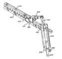
図1ないし12は、本発明の第1の実施例による巾着縫合装置を示す。 1 to 12 show a purse string suturing device according to a first embodiment of the present invention.
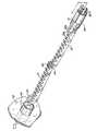
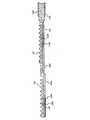
図1は本発明の巾着縫合装置の主要部分を示す。この装置は、主軸10、下方
ジョー12及び相補的な上方ジョー14を備える。下方ジョー12の手元側端部
は主軸10の端末に固定される。ジョー12、14は、巾着縫合の置かれる点で
管状組織を掴むように設計される。ヒンジ20が下方ジョー12の端末に固定さ
れ、ヒンジ22が上方ジョー14のヒンジ端に固定される。2個の比較的短い旋
回ピン24がヒンジ20、22の相補的に置かれた穴の中に差し込まれ、旋回中
心軸を確立する。取り付けられたとき、ピン24は、旋回中心軸の方向に沿って
間隔を空けられ、ピン間に空間を形成する。上方ジョーと下方ジョーとは、開口
位置と閉鎖位置との間で旋回中心軸まわりの平面円弧内で相対運動できる。開口
位置においては、上方ジョーは、閉鎖位置からほぼ181°から187°、より
好ましくは184°旋回される。上方ジョー14は、ヒンジ20、22上に設け
られた停止具により更に旋回することが防止される。FIG. 1 shows the main part of the purse string suturing device of the present invention. The device comprises a
下方ジョー12には、一様な大きさと間隔の1列の間隔を空けた歯16が設け
られる。上方ジョー14にも、間隔を空けられた相補的な歯18が設けられる。
歯18と歯16とは食い違いにされ、上方ジョーが旋回中心軸の周りで加工ジョ
ーと向かい合う閉鎖位置に旋回したとき、歯16は歯18と噛み合う(図6、7
及び8参照)。下方ジョー12の各歯16の頂部に溝26が形成される。各溝2
6は歯列の方向と平行に走る。断面においては、各溝は、底部、即ち溝が形成さ
れた歯の頂部から最も離れた位置に丸い部分、及び丸い部分から延びている長方
形部分又はスロットを含んだ鍵穴状に形成される。歯16の列の溝の丸い部分が
実質的に真っすぐな通路を形成するように整列され、この通路は歯の間の隙間に
より分割され又は分断される。上方ジョーの歯18には、平行な通路を形成する
ように同様な溝27が形成される。The lower jaw 12 is provided with
And 8). A groove 26 is formed at the top of each
6 runs parallel to the direction of the dentition. In cross-section, each groove is formed into a keyhole that includes a rounded portion at the bottom, i.e. farthest from the top of the tooth in which the groove is formed, and a rectangular portion or slot extending from the rounded portion. The rounded portions of the rows of
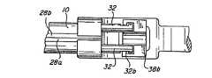
主軸10の周囲の12時の位置に形成された長手方向スロット10a内に、針
案内26aと26bとが置かれる。各針案内は細長い部材として押し出しプラス
チックで形成される。針案内26aの内面に長手方向の溝28aが形成される。
断面においては、溝28aは直線部分が跨ぐ2個の間隔を空けた半円形部分を備
える。針案内26bは同様な溝28bと共に案内26aの鏡像形に形成される。
溝28a、28bが互いに隣接して置かれるように、主軸10の長手方向スロッ
ト内で案内26a、26bが互いに接する。この方法で、溝28a、28bが組
み合って、直線溝により連結された2個の円形導管を有する「ドッグボーン」形
(メガネ形)の通路31(図9)を形成する。或いは、針案内をドッグボーン形
通路を有する一体型押し出し片として形成することができる。Needle guides 26 a and 26 b are placed in a longitudinal slot 10 a formed at the 12 o'clock position around the
In cross-section, the
The
針案内26a、26bは、案内の下半部が下方ジョー12と接し、又はその近
傍で整列して主軸10に取り付けられる。通路31の下方導管は下方ジョー12
の歯の溝26により定められる通路と揃えられる。上方ジョー14が閉鎖位置に
あるときは、案内26a、26bの上半部は上方ジョーと揃えられ、通路31の
上方導管は上方ジョーの歯の溝27により定められる通路と揃えられる。通路3
1の上方導管と下方導管との間の間隔は、ジョーの溝26と27とが完全に閉じ
られたときのこれらの間の間隔よりもわずかに大きくして、ジョーが完全閉鎖に
僅かに及ばないときに針が溝に確実に入るようにする。The needle guides 26a and 26b are attached to the
Aligned with the passage defined by the tooth groove 26. When the
The spacing between the upper and lower conduits of the one is slightly greater than the spacing between the jaw grooves 26 and 27 when they are fully closed, so that the jaws reach slightly closed. Make sure the needle enters the groove when not.
2個の傾斜した平面のカム斜面を有する分岐したカム部材30が、上方ジョー
14のヒンジ側端部と反対側の端部に設けられる。各カム斜面30aは各押し棒
32の掴み端部32aと組み合うことができる。押し棒32が作動されカム部材
30の方に強制されると、合成力は上方ジョー14を下方ジョー12と更に噛み
合わせる位置に下方に強制する。押し棒32は、主軸10の周囲の3時の位置と
9時の位置に設けられた細長いスロット10b内を摺動できる。A
針案内26a、26b及び押し棒32がそれぞれのスロット内に置かれた後で
、金属板製のばねバンド34が主軸10の周囲に嵌められ、案内と押し棒を保持
する。ばねバンドの隙間は、隙間の角度位置と無関係に、いかなる部材も滑り出
せないように十分に小さい。After the needle guides 26a, 26b and the
本発明は上述の形状には限定されない。上述の要素の多くの組合せを単一に形
成することが可能である。例えば、上方ジョー14、ヒンジ22、及びカム部材
30を一体に形成でき、主軸10、下方ジョー12及びヒンジ20、又は下方ジ
ョー12及びヒンジ20、等も同様である。The present invention is not limited to the shape described above. Many combinations of the above elements can be formed in a single unit. For example, the
図2及び3に示されるように、押し棒32は回転可能なレバー38により駆動
される。このレバーはハンドル36に関して回転可能であり、更にハンドル36
を通って設けられたピン40の周りで旋回可能である。このハンドルは握り部分
36aと連結部分36bとを備える。連結部分には穴が形成され、この中に主軸
10が置かれる。ハンドル36を主軸10に把持結合で固定するようにねじ44
が締められる。レバー38は、握り部分38a及び握り部分38aに関して実質
的に直角に曲げられた分岐したU字形部分38bを備える。U字形部分38bの
各アームはその内側にスロットを有し、押し棒32の手元側端部の切欠き32b
と組み合う。図4及び5参照。この切欠きはスロットの長さに沿って自由に動く
ことができ、その運動の全範囲を通じてU字形部分38bの角度方向の変化を受
け入れる。As shown in FIGS. 2 and 3, the
Is pivotable about a
Is tightened. The
Combine with. See FIGS. 4 and 5. This notch is free to move along the length of the slot and accepts angular changes in the
レバー38は、ばね42によりハンドル36から離れるように強制され、これ
により通常は押し棒32を後退させる。この配列により、使用者は、片手でハン
ドル36を掴みかつレバー38を絞ることができる。従って、使用者は、片手で
下方ジョー12と上方ジョー14との間の掴み圧力を効果的に制御できる。The
ラチェット歯を有する強固な固定用機構46がハンドル36の手元側端部に設
けられる。相補的なラチェット歯を有する回転可能な固定用機構48がレバー3
8の手元側端部に設けられる。レバー38がハンドル36に向かって絞られると
、回転可能な固定用機構48の歯は強固な固定用機構48の歯と順に噛み合って
いき、これによりハンドル36とレバー38の相対位置を固定する。回転可能な
固定用機構48は、押し棒32を後退させるために、強固な固定用機構46との
噛み合いを外して回転されハンドルとレバーとの固定を解除する。A
8 is provided at the proximal end. When the
1本の生体吸収可能な単繊維縫合糸58の各端部が針56の先端56aに取り
付けられる。針の直径は、針案内26a、26bの円形導管及び歯の円形通路を
通って摺動するに十分に細いが、円形導管及び通路からの滑り出しを防ぐに十分
な太さである。先端56aを折り取れるように、針56の先端と主体部とが出会
う位置にノッチ56cを設けることができる。各針の手元側端部56bは押し又
は引く力を受けるために直角に曲げられる。縫合糸58は、歯の溝26、27の
スロットの幅、及びドッグボーン通路30の真っすぐな溝の幅より小さい直径の
ものである。Each end of one bioabsorbable
本発明の縫合装置を使用した管状組織の巾着縫合の形成方法が、以下詳細に説
明されるであろう。A method for forming a purse string suture of tubular tissue using the suturing device of the present invention will be described in detail below.
最初に、本発明の巾着縫合装置が、例えば腹壁52に挿入された小さなカニュ
ーレ54を経て挿入される。カニューレ54の直径は、例えば12mm台であり、
かつ下方ジョー12と上方ジョー14とが開かれた位置にあるときにこれを内部
に挿入し得るような大きさにされる。しかし、ジョーが閉じた位置にあるときは
、カニューレはジョーが入り得るのには小さすぎる。また、カニューレは、主軸
10がハンドル36とのその連結部まで入り得るに十分な大きさである。従って
、本装置の挿入には身体の小さな開口を必要とするだけである。Initially, the purse string suturing device of the present invention is inserted through a
And when the lower jaw 12 and the
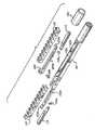
図2を参照すれば、ジョーが開口位置にある状態の縫合装置の端末が、縫合さ
れる管状組織の付近でカニューレ54内に挿入される。開口位置においては、先
行の上方ジョー14は、下方ジョー12に対してある角度、例えば184°にあ
る。従って、カム部材30のある上方ジョー14は、ある角度で挿入される。こ
れにより、カム部材30をより高く形成でき、これが押し棒32のカム端部に従
動するより大きな輪郭を与える。また、ジョーはこの角度において運動を限定さ
れ停止されるので、この角度での挿入の際は不注意でジャックナイフのように閉
鎖位置に戻ることが少ない。Referring to FIG. 2, the end of the suturing device with the jaws in the open position is inserted into the
縫合装置の末端が完全に挿入されると、図6に示されるように、下方ジョー1
2を下方位置として縫合すべき管状組織を横切る。第2のカニューレ(図示せず
)を通して鉗子57が挿入され、上方ジョー14を掴み、管状組織がジョーの間
にある状態で上方ジョーを閉鎖位置に回転させる。次いで、鉗子57を使用して
、図7に示されるように、カム部材30のカム斜面30aが、押し棒32のカム
面32aと揃うようにカム部材30を下方に押す。揃ったときに、レバー38が
絞られ、押し棒32を前進させる。押し棒が前進すると、カム面32aがカム斜
面30aと接触し、図8に示されるようにカム部材30と上方ジョー14とを下
方に強制する。こうして、管状組織50は希望の大きさの力で上方ジョーと下方
ジョーとの間に掴まれ、これが固定用機構46、48の歯の相互組合いにより維
持される。When the end of the suturing device is fully inserted, as shown in FIG.
Cross the tubular tissue to be sutured with 2 as the lower position.
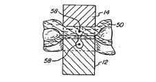
ジョーが希望の大きさの力で管状組織を掴むと、対向した歯列16、18がこ
れらの間の組織50を波状に曲げる。図8に示されるように、組織50の管は潰
され、各歯の頂部に組織の2個の管壁が重なる。When the jaws grasp the tubular tissue with the desired amount of force, the opposing
このとき、縫合糸58の端部に各が取り付けられた針56が、針案内26a、
26bにより定められた通路30の円形導管内に差し込まれ、ジョー12、14
の歯16、18に形成された溝26、27により定められた通路を通る。各針が
ジョーの歯から歯に移動すると、針は他方のジョーと接触している組織の管壁を
貫くことなしに、このジョーと接触している組織の管壁を刺す。この方法で、各
針は、管を閉鎖するように縫うことなく組織の2個の管壁の一方に縫合糸を通す
。縫合糸の端部が導管及び通路を通って進むとき、縫合糸を連結している輪は、
ドッグボーン形通路30のスロットを自由に通過できる。針がヒンジピン24の
間を通過するので、ピン24が針の前進を妨害することはない。縫合糸58の端
部を伴った各針の先端56aがジョーの端末から出た後で、管状組織の管壁にこ
れを囲んだ一連の縫い目が形成されるであろう。At this time, the
26b is inserted into the circular conduit of the
Through a passage defined by grooves 26 and 27 formed in the
It can freely pass through the slot of the dogbone-shaped
もし針56に破断しうるノッチ56cが設けられているならば、第2のカニュ
ーレを通じて操作される鉗子により各針の端部を折り取ることができる。次いで
、針の残りの部分が通路を通して引き戻される。組織は、これを閉鎖されたジョ
ーの一方の側、又は他方の側で切断することができる。その後、固定用機構が解
放され、上方ジョーが開口位置に旋回され、第1のカニューレ54を通して縫合
装置が引き抜かれる。ジョーが管状組織から取り去られると、縫い目は、歯に形
成された溝26、27のスロットを通って自由に通り抜けられる。その後で、管
状組織の端部が吻合リング又は類似物の上に置かれ、次いでリング上で巾着縫合
にきちんと引かれ、通常の方法で結ばれる。If the
針が破断可能でないときは、まず、縫合糸の各端部に輪を作るように針が少し
引かれる。これらの輪が切られ、縫合糸の自由端は鉗子により掴まれる。次に、
針全体が引かれ、縫合装置は上と同じ方法で取り出される。When the needle is not breakable, the needle is first pulled slightly to create a loop at each end of the suture. These rings are cut and the free end of the suture is grasped by forceps. next,
The entire needle is pulled and the suturing device is removed in the same manner as above.
図13ないし26は、本発明の第2の実施例による巾着縫合装置を示す。 13 to 26 show a purse string suturing device according to a second embodiment of the present invention.
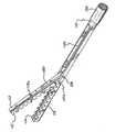
図13は本発明の巾着縫合装置の主要部分を示す。この装置は、主軸110、
第1のジョー112及び相補的な第2のジョー114を備える。第1のジョー1
12は支持梁120を経て主軸110に連結され、図14に示されるように、こ
れは主軸の旋回中心軸128の周りで回転可能である。第2のジョー114は支
持梁110bに固定され、図14に示されるように、この支持梁は主軸110の
端末に一体に形成される。ジョー112、114は、巾着縫合が置かれる点にお
いて管状組織を掴むように設計される。FIG. 13 shows the main part of the purse string suturing device of the present invention. This device comprises a
A
12 is coupled to the
図14に明らかなように、第1のジョー112には、一様な大きさ及び間隔の
1列の間隔を空けた歯116が設けられる。第2のジョー114にも、間隔を空
けられた相補的な歯118の列が設けられる。歯118と歯116とは食い違い
にされ、第1のジョーが旋回中心軸128の周りで第2のジョーと向かい合う掴
み位置(閉鎖位置)に旋回されたとき、歯116は歯118と噛み合う。第1の
ジョー112の各歯116の頂部に溝116aが形成される。各溝116aは歯
列の方向と平行に走る。断面において、各溝は、その底部、即ち溝が形成された
歯の頂部から最も離れた位置の丸い部分、及び丸い部分から歯の頂部に延びてい
る長方形部分又はスロットを含んだ鍵穴状に形成される。歯116の列の溝の丸
い部分は実質的に真っすぐな通路を形成するように整列され、この通路は歯の間
の隙間により分割され又は分断される。第2のジョーの歯118には、平行な通
路を形成するように、同様な溝118aが形成される。As can be seen in FIG. 14, the
図13に示されるように、1本の生体吸収可能な単繊維縫合糸162の各端部
が針160の先端160aに取り付けられる。針の直径は、歯の溝116a、1
18aの円形通路を通って摺動するに十分に細いが、通路からの滑り出しを防ぐ
に十分な太さである。先端160aを折り取れるように、針160の先端と主体
部とが出会う位置にノッチ160cを設けることができる。縫合糸162は、歯
の溝116a、118aのスロットの幅より小さい直径のものである。As shown in FIG. 13, each end of a single bioabsorbable
It is thin enough to slide through the circular passage 18a, but thick enough to prevent slipping out of the passage. A
図14ないし19を参照すれば、各ジョーは、それぞれ支持梁120、110
bにピン113a、115b周りで回転可能に取り付けられ、かつジョーを各梁
の平らな部分120a、110aにジョーを押し付けるヘヤーピン状の板ばね1
13、115により、支持梁に押し付けられ保持される。Referring to FIGS. 14-19, each jaw has a
a spring pin-shaped
13 and 115 are pressed against and held by the support beam.
図13においては、ジョーは、閉鎖位置(掴み位置)において示される。ジョ
ーは、ジョー支持梁110b、120上に乗っているスリーブ130の作用によ
り押され閉鎖される。スリーブ130は摺動管であり、2個のジョー支持梁11
0b、120間でカム作用を生じてジョー112、114を一緒に絞る位置へ、
軸110に沿って端末方向に動くことができる。或いは、ジョーと梁との組立体
が後退したときに、隠れていた部分110cを露出させるように手元側に軸に沿
って動き得る。スリーブの端部付近の広げられたフランジ領域130aは、スリ
ーブの手元側端部の一体部品として内側に固定された気密ダイヤフラム(図示せ
ず)を備える。プッシャー136のフォーク状の端部136aと組み合うように
、スリーブのフランジ領域に溝130bが設けられる。溝130bとプッシャー
136のフォーク状端部136aとの間には十分な隙間があり、従ってプッシャ
ーは、ピン146において旋回側端部を軸110に向け又はこれから離すように
、フォークを溝の中で拘束することなしに合理的な距離を運動させることができ
る。上述のダイヤフラムは軸110に対する気密を提供する。縫合装置が挿入さ
れるカニューレにも、気密具としてスリーブ130を払拭するダイヤフラムを設
けるべきである。これは縫合手術中の加圧された腹部からの漏洩を防止する。In FIG. 13, the jaws are shown in the closed position (gripping position). The jaws are pushed and closed by the action of the
To the position where the cam action is generated between 0b and 120 and the
It can move in the terminal direction along the
再び図13を参照すれば、ハンドル132は、例えばピン144又は把持具に
より主軸110の手元側端部に固定される。レバー134がピン142によりハ
ンドルに旋回可能に取り付けられる。レバー134は、ピン146によりプッシ
ャー136に連結され、レバーが静止ハンドル132の限定停止具、即ちハンド
ル取付け用ピン144に達するまでばね140により強制され開かれ、これによ
り通常はプッシャー136を経て管130を後退させている。この配列により、
使用者は片手でハンドル132を掴みレバー134を絞ることができる。従って
、使用者は、片手で第1のジョー112と第2のジョー114との間の掴み圧力
を効果的に制御できる。Referring to FIG. 13 again, the
The user can grasp the
ラチェット歯を有する強固な固定用機構132aがハンドル132の手元側端
部に設けられる。相補的なラチェット歯を有する回転可能な固定用機構138が
レバー134の手元側端部に設けられる。レバー134がハンドル132に向か
って絞られると、回転可能な固定用機構138の歯は、強固な固定用機構132
aの歯と順に噛み合っていき、これによりハンドル132とレバー134の相対
位置を固定する。プッシャー136及び管130を後退させるためには、回転可
能な固定用機構138が強固な固定用機構132aとの組み合いを外して回転さ
れ、ハンドルとレバーとの固定を解除する。A strong fixing mechanism 132 a having ratchet teeth is provided at the proximal end of the
The teeth a are sequentially engaged with each other, and thereby the relative position between the
フォーク状のプッシャー136がレバー134の頂部に旋回可能に取り付けら
れ、ハンドル132に向かうレバーの絞りが、スリーブ130をジョー支持梁1
10b、120上の前述のカム作用位置に駆動する。プッシャーのフォーク状端
部136aはスリーブ130の手元側端部の溝130b内に適合し、従ってスリ
ーブはレバー112の運動に指示されたいずれの方向にも駆動される。プッシャ
ーのフォーク状端部136aは、スリーブ130の端部の溝130bとの組合い
から外れて上方に旋回でき、スリーブは、図14に示されたように、ジョーを収
納するに要する長さの距離を工具の手元側端部に向かって動くことができる。A fork-
Drive to the aforementioned cam action position on 10b, 120. The fork end 136a of the pusher fits in the
頑丈なプッシュプル棒148が軸110の中央を通って伸びる。プッシュプル
棒148はその手元側端部にノブ150を有し、これにより使用者はこれを作動
させることができる。プッシュプル棒は、図20に特に示されるような軸の内側
のケーブル148aに連結される。このケーブルの目的は、支持梁120をこの
梁が支持するジョー112と共に回転させることであり、この回転により支持梁
はスリーブ130と作用する中間部分に位置決めされ、更に巾着縫合術後にスリ
ーブ130が入れ子部分110cを塞がないように十分に後退させられたとき、
前記回転がこの組立体を軸110の入れ子部分110c内に後退させる。A sturdy push-
The rotation causes the assembly to retract into the nested
図14において、旋回可能の支持梁120及びこれが支持するジョー112は
、ピン128の周りを軸110の入れ子部分110c内に旋回させられている。
ジョーは、カニューレ(図示せず)を通って出入するときはこの位置に留められ
る。スリーブ130は、図示のようにジョー112が入ったときのその最も後退
した(手元側)位置において示される。強度のため、及び使用されるカニューレ
の細い内径に対してジョーに要求される大きさのため、スリーブ130は、ジョ
ー112の上方に適合するようには設計されないが、カニューレの通過には適す
るように設計される。最末端のジョー114は、主軸110の部分である非回転
支持梁110bの梁の端部にある。この状態においては、ジョー及びその支持梁
は比較的小直径のカニューレを通って挿入できる。最手元側のジョー112(カ
ニューレを通過する最後のジョー)がカニューレを通過し終わると、以下更に説
明されるようにケーブル148aを進めるようにノブ150を押すことにより、
このジョーはその支持梁120と共に旋回して凹所又は入れ子部分110cから
出てピン128の周りで旋回する。ピン128は軸110と支持梁120とを通
る横断方向の中心軸を有し、従ってジョー112が回転させられる。この回転は
、支持梁とジョー112とが他方のジョー114の付近にきてこれと接触するま
で、又はこれに対して閉じるまで続く。In FIG. 14, the
The jaws remain in this position when entering and exiting through a cannula (not shown). The
This jaw pivots with its
再び図15、16、17及び18を参照すれば、軸110は、手元側端部の円
柱状本体、端末のジョー支持梁110b、及び凹所110cのある入れ子部分を
囲んだ一体部材であり、更にこの凹所はジョー112と支持梁120とが装置の
想像中心線上で十分に後退し入れ子となりうる長さを有する中間部であり、従っ
て組立体が小直径カニューレの通過に適合できることに注意すべきである。更に
、凹所110cは軸110を完全に通過して切り取られ、従って行き止まりのポ
ケット部が形成されず、このため、この入れ子部分には物質が停滞せず、カニュ
ーレを通じての装置の取り出しの前にジョー/梁の組立体のこの入れ子部分内へ
の旋回を妨げないことにも注意すべきである。凹所110cの殻110dは、ジ
ョー112が凹所110c内に後退したときのこのジョーのための停止部として
作用する。これにより、ジョーは最小の全体寸法で定位置に確実に収められる。
凹所110cの部分に沿った軸110の外面は、これらの図面では便宜上平坦で
示したが、実際は、要求されるように切取り部分110c及び110dにより中
断された旋回ピン128までの同一円筒状軸の延長部とすることができる。Referring again to FIGS. 15, 16, 17 and 18, the
The outer surface of the
図19を参照すれば、ジョー112、114を支持梁110b、120に押し
付けて保持しているヘヤーピン状ばね113、115が示される。このヘヤーピ
ン状ばねは、リベット113b、115bによりそれぞれのジョーに永久固定さ
れる。ヘヤーピン状ばねは、もし拘束されていなければ図示されたものより更に
閉じた位置に戻ることが通常であるように形成され、この方法で、これらのばね
は常に支持梁に対してばねによる強制力を与える。旋回ピン113a、115a
はそれぞれのジョーに永久固定されかつ十分に突き出し、従って、更にジョーが
その支持梁に関して回転したとき、回り止の移動は克服され、かつ支持梁がピン
端部から滑り出す危険がない。各ヘヤーピン状ばねは、その旋回ピンの周りに隙
間のある穴を使用するがその位置の確立にはピンを使わない。従って、各ヘヤー
ピン状ばねは、旋回ピンの端部を完全に離れて撓むことができ、支持梁に力を加
え続ける。旋回ピン113a及び115aは、組立体のその他の部分と共にカニ
ューレの通過にちょうど適合する合理的な長さに限定される。Referring to FIG. 19, there are shown
Is permanently fixed to each jaw and protrudes sufficiently so that when the jaw is further rotated with respect to its support beam, the detent movement is overcome and there is no risk of the support beam sliding out of the pin end. Each hairpin spring uses a hole with a gap around its pivot pin but does not use a pin to establish its position. Thus, each hairpin spring can deflect completely away from the end of the pivot pin and continue to apply force to the support beam. The pivot pins 113a and 115a are limited to a reasonable length that just fits the cannula passage along with the rest of the assembly.
図18に見られるように、各ジョーの下側は角度の付けられた壁112b,1
14bを有し、これらは一線の回り止溝を描く。挿入中、各支持梁はヘヤーピン
状ばねの力により回り止溝の中に保持されるので、ジョーはそれぞれの支持梁と
平行に置かれる。ジョーを作動位置に動かすために、各ジョーに外力を加え回り
止力を克服しかつジョーをそれぞれの支持梁に関してある角度で回転させる。こ
のとき、ばね力は各ジョーの下側の平らな隆起を支持梁の平面110a、120
aに対して同一面に保持するであろう。As seen in FIG. 18, the underside of each jaw is an
14b, which draw a line of detent grooves. During insertion, each support beam is held in the detent groove by the force of the hairpin spring, so that the jaws are placed parallel to the respective support beam. To move the jaws to the operating position, an external force is applied to each jaw to overcome the detent force and rotate the jaws at an angle with respect to the respective support beam. At this time, the spring force causes the flat ridges on the lower side of the jaws to support the
will be held flush against a.
さて、図20を参照すれば、回転可能な支持梁120に取り付けられたピン1
20cに取り付けられた可撓性部材としてケーブル148aが示される。このピ
ン120cは、ケーブルによりピン120に対して加えられる押し又は引きの作
用が支持梁120をジョー112と共に旋回ピン128の周りで回転させるよう
に、旋回ピン128に関して位置決めされる。この方法で、梁及びジョーの組立
体を、軸110を入れ子部分に出入させるために遠隔的に旋回させることができ
る。ケーブル148aは、これがプッシュプル棒148と結合するまで軸に沿い
、又は軸を通って移動する。ケーブルを、これに加えられた軸方向の力に応答し
かつ適正に撓むように、ケーブルを座屈しないように保持しかつピン120への
適正な方向の力を与えさせるために、計画的に位置決めされた拘束具が必要であ
る。この拘束部は、典型的には、ジョー入れ子凹所110cの底部において軸1
10を架橋するブリッジ110e、110fの形式である。Now, referring to FIG. 20, the
Cable 148a is shown as a flexible member attached to 20c. This
10 is a
本発明の縫合装置を使用した巾着縫合の形成手順が以下詳細に説明されるであ
ろう。The procedure for forming a purse string suture using the suturing device of the present invention will be described in detail below.
最初に、本発明の巾着縫合装置が、例えば腹壁に挿入された小さなカニューレ
を経て挿入される。カニューレ(図示せず)の直径は、例えば10mm台であり、
かつ縫合装置が(開かれた)挿入位置にあるときに第1のジョー112と第2の
ジョー114とを内部に挿入し得るような大きさにされる。しかし、ジョーが(
閉じた)掴み位置にあるときは、カニューレはジョーが入り得るのには小さすぎ
る。また、カニューレは、スリーブ130を含んだ主軸110が拡大フランジ部
分130aまで入り得るに十分な大きさである。従って、本装置の挿入には身体
の小さな開口を必要とするだけである。Initially, the purse string suturing device of the present invention is inserted, for example, through a small cannula inserted in the abdominal wall. The diameter of the cannula (not shown) is, for example, on the order of 10 mm,
And sized so that the
When in the gripped position, the cannula is too small for the jaws to enter. The cannula is also large enough to allow the
ジョーが開口位置にある状態の縫合装置の端末が、縫合される管状組織の付近
でカニューレ内に挿入される。開口位置においては先行のジョー114は、ジョ
ー112に対してある角度、実質的に180°にある。The end of the suturing device with the jaws in the open position is inserted into the cannula near the tubular tissue to be sutured. In the open position, the leading
工具がカニューレを通して十分に挿入され、最も手元側のジョー112(カニ
ューレを通過する最後のもの)がカニューレを通り抜けると、手術者によりノブ
150が押され、これにより、梁120及びジョー112の組立体は、図21に
示されたように、その最も手元側位置(挿入位置)から他方のジョー114に向
かい端末寄り位置(中間位置)に回転させられる。組立体は、軸110と支持梁
120とを通る横断方向中心軸を有するピン128の周りを旋回する。When the tool is fully inserted through the cannula and the most proximal jaw 112 (the last one that passes through the cannula) passes through the cannula, the surgeon pushes the
次に、図22を参照すれば、ジョー112と114とは、プローブの鉗子(図
示せず)のような適宜のその他の別に導入された工具の使用により掴まれ、梁1
10b、120を中央に維持している角度付きの縁を越え、ばねで押さえられた
回り止位置から外れて側方外向きにひねられる。両方のジョーは同じ方向及び角
度にひねられる。この段階では、ヘヤーピン状ばねにより与えられる力により、
支持梁端部110a及び120aの端部の角度付きの平面と、各ジョーの2個の
背後の最も隆起した頂部により現される平面とが押し付けられ保持される。Referring now to FIG. 22,
Beyond the angled edge maintaining 10b, 120 in the center, it is twisted laterally outward away from the detent position held by the spring. Both jaws are twisted in the same direction and angle. At this stage, due to the force applied by the hairpin spring,
The angled planes at the ends of the support beam ends 110a and 120a and the planes represented by the two most raised peaks behind each jaw are pressed and held.
図23、24、25及び26を参照すれば、各が軸110に対してある角度、
典型的には45°にひねられたジョー112、114は、完全に掴むための機能
的な位置又は準備位置にある。Referring to FIGS. 23, 24, 25 and 26, each is at an angle with respect to
The
工具は、ジョー112、114が縫合すべき組織(図示せず)上に希望のよう
に置かれるようにひねられ、位置決めされる。次いで、軸110上でスリーブ1
30が手で滑り降ろされ、これが支持梁110b、120上に達するまで滑り続
ける。スリーブは、その最手元側端部を軸上におき、かつその末端を予め入れ子
にされたジョー112がちょうど明らかにされた状態で予め位置決めされる。ス
リーブは、手で押してこの位置に動かされるとき、2個の気密のゴムダイアフラ
ムの摩擦だけを克服しなければならない。ダイアフラムの一方はスリーブを軸に
対して封鎖し、もう一つはカニューレを軸に対して封鎖する。次に、レバー13
4がプッシャー136の旋回により定位置に組み合わせられ、プッシャー136
のフォーク状端部136aがスリーブ130の溝130bと組み合う。The tool is twisted and positioned so that the
30 is slid down by hand and continues to slide until it reaches the support beams 110b, 120. The sleeve is pre-positioned with its most proximal end on the axis and its end
4 is combined into a fixed position by turning the
The fork-shaped end portion 136a is combined with the
ここで、巾着縫合用掴みジョーによる組織の最終閉鎖の進行が準備される。レ
バー134がハンドル132に関して絞られ、フォーク状のプッシャー136が
所望の力でスリーブ130を押す。固定用機構132a、138の歯が噛み合い
、レバーを所望の位置及び掴み圧力に保持する。ジョーのピン113a、115
aによる支持梁の旋回取り付けがピンの周囲の僅かな量の隙間を許し、従ってジ
ョーは、組織の不規則な形の潰れの上を絞るとき自己水準化をする。Here, the progression of the final closure of the tissue by the purse string suturing jaws is prepared. The
The pivoting mounting of the support beam by a allows a small amount of clearance around the pin, so the jaws are self-leveling when squeezing over an irregularly shaped collapse of the tissue.
掴み位置に接近するとジョーの下側を支持している支持梁110b、120の
平坦部110a、120aの面が平行になるので、ジョーは互いに面と面とが平
らな状態に達するであろう。ジョーが、梁の回り止作用を解除するに十分に少な
くも約30°ひねられ又は角度を付けられる限り、梁回り止作用がその他の極限
のひねりにおいて達せられるまでは、ジョーが適宜の別の角度に回転された場合
でも、上述の類推が生ずるであろうということに注意すべきである。これは、ジ
ョーの下側が梁の平坦部に乗るようにジョーが十分にひねられた後に、これらは
ほぼ120°の相補的位置に達するまでのどの角度においても効果的に機能する
ことができるということを意味する。ジョーがひねられて、梁/溝の回り止シス
テムを外し、かつそれらの下側が梁の角度付き平坦部の上に乗るまで、ジョーは
互いに平坦部を閉じられないことに注意すべきである。When the gripping position is approached, the surfaces of the
ジョーが所望の大きさの力で管状組織を掴むと、歯116、118の対向した
列がこれらの間の組織を波状に曲げる。組織の管が潰されるので、組織の2個の
管厚が各歯の上に重なる。When the jaws grasp the tubular tissue with the desired amount of force, the opposing rows of
巾着縫合装置が組織の所望部位に置かれ又は把持されたとき、それぞれが縫合
糸162の端部に取り付けられた針160が、ジョー112、114の歯116
、118に形成された溝116a、118aにより定められた通路内に差し込ま
れる。各針は、一方のジョーの歯から歯へと移動してこの壁と接触している組織
の管壁を刺し、他方のジョーと接触する組織の管壁を貫くことはない。この方法
で、各針は、組織の2個の管壁の一方の管壁に縫合糸を通し、管を閉じるように
縫うことはしない。両方の針を同時に刺すことは必要でない。縫合糸162の端
部を有する各針の先端160aがジョーの端末から現れた後に、一連の囲んだ縫
い目が管状組織の管壁に形成されるであろう。When the purse string suturing device is placed or grasped at a desired site in the tissue, the
, 118 are inserted into the passages defined by the
もし針160に破断しうるノッチ160cが設けられているならば、例えば、
第2のカニューレを通じて操作される鉗子により各針の端部160aを折り取る
ことができる。次いで、針の残りの部分が通路を通して引き戻される。組織は、
閉鎖されたジョーの一方又は他方の上でこれを切断できる。If the
The end 160a of each needle can be broken by forceps operated through the second cannula. The rest of the needle is then pulled back through the passage. The organization
This can be cut on one or the other of the closed jaws.
針が破断可能でないときは、まず、縫合糸の各端部に輪を作るように針が少し
引かれる。これらの輪は切られ、縫合糸の自由端は鉗子により掴まれる。次に、
針全体が引かれ、縫合装置は上と同じ方法で取り出される。When the needle is not breakable, the needle is first pulled slightly to create a loop at each end of the suture. These rings are cut and the free end of the suture is grasped by forceps. next,
The entire needle is pulled and the suturing device is removed in the same manner as above.
巾着縫合装置を取り出すには、レバー134が解除され、フォーク状プッシャ
ー136をスリーブスロット130bとの組合いから外し、更にスリーブ130
をその最も手元側位置に後退させなければならない。次いで、ジョーをそれらの
支持針との回り止整列位置にひねり戻さねばならない。次に、ノブ150を引き
戻し、梁120とジョー112との組立体を軸110の凹所110c内に戻すこ
とによりこれを後退させる。このとき、組立体は、ジョー112がずっと旋回し
て戻りうるに十分までまだカニューレを通って差し込まれたままである。ここで
カニューレを通して工具を引き抜くことができる。To remove the purse string suture device, the
Must be moved back to its most proximal position. The jaws must then be twisted back into the detent alignment position with their support needles. Next, the
図27ないし32、34及び35は、本発明の巾着縫合装置の第3の実施例を
示す。27 to 32, 34 and 35 show a third embodiment of the purse string suturing device of the present invention.
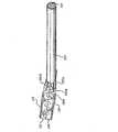
まず図27及び28を参照すれば、この縫合装置は、第1のジョー210及び
第1の旋回中心軸の周りを旋回運動できるように、旋回ピン214により連結さ
れた第2のジョー212を備える。各ジョーは、一様な大きさで一様に間隔を空
けた1列の歯216を持つ。歯は、第1及び第2の実施例に関連して上述された
歯と同じ形状にされ、かつ同じ方法で歯の間に組織を掴むように作用する。Referring first to FIGS. 27 and 28, the suturing device includes a
図28に示されるように、第2のジョー212は、カムロッド220と当たる
カム面218をその手元側端部に備える。更に、第2のジョーは、針カートリッ
ジを受け入れる湾曲した通路222、及び以下詳細に説明される方法で限界ピン
を受け入れるノッチ224を持つ。As shown in FIG. 28, the
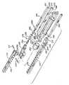
第1のジョー210はその手元側端部に延長部226を有し、この延長部は、
第1の旋回中心軸と平行な第2の旋回中心軸周りの旋回運動ができるように、旋
回ピン214によりトグル又は空転レバー228に連結される。空転レバーは第
1の連結具234とリンクピン236とによりリンク232に連結される。リン
ク232は、第2の連結具240とリンクピン242とにより駆動ロッド238
にも連結される。認められるように、各連結具234及び240は円柱状の一端
を持つ。これにより、リンク232は、両リンクピンまわりに旋回すると共にそ
の長手方向中心軸まわりに回転できる。The
The
Also connected to. As will be appreciated, each
細長い軸244がそれぞれ細長いスロット246及び248内のカムロッド2
20及び駆動ロッド238を摺動可能に収容する。軸(及びカムロッドと駆動ロ
ッド)の長さは任意であるが、一般に図28に示されたものよりは長い。軸24
4の端末には大きな穴250と小さな穴252とがある。関節接合ピン254が
大きな穴250を通り第2のジョー250の同寸法の穴256内に延び、これに
より、カムロッド220がカム面218を押したときに、連結されたジョーの対
は、第1の旋回中心軸と直交する第3の旋回中心軸まわりに旋回できる。限界ピ
ン258が小さな穴252を通って延び、第2のジョーのノッチ224内で摺動
できる。限界ピンはノッチの閉じた端部に当たり、第3の旋回中心軸まわりの反
時計方向のジョーの関節運動を制限する。軸の下側に突起(図示せず)があり、
これが第2のジョーのカム面と当たり、ジョーが軸と軸方向で一線になる位置へ
のジョーの第3の旋回中心軸まわりの時計方向運動を限定する。軸は、以下説明
されるように針案内又はカートリッジ262を摺動可能に受け入れる細長いスロ
ット260を備える。カムロッド、駆動ロッド及び針案内を細長い軸のそれぞれ
のスロット内に収容するように、バンド264が軸上でその細くされた部分26
6に滑る。
20 and drive
4 has a
This hits the cam surface of the second jaw and limits the clockwise movement of the jaw about the third pivot center axis to a position where the jaw is axially aligned with the axis. The shaft includes an
Glide to 6.
針カートリッジ262は、可撓性材料、例えば適切なポリマープラスチックで
作られ、かつその細長い本体を通って軸方向に延びる開口268を持つ。この開
口は、2本の外科用針及び閉鎖ループを形成するように各端において針の一つに
連結された生体吸収可能な外科用縫合糸を受け入れるように設計される。従って
、この開口は溝272で結ばれた2個の円形部分270を有する実質的にドッグ
ボーン形の断面を持つ。外科用針は円形断面の各の中に装填される。認められる
ように、溝は、針がそれぞれの円形部分から横方向に外れずに滑り得るように針
の直径より小さな幅を有するように設計される。以下詳細に説明されるように、
針が開口内を軸方向に移動すると、外科用縫合糸はこの溝を通過することにより
針に追随する。
As the needle moves axially through the opening, the surgical suture follows the needle by passing through the groove.
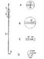
本発明の外科用縫合装置の開示された3種の実施例に好ましく使用される外科
用針が図33に詳細に示される。この針は、細長い針軸274及び破断しうる頸
部278により一緒に連結された尖った針頭276を備える。針軸274の手元
側端部は、使用者が針カートリッジと組織とを通して針を押すことを助けるため
に角度付きの部分280を持つ。針を押すためのその他の手段、例えば針軸の端
部上のプラスチックキャップも予想される。破断可能な頸部は、部分図33Aに
示された、例えば90°のノッチを形成するように角度を付けられた2個の角度
部分278、280で形成された小直径部分を持つ。小直径部分は、縫合糸が組
織を縫った後における針頭と縫合糸との針軸からの切離しを容易にするために設
けられる。The surgical needle preferably used in the three disclosed embodiments of the surgical suturing device of the present invention is shown in detail in FIG. The needle includes an
針頭に外科用糸を固定する方法の一つは、部分図33Cに示されるように、糸
を受け入れるために針頭に長手方向のスロット284を設けることである。糸の
周囲でスロットを圧縮させるように針頭を静かに縮らせる。この外科用針の別の
特徴は長手方向の溝286であり、これは、図33B及び33Cに示されるよう
に、スロットから延びて針軸に沿って連なる。長手方向の溝(及びスロット)は
外科用糸よりも大きい寸法にされ、従って糸は針の全体周囲寸法を増すことなし
に溝内に適合できる。この方法で、針と各ジョーの歯列の針通路との間に非常に
狭い許容差を維持できる。従って、溝の長さは少なくも針通路の長さとすべきで
ある。One method of securing the surgical thread to the needle head is to provide a
外科用針の尖った端部に、針の尖端290から半径方向外向きに延びている切
断用の刃288を設けることもできる。部分図33Dは互いに120°の等間隔
に置かれた3個の切断刃288を示す。切断用の刃は、針が組織を通って移動す
るとき組織を切断する。A
図34及び35は、掴み用ロッド220及び駆動用ロッド238を操作するた
めのハンドル組立体の1形式を示す。この組立体は、細長い軸244の手元側端
部に固定されたL字形ハンドル292を備える。しかし、便宜上、このハンドル
組立体に連結されたカムロッド220及び駆動用ロッド238のみしか示されな
い。絞り得るL字形のアクチュエーター294が、旋回ピン296によりハンド
ル292に旋回できるように取り付けられ、かつばね298により上方位置又は
開口位置に強制される。アクチュエーターはピン300により駆動用ロッド23
8に連結され、アクチュエーターがハンドルの方に絞られたときに駆動用ロッド
を前方に滑らせる。ハンドルの下側に旋回停止部材302が取り付けられ、アク
チュエーターの受けピン304と組み合い、ジョーを閉鎖するがきつく掴まない
位置に駆動用ロッドの摺動を停止させる。(図34及び35の両図に示されるよ
うに)受けピンが組み合わないように停止部材が旋回して定位置から外れると、
アクチュエーターは、駆動用ロッドを後退させジョーを開くように完全上方位置
に強制される。揺動可能な固定用部材306がハンドルの手元側端部に旋回可能
に取り付けられ、図35に示されたようにアクチュエーターのノッチ308と組
み合うように上方に揺動することができる。回転可能なノブ310が締められ、
アクチュエーターをその絞られた位置又は閉鎖された位置に固定し、ジョーをき
つく掴むことができる。FIGS. 34 and 35 show one type of handle assembly for manipulating the
8 and slides the drive rod forward when the actuator is squeezed towards the handle. A
The actuator is forced to the fully up position to retract the drive rod and open the jaws. A
The actuator can be fixed in its squeezed or closed position and the jaws can be gripped tightly.
ピン314によりカムロッド220に摺動スプール312が取り付けられる。
このスプールは、ハンドルから延びているロッド316に沿って滑り、カムロッ
ドを前後に作動させる。ロッド316の手元側端部にはねじが設けられ、更に摺
動スプールをその最前方位置に固定するように締め得る固定用ナット318を備
える。A sliding
The spool slides along a
使用の際は、この縫合装置は、図27に示されるようにジョーを閉鎖しかつ細
長い軸と軸方向で一線に揃えられて、例えば12mmのカニューレにより身体内に
差し込まれる。この状態にするために、カムロッドをできるだけハンドルの方に
後退させ、駆動用ロッドはジョーを閉じるように引かれてジョー閉鎖位置(ここ
でアクチュエーター294上の限定ピン304がハンドル308の停止レバー3
02と当たる)にほとんど戻される。In use, the suturing device is inserted into the body with a 12 mm cannula, for example, with the jaws closed and axially aligned with the elongated shaft as shown in FIG. To achieve this condition, the cam rod is retracted as far as possible toward the handle, and the drive rod is pulled to close the jaws and the jaw closed position (where the limiting
Almost hit back to 02).
外科用装置がカニューレを通して挿入された後に、ハンドルのロッド316に
沿ったスプール312の滑りによりカムロッドが前方に摺動される。この作用に
より、カムロッドの端末が第2のジョーのカム面218と当たり、第1のジョー
と第2のジョーを作動ピン254の周りで関節接合運動、又は旋回させる。ジョ
ーは、これがスプールに当たるまでロッドの固定用ナット318の回転により図
29に示された関節接合運動位置に固定される。ジョーを関節接合位置又は角度
位置に置くことの利点は、掴まれる組織の部分の良好な観察を外科医−使用者に
提供することである。この装置の別の利点は、体腔を横切る角度付けによる接近
性の提供である。After the surgical device is inserted through the cannula, the cam rod is slid forward by sliding of the
次の段階は、駆動用ロッド238の完全後退によりジョーを開くことである。
これは、ハンドルの停止レバー302を回転させてこれをアクチュエーターの限
界ピン304との接触から外すことにより達成される。次いで、アクチュエータ
ー294をばね298の力により旋回ピン296まわりで更に図34に示された
その完全強制位置に旋回させる。空転旋回ピン230がジョー旋回ピン214の
垂直方向上方に動かされるので、駆動用ロッド(及び空転レバー)の後退がジョ
ー旋回ピンまわりのモーメントを生じ、ジョーは図30に示されるように開くこ
とができる。The next step is to open the jaws by full retraction of the
This is accomplished by rotating the
ジョーが開いた位置にくると、管状の解剖学的部位を開いたジョーの間でかつ
これを横切って位置決めするように縫合装置が操作される。次いで、ジョーは、
管状部位の周りで閉じられこれを掴むように準備される。When the jaws are in the open position, the suturing device is manipulated to position the tubular anatomical site between and across the open jaws. Joe then
Closed around the tubular site and prepared to grab it.
ジョーを閉じるにはアクチュエーターを絞り、駆動用ロッドを前方、又は縫合
装置の端末の方に滑らせる。図31及び32を参照すれば、この作用が(リンク
232に連結された)第2のユニバーサルピン240と駆動用ロッド238とを
結んでいる旋回ピン242をまわる旋回点及び(トグル又は空転レバー228に
連結された)第1のユニバーサルピン234とリンク232とを結んでいる旋回
ピン236をまわる旋回点を作る。(垂直方向及び水平方向に配置された)空転
旋回ピン230とジョー旋回ピン214との間の方向で支点の周りのより長い(
かつより大きな)モーメントをピン214において作る持ち上げられた空転レバ
ーにより、ジョーの間の組織をきつく絞るようにかなり大きな掴み力がジョーに
より達成される。To close the jaws, the actuator is squeezed and the drive rod is slid forward or toward the end of the suturing device. Referring to FIGS. 31 and 32, this action can be achieved by turning the
With the raised idler lever creating a (and greater) moment at the
図29ないし32の各において、針案内268は第2のジョーの湾曲通路22
2内に突き出しているように示されるが、針カートリッジは、ジョーが組織の周
りで掴まれるまで、縫合装置の軸にちょうど入った位置に置かれることが好まし
い。針カートリッジは、次いで湾曲通路内に延びるように前方に押され、その末
端がジョーの歯の前面の列に当たるように位置決めされる。この位置において、
針カートリッジの開口268の円形部分270が歯に形成された通路と揃えられ
る。In each of FIGS. 29-32, the
Although shown as protruding into 2, the needle cartridge is preferably placed in a position just within the axis of the suturing device until the jaws are gripped around the tissue. The needle cartridge is then pushed forward to extend into the curved path and positioned so that its distal end contacts the front row of jaw teeth. In this position,
The
次に、外科用針及びこれに連結された縫合糸が通路内に進むように強制され、
組織を刺し、第1及び第2の実施例において上述された方法と同じ方法で巾着縫
合を形成する。好ましくは、針の頭は、体内の第2のカニューレを経て鉗子を使
用して切り取られ、縫合糸と共に引かれる。認められるように、針と縫合糸とは
、カートリッジが縫合装置内に挿入される前、或いは針カートリッジが軸のその
細長いスロット内又は第2のジョーの通路内に置かれた後の任意の段階で、針カ
ートリッジ内に装填することができる。Next, the surgical needle and the suture connected thereto are forced to advance into the passageway,
The tissue is stabbed and a purse string suture is formed in the same manner as described above in the first and second embodiments. Preferably, the needle head is cut using a forceps through a second cannula in the body and pulled with the suture. As will be appreciated, the needle and suture are any stage before the cartridge is inserted into the suturing device or after the needle cartridge is placed in its elongated slot of the shaft or in the passage of the second jaw. Can be loaded into the needle cartridge.
縫合装置を引き抜くには、アクチュエーターが解除され、閉じられたジョーの
位置を空転レバー228に下げる。クランプナット318が緩められる。次に、
ジョーが、例えば鉗子により関節運動をされ、これらを細長い軸と軸方向で揃え
られる。次いで、縫合装置がカニューレを通して身体から引き抜かれる。To withdraw the suturing device, the actuator is released and the position of the closed jaw is lowered to the
The jaws are articulated, for example with forceps, and are aligned axially with the elongated shaft. The suturing device is then withdrawn from the body through the cannula.
本発明の特別の実施例が以上詳細に説明されたが、この説明は単に解説の目的
にためだけのものであることが理解されよう。上述のものに加えて好ましい実施
例の開示された構造に相当する同等構造の種々の変更が、以下の請求項に定めら
れる本発明の精神から離れることなく熟練技術者により行うことができる。本発
明の精神は、かかる変更した構造及び同等の構造を含むように最も広い解釈を与
えるべきである。While specific embodiments of the present invention have been described in detail above, it will be understood that this description is for illustrative purposes only. In addition to the foregoing, various modifications of the equivalent structure corresponding to the disclosed structure of the preferred embodiment can be made by a skilled technician without departing from the spirit of the invention as defined in the following claims. The spirit of the invention should be accorded the broadest interpretation to include such altered structures and equivalent structures.
本発明の実施態様は次の通りである。
1.1対のジョー;
開いた位置と閉じた位置との間を第1の旋回中心軸の周りで相対旋回運動がで
きるように前記ジョーを一緒に連結しているヒンジ手段;及び
第1の端部と第2の端部とを有し、前記ジョーの一方と共に旋回運動できるよ
うにこれと連結されたレバーを有するアクチュエーター手段;前記レバーの前記
第2の端部に連結された関節接合リンク;及び前進位置と後退位置との間を往復
運動できるように取り付けられ、前記リンクに連結された駆動用ロッド
を備え、
前記駆動用ロッドが前進位置に動かされたときに、前記レバーと前記リンクと
による前記駆動用ロッドと前記ジョーの一方との相互連結が前記ジョーを閉じた
位置に動かし、更に前記駆動用ロッドが後退位置に動かされたときに前記ジョー
を開いた位置に動かす
医用器具。
2.前記リンクを前記レバーの前記第1の端部に連結している第1のユニバーサ
ルピン及び前記リンクを前記駆動用ロッドに連結している第2のユニバーサルピ
ンを更に備え、前記第1及び第2のユニバーサルピンが前記リンクにその長手方
向中心軸まわりでかつ前記レバーと前記駆動用ロッドとに関する回転を許す実施
態様1による医用器具。
3.前記器具が管状組織に巾着縫合を置く外科用縫合装置であり;
前記1対のジョーがその間に管状組織を掴むためのものであり、各ジョーは1
列の間隔を明けられた均一な大きさの歯を有し;更に
前記アクチュエーター手段は前記ジョーの対を、管状組織を受け入れる開いた
位置と前記第1のジョーの歯列が前記第2のジョーの歯列と噛み合う掴み位置と
の間で作動させる
実施態様1による医用器具。
4.各歯が基部と頂部とを有し、ジョーが閉じられたときに歯列が噛み合うよう
に掴み位置において2列が対向しかつ互いに食い違いにされ、これにより歯列間
の管状組織を2個の管壁の組織が歯列間の管状組織を各歯の頂部と重なっている
状態で波状に曲げる実施態様3による外科用縫合装置。
5.前記ジョーの対を第1の旋回中心軸を横切る第3の旋回中心軸の周りで旋回
させる関節接合手段
を更に有する実施態様1による医用器具。
6.前記関節接合手段が前記ジョーの一方と組み合うように摺動可能に配置され
たカムロッドを有しかつ前記ジョーの対を第3の旋回中心軸まわりに旋回させる
実施態様5による外科用縫合装置。
7.第1の旋回中心軸まわりに前記ジョーの対を作動させるように前記駆動用ロ
ッドを滑らせ、かつ第3の旋回中心軸まわりに前記ジョーの対を関節運動させる
ように前記カムロッドを滑らせるためのハンドル手段を更に備えた実施態様6に
よる外科用縫合装置。
8.前記カムロッドと前記駆動用ロッドとを摺動可能に収容する細長い軸を更に
備え、前記軸が第1の端部において前記ハンドル手段に連結され第2の端部にお
いて前記ジョーの対に連結される実施態様7による外科用縫合装置。
9.前記軸が前記ジョーの対の関節運動を限定する停止手段を有する実施態様8
による外科用縫合装置。
10.腸又は管状組織のその他の部分に巾着縫合を置くための外科用縫合装置に
して、
少なくも約180°の平面円弧において揺動しかつ管状組織を横切って掴むた
めに一方の端部において一緒に旋回可能に連結された1対の細長いジョー、
を備え、
各ジョーは1列の間隔を空けられた一様な寸法の歯を有し、各歯は基部と頂部
とを有し、ジョーが閉じられたときに歯列が噛み合うように2列が互いに向かい
合いかつ食い違いにされ、これにより前記組織の2個の管壁が各歯の頂部に重な
った状態で歯列間の組織を波状に曲げ、
前記歯の各の頂部が列の方向と平行に走るこの中の溝を有し、各列の前記溝の
総ては列の歯の総てを通る糸引きの針の移動用の実質的に真っすぐな通路をその
底部において定めるように整列され、各溝の底部は、ジョーが組織を横切って把
持されたときに通路を強制通過させられる針が組織の次の隣接管壁を貫くことな
く各歯の頂部に接触しかつ重なっている組織の波状管壁だけを通って走り得るに
十分に歯の基部に近い
外科用縫合装置。
11.各歯を通る溝の断面が、溝の底部の円形部分と前記円形部分から歯の頂部
に延びている狭い幅のスロット部分を有する実質的に鍵穴状である実施態様10
による外科用縫合装置。
12.更に各歯列に1本で2本の針を備え、各針は針により引かれる糸の端部を
これに取り付ける手段を有し、更に前記針の各は尖端及び通路を通って針を押す
ための鈍い後端を有し、前記針の各の直径はこれと組になった鍵穴形の溝の円形
部分の直径より小さいが前記溝のスロット部分の幅より大きい実施態様11によ
る外科用縫合装置。
13.細長い針軸;
尖端を有する針の頭部;及び
小断面部分を有し、前記針軸と前記針頭部とを連結する破断可能な頸部
を備え、前記頸部は前記針頭部が前記針軸から切り取られることを許す
外科用針。
14.前記針頭部がこれに縫合糸を固定するための固定用手段を有する実施態様
13による外科用針。
15.外科用針を押すために前記細長い針軸の一方の端部の押し手段を更に備え
た実施態様13による外科用針。Embodiments of the present invention are as follows.
1.1 a pair of jaws;
Hinge means connecting the jaws together to allow relative pivoting movement about the first pivot center axis between an open position and a closed position; and a first end and a second end And an actuator means having a lever coupled thereto for pivotal movement with one of the jaws; an articulation link coupled to the second end of the lever; and an advanced position and a retracted position A drive rod connected to the link, and mounted so as to be able to reciprocate between
When the driving rod is moved to the forward position, the interconnection of the driving rod and one of the jaws by the lever and the link moves the jaw to the closed position, and the driving rod A medical instrument that moves the jaws to an open position when moved to a retracted position.
2. A first universal pin connecting the link to the first end of the lever; and a second universal pin connecting the link to the drive rod. 2. The medical device according to
3. A surgical suturing device wherein the instrument places a purse string suture in tubular tissue;
The pair of jaws is for grasping tubular tissue therebetween, each jaw being 1
Rows of uniformly spaced teeth; further, the actuator means includes a pair of jaws, an open position for receiving tubular tissue, and a row of teeth of the first jaw is the second jaw. The medical device according to
4). Each tooth has a base and a top, and the two rows are opposed and staggered in the gripping position so that the rows of teeth are engaged when the jaws are closed, thereby allowing the tubular tissue between the rows to be The surgical suturing device according to embodiment 3, wherein the tissue of the tube wall bends the tubular tissue between the dentitions in a state of overlapping with the top of each tooth.
5. The medical instrument according to
6). The surgical suturing device according to
7). To slide the drive rod to actuate the jaw pair about a first pivot center axis and to slide the cam rod to articulate the jaw pair about a third pivot center axis The surgical suturing device according to embodiment 6, further comprising:
8). It further comprises an elongate shaft for slidably receiving the cam rod and the drive rod, the shaft being connected to the handle means at a first end and to the pair of jaws at a second end. A surgical suturing device according to embodiment 7.
9. Embodiment 8 wherein the shaft has stop means for limiting articulation of the jaw pair.
Surgical suturing device.
10. A surgical suturing device for placing a purse string suture on the intestine or other part of the tubular tissue;
A pair of elongated jaws pivoted together at one end for pivoting in a planar arc of at least about 180 ° and gripping across the tubular tissue;
With
Each jaw has a row of uniformly spaced teeth, each tooth has a base and a top, and the two rows face each other so that the rows of teeth engage when the jaws are closed. And with the two tube walls of the tissue overlapping the top of each tooth, the tissue between the dentitions is bent in a wave shape,
Each apex of the teeth has a groove therein running parallel to the direction of the row, all of the grooves in each row being substantially for movement of the stringing needle through all of the rows of teeth. Aligned to define a straight passage at its bottom, the bottom of each groove includes a needle that is forced through the passage when the jaw is grasped across the tissue without passing through the next adjacent vessel wall of tissue. A surgical suturing device close enough to the base of the tooth to be able to run only through the corrugated tube wall of tissue that contacts and overlaps the top of the tooth.
11.
Surgical suturing device.
12 In addition, each tooth row is provided with two needles, each having means for attaching an end of a thread pulled by the needle to each of the needles, and each of the needles pushing the needle through the tip and passage. The surgical suture according to embodiment 11, wherein each needle diameter is smaller than the diameter of the circular portion of the keyhole groove paired therewith but greater than the width of the slot portion of the groove. apparatus.
13. Elongated needle shaft;
A needle head having a tip; and a breakable neck having a small cross-sectional portion and connecting the needle shaft and the needle head, the neck being cut off from the needle shaft Surgical needle that allows.
14 The surgical needle according to embodiment 13, wherein the needle head has fixing means for fixing a suture thereto.
15. The surgical needle according to embodiment 13, further comprising pushing means on one end of the elongated needle shaft for pushing the surgical needle.
10 主軸
12 下方ジヨー
14 上方ジヨー
16 歯
18 歯
20 ヒンジ
22 ヒンジ
26 溝
30 カム部材
32 押し棒
34 ハンドル
36 ハンドル
38 レバー
54 カニューレ
56 針
58 縫合糸DESCRIPTION OF
Claims (1)
Translated fromJapaneseApplications Claiming Priority (1)
| Application Number | Priority Date | Filing Date | Title |
|---|---|---|---|
| US07/967,033US5411481A (en) | 1992-04-08 | 1992-10-27 | Surgical purse string suturing instrument and method |
Related Parent Applications (1)
| Application Number | Title | Priority Date | Filing Date |
|---|---|---|---|
| JP2003157988ADivisionJP4071160B2 (en) | 1992-10-27 | 2003-06-03 | Surgical purse string suture device and surgical needle |
Publications (1)
| Publication Number | Publication Date |
|---|---|
| JP2008055227Atrue JP2008055227A (en) | 2008-03-13 |
Family
ID=25512216
Family Applications (4)
| Application Number | Title | Priority Date | Filing Date |
|---|---|---|---|
| JP09651693AExpired - LifetimeJP3687683B2 (en) | 1992-10-27 | 1993-04-01 | Medical instruments |
| JP2003157988AExpired - LifetimeJP4071160B2 (en) | 1992-10-27 | 2003-06-03 | Surgical purse string suture device and surgical needle |
| JP2006046945AExpired - LifetimeJP4154500B2 (en) | 1992-10-27 | 2006-02-23 | Surgical needle |
| JP2007297352AWithdrawnJP2008055227A (en) | 1992-10-27 | 2007-11-15 | Surgical purse string suturing instrument and surgical needle |
Family Applications Before (3)
| Application Number | Title | Priority Date | Filing Date |
|---|---|---|---|
| JP09651693AExpired - LifetimeJP3687683B2 (en) | 1992-10-27 | 1993-04-01 | Medical instruments |
| JP2003157988AExpired - LifetimeJP4071160B2 (en) | 1992-10-27 | 2003-06-03 | Surgical purse string suture device and surgical needle |
| JP2006046945AExpired - LifetimeJP4154500B2 (en) | 1992-10-27 | 2006-02-23 | Surgical needle |
Country Status (10)
| Country | Link |
|---|---|
| US (3) | US5411481A (en) |
| EP (1) | EP0598976B1 (en) |
| JP (4) | JP3687683B2 (en) |
| KR (1) | KR940008662A (en) |
| AT (1) | ATE194474T1 (en) |
| AU (1) | AU3681993A (en) |
| CA (1) | CA2093475A1 (en) |
| DE (1) | DE69329009T2 (en) |
| ES (1) | ES2149785T3 (en) |
| ZA (1) | ZA932497B (en) |
Cited By (1)
| Publication number | Priority date | Publication date | Assignee | Title |
|---|---|---|---|---|
| JP2011147771A (en)* | 2010-01-19 | 2011-08-04 | Tyco Healthcare Group Lp | Disposable circumcision device |
Families Citing this family (833)
| Publication number | Priority date | Publication date | Assignee | Title |
|---|---|---|---|---|
| US5425737A (en)* | 1992-04-08 | 1995-06-20 | American Cyanamid Co. | Surgical purse string suturing instrument and method |
| US6036699A (en)* | 1992-12-10 | 2000-03-14 | Perclose, Inc. | Device and method for suturing tissue |
| US20020095164A1 (en) | 1997-06-26 | 2002-07-18 | Andreas Bernard H. | Device and method for suturing tissue |
| US6355050B1 (en) | 1992-12-10 | 2002-03-12 | Abbott Laboratories | Device and method for suturing tissue |
| US5417699A (en)* | 1992-12-10 | 1995-05-23 | Perclose Incorporated | Device and method for the percutaneous suturing of a vascular puncture site |
| US5797960A (en)* | 1993-02-22 | 1998-08-25 | Stevens; John H. | Method and apparatus for thoracoscopic intracardiac procedures |
| US6346074B1 (en) | 1993-02-22 | 2002-02-12 | Heartport, Inc. | Devices for less invasive intracardiac interventions |
| US5527322A (en) | 1993-11-08 | 1996-06-18 | Perclose, Inc. | Device and method for suturing of internal puncture sites |
| SE506164C2 (en) | 1995-10-09 | 1997-11-17 | Medscand Medical Ab | Instruments for the treatment of urinary incontinence in women |
| SE503271C2 (en)* | 1994-08-30 | 1996-04-29 | Medscand Ab | Instruments for the treatment of urinary incontinence in women and methods for such treatment |
| US5899909A (en)* | 1994-08-30 | 1999-05-04 | Medscand Medical Ab | Surgical instrument for treating female urinary incontinence |
| US5746757A (en)* | 1996-01-17 | 1998-05-05 | Mcguire; David A. | Suturing jig and method for using same |
| US5967973A (en) | 1996-04-26 | 1999-10-19 | United States Surgical | Surgical retractor and method of surgery |
| US6436109B1 (en) | 1996-06-11 | 2002-08-20 | X-Site, L.L.C. | Device and method for suturing blood vessels and the like |
| US5766186A (en)* | 1996-12-03 | 1998-06-16 | Simon Fraser University | Suturing device |
| US5891159A (en)* | 1997-05-02 | 1999-04-06 | Cardiothoratic Systems, Inc. | Automatic purse string suture device |
| US5947984A (en)* | 1997-10-10 | 1999-09-07 | Ethicon Endo-Surger, Inc. | Ultrasonic clamp coagulator apparatus having force limiting clamping mechanism |
| US6139556A (en)* | 1997-10-29 | 2000-10-31 | X-Site, L.L.C. | Device and method for suturing blood vessels and the like |
| US5911728A (en)* | 1997-11-18 | 1999-06-15 | Cardiothoracic Systems, Inc. | Cannula purse string suture clamping device |
| US6200263B1 (en)* | 1998-01-23 | 2001-03-13 | United States Surgical Corporation | Surgical instrument holder |
| AU2332699A (en) | 1998-01-23 | 1999-08-09 | United States Surgical Corporation | Surgical instrument |
| US6015416A (en) | 1998-02-26 | 2000-01-18 | Ethicon Endo-Surgery, Inc. | Surgical anastomosis instrument |
| US20050049702A1 (en)* | 1998-03-10 | 2005-03-03 | The University Of Cincinnati | Article and method for coupling muscle |
| US6010514A (en)* | 1998-03-17 | 2000-01-04 | Burney; Bryan T. | Suturing assembly and method of use |
| US6322571B1 (en)* | 1998-06-05 | 2001-11-27 | Brian D. Adams | Apparatus and method for placing sutures in the lacerated end of a tendon and similar body tissues |
| US6036700A (en)* | 1998-07-14 | 2000-03-14 | Ethicon Endo-Surgery, Inc. | Surgical anastomosis instrument |
| US6342060B1 (en) | 1998-12-08 | 2002-01-29 | Brian D. Adams | Tendon passing device and method |
| US7235087B2 (en)* | 1999-03-04 | 2007-06-26 | Abbott Park | Articulating suturing device and method |
| US7001400B1 (en) | 1999-03-04 | 2006-02-21 | Abbott Laboratories | Articulating suturing device and method |
| US7842048B2 (en) | 2006-08-18 | 2010-11-30 | Abbott Laboratories | Articulating suture device and method |
| US20040092964A1 (en) | 1999-03-04 | 2004-05-13 | Modesitt D. Bruce | Articulating suturing device and method |
| US6964668B2 (en)* | 1999-03-04 | 2005-11-15 | Abbott Laboratories | Articulating suturing device and method |
| US8137364B2 (en) | 2003-09-11 | 2012-03-20 | Abbott Laboratories | Articulating suturing device and method |
| US6932759B2 (en) | 1999-06-09 | 2005-08-23 | Gene W. Kammerer | Surgical instrument and method for treating female urinary incontinence |
| JP4290363B2 (en) | 1999-06-09 | 2009-07-01 | エシコン・インコーポレイテッド | Method and apparatus for conditioning flexible medical polymer implants |
| US7226407B2 (en) | 1999-06-09 | 2007-06-05 | Ethicon, Inc. | Surgical instrument and method for treating female urinary incontinence |
| US7121997B2 (en) | 1999-06-09 | 2006-10-17 | Ethicon, Inc. | Surgical instrument and method for treating female urinary incontinence |
| US6358258B1 (en) | 1999-09-14 | 2002-03-19 | Abbott Laboratories | Device and method for performing end-to-side anastomosis |
| US6190396B1 (en) | 1999-09-14 | 2001-02-20 | Perclose, Inc. | Device and method for deploying and organizing sutures for anastomotic and other attachments |
| US6641592B1 (en)* | 1999-11-19 | 2003-11-04 | Lsi Solutions, Inc. | System for wound closure |
| US7131943B2 (en) | 2000-03-09 | 2006-11-07 | Ethicon, Inc. | Surgical instrument and method for treating organ prolapse conditions |
| US6451031B1 (en) | 2000-03-21 | 2002-09-17 | X-Site, L.L.C. | Blood vessel suturing device with single guide-wire/needle receiving lumen |
| US6450938B1 (en)* | 2000-03-21 | 2002-09-17 | Promex, Llc | Brachytherapy device |
| DE10019604C2 (en) | 2000-04-20 | 2002-06-27 | Ethicon Gmbh | implant |
| US6607227B1 (en)* | 2000-06-28 | 2003-08-19 | Siemens Automotive Corporation | Sawtooth terminal blade gripper and method of gripping |
| US6558399B1 (en) | 2000-06-30 | 2003-05-06 | Abbott Laboratories | Devices and method for handling a plurality of suture elements during a suturing procedure |
| US6613058B1 (en) | 2000-08-30 | 2003-09-02 | Ethicon Endo-Surgery, Inc. | Anastomosis device having needle receiver for capturing the needle |
| AU2001288462A1 (en) | 2000-08-30 | 2002-03-13 | Cerebral Vascular Applications Inc. | Medical instrument |
| US6520973B1 (en) | 2000-08-30 | 2003-02-18 | Ethicon Endo-Surgery, Inc. | Anastomosis device having an improved needle driver |
| US6514263B1 (en) | 2000-08-30 | 2003-02-04 | Ethicon Endo-Surgery, Inc. | Helical needle and suture combination having a strain relief element |
| US6530932B1 (en) | 2000-08-30 | 2003-03-11 | Ethicon Endo-Surgery, Inc. | Anastomosis device having improved tissue presentation |
| US6730102B1 (en) | 2000-11-06 | 2004-05-04 | Abbott Laboratories | Systems, devices and methods for deploying needles |
| US7029481B1 (en) | 2000-11-06 | 2006-04-18 | Abbott Laboratories | Systems, devices and methods for suturing patient tissue |
| ES2174749B1 (en)* | 2001-02-12 | 2004-08-16 | Luis Miguel Molina Trigueros | GASTRIC CLAMP FOR THE CONDUCT OF VERTICAL GASTROPLASTIA BANDEADA AND BY-PASS GASTRIC TO MINOR CURVING. |
| US7548883B2 (en)* | 2001-03-20 | 2009-06-16 | Goldman Sachs & Co | Construction industry risk management clearinghouse |
| JP2002338688A (en)* | 2001-05-15 | 2002-11-27 | Sumitomo Chem Co Ltd | Method for producing purified polyether sulfone |
| US11229472B2 (en) | 2001-06-12 | 2022-01-25 | Cilag Gmbh International | Modular battery powered handheld surgical instrument with multiple magnetic position sensors |
| US7137949B2 (en) | 2001-07-13 | 2006-11-21 | United States Surgical Corporation | Surgical instrument |
| WO2003013374A1 (en)* | 2001-08-06 | 2003-02-20 | Penn State Research Foundation | Multifunctional tool and method for minimally invasive surgery |
| US6755338B2 (en)* | 2001-08-29 | 2004-06-29 | Cerebral Vascular Applications, Inc. | Medical instrument |
| US7087065B2 (en) | 2001-10-04 | 2006-08-08 | Ethicon, Inc. | Mesh for pelvic floor repair |
| EP1467661A4 (en) | 2001-12-19 | 2008-11-05 | Nmt Medical Inc | Septal occluder and associated methods |
| US7318833B2 (en)* | 2001-12-19 | 2008-01-15 | Nmt Medical, Inc. | PFO closure device with flexible thrombogenic joint and improved dislodgement resistance |
| EP1471835A4 (en)* | 2002-01-14 | 2008-03-19 | Nmt Medical Inc | Patent foramen ovale (pfo) closure method and device |
| MXPA04008407A (en) | 2002-03-01 | 2005-12-12 | Ethicon Inc | Method and apparatus for treating pelvic organ prolapses in female patients. |
| JP2005521447A (en) | 2002-03-25 | 2005-07-21 | エヌエムティー メディカル インコーポレイテッド | Closure clip of patent foramen ovale (PFO) |
| WO2003092546A2 (en) | 2002-04-30 | 2003-11-13 | Cook Urological Inc. | Sling for supporting tissue |
| WO2003101312A1 (en)* | 2002-06-03 | 2003-12-11 | Nmt Medical, Inc. | Device with biological tissue scaffold for intracardiac defect closure |
| AU2003240549A1 (en) | 2002-06-05 | 2003-12-22 | Nmt Medical, Inc. | Patent foramen ovale (pfo) closure device with radial and circumferential support |
| US6730095B2 (en)* | 2002-06-26 | 2004-05-04 | Scimed Life Systems, Inc. | Retrograde plunger delivery system |
| EP1556117A1 (en) | 2002-10-25 | 2005-07-27 | NMT Medical, Inc. | Expandable sheath tubing |
| EP1560525B1 (en)* | 2002-11-07 | 2009-01-14 | NMT Medical, Inc. | Patent foramen ovale (pfo) closure with magnetic force |
| WO2004052213A1 (en) | 2002-12-09 | 2004-06-24 | Nmt Medical, Inc. | Septal closure devices |
| EP1572009A2 (en)* | 2002-12-17 | 2005-09-14 | Applied Medical Resources Corporation | Surgical staple-clip and applier |
| US7160309B2 (en) | 2002-12-31 | 2007-01-09 | Laveille Kao Voss | Systems for anchoring a medical device in a body lumen |
| US7658747B2 (en) | 2003-03-12 | 2010-02-09 | Nmt Medical, Inc. | Medical device for manipulation of a medical implant |
| US20070084897A1 (en) | 2003-05-20 | 2007-04-19 | Shelton Frederick E Iv | Articulating surgical stapling instrument incorporating a two-piece e-beam firing mechanism |
| US9060770B2 (en) | 2003-05-20 | 2015-06-23 | Ethicon Endo-Surgery, Inc. | Robotically-driven surgical instrument with E-beam driver |
| WO2004110257A2 (en)* | 2003-06-09 | 2004-12-23 | The University Of Cincinnati | Power system for a heart actuation device |
| US9861346B2 (en) | 2003-07-14 | 2018-01-09 | W. L. Gore & Associates, Inc. | Patent foramen ovale (PFO) closure device with linearly elongating petals |
| EP2481356B1 (en) | 2003-07-14 | 2013-09-11 | W.L. Gore & Associates, Inc. | Tubular patent foramen ovale (PFO) closure device with catch system |
| US8480706B2 (en) | 2003-07-14 | 2013-07-09 | W.L. Gore & Associates, Inc. | Tubular patent foramen ovale (PFO) closure device with catch system |
| CA2536368A1 (en) | 2003-08-19 | 2005-03-03 | Nmt Medical, Inc. | Expandable sheath tubing |
| JP2007504885A (en) | 2003-09-11 | 2007-03-08 | エヌエムティー メディカル, インコーポレイティッド | Devices, systems and methods for suturing tissue |
| US7462188B2 (en) | 2003-09-26 | 2008-12-09 | Abbott Laboratories | Device and method for suturing intracardiac defects |
| US7452363B2 (en)* | 2003-09-30 | 2008-11-18 | Ethicon Endo-Surgery, Inc. | Applier for fastener for single lumen access anastomosis |
| US8211142B2 (en) | 2003-09-30 | 2012-07-03 | Ortiz Mark S | Method for hybrid gastro-jejunostomy |
| US20050070935A1 (en)* | 2003-09-30 | 2005-03-31 | Ortiz Mark S. | Single lumen access deployable ring for intralumenal anastomosis |
| US7419498B2 (en)* | 2003-10-21 | 2008-09-02 | Nmt Medical, Inc. | Quick release knot attachment system |
| US8292910B2 (en) | 2003-11-06 | 2012-10-23 | Pressure Products Medical Supplies, Inc. | Transseptal puncture apparatus |
| US7666203B2 (en) | 2003-11-06 | 2010-02-23 | Nmt Medical, Inc. | Transseptal puncture apparatus |
| WO2005055834A1 (en)* | 2003-11-20 | 2005-06-23 | Nmt Medical, Inc. | Device, with electrospun fabric, for a percutaneous transluminal procedure, and methods thereof |
| US20050273119A1 (en) | 2003-12-09 | 2005-12-08 | Nmt Medical, Inc. | Double spiral patent foramen ovale closure clamp |
| US7390328B2 (en) | 2003-12-19 | 2008-06-24 | Abbott Laboratories | Device and method for suturing of internal puncture sites |
| US7449024B2 (en) | 2003-12-23 | 2008-11-11 | Abbott Laboratories | Suturing device with split arm and method of suturing tissue |
| US20050192626A1 (en)* | 2004-01-30 | 2005-09-01 | Nmt Medical, Inc. | Devices, systems, and methods for closure of cardiac openings |
| US8182501B2 (en) | 2004-02-27 | 2012-05-22 | Ethicon Endo-Surgery, Inc. | Ultrasonic surgical shears and method for sealing a blood vessel using same |
| US7297104B2 (en)* | 2004-03-01 | 2007-11-20 | John Vanden Hoek | Seam closure device and methods |
| EP1737349A1 (en) | 2004-03-03 | 2007-01-03 | NMT Medical, Inc. | Delivery/recovery system for septal occluder |
| US20050234509A1 (en)* | 2004-03-30 | 2005-10-20 | Mmt Medical, Inc. | Center joints for PFO occluders |
| US20050267524A1 (en)* | 2004-04-09 | 2005-12-01 | Nmt Medical, Inc. | Split ends closure device |
| US8361110B2 (en) | 2004-04-26 | 2013-01-29 | W.L. Gore & Associates, Inc. | Heart-shaped PFO closure device |
| US7842053B2 (en)* | 2004-05-06 | 2010-11-30 | Nmt Medical, Inc. | Double coil occluder |
| US8308760B2 (en) | 2004-05-06 | 2012-11-13 | W.L. Gore & Associates, Inc. | Delivery systems and methods for PFO closure device with two anchors |
| US7704268B2 (en)* | 2004-05-07 | 2010-04-27 | Nmt Medical, Inc. | Closure device with hinges |
| US8047982B2 (en) | 2004-05-07 | 2011-11-01 | Ethicon, Inc. | Mesh tape with wing-like extensions for treating female urinary incontinence |
| EP1748732A1 (en) | 2004-05-07 | 2007-02-07 | NMT Medical, Inc. | Catching mechanisms for tubular septal occluder |
| ZA200610827B (en) | 2004-05-21 | 2008-07-30 | Neatstich Ltd | Suture device |
| US8215531B2 (en) | 2004-07-28 | 2012-07-10 | Ethicon Endo-Surgery, Inc. | Surgical stapling instrument having a medical substance dispenser |
| US9072535B2 (en) | 2011-05-27 | 2015-07-07 | Ethicon Endo-Surgery, Inc. | Surgical stapling instruments with rotatable staple deployment arrangements |
| US11998198B2 (en) | 2004-07-28 | 2024-06-04 | Cilag Gmbh International | Surgical stapling instrument incorporating a two-piece E-beam firing mechanism |
| US11890012B2 (en) | 2004-07-28 | 2024-02-06 | Cilag Gmbh International | Staple cartridge comprising cartridge body and attached support |
| US7527588B2 (en) | 2004-09-15 | 2009-05-05 | Ethicon, Inc. | System and method for surgical implant placement |
| EP1827247B8 (en) | 2004-09-24 | 2020-05-06 | W.L. Gore & Associates, Inc. | Occluder device double securement system for delivery/recovery of such occluder device |
| US20060079879A1 (en) | 2004-10-08 | 2006-04-13 | Faller Craig N | Actuation mechanism for use with an ultrasonic surgical instrument |
| US8753392B2 (en) | 2005-01-07 | 2014-06-17 | University Of Cincinnati | Elements for versatility of a prosthetic anchor |
| WO2006074413A2 (en)* | 2005-01-07 | 2006-07-13 | University Of Cincinnati | Prosthetic anchor and method of making same |
| US7481314B2 (en) | 2005-02-02 | 2009-01-27 | Ethicon, Inc. | Packaging assembly for surgical mesh implants |
| US7780054B2 (en) | 2005-02-18 | 2010-08-24 | Ethicon Endo-Surgery, Inc. | Surgical instrument with laterally moved shaft actuator coupled to pivoting articulation joint |
| US7654431B2 (en) | 2005-02-18 | 2010-02-02 | Ethicon Endo-Surgery, Inc. | Surgical instrument with guided laterally moving articulation member |
| US7559452B2 (en)* | 2005-02-18 | 2009-07-14 | Ethicon Endo-Surgery, Inc. | Surgical instrument having fluid actuated opposing jaws |
| US7784662B2 (en)* | 2005-02-18 | 2010-08-31 | Ethicon Endo-Surgery, Inc. | Surgical instrument with articulating shaft with single pivot closure and double pivot frame ground |
| US7559450B2 (en) | 2005-02-18 | 2009-07-14 | Ethicon Endo-Surgery, Inc. | Surgical instrument incorporating a fluid transfer controlled articulation mechanism |
| WO2006102213A1 (en) | 2005-03-18 | 2006-09-28 | Nmt Medical, Inc. | Catch member for pfo occluder |
| CA2550752C (en) | 2005-06-28 | 2014-09-09 | Sherwood Services Ag | Illuminated ivs tunneling device |
| JP2009515564A (en) | 2005-08-04 | 2009-04-16 | シー・アール・バード・インコーポレイテツド | Pelvic implant system and method |
| US8083754B2 (en) | 2005-08-08 | 2011-12-27 | Abbott Laboratories | Vascular suturing device with needle capture |
| US7883517B2 (en) | 2005-08-08 | 2011-02-08 | Abbott Laboratories | Vascular suturing device |
| US8267947B2 (en) | 2005-08-08 | 2012-09-18 | Abbott Laboratories | Vascular suturing device |
| US9456811B2 (en) | 2005-08-24 | 2016-10-04 | Abbott Vascular Inc. | Vascular closure methods and apparatuses |
| US20070060895A1 (en) | 2005-08-24 | 2007-03-15 | Sibbitt Wilmer L Jr | Vascular closure methods and apparatuses |
| JP2007083022A (en)* | 2005-08-24 | 2007-04-05 | Tokyo Institute Of Technology | Method for assembling a surgical instrument and medical device used for the method |
| US8920442B2 (en) | 2005-08-24 | 2014-12-30 | Abbott Vascular Inc. | Vascular opening edge eversion methods and apparatuses |
| US11246590B2 (en) | 2005-08-31 | 2022-02-15 | Cilag Gmbh International | Staple cartridge including staple drivers having different unfired heights |
| US9237891B2 (en) | 2005-08-31 | 2016-01-19 | Ethicon Endo-Surgery, Inc. | Robotically-controlled surgical stapling devices that produce formed staples having different lengths |
| US11484312B2 (en) | 2005-08-31 | 2022-11-01 | Cilag Gmbh International | Staple cartridge comprising a staple driver arrangement |
| US7934630B2 (en) | 2005-08-31 | 2011-05-03 | Ethicon Endo-Surgery, Inc. | Staple cartridges for forming staples having differing formed staple heights |
| US10159482B2 (en) | 2005-08-31 | 2018-12-25 | Ethicon Llc | Fastener cartridge assembly comprising a fixed anvil and different staple heights |
| US7669746B2 (en) | 2005-08-31 | 2010-03-02 | Ethicon Endo-Surgery, Inc. | Staple cartridges for forming staples having differing formed staple heights |
| US20070191713A1 (en) | 2005-10-14 | 2007-08-16 | Eichmann Stephen E | Ultrasonic device for cutting and coagulating |
| US7715918B2 (en)* | 2005-10-18 | 2010-05-11 | University Of Cincinnati | Muscle energy converter with smooth continuous tissue interface |
| WO2007120186A2 (en)* | 2005-10-24 | 2007-10-25 | Nmt Medical, Inc. | Radiopaque bioabsorbable occluder |
| US20070106317A1 (en) | 2005-11-09 | 2007-05-10 | Shelton Frederick E Iv | Hydraulically and electrically actuated articulation joints for surgical instruments |
| WO2007059199A2 (en) | 2005-11-14 | 2007-05-24 | C.R. Bard, Inc. | Sling anchor system |
| US20070167981A1 (en)* | 2005-12-22 | 2007-07-19 | Nmt Medical, Inc. | Catch members for occluder devices |
| US7621930B2 (en) | 2006-01-20 | 2009-11-24 | Ethicon Endo-Surgery, Inc. | Ultrasound medical instrument having a medical ultrasonic blade |
| US20120292367A1 (en) | 2006-01-31 | 2012-11-22 | Ethicon Endo-Surgery, Inc. | Robotically-controlled end effector |
| US11278279B2 (en) | 2006-01-31 | 2022-03-22 | Cilag Gmbh International | Surgical instrument assembly |
| US20110024477A1 (en) | 2009-02-06 | 2011-02-03 | Hall Steven G | Driven Surgical Stapler Improvements |
| US8820603B2 (en) | 2006-01-31 | 2014-09-02 | Ethicon Endo-Surgery, Inc. | Accessing data stored in a memory of a surgical instrument |
| US8708213B2 (en) | 2006-01-31 | 2014-04-29 | Ethicon Endo-Surgery, Inc. | Surgical instrument having a feedback system |
| US11224427B2 (en) | 2006-01-31 | 2022-01-18 | Cilag Gmbh International | Surgical stapling system including a console and retraction assembly |
| US7753904B2 (en) | 2006-01-31 | 2010-07-13 | Ethicon Endo-Surgery, Inc. | Endoscopic surgical instrument with a handle that can articulate with respect to the shaft |
| US20110295295A1 (en) | 2006-01-31 | 2011-12-01 | Ethicon Endo-Surgery, Inc. | Robotically-controlled surgical instrument having recording capabilities |
| US7845537B2 (en) | 2006-01-31 | 2010-12-07 | Ethicon Endo-Surgery, Inc. | Surgical instrument having recording capabilities |
| US8186555B2 (en) | 2006-01-31 | 2012-05-29 | Ethicon Endo-Surgery, Inc. | Motor-driven surgical cutting and fastening instrument with mechanical closure system |
| US11793518B2 (en) | 2006-01-31 | 2023-10-24 | Cilag Gmbh International | Powered surgical instruments with firing system lockout arrangements |
| US7614477B2 (en)* | 2006-02-03 | 2009-11-10 | Steth-Glove, Inc. | Stethoscope protective device |
| GB0604459D0 (en)* | 2006-03-06 | 2006-04-12 | Gramplan Health Board | Needle guidance apparatus |
| US8992422B2 (en) | 2006-03-23 | 2015-03-31 | Ethicon Endo-Surgery, Inc. | Robotically-controlled endoscopic accessory channel |
| US8236010B2 (en) | 2006-03-23 | 2012-08-07 | Ethicon Endo-Surgery, Inc. | Surgical fastener and cutter with mimicking end effector |
| US8870913B2 (en) | 2006-03-31 | 2014-10-28 | W.L. Gore & Associates, Inc. | Catch system with locking cap for patent foramen ovale (PFO) occluder |
| US8551135B2 (en)* | 2006-03-31 | 2013-10-08 | W.L. Gore & Associates, Inc. | Screw catch mechanism for PFO occluder and method of use |
| US8814947B2 (en) | 2006-03-31 | 2014-08-26 | W.L. Gore & Associates, Inc. | Deformable flap catch mechanism for occluder device |
| RU2314049C1 (en)* | 2006-04-05 | 2008-01-10 | Государственное образовательное учреждение высшего профессионального образования "Мордовский государственный университет им. Н.П. Огарева" | Method for suturing wound |
| EP2015681B1 (en) | 2006-05-03 | 2018-03-28 | Datascope Corp. | Tissue closure device |
| US8322455B2 (en) | 2006-06-27 | 2012-12-04 | Ethicon Endo-Surgery, Inc. | Manually driven surgical cutting and fastening instrument |
| WO2008033950A2 (en) | 2006-09-13 | 2008-03-20 | C. R. Bard, Inc. | Urethral support system |
| US7506791B2 (en) | 2006-09-29 | 2009-03-24 | Ethicon Endo-Surgery, Inc. | Surgical stapling instrument with mechanical mechanism for limiting maximum tissue compression |
| US10568652B2 (en) | 2006-09-29 | 2020-02-25 | Ethicon Llc | Surgical staples having attached drivers of different heights and stapling instruments for deploying the same |
| US11980366B2 (en) | 2006-10-03 | 2024-05-14 | Cilag Gmbh International | Surgical instrument |
| US8632535B2 (en) | 2007-01-10 | 2014-01-21 | Ethicon Endo-Surgery, Inc. | Interlock and surgical instrument including same |
| US11291441B2 (en) | 2007-01-10 | 2022-04-05 | Cilag Gmbh International | Surgical instrument with wireless communication between control unit and remote sensor |
| US8684253B2 (en) | 2007-01-10 | 2014-04-01 | Ethicon Endo-Surgery, Inc. | Surgical instrument with wireless communication between a control unit of a robotic system and remote sensor |
| US8652120B2 (en) | 2007-01-10 | 2014-02-18 | Ethicon Endo-Surgery, Inc. | Surgical instrument with wireless communication between control unit and sensor transponders |
| US20080169333A1 (en) | 2007-01-11 | 2008-07-17 | Shelton Frederick E | Surgical stapler end effector with tapered distal end |
| US11039836B2 (en) | 2007-01-11 | 2021-06-22 | Cilag Gmbh International | Staple cartridge for use with a surgical stapling instrument |
| US7673782B2 (en) | 2007-03-15 | 2010-03-09 | Ethicon Endo-Surgery, Inc. | Surgical stapling instrument having a releasable buttress material |
| US8057498B2 (en) | 2007-11-30 | 2011-11-15 | Ethicon Endo-Surgery, Inc. | Ultrasonic surgical instrument blades |
| US8226675B2 (en)* | 2007-03-22 | 2012-07-24 | Ethicon Endo-Surgery, Inc. | Surgical instruments |
| US8911460B2 (en)* | 2007-03-22 | 2014-12-16 | Ethicon Endo-Surgery, Inc. | Ultrasonic surgical instruments |
| US20080234709A1 (en) | 2007-03-22 | 2008-09-25 | Houser Kevin L | Ultrasonic surgical instrument and cartilage and bone shaping blades therefor |
| US8142461B2 (en) | 2007-03-22 | 2012-03-27 | Ethicon Endo-Surgery, Inc. | Surgical instruments |
| US8893946B2 (en) | 2007-03-28 | 2014-11-25 | Ethicon Endo-Surgery, Inc. | Laparoscopic tissue thickness and clamp load measuring devices |
| US9005242B2 (en) | 2007-04-05 | 2015-04-14 | W.L. Gore & Associates, Inc. | Septal closure device with centering mechanism |
| US9138562B2 (en) | 2007-04-18 | 2015-09-22 | W.L. Gore & Associates, Inc. | Flexible catheter system |
| US8931682B2 (en) | 2007-06-04 | 2015-01-13 | Ethicon Endo-Surgery, Inc. | Robotically-controlled shaft based rotary drive systems for surgical instruments |
| US11564682B2 (en) | 2007-06-04 | 2023-01-31 | Cilag Gmbh International | Surgical stapler device |
| US7753245B2 (en) | 2007-06-22 | 2010-07-13 | Ethicon Endo-Surgery, Inc. | Surgical stapling instruments |
| US8574244B2 (en) | 2007-06-25 | 2013-11-05 | Abbott Laboratories | System for closing a puncture in a vessel wall |
| JP3161493U (en)* | 2007-06-27 | 2010-08-05 | ▲蘇▼州天臣国▲際▼医▲療▼科技有限公司Suzhou Touchstone International Medical Science Co.,Ltd. | Surgical purse string suture device |
| US11849941B2 (en) | 2007-06-29 | 2023-12-26 | Cilag Gmbh International | Staple cartridge having staple cavities extending at a transverse angle relative to a longitudinal cartridge axis |
| US8882791B2 (en) | 2007-07-27 | 2014-11-11 | Ethicon Endo-Surgery, Inc. | Ultrasonic surgical instruments |
| US8808319B2 (en) | 2007-07-27 | 2014-08-19 | Ethicon Endo-Surgery, Inc. | Surgical instruments |
| US8257377B2 (en) | 2007-07-27 | 2012-09-04 | Ethicon Endo-Surgery, Inc. | Multiple end effectors ultrasonic surgical instruments |
| US8523889B2 (en)* | 2007-07-27 | 2013-09-03 | Ethicon Endo-Surgery, Inc. | Ultrasonic end effectors with increased active length |
| US8348967B2 (en) | 2007-07-27 | 2013-01-08 | Ethicon Endo-Surgery, Inc. | Ultrasonic surgical instruments |
| US8512365B2 (en) | 2007-07-31 | 2013-08-20 | Ethicon Endo-Surgery, Inc. | Surgical instruments |
| US9044261B2 (en) | 2007-07-31 | 2015-06-02 | Ethicon Endo-Surgery, Inc. | Temperature controlled ultrasonic surgical instruments |
| US8252012B2 (en) | 2007-07-31 | 2012-08-28 | Ethicon Endo-Surgery, Inc. | Ultrasonic surgical instrument with modulator |
| US8430898B2 (en)* | 2007-07-31 | 2013-04-30 | Ethicon Endo-Surgery, Inc. | Ultrasonic surgical instruments |
| US9005238B2 (en)* | 2007-08-23 | 2015-04-14 | Covidien Lp | Endoscopic surgical devices |
| USD594983S1 (en) | 2007-10-05 | 2009-06-23 | Ethicon Endo-Surgery, Inc. | Handle assembly for surgical instrument |
| EP2217157A2 (en) | 2007-10-05 | 2010-08-18 | Ethicon Endo-Surgery, Inc. | Ergonomic surgical instruments |
| US8623034B2 (en) | 2007-10-19 | 2014-01-07 | Ethicon, Gmbh | Soft tissue repair implant |
| US8512362B2 (en)* | 2007-11-05 | 2013-08-20 | Usgi Medical Inc. | Endoscopic ligation |
| US20090131956A1 (en)* | 2007-11-08 | 2009-05-21 | Jonathan Dewey | Method and apparatus for passing suture through the labrum of a hip joint in order to secure the labrum to the acetabulum |
| US8206280B2 (en) | 2007-11-13 | 2012-06-26 | C. R. Bard, Inc. | Adjustable tissue support member |
| HRPK20070533B3 (en)* | 2007-11-21 | 2011-01-31 | Zelimir Obradovic | Instrument for intradermal suturing of surgical wounds |
| US10010339B2 (en) | 2007-11-30 | 2018-07-03 | Ethicon Llc | Ultrasonic surgical blades |
| US7901423B2 (en) | 2007-11-30 | 2011-03-08 | Ethicon Endo-Surgery, Inc. | Folded ultrasonic end effectors with increased active length |
| US8573465B2 (en) | 2008-02-14 | 2013-11-05 | Ethicon Endo-Surgery, Inc. | Robotically-controlled surgical end effector system with rotary actuated closure systems |
| JP5410110B2 (en) | 2008-02-14 | 2014-02-05 | エシコン・エンド−サージェリィ・インコーポレイテッド | Surgical cutting / fixing instrument with RF electrode |
| US9179912B2 (en) | 2008-02-14 | 2015-11-10 | Ethicon Endo-Surgery, Inc. | Robotically-controlled motorized surgical cutting and fastening instrument |
| US11986183B2 (en) | 2008-02-14 | 2024-05-21 | Cilag Gmbh International | Surgical cutting and fastening instrument comprising a plurality of sensors to measure an electrical parameter |
| US8636736B2 (en) | 2008-02-14 | 2014-01-28 | Ethicon Endo-Surgery, Inc. | Motorized surgical cutting and fastening instrument |
| US8758391B2 (en) | 2008-02-14 | 2014-06-24 | Ethicon Endo-Surgery, Inc. | Interchangeable tools for surgical instruments |
| US7819298B2 (en) | 2008-02-14 | 2010-10-26 | Ethicon Endo-Surgery, Inc. | Surgical stapling apparatus with control features operable with one hand |
| US7866527B2 (en) | 2008-02-14 | 2011-01-11 | Ethicon Endo-Surgery, Inc. | Surgical stapling apparatus with interlockable firing system |
| US9585657B2 (en) | 2008-02-15 | 2017-03-07 | Ethicon Endo-Surgery, Llc | Actuator for releasing a layer of material from a surgical end effector |
| US11272927B2 (en) | 2008-02-15 | 2022-03-15 | Cilag Gmbh International | Layer arrangements for surgical staple cartridges |
| US20130165967A1 (en) | 2008-03-07 | 2013-06-27 | W.L. Gore & Associates, Inc. | Heart occlusion devices |
| US8128642B2 (en)* | 2008-05-02 | 2012-03-06 | Tyco Healthcare Group Lp | Fluid delivery system for surgical instruments |
| US8579921B2 (en)* | 2008-06-18 | 2013-11-12 | Covidien Lp | Spring-type suture securing device |
| US8058771B2 (en) | 2008-08-06 | 2011-11-15 | Ethicon Endo-Surgery, Inc. | Ultrasonic device for cutting and coagulating with stepped output |
| US9089360B2 (en) | 2008-08-06 | 2015-07-28 | Ethicon Endo-Surgery, Inc. | Devices and techniques for cutting and coagulating tissue |
| US20100057118A1 (en)* | 2008-09-03 | 2010-03-04 | Dietz Timothy G | Ultrasonic surgical blade |
| US9386983B2 (en) | 2008-09-23 | 2016-07-12 | Ethicon Endo-Surgery, Llc | Robotically-controlled motorized surgical instrument |
| US8210411B2 (en) | 2008-09-23 | 2012-07-03 | Ethicon Endo-Surgery, Inc. | Motor-driven surgical cutting instrument |
| US11648005B2 (en) | 2008-09-23 | 2023-05-16 | Cilag Gmbh International | Robotically-controlled motorized surgical instrument with an end effector |
| US9005230B2 (en) | 2008-09-23 | 2015-04-14 | Ethicon Endo-Surgery, Inc. | Motorized surgical instrument |
| US8608045B2 (en) | 2008-10-10 | 2013-12-17 | Ethicon Endo-Sugery, Inc. | Powered surgical cutting and stapling apparatus with manually retractable firing system |
| US8449573B2 (en) | 2008-12-05 | 2013-05-28 | Boston Scientific Scimed, Inc. | Insertion device and method for delivery of a mesh carrier |
| WO2010078163A1 (en)* | 2008-12-31 | 2010-07-08 | Wilson-Cook Medical, Inc. | Medical device with pivotable jaws |
| US8517239B2 (en) | 2009-02-05 | 2013-08-27 | Ethicon Endo-Surgery, Inc. | Surgical stapling instrument comprising a magnetic element driver |
| RU2525225C2 (en) | 2009-02-06 | 2014-08-10 | Этикон Эндо-Серджери, Инк. | Improvement of drive surgical suturing instrument |
| US8444036B2 (en) | 2009-02-06 | 2013-05-21 | Ethicon Endo-Surgery, Inc. | Motor driven surgical fastener device with mechanisms for adjusting a tissue gap within the end effector |
| US10219796B2 (en) | 2009-02-21 | 2019-03-05 | Farideh Roshanali | Device for percutaneous transcathertral closure of atrial septal defect by deploying pericardial patch |
| US8398658B2 (en) | 2009-02-21 | 2013-03-19 | Farideh Roshanali | Device and procedure for minimally invasive closure of atrial septal defect without cardiopulmonary bypass |
| US9486215B2 (en)* | 2009-03-31 | 2016-11-08 | Covidien Lp | Surgical stapling apparatus |
| KR100944411B1 (en) | 2009-04-08 | 2010-02-25 | 주식회사 래보 | Endo psi, method thereof and cabinet for it |
| US8968334B2 (en) | 2009-04-17 | 2015-03-03 | Boston Scientific Scimed, Inc. | Apparatus for delivering and anchoring implantable medical devices |
| US9700339B2 (en) | 2009-05-20 | 2017-07-11 | Ethicon Endo-Surgery, Inc. | Coupling arrangements and methods for attaching tools to ultrasonic surgical instruments |
| US20120029556A1 (en) | 2009-06-22 | 2012-02-02 | Masters Steven J | Sealing device and delivery system |
| US9636094B2 (en) | 2009-06-22 | 2017-05-02 | W. L. Gore & Associates, Inc. | Sealing device and delivery system |
| US8650728B2 (en) | 2009-06-24 | 2014-02-18 | Ethicon Endo-Surgery, Inc. | Method of assembling a transducer for a surgical instrument |
| US9017326B2 (en) | 2009-07-15 | 2015-04-28 | Ethicon Endo-Surgery, Inc. | Impedance monitoring apparatus, system, and method for ultrasonic surgical instruments |
| US8663220B2 (en) | 2009-07-15 | 2014-03-04 | Ethicon Endo-Surgery, Inc. | Ultrasonic surgical instruments |
| US8461744B2 (en) | 2009-07-15 | 2013-06-11 | Ethicon Endo-Surgery, Inc. | Rotating transducer mount for ultrasonic surgical instruments |
| US9402757B2 (en) | 2009-08-24 | 2016-08-02 | Cvdevices, Llc | Devices, systems and methods for tissue restoration |
| US9089391B2 (en)* | 2009-08-24 | 2015-07-28 | Cvdevices, Llc | Tissue restoration devices, systems, and methods |
| US9980841B2 (en) | 2009-08-24 | 2018-05-29 | Cvdevices, Llc | Devices and systems configured to fit around a tissue using the same |
| KR102019218B1 (en)* | 2009-09-22 | 2019-09-06 | 주식회사 림사이언스 | Suture apparatus having sewing function |
| US9168054B2 (en) | 2009-10-09 | 2015-10-27 | Ethicon Endo-Surgery, Inc. | Surgical generator for ultrasonic and electrosurgical devices |
| US11090104B2 (en) | 2009-10-09 | 2021-08-17 | Cilag Gmbh International | Surgical generator for ultrasonic and electrosurgical devices |
| US10441345B2 (en) | 2009-10-09 | 2019-10-15 | Ethicon Llc | Surgical generator for ultrasonic and electrosurgical devices |
| US9050093B2 (en) | 2009-10-09 | 2015-06-09 | Ethicon Endo-Surgery, Inc. | Surgical generator for ultrasonic and electrosurgical devices |
| US10172669B2 (en) | 2009-10-09 | 2019-01-08 | Ethicon Llc | Surgical instrument comprising an energy trigger lockout |
| USRE47996E1 (en) | 2009-10-09 | 2020-05-19 | Ethicon Llc | Surgical generator for ultrasonic and electrosurgical devices |
| DE202009014310U1 (en) | 2009-10-22 | 2010-03-04 | Thomas Tontarra Grundstücksverwaltungs GmbH & Co. KG | Surgical instrument |
| CN102048565B (en)* | 2009-10-27 | 2013-01-09 | 苏州天臣国际医疗科技有限公司 | Nail bin for automatic pouch suture instrument |
| US9301750B2 (en) | 2009-11-03 | 2016-04-05 | Boston Scientific Scimed, Inc. | Device and method for delivery of mesh-based devices |
| USD700328S1 (en)* | 2009-11-20 | 2014-02-25 | Thomas Tontarra | Surgical rongeur |
| US8220688B2 (en) | 2009-12-24 | 2012-07-17 | Ethicon Endo-Surgery, Inc. | Motor-driven surgical cutting instrument with electric actuator directional control assembly |
| US8851354B2 (en) | 2009-12-24 | 2014-10-07 | Ethicon Endo-Surgery, Inc. | Surgical cutting instrument that analyzes tissue thickness |
| US8486096B2 (en) | 2010-02-11 | 2013-07-16 | Ethicon Endo-Surgery, Inc. | Dual purpose surgical instrument for cutting and coagulating tissue |
| US8961547B2 (en) | 2010-02-11 | 2015-02-24 | Ethicon Endo-Surgery, Inc. | Ultrasonic surgical instruments with moving cutting implement |
| US8579928B2 (en) | 2010-02-11 | 2013-11-12 | Ethicon Endo-Surgery, Inc. | Outer sheath and blade arrangements for ultrasonic surgical instruments |
| US9259234B2 (en) | 2010-02-11 | 2016-02-16 | Ethicon Endo-Surgery, Llc | Ultrasonic surgical instruments with rotatable blade and hollow sheath arrangements |
| US8951272B2 (en) | 2010-02-11 | 2015-02-10 | Ethicon Endo-Surgery, Inc. | Seal arrangements for ultrasonically powered surgical instruments |
| US8531064B2 (en) | 2010-02-11 | 2013-09-10 | Ethicon Endo-Surgery, Inc. | Ultrasonically powered surgical instruments with rotating cutting implement |
| US8469981B2 (en) | 2010-02-11 | 2013-06-25 | Ethicon Endo-Surgery, Inc. | Rotatable cutting implement arrangements for ultrasonic surgical instruments |
| US8323302B2 (en) | 2010-02-11 | 2012-12-04 | Ethicon Endo-Surgery, Inc. | Methods of using ultrasonically powered surgical instruments with rotatable cutting implements |
| US8419759B2 (en) | 2010-02-11 | 2013-04-16 | Ethicon Endo-Surgery, Inc. | Ultrasonic surgical instrument with comb-like tissue trimming device |
| US8382782B2 (en) | 2010-02-11 | 2013-02-26 | Ethicon Endo-Surgery, Inc. | Ultrasonic surgical instruments with partially rotating blade and fixed pad arrangement |
| US20110224718A1 (en)* | 2010-03-10 | 2011-09-15 | Torgerson Clinton D | Surgical needle driver and method of making the same |
| US8622886B2 (en) | 2010-03-16 | 2014-01-07 | Ethicon, Inc. | Surgical instrument and method for the treatment of urinary incontinence |
| GB2480498A (en) | 2010-05-21 | 2011-11-23 | Ethicon Endo Surgery Inc | Medical device comprising RF circuitry |
| US8795327B2 (en) | 2010-07-22 | 2014-08-05 | Ethicon Endo-Surgery, Inc. | Electrosurgical instrument with separate closure and cutting members |
| US9192431B2 (en) | 2010-07-23 | 2015-11-24 | Ethicon Endo-Surgery, Inc. | Electrosurgical cutting and sealing instrument |
| US8783543B2 (en) | 2010-07-30 | 2014-07-22 | Ethicon Endo-Surgery, Inc. | Tissue acquisition arrangements and methods for surgical stapling devices |
| US8827136B2 (en) | 2010-08-11 | 2014-09-09 | Covidien Lp | Endoscopic purse string surgical device |
| US9370353B2 (en) | 2010-09-01 | 2016-06-21 | Abbott Cardiovascular Systems, Inc. | Suturing devices and methods |
| US8663252B2 (en) | 2010-09-01 | 2014-03-04 | Abbott Cardiovascular Systems, Inc. | Suturing devices and methods |
| US9351730B2 (en) | 2011-04-29 | 2016-05-31 | Ethicon Endo-Surgery, Llc | Tissue thickness compensator comprising channels |
| US11298125B2 (en) | 2010-09-30 | 2022-04-12 | Cilag Gmbh International | Tissue stapler having a thickness compensator |
| US9220501B2 (en) | 2010-09-30 | 2015-12-29 | Ethicon Endo-Surgery, Inc. | Tissue thickness compensators |
| US9277919B2 (en) | 2010-09-30 | 2016-03-08 | Ethicon Endo-Surgery, Llc | Tissue thickness compensator comprising fibers to produce a resilient load |
| RU2013119928A (en) | 2010-09-30 | 2014-11-10 | Этикон Эндо-Серджери, Инк. | A STAPLING SYSTEM CONTAINING A RETAINING MATRIX AND A LEVELING MATRIX |
| US9301753B2 (en) | 2010-09-30 | 2016-04-05 | Ethicon Endo-Surgery, Llc | Expandable tissue thickness compensator |
| US9788834B2 (en) | 2010-09-30 | 2017-10-17 | Ethicon Llc | Layer comprising deployable attachment members |
| US9016542B2 (en) | 2010-09-30 | 2015-04-28 | Ethicon Endo-Surgery, Inc. | Staple cartridge comprising compressible distortion resistant components |
| US10945731B2 (en) | 2010-09-30 | 2021-03-16 | Ethicon Llc | Tissue thickness compensator comprising controlled release and expansion |
| US9232941B2 (en) | 2010-09-30 | 2016-01-12 | Ethicon Endo-Surgery, Inc. | Tissue thickness compensator comprising a reservoir |
| US9629814B2 (en) | 2010-09-30 | 2017-04-25 | Ethicon Endo-Surgery, Llc | Tissue thickness compensator configured to redistribute compressive forces |
| US11812965B2 (en) | 2010-09-30 | 2023-11-14 | Cilag Gmbh International | Layer of material for a surgical end effector |
| US9386988B2 (en) | 2010-09-30 | 2016-07-12 | Ethicon End-Surgery, LLC | Retainer assembly including a tissue thickness compensator |
| US11925354B2 (en) | 2010-09-30 | 2024-03-12 | Cilag Gmbh International | Staple cartridge comprising staples positioned within a compressible portion thereof |
| US9364233B2 (en) | 2010-09-30 | 2016-06-14 | Ethicon Endo-Surgery, Llc | Tissue thickness compensators for circular surgical staplers |
| US12213666B2 (en) | 2010-09-30 | 2025-02-04 | Cilag Gmbh International | Tissue thickness compensator comprising layers |
| US8888809B2 (en) | 2010-10-01 | 2014-11-18 | Ethicon Endo-Surgery, Inc. | Surgical instrument with jaw member |
| US8695866B2 (en) | 2010-10-01 | 2014-04-15 | Ethicon Endo-Surgery, Inc. | Surgical instrument having a power control circuit |
| US8979890B2 (en) | 2010-10-01 | 2015-03-17 | Ethicon Endo-Surgery, Inc. | Surgical instrument with jaw member |
| US8308041B2 (en) | 2010-11-10 | 2012-11-13 | Tyco Healthcare Group Lp | Staple formed over the wire wound closure procedure |
| US8968293B2 (en) | 2011-04-12 | 2015-03-03 | Covidien Lp | Systems and methods for calibrating power measurements in an electrosurgical generator |
| AU2012201645B2 (en)* | 2011-04-29 | 2015-04-16 | Covidien Lp | Surgical stapling apparatus |
| AU2012250197B2 (en) | 2011-04-29 | 2017-08-10 | Ethicon Endo-Surgery, Inc. | Staple cartridge comprising staples positioned within a compressible portion thereof |
| US11207064B2 (en) | 2011-05-27 | 2021-12-28 | Cilag Gmbh International | Automated end effector component reloading system for use with a robotic system |
| CA2839282A1 (en)* | 2011-06-28 | 2013-01-03 | Novatract Surgical, Inc. | Tissue retractor assembly |
| US9259265B2 (en) | 2011-07-22 | 2016-02-16 | Ethicon Endo-Surgery, Llc | Surgical instruments for tensioning tissue |
| US9770232B2 (en) | 2011-08-12 | 2017-09-26 | W. L. Gore & Associates, Inc. | Heart occlusion devices |
| USD700967S1 (en) | 2011-08-23 | 2014-03-11 | Covidien Ag | Handle for portable surgical device |
| US9333025B2 (en) | 2011-10-24 | 2016-05-10 | Ethicon Endo-Surgery, Llc | Battery initialization clip |
| USD687549S1 (en) | 2011-10-24 | 2013-08-06 | Ethicon Endo-Surgery, Inc. | Surgical instrument |
| US9271749B2 (en) | 2011-12-20 | 2016-03-01 | Specialty Surgical Instrumentation Inc. | System and method for an articulating grasper end-effector |
| WO2013119545A1 (en) | 2012-02-10 | 2013-08-15 | Ethicon-Endo Surgery, Inc. | Robotically controlled surgical instrument |
| US9044230B2 (en) | 2012-02-13 | 2015-06-02 | Ethicon Endo-Surgery, Inc. | Surgical cutting and fastening instrument with apparatus for determining cartridge and firing motion status |
| US9821145B2 (en) | 2012-03-23 | 2017-11-21 | Pressure Products Medical Supplies Inc. | Transseptal puncture apparatus and method for using the same |
| JP6224070B2 (en) | 2012-03-28 | 2017-11-01 | エシコン・エンド−サージェリィ・インコーポレイテッドEthicon Endo−Surgery,Inc. | Retainer assembly including tissue thickness compensator |
| MX358135B (en) | 2012-03-28 | 2018-08-06 | Ethicon Endo Surgery Inc | Tissue thickness compensator comprising a plurality of layers. |
| BR112014024098B1 (en) | 2012-03-28 | 2021-05-25 | Ethicon Endo-Surgery, Inc. | staple cartridge |
| US9241731B2 (en) | 2012-04-09 | 2016-01-26 | Ethicon Endo-Surgery, Inc. | Rotatable electrical connection for ultrasonic surgical instruments |
| US9724118B2 (en) | 2012-04-09 | 2017-08-08 | Ethicon Endo-Surgery, Llc | Techniques for cutting and coagulating tissue for ultrasonic surgical instruments |
| US9226766B2 (en) | 2012-04-09 | 2016-01-05 | Ethicon Endo-Surgery, Inc. | Serial communication protocol for medical device |
| US9237921B2 (en) | 2012-04-09 | 2016-01-19 | Ethicon Endo-Surgery, Inc. | Devices and techniques for cutting and coagulating tissue |
| US9439668B2 (en) | 2012-04-09 | 2016-09-13 | Ethicon Endo-Surgery, Llc | Switch arrangements for ultrasonic surgical instruments |
| US8858573B2 (en) | 2012-04-10 | 2014-10-14 | Abbott Cardiovascular Systems, Inc. | Apparatus and method for suturing body lumens |
| US8864778B2 (en) | 2012-04-10 | 2014-10-21 | Abbott Cardiovascular Systems, Inc. | Apparatus and method for suturing body lumens |
| DE102012103501B4 (en)* | 2012-04-20 | 2017-04-20 | Medizinische Hochschule Hannover | Surgical device for producing a purse-string suture |
| US9241707B2 (en) | 2012-05-31 | 2016-01-26 | Abbott Cardiovascular Systems, Inc. | Systems, methods, and devices for closing holes in body lumens |
| US9101358B2 (en) | 2012-06-15 | 2015-08-11 | Ethicon Endo-Surgery, Inc. | Articulatable surgical instrument comprising a firing drive |
| US9282974B2 (en) | 2012-06-28 | 2016-03-15 | Ethicon Endo-Surgery, Llc | Empty clip cartridge lockout |
| US20140001231A1 (en) | 2012-06-28 | 2014-01-02 | Ethicon Endo-Surgery, Inc. | Firing system lockout arrangements for surgical instruments |
| US20140005705A1 (en) | 2012-06-29 | 2014-01-02 | Ethicon Endo-Surgery, Inc. | Surgical instruments with articulating shafts |
| US9408606B2 (en) | 2012-06-28 | 2016-08-09 | Ethicon Endo-Surgery, Llc | Robotically powered surgical device with manually-actuatable reversing system |
| US11278284B2 (en) | 2012-06-28 | 2022-03-22 | Cilag Gmbh International | Rotary drive arrangements for surgical instruments |
| BR112014032776B1 (en) | 2012-06-28 | 2021-09-08 | Ethicon Endo-Surgery, Inc | SURGICAL INSTRUMENT SYSTEM AND SURGICAL KIT FOR USE WITH A SURGICAL INSTRUMENT SYSTEM |
| JP6290201B2 (en) | 2012-06-28 | 2018-03-07 | エシコン・エンド−サージェリィ・インコーポレイテッドEthicon Endo−Surgery,Inc. | Lockout for empty clip cartridge |
| US20140005718A1 (en) | 2012-06-28 | 2014-01-02 | Ethicon Endo-Surgery, Inc. | Multi-functional powered surgical device with external dissection features |
| US12383267B2 (en) | 2012-06-28 | 2025-08-12 | Cilag Gmbh International | Robotically powered surgical device with manually-actuatable reversing system |
| US9289256B2 (en) | 2012-06-28 | 2016-03-22 | Ethicon Endo-Surgery, Llc | Surgical end effectors having angled tissue-contacting surfaces |
| US9326788B2 (en) | 2012-06-29 | 2016-05-03 | Ethicon Endo-Surgery, Llc | Lockout mechanism for use with robotic electrosurgical device |
| US9283045B2 (en) | 2012-06-29 | 2016-03-15 | Ethicon Endo-Surgery, Llc | Surgical instruments with fluid management system |
| US20140005702A1 (en) | 2012-06-29 | 2014-01-02 | Ethicon Endo-Surgery, Inc. | Ultrasonic surgical instruments with distally positioned transducers |
| US9226767B2 (en) | 2012-06-29 | 2016-01-05 | Ethicon Endo-Surgery, Inc. | Closed feedback control for electrosurgical device |
| US9408622B2 (en) | 2012-06-29 | 2016-08-09 | Ethicon Endo-Surgery, Llc | Surgical instruments with articulating shafts |
| US9393037B2 (en) | 2012-06-29 | 2016-07-19 | Ethicon Endo-Surgery, Llc | Surgical instruments with articulating shafts |
| US9351754B2 (en) | 2012-06-29 | 2016-05-31 | Ethicon Endo-Surgery, Llc | Ultrasonic surgical instruments with distally positioned jaw assemblies |
| US9820768B2 (en) | 2012-06-29 | 2017-11-21 | Ethicon Llc | Ultrasonic surgical instruments with control mechanisms |
| US9198714B2 (en) | 2012-06-29 | 2015-12-01 | Ethicon Endo-Surgery, Inc. | Haptic feedback devices for surgical robot |
| EP2900158B1 (en) | 2012-09-28 | 2020-04-15 | Ethicon LLC | Multi-function bi-polar forceps |
| US9095367B2 (en) | 2012-10-22 | 2015-08-04 | Ethicon Endo-Surgery, Inc. | Flexible harmonic waveguides/blades for surgical instruments |
| US10201365B2 (en) | 2012-10-22 | 2019-02-12 | Ethicon Llc | Surgeon feedback sensing and display methods |
| US20140135804A1 (en) | 2012-11-15 | 2014-05-15 | Ethicon Endo-Surgery, Inc. | Ultrasonic and electrosurgical devices |
| US10828019B2 (en) | 2013-01-18 | 2020-11-10 | W.L. Gore & Associates, Inc. | Sealing device and delivery system |
| USD713959S1 (en)* | 2013-02-01 | 2014-09-23 | Cardiomedical Gmbh | Surgical clamp |
| BR112015021082B1 (en) | 2013-03-01 | 2022-05-10 | Ethicon Endo-Surgery, Inc | surgical instrument |
| RU2672520C2 (en) | 2013-03-01 | 2018-11-15 | Этикон Эндо-Серджери, Инк. | Hingedly turnable surgical instruments with conducting ways for signal transfer |
| US10226273B2 (en) | 2013-03-14 | 2019-03-12 | Ethicon Llc | Mechanical fasteners for use with surgical energy devices |
| US9629629B2 (en) | 2013-03-14 | 2017-04-25 | Ethicon Endo-Surgey, LLC | Control systems for surgical instruments |
| US9808244B2 (en) | 2013-03-14 | 2017-11-07 | Ethicon Llc | Sensor arrangements for absolute positioning system for surgical instruments |
| US9241728B2 (en) | 2013-03-15 | 2016-01-26 | Ethicon Endo-Surgery, Inc. | Surgical instrument with multiple clamping mechanisms |
| US9826976B2 (en) | 2013-04-16 | 2017-11-28 | Ethicon Llc | Motor driven surgical instruments with lockable dual drive shafts |
| BR112015026109B1 (en) | 2013-04-16 | 2022-02-22 | Ethicon Endo-Surgery, Inc | surgical instrument |
| US9357984B2 (en) | 2013-04-23 | 2016-06-07 | Covidien Lp | Constant value gap stabilizer for articulating links |
| USD713526S1 (en)* | 2013-07-26 | 2014-09-16 | Cardiomedical Gmbh | Surgical clamp |
| WO2015017749A1 (en) | 2013-08-01 | 2015-02-05 | Mohan P Arun | Tissue adjustment implant |
| MX369362B (en) | 2013-08-23 | 2019-11-06 | Ethicon Endo Surgery Llc | Firing member retraction devices for powered surgical instruments. |
| US9775609B2 (en) | 2013-08-23 | 2017-10-03 | Ethicon Llc | Tamper proof circuit for surgical instrument battery pack |
| US9814514B2 (en) | 2013-09-13 | 2017-11-14 | Ethicon Llc | Electrosurgical (RF) medical instruments for cutting and coagulating tissue |
| US9265926B2 (en) | 2013-11-08 | 2016-02-23 | Ethicon Endo-Surgery, Llc | Electrosurgical devices |
| WO2015077356A1 (en) | 2013-11-19 | 2015-05-28 | Wheeler William K | Fastener applicator with interlock |
| GB2521228A (en) | 2013-12-16 | 2015-06-17 | Ethicon Endo Surgery Inc | Medical device |
| GB2521229A (en) | 2013-12-16 | 2015-06-17 | Ethicon Endo Surgery Inc | Medical device |
| US20150173756A1 (en) | 2013-12-23 | 2015-06-25 | Ethicon Endo-Surgery, Inc. | Surgical cutting and stapling methods |
| US20150173749A1 (en) | 2013-12-23 | 2015-06-25 | Ethicon Endo-Surgery, Inc. | Surgical staples and staple cartridges |
| US9642620B2 (en)* | 2013-12-23 | 2017-05-09 | Ethicon Endo-Surgery, Llc | Surgical cutting and stapling instruments with articulatable end effectors |
| US9724092B2 (en) | 2013-12-23 | 2017-08-08 | Ethicon Llc | Modular surgical instruments |
| US9681870B2 (en) | 2013-12-23 | 2017-06-20 | Ethicon Llc | Articulatable surgical instruments with separate and distinct closing and firing systems |
| US9839428B2 (en) | 2013-12-23 | 2017-12-12 | Ethicon Llc | Surgical cutting and stapling instruments with independent jaw control features |
| US9795436B2 (en) | 2014-01-07 | 2017-10-24 | Ethicon Llc | Harvesting energy from a surgical generator |
| US9962161B2 (en) | 2014-02-12 | 2018-05-08 | Ethicon Llc | Deliverable surgical instrument |
| US20140166724A1 (en) | 2014-02-24 | 2014-06-19 | Ethicon Endo-Surgery, Inc. | Staple cartridge including a barbed staple |
| JP6462004B2 (en) | 2014-02-24 | 2019-01-30 | エシコン エルエルシー | Fastening system with launcher lockout |
| US9554854B2 (en) | 2014-03-18 | 2017-01-31 | Ethicon Endo-Surgery, Llc | Detecting short circuits in electrosurgical medical devices |
| WO2015143477A1 (en)* | 2014-03-24 | 2015-10-01 | Whalan Comus | Continuous subcuticular suturing apparatus and method |
| BR112016021943B1 (en) | 2014-03-26 | 2022-06-14 | Ethicon Endo-Surgery, Llc | SURGICAL INSTRUMENT FOR USE BY AN OPERATOR IN A SURGICAL PROCEDURE |
| US10013049B2 (en) | 2014-03-26 | 2018-07-03 | Ethicon Llc | Power management through sleep options of segmented circuit and wake up control |
| US20150272580A1 (en) | 2014-03-26 | 2015-10-01 | Ethicon Endo-Surgery, Inc. | Verification of number of battery exchanges/procedure count |
| US12232723B2 (en) | 2014-03-26 | 2025-02-25 | Cilag Gmbh International | Systems and methods for controlling a segmented circuit |
| US10004497B2 (en) | 2014-03-26 | 2018-06-26 | Ethicon Llc | Interface systems for use with surgical instruments |
| US10092310B2 (en) | 2014-03-27 | 2018-10-09 | Ethicon Llc | Electrosurgical devices |
| US10463421B2 (en) | 2014-03-27 | 2019-11-05 | Ethicon Llc | Two stage trigger, clamp and cut bipolar vessel sealer |
| AU2015241193B2 (en)* | 2014-03-29 | 2020-01-02 | Standard Bariatrics, Inc. | End effectors surgical stapling devices, and methods of using same |
| US9737355B2 (en) | 2014-03-31 | 2017-08-22 | Ethicon Llc | Controlling impedance rise in electrosurgical medical devices |
| CN106535801B (en)* | 2014-04-02 | 2020-09-04 | 美国奥林匹斯外科技术吉鲁斯阿克米公司 | Surgical device with replaceable elements |
| US9913680B2 (en) | 2014-04-15 | 2018-03-13 | Ethicon Llc | Software algorithms for electrosurgical instruments |
| BR112016023825B1 (en) | 2014-04-16 | 2022-08-02 | Ethicon Endo-Surgery, Llc | STAPLE CARTRIDGE FOR USE WITH A SURGICAL STAPLER AND STAPLE CARTRIDGE FOR USE WITH A SURGICAL INSTRUMENT |
| US10327764B2 (en) | 2014-09-26 | 2019-06-25 | Ethicon Llc | Method for creating a flexible staple line |
| CN106456159B (en) | 2014-04-16 | 2019-03-08 | 伊西康内外科有限责任公司 | Fastener Cartridge Assembly and Nail Retainer Cover Arrangement |
| US20150297225A1 (en) | 2014-04-16 | 2015-10-22 | Ethicon Endo-Surgery, Inc. | Fastener cartridges including extensions having different configurations |
| US10470768B2 (en) | 2014-04-16 | 2019-11-12 | Ethicon Llc | Fastener cartridge including a layer attached thereto |
| CN106456176B (en) | 2014-04-16 | 2019-06-28 | 伊西康内外科有限责任公司 | Fastener Cartridge Including Extensions With Different Configurations |
| US9808230B2 (en) | 2014-06-06 | 2017-11-07 | W. L. Gore & Associates, Inc. | Sealing device and delivery system |
| US10045781B2 (en) | 2014-06-13 | 2018-08-14 | Ethicon Llc | Closure lockout systems for surgical instruments |
| US9700333B2 (en) | 2014-06-30 | 2017-07-11 | Ethicon Llc | Surgical instrument with variable tissue compression |
| US10285724B2 (en) | 2014-07-31 | 2019-05-14 | Ethicon Llc | Actuation mechanisms and load adjustment assemblies for surgical instruments |
| US11311294B2 (en) | 2014-09-05 | 2022-04-26 | Cilag Gmbh International | Powered medical device including measurement of closure state of jaws |
| BR112017004361B1 (en) | 2014-09-05 | 2023-04-11 | Ethicon Llc | ELECTRONIC SYSTEM FOR A SURGICAL INSTRUMENT |
| US10135242B2 (en) | 2014-09-05 | 2018-11-20 | Ethicon Llc | Smart cartridge wake up operation and data retention |
| US10105142B2 (en) | 2014-09-18 | 2018-10-23 | Ethicon Llc | Surgical stapler with plurality of cutting elements |
| CN107427300B (en) | 2014-09-26 | 2020-12-04 | 伊西康有限责任公司 | Surgical suture buttresses and auxiliary materials |
| US11523821B2 (en) | 2014-09-26 | 2022-12-13 | Cilag Gmbh International | Method for creating a flexible staple line |
| US10076325B2 (en) | 2014-10-13 | 2018-09-18 | Ethicon Llc | Surgical stapling apparatus comprising a tissue stop |
| US9924944B2 (en) | 2014-10-16 | 2018-03-27 | Ethicon Llc | Staple cartridge comprising an adjunct material |
| US11141153B2 (en) | 2014-10-29 | 2021-10-12 | Cilag Gmbh International | Staple cartridges comprising driver arrangements |
| US10517594B2 (en) | 2014-10-29 | 2019-12-31 | Ethicon Llc | Cartridge assemblies for surgical staplers |
| US9844376B2 (en) | 2014-11-06 | 2017-12-19 | Ethicon Llc | Staple cartridge comprising a releasable adjunct material |
| US10639092B2 (en) | 2014-12-08 | 2020-05-05 | Ethicon Llc | Electrode configurations for surgical instruments |
| US10736636B2 (en) | 2014-12-10 | 2020-08-11 | Ethicon Llc | Articulatable surgical instrument system |
| US10188385B2 (en) | 2014-12-18 | 2019-01-29 | Ethicon Llc | Surgical instrument system comprising lockable systems |
| US9844375B2 (en) | 2014-12-18 | 2017-12-19 | Ethicon Llc | Drive arrangements for articulatable surgical instruments |
| US10085748B2 (en) | 2014-12-18 | 2018-10-02 | Ethicon Llc | Locking arrangements for detachable shaft assemblies with articulatable surgical end effectors |
| US9943309B2 (en) | 2014-12-18 | 2018-04-17 | Ethicon Llc | Surgical instruments with articulatable end effectors and movable firing beam support arrangements |
| US10117649B2 (en) | 2014-12-18 | 2018-11-06 | Ethicon Llc | Surgical instrument assembly comprising a lockable articulation system |
| US9987000B2 (en) | 2014-12-18 | 2018-06-05 | Ethicon Llc | Surgical instrument assembly comprising a flexible articulation system |
| US9844374B2 (en) | 2014-12-18 | 2017-12-19 | Ethicon Llc | Surgical instrument systems comprising an articulatable end effector and means for adjusting the firing stroke of a firing member |
| MX389118B (en) | 2014-12-18 | 2025-03-20 | Ethicon Llc | SURGICAL INSTRUMENT WITH AN ANVIL THAT CAN BE SELECTIVELY MOVED ON A DISCRETE, NON-MOBILE AXIS RELATIVE TO A STAPLE CARTRIDGE. |
| US10159524B2 (en) | 2014-12-22 | 2018-12-25 | Ethicon Llc | High power battery powered RF amplifier topology |
| US10245095B2 (en) | 2015-02-06 | 2019-04-02 | Ethicon Llc | Electrosurgical instrument with rotation and articulation mechanisms |
| US10159483B2 (en) | 2015-02-27 | 2018-12-25 | Ethicon Llc | Surgical apparatus configured to track an end-of-life parameter |
| US9993258B2 (en) | 2015-02-27 | 2018-06-12 | Ethicon Llc | Adaptable surgical instrument handle |
| US10180463B2 (en) | 2015-02-27 | 2019-01-15 | Ethicon Llc | Surgical apparatus configured to assess whether a performance parameter of the surgical apparatus is within an acceptable performance band |
| US11154301B2 (en) | 2015-02-27 | 2021-10-26 | Cilag Gmbh International | Modular stapling assembly |
| US9901342B2 (en) | 2015-03-06 | 2018-02-27 | Ethicon Endo-Surgery, Llc | Signal and power communication system positioned on a rotatable shaft |
| US10617412B2 (en) | 2015-03-06 | 2020-04-14 | Ethicon Llc | System for detecting the mis-insertion of a staple cartridge into a surgical stapler |
| US10548504B2 (en) | 2015-03-06 | 2020-02-04 | Ethicon Llc | Overlaid multi sensor radio frequency (RF) electrode system to measure tissue compression |
| US10687806B2 (en) | 2015-03-06 | 2020-06-23 | Ethicon Llc | Adaptive tissue compression techniques to adjust closure rates for multiple tissue types |
| US10245033B2 (en) | 2015-03-06 | 2019-04-02 | Ethicon Llc | Surgical instrument comprising a lockable battery housing |
| US10045776B2 (en) | 2015-03-06 | 2018-08-14 | Ethicon Llc | Control techniques and sub-processor contained within modular shaft with select control processing from handle |
| US9895148B2 (en) | 2015-03-06 | 2018-02-20 | Ethicon Endo-Surgery, Llc | Monitoring speed control and precision incrementing of motor for powered surgical instruments |
| JP2020121162A (en) | 2015-03-06 | 2020-08-13 | エシコン エルエルシーEthicon LLC | Time dependent evaluation of sensor data to determine stability element, creep element and viscoelastic element of measurement |
| US10441279B2 (en) | 2015-03-06 | 2019-10-15 | Ethicon Llc | Multiple level thresholds to modify operation of powered surgical instruments |
| US9993248B2 (en) | 2015-03-06 | 2018-06-12 | Ethicon Endo-Surgery, Llc | Smart sensors with local signal processing |
| US9808246B2 (en) | 2015-03-06 | 2017-11-07 | Ethicon Endo-Surgery, Llc | Method of operating a powered surgical instrument |
| US9924961B2 (en) | 2015-03-06 | 2018-03-27 | Ethicon Endo-Surgery, Llc | Interactive feedback system for powered surgical instruments |
| US10342602B2 (en) | 2015-03-17 | 2019-07-09 | Ethicon Llc | Managing tissue treatment |
| US10321950B2 (en) | 2015-03-17 | 2019-06-18 | Ethicon Llc | Managing tissue treatment |
| US10595929B2 (en) | 2015-03-24 | 2020-03-24 | Ethicon Llc | Surgical instruments with firing system overload protection mechanisms |
| US10433844B2 (en) | 2015-03-31 | 2019-10-08 | Ethicon Llc | Surgical instrument with selectively disengageable threaded drive systems |
| US10314638B2 (en) | 2015-04-07 | 2019-06-11 | Ethicon Llc | Articulating radio frequency (RF) tissue seal with articulating state sensing |
| US10034684B2 (en) | 2015-06-15 | 2018-07-31 | Ethicon Llc | Apparatus and method for dissecting and coagulating tissue |
| US11020140B2 (en) | 2015-06-17 | 2021-06-01 | Cilag Gmbh International | Ultrasonic surgical blade for use with ultrasonic surgical instruments |
| US11051873B2 (en) | 2015-06-30 | 2021-07-06 | Cilag Gmbh International | Surgical system with user adaptable techniques employing multiple energy modalities based on tissue parameters |
| US11141213B2 (en) | 2015-06-30 | 2021-10-12 | Cilag Gmbh International | Surgical instrument with user adaptable techniques |
| US10898256B2 (en) | 2015-06-30 | 2021-01-26 | Ethicon Llc | Surgical system with user adaptable techniques based on tissue impedance |
| US10034704B2 (en) | 2015-06-30 | 2018-07-31 | Ethicon Llc | Surgical instrument with user adaptable algorithms |
| US11129669B2 (en) | 2015-06-30 | 2021-09-28 | Cilag Gmbh International | Surgical system with user adaptable techniques based on tissue type |
| US10357303B2 (en) | 2015-06-30 | 2019-07-23 | Ethicon Llc | Translatable outer tube for sealing using shielded lap chole dissector |
| US10154852B2 (en) | 2015-07-01 | 2018-12-18 | Ethicon Llc | Ultrasonic surgical blade with improved cutting and coagulation features |
| US10835249B2 (en) | 2015-08-17 | 2020-11-17 | Ethicon Llc | Implantable layers for a surgical instrument |
| MX2022009705A (en) | 2015-08-26 | 2022-11-07 | Ethicon Llc | Surgical staples comprising hardness variations for improved fastening of tissue. |
| RU2725081C2 (en) | 2015-08-26 | 2020-06-29 | ЭТИКОН ЭлЭлСи | Strips with surgical staples allowing the presence of staples with variable properties and providing simple loading of the cartridge |
| MX2018002392A (en) | 2015-08-26 | 2018-08-01 | Ethicon Llc | Staple cartridge assembly comprising various tissue compression gaps and staple forming gaps. |
| US10980538B2 (en) | 2015-08-26 | 2021-04-20 | Ethicon Llc | Surgical stapling configurations for curved and circular stapling instruments |
| MX2022006189A (en) | 2015-09-02 | 2022-06-16 | Ethicon Llc | Surgical staple configurations with camming surfaces located between portions supporting surgical staples. |
| US10238390B2 (en) | 2015-09-02 | 2019-03-26 | Ethicon Llc | Surgical staple cartridges with driver arrangements for establishing herringbone staple patterns |
| US10085751B2 (en) | 2015-09-23 | 2018-10-02 | Ethicon Llc | Surgical stapler having temperature-based motor control |
| US10238386B2 (en) | 2015-09-23 | 2019-03-26 | Ethicon Llc | Surgical stapler having motor control based on an electrical parameter related to a motor current |
| US10327769B2 (en) | 2015-09-23 | 2019-06-25 | Ethicon Llc | Surgical stapler having motor control based on a drive system component |
| US10363036B2 (en) | 2015-09-23 | 2019-07-30 | Ethicon Llc | Surgical stapler having force-based motor control |
| US10076326B2 (en) | 2015-09-23 | 2018-09-18 | Ethicon Llc | Surgical stapler having current mirror-based motor control |
| US10105139B2 (en) | 2015-09-23 | 2018-10-23 | Ethicon Llc | Surgical stapler having downstream current-based motor control |
| US10299878B2 (en) | 2015-09-25 | 2019-05-28 | Ethicon Llc | Implantable adjunct systems for determining adjunct skew |
| US10980539B2 (en) | 2015-09-30 | 2021-04-20 | Ethicon Llc | Implantable adjunct comprising bonded layers |
| US11890015B2 (en) | 2015-09-30 | 2024-02-06 | Cilag Gmbh International | Compressible adjunct with crossing spacer fibers |
| US10478188B2 (en) | 2015-09-30 | 2019-11-19 | Ethicon Llc | Implantable layer comprising a constricted configuration |
| US10433846B2 (en) | 2015-09-30 | 2019-10-08 | Ethicon Llc | Compressible adjunct with crossing spacer fibers |
| US10194973B2 (en) | 2015-09-30 | 2019-02-05 | Ethicon Llc | Generator for digitally generating electrical signal waveforms for electrosurgical and ultrasonic surgical instruments |
| US10959771B2 (en) | 2015-10-16 | 2021-03-30 | Ethicon Llc | Suction and irrigation sealing grasper |
| US10595930B2 (en) | 2015-10-16 | 2020-03-24 | Ethicon Llc | Electrode wiping surgical device |
| CN106913361B (en)* | 2015-12-28 | 2019-05-17 | 苏州天臣国际医疗科技有限公司 | Tissue closure component and medical instrument including the tissue closure component |
| US10179022B2 (en) | 2015-12-30 | 2019-01-15 | Ethicon Llc | Jaw position impedance limiter for electrosurgical instrument |
| US10368865B2 (en) | 2015-12-30 | 2019-08-06 | Ethicon Llc | Mechanisms for compensating for drivetrain failure in powered surgical instruments |
| US10265068B2 (en) | 2015-12-30 | 2019-04-23 | Ethicon Llc | Surgical instruments with separable motors and motor control circuits |
| US10959806B2 (en) | 2015-12-30 | 2021-03-30 | Ethicon Llc | Energized medical device with reusable handle |
| US10292704B2 (en) | 2015-12-30 | 2019-05-21 | Ethicon Llc | Mechanisms for compensating for battery pack failure in powered surgical instruments |
| US10575892B2 (en) | 2015-12-31 | 2020-03-03 | Ethicon Llc | Adapter for electrical surgical instruments |
| US10716615B2 (en) | 2016-01-15 | 2020-07-21 | Ethicon Llc | Modular battery powered handheld surgical instrument with curved end effectors having asymmetric engagement between jaw and blade |
| US12193698B2 (en) | 2016-01-15 | 2025-01-14 | Cilag Gmbh International | Method for self-diagnosing operation of a control switch in a surgical instrument system |
| US11229471B2 (en) | 2016-01-15 | 2022-01-25 | Cilag Gmbh International | Modular battery powered handheld surgical instrument with selective application of energy based on tissue characterization |
| US11129670B2 (en) | 2016-01-15 | 2021-09-28 | Cilag Gmbh International | Modular battery powered handheld surgical instrument with selective application of energy based on button displacement, intensity, or local tissue characterization |
| US11051840B2 (en) | 2016-01-15 | 2021-07-06 | Ethicon Llc | Modular battery powered handheld surgical instrument with reusable asymmetric handle housing |
| BR112018016098B1 (en) | 2016-02-09 | 2023-02-23 | Ethicon Llc | SURGICAL INSTRUMENT |
| US10413291B2 (en) | 2016-02-09 | 2019-09-17 | Ethicon Llc | Surgical instrument articulation mechanism with slotted secondary constraint |
| US11213293B2 (en) | 2016-02-09 | 2022-01-04 | Cilag Gmbh International | Articulatable surgical instruments with single articulation link arrangements |
| US11224426B2 (en) | 2016-02-12 | 2022-01-18 | Cilag Gmbh International | Mechanisms for compensating for drivetrain failure in powered surgical instruments |
| US10258331B2 (en) | 2016-02-12 | 2019-04-16 | Ethicon Llc | Mechanisms for compensating for drivetrain failure in powered surgical instruments |
| US10448948B2 (en) | 2016-02-12 | 2019-10-22 | Ethicon Llc | Mechanisms for compensating for drivetrain failure in powered surgical instruments |
| US10555769B2 (en) | 2016-02-22 | 2020-02-11 | Ethicon Llc | Flexible circuits for electrosurgical instrument |
| US10413297B2 (en) | 2016-04-01 | 2019-09-17 | Ethicon Llc | Surgical stapling system configured to apply annular rows of staples having different heights |
| US10617413B2 (en) | 2016-04-01 | 2020-04-14 | Ethicon Llc | Closure system arrangements for surgical cutting and stapling devices with separate and distinct firing shafts |
| US10456137B2 (en) | 2016-04-15 | 2019-10-29 | Ethicon Llc | Staple formation detection mechanisms |
| US11179150B2 (en) | 2016-04-15 | 2021-11-23 | Cilag Gmbh International | Systems and methods for controlling a surgical stapling and cutting instrument |
| US10405859B2 (en) | 2016-04-15 | 2019-09-10 | Ethicon Llc | Surgical instrument with adjustable stop/start control during a firing motion |
| US10492783B2 (en) | 2016-04-15 | 2019-12-03 | Ethicon, Llc | Surgical instrument with improved stop/start control during a firing motion |
| US10357247B2 (en) | 2016-04-15 | 2019-07-23 | Ethicon Llc | Surgical instrument with multiple program responses during a firing motion |
| US10426467B2 (en) | 2016-04-15 | 2019-10-01 | Ethicon Llc | Surgical instrument with detection sensors |
| US10828028B2 (en) | 2016-04-15 | 2020-11-10 | Ethicon Llc | Surgical instrument with multiple program responses during a firing motion |
| US11607239B2 (en) | 2016-04-15 | 2023-03-21 | Cilag Gmbh International | Systems and methods for controlling a surgical stapling and cutting instrument |
| US10335145B2 (en) | 2016-04-15 | 2019-07-02 | Ethicon Llc | Modular surgical instrument with configurable operating mode |
| US11317917B2 (en) | 2016-04-18 | 2022-05-03 | Cilag Gmbh International | Surgical stapling system comprising a lockable firing assembly |
| US10363037B2 (en) | 2016-04-18 | 2019-07-30 | Ethicon Llc | Surgical instrument system comprising a magnetic lockout |
| US20170296173A1 (en) | 2016-04-18 | 2017-10-19 | Ethicon Endo-Surgery, Llc | Method for operating a surgical instrument |
| US10485607B2 (en) | 2016-04-29 | 2019-11-26 | Ethicon Llc | Jaw structure with distal closure for electrosurgical instruments |
| US10856934B2 (en) | 2016-04-29 | 2020-12-08 | Ethicon Llc | Electrosurgical instrument with electrically conductive gap setting and tissue engaging members |
| US10702329B2 (en) | 2016-04-29 | 2020-07-07 | Ethicon Llc | Jaw structure with distal post for electrosurgical instruments |
| US10987156B2 (en) | 2016-04-29 | 2021-04-27 | Ethicon Llc | Electrosurgical instrument with electrically conductive gap setting member and electrically insulative tissue engaging members |
| US10646269B2 (en) | 2016-04-29 | 2020-05-12 | Ethicon Llc | Non-linear jaw gap for electrosurgical instruments |
| US10456193B2 (en) | 2016-05-03 | 2019-10-29 | Ethicon Llc | Medical device with a bilateral jaw configuration for nerve stimulation |
| USD850617S1 (en) | 2016-06-24 | 2019-06-04 | Ethicon Llc | Surgical fastener cartridge |
| USD826405S1 (en) | 2016-06-24 | 2018-08-21 | Ethicon Llc | Surgical fastener |
| USD847989S1 (en) | 2016-06-24 | 2019-05-07 | Ethicon Llc | Surgical fastener cartridge |
| JP6980705B2 (en) | 2016-06-24 | 2021-12-15 | エシコン エルエルシーEthicon LLC | Stapling system for use with wire staples and punched staples |
| USD822206S1 (en) | 2016-06-24 | 2018-07-03 | Ethicon Llc | Surgical fastener |
| JP6957532B2 (en) | 2016-06-24 | 2021-11-02 | エシコン エルエルシーEthicon LLC | Staple cartridges including wire staples and punched staples |
| US10893863B2 (en) | 2016-06-24 | 2021-01-19 | Ethicon Llc | Staple cartridge comprising offset longitudinal staple rows |
| US10245064B2 (en) | 2016-07-12 | 2019-04-02 | Ethicon Llc | Ultrasonic surgical instrument with piezoelectric central lumen transducer |
| US10893883B2 (en) | 2016-07-13 | 2021-01-19 | Ethicon Llc | Ultrasonic assembly for use with ultrasonic surgical instruments |
| US10842522B2 (en) | 2016-07-15 | 2020-11-24 | Ethicon Llc | Ultrasonic surgical instruments having offset blades |
| US10376305B2 (en) | 2016-08-05 | 2019-08-13 | Ethicon Llc | Methods and systems for advanced harmonic energy |
| CN105997176B (en)* | 2016-08-08 | 2018-12-07 | 苏州天臣国际医疗科技有限公司 | tissue closing device and medical instrument |
| EP3498177B1 (en)* | 2016-08-08 | 2023-08-23 | Touchstone International Medical Science Co., Ltd. | Tissue closing device and medical instrument |
| US10285723B2 (en) | 2016-08-09 | 2019-05-14 | Ethicon Llc | Ultrasonic surgical blade with improved heel portion |
| US10500000B2 (en) | 2016-08-16 | 2019-12-10 | Ethicon Llc | Surgical tool with manual control of end effector jaws |
| USD847990S1 (en) | 2016-08-16 | 2019-05-07 | Ethicon Llc | Surgical instrument |
| US10952759B2 (en) | 2016-08-25 | 2021-03-23 | Ethicon Llc | Tissue loading of a surgical instrument |
| US10736649B2 (en) | 2016-08-25 | 2020-08-11 | Ethicon Llc | Electrical and thermal connections for ultrasonic transducer |
| US10751117B2 (en) | 2016-09-23 | 2020-08-25 | Ethicon Llc | Electrosurgical instrument with fluid diverter |
| US10603064B2 (en) | 2016-11-28 | 2020-03-31 | Ethicon Llc | Ultrasonic transducer |
| US11266430B2 (en) | 2016-11-29 | 2022-03-08 | Cilag Gmbh International | End effector control and calibration |
| US10582928B2 (en) | 2016-12-21 | 2020-03-10 | Ethicon Llc | Articulation lock arrangements for locking an end effector in an articulated position in response to actuation of a jaw closure system |
| CN110087565A (en) | 2016-12-21 | 2019-08-02 | 爱惜康有限责任公司 | Surgical stapling system |
| JP6983893B2 (en) | 2016-12-21 | 2021-12-17 | エシコン エルエルシーEthicon LLC | Lockout configuration for surgical end effectors and replaceable tool assemblies |
| US10758229B2 (en) | 2016-12-21 | 2020-09-01 | Ethicon Llc | Surgical instrument comprising improved jaw control |
| US10485543B2 (en) | 2016-12-21 | 2019-11-26 | Ethicon Llc | Anvil having a knife slot width |
| US20180168648A1 (en) | 2016-12-21 | 2018-06-21 | Ethicon Endo-Surgery, Llc | Durability features for end effectors and firing assemblies of surgical stapling instruments |
| US20180168625A1 (en) | 2016-12-21 | 2018-06-21 | Ethicon Endo-Surgery, Llc | Surgical stapling instruments with smart staple cartridges |
| US20180168615A1 (en) | 2016-12-21 | 2018-06-21 | Ethicon Endo-Surgery, Llc | Method of deforming staples from two different types of staple cartridges with the same surgical stapling instrument |
| US10973516B2 (en) | 2016-12-21 | 2021-04-13 | Ethicon Llc | Surgical end effectors and adaptable firing members therefor |
| US10568625B2 (en) | 2016-12-21 | 2020-02-25 | Ethicon Llc | Staple cartridges and arrangements of staples and staple cavities therein |
| US10687810B2 (en) | 2016-12-21 | 2020-06-23 | Ethicon Llc | Stepped staple cartridge with tissue retention and gap setting features |
| US10426471B2 (en) | 2016-12-21 | 2019-10-01 | Ethicon Llc | Surgical instrument with multiple failure response modes |
| US11684367B2 (en) | 2016-12-21 | 2023-06-27 | Cilag Gmbh International | Stepped assembly having and end-of-life indicator |
| US11419606B2 (en) | 2016-12-21 | 2022-08-23 | Cilag Gmbh International | Shaft assembly comprising a clutch configured to adapt the output of a rotary firing member to two different systems |
| JP2020501815A (en) | 2016-12-21 | 2020-01-23 | エシコン エルエルシーEthicon LLC | Surgical stapling system |
| MX2019007295A (en) | 2016-12-21 | 2019-10-15 | Ethicon Llc | Surgical instrument system comprising an end effector lockout and a firing assembly lockout. |
| US10898186B2 (en) | 2016-12-21 | 2021-01-26 | Ethicon Llc | Staple forming pocket arrangements comprising primary sidewalls and pocket sidewalls |
| US10695055B2 (en) | 2016-12-21 | 2020-06-30 | Ethicon Llc | Firing assembly comprising a lockout |
| US11134942B2 (en) | 2016-12-21 | 2021-10-05 | Cilag Gmbh International | Surgical stapling instruments and staple-forming anvils |
| JP7010956B2 (en) | 2016-12-21 | 2022-01-26 | エシコン エルエルシー | How to staple tissue |
| JP7010957B2 (en) | 2016-12-21 | 2022-01-26 | エシコン エルエルシー | Shaft assembly with lockout |
| US10993715B2 (en) | 2016-12-21 | 2021-05-04 | Ethicon Llc | Staple cartridge comprising staples with different clamping breadths |
| US10945727B2 (en) | 2016-12-21 | 2021-03-16 | Ethicon Llc | Staple cartridge with deformable driver retention features |
| US10980536B2 (en) | 2016-12-21 | 2021-04-20 | Ethicon Llc | No-cartridge and spent cartridge lockout arrangements for surgical staplers |
| US11090048B2 (en) | 2016-12-21 | 2021-08-17 | Cilag Gmbh International | Method for resetting a fuse of a surgical instrument shaft |
| US10542982B2 (en) | 2016-12-21 | 2020-01-28 | Ethicon Llc | Shaft assembly comprising first and second articulation lockouts |
| US10813638B2 (en) | 2016-12-21 | 2020-10-27 | Ethicon Llc | Surgical end effectors with expandable tissue stop arrangements |
| US10426449B2 (en) | 2017-02-16 | 2019-10-01 | Abbott Cardiovascular Systems, Inc. | Articulating suturing device with improved actuation and alignment mechanisms |
| US11033325B2 (en) | 2017-02-16 | 2021-06-15 | Cilag Gmbh International | Electrosurgical instrument with telescoping suction port and debris cleaner |
| US10799284B2 (en) | 2017-03-15 | 2020-10-13 | Ethicon Llc | Electrosurgical instrument with textured jaws |
| US11497546B2 (en) | 2017-03-31 | 2022-11-15 | Cilag Gmbh International | Area ratios of patterned coatings on RF electrodes to reduce sticking |
| US11653914B2 (en) | 2017-06-20 | 2023-05-23 | Cilag Gmbh International | Systems and methods for controlling motor velocity of a surgical stapling and cutting instrument according to articulation angle of end effector |
| US11517325B2 (en) | 2017-06-20 | 2022-12-06 | Cilag Gmbh International | Closed loop feedback control of motor velocity of a surgical stapling and cutting instrument based on measured displacement distance traveled over a specified time interval |
| US11382638B2 (en) | 2017-06-20 | 2022-07-12 | Cilag Gmbh International | Closed loop feedback control of motor velocity of a surgical stapling and cutting instrument based on measured time over a specified displacement distance |
| US11090046B2 (en) | 2017-06-20 | 2021-08-17 | Cilag Gmbh International | Systems and methods for controlling displacement member motion of a surgical stapling and cutting instrument |
| US10368864B2 (en) | 2017-06-20 | 2019-08-06 | Ethicon Llc | Systems and methods for controlling displaying motor velocity for a surgical instrument |
| US10980537B2 (en) | 2017-06-20 | 2021-04-20 | Ethicon Llc | Closed loop feedback control of motor velocity of a surgical stapling and cutting instrument based on measured time over a specified number of shaft rotations |
| US10888321B2 (en) | 2017-06-20 | 2021-01-12 | Ethicon Llc | Systems and methods for controlling velocity of a displacement member of a surgical stapling and cutting instrument |
| US10307170B2 (en) | 2017-06-20 | 2019-06-04 | Ethicon Llc | Method for closed loop control of motor velocity of a surgical stapling and cutting instrument |
| USD879808S1 (en) | 2017-06-20 | 2020-03-31 | Ethicon Llc | Display panel with graphical user interface |
| US10779820B2 (en) | 2017-06-20 | 2020-09-22 | Ethicon Llc | Systems and methods for controlling motor speed according to user input for a surgical instrument |
| USD879809S1 (en) | 2017-06-20 | 2020-03-31 | Ethicon Llc | Display panel with changeable graphical user interface |
| US10646220B2 (en) | 2017-06-20 | 2020-05-12 | Ethicon Llc | Systems and methods for controlling displacement member velocity for a surgical instrument |
| US10881396B2 (en) | 2017-06-20 | 2021-01-05 | Ethicon Llc | Surgical instrument with variable duration trigger arrangement |
| US10390841B2 (en) | 2017-06-20 | 2019-08-27 | Ethicon Llc | Control of motor velocity of a surgical stapling and cutting instrument based on angle of articulation |
| USD890784S1 (en) | 2017-06-20 | 2020-07-21 | Ethicon Llc | Display panel with changeable graphical user interface |
| US10624633B2 (en) | 2017-06-20 | 2020-04-21 | Ethicon Llc | Systems and methods for controlling motor velocity of a surgical stapling and cutting instrument |
| US11071554B2 (en) | 2017-06-20 | 2021-07-27 | Cilag Gmbh International | Closed loop feedback control of motor velocity of a surgical stapling and cutting instrument based on magnitude of velocity error measurements |
| US10327767B2 (en) | 2017-06-20 | 2019-06-25 | Ethicon Llc | Control of motor velocity of a surgical stapling and cutting instrument based on angle of articulation |
| US10881399B2 (en) | 2017-06-20 | 2021-01-05 | Ethicon Llc | Techniques for adaptive control of motor velocity of a surgical stapling and cutting instrument |
| US10813639B2 (en) | 2017-06-20 | 2020-10-27 | Ethicon Llc | Closed loop feedback control of motor velocity of a surgical stapling and cutting instrument based on system conditions |
| US11090049B2 (en) | 2017-06-27 | 2021-08-17 | Cilag Gmbh International | Staple forming pocket arrangements |
| US11324503B2 (en) | 2017-06-27 | 2022-05-10 | Cilag Gmbh International | Surgical firing member arrangements |
| US10772629B2 (en) | 2017-06-27 | 2020-09-15 | Ethicon Llc | Surgical anvil arrangements |
| US10993716B2 (en) | 2017-06-27 | 2021-05-04 | Ethicon Llc | Surgical anvil arrangements |
| US11266405B2 (en) | 2017-06-27 | 2022-03-08 | Cilag Gmbh International | Surgical anvil manufacturing methods |
| US10856869B2 (en) | 2017-06-27 | 2020-12-08 | Ethicon Llc | Surgical anvil arrangements |
| US10765427B2 (en) | 2017-06-28 | 2020-09-08 | Ethicon Llc | Method for articulating a surgical instrument |
| USD906355S1 (en) | 2017-06-28 | 2020-12-29 | Ethicon Llc | Display screen or portion thereof with a graphical user interface for a surgical instrument |
| USD854151S1 (en) | 2017-06-28 | 2019-07-16 | Ethicon Llc | Surgical instrument shaft |
| US11259805B2 (en) | 2017-06-28 | 2022-03-01 | Cilag Gmbh International | Surgical instrument comprising firing member supports |
| US10758232B2 (en) | 2017-06-28 | 2020-09-01 | Ethicon Llc | Surgical instrument with positive jaw opening features |
| US10603117B2 (en) | 2017-06-28 | 2020-03-31 | Ethicon Llc | Articulation state detection mechanisms |
| US10211586B2 (en) | 2017-06-28 | 2019-02-19 | Ethicon Llc | Surgical shaft assemblies with watertight housings |
| US10903685B2 (en) | 2017-06-28 | 2021-01-26 | Ethicon Llc | Surgical shaft assemblies with slip ring assemblies forming capacitive channels |
| US11484310B2 (en) | 2017-06-28 | 2022-11-01 | Cilag Gmbh International | Surgical instrument comprising a shaft including a closure tube profile |
| EP3420947B1 (en) | 2017-06-28 | 2022-05-25 | Cilag GmbH International | Surgical instrument comprising selectively actuatable rotatable couplers |
| US11564686B2 (en) | 2017-06-28 | 2023-01-31 | Cilag Gmbh International | Surgical shaft assemblies with flexible interfaces |
| USD869655S1 (en) | 2017-06-28 | 2019-12-10 | Ethicon Llc | Surgical fastener cartridge |
| USD851762S1 (en) | 2017-06-28 | 2019-06-18 | Ethicon Llc | Anvil |
| US10716614B2 (en) | 2017-06-28 | 2020-07-21 | Ethicon Llc | Surgical shaft assemblies with slip ring assemblies with increased contact pressure |
| US11246592B2 (en) | 2017-06-28 | 2022-02-15 | Cilag Gmbh International | Surgical instrument comprising an articulation system lockable to a frame |
| US10258418B2 (en) | 2017-06-29 | 2019-04-16 | Ethicon Llc | System for controlling articulation forces |
| US10898183B2 (en) | 2017-06-29 | 2021-01-26 | Ethicon Llc | Robotic surgical instrument with closed loop feedback techniques for advancement of closure member during firing |
| US10398434B2 (en) | 2017-06-29 | 2019-09-03 | Ethicon Llc | Closed loop velocity control of closure member for robotic surgical instrument |
| US10932772B2 (en) | 2017-06-29 | 2021-03-02 | Ethicon Llc | Methods for closed loop velocity control for robotic surgical instrument |
| US11007022B2 (en) | 2017-06-29 | 2021-05-18 | Ethicon Llc | Closed loop velocity control techniques based on sensed tissue parameters for robotic surgical instrument |
| US10820920B2 (en) | 2017-07-05 | 2020-11-03 | Ethicon Llc | Reusable ultrasonic medical devices and methods of their use |
| US11471155B2 (en) | 2017-08-03 | 2022-10-18 | Cilag Gmbh International | Surgical system bailout |
| US11944300B2 (en) | 2017-08-03 | 2024-04-02 | Cilag Gmbh International | Method for operating a surgical system bailout |
| US11974742B2 (en) | 2017-08-03 | 2024-05-07 | Cilag Gmbh International | Surgical system comprising an articulation bailout |
| US11304695B2 (en) | 2017-08-03 | 2022-04-19 | Cilag Gmbh International | Surgical system shaft interconnection |
| US10729501B2 (en) | 2017-09-29 | 2020-08-04 | Ethicon Llc | Systems and methods for language selection of a surgical instrument |
| USD917500S1 (en) | 2017-09-29 | 2021-04-27 | Ethicon Llc | Display screen or portion thereof with graphical user interface |
| US10765429B2 (en) | 2017-09-29 | 2020-09-08 | Ethicon Llc | Systems and methods for providing alerts according to the operational state of a surgical instrument |
| USD907647S1 (en) | 2017-09-29 | 2021-01-12 | Ethicon Llc | Display screen or portion thereof with animated graphical user interface |
| US11490951B2 (en) | 2017-09-29 | 2022-11-08 | Cilag Gmbh International | Saline contact with electrodes |
| USD907648S1 (en) | 2017-09-29 | 2021-01-12 | Ethicon Llc | Display screen or portion thereof with animated graphical user interface |
| US10796471B2 (en) | 2017-09-29 | 2020-10-06 | Ethicon Llc | Systems and methods of displaying a knife position for a surgical instrument |
| US11484358B2 (en) | 2017-09-29 | 2022-11-01 | Cilag Gmbh International | Flexible electrosurgical instrument |
| US11033323B2 (en) | 2017-09-29 | 2021-06-15 | Cilag Gmbh International | Systems and methods for managing fluid and suction in electrosurgical systems |
| US11399829B2 (en) | 2017-09-29 | 2022-08-02 | Cilag Gmbh International | Systems and methods of initiating a power shutdown mode for a surgical instrument |
| US10743872B2 (en) | 2017-09-29 | 2020-08-18 | Ethicon Llc | System and methods for controlling a display of a surgical instrument |
| US11090075B2 (en) | 2017-10-30 | 2021-08-17 | Cilag Gmbh International | Articulation features for surgical end effector |
| US11134944B2 (en) | 2017-10-30 | 2021-10-05 | Cilag Gmbh International | Surgical stapler knife motion controls |
| US10842490B2 (en) | 2017-10-31 | 2020-11-24 | Ethicon Llc | Cartridge body design with force reduction based on firing completion |
| US10779903B2 (en) | 2017-10-31 | 2020-09-22 | Ethicon Llc | Positive shaft rotation lock activated by jaw closure |
| US10828033B2 (en) | 2017-12-15 | 2020-11-10 | Ethicon Llc | Handheld electromechanical surgical instruments with improved motor control arrangements for positioning components of an adapter coupled thereto |
| US10966718B2 (en) | 2017-12-15 | 2021-04-06 | Ethicon Llc | Dynamic clamping assemblies with improved wear characteristics for use in connection with electromechanical surgical instruments |
| US10743875B2 (en) | 2017-12-15 | 2020-08-18 | Ethicon Llc | Surgical end effectors with jaw stiffener arrangements configured to permit monitoring of firing member |
| US10779825B2 (en) | 2017-12-15 | 2020-09-22 | Ethicon Llc | Adapters with end effector position sensing and control arrangements for use in connection with electromechanical surgical instruments |
| US10743874B2 (en) | 2017-12-15 | 2020-08-18 | Ethicon Llc | Sealed adapters for use with electromechanical surgical instruments |
| US10869666B2 (en) | 2017-12-15 | 2020-12-22 | Ethicon Llc | Adapters with control systems for controlling multiple motors of an electromechanical surgical instrument |
| US11033267B2 (en) | 2017-12-15 | 2021-06-15 | Ethicon Llc | Systems and methods of controlling a clamping member firing rate of a surgical instrument |
| US10687813B2 (en) | 2017-12-15 | 2020-06-23 | Ethicon Llc | Adapters with firing stroke sensing arrangements for use in connection with electromechanical surgical instruments |
| US11197670B2 (en) | 2017-12-15 | 2021-12-14 | Cilag Gmbh International | Surgical end effectors with pivotal jaws configured to touch at their respective distal ends when fully closed |
| US11071543B2 (en) | 2017-12-15 | 2021-07-27 | Cilag Gmbh International | Surgical end effectors with clamping assemblies configured to increase jaw aperture ranges |
| US11006955B2 (en) | 2017-12-15 | 2021-05-18 | Ethicon Llc | End effectors with positive jaw opening features for use with adapters for electromechanical surgical instruments |
| US10779826B2 (en) | 2017-12-15 | 2020-09-22 | Ethicon Llc | Methods of operating surgical end effectors |
| USD910847S1 (en) | 2017-12-19 | 2021-02-16 | Ethicon Llc | Surgical instrument assembly |
| US11020112B2 (en) | 2017-12-19 | 2021-06-01 | Ethicon Llc | Surgical tools configured for interchangeable use with different controller interfaces |
| US10729509B2 (en) | 2017-12-19 | 2020-08-04 | Ethicon Llc | Surgical instrument comprising closure and firing locking mechanism |
| US10716565B2 (en) | 2017-12-19 | 2020-07-21 | Ethicon Llc | Surgical instruments with dual articulation drivers |
| US10835330B2 (en) | 2017-12-19 | 2020-11-17 | Ethicon Llc | Method for determining the position of a rotatable jaw of a surgical instrument attachment assembly |
| US11045270B2 (en) | 2017-12-19 | 2021-06-29 | Cilag Gmbh International | Robotic attachment comprising exterior drive actuator |
| US11076853B2 (en) | 2017-12-21 | 2021-08-03 | Cilag Gmbh International | Systems and methods of displaying a knife position during transection for a surgical instrument |
| US12336705B2 (en) | 2017-12-21 | 2025-06-24 | Cilag Gmbh International | Continuous use self-propelled stapling instrument |
| US11179151B2 (en) | 2017-12-21 | 2021-11-23 | Cilag Gmbh International | Surgical instrument comprising a display |
| US11311290B2 (en) | 2017-12-21 | 2022-04-26 | Cilag Gmbh International | Surgical instrument comprising an end effector dampener |
| US11129680B2 (en) | 2017-12-21 | 2021-09-28 | Cilag Gmbh International | Surgical instrument comprising a projector |
| JP7348199B2 (en) | 2018-03-28 | 2023-09-20 | データスコープ コーポレイション | Device for atrial appendage exclusion |
| US11207065B2 (en) | 2018-08-20 | 2021-12-28 | Cilag Gmbh International | Method for fabricating surgical stapler anvils |
| US11253256B2 (en) | 2018-08-20 | 2022-02-22 | Cilag Gmbh International | Articulatable motor powered surgical instruments with dedicated articulation motor arrangements |
| US11045192B2 (en) | 2018-08-20 | 2021-06-29 | Cilag Gmbh International | Fabricating techniques for surgical stapler anvils |
| US11291440B2 (en) | 2018-08-20 | 2022-04-05 | Cilag Gmbh International | Method for operating a powered articulatable surgical instrument |
| US20200054321A1 (en) | 2018-08-20 | 2020-02-20 | Ethicon Llc | Surgical instruments with progressive jaw closure arrangements |
| US11083458B2 (en) | 2018-08-20 | 2021-08-10 | Cilag Gmbh International | Powered surgical instruments with clutching arrangements to convert linear drive motions to rotary drive motions |
| US10856870B2 (en) | 2018-08-20 | 2020-12-08 | Ethicon Llc | Switching arrangements for motor powered articulatable surgical instruments |
| US10779821B2 (en) | 2018-08-20 | 2020-09-22 | Ethicon Llc | Surgical stapler anvils with tissue stop features configured to avoid tissue pinch |
| US10912559B2 (en) | 2018-08-20 | 2021-02-09 | Ethicon Llc | Reinforced deformable anvil tip for surgical stapler anvil |
| US11039834B2 (en) | 2018-08-20 | 2021-06-22 | Cilag Gmbh International | Surgical stapler anvils with staple directing protrusions and tissue stability features |
| USD914878S1 (en) | 2018-08-20 | 2021-03-30 | Ethicon Llc | Surgical instrument anvil |
| US11324501B2 (en) | 2018-08-20 | 2022-05-10 | Cilag Gmbh International | Surgical stapling devices with improved closure members |
| US10842492B2 (en) | 2018-08-20 | 2020-11-24 | Ethicon Llc | Powered articulatable surgical instruments with clutching and locking arrangements for linking an articulation drive system to a firing drive system |
| US11219457B2 (en)* | 2018-10-11 | 2022-01-11 | Covidien Lp | Laparoscopic purse string suture device |
| US11172929B2 (en) | 2019-03-25 | 2021-11-16 | Cilag Gmbh International | Articulation drive arrangements for surgical systems |
| US11696761B2 (en)* | 2019-03-25 | 2023-07-11 | Cilag Gmbh International | Firing drive arrangements for surgical systems |
| US11147553B2 (en) | 2019-03-25 | 2021-10-19 | Cilag Gmbh International | Firing drive arrangements for surgical systems |
| US11147551B2 (en) | 2019-03-25 | 2021-10-19 | Cilag Gmbh International | Firing drive arrangements for surgical systems |
| US11452528B2 (en) | 2019-04-30 | 2022-09-27 | Cilag Gmbh International | Articulation actuators for a surgical instrument |
| US11903581B2 (en) | 2019-04-30 | 2024-02-20 | Cilag Gmbh International | Methods for stapling tissue using a surgical instrument |
| US11432816B2 (en) | 2019-04-30 | 2022-09-06 | Cilag Gmbh International | Articulation pin for a surgical instrument |
| US11471157B2 (en) | 2019-04-30 | 2022-10-18 | Cilag Gmbh International | Articulation control mapping for a surgical instrument |
| US11648009B2 (en) | 2019-04-30 | 2023-05-16 | Cilag Gmbh International | Rotatable jaw tip for a surgical instrument |
| US11266407B2 (en)* | 2019-04-30 | 2022-03-08 | Boston Scientific Scimed, Inc. | Wide rotating clip |
| US11426251B2 (en) | 2019-04-30 | 2022-08-30 | Cilag Gmbh International | Articulation directional lights on a surgical instrument |
| US11253254B2 (en) | 2019-04-30 | 2022-02-22 | Cilag Gmbh International | Shaft rotation actuator on a surgical instrument |
| US11660163B2 (en) | 2019-06-28 | 2023-05-30 | Cilag Gmbh International | Surgical system with RFID tags for updating motor assembly parameters |
| US11684434B2 (en) | 2019-06-28 | 2023-06-27 | Cilag Gmbh International | Surgical RFID assemblies for instrument operational setting control |
| US11219455B2 (en) | 2019-06-28 | 2022-01-11 | Cilag Gmbh International | Surgical instrument including a lockout key |
| US11241235B2 (en) | 2019-06-28 | 2022-02-08 | Cilag Gmbh International | Method of using multiple RFID chips with a surgical assembly |
| US11638587B2 (en) | 2019-06-28 | 2023-05-02 | Cilag Gmbh International | RFID identification systems for surgical instruments |
| US11497492B2 (en) | 2019-06-28 | 2022-11-15 | Cilag Gmbh International | Surgical instrument including an articulation lock |
| US11246678B2 (en) | 2019-06-28 | 2022-02-15 | Cilag Gmbh International | Surgical stapling system having a frangible RFID tag |
| US11399837B2 (en) | 2019-06-28 | 2022-08-02 | Cilag Gmbh International | Mechanisms for motor control adjustments of a motorized surgical instrument |
| US11426167B2 (en) | 2019-06-28 | 2022-08-30 | Cilag Gmbh International | Mechanisms for proper anvil attachment surgical stapling head assembly |
| US11523822B2 (en) | 2019-06-28 | 2022-12-13 | Cilag Gmbh International | Battery pack including a circuit interrupter |
| US11298132B2 (en) | 2019-06-28 | 2022-04-12 | Cilag GmbH Inlernational | Staple cartridge including a honeycomb extension |
| US11478241B2 (en) | 2019-06-28 | 2022-10-25 | Cilag Gmbh International | Staple cartridge including projections |
| US11051807B2 (en) | 2019-06-28 | 2021-07-06 | Cilag Gmbh International | Packaging assembly including a particulate trap |
| US11771419B2 (en) | 2019-06-28 | 2023-10-03 | Cilag Gmbh International | Packaging for a replaceable component of a surgical stapling system |
| US11464601B2 (en) | 2019-06-28 | 2022-10-11 | Cilag Gmbh International | Surgical instrument comprising an RFID system for tracking a movable component |
| US11298127B2 (en) | 2019-06-28 | 2022-04-12 | Cilag GmbH Interational | Surgical stapling system having a lockout mechanism for an incompatible cartridge |
| US11376098B2 (en) | 2019-06-28 | 2022-07-05 | Cilag Gmbh International | Surgical instrument system comprising an RFID system |
| US11259803B2 (en) | 2019-06-28 | 2022-03-01 | Cilag Gmbh International | Surgical stapling system having an information encryption protocol |
| US11627959B2 (en) | 2019-06-28 | 2023-04-18 | Cilag Gmbh International | Surgical instruments including manual and powered system lockouts |
| US11553971B2 (en) | 2019-06-28 | 2023-01-17 | Cilag Gmbh International | Surgical RFID assemblies for display and communication |
| US12004740B2 (en) | 2019-06-28 | 2024-06-11 | Cilag Gmbh International | Surgical stapling system having an information decryption protocol |
| US11291451B2 (en) | 2019-06-28 | 2022-04-05 | Cilag Gmbh International | Surgical instrument with battery compatibility verification functionality |
| US11224497B2 (en) | 2019-06-28 | 2022-01-18 | Cilag Gmbh International | Surgical systems with multiple RFID tags |
| US11707282B2 (en)* | 2019-07-02 | 2023-07-25 | Covidien Lp | Multi-piece ligation clip |
| US11291447B2 (en) | 2019-12-19 | 2022-04-05 | Cilag Gmbh International | Stapling instrument comprising independent jaw closing and staple firing systems |
| US11304696B2 (en) | 2019-12-19 | 2022-04-19 | Cilag Gmbh International | Surgical instrument comprising a powered articulation system |
| US11529139B2 (en) | 2019-12-19 | 2022-12-20 | Cilag Gmbh International | Motor driven surgical instrument |
| US11504122B2 (en) | 2019-12-19 | 2022-11-22 | Cilag Gmbh International | Surgical instrument comprising a nested firing member |
| US11607219B2 (en) | 2019-12-19 | 2023-03-21 | Cilag Gmbh International | Staple cartridge comprising a detachable tissue cutting knife |
| US11464512B2 (en) | 2019-12-19 | 2022-10-11 | Cilag Gmbh International | Staple cartridge comprising a curved deck surface |
| US11911032B2 (en) | 2019-12-19 | 2024-02-27 | Cilag Gmbh International | Staple cartridge comprising a seating cam |
| US11234698B2 (en) | 2019-12-19 | 2022-02-01 | Cilag Gmbh International | Stapling system comprising a clamp lockout and a firing lockout |
| US11529137B2 (en) | 2019-12-19 | 2022-12-20 | Cilag Gmbh International | Staple cartridge comprising driver retention members |
| US11844520B2 (en) | 2019-12-19 | 2023-12-19 | Cilag Gmbh International | Staple cartridge comprising driver retention members |
| US11931033B2 (en) | 2019-12-19 | 2024-03-19 | Cilag Gmbh International | Staple cartridge comprising a latch lockout |
| US11701111B2 (en) | 2019-12-19 | 2023-07-18 | Cilag Gmbh International | Method for operating a surgical stapling instrument |
| US12035913B2 (en) | 2019-12-19 | 2024-07-16 | Cilag Gmbh International | Staple cartridge comprising a deployable knife |
| US11576672B2 (en) | 2019-12-19 | 2023-02-14 | Cilag Gmbh International | Surgical instrument comprising a closure system including a closure member and an opening member driven by a drive screw |
| US11559304B2 (en) | 2019-12-19 | 2023-01-24 | Cilag Gmbh International | Surgical instrument comprising a rapid closure mechanism |
| US11446029B2 (en) | 2019-12-19 | 2022-09-20 | Cilag Gmbh International | Staple cartridge comprising projections extending from a curved deck surface |
| US11779387B2 (en) | 2019-12-30 | 2023-10-10 | Cilag Gmbh International | Clamp arm jaw to minimize tissue sticking and improve tissue control |
| US12336747B2 (en) | 2019-12-30 | 2025-06-24 | Cilag Gmbh International | Method of operating a combination ultrasonic / bipolar RF surgical device with a combination energy modality end-effector |
| US11660089B2 (en) | 2019-12-30 | 2023-05-30 | Cilag Gmbh International | Surgical instrument comprising a sensing system |
| US12082808B2 (en) | 2019-12-30 | 2024-09-10 | Cilag Gmbh International | Surgical instrument comprising a control system responsive to software configurations |
| US12114912B2 (en) | 2019-12-30 | 2024-10-15 | Cilag Gmbh International | Non-biased deflectable electrode to minimize contact between ultrasonic blade and electrode |
| US11937866B2 (en) | 2019-12-30 | 2024-03-26 | Cilag Gmbh International | Method for an electrosurgical procedure |
| US11812957B2 (en) | 2019-12-30 | 2023-11-14 | Cilag Gmbh International | Surgical instrument comprising a signal interference resolution system |
| US12064109B2 (en) | 2019-12-30 | 2024-08-20 | Cilag Gmbh International | Surgical instrument comprising a feedback control circuit |
| US11944366B2 (en) | 2019-12-30 | 2024-04-02 | Cilag Gmbh International | Asymmetric segmented ultrasonic support pad for cooperative engagement with a movable RF electrode |
| US12343063B2 (en) | 2019-12-30 | 2025-07-01 | Cilag Gmbh International | Multi-layer clamp arm pad for enhanced versatility and performance of a surgical device |
| US20210196362A1 (en) | 2019-12-30 | 2021-07-01 | Ethicon Llc | Electrosurgical end effectors with thermally insulative and thermally conductive portions |
| US12053224B2 (en) | 2019-12-30 | 2024-08-06 | Cilag Gmbh International | Variation in electrode parameters and deflectable electrode to modify energy density and tissue interaction |
| US11452525B2 (en) | 2019-12-30 | 2022-09-27 | Cilag Gmbh International | Surgical instrument comprising an adjustment system |
| US11786291B2 (en) | 2019-12-30 | 2023-10-17 | Cilag Gmbh International | Deflectable support of RF energy electrode with respect to opposing ultrasonic blade |
| US11986201B2 (en) | 2019-12-30 | 2024-05-21 | Cilag Gmbh International | Method for operating a surgical instrument |
| US11950797B2 (en) | 2019-12-30 | 2024-04-09 | Cilag Gmbh International | Deflectable electrode with higher distal bias relative to proximal bias |
| US11937863B2 (en) | 2019-12-30 | 2024-03-26 | Cilag Gmbh International | Deflectable electrode with variable compression bias along the length of the deflectable electrode |
| US12076006B2 (en) | 2019-12-30 | 2024-09-03 | Cilag Gmbh International | Surgical instrument comprising an orientation detection system |
| US11911063B2 (en) | 2019-12-30 | 2024-02-27 | Cilag Gmbh International | Techniques for detecting ultrasonic blade to electrode contact and reducing power to ultrasonic blade |
| US11684412B2 (en) | 2019-12-30 | 2023-06-27 | Cilag Gmbh International | Surgical instrument with rotatable and articulatable surgical end effector |
| US12262937B2 (en) | 2019-12-30 | 2025-04-01 | Cilag Gmbh International | User interface for surgical instrument with combination energy modality end-effector |
| US20210196357A1 (en) | 2019-12-30 | 2021-07-01 | Ethicon Llc | Electrosurgical instrument with asynchronous energizing electrodes |
| US11779329B2 (en) | 2019-12-30 | 2023-10-10 | Cilag Gmbh International | Surgical instrument comprising a flex circuit including a sensor system |
| US12023086B2 (en) | 2019-12-30 | 2024-07-02 | Cilag Gmbh International | Electrosurgical instrument for delivering blended energy modalities to tissue |
| US11786294B2 (en) | 2019-12-30 | 2023-10-17 | Cilag Gmbh International | Control program for modular combination energy device |
| US11696776B2 (en) | 2019-12-30 | 2023-07-11 | Cilag Gmbh International | Articulatable surgical instrument |
| US11779342B2 (en) | 2020-02-19 | 2023-10-10 | Covidien Lp | Laparoscopic purse string suture device |
| CA3173298A1 (en)* | 2020-02-27 | 2021-09-02 | Altyx Surgical Inc. | Tissue surface piercing systems and methods |
| US20210322002A1 (en)* | 2020-04-16 | 2021-10-21 | Covidien Lp | Surgical instrument for performing a purse string suture |
| USD975851S1 (en) | 2020-06-02 | 2023-01-17 | Cilag Gmbh International | Staple cartridge |
| USD966512S1 (en) | 2020-06-02 | 2022-10-11 | Cilag Gmbh International | Staple cartridge |
| USD974560S1 (en) | 2020-06-02 | 2023-01-03 | Cilag Gmbh International | Staple cartridge |
| USD975278S1 (en) | 2020-06-02 | 2023-01-10 | Cilag Gmbh International | Staple cartridge |
| USD976401S1 (en) | 2020-06-02 | 2023-01-24 | Cilag Gmbh International | Staple cartridge |
| USD975850S1 (en) | 2020-06-02 | 2023-01-17 | Cilag Gmbh International | Staple cartridge |
| USD967421S1 (en) | 2020-06-02 | 2022-10-18 | Cilag Gmbh International | Staple cartridge |
| US11666337B2 (en)* | 2020-07-08 | 2023-06-06 | Covidien Lp | Purse string suture instrument |
| US11871925B2 (en) | 2020-07-28 | 2024-01-16 | Cilag Gmbh International | Surgical instruments with dual spherical articulation joint arrangements |
| US11844518B2 (en) | 2020-10-29 | 2023-12-19 | Cilag Gmbh International | Method for operating a surgical instrument |
| US11779330B2 (en) | 2020-10-29 | 2023-10-10 | Cilag Gmbh International | Surgical instrument comprising a jaw alignment system |
| US11452526B2 (en) | 2020-10-29 | 2022-09-27 | Cilag Gmbh International | Surgical instrument comprising a staged voltage regulation start-up system |
| US11617577B2 (en) | 2020-10-29 | 2023-04-04 | Cilag Gmbh International | Surgical instrument comprising a sensor configured to sense whether an articulation drive of the surgical instrument is actuatable |
| US12053175B2 (en) | 2020-10-29 | 2024-08-06 | Cilag Gmbh International | Surgical instrument comprising a stowed closure actuator stop |
| USD980425S1 (en) | 2020-10-29 | 2023-03-07 | Cilag Gmbh International | Surgical instrument assembly |
| US11717289B2 (en) | 2020-10-29 | 2023-08-08 | Cilag Gmbh International | Surgical instrument comprising an indicator which indicates that an articulation drive is actuatable |
| US11931025B2 (en) | 2020-10-29 | 2024-03-19 | Cilag Gmbh International | Surgical instrument comprising a releasable closure drive lock |
| US11534259B2 (en) | 2020-10-29 | 2022-12-27 | Cilag Gmbh International | Surgical instrument comprising an articulation indicator |
| US11896217B2 (en) | 2020-10-29 | 2024-02-13 | Cilag Gmbh International | Surgical instrument comprising an articulation lock |
| USD1013170S1 (en) | 2020-10-29 | 2024-01-30 | Cilag Gmbh International | Surgical instrument assembly |
| US11517390B2 (en) | 2020-10-29 | 2022-12-06 | Cilag Gmbh International | Surgical instrument comprising a limited travel switch |
| US11849943B2 (en) | 2020-12-02 | 2023-12-26 | Cilag Gmbh International | Surgical instrument with cartridge release mechanisms |
| US11944296B2 (en) | 2020-12-02 | 2024-04-02 | Cilag Gmbh International | Powered surgical instruments with external connectors |
| US11737751B2 (en) | 2020-12-02 | 2023-08-29 | Cilag Gmbh International | Devices and methods of managing energy dissipated within sterile barriers of surgical instrument housings |
| US11653915B2 (en) | 2020-12-02 | 2023-05-23 | Cilag Gmbh International | Surgical instruments with sled location detection and adjustment features |
| US11890010B2 (en) | 2020-12-02 | 2024-02-06 | Cllag GmbH International | Dual-sided reinforced reload for surgical instruments |
| US11678882B2 (en) | 2020-12-02 | 2023-06-20 | Cilag Gmbh International | Surgical instruments with interactive features to remedy incidental sled movements |
| US11744581B2 (en) | 2020-12-02 | 2023-09-05 | Cilag Gmbh International | Powered surgical instruments with multi-phase tissue treatment |
| US11653920B2 (en) | 2020-12-02 | 2023-05-23 | Cilag Gmbh International | Powered surgical instruments with communication interfaces through sterile barrier |
| US11627960B2 (en) | 2020-12-02 | 2023-04-18 | Cilag Gmbh International | Powered surgical instruments with smart reload with separately attachable exteriorly mounted wiring connections |
| US20220183681A1 (en)* | 2020-12-15 | 2022-06-16 | Covidien Lp | Purse string suture passer device |
| US12108951B2 (en) | 2021-02-26 | 2024-10-08 | Cilag Gmbh International | Staple cartridge comprising a sensing array and a temperature control system |
| US11793514B2 (en) | 2021-02-26 | 2023-10-24 | Cilag Gmbh International | Staple cartridge comprising sensor array which may be embedded in cartridge body |
| US11730473B2 (en) | 2021-02-26 | 2023-08-22 | Cilag Gmbh International | Monitoring of manufacturing life-cycle |
| US11749877B2 (en) | 2021-02-26 | 2023-09-05 | Cilag Gmbh International | Stapling instrument comprising a signal antenna |
| US11723657B2 (en) | 2021-02-26 | 2023-08-15 | Cilag Gmbh International | Adjustable communication based on available bandwidth and power capacity |
| US11980362B2 (en) | 2021-02-26 | 2024-05-14 | Cilag Gmbh International | Surgical instrument system comprising a power transfer coil |
| US11701113B2 (en) | 2021-02-26 | 2023-07-18 | Cilag Gmbh International | Stapling instrument comprising a separate power antenna and a data transfer antenna |
| US12324580B2 (en) | 2021-02-26 | 2025-06-10 | Cilag Gmbh International | Method of powering and communicating with a staple cartridge |
| US11812964B2 (en) | 2021-02-26 | 2023-11-14 | Cilag Gmbh International | Staple cartridge comprising a power management circuit |
| US11950777B2 (en) | 2021-02-26 | 2024-04-09 | Cilag Gmbh International | Staple cartridge comprising an information access control system |
| US11751869B2 (en) | 2021-02-26 | 2023-09-12 | Cilag Gmbh International | Monitoring of multiple sensors over time to detect moving characteristics of tissue |
| US11950779B2 (en) | 2021-02-26 | 2024-04-09 | Cilag Gmbh International | Method of powering and communicating with a staple cartridge |
| US11696757B2 (en) | 2021-02-26 | 2023-07-11 | Cilag Gmbh International | Monitoring of internal systems to detect and track cartridge motion status |
| US11925349B2 (en) | 2021-02-26 | 2024-03-12 | Cilag Gmbh International | Adjustment to transfer parameters to improve available power |
| US11744583B2 (en) | 2021-02-26 | 2023-09-05 | Cilag Gmbh International | Distal communication array to tune frequency of RF systems |
| US11826012B2 (en) | 2021-03-22 | 2023-11-28 | Cilag Gmbh International | Stapling instrument comprising a pulsed motor-driven firing rack |
| US11806011B2 (en) | 2021-03-22 | 2023-11-07 | Cilag Gmbh International | Stapling instrument comprising tissue compression systems |
| US11759202B2 (en) | 2021-03-22 | 2023-09-19 | Cilag Gmbh International | Staple cartridge comprising an implantable layer |
| US11717291B2 (en) | 2021-03-22 | 2023-08-08 | Cilag Gmbh International | Staple cartridge comprising staples configured to apply different tissue compression |
| US11737749B2 (en) | 2021-03-22 | 2023-08-29 | Cilag Gmbh International | Surgical stapling instrument comprising a retraction system |
| US11826042B2 (en) | 2021-03-22 | 2023-11-28 | Cilag Gmbh International | Surgical instrument comprising a firing drive including a selectable leverage mechanism |
| US11723658B2 (en) | 2021-03-22 | 2023-08-15 | Cilag Gmbh International | Staple cartridge comprising a firing lockout |
| US11857183B2 (en) | 2021-03-24 | 2024-01-02 | Cilag Gmbh International | Stapling assembly components having metal substrates and plastic bodies |
| US11744603B2 (en) | 2021-03-24 | 2023-09-05 | Cilag Gmbh International | Multi-axis pivot joints for surgical instruments and methods for manufacturing same |
| US11849945B2 (en) | 2021-03-24 | 2023-12-26 | Cilag Gmbh International | Rotary-driven surgical stapling assembly comprising eccentrically driven firing member |
| US11786243B2 (en) | 2021-03-24 | 2023-10-17 | Cilag Gmbh International | Firing members having flexible portions for adapting to a load during a surgical firing stroke |
| US12102323B2 (en) | 2021-03-24 | 2024-10-01 | Cilag Gmbh International | Rotary-driven surgical stapling assembly comprising a floatable component |
| US11896219B2 (en) | 2021-03-24 | 2024-02-13 | Cilag Gmbh International | Mating features between drivers and underside of a cartridge deck |
| US11849944B2 (en) | 2021-03-24 | 2023-12-26 | Cilag Gmbh International | Drivers for fastener cartridge assemblies having rotary drive screws |
| US11832816B2 (en) | 2021-03-24 | 2023-12-05 | Cilag Gmbh International | Surgical stapling assembly comprising nonplanar staples and planar staples |
| US11786239B2 (en) | 2021-03-24 | 2023-10-17 | Cilag Gmbh International | Surgical instrument articulation joint arrangements comprising multiple moving linkage features |
| US11903582B2 (en) | 2021-03-24 | 2024-02-20 | Cilag Gmbh International | Leveraging surfaces for cartridge installation |
| US11944336B2 (en) | 2021-03-24 | 2024-04-02 | Cilag Gmbh International | Joint arrangements for multi-planar alignment and support of operational drive shafts in articulatable surgical instruments |
| US11793516B2 (en) | 2021-03-24 | 2023-10-24 | Cilag Gmbh International | Surgical staple cartridge comprising longitudinal support beam |
| US11896218B2 (en) | 2021-03-24 | 2024-02-13 | Cilag Gmbh International | Method of using a powered stapling device |
| US11826047B2 (en) | 2021-05-28 | 2023-11-28 | Cilag Gmbh International | Stapling instrument comprising jaw mounts |
| US11980363B2 (en) | 2021-10-18 | 2024-05-14 | Cilag Gmbh International | Row-to-row staple array variations |
| US12239317B2 (en) | 2021-10-18 | 2025-03-04 | Cilag Gmbh International | Anvil comprising an arrangement of forming pockets proximal to tissue stop |
| US11957337B2 (en) | 2021-10-18 | 2024-04-16 | Cilag Gmbh International | Surgical stapling assembly with offset ramped drive surfaces |
| US11877745B2 (en) | 2021-10-18 | 2024-01-23 | Cilag Gmbh International | Surgical stapling assembly having longitudinally-repeating staple leg clusters |
| US12432790B2 (en) | 2021-10-28 | 2025-09-30 | Cilag Gmbh International | Method and device for transmitting UART communications over a security short range wireless communication |
| US12089841B2 (en) | 2021-10-28 | 2024-09-17 | Cilag CmbH International | Staple cartridge identification systems |
| US11937816B2 (en) | 2021-10-28 | 2024-03-26 | Cilag Gmbh International | Electrical lead arrangements for surgical instruments |
| US11957342B2 (en) | 2021-11-01 | 2024-04-16 | Cilag Gmbh International | Devices, systems, and methods for detecting tissue and foreign objects during a surgical operation |
| WO2023218513A1 (en)* | 2022-05-09 | 2023-11-16 | 宇佐美 潤 | Suture aid |
Family Cites Families (32)
| Publication number | Priority date | Publication date | Assignee | Title |
|---|---|---|---|---|
| US1599059A (en)* | 1925-09-09 | 1926-09-07 | Harry D Morton | Surgical needle and method of making the same |
| FR708659A (en)* | 1930-10-13 | 1931-07-27 | Apparatus for the resection and suturing of tissues, particularly organic tissues | |
| US1982207A (en)* | 1933-12-29 | 1934-11-27 | Henry D Furniss | Clamping instrument and process of using the same |
| US3735762A (en)* | 1970-04-27 | 1973-05-29 | Us Corp Baltimo E | Instrument for ligating suturing and dividing organic tubular structures |
| US3687138A (en)* | 1970-08-17 | 1972-08-29 | Robert K Jarvik | Repeating ligature gun |
| FR2300580A1 (en)* | 1975-02-14 | 1976-09-10 | Ethicon Inc | NEEDLE SURGICAL ELECTRODES IMPROVEMENT |
| US4164225A (en)* | 1977-12-28 | 1979-08-14 | Johnson & Lorenz, Inc. | Surgical suturing instrument |
| DE3000841A1 (en)* | 1980-01-11 | 1981-07-16 | Bayer Ag, 5090 Leverkusen | INSULATION AND CLEANING OF AMINOGLYCOSIDE ANTIBIOTIAKA |
| US4345600A (en)* | 1980-08-04 | 1982-08-24 | Senco Products, Inc. | Purse-stringer |
| US4493323A (en)* | 1982-12-13 | 1985-01-15 | University Of Iowa Research Foundation | Suturing device and method for using same |
| IT1194556B (en)* | 1983-03-11 | 1988-09-22 | Carlo Rebuffat | CURVED BRANCH ENTER SWITCH FOR THE AUTOMATIC EXECUTION OF TOBACCO BAG SUTURES ON CABLE VISCERS |
| US4660559A (en)* | 1983-09-19 | 1987-04-28 | Ethicon, Inc. | Sterile surgical needles with a hard sharp cutting edge and method for producing the same |
| SU1410958A1 (en)* | 1986-03-12 | 1988-07-23 | Московский городской научно-исследовательский институт скорой помощи им.Н.В.Склифосовского | Instrument for placing purse-string suture |
| US4950273A (en)* | 1987-10-26 | 1990-08-21 | Briggs Jeffrey M | Cable action instrument |
| FR2622429A1 (en)* | 1987-11-16 | 1989-05-05 | Blagoveschensky G | SURGICAL SUTURE APPARATUS |
| IT1216042B (en)* | 1988-03-09 | 1990-02-22 | Carlo Rebuffat | AUTOMATIC TOOL FOR TOBACCO BAG SUTURES FOR SURGICAL USE. |
| FR2640870A1 (en)* | 1988-12-26 | 1990-06-29 | Kabbara Jamil | |
| US5156633A (en)* | 1990-05-10 | 1992-10-20 | Symbiosis Corporation | Maryland dissector laparoscopic instrument |
| US5149329A (en)* | 1990-12-12 | 1992-09-22 | Wayne State University | Surgical suture carrier and method for urinary bladder neck suspension |
| US5209747A (en)* | 1990-12-13 | 1993-05-11 | Knoepfler Dennis J | Adjustable angle medical forceps |
| US5100421A (en)* | 1991-02-05 | 1992-03-31 | Cyprus Endosurgical Tools, Inc. | Christoudias curved needle suture assembly |
| US5257637A (en)* | 1991-03-22 | 1993-11-02 | El Gazayerli Mohamed M | Method for suture knot placement and tying |
| EP0513471A3 (en)* | 1991-04-19 | 1993-02-03 | Lutz Kothe | Surgical instrument |
| US5147373A (en)* | 1991-04-29 | 1992-09-15 | Ferzli George S | Laparoscopic instrument |
| US5234443A (en)* | 1991-07-26 | 1993-08-10 | The Regents Of The University Of California | Endoscopic knot tying apparatus and methods |
| US5275608A (en)* | 1991-10-16 | 1994-01-04 | Implemed, Inc. | Generic endoscopic instrument |
| US5425737A (en)* | 1992-04-08 | 1995-06-20 | American Cyanamid Co. | Surgical purse string suturing instrument and method |
| US5254130A (en)* | 1992-04-13 | 1993-10-19 | Raychem Corporation | Surgical device |
| US5188636A (en)* | 1992-05-07 | 1993-02-23 | Ethicon, Inc. | Purse string suture instrument |
| US5318040A (en)* | 1992-08-27 | 1994-06-07 | Kensey Nash Corporation | Instruments and methods for performing medical procedures via small percutaneous incisions or punctures without using a trocar |
| US5330502A (en)* | 1992-10-09 | 1994-07-19 | Ethicon, Inc. | Rotational endoscopic mechanism with jointed drive mechanism |
| US5530502A (en)* | 1995-03-13 | 1996-06-25 | Eastman Kodak Company | Camera autowind gear mechanism |
- 1992
- 1992-10-27USUS07/967,033patent/US5411481A/ennot_activeExpired - Lifetime
- 1993
- 1993-02-26ESES93103082Tpatent/ES2149785T3/ennot_activeExpired - Lifetime
- 1993-02-26DEDE69329009Tpatent/DE69329009T2/ennot_activeExpired - Lifetime
- 1993-02-26ATAT93103082Tpatent/ATE194474T1/ennot_activeIP Right Cessation
- 1993-02-26EPEP93103082Apatent/EP0598976B1/ennot_activeExpired - Lifetime
- 1993-04-01JPJP09651693Apatent/JP3687683B2/ennot_activeExpired - Lifetime
- 1993-04-06CACA002093475Apatent/CA2093475A1/ennot_activeAbandoned
- 1993-04-07KRKR1019930005817Apatent/KR940008662A/ennot_activeWithdrawn
- 1993-04-07AUAU36819/93Apatent/AU3681993A/ennot_activeAbandoned
- 1993-04-07ZAZA932497Apatent/ZA932497B/enunknown
- 1995
- 1995-05-01USUS08/432,354patent/US5649938A/ennot_activeExpired - Lifetime
- 1996
- 1996-12-10USUS08/763,113patent/US5843098A/ennot_activeExpired - Lifetime
- 2003
- 2003-06-03JPJP2003157988Apatent/JP4071160B2/ennot_activeExpired - Lifetime
- 2006
- 2006-02-23JPJP2006046945Apatent/JP4154500B2/ennot_activeExpired - Lifetime
- 2007
- 2007-11-15JPJP2007297352Apatent/JP2008055227A/ennot_activeWithdrawn
Cited By (1)
| Publication number | Priority date | Publication date | Assignee | Title |
|---|---|---|---|---|
| JP2011147771A (en)* | 2010-01-19 | 2011-08-04 | Tyco Healthcare Group Lp | Disposable circumcision device |
Also Published As
| Publication number | Publication date |
|---|---|
| US5843098A (en) | 1998-12-01 |
| JP2003310627A (en) | 2003-11-05 |
| JP3687683B2 (en) | 2005-08-24 |
| DE69329009D1 (en) | 2000-08-17 |
| KR940008662A (en) | 1994-05-16 |
| AU3681993A (en) | 1994-05-12 |
| ZA932497B (en) | 1993-11-01 |
| JP2006181375A (en) | 2006-07-13 |
| ATE194474T1 (en) | 2000-07-15 |
| US5411481A (en) | 1995-05-02 |
| US5649938A (en) | 1997-07-22 |
| CA2093475A1 (en) | 1994-04-28 |
| JPH06142107A (en) | 1994-05-24 |
| JP4071160B2 (en) | 2008-04-02 |
| JP4154500B2 (en) | 2008-09-24 |
| EP0598976A2 (en) | 1994-06-01 |
| EP0598976A3 (en) | 1994-10-12 |
| EP0598976B1 (en) | 2000-07-12 |
| DE69329009T2 (en) | 2001-03-29 |
| ES2149785T3 (en) | 2000-11-16 |
Similar Documents
| Publication | Publication Date | Title |
|---|---|---|
| JP4154500B2 (en) | Surgical needle | |
| US11812962B2 (en) | End effectors, surgical stapling devices, and methods of using same | |
| US20220031305A1 (en) | Endoscopic suturing system having external instrument channel | |
| US10806447B2 (en) | Surgical stapling loading unit having articulating jaws | |
| US5425737A (en) | Surgical purse string suturing instrument and method | |
| EP3042618B1 (en) | Clam shell surgical stapling loading unit | |
| US7131978B2 (en) | Surgical suturing instrument and method of use | |
| US5728113A (en) | Endoscopic vascular suturing apparatus | |
| US7585305B2 (en) | Suture passing instrument | |
| JP2005502416A (en) | Surgical suture instrument and method of use | |
| CA2288189A1 (en) | Suturing instrument with multiple rotatably mounted offset needle holders and method of using the same | |
| JPH07163573A (en) | Apparatus for surgery | |
| EP2494929B1 (en) | Surgical suturing apparatus | |
| JP2025078764A (en) | End effector joint lock mechanism | |
| CN217987637U (en) | Stitching instrument | |
| CA2507239C (en) | Endoscopic vascular suturing apparatus |
Legal Events
| Date | Code | Title | Description |
|---|---|---|---|
| A131 | Notification of reasons for refusal | Free format text:JAPANESE INTERMEDIATE CODE: A131 Effective date:20081222 | |
| A761 | Written withdrawal of application | Free format text:JAPANESE INTERMEDIATE CODE: A761 Effective date:20090323 |