JP2008043789A - Electrothermal device for sealing and / or cutting tissue - Google Patents
Electrothermal device for sealing and / or cutting tissueDownload PDFInfo
- Publication number
- JP2008043789A JP2008043789AJP2007264731AJP2007264731AJP2008043789AJP 2008043789 AJP2008043789 AJP 2008043789AJP 2007264731 AJP2007264731 AJP 2007264731AJP 2007264731 AJP2007264731 AJP 2007264731AJP 2008043789 AJP2008043789 AJP 2008043789A
- Authority
- JP
- Japan
- Prior art keywords
- tissue
- heating element
- distal end
- pressure
- proximal end
- Prior art date
- Legal status (The legal status is an assumption and is not a legal conclusion. Google has not performed a legal analysis and makes no representation as to the accuracy of the status listed.)
- Granted
Links
Images


Classifications
- A—HUMAN NECESSITIES
- A61—MEDICAL OR VETERINARY SCIENCE; HYGIENE
- A61B—DIAGNOSIS; SURGERY; IDENTIFICATION
- A61B18/00—Surgical instruments, devices or methods for transferring non-mechanical forms of energy to or from the body
- A61B18/04—Surgical instruments, devices or methods for transferring non-mechanical forms of energy to or from the body by heating
- A61B18/08—Surgical instruments, devices or methods for transferring non-mechanical forms of energy to or from the body by heating by means of electrically-heated probes
- A61B18/082—Probes or electrodes therefor
- A61B18/085—Forceps, scissors
- A—HUMAN NECESSITIES
- A61—MEDICAL OR VETERINARY SCIENCE; HYGIENE
- A61B—DIAGNOSIS; SURGERY; IDENTIFICATION
- A61B10/00—Instruments for taking body samples for diagnostic purposes; Other methods or instruments for diagnosis, e.g. for vaccination diagnosis, sex determination or ovulation-period determination; Throat striking implements
- A61B10/02—Instruments for taking cell samples or for biopsy
- A—HUMAN NECESSITIES
- A61—MEDICAL OR VETERINARY SCIENCE; HYGIENE
- A61B—DIAGNOSIS; SURGERY; IDENTIFICATION
- A61B17/00—Surgical instruments, devices or methods
- A61B17/28—Surgical forceps
- A61B17/29—Forceps for use in minimally invasive surgery
- A61B17/295—Forceps for use in minimally invasive surgery combined with cutting implements
- A—HUMAN NECESSITIES
- A61—MEDICAL OR VETERINARY SCIENCE; HYGIENE
- A61B—DIAGNOSIS; SURGERY; IDENTIFICATION
- A61B17/00—Surgical instruments, devices or methods
- A61B17/32—Surgical cutting instruments
- A—HUMAN NECESSITIES
- A61—MEDICAL OR VETERINARY SCIENCE; HYGIENE
- A61B—DIAGNOSIS; SURGERY; IDENTIFICATION
- A61B18/00—Surgical instruments, devices or methods for transferring non-mechanical forms of energy to or from the body
- A61B18/04—Surgical instruments, devices or methods for transferring non-mechanical forms of energy to or from the body by heating
- A61B18/12—Surgical instruments, devices or methods for transferring non-mechanical forms of energy to or from the body by heating by passing a current through the tissue to be heated, e.g. high-frequency current
- A61B18/14—Probes or electrodes therefor
- A61B18/1442—Probes having pivoting end effectors, e.g. forceps
- A61B18/1445—Probes having pivoting end effectors, e.g. forceps at the distal end of a shaft, e.g. forceps or scissors at the end of a rigid rod
- A—HUMAN NECESSITIES
- A61—MEDICAL OR VETERINARY SCIENCE; HYGIENE
- A61B—DIAGNOSIS; SURGERY; IDENTIFICATION
- A61B17/00—Surgical instruments, devices or methods
- A61B17/32—Surgical cutting instruments
- A61B17/320068—Surgical cutting instruments using mechanical vibrations, e.g. ultrasonic
- A61B2017/320069—Surgical cutting instruments using mechanical vibrations, e.g. ultrasonic for ablating tissue
- A—HUMAN NECESSITIES
- A61—MEDICAL OR VETERINARY SCIENCE; HYGIENE
- A61B—DIAGNOSIS; SURGERY; IDENTIFICATION
- A61B18/00—Surgical instruments, devices or methods for transferring non-mechanical forms of energy to or from the body
- A61B2018/00053—Mechanical features of the instrument of device
- A61B2018/00059—Material properties
- A61B2018/00071—Electrical conductivity
- A61B2018/00083—Electrical conductivity low, i.e. electrically insulating
- A—HUMAN NECESSITIES
- A61—MEDICAL OR VETERINARY SCIENCE; HYGIENE
- A61B—DIAGNOSIS; SURGERY; IDENTIFICATION
- A61B18/00—Surgical instruments, devices or methods for transferring non-mechanical forms of energy to or from the body
- A61B2018/00053—Mechanical features of the instrument of device
- A61B2018/00059—Material properties
- A61B2018/00089—Thermal conductivity
- A61B2018/00095—Thermal conductivity high, i.e. heat conducting
- A—HUMAN NECESSITIES
- A61—MEDICAL OR VETERINARY SCIENCE; HYGIENE
- A61B—DIAGNOSIS; SURGERY; IDENTIFICATION
- A61B18/00—Surgical instruments, devices or methods for transferring non-mechanical forms of energy to or from the body
- A61B2018/00053—Mechanical features of the instrument of device
- A61B2018/00214—Expandable means emitting energy, e.g. by elements carried thereon
- A61B2018/0022—Balloons
- A—HUMAN NECESSITIES
- A61—MEDICAL OR VETERINARY SCIENCE; HYGIENE
- A61B—DIAGNOSIS; SURGERY; IDENTIFICATION
- A61B18/00—Surgical instruments, devices or methods for transferring non-mechanical forms of energy to or from the body
- A61B2018/00571—Surgical instruments, devices or methods for transferring non-mechanical forms of energy to or from the body for achieving a particular surgical effect
- A61B2018/00595—Cauterization
- A—HUMAN NECESSITIES
- A61—MEDICAL OR VETERINARY SCIENCE; HYGIENE
- A61B—DIAGNOSIS; SURGERY; IDENTIFICATION
- A61B18/00—Surgical instruments, devices or methods for transferring non-mechanical forms of energy to or from the body
- A61B2018/00571—Surgical instruments, devices or methods for transferring non-mechanical forms of energy to or from the body for achieving a particular surgical effect
- A61B2018/00601—Cutting
- A—HUMAN NECESSITIES
- A61—MEDICAL OR VETERINARY SCIENCE; HYGIENE
- A61B—DIAGNOSIS; SURGERY; IDENTIFICATION
- A61B18/00—Surgical instruments, devices or methods for transferring non-mechanical forms of energy to or from the body
- A61B2018/00571—Surgical instruments, devices or methods for transferring non-mechanical forms of energy to or from the body for achieving a particular surgical effect
- A61B2018/0063—Sealing
- A—HUMAN NECESSITIES
- A61—MEDICAL OR VETERINARY SCIENCE; HYGIENE
- A61B—DIAGNOSIS; SURGERY; IDENTIFICATION
- A61B18/00—Surgical instruments, devices or methods for transferring non-mechanical forms of energy to or from the body
- A61B2018/00636—Sensing and controlling the application of energy
- A61B2018/00666—Sensing and controlling the application of energy using a threshold value
- A—HUMAN NECESSITIES
- A61—MEDICAL OR VETERINARY SCIENCE; HYGIENE
- A61B—DIAGNOSIS; SURGERY; IDENTIFICATION
- A61B18/00—Surgical instruments, devices or methods for transferring non-mechanical forms of energy to or from the body
- A61B2018/00636—Sensing and controlling the application of energy
- A61B2018/00684—Sensing and controlling the application of energy using lookup tables
- A—HUMAN NECESSITIES
- A61—MEDICAL OR VETERINARY SCIENCE; HYGIENE
- A61B—DIAGNOSIS; SURGERY; IDENTIFICATION
- A61B18/00—Surgical instruments, devices or methods for transferring non-mechanical forms of energy to or from the body
- A61B2018/00636—Sensing and controlling the application of energy
- A61B2018/00696—Controlled or regulated parameters
- A61B2018/00761—Duration
- A—HUMAN NECESSITIES
- A61—MEDICAL OR VETERINARY SCIENCE; HYGIENE
- A61B—DIAGNOSIS; SURGERY; IDENTIFICATION
- A61B18/00—Surgical instruments, devices or methods for transferring non-mechanical forms of energy to or from the body
- A61B2018/00636—Sensing and controlling the application of energy
- A61B2018/00773—Sensed parameters
- A61B2018/00886—Duration
- A—HUMAN NECESSITIES
- A61—MEDICAL OR VETERINARY SCIENCE; HYGIENE
- A61B—DIAGNOSIS; SURGERY; IDENTIFICATION
- A61B90/00—Instruments, implements or accessories specially adapted for surgery or diagnosis and not covered by any of the groups A61B1/00 - A61B50/00, e.g. for luxation treatment or for protecting wound edges
- A61B90/06—Measuring instruments not otherwise provided for
- A61B2090/064—Measuring instruments not otherwise provided for for measuring force, pressure or mechanical tension
- A—HUMAN NECESSITIES
- A61—MEDICAL OR VETERINARY SCIENCE; HYGIENE
- A61F—FILTERS IMPLANTABLE INTO BLOOD VESSELS; PROSTHESES; DEVICES PROVIDING PATENCY TO, OR PREVENTING COLLAPSING OF, TUBULAR STRUCTURES OF THE BODY, e.g. STENTS; ORTHOPAEDIC, NURSING OR CONTRACEPTIVE DEVICES; FOMENTATION; TREATMENT OR PROTECTION OF EYES OR EARS; BANDAGES, DRESSINGS OR ABSORBENT PADS; FIRST-AID KITS
- A61F7/00—Heating or cooling appliances for medical or therapeutic treatment of the human body
- A61F7/007—Heating or cooling appliances for medical or therapeutic treatment of the human body characterised by electric heating
- A61F2007/0077—Details of power supply
- A61F2007/0078—Details of power supply with a battery
Landscapes
- Health & Medical Sciences (AREA)
- Surgery (AREA)
- Engineering & Computer Science (AREA)
- Life Sciences & Earth Sciences (AREA)
- Medical Informatics (AREA)
- General Health & Medical Sciences (AREA)
- Nuclear Medicine, Radiotherapy & Molecular Imaging (AREA)
- Plasma & Fusion (AREA)
- Biomedical Technology (AREA)
- Heart & Thoracic Surgery (AREA)
- Physics & Mathematics (AREA)
- Molecular Biology (AREA)
- Animal Behavior & Ethology (AREA)
- Otolaryngology (AREA)
- Public Health (AREA)
- Veterinary Medicine (AREA)
- Surgical Instruments (AREA)
- Treatment Of Fiber Materials (AREA)
- Materials For Medical Uses (AREA)
- Joining Of Corner Units Of Frames Or Wings (AREA)
- Package Closures (AREA)
Abstract
Translated fromJapaneseDescription
Translated fromJapanese本発明は、一般的には、組織をシールおよび結合または切断するためのデバイスおよび方法に関する。本発明のデバイスは、特に、通常の開放手術または内視鏡もしくは腹腔鏡手術に使用するためのものである。The present invention relates generally to devices and methods for sealing and bonding or cutting tissue. The device of the present invention is particularly for use in normal open surgery or endoscopic or laparoscopic surgery.
止血、すなわち血液凝固は、凝固カスケードとして知られる自然に生じる生物学的経路の活性化によって得ることができる。経路は、組織の損傷によって活性化され得る。この損傷は、機械的、化学的または熱的な源から生じ得る。この自然の生物学的経路は、自由に流動する血液の血餅への転化を生じる。いくつかの生物学的要素、例えば組織蛋白質、主にフィブリンおよびスロンビンが凝固カスケードに関与する。血小板ならびに赤血球および白血球などの細胞も関与する。Hemostasis, or blood clotting, can be obtained by activation of a naturally occurring biological pathway known as the coagulation cascade. The pathway can be activated by tissue damage. This damage can arise from mechanical, chemical or thermal sources. This natural biological pathway results in the conversion of freely flowing blood into a clot. Several biological elements are involved in the coagulation cascade, such as tissue proteins, mainly fibrin and thrombin. Platelets and cells such as red blood cells and white blood cells are also involved.
手術中、止血は、血液中に存在する蛋白質の直接変性によっても達成され得る。蛋白質の変性は、その特徴的な三次元構造が、蛋白質を実際に壊すことなく変化することを意味する。この直接変性は、純粋な物理化学プロセスであり、変性された蛋白質は互いに結合して、天然の血餅に匹敵する蛋白質の無定形塊を形成する。蛋白質の変性により蛋白質はどのようにして隣接する蛋白質とくっつくのであろうか。蛋白質は一般に、複雑な三次元構造を有する。蛋白質は実際には、ペプチドと呼ばれるより小さな分子の鎖であり、ペプチドは、別の側鎖上の分子基を引き付け得る分子基を含む側鎖を有し得る。蛋白質の主鎖はループ状で、複雑に折り畳まれており、その結果、蛋白質に特徴的な三次元構造が得られる。このループ化および折り畳みは、ペプチドの側鎖間の分子内引力により生じる。側鎖間のこの引力は一般に、「水素結合」または静電型である。ペプチドを主鎖に沿って互いに保持する引力は共有結合である。蛋白質が変性されると、蛋白質はその正常な三次元構造を失う。この蛋白質分子の折り畳みが解かれると、ペプチド上の側鎖は、蛋白質鎖を折り畳むために「内側に」向かう代わりに、隣接の蛋白質の側鎖に結合することが可能になる。この分子間結合の結果、変性蛋白質の大きな塊が形成される。このプロセスは、自然の凝固機構の生物学的カスケードの活性化に依存するのではなく、純粋な物理化学プロセスである。止血の場合、変性されなければならない組織蛋白質は、主に、ヘモグロビンおよびアルブミンなどの血液中のものであるが、血管壁または他の解剖学的構造に存在するような構造蛋白質も含む。During surgery, hemostasis can also be achieved by direct denaturation of proteins present in the blood. Protein denaturation means that its characteristic three-dimensional structure changes without actually breaking the protein. This direct denaturation is a pure physicochemical process where the denatured proteins combine with each other to form an amorphous mass of protein comparable to natural clots. How do proteins stick to neighboring proteins due to protein denaturation? Proteins generally have a complex three-dimensional structure. Proteins are actually chains of smaller molecules called peptides, and peptides can have side chains that contain molecular groups that can attract molecular groups on another side chain. The main chain of a protein is a loop and is folded in a complicated manner. As a result, a three-dimensional structure characteristic of the protein is obtained. This looping and folding occurs due to intramolecular attraction between the side chains of the peptide. This attractive force between the side chains is generally “hydrogen bonding” or electrostatic. The attractive force that holds the peptides together along the backbone is a covalent bond. When a protein is denatured, it loses its normal three-dimensional structure. When the protein molecule is unfolded, the side chains on the peptide can bind to the side chains of adjacent proteins instead of going inward to fold the protein chain. As a result of this intermolecular bond, a large mass of denatured protein is formed. This process is not dependent on the activation of the biological cascade of the natural coagulation mechanism, but a pure physicochemical process. In the case of hemostasis, tissue proteins that must be denatured are mainly those in the blood, such as hemoglobin and albumin, but also include structural proteins that are present in the vessel wall or other anatomical structures.
蛋白質を変性するための最良の方法の一つは、蛋白質を、分子内水素結合を壊すのには十分高いが、主鎖に沿ったはるかに強いペプチド−ペプチド共有結合を壊すには十分高くない温度に加熱することである。このプロセスの基本的な例は、卵の透明な部分をそれが白くなるまで加熱することである。この白色は、最初の透明な蛋白質が変性されたことを意味する。One of the best ways to denature proteins is that they are high enough to break intramolecular hydrogen bonds, but not high enough to break much stronger peptide-peptide covalent bonds along the backbone Heating to temperature. A basic example of this process is to heat a transparent part of an egg until it becomes white. This white color means that the first transparent protein has been denatured.
組織蛋白質に運ばれる熱は、電気エネルギー、光エネルギー、電波エネルギーまたは機械(振動または摩擦)エネルギーとして開始し得る。組織に関する限り、最初のエネルギー源が何であるかは、それが或る方法で熱に変えられる限り、問題ではない。The heat delivered to the tissue protein can be initiated as electrical energy, light energy, radio wave energy or mechanical (vibration or friction) energy. As far as tissue is concerned, what the initial energy source is is not a problem as long as it is converted to heat in some way.
例えば、エネルギー源がレーザーである場合、光エネルギーが組織中の分子によって吸収される。その吸収スペクトルは、使用されているレーザーの波長と一致する。光エネルギーがいったん吸収されると、熱が作られ、蛋白質変性の物理化学プロセスが達成される。いかなる種類の光エネルギーも、その波長が組織によって吸収され得るものであるならば、この効果を有する。この一般的プロセスは、光凝固と言う。レーザーを使用することの利点は、その出力が単一波長であるため、適合した吸収スペクトルを有するいくつかの組織要素を選択的に加熱することができ、一方、レーザー光が吸収されない他の組織要素は加熱しないということである。この原理は、眼科で一般的に使用されている。レーザーを使用することの他の利点は、そのコヒーレントかつ平行なビームが非常に小さい標的上に非常にぴったり集中し得るということである。空間的精度またはいくつかの組織要素のみの選択的光凝固に関心がない場合は、非常に明るいが他の点では普通である光を使用することにより組織を凝固することが完全に可能である。For example, if the energy source is a laser, light energy is absorbed by molecules in the tissue. Its absorption spectrum matches the wavelength of the laser used. Once the light energy is absorbed, heat is generated and the physicochemical process of protein denaturation is achieved. Any kind of light energy has this effect if its wavelength can be absorbed by the tissue. This general process is called photocoagulation. The advantage of using a laser is that because its output is a single wavelength, some tissue elements with a matched absorption spectrum can be selectively heated, while other tissues where the laser light is not absorbed The element is not heated. This principle is commonly used in ophthalmology. Another advantage of using a laser is that its coherent and parallel beam can be very tightly focused on a very small target. If you are not interested in spatial accuracy or selective photocoagulation of only some tissue elements, it is completely possible to coagulate the tissue by using light that is very bright but otherwise normal .
エネルギー源が組織を通って流れる電流である場合、そのプロセスは「電気手術」と言われる。ここで生じることは、組織が電気の流れに対して抵抗を有するので、組織を流れる電気が組織を加熱するということである(「オーム加熱」)。超音波凝固の場合、超音波要素の急速な振動が、小枝を互いにこすることにより火をおこすのと本質的に同じ方法で(ただし、振動速度ははるかに大きく、プロセスはより制御可能であるが)加熱を誘発する。If the energy source is a current flowing through the tissue, the process is referred to as “electrosurgery”. What happens here is that electricity flowing through the tissue heats the tissue because the tissue is resistant to the flow of electricity ("ohm heating"). In the case of ultrasonic coagulation, the rapid vibration of the ultrasonic elements is essentially the same way that it creates a fire by rubbing the twigs together (but the vibration velocity is much greater and the process is more controllable) ) Induces heating.
蛋白質を変性し、凝固するのが熱であるのに、なぜわざわざレーザーや電気手術デバイスを用いて開始しようとするのだろうか。なぜ、非常に単純な熱源、例えば抵抗線、またはもっと単純に、熱い金属片を使用しないのだろうか。昔は、熱い鉄片による「焼灼器」を使用して傷の出血を止めた。この方法に伴う問題は、効力ではなく、焼灼されまたは傷つけられる組織の量および程度の制御および抑制である。Why does it bother to start with a laser or electrosurgical device when it is heat that denatures and solidifies the protein? Why not use very simple heat sources, such as resistance wires, or more simply hot metal pieces? In the old days, we used a “hot cautery” with hot iron pieces to stop bleeding. The problem with this method is not the efficacy, but the control and control of the amount and extent of tissue that is cauterized or damaged.
事実、1920年代における物理学教授William T. Bovieによる「電気焼灼器」の開発は、組織での熱の発生が、大きい金属片を使用して可能であるよりもさらに制御可能でありかつ精密である手段を持ちたいという(草分け的な神経外科医Harvey Cushing博士の)願望により拍車がかけられた。電気焼灼器は、非常に高周波数の交流電流を使用する。というのは、これらの高周波数は、直流または低周波数を使用するときに生じる筋肉組織の破傷風様(「動電気による」)刺激を引き起こさないことが分かったからである。筋肉の刺激を避けるために、非常に高周波数(約数十万サイクル/秒)の交流を使用する必要がある。この高周波数はAMラジオ波の範囲にあり、このことが、電気焼灼器が使用されるとき、ORで使用されるモニターなどの多くの電気デバイスがなぜ干渉を記録するかの理由である。そのような高周波数の使用からは多くの潜在的な問題が生じ、例えば、患者を傷つけかつペースメーカーおよびコンピューター装置と干渉する可能性のある漂遊電流の制御の困難性が挙げられる。電気焼灼器は、過去50年にわたって洗練されてきているが、それは、まだなお、かなり回り道の組織加熱法を表している。In fact, the development of the "electrocautery" by physics professor William T. Bovie in the 1920s was more controllable and precise than the generation of heat in the tissue was possible using large pieces of metal. It was spurred by the desire to have some means (from pioneering neurosurgeon Dr. Harvey Cushing). Electrocautery uses a very high frequency alternating current. This is because these high frequencies have been found not to cause the tetanus-like ("electrokinetic") stimulation of muscle tissue that occurs when using DC or low frequencies. To avoid muscle irritation, it is necessary to use alternating currents at very high frequencies (about several hundred thousand cycles / second). This high frequency is in the AM radio wave range, which is why many electrical devices such as monitors used in OR record interference when an electrocautery is used. The use of such high frequencies creates a number of potential problems, including, for example, the difficulty in controlling stray currents that can harm the patient and interfere with pacemakers and computer equipment. Although electrocautery has been refined over the past 50 years, it still represents a fairly detour tissue heating method.
組織を凝固し、シールし、結合し、または切断する多くのデバイスが知られている。例えば、電気手術デバイス(単極および双極の両方)である。これらは、凝固させたい組織を通過する高周波数の電流を使用する。組織を通過する電流が組織を加熱させ、その結果、組織蛋白質を凝固させる。これらのデバイスの単極種では、電流は電極を出て、組織を通過した後、患者の体の遠位部に取り付けられまたは接続された「接地板」によって発生器に戻る。かかる電気手術デバイスの双極種では、電流は2個の電極間を通り、組織は、卵管の閉塞のために使用される「Kleppinger双極鉗子」の場合のように、2個の電極間に置かれまたは保持されている。Many devices are known that coagulate, seal, bond or cut tissue. For example, electrosurgical devices (both monopolar and bipolar). These use high frequency currents that pass through the tissue to be coagulated. An electric current passing through the tissue heats the tissue and consequently coagulates the tissue protein. In the unipolar species of these devices, the current exits the electrode and passes through the tissue before returning to the generator by a “ground plate” attached or connected to the distal portion of the patient's body. In such a bipolar species of electrosurgical device, current passes between the two electrodes and the tissue is placed between the two electrodes, as in the case of the “Kleppinger bipolar forceps” used for occlusion of the fallopian tube. He or is held.
そのような単極および双極デバイスの多くの例があり、今日では、Valley Lab、Cabot、Meditron、Wolf、Storzおよび世界中の他の会社などの会社から市販されている。この領域での新しい開発は、CabotおよびCircon−ACMIから市販されている「Tripolar」デバイスである。そのデバイスは、単極凝固電極の他に機械的切断要素を含む。There are many examples of such monopolar and bipolar devices, which are now commercially available from companies such as Valley Lab, Cabot, Meditron, Wolf, Storz and other companies around the world. A new development in this area is the “Tripolar” device available from Cabot and Circon-ACMI. The device includes a mechanical cutting element in addition to the monopolar coagulation electrode.
公知の超音波デバイスに関しては、要素またはロッドを振動させるかなりの高周波数が組織と接触して保持される。急速な振動により、組織中の蛋白質が凝固してくる。超音波デバイスはまた、蛋白質が凝固している間、組織を把持するための手段も使用する。For known ultrasound devices, a fairly high frequency that vibrates the element or rod is held in contact with the tissue. Proteins in the tissue are coagulated by rapid vibration. Ultrasonic devices also use means for grasping tissue while the protein is coagulating.
Olympusは、可撓性内視鏡の中を通過させるためのカテーテル型の可撓性プローブに含まれる電気加熱線を使用するヒータープローブデバイスを市販している。それは、胃腸管の内側に存在する小さい出血している管または消化性もしくは他の種類の胃腸潰瘍に存在する出血している管の凝固に使用される。このデバイスでは、単極または双極焼灼器の場合のように電流が組織を通過するわけではない。このデバイスは、大量の組織が凝固されるだけでなく粉砕もされなければならない腹腔鏡手術または開放手術での使用には恐らく適しないであろう。Olympus markets a heater probe device that uses an electrical heating wire contained in a catheter-type flexible probe for passage through a flexible endoscope. It is used to coagulate small bleeding tubes that are present inside the gastrointestinal tract or bleeding tubes that are present in peptic or other types of gastrointestinal ulcers. In this device, current does not pass through the tissue as in the case of a monopolar or bipolar cautery. This device would probably not be suitable for use in laparoscopic or open surgery where large amounts of tissue must be crushed as well as clotted.
多くの公知特許がある。There are many known patents.
米国特許第702,472号(Pignolet)は、一方がジョーを加熱するための抵抗を有する、ジョー付の組織把持鉗子、およびヒーターを作動させるためのバッテリーを開示している。熱および圧力によって生じた凝固された組織は、次いで、ジョーを開く前にジョーの両端に沿って切り離される。US Pat. No. 702,472 (Pignolet) discloses a tissue gripping forceps with jaws, one having resistance to heat the jaws, and a battery for operating the heater. The coagulated tissue produced by heat and pressure is then cut along both ends of the jaws before opening the jaws.
米国特許第728,883号(Downes)は、向かい合うジョー部材およびジョーをアクチュエートするためのハンドル手段を有する電熱装置を開示している。ジョー部材には抵抗部材が取り付けられており、直接の接触がプレートによって遮られている。このデバイスは、組織に施与される熱によって組織を凝固させており、電流によってではない。U.S. Pat. No. 728,883 (Downes) discloses an electric heating device having opposing jaw members and handle means for actuating the jaws. A resistance member is attached to the jaw member, and direct contact is blocked by the plate. This device coagulates the tissue by the heat applied to the tissue, not by the current.
米国特許第3,613,682号(Naylor)は、バッテリーによって作動する焼灼デバイスを開示している。US Pat. No. 3,613,682 (Naylor) discloses a battery operated ablation device.
米国特許第4,031,898号(Hiltebrandtら)は、ジョー部材を有する凝固装置に関し、ジョー部材の一つは抵抗コイルを含む。このデバイスは、加熱要素を制御するためのタイマー機構を有する。加熱要素は、温度センサーとして直接使用される。U.S. Pat. No. 4,031,898 (Hiltebrandt et al.) Relates to a solidification device having a jaw member, one of the jaw members including a resistance coil. This device has a timer mechanism for controlling the heating element. The heating element is used directly as a temperature sensor.
米国特許第4,196,734号(Harris)は、電気手術および焼灼の両方を行うことができるデバイスを開示している。サーミスター温度感知要素は、加熱ループをモニターし、電流を調節し、それによって温度を調節する。US Pat. No. 4,196,734 (Harris) discloses a device that can perform both electrosurgery and cauterization. The thermistor temperature sensing element monitors the heating loop and regulates the current, thereby regulating the temperature.
米国特許第4,359,052号(Staub)は、バッテリー作動する取り外し可能な焼灼器加熱先端を有する焼灼デバイスに関する。U.S. Pat. No. 4,359,052 (Staub) relates to a cautery device having a battery operated removable cautery heating tip.
米国特許第5,276,306号(Huffman)は、バッテリーのためのトリガー機構を有する、ピストルグリップの、手で保持する加熱デバイスを開示している。US Pat. No. 5,276,306 (Huffman) discloses a hand-held heating device with a pistol grip having a trigger mechanism for a battery.
米国特許第5,336,221号(Anderson)は、組織を溶接または溶融するための光熱把持デバイスであって、溶融された組織を分離するための切断ブレードを使用するデバイスを開示している。US Pat. No. 5,336,221 (Anderson) discloses a photothermal grasping device for welding or melting tissue, using a cutting blade to separate the molten tissue.
米国特許第5,443,463号(Sternら)は、切断ブレードによって二またに分かれる、把持するためのジョー部材を開示している。これは、複数の電極および温度センサーを有しており、単極または双極として機能し得る。U.S. Pat. No. 5,443,463 (Stern et al.) Discloses a jaw member for gripping that is bifurcated by a cutting blade. It has multiple electrodes and a temperature sensor and can function as a monopolar or bipolar.
米国特許第5,445,638号(Rydellら)は、双極の凝固・切断装置に関する。US Pat. No. 5,445,638 (Rydell et al.) Relates to a bipolar coagulation and cutting device.
上記した参考文献の各々は本発明に関係するが、いずれも、本明細書に開示され、特許請求された本発明の全体を開示するものではなく、また示唆するものでもない。Each of the above-mentioned references relates to the present invention, but none of them discloses or suggests the entire invention disclosed and claimed herein.
本発明の目的は、組織をシールおよび切断するためのデバイスを提供することである。An object of the present invention is to provide a device for sealing and cutting tissue.
また、本発明の目的は、組織をシールおよび結合するためのデバイスを提供することである。It is also an object of the present invention to provide a device for sealing and bonding tissue.
本発明の別の目的は、外部電源を必要としない携帯用デバイスを提供することである。Another object of the present invention is to provide a portable device that does not require an external power source.
本発明のさらに別の目的は、腹腔鏡手術および内視鏡手術の要件、すなわち長くかつ非常に狭い(直径が2、3ミリメートルの範囲またはさらに狭い)という要件に一致するように構築され得るデバイスを提供することである。Yet another object of the present invention is a device that can be constructed to meet the requirements of laparoscopic and endoscopic surgery, ie, long and very narrow (diameter range or even narrower). Is to provide.
本発明のさらに別の目的は、本発明のデバイスを使用して手術を行うための方法を提供することである。Yet another object of the present invention is to provide a method for performing surgery using the device of the present invention.
本発明のさらに別の目的は、組織シール強度を最適にし、組織への付随する損傷を最小にするための、最適な加熱および最適な圧力のための方法および装置を提供することである。Yet another object of the present invention is to provide a method and apparatus for optimal heating and optimal pressure to optimize tissue seal strength and minimize collateral damage to tissue.
本発明のこれらおよび他の目的は、当業者であれば、以下の本発明のより詳細な説明から明らかになるであろう。These and other objects of the present invention will become apparent to those skilled in the art from the following more detailed description of the present invention.
本発明によれば、独立に制御されるところの3個のパラメーター、即ち、組織が加熱される温度、適用される圧力、並びに温度及び圧力が維持される時間がある。組織に適用される合計の熱は、温度及び時間の関数である。重要な特徴は、組織が指定された総時間で凝固されるまでの圧力及び熱の組合わされた(同時、部分的同時、又は逐次的)適用であり、それは、変性されたタンパク質を互いに結合することを含み、一方、圧力なしで要求されるであろうよりも少ない熱エネルギーで止血の達成を手伝う。また、与えられた全エネルギーは、熱及び圧力の適用の間に対置する組織を保持するデバイスの部品の配置及び材質により最小化される。より少ない熱エネルギーを使用することは付随する損傷をより少なくすることを意味する。また、公知の電気外科的及び超音波的な組織凝固デバイスにより達成される得るのと少なくとも同程度に良好な結果が、しかし、はるかに小さく、はるかに軽い電源、例えば、バッテリーによって達成され得る。また、組織を加熱する非常に簡単かつ直接的方法が使用される。基本的な加熱要素が非常に簡単である故、改善された結果が、組織を加熱するためのより丸みを帯びた手段の少しの犠牲において達成され得る。According to the present invention, there are three parameters that are independently controlled: the temperature at which the tissue is heated, the pressure applied, and the time at which the temperature and pressure are maintained. The total heat applied to the tissue is a function of temperature and time. An important feature is the combined (simultaneous, partial simultaneous, or sequential) application of pressure and heat until the tissue is solidified in a specified total time, which binds the denatured proteins to each other While helping to achieve hemostasis with less heat energy than would be required without pressure. Also, the total energy provided is minimized by the placement and material of the device components that hold the tissue facing during application of heat and pressure. Using less thermal energy means less collateral damage. Also, at least as good results as can be achieved with known electrosurgical and ultrasonic tissue coagulation devices, but can be achieved with a much smaller and much lighter power source, such as a battery. Also, a very simple and direct method of heating the tissue is used. Because the basic heating element is very simple, improved results can be achieved at the expense of a more rounded means for heating the tissue.
本発明の一態様によれば、外科手術の間に組織をシールし又は凝固し、かつ切断するためのデバイス及び方法が提供される。該デバイスは、組織を制御可能に加熱し、一方同時に、組織が加熱されるまで限定されかつ制御可能な量の圧力を適用するための手段を組込む。熱及び圧力の組合わされた適用のために、組織タンパク質は凝固されるであろうし、かつ組織内の血管は、止血を達成するために閉じてシールされるであろう。組織を最適にシール又は凝固することは、付随的な組織損傷の最小の量を伴って強力かつ耐久性のあるシール又は凝固又は吻合を作り出すことを意味する。本発明のデバイスにおいて、最適化は、凝固プロセスの間に組織を保持するデバイスの部品の物理的配置と時間、温度及び圧力の調節との組合せにより達成される。In accordance with one aspect of the present invention, devices and methods are provided for sealing or coagulating and cutting tissue during surgery. The device incorporates means for controllably heating tissue while simultaneously applying a limited and controllable amount of pressure until the tissue is heated. Due to the combined application of heat and pressure, the tissue protein will be coagulated and the blood vessels in the tissue will be closed and sealed to achieve hemostasis. Optimal sealing or coagulation of tissue means creating a strong and durable seal or coagulation or anastomosis with a minimal amount of collateral tissue damage. In the device of the present invention, optimization is achieved by a combination of physical placement of the parts of the device that hold the tissue during the coagulation process and adjustment of time, temperature and pressure.
制御の一部として、熱は連続法よりむしろパルスで与えられ得る。パルスによる熱適用は、その領域に隣接する組織が、加熱プロセスから回復し、そして生存可能なままでいるための凝固時間であることを可能にする。また、圧力の適用は強度で変化可能であり得、かつまたパルス又は非連続法において適用され得る。As part of the control, heat can be applied in pulses rather than in a continuous process. Application of heat by pulses allows the tissue adjacent to the area to recover from the heating process and to be coagulation time to remain viable. Also, the application of pressure can vary in intensity and can also be applied in a pulsed or discontinuous process.
生物組織の外科的処理のための方法及びデバイスを提供することが本発明の一態様であり、ここで、熱エネルギー及び圧力が、出血を止めること、組織をシールすること、組織を結合すること及び組織を切断することの目的のために、組織タンパク質が変性され、そして該組織がそれ自体又は他の組織と接着され又は結合されるであろうような時間に亘って、同時に、実質的に同時に、連続的に又は交互に適用される。これらの目的を達成するために必要な熱又は温度エネルギーの最小量が、処理される部位に隣接する組織への温度損傷を最小にするように消費される。It is an aspect of the present invention to provide a method and device for the surgical treatment of biological tissue, where thermal energy and pressure are used to stop bleeding, seal tissue, and join tissue. And for the purpose of cutting the tissue, substantially simultaneously over a period of time such that the tissue protein is denatured and the tissue will adhere or bind to itself or other tissues. At the same time, they are applied continuously or alternately. The minimum amount of heat or temperature energy required to achieve these objectives is consumed to minimize temperature damage to the tissue adjacent to the site being treated.
該デバイスはまた、組織が、凝固された後に組織を切断又は除去するため、組織破壊若しくは分離、切削発達(plane development)、又は血管若しくは他の組織構造例えばリンパ管の凝固若しくは止血若しくはシールを組合せた組織構造の限定若しくは可動化又は組織結合のための手段を組込むことができ、ここで、「切断」は、切り裂くこと又は組織分割を含む。切断は、凝固された組織を通される刃により達成されることができ、一方、組織は該デバイスのジョー内に保持される。切断はまた、組織を凝固するために必要な量より多い熱量を使用することにより熱的に達成され得る。あるいは、切断は、限定されるものではないが、刈り取り動作、レーザーエネルギー、及びRF、又は上記の二つ以上の組合わせを含む他の機械的、超音波的又は電子的手段により達成され得る。組織切断を達成するために熱エネルギーを使用する場合に、該デバイス及び方法は要求される最小量を使用して、望まれない組織壊死の最小量を伴って組織を分割するであろう。The device also combines tissue disruption or separation, plane development, or coagulation or hemostasis or sealing of blood vessels or other tissue structures such as lymphatic vessels to cut or remove tissue after it has been coagulated Means for limiting or mobilizing the tissue structure or tissue bonding may be incorporated, where “cutting” includes cutting or tissue division. Cutting can be accomplished with a blade passed through the coagulated tissue, while the tissue is retained within the jaws of the device. Cutting can also be accomplished thermally by using a greater amount of heat than is necessary to coagulate tissue. Alternatively, cutting can be accomplished by other mechanical, ultrasonic or electronic means including, but not limited to, a mowing operation, laser energy, and RF, or a combination of two or more of the above. When using thermal energy to achieve tissue cutting, the device and method will use the minimum amount required to divide the tissue with a minimum amount of undesired tissue necrosis.
加熱要素は、電流が通過するところの抵抗ワイヤであり得る。電流は、連続電流又は定められた持続時間及び周波数の一連のパルスのいずれかとしてワイヤを通して与えられる。慣用の電気外科的手術デバイスとは違って、本発明のデバイスの電流は組織を通って通過せず、それは迷走電流の故に問題を生じ得る。電気要素は、良好な熱接触にあると同時に組織から電気的に絶縁されている。該デバイスの簡単な実施態様において、組織に与えられる連続電流の合計量そして従って合計熱エネルギーは、簡単なタイマー回路による持続時間で、又は処理された組織の直接視覚による又は他の知覚的検査によってさえ制限される。より複雑な実施態様において、パルス列配置及び持続時間は、簡単なマイクロコントローラー、例えば、はめ込まれたマイクロプロセッサーの制御下にある。マイクロプロセッサー制御により、サーミスター熱センサーが、組織が凝固されていることを把握するところのデバイスの部分に組込まれる。マイクロプロセッサーはサーミスターから温度記録を取出し、そして組織を焼灼又はシールするための最適温度を達成するために、一方、望まれない付随的な熱損傷を最小にするためにパルス列配置及び持続時間を調節する。最適温度の実際の値は、この特定のデバイスのために実験的に検証され得る。The heating element can be a resistive wire through which current passes. The current is applied through the wire as either a continuous current or a series of pulses of defined duration and frequency. Unlike conventional electrosurgical surgical devices, the current of the device of the present invention does not pass through tissue, which can cause problems because of stray currents. The electrical element is in good thermal contact while being electrically isolated from the tissue. In a simple embodiment of the device, the total amount of continuous current applied to the tissue and thus the total thermal energy is the duration by a simple timer circuit, or by direct visual or other perceptual examination of the treated tissue. Even limited. In more complex embodiments, the pulse train placement and duration are under the control of a simple microcontroller, eg, an embedded microprocessor. Through microprocessor control, a thermistor heat sensor is incorporated into the part of the device that knows that the tissue is coagulated. The microprocessor takes a temperature record from the thermistor and adjusts the pulse train placement and duration to achieve the optimum temperature for cauterizing or sealing the tissue, while minimizing unwanted collateral thermal damage. Adjust. The actual value of the optimum temperature can be verified experimentally for this particular device.
本発明に従うシール処理の温度は好ましくは、組織タンパク質を変性し、一方、組織への過度の壊死を避けるために要求される範囲(約45℃〜100℃未満)に維持される。過剰な組織壊死なしにタンパク質変性を達成するために必要な範囲に温度を保持することは、該処理中に消費される合計熱エネルギーが、もし、温度がこの範囲に保持されなかったとしたときより少ないであろうことを意味する。該処理中に消費される合計熱エネルギーの量は、熱の程度(温度)及び熱が与えられる時間の長さに関係する。熱と圧力の組合わされた適用は、変性されたタンパク質を実際に互いに貼り付けるために要求されるであろう熱量及び温度を減じる。圧力のこの組合わされた適用はまた、与えられた温度における熱エネルギーの与えられた量において、変性されたタンパク質が実際に互いに貼り付くところの強度を増加する。The temperature of the sealing process according to the present invention is preferably maintained in the range required to denature tissue proteins while avoiding excessive necrosis to the tissue (about 45 ° C. to less than 100 ° C.). Keeping the temperature in the range necessary to achieve protein denaturation without excessive tissue necrosis is more than if the total thermal energy consumed during the treatment was not kept in this range. It means less. The amount of total heat energy consumed during the process is related to the degree of heat (temperature) and the length of time that heat is applied. The combined application of heat and pressure reduces the amount of heat and temperature that would be required to actually stick the denatured proteins together. This combined application of pressure also increases the strength with which the denatured proteins actually stick together, for a given amount of thermal energy at a given temperature.
与えられた圧力の量は、スプリング又は他の弾性要素、又は機械的に機能する同等物により調節され、それは、組織がシールされ又は凝固される寸法又は厚みの変化にもかかわらず、組織が単位面積当たりの力の予め決められた量により保持されることをもたらすであろう。圧力はまた、機械的要素若しくはスペーサー又は圧力発生要素の幾何学的配置により調節され得る。温度値に関して、与えられるべき圧力のための正確な値が、適正な測定キャリブレーションでこのデバイスのために確かめられ得る。The amount of pressure applied is adjusted by a spring or other elastic element, or a mechanically functional equivalent, which is a unit of tissue regardless of the change in size or thickness at which the tissue is sealed or solidified. It will result in being held by a predetermined amount of force per area. The pressure can also be adjusted by mechanical elements or spacers or the geometry of the pressure generating elements. With respect to the temperature value, the exact value for the pressure to be applied can be verified for this device with proper measurement calibration.
耐久性のある凝固又はシールを作り出すために十分ではあるが過剰ではないところの熱及び圧力の組合せの制御された適用は、熱エネルギーの比較的に少しの量のみが必要とされるという結果を有する。熱の比較的に少しの量のみが必要とされることは、比較的小さな電気バッテリーが、熱を生成するためのエネルギー源として使用され得ることを意味する。本発明のデバイスはそれ故、組織を凝固させるための慣用の電気外科的、レーザー又は他のデバイスに要求されるような巨大かつ重い外部の電力発生装置を不要とし得る。小さなバッテリーが、デバイスを稼動するために使用され得る故に、該デバイスは、非常にコンパクトかつ軽重量、並びにポータブル及び/又は使い捨て可能に作られ得る。バッテリー又は低電圧直流の他の電源の使用は、慣用の高周波数電気外科的デバイスにおいて生ずるところの、電気的干渉及び迷走電流により引起される危険性及び不便さの回避を容易にする。レーザーによる目の危険性がまたそれにより回避される。Controlled application of a combination of heat and pressure that is sufficient but not excessive to create a durable solidification or seal results in that only a relatively small amount of thermal energy is required. Have. The fact that only a relatively small amount of heat is required means that a relatively small electric battery can be used as an energy source to generate heat. The device of the present invention may therefore eliminate the need for large and heavy external power generators as required by conventional electrosurgical, laser or other devices for coagulating tissue. Because a small battery can be used to run the device, the device can be made very compact and light weight and portable and / or disposable. The use of a battery or other power source of low voltage direct current facilitates the avoidance of the dangers and inconveniences caused by electrical interference and stray currents that occur in conventional high frequency electrosurgical devices. Laser eye hazards are also avoided thereby.
該デバイスの加熱要素及び圧力発生要素が、製造するために本質的に簡単かつ安価であり得る故に、組織と接触するデバイスの部分は、所望なら、使い捨て可能な様式で作られることができ、一方、デバイスのより高価な部分は再使用されるように作られ得る。もし、デバイスが、マイクロプロセッサー‐サーミスターコントローラーの代りに簡単なタイマーを組込むなら、バッテリーを含む全体のデバイスは非常に安価かつ使い捨て可能に作られ得る。Because the heating and pressure generating elements of the device can be inherently simple and inexpensive to manufacture, the portion of the device that contacts the tissue can be made in a disposable manner if desired, while More expensive parts of the device can be made to be reused. If the device incorporates a simple timer instead of a microprocessor-thermistor controller, the entire device including the battery can be made very cheap and disposable.
熱と圧力の組合せの制御された適用と同一の一般原理を採用するこのデバイスの異なる実施態様は、組織の結合又は管状組織の吻合を作り出すための隣接する組織を結合又は「一体化」するために使用され得る。組織の結合は本質的に、止血を達成するための組織タンパク質の制御された凝固の特別な場合である。Different embodiments of this device that employ the same general principles as the controlled application of a combination of heat and pressure are used to join or “integrate” adjacent tissues to create a tissue bond or a tubular tissue anastomosis. Can be used. Tissue binding is essentially a special case of controlled clotting of tissue proteins to achieve hemostasis.
そのように効果は、デバイスの構成に採用された物理的な配置及び材質により空間的に制限されるであろうことは、本発明の更なる態様である。配置及び構成材質は、1)組織が、変性されたタンパク質の強い結合をもたらすために十分な圧力ではあるが、組織の壊死を生ずるためには十分な圧力でない圧力を加えることで保持され、2)熱が、処理される組織を保持するところのジョーの材質により、処理される組織に集中され、ここで、そのような材質は、隣接する組織を加熱することに熱が消費されることを防ぐところの断熱材である。そのような材質はまた、さもなければ熱放射に失われるであろう熱エネルギーを処理された組織に反射するために反射層または被覆を採用し得る。そのような材質はまた、処理された組織に熱エネルギーを集中させ、かつ処理されることを意図されない組織から離すように幾何学的配置を有しており、即ち、形作られ得る。例えば、デバイスのジョーは、熱エネルギーを集中させるために凹面状又は放物線状の内面を有し得る。It is a further aspect of the present invention that such effects will be spatially limited by the physical arrangement and materials employed in the device configuration. The placement and construction material is maintained by applying 1) pressure that is sufficient to cause the tissue to bind strongly to the denatured protein, but not enough to cause tissue necrosis. ) The heat is concentrated in the tissue to be processed by the material of the jaws that hold the tissue to be processed, where such material is consumed by heating adjacent tissue. It is a heat insulating material to prevent. Such materials may also employ a reflective layer or coating to reflect thermal energy that would otherwise be lost to thermal radiation to the treated tissue. Such materials may also have a geometry, i.e., be shaped to concentrate thermal energy on the treated tissue and away from tissue that is not intended to be treated. For example, the jaws of the device may have a concave or parabolic inner surface for concentrating thermal energy.
そのような効果が、エネルギー搬送の種類、量、及び持続時間及び一時的な分布により空間的に制限されるであろうことは、本発明の更なる態様である。エネルギーは、このエネルギーが組織タンパク質を変性するために熱に転換される限りにおいては、熱、光、音又は電気、化学、又はエネルギーの他の形態として始めることができる。好ましい実施態様において、エネルギーは、該デバイス自体に含まれるバッテリーにより発生され得るところの簡単な低コスト熱的加熱要素から搬送されるであろう。エネルギーは、可変の又は一定の強度で、連続的、又はパルス若しくは間欠的方式において搬送され得る。エネルギーのパルス又は間欠的搬送は、エネルギー分布の空間的な制限を作り出し得る。(なかんずく、光、熱、分光的フィードバックを含む)フィードバック及びマイクロプロセッサーは、熱効果を制御するために使用され得る。組織凝固、シール又は結合の場合に、エネルギー源により作り出される温度は、処理された組織中のタンパク質の変性を作り出すために十分に長い保持時間の間、約45〜約100℃の範囲である。It is a further aspect of the present invention that such effects will be spatially limited by the type, amount, and duration and temporal distribution of energy delivery. The energy can begin as heat, light, sound or electricity, chemistry, or other forms of energy as long as this energy is converted to heat to denature tissue proteins. In a preferred embodiment, the energy will be delivered from a simple low cost thermal heating element that can be generated by a battery contained within the device itself. The energy can be delivered in a continuous or pulsed or intermittent manner with variable or constant intensity. Energy pulses or intermittent delivery can create a spatial limitation of the energy distribution. Feedback and microprocessors (including, inter alia, light, heat, and spectral feedback) can be used to control thermal effects. In the case of tissue coagulation, sealing or bonding, the temperature created by the energy source is in the range of about 45 to about 100 ° C. for a sufficiently long retention time to create protein denaturation in the treated tissue.
熱又はエネルギー搬送源は、真っ直ぐな若しくは曲がった簡単な電気的抵抗ワイヤ、ワイヤの格子若しくはパターン、又は電気的抵抗物質の薄いフィルム若しくは被覆であり得る。一つ以上のエネルギー要素が使用され得る。それらは、圧力要素により処理された組織のいくつか又は全部を目標にし得る。エネルギー搬送源は、圧力要素と一体化される、又は圧力要素から分離され得る。切断要素は、エネルギー要素に組込まれ得る。エネルギー又は熱源は、動かし得るか又は固定され得る。エネルギーは、圧力の適用方向に比較して同様又は異なる平面に搬送され得る。エネルギー又は熱源は、その形状及び寸法が、異なる解剖状況、組織形状及び厚みに従って変化され得るような様式で構成され得る。例えば、電気的抵抗物質により被覆された膨らませることができる風船が、熱源として採用されてよい。他の例は、熱源が、必要に応じてより大きな表面又はより小さな表面を覆うために拡張され(「扇形に広がり」)得るところの拡張可能なファン型配置を有し得ることである。他の例は、処理されるべき組織の回りを包み得るところの可とう性のシート型配置であり得る。The heat or energy delivery source can be a straight or bent simple electrical resistance wire, a grid or pattern of wires, or a thin film or coating of electrical resistance material. One or more energy elements can be used. They may target some or all of the tissue treated by the pressure element. The energy delivery source may be integrated with or separated from the pressure element. The cutting element can be incorporated into the energy element. The energy or heat source can be moved or fixed. The energy can be delivered to a similar or different plane compared to the direction of pressure application. The energy or heat source can be configured in such a way that its shape and dimensions can be varied according to different anatomical conditions, tissue shapes and thicknesses. For example, an inflatable balloon covered with an electrically resistive material may be employed as the heat source. Another example is that the heat source may have an expandable fan-type arrangement where it can be expanded (“fanned out”) to cover larger or smaller surfaces as needed. Another example may be a flexible sheet-type arrangement that can wrap around the tissue to be treated.
そのような効果は、エネルギー又は熱源と連絡して作動する圧力搬送の種類、量、及び保持時間又は一時的な分布により空間的に制限されるであろうことは、本発明の更なる態様である。圧力の搬送は通常、むしろ装置の最小限の二つの要素から成るであろうが、しかし、いくつかの場合において、環状の切断輪又はコアリングバイオプシーデバイスの例におけるように、簡単なアバットメント又は組織に対する単一要素の押し付けから成ることができる。組合わされたエネルギー‐圧力源並びに別々のエネルギー源及び圧力源を含む、エネルギー源と圧力源との間の幾何学的配置の任意の組合わせが作り出され得る。絶えず続く要求は、エネルギー要素が、圧力要素により圧力をかけられるところの少なくともいくつかの組織にエネルギーを搬送することである。圧力要素は同様に、その形状を変化できて、異なった解剖の状況、組織形状又は厚みに適応するためにエネルギー又は圧力の適用前又は適用の間にその形状を調節できる。組織を形作り又は形成するための切断要素又は他の要素は、圧力要素と合体され得る。例えば、圧力要素は、先の尖った角度を持つ中心を有する平らな側面を含むことができて、該側面に沿う加圧と中央上の切断効果との組合せを作り出す。適用される圧力は、一定か又は時間と共に変化され得、そして組織に対する圧力要素の関係は、圧力及びエネルギー又はその両方の適用の間に一定か又は変化され得る。適切に配置された圧力要素の動作は、エネルギー又は圧力の適用の前、間又は後に切断を実行するために使用され得る。変化され得る適用は同様に、マイクロプロセッサーにより作動する圧力変換器又は歪センサーからのフィードバックにより制御され得る。It is a further aspect of the present invention that such effects will be spatially limited by the type, amount, and holding time or temporal distribution of pressure transport operating in communication with an energy or heat source. is there. The pressure delivery will usually consist of a minimum of two elements of the device, but in some cases, as in the case of an annular cutting wheel or coring biopsy device, a simple abutment or It can consist of pressing a single element against the tissue. Any combination of geometry between the energy source and the pressure source can be created, including a combined energy-pressure source and separate energy and pressure sources. An ever-increasing demand is that the energy element deliver energy to at least some tissues where pressure is exerted by the pressure element. The pressure element can also change its shape and adjust its shape before or during application of energy or pressure to adapt to different anatomical situations, tissue shapes or thicknesses. Cutting elements or other elements for shaping or forming tissue can be combined with the pressure elements. For example, the pressure element can include a flat side having a center with a pointed angle, creating a combination of pressurization along the side and a cutting effect on the center. The applied pressure can be constant or changed over time, and the relationship of the pressure element to the tissue can be constant or changed during the application of pressure and / or energy. Appropriately positioned pressure element motion can be used to perform the cut before, during or after application of energy or pressure. Applications that can be varied can likewise be controlled by feedback from a pressure transducer or strain sensor operated by a microprocessor.
完全に分離された切断要素が、分離されたエネルギー要素及び圧力要素に加えて使用され得ることは、本発明の態様である。縫合糸、ステープル、クリップ、バンド、ねじ、プレート又は鋲を含む機械的な組織固定デバイスが、該デバイス中に組込まれ得ることはまた本発明の態様である。この場合に、熱エネルギー及び圧力は、主に凝固及びシールを提供するために使用され、そして機械的要素は、組織結合又は吻合に更に強度を与えるであろう。It is an aspect of the present invention that completely separated cutting elements can be used in addition to separated energy and pressure elements. It is also an aspect of the present invention that a mechanical tissue fixation device including sutures, staples, clips, bands, screws, plates or folds can be incorporated into the device. In this case, thermal energy and pressure are primarily used to provide coagulation and sealing, and the mechanical elements will provide additional strength to the tissue connection or anastomosis.
本発明は、開放された、腹腔鏡的、内視鏡的又は任意の形態の最小限に侵入する外科手術のいずれかにおいて使用され得る。本発明に基く外科用デバイスは、長くかつ細く、腹腔鏡的又は最小限に侵入するアプローチに適してあり得る。The present invention can be used in either open, laparoscopic, endoscopic or any form of minimally invasive surgery. Surgical devices according to the present invention can be long and thin and suitable for laparoscopic or minimally invasive approaches.
温度、時間、圧力、並びにデバイスの何らかの調節可能な物理的配置又は幾何学的配置のパラメーターは、処理される組織のタイプ、寸法、及び厚みに依存して変え得る。これらのパラメーターは、実際の処理前に実験的に決定されることができ、そしてマイクロプロセッサー中の「索引(look-up)」表により、又はデバイスの調節し得るノブ、ダイアル等の簡単なマーキング及びキャリブレーションによりデバイス中に組込まれ得る。Temperature, time, pressure, and any adjustable physical or geometric parameters of the device can vary depending on the type, size, and thickness of the tissue being processed. These parameters can be determined empirically prior to actual processing, and by means of “look-up” tables in the microprocessor, or simple markings such as knobs, dials etc. that can be adjusted on the device And can be incorporated into the device by calibration.
二つの中空の管状構造、例えば、小さな血管又は精管を熱的に結合し又は吻合する目的のために、好ましい実施態様は、二つの環状又は円筒状要素を組込むであろう。そのような円筒状要素は、一つを他の一つに合せるように設計されて、熱が与えられている間に、二つの管状構造を互いに保持するであろうところのジャグ(jug)又は一時的なステント(stent)として働く。該管状構造は、ある量の部分的重複又は末端と末端の接触のいずれかを提供するような様式で保持されるであろう。先の実施態様におけるように、適用されるところの接合圧力の量は、組織のタイプ及び厚みに従って最適化されるであろう。熱は、円筒状のジグ又はステントに組込まれかつ部分的重複又は末端と末端の接触にあるところの二つの管状構造の部分に熱を与えるべく位置を定められた一つ又は複数の加熱要素により提供されるであろう。上記において議論したように、与えられる熱及び圧力の量は、最小量の付随的損傷で確実な吻合を作り出すために必要な最小量である。For the purpose of thermally joining or anastomosing two hollow tubular structures, such as small blood vessels or vas deferens, a preferred embodiment will incorporate two annular or cylindrical elements. Such a cylindrical element is designed to fit one into the other and a jug or two that will hold the two tubular structures together while heat is applied. Acts as a temporary stent. The tubular structure will be held in a manner that provides either a certain amount of partial overlap or end-to-end contact. As in the previous embodiment, the amount of bonding pressure applied will be optimized according to the tissue type and thickness. The heat is incorporated into a cylindrical jig or stent and is heated by one or more heating elements positioned to provide heat to the portions of the two tubular structures that are in partial overlap or end-to-end contact. Will be provided. As discussed above, the amount of heat and pressure applied is the minimum amount necessary to create a secure anastomosis with the least amount of collateral damage.
このデバイスの他の実施態様は、固体状の器官、例えば、肝臓又は腎臓の「コア」生検を得るために適する、環状の機械的切断要素を採用するであろう。一末端において鋭いエッジを持つ円筒様形状をしたこの環状の機械的切断要素は、円筒の外側に電気的抵抗要素を組込むであろう。この電気的抵抗要素は、抵抗物質の薄いフィルム形状であり得る。組織の機械的切断が、組織中に円筒状のカッターを回転すること又は押し付けることにより実行されたので、 カッターにより作られた軌跡に沿う止血は、カッターの 外側の加熱要素により達成されるであろう。円筒状のカッターは、取り除かれる組織コアサンプルがコアの外側における加熱要素の熱効果からしゃ断されるような材質により作り上げられ、又はそのような材質の層を組込まれるであろう。このデザインは、熱変化により破壊されないところの組織試料の回収を可能にし、かつまた、生検の領域に沿って確実な止血を可能にするであろう。このデバイスにおいて、該軌跡の組織上に円筒状の壁により働かされる横方向の圧力は、明確には制御されることはできず、しかし、圧力があり、そしてその圧力は止血達成の要素である。
本発明の更なる実施態様において、環状の切断輪は、組織、例えば皮膚を切断するために機械的に回転されるであろう。この環状の切断輪は、その縁に沿って、電気的抵抗性の薄いフィルムを組込むであろう。この電気的抵抗要素は、回転機械輪が組織を切る時に、止血を提供するであろう。Another embodiment of this device would employ an annular mechanical cutting element suitable for obtaining a solid core, eg, a liver or kidney “core” biopsy. This annular mechanical cutting element, shaped like a cylinder with a sharp edge at one end, would incorporate an electrical resistance element on the outside of the cylinder. The electrical resistance element may be in the form of a thin film of resistive material. Since mechanical cutting of the tissue was performed by rotating or pressing a cylindrical cutter into the tissue, hemostasis along the trajectory created by the cutter would be achieved by a heating element outside the cutter. Let's go. The cylindrical cutter may be made of a material such that the tissue core sample to be removed is cut off from the thermal effects of the heating elements outside the core, or a layer of such material will be incorporated. This design will allow collection of tissue samples that are not destroyed by thermal changes and will also allow reliable hemostasis along the biopsy area. In this device, the lateral pressure exerted by the cylindrical wall on the tracheal tissue cannot be clearly controlled, but there is pressure, and that pressure is a factor in achieving hemostasis. .
In a further embodiment of the invention, the annular cutting wheel will be mechanically rotated to cut tissue, eg skin. This annular cutting wheel will incorporate a thin film of electrical resistance along its edges. This electrical resistance element will provide hemostasis when the rotating machine wheel cuts tissue.
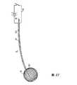
本発明のより更なる実施態様において、膨らませることができる弾力性のある風船が、組織に熱及び圧力を与えるために使用され得る。風船の外表面は、可とう性の、任意的に引き伸ばし可能な、電流が与えられたとき加熱するであろうところの電気的抵抗物質により部分的に又は全体的に被覆されるであろう。ここで、組織に働かされる圧力は、風船の膨張圧力の調節により制御され得る。In yet a further embodiment of the invention, a resilient balloon that can be inflated can be used to provide heat and pressure to the tissue. The outer surface of the balloon will be partially or wholly covered by a flexible, optionally stretchable, electrically resistive material that will heat up when given an electric current. Here, the pressure exerted on the tissue can be controlled by adjusting the inflation pressure of the balloon.
本発明の他の実施態様は、結腸内視術のために使用されるような内視鏡的「熱生検」鉗子における改善である。標準の「熱生検」鉗子は、慣用の電気外科的電源を使用し、そして不幸なことに、鉗子のジョーの外側であるところの腸壁の組織の過剰な焼灼の故に腸壁の貫通に関する懸念を伴う。「熱生検」鉗子の我々の実施態様は、鉗子のジョーの噛み付き部分(「歯」)の内側の部分にのみ電気的抵抗要素を組込むであろう。鉗子のジョーの残りの部分は、隣接する組織に断熱を提供するであろう材質により作られるであろう。このように、生検試料が良好な止血を伴って得られることができ、そして鉗子の外側において隣接する組織を不注意に焼灼すること(これは、穿孔をもたらし得る)から保護される。Another embodiment of the invention is an improvement in endoscopic “thermal biopsy” forceps, such as those used for colonoscopy. Standard “thermobiopsy” forceps use a conventional electrosurgical power source and unfortunately relate to penetration of the intestinal wall due to excessive cauterization of the intestinal wall tissue outside the forceps jaws. With concern. Our embodiment of a “thermal biopsy” forceps will incorporate an electrical resistance element only in the inner part of the jaw jaw biting portion (“tooth”) of the forceps. The rest of the forceps jaws will be made of a material that will provide thermal insulation to adjacent tissue. In this way, a biopsy sample can be obtained with good hemostasis and is protected from inadvertent cauterization of adjacent tissue outside the forceps, which can result in perforations.
本発明の更なる他の実施態様は、結腸内視術の間に使用されるところのポリープ切除係蹄(snare)に対する物理的外観及び機械的機能において類似する係蹄型デバイスであろう。単一極の電気外科的電源を使用するところの慣用の係蹄とは異なって、この実施態様の係蹄は、組織を係蹄で除去するところの実際の輪を作るために使用されるワイヤ又はバンドの部分のためにワイヤ又はバンドの内側の部分に使用された電気的抵抗物質を有するであろうところの特別に構成されたワイヤ又はバンドを使用するであろう。この実施態様は、電流が柄(stalk)を下って又はポリープの基部を通って広がることができ、及び下にある腸壁に損傷そして貫通さえ引起すかもしれないところの慣用の電気外科的係蹄とは反対に、係蹄内に捕らえられている組織物質中に熱エネルギーを向ける傾向がある。Yet another embodiment of the present invention would be a snare-type device that is similar in physical appearance and mechanical function to a polypectomy snare as used during colonoscopy. Unlike conventional snares that use a single-pole electrosurgical power source, this embodiment of snares is a wire used to create the actual annulus where tissue is removed with a snare. Or a specially constructed wire or band would be used that would have the electrical resistance material used for the wire or the inner part of the band for the part of the band. This embodiment allows conventional electrosurgical engagement where the current can spread down the stalk or through the base of the polyp and may cause damage and even penetration into the underlying intestinal wall. Contrary to hoofs, there is a tendency to direct thermal energy into tissue material that is trapped within the snare.
該デバイスは、外科手術に使用されることができ、かつ腹腔鏡的及び内視鏡的外科手術にとりわけ良く適している。我々の方法が、組織タンパク質の変性及び互いの粘着を得ることに一致する、最小量の熱エネルギーを最低温度で使用する故に、この方法に基づいて働くデバイスは、慣用の外科的エネルギーデバイスより効率的に機能できるであろう。それゆえ、これらのデバイスは、ポータブルかつバッテリー電力供給でさえあり得、これは、それらをポータブル又は軍隊での適用のために理想的に適合させる。The device can be used in surgery and is particularly well suited for laparoscopic and endoscopic surgery. Devices that work on this method are more efficient than conventional surgical energy devices because our method uses a minimum amount of thermal energy at the lowest temperature, consistent with obtaining tissue protein denaturation and adhesion to each other. Could be functional. Therefore, these devices can even be portable and battery powered, which makes them ideally suited for portable or military applications.
同時の熱エネルギー及び圧力の組合せ、タンパク質変性を作り出すために十分ではあるが過剰ではないところの温度及び圧力、及び処理領域を超えて周囲の組織への熱エネルギーの損失を最小にしながら処理される組織を互いに貼り付けることを促進するところの物理的配置及び構造材料により、外科手術的凝固、シール、結合又は切断を得ることを特に得ようとするところのデバイス又は方法は先行技術にはない。Processed with a combination of simultaneous thermal energy and pressure, temperature and pressure that is sufficient but not excessive to create protein denaturation, and minimal loss of thermal energy to the surrounding tissue beyond the processing region There is no device or method in the prior art that specifically seeks to obtain surgical coagulation, sealing, bonding or cutting due to the physical arrangement and structural material that facilitates affixing the tissues together.
付随する図面と関連させて以下の記載が参照され、ここで:
図1は本発明の一実施態様の略図である;
図1Aはジョーが閉じられた位置での図1の実施態様の線I−Iに沿った断面である;
図2は、図1の実施態様における下側ジョーの部分断面正面図であり、加熱および切断要素を示す;
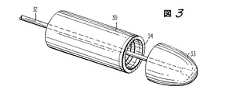
図3は本発明の他の実施態様の平面図である;
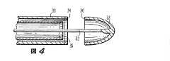
図4および5は図3の実施態様の断面図である;
図6および6Aは本発明のさらに別の実施態様のそれぞれ平面図および部分拡大図である;
図7および7Aは本発明の他の実施態様のそれぞれ平面図および部分断面図である;
図8は本発明のさらに別の実施態様の部分断面図である;
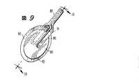
図9はさらに別の実施態様の平面図である;
図10は図9の実施態様の部分断面正面図である;および、
図11は組織を加熱および焼灼するための本発明の他の実施態様の平面図である。Reference is made to the following description in connection with the accompanying drawings, wherein:
FIG. 1 is a schematic diagram of one embodiment of the present invention;
FIG. 1A is a cross-section along line II of the embodiment of FIG. 1 with the jaws closed;
2 is a partial cross-sectional front view of the lower jaw in the embodiment of FIG. 1, showing the heating and cutting elements;
FIG. 3 is a plan view of another embodiment of the present invention;
4 and 5 are cross-sectional views of the embodiment of FIG. 3;
6 and 6A are a plan view and a partially enlarged view, respectively, of yet another embodiment of the present invention;
7 and 7A are a plan view and a partial cross-sectional view, respectively, of another embodiment of the present invention;
FIG. 8 is a partial cross-sectional view of yet another embodiment of the present invention;
FIG. 9 is a plan view of yet another embodiment;
10 is a partial cross-sectional front view of the embodiment of FIG. 9; and
FIG. 11 is a plan view of another embodiment of the present invention for heating and cauterizing tissue.
本発明は、おそらく図面からよりよく理解される。
図1は本発明の略図であり、該図は上側ジョー(jaw)10、下側ジョー12、該ジョーを開け及び閉じるためのレバー20を有するハンドル18に取り付けられた細長くされたシャフト14を示す。上側ジョー10はバネ支持部材13に蝶番11で取り付けられて、そしてバネ15は上側ジョー10およびバネ支持部材13の双方に取り付けられて、上側ジョー10をずらす。レバー20はロッド21を介して上側ジョー10または上側ジョー10および下側ジョー12の双方に操作可能に接続されている。シャフト14のハンドル18に最も近い端部には、(1)プッシャー16が備えられ、それは部材17及びコネクター23を介して下側ジョー12内に格納された(housed)切断ナイフブレード19に接続されており、および(2)トリガー22が備えられ、プッシャー16を駆動し、それは切断ナイフブレード19を駆動する。ハンドル18の下側端部18には充電可能なバッテリーパック24が備えられ、それは加熱要素アクチュエーター27および下側ジョー12内の加熱ワイヤ要素26に操作可能に接続されている。The present invention is probably better understood from the drawings.
FIG. 1 is a schematic representation of the present invention showing an elongated shaft 14 attached to a handle 18 having an
図1Aにおいて、組織部分25がジョー10と12の間に挟まれ、ブレード19によって切断される。In FIG. 1A,
図2は下側ジョーの平面図であり、ジョー12内の加熱ワイヤ要素26および切断ブレード19のためのスロット28の相対的位置を示す。加熱ワイヤ要素26は、該ワイヤが実質的にジョー12の表面と同じ高さであるような深さの溝内部に在る。好ましくは、組織の平行な2つの部分のみがシールされるように、加熱ワイヤ要素26の遠位部分29は、加熱ワイヤ要素26の面の下部または面からはずれて(out of)いる。加熱ワイヤ要素26(それは、好ましくはニクロムまたはいかなる他の適した電気抵抗性金属または合金、または電気抵抗性薄膜またはコーティングからなる)は、好ましくは適した熱伝導性の、電気抵抗性の、付着性でない(non-stick)コーティングを有する。例は、ポリテトラフロロエチレン(PTFE)、例えばTEFLON(商標)または調理用具に用いられている他の付着性でないコーティングを含む。さらに、上側ジョー10および下側ジョー12の向かい合った表面の一または両方は、任意的に、波形が付けられ、不規則であり、または溝が付けられていてよい。 FIG. 2 is a plan view of the lower jaw showing the relative position of the slot 28 for the
上側および下側ジョーの両方は、例えばセラミックのような物質からなり、それは熱的に絶縁され又は熱的に反射性である。このようにして、加熱要素によって生成される熱はジョーとジョーの間の空間に閉じ込められ、そして、ジョーの外側と接触し得る他の組織へと広がること、または輻射することができない。これは2つの意味で利点である:第1に、加熱要素により生成された熱は効率的に使用されて所望されたシーリングまたは凝固を行ない、および、第2に周囲の組織を不注意な熱的損傷から守る。Both the upper and lower jaws are made of a material such as ceramic, which is thermally insulated or thermally reflective. In this way, the heat generated by the heating element is trapped in the space between the jaws and cannot spread or radiate to other tissues that can contact the outside of the jaws. This is an advantage in two ways: First, the heat generated by the heating element is used efficiently to provide the desired sealing or coagulation, and secondly, careless heat to the surrounding tissue. Protect from mechanical damage.
当業者によって認められるように、本発明に従い、加熱、圧力、及び/又は切断機能は、機械的、電子機械的、または電子的に同調されて最適な結果を得ることが可能である。さらに、図1、1A及び2に示されたデバイスは、任意にカッター要素を有していなくてよい。そのようなデバイスは、組織をつなぐために、またはさもなくば組織を加熱および焼灼して凝固を生成するために、加熱および圧力のみが必要である状態を企図される。As will be appreciated by those skilled in the art, in accordance with the present invention, the heating, pressure, and / or cutting functions can be mechanically, electromechanically, or electronically tuned for optimal results. Furthermore, the devices shown in FIGS. 1, 1A and 2 may optionally have no cutter elements. Such devices are contemplated in situations where only heating and pressure are required to join the tissue or otherwise heat and cauterize the tissue to produce a coagulation.
図3及び4に示される実施態様において、円筒状部材30は同心的にロッド32の周囲に位置され、その遠位部分はアンビル33(anvil)を形成する。円筒状部材30の遠位表面は、加熱要素34内部において同心的に配置された環状加熱要素34および環状切断要素35を含む。アンビル33はロッド32が近位に動かされたときに、アンビル33の近位の環状エッジ36が加熱要素34と協動して組織を凝固またはシールするように構成されている。In the embodiment shown in FIGS. 3 and 4, the
図3および4の実施態様の使用は、図5によって理解され、そこにおいて、例えば、腸の2つの部分38,39が互いに結合されるべく置かれている。最初に、各部分38,39の一端がロッド32の周囲の結紮糸(ligatures)40、41と緩く結合される。次いで、ロッド32が遠位に動かされてアンビル33の環状エッジ36が腸の部分38,39を加熱要素34と接触させる。腸の部分38,39が互いに結合され、そして余分の組織が切断要素35によって切り取られる。ロッド32は次いでさらに近位方向に引かれて余分の組織、円筒状部位30およびアンビル33を除去する。The use of the embodiment of FIGS. 3 and 4 is understood by FIG. 5 in which, for example, the two
加えて、熱および圧力によって環状の吻合を作るための図3〜5に示されるデバイスは、ステープル等の機械的固定要素をさらに含むことができる。そのようなデバイスが図6および6Aに示され、そこにおいて、環状ステープリングデバイス42は、メインシャフト43、ハンドル44、ステープルハウジング45、およびアンビル46を含む。アンビル46は固定的にアンビルシャフト47の遠位端に取り付けられており、それはステープルハウジング45、メインシャフト43、およびハンドル44内部において、可動的に摺動可能である。In addition, the device shown in FIGS. 3-5 for creating an annular anastomosis by heat and pressure can further include mechanical fixation elements such as staples. Such a device is shown in FIGS. 6 and 6A, where an annular stapling device 42 includes a
ステープルハウジング45の遠位表面48はステープル(図示せず)および電気的に抵抗性のコーティングまたは部材50のためのスロット49を有する。カッティングエッジ52を有する内側の環状部材51は、図6Aにおいてより明瞭に見ることができるようにアンビルシャフト47の回りに円周状に配置される。任意に、スロット49およびコーティング50は同一の拡がりを有することができる。The
ハンドル44はアンビル46および加熱要素49を操作する手段およびステープルを打ち出す手段を含む。当業者によって理解されるように、ステープル打込みレバーまたは部材53はステープリングハウジング45内で円筒状押し 出し部材に操作的に結合されており、スロット49からステープルを放出する。
環状ステープリングデバイスの操作は、図3に示されるデバイスの操作と、結合されるべき組織中にステープルが打ち込まれることを除き類似している。好ましくは、ステープルはシーリングに次いで、且つ切断と同時に打ち込まれる。ステープルは熱エネルギーと共に作用して、組織のシール、ジョイントまたはボンドを強くし、一方熱エネルギーは該ステープルの止血能を強める。ステープルまたは環状以外の形態、例えば直線状、または角度付けられた形状の他の機械的組織ファスナーを熱エネルギーシーリングと共に用いることができる。The operation of the annular stapling device is similar to the operation of the device shown in FIG. 3, except that staples are driven into the tissue to be joined. Preferably, the staple is driven after sealing and simultaneously with cutting. Staples work with thermal energy to strengthen tissue seals, joints or bonds, while thermal energy enhances the hemostatic ability of the staples. Other mechanical tissue fasteners other than staples or rings, such as linear or angled shapes, can be used with thermal energy sealing.
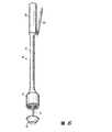
図7は基本的に組織コア除去デバイスであるところの本発明の実施態様を示す。組織コア除去デバイス56は固定的に取り付けられた近位に延びるハンドル60を有する円筒状部材58を含む。円筒状部材58は円筒状部材58の外側表面66の上に配置された鋭利な切断エッジ62および加熱要素64を含む。FIG. 7 shows an embodiment of the present invention that is essentially a tissue core removal device. Tissue
上記載と調和して、組織サンプルは、デバイス56を前方に動かすにつれ回転しながら、除去デバイス56を組織内に挿入することによって得られる。該回転は時計回りまたは反時計回りのいずれかであることができるが、エッジ62が切断するために十分な圧力と伴に、好ましくは交互に時計回り及び反時計回りである。加熱要素64は除去されるべき組織サンプルに隣接した組織を焼灼またはシールし、十分な深さの組織サンプルがシリンダー58内部に置かれた時、デバイス56が取り除かれる。従来行われているように、除去デバイス56は組織サンプルを除去する手段、例えば除去デバイス56の遠位端から該サンプルを放出するための、近位に延びるアクチュエーター60を有する内部ピストン59を好ましくは含む。当業者に理解されるように、組織コア除去デバイスは、追加の切断手段を、コア組織サンプルを組織マスから分離するのを援助するために、その遠位端に任意に有していてよい。Consistent with the above description, a tissue sample is obtained by inserting the
図8において、電気熱的バイオプシーニードルの遠位部分70は、組織サンプル78を捕獲するためのスロット76を有する内部のスロットを切られた筆状突起74の周囲に、外周的に、摺動可能に配置された外側の切断シース72を含む。該外側シース72は切断エッジ73を有し、それは、該外側シース72がアクチュエーター(図示せず)により遠位に推進されるとき、組織サンプル78を残余の組織マス(図示せず)から分離し、及び、サンプル78をスロット76内に閉じ込める。In FIG. 8, the
外側シース72は、その遠位部分に、電気的に抵抗性の膜75コーティングを好ましくは有する。膜75は、空間で隔たれた電気接点またはコネクター77を有していてよい。筆状突起74が内側切断部材(図示せず)を有するところの、バイオプシーニードルの他の実施態様において、該筆状突起または該内側切断部材、またはその双方は、電気抵抗性のコーティングまたは膜を有していてよい。
本発明の上記態様は公知のバイオプシーデバイスに組み込むことができる。例えば、米国特許第4,600,014号および第5,595,185号を見よ。これら双方ともに、バイオプシーに関するそれらの記載を参照することにより本明細書に含まれる。The above aspects of the invention can be incorporated into known biopsy devices. See, for example, US Pat. Nos. 4,600,014 and 5,595,185. Both of these are included herein by reference to their description regarding biopsy.
図9および10は本発明の環状切断の態様を示し、そこでは、鋭利な外側エッジ82を有するディスク80がその中心において、ハンドル88のフォーク86に回転可能に固定されているロッド84に取り付けられている。エッジ82に隣接するのは、環状加熱要素90であり、それはディスク80の一または両面上に在ることができる。各々の加熱要素90は、フォーク86に電気的に、例えば1または2以上のブラッシ91を介して、接続されている。FIGS. 9 and 10 show an embodiment of the annular cutting of the present invention, in which a
図11は、加熱および焼灼デバイス92がカテーテル94およびカテーテル94の遠位端に封止的に(sealingly)取り付けられた膨張可能なバルーン96を含むところの本発明の実施態様を表す。カテーテル94は、少なくとも1つの内腔98を有し、それは膨張または収縮させるためにバルーン96と流体連結している。カテーテル94の近位端は、バルーン96を膨張または収縮させるために、調整された圧力源または膨張源(図示せず)と流体連結している。FIG. 11 represents an embodiment of the invention in which the heating and ablation device 92 includes a
バルーン96は電気的抵抗性の膜コーティング100を有し、その少なくとも2つの離れた部分は、カテーテル94に沿って近位にまたはカテーテル94の中を電源104まで延びるワイヤ102に接続されている。電気的に抵抗性の膜コーティング100は、バルーン96外表面の全部では無いにせよ、かなりの部分を蓋うように意図される。Balloon 96 has an electrically
使用に際し、収縮されたバルーン96を有するデバイス92は患者の体内で、例えば体内的にまたは経皮的に操作されて、焼灼すべき部位に隣接してバルーン96が配置される。次いで、焼灼すべき場所に電気的に抵抗性の膜コーティング100が接触するようにバルーン96が膨張させられると、膜コーティング100は源104からの電気的エネルギーを与えられる。熱および圧力が所望された効果を産んだ後、電力が切られ、そして取り出しを容易にするために、バルーンが収縮される。In use, the device 92 having the deflated balloon 96 is manipulated in the patient's body, eg, in vivo or percutaneously, to place the balloon 96 adjacent to the site to be cauterized. The
図3〜10に示す本発明の実施態様に関して、各々の加熱要素は適切な電力供給源へと電気的に接続されることが理解されるべきである。各々の場合において、電力供給源はバッテリーまたはバッテリーパックであることができ、それは各々のデバイスに固定的に取り付けられまたは一体化されることが想起される。任意に、バッテリーまたはバッテリーパックは、例えば作業者が身に付けるためのクリップまたはベルト手段のように、分離して据え付けられまたは配置されることができる。他の標準的な電力源、例えばトランス、も使用してよいことは本発明の範囲内である。他の熱源、例えばブタンのような燃料、または化学反応、を使用してもよい。With respect to the embodiment of the invention shown in FIGS. 3-10, it should be understood that each heating element is electrically connected to a suitable power supply. In each case, it is recalled that the power supply can be a battery or a battery pack, which is fixedly attached to or integrated with each device. Optionally, the battery or battery pack can be separately installed or placed, such as a clip or belt means for an operator to wear. It is within the scope of the present invention that other standard power sources such as transformers may also be used. Other heat sources may be used, for example fuels such as butane, or chemical reactions.
上述したように、本発明の一の側面は、最大の組織シール強度および最小の付随する組織損傷を達成するために、(1)熱エネルギーの適用、すなわち、温度及び時間、および(2)圧力、すなわち、力及び継続時間の最適化に関する。当業者は、有用なパラメータは大きく異なることを認めるであろう。As mentioned above, one aspect of the present invention is to achieve (1) application of thermal energy, i.e. temperature and time, and (2) pressure, in order to achieve maximum tissue seal strength and minimum accompanying tissue damage. That is, it relates to optimization of force and duration. Those skilled in the art will appreciate that useful parameters vary widely.
しかし、人間組織への実際的な適用において、約0.5〜約14ボルト、好ましくは約1〜約12ボルトの電圧、が蛋白質を変性させるのに適した温度へと組織を加熱する熱エネルギーを生成するのに十分な抵抗を有する加熱要素に適用される。この温度は約45〜約100℃の範囲である。適用される圧力は、癒合を与えるに十分であるが、組織そのものをつぶすまたは破壊するよりも小さい。However, in practical applications in human tissue, a voltage of about 0.5 to about 14 volts, preferably about 1 to about 12 volts, generates thermal energy that heats the tissue to a temperature suitable for denaturing proteins. Applied to a heating element with sufficient resistance to This temperature ranges from about 45 to about 100 ° C. The applied pressure is sufficient to provide healing, but less than crushing or destroying the tissue itself.
組織の凝固、シール、吻合、または溶接の強さは実験的に測定される。例えば、裂けた血管の側面に作られた凝固の強さは、最初に凝固を作り、そして、測定された大きさの静止圧を血管の内側に、凝固が破裂しそして出血が再開するまで与えることにより実験的に測定することができる。組織溶接の強さは、最初に2つの組織を結合し、そして該結合された組織を、増加し且つ測定された大きさの力で組織を引き離そうとする機械の中へと置くことにより測定することができる。付随する熱損傷も測定できる量であり、すなわち、付随する熱損傷の量は目視によりまたは顕微鏡で容易に評価できる。この方法を用いることにより、最適化されたパラメータの表を、いかなるタイプの組織についても、作ることができる。これらのパラメータは、凝固、シーリング、結合プロセスの間の、加熱要素の電圧、電流、および抵抗、および、組織を互いに押し付けるための圧力量、ならびに該プロセスの持続時間、も選択することにより種々のデバイスに取り込まれる。これらのパラメータは単にデバイス中に取り込まれることができる(すなわち、簡易な機械的タイマー、固定プリセット電圧および電流、およびバネが積載された圧力デバイス、または、我々はROM中の「探索表(look-uptable)」に導かれ、及び高度な機械的力/圧力センサーおよび歪みゲージを用いることによって、加熱プロセスのマイクロプロセッサー制御に基づく、より柔軟性で活動的な制御を組込むことができる)。さらに、ある用途については、熟練した作業者に、目視または他の感知手段により、エネルギーを与える時間および必要な圧力量を決定させるだけで十分で有り得る。The strength of tissue coagulation, sealing, anastomosis, or welding is measured experimentally. For example, the strength of coagulation created on the side of a torn blood vessel will initially create coagulation and give a measured amount of static pressure inside the blood vessel until the coagulation ruptures and bleeding resumes This can be measured experimentally. The strength of tissue welding is measured by first joining the two tissues and placing the joined tissues into a machine that attempts to separate the tissues with increasing and measured force. be able to. The amount of incidental thermal damage is also measurable, that is, the amount of incidental thermal damage can be easily assessed visually or with a microscope. By using this method, an optimized parameter table can be created for any type of tissue. These parameters can be varied by selecting the heating element voltage, current, and resistance during the coagulation, sealing, bonding process, and the amount of pressure to press the tissue together, as well as the duration of the process. Captured on the device. These parameters can simply be captured in the device (ie a simple mechanical timer, fixed preset voltage and current, and a spring loaded pressure device, or we look- By using advanced mechanical force / pressure sensors and strain gauges, it is possible to incorporate more flexible and active control based on microprocessor control of the heating process). Furthermore, for certain applications, it may be sufficient to have a skilled worker determine the time to apply energy and the amount of pressure required by visual or other sensing means.
本発明のデバイスは、何らかの適した物質により作られてよく、当業者にとって周知であるような、例えば、ガラスファイバー強化ポリカーボネートのような強化エンジニアリングプラスチックまたは機械加工できる乃至は射出成形されたセラミックス、または高温ガラスまたはエポキシ、または雲母から作られてよい。あるいは、適した合金鋼、例えば318ステンレス鋼等から作られてよい。加熱要素は簡易な抵抗性ワイヤまたは、電導性または半電導性の金属、有機金属、または有機物質からなる薄膜またはコーティングであってよい。作製のための実際の物質は、デバイスが繰り返しまたは使い捨てで使用されるかに依存して選択できる。実際、後者の場合、デバイスの種々の部分は金属合金及び/又はプラスチックで作られてよいと考えられ、その場合、プラスチックの使い捨て部品は、各使用後に捨てられ且つより高価な金属合金部分が再使用される。複雑なおよび高価な制御回路が使用される場合には、デバイスのこの部分は再使用可能なように作られることができる。The device of the present invention may be made of any suitable material and is well known to those skilled in the art, for example, reinforced engineering plastics such as glass fiber reinforced polycarbonate or machinable or injection molded ceramics, or It may be made from hot glass or epoxy, or mica. Alternatively, it may be made from a suitable alloy steel, such as 318 stainless steel. The heating element may be a simple resistive wire or a thin film or coating made of a conductive or semiconductive metal, organometallic, or organic material. The actual material for fabrication can be selected depending on whether the device is used repeatedly or disposable. In fact, in the latter case, it is believed that the various parts of the device may be made of metal alloys and / or plastics, in which case the plastic disposable parts are discarded after each use and the more expensive metal alloy parts are regenerated. used. If complex and expensive control circuits are used, this part of the device can be made reusable.
上の記載に含まれ、且つ添付する図面に示された総ての事項は、例示として、限定する趣旨ではないものとして解釈されるべきである。また、以下の請求の範囲は、本明細書に記載された発明の一般的及び特定の特徴、及び、文言上はその間から洩れると言われるかもしれない発明範囲の記述の総てを網羅するものと理解される。All matters contained in the above description and shown in the accompanying drawings should be interpreted as illustrative and not limiting. Further, the following claims cover all general and specific features of the invention described in the present specification, and all descriptions of the scope of the invention which may be said to be leaked in between. It is understood.
Claims (25)
Translated fromJapanese遠位端および近位端を有する細長い部材であって、その近位端がハンドルに取り付けられているところの部材、
それぞれ遠位端および近位端を有しかつそれぞれ作業表面を有する、二つの対向して位置されている上側および下側ジョー部材であって、上記細長い部材の遠位端に位置されかつ回転可能に互いに対し取り付けられているところのジョー部材、
ひとつのジョー部材の作業表面の内にまたは該表面に隣接して位置されている切断手段および
少なくともひとつのジョー部材の作業表面の内にまたは該表面の上に位置される加熱要素
を含むところのデバイス。In a device for sealing and cutting tissue,
An elongated member having a distal end and a proximal end, the proximal end of which is attached to the handle;
Two opposingly positioned upper and lower jaw members, each having a distal end and a proximal end, and each having a working surface, positioned and rotatable at the distal end of the elongate member Jaw members attached to each other,
Cutting means located within or adjacent to the working surface of one jaw member and a heating element located within or on the working surface of at least one jaw member device.
請求項1のデバイスの開いたジョー内に組織を位置付けること、
ジョーを閉じて組織を所定位置に保持すること、
加熱要素を発動して、組織の一部を変性させかつ互いにシールさせもしくは結合させること、そして、
切断手段を発動して、組織のシールされた領域間で組織を切断すること
の工程を含む方法。In the way to cut the tissue,
Positioning tissue within an open jaw of the device of claim 1;
Closing the jaws to hold the tissue in place,
Activating a heating element to denature portions of tissue and seal or bond together; and
Activating the cutting means to cut tissue between sealed areas of tissue.
互いに隣接する、組織の第一のおよび第二のセクションを保持するためのホルダー、
組織を加熱するための、ホルダー内の加熱要素、および
圧力を発生するための、ホルダーと結びついた圧力手段、
を含み
ここで、付随する組織への損傷を最小にしながら組織シールまたは結合の強度を最大にするべく最適の圧力下で最適の時間かつ最適の温度で組織のセクションが加熱されるところの方法。In a device for joining tissues,
Holders for holding the first and second sections of tissue, adjacent to each other
A heating element in the holder for heating the tissue, and a pressure means associated with the holder for generating pressure,
Wherein the section of tissue is heated at an optimal time and at an optimal temperature to maximize the strength of the tissue seal or bond while minimizing associated damage to the tissue.
互いに結合されるべきひとつの領域をそれぞれ有する組織の二つのセクションを位置付けて、該領域が互いに隣接するようにすること、そして
結合またはシールの強度が最大化されかつ付随する組織への在りうる損傷が最小化されるように組織の該領域を互いに結合させるべく、最適の熱エネルギーおよび最適の圧力を適用すること
を含む方法。In a method for joining tissues,
Position two sections of tissue each having one region to be bonded together so that the regions are adjacent to each other, and possible damage to the associated tissue where the strength of the bond or seal is maximized Applying optimal thermal energy and optimal pressure to bond the regions of tissue together so that is minimized.
近位端および遠位端を有するロッド部材であって、該遠位端は中空の実質的に半球状のセクションを有し、該中空のセクションは近位に向きかつ環状のエッジを有するところのロッド部材、
該ロッド部材を同心状に取り囲みかつ近位端および遠位端を有する第一の円柱状部材であって、該遠位端が内側の環状切断エッジを有するところの第一の円柱状部材、および
該第一の円柱状部材を同心状に取り囲みかつ近位端および遠位端を有する第二の円柱状部材であって、該遠位端が環状の加熱要素を有するところの第二の円柱状部材を有し、
ここで該ロッド部材は、該円柱状部材内で可動であり、半球状セクションの環状エッジは該加熱要素と協働する
ところのデバイス。In a device for joining tubular sections of tissue,
A rod member having a proximal end and a distal end, the distal end having a hollow substantially hemispherical section, the hollow section having a proximally facing and annular edge. Rod members,
A first cylindrical member concentrically surrounding the rod member and having a proximal end and a distal end, wherein the distal end has an inner annular cutting edge; and A second cylindrical member concentrically surrounding the first cylindrical member and having a proximal end and a distal end, the distal end having an annular heating element Having a member,
Wherein the rod member is movable within the cylindrical member and the annular edge of the hemispherical section cooperates with the heating element.
請求項12のデバイスのロッドの周りに、近位端および遠位端を有する第一の円筒状組織セクションの遠位端を位置付けること、
第一の円筒状組織セクションの遠位端に遠位の該ロッドの周りに、近位端および遠位端を有する第二の円筒状組織セクションの近位端を位置付けること、
実質的に半球状のセクションを近位方向に動かして、該実質的に半球状のセクションをして第一の円筒状組織セクションの遠位部分および第二の円筒状組織セクションの近位部分を加熱要素に対して押し付けること、
工程(c)からの組織セクションを加熱して、組織セクションを互いに結合すること、そして、
内側の環状エッジを遠位方向に動かして、不必要な組織を切断すること
の工程を含む方法。In a method for anastomosing tissue,
Positioning a distal end of a first cylindrical tissue section having a proximal end and a distal end about the rod of the device of claim 12;
Positioning a proximal end of a second cylindrical tissue section having a proximal end and a distal end about the rod distal to the distal end of the first cylindrical tissue section;
Moving the substantially hemispherical section proximally to move the substantially hemispherical section into a distal portion of the first cylindrical tissue section and a proximal portion of the second cylindrical tissue section. Pressing against the heating element,
Heating the tissue sections from step (c) to bond the tissue sections together; and
Moving the inner annular edge distally to cut unwanted tissue.
近位端および遠位端を有する円柱状部材であって、該遠位端が切断エッジを有するところの円柱状部材、および
該円柱状部材の近位端に固定的に結合されているハンドルを有し、
ここで円柱状部材は、電力源に電気的に接続されている加熱要素を含む外側表面を有するところの
組織コアサンプル採取器。In tissue core sampler,
A cylindrical member having a proximal end and a distal end, wherein the distal end has a cutting edge, and a handle fixedly coupled to the proximal end of the cylindrical member Have
Wherein the cylindrical member has an outer surface that includes a heating element electrically connected to a power source.
ひとつの鋭い外側エッジおよび二つの外側表面を有する環状ディスク、ここで該外側表面の一つまたは二つは該鋭い外側エッジの近傍に位置付けられている環状加熱要素を有している、
ディスクの中心に回転可能に結合されているハンドル、および
各加熱要素に電気的に結合されている電力源
を有する組織カッター。In the tissue cutter,
An annular disc having one sharp outer edge and two outer surfaces, wherein one or two of the outer surfaces have an annular heating element positioned in the vicinity of the sharp outer edge;
A tissue cutter having a handle rotatably coupled to the center of the disk and a power source electrically coupled to each heating element.
(a)遠位端および近位端を有する細長い部材であって、その近位端はハンドルに取り付けられている部材、
(b)それぞれ遠位端および近位端を有しかつそれぞれ作業表面を有する、二つの対向して位置されている上側および下側ジョー部材であって、該ジョー部材は上記細長い部材の遠位端に位置されかつそれらのそれぞれの近位端において回転可能に互いに対し取り付けられているところのジョー部材、および
(c)少なくともひとつのジョー部材の作業表面の内にまたは該表面の上に位置される加熱要素
を有するデバイス。In a device for sealing tissue,
(A) an elongate member having a distal end and a proximal end, the proximal end being attached to the handle;
(B) two opposingly positioned upper and lower jaw members each having a distal end and a proximal end and each having a working surface, the jaw members being distal to the elongate member; Jaw members located at the ends and rotatably attached to each other at their respective proximal ends, and (c) located within or on the working surface of the at least one jaw member A device with a heating element.
付随する組織損傷を最小にしながら組織シール強度を最大にするべく最適の圧力下で最適の時間かつ最適の温度で該組織セクションを加熱するための加熱要素および圧力手段をデバイスが含むことを特徴とするデバイス。A device for joining tissue sections, wherein the tissue sections are positioned in close proximity to each other and staples are driven together into the tissue sections to join them together.
The device includes a heating element and pressure means for heating the tissue section at an optimal time and at an optimal temperature under an optimal pressure to maximize tissue seal strength while minimizing associated tissue damage. Device to use.
付随する組織損傷を最小にしながら組織シール強度を最大にするべく最適の圧力下で最適の時間かつ最適の温度で該組織セクションを加熱するための加熱要素および圧力手段をデバイスが含むことを特徴とするデバイス。A device for joining tissue sections, wherein the tissue sections are positioned in close proximity to each other, staples are driven into the tissue sections to join them together, and unwanted tissue is removed Devices,
The device includes a heating element and pressure means for heating the tissue section at an optimal time and at an optimal temperature under an optimal pressure to maximize tissue seal strength while minimizing associated tissue damage. Device to use.
Applications Claiming Priority (2)
| Application Number | Priority Date | Filing Date | Title |
|---|---|---|---|
| US3858997P | 1997-03-05 | 1997-03-05 | |
| US60/038,589 | 1997-03-05 |
Related Parent Applications (1)
| Application Number | Title | Priority Date | Filing Date |
|---|---|---|---|
| JP53881898ADivisionJP2001514541A (en) | 1997-03-05 | 1998-03-05 | Electrothermal device for sealing and bonding or cutting tissue |
Publications (2)
| Publication Number | Publication Date |
|---|---|
| JP2008043789Atrue JP2008043789A (en) | 2008-02-28 |
| JP4887257B2 JP4887257B2 (en) | 2012-02-29 |
Family
ID=21900773
Family Applications (2)
| Application Number | Title | Priority Date | Filing Date |
|---|---|---|---|
| JP53881898APendingJP2001514541A (en) | 1997-03-05 | 1998-03-05 | Electrothermal device for sealing and bonding or cutting tissue |
| JP2007264731AExpired - LifetimeJP4887257B2 (en) | 1997-03-05 | 2007-10-10 | Electrothermal device for sealing and / or cutting tissue |
Family Applications Before (1)
| Application Number | Title | Priority Date | Filing Date |
|---|---|---|---|
| JP53881898APendingJP2001514541A (en) | 1997-03-05 | 1998-03-05 | Electrothermal device for sealing and bonding or cutting tissue |
Country Status (10)
| Country | Link |
|---|---|
| EP (1) | EP1011494B1 (en) |
| JP (2) | JP2001514541A (en) |
| AT (1) | ATE349954T1 (en) |
| AU (1) | AU6448798A (en) |
| BR (1) | BR9808202A (en) |
| CA (2) | CA2283392C (en) |
| DE (1) | DE69836817T2 (en) |
| ES (1) | ES2279570T3 (en) |
| PT (1) | PT1011494E (en) |
| WO (1) | WO1998038935A1 (en) |
Cited By (9)
| Publication number | Priority date | Publication date | Assignee | Title |
|---|---|---|---|---|
| JP2011504794A (en)* | 2007-11-28 | 2011-02-17 | シンセオン,エルエルシー | Cordless power-assisted medical cautery and cutting device |
| US8551088B2 (en) | 2008-03-31 | 2013-10-08 | Applied Medical Resources Corporation | Electrosurgical system |
| US9320563B2 (en) | 2010-10-01 | 2016-04-26 | Applied Medical Resources Corporation | Electrosurgical instruments and connections thereto |
| JP2017515635A (en)* | 2014-04-29 | 2017-06-15 | ウィリアム ディーン ウォレスWALLACE, William, Dean | Treatment method and portable surgical device for treating cervical neoplastic and proliferative cells and other dermatological or surface related diseases |
| US10149713B2 (en) | 2014-05-16 | 2018-12-11 | Applied Medical Resources Corporation | Electrosurgical system |
| US10420603B2 (en) | 2014-12-23 | 2019-09-24 | Applied Medical Resources Corporation | Bipolar electrosurgical sealer and divider |
| US10792092B2 (en) | 2014-05-30 | 2020-10-06 | Applied Medical Resources Corporation | Electrosurgical seal and dissection systems |
| US11696796B2 (en) | 2018-11-16 | 2023-07-11 | Applied Medical Resources Corporation | Electrosurgical system |
| US11864812B2 (en) | 2018-09-05 | 2024-01-09 | Applied Medical Resources Corporation | Electrosurgical generator control system |
Families Citing this family (575)
| Publication number | Priority date | Publication date | Assignee | Title |
|---|---|---|---|---|
| US6626901B1 (en)* | 1997-03-05 | 2003-09-30 | The Trustees Of Columbia University In The City Of New York | Electrothermal instrument for sealing and joining or cutting tissue |
| CA2283392C (en)* | 1997-03-05 | 2009-06-30 | The Trustees Of Columbia University In The City Of New York | Electrothermal device for sealing and joining or cutting tissue |
| US6562037B2 (en) | 1998-02-12 | 2003-05-13 | Boris E. Paton | Bonding of soft biological tissues by passing high frequency electric current therethrough |
| EP0979635A2 (en) | 1998-08-12 | 2000-02-16 | Origin Medsystems, Inc. | Tissue dissector apparatus |
| US7534243B1 (en) | 1998-08-12 | 2009-05-19 | Maquet Cardiovascular Llc | Dissection and welding of tissue |
| US7485092B1 (en) | 1998-08-12 | 2009-02-03 | Maquet Cardiovascular Llc | Vessel harvesting apparatus and method |
| US20030171747A1 (en)* | 1999-01-25 | 2003-09-11 | Olympus Optical Co., Ltd. | Medical treatment instrument |
| US6558313B1 (en) | 2000-11-17 | 2003-05-06 | Embro Corporation | Vein harvesting system and method |
| DE60142587D1 (en)* | 2001-04-06 | 2010-08-26 | Covidien Ag | Blood vessel sealing and separating device |
| AT411216B (en)* | 2002-01-25 | 2003-11-25 | Schubert Heinrich Dr | DEVICE FOR PRODUCING ANASTOMOSIS BETWEEN HOLLOW ORGANS |
| US6733498B2 (en) | 2002-02-19 | 2004-05-11 | Live Tissue Connect, Inc. | System and method for control of tissue welding |
| US7326202B2 (en)* | 2003-03-07 | 2008-02-05 | Starion Instruments Corporation | Tubular resistance heater with electrically insulating high thermal conductivity core for use in a tissue welding device |
| US20070084897A1 (en) | 2003-05-20 | 2007-04-19 | Shelton Frederick E Iv | Articulating surgical stapling instrument incorporating a two-piece e-beam firing mechanism |
| US9060770B2 (en) | 2003-05-20 | 2015-06-23 | Ethicon Endo-Surgery, Inc. | Robotically-driven surgical instrument with E-beam driver |
| US11998198B2 (en) | 2004-07-28 | 2024-06-04 | Cilag Gmbh International | Surgical stapling instrument incorporating a two-piece E-beam firing mechanism |
| US8215531B2 (en) | 2004-07-28 | 2012-07-10 | Ethicon Endo-Surgery, Inc. | Surgical stapling instrument having a medical substance dispenser |
| US11890012B2 (en) | 2004-07-28 | 2024-02-06 | Cilag Gmbh International | Staple cartridge comprising cartridge body and attached support |
| US9072535B2 (en) | 2011-05-27 | 2015-07-07 | Ethicon Endo-Surgery, Inc. | Surgical stapling instruments with rotatable staple deployment arrangements |
| US7528175B2 (en) | 2004-10-08 | 2009-05-05 | Inverseon, Inc. | Method of treating airway diseases with beta-adrenergic inverse agonists |
| US8814861B2 (en) | 2005-05-12 | 2014-08-26 | Innovatech, Llc | Electrosurgical electrode and method of manufacturing same |
| US20070055326A1 (en) | 2005-07-21 | 2007-03-08 | Farley Brian E | Method of treating a hollow anatomical structure with a thermal catheter |
| EP2662042A3 (en)* | 2005-07-21 | 2017-03-22 | Covidien LP | Systems and methods for treating a hollow anatomical structure |
| US7673781B2 (en) | 2005-08-31 | 2010-03-09 | Ethicon Endo-Surgery, Inc. | Surgical stapling device with staple driver that supports multiple wire diameter staples |
| US11484312B2 (en) | 2005-08-31 | 2022-11-01 | Cilag Gmbh International | Staple cartridge comprising a staple driver arrangement |
| US7669746B2 (en) | 2005-08-31 | 2010-03-02 | Ethicon Endo-Surgery, Inc. | Staple cartridges for forming staples having differing formed staple heights |
| US10159482B2 (en) | 2005-08-31 | 2018-12-25 | Ethicon Llc | Fastener cartridge assembly comprising a fixed anvil and different staple heights |
| US11246590B2 (en) | 2005-08-31 | 2022-02-15 | Cilag Gmbh International | Staple cartridge including staple drivers having different unfired heights |
| US9237891B2 (en) | 2005-08-31 | 2016-01-19 | Ethicon Endo-Surgery, Inc. | Robotically-controlled surgical stapling devices that produce formed staples having different lengths |
| US8800838B2 (en) | 2005-08-31 | 2014-08-12 | Ethicon Endo-Surgery, Inc. | Robotically-controlled cable-based surgical end effectors |
| US7934630B2 (en) | 2005-08-31 | 2011-05-03 | Ethicon Endo-Surgery, Inc. | Staple cartridges for forming staples having differing formed staple heights |
| US20070106317A1 (en) | 2005-11-09 | 2007-05-10 | Shelton Frederick E Iv | Hydraulically and electrically actuated articulation joints for surgical instruments |
| US8820603B2 (en) | 2006-01-31 | 2014-09-02 | Ethicon Endo-Surgery, Inc. | Accessing data stored in a memory of a surgical instrument |
| US8161977B2 (en) | 2006-01-31 | 2012-04-24 | Ethicon Endo-Surgery, Inc. | Accessing data stored in a memory of a surgical instrument |
| US8708213B2 (en) | 2006-01-31 | 2014-04-29 | Ethicon Endo-Surgery, Inc. | Surgical instrument having a feedback system |
| US20110295295A1 (en) | 2006-01-31 | 2011-12-01 | Ethicon Endo-Surgery, Inc. | Robotically-controlled surgical instrument having recording capabilities |
| US20120292367A1 (en) | 2006-01-31 | 2012-11-22 | Ethicon Endo-Surgery, Inc. | Robotically-controlled end effector |
| US7845537B2 (en) | 2006-01-31 | 2010-12-07 | Ethicon Endo-Surgery, Inc. | Surgical instrument having recording capabilities |
| US11278279B2 (en) | 2006-01-31 | 2022-03-22 | Cilag Gmbh International | Surgical instrument assembly |
| US20110024477A1 (en) | 2009-02-06 | 2011-02-03 | Hall Steven G | Driven Surgical Stapler Improvements |
| US11224427B2 (en) | 2006-01-31 | 2022-01-18 | Cilag Gmbh International | Surgical stapling system including a console and retraction assembly |
| US11793518B2 (en) | 2006-01-31 | 2023-10-24 | Cilag Gmbh International | Powered surgical instruments with firing system lockout arrangements |
| US9861359B2 (en) | 2006-01-31 | 2018-01-09 | Ethicon Llc | Powered surgical instruments with firing system lockout arrangements |
| US7753904B2 (en) | 2006-01-31 | 2010-07-13 | Ethicon Endo-Surgery, Inc. | Endoscopic surgical instrument with a handle that can articulate with respect to the shaft |
| US8186555B2 (en) | 2006-01-31 | 2012-05-29 | Ethicon Endo-Surgery, Inc. | Motor-driven surgical cutting and fastening instrument with mechanical closure system |
| US8236010B2 (en) | 2006-03-23 | 2012-08-07 | Ethicon Endo-Surgery, Inc. | Surgical fastener and cutter with mimicking end effector |
| US8992422B2 (en) | 2006-03-23 | 2015-03-31 | Ethicon Endo-Surgery, Inc. | Robotically-controlled endoscopic accessory channel |
| US9770230B2 (en) | 2006-06-01 | 2017-09-26 | Maquet Cardiovascular Llc | Endoscopic vessel harvesting system components |
| US8322455B2 (en) | 2006-06-27 | 2012-12-04 | Ethicon Endo-Surgery, Inc. | Manually driven surgical cutting and fastening instrument |
| US7506791B2 (en)* | 2006-09-29 | 2009-03-24 | Ethicon Endo-Surgery, Inc. | Surgical stapling instrument with mechanical mechanism for limiting maximum tissue compression |
| US20110087276A1 (en) | 2009-10-09 | 2011-04-14 | Ethicon Endo-Surgery, Inc. | Method for forming a staple |
| US10568652B2 (en) | 2006-09-29 | 2020-02-25 | Ethicon Llc | Surgical staples having attached drivers of different heights and stapling instruments for deploying the same |
| US10130359B2 (en) | 2006-09-29 | 2018-11-20 | Ethicon Llc | Method for forming a staple |
| US11980366B2 (en) | 2006-10-03 | 2024-05-14 | Cilag Gmbh International | Surgical instrument |
| US8652120B2 (en) | 2007-01-10 | 2014-02-18 | Ethicon Endo-Surgery, Inc. | Surgical instrument with wireless communication between control unit and sensor transponders |
| US8684253B2 (en) | 2007-01-10 | 2014-04-01 | Ethicon Endo-Surgery, Inc. | Surgical instrument with wireless communication between a control unit of a robotic system and remote sensor |
| US8632535B2 (en) | 2007-01-10 | 2014-01-21 | Ethicon Endo-Surgery, Inc. | Interlock and surgical instrument including same |
| US11291441B2 (en) | 2007-01-10 | 2022-04-05 | Cilag Gmbh International | Surgical instrument with wireless communication between control unit and remote sensor |
| US8459520B2 (en) | 2007-01-10 | 2013-06-11 | Ethicon Endo-Surgery, Inc. | Surgical instrument with wireless communication between control unit and remote sensor |
| US11039836B2 (en) | 2007-01-11 | 2021-06-22 | Cilag Gmbh International | Staple cartridge for use with a surgical stapling instrument |
| US20080169333A1 (en) | 2007-01-11 | 2008-07-17 | Shelton Frederick E | Surgical stapler end effector with tapered distal end |
| US7673782B2 (en) | 2007-03-15 | 2010-03-09 | Ethicon Endo-Surgery, Inc. | Surgical stapling instrument having a releasable buttress material |
| US8893946B2 (en) | 2007-03-28 | 2014-11-25 | Ethicon Endo-Surgery, Inc. | Laparoscopic tissue thickness and clamp load measuring devices |
| US8931682B2 (en) | 2007-06-04 | 2015-01-13 | Ethicon Endo-Surgery, Inc. | Robotically-controlled shaft based rotary drive systems for surgical instruments |
| US7832408B2 (en) | 2007-06-04 | 2010-11-16 | Ethicon Endo-Surgery, Inc. | Surgical instrument having a directional switching mechanism |
| US8534528B2 (en) | 2007-06-04 | 2013-09-17 | Ethicon Endo-Surgery, Inc. | Surgical instrument having a multiple rate directional switching mechanism |
| US11564682B2 (en) | 2007-06-04 | 2023-01-31 | Cilag Gmbh International | Surgical stapler device |
| US8408439B2 (en) | 2007-06-22 | 2013-04-02 | Ethicon Endo-Surgery, Inc. | Surgical stapling instrument with an articulatable end effector |
| US7753245B2 (en) | 2007-06-22 | 2010-07-13 | Ethicon Endo-Surgery, Inc. | Surgical stapling instruments |
| US11849941B2 (en) | 2007-06-29 | 2023-12-26 | Cilag Gmbh International | Staple cartridge having staple cavities extending at a transverse angle relative to a longitudinal cartridge axis |
| US7967181B2 (en)* | 2007-08-29 | 2011-06-28 | Tyco Healthcare Group Lp | Rotary knife cutting systems |
| US8334468B2 (en) | 2008-11-06 | 2012-12-18 | Covidien Ag | Method of switching a cordless hand-held ultrasonic cautery cutting device |
| US8061014B2 (en) | 2007-12-03 | 2011-11-22 | Covidien Ag | Method of assembling a cordless hand-held ultrasonic cautery cutting device |
| US8663262B2 (en) | 2007-12-03 | 2014-03-04 | Covidien Ag | Battery assembly for battery-powered surgical instruments |
| US9314261B2 (en) | 2007-12-03 | 2016-04-19 | Covidien Ag | Battery-powered hand-held ultrasonic surgical cautery cutting device |
| US9107690B2 (en) | 2007-12-03 | 2015-08-18 | Covidien Ag | Battery-powered hand-held ultrasonic surgical cautery cutting device |
| US9017355B2 (en) | 2007-12-03 | 2015-04-28 | Covidien Ag | Battery-powered hand-held ultrasonic surgical cautery cutting device |
| US20090143800A1 (en) | 2007-12-03 | 2009-06-04 | Derek Dee Deville | Cordless Hand-Held Ultrasonic Cautery Cutting Device |
| US7766209B2 (en) | 2008-02-13 | 2010-08-03 | Ethicon Endo-Surgery, Inc. | Surgical stapling instrument with improved firing trigger arrangement |
| US8540133B2 (en) | 2008-09-19 | 2013-09-24 | Ethicon Endo-Surgery, Inc. | Staple cartridge |
| US8561870B2 (en) | 2008-02-13 | 2013-10-22 | Ethicon Endo-Surgery, Inc. | Surgical stapling instrument |
| US8453908B2 (en) | 2008-02-13 | 2013-06-04 | Ethicon Endo-Surgery, Inc. | Surgical stapling instrument with improved firing trigger arrangement |
| US8758391B2 (en) | 2008-02-14 | 2014-06-24 | Ethicon Endo-Surgery, Inc. | Interchangeable tools for surgical instruments |
| US8573465B2 (en) | 2008-02-14 | 2013-11-05 | Ethicon Endo-Surgery, Inc. | Robotically-controlled surgical end effector system with rotary actuated closure systems |
| US7819298B2 (en) | 2008-02-14 | 2010-10-26 | Ethicon Endo-Surgery, Inc. | Surgical stapling apparatus with control features operable with one hand |
| US8584919B2 (en) | 2008-02-14 | 2013-11-19 | Ethicon Endo-Sugery, Inc. | Surgical stapling apparatus with load-sensitive firing mechanism |
| US8622274B2 (en) | 2008-02-14 | 2014-01-07 | Ethicon Endo-Surgery, Inc. | Motorized cutting and fastening instrument having control circuit for optimizing battery usage |
| US8636736B2 (en) | 2008-02-14 | 2014-01-28 | Ethicon Endo-Surgery, Inc. | Motorized surgical cutting and fastening instrument |
| US9179912B2 (en) | 2008-02-14 | 2015-11-10 | Ethicon Endo-Surgery, Inc. | Robotically-controlled motorized surgical cutting and fastening instrument |
| US11986183B2 (en) | 2008-02-14 | 2024-05-21 | Cilag Gmbh International | Surgical cutting and fastening instrument comprising a plurality of sensors to measure an electrical parameter |
| US7793812B2 (en) | 2008-02-14 | 2010-09-14 | Ethicon Endo-Surgery, Inc. | Disposable motor-driven loading unit for use with a surgical cutting and stapling apparatus |
| US8752749B2 (en) | 2008-02-14 | 2014-06-17 | Ethicon Endo-Surgery, Inc. | Robotically-controlled disposable motor-driven loading unit |
| US8459525B2 (en) | 2008-02-14 | 2013-06-11 | Ethicon Endo-Sugery, Inc. | Motorized surgical cutting and fastening instrument having a magnetic drive train torque limiting device |
| US8657174B2 (en) | 2008-02-14 | 2014-02-25 | Ethicon Endo-Surgery, Inc. | Motorized surgical cutting and fastening instrument having handle based power source |
| US7866527B2 (en) | 2008-02-14 | 2011-01-11 | Ethicon Endo-Surgery, Inc. | Surgical stapling apparatus with interlockable firing system |
| JP5410110B2 (en) | 2008-02-14 | 2014-02-05 | エシコン・エンド−サージェリィ・インコーポレイテッド | Surgical cutting / fixing instrument with RF electrode |
| US9585657B2 (en) | 2008-02-15 | 2017-03-07 | Ethicon Endo-Surgery, Llc | Actuator for releasing a layer of material from a surgical end effector |
| US20090206141A1 (en) | 2008-02-15 | 2009-08-20 | Ethicon Endo-Surgery, Inc. | Buttress material having an activatable adhesive |
| US8608044B2 (en) | 2008-02-15 | 2013-12-17 | Ethicon Endo-Surgery, Inc. | Feedback and lockout mechanism for surgical instrument |
| US20090206131A1 (en) | 2008-02-15 | 2009-08-20 | Ethicon Endo-Surgery, Inc. | End effector coupling arrangements for a surgical cutting and stapling instrument |
| US11272927B2 (en) | 2008-02-15 | 2022-03-15 | Cilag Gmbh International | Layer arrangements for surgical staple cartridges |
| US7954686B2 (en) | 2008-09-19 | 2011-06-07 | Ethicon Endo-Surgery, Inc. | Surgical stapler with apparatus for adjusting staple height |
| PL3476312T3 (en) | 2008-09-19 | 2024-03-11 | Ethicon Llc | Surgical stapler with apparatus for adjusting staple height |
| US9386983B2 (en) | 2008-09-23 | 2016-07-12 | Ethicon Endo-Surgery, Llc | Robotically-controlled motorized surgical instrument |
| US11648005B2 (en) | 2008-09-23 | 2023-05-16 | Cilag Gmbh International | Robotically-controlled motorized surgical instrument with an end effector |
| US9005230B2 (en) | 2008-09-23 | 2015-04-14 | Ethicon Endo-Surgery, Inc. | Motorized surgical instrument |
| US9050083B2 (en) | 2008-09-23 | 2015-06-09 | Ethicon Endo-Surgery, Inc. | Motorized surgical instrument |
| US8210411B2 (en) | 2008-09-23 | 2012-07-03 | Ethicon Endo-Surgery, Inc. | Motor-driven surgical cutting instrument |
| US8608045B2 (en) | 2008-10-10 | 2013-12-17 | Ethicon Endo-Sugery, Inc. | Powered surgical cutting and stapling apparatus with manually retractable firing system |
| US8397971B2 (en) | 2009-02-05 | 2013-03-19 | Ethicon Endo-Surgery, Inc. | Sterilizable surgical instrument |
| US8517239B2 (en) | 2009-02-05 | 2013-08-27 | Ethicon Endo-Surgery, Inc. | Surgical stapling instrument comprising a magnetic element driver |
| US8414577B2 (en) | 2009-02-05 | 2013-04-09 | Ethicon Endo-Surgery, Inc. | Surgical instruments and components for use in sterile environments |
| US8444036B2 (en) | 2009-02-06 | 2013-05-21 | Ethicon Endo-Surgery, Inc. | Motor driven surgical fastener device with mechanisms for adjusting a tissue gap within the end effector |
| RU2525225C2 (en) | 2009-02-06 | 2014-08-10 | Этикон Эндо-Серджери, Инк. | Improvement of drive surgical suturing instrument |
| US8453907B2 (en) | 2009-02-06 | 2013-06-04 | Ethicon Endo-Surgery, Inc. | Motor driven surgical fastener device with cutting member reversing mechanism |
| DE102009032972A1 (en)* | 2009-07-14 | 2011-01-20 | Erbe Elektromedizin Gmbh | Device for producing anastomoses |
| EP2856961A1 (en) | 2009-08-11 | 2015-04-08 | Olympus Medical Systems Corp. | Medical treatment device and medical treatment system |
| US20110114697A1 (en) | 2009-11-19 | 2011-05-19 | Ethicon Endo-Surgery, Inc. | Circular stapler introducer with multi-lumen sheath |
| DE102009059196A1 (en) | 2009-12-17 | 2011-06-22 | Aesculap AG, 78532 | Surgical system for connecting body tissue |
| DE102009059195A1 (en)* | 2009-12-17 | 2011-06-22 | Aesculap AG, 78532 | Surgical system for connecting body tissue and method for separating protruding tissue |
| DE102009059192A1 (en)* | 2009-12-17 | 2011-06-22 | Aesculap AG, 78532 | Surgical instrument surgical system and method and method for connecting body tissue parts |
| US8220688B2 (en) | 2009-12-24 | 2012-07-17 | Ethicon Endo-Surgery, Inc. | Motor-driven surgical cutting instrument with electric actuator directional control assembly |
| US8851354B2 (en) | 2009-12-24 | 2014-10-07 | Ethicon Endo-Surgery, Inc. | Surgical cutting instrument that analyzes tissue thickness |
| US8608046B2 (en) | 2010-01-07 | 2013-12-17 | Ethicon Endo-Surgery, Inc. | Test device for a surgical tool |
| US8783543B2 (en) | 2010-07-30 | 2014-07-22 | Ethicon Endo-Surgery, Inc. | Tissue acquisition arrangements and methods for surgical stapling devices |
| US8789740B2 (en) | 2010-07-30 | 2014-07-29 | Ethicon Endo-Surgery, Inc. | Linear cutting and stapling device with selectively disengageable cutting member |
| US8801734B2 (en) | 2010-07-30 | 2014-08-12 | Ethicon Endo-Surgery, Inc. | Circular stapling instruments with secondary cutting arrangements and methods of using same |
| US8360296B2 (en) | 2010-09-09 | 2013-01-29 | Ethicon Endo-Surgery, Inc. | Surgical stapling head assembly with firing lockout for a surgical stapler |
| US8632525B2 (en) | 2010-09-17 | 2014-01-21 | Ethicon Endo-Surgery, Inc. | Power control arrangements for surgical instruments and batteries |
| US9289212B2 (en) | 2010-09-17 | 2016-03-22 | Ethicon Endo-Surgery, Inc. | Surgical instruments and batteries for surgical instruments |
| US20120078244A1 (en) | 2010-09-24 | 2012-03-29 | Worrell Barry C | Control features for articulating surgical device |
| US8733613B2 (en) | 2010-09-29 | 2014-05-27 | Ethicon Endo-Surgery, Inc. | Staple cartridge |
| US9055941B2 (en) | 2011-09-23 | 2015-06-16 | Ethicon Endo-Surgery, Inc. | Staple cartridge including collapsible deck |
| US9364233B2 (en) | 2010-09-30 | 2016-06-14 | Ethicon Endo-Surgery, Llc | Tissue thickness compensators for circular surgical staplers |
| US9307989B2 (en) | 2012-03-28 | 2016-04-12 | Ethicon Endo-Surgery, Llc | Tissue stapler having a thickness compensator incorportating a hydrophobic agent |
| US9629814B2 (en) | 2010-09-30 | 2017-04-25 | Ethicon Endo-Surgery, Llc | Tissue thickness compensator configured to redistribute compressive forces |
| US9277919B2 (en) | 2010-09-30 | 2016-03-08 | Ethicon Endo-Surgery, Llc | Tissue thickness compensator comprising fibers to produce a resilient load |
| US10945731B2 (en) | 2010-09-30 | 2021-03-16 | Ethicon Llc | Tissue thickness compensator comprising controlled release and expansion |
| US11298125B2 (en) | 2010-09-30 | 2022-04-12 | Cilag Gmbh International | Tissue stapler having a thickness compensator |
| RU2013119928A (en) | 2010-09-30 | 2014-11-10 | Этикон Эндо-Серджери, Инк. | A STAPLING SYSTEM CONTAINING A RETAINING MATRIX AND A LEVELING MATRIX |
| US11925354B2 (en) | 2010-09-30 | 2024-03-12 | Cilag Gmbh International | Staple cartridge comprising staples positioned within a compressible portion thereof |
| US9301753B2 (en) | 2010-09-30 | 2016-04-05 | Ethicon Endo-Surgery, Llc | Expandable tissue thickness compensator |
| US9232941B2 (en) | 2010-09-30 | 2016-01-12 | Ethicon Endo-Surgery, Inc. | Tissue thickness compensator comprising a reservoir |
| US8893949B2 (en) | 2010-09-30 | 2014-11-25 | Ethicon Endo-Surgery, Inc. | Surgical stapler with floating anvil |
| US9113862B2 (en) | 2010-09-30 | 2015-08-25 | Ethicon Endo-Surgery, Inc. | Surgical stapling instrument with a variable staple forming system |
| US11812965B2 (en) | 2010-09-30 | 2023-11-14 | Cilag Gmbh International | Layer of material for a surgical end effector |
| US9386988B2 (en) | 2010-09-30 | 2016-07-12 | Ethicon End-Surgery, LLC | Retainer assembly including a tissue thickness compensator |
| US12213666B2 (en) | 2010-09-30 | 2025-02-04 | Cilag Gmbh International | Tissue thickness compensator comprising layers |
| US9788834B2 (en) | 2010-09-30 | 2017-10-17 | Ethicon Llc | Layer comprising deployable attachment members |
| US9351730B2 (en) | 2011-04-29 | 2016-05-31 | Ethicon Endo-Surgery, Llc | Tissue thickness compensator comprising channels |
| US9301752B2 (en) | 2010-09-30 | 2016-04-05 | Ethicon Endo-Surgery, Llc | Tissue thickness compensator comprising a plurality of capsules |
| US9332974B2 (en) | 2010-09-30 | 2016-05-10 | Ethicon Endo-Surgery, Llc | Layered tissue thickness compensator |
| US9220501B2 (en) | 2010-09-30 | 2015-12-29 | Ethicon Endo-Surgery, Inc. | Tissue thickness compensators |
| US9016542B2 (en) | 2010-09-30 | 2015-04-28 | Ethicon Endo-Surgery, Inc. | Staple cartridge comprising compressible distortion resistant components |
| US9314246B2 (en) | 2010-09-30 | 2016-04-19 | Ethicon Endo-Surgery, Llc | Tissue stapler having a thickness compensator incorporating an anti-inflammatory agent |
| US8695866B2 (en) | 2010-10-01 | 2014-04-15 | Ethicon Endo-Surgery, Inc. | Surgical instrument having a power control circuit |
| US9211122B2 (en) | 2011-03-14 | 2015-12-15 | Ethicon Endo-Surgery, Inc. | Surgical access devices with anvil introduction and specimen retrieval structures |
| US9044229B2 (en) | 2011-03-15 | 2015-06-02 | Ethicon Endo-Surgery, Inc. | Surgical fastener instruments |
| US8800841B2 (en) | 2011-03-15 | 2014-08-12 | Ethicon Endo-Surgery, Inc. | Surgical staple cartridges |
| US8926598B2 (en) | 2011-03-15 | 2015-01-06 | Ethicon Endo-Surgery, Inc. | Surgical instruments with articulatable and rotatable end effector |
| AU2012250197B2 (en) | 2011-04-29 | 2017-08-10 | Ethicon Endo-Surgery, Inc. | Staple cartridge comprising staples positioned within a compressible portion thereof |
| US11207064B2 (en) | 2011-05-27 | 2021-12-28 | Cilag Gmbh International | Automated end effector component reloading system for use with a robotic system |
| US8833632B2 (en) | 2011-09-06 | 2014-09-16 | Ethicon Endo-Surgery, Inc. | Firing member displacement system for a stapling instrument |
| US8998060B2 (en)* | 2011-09-13 | 2015-04-07 | Ethicon Endo-Surgery, Inc. | Resistive heated surgical staple cartridge with phase change sealant |
| US9050084B2 (en) | 2011-09-23 | 2015-06-09 | Ethicon Endo-Surgery, Inc. | Staple cartridge including collapsible deck arrangement |
| US9044230B2 (en) | 2012-02-13 | 2015-06-02 | Ethicon Endo-Surgery, Inc. | Surgical cutting and fastening instrument with apparatus for determining cartridge and firing motion status |
| CN104010584B (en) | 2012-03-19 | 2017-03-01 | 奥林巴斯株式会社 | Hold processing meanss |
| US9078653B2 (en) | 2012-03-26 | 2015-07-14 | Ethicon Endo-Surgery, Inc. | Surgical stapling device with lockout system for preventing actuation in the absence of an installed staple cartridge |
| BR112014024098B1 (en) | 2012-03-28 | 2021-05-25 | Ethicon Endo-Surgery, Inc. | staple cartridge |
| US9198662B2 (en) | 2012-03-28 | 2015-12-01 | Ethicon Endo-Surgery, Inc. | Tissue thickness compensator having improved visibility |
| JP6224070B2 (en) | 2012-03-28 | 2017-11-01 | エシコン・エンド−サージェリィ・インコーポレイテッドEthicon Endo−Surgery,Inc. | Retainer assembly including tissue thickness compensator |
| MX358135B (en) | 2012-03-28 | 2018-08-06 | Ethicon Endo Surgery Inc | Tissue thickness compensator comprising a plurality of layers. |
| US9101358B2 (en) | 2012-06-15 | 2015-08-11 | Ethicon Endo-Surgery, Inc. | Articulatable surgical instrument comprising a firing drive |
| US9289256B2 (en) | 2012-06-28 | 2016-03-22 | Ethicon Endo-Surgery, Llc | Surgical end effectors having angled tissue-contacting surfaces |
| BR112014032776B1 (en) | 2012-06-28 | 2021-09-08 | Ethicon Endo-Surgery, Inc | SURGICAL INSTRUMENT SYSTEM AND SURGICAL KIT FOR USE WITH A SURGICAL INSTRUMENT SYSTEM |
| US8747238B2 (en) | 2012-06-28 | 2014-06-10 | Ethicon Endo-Surgery, Inc. | Rotary drive shaft assemblies for surgical instruments with articulatable end effectors |
| US9101385B2 (en) | 2012-06-28 | 2015-08-11 | Ethicon Endo-Surgery, Inc. | Electrode connections for rotary driven surgical tools |
| US9119657B2 (en) | 2012-06-28 | 2015-09-01 | Ethicon Endo-Surgery, Inc. | Rotary actuatable closure arrangement for surgical end effector |
| JP6290201B2 (en) | 2012-06-28 | 2018-03-07 | エシコン・エンド−サージェリィ・インコーポレイテッドEthicon Endo−Surgery,Inc. | Lockout for empty clip cartridge |
| US9561038B2 (en) | 2012-06-28 | 2017-02-07 | Ethicon Endo-Surgery, Llc | Interchangeable clip applier |
| US9408606B2 (en) | 2012-06-28 | 2016-08-09 | Ethicon Endo-Surgery, Llc | Robotically powered surgical device with manually-actuatable reversing system |
| US9028494B2 (en) | 2012-06-28 | 2015-05-12 | Ethicon Endo-Surgery, Inc. | Interchangeable end effector coupling arrangement |
| US9072536B2 (en) | 2012-06-28 | 2015-07-07 | Ethicon Endo-Surgery, Inc. | Differential locking arrangements for rotary powered surgical instruments |
| US9282974B2 (en) | 2012-06-28 | 2016-03-15 | Ethicon Endo-Surgery, Llc | Empty clip cartridge lockout |
| US20140001231A1 (en) | 2012-06-28 | 2014-01-02 | Ethicon Endo-Surgery, Inc. | Firing system lockout arrangements for surgical instruments |
| US20140005718A1 (en) | 2012-06-28 | 2014-01-02 | Ethicon Endo-Surgery, Inc. | Multi-functional powered surgical device with external dissection features |
| US9125662B2 (en) | 2012-06-28 | 2015-09-08 | Ethicon Endo-Surgery, Inc. | Multi-axis articulating and rotating surgical tools |
| US11278284B2 (en) | 2012-06-28 | 2022-03-22 | Cilag Gmbh International | Rotary drive arrangements for surgical instruments |
| US12383267B2 (en) | 2012-06-28 | 2025-08-12 | Cilag Gmbh International | Robotically powered surgical device with manually-actuatable reversing system |
| US9386985B2 (en) | 2012-10-15 | 2016-07-12 | Ethicon Endo-Surgery, Llc | Surgical cutting instrument |
| US9386984B2 (en) | 2013-02-08 | 2016-07-12 | Ethicon Endo-Surgery, Llc | Staple cartridge comprising a releasable cover |
| US10092292B2 (en) | 2013-02-28 | 2018-10-09 | Ethicon Llc | Staple forming features for surgical stapling instrument |
| RU2672520C2 (en) | 2013-03-01 | 2018-11-15 | Этикон Эндо-Серджери, Инк. | Hingedly turnable surgical instruments with conducting ways for signal transfer |
| BR112015021082B1 (en) | 2013-03-01 | 2022-05-10 | Ethicon Endo-Surgery, Inc | surgical instrument |
| US9468438B2 (en) | 2013-03-01 | 2016-10-18 | Eticon Endo-Surgery, LLC | Sensor straightened end effector during removal through trocar |
| US9345481B2 (en) | 2013-03-13 | 2016-05-24 | Ethicon Endo-Surgery, Llc | Staple cartridge tissue thickness sensor system |
| US9629629B2 (en) | 2013-03-14 | 2017-04-25 | Ethicon Endo-Surgey, LLC | Control systems for surgical instruments |
| US9808244B2 (en) | 2013-03-14 | 2017-11-07 | Ethicon Llc | Sensor arrangements for absolute positioning system for surgical instruments |
| US9572577B2 (en) | 2013-03-27 | 2017-02-21 | Ethicon Endo-Surgery, Llc | Fastener cartridge comprising a tissue thickness compensator including openings therein |
| US9332984B2 (en) | 2013-03-27 | 2016-05-10 | Ethicon Endo-Surgery, Llc | Fastener cartridge assemblies |
| US9795384B2 (en) | 2013-03-27 | 2017-10-24 | Ethicon Llc | Fastener cartridge comprising a tissue thickness compensator and a gap setting element |
| BR112015026109B1 (en) | 2013-04-16 | 2022-02-22 | Ethicon Endo-Surgery, Inc | surgical instrument |
| US9826976B2 (en) | 2013-04-16 | 2017-11-28 | Ethicon Llc | Motor driven surgical instruments with lockable dual drive shafts |
| US9574644B2 (en) | 2013-05-30 | 2017-02-21 | Ethicon Endo-Surgery, Llc | Power module for use with a surgical instrument |
| EP3011924A4 (en) | 2013-08-02 | 2017-03-22 | Olympus Corporation | Treatment system, instrument control device, and treatment operation method |
| MX369362B (en) | 2013-08-23 | 2019-11-06 | Ethicon Endo Surgery Llc | Firing member retraction devices for powered surgical instruments. |
| US9775609B2 (en) | 2013-08-23 | 2017-10-03 | Ethicon Llc | Tamper proof circuit for surgical instrument battery pack |
| US20140171986A1 (en) | 2013-09-13 | 2014-06-19 | Ethicon Endo-Surgery, Inc. | Surgical Clip Having Comliant Portion |
| US9907600B2 (en)* | 2013-11-15 | 2018-03-06 | Ethicon Llc | Ultrasonic anastomosis instrument with piezoelectric sealing head |
| US20150173749A1 (en) | 2013-12-23 | 2015-06-25 | Ethicon Endo-Surgery, Inc. | Surgical staples and staple cartridges |
| US9681870B2 (en) | 2013-12-23 | 2017-06-20 | Ethicon Llc | Articulatable surgical instruments with separate and distinct closing and firing systems |
| US9642620B2 (en) | 2013-12-23 | 2017-05-09 | Ethicon Endo-Surgery, Llc | Surgical cutting and stapling instruments with articulatable end effectors |
| US20150173756A1 (en) | 2013-12-23 | 2015-06-25 | Ethicon Endo-Surgery, Inc. | Surgical cutting and stapling methods |
| US9724092B2 (en) | 2013-12-23 | 2017-08-08 | Ethicon Llc | Modular surgical instruments |
| US9839428B2 (en) | 2013-12-23 | 2017-12-12 | Ethicon Llc | Surgical cutting and stapling instruments with independent jaw control features |
| US9962161B2 (en) | 2014-02-12 | 2018-05-08 | Ethicon Llc | Deliverable surgical instrument |
| JP6462004B2 (en) | 2014-02-24 | 2019-01-30 | エシコン エルエルシー | Fastening system with launcher lockout |
| US20140166724A1 (en) | 2014-02-24 | 2014-06-19 | Ethicon Endo-Surgery, Inc. | Staple cartridge including a barbed staple |
| US20150272580A1 (en) | 2014-03-26 | 2015-10-01 | Ethicon Endo-Surgery, Inc. | Verification of number of battery exchanges/procedure count |
| US10004497B2 (en) | 2014-03-26 | 2018-06-26 | Ethicon Llc | Interface systems for use with surgical instruments |
| US10013049B2 (en) | 2014-03-26 | 2018-07-03 | Ethicon Llc | Power management through sleep options of segmented circuit and wake up control |
| BR112016021943B1 (en) | 2014-03-26 | 2022-06-14 | Ethicon Endo-Surgery, Llc | SURGICAL INSTRUMENT FOR USE BY AN OPERATOR IN A SURGICAL PROCEDURE |
| US9913642B2 (en) | 2014-03-26 | 2018-03-13 | Ethicon Llc | Surgical instrument comprising a sensor system |
| US12232723B2 (en) | 2014-03-26 | 2025-02-25 | Cilag Gmbh International | Systems and methods for controlling a segmented circuit |
| CN106456159B (en) | 2014-04-16 | 2019-03-08 | 伊西康内外科有限责任公司 | Fastener Cartridge Assembly and Nail Retainer Cover Arrangement |
| US10470768B2 (en) | 2014-04-16 | 2019-11-12 | Ethicon Llc | Fastener cartridge including a layer attached thereto |
| BR112016023825B1 (en) | 2014-04-16 | 2022-08-02 | Ethicon Endo-Surgery, Llc | STAPLE CARTRIDGE FOR USE WITH A SURGICAL STAPLER AND STAPLE CARTRIDGE FOR USE WITH A SURGICAL INSTRUMENT |
| CN106456176B (en) | 2014-04-16 | 2019-06-28 | 伊西康内外科有限责任公司 | Fastener Cartridge Including Extensions With Different Configurations |
| US20150297225A1 (en) | 2014-04-16 | 2015-10-22 | Ethicon Endo-Surgery, Inc. | Fastener cartridges including extensions having different configurations |
| US10327764B2 (en) | 2014-09-26 | 2019-06-25 | Ethicon Llc | Method for creating a flexible staple line |
| US10045781B2 (en) | 2014-06-13 | 2018-08-14 | Ethicon Llc | Closure lockout systems for surgical instruments |
| US10135242B2 (en) | 2014-09-05 | 2018-11-20 | Ethicon Llc | Smart cartridge wake up operation and data retention |
| BR112017004361B1 (en) | 2014-09-05 | 2023-04-11 | Ethicon Llc | ELECTRONIC SYSTEM FOR A SURGICAL INSTRUMENT |
| US11311294B2 (en) | 2014-09-05 | 2022-04-26 | Cilag Gmbh International | Powered medical device including measurement of closure state of jaws |
| US10105142B2 (en) | 2014-09-18 | 2018-10-23 | Ethicon Llc | Surgical stapler with plurality of cutting elements |
| US11523821B2 (en) | 2014-09-26 | 2022-12-13 | Cilag Gmbh International | Method for creating a flexible staple line |
| CN107427300B (en) | 2014-09-26 | 2020-12-04 | 伊西康有限责任公司 | Surgical suture buttresses and auxiliary materials |
| US10076325B2 (en) | 2014-10-13 | 2018-09-18 | Ethicon Llc | Surgical stapling apparatus comprising a tissue stop |
| US9924944B2 (en) | 2014-10-16 | 2018-03-27 | Ethicon Llc | Staple cartridge comprising an adjunct material |
| US11141153B2 (en) | 2014-10-29 | 2021-10-12 | Cilag Gmbh International | Staple cartridges comprising driver arrangements |
| US10517594B2 (en) | 2014-10-29 | 2019-12-31 | Ethicon Llc | Cartridge assemblies for surgical staplers |
| US9844376B2 (en) | 2014-11-06 | 2017-12-19 | Ethicon Llc | Staple cartridge comprising a releasable adjunct material |
| US10736636B2 (en) | 2014-12-10 | 2020-08-11 | Ethicon Llc | Articulatable surgical instrument system |
| US9844375B2 (en) | 2014-12-18 | 2017-12-19 | Ethicon Llc | Drive arrangements for articulatable surgical instruments |
| US10188385B2 (en) | 2014-12-18 | 2019-01-29 | Ethicon Llc | Surgical instrument system comprising lockable systems |
| US9844374B2 (en) | 2014-12-18 | 2017-12-19 | Ethicon Llc | Surgical instrument systems comprising an articulatable end effector and means for adjusting the firing stroke of a firing member |
| MX389118B (en) | 2014-12-18 | 2025-03-20 | Ethicon Llc | SURGICAL INSTRUMENT WITH AN ANVIL THAT CAN BE SELECTIVELY MOVED ON A DISCRETE, NON-MOBILE AXIS RELATIVE TO A STAPLE CARTRIDGE. |
| US10085748B2 (en) | 2014-12-18 | 2018-10-02 | Ethicon Llc | Locking arrangements for detachable shaft assemblies with articulatable surgical end effectors |
| US9943309B2 (en) | 2014-12-18 | 2018-04-17 | Ethicon Llc | Surgical instruments with articulatable end effectors and movable firing beam support arrangements |
| US9987000B2 (en) | 2014-12-18 | 2018-06-05 | Ethicon Llc | Surgical instrument assembly comprising a flexible articulation system |
| US10117649B2 (en) | 2014-12-18 | 2018-11-06 | Ethicon Llc | Surgical instrument assembly comprising a lockable articulation system |
| US10159483B2 (en) | 2015-02-27 | 2018-12-25 | Ethicon Llc | Surgical apparatus configured to track an end-of-life parameter |
| US9993258B2 (en) | 2015-02-27 | 2018-06-12 | Ethicon Llc | Adaptable surgical instrument handle |
| US10180463B2 (en) | 2015-02-27 | 2019-01-15 | Ethicon Llc | Surgical apparatus configured to assess whether a performance parameter of the surgical apparatus is within an acceptable performance band |
| US11154301B2 (en) | 2015-02-27 | 2021-10-26 | Cilag Gmbh International | Modular stapling assembly |
| US9895148B2 (en) | 2015-03-06 | 2018-02-20 | Ethicon Endo-Surgery, Llc | Monitoring speed control and precision incrementing of motor for powered surgical instruments |
| US9901342B2 (en) | 2015-03-06 | 2018-02-27 | Ethicon Endo-Surgery, Llc | Signal and power communication system positioned on a rotatable shaft |
| JP2020121162A (en) | 2015-03-06 | 2020-08-13 | エシコン エルエルシーEthicon LLC | Time dependent evaluation of sensor data to determine stability element, creep element and viscoelastic element of measurement |
| US10441279B2 (en) | 2015-03-06 | 2019-10-15 | Ethicon Llc | Multiple level thresholds to modify operation of powered surgical instruments |
| US10245033B2 (en) | 2015-03-06 | 2019-04-02 | Ethicon Llc | Surgical instrument comprising a lockable battery housing |
| US10617412B2 (en) | 2015-03-06 | 2020-04-14 | Ethicon Llc | System for detecting the mis-insertion of a staple cartridge into a surgical stapler |
| US9808246B2 (en) | 2015-03-06 | 2017-11-07 | Ethicon Endo-Surgery, Llc | Method of operating a powered surgical instrument |
| US9924961B2 (en) | 2015-03-06 | 2018-03-27 | Ethicon Endo-Surgery, Llc | Interactive feedback system for powered surgical instruments |
| US10687806B2 (en) | 2015-03-06 | 2020-06-23 | Ethicon Llc | Adaptive tissue compression techniques to adjust closure rates for multiple tissue types |
| US10548504B2 (en) | 2015-03-06 | 2020-02-04 | Ethicon Llc | Overlaid multi sensor radio frequency (RF) electrode system to measure tissue compression |
| US9993248B2 (en) | 2015-03-06 | 2018-06-12 | Ethicon Endo-Surgery, Llc | Smart sensors with local signal processing |
| US10045776B2 (en) | 2015-03-06 | 2018-08-14 | Ethicon Llc | Control techniques and sub-processor contained within modular shaft with select control processing from handle |
| US10433844B2 (en) | 2015-03-31 | 2019-10-08 | Ethicon Llc | Surgical instrument with selectively disengageable threaded drive systems |
| US10154841B2 (en) | 2015-06-18 | 2018-12-18 | Ethicon Llc | Surgical stapling instruments with lockout arrangements for preventing firing system actuation when a cartridge is spent or missing |
| US10835249B2 (en) | 2015-08-17 | 2020-11-17 | Ethicon Llc | Implantable layers for a surgical instrument |
| MX2022009705A (en) | 2015-08-26 | 2022-11-07 | Ethicon Llc | Surgical staples comprising hardness variations for improved fastening of tissue. |
| RU2725081C2 (en) | 2015-08-26 | 2020-06-29 | ЭТИКОН ЭлЭлСи | Strips with surgical staples allowing the presence of staples with variable properties and providing simple loading of the cartridge |
| US10980538B2 (en) | 2015-08-26 | 2021-04-20 | Ethicon Llc | Surgical stapling configurations for curved and circular stapling instruments |
| MX2018002392A (en) | 2015-08-26 | 2018-08-01 | Ethicon Llc | Staple cartridge assembly comprising various tissue compression gaps and staple forming gaps. |
| US10238390B2 (en) | 2015-09-02 | 2019-03-26 | Ethicon Llc | Surgical staple cartridges with driver arrangements for establishing herringbone staple patterns |
| MX2022006189A (en) | 2015-09-02 | 2022-06-16 | Ethicon Llc | Surgical staple configurations with camming surfaces located between portions supporting surgical staples. |
| US10076326B2 (en) | 2015-09-23 | 2018-09-18 | Ethicon Llc | Surgical stapler having current mirror-based motor control |
| US10327769B2 (en) | 2015-09-23 | 2019-06-25 | Ethicon Llc | Surgical stapler having motor control based on a drive system component |
| US10238386B2 (en) | 2015-09-23 | 2019-03-26 | Ethicon Llc | Surgical stapler having motor control based on an electrical parameter related to a motor current |
| US10105139B2 (en) | 2015-09-23 | 2018-10-23 | Ethicon Llc | Surgical stapler having downstream current-based motor control |
| US10363036B2 (en) | 2015-09-23 | 2019-07-30 | Ethicon Llc | Surgical stapler having force-based motor control |
| US10085751B2 (en) | 2015-09-23 | 2018-10-02 | Ethicon Llc | Surgical stapler having temperature-based motor control |
| US10299878B2 (en) | 2015-09-25 | 2019-05-28 | Ethicon Llc | Implantable adjunct systems for determining adjunct skew |
| US11890015B2 (en) | 2015-09-30 | 2024-02-06 | Cilag Gmbh International | Compressible adjunct with crossing spacer fibers |
| US10980539B2 (en) | 2015-09-30 | 2021-04-20 | Ethicon Llc | Implantable adjunct comprising bonded layers |
| US10433846B2 (en) | 2015-09-30 | 2019-10-08 | Ethicon Llc | Compressible adjunct with crossing spacer fibers |
| US10478188B2 (en) | 2015-09-30 | 2019-11-19 | Ethicon Llc | Implantable layer comprising a constricted configuration |
| US10265068B2 (en) | 2015-12-30 | 2019-04-23 | Ethicon Llc | Surgical instruments with separable motors and motor control circuits |
| US10292704B2 (en) | 2015-12-30 | 2019-05-21 | Ethicon Llc | Mechanisms for compensating for battery pack failure in powered surgical instruments |
| US10368865B2 (en) | 2015-12-30 | 2019-08-06 | Ethicon Llc | Mechanisms for compensating for drivetrain failure in powered surgical instruments |
| US10413291B2 (en) | 2016-02-09 | 2019-09-17 | Ethicon Llc | Surgical instrument articulation mechanism with slotted secondary constraint |
| BR112018016098B1 (en) | 2016-02-09 | 2023-02-23 | Ethicon Llc | SURGICAL INSTRUMENT |
| US11213293B2 (en) | 2016-02-09 | 2022-01-04 | Cilag Gmbh International | Articulatable surgical instruments with single articulation link arrangements |
| US10258331B2 (en) | 2016-02-12 | 2019-04-16 | Ethicon Llc | Mechanisms for compensating for drivetrain failure in powered surgical instruments |
| US11224426B2 (en) | 2016-02-12 | 2022-01-18 | Cilag Gmbh International | Mechanisms for compensating for drivetrain failure in powered surgical instruments |
| US10448948B2 (en) | 2016-02-12 | 2019-10-22 | Ethicon Llc | Mechanisms for compensating for drivetrain failure in powered surgical instruments |
| US11284890B2 (en) | 2016-04-01 | 2022-03-29 | Cilag Gmbh International | Circular stapling system comprising an incisable tissue support |
| JP7010838B2 (en) | 2016-04-01 | 2022-01-26 | エシコン エルエルシー | Surgical staple fasteners |
| US10531874B2 (en) | 2016-04-01 | 2020-01-14 | Ethicon Llc | Surgical cutting and stapling end effector with anvil concentric drive member |
| US10617413B2 (en) | 2016-04-01 | 2020-04-14 | Ethicon Llc | Closure system arrangements for surgical cutting and stapling devices with separate and distinct firing shafts |
| US10413297B2 (en) | 2016-04-01 | 2019-09-17 | Ethicon Llc | Surgical stapling system configured to apply annular rows of staples having different heights |
| US10420552B2 (en) | 2016-04-01 | 2019-09-24 | Ethicon Llc | Surgical stapling system configured to provide selective cutting of tissue |
| US11607239B2 (en) | 2016-04-15 | 2023-03-21 | Cilag Gmbh International | Systems and methods for controlling a surgical stapling and cutting instrument |
| US10335145B2 (en) | 2016-04-15 | 2019-07-02 | Ethicon Llc | Modular surgical instrument with configurable operating mode |
| US10492783B2 (en) | 2016-04-15 | 2019-12-03 | Ethicon, Llc | Surgical instrument with improved stop/start control during a firing motion |
| US10456137B2 (en) | 2016-04-15 | 2019-10-29 | Ethicon Llc | Staple formation detection mechanisms |
| US11179150B2 (en) | 2016-04-15 | 2021-11-23 | Cilag Gmbh International | Systems and methods for controlling a surgical stapling and cutting instrument |
| US10405859B2 (en) | 2016-04-15 | 2019-09-10 | Ethicon Llc | Surgical instrument with adjustable stop/start control during a firing motion |
| US10426467B2 (en) | 2016-04-15 | 2019-10-01 | Ethicon Llc | Surgical instrument with detection sensors |
| US10828028B2 (en) | 2016-04-15 | 2020-11-10 | Ethicon Llc | Surgical instrument with multiple program responses during a firing motion |
| US10357247B2 (en) | 2016-04-15 | 2019-07-23 | Ethicon Llc | Surgical instrument with multiple program responses during a firing motion |
| US11317917B2 (en) | 2016-04-18 | 2022-05-03 | Cilag Gmbh International | Surgical stapling system comprising a lockable firing assembly |
| US10363037B2 (en) | 2016-04-18 | 2019-07-30 | Ethicon Llc | Surgical instrument system comprising a magnetic lockout |
| US20170296173A1 (en) | 2016-04-18 | 2017-10-19 | Ethicon Endo-Surgery, Llc | Method for operating a surgical instrument |
| US10368898B2 (en) | 2016-05-05 | 2019-08-06 | Covidien Lp | Ultrasonic surgical instrument |
| JP6957532B2 (en) | 2016-06-24 | 2021-11-02 | エシコン エルエルシーEthicon LLC | Staple cartridges including wire staples and punched staples |
| JP6980705B2 (en) | 2016-06-24 | 2021-12-15 | エシコン エルエルシーEthicon LLC | Stapling system for use with wire staples and punched staples |
| USD847989S1 (en) | 2016-06-24 | 2019-05-07 | Ethicon Llc | Surgical fastener cartridge |
| USD850617S1 (en) | 2016-06-24 | 2019-06-04 | Ethicon Llc | Surgical fastener cartridge |
| US10893863B2 (en) | 2016-06-24 | 2021-01-19 | Ethicon Llc | Staple cartridge comprising offset longitudinal staple rows |
| USD826405S1 (en) | 2016-06-24 | 2018-08-21 | Ethicon Llc | Surgical fastener |
| US10500000B2 (en) | 2016-08-16 | 2019-12-10 | Ethicon Llc | Surgical tool with manual control of end effector jaws |
| MX2019007295A (en) | 2016-12-21 | 2019-10-15 | Ethicon Llc | Surgical instrument system comprising an end effector lockout and a firing assembly lockout. |
| JP6983893B2 (en) | 2016-12-21 | 2021-12-17 | エシコン エルエルシーEthicon LLC | Lockout configuration for surgical end effectors and replaceable tool assemblies |
| US10813638B2 (en) | 2016-12-21 | 2020-10-27 | Ethicon Llc | Surgical end effectors with expandable tissue stop arrangements |
| US11419606B2 (en) | 2016-12-21 | 2022-08-23 | Cilag Gmbh International | Shaft assembly comprising a clutch configured to adapt the output of a rotary firing member to two different systems |
| JP7010957B2 (en) | 2016-12-21 | 2022-01-26 | エシコン エルエルシー | Shaft assembly with lockout |
| US10485543B2 (en) | 2016-12-21 | 2019-11-26 | Ethicon Llc | Anvil having a knife slot width |
| US10426471B2 (en) | 2016-12-21 | 2019-10-01 | Ethicon Llc | Surgical instrument with multiple failure response modes |
| US10568625B2 (en) | 2016-12-21 | 2020-02-25 | Ethicon Llc | Staple cartridges and arrangements of staples and staple cavities therein |
| US10582928B2 (en) | 2016-12-21 | 2020-03-10 | Ethicon Llc | Articulation lock arrangements for locking an end effector in an articulated position in response to actuation of a jaw closure system |
| US10973516B2 (en) | 2016-12-21 | 2021-04-13 | Ethicon Llc | Surgical end effectors and adaptable firing members therefor |
| US11134942B2 (en) | 2016-12-21 | 2021-10-05 | Cilag Gmbh International | Surgical stapling instruments and staple-forming anvils |
| US20180168625A1 (en) | 2016-12-21 | 2018-06-21 | Ethicon Endo-Surgery, Llc | Surgical stapling instruments with smart staple cartridges |
| CN110087565A (en) | 2016-12-21 | 2019-08-02 | 爱惜康有限责任公司 | Surgical stapling system |
| US10993715B2 (en) | 2016-12-21 | 2021-05-04 | Ethicon Llc | Staple cartridge comprising staples with different clamping breadths |
| US20180168615A1 (en) | 2016-12-21 | 2018-06-21 | Ethicon Endo-Surgery, Llc | Method of deforming staples from two different types of staple cartridges with the same surgical stapling instrument |
| US10542982B2 (en) | 2016-12-21 | 2020-01-28 | Ethicon Llc | Shaft assembly comprising first and second articulation lockouts |
| US11684367B2 (en) | 2016-12-21 | 2023-06-27 | Cilag Gmbh International | Stepped assembly having and end-of-life indicator |
| US10695055B2 (en) | 2016-12-21 | 2020-06-30 | Ethicon Llc | Firing assembly comprising a lockout |
| US10758229B2 (en) | 2016-12-21 | 2020-09-01 | Ethicon Llc | Surgical instrument comprising improved jaw control |
| US10980536B2 (en) | 2016-12-21 | 2021-04-20 | Ethicon Llc | No-cartridge and spent cartridge lockout arrangements for surgical staplers |
| US10898186B2 (en) | 2016-12-21 | 2021-01-26 | Ethicon Llc | Staple forming pocket arrangements comprising primary sidewalls and pocket sidewalls |
| US20180168648A1 (en) | 2016-12-21 | 2018-06-21 | Ethicon Endo-Surgery, Llc | Durability features for end effectors and firing assemblies of surgical stapling instruments |
| US10687810B2 (en) | 2016-12-21 | 2020-06-23 | Ethicon Llc | Stepped staple cartridge with tissue retention and gap setting features |
| JP7010956B2 (en) | 2016-12-21 | 2022-01-26 | エシコン エルエルシー | How to staple tissue |
| JP2020501815A (en) | 2016-12-21 | 2020-01-23 | エシコン エルエルシーEthicon LLC | Surgical stapling system |
| US10945727B2 (en) | 2016-12-21 | 2021-03-16 | Ethicon Llc | Staple cartridge with deformable driver retention features |
| US11090048B2 (en) | 2016-12-21 | 2021-08-17 | Cilag Gmbh International | Method for resetting a fuse of a surgical instrument shaft |
| KR102026938B1 (en)* | 2017-06-13 | 2019-09-30 | 주식회사 파인메딕스 | Hybrid knife for endoscope |
| US11517325B2 (en) | 2017-06-20 | 2022-12-06 | Cilag Gmbh International | Closed loop feedback control of motor velocity of a surgical stapling and cutting instrument based on measured displacement distance traveled over a specified time interval |
| US10646220B2 (en) | 2017-06-20 | 2020-05-12 | Ethicon Llc | Systems and methods for controlling displacement member velocity for a surgical instrument |
| USD890784S1 (en) | 2017-06-20 | 2020-07-21 | Ethicon Llc | Display panel with changeable graphical user interface |
| US10881396B2 (en) | 2017-06-20 | 2021-01-05 | Ethicon Llc | Surgical instrument with variable duration trigger arrangement |
| USD879808S1 (en) | 2017-06-20 | 2020-03-31 | Ethicon Llc | Display panel with graphical user interface |
| US10390841B2 (en) | 2017-06-20 | 2019-08-27 | Ethicon Llc | Control of motor velocity of a surgical stapling and cutting instrument based on angle of articulation |
| US10888321B2 (en) | 2017-06-20 | 2021-01-12 | Ethicon Llc | Systems and methods for controlling velocity of a displacement member of a surgical stapling and cutting instrument |
| US10307170B2 (en) | 2017-06-20 | 2019-06-04 | Ethicon Llc | Method for closed loop control of motor velocity of a surgical stapling and cutting instrument |
| US11071554B2 (en) | 2017-06-20 | 2021-07-27 | Cilag Gmbh International | Closed loop feedback control of motor velocity of a surgical stapling and cutting instrument based on magnitude of velocity error measurements |
| US10368864B2 (en) | 2017-06-20 | 2019-08-06 | Ethicon Llc | Systems and methods for controlling displaying motor velocity for a surgical instrument |
| US11653914B2 (en) | 2017-06-20 | 2023-05-23 | Cilag Gmbh International | Systems and methods for controlling motor velocity of a surgical stapling and cutting instrument according to articulation angle of end effector |
| US10881399B2 (en) | 2017-06-20 | 2021-01-05 | Ethicon Llc | Techniques for adaptive control of motor velocity of a surgical stapling and cutting instrument |
| US10980537B2 (en) | 2017-06-20 | 2021-04-20 | Ethicon Llc | Closed loop feedback control of motor velocity of a surgical stapling and cutting instrument based on measured time over a specified number of shaft rotations |
| USD879809S1 (en) | 2017-06-20 | 2020-03-31 | Ethicon Llc | Display panel with changeable graphical user interface |
| US11382638B2 (en) | 2017-06-20 | 2022-07-12 | Cilag Gmbh International | Closed loop feedback control of motor velocity of a surgical stapling and cutting instrument based on measured time over a specified displacement distance |
| US10813639B2 (en) | 2017-06-20 | 2020-10-27 | Ethicon Llc | Closed loop feedback control of motor velocity of a surgical stapling and cutting instrument based on system conditions |
| US10779820B2 (en) | 2017-06-20 | 2020-09-22 | Ethicon Llc | Systems and methods for controlling motor speed according to user input for a surgical instrument |
| US10624633B2 (en) | 2017-06-20 | 2020-04-21 | Ethicon Llc | Systems and methods for controlling motor velocity of a surgical stapling and cutting instrument |
| US10327767B2 (en) | 2017-06-20 | 2019-06-25 | Ethicon Llc | Control of motor velocity of a surgical stapling and cutting instrument based on angle of articulation |
| US11090046B2 (en) | 2017-06-20 | 2021-08-17 | Cilag Gmbh International | Systems and methods for controlling displacement member motion of a surgical stapling and cutting instrument |
| US11266405B2 (en) | 2017-06-27 | 2022-03-08 | Cilag Gmbh International | Surgical anvil manufacturing methods |
| US10856869B2 (en) | 2017-06-27 | 2020-12-08 | Ethicon Llc | Surgical anvil arrangements |
| US10993716B2 (en) | 2017-06-27 | 2021-05-04 | Ethicon Llc | Surgical anvil arrangements |
| US11324503B2 (en) | 2017-06-27 | 2022-05-10 | Cilag Gmbh International | Surgical firing member arrangements |
| US11090049B2 (en) | 2017-06-27 | 2021-08-17 | Cilag Gmbh International | Staple forming pocket arrangements |
| US10772629B2 (en) | 2017-06-27 | 2020-09-15 | Ethicon Llc | Surgical anvil arrangements |
| USD854151S1 (en) | 2017-06-28 | 2019-07-16 | Ethicon Llc | Surgical instrument shaft |
| US10716614B2 (en) | 2017-06-28 | 2020-07-21 | Ethicon Llc | Surgical shaft assemblies with slip ring assemblies with increased contact pressure |
| EP3420947B1 (en) | 2017-06-28 | 2022-05-25 | Cilag GmbH International | Surgical instrument comprising selectively actuatable rotatable couplers |
| USD851762S1 (en) | 2017-06-28 | 2019-06-18 | Ethicon Llc | Anvil |
| US11246592B2 (en) | 2017-06-28 | 2022-02-15 | Cilag Gmbh International | Surgical instrument comprising an articulation system lockable to a frame |
| US11564686B2 (en) | 2017-06-28 | 2023-01-31 | Cilag Gmbh International | Surgical shaft assemblies with flexible interfaces |
| US10765427B2 (en) | 2017-06-28 | 2020-09-08 | Ethicon Llc | Method for articulating a surgical instrument |
| US10211586B2 (en) | 2017-06-28 | 2019-02-19 | Ethicon Llc | Surgical shaft assemblies with watertight housings |
| US11484310B2 (en) | 2017-06-28 | 2022-11-01 | Cilag Gmbh International | Surgical instrument comprising a shaft including a closure tube profile |
| US10758232B2 (en) | 2017-06-28 | 2020-09-01 | Ethicon Llc | Surgical instrument with positive jaw opening features |
| US11259805B2 (en) | 2017-06-28 | 2022-03-01 | Cilag Gmbh International | Surgical instrument comprising firing member supports |
| US10903685B2 (en) | 2017-06-28 | 2021-01-26 | Ethicon Llc | Surgical shaft assemblies with slip ring assemblies forming capacitive channels |
| USD906355S1 (en) | 2017-06-28 | 2020-12-29 | Ethicon Llc | Display screen or portion thereof with a graphical user interface for a surgical instrument |
| US10898183B2 (en) | 2017-06-29 | 2021-01-26 | Ethicon Llc | Robotic surgical instrument with closed loop feedback techniques for advancement of closure member during firing |
| US10932772B2 (en) | 2017-06-29 | 2021-03-02 | Ethicon Llc | Methods for closed loop velocity control for robotic surgical instrument |
| US10398434B2 (en) | 2017-06-29 | 2019-09-03 | Ethicon Llc | Closed loop velocity control of closure member for robotic surgical instrument |
| US11007022B2 (en) | 2017-06-29 | 2021-05-18 | Ethicon Llc | Closed loop velocity control techniques based on sensed tissue parameters for robotic surgical instrument |
| US10258418B2 (en) | 2017-06-29 | 2019-04-16 | Ethicon Llc | System for controlling articulation forces |
| US11974742B2 (en) | 2017-08-03 | 2024-05-07 | Cilag Gmbh International | Surgical system comprising an articulation bailout |
| US11304695B2 (en) | 2017-08-03 | 2022-04-19 | Cilag Gmbh International | Surgical system shaft interconnection |
| US11471155B2 (en) | 2017-08-03 | 2022-10-18 | Cilag Gmbh International | Surgical system bailout |
| US11944300B2 (en) | 2017-08-03 | 2024-04-02 | Cilag Gmbh International | Method for operating a surgical system bailout |
| US11399829B2 (en) | 2017-09-29 | 2022-08-02 | Cilag Gmbh International | Systems and methods of initiating a power shutdown mode for a surgical instrument |
| US10765429B2 (en) | 2017-09-29 | 2020-09-08 | Ethicon Llc | Systems and methods for providing alerts according to the operational state of a surgical instrument |
| US10743872B2 (en) | 2017-09-29 | 2020-08-18 | Ethicon Llc | System and methods for controlling a display of a surgical instrument |
| USD917500S1 (en) | 2017-09-29 | 2021-04-27 | Ethicon Llc | Display screen or portion thereof with graphical user interface |
| US10729501B2 (en) | 2017-09-29 | 2020-08-04 | Ethicon Llc | Systems and methods for language selection of a surgical instrument |
| USD907647S1 (en) | 2017-09-29 | 2021-01-12 | Ethicon Llc | Display screen or portion thereof with animated graphical user interface |
| US10796471B2 (en) | 2017-09-29 | 2020-10-06 | Ethicon Llc | Systems and methods of displaying a knife position for a surgical instrument |
| USD907648S1 (en) | 2017-09-29 | 2021-01-12 | Ethicon Llc | Display screen or portion thereof with animated graphical user interface |
| US11090075B2 (en) | 2017-10-30 | 2021-08-17 | Cilag Gmbh International | Articulation features for surgical end effector |
| US11134944B2 (en) | 2017-10-30 | 2021-10-05 | Cilag Gmbh International | Surgical stapler knife motion controls |
| US10779903B2 (en) | 2017-10-31 | 2020-09-22 | Ethicon Llc | Positive shaft rotation lock activated by jaw closure |
| US10842490B2 (en) | 2017-10-31 | 2020-11-24 | Ethicon Llc | Cartridge body design with force reduction based on firing completion |
| US11071543B2 (en) | 2017-12-15 | 2021-07-27 | Cilag Gmbh International | Surgical end effectors with clamping assemblies configured to increase jaw aperture ranges |
| US10779826B2 (en) | 2017-12-15 | 2020-09-22 | Ethicon Llc | Methods of operating surgical end effectors |
| US10687813B2 (en) | 2017-12-15 | 2020-06-23 | Ethicon Llc | Adapters with firing stroke sensing arrangements for use in connection with electromechanical surgical instruments |
| US10743875B2 (en) | 2017-12-15 | 2020-08-18 | Ethicon Llc | Surgical end effectors with jaw stiffener arrangements configured to permit monitoring of firing member |
| US11197670B2 (en) | 2017-12-15 | 2021-12-14 | Cilag Gmbh International | Surgical end effectors with pivotal jaws configured to touch at their respective distal ends when fully closed |
| US10828033B2 (en) | 2017-12-15 | 2020-11-10 | Ethicon Llc | Handheld electromechanical surgical instruments with improved motor control arrangements for positioning components of an adapter coupled thereto |
| US10743874B2 (en) | 2017-12-15 | 2020-08-18 | Ethicon Llc | Sealed adapters for use with electromechanical surgical instruments |
| US11033267B2 (en) | 2017-12-15 | 2021-06-15 | Ethicon Llc | Systems and methods of controlling a clamping member firing rate of a surgical instrument |
| US10966718B2 (en) | 2017-12-15 | 2021-04-06 | Ethicon Llc | Dynamic clamping assemblies with improved wear characteristics for use in connection with electromechanical surgical instruments |
| US10869666B2 (en) | 2017-12-15 | 2020-12-22 | Ethicon Llc | Adapters with control systems for controlling multiple motors of an electromechanical surgical instrument |
| US10779825B2 (en) | 2017-12-15 | 2020-09-22 | Ethicon Llc | Adapters with end effector position sensing and control arrangements for use in connection with electromechanical surgical instruments |
| US11006955B2 (en) | 2017-12-15 | 2021-05-18 | Ethicon Llc | End effectors with positive jaw opening features for use with adapters for electromechanical surgical instruments |
| US10835330B2 (en) | 2017-12-19 | 2020-11-17 | Ethicon Llc | Method for determining the position of a rotatable jaw of a surgical instrument attachment assembly |
| US11045270B2 (en) | 2017-12-19 | 2021-06-29 | Cilag Gmbh International | Robotic attachment comprising exterior drive actuator |
| US10716565B2 (en) | 2017-12-19 | 2020-07-21 | Ethicon Llc | Surgical instruments with dual articulation drivers |
| USD910847S1 (en) | 2017-12-19 | 2021-02-16 | Ethicon Llc | Surgical instrument assembly |
| US11020112B2 (en) | 2017-12-19 | 2021-06-01 | Ethicon Llc | Surgical tools configured for interchangeable use with different controller interfaces |
| US10729509B2 (en) | 2017-12-19 | 2020-08-04 | Ethicon Llc | Surgical instrument comprising closure and firing locking mechanism |
| US11076853B2 (en) | 2017-12-21 | 2021-08-03 | Cilag Gmbh International | Systems and methods of displaying a knife position during transection for a surgical instrument |
| US11179151B2 (en) | 2017-12-21 | 2021-11-23 | Cilag Gmbh International | Surgical instrument comprising a display |
| US11311290B2 (en) | 2017-12-21 | 2022-04-26 | Cilag Gmbh International | Surgical instrument comprising an end effector dampener |
| US12336705B2 (en) | 2017-12-21 | 2025-06-24 | Cilag Gmbh International | Continuous use self-propelled stapling instrument |
| US11129680B2 (en) | 2017-12-21 | 2021-09-28 | Cilag Gmbh International | Surgical instrument comprising a projector |
| ES2671919A1 (en)* | 2018-01-24 | 2018-06-11 | Carlos Alberto FRANCO CANIDO | EPEMINATOR FOR THE REALIZATION OF OVARIECTOMIES IN BOVINE FEMALES (Machine-translation by Google Translate, not legally binding) |
| US11246617B2 (en) | 2018-01-29 | 2022-02-15 | Covidien Lp | Compact ultrasonic transducer and ultrasonic surgical instrument including the same |
| US11246621B2 (en) | 2018-01-29 | 2022-02-15 | Covidien Lp | Ultrasonic transducers and ultrasonic surgical instruments including the same |
| US11259832B2 (en) | 2018-01-29 | 2022-03-01 | Covidien Lp | Ultrasonic horn for an ultrasonic surgical instrument, ultrasonic surgical instrument including the same, and method of manufacturing an ultrasonic horn |
| US11229449B2 (en) | 2018-02-05 | 2022-01-25 | Covidien Lp | Ultrasonic horn, ultrasonic transducer assembly, and ultrasonic surgical instrument including the same |
| US10582944B2 (en) | 2018-02-23 | 2020-03-10 | Covidien Lp | Ultrasonic surgical instrument with torque assist feature |
| US20200054321A1 (en) | 2018-08-20 | 2020-02-20 | Ethicon Llc | Surgical instruments with progressive jaw closure arrangements |
| US11083458B2 (en) | 2018-08-20 | 2021-08-10 | Cilag Gmbh International | Powered surgical instruments with clutching arrangements to convert linear drive motions to rotary drive motions |
| US11291440B2 (en) | 2018-08-20 | 2022-04-05 | Cilag Gmbh International | Method for operating a powered articulatable surgical instrument |
| US11324501B2 (en) | 2018-08-20 | 2022-05-10 | Cilag Gmbh International | Surgical stapling devices with improved closure members |
| US11045192B2 (en) | 2018-08-20 | 2021-06-29 | Cilag Gmbh International | Fabricating techniques for surgical stapler anvils |
| US10912559B2 (en) | 2018-08-20 | 2021-02-09 | Ethicon Llc | Reinforced deformable anvil tip for surgical stapler anvil |
| US10856870B2 (en) | 2018-08-20 | 2020-12-08 | Ethicon Llc | Switching arrangements for motor powered articulatable surgical instruments |
| US11207065B2 (en) | 2018-08-20 | 2021-12-28 | Cilag Gmbh International | Method for fabricating surgical stapler anvils |
| US10842492B2 (en) | 2018-08-20 | 2020-11-24 | Ethicon Llc | Powered articulatable surgical instruments with clutching and locking arrangements for linking an articulation drive system to a firing drive system |
| US11039834B2 (en) | 2018-08-20 | 2021-06-22 | Cilag Gmbh International | Surgical stapler anvils with staple directing protrusions and tissue stability features |
| US10779821B2 (en) | 2018-08-20 | 2020-09-22 | Ethicon Llc | Surgical stapler anvils with tissue stop features configured to avoid tissue pinch |
| USD914878S1 (en) | 2018-08-20 | 2021-03-30 | Ethicon Llc | Surgical instrument anvil |
| US11253256B2 (en) | 2018-08-20 | 2022-02-22 | Cilag Gmbh International | Articulatable motor powered surgical instruments with dedicated articulation motor arrangements |
| US11147553B2 (en) | 2019-03-25 | 2021-10-19 | Cilag Gmbh International | Firing drive arrangements for surgical systems |
| US11147551B2 (en) | 2019-03-25 | 2021-10-19 | Cilag Gmbh International | Firing drive arrangements for surgical systems |
| US11172929B2 (en) | 2019-03-25 | 2021-11-16 | Cilag Gmbh International | Articulation drive arrangements for surgical systems |
| US11696761B2 (en) | 2019-03-25 | 2023-07-11 | Cilag Gmbh International | Firing drive arrangements for surgical systems |
| US11471157B2 (en) | 2019-04-30 | 2022-10-18 | Cilag Gmbh International | Articulation control mapping for a surgical instrument |
| US11253254B2 (en) | 2019-04-30 | 2022-02-22 | Cilag Gmbh International | Shaft rotation actuator on a surgical instrument |
| US11903581B2 (en) | 2019-04-30 | 2024-02-20 | Cilag Gmbh International | Methods for stapling tissue using a surgical instrument |
| US11648009B2 (en) | 2019-04-30 | 2023-05-16 | Cilag Gmbh International | Rotatable jaw tip for a surgical instrument |
| US11452528B2 (en) | 2019-04-30 | 2022-09-27 | Cilag Gmbh International | Articulation actuators for a surgical instrument |
| US11432816B2 (en) | 2019-04-30 | 2022-09-06 | Cilag Gmbh International | Articulation pin for a surgical instrument |
| US11426251B2 (en) | 2019-04-30 | 2022-08-30 | Cilag Gmbh International | Articulation directional lights on a surgical instrument |
| US11298132B2 (en) | 2019-06-28 | 2022-04-12 | Cilag GmbH Inlernational | Staple cartridge including a honeycomb extension |
| US11478241B2 (en) | 2019-06-28 | 2022-10-25 | Cilag Gmbh International | Staple cartridge including projections |
| US11464601B2 (en) | 2019-06-28 | 2022-10-11 | Cilag Gmbh International | Surgical instrument comprising an RFID system for tracking a movable component |
| US11219455B2 (en) | 2019-06-28 | 2022-01-11 | Cilag Gmbh International | Surgical instrument including a lockout key |
| US11426167B2 (en) | 2019-06-28 | 2022-08-30 | Cilag Gmbh International | Mechanisms for proper anvil attachment surgical stapling head assembly |
| US11684434B2 (en) | 2019-06-28 | 2023-06-27 | Cilag Gmbh International | Surgical RFID assemblies for instrument operational setting control |
| US11224497B2 (en) | 2019-06-28 | 2022-01-18 | Cilag Gmbh International | Surgical systems with multiple RFID tags |
| US11627959B2 (en) | 2019-06-28 | 2023-04-18 | Cilag Gmbh International | Surgical instruments including manual and powered system lockouts |
| US11241235B2 (en) | 2019-06-28 | 2022-02-08 | Cilag Gmbh International | Method of using multiple RFID chips with a surgical assembly |
| US11259803B2 (en) | 2019-06-28 | 2022-03-01 | Cilag Gmbh International | Surgical stapling system having an information encryption protocol |
| US11660163B2 (en) | 2019-06-28 | 2023-05-30 | Cilag Gmbh International | Surgical system with RFID tags for updating motor assembly parameters |
| US11376098B2 (en) | 2019-06-28 | 2022-07-05 | Cilag Gmbh International | Surgical instrument system comprising an RFID system |
| US11298127B2 (en) | 2019-06-28 | 2022-04-12 | Cilag GmbH Interational | Surgical stapling system having a lockout mechanism for an incompatible cartridge |
| US11638587B2 (en) | 2019-06-28 | 2023-05-02 | Cilag Gmbh International | RFID identification systems for surgical instruments |
| US11246678B2 (en) | 2019-06-28 | 2022-02-15 | Cilag Gmbh International | Surgical stapling system having a frangible RFID tag |
| US11497492B2 (en) | 2019-06-28 | 2022-11-15 | Cilag Gmbh International | Surgical instrument including an articulation lock |
| US11553971B2 (en) | 2019-06-28 | 2023-01-17 | Cilag Gmbh International | Surgical RFID assemblies for display and communication |
| US11399837B2 (en) | 2019-06-28 | 2022-08-02 | Cilag Gmbh International | Mechanisms for motor control adjustments of a motorized surgical instrument |
| US11291451B2 (en) | 2019-06-28 | 2022-04-05 | Cilag Gmbh International | Surgical instrument with battery compatibility verification functionality |
| US12004740B2 (en) | 2019-06-28 | 2024-06-11 | Cilag Gmbh International | Surgical stapling system having an information decryption protocol |
| US11523822B2 (en) | 2019-06-28 | 2022-12-13 | Cilag Gmbh International | Battery pack including a circuit interrupter |
| US11051807B2 (en) | 2019-06-28 | 2021-07-06 | Cilag Gmbh International | Packaging assembly including a particulate trap |
| US11771419B2 (en) | 2019-06-28 | 2023-10-03 | Cilag Gmbh International | Packaging for a replaceable component of a surgical stapling system |
| US11559304B2 (en) | 2019-12-19 | 2023-01-24 | Cilag Gmbh International | Surgical instrument comprising a rapid closure mechanism |
| US11701111B2 (en) | 2019-12-19 | 2023-07-18 | Cilag Gmbh International | Method for operating a surgical stapling instrument |
| US11911032B2 (en) | 2019-12-19 | 2024-02-27 | Cilag Gmbh International | Staple cartridge comprising a seating cam |
| US11576672B2 (en) | 2019-12-19 | 2023-02-14 | Cilag Gmbh International | Surgical instrument comprising a closure system including a closure member and an opening member driven by a drive screw |
| US11304696B2 (en) | 2019-12-19 | 2022-04-19 | Cilag Gmbh International | Surgical instrument comprising a powered articulation system |
| US11504122B2 (en) | 2019-12-19 | 2022-11-22 | Cilag Gmbh International | Surgical instrument comprising a nested firing member |
| US11446029B2 (en) | 2019-12-19 | 2022-09-20 | Cilag Gmbh International | Staple cartridge comprising projections extending from a curved deck surface |
| US11291447B2 (en) | 2019-12-19 | 2022-04-05 | Cilag Gmbh International | Stapling instrument comprising independent jaw closing and staple firing systems |
| US11529139B2 (en) | 2019-12-19 | 2022-12-20 | Cilag Gmbh International | Motor driven surgical instrument |
| US11844520B2 (en) | 2019-12-19 | 2023-12-19 | Cilag Gmbh International | Staple cartridge comprising driver retention members |
| US11607219B2 (en) | 2019-12-19 | 2023-03-21 | Cilag Gmbh International | Staple cartridge comprising a detachable tissue cutting knife |
| US11234698B2 (en) | 2019-12-19 | 2022-02-01 | Cilag Gmbh International | Stapling system comprising a clamp lockout and a firing lockout |
| US11464512B2 (en) | 2019-12-19 | 2022-10-11 | Cilag Gmbh International | Staple cartridge comprising a curved deck surface |
| US11931033B2 (en) | 2019-12-19 | 2024-03-19 | Cilag Gmbh International | Staple cartridge comprising a latch lockout |
| US11529137B2 (en) | 2019-12-19 | 2022-12-20 | Cilag Gmbh International | Staple cartridge comprising driver retention members |
| US12035913B2 (en) | 2019-12-19 | 2024-07-16 | Cilag Gmbh International | Staple cartridge comprising a deployable knife |
| USD966512S1 (en) | 2020-06-02 | 2022-10-11 | Cilag Gmbh International | Staple cartridge |
| USD975851S1 (en) | 2020-06-02 | 2023-01-17 | Cilag Gmbh International | Staple cartridge |
| USD967421S1 (en) | 2020-06-02 | 2022-10-18 | Cilag Gmbh International | Staple cartridge |
| USD976401S1 (en) | 2020-06-02 | 2023-01-24 | Cilag Gmbh International | Staple cartridge |
| USD975850S1 (en) | 2020-06-02 | 2023-01-17 | Cilag Gmbh International | Staple cartridge |
| USD974560S1 (en) | 2020-06-02 | 2023-01-03 | Cilag Gmbh International | Staple cartridge |
| USD975278S1 (en) | 2020-06-02 | 2023-01-10 | Cilag Gmbh International | Staple cartridge |
| US11871925B2 (en) | 2020-07-28 | 2024-01-16 | Cilag Gmbh International | Surgical instruments with dual spherical articulation joint arrangements |
| USD1013170S1 (en) | 2020-10-29 | 2024-01-30 | Cilag Gmbh International | Surgical instrument assembly |
| USD980425S1 (en) | 2020-10-29 | 2023-03-07 | Cilag Gmbh International | Surgical instrument assembly |
| US11779330B2 (en) | 2020-10-29 | 2023-10-10 | Cilag Gmbh International | Surgical instrument comprising a jaw alignment system |
| US11452526B2 (en) | 2020-10-29 | 2022-09-27 | Cilag Gmbh International | Surgical instrument comprising a staged voltage regulation start-up system |
| US12053175B2 (en) | 2020-10-29 | 2024-08-06 | Cilag Gmbh International | Surgical instrument comprising a stowed closure actuator stop |
| US11717289B2 (en) | 2020-10-29 | 2023-08-08 | Cilag Gmbh International | Surgical instrument comprising an indicator which indicates that an articulation drive is actuatable |
| US11931025B2 (en) | 2020-10-29 | 2024-03-19 | Cilag Gmbh International | Surgical instrument comprising a releasable closure drive lock |
| US11896217B2 (en) | 2020-10-29 | 2024-02-13 | Cilag Gmbh International | Surgical instrument comprising an articulation lock |
| US11534259B2 (en) | 2020-10-29 | 2022-12-27 | Cilag Gmbh International | Surgical instrument comprising an articulation indicator |
| US11517390B2 (en) | 2020-10-29 | 2022-12-06 | Cilag Gmbh International | Surgical instrument comprising a limited travel switch |
| US11844518B2 (en) | 2020-10-29 | 2023-12-19 | Cilag Gmbh International | Method for operating a surgical instrument |
| US11617577B2 (en) | 2020-10-29 | 2023-04-04 | Cilag Gmbh International | Surgical instrument comprising a sensor configured to sense whether an articulation drive of the surgical instrument is actuatable |
| US11890010B2 (en) | 2020-12-02 | 2024-02-06 | Cllag GmbH International | Dual-sided reinforced reload for surgical instruments |
| US11653920B2 (en) | 2020-12-02 | 2023-05-23 | Cilag Gmbh International | Powered surgical instruments with communication interfaces through sterile barrier |
| US11737751B2 (en) | 2020-12-02 | 2023-08-29 | Cilag Gmbh International | Devices and methods of managing energy dissipated within sterile barriers of surgical instrument housings |
| US11653915B2 (en) | 2020-12-02 | 2023-05-23 | Cilag Gmbh International | Surgical instruments with sled location detection and adjustment features |
| US11744581B2 (en) | 2020-12-02 | 2023-09-05 | Cilag Gmbh International | Powered surgical instruments with multi-phase tissue treatment |
| US11944296B2 (en) | 2020-12-02 | 2024-04-02 | Cilag Gmbh International | Powered surgical instruments with external connectors |
| US11678882B2 (en) | 2020-12-02 | 2023-06-20 | Cilag Gmbh International | Surgical instruments with interactive features to remedy incidental sled movements |
| US11849943B2 (en) | 2020-12-02 | 2023-12-26 | Cilag Gmbh International | Surgical instrument with cartridge release mechanisms |
| US11627960B2 (en) | 2020-12-02 | 2023-04-18 | Cilag Gmbh International | Powered surgical instruments with smart reload with separately attachable exteriorly mounted wiring connections |
| US11749877B2 (en) | 2021-02-26 | 2023-09-05 | Cilag Gmbh International | Stapling instrument comprising a signal antenna |
| US11812964B2 (en) | 2021-02-26 | 2023-11-14 | Cilag Gmbh International | Staple cartridge comprising a power management circuit |
| US11723657B2 (en) | 2021-02-26 | 2023-08-15 | Cilag Gmbh International | Adjustable communication based on available bandwidth and power capacity |
| US11793514B2 (en) | 2021-02-26 | 2023-10-24 | Cilag Gmbh International | Staple cartridge comprising sensor array which may be embedded in cartridge body |
| US12108951B2 (en) | 2021-02-26 | 2024-10-08 | Cilag Gmbh International | Staple cartridge comprising a sensing array and a temperature control system |
| US11950779B2 (en) | 2021-02-26 | 2024-04-09 | Cilag Gmbh International | Method of powering and communicating with a staple cartridge |
| US11950777B2 (en) | 2021-02-26 | 2024-04-09 | Cilag Gmbh International | Staple cartridge comprising an information access control system |
| US11925349B2 (en) | 2021-02-26 | 2024-03-12 | Cilag Gmbh International | Adjustment to transfer parameters to improve available power |
| US11696757B2 (en) | 2021-02-26 | 2023-07-11 | Cilag Gmbh International | Monitoring of internal systems to detect and track cartridge motion status |
| US11751869B2 (en) | 2021-02-26 | 2023-09-12 | Cilag Gmbh International | Monitoring of multiple sensors over time to detect moving characteristics of tissue |
| US11980362B2 (en) | 2021-02-26 | 2024-05-14 | Cilag Gmbh International | Surgical instrument system comprising a power transfer coil |
| US11730473B2 (en) | 2021-02-26 | 2023-08-22 | Cilag Gmbh International | Monitoring of manufacturing life-cycle |
| US12324580B2 (en) | 2021-02-26 | 2025-06-10 | Cilag Gmbh International | Method of powering and communicating with a staple cartridge |
| US11744583B2 (en) | 2021-02-26 | 2023-09-05 | Cilag Gmbh International | Distal communication array to tune frequency of RF systems |
| US11701113B2 (en) | 2021-02-26 | 2023-07-18 | Cilag Gmbh International | Stapling instrument comprising a separate power antenna and a data transfer antenna |
| US11717291B2 (en) | 2021-03-22 | 2023-08-08 | Cilag Gmbh International | Staple cartridge comprising staples configured to apply different tissue compression |
| US11737749B2 (en) | 2021-03-22 | 2023-08-29 | Cilag Gmbh International | Surgical stapling instrument comprising a retraction system |
| US11806011B2 (en) | 2021-03-22 | 2023-11-07 | Cilag Gmbh International | Stapling instrument comprising tissue compression systems |
| US11826042B2 (en) | 2021-03-22 | 2023-11-28 | Cilag Gmbh International | Surgical instrument comprising a firing drive including a selectable leverage mechanism |
| US11723658B2 (en) | 2021-03-22 | 2023-08-15 | Cilag Gmbh International | Staple cartridge comprising a firing lockout |
| US11759202B2 (en) | 2021-03-22 | 2023-09-19 | Cilag Gmbh International | Staple cartridge comprising an implantable layer |
| US11826012B2 (en) | 2021-03-22 | 2023-11-28 | Cilag Gmbh International | Stapling instrument comprising a pulsed motor-driven firing rack |
| US11849944B2 (en) | 2021-03-24 | 2023-12-26 | Cilag Gmbh International | Drivers for fastener cartridge assemblies having rotary drive screws |
| US11857183B2 (en) | 2021-03-24 | 2024-01-02 | Cilag Gmbh International | Stapling assembly components having metal substrates and plastic bodies |
| US11793516B2 (en) | 2021-03-24 | 2023-10-24 | Cilag Gmbh International | Surgical staple cartridge comprising longitudinal support beam |
| US11896219B2 (en) | 2021-03-24 | 2024-02-13 | Cilag Gmbh International | Mating features between drivers and underside of a cartridge deck |
| US11849945B2 (en) | 2021-03-24 | 2023-12-26 | Cilag Gmbh International | Rotary-driven surgical stapling assembly comprising eccentrically driven firing member |
| US11903582B2 (en) | 2021-03-24 | 2024-02-20 | Cilag Gmbh International | Leveraging surfaces for cartridge installation |
| US11786243B2 (en) | 2021-03-24 | 2023-10-17 | Cilag Gmbh International | Firing members having flexible portions for adapting to a load during a surgical firing stroke |
| US11786239B2 (en) | 2021-03-24 | 2023-10-17 | Cilag Gmbh International | Surgical instrument articulation joint arrangements comprising multiple moving linkage features |
| US11944336B2 (en) | 2021-03-24 | 2024-04-02 | Cilag Gmbh International | Joint arrangements for multi-planar alignment and support of operational drive shafts in articulatable surgical instruments |
| US11744603B2 (en) | 2021-03-24 | 2023-09-05 | Cilag Gmbh International | Multi-axis pivot joints for surgical instruments and methods for manufacturing same |
| US11832816B2 (en) | 2021-03-24 | 2023-12-05 | Cilag Gmbh International | Surgical stapling assembly comprising nonplanar staples and planar staples |
| US12102323B2 (en) | 2021-03-24 | 2024-10-01 | Cilag Gmbh International | Rotary-driven surgical stapling assembly comprising a floatable component |
| US11896218B2 (en) | 2021-03-24 | 2024-02-13 | Cilag Gmbh International | Method of using a powered stapling device |
| US11826047B2 (en) | 2021-05-28 | 2023-11-28 | Cilag Gmbh International | Stapling instrument comprising jaw mounts |
| US11980363B2 (en) | 2021-10-18 | 2024-05-14 | Cilag Gmbh International | Row-to-row staple array variations |
| US11877745B2 (en) | 2021-10-18 | 2024-01-23 | Cilag Gmbh International | Surgical stapling assembly having longitudinally-repeating staple leg clusters |
| US11957337B2 (en) | 2021-10-18 | 2024-04-16 | Cilag Gmbh International | Surgical stapling assembly with offset ramped drive surfaces |
| US12279845B2 (en) | 2021-10-18 | 2025-04-22 | Cilag Gmbh International | Cable-driven actuation system for robotic surgical tool attachment |
| US12239317B2 (en) | 2021-10-18 | 2025-03-04 | Cilag Gmbh International | Anvil comprising an arrangement of forming pockets proximal to tissue stop |
| US12251105B2 (en) | 2021-10-20 | 2025-03-18 | Cilag Gmbh International | Lockout arrangements for surgical instruments |
| US12432790B2 (en) | 2021-10-28 | 2025-09-30 | Cilag Gmbh International | Method and device for transmitting UART communications over a security short range wireless communication |
| US12089841B2 (en) | 2021-10-28 | 2024-09-17 | Cilag CmbH International | Staple cartridge identification systems |
| US11937816B2 (en) | 2021-10-28 | 2024-03-26 | Cilag Gmbh International | Electrical lead arrangements for surgical instruments |
Citations (9)
| Publication number | Priority date | Publication date | Assignee | Title |
|---|---|---|---|---|
| JPS62127040A (en)* | 1985-11-28 | 1987-06-09 | オリンパス光学工業株式会社 | Grasping forcept |
| US4702246A (en)* | 1984-07-24 | 1987-10-27 | Cedric R. Ellis | Heating instrument for treating a deformed nail |
| JPH02161938A (en)* | 1988-08-03 | 1990-06-21 | Olympus Optical Co Ltd | Burning bleeding stopping device |
| JPH0647048A (en)* | 1992-06-04 | 1994-02-22 | Olympus Optical Co Ltd | Ligature and suture device |
| JPH0618578B2 (en)* | 1981-07-20 | 1994-03-16 | ザ ボード オブ リージェンツ オブ ザ ユニヴァーシティ オブ ワシントン | A device that heats tissue without destroying it |
| US5401273A (en)* | 1993-03-01 | 1995-03-28 | Shippert; Ronald D. | Cauterizing instrument for surgery |
| JPH07171163A (en)* | 1993-07-22 | 1995-07-11 | Ethicon Inc | Electric hemostasis device for surgery |
| JPH08336544A (en)* | 1995-05-08 | 1996-12-24 | Ethicon Endo Surgery Inc | Tissue medical treatment device for surgery with lock mechanism and treating method |
| JP2001514541A (en)* | 1997-03-05 | 2001-09-11 | ザ トラスティーズ オブ コロンビア ユニバーシティー イン ザ シティー オブ ニューヨーク | Electrothermal device for sealing and bonding or cutting tissue |
Family Cites Families (8)
| Publication number | Priority date | Publication date | Assignee | Title |
|---|---|---|---|---|
| US3625202A (en)* | 1970-03-12 | 1971-12-07 | Sakae Oyoshirhara | Electrical instrument for medical treatment on moxacautery and acupuncture |
| US4662068A (en)* | 1985-11-14 | 1987-05-05 | Eli Polonsky | Suture fusing and cutting apparatus |
| US5104025A (en) | 1990-09-28 | 1992-04-14 | Ethicon, Inc. | Intraluminal anastomotic surgical stapler with detached anvil |
| US5171255A (en)* | 1990-11-21 | 1992-12-15 | Everest Medical Corporation | Biopsy device |
| US5336221A (en)* | 1992-10-14 | 1994-08-09 | Premier Laser Systems, Inc. | Method and apparatus for applying thermal energy to tissue using a clamp |
| US5300065A (en)* | 1992-11-06 | 1994-04-05 | Proclosure Inc. | Method and apparatus for simultaneously holding and sealing tissue |
| GB9309142D0 (en)* | 1993-05-04 | 1993-06-16 | Gyrus Medical Ltd | Laparoscopic instrument |
| US5599350A (en)* | 1995-04-03 | 1997-02-04 | Ethicon Endo-Surgery, Inc. | Electrosurgical clamping device with coagulation feedback |
- 1998
- 1998-03-05CACA002283392Apatent/CA2283392C/ennot_activeExpired - Lifetime
- 1998-03-05BRBR9808202-7Apatent/BR9808202A/ennot_activeIP Right Cessation
- 1998-03-05ATAT98910188Tpatent/ATE349954T1/ennot_activeIP Right Cessation
- 1998-03-05ESES98910188Tpatent/ES2279570T3/ennot_activeExpired - Lifetime
- 1998-03-05WOPCT/US1998/004348patent/WO1998038935A1/enactiveIP Right Grant
- 1998-03-05EPEP98910188Apatent/EP1011494B1/ennot_activeExpired - Lifetime
- 1998-03-05AUAU64487/98Apatent/AU6448798A/ennot_activeAbandoned
- 1998-03-05CACA002666051Apatent/CA2666051A1/ennot_activeAbandoned
- 1998-03-05DEDE69836817Tpatent/DE69836817T2/ennot_activeExpired - Lifetime
- 1998-03-05PTPT98910188Tpatent/PT1011494E/enunknown
- 1998-03-05JPJP53881898Apatent/JP2001514541A/enactivePending
- 2007
- 2007-10-10JPJP2007264731Apatent/JP4887257B2/ennot_activeExpired - Lifetime
Patent Citations (9)
| Publication number | Priority date | Publication date | Assignee | Title |
|---|---|---|---|---|
| JPH0618578B2 (en)* | 1981-07-20 | 1994-03-16 | ザ ボード オブ リージェンツ オブ ザ ユニヴァーシティ オブ ワシントン | A device that heats tissue without destroying it |
| US4702246A (en)* | 1984-07-24 | 1987-10-27 | Cedric R. Ellis | Heating instrument for treating a deformed nail |
| JPS62127040A (en)* | 1985-11-28 | 1987-06-09 | オリンパス光学工業株式会社 | Grasping forcept |
| JPH02161938A (en)* | 1988-08-03 | 1990-06-21 | Olympus Optical Co Ltd | Burning bleeding stopping device |
| JPH0647048A (en)* | 1992-06-04 | 1994-02-22 | Olympus Optical Co Ltd | Ligature and suture device |
| US5401273A (en)* | 1993-03-01 | 1995-03-28 | Shippert; Ronald D. | Cauterizing instrument for surgery |
| JPH07171163A (en)* | 1993-07-22 | 1995-07-11 | Ethicon Inc | Electric hemostasis device for surgery |
| JPH08336544A (en)* | 1995-05-08 | 1996-12-24 | Ethicon Endo Surgery Inc | Tissue medical treatment device for surgery with lock mechanism and treating method |
| JP2001514541A (en)* | 1997-03-05 | 2001-09-11 | ザ トラスティーズ オブ コロンビア ユニバーシティー イン ザ シティー オブ ニューヨーク | Electrothermal device for sealing and bonding or cutting tissue |
Cited By (24)
| Publication number | Priority date | Publication date | Assignee | Title |
|---|---|---|---|---|
| JP2011504794A (en)* | 2007-11-28 | 2011-02-17 | シンセオン,エルエルシー | Cordless power-assisted medical cautery and cutting device |
| US8915910B2 (en) | 2008-03-31 | 2014-12-23 | Applied Medical Resources Corporation | Electrosurgical system |
| US8551088B2 (en) | 2008-03-31 | 2013-10-08 | Applied Medical Resources Corporation | Electrosurgical system |
| US8579894B2 (en) | 2008-03-31 | 2013-11-12 | Applied Medical Resources Corporation | Electrosurgical system |
| US11660136B2 (en) | 2008-03-31 | 2023-05-30 | Applied Medical Resources Corporation | Electrosurgical system |
| US12295642B2 (en) | 2008-03-31 | 2025-05-13 | Applied Medical Resources Corporation | Electrosurgical system |
| US9566108B2 (en) | 2008-03-31 | 2017-02-14 | Applied Medical Resources Corporation | Electrosurgical system |
| US8562598B2 (en) | 2008-03-31 | 2013-10-22 | Applied Medical Resources Corporation | Electrosurgical system |
| US10342604B2 (en) | 2008-03-31 | 2019-07-09 | Applied Medical Resources Corporation | Electrosurgical system |
| US10888371B2 (en) | 2008-03-31 | 2021-01-12 | Applied Medical Resources Corporation | Electrosurgical system |
| US9320563B2 (en) | 2010-10-01 | 2016-04-26 | Applied Medical Resources Corporation | Electrosurgical instruments and connections thereto |
| US12357374B2 (en) | 2010-10-01 | 2025-07-15 | Applied Medical Resources Corporation | Electrosurgical instruments and connections thereto |
| US9962222B2 (en) | 2010-10-01 | 2018-05-08 | Applied Medical Resources Corporation | Electrosurgical instruments and connections thereto |
| US10874452B2 (en) | 2010-10-01 | 2020-12-29 | Applied Medical Resources Corporation | Electrosurgical instruments and connections thereto |
| JP2017515635A (en)* | 2014-04-29 | 2017-06-15 | ウィリアム ディーン ウォレスWALLACE, William, Dean | Treatment method and portable surgical device for treating cervical neoplastic and proliferative cells and other dermatological or surface related diseases |
| US10149713B2 (en) | 2014-05-16 | 2018-12-11 | Applied Medical Resources Corporation | Electrosurgical system |
| US11672589B2 (en) | 2014-05-16 | 2023-06-13 | Applied Medical Resources Corporation | Electrosurgical system |
| US10792092B2 (en) | 2014-05-30 | 2020-10-06 | Applied Medical Resources Corporation | Electrosurgical seal and dissection systems |
| US12239359B2 (en) | 2014-05-30 | 2025-03-04 | Applied Medical Resources Corporation | Electrosurgical seal and dissection systems |
| US12029472B2 (en) | 2014-12-23 | 2024-07-09 | Applied Medical Resources Corporation | Bipolar electrosurgical sealer and divider |
| US11540871B2 (en) | 2014-12-23 | 2023-01-03 | Applied Medical Resources Corporation | Bipolar electrosurgical sealer and divider |
| US10420603B2 (en) | 2014-12-23 | 2019-09-24 | Applied Medical Resources Corporation | Bipolar electrosurgical sealer and divider |
| US11864812B2 (en) | 2018-09-05 | 2024-01-09 | Applied Medical Resources Corporation | Electrosurgical generator control system |
| US11696796B2 (en) | 2018-11-16 | 2023-07-11 | Applied Medical Resources Corporation | Electrosurgical system |
Also Published As
| Publication number | Publication date |
|---|---|
| AU6448798A (en) | 1998-09-22 |
| DE69836817D1 (en) | 2007-02-15 |
| ATE349954T1 (en) | 2007-01-15 |
| CA2666051A1 (en) | 1998-09-11 |
| DE69836817T2 (en) | 2007-10-11 |
| CA2283392A1 (en) | 1998-09-11 |
| EP1011494A4 (en) | 2001-03-28 |
| ES2279570T3 (en) | 2007-08-16 |
| EP1011494B1 (en) | 2007-01-03 |
| JP4887257B2 (en) | 2012-02-29 |
| EP1011494A1 (en) | 2000-06-28 |
| PT1011494E (en) | 2007-04-30 |
| JP2001514541A (en) | 2001-09-11 |
| BR9808202A (en) | 2005-02-09 |
| WO1998038935A1 (en) | 1998-09-11 |
| CA2283392C (en) | 2009-06-30 |
Similar Documents
| Publication | Publication Date | Title |
|---|---|---|
| JP4887257B2 (en) | Electrothermal device for sealing and / or cutting tissue | |
| US6860880B2 (en) | Electrothermal instrument for sealing and joining or cutting tissue | |
| US7083613B2 (en) | Ringed forceps | |
| JP4253588B2 (en) | Equipment with incision, cauterization and stapling equipment | |
| EP0695535B1 (en) | Ultrasonic haemostatic and cutting instrument | |
| JP3399651B2 (en) | Surgical electric stapling device | |
| US20170202610A1 (en) | Bipolar electrosurgical features for targeted hemostasis | |
| US20040006335A1 (en) | Cauterizing surgical saw | |
| EP2967622A1 (en) | Surgical instrument with multiple clamping mechanisms | |
| AU2004200343B2 (en) | Electrothermal device for sealing and joining or cutting tissue | |
| AU7944701A (en) | Electrothermal device for sealing and joining or cutting tissue | |
| MXPA99008190A (en) | Electrothermal device for sealing and joining or cutting tissue | |
| Milsom et al. | Tissue dissection in laparoscopic surgery |
Legal Events
| Date | Code | Title | Description |
|---|---|---|---|
| A131 | Notification of reasons for refusal | Free format text:JAPANESE INTERMEDIATE CODE: A131 Effective date:20090805 | |
| A601 | Written request for extension of time | Free format text:JAPANESE INTERMEDIATE CODE: A601 Effective date:20091104 | |
| A602 | Written permission of extension of time | Free format text:JAPANESE INTERMEDIATE CODE: A602 Effective date:20091109 | |
| A601 | Written request for extension of time | Free format text:JAPANESE INTERMEDIATE CODE: A601 Effective date:20091201 | |
| A602 | Written permission of extension of time | Free format text:JAPANESE INTERMEDIATE CODE: A602 Effective date:20091204 | |
| A601 | Written request for extension of time | Free format text:JAPANESE INTERMEDIATE CODE: A601 Effective date:20091225 | |
| A602 | Written permission of extension of time | Free format text:JAPANESE INTERMEDIATE CODE: A602 Effective date:20100105 | |
| A521 | Request for written amendment filed | Free format text:JAPANESE INTERMEDIATE CODE: A523 Effective date:20100205 | |
| A131 | Notification of reasons for refusal | Free format text:JAPANESE INTERMEDIATE CODE: A131 Effective date:20100901 | |
| A521 | Request for written amendment filed | Free format text:JAPANESE INTERMEDIATE CODE: A523 Effective date:20101124 | |
| A131 | Notification of reasons for refusal | Free format text:JAPANESE INTERMEDIATE CODE: A131 Effective date:20110511 | |
| A601 | Written request for extension of time | Free format text:JAPANESE INTERMEDIATE CODE: A601 Effective date:20110725 | |
| A602 | Written permission of extension of time | Free format text:JAPANESE INTERMEDIATE CODE: A602 Effective date:20110728 | |
| A601 | Written request for extension of time | Free format text:JAPANESE INTERMEDIATE CODE: A601 Effective date:20110908 | |
| A602 | Written permission of extension of time | Free format text:JAPANESE INTERMEDIATE CODE: A602 Effective date:20110913 | |
| A601 | Written request for extension of time | Free format text:JAPANESE INTERMEDIATE CODE: A601 Effective date:20111004 | |
| A602 | Written permission of extension of time | Free format text:JAPANESE INTERMEDIATE CODE: A602 Effective date:20111007 | |
| A521 | Request for written amendment filed | Free format text:JAPANESE INTERMEDIATE CODE: A523 Effective date:20111111 | |
| TRDD | Decision of grant or rejection written | ||
| A01 | Written decision to grant a patent or to grant a registration (utility model) | Free format text:JAPANESE INTERMEDIATE CODE: A01 Effective date:20111205 | |
| A01 | Written decision to grant a patent or to grant a registration (utility model) | Free format text:JAPANESE INTERMEDIATE CODE: A01 | |
| A61 | First payment of annual fees (during grant procedure) | Free format text:JAPANESE INTERMEDIATE CODE: A61 Effective date:20111212 | |
| FPAY | Renewal fee payment (event date is renewal date of database) | Free format text:PAYMENT UNTIL: 20141216 Year of fee payment:3 | |
| R150 | Certificate of patent or registration of utility model | Free format text:JAPANESE INTERMEDIATE CODE: R150 | |
| R250 | Receipt of annual fees | Free format text:JAPANESE INTERMEDIATE CODE: R250 | |
| R250 | Receipt of annual fees | Free format text:JAPANESE INTERMEDIATE CODE: R250 | |
| R250 | Receipt of annual fees | Free format text:JAPANESE INTERMEDIATE CODE: R250 | |
| R250 | Receipt of annual fees | Free format text:JAPANESE INTERMEDIATE CODE: R250 | |
| EXPY | Cancellation because of completion of term |