JP2008037247A - Electrostatic atomization device for vehicle - Google Patents
Electrostatic atomization device for vehicleDownload PDFInfo
- Publication number
- JP2008037247A JP2008037247AJP2006213667AJP2006213667AJP2008037247AJP 2008037247 AJP2008037247 AJP 2008037247AJP 2006213667 AJP2006213667 AJP 2006213667AJP 2006213667 AJP2006213667 AJP 2006213667AJP 2008037247 AJP2008037247 AJP 2008037247A
- Authority
- JP
- Japan
- Prior art keywords
- air
- introduction pipe
- air passage
- vehicle
- electrostatic atomizer
- Prior art date
- Legal status (The legal status is an assumption and is not a legal conclusion. Google has not performed a legal analysis and makes no representation as to the accuracy of the status listed.)
- Granted
Links
- 238000000889atomisationMethods0.000titleabstractdescription6
- 239000003595mistSubstances0.000claimsabstractdescription37
- XLYOFNOQVPJJNP-UHFFFAOYSA-NwaterSubstancesOXLYOFNOQVPJJNP-UHFFFAOYSA-N0.000claimsabstractdescription19
- 238000001816coolingMethods0.000claimsabstractdescription15
- 238000007599dischargingMethods0.000claimsabstractdescription4
- 239000007779soft materialSubstances0.000claimsdescription4
- 238000007664blowingMethods0.000claimsdescription3
- 230000003584silencerEffects0.000claimsdescription3
- 230000003068static effectEffects0.000claimsdescription2
- 230000005611electricityEffects0.000claims1
- 238000009833condensationMethods0.000abstractdescription2
- 230000005494condensationEffects0.000abstractdescription2
- 238000005422blastingMethods0.000abstract7
- 239000002105nanoparticleSubstances0.000description11
- 108700028369AllelesProteins0.000description3
- 238000009423ventilationMethods0.000description3
- 239000000498cooling waterSubstances0.000description2
- 239000010419fine particleSubstances0.000description2
- 239000000463materialSubstances0.000description2
- 230000005855radiationEffects0.000description2
- 239000003507refrigerantSubstances0.000description2
- 230000001105regulatory effectEffects0.000description2
- JOYRKODLDBILNP-UHFFFAOYSA-NEthyl urethaneChemical compoundCCOC(N)=OJOYRKODLDBILNP-UHFFFAOYSA-N0.000description1
- 241000700605VirusesSpecies0.000description1
- 239000011358absorbing materialSubstances0.000description1
- 238000004378air conditioningMethods0.000description1
- 238000004887air purificationMethods0.000description1
- 235000019504cigarettesNutrition0.000description1
- 230000007423decreaseEffects0.000description1
- 230000003247decreasing effectEffects0.000description1
- 230000001877deodorizing effectEffects0.000description1
- 230000000415inactivating effectEffects0.000description1
- 238000009434installationMethods0.000description1
- 239000011810insulating materialSubstances0.000description1
- 239000007788liquidSubstances0.000description1
- 230000000149penetrating effectEffects0.000description1
- 238000005057refrigerationMethods0.000description1
- 238000005507sprayingMethods0.000description1
Images


Classifications
- F—MECHANICAL ENGINEERING; LIGHTING; HEATING; WEAPONS; BLASTING
- F24—HEATING; RANGES; VENTILATING
- F24F—AIR-CONDITIONING; AIR-HUMIDIFICATION; VENTILATION; USE OF AIR CURRENTS FOR SCREENING
- F24F6/00—Air-humidification, e.g. cooling by humidification
- F24F6/12—Air-humidification, e.g. cooling by humidification by forming water dispersions in the air
- B—PERFORMING OPERATIONS; TRANSPORTING
- B05—SPRAYING OR ATOMISING IN GENERAL; APPLYING FLUENT MATERIALS TO SURFACES, IN GENERAL
- B05B—SPRAYING APPARATUS; ATOMISING APPARATUS; NOZZLES
- B05B5/00—Electrostatic spraying apparatus; Spraying apparatus with means for charging the spray electrically; Apparatus for spraying liquids or other fluent materials by other electric means
- B05B5/025—Discharge apparatus, e.g. electrostatic spray guns
- B05B5/0255—Discharge apparatus, e.g. electrostatic spray guns spraying and depositing by electrostatic forces only
- B—PERFORMING OPERATIONS; TRANSPORTING
- B05—SPRAYING OR ATOMISING IN GENERAL; APPLYING FLUENT MATERIALS TO SURFACES, IN GENERAL
- B05B—SPRAYING APPARATUS; ATOMISING APPARATUS; NOZZLES
- B05B5/00—Electrostatic spraying apparatus; Spraying apparatus with means for charging the spray electrically; Apparatus for spraying liquids or other fluent materials by other electric means
- B05B5/025—Discharge apparatus, e.g. electrostatic spray guns
- B05B5/057—Arrangements for discharging liquids or other fluent material without using a gun or nozzle
- B—PERFORMING OPERATIONS; TRANSPORTING
- B60—VEHICLES IN GENERAL
- B60H—ARRANGEMENTS OF HEATING, COOLING, VENTILATING OR OTHER AIR-TREATING DEVICES SPECIALLY ADAPTED FOR PASSENGER OR GOODS SPACES OF VEHICLES
- B60H3/00—Other air-treating devices
- B60H3/0071—Electrically conditioning the air, e.g. by ionizing
- B60H3/0078—Electrically conditioning the air, e.g. by ionizing comprising electric purifying means
Landscapes
- Engineering & Computer Science (AREA)
- Chemical & Material Sciences (AREA)
- Mechanical Engineering (AREA)
- Dispersion Chemistry (AREA)
- Combustion & Propulsion (AREA)
- General Engineering & Computer Science (AREA)
- Air-Conditioning For Vehicles (AREA)
- Electrostatic Spraying Apparatus (AREA)
Abstract
Description
Translated fromJapanese本発明は、車両用の静電霧化装置に関するものである。 The present invention relates to an electrostatic atomizer for a vehicle.
乗用車等の車両にあっては車室内が密閉空間となっているため車室内に煙草等の臭いがこもるという問題がある。このために濾過式の空気浄化装置が各種提供されているが、車室内の壁面等に付着した臭い成分を除去することはできない。 In the case of a vehicle such as a passenger car, there is a problem that a smell such as cigarette is trapped in the passenger compartment because the passenger compartment is a sealed space. For this reason, various types of filtration-type air purification apparatuses are provided, but it is impossible to remove odorous components adhering to the wall surface of the passenger compartment.
ここにおいて、水を霧化させてナノメータサイズの帯電微粒子水(ナノサイズミスト)を発生させる静電霧化装置が注目されている。この静電霧化装置が発生するナノサイズミストはスーパーオキサイドラジカルやヒドロキシラジカルといったラジカルが含まれていて、脱臭効果や、ウイルス・カビ菌の抑制効果、アレル物質不活化効果等があることから近年注目されている。このために上記ナノサイズミストを車室内に送り出すことで、車室内の空気中の臭い成分だけでなく、車室内の壁面やシート等に付着した臭い成分の脱臭も行うことができるとともに、人の衣服に付着して車室内に持ち込まれた花粉等のアレル源も抑制することができる。 Here, an electrostatic atomizer that atomizes water to generate nanometer-sized charged fine particle water (nano-size mist) has attracted attention. The nano-sized mist generated by this electrostatic atomizer contains radicals such as superoxide radicals and hydroxy radicals, and has recently been used for deodorizing, suppressing viruses and molds, and inactivating alleles. Attention has been paid. For this purpose, by sending the nano-size mist into the passenger compartment, not only the odorous components in the air in the passenger compartment, but also the odorous components adhering to the walls and sheets in the passenger compartment can be deodorized. Allele sources such as pollen that are attached to clothes and brought into the passenger compartment can also be suppressed.
この場合、特開2006−151046号公報(特許文献1)に示されているように、車両が備える空調装置が出力する風にナノサイズミストを乗せることで、車室内にナノサイズミストを行き渡らせることができるが、上記静電霧化装置として、高電圧が印加される放電電極への水の供給を放電電極を冷却して空気中の水分を結露させることで行うものを用いると、空調装置の送風路中に静電霧化装置を配置したのでは、高温度あるいは低湿度の空気を送風する時、上記結露による放電電極への水の供給が行えず、これ故にナノサイズミストを発生させることができないことが生じる。
本発明は上記の従来の問題点に鑑みて発明したものであって、車載の空調装置の送風を利用しつつナノサイズミストを有効に発生させることができる車両用静電霧化装置を提供することを課題とするものである。 The present invention has been invented in view of the above-described conventional problems, and provides a vehicle electrostatic atomizer capable of effectively generating nano-size mist while utilizing the ventilation of an in-vehicle air conditioner. This is a problem.
上記課題を解決するために本発明に係る静電霧化装置は、放電電極及びこれに対向するとともに放電電極との間に高圧が印加される対向電極と、上記放電電極を冷却して放電電極部分に空気中の水分を基に静電霧化させるための水を生成させる冷却手段と、静電霧化したミストを放出する放出口とを備えて、車載用空調装置の吹出口から吐出される風に上記放出口からのミストを乗せて車室内に導く静電霧化装置であって、車載用空調装置の吹出口に至る送風路外に設置されて、上記放出口に一端を接続した導入管の他端部が送風路内に位置しているとともに、該導入管の上記他端部は送風路内の送風方向に沿って配されてその先端開口が吹出口側に向けられているものであることに特徴を有している。 In order to solve the above problems, an electrostatic atomizer according to the present invention includes a discharge electrode, a counter electrode facing the discharge electrode and a high voltage applied between the discharge electrode, and the discharge electrode by cooling the discharge electrode. The part is provided with a cooling means for generating water for electrostatic atomization based on the moisture in the air, and a discharge port for discharging electrostatic atomized mist, and is discharged from the air outlet of the in-vehicle air conditioner. An electrostatic atomizer that carries mist from the discharge port to the vehicle interior and is installed outside the air passage leading to the air outlet of the in-vehicle air conditioner, and has one end connected to the discharge port The other end portion of the introduction pipe is located in the air passage, and the other end portion of the introduction pipe is arranged along the air blowing direction in the air passage, and the front end opening thereof is directed to the air outlet side. It is characterized by being.
送風路を流れる調整された空気の影響を受けることなく結露水の生成とナノサイズミストの発生とを行えるものであり、また発生させたナノサイズミストを送風路を流れて吹出口から車室内に吹き出す風に効率良く乗せることができる。 Condensed water can be generated and nano-sized mist can be generated without being affected by the regulated air flowing through the air passage, and the generated nano-size mist can flow through the air passage and enter the passenger compartment. It can be efficiently put on the blowing wind.
この時、導入管の上記先端開口は送風路の断面のほぼ中央に位置していると、乱流の発生などがなくて、車室内に到達するナノサイズミストの量を多く保つことができる。 At this time, if the opening of the leading end of the introduction pipe is located at substantially the center of the cross section of the air passage, there is no generation of turbulence and the amount of nano-sized mist that reaches the vehicle interior can be kept large.
導入管に設けられた屈曲部は滑らかな曲線を描くものであることも、導入管を通過するナノサイズミストの量を多くすることができる点で好ましい。 It is also preferable that the bent portion provided in the introduction tube draws a smooth curve because the amount of nano-size mist passing through the introduction tube can be increased.
導入管はその一端から他端までの断面積がほぼ一定であると、均一な風速で効率良くナノサイズミストを運搬することができる。 When the cross-sectional area from one end to the other end of the introduction tube is substantially constant, the nano-sized mist can be efficiently conveyed at a uniform wind speed.
導入管は軟質材で形成されているとともにその先端部は送風路内に設けられた保持部材で送風路内に固定されていると、放出口から送風路までの経路が一直線上になくても容易接続することができる上に、静電霧化装置の取り付け位置の自由度が向上する。 If the introduction pipe is formed of a soft material and its tip is fixed in the air passage by a holding member provided in the air passage, the path from the discharge port to the air passage may not be in a straight line. In addition to being able to connect easily, the degree of freedom of the attachment position of the electrostatic atomizer is improved.
導入管の先端は送風路の吹出口に位置していることが、送風路を流れる風の風速の影響を受けることなく安定的にナノサイズミストを車室内に放出することができる。 Since the leading end of the introduction pipe is located at the outlet of the air passage, the nano-sized mist can be stably discharged into the vehicle interior without being affected by the speed of the wind flowing through the air passage.
静電霧化装置が放出口から導入管を経て送風路に至るまでの間に消音器を備えていると、放電によって生じる騒音を低減することができる。 If the electrostatic atomizer is provided with a silencer from the discharge port to the air passage through the introduction tube, noise generated by discharge can be reduced.
そして空調装置の送風路がその送風量に合わせて吹出口付近の断面積を変化させるものであると、車室内にナノサイズミストを行き渡らせることができる風速を常に確保することができる。 And if the ventilation path of an air conditioner changes the cross-sectional area near a blower outlet according to the ventilation volume, the wind speed which can spread nanosize mist in a vehicle interior can always be ensured.
本発明は、放電電極を冷却して放電電極部分に空気中の水分を基に静電霧化させるための水を生成してこの水を静電霧化するために、水の補給の必要がないものであり、しかも送風路を流れる調整された空気の影響を受けることなく結露水の生成とナノサイズミストの発生とを行うことができる。また発生させたナノサイズミストは送風路を流れる風に確実に乗せて吹出口から車室内に行き渡らせることができる。 In the present invention, it is necessary to replenish water in order to cool the discharge electrode and generate water for electrostatic atomization in the discharge electrode portion based on the moisture in the air and to atomize this water. In addition, the generation of condensed water and generation of nano-size mist can be performed without being affected by the regulated air flowing through the air passage. In addition, the generated nanosize mist can be reliably put on the wind flowing through the air passage and spread from the outlet to the vehicle interior.
以下、本発明を添付図面に示す実施形態に基いて説明すると、図2において、図中2は車両内に設置される空調装置であり、空調ダクトからなる送風路20を備えているとともに、一端が吸込口21となっている送風路20の他端は複数に分岐して夫々吹出口22となっている。上記吸い込み口は、切換手段(図示せず)によって車外又は車室内のいずれかに選択的に連通する。 Hereinafter, the present invention will be described based on an embodiment shown in the accompanying drawings. In FIG. 2,
また、上記送風路20内には、ブロアファン23とエアフィルタ24,エバポレータ25、ヒータ26が配設されている。上記ブロアファン23の作動により、吸込口21からエアフィルタ24を介して車外の空気又は車室内の空気が吸い込まれて送風路20に送り出され、吹出口22から車室内に向けて風が吹き出す。 A
エバポレータ25はコンプレッサ及びコンデンサ(図示せず)を備える冷房用冷媒循環路中にあって冷凍サイクルを形成するものであり、液状の冷媒がエバポレータ25において送風路20内の空気と熱交換する時、車室内に送り出される空気が冷やされるとともに除湿される。 The
また前記ヒータ26は電動ポンプを備えてエンジンの冷却水が流れる熱媒循環路中にあり、上記電動ポンプによってエンジンにて加熱された熱媒(冷却水)が送風路20内の空気と熱交換する時、車室内に送り出される空気が温められる。 The
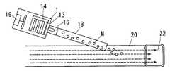
一方、ナノメータサイズの帯電微粒子水(ナノサイズミスト)を発生させる静電霧化装置1は、図3に示すように、この放電電極11を囲む絶縁材からなる筒体16の先端開口部に配設されて上記放電電極11に対向するリング状の対向電極12と、上記放電電極11を冷却することで空気中の水分を放電電極11上に結露させる冷却手段13と、放電電極11と対向電極12との間に高電圧を印加する高圧電源部15とからなるもので、ペルチェ素子で構成されているとともに冷却側に上記放電電極11が熱的に接続されている上記冷却手段13は、その放熱側に放熱フィン14を備えている。 On the other hand, the
また、上記静電霧化装置1は、図1に示すように放熱フィン14に冷却風を送るモータファン18を備えているとともに、このモータファン14から送られる風の一部は上記筒体16の側面開口から筒体16内に入り、筒体16の先端開口である放出口17から吐出される。 Further, as shown in FIG. 1, the
この静電霧化装置1では、冷却手段13で放電電極11を冷却することで空気中の水分を結露させて放電電極11上に結露水を生成するとともに、上記電極11,12間に高電圧を印加すれば、上記結露水は放電電極11の先端に集まるとともに対向電極12との間の放電によってレイリ一分裂を繰り返してナノサイズミストMとなり、上記のモータファン14による風に乗って前記放出口17から外部に吐出される。 In the
ここにおいて、上記静電霧化装置1は、図1に示すように、前記空調装置2における送風路20外に設置されているとともに、上記放出口17に接続された導入管18が送風路20における吹出口22の近傍において送風路20内に入り込んで、導入管20の先端開口が送風路20内における風の流れの方向に向けられている。 Here, as shown in FIG. 1, the
静電霧化装置1が送風路20外にあるために、送風路20を流れる調整された空気の影響を受けることなく結露水を生成してナノサイズミストMを発生させることができるものであり、また放出口17から導入管18を経て送風路20内に入ったナノサイズミストMは、送風路20内を流れる風に乗って吹出口22から車室内に拡散される。 Since the
この時、導入管18の先端開口が送風路20内の風の流れにおける吹出口22の方向に向けられているために、上記風の流れが導入管18の先端開口からのナノサイズミストMの吐出を妨げてしまうようなことがないものであり、特に図1に示すものでは送風路20の断面中央に導入管18の先端を位置させているために、吹出口22まで乱流が発生しにくく、層流となっている風の流れに乗って確実に車室内に吐出される。 At this time, since the front end opening of the
ここにおいて、上記導入管19としては、帯電しにくい材質からなるとともに、車両への設置の都合上、軟質材からなる可撓性を有するもの、たとえばPVCからなるものを用いており、また、内面が滑らかなものを用いている。更に導入管18の両端間は、直線もしくは滑らかな曲線を描くように配置している。導入管18の内面に凹凸があったり、導入管18の途中に直角に折れ曲がった部分があったりすると、導入管18内のナノサイズミストMの流れに乱流が生じて、導入管18の先端開口から吐出されるナノサイズミストMの量が大きく減少してしまうからである。 Here, the
また、導入管18としては、その一端から他端に至るまでの断面積に変化のないものが好ましい。均一な風速で効率良くナノサイズミストMを送ることができるためである。導入管18は50cm以下の長さとすることが、ナノサイズミストMが途中で減少してしまうことを避ける点で好ましい。 In addition, the
さらに導入管18の先端は、図4に示すように、吹出口22の開口面近くに位置させておくと、送風路20を流れる風の風速に影響されることなく安定的にナノサイズミストMを車室内に導くことができる。 Furthermore, as shown in FIG. 4, if the tip of the
図5に示すものは、送風路20の途中に設けた開口35を閉じる蓋36に導入管18を貫通させる貫通部と導入管18の先端を保持する保持リブ37とを設けたものを示している。この保持リブ37は、導入管18が軟質材で形成されている場合にも、送風路20の中央に導入管18を位置させるものとして機能している。 5 shows a structure in which a
図6は送風路20の屈曲部を介して形成された吹出口22の部分の背方に静電霧化装置1を配置したものを示している。導入管18を曲げなくても送風路20の中央に位置させることができる。 FIG. 6 shows a configuration in which the
なお、静電霧化装置1は放電を利用している関係上、その動作時に放電による騒音が発生するが、この音が吹出口22を通じて車室内に漏れてくる場合がある。この点については図7に示すように、外筒と孔明きの内筒との間に吸音材を入れた消音器30を介して導入管18を接続することで対処するのが好ましい。騒音の音漏れを無くすことができる。 Since the
図8に他の例を示す。これは送風路20における導入管18の先端が位置する部分の内径を可変としたもので、導入管18の先端を囲む部分にゴムやウレタンからなる環状の空気袋33を配置し、エアポンプ34から送られる空気によって空気袋33を膨らませたならば、その部分の内径が小さくなるようにしている。 FIG. 8 shows another example. This is because the inner diameter of the portion of the
上記エアポンプ34は、前記ブロアファン23による送風量Vが大である時、送風路20の断面積を大きくし、ブロアファン23による送風量Vが小である時、送風路20の断面積を小さくすることで、送風量が少ない時にも吹出口22から吐出される風の速度を所定値(たとえば0.4m/sec)以上に保って、ナノサイズミストMの車室内への散布効率を高くする。 The
以上の各例では導入管18の先端部を送風路20と平行で且つ送風路20の中央に位置させているものを示したが、図9に示すように送風路20内に導入管18を斜めに差し込んだ形態のものであってもよい。ただし、導入管18の先端開口は吹出口22側を向いたものとする。 In each of the above examples, the tip of the
また、図示例では複数存在している吹出口22のうちの一つに隣接させて静電霧化装置1を設けたものを示したが、複数の吹出口25に夫々隣接させて複数の静電霧化装置1を設けたものであってもよいのはもちろんである。なお、静電霧化装置1を一つだけ設ける場合は、運転席側の吹出口22に設置することが好ましい。運転者が車室内に持ち込んだ臭いやアレル源に対してナノサイズミストMを確実に作用させることができる。 In the illustrated example, the
1 静電霧化装置
2 空調装置
18 導入管
20 送風路
22 吹出口DESCRIPTION OF
Claims (8)
Translated fromJapanesePriority Applications (8)
| Application Number | Priority Date | Filing Date | Title |
|---|---|---|---|
| JP2006213667AJP4396672B2 (en) | 2006-08-04 | 2006-08-04 | Electrostatic atomizer for vehicles |
| EP07792228AEP2046592B1 (en) | 2006-08-04 | 2007-08-02 | Electrostatic atomizing apparatus for use in vehicle |
| US12/375,791US20090321544A1 (en) | 2006-08-04 | 2007-08-02 | Electrostatic atomizing apparatus for use in vehicle |
| AT07792228TATE552995T1 (en) | 2006-08-04 | 2007-08-02 | ELECTROSTATIC ATOMIZATION DEVICE FOR USE IN A VEHICLE |
| PCT/JP2007/065566WO2008016180A1 (en) | 2006-08-04 | 2007-08-02 | Electrostatic atomizing apparatus for use in vehicle |
| CN2007800288074ACN101495334B (en) | 2006-08-04 | 2007-08-02 | Electrostatic atomizing apparatus for use in vehicle |
| HK09108376.8AHK1128663B (en) | 2006-08-04 | 2007-08-02 | Electrostatic atomizing apparatus for use in vehicle |
| US13/177,135US20110259980A1 (en) | 2006-08-04 | 2011-07-06 | Electrostatic atomizing apparatus for use in vehicle |
Applications Claiming Priority (1)
| Application Number | Priority Date | Filing Date | Title |
|---|---|---|---|
| JP2006213667AJP4396672B2 (en) | 2006-08-04 | 2006-08-04 | Electrostatic atomizer for vehicles |
Publications (2)
| Publication Number | Publication Date |
|---|---|
| JP2008037247Atrue JP2008037247A (en) | 2008-02-21 |
| JP4396672B2 JP4396672B2 (en) | 2010-01-13 |
Family
ID=38691107
Family Applications (1)
| Application Number | Title | Priority Date | Filing Date |
|---|---|---|---|
| JP2006213667AActiveJP4396672B2 (en) | 2006-08-04 | 2006-08-04 | Electrostatic atomizer for vehicles |
Country Status (6)
| Country | Link |
|---|---|
| US (2) | US20090321544A1 (en) |
| EP (1) | EP2046592B1 (en) |
| JP (1) | JP4396672B2 (en) |
| CN (1) | CN101495334B (en) |
| AT (1) | ATE552995T1 (en) |
| WO (1) | WO2008016180A1 (en) |
Cited By (18)
| Publication number | Priority date | Publication date | Assignee | Title |
|---|---|---|---|---|
| JP2008094181A (en)* | 2006-10-10 | 2008-04-24 | Japan Climate Systems Corp | Vehicular air-conditioner |
| JP2008189246A (en)* | 2007-02-07 | 2008-08-21 | Calsonic Kansei Corp | Vehicular air conditioner |
| JP2009204229A (en)* | 2008-02-28 | 2009-09-10 | Panasonic Corp | Air conditioner |
| JP2009216313A (en)* | 2008-03-11 | 2009-09-24 | Panasonic Corp | Air conditioner |
| JP2009216312A (en)* | 2008-03-11 | 2009-09-24 | Panasonic Corp | Air conditioner |
| JP2009284989A (en)* | 2008-05-27 | 2009-12-10 | Panasonic Electric Works Co Ltd | Air purifier |
| JP2010006181A (en)* | 2008-06-25 | 2010-01-14 | Panasonic Electric Works Co Ltd | Vehicular ion generating device |
| JP2010017293A (en)* | 2008-07-09 | 2010-01-28 | Panasonic Electric Works Co Ltd | Mist generator |
| JP2010076592A (en)* | 2008-09-25 | 2010-04-08 | Panasonic Electric Works Co Ltd | Electrostatically atomizing system for vehicle |
| WO2010150770A1 (en)* | 2009-06-26 | 2010-12-29 | パナソニック電工株式会社 | Air blowing device |
| JP2011038747A (en)* | 2009-08-18 | 2011-02-24 | Panasonic Electric Works Co Ltd | Blower including discharge device |
| EP2301780A1 (en) | 2009-09-29 | 2011-03-30 | Panasonic Electric Works Co., Ltd. | Blowing device including an electrostatic atomizer |
| JP2011200823A (en)* | 2010-03-26 | 2011-10-13 | Panasonic Electric Works Co Ltd | Electrostatic atomizer |
| JP2012180017A (en)* | 2011-03-01 | 2012-09-20 | Inoac Corp | Duct equipment |
| JP2014169860A (en)* | 2011-07-27 | 2014-09-18 | Dyson Technology Ltd | Fan assembly |
| US9458853B2 (en) | 2011-07-27 | 2016-10-04 | Dyson Technology Limited | Fan assembly |
| JP2017043110A (en)* | 2015-08-24 | 2017-03-02 | 株式会社豊田中央研究所 | Functional ingredient transport device |
| JP7168891B1 (en) | 2021-08-06 | 2022-11-10 | ダイキン工業株式会社 | air conditioning indoor unit |
Families Citing this family (19)
| Publication number | Priority date | Publication date | Assignee | Title |
|---|---|---|---|---|
| WO2005102101A1 (en)* | 2004-04-23 | 2005-11-03 | Matsushita Electric Works, Ltd. | Fan heater with electrostatic atomizer |
| US20100323602A1 (en)* | 2007-02-07 | 2010-12-23 | Nobuyasu Suematsu | Air conditioning apparatus for vehicle |
| JP5249648B2 (en)* | 2008-06-25 | 2013-07-31 | パナソニック株式会社 | Electrostatic atomizer for vehicles |
| JP5149095B2 (en)* | 2008-07-28 | 2013-02-20 | パナソニック株式会社 | Electrostatic atomizer and air conditioner using the same |
| JP2010091263A (en)* | 2008-09-11 | 2010-04-22 | Panasonic Corp | Air conditioner |
| CN101700206B (en)* | 2009-07-07 | 2012-07-18 | 松下电器产业株式会社 | Spray generating device |
| JP2011025204A (en)* | 2009-07-28 | 2011-02-10 | Panasonic Electric Works Co Ltd | Electrostatic atomizer |
| JP5603187B2 (en)* | 2010-09-24 | 2014-10-08 | パナソニック株式会社 | Electrostatic atomization system for vehicles |
| USD681571S1 (en)* | 2010-09-29 | 2013-05-07 | Panasonic Corporation | Electrode |
| USD681572S1 (en)* | 2010-09-29 | 2013-05-07 | Panasonic Corporation | Electrode |
| JP1434985S (en)* | 2011-04-21 | 2015-02-23 | ||
| AR082603A1 (en)* | 2011-08-09 | 2012-12-19 | Lavaque Oscar | A CARBON DIOXIDE SOLUBILIZING DEVICE IN A VARIABLE PRESSURE DRINK |
| US9815557B2 (en)* | 2012-09-20 | 2017-11-14 | Humbay Health, LLC | Aircraft humidifier |
| US9847623B2 (en) | 2014-12-24 | 2017-12-19 | Plasma Air International, Inc | Ion generating device enclosure |
| US9660425B1 (en) | 2015-12-30 | 2017-05-23 | Plasma Air International, Inc | Ion generator device support |
| GB2547474B (en)* | 2016-02-22 | 2019-01-23 | Jaguar Land Rover Ltd | Ionized air delivery system |
| JP6684999B2 (en) | 2016-08-30 | 2020-04-22 | パナソニックIpマネジメント株式会社 | Blower with discharge device |
| DE102017008715A1 (en) | 2017-09-16 | 2018-03-22 | Daimler Ag | Atomizing device for an interior of a motor vehicle, in particular a passenger car |
| US11353238B2 (en)* | 2018-09-21 | 2022-06-07 | Gas Technology Institute | Ultrasonic condensate neutralization and disposal system |
Citations (5)
| Publication number | Priority date | Publication date | Assignee | Title |
|---|---|---|---|---|
| JPS63110112U (en)* | 1987-01-12 | 1988-07-15 | ||
| JPH06115347A (en)* | 1992-10-02 | 1994-04-26 | Nippondenso Co Ltd | Air conditioner |
| JP2005131549A (en)* | 2003-10-30 | 2005-05-26 | Matsushita Electric Works Ltd | Electrostatic atomization apparatus |
| JP2005296753A (en)* | 2004-04-08 | 2005-10-27 | Matsushita Electric Works Ltd | Electrostatic atomizing device |
| JP2007163109A (en)* | 2005-12-16 | 2007-06-28 | Matsushita Electric Works Ltd | Air conditioner provided with electrostatic atomization device |
Family Cites Families (9)
| Publication number | Priority date | Publication date | Assignee | Title |
|---|---|---|---|---|
| JPS62155122A (en)* | 1985-12-27 | 1987-07-10 | Hitachi Ltd | Automotive air conditioner |
| CN2175135Y (en)* | 1993-08-30 | 1994-08-24 | 潍坊市电磁科研所 | Device for keeping fresh air for vehicles |
| JP2706912B2 (en)* | 1995-09-22 | 1998-01-28 | 東拓工業株式会社 | Insulated silencer duct |
| US6062270A (en)* | 1997-01-27 | 2000-05-16 | Lindab Ab | Double-walled structure in a ventilation duct system |
| JP2005289177A (en)* | 2004-03-31 | 2005-10-20 | Calsonic Kansei Corp | Air conditioner |
| US7874503B2 (en)* | 2004-04-08 | 2011-01-25 | Panasonic Electric Works Co., Ltd. | Electrostatcially atomizing device |
| KR100707845B1 (en)* | 2004-09-27 | 2007-04-13 | 마츠시다 덴코 가부시키가이샤 | Electrostatic atomizing hairdryer |
| JP4470710B2 (en)* | 2004-11-25 | 2010-06-02 | パナソニック電工株式会社 | Air conditioner for vehicles |
| DE602006016018D1 (en)* | 2005-12-16 | 2010-09-16 | Panasonic Elec Works Co Ltd | AIR CONDITIONING WITH ELECTROSTATIC SPRAYING FUNCTION |
- 2006
- 2006-08-04JPJP2006213667Apatent/JP4396672B2/enactiveActive
- 2007
- 2007-08-02USUS12/375,791patent/US20090321544A1/ennot_activeAbandoned
- 2007-08-02ATAT07792228Tpatent/ATE552995T1/enactive
- 2007-08-02CNCN2007800288074Apatent/CN101495334B/enactiveActive
- 2007-08-02WOPCT/JP2007/065566patent/WO2008016180A1/enactiveApplication Filing
- 2007-08-02EPEP07792228Apatent/EP2046592B1/enactiveActive
- 2011
- 2011-07-06USUS13/177,135patent/US20110259980A1/ennot_activeAbandoned
Patent Citations (5)
| Publication number | Priority date | Publication date | Assignee | Title |
|---|---|---|---|---|
| JPS63110112U (en)* | 1987-01-12 | 1988-07-15 | ||
| JPH06115347A (en)* | 1992-10-02 | 1994-04-26 | Nippondenso Co Ltd | Air conditioner |
| JP2005131549A (en)* | 2003-10-30 | 2005-05-26 | Matsushita Electric Works Ltd | Electrostatic atomization apparatus |
| JP2005296753A (en)* | 2004-04-08 | 2005-10-27 | Matsushita Electric Works Ltd | Electrostatic atomizing device |
| JP2007163109A (en)* | 2005-12-16 | 2007-06-28 | Matsushita Electric Works Ltd | Air conditioner provided with electrostatic atomization device |
Cited By (29)
| Publication number | Priority date | Publication date | Assignee | Title |
|---|---|---|---|---|
| JP2008094181A (en)* | 2006-10-10 | 2008-04-24 | Japan Climate Systems Corp | Vehicular air-conditioner |
| JP2008189246A (en)* | 2007-02-07 | 2008-08-21 | Calsonic Kansei Corp | Vehicular air conditioner |
| JP2009204229A (en)* | 2008-02-28 | 2009-09-10 | Panasonic Corp | Air conditioner |
| JP2009216313A (en)* | 2008-03-11 | 2009-09-24 | Panasonic Corp | Air conditioner |
| JP2009216312A (en)* | 2008-03-11 | 2009-09-24 | Panasonic Corp | Air conditioner |
| JP2009284989A (en)* | 2008-05-27 | 2009-12-10 | Panasonic Electric Works Co Ltd | Air purifier |
| JP2010006181A (en)* | 2008-06-25 | 2010-01-14 | Panasonic Electric Works Co Ltd | Vehicular ion generating device |
| JP2010017293A (en)* | 2008-07-09 | 2010-01-28 | Panasonic Electric Works Co Ltd | Mist generator |
| JP2010076592A (en)* | 2008-09-25 | 2010-04-08 | Panasonic Electric Works Co Ltd | Electrostatically atomizing system for vehicle |
| US8241407B2 (en) | 2008-09-25 | 2012-08-14 | Panasonic Corporation | Electrostatically atomizing kit for use in a vehicle |
| WO2010150770A1 (en)* | 2009-06-26 | 2010-12-29 | パナソニック電工株式会社 | Air blowing device |
| JP2011007443A (en)* | 2009-06-26 | 2011-01-13 | Panasonic Electric Works Co Ltd | Air blower including electrostatic atomizer |
| JP2011038747A (en)* | 2009-08-18 | 2011-02-24 | Panasonic Electric Works Co Ltd | Blower including discharge device |
| WO2011021708A1 (en) | 2009-08-18 | 2011-02-24 | Panasonic Electric Works Co., Ltd. | Blower including discharge device |
| EP2301780A1 (en) | 2009-09-29 | 2011-03-30 | Panasonic Electric Works Co., Ltd. | Blowing device including an electrostatic atomizer |
| JP2011200823A (en)* | 2010-03-26 | 2011-10-13 | Panasonic Electric Works Co Ltd | Electrostatic atomizer |
| JP2012180017A (en)* | 2011-03-01 | 2012-09-20 | Inoac Corp | Duct equipment |
| US10094581B2 (en) | 2011-07-27 | 2018-10-09 | Dyson Technology Limited | Fan assembly |
| JP2014169860A (en)* | 2011-07-27 | 2014-09-18 | Dyson Technology Ltd | Fan assembly |
| US9127855B2 (en) | 2011-07-27 | 2015-09-08 | Dyson Technology Limited | Fan assembly |
| US9291361B2 (en) | 2011-07-27 | 2016-03-22 | Dyson Technology Limited | Fan assembly |
| US9335064B2 (en) | 2011-07-27 | 2016-05-10 | Dyson Technology Limited | Fan assembly |
| US9458853B2 (en) | 2011-07-27 | 2016-10-04 | Dyson Technology Limited | Fan assembly |
| JP2017043110A (en)* | 2015-08-24 | 2017-03-02 | 株式会社豊田中央研究所 | Functional ingredient transport device |
| JP7168891B1 (en) | 2021-08-06 | 2022-11-10 | ダイキン工業株式会社 | air conditioning indoor unit |
| WO2023013582A1 (en)* | 2021-08-06 | 2023-02-09 | ダイキン工業株式会社 | Air-conditioning indoor unit |
| JP2023024123A (en)* | 2021-08-06 | 2023-02-16 | ダイキン工業株式会社 | Air-conditioning indoor unit |
| JP2023024426A (en)* | 2021-08-06 | 2023-02-16 | ダイキン工業株式会社 | air conditioning indoor unit |
| JP7617444B2 (en) | 2021-08-06 | 2025-01-20 | ダイキン工業株式会社 | Air conditioning indoor unit |
Also Published As
| Publication number | Publication date |
|---|---|
| WO2008016180A1 (en) | 2008-02-07 |
| US20090321544A1 (en) | 2009-12-31 |
| EP2046592B1 (en) | 2012-04-11 |
| CN101495334A (en) | 2009-07-29 |
| US20110259980A1 (en) | 2011-10-27 |
| CN101495334B (en) | 2011-05-11 |
| HK1128663A1 (en) | 2009-11-06 |
| EP2046592A1 (en) | 2009-04-15 |
| JP4396672B2 (en) | 2010-01-13 |
| ATE552995T1 (en) | 2012-04-15 |
Similar Documents
| Publication | Publication Date | Title |
|---|---|---|
| JP4396672B2 (en) | Electrostatic atomizer for vehicles | |
| JP4492602B2 (en) | Electrostatic atomizer for vehicles | |
| JP4333779B2 (en) | Blower | |
| JP4470710B2 (en) | Air conditioner for vehicles | |
| JP4864753B2 (en) | Air conditioner for vehicles | |
| WO2007069577A1 (en) | Air conditioning system with electrostatic atomizing function | |
| JP2011038747A (en) | Blower including discharge device | |
| JP5038800B2 (en) | In-vehicle air conditioner | |
| JP2011007443A (en) | Air blower including electrostatic atomizer | |
| JP2007163109A (en) | Air conditioner provided with electrostatic atomization device | |
| US20110073685A1 (en) | Blowing device including an electrostatic atomizer | |
| JP4948108B2 (en) | Air conditioner for vehicles | |
| JP5060445B2 (en) | Electrostatic atomization system for vehicles | |
| JP4824520B2 (en) | Electrostatic atomizer | |
| JP4966169B2 (en) | Blower | |
| JP4881181B2 (en) | Vehicle purification device | |
| JP5411881B2 (en) | Air conditioner with electrostatic atomizer | |
| JP4492531B2 (en) | Air conditioner with electrostatic atomizer | |
| JP2008087636A (en) | Air conditioner | |
| HK1128663B (en) | Electrostatic atomizing apparatus for use in vehicle | |
| HK1141494B (en) | Electrostatically atomizing kit for use in a vehicle | |
| JP2008087637A (en) | Electrostatic fine particle water supply device | |
| HK1124652B (en) | Blower apparatus |
Legal Events
| Date | Code | Title | Description |
|---|---|---|---|
| A621 | Written request for application examination | Free format text:JAPANESE INTERMEDIATE CODE: A621 Effective date:20080213 | |
| A131 | Notification of reasons for refusal | Free format text:JAPANESE INTERMEDIATE CODE: A131 Effective date:20090512 | |
| A521 | Request for written amendment filed | Free format text:JAPANESE INTERMEDIATE CODE: A523 Effective date:20090713 | |
| TRDD | Decision of grant or rejection written | ||
| A01 | Written decision to grant a patent or to grant a registration (utility model) | Free format text:JAPANESE INTERMEDIATE CODE: A01 Effective date:20090929 | |
| A01 | Written decision to grant a patent or to grant a registration (utility model) | Free format text:JAPANESE INTERMEDIATE CODE: A01 | |
| A61 | First payment of annual fees (during grant procedure) | Free format text:JAPANESE INTERMEDIATE CODE: A61 Effective date:20091012 | |
| FPAY | Renewal fee payment (event date is renewal date of database) | Free format text:PAYMENT UNTIL: 20121030 Year of fee payment:3 | |
| R151 | Written notification of patent or utility model registration | Ref document number:4396672 Country of ref document:JP Free format text:JAPANESE INTERMEDIATE CODE: R151 | |
| FPAY | Renewal fee payment (event date is renewal date of database) | Free format text:PAYMENT UNTIL: 20131030 Year of fee payment:4 |