JP2008036767A - Assembling device of roller tappet and assembling method thereof - Google Patents
Assembling device of roller tappet and assembling method thereofDownload PDFInfo
- Publication number
- JP2008036767A JP2008036767AJP2006213936AJP2006213936AJP2008036767AJP 2008036767 AJP2008036767 AJP 2008036767AJP 2006213936 AJP2006213936 AJP 2006213936AJP 2006213936 AJP2006213936 AJP 2006213936AJP 2008036767 AJP2008036767 AJP 2008036767A
- Authority
- JP
- Japan
- Prior art keywords
- tappet
- roller
- press
- pin
- stopper member
- Prior art date
- Legal status (The legal status is an assumption and is not a legal conclusion. Google has not performed a legal analysis and makes no representation as to the accuracy of the status listed.)
- Withdrawn
Links
- 238000000034methodMethods0.000titleclaimsabstractdescription28
- 238000003780insertionMethods0.000claimsdescription10
- 230000037431insertionEffects0.000claimsdescription10
- 230000002265preventionEffects0.000claimsdescription10
- 238000000605extractionMethods0.000claims1
- 230000000694effectsEffects0.000description1
Images


Landscapes
- Automatic Assembly (AREA)
Abstract
Description
Translated fromJapanese本発明はエンジン用ローラタペットの組立作業に適用され、基台上に固定可能にされたVブロックのV字状支持面上にローラタペットのタペット本体を載置し、該タペット本体のピン穴に、ローラが嵌装されたローラピンをプレス機械の圧入工具により圧入して該ローラピンをタペット本体に固定するように構成されたローラタペットの組立装置及び該ローラタペットの組立方法に関する。 The present invention is applied to an assembling operation of a roller tappet for an engine. A tappet body of a roller tappet is placed on a V-shaped support surface of a V block which can be fixed on a base. The present invention relates to a roller tappet assembling apparatus configured to press-fit a roller pin fitted with a roller by a press-fitting tool of a press machine and fix the roller pin to a tappet body, and a method of assembling the roller tappet.
図6はエンジン用ローラタペットの構造を示し、(A)はタペット本体の軸心線及びローラピンの軸心線に沿う一部断面図((B)におけるZ−Z線断面図)、(B)は(A)におけるY矢視図である。
図6において、100はローラタペットで、円筒状のタペット本体101、該タペット本体101のスカート部101dのピン穴101bに圧入されたローラピン104、該ローラピン104の中央部に軸受105を介して回転自在に支持されたローラ103等よりなる。100aはローラ103を収納する空間である。6A and 6B show the structure of the roller tappet for an engine, and FIG. 6A is a partial sectional view taken along the axis of the tappet body and the axis of the roller pin (a sectional view taken along the line ZZ in FIG. 6B). These are the Y arrow line views in (A).
In FIG. 6,
図7は前記ローラタペットにおけるタペット本体へのローラピン104の組付け手段の従来の一例を示すローラピン104の軸心104Xに沿う断面図である。
図7において、3はベースプレート(基台)、1は該ベースプレート3上に固定可能にされたVブロック、200は油圧プレス、201は該油圧プレス200の圧入工具、202はベースプレート3を載置する油圧プレス200のテーブルである。
前記ローラタペット100を組み立てるにあたっては、タペット本体101のローラ収納空間100aに、軸受105を介してローラ103を支持した状態で挿入し、さらにローラピン104を前記スカート部101dのピン穴101bに挿入することにより、ローラタペット100が仮組立状態となる。さらに前記タペット本体101の弦月状断面からなるスカート端部101aに形成されて前記ローラ103の両側面に対向する2つの対向内面101c,101c間に治具204(二点鎖線で示す)を挿入して前記スカート端部101aの変形予防処置を施して、前記治具付きのローラタペット100の仮組立品を製作し、この仮組立品を、該タペット本体101の長手方向の軸心101Zを前記Vブロック1のV字状支持面1aと平行にして該V字状支持面1a上に載置する。FIG. 7 is a cross-sectional view along the
In FIG. 7, 3 is a base plate (base), 1 is a V block that can be fixed on the
When assembling the roller tappet 100, the
次いで、前記ローラピン104の軸心104Xが前記圧入工具201の軸心201Xに一致しているかを目視で確認し、一致したら、前記油圧プレス200を運転して、前記圧入工具201により前記ローラピン104を押圧して前記タペット本体101のピン穴101bに圧入する。この際において、図示しない圧力ゲージによって前記圧入工具201による押圧油圧を測定しながら、一定の目標油圧で前記ローラピン104を前記ピン穴101bに圧入する。
このとき、前記2つの対向内面101c,101c間に前記治具204を挿入しているので、前記圧入工具201によるローラピン104の圧入時に剛性の小さいスカート端部101aに圧入工具201が接触して、ローラ103の側面103aと前記対向内面101c,101cとが変形するのを防止する。
かかるローラピン104の圧入工程終了後、前記治具204を前記対向内面101c,101c間から引き抜くことでタペットの組立工程が終了する。Next, it is visually confirmed whether the
At this time, since the
After the press-fitting process of the
尚、特許文献1(特開平9−131626号公報)には、ワーク53を可動治具1によって保持し、センタリング部材Cによって該可動治具1を介してワーク53のセンタリングを行ない、プレス機械の圧入部材55とワーク53の圧入孔53aとの長手軸心線Xを自動的に同心に配置することにより、偏心した場合の荷重による圧入部材55の変形を抑えるようにした、プレス圧入機によるワーク支持装置が開示されている。 In Patent Document 1 (Japanese Patent Application Laid-Open No. 9-131626), the work 53 is held by the
図7に示されるような、従来のローラタペット組立方法では、前記のように、
(1)いわゆる外段取り工程にてタペット本体101のローラ収納空間100aに、軸受105を介してローラ103を支持した状態で挿入し、さらにローラピン104を前記スカート部101dのピン穴101bに挿入することにより、ローラタペット100を仮組立状態とし、該ローラタペット100の仮組立状態のスカート端部101aの2つの対向内面101c、101c間に圧入時の変形を防止する治具を挿入して製作する外段取り工程と、
(2)この治具付きのローラタペットの仮組立品をVブロック1のV字状支持面1a上に載置し、ローラピン104の軸心104Xが油圧プレス200の圧入工具201の軸心201Xに一致しているかを目視で確認し、一致したら治具によりスカート端部101aの変形を防止しつつタペット本体101のピン穴101bに圧入し、かかるローラピン104の圧入工程終了後、治具を前記対向内面101c,101c間から引き抜く、というローラタペットの本組付け工程
の2つの工程によってローラタペットを組立てている。In the conventional roller tappet assembly method as shown in FIG.
(1) Insert the
(2) The roller tappet temporary assembly with the jig is placed on the V-
このため、かかる従来のローラタペット組立方法にあっては、油圧プレス200のベースプレート3及びVブロック1上において圧入工具201によりローラピン104をタペット本体101のピン穴101bに圧入する本組付け工程とは別にタペット本体に治具を挿入した仮組立品の外段取り工程を行ない、この仮組立品を油圧プレス200のベースプレート3及びVブロック1上に搬入して取付けるという、余分な工程を必要とするため、ローラタペット100の組立に多くの工数を必要とする。 Therefore, in this conventional roller tappet assembly method, what is the main assembly process of press-fitting the
本発明はかかる従来技術の課題に鑑み、ローラタペットを組立てるに際し、ローラピンをタペット本体に組付けるための外段取り工程を不要として、油圧プレス機械上におけるベースプレートとVブロックとタペット本体の夫々の軸心を一致させる位置決め機能を持たせ、且つローラピン組付け時のスカート端部の変形を防止しつつローラタペットの組立を可能としたローラタペットの組立装置及び組立方法を提供することを目的とする。 In view of the problems of the prior art, the present invention eliminates the need for an external setup step for assembling the roller pin to the tappet body when assembling the roller tappet, and the shaft centers of the base plate, the V block, and the tappet body on the hydraulic press machine. Another object of the present invention is to provide a roller tappet assembling apparatus and a method for assembling a roller tappet that have a positioning function for matching the roller pins and prevent deformation of the skirt end when the roller pin is assembled.
本発明はかかる目的を達成するもので、基台上に固定可能にされたVブロックのV字状支持面上にローラタペットのタペット本体を載置し、該タペット本体のピン穴に、ローラが嵌装されたローラピンをプレス機械に装着された圧入工具により圧入して該ローラピンをタペット本体に固定するように構成されたローラタペットの組立装置において、前記基台を前記プレス機械のテーブル上に位置決めして前記Vブロック上に載置された前記タペット本体のピン穴の中心と前記圧入工具の中心とを位置決めする位置決め機構と、前記タペット本体のスカート端部に形成され前記ローラの両側面に対向する2つの対向内面間に挿入あるいは抜き出し可能なストッパー部材と、該ストッパー部材を前記対向内面間に進退可能に支持する支持体とをそなえて、前記ストッパー部材を前記対向内面間に挿入することによりタペット本体がVブロック上に正確に水平方向に載置されるようにすると共に、前記圧入工具による前記ローラピンの前記タペット本体のピン穴への圧入時における前記スカート端部の変形を阻止する変形防止治具を前記基台上に取り付けたことを特徴とする(請求項1)。 The present invention achieves such an object. A tappet body of a roller tappet is placed on a V-shaped support surface of a V block that can be fixed on a base, and a roller is placed in a pin hole of the tappet body. In a roller tappet assembly device configured to press-fit a fitted roller pin with a press-fit tool attached to a press machine and fix the roller pin to a tappet body, the base is positioned on a table of the press machine. And a positioning mechanism for positioning the center of the pin hole of the tappet body placed on the V block and the center of the press-fitting tool, and opposed to both side surfaces of the roller formed at the skirt end portion of the tappet body. A stopper member that can be inserted or removed between the two opposing inner surfaces, and a support body that supports the stopper member so as to be able to advance and retract between the opposing inner surfaces. In addition, by inserting the stopper member between the opposed inner surfaces, the tappet main body is placed on the V block accurately in the horizontal direction, and the roller pin by the press-fitting tool is inserted into the pin hole of the tappet main body. A deformation preventing jig for preventing deformation of the skirt end during press-fitting is attached to the base (claim 1).
また、前記組立装置を用いてのローラタペットの組立方法に関する発明は、基台上に固定可能にされたVブロックのV字状支持面上にローラタペットのタペット本体を載置し、該タペット本体のピン穴に、ローラが嵌装されたローラピンをプレス機械に装着された圧入工具により圧入して該ローラピンをタペット本体に固定するローラタペットの組立方法であって、前記プレス機械のテーブル上に該プレス機械の圧入工具と同心に立設された位置決めピンに、前記基台に穿孔された位置決めピン穴を嵌合して前記基台を前記プレス機械のテーブル上に載置して固定し、前記基台に固定された前記VブロックのV字状支持面上に前記ローラタペットのタペット本体を載置し、タペット位置調整手段を用いて前記タペット本体のピン穴の中心と前記圧入工具の軸心とが同心になるようにタペット本体位置を調整し、前記タペット本体のスカート端部に形成され前記ローラの両側面に対向する2つの対向内面間にストッパー部材を挿入してタペット本体がVブロック上に、正確に水平方向に載置すると共に、該ストッパー部材の表面を2つの対向内面に当接させた状態で、前記プレス機械の圧入工具により前記ローラピンを押圧して前記タペット本体のピン穴に圧入することを特徴とする(請求項6)。 The invention relating to a method for assembling a roller tappet using the assembling apparatus further comprises: placing a tappet body of a roller tappet on a V-shaped support surface of a V block which can be fixed on a base; A roller tappet assembling method in which a roller pin fitted with a roller is press-fitted into a pin hole by a press-fitting tool attached to a press machine and the roller pin is fixed to the tappet body. A positioning pin hole drilled in the base is fitted to a positioning pin erected concentrically with the press-fitting tool of the press machine, and the base is placed on the table of the press machine and fixed, The tappet body of the roller tappet is placed on the V-shaped support surface of the V block fixed to the base, and the center and front of the pin hole of the tappet body are adjusted using the tappet position adjusting means. The tappet body position is adjusted so that the shaft center of the press-fitting tool is concentric, and a stopper member is inserted between two opposed inner surfaces formed on the skirt end portion of the tappet body and opposed to both side surfaces of the roller. The main body is placed on the V block in the horizontal direction and the roller pin is pressed by the press-fitting tool of the press machine while the surface of the stopper member is in contact with two opposing inner surfaces. It is press-fitted into the pin hole of the main body (claim 6).
かかる発明によれば、プレス機械のテーブル上に圧入工具と同心に位置決めピンを立設し、該位置決めピンを用いてタペット本体が載置されるVブロックが固定された基台をテーブル上に位置決めして固定し、タペット本体のピン穴中心と圧入工具の軸心とが同心になるようにタペット本体の位置を調整することによりVブロック上での位置決めを行ない、且つタペット本体の変形防止治具のストッパー部材をスカート端部の2つの対向内面間に挿入して該対向内面に当接させ、前記プレス機械の圧入工具によりローラピンをタペット本体のピン穴に圧入する、というプレス機械のテーブル上に載置される基台及びVブロック上での一つの工程でローラタペットを組立てることができる。 According to this invention, a positioning pin is erected concentrically with the press-fitting tool on the table of the press machine, and the base on which the V block on which the tappet body is placed is fixed is positioned on the table using the positioning pin. The position of the tappet body is adjusted so that the center of the pin hole of the tappet body and the axis of the press-fitting tool are concentric, and positioning on the V block is performed. On the table of the press machine, the stopper member is inserted between the two facing inner surfaces of the skirt end, brought into contact with the facing inner surface, and the roller pin is press-fitted into the pin hole of the tappet body by the press-fitting tool of the press machine. The roller tappet can be assembled in one step on the base and V block to be placed.
これにより、従来技術のようなベースプレート及びVブロック上での圧入工具によるローラピンのタペット本体のピン穴への圧入工程(本組付け工程)の前における、油圧プレスの機外でのローラタペットのスカート部端部の2つの対向内面間に圧入時の変形を防止するための治具を挿入した仮組立品の仮組立てという外段取り工程が不要となり、ローラピンのタペット本体への組付け時のスカート端部の変形を防止しつつ、従来技術に比べてローラタペットの組立工数を大幅に低減できる。
また、ベースプレート上に設置した変形防止治具を用いてタペット本体の位置決めと、該変形防止治具によるスカート端部の変形を防止しつつ、圧入工具によるローラピンのタペット本体のピン穴への圧入作業を、ワーク及び作業治具及び工具を取外すことなく連続して実施できるので、ローラピンのタペット本体のピン穴への圧入作業を高精度でかつ迅速に行なうことができ、ローラタペットの組立作業効率が向上する。As a result, the roller tappet skirt outside the machine of the hydraulic press before the press-fitting process (main assembly process) of the roller pins into the tap holes of the tappet body by the press-fitting tool on the base plate and the V block as in the prior art. The skirt end when assembling the roller pin to the tappet body is eliminated, as the temporary assembly of the temporary assembly with a jig for preventing deformation during press-fitting is inserted between the two opposing inner surfaces of the end part The number of assembling steps of the roller tappet can be greatly reduced as compared with the prior art while preventing the deformation of the portion.
Also, the tappet body is positioned using the deformation prevention jig installed on the base plate, and the press-fitting tool press-fits the roller pin into the pin hole of the tappet body while preventing the deformation of the skirt end. Can be carried out continuously without removing the workpiece, work jig and tool, so that the press-fitting work of the roller pin into the pin hole of the tappet body can be performed with high accuracy and speed, and the assembly work efficiency of the roller tappet is improved. improves.
かかる発明において、好ましくは、前記位置決め機構は、前記プレス機械のテーブル上に該プレス機械の圧入工具と同心に立設されて、前記基台に穿孔された位置決めピン穴に嵌合される位置決めピンの軸心と、前記Vブロック上に載置された前記タペット本体のピン穴の中心と、前記圧入工具の軸心とが同心になるように前記タペット本体位置を調整するタペット位置調整手段とをそなえる(請求項2)。
このような構成にすれば、位置決めピンに基台を位置決めし、基台上に固定されたVブロック上に載置されたタペット本体の位置を位置決めすることにより、圧入工具の軸心とタペット本体のピン穴中心とを容易に、且つ精度良く一致させることができる。In this invention, preferably, the positioning mechanism is erected on a table of the press machine concentrically with the press-fitting tool of the press machine and is fitted into a positioning pin hole drilled in the base. A tappet position adjusting means for adjusting the position of the tappet body so that the center of the pin hole of the tappet body placed on the V block is concentric with the axis of the press-fitting tool. Provided (Claim 2).
With this configuration, the base of the press-fitting tool and the tappet main body are positioned by positioning the base on the positioning pins and positioning the tappet main body placed on the V block fixed on the base. The center of the pin hole can be easily and accurately matched.
また、かかる発明において、前記変形防止治具を具体的にはつぎのように構成する。
(1)前記変形防止治具は、前記ストッパー部材の軸心を前記タペット本体のピン穴中心に対する開き角が略直角になるように前記基台上に2個設置し、前記タペット本体の対向内面間の2箇所に前記ストッパー部材を挿入可能に構成される(請求項3)。
このように構成すれば、2個の変形防止治具のストッパー部材を軸心の開き角が略直角になるように配置することにより、該ストッパー部材をスカート端部のローラの両側面への2つの対向内面間に挿入する際に、該ストッパー部材の先端部がローラの外周に接触することなく且つ前記対向内面とストッパー部材との接触面積を最も大きくとることができるため、圧入工具によるローラピンのタペット本体ピン穴への圧入時におけるスカート端部の変形防止効果を最も大きく得ることができる。In this invention, the deformation preventing jig is specifically configured as follows.
(1) Two deformation prevention jigs are installed on the base so that an opening angle of the stopper member with respect to the pin hole center of the tappet body is substantially a right angle. The stopper member is configured to be insertable at two positions therebetween (Claim 3).
According to this structure, the stopper members of the two deformation prevention jigs are arranged so that the opening angle of the shaft center is substantially perpendicular, so that the stopper members are placed on both sides of the roller at the end of the skirt. When inserting between the two opposing inner surfaces, the tip of the stopper member does not contact the outer periphery of the roller, and the contact area between the opposing inner surface and the stopper member can be maximized. The greatest effect of preventing deformation of the skirt end at the time of press-fitting into the tappet body pin hole can be obtained.
(2)前記変形防止治具は、前記基台上に立設されて前記支持体を上下移動可能に且つ相対回転不能に嵌合して支持する支柱をそなえるとともに、前記ストッパー部材と前記支持体とをねじ結合して該ねじにより前記タペット本体の対向内面間に挿入あるいは抜き出し可能とし、前記支持体を前記支柱との嵌合部に沿って上下動せしめることにより前記ストッパー部材と前記タペット本体の対向内面との高さを調整し、前記ストッパー部材の支持体へのねじ込み量により前記タペット本体の対向内面間への挿入量を調整するように構成される(請求項4)。
このように構成すれば、基台上に立設され支柱に沿ってストッパー部材の支持体を自在に上下動できるとともに、ストッパー部材の該支持体へのねじ込み量を変化させることによりストッパー部材のタペット本体の対向内面間への挿入量を容易に調整でき、該ストッパー部材の先端部位置の前記対向内面間への挿入量調整を容易に且つ高精度で行なうことができる。(2) The deformation preventing jig includes a column which is erected on the base so as to fit and support the support body so that the support body can be moved up and down and cannot be relatively rotated, and the stopper member and the support body Are connected to the inner surface of the tappet body by the screws, and the support member is moved up and down along the fitting portion with the support column to thereby remove the stopper member and the tappet body. The height with respect to the opposing inner surface is adjusted, and the amount of insertion between the opposing inner surfaces of the tappet body is adjusted by the screwing amount of the stopper member into the support (claim 4).
If comprised in this way, while being able to move up and down freely the support body of a stopper member standing on a base and along a support | pillar, the tappet of a stopper member can be changed by changing the screwing amount of the stopper member to this support body The insertion amount between the opposing inner surfaces of the main body can be easily adjusted, and the insertion amount adjustment between the opposing inner surfaces at the position of the tip of the stopper member can be easily performed with high accuracy.
(3)前記変形防止治具は、前記ストッパー部材の先端部を構成するストッパーピースの前記タペット本体の対向内面間への挿入部を該対向内面間に嵌合可能なテーパ状に形成してなる(請求項5)。
このように構成すれば、ストッパーピースのタペット本体の対向内面間への挿入時に、該対向内面間の距離に公差があっても、該公差に応じてストッパー部材のテーパ状先端部の押し込み代を調整することにより、ストッパー部材を前記対向内面間に確実に嵌合できる。
また、タペット本体の長手方向の軸心がVブロックのV字状支持面上に平行に載置されなかった場合、2個のストッパー部材のテーパ部が対向内面間に嵌挿され、スカート部の端部が略平行な位置に調整されることにより、油圧プレスの圧入工具がスカート部に接触しないため、変形を防止することができる。(3) The deformation preventing jig is formed such that a stopper piece constituting the distal end portion of the stopper member is inserted into a portion between the opposed inner surfaces of the tappet body in a tapered shape that can be fitted between the opposed inner surfaces. (Claim 5).
According to this configuration, when the stopper piece is inserted between the opposing inner surfaces of the tappet body, even if there is a tolerance in the distance between the opposing inner surfaces, the pushing margin of the tapered tip end portion of the stopper member is set according to the tolerance. By adjusting, the stopper member can be reliably fitted between the opposed inner surfaces.
Further, when the longitudinal axis of the tappet body is not placed in parallel on the V-shaped support surface of the V block, the taper portions of the two stopper members are fitted between the opposing inner surfaces, and the skirt portion By adjusting the end portion to a substantially parallel position, the press-fitting tool of the hydraulic press does not contact the skirt portion, so that deformation can be prevented.
本発明によれば、プレス機械のテーブル上に圧入工具と同心に位置決めピンを立設し、該位置決めピンを用いてタペット本体が載置されるVブロックが固定された基台をテーブル上に位置決めして固定し、タペット本体のピン穴中心と圧入工具の軸心とが同心になるようにタペット本体の位置を調整することによりVブロック上での位置決めを行ない、且つタペット本体の変形防止治具のストッパー部材をスカート端部の2つの対向内面間に挿入して該対向内面に当接させ、前記プレス機械の圧入工具によりローラピンをタペット本体のピン穴に圧入する、というプレス機械のテーブル上に載置される基台及びVブロック上での一つの工程でローラタペットを組立てることができる。
これにより、従来技術のようなベースプレート及びVブロック上での圧入工具によるローラピンのタペット本体のピン穴への圧入工程(本組付け工程)の前における、油圧プレスの機外でのローラタペットのスカート部端部の2つの対向内面間に圧入時の変形を防止するための治具を挿入した仮組立品の仮組立てという外段取り工程が不要となり、ローラピンのタペット本体への組付け時のスカート端部の変形を防止しつつ、従来技術に比べてローラタペットの組立工数を大幅に低減できる。
また、ベースプレート上に設置した変形防止治具を用いてタペット本体の位置決めと、該変形防止治具によるスカート端部の変形を防止しつつ、圧入工具によるローラピンのタペット本体のピン穴への圧入作業を、ワーク及び作業治具及び工具を取外すことなく連続して実施できるので、ローラピンのタペット本体のピン穴への圧入作業を高精度でかつ迅速に行なうことができ、ローラタペットの組立作業効率が向上する。According to the present invention, a positioning pin is erected on the table of the press machine concentrically with the press-fitting tool, and the base on which the V block on which the tappet body is placed is fixed is positioned on the table using the positioning pin. The position of the tappet body is adjusted so that the center of the pin hole of the tappet body and the axis of the press-fitting tool are concentric, and positioning on the V block is performed. On the table of the press machine, the stopper member is inserted between the two facing inner surfaces of the skirt end, brought into contact with the facing inner surface, and the roller pin is press-fitted into the pin hole of the tappet body by the press-fitting tool of the press machine. The roller tappet can be assembled in one step on the base and V block to be placed.
As a result, the roller tappet skirt outside the machine of the hydraulic press before the press-fitting process (main assembly process) of the roller pins into the tap holes of the tappet body by the press-fitting tool on the base plate and the V block as in the prior art. The skirt end when assembling the roller pin to the tappet body is eliminated, as the temporary assembly of the temporary assembly with a jig for preventing deformation during press-fitting is inserted between the two opposing inner surfaces of the end part The number of assembling steps of the roller tappet can be greatly reduced as compared with the prior art while preventing the deformation of the portion.
Also, the tappet body is positioned using the deformation prevention jig installed on the base plate, and the press-fitting tool press-fits the roller pin into the pin hole of the tappet body while preventing the deformation of the skirt end. Can be carried out continuously without removing the workpiece, work jig and tool, so that the press-fitting work of the roller pin into the pin hole of the tappet body can be performed with high accuracy and speed, and the assembly work efficiency of the roller tappet is improved. improves.
以下、本発明を図に示した実施例を用いて詳細に説明する。但し、この実施例に記載されている構成部品の寸法、材質、形状、その相対配置などは特に特定的な記載がない限り、この発明の範囲をそれのみに限定する趣旨ではなく、単なる説明例にすぎない。 Hereinafter, the present invention will be described in detail with reference to the embodiments shown in the drawings. However, the dimensions, materials, shapes, relative arrangements, and the like of the component parts described in this example are not intended to limit the scope of the present invention only to specific examples unless otherwise specified. Only.
図6は本発明に用いられるローラタペットの構造を示し、(A)はタペット本体の軸心線及びローラピンの軸心線に沿う一部断面図((B)におけるZ−Z線断面図)、(B)は(A)におけるY矢視図である。
図6において、100はローラタペットで、円筒状のタペット本体101、該タペット本体101のスカート部101dのピン穴101bに圧入されたローラピン104、該ローラピン104の中央部に軸受105を介して回転自在に支持されたローラ103等よりなる。100aはローラ103を収納する空間である。このローラタペット100は、主として車両用エンジンに用いられている周知のローラタペットである。
本発明は、以上のような構成をそなえたローラタペットの組立装置及び組立方法に係るものである。FIG. 6 shows the structure of the roller tappet used in the present invention, (A) is a partial cross-sectional view along the axial center line of the tappet body and the axial center line of the roller pin (cross-sectional view along the line ZZ in (B)), (B) is a view on arrow Y in (A).
In FIG. 6,
The present invention relates to an assembling apparatus and assembling method for a roller tappet having the above-described configuration.
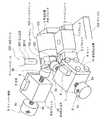
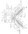
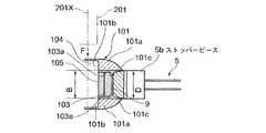
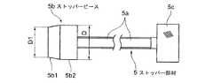
図1は本発明の実施例に係るエンジン用ローラタペットの組立装置の全体構成を示す斜視図、図2は前記ローラタペットの組立装置の一部断面を示す平面図である。図3は前記実施例における図2のA−A線断面図、図4は前記実施例における図2のB−B線断面図、図5は前記実施例におけるストッパー部材の側面図である。
図1〜5において、200は油圧プレス、201は該油圧プレス200の圧入工具、3は該油圧プレス200のテーブル202上に固定されるベースプレート(基台)である。該ベースプレート3上には、ローラタペット100の長手方向に2つのVブロック1,2が並設されている。FIG. 1 is a perspective view showing the overall structure of an assembly apparatus for an engine roller tappet according to an embodiment of the present invention, and FIG. 2 is a plan view showing a partial cross section of the assembly apparatus for the roller tappet. 3 is a cross-sectional view taken along line AA of FIG. 2 in the embodiment, FIG. 4 is a cross-sectional view taken along line BB of FIG. 2 in the embodiment, and FIG. 5 is a side view of the stopper member in the embodiment.
1 to 5, 200 is a hydraulic press, 201 is a press-fitting tool of the
前記2つのVブロック1,2は、図3のように、V字状支持面2aをそなえており、一方側のVブロック2には前記ローラタペット100のローラピン104の挿入部が載置され、他方側のVブロック1には前記ローラタペット100のタペット本体101の円筒部が載置されている。即ち前記ローラタペット100は、タペット本体101の長手方向の軸心101Zを前記Vブロック1,2のV字状支持面2aと平行にして該V字状支持面2a上に載置されている。
図3のように、前記油圧プレス200のテーブル202には、前記圧入工具201と同心上にベースプレート3に穿孔された位置決めピン穴3d及びVブロック2に穿孔された位置決めピン穴3cに位置決めピン11がタペットのローラピン104に当接するように嵌挿されている。これにより、圧入工具201の軸心201Xと、タペット本体101のピン穴101bの中心101Xと、Vブロック2の中心2Xと、位置決めピン11の軸心11Xの全てが同心上に配置されることになる。As shown in FIG. 3, the two
As shown in FIG. 3, the table 202 of the
図2のように、4はタペットの長手方向の位置調整手段である背部位置決めブロックで、前記タペット本体101の背面が当接して、タペット本体101の長手方向の軸心101Z方向にC寸法移動させることにより、タペット本体101の長手方向の軸心101Z方向位置を設定、位置決めするようになっている。 As shown in FIG. 2, reference numeral 4 denotes a back positioning block which is a position adjustment means in the longitudinal direction of the tappet. The back surface of the tappet
このようにタペット本体101の位置決め機構を、油圧プレス200のテーブル202上に該油圧プレス200の圧入工具201と同心に立設されて、ベースプレート3に穿孔された位置決めピン穴3d、およびVブロック2に穿孔された位置決めピン穴3cに嵌合される位置決めピン11と、Vブロック1,2上に載置されたタペット本体101のピン穴101bの中心101Xと圧入工具201の軸心201Xとが全て同心になるようにタペット本体101の位置を調整する背部位置決めブロック4とによって構成したので、位置決めピン11によってベースプレート3およびVブロック2を位置決めし、背部位置決めブロック4によってタペット本体101のピン穴101bの中心がVブロック2の中心に位置されるようにタペット本体101の位置を位置決めすることにより、圧入工具201の軸心201Xとタペット本体101のピン穴101bの中心101Xとを容易に、且つ精度良く一致させることができる。 In this way, the positioning mechanism of the
10,10は変形防止治具で、次のように構成されている。
該変形防止治具10は、前記ベースプレート3上に2個設置され、高さ位置を変化可能な支持ブロック7、該支持ブロック7にねじ結合されたストッパー部材5、前記ベースプレート3上に立設されて前記支持ブロック7を上下移動可能に且つ相対回転不能に嵌合して支持する角形断面の支柱6等からなる。
前記支持ブロック7は、図2のように、前記角形断面の支柱6に嵌合する角形断面の穴をそなえ、該支柱6に沿って相対回転不能で上下移動可能に構成されている。8は前記支柱6を覆うカバーである。
Two of the
As shown in FIG. 2, the
前記ストッパー部材5は、図5に示すように、前記支持ブロック7のねじ穴に螺合されるねじ部5a,手動回転用のつまみ部5c、先端のストッパーピース5bからなる。該ストッパーピース5bは、前記対向内面101c,101c間の幅B(図4参照)と同一あるいは若干大きい外径Dの円柱部5b2、該円柱部5b2の外径Dと先端部の外径D1との間で縮径されたテーパ部5b1とにより形成されている(図5参照)。
そして、前記ストッパー部材5は、図2,4のように、前記つまみ部5cを回転することによって前記ねじ部5aを支持ブロック7のねじ穴に沿って移動させることにより、先端のストッパーピース5bが前記タペット本体101のスカート端部101aのローラ両側面への2つの対向内面101c,101c間の2箇所に挿入可能に構成されている。
前記ストッパー部材5をこのように構成したので、ストッパーピース5bのタペット本体101の対向内面101c,101c間への挿入時に、該対向内面101c,101c間の幅B(図4参照)に公差があっても、該公差に応じてストッパー部材5のテーパ部5b1の押し込み代を調整することができる。もしタペット本体101の長手方向の軸心101ZがVブロック1,2のV字状支持面2a上に平行に載置されなかった場合は、2個のストッパー部材5のテーパ部5b1が対向内面101c間に嵌挿され、スカート部101dの端部が略平行な位置に調整されることにより、タペット本体101の長手方向の軸心101ZがVブロック1,2のV字状支持面2a上に平行に載置され、油圧プレス200の圧入工具201がスカート部101dに接触しないため、変形を防止することができる。As shown in FIG. 5, the
As shown in FIGS. 2 and 4, the
Since the
以上のように、前記変形防止治具10は、前記ベースプレート3上に立設されて前記支持ブロック7を上下移動可能に且つ相対回転不能に嵌合して支持する支柱6をそなえるとともに、前記ストッパー部材5と前記支持ブロック7とをねじ部5aにてねじ結合して該ねじ部5aにより前記タペット本体101の対向内面101c,101c間にテーパ部5b1を挿入あるいは抜き出し可能とし、前記支持ブロック7を前記支柱6との角形嵌合部に沿って上下動せしめることにより、前記ストッパー部材5と前記タペット本体101の対向内面101c,101cとの高さを調整し、前記ストッパー部材5の支持ブロック7へのねじ込み量により前記タペット本体101の対向内面101c,101c間への挿入量を調整するように構成したので、前記ベースプレート3上に立設された角形断面の支柱6に沿ってストッパー部材5の支持ブロック7を自在に上下動できるとともに、該ストッパー部材5の該支持ブロック7へのねじ込み量を変化させることにより、ストッパー部材5のタペット本体101の対向内面101c,101c間への挿入量を容易に調整でき、該ストッパー部材5の先端部位置の前記対向内面101c,101c間への挿入量調整を容易に且つ高精度で行なうことができる。 As described above, the
また、前記2個の変形防止治具10は、図2のように、前記ストッパー部材5の軸心5Zを前記タペット本体101のピン穴101bの中心101Xに対する開き角αが略直角(90°)になるように設置されている。
前記2個の変形防止治具10をこのように構成したので、図2のように該2個の変形防止治具10のストッパー部材5,5を軸心の開き角αが略直角(90°)になるように配置することにより、該ストッパー部材5をスカート端部101aのローラ103の両側面103a,103aへそれぞれ対向する2つの対向内面101c,101c間に挿入する際に、該ストッパー部材5,5の先端のストッパーピース5b部がローラ103の外周に接触することなく且つ前記対向内面101c,101cとストッパー部材5との接触面積を最も大きくとることができる。
さらに、ストッパー部材5のテーパ部5b1が対向内面101c、101c間に嵌挿されることにより、スカート部101dの端部が略平行な位置に調整されることにより、油圧プレス200の圧入工具201がスカート部101dに接触せずに済み、変形を防止できる。Further, as shown in FIG. 2, the two
Since the two
Further, the end portion of the
前記のように構成されたローラタペットの組立装置を用いて前記ローラタペット100を組立てるにあたっては、油圧プレス200のテーブル202上に圧入工具201と同心に立設された位置決めピン11に、ベースプレート3に穿孔された位置決めピン穴3dおよびVブロック2に穿孔された位置決めピン穴3c、を嵌合してベースプレート3およびVブロック2を油圧プレス200のテーブル202上に載置して固定する。Vブロック2は、Vブロック2のV字形状部の中心2Xが、位置決めピン11の軸心11Xと一致するようにベースプレート3上に固定されるため、ベースプレート3およびVブロック2をテーブル202上に載置して固定することによって、Vブロック2のV字形状部の中心と圧入工具201と同心に配置されることとなる。
タペット本体101のローラ収納空間100aに軸受105を介してローラ103を支持した状態で挿入し、さらにローラピン104を前記スカート部101dのピン穴101bに挿入し、ローラタペット100を仮組立状態とし、Vブロック1,2の支持面2aに載置する。When assembling the
Insert the
次いで、あるいは前記動作と同時に、前記タペット本体101の背面が当接する背部位置決めブロック4のタペットの長手方向の軸心101Z方向にC寸法を調整することにより、タペット本体101のピン穴101bの中心101X方向位置が前記圧入工具201と同位置に決まる。
以上の位置決め操作により、タペット本体101は、前記Vブロック1及びVブロック2上に、前記圧入工具201と同心に位置決めされ、前記Vブロック1及びVブロック2上に固定され、前記圧入工具201によって前記ピン穴101b内にローラピン104を圧入可能となる。Next, or simultaneously with the above operation, the
By the above positioning operation, the tappet
以上の操作によって、タペット本体101のピン穴101bの中心101Xを圧入工具201の軸心201Xと同心に位置決めした後、前記タペット本体101のスカート端部101aに形成され前記ローラ103の両側面に対向する前記2つの対向内面101c,101c間に、前記変形防止治具10のストッパー部材5先端のストッパーピース5b部を手動回転用のつまみ部5cを回転することで挿入して、該ストッパーピース5bのテーパ部5b1を前記2つの対向内面101c,101c間に当接させた状態で、前記油圧プレス200の圧入工具201により前記ローラピン104を押圧して前記タペット本体101のピン穴101bに圧入する。
このとき、前記2つの対向内面101c,101c間に前記ストッパーピース5bのテーパ部5b1を挿入しているので、前記圧入工具201によるローラピン104の圧入時に剛性の小さいスカート端部101aが変形して、ローラ103の側面103aと前記対向内面101c,101cとが接触するのを防止できる。Through the above operation, the
At this time, since the tapered portion 5b1 of the
さらに、ストッパー部材5先端のストッパーピース5b部を、手動回転用のつまみ部5cを回転することで対向内面101c,101c間にねじ送りして挿入されるので、タペット本体101の背面を背部位置決めブロック4に押し付ける作用も行うため、タペット本体101の軸心101Z方向におけるピン穴101bの中心101Xの位置が圧入工具201の軸心201Xと同位置に保持され、圧入工具201によるローラピン104の押圧を確実に行なうことができる。
さらに、タペット本体101の軸心101Z方向位置が保持されるばかりでなく、ストッパーピース5bが対向内面101c,101c間に挿入されることで、タペット本体101の軸心101Z回りの回転に対しても位置決めされ保持されるので、一層、圧入工具201によるローラピン104の押圧を確実に行なうことができる。Further, the
Further, not only is the position of the
かかる実施例によれば、油圧プレス200のテーブル202上に圧入工具201の軸心201Xと同心に位置決めピン11を立設し、該位置決めピン11を用いてタペット本体101が載置されるVブロック2、およびVブロック2が固定されるベースプレート3をテーブル202上に位置決めして固定し、タペット本体101のピン穴101bの中心101Xと圧入工具201の軸心201Xとが同心になるようにタペット本体101の位置を調整することによりVブロック1,2上での位置決めを行ない、且つ変形防止治具10のストッパー部材5をタペット本体101のスカート端部101aの2つの対向内面101c,101c間に挿入して該対向内面101c,101cに当接させ、前記油圧プレス200の圧入工具201によりローラピン104をタペット本体101のピン穴101bに圧入する、という油圧プレス200のテーブル202上に載置されるベースプレート3及びVブロック1,2上での一つの工程でローラタペット100を組立てることができる。 According to this embodiment, the
これにより、従来技術のようなベースプレート及びVブロック上での圧入工具によるローラピン104のタペット本体のピン穴101bへの圧入工程(本組付け工程)の前における、油圧プレスの機外でのローラタペット100のスカート端部101aの2つの対向内面101c間に圧入時の変形を防止するための治具を挿入した仮組立品の仮組立てという外段取り工程が不要となり、ローラピン104のタペット本体101への組付け時のスカート端部101aの変形を防止しつつ、従来技術に比べてローラタペット100の組立工数を大幅に低減できる。 Accordingly, the roller tappet outside the press of the hydraulic press before the press-fitting step (main assembly step) of the
また、ベースプレート3上に設置した変形防止治具10を用いてタペット本体101の位置決めと、該変形防止治具10によるスカート端部101aの変形を防止しつつ、圧入工具201によるローラピン104のタペット本体のピン穴101bへの圧入作業を、ワーク及び作業治具及び工具を取外すことなく連続して実施できるので、ローラピン104のタペット本体のピン穴101bへの圧入作業を高精度でかつ迅速に行なうことができ、ローラタペット100の組立作業効率が向上する。 Further, the
本発明によれば、ローラタペットを組立てるに際し、ローラピンをタペット本体に組付けるための外段取り工程を不要として、油圧プレス機械上における一つの工程で且つローラピン組付け時のスカート端部の変形を防止しつつローラタペットの組立を可能としたローラタペットの組立装置及び組立方法を提供できる。 According to the present invention, when assembling the roller tappet, the outer setup process for assembling the roller pin to the tappet body is not required, and deformation of the skirt end is prevented in one process on the hydraulic press machine and when the roller pin is assembled. In addition, it is possible to provide a roller tappet assembling apparatus and a method for assembling a roller tappet.
1、2 Vブロック
2X Vブロック2の中心
2a V字状支持面
3 ベースプレート(基台)
4 背部位置決めブロック
5 ストッパー部材
5a ねじ部
5b ストッパーピース
5b1 テーパ部
5Z ストッパー部材の軸心
6 支柱
7 支持ブロック
10 変形防止治具
11 位置決めピン
11X 位置決めピンの軸心
100 ローラタペット
101 タペット本体
101a スカート端部
101b ピン穴
101c 対向内面
101d スカート部
101X ピン穴の中心
101Z タペット本体の軸心
103 ローラ
104 ローラピン
104X ローラピンの軸心
105 軸受
200 油圧プレス
201 圧入工具
201X 圧入工具の軸心1, 2
4
Claims (6)
Translated fromJapanesePriority Applications (1)
| Application Number | Priority Date | Filing Date | Title |
|---|---|---|---|
| JP2006213936AJP2008036767A (en) | 2006-08-04 | 2006-08-04 | Assembling device of roller tappet and assembling method thereof |
Applications Claiming Priority (1)
| Application Number | Priority Date | Filing Date | Title |
|---|---|---|---|
| JP2006213936AJP2008036767A (en) | 2006-08-04 | 2006-08-04 | Assembling device of roller tappet and assembling method thereof |
Publications (1)
| Publication Number | Publication Date |
|---|---|
| JP2008036767Atrue JP2008036767A (en) | 2008-02-21 |
Family
ID=39172369
Family Applications (1)
| Application Number | Title | Priority Date | Filing Date |
|---|---|---|---|
| JP2006213936AWithdrawnJP2008036767A (en) | 2006-08-04 | 2006-08-04 | Assembling device of roller tappet and assembling method thereof |
Country Status (1)
| Country | Link |
|---|---|
| JP (1) | JP2008036767A (en) |
Cited By (7)
| Publication number | Priority date | Publication date | Assignee | Title |
|---|---|---|---|---|
| CN104526333A (en)* | 2014-12-29 | 2015-04-22 | 贵州雅光电子科技股份有限公司 | Rectifier bridge bolt compression method and bolt compression die |
| CN105127716A (en)* | 2015-08-26 | 2015-12-09 | 金湖县常盛动力机械配件有限公司 | Device for rapidly assembling liquid nitrogen frozen roller pin |
| CN105666092A (en)* | 2015-11-20 | 2016-06-15 | 宁波吉利罗佑发动机零部件有限公司 | Press-fitting device for a stepped type needle roller bearing without inner ring |
| CN106378608A (en)* | 2016-12-08 | 2017-02-08 | 芜湖全程智能科技有限公司 | Assembling method of ABS electromagnetic valve plane filter net and valve body assembly |
| CN106425406A (en)* | 2016-12-08 | 2017-02-22 | 芜湖全程智能科技有限公司 | Device for assembling ABS electromagnetic valve flat screen |
| CN108581463A (en)* | 2018-03-13 | 2018-09-28 | 广东利元亨智能装备有限公司 | A kind of hydraulic tappet automatic assembly equipment |
| CN112077594A (en)* | 2020-09-30 | 2020-12-15 | 中船动力有限公司 | Diesel engine tappet thrust block installation device |
- 2006
- 2006-08-04JPJP2006213936Apatent/JP2008036767A/ennot_activeWithdrawn
Cited By (9)
| Publication number | Priority date | Publication date | Assignee | Title |
|---|---|---|---|---|
| CN104526333A (en)* | 2014-12-29 | 2015-04-22 | 贵州雅光电子科技股份有限公司 | Rectifier bridge bolt compression method and bolt compression die |
| CN105127716A (en)* | 2015-08-26 | 2015-12-09 | 金湖县常盛动力机械配件有限公司 | Device for rapidly assembling liquid nitrogen frozen roller pin |
| CN105666092A (en)* | 2015-11-20 | 2016-06-15 | 宁波吉利罗佑发动机零部件有限公司 | Press-fitting device for a stepped type needle roller bearing without inner ring |
| CN106378608A (en)* | 2016-12-08 | 2017-02-08 | 芜湖全程智能科技有限公司 | Assembling method of ABS electromagnetic valve plane filter net and valve body assembly |
| CN106425406A (en)* | 2016-12-08 | 2017-02-22 | 芜湖全程智能科技有限公司 | Device for assembling ABS electromagnetic valve flat screen |
| CN106378608B (en)* | 2016-12-08 | 2018-07-03 | 芜湖全程智能科技有限公司 | ABS solenoid valves flat screen and the assembly method of valve body assembly |
| CN106425406B (en)* | 2016-12-08 | 2018-08-24 | 芜湖全程智能科技有限公司 | Equipment for the assembly of ABS solenoid valve flat screens |
| CN108581463A (en)* | 2018-03-13 | 2018-09-28 | 广东利元亨智能装备有限公司 | A kind of hydraulic tappet automatic assembly equipment |
| CN112077594A (en)* | 2020-09-30 | 2020-12-15 | 中船动力有限公司 | Diesel engine tappet thrust block installation device |
Similar Documents
| Publication | Publication Date | Title |
|---|---|---|
| JP2008036767A (en) | Assembling device of roller tappet and assembling method thereof | |
| JP6224282B1 (en) | Bearing press-fitting device and bearing press-fitting method | |
| US8359741B2 (en) | Method of machining bearing caps and holding fixture | |
| JP6674805B2 (en) | Machine vise with centering adjustment function | |
| US7771144B1 (en) | Universal jig/work holding fixture and method of use | |
| US10989140B2 (en) | Shaft assembly | |
| KR20080040226A (en) | Work piece clamping device for machine center | |
| JP4904074B2 (en) | Drawing device | |
| EP4289547A1 (en) | Tool and method for machining injector housing and inner bottom | |
| DE10084486T5 (en) | Alignment of the crankshaft bearings of a scroll compressor | |
| TWI400393B (en) | Locating pins | |
| JP2845756B2 (en) | Swing jig bearing clamp device | |
| KR101983341B1 (en) | Processing method thereof for planetary gear carrier of auto transmission and processing device | |
| JPH09276957A (en) | Die holder mounting structure | |
| US7220085B2 (en) | Universal jig/work holding fixture and method of use | |
| JP2018112128A (en) | Centering jig and centering method of rotor blade variable axial flow fan | |
| JP2000081104A (en) | Cam positioning structure of indexing drive | |
| JP6825812B2 (en) | Alignment stage and processing equipment equipped with it | |
| JP2019018258A (en) | Hub bearing press-fitting tool | |
| KR100420558B1 (en) | Yoke Clearance and Position Control Device for Universal Joint | |
| JP6840987B2 (en) | Hub unit manufacturing equipment | |
| JPH091260A (en) | Quick die change device | |
| JP2002079402A (en) | Beveling machine for piping | |
| CN101737475B (en) | Insertion clamp apparatus, straightening apparatus and straightening method | |
| KR200211430Y1 (en) | Spindle body close adherence device of vertical lathe |
Legal Events
| Date | Code | Title | Description |
|---|---|---|---|
| A711 | Notification of change in applicant | Free format text:JAPANESE INTERMEDIATE CODE: A712 Effective date:20090831 | |
| A300 | Withdrawal of application because of no request for examination | Free format text:JAPANESE INTERMEDIATE CODE: A300 Effective date:20091006 | |
| A072 | Dismissal of procedure | Free format text:JAPANESE INTERMEDIATE CODE: A072 Effective date:20100126 |