JP2008036418A - Restoration by prosthesis of intra-corporeal pathway - Google Patents
Restoration by prosthesis of intra-corporeal pathwayDownload PDFInfo
- Publication number
- JP2008036418A JP2008036418AJP2007186160AJP2007186160AJP2008036418AJP 2008036418 AJP2008036418 AJP 2008036418AJP 2007186160 AJP2007186160 AJP 2007186160AJP 2007186160 AJP2007186160 AJP 2007186160AJP 2008036418 AJP2008036418 AJP 2008036418A
- Authority
- JP
- Japan
- Prior art keywords
- prosthesis
- ring
- graft
- diameter
- pair
- Prior art date
- Legal status (The legal status is an assumption and is not a legal conclusion. Google has not performed a legal analysis and makes no representation as to the accuracy of the status listed.)
- Granted
Links
- 230000037361pathwayEffects0.000titleabstract7
- 210000004204blood vesselAnatomy0.000claimsabstractdescription36
- 239000007943implantSubstances0.000claimsabstractdescription16
- 210000000702aorta abdominalAnatomy0.000claimsabstractdescription6
- 238000000034methodMethods0.000claimsdescription32
- 238000003780insertionMethods0.000claimsdescription10
- 230000037431insertionEffects0.000claimsdescription10
- 210000000709aortaAnatomy0.000claimsdescription6
- 210000003709heart valveAnatomy0.000claimsdescription4
- 210000003090iliac arteryAnatomy0.000claimsdescription4
- 229910001000nickel titaniumInorganic materials0.000claimsdescription4
- 210000002254renal arteryAnatomy0.000claimsdescription4
- 229910052751metalInorganic materials0.000claimsdescription3
- 239000002184metalSubstances0.000claimsdescription3
- 230000008439repair processEffects0.000claimsdescription2
- 239000002759woven fabricSubstances0.000claimsdescription2
- 239000004753textileSubstances0.000claims2
- 238000004804windingMethods0.000claims2
- 206010002329AneurysmDiseases0.000abstractdescription5
- 210000003739neckAnatomy0.000description16
- 230000000903blocking effectEffects0.000description14
- 239000000463materialSubstances0.000description8
- 210000001367arteryAnatomy0.000description7
- 230000017531blood circulationEffects0.000description7
- 238000005452bendingMethods0.000description6
- 230000002792vascularEffects0.000description6
- 230000006835compressionEffects0.000description4
- 238000007906compressionMethods0.000description4
- 230000004048modificationEffects0.000description4
- 238000012986modificationMethods0.000description4
- 238000013461designMethods0.000description3
- 230000007246mechanismEffects0.000description3
- 230000008859changeEffects0.000description2
- 239000004744fabricSubstances0.000description2
- HLXZNVUGXRDIFK-UHFFFAOYSA-Nnickel titaniumChemical compound[Ti].[Ti].[Ti].[Ti].[Ti].[Ti].[Ti].[Ti].[Ti].[Ti].[Ti].[Ni].[Ni].[Ni].[Ni].[Ni].[Ni].[Ni].[Ni].[Ni].[Ni].[Ni].[Ni].[Ni].[Ni]HLXZNVUGXRDIFK-UHFFFAOYSA-N0.000description2
- 230000035479physiological effects, processes and functionsEffects0.000description2
- 239000004033plasticSubstances0.000description2
- BASFCYQUMIYNBI-UHFFFAOYSA-NplatinumChemical compound[Pt]BASFCYQUMIYNBI-UHFFFAOYSA-N0.000description2
- 230000008569processEffects0.000description2
- 238000001356surgical procedureMethods0.000description2
- 206010003210ArteriosclerosisDiseases0.000description1
- 229920004934Dacron®Polymers0.000description1
- 239000004809TeflonSubstances0.000description1
- 229920006362Teflon®Polymers0.000description1
- 230000009471actionEffects0.000description1
- 239000000654additiveSubstances0.000description1
- 230000000996additive effectEffects0.000description1
- 238000004026adhesive bondingMethods0.000description1
- 230000002411adverseEffects0.000description1
- 238000013459approachMethods0.000description1
- 208000011775arteriosclerosis diseaseDiseases0.000description1
- 239000008280bloodSubstances0.000description1
- 210000004369bloodAnatomy0.000description1
- 230000036772blood pressureEffects0.000description1
- 238000009954braidingMethods0.000description1
- 238000004033diameter controlMethods0.000description1
- 230000000694effectsEffects0.000description1
- 239000013013elastic materialSubstances0.000description1
- PCHJSUWPFVWCPO-UHFFFAOYSA-NgoldChemical compound[Au]PCHJSUWPFVWCPO-UHFFFAOYSA-N0.000description1
- 229910052737goldInorganic materials0.000description1
- 239000010931goldSubstances0.000description1
- 210000004013groinAnatomy0.000description1
- 238000002513implantationMethods0.000description1
- 208000014674injuryDiseases0.000description1
- 229910052741iridiumInorganic materials0.000description1
- GKOZUEZYRPOHIO-UHFFFAOYSA-Niridium atomChemical compound[Ir]GKOZUEZYRPOHIO-UHFFFAOYSA-N0.000description1
- 230000003902lesionEffects0.000description1
- 230000014759maintenance of locationEffects0.000description1
- 239000003550markerSubstances0.000description1
- 229910000734martensiteInorganic materials0.000description1
- 239000012528membraneSubstances0.000description1
- 229910052697platinumInorganic materials0.000description1
- 239000005020polyethylene terephthalateSubstances0.000description1
- 238000012887quadratic functionMethods0.000description1
- 230000005855radiationEffects0.000description1
- 230000003014reinforcing effectEffects0.000description1
- 230000008733traumaEffects0.000description1
- 238000011144upstream manufacturingMethods0.000description1
- 230000024883vasodilationEffects0.000description1
Images


Classifications
- A—HUMAN NECESSITIES
- A61—MEDICAL OR VETERINARY SCIENCE; HYGIENE
- A61F—FILTERS IMPLANTABLE INTO BLOOD VESSELS; PROSTHESES; DEVICES PROVIDING PATENCY TO, OR PREVENTING COLLAPSING OF, TUBULAR STRUCTURES OF THE BODY, e.g. STENTS; ORTHOPAEDIC, NURSING OR CONTRACEPTIVE DEVICES; FOMENTATION; TREATMENT OR PROTECTION OF EYES OR EARS; BANDAGES, DRESSINGS OR ABSORBENT PADS; FIRST-AID KITS
- A61F2/00—Filters implantable into blood vessels; Prostheses, i.e. artificial substitutes or replacements for parts of the body; Appliances for connecting them with the body; Devices providing patency to, or preventing collapsing of, tubular structures of the body, e.g. stents
- A61F2/02—Prostheses implantable into the body
- A61F2/04—Hollow or tubular parts of organs, e.g. bladders, tracheae, bronchi or bile ducts
- A61F2/06—Blood vessels
- A61F2/07—Stent-grafts
- A—HUMAN NECESSITIES
- A61—MEDICAL OR VETERINARY SCIENCE; HYGIENE
- A61F—FILTERS IMPLANTABLE INTO BLOOD VESSELS; PROSTHESES; DEVICES PROVIDING PATENCY TO, OR PREVENTING COLLAPSING OF, TUBULAR STRUCTURES OF THE BODY, e.g. STENTS; ORTHOPAEDIC, NURSING OR CONTRACEPTIVE DEVICES; FOMENTATION; TREATMENT OR PROTECTION OF EYES OR EARS; BANDAGES, DRESSINGS OR ABSORBENT PADS; FIRST-AID KITS
- A61F2/00—Filters implantable into blood vessels; Prostheses, i.e. artificial substitutes or replacements for parts of the body; Appliances for connecting them with the body; Devices providing patency to, or preventing collapsing of, tubular structures of the body, e.g. stents
- A61F2/95—Instruments specially adapted for placement or removal of stents or stent-grafts
- A—HUMAN NECESSITIES
- A61—MEDICAL OR VETERINARY SCIENCE; HYGIENE
- A61F—FILTERS IMPLANTABLE INTO BLOOD VESSELS; PROSTHESES; DEVICES PROVIDING PATENCY TO, OR PREVENTING COLLAPSING OF, TUBULAR STRUCTURES OF THE BODY, e.g. STENTS; ORTHOPAEDIC, NURSING OR CONTRACEPTIVE DEVICES; FOMENTATION; TREATMENT OR PROTECTION OF EYES OR EARS; BANDAGES, DRESSINGS OR ABSORBENT PADS; FIRST-AID KITS
- A61F2/00—Filters implantable into blood vessels; Prostheses, i.e. artificial substitutes or replacements for parts of the body; Appliances for connecting them with the body; Devices providing patency to, or preventing collapsing of, tubular structures of the body, e.g. stents
- A61F2/02—Prostheses implantable into the body
- A61F2/24—Heart valves ; Vascular valves, e.g. venous valves; Heart implants, e.g. passive devices for improving the function of the native valve or the heart muscle; Transmyocardial revascularisation [TMR] devices; Valves implantable in the body
- A61F2/2412—Heart valves ; Vascular valves, e.g. venous valves; Heart implants, e.g. passive devices for improving the function of the native valve or the heart muscle; Transmyocardial revascularisation [TMR] devices; Valves implantable in the body with soft flexible valve members, e.g. tissue valves shaped like natural valves
- A—HUMAN NECESSITIES
- A61—MEDICAL OR VETERINARY SCIENCE; HYGIENE
- A61F—FILTERS IMPLANTABLE INTO BLOOD VESSELS; PROSTHESES; DEVICES PROVIDING PATENCY TO, OR PREVENTING COLLAPSING OF, TUBULAR STRUCTURES OF THE BODY, e.g. STENTS; ORTHOPAEDIC, NURSING OR CONTRACEPTIVE DEVICES; FOMENTATION; TREATMENT OR PROTECTION OF EYES OR EARS; BANDAGES, DRESSINGS OR ABSORBENT PADS; FIRST-AID KITS
- A61F2/00—Filters implantable into blood vessels; Prostheses, i.e. artificial substitutes or replacements for parts of the body; Appliances for connecting them with the body; Devices providing patency to, or preventing collapsing of, tubular structures of the body, e.g. stents
- A61F2/02—Prostheses implantable into the body
- A61F2/24—Heart valves ; Vascular valves, e.g. venous valves; Heart implants, e.g. passive devices for improving the function of the native valve or the heart muscle; Transmyocardial revascularisation [TMR] devices; Valves implantable in the body
- A61F2/2427—Devices for manipulating or deploying heart valves during implantation
- A61F2/2439—Expansion controlled by filaments
- A—HUMAN NECESSITIES
- A61—MEDICAL OR VETERINARY SCIENCE; HYGIENE
- A61F—FILTERS IMPLANTABLE INTO BLOOD VESSELS; PROSTHESES; DEVICES PROVIDING PATENCY TO, OR PREVENTING COLLAPSING OF, TUBULAR STRUCTURES OF THE BODY, e.g. STENTS; ORTHOPAEDIC, NURSING OR CONTRACEPTIVE DEVICES; FOMENTATION; TREATMENT OR PROTECTION OF EYES OR EARS; BANDAGES, DRESSINGS OR ABSORBENT PADS; FIRST-AID KITS
- A61F2/00—Filters implantable into blood vessels; Prostheses, i.e. artificial substitutes or replacements for parts of the body; Appliances for connecting them with the body; Devices providing patency to, or preventing collapsing of, tubular structures of the body, e.g. stents
- A61F2/82—Devices providing patency to, or preventing collapsing of, tubular structures of the body, e.g. stents
- A61F2/86—Stents in a form characterised by the wire-like elements; Stents in the form characterised by a net-like or mesh-like structure
- A61F2/89—Stents in a form characterised by the wire-like elements; Stents in the form characterised by a net-like or mesh-like structure the wire-like elements comprising two or more adjacent rings flexibly connected by separate members
- A—HUMAN NECESSITIES
- A61—MEDICAL OR VETERINARY SCIENCE; HYGIENE
- A61F—FILTERS IMPLANTABLE INTO BLOOD VESSELS; PROSTHESES; DEVICES PROVIDING PATENCY TO, OR PREVENTING COLLAPSING OF, TUBULAR STRUCTURES OF THE BODY, e.g. STENTS; ORTHOPAEDIC, NURSING OR CONTRACEPTIVE DEVICES; FOMENTATION; TREATMENT OR PROTECTION OF EYES OR EARS; BANDAGES, DRESSINGS OR ABSORBENT PADS; FIRST-AID KITS
- A61F2/00—Filters implantable into blood vessels; Prostheses, i.e. artificial substitutes or replacements for parts of the body; Appliances for connecting them with the body; Devices providing patency to, or preventing collapsing of, tubular structures of the body, e.g. stents
- A61F2/95—Instruments specially adapted for placement or removal of stents or stent-grafts
- A61F2/954—Instruments specially adapted for placement or removal of stents or stent-grafts for placing stents or stent-grafts in a bifurcation
- A—HUMAN NECESSITIES
- A61—MEDICAL OR VETERINARY SCIENCE; HYGIENE
- A61F—FILTERS IMPLANTABLE INTO BLOOD VESSELS; PROSTHESES; DEVICES PROVIDING PATENCY TO, OR PREVENTING COLLAPSING OF, TUBULAR STRUCTURES OF THE BODY, e.g. STENTS; ORTHOPAEDIC, NURSING OR CONTRACEPTIVE DEVICES; FOMENTATION; TREATMENT OR PROTECTION OF EYES OR EARS; BANDAGES, DRESSINGS OR ABSORBENT PADS; FIRST-AID KITS
- A61F2/00—Filters implantable into blood vessels; Prostheses, i.e. artificial substitutes or replacements for parts of the body; Appliances for connecting them with the body; Devices providing patency to, or preventing collapsing of, tubular structures of the body, e.g. stents
- A61F2/02—Prostheses implantable into the body
- A61F2/04—Hollow or tubular parts of organs, e.g. bladders, tracheae, bronchi or bile ducts
- A61F2/06—Blood vessels
- A61F2002/065—Y-shaped blood vessels
- A61F2002/067—Y-shaped blood vessels modular
- A—HUMAN NECESSITIES
- A61—MEDICAL OR VETERINARY SCIENCE; HYGIENE
- A61F—FILTERS IMPLANTABLE INTO BLOOD VESSELS; PROSTHESES; DEVICES PROVIDING PATENCY TO, OR PREVENTING COLLAPSING OF, TUBULAR STRUCTURES OF THE BODY, e.g. STENTS; ORTHOPAEDIC, NURSING OR CONTRACEPTIVE DEVICES; FOMENTATION; TREATMENT OR PROTECTION OF EYES OR EARS; BANDAGES, DRESSINGS OR ABSORBENT PADS; FIRST-AID KITS
- A61F2/00—Filters implantable into blood vessels; Prostheses, i.e. artificial substitutes or replacements for parts of the body; Appliances for connecting them with the body; Devices providing patency to, or preventing collapsing of, tubular structures of the body, e.g. stents
- A61F2/02—Prostheses implantable into the body
- A61F2/04—Hollow or tubular parts of organs, e.g. bladders, tracheae, bronchi or bile ducts
- A61F2/06—Blood vessels
- A61F2/07—Stent-grafts
- A61F2002/075—Stent-grafts the stent being loosely attached to the graft material, e.g. by stitching
- A—HUMAN NECESSITIES
- A61—MEDICAL OR VETERINARY SCIENCE; HYGIENE
- A61F—FILTERS IMPLANTABLE INTO BLOOD VESSELS; PROSTHESES; DEVICES PROVIDING PATENCY TO, OR PREVENTING COLLAPSING OF, TUBULAR STRUCTURES OF THE BODY, e.g. STENTS; ORTHOPAEDIC, NURSING OR CONTRACEPTIVE DEVICES; FOMENTATION; TREATMENT OR PROTECTION OF EYES OR EARS; BANDAGES, DRESSINGS OR ABSORBENT PADS; FIRST-AID KITS
- A61F2/00—Filters implantable into blood vessels; Prostheses, i.e. artificial substitutes or replacements for parts of the body; Appliances for connecting them with the body; Devices providing patency to, or preventing collapsing of, tubular structures of the body, e.g. stents
- A61F2/02—Prostheses implantable into the body
- A61F2/30—Joints
- A61F2002/30001—Additional features of subject-matter classified in A61F2/28, A61F2/30 and subgroups thereof
- A61F2002/30316—The prosthesis having different structural features at different locations within the same prosthesis; Connections between prosthetic parts; Special structural features of bone or joint prostheses not otherwise provided for
- A61F2002/30317—The prosthesis having different structural features at different locations within the same prosthesis
- A61F2002/30327—The prosthesis having different structural features at different locations within the same prosthesis differing in diameter
- A—HUMAN NECESSITIES
- A61—MEDICAL OR VETERINARY SCIENCE; HYGIENE
- A61F—FILTERS IMPLANTABLE INTO BLOOD VESSELS; PROSTHESES; DEVICES PROVIDING PATENCY TO, OR PREVENTING COLLAPSING OF, TUBULAR STRUCTURES OF THE BODY, e.g. STENTS; ORTHOPAEDIC, NURSING OR CONTRACEPTIVE DEVICES; FOMENTATION; TREATMENT OR PROTECTION OF EYES OR EARS; BANDAGES, DRESSINGS OR ABSORBENT PADS; FIRST-AID KITS
- A61F2/00—Filters implantable into blood vessels; Prostheses, i.e. artificial substitutes or replacements for parts of the body; Appliances for connecting them with the body; Devices providing patency to, or preventing collapsing of, tubular structures of the body, e.g. stents
- A61F2/02—Prostheses implantable into the body
- A61F2/30—Joints
- A61F2002/30001—Additional features of subject-matter classified in A61F2/28, A61F2/30 and subgroups thereof
- A61F2002/30316—The prosthesis having different structural features at different locations within the same prosthesis; Connections between prosthetic parts; Special structural features of bone or joint prostheses not otherwise provided for
- A61F2002/30329—Connections or couplings between prosthetic parts, e.g. between modular parts; Connecting elements
- A61F2002/30476—Connections or couplings between prosthetic parts, e.g. between modular parts; Connecting elements locked by an additional locking mechanism
- A61F2002/30505—Connections or couplings between prosthetic parts, e.g. between modular parts; Connecting elements locked by an additional locking mechanism spring biased
- A—HUMAN NECESSITIES
- A61—MEDICAL OR VETERINARY SCIENCE; HYGIENE
- A61F—FILTERS IMPLANTABLE INTO BLOOD VESSELS; PROSTHESES; DEVICES PROVIDING PATENCY TO, OR PREVENTING COLLAPSING OF, TUBULAR STRUCTURES OF THE BODY, e.g. STENTS; ORTHOPAEDIC, NURSING OR CONTRACEPTIVE DEVICES; FOMENTATION; TREATMENT OR PROTECTION OF EYES OR EARS; BANDAGES, DRESSINGS OR ABSORBENT PADS; FIRST-AID KITS
- A61F2/00—Filters implantable into blood vessels; Prostheses, i.e. artificial substitutes or replacements for parts of the body; Appliances for connecting them with the body; Devices providing patency to, or preventing collapsing of, tubular structures of the body, e.g. stents
- A61F2/82—Devices providing patency to, or preventing collapsing of, tubular structures of the body, e.g. stents
- A61F2002/826—Devices providing patency to, or preventing collapsing of, tubular structures of the body, e.g. stents more than one stent being applied sequentially
- A—HUMAN NECESSITIES
- A61—MEDICAL OR VETERINARY SCIENCE; HYGIENE
- A61F—FILTERS IMPLANTABLE INTO BLOOD VESSELS; PROSTHESES; DEVICES PROVIDING PATENCY TO, OR PREVENTING COLLAPSING OF, TUBULAR STRUCTURES OF THE BODY, e.g. STENTS; ORTHOPAEDIC, NURSING OR CONTRACEPTIVE DEVICES; FOMENTATION; TREATMENT OR PROTECTION OF EYES OR EARS; BANDAGES, DRESSINGS OR ABSORBENT PADS; FIRST-AID KITS
- A61F2/00—Filters implantable into blood vessels; Prostheses, i.e. artificial substitutes or replacements for parts of the body; Appliances for connecting them with the body; Devices providing patency to, or preventing collapsing of, tubular structures of the body, e.g. stents
- A61F2/95—Instruments specially adapted for placement or removal of stents or stent-grafts
- A61F2002/9505—Instruments specially adapted for placement or removal of stents or stent-grafts having retaining means other than an outer sleeve, e.g. male-female connector between stent and instrument
- A61F2002/9511—Instruments specially adapted for placement or removal of stents or stent-grafts having retaining means other than an outer sleeve, e.g. male-female connector between stent and instrument the retaining means being filaments or wires
- A—HUMAN NECESSITIES
- A61—MEDICAL OR VETERINARY SCIENCE; HYGIENE
- A61F—FILTERS IMPLANTABLE INTO BLOOD VESSELS; PROSTHESES; DEVICES PROVIDING PATENCY TO, OR PREVENTING COLLAPSING OF, TUBULAR STRUCTURES OF THE BODY, e.g. STENTS; ORTHOPAEDIC, NURSING OR CONTRACEPTIVE DEVICES; FOMENTATION; TREATMENT OR PROTECTION OF EYES OR EARS; BANDAGES, DRESSINGS OR ABSORBENT PADS; FIRST-AID KITS
- A61F2220/00—Fixations or connections for prostheses classified in groups A61F2/00 - A61F2/26 or A61F2/82 or A61F9/00 or A61F11/00 or subgroups thereof
- A61F2220/0025—Connections or couplings between prosthetic parts, e.g. between modular parts; Connecting elements
- A—HUMAN NECESSITIES
- A61—MEDICAL OR VETERINARY SCIENCE; HYGIENE
- A61F—FILTERS IMPLANTABLE INTO BLOOD VESSELS; PROSTHESES; DEVICES PROVIDING PATENCY TO, OR PREVENTING COLLAPSING OF, TUBULAR STRUCTURES OF THE BODY, e.g. STENTS; ORTHOPAEDIC, NURSING OR CONTRACEPTIVE DEVICES; FOMENTATION; TREATMENT OR PROTECTION OF EYES OR EARS; BANDAGES, DRESSINGS OR ABSORBENT PADS; FIRST-AID KITS
- A61F2250/00—Special features of prostheses classified in groups A61F2/00 - A61F2/26 or A61F2/82 or A61F9/00 or A61F11/00 or subgroups thereof
- A61F2250/0014—Special features of prostheses classified in groups A61F2/00 - A61F2/26 or A61F2/82 or A61F9/00 or A61F11/00 or subgroups thereof having different values of a given property or geometrical feature, e.g. mechanical property or material property, at different locations within the same prosthesis
- A61F2250/0039—Special features of prostheses classified in groups A61F2/00 - A61F2/26 or A61F2/82 or A61F9/00 or A61F11/00 or subgroups thereof having different values of a given property or geometrical feature, e.g. mechanical property or material property, at different locations within the same prosthesis differing in diameter
Landscapes
- Health & Medical Sciences (AREA)
- Engineering & Computer Science (AREA)
- Biomedical Technology (AREA)
- Cardiology (AREA)
- Oral & Maxillofacial Surgery (AREA)
- Transplantation (AREA)
- Heart & Thoracic Surgery (AREA)
- Vascular Medicine (AREA)
- Life Sciences & Earth Sciences (AREA)
- Animal Behavior & Ethology (AREA)
- General Health & Medical Sciences (AREA)
- Public Health (AREA)
- Veterinary Medicine (AREA)
- Gastroenterology & Hepatology (AREA)
- Pulmonology (AREA)
- Prostheses (AREA)
- Media Introduction/Drainage Providing Device (AREA)
- Surgical Instruments (AREA)
Abstract
Description
Translated fromJapanese 発明の背景
本発明は、体内の径路内に留置する装置に関し、特に、動脈瘤として知られる動脈拡張症の治療に使用する血管用ステントに関する。BACKGROUND OF THE INVENTION The present invention relates to a device for placement in a body passageway, and in particular to a vascular stent for use in the treatment of arterial dilatation known as an aneurysm.
動脈硬化が起きると、血管が部分的に弱まり、極度に拡張する場合がある。このような拡張した血管は、拡張部分または弱まって広がった部分に血管用管形補綴を使って補強することにより治療することができる。このように、血管の罹病部分は、血管内の圧力から効果的に隔離することができる。 When arteriosclerosis occurs, blood vessels may partially weaken and become extremely dilated. Such dilated blood vessels can be treated by reinforcing the dilated portion or weakened and dilated portion with a vascular tubular prosthesis. In this way, the affected part of the blood vessel can be effectively isolated from the pressure in the blood vessel.
血管用管形補綴は、血管を外科的手術によって開き、補綴を定位置に縫合することによって、罹病部分に挿入することができる。しかし、補綴は、カテーテルシステムを使って鼠径部に隣接する股動脈のような、遠隔の開口部から挿入するのが好ましい。これは、身体の主要な腔を切開する必要がないため、外科的処置によって起こりうる合併症の可能性を減少させることができるからである。 A vascular tubular prosthesis can be inserted into the affected area by opening the blood vessel surgically and suturing the prosthesis in place. However, the prosthesis is preferably inserted through a remote opening, such as the hip artery adjacent to the groin, using a catheter system. This is because there is no need to incise the main body cavity, thus reducing the potential for complications that can arise from surgical procedures.
一般的に、カテーテルを使って、補綴を折りたたんだ状態、あるいは圧縮した状態で挿入し、定位置についてから補綴を拡張するのが望ましい。その理由の一つは、挿入過程において血液の流れを実質的に遮断するのは避けたようがよいからである。従って、補綴を折りたたむことにより、場合によっては、血液の流れを実質的に遮断することなく、補綴を容易に血管内に位置させることができる。 In general, it is desirable to insert the prosthesis in a folded or compressed state using a catheter and expand the prosthesis from a fixed position. One reason is that it may be desirable to avoid substantially blocking blood flow during the insertion process. Therefore, by folding the prosthesis, in some cases, the prosthesis can be easily positioned within the blood vessel without substantially blocking the blood flow.
一般的には、補綴が修復すべき位置に配置されてから、補綴を拡張する方法として、二つの技術がある。一つの技術では、二つの形状を有する可鍛性の補綴を使用する。一つの形状は、直径が比較的小さく、もう一つの形状は、罹病血管部分のいずれかの側の頚部に接触し、固定する相対的に半径方向に拡張した形状である。この補綴は、可鍛性の金属でできたリングであり、バルーンカテーテルによって拡張し、直径を拡張した状態の補綴を血管の罹病部分に近接する頚部の内側に取り付けることができる。 In general, there are two techniques for expanding a prosthesis after the prosthesis is placed at a position to be repaired. One technique uses a malleable prosthesis having two shapes. One shape is relatively small in diameter and the other shape is a relatively radially expanded shape that contacts and secures the neck on either side of the affected blood vessel portion. The prosthesis is a ring made of malleable metal and can be expanded by a balloon catheter to attach the expanded prosthesis inside the neck close to the diseased portion of the blood vessel.
もう一つの一般的な方法は、斜め方向の弾性に抗して圧縮することができる自己拡張型の補綴を使用する方法である。適切な位置に到達すると、補綴は、復元力で拡張し、血管の壁に接触する。 Another common method is to use a self-expanding prosthesis that can be compressed against diagonal elasticity. Upon reaching the proper position, the prosthesis expands with restoring force and contacts the vessel wall.
罹病組織を効果的に回避するという課題に対して様々な解決策が提案されてきたが、現存の様々な補綴装置の設計には、ある程度の欠点が伴う。例えば、罹病血管部分のいずれかの側にある頚部が比較的短い場合がある。そのため、補綴装置を動脈瘤のいずれかの側にある頚部に適切に係合させるのが難しい。 While various solutions have been proposed to the problem of effectively avoiding diseased tissue, the design of various existing prosthetic devices has some drawbacks. For example, the neck on either side of the affected blood vessel portion may be relatively short. Therefore, it is difficult to properly engage the prosthetic device with the neck on either side of the aneurysm.
さらに、現存の補綴には、補綴挿入中に血液の流れを止めてしまうものもあり、これは、生理的に悪影響を及ぼす可能性がある。また、もう一つの問題は、現存の補綴の多くは、血管の内表面に対する密閉性が適切でないため、血液が補綴を通過して、補綴と弱った血管との間の領域に漏れ出てしまう場合があるという点である。このような漏れが起きた結果、外傷につながる可能性もある。設計によっては、この装置は、円形でない、または不規則な形状の頚部領域には適合できないものもある。 In addition, some existing prostheses stop blood flow during prosthesis insertion, which can have a physiological adverse effect. Another problem is that many of the existing prostheses are not properly sealed to the inner surface of the blood vessel, so that blood passes through the prosthesis and leaks into the area between the prosthesis and the weakened blood vessel. There is a case. Such leaks can result in trauma. Depending on the design, this device may not fit into a non-circular or irregularly shaped cervical region.
周知の補綴におけるさらにもう一つの問題は、病院が、状況や患者の生理に合わせて様々な寸法の補綴を在庫として保有していなければならない場合があるということである。また、設計によっては、補綴を特別な患者個人に合わせてあつらえなければならないものもある。 Yet another problem with known prostheses is that hospitals may have to stock various sizes of prostheses to suit the situation and the patient's physiology. In some designs, the prosthesis must be tailored to a particular individual patient.
さらに、一度拡張してしまった場合には、正確な位置決めを行なうのが困難な場合がある。不正確な位置決めをしてしまうと、解決が難しくなる場合もある。
同様に、現存の補綴の多くは、希望の位置から外れてしまい、弱った血管を保護するという機能を効果的に果たさないといったことが起きる可能性がある。Furthermore, once expanded, accurate positioning may be difficult. Incorrect positioning can be difficult to solve.
Similarly, many existing prostheses may be out of the desired position and fail to effectively perform the function of protecting weakened blood vessels.
これらの、そして他の理由から、罹病血管を修復するという課題と、さらに一般的に言えば、体内の径路の内壁に補綴装置を効果的に固定するという課題に対するよりよい解決策が引き続き必要である。 For these and other reasons, there remains a need for better solutions to the challenge of repairing diseased blood vessels and, more generally, the task of effectively securing a prosthetic device to the inner wall of a body passage. is there.
発明の要約
本発明の一つの特徴は、補綴を体内の径路に留置するための装置は、環状の弾性要素を含むということである。この要素の変形前の直径は、体内の径路の直径よりも大きい。
本発明のもう一つの特徴は、体内の径路に挿入する補綴は、環状の弾性ばね要素と管形移植片を含むということである。移植片は、要素に取り付けることができる。この要素の変形前の直径は、移植片の直径よりも大きい。SUMMARY OF THE INVENTION One feature of the present invention is that a device for placing a prosthesis in a body passage includes an annular elastic element. The diameter of this element before deformation is larger than the diameter of the body path.
Another feature of the present invention is that the prosthesis for insertion into the body passage includes an annular elastic spring element and a tubular graft. The implant can be attached to the element. The diameter of this element before deformation is larger than the diameter of the graft.
本発明のさらにもう一つの特徴は、罹病状態の第1の血管を修復するための血管用補綴が、一方向に延在する第1の対のループと、反対方向に延在する第2の対のループとを有する弾性の環状リングを含むという点である。第1と第2の対のループは、互いに連結してある。管形の移植片は、リングに接合してある。移植片は、第1の血管の全長にわたって延在するように配置し、第1の対のループは、第2の血管が第1の血管と交差する点を少なくとも部分的に超えて延在するように配置してある。第2の対のループのうちの一方は開口部を形成しており、少なくとも部分的に補綴を超えて第1と第2の血管の間を連通させる。 Yet another feature of the present invention is that a vascular prosthesis for repairing a diseased first blood vessel includes a first pair of loops extending in one direction and a second pair extending in the opposite direction. It includes an elastic annular ring having a pair of loops. The first and second pairs of loops are connected to each other. The tubular graft is joined to the ring. The implant is positioned to extend the entire length of the first blood vessel, and the first pair of loops extends at least partially beyond the point where the second blood vessel intersects the first blood vessel. It is arranged as follows. One of the second pair of loops forms an opening that communicates between the first and second blood vessels at least partially beyond the prosthesis.
本発明のさらにもう一つの特徴は、補綴装置を体内の径路に固定する方法に、断面積が変形前のリングの断面積より小さい第1の形状に弾性環状リングを折りたたむ工程を含む点である。リングは、体内の径路の希望の箇所に位置させ、第1の形状より直径が大きく、かつ、変形前のリングの直径よりも小さい第2の形状に弾力的に変形させる。 Yet another feature of the present invention is that a method of securing a prosthetic device to a body passage includes the step of folding an elastic annular ring into a first shape whose cross-sectional area is smaller than the cross-sectional area of the ring before deformation. . The ring is positioned at a desired location in the body path and is elastically deformed into a second shape having a diameter larger than that of the first shape and smaller than the diameter of the ring before deformation.
本発明の、さらにもう一つの特徴は、罹病血管を修復する方法に、環状リングをその直径に沿った軸で折りたたんで、断面の小さい形状にし、この軸から離れる方向に延在する一対のループを形成する工程を含む点である。リングは、その直径に沿った軸を交差する血管に近接させて、ループが、交差する血管を遮断することなく、少なくとも部分的に交差する血管を超えて延在するように配置する。 Yet another feature of the present invention is a method of repairing a diseased blood vessel in which a pair of loops are formed by folding an annular ring around an axis along its diameter to form a small cross-section and extending away from the axis. It is a point including the process of forming. The ring is positioned so that the axis along its diameter is in close proximity to the intersecting vessel and the loop extends at least partially beyond the intersecting vessel without blocking the intersecting vessel.
本発明の、さらにもう一つの特徴は、体内の径路の中に補綴装置を固定する方法に、環状弾性ばねをその直径に沿った軸で折りたたむことによって変形させる工程を含む点である。ばねは、体内の径路の中に位置させる。ばねは、体内の径路に向かって弾力的に拡張する。ばねは、連続的に体内の径路を外側方向に押し出す。 Yet another feature of the present invention is that a method of securing a prosthetic device in a body passage includes deforming the annular elastic spring by folding it about an axis along its diameter. The spring is located in the body path. The spring elastically expands toward the body path. The spring continuously pushes the body path outward.
本発明の、さらにもう一つの特徴は、補綴装置には、心臓弁用補綴が含まれるという点で、これは、弁と連結可能な第1の端部と、第2の端部を有する可撓性の管形スリーブである。変形可能な弾性環状リングを第2の端部に連結し、移植片を上行大動脈の一部の内側表面に接合するように配置する。 Yet another feature of the present invention is that the prosthetic device includes a heart valve prosthesis, which may have a first end connectable to the valve and a second end. A flexible tubular sleeve. A deformable elastic annular ring is connected to the second end and positioned to join the graft to the inner surface of a portion of the ascending aorta.
本発明の、さらにもう一つの特徴は、体内の径路に挿入する補綴は、二つ以上の環状弾性ばね要素と、それぞれの要素に取り付けた可撓性の管形移植片とを含むという点である。剛性部材で、要素を長手方向に連結する。剛性部材は、移植片より可撓性が低い。
本発明の一つ以上の実施形態について、添付の図面と下記の説明に基づいてより詳しく述べる。本発明のその他の特徴、目的、および利点は、その説明、図面および請求の範囲からより明白となろう。Yet another feature of the present invention is that a prosthesis for insertion into a body passage includes two or more annular elastic spring elements and a flexible tubular graft attached to each element. is there. A rigid member connects the elements in the longitudinal direction. The rigid member is less flexible than the implant.
One or more embodiments of the invention will be described in more detail based on the accompanying drawings and the following description. Other features, objects, and advantages of the invention will be more apparent from the description, drawings, and claims.
図面の簡単な説明
図1は、本発明の一つの実施形態による、締め付けリングの一般的な上面図である。
図2は、図1の実施形態が、理想化した体内の径路内に位置しているところを表した、縮小斜視図である。
図3は、体内の径路の中に挿入する前の締め付けリングの正面図である。
図4は、体内の径路の中に導入した後の締め付けリングの正面図である。
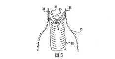
図5は、図4に示した実施形態の側面図である。
図6は、取付け装置に取り付けた補綴の正面図である。
図7は、図6の線7−7におおむね沿って切った断面図である。
図8は、図6に示した保持装置の拡大一部切り欠き図である。
図9は、図8の線9−9におおむね沿って切った断面図である。
図10は、図8の線10−10のおおむね沿って切った断面図である。
図11は、保持ループによって保持した補綴の拡大正面図である。
図12は、保持ループの一部の拡大正面図である。
図13は、補綴と挿入装置のもう一つの実施形態の正面図である。
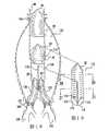
図14は、図13に示す補綴の拡大図である。
図15は、図11に示した実施形態の、体内の径路に挿入する前の状態を示した拡大断面図である。
図16は、図13に示した実施形態の、体内の径路に挿入する前の状態を示した断面図である。
図17は、もう一つの実施形態の、大動脈分岐点の中の定位置に配置した状態を切り欠いて示した正面図である。
図18は、さらにもう一つの実施形態の、大動脈分岐点の中の定位置に配置した状態を切り欠いて示した正面図である。
図19は、図18に示したモジュールの拡大正面図である。
図20は、図19の線20−20におおむね沿って切った断面図である。
図21は、図19の線21−21におおむね沿って切った断面図である。
図22は、図14の実施例の変形例を表した正面図である。
図23は、もう一つの実施例の一部切り欠き正面図である。
図24は、心臓内に位置する補綴装置の状態を切り欠いて示した正面図である。BRIEF DESCRIPTION OF THE DRAWINGS FIG. 1 is a general top view of a clamping ring, according to one embodiment of the present invention.
FIG. 2 is a reduced perspective view showing that the embodiment of FIG. 1 is located within an idealized body path.
FIG. 3 is a front view of the tightening ring before insertion into the body passage.
FIG. 4 is a front view of the tightening ring after it has been introduced into the body path.
FIG. 5 is a side view of the embodiment shown in FIG.
FIG. 6 is a front view of the prosthesis attached to the attachment device.
FIG. 7 is a cross-sectional view taken generally along line 7-7 in FIG.
FIG. 8 is an enlarged partially cutaway view of the holding device shown in FIG.
FIG. 9 is a cross-sectional view taken generally along line 9-9 in FIG.
10 is a cross-sectional view taken generally along line 10-10 of FIG.
FIG. 11 is an enlarged front view of the prosthesis held by the holding loop.
FIG. 12 is an enlarged front view of a part of the holding loop.
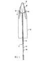
FIG. 13 is a front view of another embodiment of the prosthesis and insertion device.
FIG. 14 is an enlarged view of the prosthesis shown in FIG.
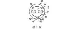
FIG. 15 is an enlarged cross-sectional view showing a state of the embodiment shown in FIG. 11 before being inserted into a body passage.
FIG. 16 is a cross-sectional view showing a state of the embodiment shown in FIG. 13 before being inserted into a body passage.
FIG. 17 is a front view showing another embodiment in which a state of being arranged at a fixed position in the aortic bifurcation point is cut away.
FIG. 18 is a front view showing a state in which it is arranged at a fixed position in the aortic bifurcation point in a further cutaway manner according to another embodiment.
FIG. 19 is an enlarged front view of the module shown in FIG.
20 is a cross-sectional view taken generally along line 20-20 in FIG.
FIG. 21 is a cross-sectional view taken generally along line 21-21 of FIG.
FIG. 22 is a front view showing a modification of the embodiment of FIG.
FIG. 23 is a partially cutaway front view of another embodiment.
FIG. 24 is a front view showing a state of the prosthetic device located in the heart in a cutaway manner.
発明の実施の形態
図面について説明する。複数の図面において、類似した部分に対しては類似した符号番号を使用している。環状弾性締め付けリング30は、図1、8、および10に示すように、複数の弾性ワイヤの素線32から形成することができる。リング30の一つの実施形態は、単一の長さのワイヤで中心軸‘‘C‘‘を有するマンドレル(図示していない)の回りを包み、糸34を使ってその素線を束にして固定することによって形成することができる。糸34は、外科用縫合材から形成することができる。もちろん、リング30は、他にも、単一素線のワイヤを使用する方法、多重素線ワイヤロープのように、螺旋状によりあわせたワイヤからなる複数の素線を使用する方法、あるいは、弾性の高い環状リングを形成する他の適した技術を含む、様々な技術を使って形成することができる。DETAILED DESCRIPTION OF THE INVENTION The drawings will be described. In the drawings, similar reference numerals are used for similar parts. The annular
コイルや素線32の数は、使用するワイヤや適用方法によって変えることができるが、ある実施形態で使用している素線32の数は、図10に示すように、約8本乃至10本である。しかし、コイルまたは素線32の数は、2本乃至100本もしくはそれ以上まで変えることができる。 The number of coils and
様々な直径のワイヤを使用することができるが、個々の素線32は、直径が約.05乃至1mmのものを使用することができる。ある有利な実施形態では、直径が約.1mmのワイヤ素線32を使用することができる。 Although various diameter wires can be used, each
素線32は、ニチノールのようなニッケル−チタン合金をはじめとする、弾性の高い金属またはプラスチック材料からなるものでよい。一般的に、弾性、超弾性、またはマルテンサイト形態のニチノールを使用する。 The
リング30の直径DKは、体内の径路のどの箇所に使用するかによって、かなりの違いがある。大動脈血管移植術に関しては、リングの直径は約30mmが適しており、その他の状況では、リングの直径(DK)は、約6乃至50mmが適当と考えられる。また、実施形態によっては、リングの直径は、13mmが好ましい。The diameter DK of the
図1について説明する。圧縮する前のリング32は、治療する体内の径路36の直径DRよりかなり大きい直径DKを有している。図1に示すように、変形前のリング30の直径方向に正反対の点‘‘A‘‘を互いに向かって歪める。矢印で示すように、この動作により、リング30は、その直径に沿った軸‘‘B‘‘に沿って折りたたまれる。この形状で、リング30は、断面形状を縮小して体内の径路36に挿入することができる。With reference to FIG.
直径に沿った軸‘‘B‘‘に沿って折り曲げた結果、折りたたんだ先端‘‘A‘‘を含むループ38が、折りたたみの直径に沿った軸に並ぶ点‘‘B‘‘と相対的に近位の方向に延在する。ここで使用しているように、‘‘近位‘‘という用語は、血液の流れに対して上流の方向を言い、‘‘遠位‘‘という用語は、血液の流れに対して下流の方向を言う。 As a result of the folding along the axis “B” along the diameter, the
リング30は、一度体内の径路36の中の定位置につくと、リング30がおおむね正弦波形状をとっても血管36の内壁に接触し続ける。初めの推定によると、図2に示した高さHは、半径方向の圧縮の二次関数である。 Once the
図2に示した、プラスチックを変形することなしに、可能な最小曲げ直径DBは、材料、締め付けリング30の厚み、リング30を形成している個々の素線32によって異なる。フックの法則によると、素線32は平行に連結されたばねであると見なすことができ、そのたわみ特性値は加法的であり、その個々の低い放射張力の合計が素線32の数に依存する合計張力と等しくなる。リング30全体を圧縮すると、個々の素線32の曲げ直径は、個々の素線32の最小曲げ直径DBとほぼ一致する。Shown in FIG. 2, without deforming the plastic, minimum bending diameter DB possible, different materials, the thickness of the clamping
推定では、最小曲げ直径DBは、ワイヤの直径の約10倍である。これは、リング30のワイヤの直径は、小さく保つ方がよいということを意味する。しかし、リングが体内の径路36を締め付ける力は、その直径の関数であり、これは、逆にワイヤの直径を大きくした方がよいということを意味する。この駆け引きは、直径が最小曲げ直径を制御する複数の素線32を使用して束を形成し、その合計の直径が締め付け力を制御するように構成することによって最適化することができる。このように、張力が高い締め付けリング30は、比較的小さい圧縮形状にすることが可能である。例えば、4mm乃至6mmという従来の直径を有するカテーテルから取り外すと、リング30はその元の形状に戻り、適度な張力でリング30が体内の径路36の壁に沿ってしっかりと押し付けられる。The estimated minimum bending diameter DB is about 10 times the wire diameter. This means that the wire diameter of the
図3に示すように、補綴40は、環状リング30と移植片42を有するものでもよい。移植片42は、おおむね管形で、一端がリング30に固定されている織物または膜からなる。移植片42は、締め付けリング30の直径DKより小さい直径Dpのものでよい。締め付けリング30と移植片42の間が連結されているので、締め付けリングと移植片42の間の接合点は、直径DKpとなる。締め付けリング30は、管形移植片42の端部を、それ以上拡張できない変形限度まで拡張することができる。このように、リング30は、リングの近位の領域の移植片上で拡張するため、移植片42の直径は、44の領域では徐々に先細となり、さらに、直径が比較的一定の領域46から自由端47まで続く。あるいは、移植片42は、図3で示すように、予め外側に向かって張り出した形状にしておいてもよい。As shown in FIG. 3, the
移植片42は、人間の移植に適合する様々な組織材料であれば、何を利用して形成してもよい。例えば、移植片42は、ダクロン、テフロンまたはその他の素材からなる可撓性の織物または編物で形成することができる。管形移植片42は、その円周が変化しにくい材料からなるのが有利である。また、移植片42の部位46が、修復しようとしている体内の径路36の直径DRとほぼ等しい直径Dpであるのが有利である。The
リング30は、縫合または接着により、領域44と接合することができる。締め付けリング30を、移植片42の内側表面上に配置し、リング30が体内の径路36の壁に抗して拡張した時に、移植片42が管36とリング30の間に挟まるようにするとよい。従って、リング30の直径DKは、移植片42の部位46の直径よりかなり大きいほうがよい。
図4について説明する。補綴40は、左腎動脈50と右腎動脈52に隣接した腹部大動脈48内に位置させることができる。ループ38は、動脈50および52を超えて延在し、部位53は、動脈48および50へつながる開口部のすぐ遠位側に位置している。従って、図5に示すように、動脈48および50への開口部は、リング30の断面がおおむねC字型形状になっているため、環状リング30をそこに隣接して位置させても遮断されることはない。The
FIG. 4 will be described. The
この形状により、リング30は、動脈瘤55と境を接する比較的短い、実質的に変形していない頚部領域54に固定することができる。これは、リング30の少なくとも一部が動脈48および50を通る流れになんら影響せずに頚部54を超えて近位側まで延在しているからである。さらに、締め付けリング30は、その折りたたまれてない形状(図1に示す)まで完全に拡張することがないため、不規則な形状の断面を有する頚部54にも適合することができる。 This shape allows the
例えば、頚部54の断面が円形でない場合された状態が正弦波形状のリング30は、不規則な形状の体内の径路に適合することができる。圧縮していない状態の直径(DK)が、係合先の体内の径路の直径(DR)より大きいリング30を作ることにより、リング30と体内の径路36との間は弾力により継続して係合し、たとえ体内の径路が時間の経過と共に拡張しても、係合し続けることができる。これは、正常に脈動する血圧によって、あるいは時間の経過に伴う血管拡張によって定期的に起こりうる。For example, a sine wave shaped
さらに、リング30の直径(DKP)を移植片42の直径(Dp)より大きくすることにより、使用中の移植片の直径は、体内の径路36の中の定位置に位置するリング30の圧縮状態の断面直径(DK)に近くなる。これにより、移植片42が頚部54の回りに不必要にたまる可能性が減る。In addition, by making the diameter of the ring 30 (DKP ) greater than the diameter (Dp) of the
ここで補綴40を管内の希望の箇所に位置させる方法について述べる。図6に示した保持装置56は、少なくとも二箇所の正反対の位置でリング30に固定することができるため、装置56は、補綴40の軸におおむね平行に延在する。装置56は、一端に通路58を有し、さらに装置56をリング30に固定するための取付け金具60を有していてもよい。あるいは、通路58をワイヤ固定取付け金具(図示していない)と置き換えてもよい。場合によっては、装置56の一端にかえし62を設けてもよい。しかし、多くの場合、かえし62は必要ない。 Here, a method of positioning the
装置56は、図7に示すように、通路58内に延在するワイヤ64とワイヤ64を囲むチューブ66によって係合することができる。都合のよいことに、装置56およびチューブ66は、適度に剛性を有する材料からなっているため、ワイヤ64またはチューブ66を装置56の方向に押すことにより、管36の中の補綴40を移動させることができる。ワイヤ64の直径は、約.3乃至1mmがよい。 The
補綴40は、補綴を遠隔の入口点から修復患部へ移送するための管形カテーテル68の中に圧縮して取り付けることができる。カテーテル68は、例えば、股動脈の切開部分から挿入し、環状リング30を装着したい箇所、例えば腹部大動脈内の定位置まで進ませることができる。定位置についたら、チューブ66を使って、補綴40をカテーテル68から押し出すことができる。特に、外科医が、カテーテル68を固定位置に維持しながら、チューブ66を身体の外側から内側に向けて前進させるため、補綴40は、カテーテルを引き出した後も定位置に残る。希望があれば、取付け金具60をプラチナ、イリジウム、あるいは金などのようなX線不透過性材料とし、X線マーカとしての役割を果たすようにすることもできる。 The
上記のような補綴40の位置決め手順は、適用目的によっては有用であるが、さらに、補綴40の特定の箇所への正確で制御可能な位置決めがより簡単にできるのが望ましい。一度リング30を管の壁に向けて拡張してしまったら、位置を直す際にはリング30の抵抗力に反して行なわなければならない。従って、補綴40がカテーテル68を離れた後も、補綴40が正確な位置につくまでリング30を保持したほうが都合がよい。そのため、図11および12に示す例では、ボーデン管70が伸縮自在にワイヤのループ72を保持している。ループ72は、管70を通って軸方向に延在し、環状リング74を形成し、ボーデン管72の近位の自由端の穴76を通る。この点で、ワイヤループ72のループ型の端部78は、ブロッキングワイヤ80を受容し、ループ78が穴の外側に延在している。
図11について説明する。ボーデン管70は、補綴40の外側に沿って、ループ38に近接する点まで延在している。環状リング74は、ループ38の外周の回りの、その長さのほぼ中央部分に延在し、リング30に固定してある鳩目82に係合している、このように、ブロッキングワイヤ80を軸方向に引き出して、ループ型の端部78を解放することにより、ワイヤループ72を引き出して、リング30を解放して希望の位置で復元力によって開くようにすることができる。Although the positioning procedure of the
FIG. 11 will be described. The
ブロッキングワイヤ80は、ボーデン管70の中の入口点まで戻すことも、あるいは、図11で示すように、間隙71を通ってボーデン管70から取り出すこともできる。
図15について説明する。カテーテル68は、補綴40を取り囲んでおり、補綴40は、一対のチューブ66と、そこを通って延在するワイヤ64とを取り囲んでいる。必要な場合は、ガイドワイヤ104を設けて、まず、カテーテルを希望の箇所へ誘導し、必要な場合に追加の要素とともに同じ箇所に戻ることができるようにそのまま通路を維持しておくこともできる。ループ型のワイヤ72とブロッキングワイヤ80のついたボーデン管70も、カテーテルの内部の、カテーテルと補綴40との間に延在している。The
FIG. 15 will be described. The
図13および図14に示すさらにもう一つの実施形態では、保持機構84が補綴40を圧縮形状に保持し、それを径路の中の希望の位置に正確に位置させる。 In yet another embodiment shown in FIGS. 13 and 14, the retention mechanism 84 holds the
機構84は、移植片42を接合した一対のリング30を有する補綴40’を、カテーテル68の中で圧縮した状態で制御することができる。ガイドワイヤカテーテル86は、補綴40’を通って軸方向に延在している。複数の小環88がカテーテル86の外側に延在している。それぞれの小環88は、ワイヤループ90と接続してあり、ワイヤループ90は、ループ38の自由端に位置する鳩目92と接続してある。 The mechanism 84 can control the
図14を見ると、それぞれのワイヤループ90が摺動可能および取り外し可能に鳩目92を通って延在し、ループ端94を形成している。また、ブロッキングワイヤ96はループ端94を通って延在している。それぞれのリング30の、折りたたみの軸‘‘B‘‘に沿った部分には、ワイヤーループ98が巻き付いており、ワイヤループ98の自由端はブロッキングワイヤ100に係合している。ワイヤループ98はリング30の回りおよびその上を通って、さらにガイドワイヤカテーテル86の外側上を通り、開口部102からカテーテル86の中に入る。移植片42の両端上に取り付けたリング30は、それぞれ同じ部分を有しており、同じ方法で操作する。 Referring to FIG. 14, each wire loop 90 extends slidably and removably through
従って、図14に示すような方向にリング30を折り曲げる程度や近位と遠位の高さを調整するためには、単に患者の外側まで延在する一本のワイヤ103に連結できるワイヤ98を外側に向かって引張るだけでよい。リング30の高さを減らし、圧縮を軽減するには、ワイヤループ98の張りを緩め、リング30の自然な復元力によりリング30の曲げを解放し、リングの高さを減らせばよい。 Therefore, in order to adjust the degree to which the
カテーテル68が希望の箇所に位置したら、すでに説明した技術により、カテーテルからその組立体を取り出すことができる。リング30の圧縮の程度を調節し、装置84が一時的に希望の箇所に位置するように調整することができる。その位置が厳密に正しくないと判断したら、ループ98を操作して装置を再び圧縮し、装置84を新しい位置に再度調整することができる。このように、補綴をすでに解放して、体内の径路に係合した後でも補綴40’の位置を選択的に調整することができる。初めに誤って位置決めしてしまっても、必要に応じて容易に補綴の位置を直すことができる。補綴を希望の箇所に位置させたら、単にブロッキングワイヤ100および96を、カテーテル68を通して組立体から引き出せばよい。これにより、補綴40’が拡張し、取り外すことができなくなる。カテーテル86は、その後、取り出すことができる。 Once the
希望があれば、それぞれのループ98を独立したワイヤで患者の外部につなげてもよい。あるいは、すでに説明したように、ワイヤ98をつなげて、一本のワイヤのみが外に延在するようにすることもできる。 If desired, each
図16は、図13および図14に示した実施形態に使用しているカテーテルの管束であり、カテーテル68から取り外す前の状態を表しており、カテーテル68が補綴40’を取り囲んでいる。補綴40’の中に位置しているのは、ガイドワイヤカテーテル86で、環状リング30の折りたたんだ部分の位置を制御するのに使用する一本もしくはそれ以上のワイヤ103を有している。ガイドワイヤカテーテル86の外側に位置しているのは、ブロッキングワイヤ96および100に相当する一対のワイヤである。 FIG. 16 is a bundle of catheters used in the embodiment shown in FIGS. 13 and 14, and shows a state before being removed from the
本発明のもう一つの実施形態によると、補綴40に、図17に示す補綴106のような一つもしくはそれ以上のモジュールを追加して補うことができる。第2の補綴106は、移植片42による抵抗力に反して外側方向に拡張する環状リング30を使って第1の補綴40に入れ子式に係合している。第2の補綴106は、上側環状リング30’と、下側環状リング30’’とを有する。移植片42に係合するのは上側環状リング30’で、一方、下側環状リング30’’は、遠位の頚部54bに係合する。第2の補綴106が入れ子式に第1の補綴40の中に拡張する量は調整可能で、長さの異なる血管に対し、広い範囲にわたる配置に対応できる。 According to another embodiment of the present invention, the
一対のリング30’および30’’を含む補綴106には、図23に示すように、長手のねじれ防止ワイヤ31を設けることができる。ワイヤ31をリング30’および30’’の回りに取り付けて、補綴106がその長手方向の軸の回りでねじれたり、よじれたりしないように制御し、さらに長手方向に支持するように構成することもできる。ワイヤ31は、ワイヤ31を補綴106の内側に位置させるか、あるいは、ワイヤ31を織物でできた移植片42を通して編み込むことによって移植片42によって覆われている。希望があれば、一本もしくはそれ以上の追加のワイヤ31をリング30’および30’’の外周の回りに設けることもできる。 The
第2の補綴106は、第1の補綴の位置決めに使用したすべてのワイヤを取り除いた後に定位置に残っているガイドワイヤ104を使って、第1の補綴の中に位置させることもできる。その後、第2の補綴106を、第1の補綴40を位置決めした後にその位置に残っているガイドワイヤ104を使って同じ位置に戻すことができる。 The
ガイドワイヤ104は、移植片の開口部も維持する。しかし、実際は、補綴40の中を流れる血液の流れにより、開放され、拡張した吹き流しのような動作を行なう。従って、ガイドワイヤ104の誘導動作により、第2の補綴106は移植片42の内側表面と係合することができる。このように、二つの補綴40および106を組み合わせることにより、補綴40の中への補綴106の拡張の度合いを変更して、頚部54aおよび54bの間で調整可能に広げることができる。
また、補綴40および106は、図22に示すような機構84を使用して位置決めすることができる。すでに補綴40の中に取り付けてある補綴106を、組になった追加のブロッキングワイヤ96’を使って患者の中に挿入することができる。ブロッキングワイヤ96’は、下側ループ94を通り、補綴40の内部を通って延在する。このように、補綴106を独立して、補綴40の中で調節可能に伸縮させて操作することができる。この場合、ワイヤ98と98’は、患者の外側に別々に伸長させ、補綴40と106を独立して操作しやすくすることができる。 The
上記の補綴に類似した補綴を使用して、腹部大動脈48とそれに付随する頚部54aから下側頚部54bを超えて腸骨または骨盤動脈108および110の中に延在する、図18に示すような分岐ステント120を作ることもできる。この場合も、補綴40は、上記のように、頚部54aと係合する。先に説明した補綴106の代わりとして、次に特殊形状の補綴112を使用することができる。図19に示した補綴112は、その上端にリング30を有し、その下端には、一対のリング114を有している。リング114は、単に開口した形状の補綴112の下端を保持するだけなので、圧縮する必要はない。 Using a prosthesis similar to the prosthesis described above, extending from the abdominal aorta 48 and its associated neck 54a beyond the
図20および21に示すように、補綴112の上端は、上記のようなタイプの円形状でよい。また、下端は、補綴112の軸方向に沿って延在し、リング114まで続く二つの分かれた小室を形成する接続部118によって形成される一対の通路を含む二重の管形状でよい。リング114は、補綴112の軸に対して角度をなして位置し、腸骨動脈108および110から入りやすくすることができる。 As shown in FIGS. 20 and 21, the upper end of the
一対の直径の小さい補綴120は、それぞれの腸骨動脈108または110を通って補綴112と係合するように、左右対称に挿入する。特に、上側リング30’’は、リング114を通って入り、移植片42に対して外側方向に拡張する径路116の内部を通る。同時に、それぞれの補綴120のもう一端122は、腸骨動脈108または110で頚部54bと係合する。補綴120のうちの一方は、前に取り付けた補綴の位置決めに使用したものと同じガイドワイヤを使って挿入することができる。しかし、もう一方の補綴120は、そのガイドワイヤとは別に位置決めしなければならない。このため、リング30’’と114に耐X線材料を使用して、リング114の位置決めがしやすいように、また、予め設置したガイドワイヤなしで挿入しなければならない補綴120が、それらのリング114の中を通りやすいようにすることができる。 A pair of
上記のような装置と技術により、外科的処置の間でさえも血液の流れを実質的に遮断することなく、補綴40、40’、120の位置を定めることができる。 With the devices and techniques as described above, the position of the
さらに、補綴40,40’、または120は腎動脈のような交差する血管を実質的に妨げないように構成することができる。同時に、モジュール式の方法を使って生理機能の違いに適合させることもできる。これを、環状リング30をその変形前の形状まで完全に拡張する必要がないという事実と合わせて考えると、異なった様々なステントを常に備えておく必要がないということになる。その代わり、患者のさまざまな状況に適合することのできる、比較的限られた、あるいは、一揃えの寸法を備えておきさえすればよい。 Further, the
リング30が体内の径路に位置している時はC字型形状であるため、補綴を比較的狭い頚部54領域に位置させることができる。リング30は使用中も圧縮された状態を保つため、治療した管を短期間および長期間拡張させるように適応できる。さらに、リング30のばねのバイアス圧力が常にかかるため、径路が不規則な形状をしていても、リング30(と補綴)と体内の径路の壁との間が良好な密着状態に維持される。 When the
上記のような位置決め技術により、補綴を体内の径路の中の希望の箇所に正確に位置させることができる。これは、補綴が取り付けられる時には第1の圧縮形状のまま希望の位置へと移送されるため、補綴と血管径路の間の摩擦を克服する必要なく、位置決めすることができる。一度希望の位置についたら、補綴を起動させて壁に係合させることができる。また、希望があれば、壁に係合させた後でも補綴の位置を変更することもできる。これにより、正確に位置決めができるため、取り外しができない拡張形状になってから補綴の位置を変えなければならないようなことはない。このように、外科医は、(例えば、ガイドワイヤとチューブを使って)かなりの精度で制御することができ、よって、補綴をその最も効果的な位置に正確に位置決めすることができる。 With the positioning technique as described above, the prosthesis can be accurately positioned at a desired position in the body path. This can be positioned without having to overcome the friction between the prosthesis and the blood vessel path because it is transferred to the desired position in the first compressed shape when the prosthesis is attached. Once in the desired position, the prosthesis can be activated to engage the wall. If desired, the position of the prosthesis can be changed even after engaging the wall. Accordingly, since the positioning can be performed accurately, there is no need to change the position of the prosthesis after an expanded shape that cannot be removed. In this way, the surgeon can control with considerable precision (eg, using a guide wire and tube), and thus can accurately position the prosthesis in its most effective position.
また、補綴40は、図24に示すように上行大動脈の罹病部分を交換するのに使用することもできる。大動脈の一部を外科手術により取り除いた後に環状リング30を上行大動脈‘‘D‘‘の残りの部分に取り付けることができる。締め付けリング30は、先に述べたように、大動脈‘‘D‘‘の内側表面に固定される。締め付けリングは、管形の、可撓性スリーブまたは移植片42に接合され、移植片42は機械の心臓弁に接合しやすくするための縫合リング130に接合してある。弁と移植片の詳細は、当業者の知るところであり、本出願の中で明示的に引用している米国特許第5,123,919号で説明している。
移植片42は、関係する組織の量により、さまざまな長さのものを使用できる。移植片42は、図示しているよりもさらに拡張することができ、また、かなり短くすることもできる。例えば、心臓弁を交換するだけでよい場合は、移植片42を、機械の弁132とリング30を連結する短い可撓性のスリーブより少し長くするだけでよい。また、本発明について、限られた数の好ましい実施形態に関して説明してきたが、様々な変更や変形が可能であるということは、当業者によって理解できよう。例えば、ある場合では、この装置は、動脈瘤を治療するための血管ステントとして説明しているが、本発明は、あらゆる装置を内部の径路に固定するのに適用することができる。さらに、本発明のある実施形態では、上記のように、一つもしくはそれ以上の利点しかないものもあるが、代わりにここで特に述べていない他の利点を有するものもあるということは理解できよう。添付の請求の範囲は、その精神と範囲にもとることなく、そのような変形や変更を含むものである。The
The
Claims (51)
Translated fromJapaneseApplications Claiming Priority (4)
| Application Number | Priority Date | Filing Date | Title |
|---|---|---|---|
| DE1996124642DE19624642B4 (en) | 1996-06-20 | 1996-06-20 | Vascular prosthesis and associated application device |
| DE19624642.3 | 1996-06-20 | ||
| DE19633588.4 | 1996-08-20 | ||
| DE19633588ADE19633588A1 (en) | 1996-08-20 | 1996-08-20 | Clamping ring for retaining prosthesis in body passage, e.g. for repair of arterial aneurysms |
Related Parent Applications (1)
| Application Number | Title | Priority Date | Filing Date |
|---|---|---|---|
| JP50252298ADivisionJP4014226B2 (en) | 1996-06-20 | 1997-06-19 | Repair of the body's path by prosthesis |
Related Child Applications (2)
| Application Number | Title | Priority Date | Filing Date |
|---|---|---|---|
| JP2010260645ADivisionJP5350352B2 (en) | 1996-06-20 | 2010-11-22 | Repair of the body's path by prosthesis |
| JP2011108535ADivisionJP5419924B2 (en) | 1996-06-20 | 2011-05-13 | Repair of the body's path by prosthesis |
Publications (4)
| Publication Number | Publication Date |
|---|---|
| JP2008036418Atrue JP2008036418A (en) | 2008-02-21 |
| JP2008036418A6 JP2008036418A6 (en) | 2008-05-08 |
| JP2008036418A5 JP2008036418A5 (en) | 2011-07-21 |
| JP4790672B2 JP4790672B2 (en) | 2011-10-12 |
Family
ID=26026758
Family Applications (4)
| Application Number | Title | Priority Date | Filing Date |
|---|---|---|---|
| JP50252298AExpired - LifetimeJP4014226B2 (en) | 1996-06-20 | 1997-06-19 | Repair of the body's path by prosthesis |
| JP2007186160AExpired - LifetimeJP4790672B2 (en) | 1996-06-20 | 2007-07-17 | Repair of the body's path by prosthesis |
| JP2010260645AExpired - LifetimeJP5350352B2 (en) | 1996-06-20 | 2010-11-22 | Repair of the body's path by prosthesis |
| JP2011108535AExpired - LifetimeJP5419924B2 (en) | 1996-06-20 | 2011-05-13 | Repair of the body's path by prosthesis |
Family Applications Before (1)
| Application Number | Title | Priority Date | Filing Date |
|---|---|---|---|
| JP50252298AExpired - LifetimeJP4014226B2 (en) | 1996-06-20 | 1997-06-19 | Repair of the body's path by prosthesis |
Family Applications After (2)
| Application Number | Title | Priority Date | Filing Date |
|---|---|---|---|
| JP2010260645AExpired - LifetimeJP5350352B2 (en) | 1996-06-20 | 2010-11-22 | Repair of the body's path by prosthesis |
| JP2011108535AExpired - LifetimeJP5419924B2 (en) | 1996-06-20 | 2011-05-13 | Repair of the body's path by prosthesis |
Country Status (11)
| Country | Link |
|---|---|
| US (7) | US8088155B1 (en) |
| EP (2) | EP1595513A3 (en) |
| JP (4) | JP4014226B2 (en) |
| CN (2) | CN1166346C (en) |
| AR (1) | AR007441A1 (en) |
| AT (1) | ATE288233T1 (en) |
| AU (1) | AU3182897A (en) |
| BR (1) | BR9709867A (en) |
| CA (1) | CA2258732C (en) |
| DE (1) | DE69732411T2 (en) |
| WO (1) | WO1997048350A1 (en) |
Families Citing this family (264)
| Publication number | Priority date | Publication date | Assignee | Title |
|---|---|---|---|---|
| EP1595513A3 (en)* | 1996-06-20 | 2010-09-15 | Vascutek Limited | Prosthetic repair of body passages |
| US6395019B2 (en) | 1998-02-09 | 2002-05-28 | Trivascular, Inc. | Endovascular graft |
| US20100318174A1 (en)* | 1998-12-11 | 2010-12-16 | Endologix, Inc. | Implantable vascular graft |
| US6162246A (en)† | 1999-02-16 | 2000-12-19 | Barone; Hector Daniel | Aortic graft and method of treating abdominal aortic aneurysms |
| US6398802B1 (en)* | 1999-06-21 | 2002-06-04 | Scimed Life Systems, Inc. | Low profile delivery system for stent and graft deployment |
| IL131863A0 (en)* | 1999-09-10 | 2001-03-19 | Bruckheimer Elchanan | Intravascular device and method using it |
| US6440164B1 (en) | 1999-10-21 | 2002-08-27 | Scimed Life Systems, Inc. | Implantable prosthetic valve |
| NL1014095C2 (en)* | 2000-01-17 | 2001-07-18 | Cornelis Hendrikus Anna Witten | Implant valve for implantation into a blood vessel. |
| US6602280B2 (en) | 2000-02-02 | 2003-08-05 | Trivascular, Inc. | Delivery system and method for expandable intracorporeal device |
| US6676698B2 (en)* | 2000-06-26 | 2004-01-13 | Rex Medicol, L.P. | Vascular device with valve for approximating vessel wall |
| EP1309289A2 (en) | 2000-08-18 | 2003-05-14 | Atritech, Inc. | Expandable implant devices for filtering blood flow from atrial appendages |
| US6602286B1 (en) | 2000-10-26 | 2003-08-05 | Ernst Peter Strecker | Implantable valve system |
| EP1341487B1 (en)* | 2000-12-15 | 2005-11-23 | Angiomed GmbH & Co. Medizintechnik KG | Stent with valve |
| US20020120328A1 (en) | 2000-12-21 | 2002-08-29 | Pathak Chandrashekhar Prabhakar | Mechanical heart valve packaged in a liquid |
| US6591998B2 (en) | 2000-12-21 | 2003-07-15 | Sulzer Carbomedics Inc. | Leakproof container for implantable prosthetic device |
| US6761733B2 (en)* | 2001-04-11 | 2004-07-13 | Trivascular, Inc. | Delivery system and method for bifurcated endovascular graft |
| US6800090B2 (en)* | 2001-05-14 | 2004-10-05 | Cardiac Dimensions, Inc. | Mitral valve therapy device, system and method |
| US6949122B2 (en)* | 2001-11-01 | 2005-09-27 | Cardiac Dimensions, Inc. | Focused compression mitral valve device and method |
| US6824562B2 (en)* | 2002-05-08 | 2004-11-30 | Cardiac Dimensions, Inc. | Body lumen device anchor, device and assembly |
| US7635387B2 (en)* | 2001-11-01 | 2009-12-22 | Cardiac Dimensions, Inc. | Adjustable height focal tissue deflector |
| US6908478B2 (en)* | 2001-12-05 | 2005-06-21 | Cardiac Dimensions, Inc. | Anchor and pull mitral valve device and method |
| US6976995B2 (en) | 2002-01-30 | 2005-12-20 | Cardiac Dimensions, Inc. | Fixed length anchor and pull mitral valve device and method |
| US6793673B2 (en) | 2002-12-26 | 2004-09-21 | Cardiac Dimensions, Inc. | System and method to effect mitral valve annulus of a heart |
| US7179282B2 (en)* | 2001-12-05 | 2007-02-20 | Cardiac Dimensions, Inc. | Device and method for modifying the shape of a body organ |
| US20100016943A1 (en)* | 2001-12-20 | 2010-01-21 | Trivascular2, Inc. | Method of delivering advanced endovascular graft |
| US7147661B2 (en) | 2001-12-20 | 2006-12-12 | Boston Scientific Santa Rosa Corp. | Radially expandable stent |
| JP4331610B2 (en) | 2001-12-20 | 2009-09-16 | トリバスキュラー2,インコーポレイティド | Advanced endovascular graft |
| US20050209690A1 (en)* | 2002-01-30 | 2005-09-22 | Mathis Mark L | Body lumen shaping device with cardiac leads |
| US7007698B2 (en)* | 2002-04-03 | 2006-03-07 | Boston Scientific Corporation | Body lumen closure |
| US6752828B2 (en)* | 2002-04-03 | 2004-06-22 | Scimed Life Systems, Inc. | Artificial valve |
| CA2877641C (en)* | 2002-05-08 | 2017-01-17 | Cardiac Dimensions Pty. Ltd. | Device and method for modifying the shape of a body organ |
| US20040117003A1 (en)* | 2002-05-28 | 2004-06-17 | The Cleveland Clinic Foundation | Minimally invasive treatment system for aortic aneurysms |
| AU2003285943B2 (en)* | 2002-10-24 | 2008-08-21 | Boston Scientific Limited | Venous valve apparatus and method |
| US7837729B2 (en)* | 2002-12-05 | 2010-11-23 | Cardiac Dimensions, Inc. | Percutaneous mitral valve annuloplasty delivery system |
| US7316708B2 (en)* | 2002-12-05 | 2008-01-08 | Cardiac Dimensions, Inc. | Medical device delivery system |
| US6945957B2 (en) | 2002-12-30 | 2005-09-20 | Scimed Life Systems, Inc. | Valve treatment catheter and methods |
| US7314485B2 (en)* | 2003-02-03 | 2008-01-01 | Cardiac Dimensions, Inc. | Mitral valve device using conditioned shape memory alloy |
| US7399315B2 (en) | 2003-03-18 | 2008-07-15 | Edwards Lifescience Corporation | Minimally-invasive heart valve with cusp positioners |
| US20040220654A1 (en) | 2003-05-02 | 2004-11-04 | Cardiac Dimensions, Inc. | Device and method for modifying the shape of a body organ |
| US20060161169A1 (en)* | 2003-05-02 | 2006-07-20 | Cardiac Dimensions, Inc., A Delaware Corporation | Device and method for modifying the shape of a body organ |
| US20050033416A1 (en)* | 2003-05-02 | 2005-02-10 | Jacques Seguin | Vascular graft and deployment system |
| US7887582B2 (en)* | 2003-06-05 | 2011-02-15 | Cardiac Dimensions, Inc. | Device and method for modifying the shape of a body organ |
| ATE392865T1 (en)* | 2003-10-10 | 2008-05-15 | Cook William A Australia | STENT IMPLANTS WITH WINDOWS |
| FR2863160B1 (en)* | 2003-12-09 | 2006-03-03 | Perouse Laboratoires | DEVICE FOR TREATING A BLOOD VESSEL AND METHOD FOR PREPARING THE SAME |
| US8128681B2 (en) | 2003-12-19 | 2012-03-06 | Boston Scientific Scimed, Inc. | Venous valve apparatus, system, and method |
| US7837728B2 (en) | 2003-12-19 | 2010-11-23 | Cardiac Dimensions, Inc. | Reduced length tissue shaping device |
| US20050137450A1 (en)* | 2003-12-19 | 2005-06-23 | Cardiac Dimensions, Inc., A Washington Corporation | Tapered connector for tissue shaping device |
| US9526616B2 (en) | 2003-12-19 | 2016-12-27 | Cardiac Dimensions Pty. Ltd. | Mitral valve annuloplasty device with twisted anchor |
| US7794496B2 (en)* | 2003-12-19 | 2010-09-14 | Cardiac Dimensions, Inc. | Tissue shaping device with integral connector and crimp |
| US7854761B2 (en) | 2003-12-19 | 2010-12-21 | Boston Scientific Scimed, Inc. | Methods for venous valve replacement with a catheter |
| US8603160B2 (en) | 2003-12-23 | 2013-12-10 | Sadra Medical, Inc. | Method of using a retrievable heart valve anchor with a sheath |
| US8828078B2 (en) | 2003-12-23 | 2014-09-09 | Sadra Medical, Inc. | Methods and apparatus for endovascular heart valve replacement comprising tissue grasping elements |
| US9005273B2 (en) | 2003-12-23 | 2015-04-14 | Sadra Medical, Inc. | Assessing the location and performance of replacement heart valves |
| US7381219B2 (en) | 2003-12-23 | 2008-06-03 | Sadra Medical, Inc. | Low profile heart valve and delivery system |
| US7445631B2 (en) | 2003-12-23 | 2008-11-04 | Sadra Medical, Inc. | Methods and apparatus for endovascularly replacing a patient's heart valve |
| US20120041550A1 (en) | 2003-12-23 | 2012-02-16 | Sadra Medical, Inc. | Methods and Apparatus for Endovascular Heart Valve Replacement Comprising Tissue Grasping Elements |
| US20050137687A1 (en) | 2003-12-23 | 2005-06-23 | Sadra Medical | Heart valve anchor and method |
| US8579962B2 (en) | 2003-12-23 | 2013-11-12 | Sadra Medical, Inc. | Methods and apparatus for performing valvuloplasty |
| US20050137694A1 (en) | 2003-12-23 | 2005-06-23 | Haug Ulrich R. | Methods and apparatus for endovascularly replacing a patient's heart valve |
| US7780725B2 (en) | 2004-06-16 | 2010-08-24 | Sadra Medical, Inc. | Everting heart valve |
| US9526609B2 (en) | 2003-12-23 | 2016-12-27 | Boston Scientific Scimed, Inc. | Methods and apparatus for endovascularly replacing a patient's heart valve |
| US8182528B2 (en) | 2003-12-23 | 2012-05-22 | Sadra Medical, Inc. | Locking heart valve anchor |
| US11278398B2 (en) | 2003-12-23 | 2022-03-22 | Boston Scientific Scimed, Inc. | Methods and apparatus for endovascular heart valve replacement comprising tissue grasping elements |
| US8840663B2 (en) | 2003-12-23 | 2014-09-23 | Sadra Medical, Inc. | Repositionable heart valve method |
| US8343213B2 (en) | 2003-12-23 | 2013-01-01 | Sadra Medical, Inc. | Leaflet engagement elements and methods for use thereof |
| US7959666B2 (en) | 2003-12-23 | 2011-06-14 | Sadra Medical, Inc. | Methods and apparatus for endovascularly replacing a heart valve |
| US7803178B2 (en) | 2004-01-30 | 2010-09-28 | Trivascular, Inc. | Inflatable porous implants and methods for drug delivery |
| CA2813136A1 (en)* | 2004-02-27 | 2005-09-15 | Aortx, Inc. | Prosthetic heart valve delivery systems and methods |
| AU2005262541B2 (en)* | 2004-06-16 | 2011-04-21 | Cook Incorporated | Thoracic deployment device and stent graft |
| US7566343B2 (en) | 2004-09-02 | 2009-07-28 | Boston Scientific Scimed, Inc. | Cardiac valve, system, and method |
| DE602005023033D1 (en)* | 2004-09-21 | 2010-09-30 | Cook Inc | STENT GRAFT CONNECTION ARRANGEMENT |
| US20060095117A1 (en)* | 2004-11-03 | 2006-05-04 | Popelar Carl F | Apparatus and method for temporarily clamping a tubular graft to a prosthetic cardiac valve |
| EP1807022A2 (en)* | 2004-11-03 | 2007-07-18 | Jacques Seguin | Vascular graft and deployment system |
| EP1855619A4 (en) | 2005-01-20 | 2013-10-02 | Cardiac Dimensions Inc | Tissue shaping device |
| DE102005003632A1 (en) | 2005-01-20 | 2006-08-17 | Fraunhofer-Gesellschaft zur Förderung der angewandten Forschung e.V. | Catheter for the transvascular implantation of heart valve prostheses |
| US7854755B2 (en) | 2005-02-01 | 2010-12-21 | Boston Scientific Scimed, Inc. | Vascular catheter, system, and method |
| US20060173490A1 (en)* | 2005-02-01 | 2006-08-03 | Boston Scientific Scimed, Inc. | Filter system and method |
| US7780722B2 (en)* | 2005-02-07 | 2010-08-24 | Boston Scientific Scimed, Inc. | Venous valve apparatus, system, and method |
| US7670368B2 (en)* | 2005-02-07 | 2010-03-02 | Boston Scientific Scimed, Inc. | Venous valve apparatus, system, and method |
| US7867274B2 (en) | 2005-02-23 | 2011-01-11 | Boston Scientific Scimed, Inc. | Valve apparatus, system and method |
| US7722666B2 (en) | 2005-04-15 | 2010-05-25 | Boston Scientific Scimed, Inc. | Valve apparatus, system and method |
| US7962208B2 (en) | 2005-04-25 | 2011-06-14 | Cardiac Pacemakers, Inc. | Method and apparatus for pacing during revascularization |
| US20060253193A1 (en)* | 2005-05-03 | 2006-11-09 | Lichtenstein Samuel V | Mechanical means for controlling blood pressure |
| EP1885289B1 (en)* | 2005-06-01 | 2013-01-09 | William A. Cook Australia Pty. Ltd. | Side branch stent graft |
| US8012198B2 (en) | 2005-06-10 | 2011-09-06 | Boston Scientific Scimed, Inc. | Venous valve, system, and method |
| FR2887139B1 (en)* | 2005-06-15 | 2008-04-25 | Perouse Soc Par Actions Simpli | DEVICE FOR TREATING A BLOOD VESSEL. |
| WO2007013108A1 (en)* | 2005-07-27 | 2007-02-01 | Sango S.A.S Di Cattani Rita E C. | Endovenous stent and venous neovalvular endobioprosthesis |
| US7569071B2 (en)* | 2005-09-21 | 2009-08-04 | Boston Scientific Scimed, Inc. | Venous valve, system, and method with sinus pocket |
| WO2007054015A1 (en)* | 2005-11-09 | 2007-05-18 | Ning Wen | An artificial heart valve stent and weaving method thereof |
| US20090048656A1 (en)* | 2005-11-09 | 2009-02-19 | Ning Wen | Delivery Device for Delivering a Self-Expanding Stent |
| FR2894131B1 (en)* | 2005-12-02 | 2008-12-05 | Perouse Soc Par Actions Simpli | DEVICE FOR TREATING A BLOOD VESSEL, AND ASSOCIATED TREATMENT NECESSARY. |
| US20070213813A1 (en) | 2005-12-22 | 2007-09-13 | Symetis Sa | Stent-valves for valve replacement and associated methods and systems for surgery |
| JP4624466B2 (en)* | 2006-01-01 | 2011-02-02 | シフリン、エドワード ジー. | Apparatus and method for vascular graft or stent graft delivery and fixation at both ends |
| US7799038B2 (en)* | 2006-01-20 | 2010-09-21 | Boston Scientific Scimed, Inc. | Translumenal apparatus, system, and method |
| US20070173924A1 (en)* | 2006-01-23 | 2007-07-26 | Daniel Gelbart | Axially-elongating stent and method of deployment |
| EP1983933B1 (en)* | 2006-02-13 | 2013-01-23 | William A. Cook Australia Pty. Ltd. | Side branch stent graft construction |
| EP1988851A2 (en) | 2006-02-14 | 2008-11-12 | Sadra Medical, Inc. | Systems and methods for delivering a medical implant |
| US8147541B2 (en) | 2006-02-27 | 2012-04-03 | Aortx, Inc. | Methods and devices for delivery of prosthetic heart valves and other prosthetics |
| US7749266B2 (en)* | 2006-02-27 | 2010-07-06 | Aortx, Inc. | Methods and devices for delivery of prosthetic heart valves and other prosthetics |
| US20070270933A1 (en)* | 2006-03-09 | 2007-11-22 | Abbott Laboratories | Stent having contoured proximal end |
| US8167929B2 (en)* | 2006-03-09 | 2012-05-01 | Abbott Laboratories | System and method for delivering a stent to a bifurcated vessel |
| CN101045022B (en)* | 2006-03-30 | 2010-08-25 | 温宁 | Self-expanding stent axial wire-drawing tensioning mechanism |
| US7503932B2 (en)* | 2006-04-11 | 2009-03-17 | Cardiac Dimensions, Inc. | Mitral valve annuloplasty device with vena cava anchor |
| CA2654314A1 (en)* | 2006-06-01 | 2007-12-06 | Mor Research Applications Ltd. | Methods and devices for treatment of cardiac valves |
| US20070287879A1 (en)* | 2006-06-13 | 2007-12-13 | Daniel Gelbart | Mechanical means for controlling blood pressure |
| US8500799B2 (en) | 2006-06-20 | 2013-08-06 | Cardiacmd, Inc. | Prosthetic heart valves, support structures and systems and methods for implanting same |
| EP2035723A4 (en) | 2006-06-20 | 2011-11-30 | Aortx Inc | Torque shaft and torque drive |
| WO2007149933A2 (en) | 2006-06-21 | 2007-12-27 | Aortx, Inc. | Prosthetic valve implantation systems |
| US11285005B2 (en) | 2006-07-17 | 2022-03-29 | Cardiac Dimensions Pty. Ltd. | Mitral valve annuloplasty device with twisted anchor |
| US20080126131A1 (en)* | 2006-07-17 | 2008-05-29 | Walgreen Co. | Predictive Modeling And Risk Stratification Of A Medication Therapy Regimen |
| GB0620495D0 (en)* | 2006-10-16 | 2006-11-22 | Anson Medical Ltd | Apparatus and method for positioning a stent graft |
| WO2008091493A1 (en) | 2007-01-08 | 2008-07-31 | California Institute Of Technology | In-situ formation of a valve |
| EP2444031B1 (en)* | 2007-01-19 | 2015-07-15 | Medtronic, Inc. | Stent delivery device |
| US7967853B2 (en)* | 2007-02-05 | 2011-06-28 | Boston Scientific Scimed, Inc. | Percutaneous valve, system and method |
| JP5604110B2 (en)* | 2007-02-05 | 2014-10-08 | ボストン サイエンティフィック リミテッド | System for delivering a valve |
| US20080288045A1 (en)* | 2007-02-22 | 2008-11-20 | Mohsin Saeed | Apparatus and method for implantation of a bifurcated endovascular prosthesis |
| US8821567B2 (en) | 2007-02-22 | 2014-09-02 | Mohsin Saeed | Apparatus and method for implantation of a bifurcated endovascular prosthesis |
| FR2913879B1 (en)* | 2007-03-21 | 2009-06-12 | Perouse Soc Par Actions Simpli | DEVICE FOR LAGGING A RADIALLY EXPANSIBLE IMPLANT, NECESSARY FOR TREATMENT AND METHOD OF RELAUNCHING |
| US7896915B2 (en) | 2007-04-13 | 2011-03-01 | Jenavalve Technology, Inc. | Medical device for treating a heart valve insufficiency |
| US8092510B2 (en)* | 2007-07-25 | 2012-01-10 | Cook Medical Technologies Llc | Retention wire for self-expanding stent |
| US8828079B2 (en)* | 2007-07-26 | 2014-09-09 | Boston Scientific Scimed, Inc. | Circulatory valve, system and method |
| US9237959B2 (en) | 2007-08-17 | 2016-01-19 | Cook Medical Technologies Llc | Stent and barb |
| US8834551B2 (en) | 2007-08-31 | 2014-09-16 | Rex Medical, L.P. | Vascular device with valve for approximating vessel wall |
| US8226701B2 (en) | 2007-09-26 | 2012-07-24 | Trivascular, Inc. | Stent and delivery system for deployment thereof |
| US8663309B2 (en) | 2007-09-26 | 2014-03-04 | Trivascular, Inc. | Asymmetric stent apparatus and method |
| US8066755B2 (en) | 2007-09-26 | 2011-11-29 | Trivascular, Inc. | System and method of pivoted stent deployment |
| US10159557B2 (en) | 2007-10-04 | 2018-12-25 | Trivascular, Inc. | Modular vascular graft for low profile percutaneous delivery |
| EP2211774B1 (en)* | 2007-10-11 | 2016-09-28 | Kirk Promotion LTD. | Implantable tissue connector |
| US8083789B2 (en) | 2007-11-16 | 2011-12-27 | Trivascular, Inc. | Securement assembly and method for expandable endovascular device |
| US8328861B2 (en) | 2007-11-16 | 2012-12-11 | Trivascular, Inc. | Delivery system and method for bifurcated graft |
| US7892276B2 (en) | 2007-12-21 | 2011-02-22 | Boston Scientific Scimed, Inc. | Valve with delayed leaflet deployment |
| US20090171456A1 (en)* | 2007-12-28 | 2009-07-02 | Kveen Graig L | Percutaneous heart valve, system, and method |
| US9044318B2 (en) | 2008-02-26 | 2015-06-02 | Jenavalve Technology Gmbh | Stent for the positioning and anchoring of a valvular prosthesis |
| BR112012021347A2 (en) | 2008-02-26 | 2019-09-24 | Jenavalve Tecnology Inc | stent for positioning and anchoring a valve prosthesis at an implantation site in a patient's heart |
| WO2009148607A1 (en) | 2008-06-04 | 2009-12-10 | Gore Enterprise Holdings, Inc. | Controlled deployable medical device and method of making the same |
| CA2727000C (en)* | 2008-06-04 | 2014-01-07 | Gore Enterprise Holdings, Inc. | Controlled deployable medical device and method of making the same |
| US20100076470A1 (en) | 2008-09-22 | 2010-03-25 | Tyco Healthcare Group Lp | Methods and Devices for Sheath Compression |
| US8006594B2 (en)* | 2008-08-11 | 2011-08-30 | Cardiac Dimensions, Inc. | Catheter cutting tool |
| EP3238661B1 (en) | 2008-10-10 | 2019-05-22 | Boston Scientific Scimed, Inc. | Medical devices and delivery systems for delivering medical devices |
| US8876807B2 (en) | 2009-01-19 | 2014-11-04 | W. L. Gore & Associates, Inc. | Forced deployment sequence |
| US8858610B2 (en) | 2009-01-19 | 2014-10-14 | W. L. Gore & Associates, Inc. | Forced deployment sequence |
| AU2010236349B2 (en)* | 2009-04-15 | 2015-04-02 | Microvention, Inc. | Implant delivery system |
| WO2010128469A1 (en) | 2009-05-05 | 2010-11-11 | Deliverance Ltd. | Device for sealing perforations and sustaining flow |
| US9095456B2 (en) | 2009-10-13 | 2015-08-04 | Cook Medical Technologies Llc | Paraplegia prevention stent graft |
| EP3034036B1 (en) | 2009-10-13 | 2019-09-11 | Cook Medical Technologies LLC | Paraplegia prevention stent graft |
| EP2506799A4 (en) | 2009-12-01 | 2014-10-29 | Altura Medical Inc | Modular endograft devices and associated systems and methods |
| DE102010008338A1 (en)* | 2010-02-17 | 2011-08-18 | Transcatheter Technologies GmbH, 93053 | Device intended to be attached to or attached to a catheter, catheter and method |
| AU2011240927B2 (en) | 2010-04-14 | 2015-07-16 | Microvention, Inc. | Implant delivery device |
| AU2010201676B1 (en)* | 2010-04-23 | 2010-07-22 | Cook Medical Technologies Llc | Curve forming stent graft |
| US8292951B2 (en)* | 2010-04-29 | 2012-10-23 | Medtronic Vascular, Inc. | Tethered pop up branch structure stent graft and method |
| US9402754B2 (en) | 2010-05-18 | 2016-08-02 | Abbott Cardiovascular Systems, Inc. | Expandable endoprostheses, systems, and methods for treating a bifurcated lumen |
| US10856978B2 (en) | 2010-05-20 | 2020-12-08 | Jenavalve Technology, Inc. | Catheter system |
| WO2011147849A1 (en) | 2010-05-25 | 2011-12-01 | Jenavalve Technology Inc. | Prosthetic heart valve and transcatheter delivered endoprosthesis comprising a prosthetic heart valve and a stent |
| US9326872B2 (en) | 2010-08-17 | 2016-05-03 | W. L. Gore & Associates, Inc. | Forced deployment sequence handle assembly with independent actuating mechanism |
| AU2011300644B2 (en) | 2010-09-10 | 2015-08-20 | Symetis Sa | Valve replacement devices and a system comprising the valve replacement device and a delivery device therefor |
| WO2012040240A1 (en) | 2010-09-20 | 2012-03-29 | Altura Medical, Inc. | Stent graft delivery systems and associated methods |
| EP2658483B1 (en)* | 2010-12-30 | 2018-07-11 | Boston Scientific Scimed, Inc. | Loading basket for a stent delivery system |
| GB2488986B (en) | 2011-03-08 | 2013-07-10 | Cook Medical Technologies Llc | Introducer assembly and carrier element for a medical device |
| US9744033B2 (en) | 2011-04-01 | 2017-08-29 | W.L. Gore & Associates, Inc. | Elastomeric leaflet for prosthetic heart valves |
| GB201106017D0 (en)* | 2011-04-08 | 2011-05-25 | Lombard Medical Plc | Apparatus for deploying a stent graft |
| EP3583916B1 (en) | 2011-04-28 | 2023-12-06 | Cook Medical Technologies LLC | Apparatus for facilitating deployment of an endoluminal prosthesis |
| EP2520251A1 (en) | 2011-05-05 | 2012-11-07 | Symetis SA | Method and Apparatus for Compressing Stent-Valves |
| GB201109305D0 (en) | 2011-06-03 | 2011-07-20 | Vascutek Ltd | Method and apparatus for controlling the deployment of a stent |
| US10117765B2 (en) | 2011-06-14 | 2018-11-06 | W.L. Gore Associates, Inc | Apposition fiber for use in endoluminal deployment of expandable implants |
| US8998976B2 (en) | 2011-07-12 | 2015-04-07 | Boston Scientific Scimed, Inc. | Coupling system for medical devices |
| US9668859B2 (en) | 2011-08-05 | 2017-06-06 | California Institute Of Technology | Percutaneous heart valve delivery systems |
| US9554806B2 (en) | 2011-09-16 | 2017-01-31 | W. L. Gore & Associates, Inc. | Occlusive devices |
| US8728148B2 (en) | 2011-11-09 | 2014-05-20 | Cook Medical Technologies Llc | Diameter reducing tie arrangement for endoluminal prosthesis |
| US9877858B2 (en) | 2011-11-14 | 2018-01-30 | W. L. Gore & Associates, Inc. | External steerable fiber for use in endoluminal deployment of expandable devices |
| US9782282B2 (en) | 2011-11-14 | 2017-10-10 | W. L. Gore & Associates, Inc. | External steerable fiber for use in endoluminal deployment of expandable devices |
| US8951243B2 (en) | 2011-12-03 | 2015-02-10 | Boston Scientific Scimed, Inc. | Medical device handle |
| WO2013112547A1 (en) | 2012-01-25 | 2013-08-01 | Boston Scientific Scimed, Inc. | Valve assembly with a bioabsorbable gasket and a replaceable valve implant |
| EP2818139A4 (en) | 2012-02-24 | 2015-10-21 | Terumo Corp | Stent-graft delivery device |
| US9375308B2 (en) | 2012-03-13 | 2016-06-28 | W. L. Gore & Associates, Inc. | External steerable fiber for use in endoluminal deployment of expandable devices |
| US8992595B2 (en) | 2012-04-04 | 2015-03-31 | Trivascular, Inc. | Durable stent graft with tapered struts and stable delivery methods and devices |
| US9498363B2 (en) | 2012-04-06 | 2016-11-22 | Trivascular, Inc. | Delivery catheter for endovascular device |
| US9168122B2 (en) | 2012-04-26 | 2015-10-27 | Rex Medical, L.P. | Vascular device and method for valve leaflet apposition |
| US9883941B2 (en) | 2012-06-19 | 2018-02-06 | Boston Scientific Scimed, Inc. | Replacement heart valve |
| CA2881535A1 (en) | 2012-08-10 | 2014-02-13 | Altura Medical, Inc. | Stent delivery systems and associated methods |
| US11439525B2 (en) | 2012-12-27 | 2022-09-13 | Venus Medtech (Hangzhou) Inc. | Implant delivery device adapted to be attached to or interconnected with a catheter, catheter and method |
| WO2014144247A1 (en) | 2013-03-15 | 2014-09-18 | Arash Kheradvar | Handle mechanism and functionality for repositioning and retrieval of transcatheter heart valves |
| WO2014144809A1 (en) | 2013-03-15 | 2014-09-18 | Altura Medical, Inc. | Endograft device delivery systems and associated methods |
| US11911258B2 (en) | 2013-06-26 | 2024-02-27 | W. L. Gore & Associates, Inc. | Space filling devices |
| EP2832317B1 (en)* | 2013-07-31 | 2017-02-15 | Venus MedTech (HangZhou), Inc. | Implant delivery device for folding or unfolding a medical implant based on a knot |
| CN105491978A (en) | 2013-08-30 | 2016-04-13 | 耶拿阀门科技股份有限公司 | Radially collapsible frame for a prosthetic valve and method for manufacturing such a frame |
| US9668861B2 (en) | 2014-03-15 | 2017-06-06 | Rex Medical, L.P. | Vascular device for treating venous valve insufficiency |
| US10149758B2 (en) | 2014-04-01 | 2018-12-11 | Medtronic, Inc. | System and method of stepped deployment of prosthetic heart valve |
| US10154904B2 (en) | 2014-04-28 | 2018-12-18 | Edwards Lifesciences Corporation | Intravascular introducer devices |
| US10195025B2 (en) | 2014-05-12 | 2019-02-05 | Edwards Lifesciences Corporation | Prosthetic heart valve |
| US10959826B2 (en) | 2014-10-16 | 2021-03-30 | Cook Medical Technology LLC | Support structure for scalloped grafts |
| US9901445B2 (en) | 2014-11-21 | 2018-02-27 | Boston Scientific Scimed, Inc. | Valve locking mechanism |
| WO2016115375A1 (en) | 2015-01-16 | 2016-07-21 | Boston Scientific Scimed, Inc. | Displacement based lock and release mechanism |
| US9861477B2 (en) | 2015-01-26 | 2018-01-09 | Boston Scientific Scimed Inc. | Prosthetic heart valve square leaflet-leaflet stitch |
| WO2016126524A1 (en) | 2015-02-03 | 2016-08-11 | Boston Scientific Scimed, Inc. | Prosthetic heart valve having tubular seal |
| US9788942B2 (en) | 2015-02-03 | 2017-10-17 | Boston Scientific Scimed Inc. | Prosthetic heart valve having tubular seal |
| US10426617B2 (en) | 2015-03-06 | 2019-10-01 | Boston Scientific Scimed, Inc. | Low profile valve locking mechanism and commissure assembly |
| US10285809B2 (en) | 2015-03-06 | 2019-05-14 | Boston Scientific Scimed Inc. | TAVI anchoring assist device |
| US10080652B2 (en) | 2015-03-13 | 2018-09-25 | Boston Scientific Scimed, Inc. | Prosthetic heart valve having an improved tubular seal |
| EP3270825B1 (en) | 2015-03-20 | 2020-04-22 | JenaValve Technology, Inc. | Heart valve prosthesis delivery system |
| US10709555B2 (en) | 2015-05-01 | 2020-07-14 | Jenavalve Technology, Inc. | Device and method with reduced pacemaker rate in heart valve replacement |
| CA2986047C (en) | 2015-05-14 | 2020-11-10 | W. L. Gore & Associates, Inc. | Devices and methods for occlusion of an atrial appendage |
| WO2017004377A1 (en) | 2015-07-02 | 2017-01-05 | Boston Scientific Scimed, Inc. | Adjustable nosecone |
| US10195392B2 (en) | 2015-07-02 | 2019-02-05 | Boston Scientific Scimed, Inc. | Clip-on catheter |
| US9974650B2 (en) | 2015-07-14 | 2018-05-22 | Edwards Lifesciences Corporation | Prosthetic heart valve |
| US10136991B2 (en) | 2015-08-12 | 2018-11-27 | Boston Scientific Scimed Inc. | Replacement heart valve implant |
| US10179041B2 (en) | 2015-08-12 | 2019-01-15 | Boston Scientific Scimed Icn. | Pinless release mechanism |
| KR101779460B1 (en)* | 2015-09-11 | 2017-09-18 | 문병주 | Artificial blood vessel |
| CN108472136B (en) | 2015-12-14 | 2020-11-24 | 美敦力瓦斯科尔勒公司 | Devices and methods for transcatheter valve loading and implantation |
| US10342660B2 (en) | 2016-02-02 | 2019-07-09 | Boston Scientific Inc. | Tensioned sheathing aids |
| US10179043B2 (en) | 2016-02-12 | 2019-01-15 | Edwards Lifesciences Corporation | Prosthetic heart valve having multi-level sealing member |
| US10893938B2 (en) | 2016-03-03 | 2021-01-19 | Medtronic Vascular, Inc. | Stented prosthesis delivery system having a bumper |
| US10420642B2 (en) | 2016-03-14 | 2019-09-24 | Medtronic Vascular, Inc. | Transcatheter stented prosthetic heart valve delivery devices |
| CN108834399B (en) | 2016-03-14 | 2024-06-11 | 美敦力瓦斯科尔勒公司 | Stented prosthetic heart valve with wrap and delivery device |
| US10583005B2 (en) | 2016-05-13 | 2020-03-10 | Boston Scientific Scimed, Inc. | Medical device handle |
| WO2017195125A1 (en) | 2016-05-13 | 2017-11-16 | Jenavalve Technology, Inc. | Heart valve prosthesis delivery system and method for delivery of heart valve prosthesis with introducer sheath and loading system |
| US10201416B2 (en) | 2016-05-16 | 2019-02-12 | Boston Scientific Scimed, Inc. | Replacement heart valve implant with invertible leaflets |
| EP3903732B1 (en) | 2016-06-13 | 2025-07-30 | Bolton Medical, Inc. | Devices for reinforcing fenestrations in prosthetic implants |
| AU2017306141A1 (en) | 2016-08-02 | 2019-03-07 | Aortica Corporation | Systems, devices, and methods for coupling a prosthetic implant to a fenestrated body |
| GB201615219D0 (en) | 2016-09-07 | 2016-10-19 | Vascutek Ltd And Univ Medical Center Hamburg-Eppendorf (Uke) | Hybrid prosthesis and delivery system |
| GB2554670B (en) | 2016-09-30 | 2022-01-05 | Vascutek Ltd | A vascular graft |
| US10813749B2 (en) | 2016-12-20 | 2020-10-27 | Edwards Lifesciences Corporation | Docking device made with 3D woven fabric |
| WO2018138658A1 (en) | 2017-01-27 | 2018-08-02 | Jenavalve Technology, Inc. | Heart valve mimicry |
| WO2018156850A1 (en) | 2017-02-24 | 2018-08-30 | Bolton Medical, Inc. | Stent graft with fenestration lock |
| WO2018156849A1 (en) | 2017-02-24 | 2018-08-30 | Bolton Medical, Inc. | Vascular prosthesis with fenestration ring and methods of use |
| WO2018156851A1 (en) | 2017-02-24 | 2018-08-30 | Bolton Medical, Inc. | Vascular prosthesis with moveable fenestration |
| EP3534837A1 (en) | 2017-02-24 | 2019-09-11 | Bolton Medical, Inc. | Constrainable stent graft, delivery system and methods of use |
| WO2018156848A1 (en) | 2017-02-24 | 2018-08-30 | Bolton Medical, Inc. | Vascular prosthesis with crimped adapter and methods of use |
| EP3932373B1 (en)* | 2017-02-24 | 2022-12-21 | Bolton Medical, Inc. | Delivery system for radially constricting a stent graft |
| WO2018156847A1 (en) | 2017-02-24 | 2018-08-30 | Bolton Medical, Inc. | Delivery system and method to radially constrict a stent graft |
| ES2863978T3 (en) | 2017-02-24 | 2021-10-13 | Bolton Medical Inc | System for radially constricting a stent graft |
| WO2018156854A1 (en) | 2017-02-24 | 2018-08-30 | Bolton Medical, Inc. | Radially adjustable stent graft delivery system |
| ES2954897T3 (en) | 2017-02-24 | 2023-11-27 | Bolton Medical Inc | Constrained Wrap Stent Graft Delivery System |
| US10561497B2 (en) | 2017-03-07 | 2020-02-18 | Medtronic Vascular, Inc. | Delivery system having a short capsule segment and a cinch mechanism and methods of use thereof |
| CA3055567C (en) | 2017-03-08 | 2021-11-23 | W. L. Gore & Associates, Inc. | Steering wire attach for angulation |
| US10390953B2 (en) | 2017-03-08 | 2019-08-27 | Cardiac Dimensions Pty. Ltd. | Methods and devices for reducing paravalvular leakage |
| GB2562065A (en) | 2017-05-02 | 2018-11-07 | Vascutek Ltd | Endoprosthesis |
| GB201707929D0 (en) | 2017-05-17 | 2017-06-28 | Vascutek Ltd | Tubular medical device |
| US10828154B2 (en) | 2017-06-08 | 2020-11-10 | Boston Scientific Scimed, Inc. | Heart valve implant commissure support structure |
| EP3661458A1 (en) | 2017-08-01 | 2020-06-10 | Boston Scientific Scimed, Inc. | Medical implant locking mechanism |
| US10939996B2 (en) | 2017-08-16 | 2021-03-09 | Boston Scientific Scimed, Inc. | Replacement heart valve commissure assembly |
| JP7271510B2 (en) | 2017-09-25 | 2023-05-11 | ボルトン メディカル インコーポレイテッド | Systems, devices and methods for coupling prosthetic implants to fenestrated bodies |
| GB201715658D0 (en) | 2017-09-27 | 2017-11-08 | Vascutek Ltd | An endoluminal device |
| US11173023B2 (en) | 2017-10-16 | 2021-11-16 | W. L. Gore & Associates, Inc. | Medical devices and anchors therefor |
| CN110121319B (en) | 2017-10-31 | 2023-05-09 | 波顿医疗公司 | Distal torque component, delivery system, and method of use thereof |
| EP3740160A2 (en) | 2018-01-19 | 2020-11-25 | Boston Scientific Scimed Inc. | Inductance mode deployment sensors for transcatheter valve system |
| US11246625B2 (en) | 2018-01-19 | 2022-02-15 | Boston Scientific Scimed, Inc. | Medical device delivery system with feedback loop |
| EP3749252A1 (en) | 2018-02-07 | 2020-12-16 | Boston Scientific Scimed, Inc. | Medical device delivery system with alignment feature |
| EP3758651B1 (en) | 2018-02-26 | 2022-12-07 | Boston Scientific Scimed, Inc. | Embedded radiopaque marker in adaptive seal |
| CN112399836B (en) | 2018-05-15 | 2024-10-15 | 波士顿科学国际有限公司 | Replacement heart valve commissure assembly |
| US11241310B2 (en) | 2018-06-13 | 2022-02-08 | Boston Scientific Scimed, Inc. | Replacement heart valve delivery device |
| AU2018439076B2 (en) | 2018-08-31 | 2022-07-07 | W. L. Gore & Associates, Inc. | Apparatus, system, and method for steering an implantable medical device |
| US12114863B2 (en) | 2018-12-05 | 2024-10-15 | Microvention, Inc. | Implant delivery system |
| US11241312B2 (en) | 2018-12-10 | 2022-02-08 | Boston Scientific Scimed, Inc. | Medical device delivery system including a resistance member |
| GB201820898D0 (en) | 2018-12-20 | 2019-02-06 | Vascutek Ltd | Stent device |
| CN111374814B (en)* | 2018-12-28 | 2025-03-18 | 杭州唯强医疗科技有限公司 | Adjustable curved sheath tube and stent delivery device |
| WO2020135456A1 (en)* | 2018-12-28 | 2020-07-02 | 杭州唯强医疗科技有限公司 | Adjustable curved sheath tube and stent delivery device |
| WO2020179697A1 (en)* | 2019-03-06 | 2020-09-10 | 川澄化学工業株式会社 | Stent |
| EP3962417A4 (en) | 2019-05-02 | 2023-01-18 | University of Maryland, Baltimore | VALVE TRANSLOCATION DEVICE AND METHODS FOR TREATMENT OF FUNCTIONAL VALVE REGURGITATION |
| US11439504B2 (en) | 2019-05-10 | 2022-09-13 | Boston Scientific Scimed, Inc. | Replacement heart valve with improved cusp washout and reduced loading |
| CN110227207B (en)* | 2019-07-16 | 2024-07-23 | 南微医学科技股份有限公司 | Medical drainage support |
| US20230346537A1 (en)* | 2020-11-13 | 2023-11-02 | Xeltis Ag | Graft Device for Endogenous Tissue Restoration in Between Two Tubular Structures |
| JP2023554000A (en) | 2020-12-14 | 2023-12-26 | カーディアック・ディメンションズ・プロプライエタリー・リミテッド | Modular preloaded medical implants and delivery systems |
| WO2024081569A1 (en)* | 2022-10-10 | 2024-04-18 | Edwards Lifesciences Corporation | Compliance implant devices with elastic tubes |
| WO2024102411A1 (en) | 2022-11-09 | 2024-05-16 | Jenavalve Technology, Inc. | Catheter system for sequential deployment of an expandable implant |
Citations (13)
| Publication number | Priority date | Publication date | Assignee | Title |
|---|---|---|---|---|
| US4562596A (en)* | 1984-04-25 | 1986-01-07 | Elliot Kornberg | Aortic graft, device and method for performing an intraluminal abdominal aortic aneurysm repair |
| JPH04503318A (en)* | 1989-02-13 | 1992-06-18 | バクスター インターナショナル インコーポレーテッド | Selectively flexible annuloplasty ring |
| US5123919A (en)* | 1991-11-21 | 1992-06-23 | Carbomedics, Inc. | Combined prosthetic aortic heart valve and vascular graft |
| US5123917A (en)* | 1990-04-27 | 1992-06-23 | Lee Peter Y | Expandable intraluminal vascular graft |
| US5151105A (en)* | 1991-10-07 | 1992-09-29 | Kwan Gett Clifford | Collapsible vessel sleeve implant |
| JPH04322665A (en)* | 1991-02-05 | 1992-11-12 | Kanji Inoue | Apparatus for introucing medium into human body |
| JPH05212121A (en)* | 1991-02-05 | 1993-08-24 | Kanji Inoue | Folding apparatus inserted in human organ with elastic restoring function and folding device therefor |
| JPH05305092A (en)* | 1992-04-15 | 1993-11-19 | Cook Inc | Device and method to place artificial organ in organ of patient |
| WO1995005788A1 (en)* | 1993-08-20 | 1995-03-02 | Kanji Inoue | Transplantation instrument, method of bending transplantation instruments, and apparatus for introducing bent transplantation instrument into catheter |
| WO1995021592A1 (en)* | 1994-02-09 | 1995-08-17 | Boston Scientific Technology Inc. | Bifurcated endoluminal prosthesis |
| JPH0833719A (en)* | 1994-07-22 | 1996-02-06 | Terumo Corp | Lumen organs medical treatment tool |
| JPH08503877A (en)* | 1993-09-30 | 1996-04-30 | ジオフレイ エイチ. ホワイト | Endoluminal graft |
| WO1998008433A1 (en)* | 1996-08-30 | 1998-03-05 | Gruenberg Lisa J | Umbilical cord blood collection device and method |
Family Cites Families (87)
| Publication number | Priority date | Publication date | Assignee | Title |
|---|---|---|---|---|
| US2935068A (en)* | 1955-08-04 | 1960-05-03 | Donaldson John Shearman | Surgical procedure and apparatus for use in carrying out the same |
| US3153737A (en) | 1962-08-29 | 1964-10-20 | Ahmet K Bey | Bipolar electric motor |
| US3304557A (en)* | 1965-09-28 | 1967-02-21 | Ethicon Inc | Surgical prosthesis |
| US3657744A (en) | 1970-05-08 | 1972-04-25 | Univ Minnesota | Method for fixing prosthetic implants in a living body |
| US3740809A (en) | 1971-06-30 | 1973-06-26 | Du Pont Canada | Process for fabricating card clothing drums |
| DE2156994C3 (en)* | 1971-11-17 | 1974-07-18 | Walter Prof. Dr. 6200 Wiesbaden Hartenbach | Bile duct endoprosthesis |
| US4118806A (en)* | 1976-02-04 | 1978-10-10 | Thermo Electron Corporation | Prosthetic blood vessel |
| US4041931A (en)* | 1976-05-17 | 1977-08-16 | Elliott Donald P | Radiopaque anastomosis marker |
| US5643314A (en)* | 1995-11-13 | 1997-07-01 | Navius Corporation | Self-expanding stent |
| US4140126A (en) | 1977-02-18 | 1979-02-20 | Choudhury M Hasan | Method for performing aneurysm repair |
| US4108701A (en) | 1977-06-01 | 1978-08-22 | The Goodyear Tire & Rubber Company | Method for making hose incorporating an embedded static ground conductor |
| GB1590020A (en)* | 1977-08-11 | 1981-05-28 | Nolan Design Ltd J | Winding machine |
| US4214587A (en) | 1979-02-12 | 1980-07-29 | Sakura Chester Y Jr | Anastomosis device and method |
| JPS6028434Y2 (en) | 1980-06-16 | 1985-08-28 | 建部 容保 | Artificial blood vessel |
| US4567917A (en) | 1981-07-13 | 1986-02-04 | Stratoflex, Inc. | Hose with wire braid reinforcement |
| US5275622A (en)* | 1983-12-09 | 1994-01-04 | Harrison Medical Technologies, Inc. | Endovascular grafting apparatus, system and method and devices for use therewith |
| US7166125B1 (en) | 1988-03-09 | 2007-01-23 | Endovascular Technologies, Inc. | Intraluminal grafting system |
| US5104399A (en) | 1986-12-10 | 1992-04-14 | Endovascular Technologies, Inc. | Artificial graft and implantation method |
| US5108424A (en) | 1984-01-30 | 1992-04-28 | Meadox Medicals, Inc. | Collagen-impregnated dacron graft |
| US4728328A (en)* | 1984-10-19 | 1988-03-01 | Research Corporation | Cuffed tubular organic prostheses |
| US4878906A (en) | 1986-03-25 | 1989-11-07 | Servetus Partnership | Endoprosthesis for repairing a damaged vessel |
| US5133732A (en) | 1987-10-19 | 1992-07-28 | Medtronic, Inc. | Intravascular stent |
| US4921482A (en)* | 1989-01-09 | 1990-05-01 | Hammerslag Julius G | Steerable angioplasty device |
| CH678393A5 (en) | 1989-01-26 | 1991-09-13 | Ulrich Prof Dr Med Sigwart | |
| US4948860A (en)* | 1989-05-01 | 1990-08-14 | Becton, Dickinson And Company | Melt processable polyurethaneurea copolymers and method for their preparation |
| US5099902A (en) | 1989-05-30 | 1992-03-31 | Bridgestone/Firestone, Inc. | Offset wound helical bead for pneumatic tires |
| JP3127378B2 (en)* | 1989-05-31 | 2001-01-22 | バクスター インターナショナル インコーポレーテッド | Biological valve prosthesis |
| US5035706A (en) | 1989-10-17 | 1991-07-30 | Cook Incorporated | Percutaneous stent and method for retrieval thereof |
| JPH067843B2 (en) | 1990-02-15 | 1994-02-02 | 寛治 井上 | Artificial blood vessel with frame |
| DK124690D0 (en) | 1990-05-18 | 1990-05-18 | Henning Rud Andersen | FAT PROTECTION FOR IMPLEMENTATION IN THE BODY FOR REPLACEMENT OF NATURAL FLEET AND CATS FOR USE IN IMPLEMENTING A SUCH FAT PROTECTION |
| US5360443A (en)* | 1990-06-11 | 1994-11-01 | Barone Hector D | Aortic graft for repairing an abdominal aortic aneurysm |
| US5578071A (en)* | 1990-06-11 | 1996-11-26 | Parodi; Juan C. | Aortic graft |
| US5064435A (en)* | 1990-06-28 | 1991-11-12 | Schneider (Usa) Inc. | Self-expanding prosthesis having stable axial length |
| US5405379A (en) | 1990-07-26 | 1995-04-11 | Lane; Rodney J. | Self expanding vascular endoprosthesis for aneurysms |
| CA2065634C (en) | 1991-04-11 | 1997-06-03 | Alec A. Piplani | Endovascular graft having bifurcation and apparatus and method for deploying the same |
| US5123906A (en)* | 1991-06-20 | 1992-06-23 | Kelman Charles D | Surgical toroidal snare |
| US5269802A (en) | 1991-09-10 | 1993-12-14 | Garber Bruce B | Prostatic stent |
| US5443498A (en) | 1991-10-01 | 1995-08-22 | Cook Incorporated | Vascular stent and method of making and implanting a vacsular stent |
| US5290305A (en) | 1991-10-11 | 1994-03-01 | Kanji Inoue | Appliance collapsible for insertion into human organs and capable of resilient restoration |
| US5387235A (en) | 1991-10-25 | 1995-02-07 | Cook Incorporated | Expandable transluminal graft prosthesis for repair of aneurysm |
| CA2081424C (en) | 1991-10-25 | 2008-12-30 | Timothy A. Chuter | Expandable transluminal graft prosthesis for repair of aneurysm |
| US5316023A (en)* | 1992-01-08 | 1994-05-31 | Expandable Grafts Partnership | Method for bilateral intra-aortic bypass |
| US5405378A (en) | 1992-05-20 | 1995-04-11 | Strecker; Ernst P. | Device with a prosthesis implantable in the body of a patient |
| DE4219949A1 (en) | 1992-06-18 | 1993-12-23 | Angiomed Ag | Stent for holding open stenosis in blood vessel - has basic body, into which is inserted helical coil and incorporated into mesh, body and coil being of same material |
| US6336938B1 (en) | 1992-08-06 | 2002-01-08 | William Cook Europe A/S | Implantable self expanding prosthetic device |
| BR9405969A (en) | 1993-03-11 | 1996-02-06 | Medinol Ltd | Process of making a stent-type device from a wire stent-type device process to install a stent-type device and process of heating a nitinol-stent-type device |
| AU689094B2 (en)* | 1993-04-22 | 1998-03-26 | C.R. Bard Inc. | Non-migrating vascular prosthesis and minimally invasive placement system therefor |
| US5843167A (en) | 1993-04-22 | 1998-12-01 | C. R. Bard, Inc. | Method and apparatus for recapture of hooked endoprosthesis |
| NO931809L (en)* | 1993-05-19 | 1994-11-21 | Norsk Hydro As | hemophilia |
| US5425765A (en) | 1993-06-25 | 1995-06-20 | Tiefenbrun; Jonathan | Surgical bypass method |
| US5632772A (en) | 1993-10-21 | 1997-05-27 | Corvita Corporation | Expandable supportive branched endoluminal grafts |
| US5723004A (en)* | 1993-10-21 | 1998-03-03 | Corvita Corporation | Expandable supportive endoluminal grafts |
| US5639278A (en)* | 1993-10-21 | 1997-06-17 | Corvita Corporation | Expandable supportive bifurcated endoluminal grafts |
| US5480424A (en)* | 1993-11-01 | 1996-01-02 | Cox; James L. | Heart valve replacement using flexible tubes |
| ES2135520T3 (en)* | 1993-11-04 | 1999-11-01 | Bard Inc C R | NON-MIGRANT VASCULAR PROSTHESIS. |
| DE9319267U1 (en) | 1993-12-15 | 1994-02-24 | Günther, Rudolf W., Prof. Dr., 52074 Aachen | Aortic endoprosthesis |
| US5643312A (en)* | 1994-02-25 | 1997-07-01 | Fischell Robert | Stent having a multiplicity of closed circular structures |
| SI0669114T1 (en)* | 1994-02-25 | 1999-02-28 | Robert E. Fischell | Stent having a multiplicity of closed circular structures |
| WO1995029646A1 (en) | 1994-04-29 | 1995-11-09 | Boston Scientific Corporation | Medical prosthetic stent and method of manufacture |
| US5554181A (en)* | 1994-05-04 | 1996-09-10 | Regents Of The University Of Minnesota | Stent |
| FR2722678B1 (en)* | 1994-07-25 | 1996-12-27 | Braun Celsa Sa B | PLUG-IN MEDICAL PROSTHESIS FOR USE IN THE TREATMENT OF ANEVRISMS, DEVICE COMPRISING SUCH A PROSTHESIS |
| US5575817A (en)* | 1994-08-19 | 1996-11-19 | Martin; Eric C. | Aorto femoral bifurcation graft and method of implantation |
| US5527355A (en)* | 1994-09-02 | 1996-06-18 | Ahn; Sam S. | Apparatus and method for performing aneurysm repair |
| US6015429A (en)* | 1994-09-08 | 2000-01-18 | Gore Enterprise Holdings, Inc. | Procedures for introducing stents and stent-grafts |
| IL115755A0 (en) | 1994-10-27 | 1996-01-19 | Medinol Ltd | X-ray visible stent |
| US5683449A (en)* | 1995-02-24 | 1997-11-04 | Marcade; Jean Paul | Modular bifurcated intraluminal grafts and methods for delivering and assembling same |
| US5676671A (en)* | 1995-04-12 | 1997-10-14 | Inoue; Kanji | Device for introducing an appliance to be implanted into a catheter |
| BE1009277A3 (en)* | 1995-04-12 | 1997-01-07 | Corvita Europ | Guardian self-expandable medical device introduced in cavite body, and method of preparation. |
| US5609628A (en) | 1995-04-20 | 1997-03-11 | Keranen; Victor J. | Intravascular graft and catheter |
| DE19521581A1 (en) | 1995-06-14 | 1996-12-19 | Staudacher Gerhard Dr Med Vet | Device for supporting trachea |
| US5824037A (en)* | 1995-10-03 | 1998-10-20 | Medtronic, Inc. | Modular intraluminal prostheses construction and methods |
| US5669924A (en) | 1995-10-26 | 1997-09-23 | Shaknovich; Alexander | Y-shuttle stent assembly for bifurcating vessels and method of using the same |
| US5591195A (en)* | 1995-10-30 | 1997-01-07 | Taheri; Syde | Apparatus and method for engrafting a blood vessel |
| US6287315B1 (en)* | 1995-10-30 | 2001-09-11 | World Medical Manufacturing Corporation | Apparatus for delivering an endoluminal prosthesis |
| US5665117A (en)* | 1995-11-27 | 1997-09-09 | Rhodes; Valentine J. | Endovascular prosthesis with improved sealing means for aneurysmal arterial disease and method of use |
| US6576009B2 (en)* | 1995-12-01 | 2003-06-10 | Medtronic Ave, Inc. | Bifurcated intraluminal prostheses construction and methods |
| US5824040A (en)* | 1995-12-01 | 1998-10-20 | Medtronic, Inc. | Endoluminal prostheses and therapies for highly variable body lumens |
| US5725547A (en)* | 1996-01-04 | 1998-03-10 | Chuter; Timothy A. M. | Corrugated stent |
| DE29607916U1 (en) | 1996-05-02 | 1996-06-27 | Jomed-Implantate GmbH, 72379 Hechingen | Radially expandable stent for implantation within a body vessel |
| US5617878A (en) | 1996-05-31 | 1997-04-08 | Taheri; Syde A. | Stent and method for treatment of aortic occlusive disease |
| EP1595513A3 (en) | 1996-06-20 | 2010-09-15 | Vascutek Limited | Prosthetic repair of body passages |
| US5928279A (en)* | 1996-07-03 | 1999-07-27 | Baxter International Inc. | Stented, radially expandable, tubular PTFE grafts |
| US6325819B1 (en)* | 1996-08-19 | 2001-12-04 | Cook Incorporated | Endovascular prosthetic device, an endovascular graft prothesis with such a device, and a method for repairing an abdominal aortic aneurysm |
| US6551350B1 (en)* | 1996-12-23 | 2003-04-22 | Gore Enterprise Holdings, Inc. | Kink resistant bifurcated prosthesis |
| US20020165611A1 (en) | 1998-12-22 | 2002-11-07 | Robert-Jan Enzerink | Graft material convenience package |
| US6344052B1 (en)* | 1999-09-27 | 2002-02-05 | World Medical Manufacturing Corporation | Tubular graft with monofilament fibers |
| US6416474B1 (en)* | 2000-03-10 | 2002-07-09 | Ramon Medical Technologies Ltd. | Systems and methods for deploying a biosensor in conjunction with a prosthesis |
- 1997
- 1997-06-19EPEP04021375Apatent/EP1595513A3/ennot_activeWithdrawn
- 1997-06-19JPJP50252298Apatent/JP4014226B2/ennot_activeExpired - Lifetime
- 1997-06-19ATAT97927277Tpatent/ATE288233T1/ennot_activeIP Right Cessation
- 1997-06-19EPEP97927277Apatent/EP0910309B1/ennot_activeExpired - Lifetime
- 1997-06-19DEDE69732411Tpatent/DE69732411T2/ennot_activeExpired - Lifetime
- 1997-06-19USUS08/878,908patent/US8088155B1/ennot_activeExpired - Fee Related
- 1997-06-19AUAU31828/97Apatent/AU3182897A/ennot_activeAbandoned
- 1997-06-19CACA002258732Apatent/CA2258732C/ennot_activeExpired - Lifetime
- 1997-06-19CNCNB971968365Apatent/CN1166346C/ennot_activeExpired - Fee Related
- 1997-06-19CNCN2004100560033Apatent/CN1568905B/ennot_activeExpired - Fee Related
- 1997-06-19BRBR9709867-1Apatent/BR9709867A/ennot_activeIP Right Cessation
- 1997-06-19WOPCT/GB1997/001663patent/WO1997048350A1/enactiveIP Right Grant
- 1997-06-20ARARP970102735Apatent/AR007441A1/ennot_activeApplication Discontinuation
- 1999
- 1999-08-03USUS09/365,860patent/US6740111B1/ennot_activeExpired - Lifetime
- 2002
- 2002-04-08USUS10/118,409patent/US7169176B2/ennot_activeExpired - Fee Related
- 2002-04-18USUS10/124,944patent/US7011679B2/ennot_activeExpired - Lifetime
- 2004
- 2004-04-26USUS10/832,159patent/US8088159B2/ennot_activeExpired - Fee Related
- 2005
- 2005-08-17USUS11/205,826patent/US8486129B2/ennot_activeExpired - Fee Related
- 2006
- 2006-07-31USUS11/496,162patent/US8128684B2/ennot_activeExpired - Fee Related
- 2007
- 2007-07-17JPJP2007186160Apatent/JP4790672B2/ennot_activeExpired - Lifetime
- 2010
- 2010-11-22JPJP2010260645Apatent/JP5350352B2/ennot_activeExpired - Lifetime
- 2011
- 2011-05-13JPJP2011108535Apatent/JP5419924B2/ennot_activeExpired - Lifetime
Patent Citations (13)
| Publication number | Priority date | Publication date | Assignee | Title |
|---|---|---|---|---|
| US4562596A (en)* | 1984-04-25 | 1986-01-07 | Elliot Kornberg | Aortic graft, device and method for performing an intraluminal abdominal aortic aneurysm repair |
| JPH04503318A (en)* | 1989-02-13 | 1992-06-18 | バクスター インターナショナル インコーポレーテッド | Selectively flexible annuloplasty ring |
| US5123917A (en)* | 1990-04-27 | 1992-06-23 | Lee Peter Y | Expandable intraluminal vascular graft |
| JPH05212121A (en)* | 1991-02-05 | 1993-08-24 | Kanji Inoue | Folding apparatus inserted in human organ with elastic restoring function and folding device therefor |
| JPH04322665A (en)* | 1991-02-05 | 1992-11-12 | Kanji Inoue | Apparatus for introucing medium into human body |
| US5151105A (en)* | 1991-10-07 | 1992-09-29 | Kwan Gett Clifford | Collapsible vessel sleeve implant |
| US5123919A (en)* | 1991-11-21 | 1992-06-23 | Carbomedics, Inc. | Combined prosthetic aortic heart valve and vascular graft |
| JPH05305092A (en)* | 1992-04-15 | 1993-11-19 | Cook Inc | Device and method to place artificial organ in organ of patient |
| WO1995005788A1 (en)* | 1993-08-20 | 1995-03-02 | Kanji Inoue | Transplantation instrument, method of bending transplantation instruments, and apparatus for introducing bent transplantation instrument into catheter |
| JPH08503877A (en)* | 1993-09-30 | 1996-04-30 | ジオフレイ エイチ. ホワイト | Endoluminal graft |
| WO1995021592A1 (en)* | 1994-02-09 | 1995-08-17 | Boston Scientific Technology Inc. | Bifurcated endoluminal prosthesis |
| JPH0833719A (en)* | 1994-07-22 | 1996-02-06 | Terumo Corp | Lumen organs medical treatment tool |
| WO1998008433A1 (en)* | 1996-08-30 | 1998-03-05 | Gruenberg Lisa J | Umbilical cord blood collection device and method |
Also Published As
Similar Documents
| Publication | Publication Date | Title |
|---|---|---|
| JP4014226B2 (en) | Repair of the body's path by prosthesis | |
| JP2008036418A6 (en) | Repair of the body's path by prosthesis | |
| US6860900B2 (en) | Stent and stent-graft for treating branched vessels | |
| US6635080B1 (en) | Prosthesis for repair of body passages | |
| US10603196B2 (en) | Fenestrated prosthesis | |
| EP2387379B1 (en) | Stent graft and introducer assembly | |
| AU669338B2 (en) | Expandable transluminal graft prosthesis for repair of aneurysm and method for implanting | |
| JP4901733B2 (en) | Intraluminal prosthesis with an expandable graft portion | |
| EP1922029B1 (en) | Assembly of stent grafts | |
| JP2001519694A (en) | Stent / graft delivery system and method of use | |
| US20060229704A1 (en) | Eversible locking mechanism for modular stents | |
| EP1477134A2 (en) | Stent and stent-graft for treating branched vessels |
Legal Events
| Date | Code | Title | Description |
|---|---|---|---|
| A131 | Notification of reasons for refusal | Free format text:JAPANESE INTERMEDIATE CODE: A131 Effective date:20100622 | |
| A601 | Written request for extension of time | Free format text:JAPANESE INTERMEDIATE CODE: A601 Effective date:20100921 | |
| A602 | Written permission of extension of time | Free format text:JAPANESE INTERMEDIATE CODE: A602 Effective date:20100927 | |
| A601 | Written request for extension of time | Free format text:JAPANESE INTERMEDIATE CODE: A601 Effective date:20101022 | |
| A602 | Written permission of extension of time | Free format text:JAPANESE INTERMEDIATE CODE: A602 Effective date:20101027 | |
| A521 | Request for written amendment filed | Free format text:JAPANESE INTERMEDIATE CODE: A523 Effective date:20101122 | |
| A131 | Notification of reasons for refusal | Free format text:JAPANESE INTERMEDIATE CODE: A131 Effective date:20101214 | |
| A601 | Written request for extension of time | Free format text:JAPANESE INTERMEDIATE CODE: A601 Effective date:20110314 | |
| A602 | Written permission of extension of time | Free format text:JAPANESE INTERMEDIATE CODE: A602 Effective date:20110317 | |
| A601 | Written request for extension of time | Free format text:JAPANESE INTERMEDIATE CODE: A601 Effective date:20110413 | |
| A602 | Written permission of extension of time | Free format text:JAPANESE INTERMEDIATE CODE: A602 Effective date:20110418 | |
| A524 | Written submission of copy of amendment under article 19 pct | Free format text:JAPANESE INTERMEDIATE CODE: A524 Effective date:20110513 | |
| TRDD | Decision of grant or rejection written | ||
| A01 | Written decision to grant a patent or to grant a registration (utility model) | Free format text:JAPANESE INTERMEDIATE CODE: A01 Effective date:20110628 | |
| A01 | Written decision to grant a patent or to grant a registration (utility model) | Free format text:JAPANESE INTERMEDIATE CODE: A01 | |
| A61 | First payment of annual fees (during grant procedure) | Free format text:JAPANESE INTERMEDIATE CODE: A61 Effective date:20110720 | |
| FPAY | Renewal fee payment (event date is renewal date of database) | Free format text:PAYMENT UNTIL: 20140729 Year of fee payment:3 | |
| R150 | Certificate of patent or registration of utility model | Free format text:JAPANESE INTERMEDIATE CODE: R150 | |
| R250 | Receipt of annual fees | Free format text:JAPANESE INTERMEDIATE CODE: R250 | |
| R250 | Receipt of annual fees | Free format text:JAPANESE INTERMEDIATE CODE: R250 | |
| R250 | Receipt of annual fees | Free format text:JAPANESE INTERMEDIATE CODE: R250 | |
| EXPY | Cancellation because of completion of term |