JP2008034140A - Led lighting device - Google Patents
Led lighting deviceDownload PDFInfo
- Publication number
- JP2008034140A JP2008034140AJP2006203778AJP2006203778AJP2008034140AJP 2008034140 AJP2008034140 AJP 2008034140AJP 2006203778 AJP2006203778 AJP 2006203778AJP 2006203778 AJP2006203778 AJP 2006203778AJP 2008034140 AJP2008034140 AJP 2008034140A
- Authority
- JP
- Japan
- Prior art keywords
- led
- power supply
- heat dissipation
- heat
- lighting device
- Prior art date
- Legal status (The legal status is an assumption and is not a legal conclusion. Google has not performed a legal analysis and makes no representation as to the accuracy of the status listed.)
- Pending
Links
- 239000000758substrateSubstances0.000claimsabstractdescription22
- 230000005855radiationEffects0.000claimsabstractdescription17
- 230000017525heat dissipationEffects0.000claimsdescription48
- 230000020169heat generationEffects0.000abstractdescription8
- 238000009434installationMethods0.000abstract2
- 229910052751metalInorganic materials0.000description9
- 239000002184metalSubstances0.000description9
- 239000004065semiconductorSubstances0.000description5
- 230000000694effectsEffects0.000description4
- 230000002093peripheral effectEffects0.000description4
- 239000011347resinSubstances0.000description4
- 229920005989resinPolymers0.000description4
- WABPQHHGFIMREM-UHFFFAOYSA-Nlead(0)Chemical compound[Pb]WABPQHHGFIMREM-UHFFFAOYSA-N0.000description3
- 229910000838Al alloyInorganic materials0.000description2
- 239000000853adhesiveSubstances0.000description2
- 230000001070adhesive effectEffects0.000description2
- 238000001816coolingMethods0.000description2
- 239000011810insulating materialSubstances0.000description2
- 238000007789sealingMethods0.000description2
- 206010037660PyrexiaDiseases0.000description1
- 238000005452bendingMethods0.000description1
- 230000007423decreaseEffects0.000description1
- 230000005484gravityEffects0.000description1
- 238000000034methodMethods0.000description1
- 229910000679solderInorganic materials0.000description1
- 238000002834transmittanceMethods0.000description1
Images


Classifications
- F—MECHANICAL ENGINEERING; LIGHTING; HEATING; WEAPONS; BLASTING
- F21—LIGHTING
- F21V—FUNCTIONAL FEATURES OR DETAILS OF LIGHTING DEVICES OR SYSTEMS THEREOF; STRUCTURAL COMBINATIONS OF LIGHTING DEVICES WITH OTHER ARTICLES, NOT OTHERWISE PROVIDED FOR
- F21V29/00—Protecting lighting devices from thermal damage; Cooling or heating arrangements specially adapted for lighting devices or systems
- F21V29/50—Cooling arrangements
- F21V29/60—Cooling arrangements characterised by the use of a forced flow of gas, e.g. air
- F—MECHANICAL ENGINEERING; LIGHTING; HEATING; WEAPONS; BLASTING
- F21—LIGHTING
- F21V—FUNCTIONAL FEATURES OR DETAILS OF LIGHTING DEVICES OR SYSTEMS THEREOF; STRUCTURAL COMBINATIONS OF LIGHTING DEVICES WITH OTHER ARTICLES, NOT OTHERWISE PROVIDED FOR
- F21V23/00—Arrangement of electric circuit elements in or on lighting devices
- F21V23/02—Arrangement of electric circuit elements in or on lighting devices the elements being transformers, impedances or power supply units, e.g. a transformer with a rectifier
- F21V23/023—Power supplies in a casing
- F—MECHANICAL ENGINEERING; LIGHTING; HEATING; WEAPONS; BLASTING
- F21—LIGHTING
- F21K—NON-ELECTRIC LIGHT SOURCES USING LUMINESCENCE; LIGHT SOURCES USING ELECTROCHEMILUMINESCENCE; LIGHT SOURCES USING CHARGES OF COMBUSTIBLE MATERIAL; LIGHT SOURCES USING SEMICONDUCTOR DEVICES AS LIGHT-GENERATING ELEMENTS; LIGHT SOURCES NOT OTHERWISE PROVIDED FOR
- F21K9/00—Light sources using semiconductor devices as light-generating elements, e.g. using light-emitting diodes [LED] or lasers
- F21K9/20—Light sources comprising attachment means
- F21K9/23—Retrofit light sources for lighting devices with a single fitting for each light source, e.g. for substitution of incandescent lamps with bayonet or threaded fittings
- F21K9/233—Retrofit light sources for lighting devices with a single fitting for each light source, e.g. for substitution of incandescent lamps with bayonet or threaded fittings specially adapted for generating a spot light distribution, e.g. for substitution of reflector lamps
- F—MECHANICAL ENGINEERING; LIGHTING; HEATING; WEAPONS; BLASTING
- F21—LIGHTING
- F21V—FUNCTIONAL FEATURES OR DETAILS OF LIGHTING DEVICES OR SYSTEMS THEREOF; STRUCTURAL COMBINATIONS OF LIGHTING DEVICES WITH OTHER ARTICLES, NOT OTHERWISE PROVIDED FOR
- F21V29/00—Protecting lighting devices from thermal damage; Cooling or heating arrangements specially adapted for lighting devices or systems
- F21V29/50—Cooling arrangements
- F21V29/70—Cooling arrangements characterised by passive heat-dissipating elements, e.g. heat-sinks
- F21V29/74—Cooling arrangements characterised by passive heat-dissipating elements, e.g. heat-sinks with fins or blades
- F21V29/75—Cooling arrangements characterised by passive heat-dissipating elements, e.g. heat-sinks with fins or blades with fins or blades having different shapes, thicknesses or spacing
- F—MECHANICAL ENGINEERING; LIGHTING; HEATING; WEAPONS; BLASTING
- F21—LIGHTING
- F21V—FUNCTIONAL FEATURES OR DETAILS OF LIGHTING DEVICES OR SYSTEMS THEREOF; STRUCTURAL COMBINATIONS OF LIGHTING DEVICES WITH OTHER ARTICLES, NOT OTHERWISE PROVIDED FOR
- F21V29/00—Protecting lighting devices from thermal damage; Cooling or heating arrangements specially adapted for lighting devices or systems
- F21V29/50—Cooling arrangements
- F21V29/70—Cooling arrangements characterised by passive heat-dissipating elements, e.g. heat-sinks
- F21V29/74—Cooling arrangements characterised by passive heat-dissipating elements, e.g. heat-sinks with fins or blades
- F21V29/76—Cooling arrangements characterised by passive heat-dissipating elements, e.g. heat-sinks with fins or blades with essentially identical parallel planar fins or blades, e.g. with comb-like cross-section
- F21V29/763—Cooling arrangements characterised by passive heat-dissipating elements, e.g. heat-sinks with fins or blades with essentially identical parallel planar fins or blades, e.g. with comb-like cross-section the planes containing the fins or blades having the direction of the light emitting axis
- F—MECHANICAL ENGINEERING; LIGHTING; HEATING; WEAPONS; BLASTING
- F21—LIGHTING
- F21V—FUNCTIONAL FEATURES OR DETAILS OF LIGHTING DEVICES OR SYSTEMS THEREOF; STRUCTURAL COMBINATIONS OF LIGHTING DEVICES WITH OTHER ARTICLES, NOT OTHERWISE PROVIDED FOR
- F21V29/00—Protecting lighting devices from thermal damage; Cooling or heating arrangements specially adapted for lighting devices or systems
- F21V29/50—Cooling arrangements
- F21V29/70—Cooling arrangements characterised by passive heat-dissipating elements, e.g. heat-sinks
- F21V29/74—Cooling arrangements characterised by passive heat-dissipating elements, e.g. heat-sinks with fins or blades
- F21V29/77—Cooling arrangements characterised by passive heat-dissipating elements, e.g. heat-sinks with fins or blades with essentially identical diverging planar fins or blades, e.g. with fan-like or star-like cross-section
- F21V29/773—Cooling arrangements characterised by passive heat-dissipating elements, e.g. heat-sinks with fins or blades with essentially identical diverging planar fins or blades, e.g. with fan-like or star-like cross-section the planes containing the fins or blades having the direction of the light emitting axis
- F—MECHANICAL ENGINEERING; LIGHTING; HEATING; WEAPONS; BLASTING
- F21—LIGHTING
- F21V—FUNCTIONAL FEATURES OR DETAILS OF LIGHTING DEVICES OR SYSTEMS THEREOF; STRUCTURAL COMBINATIONS OF LIGHTING DEVICES WITH OTHER ARTICLES, NOT OTHERWISE PROVIDED FOR
- F21V29/00—Protecting lighting devices from thermal damage; Cooling or heating arrangements specially adapted for lighting devices or systems
- F21V29/50—Cooling arrangements
- F21V29/70—Cooling arrangements characterised by passive heat-dissipating elements, e.g. heat-sinks
- F21V29/80—Cooling arrangements characterised by passive heat-dissipating elements, e.g. heat-sinks with pins or wires
- F—MECHANICAL ENGINEERING; LIGHTING; HEATING; WEAPONS; BLASTING
- F21—LIGHTING
- F21V—FUNCTIONAL FEATURES OR DETAILS OF LIGHTING DEVICES OR SYSTEMS THEREOF; STRUCTURAL COMBINATIONS OF LIGHTING DEVICES WITH OTHER ARTICLES, NOT OTHERWISE PROVIDED FOR
- F21V29/00—Protecting lighting devices from thermal damage; Cooling or heating arrangements specially adapted for lighting devices or systems
- F21V29/50—Cooling arrangements
- F21V29/70—Cooling arrangements characterised by passive heat-dissipating elements, e.g. heat-sinks
- F21V29/83—Cooling arrangements characterised by passive heat-dissipating elements, e.g. heat-sinks the elements having apertures, ducts or channels, e.g. heat radiation holes
- G—PHYSICS
- G02—OPTICS
- G02F—OPTICAL DEVICES OR ARRANGEMENTS FOR THE CONTROL OF LIGHT BY MODIFICATION OF THE OPTICAL PROPERTIES OF THE MEDIA OF THE ELEMENTS INVOLVED THEREIN; NON-LINEAR OPTICS; FREQUENCY-CHANGING OF LIGHT; OPTICAL LOGIC ELEMENTS; OPTICAL ANALOGUE/DIGITAL CONVERTERS
- G02F1/00—Devices or arrangements for the control of the intensity, colour, phase, polarisation or direction of light arriving from an independent light source, e.g. switching, gating or modulating; Non-linear optics
- G02F1/01—Devices or arrangements for the control of the intensity, colour, phase, polarisation or direction of light arriving from an independent light source, e.g. switching, gating or modulating; Non-linear optics for the control of the intensity, phase, polarisation or colour
- G02F1/13—Devices or arrangements for the control of the intensity, colour, phase, polarisation or direction of light arriving from an independent light source, e.g. switching, gating or modulating; Non-linear optics for the control of the intensity, phase, polarisation or colour based on liquid crystals, e.g. single liquid crystal display cells
- G02F1/133—Constructional arrangements; Operation of liquid crystal cells; Circuit arrangements
- G02F1/1333—Constructional arrangements; Manufacturing methods
- G02F1/1335—Structural association of cells with optical devices, e.g. polarisers or reflectors
- G02F1/1336—Illuminating devices
- G02F1/133602—Direct backlight
- G02F1/133603—Direct backlight with LEDs
- F—MECHANICAL ENGINEERING; LIGHTING; HEATING; WEAPONS; BLASTING
- F21—LIGHTING
- F21V—FUNCTIONAL FEATURES OR DETAILS OF LIGHTING DEVICES OR SYSTEMS THEREOF; STRUCTURAL COMBINATIONS OF LIGHTING DEVICES WITH OTHER ARTICLES, NOT OTHERWISE PROVIDED FOR
- F21V23/00—Arrangement of electric circuit elements in or on lighting devices
- F21V23/001—Arrangement of electric circuit elements in or on lighting devices the elements being electrical wires or cables
- F21V23/002—Arrangements of cables or conductors inside a lighting device, e.g. means for guiding along parts of the housing or in a pivoting arm
- F—MECHANICAL ENGINEERING; LIGHTING; HEATING; WEAPONS; BLASTING
- F21—LIGHTING
- F21Y—INDEXING SCHEME ASSOCIATED WITH SUBCLASSES F21K, F21L, F21S and F21V, RELATING TO THE FORM OR THE KIND OF THE LIGHT SOURCES OR OF THE COLOUR OF THE LIGHT EMITTED
- F21Y2115/00—Light-generating elements of semiconductor light sources
- F21Y2115/10—Light-emitting diodes [LED]
Landscapes
- Engineering & Computer Science (AREA)
- General Engineering & Computer Science (AREA)
- Physics & Mathematics (AREA)
- Optics & Photonics (AREA)
- Nonlinear Science (AREA)
- Power Engineering (AREA)
- Geometry (AREA)
- Microelectronics & Electronic Packaging (AREA)
- Chemical & Material Sciences (AREA)
- General Physics & Mathematics (AREA)
- Crystallography & Structural Chemistry (AREA)
- Mathematical Physics (AREA)
- Arrangement Of Elements, Cooling, Sealing, Or The Like Of Lighting Devices (AREA)
- Non-Portable Lighting Devices Or Systems Thereof (AREA)
Abstract
Description
Translated fromJapanese本発明は、高輝度のLED(発光ダイオード)を照明装置として使用する際に問題となるLEDの温度上昇を抑制するLED照明装置に関する。 The present invention relates to an LED lighting device that suppresses a temperature rise of an LED, which becomes a problem when a high-brightness LED (light emitting diode) is used as the lighting device.
青色LEDおよびそれを用いた白色LEDの製品化が実現したことによって、照明装置の光源として、白熱電球や蛍光灯の代わりにLEDを用いることが研究され、一部商品化もなされている。 With the realization of blue LEDs and white LEDs using them, the use of LEDs instead of incandescent bulbs and fluorescent lamps as a light source for lighting devices has been studied and partly commercialized.
LEDにおいては、p型半導体とn型半導体からなるpn接合のLEDチップのダイオードの場合、LEDチップに順方向の電圧を印加すると、p型半導体に流れる電流(正孔)とn型半導体に流れる電子が接合部近辺で衝突して再結合する際に、電子と正孔がもともと持っていたエネルギーよりも小さなエネルギーになる。そのときに生じた余分なエネルギーが光のエネルギーになって発光する。これが、LEDの発光原理である。 In the case of LEDs, in the case of a diode of a pn junction LED chip composed of a p-type semiconductor and an n-type semiconductor, when a forward voltage is applied to the LED chip, a current (hole) flowing in the p-type semiconductor and a current flows in the n-type semiconductor. When electrons collide and recombine in the vicinity of the junction, the energy becomes smaller than the energy originally possessed by the electrons and holes. Excess energy generated at that time becomes light energy to emit light. This is the light emission principle of the LED.
この発光の際、全てのエネルギーが光に変換されて放射されるのではなく、一部は熱となって接合部近辺の封止樹脂が発熱し、その熱によって、時間とともに樹脂が劣化する。樹脂が劣化すると、光の透過度が低下し、LEDの寿命が短くなる。 At the time of this light emission, not all energy is converted into light and emitted, but part of it becomes heat, and the sealing resin near the joint generates heat, and the heat deteriorates the resin with time. When the resin deteriorates, the light transmittance decreases and the lifetime of the LED is shortened.
LEDの接合部の温度を放熱するため、従来より、各種の放熱手段が用いられている。特に、近年では高輝度LEDが製品化されてきており、高輝度を維持するためには、放熱手段の使用が必須となっている。また、白色LEDを複数個搭載して、照明装置として使用する場合は、総発熱量も大きくなるので、効率的な放熱手段が必要となる。 In order to dissipate the temperature of the junction part of the LED, various heat dissipating means are conventionally used. In particular, in recent years, high-intensity LEDs have been commercialized, and in order to maintain high luminance, the use of heat dissipation means is essential. In addition, when a plurality of white LEDs are mounted and used as a lighting device, the total heat generation amount is increased, so that an efficient heat dissipation means is required.
従来のLED照明装置としては、例えば特許文献1には、一端に口金が設けられ、他端の開口部に向けてラッパ状に拡がるラッパ状金属放熱部と、このラッパ状金属放熱部の開口部に取り付けられた透光性カバーと、前記ラッパ状金属放熱部と前記透光性カバーにより形成された略球体の内部に設けられた金属基板と、この金属基板の前記透光性カバーに対向する外面に実装されたLED素子とを備え、前記略球体の内部に、交流を直流に変換する電源回路が設けられたLED電球が記載されている。 As a conventional LED lighting device, for example, in
また、特許文献2には、複数個のLEDと、各LEDがそれぞれ実装されたプリント配線板と、各LEDの光がそれぞれ通過する窓穴を有し各LEDの発光部をそれぞれ窓穴へ向けてプリント配線板が収納された器体と、電球の口金と同形状であって電球用のソケットに電気的かつ機械的に接続される接続部と、接続部を通じて電源を供給され各LEDの電源を生成する電源部とを備え、器体の外面には複数の放熱フィンが突設され、各LEDをそれぞれ器体内面に近接配置したLED照明器具が記載されている。
前掲の特許文献1においては、ラッパ状金属放熱部の表面が外気と触れることにより、LEDからの発熱はラッパ状金属放熱部から外部に放熱される。また、特許文献2においては、器体の外面に形成された放熱フィンが外気と触れることにより、LEDからの発熱は外部に放熱される。
しかしながら、特許文献1および2のいずれも、発熱源であるLEDと、もう一つの発熱部である電源回路ないし電源部が、略球体内部、あるいは器体内部の同じ密閉空間内に設置されている。In
However, in both
LED照明装置を、従来の電球と同様に、100V用のソケットに差し込んで使用する場合、交流100Vを全波整流して直流とし、所定の定電流をLEDに流すための電源部を照明装置に内蔵する必要がある。この電源部はダイオードやトランジスタ、抵抗器を含むため、電源部においても発熱がある。これに加えて、LEDからも発熱する。 When the LED lighting device is used by inserting it into a socket for 100V, as in the case of a conventional light bulb, the lighting device has a power supply unit for full-wave rectification of AC 100V to make a direct current and a predetermined constant current flow to the LED. Must be built in. Since the power supply unit includes a diode, a transistor, and a resistor, the power supply unit also generates heat. In addition to this, the LED also generates heat.
前に述べたように、近年では高輝度LEDが製品化されてきており、総発熱量も大きくなるため、高輝度を維持するためには、効率的な放熱手段が必要となる。ところが、LEDからの発熱だけでなく、電源部からの発熱もあると、両方の発熱を放熱するための放熱設計が煩雑となる。放熱が不十分で放熱効率が低いと、LED照明装置としての寿命が短くなる。 As described above, in recent years, high-brightness LEDs have been commercialized, and the total amount of heat generated is also large. Therefore, in order to maintain high luminance, an efficient heat dissipation means is required. However, when there is not only heat generation from the LED but also heat generation from the power supply unit, the heat radiation design for radiating both heat generation becomes complicated. If the heat dissipation is insufficient and the heat dissipation efficiency is low, the life of the LED lighting device is shortened.
そこで本発明は、高輝度のLEDを複数、搭載した構成としても、放熱効率が高く、長寿命化を図ることのできるLED照明装置を提供することを目的とする。 Accordingly, an object of the present invention is to provide an LED lighting device that has a high heat dissipation efficiency and can achieve a long life even when a plurality of high-brightness LEDs are mounted.
前記課題を解決するため、本発明の第1の構成のLED照明装置は、複数のLEDおよびその放熱手段を備えた発光部と、商用電源から前記LEDに供給する電流を生成する電源部とを有し、前記発光部と前記電源部とが、外気対流のための空気流通部によって熱的に分離されていることを特徴とする。 In order to solve the above-described problem, an LED lighting device according to a first configuration of the present invention includes a light emitting unit including a plurality of LEDs and a heat dissipation unit thereof, and a power supply unit that generates current to be supplied to the LEDs from a commercial power source. And the light emitting unit and the power source unit are thermally separated by an air circulation unit for convection of outside air.
この第1の構成においては、発光部と電源部とが、空気流通部を間に設けることにより熱的に分離されているので、電源部からの発熱による熱は発光部にはほとんど伝達されず、LED照明装置としての性能を左右するLEDの輝度や寿命に関係する発光部の放熱を、設計通りに達成することができる。 In the first configuration, since the light emitting unit and the power supply unit are thermally separated by providing the air circulation unit therebetween, heat generated by the heat generated from the power supply unit is hardly transmitted to the light emitting unit. The heat radiation of the light emitting unit related to the brightness and life of the LED that affects the performance of the LED lighting device can be achieved as designed.
本発明の第2の構成は、前記発光部は、中央部に穴を有し、その穴の周りに基板取付面を有する環状の放熱ベースと、前記基板取付面に取り付けられ、複数のLEDチップを実装したLED基板とを有し、前記放熱ベースの外周及び前記穴の内周に前記放熱手段としての放熱用のフィンが形成されていることを特徴とする。 According to a second configuration of the present invention, the light emitting portion has a hole in the central portion, an annular heat dissipation base having a substrate mounting surface around the hole, and a plurality of LED chips mounted on the substrate mounting surface. And a heat dissipation fin as the heat dissipation means is formed on the outer periphery of the heat dissipation base and the inner periphery of the hole.
この第2の構成において、発光部と放熱手段を前記のように構成することにより、点灯により発熱した複数のLEDチップの接合部ないし封止樹脂部で発生した熱は、放熱ベースの基板取付面から、温度の低い部分に向かって伝導される。すなわち、放熱ベースの表面に形成されたフィンは空気に接触しているので、空気の対流等により冷却される。本発明においては、放熱用のフィンを、基板取付面の外周のみならず、放熱ベースの穴の内周にも設けているので、放熱効率が高くなり、高輝度LEDを複数実装していても、温度上昇を抑制することができる。 In this second configuration, by configuring the light emitting unit and the heat radiating means as described above, the heat generated at the joint portion or the sealing resin portion of the plurality of LED chips generated by lighting is generated on the substrate mounting surface of the heat radiating base. To be conducted toward the lower temperature part. That is, since the fin formed on the surface of the heat dissipation base is in contact with air, it is cooled by air convection. In the present invention, the heat dissipating fins are provided not only on the outer periphery of the board mounting surface but also on the inner periphery of the hole of the heat dissipating base, so that the heat dissipating efficiency is improved and a plurality of high-brightness LEDs are mounted. , Temperature rise can be suppressed.
この第2の構成において、さらに、放熱ベースの背面に放熱用のフィンを形成すると、LED照明装置をどのような向きに取り付けても、上下方向に向かう空気の対流が放熱ベースの外周、穴の内周、放熱ベースの背面のいずれかのフィンに接触し、放熱効果が向上する。 In this second configuration, if a fin for heat dissipation is further formed on the back surface of the heat dissipation base, the convection of air in the vertical direction will be generated in the outer periphery of the heat dissipation base, The heat dissipation effect is improved by contacting any of the fins on the inner periphery and the back surface of the heat dissipation base.
本発明によれば、複数のLEDおよびその放熱手段を備えた発光部と、商用電源からLEDに供給する電流を生成する電源部とを有し、発光部と電源部とが、外気対流のための空気流通部によって熱的に分離されている構成としたことにより、高輝度のLEDを複数、搭載した構成としても、放熱効率が高く、長寿命化を図ることができる。 According to the present invention, a light emitting unit including a plurality of LEDs and their heat dissipation means, and a power supply unit that generates a current to be supplied to the LED from a commercial power supply, the light emitting unit and the power supply unit are for outdoor air convection. By adopting a configuration in which a plurality of high-brightness LEDs are mounted, the heat dissipation efficiency is high and the life can be extended.
以下、本発明の実施の形態を、図面を用いて説明する。
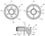
図1は本発明の第1の実施の形態に係るLED照明装置を示すもので、(a)はその正面図、(b)はその側面図、図2はその縦断側面図、図3は第1の実施例に係るLED照明装置の放熱ベースを示すもので、(a)はLED基板を取り付けた状態の放熱ベースの平面図、(b)はその背面図、(c)は放熱ベースの一部切欠正面図である。Hereinafter, embodiments of the present invention will be described with reference to the drawings.
FIG. 1 shows an LED lighting device according to a first embodiment of the present invention, in which (a) is a front view thereof, (b) is a side view thereof, FIG. 2 is a longitudinal side view thereof, and FIG. 1 shows a heat dissipation base of an LED lighting device according to one embodiment, wherein (a) is a plan view of the heat dissipation base with an LED substrate attached, (b) is a rear view thereof, and (c) is one of the heat dissipation bases. It is a part notch front view.
第1の実施の形態に係るLED照明装置は、LEDおよびその放熱手段を備えた発光部1と、商用電源からLEDに供給する電流を生成する電源部2とからなり、発光部1と電源部2とが、外気対流のための空気流通部3によって熱的に分離されている。発光部1は、図2に示すように、アルミニウム合金からなる放熱ベース10を備え、基本形は、中央部に穴11を有する環状体である。放熱ベース10は、穴11の中心軸と直交する一つの面(正面)に、複数のLEDチップ16を環状に実装したLED基板17を取り付ける基板取付面12を有している。そして、放熱ベース10の外周面と穴11の内周面に、それぞれフィン13,14が、一体に形成されている。放熱ベース10の背面には、空気流通部3を形成するための脚部15が、本例では4個、放射状に設けられている。 The LED lighting device according to the first embodiment includes a
放熱ベース10の正面には、LED基板17に搭載された複数個(本例では6個)のLEDチップ16から放射される光を面状に拡散させて放射させる乳白色の透光性カバー18が被せられている。 On the front surface of the
電源部2は、商用電源(100V)の照明器具のソケットにねじ込むねじ込み形口金21と、このねじ込み形口金21に対して絶縁されている受金22と、ねじ込み形口金21に基端部が接着固定されているプラスチック等の絶縁材料からなるケース23と、ケース23内にねじや接着剤で固定される電源基板24と、ケース23の上部開口を塞ぐとともに放熱ベース10の脚部15が固定される蓋板25を備えている。本例では、脚部15の先端に設けた固定片15aを蓋板25に設けた孔に挿入し、固定片15aの突出した部分を折り曲げるか捻ることにより、放熱ベース10を蓋板25に固定しているが、ねじ止めその他の固定方法で固定してもよい。 The
ねじ込み形21と受金22には、ケース23の内部においてリード線26,27の基端が半田等で接続されており、先端は電源基板24の端子に接続されている。また、電源基板24に搭載された電気(電子)部品によってAC100Vから直流の定電流に変換された電力は、リード線28により、放熱ベース10の基板取付面12に取り付けられたLED基板17に導かれ、LEDチップ16に所定の電流が供給される。 In the
なお、蓋板25と放熱ベース10には、リード線28を通す穴が設けられている。蓋板25には、ケース23内の空気の放熱のための孔を設けることもできるが、孔を設ける場合、孔の位置や大きさが、感電などの安全基準を満たすように設計する。 The
以上の第1の実施の形態において、白熱電球と同じ型のソケットにねじ込み形21を差し込むと、ねじ込み形21と受金22から交流100Vの電圧がリード線26,27を通って電源基板24の回路に供給される。この電源基板24に搭載された抵抗器、ダイオード、ツェナーダイオード、トランジスタ等の電気(電子)部品により、所定電圧の直流が生成され、リード線28を通してLED基板17に所定の電流が供給される。 In the first embodiment described above, when the
電源基板24に搭載された抵抗器や半導体部品からの発熱は、ケース23内の空気の温度を上昇させるが、ケース23の表面により冷却される。一方、LED基板17に搭載された複数のLEDチップ16の発光時に発生する熱は、放熱ベース10に伝達され、外周のフィン13と、穴11の内周のフィン14と、脚部15から外部に放熱される。フィン13,14および脚部15の表面に接触して加熱された空気は、比重が小さくなって上昇し、温度が低い空気と入れ替わる対流を起こす。このとき、LED照明装置の使用時の向きによっては、フィン13,14に接触した空気の対流を妨げる位置に設けられたフィンは冷却効率が低いが、各フィン13,14,脚部15は異なった位置と方向に設けられているため、いずれかのフィンないし脚部が、冷却効率の向上に寄与することになり、全体として放熱効果が向上することになる。 Heat generated from resistors and semiconductor components mounted on the
さらに、電源部2の発熱は、脚部15により発光部1とは分離されており、脚部15の隙間が空気流通部3となるので、電源部2の発熱の影響がなく、放熱ベース10の放熱設計のみを考慮すればよく、設計が容易となる。 Further, the heat generated by the
図4は本発明の第2の実施の形態に係るLED照明装置を示すもので、(a)はその正面図、(b)はその側面図である。 4A and 4B show an LED lighting device according to a second embodiment of the present invention, in which FIG. 4A is a front view thereof and FIG. 4B is a side view thereof.
図4に示すように、第2の実施の形態に係るLED照明装置は、LEDおよびその放熱手段を備えた発光部1と、商用電源からLEDに供給する電流を生成する電源部2とからなり、発光部1と電源部2とが、外気対流のための空気流通部3によって熱的に分離されている。発光部1は、アルミニウム合金からなる放熱ベース30を備え、基本形は、中央部に穴31を有する環状体である。放熱ベース30の外周面と穴31の内周面に、それぞれフィン32,33が、一体に形成されている。放熱ベース30の背面には、空気流通部3を形成するための脚部34が、本例では4個、放射状に設けられている。 As shown in FIG. 4, the LED lighting device according to the second embodiment includes a
電源部2は、商用電源(100V)の照明器具のソケットにねじ込むねじ込み形口金21と、このねじ込み形口金21に対して絶縁されている受金22と、ねじ込み形口金21に基端部が接着固定されているプラスチック等の絶縁材料からなるケース35と、ケース35内にねじや接着剤で固定される電源基板36と、ケース35の上部開口を塞ぐとともに放熱ベース30の脚部34が固定される蓋板37を備えている。 The
この第2の実施の形態が第1の実施の形態と異なるところは、放熱ベース30の外周のフィン32の向きが、放熱ベース30の穴31の中心軸線に対して垂直方向に複数段形成されていることと、ケース35の形状が2段円筒状になっていることである。フィン32の向きを上記のように形成することにより、LED照明装置を横向きで使用するときに、第1の実施の形態のフィン13の向きよりも、放熱効果が向上する。 This second embodiment differs from the first embodiment in that the
その他の構成および作用については、第1の実施の形態と同様であるので、説明を省略する。 Since other configurations and operations are the same as those in the first embodiment, the description thereof is omitted.
なお、放熱ベース10の背面には、図5に示すように、多数の棒状の補助フィン19を形成して、さらに放熱特性を向上させることができる。 As shown in FIG. 5, a large number of rod-shaped
本発明は、高輝度のLEDを複数搭載しても、放熱効果が高く、長寿命化を図ることのできるLED照明装置として、好適に利用することができる。 INDUSTRIAL APPLICABILITY The present invention can be suitably used as an LED lighting device that has a high heat dissipation effect and can extend the life even when a plurality of high-brightness LEDs are mounted.
1 発光部
2 電源部
3 空気流通部
10 放熱ベース
11 穴
12 基板取付面
13,14 フィン
15 脚部
15a 固定片
16 LEDチップ
17 LED基板
18 透光性カバー
19 背面フィン
21 ねじ込み形口金
22 受金
23 ケース
24 電源基板
25 蓋板
26,27,28 リード線
30 放熱ベース
31 穴
32,33 フィン
34 脚部
35 ケース
36 電源基板
37 蓋板DESCRIPTION OF
Claims (3)
Translated fromJapanese商用電源から前記LEDに供給する電流を生成する電源部とを有し、
前記発光部と前記電源部とが、外気対流のための空気流通部によって熱的に分離されていること
を特徴とするLED照明装置。A light-emitting unit including a plurality of LEDs and heat dissipation means; and
A power supply unit that generates current to be supplied to the LED from a commercial power supply,
The LED lighting device, wherein the light emitting unit and the power source unit are thermally separated by an air circulation unit for convection of outside air.
中央部に穴を有し、その穴の周りに基板取付面を有する環状の放熱ベースと、
前記基板取付面に取り付けられ、複数のLEDチップを実装したLED基板とを有し、
前記放熱ベースの外周及び前記穴の内周に前記放熱手段としての放熱用のフィンが形成されていること
を特徴とする請求項1記載のLED照明装置。The light emitting unit
An annular heat dissipating base having a hole in the center and a board mounting surface around the hole;
An LED substrate mounted on the substrate mounting surface and mounted with a plurality of LED chips;
The LED lighting device according to claim 1, wherein fins for heat dissipation as the heat dissipation means are formed on an outer periphery of the heat dissipation base and an inner periphery of the hole.
Priority Applications (2)
| Application Number | Priority Date | Filing Date | Title |
|---|---|---|---|
| JP2006203778AJP2008034140A (en) | 2006-07-26 | 2006-07-26 | Led lighting device |
| US11/878,287US20080024067A1 (en) | 2006-07-26 | 2007-07-23 | LED lighting device |
Applications Claiming Priority (1)
| Application Number | Priority Date | Filing Date | Title |
|---|---|---|---|
| JP2006203778AJP2008034140A (en) | 2006-07-26 | 2006-07-26 | Led lighting device |
Publications (1)
| Publication Number | Publication Date |
|---|---|
| JP2008034140Atrue JP2008034140A (en) | 2008-02-14 |
Family
ID=38985474
Family Applications (1)
| Application Number | Title | Priority Date | Filing Date |
|---|---|---|---|
| JP2006203778APendingJP2008034140A (en) | 2006-07-26 | 2006-07-26 | Led lighting device |
Country Status (2)
| Country | Link |
|---|---|
| US (1) | US20080024067A1 (en) |
| JP (1) | JP2008034140A (en) |
Cited By (24)
| Publication number | Priority date | Publication date | Assignee | Title |
|---|---|---|---|---|
| JP2009037796A (en)* | 2007-07-31 | 2009-02-19 | Toshiba Lighting & Technology Corp | Light source and lighting device |
| JP2009245846A (en)* | 2008-03-31 | 2009-10-22 | Suzhou Marsleds Optoelectronics Co Ltd | Led street light |
| WO2009110683A3 (en)* | 2008-03-06 | 2009-11-12 | 화우테크놀러지주식회사 | Fan-less heat ventilation for led lighting apparatus |
| KR100940884B1 (en)* | 2008-11-17 | 2010-02-09 | 송민훈 | Heat dissipation structure of led lamp |
| KR100972415B1 (en) | 2009-08-03 | 2010-07-27 | 김성남 | An unit for heat radiation, a lighting device using led lighting module, and an street light using a lighting module in which multi led die chips intergrated |
| JP2010199049A (en)* | 2009-02-23 | 2010-09-09 | ▲緑▼點高新科技股▲分▼有限公司 | High performance light emitter |
| KR100981683B1 (en)* | 2008-07-11 | 2010-09-10 | 김진오 | LED lighting equipment |
| KR100995706B1 (en) | 2008-06-18 | 2010-11-19 | 주식회사 자온지 | Lighting fixtures |
| WO2011007977A3 (en)* | 2009-07-16 | 2011-04-28 | (주)강동테크 | Led fluorescent lamp |
| KR20110048057A (en)* | 2008-08-22 | 2011-05-09 | 오스람 게젤샤프트 미트 베쉬랭크터 하프퉁 | Lighting devices |
| WO2011078505A3 (en)* | 2009-12-24 | 2011-08-25 | 쎄딕(주) | Led module with cooling passage |
| JP2012502432A (en)* | 2008-09-08 | 2012-01-26 | インテマティックス・コーポレーション | Light emitting diode (LED) lighting device |
| JP2012022817A (en)* | 2010-07-12 | 2012-02-02 | Ushio Spex Inc | Heat radiation structure of lighting fixture |
| KR101163016B1 (en) | 2009-09-23 | 2012-07-09 | 코닌클리즈케 필립스 일렉트로닉스 엔.브이. | A lighting device |
| JP2013077470A (en)* | 2011-09-30 | 2013-04-25 | Eye Lighting Syst Corp | Lighting device |
| JP2014502780A (en)* | 2011-01-14 | 2014-02-03 | コーニンクレッカ フィリップス エヌ ヴェ | Lighting device |
| JP2014032850A (en)* | 2012-08-03 | 2014-02-20 | Mec:Kk | Led lighting device |
| WO2014134520A1 (en)* | 2013-02-28 | 2014-09-04 | Flextronics Ap, Llc | Led back end assembly and method of manufacturing |
| US8858016B2 (en) | 2012-12-06 | 2014-10-14 | Relume Technologies, Inc. | LED heat sink apparatus |
| JP2015162395A (en)* | 2014-02-28 | 2015-09-07 | 日立アプライアンス株式会社 | Bulb type lighting device |
| JP2016012514A (en)* | 2014-06-30 | 2016-01-21 | 株式会社ケイ・シー・エス | Led lighting fixture |
| KR101825177B1 (en)* | 2011-01-18 | 2018-02-02 | 김덕용 | LED lighting device |
| KR101936045B1 (en) | 2009-06-24 | 2019-01-08 | 이루미겐, 엘엘씨 | Opto-thermal solution for multi-utility solid state lighting device using conic section geometries |
| JP2020017394A (en)* | 2018-07-25 | 2020-01-30 | 京セラ株式会社 | Illuminating device and illuminating module |
Families Citing this family (60)
| Publication number | Priority date | Publication date | Assignee | Title |
|---|---|---|---|---|
| US8118447B2 (en) | 2007-12-20 | 2012-02-21 | Altair Engineering, Inc. | LED lighting apparatus with swivel connection |
| US8360599B2 (en) | 2008-05-23 | 2013-01-29 | Ilumisys, Inc. | Electric shock resistant L.E.D. based light |
| US8021008B2 (en)* | 2008-05-27 | 2011-09-20 | Abl Ip Holding Llc | Solid state lighting using quantum dots in a liquid |
| US8212469B2 (en) | 2010-02-01 | 2012-07-03 | Abl Ip Holding Llc | Lamp using solid state source and doped semiconductor nanophosphor |
| CN102175000B (en)* | 2008-07-30 | 2013-11-06 | 东芝照明技术株式会社 | Lamp and lighting equipment |
| JP5101578B2 (en)* | 2008-08-13 | 2012-12-19 | 太一節能系統股▲分▼有限公司 | Light emitting diode lighting device |
| EP2172691A1 (en)* | 2008-10-06 | 2010-04-07 | Avex-SG Technology Inc. | Illuminating device for tools |
| KR100901180B1 (en)* | 2008-10-13 | 2009-06-04 | 현대통신 주식회사 | Heat dissipation member with variable heat dissipation path and LED emitting lamp |
| KR100903192B1 (en)* | 2008-10-17 | 2009-06-17 | 현대통신 주식회사 | LED light emitting lamp with double heat sink structure using nano spreader |
| US8653984B2 (en) | 2008-10-24 | 2014-02-18 | Ilumisys, Inc. | Integration of LED lighting control with emergency notification systems |
| US8901823B2 (en) | 2008-10-24 | 2014-12-02 | Ilumisys, Inc. | Light and light sensor |
| US7938562B2 (en) | 2008-10-24 | 2011-05-10 | Altair Engineering, Inc. | Lighting including integral communication apparatus |
| US8324817B2 (en) | 2008-10-24 | 2012-12-04 | Ilumisys, Inc. | Light and light sensor |
| KR100902631B1 (en)* | 2008-10-24 | 2009-06-12 | 현대통신 주식회사 | LED light emitting lamp of circular structure using nanospreader |
| US8214084B2 (en) | 2008-10-24 | 2012-07-03 | Ilumisys, Inc. | Integration of LED lighting with building controls |
| KR100905502B1 (en)* | 2008-11-10 | 2009-07-01 | 현대통신 주식회사 | Led lighting device |
| GB2466789A (en)* | 2009-01-05 | 2010-07-14 | Greengage Lighting Ltd | a light emitting diode lamp with heat dissipating wall |
| US8664880B2 (en) | 2009-01-21 | 2014-03-04 | Ilumisys, Inc. | Ballast/line detection circuit for fluorescent replacement lamps |
| US8330381B2 (en)* | 2009-05-14 | 2012-12-11 | Ilumisys, Inc. | Electronic circuit for DC conversion of fluorescent lighting ballast |
| US8299695B2 (en)* | 2009-06-02 | 2012-10-30 | Ilumisys, Inc. | Screw-in LED bulb comprising a base having outwardly projecting nodes |
| CN101713529A (en)* | 2009-07-23 | 2010-05-26 | 秦彪 | LED lampwick and LED illuminating lamp thereof |
| US20110110095A1 (en)* | 2009-10-09 | 2011-05-12 | Intematix Corporation | Solid-state lamps with passive cooling |
| TWI421442B (en)* | 2009-11-12 | 2014-01-01 | I Chiun Precision Ind Co Ltd | Lighting device |
| RU2418345C1 (en)* | 2009-12-31 | 2011-05-10 | Купеев Осман Геннадьевич | Light-emitting diode lamp |
| US9719012B2 (en)* | 2010-02-01 | 2017-08-01 | Abl Ip Holding Llc | Tubular lighting products using solid state source and semiconductor nanophosphor, E.G. for florescent tube replacement |
| US8517550B2 (en) | 2010-02-15 | 2013-08-27 | Abl Ip Holding Llc | Phosphor-centric control of color of light |
| CA2792940A1 (en) | 2010-03-26 | 2011-09-19 | Ilumisys, Inc. | Led light with thermoelectric generator |
| CA2794512A1 (en) | 2010-03-26 | 2011-09-29 | David L. Simon | Led light tube with dual sided light distribution |
| US8540401B2 (en)* | 2010-03-26 | 2013-09-24 | Ilumisys, Inc. | LED bulb with internal heat dissipating structures |
| DE102010003680A1 (en)* | 2010-04-07 | 2011-10-13 | Osram Gesellschaft mit beschränkter Haftung | Semiconductor lamp |
| KR101073927B1 (en)* | 2010-06-23 | 2011-10-17 | 엘지전자 주식회사 | Lighting equipment |
| US8454193B2 (en) | 2010-07-08 | 2013-06-04 | Ilumisys, Inc. | Independent modules for LED fluorescent light tube replacement |
| CA2803267A1 (en) | 2010-07-12 | 2012-01-19 | Ilumisys, Inc. | Circuit board mount for led light tube |
| EP2413015B1 (en)* | 2010-07-27 | 2015-07-01 | Cirocomm Technology Corp. | LED lamp with replaceable light unit |
| DE102010034664B4 (en)* | 2010-08-18 | 2018-06-14 | Osram Opto Semiconductors Gmbh | light source |
| CN101956921A (en)* | 2010-10-08 | 2011-01-26 | 朱小龙 | LED lamp of bionic honeycomb-shaped heat radiator |
| TW201217692A (en)* | 2010-10-21 | 2012-05-01 | Heng-Yang Fu | the heat dissipating bumps are designed with different heights to facilitate air convection around the heat dissipating bumps, improve the heat dissipating efficiency and increase the light emitting efficiency and the service time of the LED bulb |
| EP2633227B1 (en) | 2010-10-29 | 2018-08-29 | iLumisys, Inc. | Mechanisms for reducing risk of shock during installation of light tube |
| US8870415B2 (en) | 2010-12-09 | 2014-10-28 | Ilumisys, Inc. | LED fluorescent tube replacement light with reduced shock hazard |
| CN103314257B (en)* | 2011-01-14 | 2017-04-26 | 飞利浦照明控股有限公司 | Lighting device |
| US9339146B2 (en) | 2011-04-14 | 2016-05-17 | Prince Castle LLC | Universal food holding cabinet with buttoned-in escutcheons |
| CN102818134B (en)* | 2011-06-10 | 2015-02-18 | 富瑞精密组件(昆山)有限公司 | Lamp |
| US9072171B2 (en) | 2011-08-24 | 2015-06-30 | Ilumisys, Inc. | Circuit board mount for LED light |
| CN102353028A (en)* | 2011-09-19 | 2012-02-15 | 丁春辉 | Upper heat dissipation seat of integrated high-frequency electrodeless lamp and integrated high-frequency electrodeless lamp |
| US20130088848A1 (en) | 2011-10-06 | 2013-04-11 | Intematix Corporation | Solid-state lamps with improved radial emission and thermal performance |
| US8992051B2 (en) | 2011-10-06 | 2015-03-31 | Intematix Corporation | Solid-state lamps with improved radial emission and thermal performance |
| US20130176723A1 (en)* | 2011-10-06 | 2013-07-11 | Intematix Corporation | Solid-state lamps with improved radial emission and thermal performance |
| JP6191141B2 (en)* | 2012-01-26 | 2017-09-06 | Apsジャパン株式会社 | Lighting device |
| US9184518B2 (en) | 2012-03-02 | 2015-11-10 | Ilumisys, Inc. | Electrical connector header for an LED-based light |
| US9163794B2 (en) | 2012-07-06 | 2015-10-20 | Ilumisys, Inc. | Power supply assembly for LED-based light tube |
| US9271367B2 (en) | 2012-07-09 | 2016-02-23 | Ilumisys, Inc. | System and method for controlling operation of an LED-based light |
| US9285084B2 (en) | 2013-03-14 | 2016-03-15 | Ilumisys, Inc. | Diffusers for LED-based lights |
| ES2512315B1 (en)* | 2013-04-23 | 2015-07-28 | Pascual MERINO DE LA ROSA | Aluminum heat sink, for multiform mounting, high power LED |
| JP2015060740A (en)* | 2013-09-19 | 2015-03-30 | 株式会社東芝 | Lighting device |
| US9267650B2 (en) | 2013-10-09 | 2016-02-23 | Ilumisys, Inc. | Lens for an LED-based light |
| CN106063381A (en) | 2014-01-22 | 2016-10-26 | 伊卢米斯公司 | LED-based light with addressed LEDs |
| US9759387B2 (en)* | 2014-03-04 | 2017-09-12 | Cree, Inc. | Dual optical interface LED lamp |
| US9510400B2 (en) | 2014-05-13 | 2016-11-29 | Ilumisys, Inc. | User input systems for an LED-based light |
| US9664343B2 (en)* | 2014-12-18 | 2017-05-30 | GE Lighting Solutions, LLC | Unitary heat sink for solid state lamp |
| US10161568B2 (en) | 2015-06-01 | 2018-12-25 | Ilumisys, Inc. | LED-based light with canted outer walls |
Family Cites Families (1)
| Publication number | Priority date | Publication date | Assignee | Title |
|---|---|---|---|---|
| US6791283B2 (en)* | 2001-09-07 | 2004-09-14 | Opalec | Dual mode regulated light-emitting diode module for flashlights |
- 2006
- 2006-07-26JPJP2006203778Apatent/JP2008034140A/enactivePending
- 2007
- 2007-07-23USUS11/878,287patent/US20080024067A1/ennot_activeAbandoned
Cited By (25)
| Publication number | Priority date | Publication date | Assignee | Title |
|---|---|---|---|---|
| JP2009037796A (en)* | 2007-07-31 | 2009-02-19 | Toshiba Lighting & Technology Corp | Light source and lighting device |
| WO2009110683A3 (en)* | 2008-03-06 | 2009-11-12 | 화우테크놀러지주식회사 | Fan-less heat ventilation for led lighting apparatus |
| JP2009245846A (en)* | 2008-03-31 | 2009-10-22 | Suzhou Marsleds Optoelectronics Co Ltd | Led street light |
| KR100995706B1 (en) | 2008-06-18 | 2010-11-19 | 주식회사 자온지 | Lighting fixtures |
| KR100981683B1 (en)* | 2008-07-11 | 2010-09-10 | 김진오 | LED lighting equipment |
| KR20110048057A (en)* | 2008-08-22 | 2011-05-09 | 오스람 게젤샤프트 미트 베쉬랭크터 하프퉁 | Lighting devices |
| KR101651527B1 (en) | 2008-08-22 | 2016-08-26 | 오스람 게엠베하 | Lighting device |
| JP2012502432A (en)* | 2008-09-08 | 2012-01-26 | インテマティックス・コーポレーション | Light emitting diode (LED) lighting device |
| KR100940884B1 (en)* | 2008-11-17 | 2010-02-09 | 송민훈 | Heat dissipation structure of led lamp |
| JP2010199049A (en)* | 2009-02-23 | 2010-09-09 | ▲緑▼點高新科技股▲分▼有限公司 | High performance light emitter |
| KR101936045B1 (en) | 2009-06-24 | 2019-01-08 | 이루미겐, 엘엘씨 | Opto-thermal solution for multi-utility solid state lighting device using conic section geometries |
| WO2011007977A3 (en)* | 2009-07-16 | 2011-04-28 | (주)강동테크 | Led fluorescent lamp |
| KR100972415B1 (en) | 2009-08-03 | 2010-07-27 | 김성남 | An unit for heat radiation, a lighting device using led lighting module, and an street light using a lighting module in which multi led die chips intergrated |
| KR101163016B1 (en) | 2009-09-23 | 2012-07-09 | 코닌클리즈케 필립스 일렉트로닉스 엔.브이. | A lighting device |
| WO2011078505A3 (en)* | 2009-12-24 | 2011-08-25 | 쎄딕(주) | Led module with cooling passage |
| JP2012022817A (en)* | 2010-07-12 | 2012-02-02 | Ushio Spex Inc | Heat radiation structure of lighting fixture |
| JP2014502780A (en)* | 2011-01-14 | 2014-02-03 | コーニンクレッカ フィリップス エヌ ヴェ | Lighting device |
| KR101825177B1 (en)* | 2011-01-18 | 2018-02-02 | 김덕용 | LED lighting device |
| JP2013077470A (en)* | 2011-09-30 | 2013-04-25 | Eye Lighting Syst Corp | Lighting device |
| JP2014032850A (en)* | 2012-08-03 | 2014-02-20 | Mec:Kk | Led lighting device |
| US8858016B2 (en) | 2012-12-06 | 2014-10-14 | Relume Technologies, Inc. | LED heat sink apparatus |
| WO2014134520A1 (en)* | 2013-02-28 | 2014-09-04 | Flextronics Ap, Llc | Led back end assembly and method of manufacturing |
| JP2015162395A (en)* | 2014-02-28 | 2015-09-07 | 日立アプライアンス株式会社 | Bulb type lighting device |
| JP2016012514A (en)* | 2014-06-30 | 2016-01-21 | 株式会社ケイ・シー・エス | Led lighting fixture |
| JP2020017394A (en)* | 2018-07-25 | 2020-01-30 | 京セラ株式会社 | Illuminating device and illuminating module |
Also Published As
| Publication number | Publication date |
|---|---|
| US20080024067A1 (en) | 2008-01-31 |
Similar Documents
| Publication | Publication Date | Title |
|---|---|---|
| JP2008034140A (en) | Led lighting device | |
| CN102032479B (en) | Bulb-shaped lamp and illuminator | |
| JP5578361B2 (en) | Lamp with lamp and lighting equipment | |
| JP5354191B2 (en) | Light bulb shaped lamp and lighting equipment | |
| CN202613097U (en) | Bulb-shaped lamp and lighting appliance | |
| US7513653B1 (en) | LED lamp having heat sink | |
| JP5327472B2 (en) | Light bulb shaped lamp and lighting equipment | |
| RU2510874C2 (en) | Radially directed heat dissipating device and pear-shaped light-emitting device using same | |
| TWI439635B (en) | Light- emitting device | |
| JP5508113B2 (en) | Lamp and lighting device | |
| JP2010135181A (en) | Illuminating device | |
| JP5427294B2 (en) | LED lamp | |
| WO2014119169A1 (en) | Led illumination device | |
| CN102308143A (en) | Lamp and illumination apparatus | |
| JP2010182796A (en) | Led lamp | |
| JP5849238B2 (en) | Lamp and lighting device | |
| WO2012008175A1 (en) | Lighting device | |
| JP5582899B2 (en) | Lamp and lighting device | |
| JP5333488B2 (en) | LED lighting device | |
| JP2010170903A (en) | Socket for light source, and lighting fixture | |
| JP2012146552A (en) | Lighting device | |
| JP2011181252A (en) | Lighting fixture | |
| JP2008252141A (en) | Led-lighting device | |
| KR101611391B1 (en) | The led light to be equipped isolation heat-discharging plate | |
| JP2015002076A (en) | Lighting device |