JP2008027121A - Remote control device - Google Patents
Remote control deviceDownload PDFInfo
- Publication number
- JP2008027121A JP2008027121AJP2006198040AJP2006198040AJP2008027121AJP 2008027121 AJP2008027121 AJP 2008027121AJP 2006198040 AJP2006198040 AJP 2006198040AJP 2006198040 AJP2006198040 AJP 2006198040AJP 2008027121 AJP2008027121 AJP 2008027121A
- Authority
- JP
- Japan
- Prior art keywords
- remote control
- body case
- main body
- control device
- movement
- Prior art date
- Legal status (The legal status is an assumption and is not a legal conclusion. Google has not performed a legal analysis and makes no representation as to the accuracy of the status listed.)
- Withdrawn
Links
- 230000033001locomotionEffects0.000claimsabstractdescription118
- 230000007246mechanismEffects0.000claimsdescription14
- 238000000034methodMethods0.000claimsdescription14
- 230000007274generation of a signal involved in cell-cell signalingEffects0.000claimsdescription13
- 239000007787solidSubstances0.000claimsdescription6
- 230000024042response to gravityEffects0.000claimsdescription4
- 230000006870functionEffects0.000description20
- 238000010586diagramMethods0.000description8
- 238000001514detection methodMethods0.000description7
- 238000004891communicationMethods0.000description5
- 230000008569processEffects0.000description5
- 230000006698inductionEffects0.000description4
- 230000003287optical effectEffects0.000description4
- 230000001133accelerationEffects0.000description3
- 238000004364calculation methodMethods0.000description3
- 239000004973liquid crystal related substanceSubstances0.000description3
- 230000002093peripheral effectEffects0.000description3
- 230000005540biological transmissionEffects0.000description2
- 230000005484gravityEffects0.000description2
- 230000004044responseEffects0.000description2
- 230000001953sensory effectEffects0.000description2
- XLYOFNOQVPJJNP-UHFFFAOYSA-NwaterSubstancesOXLYOFNOQVPJJNP-UHFFFAOYSA-N0.000description2
- 230000008859changeEffects0.000description1
- 238000006243chemical reactionMethods0.000description1
- 238000004590computer programMethods0.000description1
- 238000005034decorationMethods0.000description1
- 230000003247decreasing effectEffects0.000description1
- 239000000428dustSubstances0.000description1
- 230000000694effectsEffects0.000description1
- 230000005674electromagnetic inductionEffects0.000description1
- 238000005516engineering processMethods0.000description1
- 238000005286illuminationMethods0.000description1
- 238000010606normalizationMethods0.000description1
- 230000009967tasteless effectEffects0.000description1
Images


Landscapes
- Details Of Television Systems (AREA)
- Selective Calling Equipment (AREA)
- Position Input By Displaying (AREA)
Abstract
Translated fromJapaneseDescription
Translated fromJapanese本発明は、電子機器やその他の装置の遠隔制御に使用される遠隔制御装置に関する。 The present invention relates to a remote control device used for remote control of electronic equipment and other devices.
電子機器の制御をコードレスで行うために、リモートコントローラが使用される。例えば、パーソナルコンピュータでは、ディスプレイに表示されるカーソルの操作をコードレスで行うためのワイヤレスマウスが知られている(特許文献1参照)。
既知の従来の技術には、次のような解決すべき課題があった。
電子機器の多機能化により、その制御内容が複雑になり、リモートコントローラにも多数のボタンが設けられるようになった。その操作は複雑で煩わしい。また、日や指の不自由な人や子供には操作が困難なものも多い。本発明はこうした課題を解決するためになされたものである。本発明は、比較的単純な操作により制御対象機器の遠隔制御ができ、外観や操作感のよい遠隔制御装置を提供することを目的とする。The known prior art has the following problems to be solved.
With the increased functionality of electronic devices, the details of the control have become complex, and a large number of buttons have been provided on the remote controller. The operation is complicated and troublesome. In addition, there are many things that are difficult for people and children who have difficulty with the day and fingers. The present invention has been made to solve these problems. SUMMARY OF THE INVENTION An object of the present invention is to provide a remote control device that can remotely control a device to be controlled by a relatively simple operation and has a good appearance and operational feeling.
以下の構成は上記の課題を解決するための手段である。
〈構成1〉 本体ケースと、上記本体ケースの内部に収容され、当該本体ケースが回転運動もしくは移動運動をしたとき、上記運動を検出する運動状態センサと、上記運動状態センサの出力から、上記本体ケースの回転量もしくは移動量を取得する運動量取得手段と、制御対象機器の制御の種類と制御量を、上記本体ケースの回転量もしくは移動量と対応付けた、対応制御データを記憶した記憶装置と、上記運動量取得手段の取得した上記本体ケースの回転量もしくは移動量に対応する上記制御対象機器の制御の種類と制御量を含む遠隔制御信号を、上記記憶装置に記憶された対応制御データを参照して生成する遠隔制御信号生成手段と、上記遠隔制御信号生成手段の生成した遠隔制御信号を無線送信する送信機とを備えたことを特徴とする遠隔制御装置。The following configuration is means for solving the above problems.
<
制御対象機器は遠隔制御の可能な任意の機器で構わない。特にテレビジョン受像機やDVDレコーダ等の家庭用電子機器への利用が適する。全体として密閉構造で操作ボタン等のない単純な形状のものにすることもできる。回転動作や移動動作により様々な機器の様々な遠隔制御が可能になる。さらに、操作説明を表示した面を上にして回したり、前後左右に動かしたり、あるいは卓上を叩いたり、今までのリモコンとは異なるユニークな操作感が生み出される。従って、感覚的な魅力度の高い商品を提供できる。 The device to be controlled may be any device that can be controlled remotely. In particular, it is suitable for use in household electronic devices such as television receivers and DVD recorders. As a whole, it can be a simple structure with a closed structure and no operation buttons. Various remote control of various devices becomes possible by rotating operation and moving operation. In addition, you can turn the display with the operation description up, move it back and forth, right and left, or hit the tabletop, creating a unique feeling of operation that is different from previous remote controls. Therefore, it is possible to provide a product with a high sensory appeal.
〈構成2〉 構成1に記載の遠隔制御装置において、上記本体ケースの、特定の線分に沿って移動する運動、もしくは、特定の軸を中心に回転する運動、もしくは、特定の面上を移動する運動のうちのいずれかを許容するガイド機構を設けたことを特徴とする遠隔制御装置。 <Configuration 2> In the remote control device according to
本体ケースの運動方向を、一次元方向、即ち、特定の線分に沿って移動する運動だけに制限することができる。また、自転、即ち、特定の軸を中心に回転する運動だけに制限することができる。さらに、二次元方向、即ち、特定の面上を移動する運動だけに制限することができる。回転と軸方向の移動というように、特定の運動を組み合わせたものに制限してもよい。一次元方向、二次元方向、自転運動に制限すると、2軸制御あるいは一軸制御でよいため、十分にゆるやかな精度で運動を検出できる。ガイド機構は、本体ケースと嵌り合う棒状のもの、レール状のもの、ワイヤ状のもの等、任意のものが利用できる。ガイド機構は複数を組み合わせてもよい。 The movement direction of the main body case can be limited to a one-dimensional direction, that is, a movement that moves along a specific line segment. Further, the rotation can be limited only to the rotation, that is, the movement rotating around a specific axis. Furthermore, it can be limited to a two-dimensional direction, i.e., a movement that moves on a specific surface. It may be limited to a combination of specific movements such as rotation and axial movement. If limited to one-dimensional direction, two-dimensional direction, and rotation, two-axis control or single-axis control may be used, and therefore the motion can be detected with sufficiently moderate accuracy. As the guide mechanism, an arbitrary one such as a rod-like one that fits into the main body case, a rail-like one, or a wire-like one can be used. A plurality of guide mechanisms may be combined.
〈構成3〉 構成2に記載の遠隔制御装置において、上記本体ケースは、平坦な操作台上でこの操作台に接する基準面を有し、上記運動状態センサは、上記本体ケースの内部に収容され、当該本体ケースが上記基準面を上記操作台に接触させた状態で回転運動もしくは移動運動をしたとき、上記運動を検出することを特徴とする遠隔制御装置。 <Configuration 3> In the remote control device according to Configuration 2, the main body case has a reference surface in contact with the operation table on a flat operation table, and the motion state sensor is accommodated in the main body case. The remote control device detects the movement when the main body case makes a rotational movement or a movement movement with the reference surface in contact with the operation table.
平坦な操作台上で操作すると、2軸制御でよいため、比較的ゆるやかな精度で運動を検出できる。なお、操作台は遠隔制御装置の移動範囲だけほぼ平坦ならばよく、その平坦面の周辺部分は平坦でなくて構わない。平坦な操作台上で簡単に操作できるから、手や指先の運動が不自由な人にも操作できる。 When operated on a flat operation table, since two-axis control is sufficient, motion can be detected with relatively moderate accuracy. It should be noted that the operation table only needs to be substantially flat within the moving range of the remote control device, and the peripheral portion of the flat surface may not be flat. Because it can be easily operated on a flat operation table, it can also be operated by people with limited hand and fingertip movement.
〈構成4〉 構成3に記載の遠隔制御装置において、上記本体ケースは複数の面を持つ立体であって、上記平坦な操作台に接触させた面を上記基準面とし、上記運動状態センサは、上記基準面が別の面に切り替えられたことを検出し、上記遠隔制御信号生成手段は、上記基準面とされた面に割り付けられた制御対象機器の制御の種類もしくは制御量を示す信号を、遠隔制御信号とすることを特徴とする遠隔制御装置。 <Configuration 4> In the remote control device according to Configuration 3, the main body case is a solid body having a plurality of surfaces, the surface in contact with the flat operation table is the reference surface, and the motion state sensor is Detecting that the reference surface has been switched to another surface, the remote control signal generating means, a signal indicating the type or amount of control of the control target device assigned to the surface that is the reference surface, A remote control device characterized in that it is a remote control signal.
本体ケースに複数の面があるとき、各面が基準面とされた場合に対応する制御対象機器の制御の種類もしくは制御量を決めておく。例えば、ある面を基準面に切り替えたときには、制御対象機器の電源をオフにする。これにより、面毎に見ると単機能でも、各種の複雑な制御ができる。 When the main body case has a plurality of surfaces, the type or amount of control of the control target device corresponding to each surface being a reference surface is determined. For example, when a certain surface is switched to the reference surface, the control target device is turned off. Thereby, various complicated controls can be performed even with a single function when viewed on a surface-by-surface basis.
〈構成5〉 構成3又は4に記載の遠隔制御装置において、上記運動状態センサは、重力に反応して動作するスイッチ素子を含み、水平な面であって下側に面した面を上記基準面とされた面と判定する基準面検出手段を備えたことを特徴とする遠隔制御装置。 <Configuration 5> In the remote control device according to Configuration 3 or 4, the motion state sensor includes a switch element that operates in response to gravity, and a surface that is a horizontal surface and faces downward is referred to as the reference surface. A remote control device comprising reference surface detection means for determining a determined surface.
平坦な操作台は机等の水平な面であることが好ましい。基準面とされた面が切り替えられたときにこれを検出しなければならない。これに、重力に反応して動作するスイッチ素子を使用することができる。このスイッチ素子は例えば、キャビティに収容された可動ボールと装置の各面に対応させて設けた光スイッチにより構成できる。可動ボールは重力により常にキャビティの最下部に静止する。この可動ボールを検出した光スイッチが基準面とされた面を検出する。 The flat operation table is preferably a horizontal surface such as a desk. This must be detected when the reference plane is switched. For this, a switch element that operates in response to gravity can be used. This switch element can be constituted by, for example, a movable ball accommodated in a cavity and an optical switch provided corresponding to each surface of the apparatus. The movable ball always stops at the bottom of the cavity due to gravity. The optical switch that detects the movable ball detects the surface that is the reference surface.
〈構成6〉 構成3乃至5のいずれかに記載の遠隔制御装置において、上記本体ケースは多面体であって、ある面が基準面とされたときに操作できる操作説明を、上記基準面と異なる面に表示したことを特徴とする遠隔制御装置。 <Configuration 6> In the remote control device according to any one of configurations 3 to 5, the main body case is a polyhedron, and an operation description that can be operated when a certain surface is set as a reference surface is a surface different from the reference surface. Remote control device characterized by being displayed on the screen.
本体ケースの基準面が下側になったとき、他のいずれかの面を見ながら操作できるように、基準面と異なる面に操作説明を表示した。操作説明の内容は、文字でも図解でも構わない。 When the reference surface of the main body case is on the lower side, the operation explanation is displayed on a different surface from the reference surface so that it can be operated while looking at any other surface. The contents of the operation explanation may be text or illustration.
〈構成7〉 構成6に記載の遠隔制御装置において、上記本体ケースは多面体であって、ある面が基準面とされたときに操作する操作方向を含む操作説明を、上記基準面とほぼ平行な面であって、基準面の反対側に位置する面に表示したことを特徴とする遠隔制御装置。 <Configuration 7> In the remote control device according to Configuration 6, the main body case is a polyhedron, and an operation description including an operation direction operated when a certain surface is set as a reference surface is substantially parallel to the reference surface. A remote control device characterized in that the remote control device is displayed on a surface located on the opposite side of the reference surface.
本体ケースの基準面とされた面は平坦な操作台に接触している。本体ケースは平坦な操作台上で運動させる。基準面の反対側にあるほぼ平行な面に表示された操作説明中に矢印等の操作方向が表示される。説明中の操作方向が本体ケースの実際の移動方向と一致しているので、操作感がよい。また、自然に、基準面を操作台に接触させて操作するように誘導できる。 The reference surface of the main body case is in contact with a flat operation table. The body case is moved on a flat operation table. The operation direction such as an arrow is displayed during the operation explanation displayed on the substantially parallel surface on the opposite side of the reference surface. Since the operation direction in the description matches the actual movement direction of the main body case, the operation feeling is good. Moreover, it can guide | induce so that a reference plane may be contacted with an operation console naturally and operated.
〈構成8〉 構成1乃至7のいずれかに記載の遠隔制御装置において、上記本体ケースは、外壁に可動部分のない密閉構造の立体から構成されることを特徴とする遠隔制御装置。 <
外壁に可動部分のない密閉構造にすることにより、水塗れ等に強く機械的な強度も高くすることができる。 By adopting a sealed structure with no movable parts on the outer wall, it is strong against water smearing and the like, and the mechanical strength can be increased.
〈構成9〉 構成1乃至8のいずれかに記載の遠隔制御装置において、遠隔制御のための動作パラメータを設定する動作設定手段と、上記動作パラメータを送受信するための無線送受信機を備えたことを特徴とする遠隔制御装置。 <Configuration 9> In the remote control device according to any one of
動作条件の設定や調整が必要なとき、密閉構造ではインタフェースケーブルの接続ができない。従って、遠隔制御のための動作パラメータを設定する動作設定手段を設け、動作パラメータを送受信するための無線送受信機を設けた。遠隔制御のための動作パラメータは、例えば、移動量が1cmのとき、カーソルの制御量、即ち、カーソルの画面上の移動距離をどれだけにするかといったデータである。無線通信には、遠隔制御信号を送信する送信機を兼用してもよいし、全く別の無線送受信機を設けてもよい。駆動用電池の充電も、接続端子を使用することがないコードレス方式が好ましい。即ち、誘導コイルをトランスの二次コイルにして、充電器に設けた一次コイルから電力の供給を受けて充電するとよい。 When operating conditions need to be set or adjusted, the interface cable cannot be connected in a sealed structure. Therefore, an operation setting means for setting operation parameters for remote control is provided, and a wireless transceiver for transmitting and receiving operation parameters is provided. The operation parameter for remote control is, for example, data indicating how much the cursor control amount, that is, how much the cursor moves on the screen when the movement amount is 1 cm. For wireless communication, a transmitter that transmits a remote control signal may be used, or a completely different wireless transceiver may be provided. A cordless system that does not use a connection terminal is also preferable for charging the driving battery. In other words, the induction coil is used as a secondary coil of the transformer, and charging is performed by receiving power from a primary coil provided in the charger.
〈構成10〉 構成1乃至9のいずれかに記載の遠隔制御装置において、上記操作方法を表示する面に、画像表示体を設けたことを特徴とする遠隔制御装置。 <
画像表示体は例えば液晶ディスプレイや電子ペーパーが適する。こうした画像表示体を本体ケースのいずれかの面に一体化しておくと、操作方法を表示するだけでなく、装置の状態や制御状態をモジュールや図形で表示することができる。 For example, a liquid crystal display or electronic paper is suitable for the image display. If such an image display body is integrated on either surface of the main body case, not only the operation method can be displayed, but also the state and control state of the apparatus can be displayed in modules and graphics.
〈構成11〉 構成1乃至10のいずれかに記載の遠隔制御装置において、複数の別個独立した上記本体ケースを有し、上記各本体ケースには、それぞれ、上記運動状態センサと上記運動量取得手段と上記記憶装置と上記遠隔制御信号生成手段と上記送信機とを設け、上記制御対象機器の制御を上記各本体ケースが分担していることを特徴とする遠隔制御装置。 <
一つの遠隔制御装置に多種多様な機能が含まれていると、利用者の不注意等による誤操作率が高まる。また、老人や子供が簡単に操作することが難しくなる。そこで、例えば、単機能の本体ケースを複数設ける。また、あるいは、全ての機能を持つ本体ケースの他に、費用頻度の高い操作のみができる本体ケースを設ける。例えば、テレビジョンのチャンネル選択のみを可能にする本体ケースを設けるとよい。老人や子供は、専ら単機能の本体ケースを操作すればよい。なお、各本体ケースには、全ての機能を実現できるセンサやモジュールを収納しておき、各本体ケースのパラメータの設定をそれぞれ独自にすることで、別々の動作をさせてもよい。 If various functions are included in one remote control device, the erroneous operation rate due to carelessness of the user increases. In addition, it becomes difficult for the elderly and children to easily operate. Therefore, for example, a plurality of single-function main body cases are provided. Alternatively, in addition to the main body case having all functions, a main body case capable of performing only expensive operations is provided. For example, a main body case that enables only television channel selection may be provided. Elderly people and children only need to operate a single-function main unit case. In addition, each main body case may store sensors and modules capable of realizing all functions, and each parameter setting of each main body case may be independently set to perform different operations.
本発明の遠隔制御装置は、基本的にボタン操作が不要で、装置本体を移動させたり、回転させたりといった動きによって、各種の遠隔制御信号を生成して送信する。専用のボタンを操作する既存の遠隔制御装置とは全く異なる使用方法になる。以下、本発明の実施の形態を実施例毎に詳細に説明する。 The remote control device of the present invention basically requires no button operation, and generates and transmits various remote control signals by movements such as moving or rotating the device body. This method is completely different from existing remote control devices that operate dedicated buttons. Hereinafter, embodiments of the present invention will be described in detail for each example.
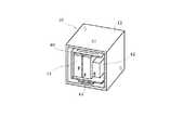
図1は、実施例1の遠隔制御装置10と操作台24を示す斜視図である。
この遠隔制御装置10は、例えば、コードやボタンのない立方体の本体ケース12に収容されている。既知の遠隔制御装置のようにボタンを操作するのでなく、本体ケース12を平坦な操作台24上で運動させることにより、該当する遠隔制御信号38を送信させる。本体ケース12の回転運動や移動運動により、特定の遠隔制御信号38を送信する。本体ケース12はこの平坦な操作台24上で、この操作台24に接する基準面26を有するものであればよい。従って、基準面26以外は曲面や凹凸のある装飾面であっても構わない。また、立方体以外の多面体であっても構わない。平坦な操作台24とは、例えば、テーブルの上面や壁面である。垂直でも水平でも傾斜していても構わない。制御対象機器はこの図の例ではパーソナルコンピュータ13である。そのディスプレイに、カーソル15が表示されている。この図の実施例では、遠隔制御装置10はこのカーソル15の移動を制御するマウスである。FIG. 1 is a perspective view illustrating the
The
図2は、実施例1の遠隔制御装置10の蓋を取った状態を示す斜視図である。
遠隔制御装置10の本体ケース12内には、運動状態センサ14と制御回路基板40と電池42とアンテナ43と充電用の誘導コイル44等が収容されている。制御回路基板40には、記憶素子やCPU等の集積回路チップが搭載されている。運動状態センサ14は本体ケース12の内部に収容されていて、本体ケース12の運動を検出する機能を有するものであればよい。運動状態センサ14は、例えば、ジャイロセンサ、加速度センサ、地磁気センサというように、回転方向、運動方向、加速度等を定量的に検出するセンサが適する。本体ケース12が基準面26を操作台24に接触させた状態で回転運動もしくは移動運動をしたときの運動を検出する。回転運動と移動運動の一方もしくは両方を検出するとよい。即ち、この遠隔制御装置10は、回転運動又は移動運動だけで遠隔制御をすることができる。また、回転運動と移動運動の組み合わせで複雑な遠隔制御をすることもできる。FIG. 2 is a perspective view illustrating a state where the lid of the
In the
ジャイロセンサ、加速度センサ、地磁気センサといった既知の運動状態センサ14は、1軸、2軸、3軸というように、用途に応じて1次元から3次元空間までの運動を検出できる。ここで、3次元運動を検出する場合に比べて2次元方向の運動を検出するほうが、はるかに低い精度で検出処理ができる。装置のコストダウンができ、信頼性も向上する。本体ケース12が基準面26を操作台24に接触させた状態で操作を可能とすれば、信頼性の高い遠隔制御信号38を生成することができる。電池42は装置の駆動電力を供給する。誘導コイル44は既知の電磁誘導によりコードレスで電池42を充電するためのものである。遠隔制御装置10を充電用の図示しないクレードルに乗せておくと電池42が充電される。 A known
図3は実施例1の遠隔制御装置10の機能ブロック図である。
遠隔制御装置10は、本体ケース12(図1)の内部に、図3に示す機構を備える。この機構は、運動状態センサ14と入出力インタフェース70と運動量取得手段16と遠隔制御信号生成手段20と無線送受信機22と記憶装置18とを有する。運動状態センサ14は、本体ケース12の内部に収容されている。運動状態センサ14は、当該本体ケース12が基準面26を操作台24に接触させた状態で回転運動もしくは移動運動をしたとき、運動を検出する機能を有する。この図の例では、運動状態センサ14は回転角度センサ71と基準面検出センサ72と地磁気センサ73とを備える。FIG. 3 is a functional block diagram of the
The
運動量取得手段16は、運動状態センサ14の出力から、本体ケース12の回転量32もしくは移動量34を取得する機能を有するものである。記憶装置18は、制御対象機器の制御の種類と制御量を、本体ケース12の回転量32もしくは移動量34と対応付けた、対応制御データ36を記憶する機能を有する。対応制御データ36の具体例は後で図5を用いて説明する。遠隔制御信号生成手段20は、遠隔制御信号38を、記憶装置18に記憶された対応制御データ36を参照して生成する機能を有するものである。遠隔制御信号38は、例えば、運動量取得手段16の取得した本体ケース12の回転量32もしくは移動量34に対応する制御対象機器の制御の種類28と制御量30を含む。無線送受信機22は、遠隔制御信号生成手段20の生成した遠隔制御信号38を、制御対象機器に対して無線送信する機能を有するものである。なお、遠隔制御装置10は様々な方向に向けられて使用されることから、無線通信は無指向性の電波や赤外線等を使用することが好ましい。また、制御対象機器からの応答を受信するときは、遠隔制御信号38の送信のみの場合には、無線送信機のみでも構わない。 The exercise amount acquisition means 16 has a function of acquiring the
運動状態センサが検出をして出力する信号は瞬時値である。信号の検出時刻を含めて演算処理をすると、本体ケース12の回転量32や移動量34が得られる。運動量取得手段16は、運動状態センサ14の出力から、演算処理によって、本体ケース12の回転量32もしくは移動量34を取得する機能を持つ。取得したデータは相対的なデータでよい。例えば、直前の静止状態から現在までに右に何度回転したか、直前の静止状態から現在までに何センチ移動したかといったデータを取得すればよい。こうしたデータの取得方法は既知の技術を利用すればよく、詳述を省略する。なお、この遠隔制御装置10は制御対象機器の一切の動作を制御する機能を備えていなくても構わない。例えば、音量調整のみの機能を備えていても構わない。 The signal detected and output by the motion state sensor is an instantaneous value. When the calculation process including the signal detection time is performed, the
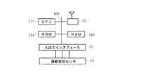
図4は実施例1の遠隔制御装置10のハードウエアブロック図である。
遠隔制御装置10はコンピュータにより制御される。図の内部バス110には、CPU(中央処理装置)111と、ROM(リードオンリメモリ)112と、RAM(ランダムアクセスメモリ)113と、入出力インタフェース70とが接続されている。CPU111はROM112に記憶されたコンピュータプログラムにより所定の処理を実行する。ROM112に、運動量取得手段16や遠隔制御信号生成手段20の動作プログラムが書き込まれる。RAM113は、記憶装置18(図2)として機能する。入出力インタフェース70には、運動状態センサ14が接続される。無線送受信機22はこの実施例ではブルートゥースによるデータ送受信方式を採用する。FIG. 4 is a hardware block diagram of the
The
図5は、対応制御データ36の実施例を示す説明図である。
遠隔制御信号生成手段20(図3)は、制御対象機器の制御の種類28と制御量30を含む遠隔制御信号38を生成する。図5に示す実施例では、遠隔制御装置10をコンピュータのマウスとして使用する例を説明する。制御の種類28は、マウスの移動、マウスの左周り、右周りといったものになる。取得データは、位置座表や角度の変化である。マウスの移動量34に対応する制御量30は、X方向やY方向にカーソルを所定の移動量だけ移動させるというものになる。マウスの移動量34をそのままコンピュータのディスプレイに表示したカーソルの制御量30と対応させる。X軸とY軸とを設定して、基準面26を含む平面をX−Y平面に設定する。このX座標とY座標からカーソルの移動量と移動方向とを演算する。コンピュータのディスプレイに表示した画面を対応するX−Y平面に設定し、マウスとカーソルの移動方向を一致させ、所定の比例係数を使用して、移動量34から制御量30を換算する。FIG. 5 is an explanatory diagram showing an example of the
The remote control signal generation means 20 (FIG. 3) generates a remote control signal 38 including the
また、本体ケース12の基準面26に垂直な回転軸を中心にした回転運動をマウスボタンのクリック操作と対応させている。例えば、本体ケース12を上記の回転軸を中心に左回転させると左クリック操作がなされたものとする。また、本体ケース12を上記の回転軸を中心に右回転させると右クリック操作がなされたものとする。また、本体ケース12を叩いたときにマウスボタンがクリックされたとしてもよい。この場合に、マウスのクリック操作が制御の種類28であり、クリックボタンのオンオフが制御量30に該当する。対応制御データ36は、いわゆる演算テーブル形式のデータで構成すればよい。 Further, the rotational movement around the rotation axis perpendicular to the
この遠隔制御装置は、テレビジョン受像機やDVDレコーダ等の家庭用電子機器への利用にも適する。そのときの遠隔制御信号38は、例えば、制御対象機器のスイッチをオンオフするといった制御信号である。スイッチのオンオフ制御は「制御の種類28」に該当する。スイッチの場合、「制御量30」はオンかオフの2種類である。例えば、音響機器の音量や照明の明るさを制御するとき、ツマミを回す角度が制御の種類28に該当する。また、音量や明るさが制御量30に該当する。制御対象機器は遠隔制御の可能な任意の機器で構わない。 This remote control device is also suitable for use in household electronic devices such as a television receiver and a DVD recorder. The remote control signal 38 at that time is, for example, a control signal for turning on / off a switch of the control target device. The on / off control of the switch corresponds to “control
遠隔制御信号38自体のデータ構成は、無線送信をし易い形式で、制御対象機器が受信をして処理をし易い任意の形式にすればよい。無線送受信機22は、遠隔制御信号38を制御対象機器に対して無線送信する機能を持つ。例えば、ブルートゥースや無線LAN(ローカルエリアネットワーク)、赤外線通信等、任意の通信技術を利用することができる。例えば、制御対象機器の応答を受信して、その内容をLED等で表示するようにしてもよい。全体として密閉構造で操作ボタン等のない単純な形状のもので、その回転動作や移動動作により様々な機器の様々な遠隔制御が可能になる。また、平坦な操作台24上で簡単に操作できるから、手や指先の運動が不自由な人にも操作できるという効果がある。さらに、操作説明を表示した面を上にして回したり、前後左右に動かしたり、あるいは卓上を叩いたり、今までのリモコンとは異なるユニークな操作感が生み出される。従って、感覚的な魅力度の高い商品を提供できる。 The data structure of the remote control signal 38 itself may be in a format that facilitates wireless transmission and any format that is easy for the device to be controlled to receive and process. The
図6は、実施例2の遠隔制御装置を示す斜視図である。図6の(a)と(b)と(c)はそれぞれ別々の例を示す。
図示の遠隔制御装置10はこれまで説明したものと同様の構成をしている。ここで図6(a)のように、L字状のガイド機構81を設ける。遠隔制御装置10をこのガイド機構81に沿わせて移動させる。遠隔制御装置10は、面の変更と矢印91方向への直線運動しかしない。また、例えば、図6(b)のように、遠隔制御装置10の周面に溝85を設ける。そして、リブ状のガイド機構82にこの溝85を嵌め合わせた状態で遠隔制御装置10を移動する。遠隔制御装置10は、溝85のある面を下にした面の変更と矢印92方向への直線運動しかしない。図6(c)では、遠隔制御装置10に貫通孔86を設けて、棒状のガイド機構83を挿通する。遠隔制御装置10は、矢印93方向の平行移動と、矢印94方向の回転運動しかしない。FIG. 6 is a perspective view illustrating the remote control device according to the second embodiment. (A), (b) and (c) of FIG. 6 show different examples.
The illustrated
上記のガイド機構は、本体ケースの、特定の線分に沿って移動する運動、もしくは、特定の軸を中心に回転する運動、もしくは、特定の面上を移動する運動のうちのいずれかのみを許容する機能を持てばよい。本体ケースの運動方向を、一次元方向、即ち、特定の線分に沿って移動する運動だけに制限する。また、自転、即ち、特定の軸を中心に回転する運動だけに制限する。さらに、二次元方向、即ち、特定の面上を移動する運動だけに制限する。一次元方向、二次元方向、自転運動に制限すると、2軸制御あるいは一軸制御でよいため、十分にゆるやかな精度で運動を検出できる。ガイド機構は、本体ケースと嵌り合う棒状のもの、レール状のもの、ワイヤ状のもの等、任意のものが利用できる。 The guide mechanism described above is only a movement of the main body case that moves along a specific line segment, a movement that rotates around a specific axis, or a movement that moves on a specific surface. It is only necessary to have an acceptable function. The movement direction of the main body case is limited to a one-dimensional direction, that is, a movement that moves along a specific line segment. Further, the rotation is limited only to the rotation, that is, the movement rotating around a specific axis. Further, the movement is limited to a two-dimensional direction, that is, a movement moving on a specific surface. If limited to one-dimensional direction, two-dimensional direction, and rotation, two-axis control or single-axis control may be used, and therefore the motion can be detected with sufficiently moderate accuracy. As the guide mechanism, an arbitrary one such as a rod-like one that fits into the main body case, a rail-like one, or a wire-like one can be used.
図1に示した例では、遠隔制御装置10の本体ケース12が平坦な操作台上でこの操作台に接する基準面を有する。本体ケース12が基準面を操作台に接触させた状態で回転運動もしくは移動運動をするので、2軸制御でよくなる。特別なガイドが不要なので、最も汎用性が高い。なお、この遠隔制御装置の移動範囲だけほぼ平坦ならばよく、その平坦面の周辺部分が平坦でなくて構わない。平坦な操作台上で簡単に操作できるから、手や指先の運動が不自由な人にも操作できる。図6のようにガイド機構を設けると、さらに手の不自由な人にも正確な操作ができる。また、デザイン化されたガイド機構は、楽しみの要素も採り入れることができる。 In the example shown in FIG. 1, the
図7は実施例3の遠隔制御装置10を示す斜視図である。
例えば、図の例は、DVD装置を制御するための遠隔制御装置10の斜視図である。本体ケース12の各面に制御が割り付けられている。図7(a)は再生、早送り、戻り等の操作説明56を表示した面である。この面の真下にある面が基準面26である。本体ケース12を左右に動かすと、再生を開始したり停止したり早送りをしたりする。図7(b)はトラック選択の操作説明56を表示した面である。動かす方向に表示したトラックを選択する。図7(c)は音量調整を表示した面である。本体ケース12を右回転すると音が大きくなり、左回転させると音が小さくなる。FIG. 7 is a perspective view illustrating the
For example, the example in the figure is a perspective view of the
本体ケース12の基準面26とされた面は平坦な操作台に接触している。本体ケース12は平坦な操作台上で持ち上げずに運動させる。従って、基準面26とされた面を見ることはできない。また、操作説明56中に矢印等の操作方向を示す表示が含まれている場合には、この表示と本体ケース12の実際の移動方向とが一致しているのが、最も操作感がよい。また、移動方向等を含む操作説明は、基準面26の反対側にある面であってこの基準面26にほぼ平行な面に表示されるとよい。利用者は自然に基準面26を下にして、操作台の上に置いて操作することになるからである。従って、実施例では操作説明56を基準面26と平行な面であって、基準面26の反対側に位置する面に表示した。この面は、平坦な操作台24上で丁度真上を向く。操作性にこだわらなければ、操作説明を基準面と異なる面に表示すればよい。即ち、本体ケースの基準面が下側になったとき、他のいずれかの面を見ながら操作できるように、基準面と異なる面に、ある面が基準面とされたときに操作できる操作説明を表示すればよい。操作説明の内容は、文字でも図解でも構わない。また、操作説明を表示した面は、基準面とほぼ平行な面が最もが望ましい。ほぼ平行というのは、厳密な平行ではない。真上から見て操作説明が明瞭に読める程度に傾斜していても差し支えない。従って、操作説明を表示した面は湾曲面であってもよい。 The surface defined as the
なお、基準面26とされる面を1面だけ持つ立体で遠隔制御装置10を構成しても構わない。このときは、立体を任意の形状に設計するとよい。例えば、人形のような形状でもよいし、その他の置物の形状でも構わない。適切な装飾を施すことにより、既存の無味乾燥な遠隔制御装置10のイメージを変えることができる。また、手や指の不自由な人の操作し易い形状にすることもできる。本体ケース12は、外壁に可動部分のない密閉構造の立体から構成されることが好ましい。外壁に可動部分のない密閉構造にすることにより、水塗れ等に強く機械的な強度も高くすることができる。スイッチや接続端子を一切持たない。多面体が最も実用的であるが、その他の任意の立体で構わない。密閉構造といっても水密性を損なわず、埃の侵入も阻止できる程度の微小な空気孔等を設けておくことは差し支えない。 Note that the
図8は実施例4の遠隔制御装置のスイッチ素子の動作説明図で、(a)は分解斜視図、(b)は合体斜視図である。
図7を用いて説明したように、平坦な操作台24に常に一定の基準面26を接触させているだけでなく、別の面を新たな基準面26に切り替えることができる。即ち、別の面を平坦な操作台24に接触させて、別の操作をする。この操作をしたとき、運動状態センサ14(図2)は、基準面26が別の面に切り替えられたことを検出する。遠隔制御信号生成手段20は、基準面26とされた面に割り付けられた制御対象機器の制御の種類28もしくは制御量30を示す信号を、遠隔制御信号38とする。即ち、本体ケース12に複数の面があるとき、各面が基準面26とされた場合に対応する制御対象機器の制御の種類28もしくは制御量30を決めておく。例えば、ある面を基準面26に切り替えたときには、制御対象機器の電源をオフにする。従って、運動状態センサ14は、どの面が基準面にされたかを正確に検出しなければならない。また、できるだけ低コストの部品で実現することが好ましい。FIGS. 8A and 8B are operation explanatory views of the switch element of the remote control device according to the fourth embodiment. FIG. 8A is an exploded perspective view, and FIG. 8B is a combined perspective view.
As described with reference to FIG. 7, not only the fixed
例えば運動状態センサ14は、図8に示すように、重力に反応して動作するスイッチ素子48を含む。スイッチ素子48は、水平な面であって下側に面した面を基準面26とされた面と判定する基準面26検出手段として動作する。平坦な操作台24は机等の水平な面であることが好ましい。基準面26とされた面が切り替えられたときにこれを検出する。このスイッチ素子48は例えば、キャビティ50に収容された可動ボール52と、装置の各面に対応させて設けた光スイッチ54により構成される。可動ボール52は重力により常にキャビティ50の最下部に静止する。図8(b)には、その状態を示した。この可動ボール52を検出した光スイッチ54が、基準面26とされた面を特定する信号を出力する。きわめて簡単で堅牢なので、ジャイロセンサ等とは別に設けるとよい。 For example, the
図9は実施例5の遠隔制御装置を示す機能ブロック図である。
この遠隔制御装置には、遠隔制御のための動作パラメータ58を設定する動作設定手段75と、動作パラメータを送受信するための無線送受信機22を設けた。動作条件の設定や調整が必要なときには、蓋を開けてケーブルを接続しても構わない。しかし、ここでは密閉構造にしたので、無線による設定を可能にした。遠隔制御のための動作パラメータ58は、例えば、移動量34が1cmのとき、カーソルの制御量30、即ち、カーソルの画面上の移動距離をどれだけにするかといったデータである。無線通信には、遠隔制御信号38を送信する無線送受信機22を兼用してもよいし、全く別の無線送受信機を設けてもよい。図2に示した駆動用電池42の充電も、接続端子を使用することがないコードレス方式が好ましい。即ち、誘導コイル44をトランスの二次コイルにして、図示しない充電器に設けた一次コイル66から電力の供給を受けて充電するとよい。FIG. 9 is a functional block diagram illustrating the remote control device according to the fifth embodiment.
This remote control device is provided with an operation setting means 75 for setting
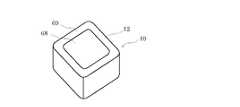
図10は実施例6の遠隔制御装置10を示す斜視図である。
この図の遠隔制御装置10の本体ケース12には、操作方法を表示する面69に、画像表示体68を設けた。画像表示体68は、例えば液晶ディスプレイや電子ペーパーが適する。こうした画像表示体68を本体ケース12のいずれかの面に一体化しておくと、操作方法を表示するだけでなく、装置の状態や制御状態をモジュールや図形で表示することができる。例えば、図6(b)に示す面に、携帯電話と同様の構成の液晶ディスプレイを取り付ける。ここに、制御対象機器から受信した情報に基づいて、例えば、DVDのコンテンツをリスト表示することもできる。全ての操作方法の表示が画像表示体68を利用して行われると、装置全体を汎用性のある構造にして、装置の内部メモリに記憶させるデータを入れ替えるだけで、あらゆる機器の遠隔制御装置として使用できる。また、装置から遠隔制御のための動作プログラムやデータのダウンロードを受ければ、同じ遠隔制御装置を多種の装置の制御に使用することもできる。FIG. 10 is a perspective view illustrating the
In the
図11は実施例7の遠隔制御装置10を示す斜視図である。
この遠隔制御装置10は、複数の別個独立した本体ケース121〜124を有する。各本体ケースには、それぞれ、運動状態センサ14と運動量取得手段16と記憶装置18と遠隔制御信号生成手段20と無線送受信機22とを設け、制御対象機器の制御を各本体ケースが分担している。一つの遠隔制御装置10に多種多様な機能が含まれていると、利用者の不注意等による誤操作をする率が高まる。また、老人や子供が簡単に操作することが難しくなる。そこで、例えば、全ての機能を持つ本体ケース121の他に、使用頻度の高い操作のみができる本体ケース122〜124を設ける。即ち、単機能の本体ケースを複数設ける。本体ケース122はテレビジョンのスイッチをオンオフする機能のみを有する。本体ケース123はテレビジョンのチャンネル選択のみを可能にする。本体ケース124はテレビジョンの音量調整のみを可能にする。老人や子供は、専ら単機能の本体ケースを操作すればよい。なお、各本体ケース121〜124には、全ての機能を実現できるセンサやモジュールを収納しておき、パラメータの設定をそれぞれ独自にすることで、別々の動作をさせるようにしてもよい。FIG. 11 is a perspective view illustrating the
The
図12は、遠隔制御装置10の全体的な動作例を示すフローチャートである。
上記の各実施例の構成を備えた遠隔制御装置10は、例えば、次のように動作する。ステップS11で運動状態センサの回転角度センサ71や基準面検出センサ72の出力を検出すると、ステップS12で運動量取得手段16は、その出力を時刻データとともに記憶装置18に記憶させる。同時に、ステップS13で基準面検出センサ72の検出した基準面とされた面46を取得する。ステップS14でこれを時刻データとともに記憶装置18に記憶させる。さらに、ステップS15で運動量取得手段16は、回転量(移動量)の算出をする。即ち、直前の状態と現在の状態との差分値を演算して回転量32と移動量34とを取得する。その結果は遠隔制御信号生成手段20にわたされる。ステップS16で遠隔制御信号生成手段20は、動作パラメータ58を参照して、回転量32と移動量34を規格化する。規格化処理とは、例えば座標軸のスケールに応じて係数を掛け、標準的な出力を得る換算処理である。ステップS17で遠隔制御信号生成手段20は動作の判定をする。即ち、運動状態センサの出力やステップS15やステップS16の処理の結果から、制御の種類28を判定する。そして、ステップS18で対応制御データ36を参照する。対応制御データ36は基準面とされた面46が複数あるときは複数用意されている。そのうちの該当する対応制御データ36を参照して制御量30を取得し、ステップS19で遠隔制御信号38の生成をする。最後に、無線送受信機22がステップS20でその遠隔制御信号38の無線送信をする。FIG. 12 is a flowchart showing an overall operation example of the
The
10 遠隔制御装置、11 手、12 本体ケース、13 パーソナルコンピュータ、14 運動状態センサ、15 カーソル、16 運動量取得手段、18 記憶装置、20 遠隔制御信号生成手段、22 無線送受信機、24 操作台、26 基準面DESCRIPTION OF
Claims (11)
Translated fromJapanese前記本体ケースの内部に収容され、当該本体ケースが回転運動もしくは移動運動をしたとき、前記運動を検出する運動状態センサと、
前記運動状態センサの出力から、前記本体ケースの回転量もしくは移動量を取得する運動量取得手段と、
制御対象機器の制御の種類と制御量を、前記本体ケースの回転量もしくは移動量と対応付けた、対応制御データを記憶した記憶装置と、
前記運動量取得手段の取得した前記本体ケースの回転量もしくは移動量に対応する前記制御対象機器の制御の種類と制御量を含む遠隔制御信号を、前記記憶装置に記憶された対応制御データを参照して生成する遠隔制御信号生成手段と、
前記遠隔制御信号生成手段の生成した遠隔制御信号を無線送信する送信機とを備えたことを特徴とする遠隔制御装置。A body case,
A motion state sensor that is housed inside the main body case and detects the movement when the main body case performs a rotational motion or a moving motion;
From the output of the movement state sensor, the amount of movement acquisition means for acquiring the amount of rotation or movement of the main body case,
A storage device storing correspondence control data in which a control type and a control amount of a control target device are associated with a rotation amount or a movement amount of the main body case;
Refer to the corresponding control data stored in the storage device for the remote control signal including the control type and control amount of the control target device corresponding to the rotation amount or movement amount of the main body case acquired by the momentum acquisition means. Remote control signal generating means for generating
A remote control device comprising: a transmitter for wirelessly transmitting a remote control signal generated by the remote control signal generating means.
前記本体ケースの、特定の線分に沿って移動する運動、もしくは、特定の軸を中心に回転する運動、もしくは、特定の面上を移動する運動のうちのいずれかを許容するガイド機構を設けたことを特徴とする遠隔制御装置。The remote control device according to claim 1, wherein
Provided with a guide mechanism that allows the body case to move along a specific line, to rotate about a specific axis, or to move on a specific surface. A remote control device characterized by that.
前記本体ケースは、平坦な操作台上でこの操作台に接する基準面を有し、
前記運動状態センサは、前記本体ケースの内部に収容され、当該本体ケースが前記基準面を前記操作台に接触させた状態で回転運動もしくは移動運動をしたとき、前記運動を検出することを特徴とする遠隔制御装置。The remote control device according to claim 2, wherein
The main body case has a reference surface in contact with the operation table on a flat operation table,
The motion state sensor is housed in the main body case, and detects the motion when the main body case performs a rotational motion or a moving motion with the reference surface in contact with the operation table. Remote control device.
前記本体ケースは複数の面を持つ立体であって、前記平坦な操作台に接触させた面を前記基準面とし、前記運動状態センサは、前記基準面が別の面に切り替えられたことを検出し、前記遠隔制御信号生成手段は、前記基準面とされた面に割り付けられた制御対象機器の制御の種類もしくは制御量を示す信号を、遠隔制御信号とすることを特徴とする遠隔制御装置。The remote control device according to claim 3,
The main body case is a solid body having a plurality of surfaces, and a surface in contact with the flat operation table is used as the reference surface, and the motion state sensor detects that the reference surface is switched to another surface. The remote control signal generation means uses a remote control signal as a signal indicating the type or amount of control of the control target device assigned to the reference plane.
前記運動状態センサは、重力に反応して動作するスイッチ素子を含み、
水平な面であって下側に面した面を前記基準面とされた面と判定する基準面検出手段を備えたことを特徴とする遠隔制御装置。The remote control device according to claim 3 or 4,
The motion state sensor includes a switch element that operates in response to gravity,
A remote control device comprising a reference surface detecting means for determining a horizontal surface facing downward as the reference surface.
前記本体ケースは多面体であって、ある面が基準面とされたときに操作できる操作説明を、前記基準面と異なる面に表示したことを特徴とする遠隔制御装置。The remote control device according to any one of claims 3 to 5,
The main body case is a polyhedron, and an operation description that can be operated when a certain surface is set as a reference surface is displayed on a surface different from the reference surface.
前記本体ケースは多面体であって、ある面が基準面とされたときに操作できる操作説明を、前記基準面とほぼ平行な面であって、基準面の反対側に位置する面に表示したことを特徴とする遠隔制御装置。The remote control device according to any one of claims 3 to 5,
The main body case is a polyhedron, and an operation description that can be operated when a certain surface is set as a reference surface is displayed on a surface that is substantially parallel to the reference surface and located on the opposite side of the reference surface. Remote control device characterized by.
前記本体ケースは、外壁に可動部分のない密閉構造の立体から構成されることを特徴とする遠隔制御装置。The remote control device according to any one of claims 1 to 7,
The remote control device according to claim 1, wherein the main body case is formed of a three-dimensional structure having an outer wall and no movable part.
遠隔制御のための動作パラメータを設定する動作設定手段と、前記動作パラメータを送受信するための無線送受信機を備えたことを特徴とする遠隔制御装置。The remote control device according to any one of claims 1 to 8,
A remote control apparatus comprising: operation setting means for setting operation parameters for remote control; and a wireless transceiver for transmitting and receiving the operation parameters.
前記操作方法を表示する面に、画像表示体を設けたことを特徴とする遠隔制御装置。The remote control device according to any one of claims 1 to 9,
An image display body is provided on a surface on which the operation method is displayed.
複数の別個独立した前記本体ケースを有し、
前記各本体ケースには、それぞれ、前記運動状態センサと前記運動量取得手段と前記記憶装置と前記遠隔制御信号生成手段と前記送信機とを設け、前記制御対象機器の制御を前記各本体ケースが分担していることを特徴とする遠隔制御装置。The remote control device according to any one of claims 1 to 10,
Having a plurality of separate and independent body cases;
Each body case is provided with the motion state sensor, the momentum acquisition means, the storage device, the remote control signal generation means, and the transmitter, and each body case shares control of the control target device. Remote control device characterized by that.
Priority Applications (1)
| Application Number | Priority Date | Filing Date | Title |
|---|---|---|---|
| JP2006198040AJP2008027121A (en) | 2006-07-20 | 2006-07-20 | Remote control device |
Applications Claiming Priority (1)
| Application Number | Priority Date | Filing Date | Title |
|---|---|---|---|
| JP2006198040AJP2008027121A (en) | 2006-07-20 | 2006-07-20 | Remote control device |
Publications (1)
| Publication Number | Publication Date |
|---|---|
| JP2008027121Atrue JP2008027121A (en) | 2008-02-07 |
Family
ID=39117697
Family Applications (1)
| Application Number | Title | Priority Date | Filing Date |
|---|---|---|---|
| JP2006198040AWithdrawnJP2008027121A (en) | 2006-07-20 | 2006-07-20 | Remote control device |
Country Status (1)
| Country | Link |
|---|---|
| JP (1) | JP2008027121A (en) |
Cited By (15)
| Publication number | Priority date | Publication date | Assignee | Title |
|---|---|---|---|---|
| JP2009267643A (en)* | 2008-04-23 | 2009-11-12 | Smk Corp | Remote control transmitter |
| JP2010011431A (en)* | 2008-05-27 | 2010-01-14 | Toshiba Corp | Wireless communication apparatus |
| JP2010098372A (en)* | 2008-10-14 | 2010-04-30 | Panasonic Electric Works Co Ltd | Remote management unit and remote operating device |
| JP2011172111A (en)* | 2010-02-19 | 2011-09-01 | Nippon Hoso Kyokai <Nhk> | Remote control device, tabulation apparatus using the remote control device, and imaging device |
| JP2011172112A (en)* | 2010-02-19 | 2011-09-01 | Nippon Hoso Kyokai <Nhk> | Hydraulic apparatus control system |
| JP2011530914A (en)* | 2008-08-14 | 2011-12-22 | エフエム マーケティング ゲーエムベーハー | Remote control device and remote control method for multimedia electrical appliance |
| JP2013536534A (en)* | 2010-08-27 | 2013-09-19 | インテル・コーポレーション | Remote control device |
| JP2014116899A (en)* | 2012-12-12 | 2014-06-26 | Nikon Corp | Electronic device |
| JP2015008422A (en)* | 2013-06-25 | 2015-01-15 | 日本電信電話株式会社 | Remote control system, sensing unit for the same, area management device and remote control method |
| JP2015065585A (en)* | 2013-09-25 | 2015-04-09 | 日本電信電話株式会社 | Remote control system and its method |
| JP2015065584A (en)* | 2013-09-25 | 2015-04-09 | 日本電信電話株式会社 | Remote control system and method |
| JP2015065577A (en)* | 2013-09-25 | 2015-04-09 | 日本電信電話株式会社 | Remote control system and apparatus and method thereof |
| WO2019155860A1 (en)* | 2018-02-07 | 2019-08-15 | オムロン株式会社 | Switch, individual identification data transmission method, and individual identification data transmission program |
| JP2020077053A (en)* | 2018-11-05 | 2020-05-21 | 大日本印刷株式会社 | Task activation device and unit components |
| CN114926917A (en)* | 2022-06-02 | 2022-08-19 | 台州宏创电力集团有限公司科技分公司 | Control magic cube and control method thereof |
Citations (2)
| Publication number | Priority date | Publication date | Assignee | Title |
|---|---|---|---|---|
| JP2001265523A (en)* | 2000-03-21 | 2001-09-28 | Sony Corp | Information input/output system, information input/ output method and program storage medium |
| JP2002090152A (en)* | 2001-06-18 | 2002-03-27 | Sony Corp | Input device and input system |
- 2006
- 2006-07-20JPJP2006198040Apatent/JP2008027121A/ennot_activeWithdrawn
Patent Citations (2)
| Publication number | Priority date | Publication date | Assignee | Title |
|---|---|---|---|---|
| JP2001265523A (en)* | 2000-03-21 | 2001-09-28 | Sony Corp | Information input/output system, information input/ output method and program storage medium |
| JP2002090152A (en)* | 2001-06-18 | 2002-03-27 | Sony Corp | Input device and input system |
Cited By (17)
| Publication number | Priority date | Publication date | Assignee | Title |
|---|---|---|---|---|
| JP2009267643A (en)* | 2008-04-23 | 2009-11-12 | Smk Corp | Remote control transmitter |
| JP2010011431A (en)* | 2008-05-27 | 2010-01-14 | Toshiba Corp | Wireless communication apparatus |
| JP2011530914A (en)* | 2008-08-14 | 2011-12-22 | エフエム マーケティング ゲーエムベーハー | Remote control device and remote control method for multimedia electrical appliance |
| JP2010098372A (en)* | 2008-10-14 | 2010-04-30 | Panasonic Electric Works Co Ltd | Remote management unit and remote operating device |
| JP2011172111A (en)* | 2010-02-19 | 2011-09-01 | Nippon Hoso Kyokai <Nhk> | Remote control device, tabulation apparatus using the remote control device, and imaging device |
| JP2011172112A (en)* | 2010-02-19 | 2011-09-01 | Nippon Hoso Kyokai <Nhk> | Hydraulic apparatus control system |
| US9414125B2 (en) | 2010-08-27 | 2016-08-09 | Intel Corporation | Remote control device |
| JP2013536534A (en)* | 2010-08-27 | 2013-09-19 | インテル・コーポレーション | Remote control device |
| EP2609752A4 (en)* | 2010-08-27 | 2015-04-08 | Intel Corp | REMOTE CONTROL DEVICE |
| JP2014116899A (en)* | 2012-12-12 | 2014-06-26 | Nikon Corp | Electronic device |
| JP2015008422A (en)* | 2013-06-25 | 2015-01-15 | 日本電信電話株式会社 | Remote control system, sensing unit for the same, area management device and remote control method |
| JP2015065584A (en)* | 2013-09-25 | 2015-04-09 | 日本電信電話株式会社 | Remote control system and method |
| JP2015065577A (en)* | 2013-09-25 | 2015-04-09 | 日本電信電話株式会社 | Remote control system and apparatus and method thereof |
| JP2015065585A (en)* | 2013-09-25 | 2015-04-09 | 日本電信電話株式会社 | Remote control system and its method |
| WO2019155860A1 (en)* | 2018-02-07 | 2019-08-15 | オムロン株式会社 | Switch, individual identification data transmission method, and individual identification data transmission program |
| JP2020077053A (en)* | 2018-11-05 | 2020-05-21 | 大日本印刷株式会社 | Task activation device and unit components |
| CN114926917A (en)* | 2022-06-02 | 2022-08-19 | 台州宏创电力集团有限公司科技分公司 | Control magic cube and control method thereof |
Similar Documents
| Publication | Publication Date | Title |
|---|---|---|
| JP2008027121A (en) | Remote control device | |
| US11353967B2 (en) | Interacting with a virtual environment using a pointing controller | |
| US20220083149A1 (en) | Computing interface system | |
| US8125448B2 (en) | Wearable computer pointing device | |
| US9268400B2 (en) | Controlling a graphical user interface | |
| US20170329420A1 (en) | Operation method, control apparatus, and program | |
| US9223422B2 (en) | Remote controller and display apparatus, control method thereof | |
| US20090033621A1 (en) | Inertial Sensor-Based Pointing Device With Removable Transceiver | |
| EP2677741A1 (en) | Remote control apparatus and control method thereof | |
| CN104919391A (en) | Computing interface system | |
| JPWO2009072475A1 (en) | Input device, control device, control system, handheld device, and control method | |
| JP2009100366A (en) | Remote control device, remote control system and electrical equipment | |
| EP2752831A1 (en) | Input device, display device and method of controlling thereof | |
| US20250110555A1 (en) | Barometric Sensing of Arm Position In a Pointing Controller System | |
| CN107783674A (en) | A kind of augmented reality exchange method and action induction felt pen | |
| US20170199586A1 (en) | Gesture control method for interacting with a mobile or wearable device utilizing novel approach to formatting and interpreting orientation data | |
| JP2009265897A (en) | Hand-held information processor, controller, control system and control method | |
| WO2016049842A1 (en) | Hybrid interaction method for portable or wearable intelligent device | |
| US12399561B2 (en) | Ring device | |
| JP2011065512A (en) | Information processing system, information processing program, operation recognition system, and operation recognition program | |
| EP2756370A1 (en) | Multifunctional pencil input peripheral computer controller | |
| JP2013246605A (en) | Input device and input system | |
| KR20110014344A (en) | Spatial motion recognition remote control device, image processing device and control method thereof, and spatial motion recognition remote control system including the same | |
| WO2013032410A1 (en) | Multifunctional pencil input peripheral computer controller | |
| KR200307054Y1 (en) | A hand grip mouse for computer |
Legal Events
| Date | Code | Title | Description |
|---|---|---|---|
| A621 | Written request for application examination | Free format text:JAPANESE INTERMEDIATE CODE: A621 Effective date:20090529 | |
| A977 | Report on retrieval | Free format text:JAPANESE INTERMEDIATE CODE: A971007 Effective date:20101115 | |
| A131 | Notification of reasons for refusal | Free format text:JAPANESE INTERMEDIATE CODE: A131 Effective date:20101124 | |
| A761 | Written withdrawal of application | Free format text:JAPANESE INTERMEDIATE CODE: A761 Effective date:20101209 |