JP2008011992A - Endoscope - Google Patents
EndoscopeDownload PDFInfo
- Publication number
- JP2008011992A JP2008011992AJP2006184784AJP2006184784AJP2008011992AJP 2008011992 AJP2008011992 AJP 2008011992AJP 2006184784 AJP2006184784 AJP 2006184784AJP 2006184784 AJP2006184784 AJP 2006184784AJP 2008011992 AJP2008011992 AJP 2008011992A
- Authority
- JP
- Japan
- Prior art keywords
- endoscope
- unit
- display device
- image
- control circuit
- Prior art date
- Legal status (The legal status is an assumption and is not a legal conclusion. Google has not performed a legal analysis and makes no representation as to the accuracy of the status listed.)
- Pending
Links
Images


Classifications
- A—HUMAN NECESSITIES
- A61—MEDICAL OR VETERINARY SCIENCE; HYGIENE
- A61B—DIAGNOSIS; SURGERY; IDENTIFICATION
- A61B1/00—Instruments for performing medical examinations of the interior of cavities or tubes of the body by visual or photographical inspection, e.g. endoscopes; Illuminating arrangements therefor
- A61B1/005—Flexible endoscopes
- A61B1/0051—Flexible endoscopes with controlled bending of insertion part
- A—HUMAN NECESSITIES
- A61—MEDICAL OR VETERINARY SCIENCE; HYGIENE
- A61B—DIAGNOSIS; SURGERY; IDENTIFICATION
- A61B1/00—Instruments for performing medical examinations of the interior of cavities or tubes of the body by visual or photographical inspection, e.g. endoscopes; Illuminating arrangements therefor
- A61B1/00002—Operational features of endoscopes
- A61B1/00043—Operational features of endoscopes provided with output arrangements
- A61B1/00045—Display arrangement
- A61B1/00052—Display arrangement positioned at proximal end of the endoscope body
- A—HUMAN NECESSITIES
- A61—MEDICAL OR VETERINARY SCIENCE; HYGIENE
- A61B—DIAGNOSIS; SURGERY; IDENTIFICATION
- A61B1/00—Instruments for performing medical examinations of the interior of cavities or tubes of the body by visual or photographical inspection, e.g. endoscopes; Illuminating arrangements therefor
- A61B1/04—Instruments for performing medical examinations of the interior of cavities or tubes of the body by visual or photographical inspection, e.g. endoscopes; Illuminating arrangements therefor combined with photographic or television appliances
- A61B1/042—Instruments for performing medical examinations of the interior of cavities or tubes of the body by visual or photographical inspection, e.g. endoscopes; Illuminating arrangements therefor combined with photographic or television appliances characterised by a proximal camera, e.g. a CCD camera
- A—HUMAN NECESSITIES
- A61—MEDICAL OR VETERINARY SCIENCE; HYGIENE
- A61B—DIAGNOSIS; SURGERY; IDENTIFICATION
- A61B1/00—Instruments for performing medical examinations of the interior of cavities or tubes of the body by visual or photographical inspection, e.g. endoscopes; Illuminating arrangements therefor
- A61B1/06—Instruments for performing medical examinations of the interior of cavities or tubes of the body by visual or photographical inspection, e.g. endoscopes; Illuminating arrangements therefor with illuminating arrangements
- A61B1/0661—Endoscope light sources
- A61B1/0669—Endoscope light sources at proximal end of an endoscope
- A—HUMAN NECESSITIES
- A61—MEDICAL OR VETERINARY SCIENCE; HYGIENE
- A61B—DIAGNOSIS; SURGERY; IDENTIFICATION
- A61B1/00—Instruments for performing medical examinations of the interior of cavities or tubes of the body by visual or photographical inspection, e.g. endoscopes; Illuminating arrangements therefor
- A61B1/06—Instruments for performing medical examinations of the interior of cavities or tubes of the body by visual or photographical inspection, e.g. endoscopes; Illuminating arrangements therefor with illuminating arrangements
- A61B1/0661—Endoscope light sources
- A61B1/0684—Endoscope light sources using light emitting diodes [LED]
- A—HUMAN NECESSITIES
- A61—MEDICAL OR VETERINARY SCIENCE; HYGIENE
- A61B—DIAGNOSIS; SURGERY; IDENTIFICATION
- A61B1/00—Instruments for performing medical examinations of the interior of cavities or tubes of the body by visual or photographical inspection, e.g. endoscopes; Illuminating arrangements therefor
- A61B1/12—Instruments for performing medical examinations of the interior of cavities or tubes of the body by visual or photographical inspection, e.g. endoscopes; Illuminating arrangements therefor with cooling or rinsing arrangements
- A61B1/128—Instruments for performing medical examinations of the interior of cavities or tubes of the body by visual or photographical inspection, e.g. endoscopes; Illuminating arrangements therefor with cooling or rinsing arrangements provided with means for regulating temperature
Landscapes
- Health & Medical Sciences (AREA)
- Life Sciences & Earth Sciences (AREA)
- Surgery (AREA)
- Physics & Mathematics (AREA)
- Engineering & Computer Science (AREA)
- Optics & Photonics (AREA)
- Biomedical Technology (AREA)
- Molecular Biology (AREA)
- Pathology (AREA)
- Nuclear Medicine, Radiotherapy & Molecular Imaging (AREA)
- Biophysics (AREA)
- Heart & Thoracic Surgery (AREA)
- Medical Informatics (AREA)
- Radiology & Medical Imaging (AREA)
- Animal Behavior & Ethology (AREA)
- General Health & Medical Sciences (AREA)
- Public Health (AREA)
- Veterinary Medicine (AREA)
- Microelectronics & Electronic Packaging (AREA)
- Endoscopes (AREA)
- Instruments For Viewing The Inside Of Hollow Bodies (AREA)
- Closed-Circuit Television Systems (AREA)
Abstract
Translated fromJapaneseDescription
Translated fromJapanese本発明は、撮像手段によって撮像された内視鏡画像が表示される表示装置が操作部に接続された内視鏡に関する。 The present invention relates to an endoscope in which a display device that displays an endoscopic image captured by an imaging unit is connected to an operation unit.
従来、内視鏡の光源としては、内視鏡が接続される周辺装置である光源装置に内蔵された光源ランプが周知である。光源装置から内視鏡に照明光が供給される際は、光源ランプから発光された照明光が、内視鏡内に延在されたライトガイドファイバによって、内視鏡のユニバーサルコードから操作部を介して挿入部の先端まで伝達された後、挿入部の先端から被検部位に照射される。 Conventionally, as a light source of an endoscope, a light source lamp built in a light source device that is a peripheral device to which the endoscope is connected is well known. When illumination light is supplied from the light source device to the endoscope, the illumination light emitted from the light source lamp is moved from the universal cord of the endoscope by a light guide fiber extending into the endoscope. After being transmitted to the distal end of the insertion part, the test site is irradiated from the distal end of the insertion part.
また、近年、内視鏡と周辺装置とにより構成される内視鏡装置全体の簡略化を図る目的で、光源を発光ダイオードから構成し、該発光ダイオードが、内視鏡内に設けられるとともに、内視鏡画像が表示される表示装置が操作部に接続された構成を有する内視鏡が周知である。 Further, in recent years, for the purpose of simplifying the entire endoscope apparatus composed of an endoscope and peripheral devices, the light source is composed of a light emitting diode, and the light emitting diode is provided in the endoscope. An endoscope having a configuration in which a display device for displaying an endoscopic image is connected to an operation unit is well known.
発光ダイオードから構成された光源が内視鏡内に設けられておれば、内視鏡に接続される光源装置が不要となるため、内視鏡装置を簡略化できる他、発光ダイオードは、光源ランプ等に比べ省電力により発光させることができることから、内視鏡装置の省電力化を図ることができる。また、表示装置が操作部に接続されておれば、内視鏡に別途接続されるモニタ装置が不要となるため、内視鏡装置を簡略化することができる。 If a light source composed of a light-emitting diode is provided in the endoscope, a light source device connected to the endoscope becomes unnecessary, so that the endoscope device can be simplified, and the light-emitting diode is a light source lamp. Therefore, it is possible to reduce the power consumption of the endoscope apparatus. Further, if the display device is connected to the operation unit, a monitor device that is separately connected to the endoscope is not necessary, so that the endoscope device can be simplified.
さらに、内視鏡内には、例えば表示装置に備えられたバッテリから供給される電力を、発光ダイオードの定格電流に調整して、発光ダイオードに対して印加する光源駆動回路である発光ダイオード駆動回路も設けられている。 Further, in the endoscope, for example, a light emitting diode driving circuit which is a light source driving circuit that adjusts the power supplied from a battery provided in the display device to the rated current of the light emitting diode and applies it to the light emitting diode. Is also provided.
ところで、通常、使用後の内視鏡の外表面は洗浄されることから、内視鏡は、水密構造を有している。即ち、内視鏡の内部は、管路等の開口を除き、外装部材により閉塞されている。また、内視鏡全体を軽量化するため、内視鏡の外装部材は、プラスチック製の外装部材により形成されているのが一般的である。 By the way, since the outer surface of the endoscope after use is usually washed, the endoscope has a watertight structure. That is, the interior of the endoscope is closed by the exterior member except for an opening such as a duct. Further, in order to reduce the weight of the entire endoscope, the exterior member of the endoscope is generally formed of a plastic exterior member.
しかしながら、プラスチック製の外装部材により覆われた内視鏡内の、例えば操作部内の密閉空間において発光ダイオードが発光し、さらに発光ダイオード駆動回路が駆動し続けると、プラスチック製の外装部材は伝熱性が低いため、発光ダイオードが、発光ダイオードの発光及び発光ダイオード駆動回路の駆動によって操作部内の密閉空間内に放熱された熱により劣化してしまい、発光ダイオードの寿命が低下してしまうといった問題がある。 However, if the light emitting diode emits light in the sealed space in the endoscope covered with the plastic exterior member, for example, in the operation unit, and the light emitting diode driving circuit continues to be driven, the plastic exterior member has a heat transfer property. Therefore, there is a problem in that the light emitting diode deteriorates due to heat radiated into the sealed space in the operation portion due to light emission of the light emitting diode and driving of the light emitting diode driving circuit, and the life of the light emitting diode is reduced.
そこで、従来は、プラスチック製の外装部材の放熱効率と発光ダイオードの寿命とを考慮し、定格よりも低い電力で発光ダイオードを発光させざるを得ないといった事情がある。 Therefore, conventionally, there is a situation in which the light emitting diode must be made to emit light with a power lower than the rated power in consideration of the heat dissipation efficiency of the plastic exterior member and the life of the light emitting diode.
このような事情に鑑み、特許文献1においては、光源である小型照明ランプを内視鏡の挿入部の先端部内に配設し、小型照明ランプに電力を供給する光源駆動回路である発光制御回路を内視鏡の操作部に配設して、小型照明ランプと発光制御回路とを異なる空間に配設することにより、小型照明ランプからの放熱位置と、発光制御回路からの放熱位置とを異ならせて、即ち、放熱箇所を分散させることにより、局所的な放熱を防ぎながら、内視鏡全体から熱を放熱させる構成が開示されている。 In view of such circumstances, in Patent Document 1, a light emission control circuit that is a light source driving circuit that supplies a small illumination lamp as a light source in a distal end portion of an insertion portion of an endoscope and supplies power to the small illumination lamp. Is arranged in the operation section of the endoscope, and the small illumination lamp and the light emission control circuit are arranged in different spaces, so that the heat radiation position from the small illumination lamp is different from the heat radiation position from the light emission control circuit. In other words, a configuration is disclosed in which heat is radiated from the entire endoscope while local heat radiation is prevented by dispersing the heat radiation locations.
また、特許文献2においては、内視鏡の操作部の光源装着口に装着される光源装置内において、光源であるLEDランプと光源駆動回路である定電流源とを離間させて配置させることにより、LEDランプからの放熱位置と、定電流源からの放熱位置とを異ならせて、局所的な放熱を防ぐ構成が開示されている。
ところで、通常、術者は、内視鏡の操作部を把持し、表示装置の表示部を見ながら、内視鏡を用いた作業を行うのが一般的である。よって、上述した内視鏡内に配設された発光ダイオードや発光ダイオード駆動回路から熱を放熱する際は、術者の作業の妨げにならないよう、術者を回避した方向に熱を放熱させる必要がある。 By the way, it is common for an operator to normally perform an operation using an endoscope while holding the operation unit of the endoscope and looking at the display unit of the display device. Therefore, when dissipating heat from the light emitting diodes or light emitting diode driving circuits arranged in the endoscope described above, it is necessary to dissipate the heat in a direction avoiding the surgeon so as not to hinder the surgeon's work. There is.
しかしながら、特許文献1及び特許文献2に開示された構成においては、放熱方向が考慮されていないため、光源及び光源駆動回路から放熱された熱が、術者に向けて放熱されてしまう場合があるため、術者による内視鏡作業が、放熱された熱の暑さにより行い難くなってしまうといった問題があった。 However, in the configurations disclosed in Patent Document 1 and
このような問題に鑑み、光源の熱を、流体が通過する管路、例えば送気管路を介して、術者を回避する方向、例えば体腔内に放熱する構成も周知ではあるが、光源駆動回路からの熱を、術者を回避する方向に放熱する構成に関しては、何ら考慮がなされていない。 In view of such a problem, a configuration in which heat of the light source is radiated in a direction avoiding the operator, for example, in the body cavity, through a conduit through which the fluid passes, for example, an air supply conduit, is well known. No consideration is given to the configuration in which the heat from the heat is dissipated in a direction that avoids the surgeon.
本発明は、上記問題点に鑑みなされたものであり、光源の熱のみならず、光源駆動回路の熱をも、内視鏡を使用する術者以外の方向に確実に放熱することができる構成を有する内視鏡を提供することを目的とする。 The present invention has been made in view of the above problems, and can reliably radiate not only the heat of the light source but also the heat of the light source driving circuit in a direction other than the operator who uses the endoscope. It aims at providing the endoscope which has.
上記目的を達成するため本発明による内視鏡は、被検体に挿入される細長な挿入部と、前記挿入部の基端側に連設された操作部と、前記挿入部内または前記操作部内に設けられた、前記被検体を照射する照明光を供給する照明手段と、前記挿入部内または前記操作部内に設けられた、前記被検体の被検部位を撮像する撮像手段と、前記操作部に接続された、前記撮像手段により撮像された前記被検部位の内視鏡画像が表示される表示部と該表示部を保持する枠体とを具備する表示装置と、前記挿入部内と前記操作部内と前記表示装置内とのいずれかに設けられた、前記照明手段に電力を供給して、前記照明手段における前記照明光の供給を駆動する光源駆動回路と、前記表示装置における前記表示部が配設される前記枠体の配設面に対向する背面に形成された、前記光源駆動回路から発熱された熱を放熱させる放熱部と、を具備していることを特徴とする。 In order to achieve the above object, an endoscope according to the present invention includes an elongated insertion portion to be inserted into a subject, an operation portion connected to the proximal end side of the insertion portion, and the insertion portion or the operation portion. Connected to the operation unit, an illuminating unit that supplies illumination light for irradiating the subject, an imaging unit that is provided in the insertion unit or the operation unit, and that images the test site of the subject A display device including a display unit on which an endoscopic image of the test site imaged by the imaging unit is displayed, and a frame body that holds the display unit, the insertion unit, and the operation unit. A light source driving circuit for supplying power to the illuminating means and driving the supply of the illuminating light in the illuminating means, and the display section in the display device, provided in any of the display devices Facing the mounting surface of the frame Formed on a surface, characterized in that it comprises a heat radiating portion for radiating heat generated by the heat from the light source drive circuit.
本発明によれば、光源の熱のみならず、光源駆動回路の熱をも、内視鏡を使用する術者以外の方向に確実に放熱することができる構成を有する内視鏡を提供することができる。 According to the present invention, there is provided an endoscope having a configuration capable of reliably radiating not only the heat of a light source but also the heat of a light source driving circuit in a direction other than an operator who uses the endoscope. Can do.
以下、図面を参照して本発明の実施の形態を説明する。尚、以下の実施の形態においては、内視鏡は、医療用の内視鏡を例に挙げて説明する。 Embodiments of the present invention will be described below with reference to the drawings. In the following embodiments, the endoscope will be described by taking a medical endoscope as an example.
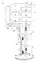
図1は、本発明の一実施の形態を示す内視鏡の斜視図、図2は、図1の内視鏡を図1の背面側から見た部分斜視図、図3は、図1の内視鏡の映像表示装置が回転自在な状態を示す部分拡大平面図、図4は、図1の内視鏡の映像表示装置の平面図である。 FIG. 1 is a perspective view of an endoscope showing an embodiment of the present invention, FIG. 2 is a partial perspective view of the endoscope of FIG. 1 viewed from the back side of FIG. 1, and FIG. 4 is a partially enlarged plan view showing a state in which the video display device of the endoscope is rotatable, and FIG. 4 is a plan view of the video display device of the endoscope of FIG.
図1に示すように、内視鏡1の内視鏡本体1bは、被検体となる体腔内の被検部位に挿入される挿入部2と、該挿入部2の基端側に連設された操作部3と、該操作部3の上端に接続された表示装置である映像表示装置4とにより主要部が構成されている。 As shown in FIG. 1, an endoscope
挿入部2は、可撓性を有する細長な形状に形成されており、先端側に位置する硬質な先端部5と、該先端部5の基端側に連設された湾曲部6と、該湾曲部6の基端側に連設された可撓部7とにより主要部が構成されている。 The
操作部3は、術者が内視鏡1を把持する際、術者により把持される把持部8と、該把持部8の基端側に設けられた操作部本体9とにより主要部が構成されている。 The
把持部8は、術者の例えば左手の親指T(図3参照)と左手のその他の指とによって包み込んで握ることができる形状、例えば棒状に外装が形成されている。尚、把持部8は、術者によって右手で握ることができる形状に形成されていても構わない。 The gripping
また、把持部8には、内視鏡1の内部に延在された後述する吸引管路100(図5、図6参照)に鉗子等の処置具を挿抜することにより、体腔内に対し処置具を挿抜する処置具挿通口10が、内視鏡1の背面1h側に設けられている。 Further, a treatment tool such as forceps is inserted into and removed from a grasping
図2に示すように、操作部本体9の内視鏡1の背面1h側には、体腔内から体液や痰等の液体を吸引する際用いられる吸引口金11が設けられている。 As shown in FIG. 2, a
吸引口金11には、図示しないチューブを介して吸引装置が接続自在である。術者は、吸引装置を作動させ、後述する吸引ボタン11a(図2参照)を操作することにより、後述する図6に示すように、一端100tが操作部本体9に開口され他端100sが先端部5の先端面5sに開口されるよう操作部3及び挿入部2内に延在された、流体管路である吸引管路100を介して、体腔内から体液や痰等を吸引することができる。 A suction device can be connected to the
尚、吸引管路100内の流路に、チューブを挿入し、該チューブに対し、吸引口金11において、体腔内に空気を送気する送気装置を接続自在としても構わない。 Note that a tube may be inserted into the flow path in the
また、操作部本体9の図1中左側には、内視鏡1の漏水検査の際に、挿入部2及び操作部3内に空気を送気するために用いられる通気口金12が設けられている。 Further, on the left side of the operation unit
通気口金12には、図示しないチューブを介して給気装置が接続自在である。術者は、給気装置を作動させ、水中にて通気口金12から内視鏡1内に空気を送り込むことにより、内視鏡1の漏水検査を行うことができる。 An air supply device can be connected to the
また、通気口金12には、内視鏡1を、滅菌処理や航空機輸送する等、陰圧下に放置する際、内視鏡1の部品、例えば先端部5の外周を被覆する図示しないゴムが陰圧により破裂することがないよう、内視鏡1の内部を大気解放させる図示しないキャップ等が着脱自在となっている。 In addition, when the endoscope 1 is left under negative pressure, such as sterilization treatment or air transportation, the
さらに、操作部本体9の内視鏡1の前面1z側には、湾曲操作ワイヤ60(図5参照)を介して、湾曲部6を、例えば上下の方向に湾曲させるための湾曲操作レバー13が設けられている。 Further, on the
湾曲操作ワイヤ60は、一端が湾曲部6内の図示しない湾曲駒の先端または先端部5に固定され、他端が操作部3内に配設された図示しないプーリ等に固定されて、挿入部2及び操作部3内に延在されている。 One end of the
湾曲操作レバー13は、把持部8を握った術者の、例えば左手の親指Tによって操作できるよう、把持部8に対し近接する位置に設けられている。また、湾曲操作レバー13は、操作部本体9の内視鏡1の前面1z側に位置された指掛部13aと、該指掛部13aに連設された腕部13bとから構成されたL字型形状を有している。 The bending
湾曲操作レバー13においては、操作部本体9を図1中左右方向に貫通する回動軸14に、腕部13bが回動自在に軸支されることにより、指掛部13aが操作部本体9の所定位置に設けられている。 In the bending
また、図2に示すように、操作部本体9の内視鏡1の背面1h側には、映像表示装置4に表示されている映像を、後述する記録制御回路31(図6参照)の記録媒体に記録させる際オンされる画像記録スイッチ15aと、その記録した画像を再生する際オンされる画像再生スイッチ15bとから構成された画像スイッチ15が設けられている。
また、操作部本体9の内視鏡1の背面1h側であって画像スイッチ15の近傍には、上述した吸引ボタン11aが設けられている。As shown in FIG. 2, on the
Further, the above-described
さらに、把持部8内には、被検体を照射する照明光を供給する照明手段である、例えば白色の発光ダイオード(以下、LEDと称す)16が、後述する手段により配設されており、さらに、操作部本体9内には、被検部位を撮像する撮像手段であるCCD、CMOS等から構成された撮像素子17が配設されている。 Further, for example, a white light emitting diode (hereinafter referred to as an LED) 16, which is an illuminating unit that supplies illuminating light for illuminating the subject, is disposed in the grasping
映像表示装置4は、箱型である略直方体形状をした装置本体18と、該装置本体18の一辺の角部から平面を形成するように内視鏡1の前面1z側に延出した指掛部であるチルトレバー19とにより外形が形成されている。 The
映像表示装置4の後述する外装部材4gの配設面4h(いずれも図7、図9参照)を構成する装置本体18の上面には、図4に示すように、撮像素子17により撮像された内視鏡画像を表示する表示部であるモニタ部21と、電源オン時に点灯するPOWER表示灯23と、内視鏡本体1bの電源をオンオフする電源スイッチ22とが設けられている。 As shown in FIG. 4, an image is picked up by the
また、映像表示装置4の外装部材4gの配設面4hを構成するチルトレバー19の上面には、記録する内視鏡画像を静止画に設定する際オンされる静止画像記録切替スイッチ24と、記録する内視鏡画像を動画に設定する際オンされる動画像記録切替スイッチ25とが設けられている。 Further, on the upper surface of the
尚、静止画像記録切替スイッチ24、動画像記録切替スイッチ25は、装置本体18の上面に設けられていても構わないし、電源スイッチ22も、チルトレバー19の上面に設けられていても構わない。 The still image
また、装置本体18の上面またはチルトレバー19の上面には、上述した画像記録スイッチ15aと画像再生スイッチ15bとが設けられていても構わない。 Further, the
また、図1に示すように、装置本体18の内視鏡1の前面1z側の面には、バッテリ34及び図示しないメモリーカード等の記憶媒体を、装置本体18内の図示しない収容部へ収容させる、または収容部から脱却させるための開閉自在な蓋体26が配設されている。 Further, as shown in FIG. 1, a storage medium such as a
装置本体18に配設されるこれらの構成要素は、水密構造を有しており、特に、開閉する蓋体26は、固定爪26aとバックルレバー26bとによって、装置本体18の収容部に対して、確実な水密構造を有している。 These components arranged in the apparatus
映像表示装置4は、装置本体18と操作部本体9との後述する接続部120(図7参照)において、図1中左右方向に貫通されて設けられた後述する回動軸55により、図3に示すように、モニタ部21が、挿入部2の挿入軸方向Jである上面を指向する方向の位置と、挿入軸方向Jと略直交する方向Pである内視鏡1の前面1z側を指向する方向の位置との間において回動自在となっている。 The
映像表示装置4の回動は、チルトレバー19が、把持部8を掴んだ術者の、例えば左手の親指Tの腹によって回動されることにより行われる。尚、チルトレバー19の上面には、複数の凸部である滑り止め20(図3参照)が形成されている。 The
次に、操作部3にLED16を配設する構成について、図5を用いて説明する。図5は、図1の内視鏡の操作部の内部の構成を概略的に示す部分拡大断面図である。 Next, a configuration in which the
図5に示すように、操作部3の把持部8の外装部材3gにより水密的に閉塞された内部には、外装部材3gの内視鏡1の前面1z側及び背面1h側に沿って、半円状に形成された板状の伝熱性フレームである金属フレーム80が互いに対向するよう挿入軸方向Jに延在されている。各金属フレーム80は、外装部材3gの内面に固定された各介装プレート81にビス95により固定されている。 As shown in FIG. 5, the inside of the
また、対向する金属フレーム80間の空間には、吸引管路100と、イメージガイド38と、湾曲操作ワイヤ60と、ライトガイドファイバが結束されて形成されたライトガイドバンドル35とが延在されており、また、バッテリ34から供給された電力を、LED16に伝達するため後述する給電制御回路30(図6参照)からLED16まで延出されたケーブル30sも延在されている。 Further, in the space between the opposing metal frames 80, a
さらに、対向する金属フレーム80間の空間には、取り付け部材であるビス90により、発光手段固定部材70が固定されている。 Further, the light emitting
尚、発光手段固定部材は、従来、湾曲操作ワイヤ60の外周に被覆されるコイルが突き当てられることにより、湾曲操作ワイヤ60が固定される部材として用いられているものである。本実施の形態の発光手段固定部材70は、従来用いられていた発光手段固定部材よりも大きく形成されている。 The light emitting means fixing member is conventionally used as a member to which the
発光手段固定部材70は、図5に示すように、例えば中実な略円柱状の部材から形成されており、例えばアルミや真鍮等の伝熱部材により形成されている。また、発光手段固定部材70には、挿入軸方向Jに沿って、貫通孔70a〜70e(貫通孔70cのみ図示されず)がそれぞれ形成されている。尚、発光手段固定部材70は、貫通孔70aと貫通孔70bとの間のみが、伝熱部材により形成されていても構わない。 As shown in FIG. 5, the light emitting
貫通孔70aは、本発明の管状部材挿通孔を構成しており、貫通孔70aには、把持部8内に延在された流体管路である吸引管路100の部位が、貫通孔70aの内周に密着するよう挿通されている。 The through
貫通孔70bは、本発明の発光手段配置空間を構成しており、後述するLEDベース76が配設される大径の孔と、ライトガイドバンドル35及びケーブル30sが挿通される小径の孔とにより段付き孔に形成されている。 The through-
貫通孔70bの小径の孔には、給電制御回路30から延出されたケーブル30sの端部側が挿通されるとともに、ライトガイドバンドル35の一端面側や、該一端面に突き当たるよう配設されたLED16が挿通されている。 The small diameter hole of the through
また、貫通孔70bの大径の孔には、ライトガイドバンドル35の一端面にLED16が突き当たるようLED16が固定された金属製のLEDベース76が挿通されている。尚、LEDベース76には、ケーブル30sの端部が接続された図示しない基板等が配設されている。また、LEDベース76は、貫通孔70bの大径の孔の内周に密着するよう固定されている。 Further, a metal LED base 76 to which the
貫通孔70cには、イメージガイド38が挿通されており、貫通孔70d、70eには、湾曲操作ワイヤ60の上述したコイルが突き当てられ、湾曲操作ワイヤ60が挿通されている。 The
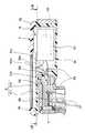
次に、図6〜図9を用いて、内視鏡1の撮像系と照明光学系とを主体とした内部の構成を説明する。図6は、図1の内視鏡の内部の構成を撮像系と照明光学系とを主体として概略的に示す図、図7は、図3中のVII-VII線に沿う操作部の一部と映像表示装置との断面図である。 Next, an internal configuration mainly composed of the imaging system and the illumination optical system of the endoscope 1 will be described with reference to FIGS. 6 is a diagram schematically showing the internal configuration of the endoscope of FIG. 1 mainly with an imaging system and an illumination optical system, and FIG. 7 is a part of the operation unit along the line VII-VII in FIG. FIG.
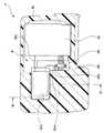
また、図8は、図7中のVIII-VIII線に沿う映像表示装置の断面図、図9は、図7中のIX-IX線に沿う映像表示装置の断面図である。 8 is a cross-sectional view of the video display device taken along line VIII-VIII in FIG. 7, and FIG. 9 is a cross-sectional view of the video display device taken along line IX-IX in FIG.
図6に示すように、映像表示装置4の枠体である外装部材4gによって水密的に閉塞された内部4iには、上述したモニタ部21及びバッテリ34の他に、光源駆動回路である給電制御回路30と記録手段である記録制御回路31と表示素子制御回路32と撮像手段である撮像素子制御回路33とが設けられている。 As shown in FIG. 6, in addition to the
ここで、映像表示装置4の外装部材4gの配設面4hには、図9に示すように、凹状の溝4mが、平面的な大きさが、上述したモニタ部21の大きさと略同じになるよう形成されている。 Here, on the
また、溝4mに、表示部材であるLCD等の表示素子(以下、LCDと称す)21Lと、該LCD21Lの表示面21LHを覆う透明なカバー部材21Cとが嵌入されて配設されている。尚、LCD21Lとカバー部材21Cとは、モニタ部21を構成している。即ち、外装部材4gは、モニタ部21を保持している。 In addition, a display element (hereinafter referred to as LCD) 21L such as an LCD, which is a display member, and a
さらに、図6に示すように、内視鏡1の内部における挿入部2から操作部3の把持部8までには、上述したライトガイドバンドル35と、イメージガイド38とが延在されている。 Further, as shown in FIG. 6, the
また、先端部5から操作部本体9までには、上述した吸引管路100が延在されており、さらに、湾曲部6から操作部本体9までには、上述した湾曲操作ワイヤ60(図6では図示されず)が延在されている
把持部8内に設けられた、LED16からの照明光は、把持部8内に、LED16に突き当てられるよう位置するライトガイドバンドル35の一端面に照射される。Further, the above-described
その後、照明光は、ライトガイドバンドル35の一端面から、先端部5に位置するライトガイドバンドル35の他端面まで伝達された後、先端部5におけるライトガイドバンドル35の他端面の先端側に設けられた照明レンズ36により、体腔内の被検部位50に向けて所定の範囲に照射される。 Thereafter, the illumination light is transmitted from one end surface of the
照明光により照射された被検部位50からの反射光による像は、先端部5に設けられた撮像レンズ40及び対物レンズ39を介して、イメージガイド38の他端に入射された後、イメージガイド38の一端まで伝達される。その後、反射光による像は、イメージガイド38の一端から、操作部本体9内に設けられた集光レンズ37を介して、撮像素子17に結像される。 The image of the reflected light from the region to be examined 50 irradiated with the illumination light is incident on the other end of the
給電制御回路30は、図9に示すように、映像表示装置4の内部4iにおいて、モニタ部21よりも外装部材4gの背面4b側の平面空間であって、背面4bとは非接触となるよう配設されている。尚、この際、外装部材4gの背面4bは、給電制御回路30から発熱された熱を放熱させる放熱部を構成している。 As shown in FIG. 9, the power
給電制御回路30は、バッテリ34から供給された電力を、LED16と撮像素子17とモニタ部21と記録制御回路31と表示素子制御回路32と撮像素子制御回路33との各々に対し、各回路に対応した駆動電力を出力する。 The power
尚、操作部3内に配設された撮像素子17、LED16へは、図7、図8に示すように、操作部3と映像表示装置4との接続部120における金属製の回動軸55内の空間55iに挿通されたケーブル30s、30mを介して駆動電力が出力される。尚、ケーブル30s、30mが、金属製の回動軸55内の空間55iに挿通されていることにより、ケーブル30s、30mからの放射ノイズは、回動軸55により遮蔽されるようになっている。 The
また、記録制御回路31、表示素子制御回路32、撮像素子制御回路33へは、映像表示装置4の内部4iにおいて、ケーブル30vを介して駆動電力が出力される。 In addition, driving power is output to the
また、給電制御回路30は、上述した電源スイッチ22を含んで構成されており、電源スイッチ22によりオン/オフが行われる。尚、バッテリ34は、繰り返し充電して使用することができる二次電池から構成されている。 The power
撮像素子17により撮像された被検部位50の像は、撮像素子17から、撮像素子17に一端が接続され、撮像素子制御回路33に他端が接続された撮像ケーブル58によって、撮像素子制御回路33に出力される。 An image of the
尚、撮像ケーブル58も、接続部120において、回動軸55内の空間55iに挿通されている。また、撮像ケーブル58は、映像表示装置4の回動によって、捻れたとしても、撮像素子17及び撮像素子制御回路33に対する、例えば半田による接続が外れてしまうことがないよう、図7に示すように、操作部本体9内及び映像表示装置4内において回動軸55の近傍に対向して設けられた一対のクランプ部材56によって、中途部位が保持されている。 Note that the
撮像素子制御回路33は、撮像素子17によって撮像された被検部位50の像を信号化して、記録制御回路31及び表示素子制御回路32へ出力する。 The image
記録制御回路31には、XDピクチャーカード等の記録媒体が着脱自在である。この記録制御回路31には、操作部本体9に設けられた画像スイッチ15(図2参照)や、映像表示装置4に設けられた静止画像記録切替スイッチ24及び動画像記録切替スイッチ25(いずれも図1参照)からの入力信号が供給される。 A recording medium such as an XD picture card is detachably attached to the
これら各種スイッチからの入力信号に応じて、記録制御回路31は、内視鏡画像の信号を静止画、或いは動画として記録、再生、静止する等の制御を行う。つまり、記録制御回路31は、撮像素子制御回路33によって信号化された被検部位50の像を、記録媒体に格納し、その格納した信号を、再生、静止等の画像再生スイッチ15bによる指示信号の入力に応じて、表示素子制御回路32へ出力する。 In response to the input signals from these various switches, the
表示素子制御回路32は、記録制御回路31、或いは撮像素子制御回路33からの信号を映像化して、モニタ部21に内視鏡画像を表示させる。また、記録制御回路31は、給電制御回路30へ、各種スイッチ15、24、25からの信号入力に応じて、LED16、撮像素子17、及び撮像素子制御回路33に対し、電力供給の指示信号を供給する。 The display
このように構成された内視鏡1は、電源スイッチ22がオンされると、映像表示装置4の給電制御回路30からそれぞれ電力が供給され、画像再生モードで起動された後、モニタ部21に記録制御回路31に記録されている画像が表示される。尚、この状態では、LED16及び撮像素子17には、給電制御回路30から電力が供給されない。 When the
その後、例えば、術者によって静止画像記録切替スイッチ24がオンされ静止画記録待機状態となると、LED16及び撮像素子17にも、給電制御回路30から電力が供給され、観察中の画像が、撮像素子17から撮像素子制御回路33、表示素子制御回路32、モニタ部21の順に伝達され、モニタ部21にリアルタイムに表示される。 Thereafter, for example, when the still image
この状態で、静止画を記録する場合は、術者によって画像記録スイッチ15aがオンされると、撮像素子制御回路33から記録制御回路31に画像信号が取り込まれ、記録制御回路31の記録媒体である内部メモリに静止画が記録される。尚、記録後は、自動的に、再度モニタ部21に観察中の画像が表示される。 When recording a still image in this state, when the
その後、術者により画像再生スイッチ15bがオンされると、記録制御回路31から表示素子制御回路32に画像信号が出力され、記録された静止画像がモニタ部21に表示される。その後、術者により、画像再生スイッチ15bがオフされると、モニタ部21には、静止画像の表示に変わって、観察中の画像が表示される。 Thereafter, when the
また、この状態で、術者により、動画像記録切替スイッチ25がオンされると、動画記録待機状態となり、この場合も、観察中の画像が、撮像素子17から撮像素子制御回路33、表示素子制御回路32、モニタ部21の順に伝達され、モニタ部21にリアルタイムに表示される。 In this state, when the operator turns on the moving image recording changeover switch 25, the moving image recording standby state is set. In this case, the image being observed is transferred from the
この状態で、動画を記録する場合は、術者により画像記録スイッチ15aがオンされると、前述と同様に記録制御回路31の内部メモリに動画が記録される。 When recording a moving image in this state, when the operator turns on the
動画記録中は、撮像素子制御回路33あるいは記録制御回路31のいずれかより表示素子制御回路32にリアルタイムに画像信号が出力され、観察画像がモニタ部21にリアルタイムで表示される。 During moving image recording, either the image
その後、術者により、画像記録スイッチ15aがオフされると、記録が停止し、モニタ部21には、動画像の表示に変わって、観察中の画像が表示される。続いて、動画再生を行う場合には、術者により画像再生スイッチ15bがオンされると、静止画再生と同様の動画再生の制御が行われる。動画再生終了時は、前述の静止画再生終了と同様な制御が行われ、上述の起動時の状態に戻る。 Thereafter, when the
次に、このように構成された本実施の形態の作用について説明する。尚、以下に示す作用は、LED16の操作部3内における放熱方法及び給電制御回路30の映像表示装置4内における放熱方法の作用について説明する。 Next, the operation of the embodiment configured as described above will be described. In addition, the effect | action shown below demonstrates the effect | action of the thermal radiation method in the
先ず、内視鏡1の電源スイッチ22がオンされ後、静止画像記録切替スイッチ24または動画像記録切替スイッチ25がオンされると、映像表示装置4の給電制御回路30からケーブル30sを介してLED16に電力が供給される。その結果、LED16は発光を開始し、該LED16により発光された照明光は、ライドガイドバンドル35を介して、照明レンズ36により、体腔内の被検部位50に向けて所定の範囲に照射される。 First, when the
この際、2枚の金属フレーム80間において固定された発光手段固定部材70の貫通孔70b内において、LED16の発光に伴いLED16から熱Nが放熱される。該貫通孔70b内に放熱されたLED16の熱Nは、LEDベース76が金属部材から形成され、発光手段固定部材70が伝熱部材から形成されていることにより、発光手段固定部材70の貫通孔70aの外周の一部が密着する吸引管路100に対し、LEDベース76、発光手段固定部材70を介して熱伝達される(図5参照)。 At this time, heat N is radiated from the
その後、吸引ボタン11aがオンされ、吸引口金11に接続された吸引装置が駆動されることにより、吸引管路100の内部の流路には、体腔内から吸引された体液や痰等の流体が流れる。よって、LED16から放熱された熱Nは、吸引管路100の内部の流路を流れる流体に吸熱され、該流体とともに、吸引口金11から、内視鏡1外に排出される。 Thereafter, the
即ち、内視鏡1の前面1z側に位置する術者に対し離間する方向である内視鏡1の背面1h側に設けられた吸引口金11から、熱Nは、内視鏡1外に排出される。 That is, heat N is discharged out of the endoscope 1 from the
また、内視鏡1の電源スイッチ22がオンされると、駆動に伴い給電制御回路30からも熱Nが放熱される。この際、給電制御回路30は、映像表示装置4の外装部材4gにより閉塞された内部4iにおいて、術者が観察するモニタ部21の裏面側、具体的には、外装部材4gの背面4b側に位置するよう設けられていることにより、熱Nは、図9に示すように、術者から離間する放熱部を構成する背面4bから、術者に対して、離間する方向に排出される。 Further, when the
尚、このことは、映像表示装置4において、モニタ部21が挿入部2の挿入軸方向Jである上面を指向する方向に位置していても、挿入軸方向Jと略直交する方向Pである内視鏡1の前面1z側を指向する方向に位置していても同様である。 Note that this is the direction P that is substantially orthogonal to the insertion axis direction J even if the
このように、本実施の形態においては、LED16を操作部3の把持部8における外装部材3gにより水密的に覆われた空間内に配設するに際し、外装部材3gに固定された2枚の金属フレーム80間に、伝熱部材から形成された発光手段固定部材70が固定され、該発光手段固定部材70に、貫通孔70a、70bが形成され、貫通孔70bに、LED16を配置し、貫通孔70aに、吸引管路100を挿通させると示した。 As described above, in the present embodiment, when the
また、給電制御回路30を、映像表示装置4の外装部材4gによって覆われた内部4iに配設するに際し、給電制御回路30を、内部4iにおいて、モニタ部21よりも外装部材4gの背面4b側に配設すると示した。 Further, when the power
このことによれば、LED16が、発光に伴い発熱した際、該熱Nは、発光手段固定部材70における熱伝導を介して、吸引管路100に熱伝達され、吸引管路100を介して、内視鏡1の前面1z側に位置する術者から離間する内視鏡1の背面1h側に設けられた吸引口金11から放熱されるため、LED16の熱Nを、術者を回避する方向に確実に排出することができる。 According to this, when the
また、給電制御回路30が、駆動に伴い発熱した際、該熱Nは、モニタ部21の背面側となる映像表示装置4の外装部材4gの背面4bから、内視鏡1の背面1h側に放熱されるため、給電制御回路30の熱Nを、内視鏡1の前面1z側に位置しモニタ部21を観察する術者を回避する方向に確実に排出することができる。 Further, when the power
また、外装部材4gの背面4bからの放熱の際、給電制御回路30は背面4bに非接触に配設されていることから、背面4bが熱され難いため、術者が背面4bに熱さにより触れ難くなってしまうことがない。 Further, when heat is radiated from the
さらに、LED16が操作部3内に設けられており、給電制御回路30が映像表示装置4内に設けられているため、LED16と給電制御回路30とが内視鏡1において、離れた場所にそれぞれ設けられていることから、内視鏡1において、LED16と給電制御回路30とからの放熱により、局所的に熱されてしまう箇所が形成されてしまうことがない。即ち、内視鏡1において熱Nの分散効率が高められることにより、局所的に放熱された熱Nにより、術者が暑さによって不快に感じてしまうことがない。 Further, since the
以上から、光源の熱のみならず、給電制御回路30の熱をも、内視鏡1を使用する術者以外の方向に確実に放熱することができる構成を有する内視鏡1を提供することができる。 As described above, it is possible to provide the endoscope 1 having a configuration capable of reliably radiating not only the heat of the light source but also the heat of the power
尚、以下変形例を示す。図10は、操作部の一部と映像表示装置との内部の構成の変形例を示す断面図である。 A modification will be described below. FIG. 10 is a cross-sectional view illustrating a modification of the internal configuration of a part of the operation unit and the video display device.
本実施の形態においては、給電制御回路30は、映像表示装置4の内部4iにおいて、モニタ部21の背面側に設けられていると示した。 In the present embodiment, the power
これに限らず、モニタ部21の背面側であれば、図10に示すように、給電制御回路30は、内部4iにおいて、外装部材4gの背面4bに対して固定して設けられていても構わない。 However, the power
この場合、背面4bは、給電制御回路30が固定されているため本実施の形態よりもより熱されてしまい、術者により背面4bが触り難くなってしまうといった問題もあるが、該問題を除けば、本実施の形態よりも、背面4bからより積極的に、給電制御回路30の熱Nを放熱させることができる。 In this case, the
また、本実施の形態においては、LED16及び撮像素子17は、操作部3内に配設されていると示したが、これに限らず、挿入部2の先端部5内に配設されている場合に適用しても、本実施の形態と同様の効果を得ることができる。 In the present embodiment, the
さらに、本実施の形態においては、映像表示装置4内に、給電制御回路30と撮像素子制御回路33とが別途に設けられている例を示したが、これに限らず、給電制御回路30と撮像素子制御回路33とは、一体的に形成されていても構わない。この場合、撮像素子制御回路33の駆動に伴う熱Nをも、より効率的に、外装部材4gの背面4b側から術者以外の方向に排出することができる。 Furthermore, in the present embodiment, an example in which the power
また、本実施の形態においては、給電制御回路30は、映像表示装置4の内部4iに配設されていると示した。これに限らず、操作部3内及び挿入部2内に設けられていても構わない。 Further, in the present embodiment, the power
この場合、内視鏡1内に、操作部3内または挿入部2内の給電制御回路30から、回動軸55の空間55iを通過して、映像表示装置4の背面4bに接続される、例えばヒートシンク等の細長な伝熱部材が設けられておれば、例えば給電制御回路30がLED16と同じ場所に設けられていたとしても、給電制御回路30の熱Nは、細長な伝熱部材を介して、本実施の形態同様、確実に、映像表示装置4の放熱部となる背面4b側から放熱されることから、本実施の形態と同様の効果を得ることができる。 In this case, the endoscope 1 is connected to the
また、本実施の形態においては、流体管路は、吸引管路100を例に挙げて示したが、これに限らず、内視鏡1内に、例えば前方送水管路等の流体が流れる管路が延在されており、該管路の操作部3側の開口が術者以外の方向を指向している場合には、該管路にLED16から放熱された熱Nを熱伝達するようにしてもよい。即ち、流体が流れる管路であって、操作部3側の開口が術者以外の方向を指向していれば、どの管路にLED16から放熱された熱Nを熱伝達するように構成しても構わない。 Further, in the present embodiment, the fluid conduit is shown by taking the
また、本実施の形態においては、内視鏡1は、医療用の内視鏡を例に挙げて示したが、工業用の内視鏡に適用しても本実施の形態と同様の効果を得ることができる。 Further, in the present embodiment, the endoscope 1 is shown by taking a medical endoscope as an example. However, even when applied to an industrial endoscope, the same effect as the present embodiment is obtained. Obtainable.
1…内視鏡
2…挿入部
3…操作部
4…映像表示装置
4g…外装部材
4b…背面
4h…配設面
4m…溝
15a…画像記録スイッチ15a
15b…画像再生スイッチ15b
16…LED
17…撮像素子
21…モニタ部
21C…カバー部材
21L…LCD
21LH…表示面
22…電源スイッチ
24…静止画像記録切替スイッチ
25…動画像記録切替スイッチ
30…給電制御回路
30s…ケーブル
31…記録制御回路
33…撮像素子制御回路
55…回動軸
55i…空間
70…照明手段固定部材
70a…貫通孔
70b…貫通孔
100…吸引管路
120…接続部
J…挿入軸方向
P…挿入軸方向と直交する方向DESCRIPTION OF SYMBOLS 1 ...
15b ...
16 ... LED
17 ...
21LH ...
Claims (9)
Translated fromJapanese前記挿入部の基端側に連設された操作部と、
前記挿入部内または前記操作部内に設けられた、前記被検体を照射する照明光を供給する照明手段と、
前記挿入部内または前記操作部内に設けられた、前記被検体の被検部位を撮像する撮像手段と、
前記操作部に接続された、前記撮像手段により撮像された前記被検部位の内視鏡画像が表示される表示部と該表示部を保持する枠体とを具備する表示装置と、
前記挿入部内と前記操作部内と前記表示装置内とのいずれかに設けられた、前記照明手段に電力を供給して、前記照明手段における前記照明光の供給を駆動する光源駆動回路と、
前記表示装置における前記表示部が配設される前記枠体の配設面に対向する背面に形成された、前記光源駆動回路から発熱された熱を放熱させる放熱部と、
を具備していることを特徴とする内視鏡。An elongated insertion part to be inserted into the subject;
An operation unit continuously provided on the proximal end side of the insertion unit;
An illuminating means for illuminating the subject provided in the insertion section or the operation section;
An imaging means provided in the insertion section or in the operation section for imaging a test site of the subject;
A display device that is connected to the operation unit and includes a display unit that displays an endoscopic image of the examination site imaged by the imaging unit; and a frame that holds the display unit;
A light source driving circuit that is provided in any one of the insertion unit, the operation unit, and the display device, supplies power to the illumination unit, and drives the supply of the illumination light in the illumination unit;
A heat dissipating part for dissipating heat generated from the light source driving circuit, formed on the back surface opposite to the disposition surface of the frame on which the display unit is disposed in the display device;
An endoscope characterized by comprising:
前記枠体の前記配設面には、前記記録手段に記録する前記内視鏡画像を静止画または動画に設定する切替スイッチと、前記記録手段に前記内視鏡画像の記録を指示するスイッチと、前記表示装置に前記内視鏡画像の表示を指示するスイッチと、前記挿入部と前記操作部と前記表示装置とを具備する内視鏡本体の電源のオンオフを指示するスイッチとのすくなくとも1つが設けられていることを特徴とする請求項1〜3のいずれか1項に記載の内視鏡。In the operation unit or the display device, a recording unit that records the endoscopic image captured by the imaging unit is further provided,
On the arrangement surface of the frame, a switch for setting the endoscope image to be recorded on the recording means to be a still image or a moving image, and a switch for instructing the recording means to record the endoscope image And at least one of a switch for instructing the display device to display the endoscopic image and a switch for instructing on / off of the power supply of the endoscope body including the insertion portion, the operation portion, and the display device. The endoscope according to any one of claims 1 to 3, wherein the endoscope is provided.
前記溝に、前記表示部を構成する表示部材と該表示部材の表示面を覆うカバー部材とが嵌入されて配設されていることを特徴とする請求項1〜4のいずれか1項に記載の内視鏡。A groove is formed on the arrangement surface of the frame,
The display member which comprises the said display part, and the cover member which covers the display surface of this display member are inserted and arrange | positioned by the said groove | channel, The any one of Claims 1-4 characterized by the above-mentioned. Endoscope.
Priority Applications (4)
| Application Number | Priority Date | Filing Date | Title |
|---|---|---|---|
| JP2006184784AJP2008011992A (en) | 2006-07-04 | 2006-07-04 | Endoscope |
| EP07011566.2AEP1875853B1 (en) | 2006-07-04 | 2007-06-13 | Endoscope and display device including a heat radiation portion |
| US11/821,645US8641605B2 (en) | 2006-07-04 | 2007-06-25 | Endoscope |
| CN2007101269405ACN101099662B (en) | 2006-07-04 | 2007-07-03 | Endoscope |
Applications Claiming Priority (1)
| Application Number | Priority Date | Filing Date | Title |
|---|---|---|---|
| JP2006184784AJP2008011992A (en) | 2006-07-04 | 2006-07-04 | Endoscope |
Publications (1)
| Publication Number | Publication Date |
|---|---|
| JP2008011992Atrue JP2008011992A (en) | 2008-01-24 |
Family
ID=38521641
Family Applications (1)
| Application Number | Title | Priority Date | Filing Date |
|---|---|---|---|
| JP2006184784APendingJP2008011992A (en) | 2006-07-04 | 2006-07-04 | Endoscope |
Country Status (4)
| Country | Link |
|---|---|
| US (1) | US8641605B2 (en) |
| EP (1) | EP1875853B1 (en) |
| JP (1) | JP2008011992A (en) |
| CN (1) | CN101099662B (en) |
Cited By (2)
| Publication number | Priority date | Publication date | Assignee | Title |
|---|---|---|---|---|
| JP2011036365A (en)* | 2009-08-10 | 2011-02-24 | Olympus Corp | Endoscope apparatus |
| JP2017169983A (en)* | 2016-03-25 | 2017-09-28 | オリンパス株式会社 | Endoscope |
Families Citing this family (45)
| Publication number | Priority date | Publication date | Assignee | Title |
|---|---|---|---|---|
| DE102007032200B4 (en)* | 2007-07-11 | 2010-09-09 | Schölly Fiberoptic GmbH | endoscope |
| JP5139742B2 (en) | 2007-08-03 | 2013-02-06 | オリンパスメディカルシステムズ株式会社 | Endoscope |
| US8767060B2 (en)* | 2007-10-26 | 2014-07-01 | Ge Inspection Technologies, Lp | Inspection apparatus having heat sink assembly |
| US8253782B2 (en)* | 2007-10-26 | 2012-08-28 | Ge Inspection Technologies, Lp | Integrated storage for industrial inspection handset |
| US8310604B2 (en) | 2007-10-26 | 2012-11-13 | GE Sensing & Inspection Technologies, LP | Visual inspection apparatus having light source bank |
| US7902990B2 (en)* | 2007-10-26 | 2011-03-08 | Ge Inspection Technologies, Lp | Battery and power management for industrial inspection handset |
| US20090106948A1 (en)* | 2007-10-26 | 2009-04-30 | Lopez Joseph V | Method and apparatus for retaining elongated flexible articles including visual inspection apparatus inspection probes |
| GB2470327B (en)* | 2008-03-07 | 2012-03-21 | Milwaukee Electric Tool Corp | Visual inspection device |
| CA2717860C (en) | 2008-03-07 | 2016-11-08 | Milwaukee Electric Tool Corporation | Battery pack for use with a power tool and a non-motorized sensing tool |
| WO2010019113A1 (en)* | 2008-08-08 | 2010-02-18 | Pustovarov Sergej Yurievich | Video photo endoscopic device |
| JP4889811B2 (en)* | 2009-03-02 | 2012-03-07 | オリンパスメディカルシステムズ株式会社 | Endoscope |
| RU2390305C1 (en)* | 2009-03-04 | 2010-05-27 | Общество с ограниченной ответственностью "Научно Производственная Компания "АЗИМУТ" | Videoendoscopic system |
| JP4897117B1 (en) | 2010-12-24 | 2012-03-14 | オリンパス株式会社 | Endoscope device |
| CN102711581B (en) | 2010-12-24 | 2014-01-29 | 奥林巴斯株式会社 | endoscopic device |
| JP4897116B1 (en) | 2010-12-24 | 2012-03-14 | オリンパス株式会社 | Endoscope device |
| CN102665523B (en) | 2010-12-24 | 2013-08-28 | 奥林巴斯株式会社 | Endoscopic device |
| WO2012134469A1 (en)* | 2011-03-31 | 2012-10-04 | Ingersoll-Rand Company | Display assemblies having integrated display covers and light pipes and handheld power tools and methods including same |
| HK1198738A1 (en) | 2011-05-03 | 2015-06-05 | Endosee股份有限公司 | Method and apparatus for hysteroscopy and endometrial biopsy |
| US9788755B2 (en)* | 2011-05-26 | 2017-10-17 | Covidien Lp | Illumination systems and devices for tracheal tubes |
| US8182416B1 (en) | 2011-08-02 | 2012-05-22 | Olympus Corporation | Endoscopic device |
| US8177710B1 (en) | 2011-08-02 | 2012-05-15 | Olympus Corporation | Endoscopic device |
| USD678524S1 (en)* | 2011-12-14 | 2013-03-19 | Hubitools S.A. | Endoscope |
| US9468367B2 (en) | 2012-05-14 | 2016-10-18 | Endosee Corporation | Method and apparatus for hysteroscopy and combined hysteroscopy and endometrial biopsy |
| US9622646B2 (en) | 2012-06-25 | 2017-04-18 | Coopersurgical, Inc. | Low-cost instrument for endoscopically guided operative procedures |
| KR102027251B1 (en)* | 2012-11-22 | 2019-10-01 | 삼성전자주식회사 | Endoscope |
| ES2735335T3 (en)* | 2013-12-13 | 2019-12-18 | Integrated Endoscopy Inc | Medical imaging device that uses a thermally conductive lens cradle |
| US11033182B2 (en) | 2014-02-21 | 2021-06-15 | 3Dintegrated Aps | Set comprising a surgical instrument |
| TWI539112B (en)* | 2014-05-01 | 2016-06-21 | 王訓忠 | Cooling of integrated led lights and micro camera for minimally invasive surgeries |
| CN108024806B (en) | 2015-07-21 | 2022-07-01 | 3D集成公司 | Cannula assembly kit, trocar assembly kit, sleeve assembly, minimally invasive surgical system and method thereof |
| US11020144B2 (en) | 2015-07-21 | 2021-06-01 | 3Dintegrated Aps | Minimally invasive surgery system |
| DK178899B1 (en) | 2015-10-09 | 2017-05-08 | 3Dintegrated Aps | A depiction system |
| CN108471929A (en)* | 2016-01-20 | 2018-08-31 | 奥林巴斯株式会社 | Portable endoscope |
| US10702305B2 (en) | 2016-03-23 | 2020-07-07 | Coopersurgical, Inc. | Operative cannulas and related methods |
| WO2018003322A1 (en)* | 2016-06-30 | 2018-01-04 | 富士フイルム株式会社 | Ultrasonic endoscope |
| CN106267520A (en)* | 2016-08-29 | 2017-01-04 | 李安 | Image acquisition embedded device and stomach tube system for stomach tube |
| JP6893420B2 (en)* | 2017-02-06 | 2021-06-23 | 株式会社山田製作所 | Shaft and yoke assembly |
| JP6395973B1 (en)* | 2017-02-22 | 2018-09-26 | オリンパス株式会社 | Endoscope operation section and endoscope having the same |
| CA3004556C (en)* | 2017-05-11 | 2023-10-24 | Ian Schoonbaert | Video laryngoscope with monitor stabilization |
| EP3790444A1 (en)* | 2018-05-09 | 2021-03-17 | CONMED Corporation | Flexible light guide and heat sink for endoscopic systems |
| CN109124548B (en)* | 2018-07-09 | 2024-07-09 | 卓外(上海)医疗电子科技有限公司 | Electronic endoscope with good heat treatment |
| US11203520B2 (en) | 2018-11-29 | 2021-12-21 | Green Co2 Ip Llc | Pressurized liquid fill gun apparatus and method of use |
| USD892277S1 (en)* | 2018-12-21 | 2020-08-04 | Green Co2 Ip, Llc | Fill gun socket |
| CN109752837B (en)* | 2019-02-02 | 2024-03-29 | 深圳市艾丽尔特科技有限公司 | Cold light source for endoscope and endoscope using same |
| CN113440084A (en)* | 2020-03-25 | 2021-09-28 | 帝视寰宇医材股份有限公司 | Disinfecting sleeve for endoscope or endoscope |
| US11536381B2 (en) | 2021-04-27 | 2022-12-27 | Green Co2 Ip, Llc | Dynamic control valve assembly |
Citations (18)
| Publication number | Priority date | Publication date | Assignee | Title |
|---|---|---|---|---|
| JPS63502728A (en)* | 1986-02-24 | 1988-10-13 | アメリカン・サイアナミド・カンパニー | Surgical instruments for cleaning, suction and illumination |
| JPH08307745A (en)* | 1995-04-20 | 1996-11-22 | Samsung Electron Co Ltd | Video camera with LCD monitor and TV projector adapter |
| JPH09187414A (en)* | 1996-01-08 | 1997-07-22 | Olympus Optical Co Ltd | Endoscope apparatus |
| JPH09285443A (en)* | 1996-04-25 | 1997-11-04 | Fuji Photo Optical Co Ltd | Electronic endoscope apparatus |
| JPH119548A (en)* | 1997-06-25 | 1999-01-19 | Fuji Photo Optical Co Ltd | Portable electronic endoscope |
| JPH11216113A (en)* | 1998-02-03 | 1999-08-10 | Olympus Optical Co Ltd | Endoscope device |
| JPH11267099A (en)* | 1998-03-24 | 1999-10-05 | Olympus Optical Co Ltd | Endoscope |
| US20020022769A1 (en)* | 1999-03-03 | 2002-02-21 | Smith Vincent A. | Portable video laryngoscope |
| JP2002177197A (en)* | 2000-12-14 | 2002-06-25 | Asahi Optical Co Ltd | Endoscope tip |
| JP2002232174A (en)* | 2001-02-06 | 2002-08-16 | Hitachi Ltd | Electronic equipment |
| JP2002288978A (en)* | 2001-03-22 | 2002-10-04 | Sony Corp | Electronics |
| US6692432B1 (en)* | 1996-07-15 | 2004-02-17 | East Giant Limited | Hand-held portable camera for producing video images of an object |
| JP2005084192A (en)* | 2003-09-05 | 2005-03-31 | Sony Corp | Electronic apparatus |
| JP2005101779A (en)* | 2003-09-22 | 2005-04-14 | Olympus Corp | Camera |
| JP2005192739A (en)* | 2004-01-06 | 2005-07-21 | Olympus Corp | Endoscope apparatus |
| JP2005204886A (en)* | 2004-01-22 | 2005-08-04 | Olympus Corp | Endoscope |
| JP2005218644A (en)* | 2004-02-05 | 2005-08-18 | Chinontec Kk | Endotracheal intubation apparatus |
| JP2006158516A (en)* | 2004-12-03 | 2006-06-22 | Olympus Corp | Endoscope apparatus |
Family Cites Families (17)
| Publication number | Priority date | Publication date | Assignee | Title |
|---|---|---|---|---|
| US6221007B1 (en)* | 1996-05-03 | 2001-04-24 | Philip S. Green | System and method for endoscopic imaging and endosurgery |
| JP2000112953A (en) | 1998-09-30 | 2000-04-21 | Fujitsu Kiden Ltd | Literature retrieval method and its system |
| FR2785132B1 (en)* | 1998-10-27 | 2000-12-22 | Tokendo Sarl | DISTAL COLOR CCD SENSOR VIDEOENDOSCOPIC PROBE |
| US20020087047A1 (en)* | 1999-09-13 | 2002-07-04 | Visionscope, Inc. | Miniature endoscope system |
| JP2002112953A (en) | 2000-10-10 | 2002-04-16 | Asahi Optical Co Ltd | Light source unit for portable endoscope |
| ATE301963T1 (en)* | 2002-02-25 | 2005-09-15 | Olympus Corp | ENDOSCOPE WITH COOLING DEVICE |
| US7179223B2 (en)* | 2002-08-06 | 2007-02-20 | Olympus Optical Co., Ltd. | Endoscope apparatus having an internal channel |
| JP2004109222A (en)* | 2002-09-13 | 2004-04-08 | Olympus Corp | Endoscope apparatus |
| AU2003295360A1 (en)* | 2002-10-30 | 2004-06-07 | Smith And Nephew, Inc. | Mobile endoscopic video system |
| EP1441530B1 (en)* | 2003-01-17 | 2010-04-28 | Tokendo | Video endoscope |
| US20050222499A1 (en)* | 2003-04-01 | 2005-10-06 | Banik Michael S | Interface for video endoscope system |
| JP4418202B2 (en)* | 2003-10-06 | 2010-02-17 | オリンパス株式会社 | Endoscope |
| US20060004258A1 (en)* | 2004-07-02 | 2006-01-05 | Wei-Zen Sun | Image-type intubation-aiding device |
| US7597662B2 (en)* | 2004-09-30 | 2009-10-06 | Boston Scientific Scimed, Inc. | Multi-fluid delivery system |
| JP4719225B2 (en)* | 2004-12-13 | 2011-07-06 | ジャイラス エーシーエムアイ インク | Endoscope gripping part, endoscope and manufacturing method thereof |
| US20060155168A1 (en)* | 2005-01-10 | 2006-07-13 | Pease Alfred A | Optical snake |
| US7824330B2 (en)* | 2005-11-28 | 2010-11-02 | Karl Storz Endovision, Inc. | Ceramic fiber optic taper housing for medical devices |
- 2006
- 2006-07-04JPJP2006184784Apatent/JP2008011992A/enactivePending
- 2007
- 2007-06-13EPEP07011566.2Apatent/EP1875853B1/ennot_activeNot-in-force
- 2007-06-25USUS11/821,645patent/US8641605B2/enactiveActive
- 2007-07-03CNCN2007101269405Apatent/CN101099662B/ennot_activeExpired - Fee Related
Patent Citations (18)
| Publication number | Priority date | Publication date | Assignee | Title |
|---|---|---|---|---|
| JPS63502728A (en)* | 1986-02-24 | 1988-10-13 | アメリカン・サイアナミド・カンパニー | Surgical instruments for cleaning, suction and illumination |
| JPH08307745A (en)* | 1995-04-20 | 1996-11-22 | Samsung Electron Co Ltd | Video camera with LCD monitor and TV projector adapter |
| JPH09187414A (en)* | 1996-01-08 | 1997-07-22 | Olympus Optical Co Ltd | Endoscope apparatus |
| JPH09285443A (en)* | 1996-04-25 | 1997-11-04 | Fuji Photo Optical Co Ltd | Electronic endoscope apparatus |
| US6692432B1 (en)* | 1996-07-15 | 2004-02-17 | East Giant Limited | Hand-held portable camera for producing video images of an object |
| JPH119548A (en)* | 1997-06-25 | 1999-01-19 | Fuji Photo Optical Co Ltd | Portable electronic endoscope |
| JPH11216113A (en)* | 1998-02-03 | 1999-08-10 | Olympus Optical Co Ltd | Endoscope device |
| JPH11267099A (en)* | 1998-03-24 | 1999-10-05 | Olympus Optical Co Ltd | Endoscope |
| US20020022769A1 (en)* | 1999-03-03 | 2002-02-21 | Smith Vincent A. | Portable video laryngoscope |
| JP2002177197A (en)* | 2000-12-14 | 2002-06-25 | Asahi Optical Co Ltd | Endoscope tip |
| JP2002232174A (en)* | 2001-02-06 | 2002-08-16 | Hitachi Ltd | Electronic equipment |
| JP2002288978A (en)* | 2001-03-22 | 2002-10-04 | Sony Corp | Electronics |
| JP2005084192A (en)* | 2003-09-05 | 2005-03-31 | Sony Corp | Electronic apparatus |
| JP2005101779A (en)* | 2003-09-22 | 2005-04-14 | Olympus Corp | Camera |
| JP2005192739A (en)* | 2004-01-06 | 2005-07-21 | Olympus Corp | Endoscope apparatus |
| JP2005204886A (en)* | 2004-01-22 | 2005-08-04 | Olympus Corp | Endoscope |
| JP2005218644A (en)* | 2004-02-05 | 2005-08-18 | Chinontec Kk | Endotracheal intubation apparatus |
| JP2006158516A (en)* | 2004-12-03 | 2006-06-22 | Olympus Corp | Endoscope apparatus |
Cited By (3)
| Publication number | Priority date | Publication date | Assignee | Title |
|---|---|---|---|---|
| JP2011036365A (en)* | 2009-08-10 | 2011-02-24 | Olympus Corp | Endoscope apparatus |
| US8900132B2 (en) | 2009-08-10 | 2014-12-02 | Olympus Corporation | Endoscope apparatus |
| JP2017169983A (en)* | 2016-03-25 | 2017-09-28 | オリンパス株式会社 | Endoscope |
Also Published As
| Publication number | Publication date |
|---|---|
| CN101099662A (en) | 2008-01-09 |
| EP1875853A1 (en) | 2008-01-09 |
| CN101099662B (en) | 2012-05-09 |
| US20080009677A1 (en) | 2008-01-10 |
| EP1875853B1 (en) | 2014-01-01 |
| US8641605B2 (en) | 2014-02-04 |
Similar Documents
| Publication | Publication Date | Title |
|---|---|---|
| JP2008011992A (en) | Endoscope | |
| JP5259113B2 (en) | Endoscope | |
| JP5148068B2 (en) | Endoscope | |
| JP5443677B2 (en) | Illumination device and endoscope | |
| JP5030441B2 (en) | Endoscope device | |
| JP5178239B2 (en) | Medical system | |
| JP5139742B2 (en) | Endoscope | |
| CN102333475A (en) | Illumination unit, an endoscope with the illumination unit, and an illumination probe with the illumination unit that can be inserted through the channel of the endoscope | |
| JP7076568B2 (en) | Endoscope | |
| JPWO2014065092A1 (en) | Endoscope | |
| JP2010017377A (en) | Endoscope system, light source device for endoscope, and method for controlling operation of light source device for endoscope | |
| JP5174330B2 (en) | Endoscope | |
| JP4914638B2 (en) | Endoscope, endoscope apparatus, endoscope assembly method, endoscope apparatus assembly method | |
| US20160038013A1 (en) | Sterile sleeve for medical viewing instrument and method for operating a medical instrument | |
| JP4953728B2 (en) | Ultrasound endoscope | |
| JP5184964B2 (en) | Endoscope system and connector cover | |
| JP5063419B2 (en) | Endoscope tip hood and endoscope unit including the same | |
| JP2007296112A (en) | Endoscope and endoscope apparatus | |
| JP3845275B2 (en) | Portable endoscope | |
| JP2009165640A (en) | Endoscope tip hood and endoscope unit using the same | |
| JP2015112154A (en) | Endoscope | |
| JP2009165633A (en) | Endoscope tip hood and endoscope unit using the same | |
| JP2010088657A (en) | Endoscope light source device | |
| JP4343772B2 (en) | Endoscope device | |
| JP2005270294A (en) | Endoscope apparatus |
Legal Events
| Date | Code | Title | Description |
|---|---|---|---|
| A621 | Written request for application examination | Free format text:JAPANESE INTERMEDIATE CODE: A621 Effective date:20090603 | |
| A977 | Report on retrieval | Free format text:JAPANESE INTERMEDIATE CODE: A971007 Effective date:20110907 | |
| A131 | Notification of reasons for refusal | Free format text:JAPANESE INTERMEDIATE CODE: A131 Effective date:20111101 | |
| A521 | Written amendment | Free format text:JAPANESE INTERMEDIATE CODE: A523 Effective date:20111214 | |
| A131 | Notification of reasons for refusal | Free format text:JAPANESE INTERMEDIATE CODE: A131 Effective date:20120228 | |
| A521 | Written amendment | Free format text:JAPANESE INTERMEDIATE CODE: A523 Effective date:20120419 | |
| A02 | Decision of refusal | Free format text:JAPANESE INTERMEDIATE CODE: A02 Effective date:20121106 |