JP2008011611A - Electric motor - Google Patents
Electric motorDownload PDFInfo
- Publication number
- JP2008011611A JP2008011611AJP2006177708AJP2006177708AJP2008011611AJP 2008011611 AJP2008011611 AJP 2008011611AJP 2006177708 AJP2006177708 AJP 2006177708AJP 2006177708 AJP2006177708 AJP 2006177708AJP 2008011611 AJP2008011611 AJP 2008011611A
- Authority
- JP
- Japan
- Prior art keywords
- plate
- substrate
- motor
- rotation axis
- fixed
- Prior art date
- Legal status (The legal status is an assumption and is not a legal conclusion. Google has not performed a legal analysis and makes no representation as to the accuracy of the status listed.)
- Pending
Links
- 239000000758substrateSubstances0.000claimsabstractdescription103
- 230000004907fluxEffects0.000abstractdescription7
- 230000014759maintenance of locationEffects0.000abstract1
- 230000002093peripheral effectEffects0.000description21
- 239000004020conductorSubstances0.000description15
- 125000006850spacer groupChemical group0.000description10
- 238000000034methodMethods0.000description8
- 239000000463materialSubstances0.000description5
- 238000004804windingMethods0.000description5
- 230000000694effectsEffects0.000description4
- 230000004048modificationEffects0.000description4
- 238000012986modificationMethods0.000description4
- 239000000696magnetic materialSubstances0.000description3
- 229910000679solderInorganic materials0.000description3
- RYGMFSIKBFXOCR-UHFFFAOYSA-NCopperChemical compound[Cu]RYGMFSIKBFXOCR-UHFFFAOYSA-N0.000description2
- XEEYBQQBJWHFJM-UHFFFAOYSA-NIronChemical compound[Fe]XEEYBQQBJWHFJM-UHFFFAOYSA-N0.000description2
- 239000000853adhesiveSubstances0.000description2
- 230000001070adhesive effectEffects0.000description2
- 230000004323axial lengthEffects0.000description2
- 239000011889copper foilSubstances0.000description2
- 239000002184metalSubstances0.000description2
- 229910052751metalInorganic materials0.000description2
- 230000003287optical effectEffects0.000description2
- 238000003825pressingMethods0.000description2
- 230000005855radiationEffects0.000description2
- 238000013459approachMethods0.000description1
- 238000005452bendingMethods0.000description1
- 230000000295complement effectEffects0.000description1
- 239000013039cover filmSubstances0.000description1
- 238000005516engineering processMethods0.000description1
- 229910052742ironInorganic materials0.000description1
- 238000010030laminatingMethods0.000description1
- WABPQHHGFIMREM-UHFFFAOYSA-Nlead(0)Chemical compound[Pb]WABPQHHGFIMREM-UHFFFAOYSA-N0.000description1
- 238000004519manufacturing processMethods0.000description1
- 229920001721polyimidePolymers0.000description1
- 239000009719polyimide resinSubstances0.000description1
- 230000002265preventionEffects0.000description1
- 230000009467reductionEffects0.000description1
- 238000005476solderingMethods0.000description1
Images


Landscapes
- Permanent Magnet Type Synchronous Machine (AREA)
Abstract
Description
Translated fromJapanese本発明は、モータに係り、特に、駆動コイルとマグネットとを回転軸方向に対向させた扁平のモータにおける薄型化の技術に関する。 The present invention relates to a motor, and more particularly, to a technology for reducing the thickness of a flat motor in which a drive coil and a magnet are opposed to each other in the rotation axis direction.
駆動コイルとマグネットとを回転軸方向に対向させた、いわゆる扁平モータ(平板モータとも称する)は、回転軸方向の厚みを薄くできることから、ノートパソコンなどに搭載される光ディスク駆動装置の駆動用モータとして特に好適である。
一方、市場においては、少スペースの観点から、ノートパソコンなどの可搬型電子機器に対しては特に薄型化が要望されており、光ディスク駆動装置の駆動用モータについても例外ではない。A so-called flat motor (also referred to as a flat plate motor) in which a drive coil and a magnet are opposed to each other in the rotation axis direction can reduce the thickness in the rotation axis direction. Therefore, as a drive motor for an optical disk drive device mounted on a notebook personal computer or the like Particularly preferred.
On the other hand, in the market, from the viewpoint of small space, there is a demand for reducing the thickness of portable electronic devices such as notebook personal computers, and the drive motor of the optical disk drive device is no exception.
この扁平モータの一例を、図5を用いて説明する。このモータ150は、ロータR側に設けられたシャフト70を、ステータS側に設けられた軸受RB,SBにより支持して、ロータRをステータSに対して回転自在にしてなるものである。
さらに詳しくは、ステータS側に複数の平板状のコイル33が円弧状に配列された基板32を備える一方、ロータR側に、環状のマグネット27が固定されて軟磁性体で形成されたロータヨーク28と、マグネット27とでコイル33を挟むように配設された対向ヨーク30と、を備えており、このマグネット27と対向ヨーク30とが、コイル33を回転軸方向に所定のエアーギャップを介して対向するように構成されている。An example of this flat motor will be described with reference to FIG. The
More specifically, a
ところで、このような扁平モータを薄型化するための方法として、例えば、基板32全体を薄くする方法がある。
しかしながら、扁平モータの製造工程においては、基板32をモータベース31に固定する前に比較的重いコイル33を取り付けるため、単に基板32を薄くしただけでは、組み立て作業においてコイル33を取り付けた薄い基板32は、その強度が不足して折れ曲がり易いという問題があった。
特に、基板32には、コイル33以外に、扁平モータの駆動や制御のためのIC等の電子部品を載せる場合が多く、これらの電子部品の基板32からの剥離を防ぐため、基板32には高い曲げ強度が求められる。
従って、この方法は好ましい方法ではない。By the way, as a method for thinning such a flat motor, for example, there is a method of thinning the
However, in the flat motor manufacturing process, since the relatively
In particular, in addition to the
This method is therefore not a preferred method.
また、この方法以外にも、扁平モータを薄型化する技術が種々提案されているが、その一例が特許文献1に開示されている。
この特許文献1の図7を用いて説明すると、平板コイル33を支持する基板32に、回転軸を中心とし周方向に配置された複数の平板コイル群の外周径よりも小径の円形孔を設け、平板コイル33をその外周側の環状領域のみを基板32に固定して支持し、円形孔にロータのバックヨーク30が侵入するように配置することで、扁平モータの軸方向長さを短縮する構成である。
この構成によれば、軟磁性体であるバックヨークが平板コイルにより接近して磁気回路のエアーギャップが狭まり、モータの薄型化と特性の向上が図れるものとされる。In addition to this method, various techniques for reducing the thickness of the flat motor have been proposed. An example is disclosed in
Referring to FIG. 7 of
According to this configuration, the back yoke, which is a soft magnetic material, approaches the flat plate coil, the air gap of the magnetic circuit is narrowed, and the motor can be made thinner and the characteristics can be improved.
しかしながら、この特許文献1に記載された技術においては、平板コイルの外周側の環状領域しか基板と重なっていない。
従って、平板コイルと基板との間の半田付けにより電気接続を行う場所が限定され、コイルへの給電構造に制約が生じる課題があった。
また、平板コイルへの通電を切り替えるためにロータ側からの磁束を検知するホール素子などのセンサを取り付ける場所がない、あるいは、極めて限定されてしまう、という課題があった。
また、当然であるが、平板コイルの保持強度が小さいという課題があった。However, in the technique described in
Therefore, the place where electrical connection is made by soldering between the flat coil and the substrate is limited, and there is a problem that the structure for feeding the coil is restricted.
In addition, there is a problem that there is no place to attach a sensor such as a Hall element that detects magnetic flux from the rotor side in order to switch energization to the flat plate coil, or that the position is extremely limited.
Further, as a matter of course, there is a problem that the holding strength of the flat coil is small.
そこで、本発明が解決しようとする課題は、平板コイルへの給電構造に制約が生じ難く、磁束を検知するセンサの取り付け場所が確保し易く、平板コイルの保持強度が高く得られ、なおかつ薄型化が可能なモータを提供することにある。 Therefore, the problem to be solved by the present invention is that the structure for supplying power to the flat plate coil is not easily restricted, it is easy to secure the mounting location of the sensor for detecting the magnetic flux, the holding strength of the flat plate coil is high, and the thickness is reduced. It is to provide a motor capable of performing the above.
上記の課題を解決するために、本願発明は手段として次の1)〜3)の構成を有する。
1)モータベース(1)と、回転軸(CL)に直交して前記モータベース(1)に固定された基板(3)と、該基板(3)の一面上に、前記回転軸(CL)を中心とする円弧状にて配列固定された複数の平板コイル(4)と、該複数の平板コイル(4)及び前記基板(3)を挟むように前記回転軸(CL)方向に配設されたプレート(10)及び環状のマグネット(9)と、を有し、前記複数の平板コイル(4)に対して、前記回転軸(CL)回りに前記プレート(10)及び環状のマグネット(8)が相対的に回転する構成とされて成り、
前記基板(3)は、2以上の層数を有する多層基板であると共に、前記モータベース(1)に固定されている範囲の層数よりも、前記複数の平板コイル(4)と、該平板コイル(4)との間に前記基板(3)を挟む前記プレート(10)又は前記マグネット(9)とが前記回転軸(CL)方向に重なる範囲の層数を少なくされて成ることを特徴とするモータ(50)である。
2)モータベース(1)と、一面が前記モータベース(1)に固定されると共に、他面側にフレキシブル基板(33)が接合されて成るコア基板(3)と、該フレキシブル基板(33)上に、前記回転軸(CL)を中心とする円弧状にて配列固定された複数の平板コイル(4)と、該複数の平板コイル(4)及び前記フレキシブル基板(33)を挟むように前記回転軸(CL)方向に配設されたプレート(10)及び環状のマグネット(9)と、を有し、前記複数の平板コイル(4)に対して、前記回転軸(CL)回りに前記プレート(10)及び環状のマグネット(8)が相対的に回転する構成とされて成り、
前記コア基板(3)は、前記複数の平板コイル(4)と、該平板コイルとの間に前記フレキシブル基板(33)を挟む前記プレート(10)又は前記マグネット(9)とが前記回転軸(CL)方向に重なる範囲を含んで開口する開口部(3f)を有して成ることを特徴とするモータ(50)である。
3)モータベース(1)と、一面が前記モータベース(1)に固定されると共に、他面側にフレキシブル基板(33)が接合されて成るコア基板(3)と、
前記フレキシブル基板(33)上に、前記回転軸(CL)を中心とする円弧状にて配列固定された複数の平板コイル(4)と、該複数の平板コイル(4)及び前記フレキシブル基板(33)を挟むように前記回転軸(CL)方向に配設されたプレート(10)及び環状のマグネット(8)と、を有し、前記複数の平板コイル(4)に対して、前記回転軸(CL)回りに前記プレート(10)及び環状のマグネット(9)が相対的に回転する構成とされて成り、
前記コア基板(3)は、2以上の層数を有する多層基板であると共に、前記モータベース(1)に固定されている範囲の層数よりも、前記複数の平板コイル(4)と、該平板コイルとの間に前記フレキシブル基板(33)を挟む前記プレート(10)又は前記マグネット(8)とが前記回転軸(CL)方向に重なる範囲の層数を少なくされて成ることを特徴とするモータ(50)である。In order to solve the above problems, the present invention has the following configurations 1) to 3) as means.
1) A motor base (1), a substrate (3) fixed to the motor base (1) orthogonal to the rotation axis (CL), and the rotation shaft (CL) on one surface of the substrate (3) Are arranged in the direction of the rotation axis (CL) so as to sandwich the plurality of plate coils (4) and the substrate (3). Plate (10) and an annular magnet (9), and the plate (10) and the annular magnet (8) around the rotation axis (CL) with respect to the plurality of flat plate coils (4). Is configured to rotate relatively,
The substrate (3) is a multilayer substrate having a number of layers of 2 or more, and the plurality of plate coils (4) and the plate are more than the number of layers fixed to the motor base (1). The number of layers in a range where the plate (10) or the magnet (9) sandwiching the substrate (3) between the coil (4) and the magnet (9) overlaps in the direction of the rotation axis (CL) is reduced. Motor (50) to be used.
2) A motor base (1), a core substrate (3), one surface of which is fixed to the motor base (1) and a flexible substrate (33) joined to the other surface, and the flexible substrate (33) A plurality of plate coils (4) arranged and fixed in an arc shape centered on the rotation axis (CL), and the plurality of plate coils (4) and the flexible substrate (33) are sandwiched between A plate (10) and an annular magnet (9) disposed in the direction of the rotation axis (CL), and the plate around the rotation axis (CL) with respect to the plurality of plate coils (4) (10) and the annular magnet (8) are configured to rotate relatively,
The core substrate (3) includes the plurality of plate coils (4) and the plate (10) or the magnet (9) sandwiching the flexible substrate (33) between the plate coils. The motor (50) is characterized by having an opening (3f) that opens to include a range overlapping in the CL) direction.
3) A motor base (1), a core substrate (3) formed by bonding one surface of the motor base (1) to the motor base (1) and a flexible substrate (33) on the other surface side;
A plurality of plate coils (4) arrayed and fixed on the flexible substrate (33) in an arc shape centered on the rotation axis (CL), the plurality of plate coils (4) and the flexible substrate (33). ) With a plate (10) and an annular magnet (8) disposed in the direction of the rotation axis (CL), and the rotation axis (4) with respect to the plurality of plate coils (4). CL) and the plate (10) and the annular magnet (9) are relatively rotated.
The core substrate (3) is a multilayer substrate having a number of layers of 2 or more, and more than the number of layers in a range fixed to the motor base (1), the plurality of plate coils (4), The number of layers in the range where the plate (10) or the magnet (8) sandwiching the flexible substrate (33) with a flat plate coil overlaps in the direction of the rotation axis (CL) is reduced. Motor (50).
本発明によれば、扁平のモータにおいて、平板コイルへの給電構造に制約が生じ難く、磁束を検知するセンサの取り付け場所が確保し易く、平板コイルの保持強度が高く得られ、なおかつ薄型化が可能となる、という効果を奏する。 According to the present invention, in a flat motor, it is difficult to restrict the power feeding structure to the flat plate coil, it is easy to secure the mounting location of the sensor for detecting the magnetic flux, the holding strength of the flat plate coil can be obtained, and the thinning can be achieved. There is an effect that it becomes possible.
本発明の実施の形態を、好ましい実施例により図1〜図3を用いて説明する。
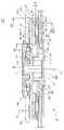
図1は、本発明のモータの実施例を示す断面図である。
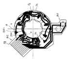
図2は、本発明のモータの実施例における平板コイルの配置と基板形状とを説明するための平面図である。
図3は、本発明のモータの実施例における基板の配線パターンを説明するための図である。
図4は、本発明のモータの実施例における要部を説明するための断面図である。An embodiment of the present invention will be described with reference to FIGS.
FIG. 1 is a sectional view showing an embodiment of the motor of the present invention.
FIG. 2 is a plan view for explaining the arrangement of the flat coil and the substrate shape in the embodiment of the motor of the present invention.
FIG. 3 is a view for explaining the wiring pattern of the substrate in the embodiment of the motor of the present invention.
FIG. 4 is a cross-sectional view for explaining a main part in the embodiment of the motor of the present invention.
図1において、このモータ50は、ロータRにディスクを保持するディスククランプ部DKを備え、そのロータR側に固定されたシャフト7を、ステータS側に固定された軸受RB,SBにより支持して、ロータRがステータSに対して回転自在としてなる構成とされている。
さらに具体的には、ステータS側に、円弧状に配列した複数の平板コイル4を設け、ロータR側に、その平板コイル4を軸方向に挟むように配置したリング状のマグネット9及び軟磁性体のプレート10を設けて、いわゆる平板コアレス構造にして成るものである。In FIG. 1, the
More specifically, a plurality of flat-
まず、ステータS側の構成について説明する。
ステータSは、モータベース1と、このモータベース1に固定された軸受ホルダ2及び多層構造の基板3と、を備えている。First, the configuration on the stator S side will be described.
The stator S includes a
モータベース1は、金属の板材をプレス加工することで形成されており、直径D4なる円形に凹む段部1aと、この段部1aと同軸の貫通孔1bと、が設けられている。
貫通孔1bには、フランジ部2aと円環部2bとを有して概ねリング状に形成された軸受ホルダ2が嵌着されている。例えば、この軸受ホルダ2は、環状の溝2kを図1の下方から押し広げてかしめによりモータベース1の貫通孔1bに固定する。The
The through-hole 1b is fitted with a bearing holder 2 having a
軸受ホルダ2における円環部2bの内周面には、円環状のラジアル軸受RBが固定されている。
この実施例において、ラジアル軸受RBは焼結含油軸受であるが、これに限るものではない。An annular radial bearing RB is fixed to the inner peripheral surface of the
In this embodiment, the radial bearing RB is a sintered oil-impregnated bearing, but is not limited thereto.
また、軸受ホルダ2における円環部2bの一端部側は、スラストプレート5及びシールプレート6により封止されている。
スラストプレート5は、シャフト7の一先端部が当接してロータRをスラスト方向に支持するスラスト軸受SBとして機能する。Further, one end portion side of the
The
一方、モータベース1の段部1aの外側には、基板3が固定されている。
この基板3は、複数層の多層基板として形成されており、この実施例においては4層の配線層を有する多層基板である。On the other hand, the
The
更に詳細を、図4(a)を用いて説明する。
この基板3は、平板コイル4側の1層を外層3aと称し、他の3層を基層3bと称する。
外層3aは、外側から、絶縁層3a1,導体層3a2,基材3a3が積層された層である。
基層3bは、導体層と基材との組み合わせを1層として合計3層を有している。
具体的には、外側から、導体層3b1,基材3b2,導体層3b3,基材3b4,導体層3b5,絶縁層3b6からなる。Further details will be described with reference to FIG.
In the
The outer layer 3a is a layer in which an insulating layer 3a1, a conductor layer 3a2, and a base material 3a3 are laminated from the outside.
The base layer 3b has a total of three layers with one combination of the conductor layer and the base material.
Specifically, it consists of the conductor layer 3b1, the substrate 3b2, the conductor layer 3b3, the substrate 3b4, the conductor layer 3b5, and the insulating layer 3b6 from the outside.
従って、この基板3は、斜線で示す4つの導体層3a2,3b1,3b3,3b5がそれぞれ独立して積層され、各導体層は、部品配置層(3a2),配線ジャンパー層(3b1),電源供給用のVcc層(3b3),不要輻射防止用のGND層(3b5)として形成されている。 Accordingly, the
また、この図には記載していないが、平板コイル4が搭載される範囲以外の部分には、このモータ50の駆動と制御のためのICなどの電子部品が搭載されている。 Although not shown in this figure, electronic parts such as an IC for driving and controlling the
このような構成の基板3において、外層3a及び基層3bの厚さT1,T2は、例えばそれぞれ、T1=0.15mm,T2=0.8mmとして形成されている。 In the
そして、この基板3は、その平面図である図2にも示されるように、外層3aについては回転軸CLを中心とする直径D1なる開口孔3eを有し、基層3bについては回転軸CLを中心とする直径D1より大径の直径D2なる開口孔3fを有して形成されている。
具体的に説明すると、直径D1は、円弧状に配列された平板コイル4の内接円の直径D3より大径とされ、直径D2は、モータベース1に形成された段部1aの内径である直径D4とほぼ同径とされている。As shown in FIG. 2, which is a plan view of the
More specifically, the diameter D1 is larger than the diameter D3 of the inscribed circle of the
図2においては、上述したように、複数の平板コイル4は、回転軸CLを中心として円弧状に外層3a上に配列固定されている。
この実施例においては、48度の等角度ピッチPで6つの平板コイル4が固定されている。In FIG. 2, as described above, the plurality of
In this embodiment, six
また、基板3の外層3aには、図3に黒太線で示すような配線パターン14が形成されており、この配線パターン14と各平板コイル4(図3では破線で示す)における巻き始め線及び巻き終わり線とが所定の接続位置にて半田により接続されている。
例えば、図2に示す一つの平板コイル4−1において、巻き始め線は、接続部3k1にて半田により基板3の外層3aにおける導体層3a2と、その導体層3a2に設けられたランド14k1を介して接続され、巻き終わり線は、接続部3k2にて半田により同じく導体層3a2と、その導体層3a2に設けられたランド14k2を介して接続されている。他の平板コイル4についても同様である。Further, a
For example, in one flat coil 4-1 shown in FIG. 2, the winding start line is connected via the conductor layer 3a2 in the outer layer 3a of the
さらに、この配線パターン14が接続された端子部3gと外部機器とが電気的に接続され、外部から各平板コイル4に対して所定の切換タイミングで通電が行われる。
この切換タイミングを得るために、ロータR側のマグネット9からの磁束を検出するセンサであるホール素子13が、外層3a上の平板コイル4の配設されていない角度範囲θ内に3つ取り付けられている。Further, the
In order to obtain this switching timing, three
基板3は、その外径が、必要な電子部品(例えばスイッチ)15の配置スペースや端子部3gを設ける為に外側に延出する部分3h1,3h2を除き、円弧状に配設された複数の平板コイル4の外接円とほぼ同じ直径D5なる外周部3jを有して形成されている。 The
次に、ロータR側の構成について説明する。
ロータRは、円板状の基部8a及びその中心部に突出して形成された円環部8bを有するロータヨーク8と、基部8aのステータ側の面8a1における外周側に固着されたリング状のマグネット9と、面8a1における内周側に固着されたリングスペーサ11と、このリングスペーサ11に固定されステータS側に設けられた平板コイル4をマグネット9との間に所定の間隙を有して挟み込むプレート10と、ロータヨーク8の円環部8bを内挿して基部8aの他面側に設けられたクランプ部10と、を備えている。Next, the configuration on the rotor R side will be described.
The rotor R includes a
ロータヨーク8は、軟磁性体である鉄の板金をプレス加工して形成されており、その円環部8の内周面にはシャフト7が圧入固定されている。
ロータヨーク8の基部8aの外周縁には、軸方向に立ち上げられたフランジ部8cが設けられている。
また、その基部8aにおける径方向の中程には、周方向に等角度間隔で複数の貫通孔8dが設けられている。The
A flange portion 8c raised in the axial direction is provided on the outer peripheral edge of the
A plurality of through-
リング状のマグネット9は、その外周面9aが、ロータヨーク8のフランジ部8cの内周面8c1と当接するように一面8a1に外周側に固定されている。
このマグネット9は、円周方向に多極に着磁されており、平板コイル4の一面(図1の上側の面)と、所定の間隙d1を有して対向するように設けられている。The ring-shaped
The
また、ロータヨーク8の一面8a1の内周側には、リング状のスペーサ11が例えば接着剤により固着されている。
このスペーサ11の一端面11s1には、ロータヨーク8に形成された貫通孔8dと嵌合する突起部11aが設けられており、この突起11aと貫通孔8dとの嵌合により、スペーサ11は、ロータヨーク8に対して良好に位置決めされる。Further, a ring-shaped spacer 11 is fixed to the inner peripheral side of the one surface 8a1 of the
One end surface 11s1 of the spacer 11 is provided with a
スペーサ11の他端面11s2側には、その外周側よりも厚さが薄くなるように段部11bが形成されている。
このスペーサ11は、これに固定されるプレート10の回転軸CL方向の精度良い位置決めをするために設けられている。A step portion 11b is formed on the other end surface 11s2 side of the spacer 11 so as to be thinner than the outer peripheral side thereof.
The spacer 11 is provided to accurately position the
プレート10は、段部10aが形成されて図1に示す断面においてクランク状を呈し、その内周部側がスペーサ11に固定され、中央部付近から外周部側が平板コイル4を支持する基板3の外層3aと所定の間隙d2を有して対向するように設けられている。
また、内周部側を段部10aにより断面クランク状とすることで、軸受ホルダ2と軸方向に非干渉としてこのモータ50の回転軸CL方向の厚さが大きくなることを回避している。The
Further, the stepped
ロータヨーク8の基部8aにおける他面8a2には、ゴムやフェルトなどにより形成されディスクDcを載置した際にこのディスクDcに当接する当接シート12が貼着されている。
この当接シート12に載置されたディスクDcは、同時に、周知構造のディスククランプ部DKにより軸方向に挟持され、このモータ50に保持される。On the other surface 8a2 of the
The disk Dc placed on the
以上詳述した実施例によれば、基板3の基層3bに開口部3fを設けることにより、基板3における磁気回路に対応する範囲、すなわち、少なくともプレート10と平板コイル4とが対向する範囲における基板3の層数を他の範囲より少なくしている。この実施例においては、外層3a、つまり1層分としている。 According to the embodiment described in detail above, by providing the
ここで、平板コイル4と外層3aとは、互いが接触する面のほぼ全面を接着剤により接着固定してあり、これによって剛性を両部材が補完し合って充分な剛性及び強度が得られ、動作や特性上で支障となるそりや傾きが生じることもない。 Here, the
また、基板3は、モータベース1に対して全層(外層3a及び基層3b)を有する部分(直径D4以上となる範囲)で固定されている。
従って、基板3はモータベース1に強固に固定されると共に、その固定された部分が多層化されているので、高密度な実装や配線パターンの引き回しが可能である。In addition, the
Therefore, since the
また、基板3における磁気回路に対応した範囲において、少なくした層数に相当する厚さT2だけプレート10を平板コイル4に接近させて両者間のエアーギャップを狭くすることができるので、磁束密度が増加し、モータのトルク定数が向上する。 Further, in the range corresponding to the magnetic circuit on the
また、このようにプレート10を平板コイル4により接近させることができるので、モータ50の軸方向長さ(厚さ)をより小さく(薄く)することができる。
このように、プレート10と平板コイル4とが対向する範囲について、開口部3fが設けられて基板3の層数が少なくなっていれば、直径D2と直径D4とが異なる径であってももちろんよい。Further, since the
As described above, as long as the
本発明のモータは、上述した実施例に対して、外層3aを、多層基板の最外側の層ではなく、基体3d上に重ねて設けたフレキシブル基板(以下、FPCとも称する)3cとした変形例であってもよい。このFPC3cの材料としては、ポリイミド樹脂などの周知の材料を用いることができる。 The motor of the present invention is a modified example in which the outer layer 3a is a flexible substrate (hereinafter also referred to as FPC) 3c provided on the
この具体的構成を、図4(b)を用いて説明する。
この基板23は、上述したように、基体3dにフレキシブル基板3cを重ねて設けた構成とされている。
基体3dは、基材3d3と、この両面に形成された導体層3d2,3d4と、さらにこれらの導体層3d2,3d4上の外側に形成された絶縁層3d1,3d5と、を有する両面基板である。This specific configuration will be described with reference to FIG.
As described above, the
The
フレキシブル基板3cは、ベース3c3,銅箔3c2及びカバーフィルム3c3が積層されて成り、基体3dの絶縁層3d1とフレキシブル基板3cのベース3c3とが貼り合わされて一体となっている。 The flexible substrate 3c is formed by laminating a base 3c3, a copper foil 3c2, and a cover film 3c3, and the insulating layer 3d1 of the
この構成において、銅箔3c2はモータ部品配置層として、また、導体層3d2はモータ駆動用電子部品配置層として、また導体層3d4は配線ジャンパー層と不要輻射防止用のGND層としてそれぞれ形成されている。 In this configuration, the copper foil 3c2 is formed as a motor component arrangement layer, the conductor layer 3d2 is formed as a motor drive electronic component arrangement layer, and the conductor layer 3d4 is formed as a wiring jumper layer and an unnecessary radiation prevention GND layer. Yes.
この変形例においては、磁気回路に対応する範囲である平板コイル4とプレート10とが対向する範囲を含んで基板23の基体3dが開口するように開口部23fを設け〔図4(b)参照〕、FPC3cのみが磁気回路中に存在するようにしている。また、この図4(b)においては、図1と同様に、開口部3fの内径(直径)D2をモータベース1の段部1aの内径(直径)D4とほぼ同径としている。
この変形例においても、プレート10と平板コイル4とが対向する範囲について、開口部3fが設けられて基板23の層数が少なくなっていれば、直径D2と直径D4とが異なる径であってももちろんよい。
このFPC3cの厚さは、0.05mm〜0.1mm程度であるので更なる薄型化が可能であり、また、上述したように、平板コイル4と接触する面の全面で接着固定されるので、互いに補完して強度を確保することができ、実施例と同様の効果を得ることができる。In this modification, an opening 23f is provided so as to open the
Also in this modified example, if the
Since the thickness of this FPC 3c is about 0.05 mm to 0.1 mm, further thinning is possible, and as described above, since it is adhesively fixed over the entire surface in contact with the
上述した実施例及び変形例において、外層3a(又はFPC3c)における開口部3eの直径D1は、円弧状に配設された複数の平板コイル4の内接円の直径D3と同等であってももちろんよく、各平板コイル4を外層3a(又はFPC3c)に接着固定した際に所望の強度を有し、平板コイル4の引き出し線と配線パターン14との半田付けが可能なスペーやレイアウトが得られるように設定すればよい。 In the embodiment and the modification described above, the diameter D1 of the
以上詳述した構成によれば、平板コイル4の外周側だけでなく、内周側にも基板3(変形例の場合はFPCを含む)と重なる範囲があるので、平板コイル4と基板3との間の電気的接続場所を自由に設定することができ、平板コイル4への給電構造に対する制約は生じ難い。
また、ロータR側のマグネット8の磁束を検知するホール素子などのセンサ13を取り付ける場所が基板3上に確保されるので、部品レイアウトに対する制約は生じ難い。
また、平板コイル4の保持強度は充分に確保される。
そして、このような種々の効果と共に薄型化が可能であるという効果を奏する。According to the configuration described in detail above, there is a range that overlaps not only the outer peripheral side of the
In addition, since a place where the
Further, the holding strength of the
And there exists an effect that thickness reduction is possible with such various effects.
本発明の実施例は、上述した構成及び手順に限定されるものではなく、本発明の要旨を逸脱しない範囲において変形例としてもよいのは言うまでもない。 The embodiment of the present invention is not limited to the configuration and procedure described above, and it goes without saying that modifications may be made without departing from the scope of the present invention.
図1においては、3つの部材であるプレート10,平板コイル4,マグネット9を、モータベース1側から、プレート10,平板コイル4,マグネット9の順に配置し、平板コイル4を固定する基板3,23をプレート10と平板コイル4とで挟む構成として説明しているが、プレート10の平板コイル側の面にマグネット9を固定し、このマグネット9と平板コイル4とで基板3,23を挟む構成としてもよい。
すなわち、モータベース1側から、プレート10,マグネット9,平板コイル4の順に配置し、平板コイル4のモータベース1の反対側の面には、ロータヨーク8の一面8a1が所定間隙を有して対向する構成としてもよい。
この構成においては、層数を少なくして減少した基板3,23の厚さ範囲に、マグネット9が入り込むように配置されているので、その分モータを薄くすることができる。また、マグネット9を、層数を少なくした分だけ平板コイルに接近させることができるので、両者間のエアーギャップがより狭くなり、磁束密度が増加し、モータのトルク定数が向上する。In FIG. 1, a
That is, the
In this configuration, since the
また、多層の基板3の層数は実施例の4層に限るものではない。また、磁気回路に対応する範囲(実施例においては、平板コイル4と基板3,23を挟んでプレート10又はマグネット9とが対向する範囲)の層数は、実施例などのように1層に限るものではない。
少なくとも、基板3が他の被固定部材(実施例ではモータベース1)に固定されている範囲よりも少ない層数とされていればよい。Further, the number of layers of the
It is sufficient that the number of layers is smaller than at least the range in which the
また、変形例においても、磁気回路に対応する範囲中にFPC3cのみを存在させるものに限らず、基板23を多層として、その内のいくつかの層をFPC3c共に存在させてもよい。少なくとも、FPC3c含めて多層とされた基板23が他の被固定部材(実施例ではモータベース1)に固定されている範囲よりも少ない層数とされていればよい。 Also, in the modified example, not only the FPC 3c only exists in the range corresponding to the magnetic circuit, but the
1 モータベース
1a 段部
1b 貫通孔
2 軸受ホルダ
2a フランジ部
2b 円環部
2k 溝
3,23 基板
3a 外層
3b 基層
3c フレキシブル基板(FPC)
3d 基体
3e,3f 開口部
3g 端子部
3k1,3k2 接続部
4 平板コイル
5 スラストプレート
6 シールプレート
7 シャフト
8 ロータヨーク
8a 基部
8a1 一面
8b 円環部
8c フランジ部
8c1 内周面
8d 貫通孔
9 マグネット
10 プレート
11 リングスペーサ
11a 突起
11s1 一端面
11s2 他端面
12 当接シート
13 センサ(ホール素子)
14 配線パターン
50 モータ
CL (回転)軸
d1,d2 間隙
Dc ディスク
D1〜D5 直径
DK ディスククランプ部
RB ラジアル軸受
SB スラスト軸受DESCRIPTION OF
14
Claims (3)
Translated fromJapanese回転軸に直交して前記モータベースに固定された基板と、
該基板の一面上に、前記回転軸を中心とする円弧状にて配列固定された複数の平板コイルと、
該複数の平板コイル及び前記基板を挟むように前記回転軸方向に配設されたプレート及び環状のマグネットと、を有し、
前記複数の平板コイルに対して、前記回転軸回りに前記プレート及び環状のマグネットが相対的に回転する構成とされて成り、
前記基板は、2以上の層数を有する多層基板であると共に、前記モータベースに固定されている範囲の層数よりも、前記複数の平板コイルと、該平板コイルとの間に前記基板を挟む前記プレート又は前記マグネットとが前記回転軸方向に重なる範囲の層数を少なくされて成ることを特徴とするモータ。A motor base;
A substrate fixed to the motor base perpendicular to the rotation axis;
On one surface of the substrate, a plurality of plate coils arranged and fixed in an arc shape centering on the rotation axis;
A plate and an annular magnet disposed in the direction of the rotation axis so as to sandwich the plurality of plate coils and the substrate,
The plate and the annular magnet are relatively rotated around the rotation axis with respect to the plurality of flat plate coils.
The substrate is a multilayer substrate having two or more layers, and the substrate is sandwiched between the plurality of plate coils and the plate coils, rather than the number of layers fixed to the motor base. A motor having a reduced number of layers in a range where the plate or the magnet overlaps in the rotation axis direction.
一面が前記モータベースに固定されると共に、他面側にフレキシブル基板が接合されて成るコア基板と、
該フレキシブル基板上に、前記回転軸を中心とする円弧状にて配列固定された複数の平板コイルと、
該複数の平板コイル及び前記フレキシブル基板を挟むように前記回転軸方向に配設されたプレート及び環状のマグネットと、を有し、
前記複数の平板コイルに対して、前記回転軸回りに前記プレート及び環状のマグネットが相対的に回転する構成とされて成り、
前記コア基板は、前記複数の平板コイルと、該平板コイルとの間に前記フレキシブル基板を挟む前記プレート又は前記マグネットとが前記回転軸方向に重なる範囲を含んで開口する開口部を有して成ることを特徴とするモータ。A motor base;
A core substrate having one surface fixed to the motor base and a flexible substrate bonded to the other surface;
On the flexible substrate, a plurality of flat coils arranged and fixed in an arc shape centered on the rotation axis;
A plate and an annular magnet disposed in the direction of the rotation axis so as to sandwich the plurality of plate coils and the flexible substrate;
The plate and the annular magnet are relatively rotated around the rotation axis with respect to the plurality of flat plate coils.
The core substrate has an opening that includes the plurality of plate coils and an opening including a range where the plate or the magnet sandwiching the flexible substrate between the plate coils overlaps in the rotation axis direction. A motor characterized by that.
一面が前記モータベースに固定されると共に、他面側にフレキシブル基板が接合されて成るコア基板と、
前記フレキシブル基板上に、前記回転軸を中心とする円弧状にて配列固定された複数の平板コイルと、
該複数の平板コイル及び前記フレキシブル基板を挟むように前記回転軸方向に配設されたプレート及び環状のマグネットと、を有し、
前記複数の平板コイルに対して、前記回転軸回りに前記プレート及び環状のマグネットが相対的に回転する構成とされて成り、
前記コア基板は、2以上の層数を有する多層基板であると共に、前記モータベースに固定されている範囲の層数よりも、前記複数の平板コイルと、該平板コイルとの間に前記フレキシブル基板を挟む前記プレート又は前記マグネットとが前記回転軸方向に重なる範囲の層数を少なくされて成ることを特徴とするモータ。A motor base;
A core substrate having one surface fixed to the motor base and a flexible substrate bonded to the other surface;
On the flexible substrate, a plurality of flat coils arranged and fixed in an arc shape centered on the rotation axis,
A plate and an annular magnet disposed in the direction of the rotation axis so as to sandwich the plurality of plate coils and the flexible substrate;
The plate and the annular magnet are relatively rotated around the rotation axis with respect to the plurality of flat plate coils.
The core substrate is a multilayer substrate having two or more layers, and the flexible substrate is located between the plurality of plate coils and the plate coils, rather than the number of layers in a range fixed to the motor base. A motor having a reduced number of layers in a range where the plate or the magnet sandwiching the substrate overlaps in the rotation axis direction.
Priority Applications (1)
| Application Number | Priority Date | Filing Date | Title |
|---|---|---|---|
| JP2006177708AJP2008011611A (en) | 2006-06-28 | 2006-06-28 | Electric motor |
Applications Claiming Priority (1)
| Application Number | Priority Date | Filing Date | Title |
|---|---|---|---|
| JP2006177708AJP2008011611A (en) | 2006-06-28 | 2006-06-28 | Electric motor |
Publications (1)
| Publication Number | Publication Date |
|---|---|
| JP2008011611Atrue JP2008011611A (en) | 2008-01-17 |
Family
ID=39069287
Family Applications (1)
| Application Number | Title | Priority Date | Filing Date |
|---|---|---|---|
| JP2006177708APendingJP2008011611A (en) | 2006-06-28 | 2006-06-28 | Electric motor |
Country Status (1)
| Country | Link |
|---|---|
| JP (1) | JP2008011611A (en) |
Cited By (22)
| Publication number | Priority date | Publication date | Assignee | Title |
|---|---|---|---|---|
| JP2012205349A (en)* | 2011-03-24 | 2012-10-22 | Ntn Corp | Rotary drive device and centrifugal pump device using the same |
| WO2013079502A1 (en)* | 2011-11-29 | 2013-06-06 | Leibniz-Institut Für Festkörper- Und Werkstoffforschung Dresden E.V. | Use of flexible magnetic thin layer sensor elements |
| US9109601B2 (en) | 2008-06-23 | 2015-08-18 | Thoratec Corporation | Blood pump apparatus |
| US9133854B2 (en) | 2010-03-26 | 2015-09-15 | Thoratec Corporation | Centrifugal blood pump device |
| US9132215B2 (en) | 2010-02-16 | 2015-09-15 | Thoratee Corporation | Centrifugal pump apparatus |
| US9382908B2 (en) | 2010-09-14 | 2016-07-05 | Thoratec Corporation | Centrifugal pump apparatus |
| US9381285B2 (en) | 2009-03-05 | 2016-07-05 | Thoratec Corporation | Centrifugal pump apparatus |
| US9410549B2 (en) | 2009-03-06 | 2016-08-09 | Thoratec Corporation | Centrifugal pump apparatus |
| US9556873B2 (en) | 2013-02-27 | 2017-01-31 | Tc1 Llc | Startup sequence for centrifugal pump with levitated impeller |
| US9623161B2 (en) | 2014-08-26 | 2017-04-18 | Tc1 Llc | Blood pump and method of suction detection |
| US9709061B2 (en) | 2013-01-24 | 2017-07-18 | Tc1 Llc | Impeller position compensation using field oriented control |
| US9713663B2 (en) | 2013-04-30 | 2017-07-25 | Tc1 Llc | Cardiac pump with speed adapted for ventricle unloading |
| US9850906B2 (en) | 2011-03-28 | 2017-12-26 | Tc1 Llc | Rotation drive device and centrifugal pump apparatus employing same |
| KR101840589B1 (en) | 2016-06-03 | 2018-03-20 | 연세대학교 산학협력단 | Composition for preventing or treating corneal dystrophy |
| US10052420B2 (en) | 2013-04-30 | 2018-08-21 | Tc1 Llc | Heart beat identification and pump speed synchronization |
| US10117983B2 (en) | 2015-11-16 | 2018-11-06 | Tc1 Llc | Pressure/flow characteristic modification of a centrifugal pump in a ventricular assist device |
| US10166318B2 (en) | 2015-02-12 | 2019-01-01 | Tc1 Llc | System and method for controlling the position of a levitated rotor |
| US10245361B2 (en) | 2015-02-13 | 2019-04-02 | Tc1 Llc | Impeller suspension mechanism for heart pump |
| CN109845075A (en)* | 2016-10-28 | 2019-06-04 | 伟摩有限责任公司 | Apparatus and method for driving a rotating platform |
| US10371152B2 (en) | 2015-02-12 | 2019-08-06 | Tc1 Llc | Alternating pump gaps |
| US10506935B2 (en) | 2015-02-11 | 2019-12-17 | Tc1 Llc | Heart beat identification and pump speed synchronization |
| US11909263B1 (en) | 2016-10-19 | 2024-02-20 | Waymo Llc | Planar rotary transformer |
- 2006
- 2006-06-28JPJP2006177708Apatent/JP2008011611A/enactivePending
Cited By (39)
| Publication number | Priority date | Publication date | Assignee | Title |
|---|---|---|---|---|
| US9109601B2 (en) | 2008-06-23 | 2015-08-18 | Thoratec Corporation | Blood pump apparatus |
| US9381285B2 (en) | 2009-03-05 | 2016-07-05 | Thoratec Corporation | Centrifugal pump apparatus |
| US9410549B2 (en) | 2009-03-06 | 2016-08-09 | Thoratec Corporation | Centrifugal pump apparatus |
| US9132215B2 (en) | 2010-02-16 | 2015-09-15 | Thoratee Corporation | Centrifugal pump apparatus |
| US9133854B2 (en) | 2010-03-26 | 2015-09-15 | Thoratec Corporation | Centrifugal blood pump device |
| US9638202B2 (en) | 2010-09-14 | 2017-05-02 | Tc1 Llc | Centrifugal pump apparatus |
| US9382908B2 (en) | 2010-09-14 | 2016-07-05 | Thoratec Corporation | Centrifugal pump apparatus |
| JP2012205349A (en)* | 2011-03-24 | 2012-10-22 | Ntn Corp | Rotary drive device and centrifugal pump device using the same |
| US9850906B2 (en) | 2011-03-28 | 2017-12-26 | Tc1 Llc | Rotation drive device and centrifugal pump apparatus employing same |
| WO2013079502A1 (en)* | 2011-11-29 | 2013-06-06 | Leibniz-Institut Für Festkörper- Und Werkstoffforschung Dresden E.V. | Use of flexible magnetic thin layer sensor elements |
| US9709061B2 (en) | 2013-01-24 | 2017-07-18 | Tc1 Llc | Impeller position compensation using field oriented control |
| US9556873B2 (en) | 2013-02-27 | 2017-01-31 | Tc1 Llc | Startup sequence for centrifugal pump with levitated impeller |
| US9713663B2 (en) | 2013-04-30 | 2017-07-25 | Tc1 Llc | Cardiac pump with speed adapted for ventricle unloading |
| US12343517B2 (en) | 2013-04-30 | 2025-07-01 | Tc1 Llc | Cardiac pump with speed adapted for ventricle unloading |
| US10052420B2 (en) | 2013-04-30 | 2018-08-21 | Tc1 Llc | Heart beat identification and pump speed synchronization |
| US10980928B2 (en) | 2013-04-30 | 2021-04-20 | Tc1 Llc | Cardiac pump with speed adapted for ventricle unloading |
| US11724094B2 (en) | 2013-04-30 | 2023-08-15 | Tc1 Llc | Cardiac pump with speed adapted for ventricle unloading |
| US9623161B2 (en) | 2014-08-26 | 2017-04-18 | Tc1 Llc | Blood pump and method of suction detection |
| US10856748B2 (en) | 2015-02-11 | 2020-12-08 | Tc1 Llc | Heart beat identification and pump speed synchronization |
| US11712167B2 (en) | 2015-02-11 | 2023-08-01 | Tc1 Llc | Heart beat identification and pump speed synchronization |
| US12213766B2 (en) | 2015-02-11 | 2025-02-04 | Tc1 Llc | Heart beat identification and pump speed synchronization |
| US10506935B2 (en) | 2015-02-11 | 2019-12-17 | Tc1 Llc | Heart beat identification and pump speed synchronization |
| US11015605B2 (en) | 2015-02-12 | 2021-05-25 | Tc1 Llc | Alternating pump gaps |
| US11724097B2 (en) | 2015-02-12 | 2023-08-15 | Tc1 Llc | System and method for controlling the position of a levitated rotor |
| US10874782B2 (en) | 2015-02-12 | 2020-12-29 | Tc1 Llc | System and method for controlling the position of a levitated rotor |
| US12297836B2 (en) | 2015-02-12 | 2025-05-13 | Tc1 Llc | Alternating pump gaps |
| US10371152B2 (en) | 2015-02-12 | 2019-08-06 | Tc1 Llc | Alternating pump gaps |
| US12285598B2 (en) | 2015-02-12 | 2025-04-29 | Tc1 Llc | System and method for controlling the position of a levitated rotor |
| US11781551B2 (en) | 2015-02-12 | 2023-10-10 | Tc1 Llc | Alternating pump gaps |
| US10166318B2 (en) | 2015-02-12 | 2019-01-01 | Tc1 Llc | System and method for controlling the position of a levitated rotor |
| US10245361B2 (en) | 2015-02-13 | 2019-04-02 | Tc1 Llc | Impeller suspension mechanism for heart pump |
| US10117983B2 (en) | 2015-11-16 | 2018-11-06 | Tc1 Llc | Pressure/flow characteristic modification of a centrifugal pump in a ventricular assist device |
| US11639722B2 (en) | 2015-11-16 | 2023-05-02 | Tc1 Llc | Pressure/flow characteristic modification of a centrifugal pump in a ventricular assist device |
| US10888645B2 (en) | 2015-11-16 | 2021-01-12 | Tc1 Llc | Pressure/flow characteristic modification of a centrifugal pump in a ventricular assist device |
| KR101840589B1 (en) | 2016-06-03 | 2018-03-20 | 연세대학교 산학협력단 | Composition for preventing or treating corneal dystrophy |
| US11909263B1 (en) | 2016-10-19 | 2024-02-20 | Waymo Llc | Planar rotary transformer |
| CN109845075B (en)* | 2016-10-28 | 2021-11-02 | 伟摩有限责任公司 | Apparatus and method for driving a rotating platform |
| JP2020503824A (en)* | 2016-10-28 | 2020-01-30 | ウェイモ エルエルシー | Apparatus and method for driving a rotary platform |
| CN109845075A (en)* | 2016-10-28 | 2019-06-04 | 伟摩有限责任公司 | Apparatus and method for driving a rotating platform |
Similar Documents
| Publication | Publication Date | Title |
|---|---|---|
| JP2008011611A (en) | Electric motor | |
| JP5181232B2 (en) | STATOR, MOTOR, RECORDING MEDIUM DRIVE DEVICE, AND STATOR MANUFACTURING METHOD | |
| US9502071B2 (en) | Spindle motor and disk drive apparatus | |
| JP2008312356A (en) | Circuit board and brushless motor using circuit board | |
| US8699180B2 (en) | Motor and disk drive apparatus | |
| CN103915928A (en) | Motor and disk drive apparatus | |
| JP2020120430A (en) | Rotary table device | |
| US8593759B1 (en) | Spindle motor and disk drive apparatus | |
| CN101521421B (en) | Motor and disk drive apparatus | |
| JP2007037393A (en) | Spindle motor and recording disc driving device mounted with the same | |
| US20140153132A1 (en) | Spindle motor and disk drive apparatus | |
| US6781795B2 (en) | Connector for flexible printed circuit boards, head actuator provided with the same, and disk drive | |
| JP2021087279A (en) | Spindle motor and hard disk drive device | |
| JP5963392B2 (en) | motor | |
| US8643978B1 (en) | Spindle motor and disk drive apparatus | |
| JP2004032926A (en) | Disk drive | |
| JP5015825B2 (en) | Disk drive | |
| JP2004032829A (en) | Magnetic disk drive | |
| JP2006238666A (en) | Spindle motor, recording disk drive using the same, and spindle motor manufacturing method | |
| JP2009207277A (en) | Compact motor | |
| JP2016082815A (en) | Motor device | |
| KR101216845B1 (en) | spindle motor | |
| JP5899649B2 (en) | Motor and disk drive device | |
| JP2009268166A (en) | Spindle motor and disk drive device | |
| JP2009050090A (en) | Brushless motor equipped with chucking device, and the brushless motor |
Legal Events
| Date | Code | Title | Description |
|---|---|---|---|
| A711 | Notification of change in applicant | Free format text:JAPANESE INTERMEDIATE CODE: A711 Effective date:20080401 | |
| RD02 | Notification of acceptance of power of attorney | Free format text:JAPANESE INTERMEDIATE CODE: A7422 Effective date:20080428 |