JP2008006082A - Drain pump for toilet - Google Patents
Drain pump for toiletDownload PDFInfo
- Publication number
- JP2008006082A JP2008006082AJP2006179790AJP2006179790AJP2008006082AJP 2008006082 AJP2008006082 AJP 2008006082AJP 2006179790 AJP2006179790 AJP 2006179790AJP 2006179790 AJP2006179790 AJP 2006179790AJP 2008006082 AJP2008006082 AJP 2008006082A
- Authority
- JP
- Japan
- Prior art keywords
- toilet
- pipe
- drain
- pump
- water
- Prior art date
- Legal status (The legal status is an assumption and is not a legal conclusion. Google has not performed a legal analysis and makes no representation as to the accuracy of the status listed.)
- Pending
Links
- XLYOFNOQVPJJNP-UHFFFAOYSA-NwaterSubstancesOXLYOFNOQVPJJNP-UHFFFAOYSA-N0.000claimsabstractdescription42
- 238000005086pumpingMethods0.000claimsabstractdescription4
- 238000010521absorption reactionMethods0.000claimsdescription7
- 238000004140cleaningMethods0.000description10
- 244000005700microbiomeSpecies0.000description4
- 239000000126substanceSubstances0.000description3
- 239000007788liquidSubstances0.000description2
- 238000000034methodMethods0.000description2
- 229920003002synthetic resinPolymers0.000description2
- 239000000057synthetic resinSubstances0.000description2
- 238000002604ultrasonographyMethods0.000description2
- 239000004698PolyethyleneSubstances0.000description1
- 230000003796beautyEffects0.000description1
- 230000008602contractionEffects0.000description1
- 230000000694effectsEffects0.000description1
- 230000003203everyday effectEffects0.000description1
- 238000011010flushing procedureMethods0.000description1
- 238000003780insertionMethods0.000description1
- 230000037431insertionEffects0.000description1
- -1polyethylenePolymers0.000description1
- 229920000573polyethylenePolymers0.000description1
- 238000007790scrapingMethods0.000description1
- 230000000087stabilizing effectEffects0.000description1
- 239000004094surface-active agentSubstances0.000description1
Images


Landscapes
- Non-Flushing Toilets (AREA)
- Sanitary Device For Flush Toilet (AREA)
- Reciprocating Pumps (AREA)
Abstract
Description
Translated fromJapanese本発明は、ポンプとくに便器用排水ポンプに関するものである。 The present invention relates to a pump, particularly a toilet drain pump.
下水道の整備により水洗式のトイレが普及してきている。
図1は、いわゆる洋式便器(以下、単に便器という)を概略的に示す断面図である。
この断面図に示すように、便器20のボール部22面には常に水が溜まった状態であり、掃除を怠ると、便器20の喫水面近傍やボール内面に汚れが付着し、不衛生になるとともに見た目も悪くなる。また、それだけではなく悪臭を放つようになる。
そのため、便器20の汚れを取り除き衛生的な状態を保つため頻繁に清掃を行うことが必要である。Flush toilets have become popular due to the development of sewers.
FIG. 1 is a cross-sectional view schematically showing a so-called Western-style toilet (hereinafter simply referred to as a toilet).
As shown in this cross-sectional view, water is always accumulated on the surface of the
Therefore, it is necessary to frequently clean the
清掃は汚れをブラシで擦り落としたり高圧水で流して行うが、毎日行うには手間がかかり煩雑である。とくに便器のボール面は常に水が溜まっているため掃除がし難いという問題がある。また、ボール部に清掃用の薬剤をいれても溜まった水で希釈され清掃効果が低減し、大量の薬剤が必要であるなどの問題がある。そこで、溜まった水を除去することも考えられるが、実際に除去するには、例えば、雑巾などを用いて水を吸い取らせるが、便器に溜まった水の中に手を入れるのは抵抗感がありかつ排水に手間が掛かるという問題がある。 Cleaning is carried out by scraping off dirt with a brush or flushing with high-pressure water, but it is troublesome and complicated every day. In particular, the ball surface of the toilet bowl has a problem that it is difficult to clean because the water is always collected. In addition, even if a cleaning chemical is put in the ball part, it is diluted with the accumulated water and the cleaning effect is reduced, and a large amount of chemical is required. Therefore, it is conceivable to remove the accumulated water, but in order to actually remove it, for example, a rag is used to absorb the water, but it is uncomfortable to put your hands in the water collected in the toilet bowl. There is a problem that it takes time to drain the water.
そこで便器の掃除の手間を少なくするため、便器についた汚れを効率よく容易に除去するため、便器に付着した汚れに超音波を照射して除去するものが知られている(特許文献1)。
これは、便器に液体を張って超音波で液体に振動を付与するか、空中で汚染部に超音波を照射するか、或いは、汚染部に直接超音波振動子を作用させるものである。
この装置は便器の汚れを超音波で除去するものであるが、これとは別に、便器のボール部分に溜まっている水の中の微生物に着目して、超音波で微生物の繁殖を抑え或いは殺菌して、微生物の繁殖に伴う汚れ付着を長期に渡って抑制し、便器のボール部の清掃を頻繁に行わなくとも衛生的な状態が保てるようにした水洗便所も提案されている(特許文献2)。
しかしながら、一般家庭でこれらの装置を備えるにはコストが掛かり手軽に利用できないという問題がある。Therefore, in order to reduce the trouble of cleaning the toilet bowl, in order to efficiently and easily remove the dirt on the toilet bowl, a technique is known in which dirt attached to the toilet bowl is irradiated with ultrasonic waves (Patent Document 1).
In this method, a liquid is applied to the toilet and vibration is applied to the liquid with ultrasonic waves, or the contaminated part is irradiated with ultrasonic waves in the air, or an ultrasonic vibrator is directly applied to the contaminated part.
This device removes dirt on toilet bowls with ultrasound, but apart from this, focusing on microorganisms in the water accumulated in the bowl part of the toilet bowl, the propagation of microorganisms is suppressed or sterilized with ultrasound. In addition, a flush toilet has also been proposed in which dirt adherence associated with the propagation of microorganisms is suppressed for a long period of time, and a hygienic state can be maintained without frequently cleaning the bowl portion of the toilet bowl (Patent Document 2). ).
However, there is a problem that providing these devices in a general household is costly and cannot be used easily.
本発明は、従来の便器清掃における上記のような問題に鑑みてなされたものであって、その目的は、従来の便器の清掃において問題となる、便器内に溜まった水を容易に排水できるポンプを提供することであり、コストを掛けずに、したがってどの家庭でも容易に入手でき、取り扱いが簡便な便器用排水ポンプを提供して、便器の清掃をより簡単かつ完全に行えるようにすることである。 The present invention has been made in view of the above-described problems in conventional toilet cleaning, and the purpose thereof is a pump that can easily drain water accumulated in the toilet, which is a problem in conventional toilet cleaning. By providing a toilet drainage pump that is easy to obtain and easy to handle at no cost, and therefore easy to handle, so that toilet cleaning can be done more easily and completely. is there.
請求項1の発明は、手動で水を汲み上げるポンプ部と、該ポンプ部に連結された吸水管及び可撓性を有する排水管と、該排水管を挿入する剛性ガイド管とを備えた、便器のボール部に溜まった水を排水するための便器用排水ポンプであって、前記ガイド管は、前記ボールの底に配置したときに、排水管の先端部をその先端部が便器の前壁又は後壁の裏側に配置された排水口内に配置可能な上向き湾曲形状に形成されていることを特徴とする。
請求項2の発明は、請求項1に記載された便器用排水ポンプにおいて、前記ガイド管は、少なくとも前記ボール部の底に接触する部分に排水孔又は溝が形成されていることを特徴とする。
請求項3の発明は、請求項1に記載された便器用排水ポンプにおいて、前記ガイド管は、剛性を有する網状管体で形成されていることを特徴とする。The invention of claim 1 is a toilet comprising a pump part for manually pumping water, a water absorption pipe connected to the pump part and a flexible drain pipe, and a rigid guide pipe into which the drain pipe is inserted. A toilet drainage pump for draining water accumulated in a ball portion of the bowl, wherein the guide tube is disposed at the bottom of the ball, and the tip of the drainage tube is the front wall of the toilet bowl or It is formed in the upward curved shape which can be arrange | positioned in the drain outlet arrange | positioned at the back side of a rear wall.
According to a second aspect of the present invention, in the toilet drainage pump according to the first aspect, the guide pipe has a drain hole or a groove formed at least in a portion contacting the bottom of the ball portion. .
According to a third aspect of the present invention, in the toilet drainage pump according to the first aspect, the guide tube is formed of a reticulated tubular body having rigidity.
従来の例えば家庭用の給油ポンプを用いて容易に製造でき、しかも便器のボール内の水を容易に排水することができるため、便器の清掃をより簡単かつ完全に行うことができる。また、そのコストは極めて低廉である。 Since it can be easily manufactured using a conventional oil pump for home use, and the water in the bowl of the toilet bowl can be easily drained, the toilet bowl can be cleaned more easily and completely. In addition, the cost is extremely low.
図1は、本発明の実施形態に係る便器用排水ポンプの側面図で便器内に設置した使用状態を示す図面であり、図1A及び1Bは、便器内の排水口の位置により異なる位置に設置した状態を示している。
本実施形態に係る便器用排水ポンプ10は、従来の例えば家庭用の給油ポンプと同様の構成である。即ち、伸縮操作により内部容積を変更してポンプ作用をする樽形の柔軟な手動式のポンプ部12と、該ポンプ部12から直線状に延び、便器20のボール部22に溜まった水を吸い上げる吸水管14、及び、第1の吸水管14と直交状に交わり、ポンプ部12で吸い上げた水を便器の排水口24に送り出す柔軟な、つまり可撓性のある排水管16を備えている。FIG. 1 is a side view of a toilet drainage pump according to an embodiment of the present invention showing a use state installed in a toilet. FIGS. 1A and 1B are installed at different positions depending on the position of a drain outlet in the toilet. Shows the state.
The
吸水管14は、剛性のある合成樹脂製のパイプで形成され、先端(又は下端)に吸込口15を有している。排水管16の先端は、便器20のボール部22内に溜まった水中に突入させる部分と、柔軟性のあるひだ付き管とからなっている。ポンプ部12の内部には、吸水管14側からポンプ部12を経由して排水管16側への水の送り出しのみを許容する図示しない逆止弁が設けられている。また、ポンプ部12の上部には、該ポンプ部3内を外気と連通させる空気抜きつまみ30が設けられる。
なお、前記ポンプ10は、従来の手動式の家庭用の給油ポンプと同様にポリエチレン等の合成樹脂でできている。The
The
ところで、前記ポンプ10を用いて便器20のボール部22の底に溜まった水を排水するためには、前記ポンプ10の排水管16を便器20の排水口24内に挿入する必要があるが、前記排水管16は、柔軟に構成されているからその先端部を、便器20の前壁(図1B)又は後壁(図1A)の裏側に設けられ、実際には外から隠れた排水口24中に挿入することは容易ではない。
とくに、便器20の清掃は頻繁に行われることから、従来の給油ポンプを用いて、その排水管の先端部を隠れた排水口24に差し込んで、便器20のボール部22内の水を排水することはまず不可能である。By the way, in order to drain the water accumulated on the bottom of the
In particular, since the
そこで、本実施形態では、この排水管16の形状を安定させかつその先端部の部分17(図2参照)を排水口24内に配置するためのガイド管18を用いている。即ち、排水管16をガイド管18中に挿入し、その状態でガイド管18の湾曲形状を利用して便器20の前壁又は後壁の裏側から挿入する。排水管16からの排水は排水用管路26を通って図示しない下水に流れる。
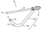
図2は、前記ポンプ10とガイド管18の分解斜視図である。図示のようにガイド管18は直線部分18aとこの直線状部分18aに続く湾曲部分18bとからなっている。排水管16をガイド管18に通した状態で、ガイド管18と排水管16を便器の前壁又は後壁の裏側から挿入する。ガイド管18の湾曲部分18bは、排水管16の先端部17を排水口24内に容易に導くことができるよう、図示のように、実際の便器20の構造に合わせて下から上に向かって湾曲した形状に形成されている。Therefore, in the present embodiment, a
FIG. 2 is an exploded perspective view of the
なお、ガイド管18の湾曲部18bを、便器の前壁又は後壁の裏側から挿入するのみで排水管16の先端部17が排水口24内に届く長さに構成すると、ガイド管18の湾曲部18bが長くなり過ぎて便器の前壁又は後壁の裏側から挿入できなくなる。そのため、ガイド管18の湾曲部18bを若干短く形成し、湾曲部18bの一部を前記便器の前壁又は後壁の裏側に差し込んだ状態で、排水管16をガイド管18に沿って排水口24に向かって押し出すようにする。
このようにすることにより、配水管を排水口24にスムーズに配置することができる。If the
By doing in this way, a water pipe can be smoothly arrange | positioned at the
図3は、前記ポンプ10の排水管16にガイド管18を装着した本願発明の実施形態に係る便器用排水ポンプの斜視図である。
この図から明らかなように、前記ポンプ10の吸水管14先端を便器20のボール部22の底に当て、かつ排水管16の先端部17を排水口24内に配置したときに、少なくともガイド管18の湾曲部18bが前記ボール部22の底面に接触する部分にはガイド管18の水抜き溝又は孔19が形成されている。FIG. 3 is a perspective view of a toilet drainage pump according to an embodiment of the present invention in which a
As is clear from this figure, when the tip of the
この水抜き溝又は孔19は、ガイド管18を前記ボール部22内に溜まった水中に入れたときに、その内部に侵入した水を排水するためのものである。この水抜き溝又は孔19の形状は自由であるが、ガイド管18に排水管16を挿入するときに、排水管16の先端部17が水抜き溝又は孔19の縁に当たって挿入時の抵抗とならないように、例えば排水管16の径に比して十分小さな径の小穴とする、或いは細い溝に形成することができる。勿論小穴(形状は任意である)を並べて複数個を形成しても、あるいは細い溝を並行に或いは非並行に複数条設けてもよい。
また、水抜き溝又は孔19を設ける代わりに、ガイド管18の形状が維持できるものであれば、全体が網状の管体で形成してもよい。ガイド管18をこのように形成することにより、水はガイド管18の内外を自由に出入りすることができる。いずれにしても、ガイド管18内に侵入した水は全てこの便器用排水ポンプ10で完全に排水することができる。The drain groove or
Moreover, as long as the shape of the guide pipe |
以上のように、本実施形態に係る便器用排水ポンプ10を用いるときは、剛性のあるガイド管18の湾曲形状を利用して、ガイド管18を便器の前壁又は後壁の下端部からスムーズにその裏側に挿入することができる。それによって、ガイド管18の内部に挿通した排水管16の端部を排水口24内に容易に配置することができる。
また、排水管16は剛性のあるガイド管18によってその形状が維持されるから、排水中に誤ってポンプを動かしても、排水管16が排水口24から妄りに外れることがない。As described above, when the
In addition, since the shape of the
このように、例えば従来の家庭用給油ポンプを用いて、単にその排出側の管にガイド管18を嵌めることでこれを便器用排水ポンプに作り替えることができ、極めて低コストで便器のボールの底に溜まった水を排水することができる。
便器の排水を行った後、洗浄用化学薬品、界面活性剤又は研磨剤等を用いて便器内面及び底面をブラシ掛けするか又は水で洗浄することで便器の汚れを完全に落とし、しかも溜まった水の中の微生物も完全に除去することができるため、便器の美観だけではなくその衛生状態も長く良好に維持することができる。In this way, for example, by using a conventional household oil pump, the
After draining the toilet bowl, brush the toilet inner surface and bottom using cleaning chemicals, surfactant or abrasive, or wash with water to completely clean the toilet bowl and collect it. Since microorganisms in the water can be completely removed, not only the beauty of the toilet but also the hygienic condition can be maintained well for a long time.
10・・・便器用排水ポンプ、12・・・ポンプ部、14・・・吸水管、16・・・排水管、18・・・ガイド管、19・・・水抜き溝又は孔、20・・・便器、22・・・ボール部、24・・・排水口、26・・・排水用管路。DESCRIPTION OF
Claims (3)
Translated fromJapanese前記ガイド管は、前記ボールの底に配置したときに、排水管の先端部をその先端部が便器の前壁又は後壁の裏側に配置された排水口内に配置可能な上向き湾曲形状に形成されていることを特徴とする便器用排水ポンプ。Water collected in a bowl portion of a toilet comprising a pump section for manually pumping water, a water absorption pipe connected to the pump section and a flexible drain pipe, and a rigid guide pipe for inserting the drain pipe A toilet drain pump for draining
When the guide tube is disposed at the bottom of the ball, the distal end portion of the drainage pipe is formed in an upwardly curved shape that can be disposed in a drain outlet disposed at the back side of the front or rear wall of the toilet bowl. A toilet drainage pump characterized by
前記ガイド管は、少なくとも前記ボール部の底に接触する部分に排水孔又は溝が形成されていることを特徴とする便器用排水ポンプ。In the toilet drain pump according to claim 1,
The toilet pipe drainage pump is characterized in that a drainage hole or a groove is formed in at least a portion of the guide tube that contacts the bottom of the ball portion.
前記ガイド管は、剛性を有する網状管体で形成されていることを特徴とする便器用排水ポンプ。In the toilet drain pump according to claim 1,
The toilet pipe drainage pump is characterized in that the guide pipe is formed of a net-like pipe body having rigidity.
Priority Applications (1)
| Application Number | Priority Date | Filing Date | Title |
|---|---|---|---|
| JP2006179790AJP2008006082A (en) | 2006-06-29 | 2006-06-29 | Drain pump for toilet |
Applications Claiming Priority (1)
| Application Number | Priority Date | Filing Date | Title |
|---|---|---|---|
| JP2006179790AJP2008006082A (en) | 2006-06-29 | 2006-06-29 | Drain pump for toilet |
Publications (1)
| Publication Number | Publication Date |
|---|---|
| JP2008006082Atrue JP2008006082A (en) | 2008-01-17 |
Family
ID=39064820
Family Applications (1)
| Application Number | Title | Priority Date | Filing Date |
|---|---|---|---|
| JP2006179790APendingJP2008006082A (en) | 2006-06-29 | 2006-06-29 | Drain pump for toilet |
Country Status (1)
| Country | Link |
|---|---|
| JP (1) | JP2008006082A (en) |
Cited By (1)
| Publication number | Priority date | Publication date | Assignee | Title |
|---|---|---|---|---|
| CN103835356A (en)* | 2014-03-04 | 2014-06-04 | 陈科 | Toilet bowl with dredging device |
Citations (3)
| Publication number | Priority date | Publication date | Assignee | Title |
|---|---|---|---|---|
| JPS5916499A (en)* | 1982-07-20 | 1984-01-27 | Matsushita Electric Ind Co Ltd | microphone |
| JPH0446173A (en)* | 1990-06-12 | 1992-02-17 | Nikko Kyodo Co Ltd | Production of cyclic lactone |
| JP2000273935A (en)* | 1999-03-25 | 2000-10-03 | Inax Corp | Stagnant water elimination method for drainage trap |
- 2006
- 2006-06-29JPJP2006179790Apatent/JP2008006082A/enactivePending
Patent Citations (3)
| Publication number | Priority date | Publication date | Assignee | Title |
|---|---|---|---|---|
| JPS5916499A (en)* | 1982-07-20 | 1984-01-27 | Matsushita Electric Ind Co Ltd | microphone |
| JPH0446173A (en)* | 1990-06-12 | 1992-02-17 | Nikko Kyodo Co Ltd | Production of cyclic lactone |
| JP2000273935A (en)* | 1999-03-25 | 2000-10-03 | Inax Corp | Stagnant water elimination method for drainage trap |
Cited By (2)
| Publication number | Priority date | Publication date | Assignee | Title |
|---|---|---|---|---|
| CN103835356A (en)* | 2014-03-04 | 2014-06-04 | 陈科 | Toilet bowl with dredging device |
| CN103835356B (en)* | 2014-03-04 | 2015-01-28 | 宁波高新区科卉创意产品设计有限公司 | Toilet bowl with dredging device |
Similar Documents
| Publication | Publication Date | Title |
|---|---|---|
| JP6359493B2 (en) | Pipe communication device | |
| JP5597831B2 (en) | Drainage pipes and drainage traps for drainage equipment | |
| US20040163166A1 (en) | Plunger appliance for toilets | |
| KR20190061457A (en) | Apparatus to remove foul odor for toilet | |
| JP6537597B2 (en) | Large intestine washer | |
| JP5756938B2 (en) | Drainage pipes and drainage traps for drainage equipment | |
| JP2003328418A (en) | Drainage piping | |
| JP2007224524A (en) | Toilet bowl apparatus | |
| JP2008006082A (en) | Drain pump for toilet | |
| JP2011094359A (en) | Drain trap | |
| JP2003301491A (en) | Drainage piping | |
| CN107246056B (en) | Sanitary closestool capable of preventing sewage from splashing and using method thereof | |
| KR101277772B1 (en) | A drain trap for washstand | |
| KR200447310Y1 (en) | Bidet with odor removal | |
| KR100697254B1 (en) | Cleaning device mounted on the toilet lid | |
| KR20190137668A (en) | Device for boring clogged drain for water closet | |
| KR200361194Y1 (en) | bubble cleansing apparatus for toilet stool | |
| JP4922005B2 (en) | Aquarium cleaning tool | |
| JP2018188857A (en) | Drain trap | |
| CN207499097U (en) | squat toilet | |
| JP6693038B2 (en) | Odor removal device for toilet bowl | |
| KR200323082Y1 (en) | The Urinal with a Foothold | |
| US20140123377A1 (en) | Pipe and tubular declogging device and method of use | |
| JP2948793B2 (en) | Washing device integrated sink | |
| KR20100052972A (en) | Bidet for toilet stool |
Legal Events
| Date | Code | Title | Description |
|---|---|---|---|
| A621 | Written request for application examination | Free format text:JAPANESE INTERMEDIATE CODE: A621 Effective date:20090616 | |
| A977 | Report on retrieval | Effective date:20110216 Free format text:JAPANESE INTERMEDIATE CODE: A971007 | |
| A131 | Notification of reasons for refusal | Free format text:JAPANESE INTERMEDIATE CODE: A131 Effective date:20110428 | |
| A02 | Decision of refusal | Effective date:20110929 Free format text:JAPANESE INTERMEDIATE CODE: A02 |