JP2007537841A - Implantable biosensor system - Google Patents
Implantable biosensor systemDownload PDFInfo
- Publication number
- JP2007537841A JP2007537841AJP2007527472AJP2007527472AJP2007537841AJP 2007537841 AJP2007537841 AJP 2007537841AJP 2007527472 AJP2007527472 AJP 2007527472AJP 2007527472 AJP2007527472 AJP 2007527472AJP 2007537841 AJP2007537841 AJP 2007537841A
- Authority
- JP
- Japan
- Prior art keywords
- signal
- sensor
- receive
- generate
- data
- Prior art date
- Legal status (The legal status is an assumption and is not a legal conclusion. Google has not performed a legal analysis and makes no representation as to the accuracy of the status listed.)
- Pending
Links
- WQZGKKKJIJFFOK-GASJEMHNSA-NGlucoseNatural productsOC[C@H]1OC(O)[C@H](O)[C@@H](O)[C@@H]1OWQZGKKKJIJFFOK-GASJEMHNSA-N0.000claimsabstractdescription112
- 239000008103glucoseSubstances0.000claimsabstractdescription112
- 238000005259measurementMethods0.000claimsabstractdescription12
- 230000004044responseEffects0.000claimsdescription56
- 238000010897surface acoustic wave methodMethods0.000claimsdescription44
- 239000008280bloodSubstances0.000claimsdescription33
- 210000004369bloodAnatomy0.000claimsdescription33
- 230000006854communicationEffects0.000claimsdescription28
- 238000004891communicationMethods0.000claimsdescription28
- 238000000034methodMethods0.000claimsdescription17
- 230000005540biological transmissionEffects0.000claimsdescription13
- 239000012530fluidSubstances0.000claimsdescription10
- 238000012544monitoring processMethods0.000claimsdescription10
- 238000006243chemical reactionMethods0.000claimsdescription7
- 239000000284extractSubstances0.000claimsdescription7
- 238000001914filtrationMethods0.000claimsdescription5
- 239000000872bufferSubstances0.000claimsdescription4
- 230000005284excitationEffects0.000claimsdescription4
- 230000008569processEffects0.000claimsdescription3
- 239000003990capacitorSubstances0.000claimsdescription2
- 238000007599dischargingMethods0.000claimsdescription2
- 230000003595spectral effectEffects0.000claimsdescription2
- 230000003139buffering effectEffects0.000claims1
- 238000005516engineering processMethods0.000abstractdescription5
- 238000010586diagramMethods0.000description18
- NOESYZHRGYRDHS-UHFFFAOYSA-NinsulinChemical compoundN1C(=O)C(NC(=O)C(CCC(N)=O)NC(=O)C(CCC(O)=O)NC(=O)C(C(C)C)NC(=O)C(NC(=O)CN)C(C)CC)CSSCC(C(NC(CO)C(=O)NC(CC(C)C)C(=O)NC(CC=2C=CC(O)=CC=2)C(=O)NC(CCC(N)=O)C(=O)NC(CC(C)C)C(=O)NC(CCC(O)=O)C(=O)NC(CC(N)=O)C(=O)NC(CC=2C=CC(O)=CC=2)C(=O)NC(CSSCC(NC(=O)C(C(C)C)NC(=O)C(CC(C)C)NC(=O)C(CC=2C=CC(O)=CC=2)NC(=O)C(CC(C)C)NC(=O)C(C)NC(=O)C(CCC(O)=O)NC(=O)C(C(C)C)NC(=O)C(CC(C)C)NC(=O)C(CC=2NC=NC=2)NC(=O)C(CO)NC(=O)CNC2=O)C(=O)NCC(=O)NC(CCC(O)=O)C(=O)NC(CCCNC(N)=N)C(=O)NCC(=O)NC(CC=3C=CC=CC=3)C(=O)NC(CC=3C=CC=CC=3)C(=O)NC(CC=3C=CC(O)=CC=3)C(=O)NC(C(C)O)C(=O)N3C(CCC3)C(=O)NC(CCCCN)C(=O)NC(C)C(O)=O)C(=O)NC(CC(N)=O)C(O)=O)=O)NC(=O)C(C(C)CC)NC(=O)C(CO)NC(=O)C(C(C)O)NC(=O)C1CSSCC2NC(=O)C(CC(C)C)NC(=O)C(NC(=O)C(CCC(N)=O)NC(=O)C(CC(N)=O)NC(=O)C(NC(=O)C(N)CC=1C=CC=CC=1)C(C)C)CC1=CN=CN1NOESYZHRGYRDHS-UHFFFAOYSA-N0.000description14
- 108010015776Glucose oxidaseProteins0.000description10
- 239000004366Glucose oxidaseSubstances0.000description10
- 229940116332glucose oxidaseDrugs0.000description10
- 235000019420glucose oxidaseNutrition0.000description10
- 206010012601diabetes mellitusDiseases0.000description8
- 102000004877InsulinHuman genes0.000description7
- 108090001061InsulinProteins0.000description7
- 229940125396insulinDrugs0.000description7
- 229910021607Silver chlorideInorganic materials0.000description5
- 229910052709silverInorganic materials0.000description5
- 239000004332silverSubstances0.000description5
- HKZLPVFGJNLROG-UHFFFAOYSA-Msilver monochlorideChemical compound[Cl-].[Ag+]HKZLPVFGJNLROG-UHFFFAOYSA-M0.000description5
- QVGXLLKOCUKJST-UHFFFAOYSA-Natomic oxygenChemical compound[O]QVGXLLKOCUKJST-UHFFFAOYSA-N0.000description4
- 230000003647oxidationEffects0.000description4
- 238000007254oxidation reactionMethods0.000description4
- 239000001301oxygenSubstances0.000description4
- 229910052760oxygenInorganic materials0.000description4
- BASFCYQUMIYNBI-UHFFFAOYSA-NplatinumChemical compound[Pt]BASFCYQUMIYNBI-UHFFFAOYSA-N0.000description4
- 238000002513implantationMethods0.000description3
- 230000009467reductionEffects0.000description3
- RGHNJXZEOKUKBD-UHFFFAOYSA-ND-gluconic acidNatural productsOCC(O)C(O)C(O)C(O)C(O)=ORGHNJXZEOKUKBD-UHFFFAOYSA-N0.000description2
- RGHNJXZEOKUKBD-SQOUGZDYSA-NGluconic acidNatural productsOC[C@@H](O)[C@@H](O)[C@H](O)[C@@H](O)C(O)=ORGHNJXZEOKUKBD-SQOUGZDYSA-N0.000description2
- MHAJPDPJQMAIIY-UHFFFAOYSA-NHydrogen peroxideChemical compoundOOMHAJPDPJQMAIIY-UHFFFAOYSA-N0.000description2
- 230000007175bidirectional communicationEffects0.000description2
- 230000015572biosynthetic processEffects0.000description2
- 239000003054catalystSubstances0.000description2
- 230000008859changeEffects0.000description2
- 238000001514detection methodMethods0.000description2
- 235000012208gluconic acidNutrition0.000description2
- 239000000174gluconic acidSubstances0.000description2
- 238000004519manufacturing processMethods0.000description2
- 210000000496pancreasAnatomy0.000description2
- 229910052697platinumInorganic materials0.000description2
- 238000002360preparation methodMethods0.000description2
- 230000002265preventionEffects0.000description2
- 238000012545processingMethods0.000description2
- 238000012360testing methodMethods0.000description2
- 239000003440toxic substanceSubstances0.000description2
- 238000012935AveragingMethods0.000description1
- 230000002159abnormal effectEffects0.000description1
- 238000004082amperometric methodMethods0.000description1
- 230000000712assemblyEffects0.000description1
- 238000000429assemblyMethods0.000description1
- 230000006399behaviorEffects0.000description1
- 230000036772blood pressureEffects0.000description1
- 230000036760body temperatureEffects0.000description1
- 238000004364calculation methodMethods0.000description1
- 231100000481chemical toxicantToxicity0.000description1
- 150000001875compoundsChemical class0.000description1
- 238000012937correctionMethods0.000description1
- 238000011161developmentMethods0.000description1
- 235000006694eating habitsNutrition0.000description1
- 230000000694effectsEffects0.000description1
- 238000001802infusionMethods0.000description1
- 238000002347injectionMethods0.000description1
- 239000007924injectionSubstances0.000description1
- 239000000463materialSubstances0.000description1
- 230000003340mental effectEffects0.000description1
- 238000012986modificationMethods0.000description1
- 230000004048modificationEffects0.000description1
- 238000010606normalizationMethods0.000description1
- 230000000737periodic effectEffects0.000description1
- 231100000614poisonToxicity0.000description1
- 238000011160researchMethods0.000description1
- 230000029058respiratory gaseous exchangeEffects0.000description1
- 238000005070samplingMethods0.000description1
- 230000008054signal transmissionEffects0.000description1
- 238000001228spectrumMethods0.000description1
- 230000000087stabilizing effectEffects0.000description1
- 238000003860storageMethods0.000description1
- 239000000126substanceSubstances0.000description1
- 238000001356surgical procedureMethods0.000description1
- 230000001360synchronised effectEffects0.000description1
Images


Classifications
- A—HUMAN NECESSITIES
- A61—MEDICAL OR VETERINARY SCIENCE; HYGIENE
- A61B—DIAGNOSIS; SURGERY; IDENTIFICATION
- A61B5/00—Measuring for diagnostic purposes; Identification of persons
- A61B5/145—Measuring characteristics of blood in vivo, e.g. gas concentration or pH-value ; Measuring characteristics of body fluids or tissues, e.g. interstitial fluid or cerebral tissue
- A61B5/1468—Measuring characteristics of blood in vivo, e.g. gas concentration or pH-value ; Measuring characteristics of body fluids or tissues, e.g. interstitial fluid or cerebral tissue using chemical or electrochemical methods, e.g. by polarographic means
- A61B5/1486—Measuring characteristics of blood in vivo, e.g. gas concentration or pH-value ; Measuring characteristics of body fluids or tissues, e.g. interstitial fluid or cerebral tissue using chemical or electrochemical methods, e.g. by polarographic means using enzyme electrodes, e.g. with immobilised oxidase
- A61B5/14865—Measuring characteristics of blood in vivo, e.g. gas concentration or pH-value ; Measuring characteristics of body fluids or tissues, e.g. interstitial fluid or cerebral tissue using chemical or electrochemical methods, e.g. by polarographic means using enzyme electrodes, e.g. with immobilised oxidase invasive, e.g. introduced into the body by a catheter or needle or using implanted sensors
- A—HUMAN NECESSITIES
- A61—MEDICAL OR VETERINARY SCIENCE; HYGIENE
- A61B—DIAGNOSIS; SURGERY; IDENTIFICATION
- A61B5/00—Measuring for diagnostic purposes; Identification of persons
- A61B5/0002—Remote monitoring of patients using telemetry, e.g. transmission of vital signals via a communication network
- A61B5/0031—Implanted circuitry
- A—HUMAN NECESSITIES
- A61—MEDICAL OR VETERINARY SCIENCE; HYGIENE
- A61B—DIAGNOSIS; SURGERY; IDENTIFICATION
- A61B5/00—Measuring for diagnostic purposes; Identification of persons
- A61B5/145—Measuring characteristics of blood in vivo, e.g. gas concentration or pH-value ; Measuring characteristics of body fluids or tissues, e.g. interstitial fluid or cerebral tissue
- A61B5/14532—Measuring characteristics of blood in vivo, e.g. gas concentration or pH-value ; Measuring characteristics of body fluids or tissues, e.g. interstitial fluid or cerebral tissue for measuring glucose, e.g. by tissue impedance measurement
- A—HUMAN NECESSITIES
- A61—MEDICAL OR VETERINARY SCIENCE; HYGIENE
- A61B—DIAGNOSIS; SURGERY; IDENTIFICATION
- A61B2562/00—Details of sensors; Constructional details of sensor housings or probes; Accessories for sensors
- A61B2562/08—Sensors provided with means for identification, e.g. barcodes or memory chips
- G—PHYSICS
- G16—INFORMATION AND COMMUNICATION TECHNOLOGY [ICT] SPECIALLY ADAPTED FOR SPECIFIC APPLICATION FIELDS
- G16H—HEALTHCARE INFORMATICS, i.e. INFORMATION AND COMMUNICATION TECHNOLOGY [ICT] SPECIALLY ADAPTED FOR THE HANDLING OR PROCESSING OF MEDICAL OR HEALTHCARE DATA
- G16H40/00—ICT specially adapted for the management or administration of healthcare resources or facilities; ICT specially adapted for the management or operation of medical equipment or devices
- G16H40/60—ICT specially adapted for the management or administration of healthcare resources or facilities; ICT specially adapted for the management or operation of medical equipment or devices for the operation of medical equipment or devices
- G16H40/67—ICT specially adapted for the management or administration of healthcare resources or facilities; ICT specially adapted for the management or operation of medical equipment or devices for the operation of medical equipment or devices for remote operation
Landscapes
- Health & Medical Sciences (AREA)
- Life Sciences & Earth Sciences (AREA)
- Physics & Mathematics (AREA)
- Engineering & Computer Science (AREA)
- Molecular Biology (AREA)
- General Health & Medical Sciences (AREA)
- Pathology (AREA)
- Biomedical Technology (AREA)
- Heart & Thoracic Surgery (AREA)
- Medical Informatics (AREA)
- Veterinary Medicine (AREA)
- Surgery (AREA)
- Animal Behavior & Ethology (AREA)
- Biophysics (AREA)
- Public Health (AREA)
- Optics & Photonics (AREA)
- Computer Networks & Wireless Communication (AREA)
- Emergency Medicine (AREA)
- Chemical & Material Sciences (AREA)
- Chemical Kinetics & Catalysis (AREA)
- General Chemical & Material Sciences (AREA)
- Measurement Of The Respiration, Hearing Ability, Form, And Blood Characteristics Of Living Organisms (AREA)
- Measuring And Recording Apparatus For Diagnosis (AREA)
Abstract
Translated fromJapaneseDescription
Translated fromJapanese 関連出願の相互参照
該当せず。
連邦政府による資金提供を受けた研究/開発に関する記述
該当せず。Cross-reference of related applications Not applicable.
Statement of federal-funded research / development Not applicable.
本発明は、センサ装置に関し、より詳細には、センサを有し患者に埋め込み可能なオンチップ・トランスポンダから遠隔トランスポンダへデータを無線送信するように構成されたバイオセンサ・システムに関する。バイオセンサ・システムは、特に、患者のグルコース濃度レベルが正確に測定されるように、センサの電極システムに対して安定で、かつ、正確な電圧を印加するようになっている。 The present invention relates to sensor devices, and more particularly to a biosensor system configured to wirelessly transmit data from an on-chip transponder having a sensor and implantable in a patient to a remote transponder. The biosensor system is particularly adapted to apply a stable and accurate voltage to the sensor's electrode system so that the patient's glucose concentration level is accurately measured.
患者の血中グルコース濃度レベルは、通常、膵臓によって制御される。しかし、糖尿病を患う患者の場合、膵臓は、食物を代謝して個体のためのエネルギーにするのに必要とされるインシュリンの産生を適切に調節しない。糖尿病患者の場合、グルコース濃度を正常レベルに維持するために、インシュリンが定期的に投与されるように、1日を通して数回、グルコース・レベルが、チェックされるか、または、監視されなければならない。よく使われる1つの方法では、指の穿刺によって血液サンプルを得ることによって、グルコース・レベルが監視される。そのグルコース・レベルの血液サンプルは、次に、グルコース測定ストリップ上に置かれ、その後の化学反応によって、色の変化が生じ、その色の変化を、基準チャートと比較することができる。こうして、血液サンプルとグルコース測定ストリップとの反応は、糖尿病患者が、所定範囲内にグルコース濃度を維持するために、適切な量のインシュリンを投与し得る程度に、グルコース・レベルが異常に低いかまたは高いかについての指標を与える。こうしたインシュリンの投与は、通常、注射器を使用した自己注入によって行われる。 A patient's blood glucose concentration level is usually controlled by the pancreas. However, in patients with diabetes, the pancreas does not properly regulate the production of insulin that is required to metabolize food into energy for the individual. For diabetics, glucose levels must be checked or monitored several times throughout the day so that insulin is administered periodically to maintain glucose levels at normal levels. . One commonly used method monitors glucose levels by obtaining a blood sample by finger puncture. The glucose level blood sample is then placed on a glucose measurement strip and a subsequent chemical reaction causes a color change that can be compared to a reference chart. Thus, the reaction between the blood sample and the glucose measurement strip is such that the glucose level is abnormally low, such that the diabetic can administer an appropriate amount of insulin to maintain the glucose concentration within a predetermined range. Give an indicator of what is high. Such insulin is usually administered by self-injection using a syringe.
残念ながら、血液穿刺採取とインシュリン注入が共に、苦痛でかつ時間がかかるために、グルコース試験の指穿刺法は不快であり、その結果、多くの糖尿病患者は、1日を通して定期的に自分のグルコース・レベルをチェックするのに消極的である。残念ながら、グルコース・レベルは、1日を通して変動することが多い。したがって、普通なら、1日を通して定期的に自分のグルコース・レベルをチェックするのに一貫性がある糖尿病患者でさえも、自分のグルコース・レベルが危険なほどに低いかまたは高い期間に気づかない場合がある。さらに、指穿刺法は、正確に試験を行うには患者の技量に依存し、その結果、患者は、インシュリンの投薬レベルを決定するときに誤ったデータに依存する場合がある。最後に、グルコース・レベルの自己監視は、若年者、壮年者、および精神に障害を持つ人などの、能力の乏しい個人に大きな負荷をかける。 Unfortunately, because both blood puncture collection and insulin infusion are painful and time consuming, the finger puncture method of the glucose test is uncomfortable, and as a result, many diabetics regularly receive their glucose throughout the day.・ Reluctant to check the level. Unfortunately, glucose levels often fluctuate throughout the day. Thus, normally, even diabetics who are consistent in checking their glucose levels regularly throughout the day, do not notice periods when their glucose levels are dangerously low or high There is. In addition, the finger puncture method relies on the patient's skill to accurately test, so that the patient may rely on incorrect data when determining insulin dosage levels. Finally, self-monitoring of glucose levels places a heavy burden on poor individuals, such as young people, older people, and people with mental disabilities.
これを執筆している時点で、米国の1,700万人、すなわち、人口の約6%が、糖尿病にかかっていると推定されている。一部は、特に、子供の間での、食習慣および益々座ることが多い生活様式のために、糖尿病は、毎年、約7%の割合で増加することが予想され、その結果、糖尿病は最終的に蔓延することが予測される。さらに、米国のみにおける糖尿病の現在のコストは、1,200億ドルを超えると推定され、グルコース測定ストリップだけの米国での総売上高は、約20億ドルになると推定される。そのため、糖尿病と診断される人の数が増加しているため、糖尿病患者のグルコース・レベルについての、連続で、信頼性があり、低コストの監視についての要求が存在する。 At the time of writing, it is estimated that 17 million people in the United States, or about 6% of the population, have diabetes. In part, diabetes is expected to increase at a rate of about 7% annually, especially due to dietary habits and more frequent lifestyles among children, so that diabetes Is expected to spread. Furthermore, the current cost of diabetes in the United States alone is estimated to be over $ 120 billion, and total sales in the United States with only the glucose measurement strip is estimated to be about $ 2 billion. Therefore, as the number of people diagnosed with diabetes is increasing, there is a need for continuous, reliable and low-cost monitoring of glucose levels in diabetic patients.
連続的かつ信頼性があるグルコース監視のためのシステムを提供する試みとして、従来技術において、いくつかの埋め込み可能装置が開発された。こうした埋め込み可能装置では、電気化学センサが、患者の皮膚の下に埋め込まれる。電気化学センサは、グルコース濃度レベルを検出し、グルコース濃度レベルを表す信号を受信装置に送信する。残念ながら、こうした埋め込み可能装置は、いくつかの欠点を持つ。1つのこうした欠点は、埋め込み可能装置が、生体信号を検知し処理するときに、かなりの量の電力を消費する可能性があることである。こうした装置についての電力要件は、有効寿命を延ばすために、大きな電池の使用を必要とする。残念ながら、電力源として電池を有する埋め込み可能装置は、容量が最小レベル未満に低下すると、電池の交換のために定期的な手術を必要とする場合がある。 In an attempt to provide a system for continuous and reliable glucose monitoring, several implantable devices have been developed in the prior art. In such implantable devices, an electrochemical sensor is implanted under the patient's skin. The electrochemical sensor detects the glucose concentration level and transmits a signal representing the glucose concentration level to the receiving device. Unfortunately, such implantable devices have several drawbacks. One such drawback is that implantable devices can consume a significant amount of power when sensing and processing biological signals. The power requirements for such devices require the use of large batteries to extend the useful life. Unfortunately, implantable devices that have a battery as a power source may require periodic surgery for battery replacement when the capacity drops below a minimum level.
さらに、一部の電池は、患者に対する危害のリスクを呈する材料を含む。その理由は、埋め込み後に、患者の中に漏れる可能性がある有毒物質または化学薬品が電池内にあるためである。同様に、電池の電力容量が比較的制限されるため、埋め込み可能装置が実施することができる機能の範囲が、ある程度制限される場合がある。最後に、グルコース濃度レベル以外に、複数の生理的パラメータを監視することが望ましい場合がある。こうした場合、埋め込み可能装置は、各センサが患者の異なる生理的パラメータを同時に監視する、複数のセンサを必要とする場合がある。例えば、グルコース濃度レベルの監視以外に、患者の体温および心拍数が監視されてもよい。複数のセンサを有するこうした埋め込み可能装置は、埋め込み可能装置で使用するために小型化された電池が供給することができるよりも多くの電力を消費する場合がある。 In addition, some batteries include materials that present a risk of harm to the patient. The reason is that there are toxic substances or chemicals in the battery that can leak into the patient after implantation. Similarly, because the battery power capacity is relatively limited, the range of functions that the implantable device can perform may be limited to some extent. Finally, it may be desirable to monitor multiple physiological parameters other than glucose concentration levels. In such cases, the implantable device may require multiple sensors, each sensor simultaneously monitoring a patient's different physiological parameters. For example, in addition to monitoring glucose concentration levels, patient temperature and heart rate may be monitored. Such implantable devices with multiple sensors may consume more power than a miniaturized battery can provide for use in implantable devices.
従来技術の1つの埋め込み可能装置は、バイオセンサの動作寿命が、理論的に無制限になるように、受動的に給電されるバイオセンサ・システムを設けることによって、大きな電力要件に関連する上述の欠点を克服している。理解されるように、受動給電式バイオセンサ・システムは、患者に埋め込まれる少なくとも1つのセンサを含む。埋め込み式センサは、患者の生理的状況を監視する。埋め込み式受動トランスポンダは、センサからセンサ信号を受信し、センサ信号をデジタル化し、遠隔呼び掛け器からの呼び掛け信号を受けると、患者の体から外にデジタル化センサ信号を送信する。呼び掛け器はまた、バイオセンサ・システムが受動的に給電されるように、埋め込み式トランスポンダに電圧印加する。こうして、受動給電式バイオセンサ・システムは、電池をまったく必要とせず、その結果、システムは、本質的に、無制限の動作寿命を有する。 One prior art implantable device has the above disadvantages associated with large power requirements by providing a passively powered biosensor system so that the operating life of the biosensor is theoretically unlimited. Overcoming. As will be appreciated, a passively powered biosensor system includes at least one sensor that is implanted in a patient. Implantable sensors monitor the patient's physiological status. The implantable passive transponder receives the sensor signal from the sensor, digitizes the sensor signal, and transmits the digitized sensor signal out of the patient's body when receiving the interrogation signal from the remote interrogator. The interrogator also applies a voltage to the implantable transponder so that the biosensor system is passively powered. Thus, passively powered biosensor systems do not require any batteries, so that the system has an essentially unlimited operating life.
埋め込み可能装置の別の欠点は、患者の血液内のグルコース濃度レベルを測定するために、システム内で利用される電気化学センサに関するものである。こうしたセンサは、通常、物質濃度レベルを求めるために化合物の酸化または還元が作動電極において測定される、電流滴定検出法を使用する。基準電極に対して作動電極に一定電位または励起電圧を印加するのに、ポテンショスタットが使用される。血液中のグルコース濃度レベルを測定する際には、グルコース・オキシダーゼ(GOX)が触媒として通常使用され、グルコースが酸化され、グルコン酸が形成され、2個の電子と2個の陽子が後に残され、GOXが還元される。患者の血液内に溶解する酸素は、次に、2個の電子と2個の陽子を受け入れることによって、GOXと反応して、過酸化水素(H2O2)を形成し、酸化されたGOXを再生する。Another drawback of the implantable device relates to the electrochemical sensor utilized in the system to measure the glucose concentration level in the patient's blood. Such sensors typically use an amperometric detection method in which the oxidation or reduction of the compound is measured at the working electrode to determine the substance concentration level. A potentiostat is used to apply a constant potential or excitation voltage to the working electrode relative to the reference electrode. When measuring the glucose concentration level in blood, glucose oxidase (GOX) is usually used as a catalyst, glucose is oxidized, gluconic acid is formed, and two electrons and two protons are left behind. , GOX is reduced. The oxygen dissolved in the patient's blood then reacts with GOX by accepting two electrons and two protons to form hydrogen peroxide (H2 O2 ), and the oxidized GOX Play.
再生したGOXがグルコースともう一度反応すると、このサイクルが繰り返される。その後、O2の消費またはH2O2の形成が、通常プラチナ電極である作動電極において測定
される。酸化は作動電極で起こり、還元も、通常銀/塩化銀電極である基準電極で起こる。消費される酸素が多ければ多いほど、患者の血液中のグルコース量が多い。同じ反応において、H2O2が生成される速度はまた、患者の血液中のグルコース濃度レベルを示す。ポテンショスタットは作動電極と基準電極との電圧差を制御するために、センサがグルコ
ース濃度レベルを測定する精度は、電圧が印加される精度に依存する。センサに印加される電圧が過剰である場合、銀または塩化銀基準電極は過剰に消費され、その結果、基準電極は損傷を受ける。さらに、グルコース濃度レベルの誤った測定がもたらされ、グルコース濃度レベルの異常を補正するためにインシュリンを投与する患者の能力が低下する場合がある。This cycle repeats when the regenerated GOX reacts once more with glucose. Thereafter, consumption of O2 or formation of H2 O2 is measured at the working electrode, which is usually a platinum electrode. Oxidation occurs at the working electrode and reduction also occurs at the reference electrode, which is usually a silver / silver chloride electrode. The more oxygen that is consumed, the more glucose in the patient's blood. In the same reaction, the rate at which H2 O2 is produced also indicates the level of glucose concentration in the patient's blood. Since the potentiostat controls the voltage difference between the working electrode and the reference electrode, the accuracy with which the sensor measures the glucose concentration level depends on the accuracy with which the voltage is applied. If the voltage applied to the sensor is excessive, the silver or silver chloride reference electrode is consumed excessively, resulting in damage to the reference electrode. Furthermore, erroneous measurements of glucose concentration levels can result, which can reduce the patient's ability to administer insulin to correct abnormal glucose concentration levels.
2電極電気化学センサに関連する上述した欠点を克服しようと試みて、3つの電極からなる電気化学センサが開発されており、これには作動電極と基準電極と共に、補助電極が含まれる。補助電極を含むことは、基準電極を通って流れる電流の大きさを減少させることによって、銀および塩化銀の消費を低減し、それによって、電極電位を安定化させることであると理解されている。残念ながら、上述したタイプの3電極電気化学センサは、こうした電気化学センサの製造および動作の難しさが増加するために、バイオセンサ・システムに複雑さとコストを増大させる。 In an attempt to overcome the above-mentioned drawbacks associated with two-electrode electrochemical sensors, an electrochemical sensor consisting of three electrodes has been developed, which includes an auxiliary electrode along with a working electrode and a reference electrode. Including an auxiliary electrode is understood to reduce the consumption of silver and silver chloride by reducing the magnitude of the current flowing through the reference electrode, thereby stabilizing the electrode potential. . Unfortunately, a three-electrode electrochemical sensor of the type described above adds complexity and cost to the biosensor system due to the increased difficulty of manufacturing and operating such electrochemical sensors.
以上のことから明らかなように、作動電極に対する基準電極電位の安定性に関連する上述した欠点を克服する埋め込み可能バイオセンサ・システムについての必要性が存在する。より具体的には、グルコース濃度レベルを測定することができる精度を改善するために電気化学センサに安定で正確な電圧を提供する埋め込み可能バイオセンサ・システムについて、当該技術分野での必要性が存在する。電力要件と組み合わせて、埋め込み可能装置に含まれる複数バイオセンサの使用によって、患者の複数の生理的パラメータについての同時で選択的な監視を可能にする埋め込み可能バイオセンサ・システムについても、当該技術分野での必要性が存在する。さらに、データ(例えば患者の生理的パラメータ)についての要求と、こうしたデータの送信とを、同時に実施することができるように全2重通信動作を可能にする埋め込み可能バイオセンサ・システムについて、当該技術分野での必要性が存在する。最後に、遠隔装置においてデータの連続的な読み出しを可能にする埋め込み可能バイオセンサ・システムについて、当該技術分野での必要性が存在する。 As is apparent from the foregoing, there is a need for an implantable biosensor system that overcomes the above-mentioned drawbacks associated with the stability of the reference electrode potential with respect to the working electrode. More specifically, there is a need in the art for an implantable biosensor system that provides a stable and accurate voltage to an electrochemical sensor to improve the accuracy with which glucose concentration levels can be measured. To do. Also in the art is an implantable biosensor system that allows simultaneous and selective monitoring of multiple physiological parameters of a patient through the use of multiple biosensors included in an implantable device in combination with power requirements. There is a need for Furthermore, an implantable biosensor system that allows full-duplex communication operations so that requests for data (eg, patient physiological parameters) and transmission of such data can be performed simultaneously. There is a need in the field. Finally, there is a need in the art for an implantable biosensor system that allows continuous readout of data at a remote device.
無線周波数識別(RFID)技術を利用し、受動給電式オンチップ・トランスポンダと無線通信する遠隔トランスポンダを含むテレメトリック・バイオセンサ・システムが提供される。バイオセンサ・システムは、特に、埋め込み可能オンチップ・トランスポンダにセンサ・アセンブリに、実質的に安定で正確な電圧を提供するようになっている。遠隔トランスポンダは、オンチップ・トランスポンダへ電力を供給し、オンチップ・トランスポンダからテレメトリ・データを要求するために、オンチップ・トランスポンダの所定距離内に設置される。遠隔トランスポンダはまた、患者の生理的パラメータを表すデータならびに識別データを遠隔で受信するように構成され、生理的パラメータのうちの1つまたは複数のパラメータの読み出しを可能にし、1つまたは複数のパラメータは、遠隔トランスポンダによる要求によって、オンチップ・トランスポンダによって、測定され、処理され、送信される。 A telemetric biosensor system is provided that includes a remote transponder that utilizes radio frequency identification (RFID) technology to communicate wirelessly with a passively powered on-chip transponder. The biosensor system is particularly adapted to provide a substantially stable and accurate voltage to the sensor assembly in the implantable on-chip transponder. The remote transponder is installed within a predetermined distance of the on-chip transponder to supply power to the on-chip transponder and request telemetry data from the on-chip transponder. The remote transponder is also configured to remotely receive data representative of the patient's physiological parameters as well as identification data, enabling reading of one or more of the physiological parameters, and the one or more parameters Is measured, processed and transmitted by an on-chip transponder upon request by a remote transponder.
とりわけ、電力受信機は、生理的パラメータが測定される精度を高めるために、実質的に偏位しないセンサ基準電圧をセンサに供給する。センサ基準電圧(すなわちセンサ電力)の精度と安定性は、グルコース・センサの特定の回路アーキテクチャによって高められる。実質的に安定な電圧をセンサ・アセンブリに印加することによって、グルコース・センサよるグルコース濃度レベルの測定などの、患者の生理的パラメータの比較的正確な測定が可能になる。安定で正確な電圧を生成する技法は、マイクロプロセッサを使用することなく、2ピン・グルコース・センサならびに3ピン・グルコース・センサに適用されてもよく、その結果、オンチップ・トランスポンダのコストと電力消費が低減される場合が
ある。有利には、センサ基準電圧の安定性と精度は、オンチップ・トランスポンダの電力消費を低減するだけでなくバイオセンサ・システムの総コストも低減するために、マイクロプロセッサを使用することなく達成される。In particular, the power receiver supplies a sensor reference voltage that is substantially free of deflection to increase the accuracy with which physiological parameters are measured. The accuracy and stability of the sensor reference voltage (ie sensor power) is enhanced by the specific circuit architecture of the glucose sensor. By applying a substantially stable voltage to the sensor assembly, a relatively accurate measurement of the patient's physiological parameters is possible, such as measurement of glucose concentration levels by the glucose sensor. Techniques for generating stable and accurate voltages may be applied to 2-pin glucose sensors as well as 3-pin glucose sensors without the use of a microprocessor, resulting in on-chip transponder cost and power Consumption may be reduced. Advantageously, the stability and accuracy of the sensor reference voltage is achieved without the use of a microprocessor, not only to reduce the power consumption of the on-chip transponder but also to reduce the total cost of the biosensor system. .
オンチップ・トランスポンダは、2ピンまたは3ピン・グルコース・センサであってよいセンサを有するセンサ・アセンブリを含む。しかし、任意の他のセンサが、オンチップ・トランスポンダに使用されてもよい。オンチップ・トランスポンダの部品は、センサ、電力受信機、アナログ−デジタル(A/D)アセンブリ、データ・プロセッサ、およびRF送信機を含んでもよく、これら部品は、好ましくは、従来の集積回路技術を使用して相互接続されてもよく、その結果、オンチップ・トランスポンダは、患者への埋め込みのために、十分に小さなサイズにパッキングされ得る。複数のセンサの中での選択を可能にし、遠隔トランスポンダとオンチップ・トランスポンダとの間の連続的な、かつ/または、同時の双方向無線通信を可能にする全2重通信を可能にするために、オンチップ・トランスポンダにRF受信機も含まれてもよい。 The on-chip transponder includes a sensor assembly having a sensor that may be a 2-pin or 3-pin glucose sensor. However, any other sensor may be used for the on-chip transponder. On-chip transponder components may include sensors, power receivers, analog-to-digital (A / D) assemblies, data processors, and RF transmitters, and these components preferably employ conventional integrated circuit technology. May be used and interconnected so that on-chip transponders can be packed to a sufficiently small size for implantation in a patient. To enable selection among multiple sensors and to allow full duplex communication that allows continuous and / or simultaneous bi-directional wireless communication between remote and on-chip transponders In addition, an RF receiver may be included in the on-chip transponder.
遠隔トランスポンダは、オンチップ・トランスポンダの電力受信機によって受信されるスキャナ信号を放出する。電力受信機は、A/Dアセンブリ、データ・プロセッサ、およびRF送信機に給電するために、スキャナ信号を電力信号に変換する。A/Dアセンブリは、センサから出てくるアナログ電気信号に含まれる生理的パラメータを、デジタル信号のデジタル形式に変換する。A/Dアセンブリはまた、センサ信号を発生する特定のセンサを識別するために、デジタル信号に固有の識別コードを付加してもよい。 The remote transponder emits a scanner signal that is received by the power receiver of the on-chip transponder. The power receiver converts the scanner signal into a power signal for powering the A / D assembly, data processor, and RF transmitter. The A / D assembly converts the physiological parameters contained in the analog electrical signal coming out of the sensor into a digital form of the digital signal. The A / D assembly may also add a unique identification code to the digital signal to identify the particular sensor generating the sensor signal.
データ・プロセッサは、A/Dアセンブリからデジタル信号を受信し、処理済みデータ信号を生成するために、デジタル信号を、フィルタリングし、増幅し、かつ/または、符号化する。データ・プロセッサはまた、データ信号を送信すべき時を決定するように、データ信号をゲート制御してもよく、データ信号を他のデータ(すなわち他のセンサからの)と加算してもよい。RF送信機は所望の周波数の無線搬送波上にデータ信号を加え(すなわち変調し)、変調された搬送波を増幅し、遠隔トランスポンダに対して放射するために、搬送波をアンテナへ送出する。 The data processor receives the digital signal from the A / D assembly and filters, amplifies, and / or encodes the digital signal to generate a processed data signal. The data processor may also gate the data signal and add the data signal with other data (ie from other sensors) to determine when to send the data signal. The RF transmitter adds (ie, modulates) a data signal onto a radio carrier at a desired frequency, amplifies the modulated carrier, and transmits the carrier to an antenna for emission to a remote transponder.
本発明のこれらの特徴ならびに他の特徴は、図面を参照するとより明らかになるであろう。 These and other features of the invention will become more apparent with reference to the drawings.
ここで、図面(図面で示すものは、本発明の種々の態様を示すためであり、本発明を制限するためではない)を参照すると、無線周波数識別(RFID)技術を利用し、受動給電式オンチップ・トランスポンダ100と無線通信する遠隔トランスポンダ800を含む独自に構成されたテレメトリック・バイオセンサ・システム10が提供される。バイオセンサ・システム10は、特に、埋め込み可能オンチップ・トランスポンダ100含まれるセンサ・アセンブリ200に、実質的に安定で正確な電圧を提供するようになっている。オンチップ・トランスポンダ100は、人の患者などのホストに埋め込まれる。 Referring now to the drawings (shown in the drawings are for purposes of illustrating various aspects of the invention and not for limiting the invention), passive radio frequency identification (RFID) technology may be employed. A uniquely configured
コンパクトな手持ち式装置であってよい遠隔トランスポンダ800は、オンチップ・トランスポンダ100へ電力を供給し、オンチップ・トランスポンダ100からテレメトリ・データを要求するために、オンチップ・トランスポンダ100の所定距離内(例えば、数フィート以内(1フィート=30.48cm)に手で設置される。患者が、遠隔トランスポンダ800に対して所定距離内で移動するとき、遠隔トランスポンダ800は、別法として、固定して取付けられてもよく、患者、したがって、オンチップ・トランスポンダ100へ電力およびテレメトリ要求データを自動的に送信するように構成されてもよい。遠隔トランスポンダ800は、手持ち式か、固定して取付けられるか、または、その他の
方法で支持されるかどうかに無関係に、患者の生理的パラメータを表すデータならびに識別データを遠隔で受信し、該データが格納または表示されるように構成される。The remote transponder 800, which may be a compact handheld device, supplies power to the on-
とりわけ、実質的に安定な電圧をセンサ・アセンブリ200に印加することによって、グルコース・センサ210よるグルコース濃度レベルの測定などの、患者の生理的パラメータの比較的正確な測定が可能になる。以下で説明されるように、安定で正確な電圧を生成する技法は、2ピン・グルコース・センサ210ならびに3ピン・グルコース・センサ210に適用されてもよい。とりわけ、バイオセンサ・システム10は、オンチップ・トランスポンダ100のコストと電力消費を低減するように、マイクロプロセッサを使用することなく、センサ・アセンブリ200に安定で正確な電圧を提供する。 In particular, applying a substantially stable voltage to the
最も広い意味で、バイオセンサ・システム10とバイオセンサ・システム10を使用する動作方法とは、互いに無線通信する埋め込み可能オンチップ・トランスポンダ100と遠隔トランスポンダ800とを含む。上述したように、センサ・アセンブリ200は、オンチップ・トランスポンダ100に接続されるかまたは一体にされ、オンチップ・トランスポンダ100と共に患者に埋め込まれ得る。遠隔トランスポンダ800が、遠隔トランスポンダ800による要求によってオンチップ・トランスポンダ100によって測定され、処理され、送信された生理的パラメータのうちの1つまたは複数のパラメータの読み出しを可能にするように、バイオセンサ・システム10が構成される。バイオセンサ・システム10はまた、図1aに示すように単方向通信モードで動作するように構成されてもよい。 In the broadest sense, the
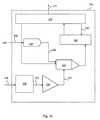
別法として、バイオセンサ・システム10は、図1bに示すように全2重通信モードで動作するように構成されてもよく、この場合オンチップ・トランスポンダ100は、インテリジェント無線周波数(RF)受信機をさらに含む。RF受信機700を備えると、バイオセンサ・システム10は、患者のアイデンティティ、ならびに、患者の年齢、体重、医療履歴などに関する情報を含む患者データベースに関係付けされてもよい識別データの読み出し以外に、複数センサ210間での選択および/またはデータ(例えば、患者の生理的パラメータ)の連続的な読み出しなどの機能を可能にする。 Alternatively, the
ここで、より詳細に図1aと図1bを参照すると、単方向通信動作と全2重通信動作を可能にするそれぞれの実施形態について、バイオセンサ・システム10のオンチップ・トランスポンダ100に接続されたセンサ・アセンブリ200のブロック図が示される。オンチップ・トランスポンダ100は、センサ210を有するセンサ・アセンブリ200を含む。センサ210は、先に述べたように、2ピン・グルコース・センサ210または3ピン・グルコース・センサ210として構成されてもよい。しかし、任意の他のセンンサが、オンチップ・トランスポンダ100と共に使用されてもよい。例えば、センサ210は、圧力トランスデューサ、血糖センサ、血液酸素センサ、心拍数モニタ、呼吸数センサなどのうちの少なくとも1つとして構成されてもよい。この点において、センサ210は、患者の任意のタイプの生理的パラメータを測定するか、監視するか、または検出する、任意のタイプのセンサとして構成されてもよい。 Referring now in more detail to FIGS. 1a and 1b, each embodiment that enables unidirectional and full duplex communication operations is connected to the on-
図2には、遠隔トランスポンダ800のブロック図が示される。遠隔トランスポンダ800は、スキャナ信号882をオンチップ・トランスポンダ100に送信することによって、生理的パラメータに関するデータを無線で要求するように構成される。遠隔トランスポンダ800はまた、オンチップ・トランスポンダ100から生理的パラメータを表すデータ信号462を受信するように構成される。同様に、遠隔トランスポンダ800とオンチップ・トランスポンダ100が、両者間で無線通信を可能にするのに十分に近接した範囲内に入ると、オンチップ・トランスポンダ100は、遠隔トランスポンダ800と通信し、スキャナ信号882を受信し、オンチップ・トランスポンダ100からデータ信号4
62を送信するように構成される。A block diagram of a remote transponder 800 is shown in FIG. Remote transponder 800 is configured to wirelessly request data regarding physiological parameters by sending
62 is configured to transmit.
単方向通信動作を可能にするバイオセンサ・システム10の実施形態について、オンチップ・トランスポンダ100の構成要素は、図1aに示すように、センサ210、電力受信機600、アナログ−デジタル(A/D)アセンブリ300、データ・プロセッサ400、およびRF送信機500を含む。全2重通信動作を可能にするバイオセンサ・システム10の実施形態の場合、RF送信機700が図1bに示すオンチップ・トランスポンダ100に含まれる。オンチップ・トランスポンダ100の構成要素のそれぞれは、従来の導電性配線によって電気的に相互接続されてもよい。しかし、電気接続は、好ましくは、従来の集積回路技術を使用して行われてもよく、その結果、オンチップ・トランスポンダ100は患者に埋め込むために十分に小さなサイズにパッケージされる。 For the embodiment of the
センサ210は、図1aと図1bに示すように、患者の生理的パラメータを表し、並列に送信される正信号と負信号からなり、センサ210からA/Dアセンブリ300へ送出されるセンサ信号234を生成するように構成される。単方向通信動作を可能にするバイオセンサ・システム10の実施形態の場合、電力受信機600は、アンテナ601においてスキャナ信号882を受信し、オンチップ・トランスポンダ100を受動給電するために電力信号602を生成するように構成される。全2重通信動作を可能にするバイオセンサ・システム10の実施形態の場合、RF受信機700は、電力受信機600へ送り出すために、アンテナ701においてスキャナ信号882を受信する。A/Dアセンブリ300は、電力信号602を受信するために、電力線604を介して電力受信機600に接続される。A/Dアセンブリ300はまた、センサ210からアナログ・センサ信号234を受信するために、センサ210に接続される。電力信号602によって給電されると、A/Dアセンブリ300は、センサ210から出てくるアナログ・センサ信号234に応答してデジタル信号372を生成するように構成される。
やはり図1aと図1bを参照すると、データ・プロセッサ400は、A/Dアセンブリ300と電力受信機600に接続されており、電力線606を介して電力信号602、ならびに、A/Dアセンブリ300からのデジタル信号372を受信するように構成される。電力信号602によって給電されることによって、データ・プロセッサ400は、デジタル信号372に応答してデータ信号462を生成するように構成される。一般に、データ・プロセッサ400は、デジタル信号372を受信し、データ信号462を生成するために、デジタル信号372をフィルタリングし、増幅し、かつ/または、符号化する。データ・プロセッサ400は、データ信号462を遠隔トランスポンダ800に送信すべき時を決定するように、データ信号462をゲート制御するように構成されてもよい。さらに、データ・プロセッサ400はまた、以下でより詳細に説明されるように、データ信号462を他のデータ(すなわち他のセンサ210からの)と加算するように構成されてもよい。 Still referring to FIGS. 1 a and 1 b, the
RF送信機500は、電力信号602を受信するために、電力線608を介して電力受信機600に接続されている。RF送信機500はまた、データ・プロセッサ400にも接続されており、データ・プロセッサ400からデータ信号462を受信するように構成される。RF送信機500はまた、遠隔トランスポンダ800にとっての返答受信のために、データ信号462を、変調し、増幅し、フィルタリングし、送信するように構成される。一般に、RF送信機500は、所望の周波数の無線搬送波上にデータ信号462を加え(すなわち変調し)、変調された信号を増幅し、遠隔トランスポンダ800に対して放射するために、変調された信号をアンテナへ送出する。 The
電力受信機600の回路要素は、当該技術分野でよく知られているように、電圧レギュレータの回路要素と同様に構成され、基準ダイオードと抵抗器とが適切な電源電圧を生成
するように配列される。しかし、電力受信機600はまた、特に、複雑さを減らすために、大きな電流を送り出すことなく、センサ210の処理回路要素に適した電圧を供給するように構成される。そのため、A/Dアセンブリ300、データ・プロセッサ400、およびRF送信機500に供給するために、電力を収集し、整流し、フィルタリングし、調節すること以外に、電力受信機600はセンサ・アセンブリ200にも実質的に安定で正確な電圧を提供する。The circuit elements of the
より具体的には、電力受信機600は、生理的パラメータが測定される精度を高めるために、実質的に偏位しないセンサ基準電圧信号642をセンサ210に供給するように構成される。センサ基準電圧信号642(すなわちセンサ210の電力)の精度と安定性は、図8aと図8bに示し、以下でより詳細に述べるように、グルコース・センサ210の特定の回路アーキテクチャによって高められる。こうして、グルコース・センサ210からの出力信号によって表されるグルコース濃度レベルの精度が改善される。先に述べたように、生理的パラメータが、センサ210によって測定されると、遠隔トランスポンダ800は、格納および/または表示のために、RF送信機500からデータ信号462を受信し、生理的パラメータを表すデータを抽出するように構成される。 More specifically, the
全2重通信動作を可能にするバイオセンサ・システム10の実施形態の場合、オンチップ・トランスポンダ100は、さらに、図1bに示すように、遠隔トランスポンダ800からスキャナ信号882を受信するように構成されたRF受信機700を含む。最も広い意味において、スキャナ信号882は、アンテナ701において受信され、RF受信機700によって復号されて、データについて要求が行われたことを、メッセージ信号702によって、オンチップ・トランスポンダ100に知らせる。電力受信機600はまた、上述したように、電力線604、606、608のそれぞれの1本の電力線によってA/Dアセンブリ300、データ・プロセッサ400、およびRF送信機500へ中継するために、スキャナ信号882を電力信号602に変換する。RF受信機700は、スキャナ信号882を、フィルタリングし、増幅し、復調し、オンチップ・トランスポンダ100の構成要素を制御するために送り出すメッセージ信号702を生成するように構成される。より具体的には、メッセージ信号702は、図1bに示すように、メッセージ/制御線704、706、708のそれぞれの1本の線によって、A/Dアセンブリ300、データ・プロセッサ400、およびRF送信機500へ送信される。RF受信機700は、メッセージ信号702がそこを通って送信されるメッセージ/制御線704、706、708のそれぞれの1本の線によって、A/Dアセンブリ300、データ・プロセッサ400、およびRF送信機500と双方向通信し得る。 For embodiments of the
複数のセンサ210を有するバイオセンサ・システム10の構成の場合、センサ210のそれぞれの1つセンサは、患者の明瞭な生理的パラメータを検知し、その生理的パラメータを表すセンサ信号234を生成するように動作し得る。例えば、患者の内部体温を測定するために、センサ210の追加の1つのセンサが設けられてもよい。さらに、患者の血液圧力レベルを測定するために、センサ210の追加の1つのセンサが設けられてもよい。複数のセンサ210は複数のセンサ信号234を生成し得る。RF受信機700は、以下でより詳細に述べるように、もとの遠隔トランスポンダ800へデータをその後送信するために、複数のセンサ210のうちの1つまたは複数のセンサからのデータについての要求を調整するように構成されてもよい。複数のセンサ210を有するバイオセンサ・システム10の実施形態の場合、データ・プロセッサ400は、センサ信号234を発生するセンサ210を識別するために、プリセット識別コードをデジタル信号372に割り当てるように構成されてもよい。こうした実施形態では、A/Dアセンブリ300は、メッセージ信号702に応答し、センサ信号234のその後の送信のために複数のセンサ信号234の間で選択するように動作するスイッチ310を含んでもよい。 In the case of a
ここで、図8aと図8bを参照すると、センサ210が、電極アセンブリ201を有するグルコース・センサ210であるバイオセンサ・システム10の構成の場合、グルコース・センサ210の特定の回路アーキテクチャは、好ましくは、センサ基準電圧信号642が正の約0.7ボルトという実質的に一定値で電極アセンブリ201に供給されるようなものである。有利には、センサ基準電圧信号642の安定性と精度は、マイクロプロセッサを使用することなく達成される。回路アーキテクチャは、共に、患者の血液と流体連通するように設置される第1端子202(すなわち作動電極)と第2端子204(すなわち基準電極)を有する電極アセンブリ201を含む。 Referring now to FIGS. 8a and 8b, in the configuration of the
2ピン・グルコース・センサ210は、患者の血液内でグルコースの酸化をもたらし、それによって、グルコン酸が形成され、GOXが還元されるように、触媒としてグルコース・オキシダーゼ(GOX)を使用して、グルコース・レベルを測定するように構成され得る。患者の血液内の酸素(O2)は、GOXと反応して、過酸化水素(H2O2)が形成
され、酸化されたGOXが再生される。O2の消費またはH2O2の形成は、プラチナで作
製されてもよい第1端子202で測定される。酸化は第1端子202で起こり、一方、還元は、銀/塩化銀で作製されてもよい第2端子204で測定される。O2が消費され、H2O2が形成される速度は、患者の血液内のグルコース濃度レベルを示す。有利には、セン
サ基準電圧信号642を正の約0.7ボルトという実質的に一定値で第1端子202に供給すると、グルコース濃度レベルを2ピン・グルコース・センサ210ならびに3ピン・グルコース・センサ210によって測定することができる精度が上がる。The 2-
やはり図8aを参照すると、2ピン・グルコース・センサ210によるグルコース濃度レベルの測定精度は、グルコース・センサ210の回路アーキテクチャによって高められる。見てわかるように、2ピン・グルコース・センサ210は、第1精密抵抗器224、第1演算増幅器220、電圧計250、第2演算増幅器230、および調節可能な第2精密抵抗器240を含む。第1精密抵抗器224は電力受信機600に接続されており、グルコース・センサ210の励起のために、電力受信機600からセンサ基準電圧信号642を受信するように構成される。第1演算増幅器220は、第1信号線212によって第1精密抵抗器224に接続されており、センサ基準電圧信号642を受信するように構成される。第1演算増幅器220は、センサ基準電圧信号642に応答して、第1演算増幅器220の非反転入力232において精密センサ基準電圧信号223を発する。 Still referring to FIG. 8 a, the accuracy of measuring the glucose concentration level by the 2-
電圧計250は、第1演算増幅器220の非反転入力と第1精密抵抗器224に接続されており、精密センサ基準電圧信号223を監視するように構成される。電圧計250は、センサ210の動作点を確立し、センサ210の応答をより正確に解釈するように構成される。電圧計250はまた、非反転第1演算増幅器220と協働して、精密センサ基準電圧信号223をバッファリングし、実質的に正確なセンサ基準電圧信号226を第1端子202に印加する。第2演算増幅器230は、第2信号線214によって第2端子204に接続されており、第1端子202に印加された正確なセンサ基準電圧信号226に応答して第2端子204から放出する電流を受信するように構成される。 The
調節可能な第2精密抵抗器240は、第2演算増幅器230の出力と反転入力との間に接続されており、第2演算増幅器230と協働して、患者の血液のグルコース・レベルに実質的に比例するセンサ信号234を生成する。図8aに示すように、接地されている非反転入力232を有する第2演算増幅器230の反転端子に電流が送り出される。第2演算増幅器230における正確な電流測定値(例えば第2端子204から放出される)は、調節可能な第2精密抵抗器240によって確立される。このようにグルコース・センサ210を構成することによって、マイクロプロセッサについての必要性および関連する較正手順および電流ドレインがなくなる。精密センサ基準電圧223ならびにセンサ210の動作点(すなわちグルコース・レベル)および第2精密抵抗器240によって決まる第2
演算増幅器230の出力は、次に、処理され、遠隔トランスポンダ800による要求によって、送信される。An adjustable
The output of
手短に図8bを参照すると、電極アセンブリ201に第3端子206(すなわち補助電極)が付加された、図8aに示す2ピン・グルコース・センサ210のブロック図と同様の3ピン・グルコース・センサ210のブロック図が示される。3ピン・グルコース・センサ210は補助制御回路260も含む。第3端子206は、第1および第2端子204,206と同じ場所に配置され、好ましくは、同様に、患者の血液と流体連通している。補助制御回路260は、第3信号線216によって、第3端子206と第2演算増幅器230との間に接続されており、第3端子206から放出される電流量を監視し、制御するように構成される。第3端子206は、第1端子202に印加される正確なセンサ基準電圧信号226の適用中に、電流を第2端子204と別の場所にそらすように構成される。3ピン・グルコース・センサ210の電極アセンブリ201に対する第3端子206の付加は、第2端子204と別の場所に電流の一部分を引き出すことによって、第2端子204に含まれる銀/塩化銀の消費を低減するのに役立ち得る。こうして、第3端子206は、電極電位を安定化するように働き、グルコース・センサ210の動作寿命は増大し得る。 Referring briefly to FIG. 8b, a 3-
ここで図5aと図5bを参照して、A/Dアセンブリ300のアーキテクチャを詳細に述べる。一般に、A/Dアセンブリ300は、含まれる生理的パラメータを、電流または電圧として表され得るアナログ電気信号に変換するように構成される。A/Dアセンブリ300はまた、センサ信号234のメッセージ暗号化、(例えばセンサ信号(複数可)234を発生する特定のセンサ210(複数可)を識別するための)固有の識別コードまたはメッセージの付加を含む、符号化を実施してもよい。さらに、A/Dアセンブリ300は、センサ信号234のインテグリティを確保するために(すなわちセンサ210から送出されたデータが、受信されたデータと同じであることを確認するために)、センサ信号234に関するエラー検出および防止ビットを含んでもよい。 The architecture of the A /
より具体的に図5aを参照すると、グルコース・センサ210からなどの単一センサ210からのセンサ信号234を受信するように構成されたバイオセンサ・システム10の実施形態についてのA/Dアセンブリ300のブロック図が示される。図5bは、複数のセンサ210から送出される複数のセンサ信号234の間での選択を可能にするスイッチ310をさらに含む、バイオセンサ・システム10の実施形態についてのA/Dアセンブリ300のブロック図である。図5aと図5bにおいて、A/Dアセンブリ300の共通下位要素は、プロセッサフィルタ320、増幅器330、電圧比較器340、A/D変換器350、コバート論理装置360、およびコントローラ370を含む。プロセッサフィルタ320は、センサ210に接続されており、センサ210からセンサ信号234を受信するように構成される。センサ信号234は、グルコース・センサ210の場合、グルコース濃度に実質的に比例するアナログ電圧が特徴である。電圧は、遠隔トランスポンダ800へ送信するのに備えて、処理されてもよいし、または、処理されていなくてもよい。いずれの場合も、さらなるセンサ信号234の調製が必要とされる場合がある。 More specifically, referring to FIG. 5 a, an A /
図5aと図5bに示すように、プロセッサフィルタ320は、センサ信号234を受信し、センサ信号234に応答して、フィルタリング済み信号322を生成する。プロセッサフィルタ320は、バイアス印加機能ならびにセンサ210の状態の測定を実施してもよい。プロセッサフィルタ320はまた、センサ信号234からスペクトル成分(例えば、高周波ノイズスパイク)を除去すると共に、オンチップ・トランスポンダ100の能力に整合するように、電圧レベルの正規化を実施してもよい。平均化、および、センサ210のデータの正確なサンプリングを確保するのに必要とされる他の機能などの、さらなる機能が、プロセッサフィルタ320によって実施されてもよい。 As shown in FIGS. 5 a and 5 b, the
増幅器330は、プロセッサフィルタ320に接続されており、プロセッサフィルタ320からフィルタリング済み信号322を受信し、信号の最小電圧と最大電圧が、A/D変換器350の限界内になるように、フィルタリング済み信号322を増幅し、デジタル化信号の最大分解能を実現するように構成されている。フィルタリング済み信号322を受信することによって、増幅器330は、フィルタリング済み信号322に応答して増幅済み信号332を生成するように構成される。電圧比較器340は、電力受信機600に接続されており、電力受信機600から電力信号602を受信し、電力信号602に応答して正規化済み電圧信号342を生成するように構成される。より具体的には、電圧比較器340は、A/Dアセンブリ300の回路要素を正規化し、回路要素の動作条件を、デジタル化されるセンサ信号234の必要性に整合させる。 The
正規化済み電圧信号342は、次に、デジタル化の前に、A/Dアセンブリ300によって、初めにサンプリングされ、次に量子化される。この機能は、増幅器330と電圧比較器340との間に接続されたA/D変換器350によって実施される。A/D変換器350は、増幅済み信号332と正規化済み電圧信号342とを受信し、これらの信号332,342に応答して変換器信号352を生成するように構成される。より正確な平均を提供するため、または、ある期間にわたって(例えば、センサ210がその中に埋め込まれる患者の数心拍動にわたって)センサ信号234の変動を追跡するために、単一サンプルが収集されてもよく、または、複数サンプルが収集されてもよい。コバート論理装置360は、A/D変換器350から変換器信号352を受信する。コバート論理装置360はまた、コバート論理装置360が、変換器信号352を受信し、変換器信号352に応答して論理信号362を生成するように、コントローラ370と双方向通信している。コバート論理装置360はまた、エラー補正および/または電圧レベルシフト回路要素を含んでもよい。
コントローラ370は、データ・プロセッサ400に関して信号伝送を同期させるために、A/Dアセンブリ300をゲート制御するように構成される。図5aに示すように、コントローラ370は、コバート論理装置360と双方向通信している。図5bを参照すると、RF受信機700を含むバイオセンサ・システム10の実施形態の場合、コントローラ370は、RF受信機700に接続されており、メッセージ/制御線704を介してRF受信機700からメッセージ信号702を受信する。RF受信機700はまた、コバート論理装置360から論理信号362を受信し、メッセージ信号702と論理信号362に応答して、デジタル信号372をその後に生成するために、A/D変換器350をデータ・プロセッサ400と同期させるように構成される。
複数のセンサ210を含むバイオセンサ・システム10の実施形態の場合、A/Dアセンブリ300は、さらに、センサ選択線314を介してコントローラ370に接続されるスイッチ310を含む。スイッチ310はまた、スイッチ信号線312を介してプロセッサフィルタ320に接続される。こうした実施形態では、コントローラ370は、メッセージ信号702に応答し、スイッチ310がプロセッサフィルタ320にセンサ信号234をその後に送信するように、スイッチ310に複数のセンサ信号234の間で選択させるよう動作する。先に述べたように、複数のセンサ210を有するバイオセンサ・システム10の構成では、データ・プロセッサ400は、センサ信号234を発生するセンサ210を識別するために、デジタル信号372にプリセット識別コードを割り当てるように構成されてもよい。デジタル信号372は、メッセージ/制御線704を介してコントローラ370に送信されるメッセージ信号702の内容に応じて、直列データのパケット(すなわち一定継続時間にわたるバースト)であってもよいし、情報が遠隔トランスポンダ800によって要求される限り続くデータストリームであってもよい。 For embodiments of the
ここで、図3を参照して、データ・プロセッサ400の特定のアーキテクチャを詳細に述べる。一般に、データ・プロセッサ400は、A/Dアセンブリ300からデジタル信号372を受信し、処理済みデータ信号462を生成するために、デジタル信号372を、フィルタリングし、増幅し、かつ/または、符号化する。データ・プロセッサ400への電力は、電力線606を介してプログラム・カウンタ430へ供給される。含まれる場合、RF受信機700は、テレメトリ動作を制御し、同期させるために、メッセージ/制御線706を介してメッセージ信号702をプログラム・カウンタ430へ送信する。データ・プロセッサ400は、データ信号462を遠隔トランスポンダ800へ送信する時を決定するために、データ信号462をゲート制御するように構成されてもよい。さらに、データ・プロセッサ400はまた、データ信号462と他のデータ(すなわち他のセンサ210からの)とを加算するように構成されてもよい。図3を見てわかるように、データ・プロセッサ400は、信号フィルタ410、増幅器420、プログラム・カウンタ430、割り込み要求装置440、計算器450、およびデジタル・フィルタ460を含む。信号フィルタ410は、A/Dアセンブリ300に接続されており、デジタル信号372を受信し、好ましくないノイズまたはアナログからデジタルへのセンサ信号234の変換の結果として含まれる場合があるエイリアシング成分を除去するように構成される。信号フィルタ410は、最終的に、フィルタリング済み信号412を生成する。フィルタリング済み信号412は、デジタル形式であり、一連のhigh電圧とlow電圧で構成される。 Referring now to FIG. 3, the specific architecture of the
やはり図3を参照すると、増幅器420は、信号フィルタ410に接続されており、信号フィルタ410からフィルタリング済み信号412を受信し、フィルタリング済み信号412に応答して増幅済み信号422を生成するように構成される。増幅器420は、データ・プロセッサ400を、アナログ−デジタル変換工程から分離させ、計算段階のための電圧レベルを調整する。先に述べたように、プログラム・カウンタ430は、RF受信機700と電力受信機600に接続されており、メッセージ信号702と電力信号602のそれぞれの1つの信号を受信するように構成される。プログラム・カウンタ430はまた、ゲート制御された信号443を生成する。割り込み要求装置440は、プログラム・カウンタ430に接続されており、ゲート制御された信号443を受信し、割り込み要求信号442を生成するように構成される。 Still referring to FIG. 3, the
計算器450は、信号フィルタ410、増幅器420、および割り込み要求装置440に接続されており、フィルタリング済み信号412、増幅済み信号422、および割り込み要求信号442のそれぞれの1つの信号を受信し、符号化信号452を生成するように構成される。この点で、プログラム・カウンタ430、割り込み要求装置440、および計算器450は、協働して、信号をゲート制御(すなわち開閉し)し、さらに、(例えば信号を発生する特定のセンサ(複数可)210を識別するために)固有のメッセージ識別コードを割り当ててもよい。さらに、同じデータパケットのメッセージの一部分またはすべてを繰り返すことによって信号の信頼性およびインテグリティを増すために、エラー検出および防止ビットが付加されてもよい。デジタル・フィルタ460は、計算器450に接続されており、計算器450から符号化信号452を受信し、データ信号462を生成するように構成される。デジタル・フィルタ460は、RF送信機500による、その後の変調のために、デジタル信号372を構成する一連のhigh電圧とlow電圧を成形する。
ここで図4を参照して、RF送信機500のアーキテクチャを詳細に述べる。一般に、RF送信機500は、所望周波数の無線搬送波上でデータ信号462を変調し、変調済み搬送波を増幅し、遠隔トランスポンダ800に対して放射するために、変調済み搬送波をRF送信機アンテナ501に送出する。図4には、データ入力フィルタ570、変調器580、第1送信機増幅器530、送信機フィルタ540、第2送信機増幅器520、表面
音響波(SAW)フィルタ510、およびRF送信機アンテナ501を備えるRF送信機500の下位要素が示される。RF送信機500は、電力線608を介して電力受信機600から、変調器580において電力信号602を受信することによって給電される。バイオセンサがRF受信機700を含む場合、メッセージ信号702もまた、メッセージ/制御線708を介して変調器580において、RF受信機700から受信される。データ入力フィルタ570は、データ・プロセッサ400に接続されており、データ・プロセッサ400からデータ信号462を受信して、高周波数スペクトル成分をフィルタリング除去し、データ信号462に応答してフィルタリング済みデータ信号585を生成するように構成される。The architecture of the
やはり図4を参照すると、変調器580は、電力受信機600、RF受信機700、およびデータ入力フィルタ570に接続されており、フィルタリング済みデータ信号585を、フィルタリング済みデータ信号585の振幅を変えることによってパルス・コード変調し、フィルタリング済みデータ信号585に応答して第1および第2変調済み信号583、586を生成するように構成される。第1送信機増幅器530は、変調器580に接続されており、変調器580から第1変調済み信号583を受信するように構成される。送信機フィルタ540は、第1送信機増幅器530によって受信されるフィードバック信号532を生成する。送信機フィルタ540は、第1送信機増幅器530と協働して、所望の無線伝送周波数の第1増幅済み信号522を作成する。第2送信機増幅器520は、変調器580と第1送信機増幅器530に接続されており、変調器580と第1送信機増幅器530から第2変調済み信号586と第1増幅済み信号522のそれぞれの1つの信号を受信し、好ましくは、遠隔トランスポンダ800に対する確実な送信に十分である所望の電力レベルを有する第2増幅済み信号512を生成するように構成される。 Still referring to FIG. 4,
図4に示すように、変調器580はまた、変調機能を助けるために、イネーブル制御582入力と変調制御584入力からの入力を受信する。変調器580は、第1および第2送信機増幅器530,520を介して、無線搬送波上にデータ信号462の処理済みデータを加える(すなわちパルス・コード変調によって変調する)。無線搬送波の振幅は、第1および第2増幅済み信号583,586によって変わる。しかし、異なるコスト、レンジ、データ・レート、エラー・レート、および周波数帯域を実現するために、他の周知の変調法が使用されてもよい。SAWフィルタ510は、第2送信機増幅器520に接続されており、第2増幅済み信号512を受信し、バイオセンサ・システム10によって利用される無線サービスのタイプについて、割り当てられた周波数スペクトル以外にある場合がある好ましくない調波を除去するように構成される。SAWフィルタ510は、第2増幅済み信号512に応答して被送信信号502を生成する。RF送信機アンテナ501は、SAWフィルタ510に接続される。被送信信号502は、RF送信機アンテナ501に送られ、RF送信機アンテナ501は、遠隔トランスポンダ800の受信アンテナ801による受信のために、被送信信号502を放射するように構成される。 As shown in FIG. 4,
ここで図6を参照して、電力受信機600の回路アーキテクチャを詳細に述べる。先に述べたように、電力受信機600は、スキャナ信号882から電力を収集するように構成される。スキャナ信号882は、電力受信アンテナ601において受信される(RF受信機700を欠く実施形態の場合)。電力は、電力線604,606,608を介して、A/Dアセンブリ300、データ・プロセッサ400、およびRF送信機500に送り出される。図6に示すように、電力受信機600の下位要素は、同調発振器610、整流器620、フィルタ630、第1レギュレータ650、第2レギュレータ660、およびセンサ基準電源640を含む。同調発振器610は、RF受信機アンテナ701または電力受信機アンテナ601に接続されてもよい。同調発振器610は、スキャナ信号882(正弦波形態)を受信し、直流(DC)電圧信号632へ変換するために、スキャナ信号882を調製するように構成される。 The circuit architecture of the
同調発振器610は、スキャナ信号882に応答して、交流(AC)電圧信号612を生成するように構成される。スキャナ信号882は、プラス電流とマイナス電流の間を循環し、ゼロ・マイクロアンペアの平均電流を有する。整流器620は、同調発振器610に接続されており、同調発振器610からAC電圧信号612を受信するように構成される。整流器620は、正の電流を加算し、ダイオード接合によって負の電流を反転させ、その結果、すべての電流が、一方向で加算される。ダイオードは閾値電圧を有し、閾値電圧は、超えられなければならず、また、電流の流れに不連続性を生じる。こうして、整流器620は、半周期ごとに不連続性を有する粗い直流電圧信号622を生成する。
フィルタ630は、整流器620に接続されており、整流器620から直流電圧信号622を受信するように構成される。フィルタ630は、実質的に平滑なDC電圧信号632を放出するために、全体が粗い直流電圧信号622の複数周期からのエネルギーを格納するように構成されたコンデンサ(図示せず)である。先に述べたように、電圧レベルは、遠隔トランスポンダ800の近接度に依存し、好ましくは、オンチップ・トランスポンダ100に給電するのに必要とされる電圧レベルより大きい。第1レギュレータ650は、フィルタ630に接続されており、フィルタ630からDC電圧信号632を受信し、A/Dアセンブリ300、データ・プロセッサ400、およびRF送信機500に給電するために、第1電圧信号652を生成するように構成される。
第2レギュレータ660は、フィルタ630に接続されており、フィルタ630からDC電圧信号632を受信し、A/Dアセンブリ300、データ・プロセッサ400、およびRF送信機500に給電するために、第2電圧信号662を生成するように構成される。第1および第2レギュレータ650,660は平滑な第1および第2電圧信号652,662を作成して、オンチップ・トランスポンダ100に対する遠隔トランスポンダ800の近接度に無関係に、オンチップ・トランスポンダ100によって要求される特定の電圧レベルの電力信号602を形成する。電力信号602は、電力線604,606,608を介してA/Dアセンブリ300、データ・プロセッサ400、およびRF送信機500に送り出される。センサ基準電源640は、フィルタ630に接続されており、フィルタ630からDC電圧信号632を受信し、センサ・アセンブリ200に電力を供給するセンサ基準電圧信号642を生成するように構成される。 The
手短に図7を参照すると、オンチップ・トランスポンダ100に含まれてもよいRF受信機700のブロック図が示される。一般に、RF受信機700は、RF受信機700によって復号されるスキャナ信号882を受信し、データについての要求が行われたことをオンチップ・トランスポンダ100に報知する。復号データは、どのデータが送出されるべきか、また、何時データを送出すべきかについて、A/Dアセンブリ300、データ・プロセッサ400、およびRF送信機500に知らせる。一般に、RF受信機700は、RF送信機500によって実施されるすべての送信機工程を逆に行う。RF受信機700の下位要素は、RF受信機アンテナ701、SAWフィルタ710、第1RF増幅器720、SAW遅延730、第2RF増幅器740、パルス発生器750、および検出器−フィルタ790を含む。RF受信機アンテナ701は、遠隔トランスポンダ800からスキャナ信号882を受信するように構成される。SAWフィルタ710は、RF受信機アンテナ701に接続されており、RF受信機アンテナ701からスキャナ信号882を受信し、RF受信機700の動作をオーバドライブするか、または、動作に干渉する場合がある、好ましくない信号からなるスキャナ信号882をフィルタリングするように構成される。 Briefly referring to FIG. 7, a block diagram of an
SAWフィルタ710は、スキャナ信号882に応答してフィルタリング済みスキャナ信号712を生成する。フィルタリング済みスキャナ信号712は、フィルタリング後に
弱い場合があり、したがって、復調回路要素が検出することができるレベルまで、第1RF増幅器720によってブーストされる(すなわち増幅される)。復調要素は、図7に示すように接続された、SAW遅延730、第2RF増幅器740、およびパルス発生器750からなる。一般に、復調要素は、協働して、スキャナ信号882に含まれるデータを再生する。第1RF増幅器720は、SAWフィルタ710に接続されており、SAWフィルタ710からフィルタリング済みスキャナ信号712を受信し、フィルタリング済みスキャナ信号712に応答して第1増幅済みRF信号722を生成するように構成される。SAW遅延730は、第1RF増幅器720に接続されており、第1RF増幅器720から第1増幅済みRF信号722を受信し、比較信号732を生成するように構成される。
第2RF増幅器740は、SAW遅延730に接続されており、SAW遅延730から比較信号732を受信するように構成される。パルス発生器750は、SAW遅延730に並列に、第1および第2RF増幅器720,740で接続され、第1および第2RF増幅器720,740と協働して、第1および第2RF増幅器720,740のそれぞれの1つの増幅器によって受信される第1および第2パルス信号752,754を生成し、それによって、第2RF増幅器740は第2増幅済みRF信号741を生成する。検出器−フィルタ790は、第2RF増幅器740に接続されており、第2RF増幅器740から第2増幅済みRF信号741を受信し、スキャナ信号882からデータを抽出し、メッセージ信号702を生成するように構成される。メッセージ信号702は、メッセージ/制御線704,706,708を介して、A/Dアセンブリ300、データ・プロセッサ400、およびRF送信機500のテレメトリ・ブロックに送られて、センサ210の読み取りが要求されたことを、ブロックに報知する。メッセージ/制御線704,706,708はまた、バイオセンサ・システム10がセンサ210のうちの複数のセンサを含む構成のために、調整およびセンサ210の選択を運び、送受信する。 The
ここで図2を参照して、遠隔トランスポンダ800の回路アーキテクチャを詳細に述べる。示すように、遠隔トランスポンダ800は、オンチップ・トランスポンダ100へデータを送信する送信用下位要素ならびにオンチップ・トランスポンダ100によって送信されたデータ信号462に含まれるデータを受信する受信用下位要素を含み得る。送信用下位要素は、発振器860、エンコーダ870、電力送信機880、および送信アンテナ883を含んでもよい。発振器860は、所定周波数のアナログ信号862を生成するように構成される。エンコーダ870は、発振器860に接続されており、アナログ信号862を受信し、変調し、アナログ信号862に応答して符号化信号872を生成するように構成される。電力送信機880は、エンコーダ870に接続されており、符号化信号872を受信し、増幅し、スキャナ信号882を生成するように構成される。送信アンテナ883は、電力送信機880に接続されており、オンチップ・トランスポンダ100に対して無線伝送するために、電力送信機880からスキャナ信号882を受信するように構成される。 Referring now to FIG. 2, the circuit architecture of the remote transponder 800 will be described in detail. As shown, remote transponder 800 may include a transmitting sub-element that transmits data to on-
やはり図2を参照すると、遠隔トランスポンダ800はまた、オンチップ・トランスポンダ100からのスキャナ信号882の受信を可能にする受信用下位要素も含み得る。遠隔トランスポンダ800の受信用下位要素は、図7に示し、上述したように、RF受信機700と構造的に、また、機能的に同じである。遠隔トランスポンダ800の受信用下位要素は、受信機アンテナ801、SAWフィルタ810、第1RF増幅器820、SAW遅延830、第2RF増幅器840、パルス発生器850、および検出器−フィルタ890を含む。受信機アンテナ801は、RF送信機500から被送信信号502を受信するように構成される。SAWフィルタ810は、受信機アンテナ801に接続されており、遠隔トランスポンダ800の動作に干渉する可能性がある好ましくない信号からなる被送信信号502を受信し、フィルタリングし、被送信信号502に応答してフィルタリング
されたRF信号812を生成するように構成される。第1RF増幅器820は、SAWフィルタ810に接続されており、SAWフィルタ810からフィルタリング済みRF信号812を受信し、フィルタリング済みRF信号812に応答して第1増幅済みRF信号822を生成するように構成される。Still referring to FIG. 2, the remote transponder 800 may also include a receiving subelement that enables reception of the
SAW遅延は、第1RF増幅器820に接続されており、第1RF増幅器820から第1増幅済みRF信号822を受信し、比較信号832を生成するように構成される。第2RF増幅器は、SAW遅延830に接続されており、SAW遅延830から比較信号832を受信するように構成される。パルス発生器は、SAW遅延830に並列に、第1および第2RF増幅器820,840で接続され、第1および第2RF増幅器820,840と協働して、第1および第2RF増幅器820,840のそれぞれの1つの増幅器によって受信される、第1および第2パルス信号852,854を生成し、それによって、第2RF増幅器840は第2増幅済みRF信号841を生成する。検出器−フィルタ890は、第2RF増幅器に接続されており、第2増幅済みRF信号841を受信し、第2増幅済みRF信号841からデジタル化データを抽出するように構成される。 The SAW delay is connected to the
図2でも示すように、バイオセンサ・システム10は、さらに、データ出力線902,904によって、検出器−フィルタ890に接続されたデコーダ900を含んでもよく、第2増幅済みRF信号841を受信し、第2増幅済みRF信号841からデジタル化データを抽出するように構成される。センサ210のそれぞれの1つのセンサが、患者の生理的パラメータを検知し、生理的パラメータに応答してセンサ信号234を生成するように動作する複数のセンサ210を有するバイオセンサ・システム10の構成の場合、デコーダ900は、データを受信すべき、複数のセンサ信号234の中から1つのセンサ信号を選択するように構成されてもよい。 As also shown in FIG. 2,
デコーダ900は、デジタル化データを元の生理的データに戻すように変換するように構成されてもよい。デコーダ900はまた、テレメトリ・メッセージの受信が成功したか否かをオペレータが知らされるように、エラーについて第2増幅済みRF信号841をチェックしてもよい。デコーダ900は、センサ信号234のデータが、手持ち式装置などの遠隔トランスポンダ800上に表示されることを可能にする。別法として、センサ信号234のデータは、コンピュータデータベースに記憶されてもよい。データベースは、テレメトリ・イベントの完全な記録を作成するために、タイム・スタンプおよび患者情報を付加してもよい。他の記録と組み合わせて、傾向および挙動がグラフ化され、解析されてもよい。 The
ここで図1と図2を参照して、バイオセンサ・システム10の動作を次に全体的に述べる。より具体的には、バイオセンサ・システム10を使用して、生理的パラメータを遠隔で監視する方法が述べられることになり、バイオセンサ・システム10は、大きくは、遠隔トランスポンダ800と、センサ210を有し、患者に埋め込み可能なオンチップ・トランスポンダ100とを備える。この方法は、遠隔トランスポンダ800によって、スキャナ信号882を遠隔で生成し、無線送信する工程を含み、スキャナ信号882は、無線信号電力とテレメトリ・データ要求とを含む。スキャナ信号882は、オンチップ・トランスポンダ100において受信され、そこでスキャナ信号882はフィルタリングされ、増幅され、復調されて、メッセージ信号702が生成される。 Referring now to FIGS. 1 and 2, the operation of the
次に、無線信号電力が、スキャナ信号882から収集され、スキャナ信号882に応答して電力信号602が生成される。同時に、センサ基準電圧信号642によって給電されることによって、センサ210は、上述した方法で、患者の少なくとも1つの生理的パラメータを検知し、アナログ・センサ信号234を生成する。電力信号602、アナログ・センサ信号234、およびメッセージ信号702は、すべて、A/Dアセンブリ300に
おいて受信され、A/Dアセンブリ300は、次に、アナログ・センサ信号を表すデジタル信号372を生成する。電力信号602、メッセージ信号702、およびデジタル信号372は、次に、データ・プロセッサ400において受信され、データ・プロセッサ400は、変調のためにデジタル信号372を調製する。データ・プロセッサ400は、次に、デジタル信号372を表すデータ信号462を生成する。電力信号602、メッセージ信号702、およびデータ信号462は、RF送信機500において受信され、RF送信機500は、次に、被送信信号502を変調し、増幅し、フィルタリングし、オンチップ・トランスポンダ100から無線送信する。遠隔トランスポンダ800は、次に、オンチップ・トランスポンダ100からの被送信信号502を受信し、患者の生理的パラメータを表すデータを抽出する。Next, wireless signal power is collected from the
センサ210が2ピン・グルコース・センサ210として構成される図8aを手短に参照すると、この方法は、さらに、正の約0.7ボルトのレベルのセンサ基準電圧信号642を生成する電力信号602を第1精密抵抗器224によって最初に調節することによって、電極アセンブリ201に供給される電力の安定性および精度を高める工程を含んでもよい。センサ基準電圧信号642は、第1精密抵抗器224で受信され、第1精密抵抗器224は、精密センサ基準電圧信号223を生成する。電圧計250は、精密センサ基準電圧信号を監視して、センサ210動作点が確立される。第1演算増幅器220は、電圧計250と協働して、精密センサ基準電圧信号223をバッファリングし、実質的に正確なセンサ基準電圧信号226が生成される。 Referring briefly to FIG. 8a where the
正確なセンサ基準電圧信号226は、第1端子202に印加されて、患者の血液との反応を引き起こし、反応によって、電流が、先に述べたように、第2端子204から放出される。電流は、第2端子204において、グルコース・レベルに比例して放出する。第2演算増幅器230に並列に接続される、第2精密抵抗器240を調節することによって、グルコース・センサ210に関して、電圧分割器が形成される。第2精密抵抗器240は、第2演算増幅器230と協働して、放出する電流のレベルを測定し、患者のグルコース・レベルに実質的に比例するセンサ信号234を生成する。 An accurate sensor
図8bを手短に参照すると、センサ210が第1および第2端子202,204と同じ場所に配置される第3端子206を含む3ピン・グルコース・センサ210である場合、グルコース・レベルを検知する方法は、さらに、電流の一部分を第2端子204と別の場所にそらす工程を含む。これは、正確なセンサ基準電圧信号226を第1端子202に印加中に、第3端子206において電流を放出することによって実施される。第3端子206から、電流は、第3電極と第2演算増幅器230の間に接続された補助制御回路260を通って流される。補助制御回路260は、第3端子206から放出する電流量を監視し、制御して、第1端子202に印加された正確なセンサ基準電圧信号226を安定させ、それによって、グルコース・センサ210の動作寿命が増加し得る。 Referring briefly to FIG. 8b, if the
本発明のさらなる変更および改良もまた、当業者に明らかになる場合がある。したがって、本明細書に述べられ、また、示されている要素の特定の組合せは、本発明のある実施形態のみを表すことを意図しており、本発明の精神および範囲内の代替装置を限定するものとしての役割を果たすことを意図しない。 Further variations and modifications of the invention may also be apparent to those skilled in the art. Accordingly, the particular combinations of elements described and illustrated herein are intended to represent only certain embodiments of the invention and limit alternative devices within the spirit and scope of the invention. Not intended to play a role as
Claims (24)
Translated fromJapaneseスキャナ信号を前記センサに送信し、前記センサからデータ信号を受信するように構成された遠隔トランスポンダと、
前記遠隔トランスポンダと無線通信しており、前記スキャナ信号を受信し、前記データ信号を送信するように構成された埋め込み可能なオンチップ・トランスポンダと、からなり、前記オンチップ・トランスポンダは、
前記患者の前記生理的パラメータを表すセンサ信号を生成するように構成されたセンサと、
前記スキャナ信号を前記遠隔トランスポンダから受信し、前記オンチップ・トランスポンダを給電する電力信号を生成するように構成された電力受信機と、
前記電力受信機と前記センサとに接続されており、前記電力信号と前記センサ信号とをそれぞれ受信し、前記電力信号と前記センサ信号とに応答してデジタル信号を生成するように構成されたアナログ−デジタル(A/D)アセンブリと、
前記A/Dアセンブリと前記電力受信機とに接続されており、前記電力信号と前記デジタル信号とをそれぞれ受信し、前記電力信号と前記デジタル信号とに応答してデータ信号を生成するように構成されたデータ・プロセッサと、
前記電力受信機と前記データ・プロセッサとに接続されており、前記電力信号と前記データ信号とをそれぞれ受信し、前記データ信号を、変調し、増幅し、フィルタリングし、送信するように構成されたRF送信機とを備え、
前記電力受信機は、前記生理的パラメータの正確な測定のために、前記センサに、実質的に偏位しないセンサ基準電圧を供給するように構成され、前記遠隔トランスポンダは、前記RF送信機から前記データ信号を受信し、前記生理的パラメータを表すデータを抽出するように構成される、バイオセンサ・システム。A biosensor system adapted to provide a substantially stable voltage to a sensor assembly implantable in said patient so that a patient's physiological parameters are accurately measured,
A remote transponder configured to send a scanner signal to the sensor and receive a data signal from the sensor;
An on-chip transponder in wireless communication with the remote transponder, configured to receive the scanner signal and to transmit the data signal, the on-chip transponder comprising:
A sensor configured to generate a sensor signal representative of the physiological parameter of the patient;
A power receiver configured to receive the scanner signal from the remote transponder and generate a power signal to power the on-chip transponder;
An analog connected to the power receiver and the sensor, configured to receive the power signal and the sensor signal, respectively, and generate a digital signal in response to the power signal and the sensor signal A digital (A / D) assembly;
Connected to the A / D assembly and the power receiver, configured to receive the power signal and the digital signal, respectively, and generate a data signal in response to the power signal and the digital signal Data processor,
Connected to the power receiver and the data processor and configured to receive the power signal and the data signal, respectively, and modulate, amplify, filter, and transmit the data signal An RF transmitter,
The power receiver is configured to provide a sensor reference voltage that is substantially unbiased to the sensor for accurate measurement of the physiological parameter, and the remote transponder is coupled to the RF transmitter from the RF transmitter. A biosensor system configured to receive a data signal and extract data representative of the physiological parameter.
前記センサ基準電圧は、正の約0.7ボルトの実質的に一定の値で、前記電極アセンブリに供給される請求項1に記載のバイオセンサ・システム。The sensor has an electrode assembly in fluid communication with the patient's blood and is configured to measure a glucose level in the patient's blood;
The biosensor system of claim 1, wherein the sensor reference voltage is provided to the electrode assembly at a substantially constant value of about 0.7 volts positive.
前記電力受信機に接続されており、前記グルコース・センサの励起のために、前記電力受信機から前記センサ基準電圧を受信するように構成された第1精密抵抗器と、
前記第1精密抵抗器に接続されており、前記第1精密抵抗器から前記センサ基準電圧を受信し、前記センサ基準電圧に応答して精密センサ基準電圧を生成するように構成された第1演算増幅器と、
前記第1演算増幅器と前記第1精密抵抗器とに接続されており、前記精密センサ基準電圧を監視し、センサ動作点を確立するように構成された電圧計と、前記第1演算増幅器および前記電圧計は、前記精密センサ基準電圧をバッファリングし、実質的に正確なセンサ基準電圧を前記第1端子に印加するように協働することと、
前記第2端子に接続されており、前記第1端子に印加される前記正確なセンサ基準電圧に応答して、前記第2端子から放出される電流を受信するように構成された第2演算増幅器と、
前記第2演算増幅器に接続されており、前記患者の血液の前記グルコース・レベルに実質的に比例するセンサ信号を生成するように、前記第2演算増幅器と協働する調節可能
な第2精密抵抗器と、
を含む請求項2に記載のバイオセンサ・システム。The glucose sensor is a 2-pin glucose sensor in which the electrode assembly has first and second terminals in fluid communication with the patient's blood, the glucose sensor further comprising:
A first precision resistor connected to the power receiver and configured to receive the sensor reference voltage from the power receiver for excitation of the glucose sensor;
A first operation connected to the first precision resistor and configured to receive the sensor reference voltage from the first precision resistor and generate a precision sensor reference voltage in response to the sensor reference voltage An amplifier;
A voltmeter connected to the first operational amplifier and the first precision resistor and configured to monitor the precision sensor reference voltage and establish a sensor operating point; the first operational amplifier; and A voltmeter cooperates to buffer the precision sensor reference voltage and apply a substantially accurate sensor reference voltage to the first terminal;
A second operational amplifier connected to the second terminal and configured to receive a current discharged from the second terminal in response to the accurate sensor reference voltage applied to the first terminal; When,
An adjustable second precision resistor coupled to the second operational amplifier and cooperating with the second operational amplifier to generate a sensor signal that is substantially proportional to the glucose level of the patient's blood. And
The biosensor system according to claim 2, comprising:
前記第3端子と前記第2演算増幅器との間に接続されており、前記第3端子から放出される電流量を監視および制御するように構成された補助制御回路を含み、
前記第3端子は、前記グルコース・センサの動作寿命が長くなるように、前記第1端子に印加される前記正確なセンサ基準電圧の印加中に、前記第2電極と別の場所に電流をそらすように構成される請求項3に記載のバイオセンサ・システム。The glucose sensor is a 3-pin glucose sensor wherein the electrode assembly further includes a third terminal disposed in the same location as the first and second terminals and in fluid communication with the patient's blood;・ The sensor further
An auxiliary control circuit connected between the third terminal and the second operational amplifier and configured to monitor and control the amount of current discharged from the third terminal;
The third terminal diverts current away from the second electrode during application of the accurate sensor reference voltage applied to the first terminal so that the operational life of the glucose sensor is extended. The biosensor system according to claim 3 configured as described above.
スキャナ信号を前記センサに送信し、前記センサからデータ信号を受信するように構成された遠隔トランスポンダと、
前記遠隔トランスポンダと無線通信しており、前記スキャナ信号を受信し、前記データ信号を送信するように構成された埋め込み可能なオンチップ・トランスポンダと、からなり、前記オンチップ・トランスポンダは、
前記患者の前記生理的パラメータを表すセンサ信号を生成するように構成されたセンサと、
前記遠隔トランスポンダから前記スキャナ信号を受信し、前記スキャナ信号を、フィルタリングし、増幅し、復調し、前記オンチップ・トランスポンダを制御するためのメッセージ信号を生成するように構成された無線周波数(RF)受信機と、
前記スキャナ信号を前記遠隔トランスポンダから受信し、前記オンチップ・トランスポンダを給電する電力信号を生成するように構成された電力受信機と、
前記電力受信機、前記RF受信機、および前記センサに接続されており、前記電力信号、前記センサ信号、および前記メッセージ信号をそれぞれ受信し、前記電力信号、前記センサ信号、および前記メッセージ信号に応答してデジタル信号を生成するように構成されたアナログ−デジタル(A/D)アセンブリと、
前記A/Dアセンブリ、前記電力受信機、および前記RF受信機に接続されており、前記電力信号、前記デジタル信号、および前記メッセージ信号をそれぞれ受信し、前記電力信号、前記デジタル信号、および前記メッセージ信号に応答してデータ信号を生成するように構成されたデータ・プロセッサと、
前記電力受信機、前記データ・プロセッサ、および前記RF受信機に接続されており、前記電力信号、前記データ信号、および前記メッセージ信号をそれぞれ受信し、前記データ信号を、変調し、増幅し、フィルタリングし、送信するように構成されたRF送信機とを備え、
前記電力受信機は、前記生理的パラメータの正確な測定のために、前記センサに、実質的に偏位しないセンサ基準電圧を供給するように構成され、前記遠隔トランスポンダは、前記RF送信機から前記データ信号を受信し、前記生理的パラメータを表すデータを抽出するように構成されるバイオセンサ・システム。A biosensor system adapted to provide a substantially stable voltage to a sensor assembly implantable in said patient so that a patient's physiological parameters are accurately measured,
A remote transponder configured to send a scanner signal to the sensor and receive a data signal from the sensor;
An on-chip transponder in wireless communication with the remote transponder, configured to receive the scanner signal and to transmit the data signal, the on-chip transponder comprising:
A sensor configured to generate a sensor signal representative of the physiological parameter of the patient;
Radio frequency (RF) configured to receive the scanner signal from the remote transponder, filter, amplify, and demodulate the scanner signal and generate a message signal to control the on-chip transponder A receiver,
A power receiver configured to receive the scanner signal from the remote transponder and generate a power signal to power the on-chip transponder;
Connected to the power receiver, the RF receiver, and the sensor, receiving the power signal, the sensor signal, and the message signal, respectively, and responding to the power signal, the sensor signal, and the message signal An analog-digital (A / D) assembly configured to generate a digital signal
Connected to the A / D assembly, the power receiver, and the RF receiver for receiving the power signal, the digital signal, and the message signal, respectively, and the power signal, the digital signal, and the message A data processor configured to generate a data signal in response to the signal;
Connected to the power receiver, the data processor, and the RF receiver for receiving the power signal, the data signal, and the message signal, respectively, modulating, amplifying, and filtering the data signal And an RF transmitter configured to transmit,
The power receiver is configured to provide a sensor reference voltage that is substantially unbiased to the sensor for accurate measurement of the physiological parameter, and the remote transponder is connected to the RF transmitter from the RF transmitter. A biosensor system configured to receive a data signal and extract data representative of the physiological parameter.
前記センサ基準電圧は、正の約0.7ボルトの実質的に一定の値で、前記電極アセンブリに供給される請求項5に記載のバイオセンサ・システム。The sensor has an electrode assembly in fluid communication with the patient's blood and is configured to measure a glucose level in the patient's blood;
The biosensor system of claim 5, wherein the sensor reference voltage is provided to the electrode assembly at a substantially constant value of about 0.7 volts positive.
および第2端子を有する2ピン・グルコース・センサであり、前記グルコース・センサはさらに、
前記電力受信機に接続されており、前記グルコース・センサの励起のために、前記電力受信機から前記センサ基準電圧を受信するように構成された第1精密抵抗器と、
前記第1精密抵抗器に接続されており、前記第1精密抵抗器から前記センサ基準電圧を受信し、前記センサ基準電圧に応答して精密センサ基準電圧を生成するように構成された第1演算増幅器と、
前記第1演算増幅器と前記第1精密抵抗器に接続されており、前記精密センサ基準電圧を監視し、センサ動作点を確立するように構成された電圧計と、前記第1演算増幅器および前記電圧計は、前記精密センサ基準電圧をバッファリングし、実質的に正確なセンサ基準電圧を前記第1端子に印加するように協働することと、
前記第2端子に接続されており、前記第1端子に印加される前記正確なセンサ基準電圧に応答して、前記第2端子から放出される電流を受信するように構成された第2演算増幅器と、
前記第2演算増幅器に接続されており、前記患者の血液の前記グルコース・レベルに実質的に比例するセンサ信号を生成するように、前記第2演算増幅器と協働する調節可能な第2精密抵抗器と、
を含む請求項6に記載のバイオセンサ・システム。The glucose sensor includes a first electrode assembly in fluid communication with the patient's blood.
And a 2-pin glucose sensor having a second terminal, the glucose sensor further comprising:
A first precision resistor connected to the power receiver and configured to receive the sensor reference voltage from the power receiver for excitation of the glucose sensor;
A first operation connected to the first precision resistor and configured to receive the sensor reference voltage from the first precision resistor and generate a precision sensor reference voltage in response to the sensor reference voltage An amplifier;
A voltmeter connected to the first operational amplifier and the first precision resistor and configured to monitor the precision sensor reference voltage and establish a sensor operating point; the first operational amplifier and the voltage; A meter buffers the precision sensor reference voltage and cooperates to apply a substantially accurate sensor reference voltage to the first terminal;
A second operational amplifier connected to the second terminal and configured to receive a current discharged from the second terminal in response to the accurate sensor reference voltage applied to the first terminal; When,
An adjustable second precision resistor coupled to the second operational amplifier and cooperating with the second operational amplifier to generate a sensor signal that is substantially proportional to the glucose level of the patient's blood. And
The biosensor system according to claim 6 comprising:
前記第3端子と前記第2演算増幅器との間に接続されており、前記第3端子から放出される電流量を監視し、制御するように構成された補助制御回路を含み、
前記第3端子は、前記グルコース・センサの動作寿命が長くなるように、前記第1端子に印加される前記正確なセンサ基準電圧の印加中に、前記第2電極と別の場所に電流をそらすように構成される請求項7に記載のバイオセンサ・システム。The glucose sensor is a 3-pin glucose sensor wherein the electrode assembly further includes a third terminal disposed in the same location as the first and second terminals and in fluid communication with the patient's blood;・ The sensor further
An auxiliary control circuit connected between the third terminal and the second operational amplifier and configured to monitor and control the amount of current discharged from the third terminal;
The third terminal diverts current away from the second electrode during application of the accurate sensor reference voltage applied to the first terminal so that the operational life of the glucose sensor is extended. The biosensor system according to claim 7 configured as described above.
前記バイオセンサに接続されており、前記バイオセンサから前記センサ信号を受信し、前記センサ信号に応答してフィルタリング済み信号を生成するように構成されたプロセッサ−フィルタと、
前記プロセッサ−フィルタに接続されており、前記プロセッサ−フィルタから前記フィルタリング済み信号を受信し、前記フィルタリング済み信号に応答して増幅済み信号を生成するように構成された増幅器と、
前記電力受信機に接続されており、前記電力受信機から前記電力信号を受信し、前記電力信号に応答して、正規化済み電圧信号を生成するように構成された電圧比較器と、
前記増幅器と前記電圧比較器とに接続されており、前記増幅器と前記電圧比較器とから
前記増幅済み信号および前記正規化済み信号のそれぞれの1つの信号を受信し、前記増幅済み信号および前記正規化済み信号のそれぞれの1つの信号に応答して、変換器信号を生成するように構成されたA/D変換器と、
前記A/D変換器に接続されており、前記A/D変換器から前記変換器信号を受信し、前記変換器信号に応答して論理信号を生成するように構成されたコバート論理装置と、
前記RF受信機と双方向通信し、前記コバート論理装置に接続されたコントローラであって、前記メッセージ信号と前記論理信号を受信し、前記メッセージ信号と前記論理信号に応答して前記デジタル信号をその後生成するために、前記A/D変換器を前記データ・プロセッサと同期させるように構成されたコントローラと、請求項5に記載のバイオセンサ・システム。The A / D assembly is:
A processor-filter connected to the biosensor and configured to receive the sensor signal from the biosensor and generate a filtered signal in response to the sensor signal;
An amplifier connected to the processor-filter and configured to receive the filtered signal from the processor-filter and generate an amplified signal in response to the filtered signal;
A voltage comparator connected to the power receiver and configured to receive the power signal from the power receiver and generate a normalized voltage signal in response to the power signal;
Connected to the amplifier and the voltage comparator, receiving one signal each of the amplified signal and the normalized signal from the amplifier and the voltage comparator, and receiving the amplified signal and the normalized signal An A / D converter configured to generate a converter signal in response to each one of the digitized signals;
A covert logic device coupled to the A / D converter, configured to receive the converter signal from the A / D converter and to generate a logic signal in response to the converter signal;
A controller that is bi-directionally communicated with the RF receiver and connected to the covert logic device; receives the message signal and the logic signal; and then transmits the digital signal in response to the message signal and the logic signal 6. The biosensor system of claim 5, wherein the controller is configured to synchronize the A / D converter with the data processor for generation.
前記A/Dアセンブリは、前記コントローラに接続されたスイッチをさらに含み、前記コントローラは、前記メッセージ信号に応答し、前記スイッチが、センサ信号の中から選択し、前記センサ信号を前記プロセッサフィルタへその後送信するようにさせるよう動作する請求項12に記載のバイオセンサ・システム。A plurality of sensors, each one of the sensors operating to sense a clear physiological parameter of the patient and generate a sensor signal representative of the clear physiological parameter;
The A / D assembly further includes a switch connected to the controller, the controller is responsive to the message signal, the switch selects among sensor signals, and the sensor signal is then sent to the processor filter. 13. The biosensor system of claim 12, wherein the biosensor system is operative to cause transmission.
前記A/Dアセンブリに接続されており、前記A/Dアセンブリからの前記デジタル化信号を受信し、好ましくないノイズを除去し、前記好ましくないノイズに応答してフィルタリング済み信号を生成するように構成された信号フィルタと、
前記信号フィルタに接続されており、前記フィルタリング済み信号を受信し、前記フィルタリング済み信号に応答して増幅済み信号を生成するように構成された増幅器と、
前記RF受信機と前記電力受信機に接続されており、前記RF受信機と前記電力受信機から前記メッセージ信号と前記電力信号のそれぞれの1つの信号を受信し、前記メッセージ信号と前記電力信号のそれぞれの1つの信号に応答してゲート制御信号を生成するように構成されたプログラム・カウンタと、
前記プログラム・カウンタに接続されており、前記プログラム・カウンタから前記ゲート制御信号を受信し、前記ゲート制御信号に応答して割り込み要求信号を生成するように構成された割り込み要求装置と、
前記信号フィルタ、前記増幅器、および前記割り込み要求装置に接続されており、前記信号フィルタ、前記増幅器、および前記割り込み要求装置から前記フィルタリング済み信号、前記増幅済み信号、および前記ゲート制御信号のそれぞれの1つの信号を受信し、前記フィルタリング済み信号、前記増幅済み信号、および前記ゲート制御信号のそれぞれの1つの信号に応答して、符号化信号を生成するように構成された計算器と、
前記計算器に接続されており、前記計算器から前記符号化信号を受信し、前記符号化信号に応答して前記データ信号を生成するように構成されたデジタル・フィルタと、
を含む請求項13に記載のバイオセンサ・システム。The data processor is
Connected to the A / D assembly and configured to receive the digitized signal from the A / D assembly, remove unwanted noise, and generate a filtered signal in response to the unwanted noise A filtered signal filter,
An amplifier connected to the signal filter, configured to receive the filtered signal and to generate an amplified signal in response to the filtered signal;
The RF receiver and the power receiver are connected, receive one signal each of the message signal and the power signal from the RF receiver and the power receiver, and the message signal and the power signal A program counter configured to generate a gate control signal in response to each one signal;
An interrupt request device connected to the program counter, configured to receive the gate control signal from the program counter and generate an interrupt request signal in response to the gate control signal;
Connected to the signal filter, the amplifier, and the interrupt request device, each of the filtered signal, the amplified signal, and the gate control signal from the signal filter, the amplifier, and the interrupt request device. A calculator configured to receive one signal and generate an encoded signal in response to each one of the filtered signal, the amplified signal, and the gating signal;
A digital filter connected to the calculator and configured to receive the encoded signal from the calculator and generate the data signal in response to the encoded signal;
The biosensor system according to claim 13, comprising:
前記データ・プロセッサに接続されており、前記データ・プロセッサから前記データ信号を受信して、高周波数スペクトル成分をフィルタリング除去し、前記データ信号に応答してフィルタリング済みデータ信号を生成するように構成されたデータ入力フィルタと、
前記電力受信機、前記RF受信機、および前記データ入力フィルタに接続されており、前記電力受信機、前記RF受信機、および前記データ入力フィルタから前記メッセージ信号、前記電力信号、および前記フィルタリング済みデータ信号のそれぞれの1つの信号を受信し、前記フィルタリング済みデータ信号の振幅を変えることによって前記フィルタリング済みデータ信号をパルス・コード変調し、前記フィルタリング済みデータ信号に応答
して第1および第2変調済み信号を生成するように構成された変調器と、
前記変調器に接続されており、前記変調器から前記1変調済み信号を受信するように構成された第1送信機増幅器と、
前記第1送信機増幅器と協働し、無線伝送の所望の周波数で第1増幅済み信号を作成する送信機フィルタと、
前記変調器と前記第1送信機増幅器に接続されており、前記変調器と前記第1送信機増幅器から前記第2変調済み信号と前記第1増幅済み信号のそれぞれの1つの信号を受信し、前記遠隔トランスポンダに対して伝送するための所望の電力レベルを有する第2増幅済み信号を生成するように構成された第2送信機増幅器と、
前記第2送信機増幅器に接続されており、前記第2増幅済み信号を受信し、前記第2増幅済み信号から好ましくない調波を除去し、前記第2増幅済み信号に応答して、被送信信号を生成するように構成された表面音響波(SAW)フィルタと,
前記SAWフィルタに接続されており、前記遠隔トランスポンダの受信アンテナによる受信のために、前記被送信信号を放射するように構成されたRF送信機アンテナと、
を含む請求項5に記載のバイオセンサ・システム。The RF transmitter is
Coupled to the data processor and configured to receive the data signal from the data processor, filter out high frequency spectral components, and generate a filtered data signal in response to the data signal Data input filter,
Connected to the power receiver, the RF receiver, and the data input filter, the message signal, the power signal, and the filtered data from the power receiver, the RF receiver, and the data input filter Receiving a respective one of the signals, pulse code modulating the filtered data signal by changing the amplitude of the filtered data signal, and first and second modulated in response to the filtered data signal A modulator configured to generate a signal;
A first transmitter amplifier connected to the modulator and configured to receive the one modulated signal from the modulator;
A transmitter filter that cooperates with the first transmitter amplifier to create a first amplified signal at a desired frequency for wireless transmission;
Connected to the modulator and the first transmitter amplifier, receiving from the modulator and the first transmitter amplifier one signal of each of the second modulated signal and the first amplified signal; A second transmitter amplifier configured to generate a second amplified signal having a desired power level for transmission to the remote transponder;
Connected to the second transmitter amplifier for receiving the second amplified signal, removing unwanted harmonics from the second amplified signal, and in response to the second amplified signal, A surface acoustic wave (SAW) filter configured to generate a signal;
An RF transmitter antenna connected to the SAW filter and configured to radiate the transmitted signal for reception by a receiving antenna of the remote transponder;
The biosensor system according to claim 5, comprising:
前記RF受信機アンテナに接続されており、前記RF受信機アンテナから前記スキャナ信号を受け取り、前記スキャナ信号に応答して交流(AC)電圧信号を生成するように構成された同調発振器と、
前記同調発振器に接続されており、前記同調発振器から前記AC電圧信号を受信し、前記AC電圧信号に応答して全体に粗い直流(DC)電圧信号を生成するように構成された整流器と、
前記整流器に接続されており、前記整流器から前記直流電圧信号を受信するように構成されたフィルタと、前記フィルタは、実質的に平滑なDC電圧信号を放出するために、前記全体に粗いDC電圧信号の複数周期からのエネルギーを格納するように構成されたコンデンサを有することと、
前記フィルタに接続されており、前記フィルタから前記DC電圧信号を受信し、第1電圧信号を生成して、前記A/Dアセンブリ、前記データ・プロセッサ、および前記RF送信機を給電するように構成された第1レギュレータと、
前記フィルタに接続されており、前記フィルタから前記DC電圧信号を受信し、前記A/Dアセンブリ、前記データ・プロセッサ、および前記RF送信機を給電する第2電圧信号を生成するように構成された第2レギュレータと、
前記フィルタに接続されており、前記フィルタから前記DC電圧信号を受信し、前記センサ・アセンブリに給電するセンサ基準電圧信号を生成するように構成されたセンサ基準電源と、
を含む請求項5に記載のバイオセンサ・システム。The power receiver
A tuned oscillator connected to the RF receiver antenna and configured to receive the scanner signal from the RF receiver antenna and generate an alternating current (AC) voltage signal in response to the scanner signal;
A rectifier connected to the tuned oscillator and configured to receive the AC voltage signal from the tuned oscillator and generate an overall coarse direct current (DC) voltage signal in response to the AC voltage signal;
A filter connected to the rectifier and configured to receive the DC voltage signal from the rectifier; and the filter generates a substantially smooth DC voltage signal to emit a substantially smooth DC voltage signal. Having a capacitor configured to store energy from multiple periods of the signal;
Connected to the filter, configured to receive the DC voltage signal from the filter, generate a first voltage signal, and power the A / D assembly, the data processor, and the RF transmitter A first regulator,
Connected to the filter and configured to receive the DC voltage signal from the filter and generate a second voltage signal that powers the A / D assembly, the data processor, and the RF transmitter A second regulator;
A sensor reference power supply coupled to the filter and configured to receive the DC voltage signal from the filter and to generate a sensor reference voltage signal for powering the sensor assembly;
The biosensor system according to claim 5, comprising:
前記遠隔トランスポンダから前記スキャナ信号を受信するように構成されたRF受信機アンテナと、
前記RF受信機アンテナに接続されており、前記RF受信機アンテナから前記スキャナ信号を受信し、好ましくない信号からなる前記スキャナ信号をフィルタリングし、前記スキャナ信号に応答してフィルタリング済みスキャナ信号を生成するように構成された表面音響波(SAW)フィルタと、
前記SAWフィルタに接続されており、前記SAWフィルタから前記フィルタリング済みスキャナ信号を受信し、前記フィルタリング済みスキャナ信号に応答して第1増幅済みスキャナ信号を生成するように構成された第1RF増幅器と、
前記第1RF増幅器に接続されており、前記第1RF増幅器から前記第1増幅済みスキャナ信号を受信し、比較信号を生成するように構成されたSAW遅延と、
前記SAW遅延に接続されており、前記SAW遅延から前記比較信号を受信するように構成された第2RF増幅器と、
前記SAW遅延に並列に、前記第1および第2RF増幅器において接続されており、前記第1および第2RF増幅器と協働して、前記第1および第2RF増幅器のそれぞれの1つの増幅器によって受信される第1および第2パルス信号を生成し、それによって、前記第2RF増幅器が第2増幅済みRF信号を生成する、パルス発生器と、
前記第2RF増幅器に接続されており、前記第2RF増幅器から前記第2増幅済みRF信号を受信し、前記メッセージ信号を生成するように構成された検出器−フィルタと、
を含む請求項5に記載のバイオセンサ・システム。The RF receiver is
An RF receiver antenna configured to receive the scanner signal from the remote transponder;
Connected to the RF receiver antenna, receives the scanner signal from the RF receiver antenna, filters the scanner signal comprising undesired signals, and generates a filtered scanner signal in response to the scanner signal A surface acoustic wave (SAW) filter configured as follows:
A first RF amplifier coupled to the SAW filter and configured to receive the filtered scanner signal from the SAW filter and generate a first amplified scanner signal in response to the filtered scanner signal;
A SAW delay connected to the first RF amplifier and configured to receive the first amplified scanner signal from the first RF amplifier and generate a comparison signal;
A second RF amplifier connected to the SAW delay and configured to receive the comparison signal from the SAW delay;
Connected in parallel with the SAW delay at the first and second RF amplifiers, and received by a respective one of the first and second RF amplifiers in cooperation with the first and second RF amplifiers. A pulse generator for generating first and second pulse signals, whereby the second RF amplifier generates a second amplified RF signal;
A detector-filter connected to the second RF amplifier and configured to receive the second amplified RF signal from the second RF amplifier and generate the message signal;
The biosensor system according to claim 5, comprising:
所定の周波数でアナログ信号を生成するように構成された発振器と、
前記発振器に接続されており、前記アナログ信号を受信し、変調し、前記アナログ信号に応答して符号化信号を生成するように構成されたエンコーダと、
前記エンコーダに接続されており、前記符号化信号を受信し、増幅し、前記スキャナ信号を生成するように構成された電力送信機と、
前記電力送信機に接続されており、前記オンチップ・トランスポンダに対する無線伝送のために前記電力送信機から前記スキャナ信号を受信するように構成された送信アンテナと、
を含む請求項5に記載のバイオセンサ・システム。The remote transponder is
An oscillator configured to generate an analog signal at a predetermined frequency;
An encoder connected to the oscillator and configured to receive and modulate the analog signal and generate an encoded signal in response to the analog signal;
A power transmitter connected to the encoder and configured to receive and amplify the encoded signal and generate the scanner signal;
A transmit antenna connected to the power transmitter and configured to receive the scanner signal from the power transmitter for wireless transmission to the on-chip transponder;
The biosensor system according to claim 5, comprising:
前記RF送信機から前記データ信号を受信するように構成された受信アンテナと、
前記受信アンテナに接続されており、前記遠隔トランスポンダと干渉する可能性がある好ましくない信号からなる前記データ信号を受信し、フィルタリングし、好ましくない信号からなる前記データ信号に応答してフィルタリング済みデータ信号を生成するように構成された表面音響波(SAW)フィルタと、
前記SAWフィルタに接続されており、前記SAWフィルタから前記フィルタリング済みデータ信号を受信し、前記フィルタリング済みデータ信号に応答して第1増幅済みデータ信号を生成するように構成された第1RF増幅器と、
前記第1RF増幅器に接続されており、前記第1RF増幅器から前記第1増幅済みデータ信号を受信し、比較信号を生成するように構成されたSAW遅延と、
前記SAW遅延に接続されており、前記SAW遅延から前記比較信号を受信するように構成された第2RF増幅器と、
前記SAW遅延に並列に、前記第1および第2RF増幅器において接続されており、前記第1および第2RF増幅器と協働して、前記第1および第2RF増幅器のそれぞれの1つの増幅器によって受信される第1および第2パルス信号を生成し、それによって、前記第2RF増幅器が第2増幅済みRF信号を生成する、パルス発生器と、
前記第2RF増幅器に接続されており、前記第2増幅済みRF信号を受信して、前記第2増幅済みRF信号からデジタル化データを抽出するように構成された検出器−フィルタと、
を含む請求項18に記載のバイオセンサ・システム。The remote transponder is
A receive antenna configured to receive the data signal from the RF transmitter;
A data signal that is connected to the receiving antenna and that receives and filters the data signal consisting of unwanted signals that may interfere with the remote transponder and that is filtered in response to the data signal consisting of unwanted signals A surface acoustic wave (SAW) filter configured to generate
A first RF amplifier connected to the SAW filter and configured to receive the filtered data signal from the SAW filter and generate a first amplified data signal in response to the filtered data signal;
A SAW delay connected to the first RF amplifier and configured to receive the first amplified data signal from the first RF amplifier and generate a comparison signal;
A second RF amplifier connected to the SAW delay and configured to receive the comparison signal from the SAW delay;
Connected in parallel with the SAW delay at the first and second RF amplifiers, and received by a respective one of the first and second RF amplifiers in cooperation with the first and second RF amplifiers. A pulse generator for generating first and second pulse signals, whereby the second RF amplifier generates a second amplified RF signal;
A detector-filter connected to the second RF amplifier and configured to receive the second amplified RF signal and extract digitized data from the second amplified RF signal;
The biosensor system according to claim 18 comprising:
前記デコーダは、前記複数のセンサのうちの、データを受信すべき1つまたは複数のセンサを選択するように構成される請求項20に記載のバイオセンサ・システム。A plurality of sensors, each one of the sensors operating to sense a clear physiological parameter of the patient and generate a sensor signal representative of the clear physiological parameter;
21. The biosensor system of claim 20, wherein the decoder is configured to select one or more sensors of the plurality of sensors that are to receive data.
a.前記遠隔トランスポンダによって、無線信号電力とテレメトリ・データ要求を含むスキャナ信号を、遠隔で生成し、無線で送信する工程と、
b.前記オンチップ・トランスポンダにおいて、前記スキャナ信号を受信し、前記スキャナ信号に応答してメッセージ信号を生成するように、前記スキャナ信号を、フィルタリングし、増幅し、復調する工程と、
c.前記スキャナ信号から前記無線信号電力を収集し、前記スキャナ信号に応答して、電力信号を生成する工程と、
d.前記センサにおいて、前記患者の少なくとも1つの生理的パラメータを検知し、前記少なくとも1つの生理的パラメータに応答してアナログ・センサ信号を生成する工程と、
e.アナログ−デジタル(A/D)アセンブリにおいて、前記電力信号、前記アナログ・センサ信号、および前記メッセージ信号を受信し、前記アナログ・センサ信号を表すデジタル信号を生成する工程と、
f.データ・プロセッサにおいて、前記電力信号、前記メッセージ信号、および前記デジタル信号を受信し、前記デジタル信号を表すデータ信号を変調し、生成するために、前記デジタル信号を調製する工程と、
g.RF送信機において、前記電力信号、前記メッセージ信号、および前記データ信号を受信し、前記データ信号を、変調し、増幅し、フィルタリングし、無線送信する工程と、
h.前記遠隔トランスポンダにおいて前記データ信号を受信し、前記患者の前記生理的パラメータを表すデータを抽出する工程と、を含む方法。A method for remotely monitoring physiological parameters using a biosensor system comprising a remote transponder and an on-chip transponder having a sensor implantable in a patient comprising:
a. Remotely generating and wirelessly transmitting a scanner signal including wireless signal power and telemetry data request by the remote transponder;
b. Filtering, amplifying, and demodulating the scanner signal to receive the scanner signal and generate a message signal in response to the scanner signal at the on-chip transponder;
c. Collecting the wireless signal power from the scanner signal and generating a power signal in response to the scanner signal;
d. Sensing at least one physiological parameter of the patient at the sensor and generating an analog sensor signal in response to the at least one physiological parameter;
e. Receiving at the analog-digital (A / D) assembly the power signal, the analog sensor signal, and the message signal and generating a digital signal representative of the analog sensor signal;
f. In a data processor, receiving the power signal, the message signal, and the digital signal, and preparing the digital signal to modulate and generate a data signal representing the digital signal;
g. In an RF transmitter, receiving the power signal, the message signal, and the data signal, modulating, amplifying, filtering, and wirelessly transmitting the data signal;
h. Receiving the data signal at the remote transponder and extracting data representative of the physiological parameter of the patient.
前記グルコース・センサを励起するために、正の約0.7ボルトのセンサ基準電圧を生成するように第1精密抵抗器によって前記電力信号を調節する工程と、
前記センサ基準電圧を第1演算増幅器において受信し、精密センサ基準電圧を生成する工程と、
センサ動作点を確立するために、前記第1演算増幅器と前記第1精密抵抗器に接続された電圧計によって、前記精密センサ基準電圧を監視する工程と、
実質的に正確なセンサ基準電圧を生成するために、前記電圧計と協働して、前記第1演算増幅器によって前記精密センサ基準電圧をバッファリングする工程と、
前記第1および第2端子における、前記患者の血液との反応に応答して、前記第2端子から電流が放出されるように、前記第1端子に前記実質的に正確なセンサ基準電圧を印加する工程と、
前記第2演算増幅器において、前記患者の血液の前記グルコース・レベルに比例する前記放出電流を受信する工程と、
前記グルコース・センサによって電圧分割器を形成するために、前記第2演算増幅器に接続された第2精密抵抗器を調節する工程と、
前記第2演算増幅器と協働して、前記第2精密抵抗器によって前記放出電流を測定する工程と、
前記グルコース・レベルに実質的に比例する前記センサ信号を生成する工程と、を含む請求項22に記載の方法。The sensor is a two-pin glucose sensor having an electrode assembly in which first and second terminals are in fluid communication with the patient's blood for sensing the patient's glucose level; step (d) further comprises ,
Adjusting the power signal with a first precision resistor to generate a positive sensor reference voltage of about 0.7 volts to excite the glucose sensor;
Receiving the sensor reference voltage at a first operational amplifier and generating a precision sensor reference voltage;
Monitoring the precision sensor reference voltage with a voltmeter connected to the first operational amplifier and the first precision resistor to establish a sensor operating point;
Buffering the precision sensor reference voltage by the first operational amplifier in cooperation with the voltmeter to generate a substantially accurate sensor reference voltage;
Applying the substantially accurate sensor reference voltage to the first terminal such that current is released from the second terminal in response to a reaction with the patient's blood at the first and second terminals. And a process of
Receiving in the second operational amplifier the emission current proportional to the glucose level of the patient's blood;
Adjusting a second precision resistor connected to the second operational amplifier to form a voltage divider with the glucose sensor;
Measuring the emission current with the second precision resistor in cooperation with the second operational amplifier;
Generating the sensor signal substantially proportional to the glucose level.
前記第1端子に対する前記実質的に正確なセンサ基準電圧の印加中に、前記第3端子において電流を放出することによって、前記第2端子と別の場所に前記電流の一部分をそらす工程と、
前記第3端子と前記第2演算増幅器との間に接続された補助制御回路において、前記放出電流を受け取る工程と、
前記第1端子に印加される前記実質的に正確なセンサ基準電圧を安定化し、前記グルコース・センサの動作寿命を増加させるために、前記第3端子から放出する電流量を監視し、制御する工程と、を含む請求項23に記載の方法。The sensor is a 3-pin glucose sensor wherein the electrode assembly further includes a third terminal disposed in the same location as the first and second terminals and in fluid communication with the patient's blood; step (d) Furthermore,
Diverting a portion of the current away from the second terminal by discharging current at the third terminal during application of the substantially accurate sensor reference voltage to the first terminal;
Receiving the emission current in an auxiliary control circuit connected between the third terminal and the second operational amplifier;
Monitoring and controlling the amount of current discharged from the third terminal to stabilize the substantially accurate sensor reference voltage applied to the first terminal and to increase the operating life of the glucose sensor. 24. The method of claim 23, comprising:
Applications Claiming Priority (2)
| Application Number | Priority Date | Filing Date | Title |
|---|---|---|---|
| US10/849,614US7125382B2 (en) | 2004-05-20 | 2004-05-20 | Embedded bio-sensor system |
| PCT/US2005/017723WO2005112744A1 (en) | 2004-05-20 | 2005-05-20 | Embedded bio-sensor system |
Publications (1)
| Publication Number | Publication Date |
|---|---|
| JP2007537841Atrue JP2007537841A (en) | 2007-12-27 |
Family
ID=35376122
Family Applications (1)
| Application Number | Title | Priority Date | Filing Date |
|---|---|---|---|
| JP2007527472APendingJP2007537841A (en) | 2004-05-20 | 2005-05-20 | Implantable biosensor system |
Country Status (8)
| Country | Link |
|---|---|
| US (4) | US7125382B2 (en) |
| EP (1) | EP1750577A4 (en) |
| JP (1) | JP2007537841A (en) |
| CN (1) | CN101022760A (en) |
| AU (1) | AU2005244973A1 (en) |
| CA (1) | CA2563953A1 (en) |
| MX (1) | MXPA06012810A (en) |
| WO (1) | WO2005112744A1 (en) |
Cited By (5)
| Publication number | Priority date | Publication date | Assignee | Title |
|---|---|---|---|---|
| JP2014516628A (en)* | 2011-04-18 | 2014-07-17 | ノビオセンス ビー.ブイ. | Biosensor |
| KR101925424B1 (en) | 2016-11-04 | 2018-12-06 | (주)제이디 | Process monitoring circuit being embeded on wafer |
| JP2019503831A (en)* | 2016-08-08 | 2019-02-14 | ウェルビーイングソフト インク. | Portable composite sensor device and measuring method for measuring a plurality of biological information |
| JP2021036228A (en)* | 2019-08-02 | 2021-03-04 | 華廣生技股▲ふん▼有限公司Bionime Corporation | Micro biosensor and measuring method thereof |
| JP2021535783A (en)* | 2018-08-31 | 2021-12-23 | エフ ホフマン−ラ ロッシュ アクチェン ゲゼルシャフト | Modular portable medical device |
Families Citing this family (359)
| Publication number | Priority date | Publication date | Assignee | Title |
|---|---|---|---|---|
| US9155496B2 (en) | 1997-03-04 | 2015-10-13 | Dexcom, Inc. | Low oxygen in vivo analyte sensor |
| US7899511B2 (en) | 2004-07-13 | 2011-03-01 | Dexcom, Inc. | Low oxygen in vivo analyte sensor |
| US8688188B2 (en) | 1998-04-30 | 2014-04-01 | Abbott Diabetes Care Inc. | Analyte monitoring device and methods of use |
| US6949816B2 (en) | 2003-04-21 | 2005-09-27 | Motorola, Inc. | Semiconductor component having first surface area for electrically coupling to a semiconductor chip and second surface area for electrically coupling to a substrate, and method of manufacturing same |
| US8346337B2 (en) | 1998-04-30 | 2013-01-01 | Abbott Diabetes Care Inc. | Analyte monitoring device and methods of use |
| US6175752B1 (en) | 1998-04-30 | 2001-01-16 | Therasense, Inc. | Analyte monitoring device and methods of use |
| US8465425B2 (en) | 1998-04-30 | 2013-06-18 | Abbott Diabetes Care Inc. | Analyte monitoring device and methods of use |
| US8974386B2 (en) | 1998-04-30 | 2015-03-10 | Abbott Diabetes Care Inc. | Analyte monitoring device and methods of use |
| US9066695B2 (en) | 1998-04-30 | 2015-06-30 | Abbott Diabetes Care Inc. | Analyte monitoring device and methods of use |
| US8480580B2 (en) | 1998-04-30 | 2013-07-09 | Abbott Diabetes Care Inc. | Analyte monitoring device and methods of use |
| US6560471B1 (en) | 2001-01-02 | 2003-05-06 | Therasense, Inc. | Analyte monitoring device and methods of use |
| EP1397068A2 (en) | 2001-04-02 | 2004-03-17 | Therasense, Inc. | Blood glucose tracking apparatus and methods |
| US20030032874A1 (en) | 2001-07-27 | 2003-02-13 | Dexcom, Inc. | Sensor head for use with implantable devices |
| US9247901B2 (en) | 2003-08-22 | 2016-02-02 | Dexcom, Inc. | Systems and methods for replacing signal artifacts in a glucose sensor data stream |
| US8010174B2 (en) | 2003-08-22 | 2011-08-30 | Dexcom, Inc. | Systems and methods for replacing signal artifacts in a glucose sensor data stream |
| US8260393B2 (en) | 2003-07-25 | 2012-09-04 | Dexcom, Inc. | Systems and methods for replacing signal data artifacts in a glucose sensor data stream |
| US6850788B2 (en) | 2002-03-25 | 2005-02-01 | Masimo Corporation | Physiological measurement communications adapter |
| US7553295B2 (en) | 2002-06-17 | 2009-06-30 | Iradimed Corporation | Liquid infusion apparatus |
| US7811231B2 (en) | 2002-12-31 | 2010-10-12 | Abbott Diabetes Care Inc. | Continuous glucose monitoring system and methods of use |
| US7587287B2 (en) | 2003-04-04 | 2009-09-08 | Abbott Diabetes Care Inc. | Method and system for transferring analyte test data |
| US7679407B2 (en) | 2003-04-28 | 2010-03-16 | Abbott Diabetes Care Inc. | Method and apparatus for providing peak detection circuitry for data communication systems |
| US8460243B2 (en) | 2003-06-10 | 2013-06-11 | Abbott Diabetes Care Inc. | Glucose measuring module and insulin pump combination |
| US8066639B2 (en) | 2003-06-10 | 2011-11-29 | Abbott Diabetes Care Inc. | Glucose measuring device for use in personal area network |
| US7722536B2 (en) | 2003-07-15 | 2010-05-25 | Abbott Diabetes Care Inc. | Glucose measuring device integrated into a holster for a personal area network device |
| WO2007120442A2 (en) | 2003-07-25 | 2007-10-25 | Dexcom, Inc. | Dual electrode system for a continuous analyte sensor |
| US7074307B2 (en) | 2003-07-25 | 2006-07-11 | Dexcom, Inc. | Electrode systems for electrochemical sensors |
| US7591801B2 (en) | 2004-02-26 | 2009-09-22 | Dexcom, Inc. | Integrated delivery device for continuous glucose sensor |
| US7519408B2 (en) | 2003-11-19 | 2009-04-14 | Dexcom, Inc. | Integrated receiver for continuous analyte sensor |
| US9135402B2 (en) | 2007-12-17 | 2015-09-15 | Dexcom, Inc. | Systems and methods for processing sensor data |
| US8160669B2 (en) | 2003-08-01 | 2012-04-17 | Dexcom, Inc. | Transcutaneous analyte sensor |
| US8060173B2 (en) | 2003-08-01 | 2011-11-15 | Dexcom, Inc. | System and methods for processing analyte sensor data |
| US20080119703A1 (en) | 2006-10-04 | 2008-05-22 | Mark Brister | Analyte sensor |
| US7774145B2 (en) | 2003-08-01 | 2010-08-10 | Dexcom, Inc. | Transcutaneous analyte sensor |
| US20100168657A1 (en) | 2003-08-01 | 2010-07-01 | Dexcom, Inc. | System and methods for processing analyte sensor data |
| US20190357827A1 (en) | 2003-08-01 | 2019-11-28 | Dexcom, Inc. | Analyte sensor |
| US7920906B2 (en) | 2005-03-10 | 2011-04-05 | Dexcom, Inc. | System and methods for processing analyte sensor data for sensor calibration |
| US20140121989A1 (en) | 2003-08-22 | 2014-05-01 | Dexcom, Inc. | Systems and methods for processing analyte sensor data |
| US9247900B2 (en) | 2004-07-13 | 2016-02-02 | Dexcom, Inc. | Analyte sensor |
| US8423114B2 (en) | 2006-10-04 | 2013-04-16 | Dexcom, Inc. | Dual electrode system for a continuous analyte sensor |
| ATE480761T1 (en) | 2003-12-05 | 2010-09-15 | Dexcom Inc | CALIBRATION METHODS FOR A CONTINUOUSLY WORKING ANALYTICAL SENSOR |
| US8364231B2 (en) | 2006-10-04 | 2013-01-29 | Dexcom, Inc. | Analyte sensor |
| US8287453B2 (en) | 2003-12-05 | 2012-10-16 | Dexcom, Inc. | Analyte sensor |
| US11633133B2 (en) | 2003-12-05 | 2023-04-25 | Dexcom, Inc. | Dual electrode system for a continuous analyte sensor |
| WO2005089103A2 (en) | 2004-02-17 | 2005-09-29 | Therasense, Inc. | Method and system for providing data communication in continuous glucose monitoring and management system |
| WO2009048462A1 (en) | 2007-10-09 | 2009-04-16 | Dexcom, Inc. | Integrated insulin delivery system with continuous glucose sensor |
| US8808228B2 (en) | 2004-02-26 | 2014-08-19 | Dexcom, Inc. | Integrated medicament delivery device for use with continuous analyte sensor |
| US8092549B2 (en) | 2004-09-24 | 2012-01-10 | The Invention Science Fund I, Llc | Ciliated stent-like-system |
| US8024036B2 (en) | 2007-03-19 | 2011-09-20 | The Invention Science Fund I, Llc | Lumen-traveling biological interface device and method of use |
| US9011329B2 (en) | 2004-04-19 | 2015-04-21 | Searete Llc | Lumenally-active device |
| US8512219B2 (en) | 2004-04-19 | 2013-08-20 | The Invention Science Fund I, Llc | Bioelectromagnetic interface system |
| US7850676B2 (en) | 2004-04-19 | 2010-12-14 | The Invention Science Fund I, Llc | System with a reservoir for perfusion management |
| US8353896B2 (en) | 2004-04-19 | 2013-01-15 | The Invention Science Fund I, Llc | Controllable release nasal system |
| US8000784B2 (en) | 2004-04-19 | 2011-08-16 | The Invention Science Fund I, Llc | Lumen-traveling device |
| US8361013B2 (en) | 2004-04-19 | 2013-01-29 | The Invention Science Fund I, Llc | Telescoping perfusion management system |
| US8337482B2 (en) | 2004-04-19 | 2012-12-25 | The Invention Science Fund I, Llc | System for perfusion management |
| US7998060B2 (en) | 2004-04-19 | 2011-08-16 | The Invention Science Fund I, Llc | Lumen-traveling delivery device |
| US8792955B2 (en) | 2004-05-03 | 2014-07-29 | Dexcom, Inc. | Transcutaneous analyte sensor |
| US7125382B2 (en)* | 2004-05-20 | 2006-10-24 | Digital Angel Corporation | Embedded bio-sensor system |
| EP1810185A4 (en) | 2004-06-04 | 2010-01-06 | Therasense Inc | Diabetes care host-client architecture and data management system |
| US8886272B2 (en) | 2004-07-13 | 2014-11-11 | Dexcom, Inc. | Analyte sensor |
| US8452368B2 (en) | 2004-07-13 | 2013-05-28 | Dexcom, Inc. | Transcutaneous analyte sensor |
| US20070045902A1 (en) | 2004-07-13 | 2007-03-01 | Brauker James H | Analyte sensor |
| US7654956B2 (en) | 2004-07-13 | 2010-02-02 | Dexcom, Inc. | Transcutaneous analyte sensor |
| US20060016700A1 (en) | 2004-07-13 | 2006-01-26 | Dexcom, Inc. | Transcutaneous analyte sensor |
| US7783333B2 (en) | 2004-07-13 | 2010-08-24 | Dexcom, Inc. | Transcutaneous medical device with variable stiffness |
| US8565848B2 (en) | 2004-07-13 | 2013-10-22 | Dexcom, Inc. | Transcutaneous analyte sensor |
| US8336553B2 (en)* | 2004-09-21 | 2012-12-25 | Medtronic Xomed, Inc. | Auto-titration of positive airway pressure machine with feedback from implantable sensor |
| CA2587912A1 (en)* | 2004-11-19 | 2006-05-26 | Sensormatic Electronics Corporation | Technique and hardware for communicating with backscatter radio frequency identification readers |
| US9636450B2 (en) | 2007-02-19 | 2017-05-02 | Udo Hoss | Pump system modular components for delivering medication and analyte sensing at seperate insertion sites |
| US8029441B2 (en) | 2006-02-28 | 2011-10-04 | Abbott Diabetes Care Inc. | Analyte sensor transmitter unit configuration for a data monitoring and management system |
| US9788771B2 (en) | 2006-10-23 | 2017-10-17 | Abbott Diabetes Care Inc. | Variable speed sensor insertion devices and methods of use |
| US7545272B2 (en) | 2005-02-08 | 2009-06-09 | Therasense, Inc. | RF tag on test strips, test strip vials and boxes |
| WO2006091499A2 (en)* | 2005-02-24 | 2006-08-31 | Firefly Power Technologies, Inc. | Method, apparatus and system for power transmitssion |
| US20070149162A1 (en)* | 2005-02-24 | 2007-06-28 | Powercast, Llc | Pulse transmission method |
| US20090076360A1 (en) | 2007-09-13 | 2009-03-19 | Dexcom, Inc. | Transcutaneous analyte sensor |
| US8133178B2 (en) | 2006-02-22 | 2012-03-13 | Dexcom, Inc. | Analyte sensor |
| EP3827747A1 (en) | 2005-04-28 | 2021-06-02 | Otsuka Pharmaceutical Co., Ltd. | Pharma-informatics system |
| US8802183B2 (en) | 2005-04-28 | 2014-08-12 | Proteus Digital Health, Inc. | Communication system with enhanced partial power source and method of manufacturing same |
| US8836513B2 (en) | 2006-04-28 | 2014-09-16 | Proteus Digital Health, Inc. | Communication system incorporated in an ingestible product |
| US9198608B2 (en) | 2005-04-28 | 2015-12-01 | Proteus Digital Health, Inc. | Communication system incorporated in a container |
| US8912908B2 (en) | 2005-04-28 | 2014-12-16 | Proteus Digital Health, Inc. | Communication system with remote activation |
| US8730031B2 (en) | 2005-04-28 | 2014-05-20 | Proteus Digital Health, Inc. | Communication system using an implantable device |
| US8112240B2 (en) | 2005-04-29 | 2012-02-07 | Abbott Diabetes Care Inc. | Method and apparatus for providing leak detection in data monitoring and management systems |
| US7768408B2 (en) | 2005-05-17 | 2010-08-03 | Abbott Diabetes Care Inc. | Method and system for providing data management in data monitoring system |
| US20060276702A1 (en)* | 2005-06-03 | 2006-12-07 | Mcginnis William | Neurophysiological wireless bio-sensor |
| AU2006282828B2 (en) | 2005-08-23 | 2013-01-31 | Smith & Nephew, Inc | Telemetric orthopaedic implant |
| JP2009507224A (en) | 2005-08-31 | 2009-02-19 | ユニヴァーシティー オブ ヴァージニア パテント ファンデーション | Improving the accuracy of continuous glucose sensors |
| US8547248B2 (en) | 2005-09-01 | 2013-10-01 | Proteus Digital Health, Inc. | Implantable zero-wire communications system |
| US8880138B2 (en) | 2005-09-30 | 2014-11-04 | Abbott Diabetes Care Inc. | Device for channeling fluid and methods of use |
| US8211088B2 (en)* | 2005-10-14 | 2012-07-03 | Boston Scientific Scimed, Inc. | Catheter with controlled lumen recovery |
| US7583190B2 (en) | 2005-10-31 | 2009-09-01 | Abbott Diabetes Care Inc. | Method and apparatus for providing data communication in data monitoring and management systems |
| US7766829B2 (en) | 2005-11-04 | 2010-08-03 | Abbott Diabetes Care Inc. | Method and system for providing basal profile modification in analyte monitoring and management systems |
| KR100653199B1 (en)* | 2005-11-18 | 2006-12-05 | 삼성전자주식회사 | RF receiving device and method for removing a component from a received signal using a local signal |
| US7774038B2 (en) | 2005-12-30 | 2010-08-10 | Medtronic Minimed, Inc. | Real-time self-calibrating sensor system and method |
| US9757061B2 (en) | 2006-01-17 | 2017-09-12 | Dexcom, Inc. | Low oxygen in vivo analyte sensor |
| ES2871822T3 (en)* | 2006-02-22 | 2021-11-02 | Dexcom Inc | Analyte sensor |
| US7826879B2 (en) | 2006-02-28 | 2010-11-02 | Abbott Diabetes Care Inc. | Analyte sensors and methods of use |
| US7885698B2 (en) | 2006-02-28 | 2011-02-08 | Abbott Diabetes Care Inc. | Method and system for providing continuous calibration of implantable analyte sensors |
| US8226891B2 (en) | 2006-03-31 | 2012-07-24 | Abbott Diabetes Care Inc. | Analyte monitoring devices and methods therefor |
| US9392969B2 (en) | 2008-08-31 | 2016-07-19 | Abbott Diabetes Care Inc. | Closed loop control and signal attenuation detection |
| US8346335B2 (en) | 2008-03-28 | 2013-01-01 | Abbott Diabetes Care Inc. | Analyte sensor calibration management |
| US7801582B2 (en) | 2006-03-31 | 2010-09-21 | Abbott Diabetes Care Inc. | Analyte monitoring and management system and methods therefor |
| US9675290B2 (en) | 2012-10-30 | 2017-06-13 | Abbott Diabetes Care Inc. | Sensitivity calibration of in vivo sensors used to measure analyte concentration |
| US9326709B2 (en) | 2010-03-10 | 2016-05-03 | Abbott Diabetes Care Inc. | Systems, devices and methods for managing glucose levels |
| US8219173B2 (en) | 2008-09-30 | 2012-07-10 | Abbott Diabetes Care Inc. | Optimizing analyte sensor calibration |
| US7620438B2 (en) | 2006-03-31 | 2009-11-17 | Abbott Diabetes Care Inc. | Method and system for powering an electronic device |
| US9220917B2 (en) | 2006-04-12 | 2015-12-29 | The Invention Science Fund I, Llc | Systems for autofluorescent imaging and target ablation |
| US20120035540A1 (en) | 2006-04-12 | 2012-02-09 | Searete Llc, A Limited Liability Corporation Of The State Of Delaware | Event-based control of a lumen traveling device |
| JP2009544338A (en) | 2006-05-02 | 2009-12-17 | プロテウス バイオメディカル インコーポレイテッド | Treatment regimen customized to the patient |
| DE102006020866A1 (en)* | 2006-05-04 | 2007-11-15 | Siemens Ag | Analyte e.g. DNA, analyzer for use in biosensor, has transponder e.g. passive transponder, provided for wireless information exchange with selection device, which is electrically connected with oscillating crystal |
| US20070279217A1 (en)* | 2006-06-01 | 2007-12-06 | H-Micro, Inc. | Integrated mobile healthcare system for cardiac care |
| WO2007143225A2 (en) | 2006-06-07 | 2007-12-13 | Abbott Diabetes Care, Inc. | Analyte monitoring system and method |
| US8917178B2 (en)* | 2006-06-09 | 2014-12-23 | Dominic M. Kotab | RFID system and method for storing information related to a vehicle or an owner of the vehicle |
| US9119582B2 (en) | 2006-06-30 | 2015-09-01 | Abbott Diabetes Care, Inc. | Integrated analyte sensor and infusion device and methods therefor |
| US7832647B2 (en)* | 2006-06-30 | 2010-11-16 | Semiconductor Energy Laboratory Co., Ltd. | Semiconductor device |
| US7724145B2 (en)* | 2006-07-20 | 2010-05-25 | Intelleflex Corporation | Self-charging RFID tag with long life |
| US7831287B2 (en) | 2006-10-04 | 2010-11-09 | Dexcom, Inc. | Dual electrode system for a continuous analyte sensor |
| EP2087589B1 (en) | 2006-10-17 | 2011-11-23 | Proteus Biomedical, Inc. | Low voltage oscillator for medical devices |
| US20080092638A1 (en)* | 2006-10-19 | 2008-04-24 | Bayer Healthcare Llc | Wireless analyte monitoring system |
| SG175681A1 (en) | 2006-10-25 | 2011-11-28 | Proteus Biomedical Inc | Controlled activation ingestible identifier |
| US10914698B2 (en) | 2006-11-16 | 2021-02-09 | General Electric Company | Sensing method and system |
| US9538657B2 (en) | 2012-06-29 | 2017-01-03 | General Electric Company | Resonant sensor and an associated sensing method |
| US9589686B2 (en) | 2006-11-16 | 2017-03-07 | General Electric Company | Apparatus for detecting contaminants in a liquid and a system for use thereof |
| US9536122B2 (en) | 2014-11-04 | 2017-01-03 | General Electric Company | Disposable multivariable sensing devices having radio frequency based sensors |
| US9658178B2 (en) | 2012-09-28 | 2017-05-23 | General Electric Company | Sensor systems for measuring an interface level in a multi-phase fluid composition |
| US8718193B2 (en)* | 2006-11-20 | 2014-05-06 | Proteus Digital Health, Inc. | Active signal processing personal health signal receivers |
| DE102006056723B3 (en) | 2006-12-01 | 2007-07-19 | Dräger Medical AG & Co. KG | Medical system for use in intensive care unit of hospital, has medical work station detecting physiological data of patient, and system allocating physiological data and patient data to one another based on marking signal |
| US9118990B2 (en)* | 2007-01-06 | 2015-08-25 | Apple Inc. | Connectors designed for ease of use |
| US8650925B2 (en) | 2007-01-05 | 2014-02-18 | Apple Inc. | Extrusion method for fabricating a compact tube with internal features |
| US8311255B2 (en)* | 2007-01-05 | 2012-11-13 | Apple Inc. | Headset with microphone and connector co-location |
| EP2640170B1 (en) | 2007-01-06 | 2015-07-29 | Apple Inc. | Wireless headset comprising a housing and an earbud electrically coupled to the housing by a flexible circuit board |
| EP3471383B1 (en) | 2007-01-06 | 2021-04-07 | Apple Inc. | An earbud |
| CN101686800A (en) | 2007-02-01 | 2010-03-31 | 普罗秋斯生物医学公司 | Ingestible Event Marker System |
| US8956288B2 (en) | 2007-02-14 | 2015-02-17 | Proteus Digital Health, Inc. | In-body power source having high surface area electrode |
| US20080199894A1 (en) | 2007-02-15 | 2008-08-21 | Abbott Diabetes Care, Inc. | Device and method for automatic data acquisition and/or detection |
| US8123686B2 (en)* | 2007-03-01 | 2012-02-28 | Abbott Diabetes Care Inc. | Method and apparatus for providing rolling data in communication systems |
| EP2124725A1 (en)* | 2007-03-09 | 2009-12-02 | Proteus Biomedical, Inc. | In-body device having a multi-directional transmitter |
| EP2063771A1 (en) | 2007-03-09 | 2009-06-03 | Proteus Biomedical, Inc. | In-body device having a deployable antenna |
| US20080242950A1 (en)* | 2007-03-30 | 2008-10-02 | Searete Llc, A Limited Liability Corporation Of The State Of Delaware | Computational user-health testing |
| US8065240B2 (en) | 2007-10-31 | 2011-11-22 | The Invention Science Fund I | Computational user-health testing responsive to a user interaction with advertiser-configured content |
| US20090112621A1 (en)* | 2007-10-30 | 2009-04-30 | Searete Llc, A Limited Liability Corporation Of The State Of Delaware | Computational user-health testing responsive to a user interaction with advertiser-configured content |
| US20090112616A1 (en)* | 2007-10-30 | 2009-04-30 | Searete Llc, A Limited Liability Corporation Of The State Of Delaware | Polling for interest in computational user-health test output |
| CA2683953C (en) | 2007-04-14 | 2016-08-02 | Abbott Diabetes Care Inc. | Method and apparatus for providing data processing and control in medical communication system |
| EP2137637A4 (en) | 2007-04-14 | 2012-06-20 | Abbott Diabetes Care Inc | Method and apparatus for providing data processing and control in medical communication system |
| WO2008130897A2 (en) | 2007-04-14 | 2008-10-30 | Abbott Diabetes Care, Inc. | Method and apparatus for providing data processing and control in medical communication system |
| US10111608B2 (en) | 2007-04-14 | 2018-10-30 | Abbott Diabetes Care Inc. | Method and apparatus for providing data processing and control in medical communication system |
| WO2008130898A1 (en) | 2007-04-14 | 2008-10-30 | Abbott Diabetes Care, Inc. | Method and apparatus for providing data processing and control in medical communication system |
| US8665091B2 (en) | 2007-05-08 | 2014-03-04 | Abbott Diabetes Care Inc. | Method and device for determining elapsed sensor life |
| US8456301B2 (en) | 2007-05-08 | 2013-06-04 | Abbott Diabetes Care Inc. | Analyte monitoring system and methods |
| US7928850B2 (en) | 2007-05-08 | 2011-04-19 | Abbott Diabetes Care Inc. | Analyte monitoring system and methods |
| US8461985B2 (en) | 2007-05-08 | 2013-06-11 | Abbott Diabetes Care Inc. | Analyte monitoring system and methods |
| US8560038B2 (en) | 2007-05-14 | 2013-10-15 | Abbott Diabetes Care Inc. | Method and apparatus for providing data processing and control in a medical communication system |
| US8103471B2 (en) | 2007-05-14 | 2012-01-24 | Abbott Diabetes Care Inc. | Method and apparatus for providing data processing and control in a medical communication system |
| US10002233B2 (en) | 2007-05-14 | 2018-06-19 | Abbott Diabetes Care Inc. | Method and apparatus for providing data processing and control in a medical communication system |
| US8239166B2 (en) | 2007-05-14 | 2012-08-07 | Abbott Diabetes Care Inc. | Method and apparatus for providing data processing and control in a medical communication system |
| US8260558B2 (en) | 2007-05-14 | 2012-09-04 | Abbott Diabetes Care Inc. | Method and apparatus for providing data processing and control in a medical communication system |
| US8600681B2 (en) | 2007-05-14 | 2013-12-03 | Abbott Diabetes Care Inc. | Method and apparatus for providing data processing and control in a medical communication system |
| US9125548B2 (en) | 2007-05-14 | 2015-09-08 | Abbott Diabetes Care Inc. | Method and apparatus for providing data processing and control in a medical communication system |
| US8444560B2 (en) | 2007-05-14 | 2013-05-21 | Abbott Diabetes Care Inc. | Method and apparatus for providing data processing and control in a medical communication system |
| US8115618B2 (en) | 2007-05-24 | 2012-02-14 | Proteus Biomedical, Inc. | RFID antenna for in-body device |
| US8649840B2 (en)* | 2007-06-07 | 2014-02-11 | Microchips, Inc. | Electrochemical biosensors and arrays |
| WO2008154312A1 (en) | 2007-06-08 | 2008-12-18 | Dexcom, Inc. | Integrated medicament delivery device for use with continuous analyte sensor |
| WO2008157820A1 (en) | 2007-06-21 | 2008-12-24 | Abbott Diabetes Care, Inc. | Health management devices and methods |
| AU2008265542B2 (en) | 2007-06-21 | 2014-07-24 | Abbott Diabetes Care Inc. | Health monitor |
| US8160900B2 (en) | 2007-06-29 | 2012-04-17 | Abbott Diabetes Care Inc. | Analyte monitoring and management device and method to analyze the frequency of user interaction with the device |
| US8330579B2 (en) | 2007-07-05 | 2012-12-11 | Baxter International Inc. | Radio-frequency auto-identification system for dialysis systems |
| US8105282B2 (en) | 2007-07-13 | 2012-01-31 | Iradimed Corporation | System and method for communication with an infusion device |
| JP5147321B2 (en)* | 2007-07-19 | 2013-02-20 | パナソニック株式会社 | Semiconductor integrated circuit and sensor drive / measurement system |
| US8834366B2 (en) | 2007-07-31 | 2014-09-16 | Abbott Diabetes Care Inc. | Method and apparatus for providing analyte sensor calibration |
| US9046919B2 (en) | 2007-08-20 | 2015-06-02 | Hmicro, Inc. | Wearable user interface device, system, and method of use |
| US8926509B2 (en)* | 2007-08-24 | 2015-01-06 | Hmicro, Inc. | Wireless physiological sensor patches and systems |
| US8570187B2 (en) | 2007-09-06 | 2013-10-29 | Smith & Nephew, Inc. | System and method for communicating with a telemetric implant |
| JP5248613B2 (en)* | 2007-09-17 | 2013-07-31 | レッド・アイボリー・エルエルシー | Self-actuating signal generation detection apparatus and method |
| WO2009040802A1 (en)* | 2007-09-24 | 2009-04-02 | Nexense Ltd. | Method and apparatus for monitoring predetermined parameters in a body |
| DK2192946T3 (en) | 2007-09-25 | 2022-11-21 | Otsuka Pharma Co Ltd | In-body device with virtual dipole signal amplification |
| US20110019824A1 (en) | 2007-10-24 | 2011-01-27 | Hmicro, Inc. | Low power radiofrequency (rf) communication systems for secure wireless patch initialization and methods of use |
| US8611319B2 (en)* | 2007-10-24 | 2013-12-17 | Hmicro, Inc. | Methods and apparatus to retrofit wired healthcare and fitness systems for wireless operation |
| US8417312B2 (en) | 2007-10-25 | 2013-04-09 | Dexcom, Inc. | Systems and methods for processing sensor data |
| EP2217914A1 (en)* | 2007-11-02 | 2010-08-18 | Edwards Lifesciences Corporation | Analyte monitoring system having back-up power source for use in either transport of the system or primary power loss |
| KR101586193B1 (en)* | 2007-11-27 | 2016-01-18 | 프로테우스 디지털 헬스, 인코포레이티드 | Transbody communication systems employing communication channels |
| US20090188811A1 (en) | 2007-11-28 | 2009-07-30 | Edwards Lifesciences Corporation | Preparation and maintenance of sensors |
| US8290559B2 (en) | 2007-12-17 | 2012-10-16 | Dexcom, Inc. | Systems and methods for processing sensor data |
| US20090164239A1 (en) | 2007-12-19 | 2009-06-25 | Abbott Diabetes Care, Inc. | Dynamic Display Of Glucose Information |
| EP2252196A4 (en) | 2008-02-21 | 2013-05-15 | Dexcom Inc | Systems and methods for processing, transmitting and displaying sensor data |
| CN104376659B (en) | 2008-03-05 | 2019-10-25 | 普罗透斯数字保健公司 | The ingestible event flag of multi-modal communications and system, and the method using it |
| US8396528B2 (en) | 2008-03-25 | 2013-03-12 | Dexcom, Inc. | Analyte sensor |
| EP2982383B1 (en) | 2008-04-10 | 2019-05-15 | Abbott Diabetes Care, Inc. | Method for sterilizing an analyte sensor |
| AT505632B1 (en)* | 2008-05-14 | 2009-03-15 | Arc Austrian Res Centers Gmbh | METHOD FOR DATA TRANSMISSION |
| US8429225B2 (en) | 2008-05-21 | 2013-04-23 | The Invention Science Fund I, Llc | Acquisition and presentation of data indicative of an extent of congruence between inferred mental states of authoring users |
| US9161715B2 (en)* | 2008-05-23 | 2015-10-20 | Invention Science Fund I, Llc | Determination of extent of congruity between observation of authoring user and observation of receiving user |
| US9192300B2 (en)* | 2008-05-23 | 2015-11-24 | Invention Science Fund I, Llc | Acquisition and particular association of data indicative of an inferred mental state of an authoring user |
| US8615664B2 (en)* | 2008-05-23 | 2013-12-24 | The Invention Science Fund I, Llc | Acquisition and particular association of inference data indicative of an inferred mental state of an authoring user and source identity data |
| US20090292658A1 (en)* | 2008-05-23 | 2009-11-26 | Searete Llc, A Limited Liability Corporation Of The State Of Delaware | Acquisition and particular association of inference data indicative of inferred mental states of authoring users |
| US9101263B2 (en)* | 2008-05-23 | 2015-08-11 | The Invention Science Fund I, Llc | Acquisition and association of data indicative of an inferred mental state of an authoring user |
| US7826382B2 (en) | 2008-05-30 | 2010-11-02 | Abbott Diabetes Care Inc. | Close proximity communication device and methods |
| AU2009268827B2 (en) | 2008-07-08 | 2013-10-24 | Proteus Digital Health, Inc. | Ingestible event marker data framework |
| US8876755B2 (en) | 2008-07-14 | 2014-11-04 | Abbott Diabetes Care Inc. | Closed loop control system interface and methods |
| WO2010012035A1 (en)* | 2008-07-31 | 2010-02-04 | Newcastle Innovation Limited | A harmonics-based wireless transmission device and associated method |
| MY154217A (en) | 2008-08-13 | 2015-05-15 | Proteus Digital Health Inc | Ingestible circuitry |
| EP4227675B1 (en) | 2008-09-19 | 2024-12-11 | DexCom, Inc. | Particle-containing membrane and particulate electrode for analyte sensors |
| WO2010045385A2 (en)* | 2008-10-14 | 2010-04-22 | Proteus Biomedical, Inc. | Method and system for incorporating physiologic data in a gaming environment |
| US8036748B2 (en) | 2008-11-13 | 2011-10-11 | Proteus Biomedical, Inc. | Ingestible therapy activator system and method |
| JP2012509103A (en)* | 2008-11-18 | 2012-04-19 | プロテウス バイオメディカル インコーポレイテッド | Sensing system, device, and method for therapy coordination |
| US20100140958A1 (en)* | 2008-12-04 | 2010-06-10 | Searete Llc, A Limited Liability Corporation Of The State Of Delaware | Method for powering devices from intraluminal pressure changes |
| US9631610B2 (en)* | 2008-12-04 | 2017-04-25 | Deep Science, Llc | System for powering devices from intraluminal pressure changes |
| US9567983B2 (en)* | 2008-12-04 | 2017-02-14 | Deep Science, Llc | Method for generation of power from intraluminal pressure changes |
| US9526418B2 (en)* | 2008-12-04 | 2016-12-27 | Deep Science, Llc | Device for storage of intraluminally generated power |
| US9353733B2 (en)* | 2008-12-04 | 2016-05-31 | Deep Science, Llc | Device and system for generation of power from intraluminal pressure changes |
| US9759202B2 (en)* | 2008-12-04 | 2017-09-12 | Deep Science, Llc | Method for generation of power from intraluminal pressure changes |
| EP2358270A4 (en) | 2008-12-11 | 2014-08-13 | Proteus Digital Health Inc | Evaluation of gastrointestinal function using portable electroviscerography systems and methods of using the same |
| US9659423B2 (en) | 2008-12-15 | 2017-05-23 | Proteus Digital Health, Inc. | Personal authentication apparatus system and method |
| US9439566B2 (en) | 2008-12-15 | 2016-09-13 | Proteus Digital Health, Inc. | Re-wearable wireless device |
| TWI503101B (en) | 2008-12-15 | 2015-10-11 | Proteus Digital Health Inc | Body-associated receiver and method |
| US20100160756A1 (en)* | 2008-12-24 | 2010-06-24 | Edwards Lifesciences Corporation | Membrane Layer for Electrochemical Biosensor and Method of Accommodating Electromagnetic and Radiofrequency Fields |
| KR20110103446A (en) | 2009-01-06 | 2011-09-20 | 프로테우스 바이오메디컬, 인코포레이티드 | Intake-Related Biofeedback and Individualized Medical Treatment Methods and Systems |
| SG172847A1 (en) | 2009-01-06 | 2011-08-29 | Proteus Biomedical Inc | Pharmaceutical dosages delivery system |
| US8685093B2 (en) | 2009-01-23 | 2014-04-01 | Warsaw Orthopedic, Inc. | Methods and systems for diagnosing, treating, or tracking spinal disorders |
| US8126736B2 (en) | 2009-01-23 | 2012-02-28 | Warsaw Orthopedic, Inc. | Methods and systems for diagnosing, treating, or tracking spinal disorders |
| US9402544B2 (en) | 2009-02-03 | 2016-08-02 | Abbott Diabetes Care Inc. | Analyte sensor and apparatus for insertion of the sensor |
| US8394246B2 (en)* | 2009-02-23 | 2013-03-12 | Roche Diagnostics Operations, Inc. | System and method for the electrochemical measurement of an analyte employing a remote sensor |
| US20100213057A1 (en) | 2009-02-26 | 2010-08-26 | Benjamin Feldman | Self-Powered Analyte Sensor |
| WO2010111403A2 (en) | 2009-03-25 | 2010-09-30 | Proteus Biomedical, Inc. | Probablistic pharmacokinetic and pharmacodynamic modeling |
| US8497777B2 (en) | 2009-04-15 | 2013-07-30 | Abbott Diabetes Care Inc. | Analyte monitoring system having an alert |
| TWI413770B (en)* | 2009-04-24 | 2013-11-01 | Univ Nat Taiwan | Wireless biomedical monitoring system |
| WO2010127050A1 (en) | 2009-04-28 | 2010-11-04 | Abbott Diabetes Care Inc. | Error detection in critical repeating data in a wireless sensor system |
| EP3906845A1 (en)* | 2009-04-28 | 2021-11-10 | Otsuka Pharmaceutical Co., Ltd. | Highly reliable ingestible event markers |
| US8368556B2 (en) | 2009-04-29 | 2013-02-05 | Abbott Diabetes Care Inc. | Method and system for providing data communication in continuous glucose monitoring and management system |
| EP2425209A4 (en) | 2009-04-29 | 2013-01-09 | Abbott Diabetes Care Inc | METHOD AND SYSTEM FOR PROVIDING REAL-TIME ANALYTE SENSOR CALIBRATION WITH RETROSPECTIVE FILLING |
| EP2432458A4 (en) | 2009-05-12 | 2014-02-12 | Proteus Digital Health Inc | Ingestible event markers comprising an ingestible component |
| WO2010135646A1 (en) | 2009-05-22 | 2010-11-25 | Abbott Diabetes Care Inc. | Usability features for integrated insulin delivery system |
| WO2010138856A1 (en) | 2009-05-29 | 2010-12-02 | Abbott Diabetes Care Inc. | Medical device antenna systems having external antenna configurations |
| DK3689237T3 (en) | 2009-07-23 | 2021-08-16 | Abbott Diabetes Care Inc | Method of preparation and system for continuous analyte measurement |
| US8939928B2 (en) | 2009-07-23 | 2015-01-27 | Becton, Dickinson And Company | Medical device having capacitive coupling communication and energy harvesting |
| US8558563B2 (en) | 2009-08-21 | 2013-10-15 | Proteus Digital Health, Inc. | Apparatus and method for measuring biochemical parameters |
| LT4147999T (en) | 2009-08-31 | 2024-10-10 | Abbott Diabetes Care, Inc. | MEDICAL DEVICE DISPLAYS |
| US8993331B2 (en) | 2009-08-31 | 2015-03-31 | Abbott Diabetes Care Inc. | Analyte monitoring system and methods for managing power and noise |
| US9314195B2 (en) | 2009-08-31 | 2016-04-19 | Abbott Diabetes Care Inc. | Analyte signal processing device and methods |
| EP3001194B1 (en) | 2009-08-31 | 2019-04-17 | Abbott Diabetes Care, Inc. | Medical devices and methods |
| JP5728386B2 (en)* | 2009-09-24 | 2015-06-03 | アークレイ株式会社 | measuring device |
| US20110077719A1 (en)* | 2009-09-30 | 2011-03-31 | Broadcom Corporation | Electromagnetic power bio-medical unit |
| US8736425B2 (en)* | 2009-10-30 | 2014-05-27 | General Electric Company | Method and system for performance enhancement of resonant sensors |
| TWI517050B (en) | 2009-11-04 | 2016-01-11 | 普羅托斯數位健康公司 | System for supply chain management |
| UA109424C2 (en) | 2009-12-02 | 2015-08-25 | PHARMACEUTICAL PRODUCT, PHARMACEUTICAL TABLE WITH ELECTRONIC MARKER AND METHOD OF MANUFACTURING PHARMACEUTICAL TABLETS | |
| BR112012019212A2 (en) | 2010-02-01 | 2017-06-13 | Proteus Digital Health Inc | data collection system |
| LT3622883T (en) | 2010-03-24 | 2021-08-25 | Abbott Diabetes Care, Inc. | Medical device inserters and processes of inserting and using medical devices |
| WO2011127252A2 (en) | 2010-04-07 | 2011-10-13 | Proteus Biomedical, Inc. | Miniature ingestible device |
| CN101856218B (en)* | 2010-05-07 | 2012-11-14 | 浙江大学 | Implanted passive wireless acoustic surface wave sensor detection device |
| TWI557672B (en) | 2010-05-19 | 2016-11-11 | 波提亞斯數位康健公司 | Computer system and computer-implemented method to track medication from manufacturer to a patient, apparatus and method for confirming delivery of medication to a patient, patient interface device |
| CN101856222A (en)* | 2010-05-21 | 2010-10-13 | 上海锐灵电子科技有限公司 | Implanted wireless electronic detection device |
| US20110295080A1 (en)* | 2010-05-30 | 2011-12-01 | Ralink Technology Corporation | Physiology Condition Detection Device and the System Thereof |
| US8635046B2 (en) | 2010-06-23 | 2014-01-21 | Abbott Diabetes Care Inc. | Method and system for evaluating analyte sensor response characteristics |
| US11213226B2 (en) | 2010-10-07 | 2022-01-04 | Abbott Diabetes Care Inc. | Analyte monitoring devices and methods |
| US8542023B2 (en) | 2010-11-09 | 2013-09-24 | General Electric Company | Highly selective chemical and biological sensors |
| JP2014504902A (en) | 2010-11-22 | 2014-02-27 | プロテウス デジタル ヘルス, インコーポレイテッド | Ingestible device with medicinal product |
| US8602983B2 (en) | 2010-12-20 | 2013-12-10 | Covidien Lp | Access assembly having undercut structure |
| US8641610B2 (en) | 2010-12-20 | 2014-02-04 | Covidien Lp | Access assembly with translating lumens |
| US8696557B2 (en) | 2010-12-21 | 2014-04-15 | Covidien Lp | Access assembly including inflatable seal member |
| CN102648845A (en)* | 2011-02-23 | 2012-08-29 | 深圳市迈迪加科技发展有限公司 | Automatic wireless monitoring and early-warning system for heartbeat and breath in sleep |
| US10136845B2 (en) | 2011-02-28 | 2018-11-27 | Abbott Diabetes Care Inc. | Devices, systems, and methods associated with analyte monitoring devices and devices incorporating the same |
| CN107019515B (en) | 2011-02-28 | 2021-02-26 | 雅培糖尿病护理公司 | Method of displaying sensor readings and analyte monitoring device and method of operating the same |
| WO2012125425A2 (en) | 2011-03-11 | 2012-09-20 | Proteus Biomedical, Inc. | Wearable personal body associated device with various physical configurations |
| EP2697650B1 (en) | 2011-04-15 | 2020-09-30 | Dexcom, Inc. | Advanced analyte sensor calibration and error detection |
| US9649113B2 (en) | 2011-04-27 | 2017-05-16 | Covidien Lp | Device for monitoring physiological parameters in vivo |
| US8690934B2 (en) | 2011-05-09 | 2014-04-08 | The Invention Science Fund I, Llc | Method, device and system for modulating an activity of brown adipose tissue in a vertebrate subject |
| US9238133B2 (en) | 2011-05-09 | 2016-01-19 | The Invention Science Fund I, Llc | Method, device and system for modulating an activity of brown adipose tissue in a vertebrate subject |
| US9974472B2 (en) | 2011-06-16 | 2018-05-22 | Abbott Diabetes Care Inc. | Temperature-compensated analyte monitoring devices, systems, and methods thereof |
| WO2015112603A1 (en) | 2014-01-21 | 2015-07-30 | Proteus Digital Health, Inc. | Masticable ingestible product and communication system therefor |
| US9756874B2 (en) | 2011-07-11 | 2017-09-12 | Proteus Digital Health, Inc. | Masticable ingestible product and communication system therefor |
| PH12014500174A1 (en) | 2011-07-21 | 2024-02-12 | Proteus Digital Health Inc | Mobile communication device, system, and method |
| US20130046153A1 (en) | 2011-08-16 | 2013-02-21 | Elwha LLC, a limited liability company of the State of Delaware | Systematic distillation of status data relating to regimen compliance |
| US9069536B2 (en) | 2011-10-31 | 2015-06-30 | Abbott Diabetes Care Inc. | Electronic devices having integrated reset systems and methods thereof |
| US9622691B2 (en) | 2011-10-31 | 2017-04-18 | Abbott Diabetes Care Inc. | Model based variable risk false glucose threshold alarm prevention mechanism |
| WO2013070794A2 (en) | 2011-11-07 | 2013-05-16 | Abbott Diabetes Care Inc. | Analyte monitoring device and methods |
| US9235683B2 (en) | 2011-11-09 | 2016-01-12 | Proteus Digital Health, Inc. | Apparatus, system, and method for managing adherence to a regimen |
| US8710993B2 (en) | 2011-11-23 | 2014-04-29 | Abbott Diabetes Care Inc. | Mitigating single point failure of devices in an analyte monitoring system and methods thereof |
| US9317656B2 (en) | 2011-11-23 | 2016-04-19 | Abbott Diabetes Care Inc. | Compatibility mechanisms for devices in a continuous analyte monitoring system and methods thereof |
| WO2013078426A2 (en) | 2011-11-25 | 2013-05-30 | Abbott Diabetes Care Inc. | Analyte monitoring system and methods of use |
| US9882428B2 (en)* | 2012-02-17 | 2018-01-30 | University Of Virginia Patent Foundation | Energy harvesting and control for sensor node |
| US10158928B2 (en) | 2012-04-12 | 2018-12-18 | Elwha Llc | Appurtenances for reporting information regarding wound dressings |
| US10265219B2 (en) | 2012-04-12 | 2019-04-23 | Elwha Llc | Wound dressing monitoring systems including appurtenances for wound dressings |
| US10130518B2 (en) | 2012-04-12 | 2018-11-20 | Elwha Llc | Appurtenances including sensors for reporting information regarding wound dressings |
| US9024751B2 (en) | 2012-04-12 | 2015-05-05 | Elwha Llc | Dormant to active appurtenances for reporting information regarding wound dressings |
| US9084530B2 (en) | 2012-04-12 | 2015-07-21 | Elwha Llc | Computational methods and systems for reporting information regarding appurtenances to wound dressings |
| US10226212B2 (en) | 2012-04-12 | 2019-03-12 | Elwha Llc | Appurtenances to cavity wound dressings |
| EP2653868A1 (en)* | 2012-04-18 | 2013-10-23 | NovioSense B.V. | Process for making biosensor |
| US9011330B2 (en)* | 2012-07-09 | 2015-04-21 | California Institute Of Technology | Implantable vascular system biosensor with grown capillary beds and uses thereof |
| EP2874886B1 (en) | 2012-07-23 | 2023-12-20 | Otsuka Pharmaceutical Co., Ltd. | Techniques for manufacturing ingestible event markers comprising an ingestible component |
| US9746452B2 (en) | 2012-08-22 | 2017-08-29 | General Electric Company | Wireless system and method for measuring an operative condition of a machine |
| US10598650B2 (en) | 2012-08-22 | 2020-03-24 | General Electric Company | System and method for measuring an operative condition of a machine |
| US10132793B2 (en) | 2012-08-30 | 2018-11-20 | Abbott Diabetes Care Inc. | Dropout detection in continuous analyte monitoring data during data excursions |
| US9968306B2 (en) | 2012-09-17 | 2018-05-15 | Abbott Diabetes Care Inc. | Methods and apparatuses for providing adverse condition notification with enhanced wireless communication range in analyte monitoring systems |
| WO2014052136A1 (en) | 2012-09-26 | 2014-04-03 | Abbott Diabetes Care Inc. | Method and apparatus for improving lag correction during in vivo measurement of analyte concentration with analyte concentration variability and range data |
| US10684268B2 (en) | 2012-09-28 | 2020-06-16 | Bl Technologies, Inc. | Sensor systems for measuring an interface level in a multi-phase fluid composition |
| CN102949760B (en)* | 2012-10-11 | 2016-10-12 | 深圳市深迈医疗设备有限公司 | Intelligent guardianship infusion pump |
| AU2013331417B2 (en) | 2012-10-18 | 2016-06-02 | Proteus Digital Health, Inc. | Apparatus, system, and method to adaptively optimize power dissipation and broadcast power in a power source for a communication device |
| US9173605B2 (en)* | 2012-12-13 | 2015-11-03 | California Institute Of Technology | Fabrication of implantable fully integrated electrochemical sensors |
| US9801541B2 (en) | 2012-12-31 | 2017-10-31 | Dexcom, Inc. | Remote monitoring of analyte measurements |
| US9730621B2 (en) | 2012-12-31 | 2017-08-15 | Dexcom, Inc. | Remote monitoring of analyte measurements |
| US11149123B2 (en) | 2013-01-29 | 2021-10-19 | Otsuka Pharmaceutical Co., Ltd. | Highly-swellable polymeric films and compositions comprising the same |
| EP2953542A4 (en) | 2013-02-06 | 2016-10-05 | California Inst Of Techn | IMPLANTABLE AND MINIATURIZED ELECTROCHEMICAL SENSOR DEVICES |
| WO2014144738A1 (en) | 2013-03-15 | 2014-09-18 | Proteus Digital Health, Inc. | Metal detector apparatus, system, and method |
| US9474475B1 (en) | 2013-03-15 | 2016-10-25 | Abbott Diabetes Care Inc. | Multi-rate analyte sensor data collection with sample rate configurable signal processing |
| US10076285B2 (en) | 2013-03-15 | 2018-09-18 | Abbott Diabetes Care Inc. | Sensor fault detection using analyte sensor data pattern comparison |
| JP6498177B2 (en) | 2013-03-15 | 2019-04-10 | プロテウス デジタル ヘルス, インコーポレイテッド | Identity authentication system and method |
| US10433773B1 (en) | 2013-03-15 | 2019-10-08 | Abbott Diabetes Care Inc. | Noise rejection methods and apparatus for sparsely sampled analyte sensor data |
| AU2014260023B2 (en) | 2013-04-30 | 2018-12-06 | Abbott Diabetes Care Inc. | Systems, devices, and methods for energy efficient electrical device activation |
| US10420583B2 (en) | 2013-05-22 | 2019-09-24 | Covidien Lp | Methods and apparatus for controlling surgical instruments using a port assembly |
| EP3005281A4 (en) | 2013-06-04 | 2017-06-28 | Proteus Digital Health, Inc. | System, apparatus and methods for data collection and assessing outcomes |
| TWI492739B (en)* | 2013-06-26 | 2015-07-21 | Shuenn Yuh Lee | A wireless bio-signal acquisition system and a bio-signal |
| US9796576B2 (en) | 2013-08-30 | 2017-10-24 | Proteus Digital Health, Inc. | Container with electronically controlled interlock |
| CA2965941C (en) | 2013-09-20 | 2020-01-28 | Proteus Digital Health, Inc. | Methods, devices and systems for receiving and decoding a signal in the presence of noise using slices and warping |
| WO2015044722A1 (en) | 2013-09-24 | 2015-04-02 | Proteus Digital Health, Inc. | Method and apparatus for use with received electromagnetic signal at a frequency not known exactly in advance |
| US10084880B2 (en) | 2013-11-04 | 2018-09-25 | Proteus Digital Health, Inc. | Social media networking based on physiologic information |
| US9396428B2 (en)* | 2013-11-08 | 2016-07-19 | Gurbinder S Brar | Method for anchoring a linear induction generator to living tissue for RFID signal transmission |
| US20170185748A1 (en) | 2014-03-30 | 2017-06-29 | Abbott Diabetes Care Inc. | Method and Apparatus for Determining Meal Start and Peak Events in Analyte Monitoring Systems |
| EP3624475B1 (en) | 2014-05-21 | 2024-03-20 | Abbott Diabetes Care, Inc. | Management of multiple devices within an analyte monitoring environment |
| EP3151906B1 (en) | 2014-06-03 | 2019-12-11 | Pop Test Abuse Deterrent Technology LLC | Drug device configured for wireless communication |
| US10437959B2 (en)* | 2014-08-28 | 2019-10-08 | Nanthealth, Inc. | Patient sensor data exchange systems and methods |
| WO2016065190A1 (en) | 2014-10-23 | 2016-04-28 | Abbott Diabetes Care Inc. | Electrodes having at least one sensing structure and methods for making and using the same |
| CN105266213A (en)* | 2014-11-10 | 2016-01-27 | 北京至感传感器技术研究院有限公司 | Bra for checking breasts' physiological changes |
| AU2015353585A1 (en)* | 2014-11-25 | 2017-06-01 | Abbott Diabetes Care Inc. | Analyte monitoring systems and related test and monitoring methods |
| DE202016009220U1 (en) | 2015-07-10 | 2024-07-09 | Abbott Diabetes Care, Inc. | Device and system for dynamic glucose profile response to physiological parameters |
| US11051543B2 (en) | 2015-07-21 | 2021-07-06 | Otsuka Pharmaceutical Co. Ltd. | Alginate on adhesive bilayer laminate film |
| US10820844B2 (en) | 2015-07-23 | 2020-11-03 | California Institute Of Technology | Canary on a chip: embedded sensors with bio-chemical interfaces |
| US9706269B2 (en)* | 2015-07-24 | 2017-07-11 | Hong Kong Applied Science and Technology Research Institute Company, Limited | Self-powered and battery-assisted CMOS wireless bio-sensing IC platform |
| EP3367913B1 (en) | 2015-09-11 | 2020-09-02 | Pop Test LLC | Therapeutic device |
| US10582284B2 (en) | 2015-09-30 | 2020-03-03 | Apple Inc. | In-ear headphone |
| WO2017116692A1 (en) | 2015-12-28 | 2017-07-06 | Dexcom, Inc. | Systems and methods for remote and host monitoring communications |
| US11529194B2 (en)* | 2016-03-31 | 2022-12-20 | Koninklijke Philips N.V. | Wireless position determination |
| KR20210018961A (en) | 2016-07-22 | 2021-02-18 | 프로테우스 디지털 헬스, 인코포레이티드 | Electromagnetic sensing and detection of ingestible event markers |
| US10765807B2 (en)* | 2016-09-23 | 2020-09-08 | Insulet Corporation | Fluid delivery device with sensor |
| CN109963499B (en) | 2016-10-26 | 2022-02-25 | 大冢制药株式会社 | Method for manufacturing capsules with ingestible event markers |
| US11071478B2 (en) | 2017-01-23 | 2021-07-27 | Abbott Diabetes Care Inc. | Systems, devices and methods for analyte sensor insertion |
| WO2018175489A1 (en) | 2017-03-21 | 2018-09-27 | Abbott Diabetes Care Inc. | Methods, devices and system for providing diabetic condition diagnosis and therapy |
| EP4218568A1 (en) | 2017-08-18 | 2023-08-02 | Abbott Diabetes Care Inc. | Analyte monitoring system storing a measured electrical characteristic of the in vivo analyte sensor of the system as individualized calibration information |
| CN107296615A (en)* | 2017-08-28 | 2017-10-27 | 山东连发医用塑胶制品有限公司 | Disposable blood glucose automatic information collecting detecting system |
| US11571165B1 (en) | 2017-09-11 | 2023-02-07 | Massachusetts Mutual Life Insurance Company | System and method for ingestible drug delivery |
| US11331022B2 (en) | 2017-10-24 | 2022-05-17 | Dexcom, Inc. | Pre-connected analyte sensors |
| US20190120785A1 (en) | 2017-10-24 | 2019-04-25 | Dexcom, Inc. | Pre-connected analyte sensors |
| US11918348B2 (en) | 2017-12-05 | 2024-03-05 | Abbott Diabetes Care Inc. | Medical devices having a dynamic surface profile and methods for production and use thereof |
| US11268506B2 (en) | 2017-12-22 | 2022-03-08 | Iradimed Corporation | Fluid pumps for use in MRI environment |
| EP4218567B1 (en) | 2018-06-07 | 2025-03-12 | Abbott Diabetes Care, Inc. | Focused sterilization and sterilized sub-assemblies for analyte monitoring systems |
| CN112423664B (en) | 2018-06-07 | 2025-01-21 | 雅培糖尿病护理公司 | Focused sterilization and sterilized sub-assemblies for analyte monitoring systems |
| CN115943737A (en)* | 2018-08-01 | 2023-04-07 | 伟创力有限公司 | Biosensing integrated garment |
| CN109917311B (en)* | 2019-03-22 | 2022-05-24 | 上海联影医疗科技股份有限公司 | Magnetic resonance multi-antenna radio frequency transmission device and magnetic resonance system |
| US11415619B2 (en)* | 2019-09-13 | 2022-08-16 | Joe David Watson | Digital modulation/demodulation with active monitoring for measurement of power factor and capacitance in high-voltage bushings, transformers, reactors, and other electrical equipment with high-voltage insulation |
| CN111307889B (en)* | 2020-04-14 | 2025-01-28 | 漳州卫生职业学院 | A high-precision blood sugar detection device |
| CN111603176A (en)* | 2020-05-25 | 2020-09-01 | 上海梅斯医药科技有限公司 | Semi-implanted optical blood glucose monitoring method, terminal equipment and server |
| CN111603175A (en)* | 2020-05-25 | 2020-09-01 | 上海梅斯医药科技有限公司 | Subcutaneous semi-implanted blood glucose monitoring method, terminal equipment and server |
| US20230248270A1 (en)* | 2020-06-24 | 2023-08-10 | Richard Postrel | Autonomous bio-powered nano devices for improving health and quality of life |
| US12335342B2 (en) | 2020-07-21 | 2025-06-17 | Abbott Diabetes Care Inc. | Transmitting analyte data using low-power instruction sets |
| CA3188510A1 (en) | 2020-08-31 | 2022-03-03 | Vivek S. RAO | Systems, devices, and methods for analyte sensor insertion |
| WO2022047411A1 (en) | 2020-08-31 | 2022-03-03 | Abbott Diabetes Care Inc. | Secured communications in medical monitoring systems |
| AU2022316124A1 (en) | 2021-07-21 | 2024-01-18 | Abbott Diabetes Care Inc. | Over-the-air programming of sensing devices |
| US12158933B2 (en)* | 2021-07-30 | 2024-12-03 | Bank Of America Corporation | Apparatus and methods for content-based biometric authentication |
| US11883028B2 (en) | 2021-09-08 | 2024-01-30 | Covidien Lp | Systems and methods for post-operative anastomotic leak detection |
| CN116236194A (en)* | 2021-12-07 | 2023-06-09 | 上海微创生命科技有限公司 | Blood glucose monitoring circuit and medical equipment |
| CN114767098B (en)* | 2022-03-17 | 2025-07-29 | 浙江大学 | Silicon-based continuous glucose detection micro-device and manufacturing method thereof |
| TWI850183B (en)* | 2024-02-01 | 2024-07-21 | 沈勳燦 | Energy signal transceiver device |
Family Cites Families (21)
| Publication number | Priority date | Publication date | Assignee | Title |
|---|---|---|---|---|
| US4655880A (en)* | 1983-08-01 | 1987-04-07 | Case Western Reserve University | Apparatus and method for sensing species, substances and substrates using oxidase |
| US5597534A (en)* | 1994-07-05 | 1997-01-28 | Texas Instruments Deutschland Gmbh | Apparatus for wireless chemical sensing |
| US5704352A (en)* | 1995-11-22 | 1998-01-06 | Tremblay; Gerald F. | Implantable passive bio-sensor |
| US5711861A (en)* | 1995-11-22 | 1998-01-27 | Ward; W. Kenneth | Device for monitoring changes in analyte concentration |
| US5914026A (en) | 1997-01-06 | 1999-06-22 | Implanted Biosystems Inc. | Implantable sensor employing an auxiliary electrode |
| US6239724B1 (en)* | 1997-12-30 | 2001-05-29 | Remon Medical Technologies, Ltd. | System and method for telemetrically providing intrabody spatial position |
| GB9805896D0 (en)* | 1998-03-20 | 1998-05-13 | Eglise David | Remote analysis system |
| US6366794B1 (en)* | 1998-11-20 | 2002-04-02 | The University Of Connecticut | Generic integrated implantable potentiostat telemetry unit for electrochemical sensors |
| AU1923800A (en)* | 1998-11-25 | 2000-06-19 | Ball Semiconductor Inc. | Internal thermometer |
| US6447448B1 (en)* | 1998-12-31 | 2002-09-10 | Ball Semiconductor, Inc. | Miniature implanted orthopedic sensors |
| AU2492000A (en)* | 1999-01-06 | 2000-07-24 | Ball Semiconductor Inc. | Implantable neuro-stimulator |
| US6295466B1 (en)* | 1999-01-06 | 2001-09-25 | Ball Semiconductor, Inc. | Wireless EKG |
| GB9907815D0 (en)* | 1999-04-06 | 1999-06-02 | Univ Cambridge Tech | Implantable sensor |
| US6546268B1 (en)* | 1999-06-02 | 2003-04-08 | Ball Semiconductor, Inc. | Glucose sensor |
| US20030114769A1 (en)* | 1999-08-20 | 2003-06-19 | Capital Tool Company Limited | Microminiature radiotelemetrically operated sensors for small animal research |
| US6577899B2 (en)* | 2000-01-21 | 2003-06-10 | Medtronic Minimed, Inc. | Microprocessor controlled ambulatory medical apparatus with hand held communication device |
| WO2001065615A2 (en)* | 2000-02-23 | 2001-09-07 | Sri International | Biologically powered electroactive polymer generators |
| US6559620B2 (en)* | 2001-03-21 | 2003-05-06 | Digital Angel Corporation | System and method for remote monitoring utilizing a rechargeable battery |
| KR100380653B1 (en)* | 2000-09-05 | 2003-04-23 | 삼성전자주식회사 | Compressor assembly |
| US20020103425A1 (en)* | 2000-09-27 | 2002-08-01 | Mault James R. | self-contained monitoring device particularly useful for monitoring physiological conditions |
| US7125382B2 (en)* | 2004-05-20 | 2006-10-24 | Digital Angel Corporation | Embedded bio-sensor system |
- 2004
- 2004-05-20USUS10/849,614patent/US7125382B2/ennot_activeExpired - Fee Related
- 2004-05-20USUS10/850,315patent/US7241266B2/ennot_activeExpired - Fee Related
- 2005
- 2005-05-20WOPCT/US2005/017723patent/WO2005112744A1/enactiveApplication Filing
- 2005-05-20JPJP2007527472Apatent/JP2007537841A/enactivePending
- 2005-05-20EPEP05751113Apatent/EP1750577A4/ennot_activeWithdrawn
- 2005-05-20CNCNA2005800161549Apatent/CN101022760A/enactivePending
- 2005-05-20AUAU2005244973Apatent/AU2005244973A1/ennot_activeAbandoned
- 2005-05-20MXMXPA06012810Apatent/MXPA06012810A/enunknown
- 2005-05-20CACA002563953Apatent/CA2563953A1/ennot_activeAbandoned
- 2006
- 2006-10-18USUS11/582,790patent/US7297112B2/ennot_activeExpired - Fee Related
- 2007
- 2007-10-15USUS11/872,553patent/US20080033273A1/ennot_activeAbandoned
Cited By (7)
| Publication number | Priority date | Publication date | Assignee | Title |
|---|---|---|---|---|
| JP2014516628A (en)* | 2011-04-18 | 2014-07-17 | ノビオセンス ビー.ブイ. | Biosensor |
| JP2019503831A (en)* | 2016-08-08 | 2019-02-14 | ウェルビーイングソフト インク. | Portable composite sensor device and measuring method for measuring a plurality of biological information |
| KR101925424B1 (en) | 2016-11-04 | 2018-12-06 | (주)제이디 | Process monitoring circuit being embeded on wafer |
| JP2021535783A (en)* | 2018-08-31 | 2021-12-23 | エフ ホフマン−ラ ロッシュ アクチェン ゲゼルシャフト | Modular portable medical device |
| JP7250904B2 (en) | 2018-08-31 | 2023-04-03 | エフ ホフマン-ラ ロッシュ アクチェン ゲゼルシャフト | modular implantable medical device |
| JP2021036228A (en)* | 2019-08-02 | 2021-03-04 | 華廣生技股▲ふん▼有限公司Bionime Corporation | Micro biosensor and measuring method thereof |
| JP7162642B2 (en) | 2019-08-02 | 2022-10-28 | 華廣生技股▲ふん▼有限公司 | Micro biosensor and its measurement method |
Also Published As
| Publication number | Publication date |
|---|---|
| WO2005112744A1 (en) | 2005-12-01 |
| US7125382B2 (en) | 2006-10-24 |
| US20050261563A1 (en) | 2005-11-24 |
| EP1750577A1 (en) | 2007-02-14 |
| US7297112B2 (en) | 2007-11-20 |
| EP1750577A4 (en) | 2007-10-31 |
| CA2563953A1 (en) | 2005-12-01 |
| US20070038054A1 (en) | 2007-02-15 |
| CN101022760A (en) | 2007-08-22 |
| US20050261562A1 (en) | 2005-11-24 |
| MXPA06012810A (en) | 2007-07-30 |
| US7241266B2 (en) | 2007-07-10 |
| US20080033273A1 (en) | 2008-02-07 |
| AU2005244973A1 (en) | 2005-12-01 |
Similar Documents
| Publication | Publication Date | Title |
|---|---|---|
| US7125382B2 (en) | Embedded bio-sensor system | |
| US20220330856A1 (en) | Analyte monitoring devices and methods | |
| US20220211305A1 (en) | Self-powered analyte sensor and devices using the same | |
| US6366794B1 (en) | Generic integrated implantable potentiostat telemetry unit for electrochemical sensors | |
| EP2108948B1 (en) | Biological sample measuring device | |
| US8394246B2 (en) | System and method for the electrochemical measurement of an analyte employing a remote sensor | |
| US20100274108A1 (en) | Method and Apparatus for Providing Rechargeable Power in Data Monitoring and Management Systems | |
| US20110184265A1 (en) | Method and Apparatus for Providing Notification in Analyte Monitoring Systems | |
| US20070135697A1 (en) | Method and apparatus for providing sensor guard for data monitoring and detection systems | |
| KR20060040500A (en) | Biological signal measuring apparatus and method | |
| CN110368000A (en) | A kind of continuous blood sugar detector and detection method based on NFC | |
| JP3552090B2 (en) | Biological signal detection device | |
| AU2016349608A1 (en) | Implantable devices and methods for monitoring COPD in patients | |
| TWI893164B (en) | Continuous glucose monitoring system and related method | |
| US20250185951A1 (en) | Tracking insertion and removal times of a continuous glucose monitoring sensor |