JP2007537011A - Method and apparatus for treating atrial fibrillation by reducing mass - Google Patents
Method and apparatus for treating atrial fibrillation by reducing massDownload PDFInfo
- Publication number
- JP2007537011A JP2007537011AJP2007513412AJP2007513412AJP2007537011AJP 2007537011 AJP2007537011 AJP 2007537011AJP 2007513412 AJP2007513412 AJP 2007513412AJP 2007513412 AJP2007513412 AJP 2007513412AJP 2007537011 AJP2007537011 AJP 2007537011A
- Authority
- JP
- Japan
- Prior art keywords
- tissue
- ablation device
- target tissue
- ablator
- energy
- Prior art date
- Legal status (The legal status is an assumption and is not a legal conclusion. Google has not performed a legal analysis and makes no representation as to the accuracy of the status listed.)
- Pending
Links
- 238000000034methodMethods0.000titleclaimsabstractdescription59
- 206010003658Atrial FibrillationDiseases0.000titledescription18
- 238000002679ablationMethods0.000claimsabstractdescription116
- 210000005246left atriumAnatomy0.000claimsabstractdescription43
- 210000000115thoracic cavityAnatomy0.000claimsabstractdescription5
- 238000003780insertionMethods0.000claimsdescription30
- 230000037431insertionEffects0.000claimsdescription30
- 239000004020conductorSubstances0.000claimsdescription20
- 238000012384transportation and deliveryMethods0.000claimsdescription12
- 239000000853adhesiveSubstances0.000claimsdescription8
- 230000001070adhesive effectEffects0.000claimsdescription8
- 230000006378damageEffects0.000claimsdescription8
- 239000000126substanceSubstances0.000claimsdescription7
- 238000002604ultrasonographyMethods0.000claimsdescription7
- 238000013459approachMethods0.000claimsdescription6
- 239000012530fluidSubstances0.000claimsdescription6
- 239000012212insulatorSubstances0.000claimsdescription5
- 238000013507mappingMethods0.000claimsdescription5
- 230000001746atrial effectEffects0.000claimsdescription4
- 229910045601alloyInorganic materials0.000claimsdescription3
- 239000000956alloySubstances0.000claimsdescription3
- 239000013078crystalSubstances0.000claimsdescription3
- 210000001174endocardiumAnatomy0.000claimsdescription3
- 238000002594fluoroscopyMethods0.000claimsdescription3
- 238000002595magnetic resonance imagingMethods0.000claimsdescription3
- 230000008520organizationEffects0.000claimsdescription3
- 229910001285shape-memory alloyInorganic materials0.000claimsdescription3
- 238000012800visualizationMethods0.000claimsdescription3
- 238000002591computed tomographyMethods0.000claimsdescription2
- 230000005855radiationEffects0.000claimsdescription2
- 238000012546transferMethods0.000claimsdescription2
- 238000002347injectionMethods0.000claims2
- 239000007924injectionSubstances0.000claims2
- OKTJSMMVPCPJKN-UHFFFAOYSA-NCarbonChemical compound[C]OKTJSMMVPCPJKN-UHFFFAOYSA-N0.000claims1
- 239000000227bioadhesiveSubstances0.000claims1
- 229910052799carbonInorganic materials0.000claims1
- 239000003518causticsSubstances0.000claims1
- 239000013043chemical agentSubstances0.000claims1
- 238000002716delivery methodMethods0.000claims1
- 238000009792diffusion processMethods0.000claims1
- 230000000144pharmacologic effectEffects0.000claims1
- 238000002600positron emission tomographyMethods0.000claims1
- 210000001519tissueAnatomy0.000description122
- 210000003492pulmonary veinAnatomy0.000description21
- 230000003902lesionEffects0.000description12
- 239000003795chemical substances by applicationSubstances0.000description9
- FAPWRFPIFSIZLT-UHFFFAOYSA-MSodium chlorideChemical compound[Na+].[Cl-]FAPWRFPIFSIZLT-UHFFFAOYSA-M0.000description5
- 210000002837heart atriumAnatomy0.000description5
- 239000011780sodium chlorideSubstances0.000description4
- 238000001356surgical procedureMethods0.000description4
- 238000003384imaging methodMethods0.000description3
- 238000002955isolationMethods0.000description3
- 230000028161membrane depolarizationEffects0.000description3
- 238000000926separation methodMethods0.000description3
- 230000008901benefitEffects0.000description2
- 238000007796conventional methodMethods0.000description2
- 230000008878couplingEffects0.000description2
- 238000010168coupling processMethods0.000description2
- 238000005859coupling reactionMethods0.000description2
- 210000003238esophagusAnatomy0.000description2
- 210000005003heart tissueAnatomy0.000description2
- 238000009413insulationMethods0.000description2
- 210000005248left atrial appendageAnatomy0.000description2
- 230000007246mechanismEffects0.000description2
- 229910001000nickel titaniumInorganic materials0.000description2
- 230000002285radioactive effectEffects0.000description2
- 230000008439repair processEffects0.000description2
- 239000000523sampleSubstances0.000description2
- 210000000779thoracic wallAnatomy0.000description2
- 206010003130Arrhythmia supraventricularDiseases0.000description1
- 102000008186CollagenHuman genes0.000description1
- 108010035532CollagenProteins0.000description1
- 208000031481Pathologic ConstrictionDiseases0.000description1
- 208000007536ThrombosisDiseases0.000description1
- 230000009471actionEffects0.000description1
- 210000003484anatomyAnatomy0.000description1
- 239000003416antiarrhythmic agentSubstances0.000description1
- 238000003491arrayMethods0.000description1
- 206010003119arrhythmiaDiseases0.000description1
- 230000006793arrhythmiaEffects0.000description1
- 206010003668atrial tachycardiaDiseases0.000description1
- 238000010009beatingMethods0.000description1
- 238000005452bendingMethods0.000description1
- 230000005540biological transmissionEffects0.000description1
- 230000000747cardiac effectEffects0.000description1
- 229910052729chemical elementInorganic materials0.000description1
- 229920001436collagenPolymers0.000description1
- 230000008602contractionEffects0.000description1
- 238000000315cryotherapyMethods0.000description1
- 238000003745diagnosisMethods0.000description1
- 230000010339dilationEffects0.000description1
- 230000002526effect on cardiovascular systemEffects0.000description1
- 239000013013elastic materialSubstances0.000description1
- 239000013536elastomeric materialSubstances0.000description1
- 238000002001electrophysiologyMethods0.000description1
- 230000007831electrophysiologyEffects0.000description1
- 230000008030eliminationEffects0.000description1
- 238000003379elimination reactionMethods0.000description1
- 238000011156evaluationMethods0.000description1
- 230000005284excitationEffects0.000description1
- -1for exampleSubstances0.000description1
- 239000003292glueSubstances0.000description1
- 239000011810insulating materialSubstances0.000description1
- 230000003601intercostal effectEffects0.000description1
- 239000007788liquidSubstances0.000description1
- 210000004072lungAnatomy0.000description1
- 238000012423maintenanceMethods0.000description1
- 239000011159matrix materialSubstances0.000description1
- 238000012737microarray-based gene expressionMethods0.000description1
- 210000004115mitral valveAnatomy0.000description1
- 238000012243multiplex automated genomic engineeringMethods0.000description1
- 239000013307optical fiberSubstances0.000description1
- 230000037361pathwayEffects0.000description1
- 230000000149penetrating effectEffects0.000description1
- 210000003516pericardiumAnatomy0.000description1
- 229920001296polysiloxanePolymers0.000description1
- 102000004169proteins and genesHuman genes0.000description1
- 108090000623proteins and genesProteins0.000description1
- 238000007674radiofrequency ablationMethods0.000description1
- 230000004213regulation of atrial cardiomyocyte membrane depolarizationEffects0.000description1
- 230000036262stenosisEffects0.000description1
- 208000037804stenosisDiseases0.000description1
- 238000003325tomographyMethods0.000description1
- 210000003462veinAnatomy0.000description1
Images


Classifications
- A—HUMAN NECESSITIES
- A61—MEDICAL OR VETERINARY SCIENCE; HYGIENE
- A61B—DIAGNOSIS; SURGERY; IDENTIFICATION
- A61B18/00—Surgical instruments, devices or methods for transferring non-mechanical forms of energy to or from the body
- A61B18/04—Surgical instruments, devices or methods for transferring non-mechanical forms of energy to or from the body by heating
- A61B18/12—Surgical instruments, devices or methods for transferring non-mechanical forms of energy to or from the body by heating by passing a current through the tissue to be heated, e.g. high-frequency current
- A61B18/14—Probes or electrodes therefor
- A61B18/1492—Probes or electrodes therefor having a flexible, catheter-like structure, e.g. for heart ablation
- A—HUMAN NECESSITIES
- A61—MEDICAL OR VETERINARY SCIENCE; HYGIENE
- A61B—DIAGNOSIS; SURGERY; IDENTIFICATION
- A61B18/00—Surgical instruments, devices or methods for transferring non-mechanical forms of energy to or from the body
- A61B18/04—Surgical instruments, devices or methods for transferring non-mechanical forms of energy to or from the body by heating
- A61B18/12—Surgical instruments, devices or methods for transferring non-mechanical forms of energy to or from the body by heating by passing a current through the tissue to be heated, e.g. high-frequency current
- A61B18/14—Probes or electrodes therefor
- A—HUMAN NECESSITIES
- A61—MEDICAL OR VETERINARY SCIENCE; HYGIENE
- A61B—DIAGNOSIS; SURGERY; IDENTIFICATION
- A61B18/00—Surgical instruments, devices or methods for transferring non-mechanical forms of energy to or from the body
- A61B18/02—Surgical instruments, devices or methods for transferring non-mechanical forms of energy to or from the body by cooling, e.g. cryogenic techniques
- A—HUMAN NECESSITIES
- A61—MEDICAL OR VETERINARY SCIENCE; HYGIENE
- A61B—DIAGNOSIS; SURGERY; IDENTIFICATION
- A61B18/00—Surgical instruments, devices or methods for transferring non-mechanical forms of energy to or from the body
- A61B18/04—Surgical instruments, devices or methods for transferring non-mechanical forms of energy to or from the body by heating
- A61B18/06—Surgical instruments, devices or methods for transferring non-mechanical forms of energy to or from the body by heating caused by chemical reaction, e.g. moxaburners
- A—HUMAN NECESSITIES
- A61—MEDICAL OR VETERINARY SCIENCE; HYGIENE
- A61B—DIAGNOSIS; SURGERY; IDENTIFICATION
- A61B18/00—Surgical instruments, devices or methods for transferring non-mechanical forms of energy to or from the body
- A61B18/04—Surgical instruments, devices or methods for transferring non-mechanical forms of energy to or from the body by heating
- A61B18/12—Surgical instruments, devices or methods for transferring non-mechanical forms of energy to or from the body by heating by passing a current through the tissue to be heated, e.g. high-frequency current
- A61B18/14—Probes or electrodes therefor
- A61B18/149—Probes or electrodes therefor bow shaped or with rotatable body at cantilever end, e.g. for resectoscopes, or coagulating rollers
- A—HUMAN NECESSITIES
- A61—MEDICAL OR VETERINARY SCIENCE; HYGIENE
- A61B—DIAGNOSIS; SURGERY; IDENTIFICATION
- A61B18/00—Surgical instruments, devices or methods for transferring non-mechanical forms of energy to or from the body
- A61B18/18—Surgical instruments, devices or methods for transferring non-mechanical forms of energy to or from the body by applying electromagnetic radiation, e.g. microwaves
- A61B18/1815—Surgical instruments, devices or methods for transferring non-mechanical forms of energy to or from the body by applying electromagnetic radiation, e.g. microwaves using microwaves
- A—HUMAN NECESSITIES
- A61—MEDICAL OR VETERINARY SCIENCE; HYGIENE
- A61B—DIAGNOSIS; SURGERY; IDENTIFICATION
- A61B18/00—Surgical instruments, devices or methods for transferring non-mechanical forms of energy to or from the body
- A61B18/18—Surgical instruments, devices or methods for transferring non-mechanical forms of energy to or from the body by applying electromagnetic radiation, e.g. microwaves
- A61B18/20—Surgical instruments, devices or methods for transferring non-mechanical forms of energy to or from the body by applying electromagnetic radiation, e.g. microwaves using laser
- A—HUMAN NECESSITIES
- A61—MEDICAL OR VETERINARY SCIENCE; HYGIENE
- A61M—DEVICES FOR INTRODUCING MEDIA INTO, OR ONTO, THE BODY; DEVICES FOR TRANSDUCING BODY MEDIA OR FOR TAKING MEDIA FROM THE BODY; DEVICES FOR PRODUCING OR ENDING SLEEP OR STUPOR
- A61M5/00—Devices for bringing media into the body in a subcutaneous, intra-vascular or intramuscular way; Accessories therefor, e.g. filling or cleaning devices, arm-rests
- A61M5/14—Infusion devices, e.g. infusing by gravity; Blood infusion; Accessories therefor
- A—HUMAN NECESSITIES
- A61—MEDICAL OR VETERINARY SCIENCE; HYGIENE
- A61N—ELECTROTHERAPY; MAGNETOTHERAPY; RADIATION THERAPY; ULTRASOUND THERAPY
- A61N7/00—Ultrasound therapy
- A61N7/02—Localised ultrasound hyperthermia
- A61N7/022—Localised ultrasound hyperthermia intracavitary
- A—HUMAN NECESSITIES
- A61—MEDICAL OR VETERINARY SCIENCE; HYGIENE
- A61B—DIAGNOSIS; SURGERY; IDENTIFICATION
- A61B17/00—Surgical instruments, devices or methods
- A61B17/22—Implements for squeezing-off ulcers or the like on inner organs of the body; Implements for scraping-out cavities of body organs, e.g. bones; for invasive removal or destruction of calculus using mechanical vibrations; for removing obstructions in blood vessels, not otherwise provided for
- A61B17/22004—Implements for squeezing-off ulcers or the like on inner organs of the body; Implements for scraping-out cavities of body organs, e.g. bones; for invasive removal or destruction of calculus using mechanical vibrations; for removing obstructions in blood vessels, not otherwise provided for using mechanical vibrations, e.g. ultrasonic shock waves
- A61B17/22012—Implements for squeezing-off ulcers or the like on inner organs of the body; Implements for scraping-out cavities of body organs, e.g. bones; for invasive removal or destruction of calculus using mechanical vibrations; for removing obstructions in blood vessels, not otherwise provided for using mechanical vibrations, e.g. ultrasonic shock waves in direct contact with, or very close to, the obstruction or concrement
- A61B17/2202—Implements for squeezing-off ulcers or the like on inner organs of the body; Implements for scraping-out cavities of body organs, e.g. bones; for invasive removal or destruction of calculus using mechanical vibrations; for removing obstructions in blood vessels, not otherwise provided for using mechanical vibrations, e.g. ultrasonic shock waves in direct contact with, or very close to, the obstruction or concrement the ultrasound transducer being inside patient's body at the distal end of the catheter
- A—HUMAN NECESSITIES
- A61—MEDICAL OR VETERINARY SCIENCE; HYGIENE
- A61B—DIAGNOSIS; SURGERY; IDENTIFICATION
- A61B18/00—Surgical instruments, devices or methods for transferring non-mechanical forms of energy to or from the body
- A61B2018/00053—Mechanical features of the instrument of device
- A61B2018/00214—Expandable means emitting energy, e.g. by elements carried thereon
- A61B2018/0022—Balloons
- A—HUMAN NECESSITIES
- A61—MEDICAL OR VETERINARY SCIENCE; HYGIENE
- A61B—DIAGNOSIS; SURGERY; IDENTIFICATION
- A61B18/00—Surgical instruments, devices or methods for transferring non-mechanical forms of energy to or from the body
- A61B2018/00053—Mechanical features of the instrument of device
- A61B2018/00214—Expandable means emitting energy, e.g. by elements carried thereon
- A61B2018/00267—Expandable means emitting energy, e.g. by elements carried thereon having a basket shaped structure
- A—HUMAN NECESSITIES
- A61—MEDICAL OR VETERINARY SCIENCE; HYGIENE
- A61B—DIAGNOSIS; SURGERY; IDENTIFICATION
- A61B18/00—Surgical instruments, devices or methods for transferring non-mechanical forms of energy to or from the body
- A61B2018/00053—Mechanical features of the instrument of device
- A61B2018/00273—Anchoring means for temporary attachment of a device to tissue
- A61B2018/00279—Anchoring means for temporary attachment of a device to tissue deployable
- A61B2018/00285—Balloons
- A—HUMAN NECESSITIES
- A61—MEDICAL OR VETERINARY SCIENCE; HYGIENE
- A61B—DIAGNOSIS; SURGERY; IDENTIFICATION
- A61B18/00—Surgical instruments, devices or methods for transferring non-mechanical forms of energy to or from the body
- A61B2018/00053—Mechanical features of the instrument of device
- A61B2018/00273—Anchoring means for temporary attachment of a device to tissue
- A61B2018/00291—Anchoring means for temporary attachment of a device to tissue using suction
- A—HUMAN NECESSITIES
- A61—MEDICAL OR VETERINARY SCIENCE; HYGIENE
- A61B—DIAGNOSIS; SURGERY; IDENTIFICATION
- A61B18/00—Surgical instruments, devices or methods for transferring non-mechanical forms of energy to or from the body
- A61B2018/00315—Surgical instruments, devices or methods for transferring non-mechanical forms of energy to or from the body for treatment of particular body parts
- A61B2018/00345—Vascular system
- A61B2018/00351—Heart
- A61B2018/00357—Endocardium
- A—HUMAN NECESSITIES
- A61—MEDICAL OR VETERINARY SCIENCE; HYGIENE
- A61B—DIAGNOSIS; SURGERY; IDENTIFICATION
- A61B18/00—Surgical instruments, devices or methods for transferring non-mechanical forms of energy to or from the body
- A61B2018/00315—Surgical instruments, devices or methods for transferring non-mechanical forms of energy to or from the body for treatment of particular body parts
- A61B2018/00345—Vascular system
- A61B2018/00351—Heart
- A61B2018/00363—Epicardium
- A—HUMAN NECESSITIES
- A61—MEDICAL OR VETERINARY SCIENCE; HYGIENE
- A61B—DIAGNOSIS; SURGERY; IDENTIFICATION
- A61B18/00—Surgical instruments, devices or methods for transferring non-mechanical forms of energy to or from the body
- A61B2018/00571—Surgical instruments, devices or methods for transferring non-mechanical forms of energy to or from the body for achieving a particular surgical effect
- A61B2018/00577—Ablation
- A—HUMAN NECESSITIES
- A61—MEDICAL OR VETERINARY SCIENCE; HYGIENE
- A61B—DIAGNOSIS; SURGERY; IDENTIFICATION
- A61B18/00—Surgical instruments, devices or methods for transferring non-mechanical forms of energy to or from the body
- A61B2018/00636—Sensing and controlling the application of energy
- A61B2018/00773—Sensed parameters
- A61B2018/00839—Bioelectrical parameters, e.g. ECG, EEG
- A—HUMAN NECESSITIES
- A61—MEDICAL OR VETERINARY SCIENCE; HYGIENE
- A61B—DIAGNOSIS; SURGERY; IDENTIFICATION
- A61B18/00—Surgical instruments, devices or methods for transferring non-mechanical forms of energy to or from the body
- A61B2018/00982—Surgical instruments, devices or methods for transferring non-mechanical forms of energy to or from the body combined with or comprising means for visual or photographic inspections inside the body, e.g. endoscopes
- A—HUMAN NECESSITIES
- A61—MEDICAL OR VETERINARY SCIENCE; HYGIENE
- A61B—DIAGNOSIS; SURGERY; IDENTIFICATION
- A61B18/00—Surgical instruments, devices or methods for transferring non-mechanical forms of energy to or from the body
- A61B18/02—Surgical instruments, devices or methods for transferring non-mechanical forms of energy to or from the body by cooling, e.g. cryogenic techniques
- A61B2018/0212—Surgical instruments, devices or methods for transferring non-mechanical forms of energy to or from the body by cooling, e.g. cryogenic techniques using an instrument inserted into a body lumen, e.g. catheter
- A—HUMAN NECESSITIES
- A61—MEDICAL OR VETERINARY SCIENCE; HYGIENE
- A61B—DIAGNOSIS; SURGERY; IDENTIFICATION
- A61B18/00—Surgical instruments, devices or methods for transferring non-mechanical forms of energy to or from the body
- A61B18/04—Surgical instruments, devices or methods for transferring non-mechanical forms of energy to or from the body by heating
- A61B18/12—Surgical instruments, devices or methods for transferring non-mechanical forms of energy to or from the body by heating by passing a current through the tissue to be heated, e.g. high-frequency current
- A61B18/14—Probes or electrodes therefor
- A61B2018/1405—Electrodes having a specific shape
- A—HUMAN NECESSITIES
- A61—MEDICAL OR VETERINARY SCIENCE; HYGIENE
- A61B—DIAGNOSIS; SURGERY; IDENTIFICATION
- A61B18/00—Surgical instruments, devices or methods for transferring non-mechanical forms of energy to or from the body
- A61B18/04—Surgical instruments, devices or methods for transferring non-mechanical forms of energy to or from the body by heating
- A61B18/12—Surgical instruments, devices or methods for transferring non-mechanical forms of energy to or from the body by heating by passing a current through the tissue to be heated, e.g. high-frequency current
- A61B18/14—Probes or electrodes therefor
- A61B2018/1472—Probes or electrodes therefor for use with liquid electrolyte, e.g. virtual electrodes
- A—HUMAN NECESSITIES
- A61—MEDICAL OR VETERINARY SCIENCE; HYGIENE
- A61B—DIAGNOSIS; SURGERY; IDENTIFICATION
- A61B18/00—Surgical instruments, devices or methods for transferring non-mechanical forms of energy to or from the body
- A61B18/18—Surgical instruments, devices or methods for transferring non-mechanical forms of energy to or from the body by applying electromagnetic radiation, e.g. microwaves
- A61B18/1815—Surgical instruments, devices or methods for transferring non-mechanical forms of energy to or from the body by applying electromagnetic radiation, e.g. microwaves using microwaves
- A61B2018/1861—Surgical instruments, devices or methods for transferring non-mechanical forms of energy to or from the body by applying electromagnetic radiation, e.g. microwaves using microwaves with an instrument inserted into a body lumen or cavity, e.g. a catheter
Landscapes
- Health & Medical Sciences (AREA)
- Life Sciences & Earth Sciences (AREA)
- Surgery (AREA)
- Engineering & Computer Science (AREA)
- General Health & Medical Sciences (AREA)
- Animal Behavior & Ethology (AREA)
- Nuclear Medicine, Radiotherapy & Molecular Imaging (AREA)
- Veterinary Medicine (AREA)
- Public Health (AREA)
- Biomedical Technology (AREA)
- Heart & Thoracic Surgery (AREA)
- Medical Informatics (AREA)
- Molecular Biology (AREA)
- Physics & Mathematics (AREA)
- Otolaryngology (AREA)
- Plasma & Fusion (AREA)
- Electromagnetism (AREA)
- Radiology & Medical Imaging (AREA)
- Cardiology (AREA)
- Vascular Medicine (AREA)
- Hematology (AREA)
- Anesthesiology (AREA)
- Chemical & Material Sciences (AREA)
- Chemical Kinetics & Catalysis (AREA)
- General Chemical & Material Sciences (AREA)
- Optics & Photonics (AREA)
- Surgical Instruments (AREA)
- Radiation-Therapy Devices (AREA)
- Ultra Sonic Daignosis Equipment (AREA)
- Laser Surgery Devices (AREA)
Abstract
Translated fromJapaneseDescription
Translated fromJapanese本出願は、その内容の全体を参考として引用し本明細書に含めた、2004年5月14日付けで出願された米国仮特許出願60/571,182号の出願日の利益を主張するものである。[0002]本発明は、全体として、ツール及び方法、より具体的には、心房細動又はその他の医学状態を防止し且つ治療するため左心房の励起可能な組織の質量(mass)を減少させるべくアブレーション(ablation;除去)を使用することに関する。 This application claims the benefit of the filing date of US Provisional Patent Application No. 60 / 571,182, filed May 14, 2004, which is incorporated herein by reference in its entirety. It is. [0002] The present invention generally reduces tools and methods, and more particularly the mass of excitable tissue in the left atrium to prevent and treat atrial fibrillation or other medical conditions. As such, it relates to the use of ablation.
心房細動を開始させる局所的トリガー作用は、肺静脈及びそれらの心門から頻回に生じると考えられる。外科医は、不整脈の伝搬を防止するためこれら領域内の心臓の基質を変更する技術を使用している。慢性的な心房細動の一部の患者にてCox/MAZE III術が採用されている。この術は、右心房及び左心房の壁を外科的に切開することにより右心房及び左心房の脱分極の波面伝搬を制御するものである。これらの切開部は、盲端部又は終端伝導経路を形成し、これは、リエントリーする心房性頻脈の発生を防止する。 The local triggering action that initiates atrial fibrillation is thought to occur frequently from the pulmonary veins and their ostia. Surgeons use techniques that alter the heart matrix in these areas to prevent the propagation of arrhythmias. Cox / Maze III surgery has been adopted in some patients with chronic atrial fibrillation. This procedure controls the wavefront propagation of the right and left atrial depolarizations by surgically incising the walls of the right and left atria. These incisions form a blind or terminal conduction pathway that prevents the occurrence of reentrant atrial tachycardia.
[0004]Cox/MAZE術は、心房細動を治療する点にて成功しているものの、この術は極めて複雑であり、現在、極く少数の極めて熟達した心臓外科医によってのみその他の心臓切開法と組み合わせて実施されている。この術は、性質上、心臓へ外的損傷を極めて与え易く、また、右心房及び左心房は切断し且つ互いに縫い合わせて、脱分極の波面が伝搬しないであろう線状の人工的病変部を画成する。今日までCox/MAZE術は、従来の切断し且つ縫い合わせる技術によって行われている。 [0004] Although the Cox / MAZ procedure has been successful in treating atrial fibrillation, the procedure is extremely complex and currently only other cardiotomy methods are performed by very few very skilled cardiac surgeons. It has been implemented in combination with. This procedure is extremely prone to external damage to the heart, and the right and left atria are cut and stitched together to create a linear artificial lesion that would not propagate the depolarization wavefront. Define. To date, the Cox / Maze technique has been performed by conventional cutting and stitching techniques.
[0005]マーケットは、より迅速で、安全で且つより非侵襲性のアプローチを要求している。その結果、最近、肺静脈を取り囲み且つ隔離し、また、MAZE手術の切開部を複製するメカニズムの多数の研究及び評価が行われている。数社がこれらの線に沿って下方の組織を加熱し(又は冷却し)又は化学的に破壊するアブレーション技術を開発している。[0006]それに代えて、例えば、高周波エネルギを心房の内面又は外面に印加して、脱分極の波面が伝搬しないであろう人工的病変部を形成することにより、電気外科的アブレーションによってMAZE術に類似した術を実施することが可能であることが示唆されている。 [0005] The market demands a faster, safer, and less invasive approach. As a result, a number of studies and evaluations have recently been conducted on mechanisms that surround and isolate the pulmonary veins and that replicate the incision in MAGE surgery. Several companies have developed ablation techniques that heat (or cool) or chemically destroy the underlying tissue along these lines. [0006] Alternatively, for example, high frequency energy may be applied to the inner or outer surface of the atrium to form an artificial lesion where the depolarization wavefront will not propagate, thereby allowing for MAZ surgery by electrosurgical ablation. It has been suggested that similar procedures can be performed.
かかる術は、ポーメランツ(Pomeranz)及びその他の者に対して発行された米国特許明細書第5,895,417号(「ポーメランツの‘417号特許」)、シュワルツ(Swartz)及びその他の者に対して発行された米国特許明細書第5,575,766号(「シュワルツの‘766号特許」)、ポーメランツ及びその他の者に対して発行された米国特許明細書第6,032,077号(「ポーメランツの‘077号特許」)、スワンソン(Swanson)及びその他の者に対して発行された米国特許明細書第6,142,994号(「スワンソンの‘994号特許」)、フレイシュマン(Fleischman)及びその他の者に対して発行された米国特許明細書第5,871,523号(「フレイシュマンの‘523号特許」)に開示されており、これらの全ては、その内容の全体を参考として引用し本明細書に含めてある。 Such techniques are disclosed in U.S. Pat. No. 5,895,417 issued to Pomeranz and others ("Pomeranz '417 patent"), Swartz and others. Issued US Pat. No. 5,575,766 (“Schwarz '766 patent”), US Pat. No. 6,032,077 issued to Pomeranz and others (“ Pomeranz '077 patent "), US Patent Specification 6,142,994 issued to Swanson and others (" Swanson' 994 patent "), Fleischman U.S. Pat. No. 5,871,523 ("Fleishman's' 523 patent"), issued to and others, all of which The entire contents thereof are incorporated herein by reference for reference.
[0007]ポーメランツの‘417号特許には、細長い部材に沿って隔てられた複数の電極を取り付けることにより患者の心臓の室内に線状の人工的病変部を形成することによって組織をアブレートする装置が開示されている。シュワルツの‘766号特許には、左心房及び右心房内の双方に別個のアブレーション軌道を形成することにより心房の不整脈を治療する方法が開示されている。ポーメランツの‘077号特許には、食塩水に浸漬される電極上の泡によってアブレートすべき組織に電気的に接続されるアブレーションカテーテルが開示されている。ポーメランツの‘077号特許における泡は、電極からのエネルギが接触した組織をアブレートするのを許容する伝導性流体として作用する。スワンソンの‘994号特許には、診断又は治療のため1つの要素を患者の体内に配置する外科的方法及び装置が開示されている。スワンソンの‘994号特許における装置は、貫通して伸びる管腔を有する軸を備えるカテーテル又はプローブとすることができる。フレイシュマンの‘523号特許には、ら旋状に巻いたエミッタが開示されており、該エミッタは、エミッタ上を可動である絶縁シースを有する要素上に配置されている。 [0007] The Pomeranz '417 patent describes an apparatus for ablating tissue by forming a linear artificial lesion in a chamber of a patient's heart by attaching a plurality of electrodes spaced along an elongated member. Is disclosed. The Schwarz '766 patent discloses a method for treating atrial arrhythmias by creating separate ablation trajectories in both the left and right atria. The Pomeranz '077 patent discloses an ablation catheter that is electrically connected to the tissue to be ablated by bubbles on electrodes immersed in saline. The bubble in the Pomeranz '077 patent acts as a conductive fluid that allows the energy from the electrode to ablate the contacted tissue. The Swanson '994 patent discloses a surgical method and apparatus for placing a single element in a patient's body for diagnosis or treatment. The device in the Swanson '994 patent can be a catheter or probe with a shaft having a lumen extending therethrough. The Fleischmann '523 patent discloses a spirally wound emitter that is disposed on an element having an insulating sheath that is movable over the emitter.
[0008]組織をアブレートするため、色々な型式の電気生理学的装置が使用されている。典型的に、かかる装置は、患者に連結された接地電極を介して完成される電気回路にて1つの電極として作用する伝導性先端又はブレードを有している。接触点は小さく又は線状であり、人工的病変部を生じさせてアブレートした組織の線状軌道を形成する。電源が2つの電極の間にて高レベルの電気エネルギを形成して、組織内のタンパク質を変性させ且つ細胞を死滅させるのに十分なレベルまで組織が加熱されるようにする。かかる術が効果的であるためには、電気外科的により形成された人工的病変部は、その長さに沿って連続し且つ心臓組織を貫通して完全に伸びることが望ましい。 [0008] Various types of electrophysiological devices have been used to ablate tissue. Typically, such devices have a conductive tip or blade that acts as one electrode in an electrical circuit that is completed through a ground electrode connected to the patient. The point of contact is small or linear, creating an artificial lesion that forms a linear trajectory of the ablated tissue. A power supply creates a high level of electrical energy between the two electrodes, causing the tissue to be heated to a level sufficient to denature proteins in the tissue and kill cells. In order for such a procedure to be effective, it is desirable that the electrosurgical artificial lesion be continuous along its length and extend completely through the heart tissue.
[0009]幾つかの製造メーカは、長軸線に沿って線状配列の電極を有するカテーテルを開発している(例えば、アマゾール(Amazr)、メッカ(MECCA)及びリベレーション(Revelation)カテーテル)。外科医は、カテーテル及び電極を組織と接触する位置に配置し、個別に又は連続的に電極の各々にエネルギを印加する。更に、励起され且つその長さに沿って動く電極を組み込んだカテーテルは、カリフォルニア州94538、フリーモント、フリーモント通り47929のAFXインキからのフレックス(Flex)−10のようなものが提案されている。 [0009] Some manufacturers have developed catheters with linear arrays of electrodes along the long axis (eg, Amazr, MECCA, and Revelation catheters). The surgeon places the catheter and electrode in contact with the tissue and applies energy to each of the electrodes individually or sequentially. In addition, catheters incorporating electrodes that are excited and move along their length have been proposed such as Flex-10 from AFX Ink, Fremont Street, Fremont, CA, 94538, California. .
[0010]外科医は、同一の技術を適用して心臓に線状の人工的病変部を形成することもできる。例えば、コットキャンプ(Kottkamp)及びその他の者は、心臓血管の電気生理学ジャーナル(Journal of Cardiovascular Electrophysiology)10:772−780(1999)「慢性的心房細動の手術間の高周波アブレーション:解剖学的「アンカー」リエントリー回路を解消することによる左心房修復アプローチ法(Intraoperative Radio Frequency Ablation of Chronic Atrial Fibrillation:A Left Atrial Curative Approach by Elimination of Anatomic ‘Anchor’ Reentrant Circuits)という名称の論文にて、一連のスポット又は短い(1cm以下)の線状の人工的病変部を形成する手持ち型装置について記述している。その他の研究者は、長い線状の単極プローブを使用して多少より長い人工的病変部を形成している。更にその他の者は、上述したものと類似した多数電極線状カテーテルを使用して正味、線状の人工的病変部である一連のアブレーションを形成している。 [0010] The surgeon can also apply the same technique to form a linear artificial lesion in the heart. For example, Kottkamp and others have published the Journal of Cardiovascular Electrophysiology 10: 772-780 (1999) “High-frequency ablation during surgery of chronic atrial fibrillation: anatomical” A series of spots in a paper named Intraoperative Radio Frequency Ablation of Chronic Atrial Fibrillation: A Left Atrial Curative Approach by Elimination of Anatomic 'Anchor' Reentrant Circuits Alternatively, a hand-held device that forms a short (1 cm or less) linear artificial lesion is described. Other researchers have used long linear monopolar probes to create somewhat longer artificial lesions. Still others have used a multi-electrode linear catheter similar to that described above to create a series of ablations that are net, linear, artificial lesions.
[0011]殆どの研究者の主たる研究点は、肺静脈を隔離することである。循環(Circlation)108:657−660(2003)におけるG.スタバイル(Stabile)、P.タルコ(Turco)、V.エロッカ(La Rocca)、P.ノセリノ(Nocerino)、E.スタバイル(Stabile)及びA.Dc シモン(Simone)による「心房細動を修復するため肺静脈の隔離が必要か?(Is Pulmonary Vein Isolation Necessary for Curing Atrial Fibrillation?)という名称の論文にて論じるように、心房細動を防止し且つ修復するとき、かかる隔離は不要であることを示唆する研究が増えている。肺静脈を隔離することのみに重点を置くことよりも、左心房の励起可能な組織の全体量を減少させることが心房細動を防止するのに十分である。全体的な着想は、心房細動のリエントリーする波及び伝搬を防止するため左心房の非直線状の領域を十分に大きくアブレートすることである。 [0011] The primary study point of most investigators is to isolate the pulmonary veins. Circulation 108: 657-660 (2003). Stabile, P.A. Turco, V.D. La Rocca, P.A. Nocerino, E.I. Stabile and A.I. As discussed in a paper titled “Is Pulmonary Vein Isolation Necessary for Curing Atrial Fibrillation?” By Dc Simone, “A Pulmonary Vein Isolation Necessary for Curing Atrial Fibrillation?” And when repairing, an increasing number of studies suggest that such isolation is unnecessary: reducing the total amount of excitable tissue in the left atrium rather than focusing solely on isolating the pulmonary veins. Is sufficient to prevent atrial fibrillation, and the overall idea is to ablate the non-linear area of the left atrium large enough to prevent reentry waves and propagation of atrial fibrillation .
[0012]本発明の幾つかの実施の形態は、患者の左心房内の組織の非線状領域(non-linear area of tissue)を含むターゲット組織をアブレートする方法を提供するものである。この方法は、組織係合部分を有するアブレータ又はアブレーション部材を備えるアブレーション装置を選ぶステップと、患者の胸腔に侵入(penetrating)するステップと、ターゲット組織を識別するステップとを含むことができる。この方法は、組織係合部分がアブレーションエネルギをターゲット組織まで伝達することができるようにアブレーション装置をターゲット装置に隣接して配置するステップを含むこともできる。この方法は、組織係合部分をアブレーションエネルギにて励起させ左心房内の非線状の組織領域にフートプリント(footprint;足跡、範囲)を形成し且つ左心房内の励起可能な組織の全質量を減少させるステップを更に含むことができる。 [0012] Some embodiments of the present invention provide a method of ablating target tissue that includes a non-linear area of tissue within the left atrium of a patient. The method can include selecting an ablation device comprising an ablator or ablation member having a tissue engaging portion, penetrating the patient's chest cavity, and identifying the target tissue. The method can also include positioning the ablation device adjacent to the target device such that the tissue engaging portion can transmit ablation energy to the target tissue. This method excites the tissue engaging portion with ablation energy to form a footprint in a non-linear tissue region within the left atrium and the total mass of excitable tissue within the left atrium. The method may further include a step of reducing.
[0013]幾つかの実施の形態において、アブレーション装置は、基端と、末端と、管腔とを有する挿入ツールを含むことができる。アブレーション装置は、導体と、組織係合部分とを有するアブレータ又はアブレーション部材を含むことができる。導体は、挿入ツールの基端から伸びる供給端部と、組織係合部分に連結された送り出し端部とを含むことができる。アブレータは、管腔内に除去可能に挿入することができる。アブレーション装置は、導体と接続されたエネルギ源を含むこともできる。挿入ツールは、患者の体内に挿入し、末端がターゲット組織に隣接するようにすることができる。導体は、アブレータを管腔外に押し出してターゲット組織と係合するようにすることができる。エネルギは、エネルギ源からアブレータまで伝導してターゲット組織にフートプリントを形成し励起可能な組織の全質量を減少させることができる。 [0013] In some embodiments, the ablation device can include an insertion tool having a proximal end, a distal end, and a lumen. The ablation device can include an ablator or ablation member having a conductor and a tissue engaging portion. The conductor can include a supply end extending from the proximal end of the insertion tool and a delivery end coupled to the tissue engaging portion. The ablator can be removably inserted into the lumen. The ablation device can also include an energy source connected to the conductor. The insertion tool can be inserted into the patient's body so that the distal end is adjacent to the target tissue. The conductor can push the ablator out of the lumen to engage the target tissue. Energy can be conducted from the energy source to the ablator to form a footprint in the target tissue and reduce the total mass of excitable tissue.
[0033]本発明の任意の実施の形態について詳細に説明する前に、本発明はその適用が以下の説明に記載し又は添付図面に示した構成要素の構造及び配置の詳細に限定されないことを理解すべきである。本発明は、その他の実施の形態が具体化可能であり且つ色々な方法にて実施又は実行することができる。また、本明細書にて使用した用語及び術語は、説明の目的のためであり、限定的であるとみなすべきではないことも理解すべきである。「含む」、「備える」又は「有する」及びその類字語を使用することは、以下に記載した物品及びその等価物、並びに追加的な物品を包含することを意味するものである。「取り付けた」、「接続した」及び「連結した」という用語は、広く使用され且つ直接的に及び間接的に取り付け、接続し及び連結することの双方を包含するものである。更に、「接続した」及び「連結した」とは、物理的又は機械的接続又は連結にのみ制限されず、直接的又は間接的であるかどうかを問わず、電気的接続部又は連結部を含むことができる。 [0033] Prior to describing any embodiment of the present invention in detail, it should be understood that the invention is not limited in its application to the details of the structure and arrangement of components set forth in the following description or illustrated in the accompanying drawings. Should be understood. The invention can be embodied in other embodiments and can be practiced or carried out in various ways. It should also be understood that the terms and terminology used herein are for illustrative purposes and should not be considered limiting. The use of “including”, “comprising” or “having” and its synonyms is meant to encompass the articles described below and their equivalents, as well as additional articles. The terms “attached”, “connected” and “coupled” are widely used and encompass both directly and indirectly attached, connected and coupled. Further, “connected” and “coupled” are not limited to physical or mechanical connections or couplings, and include electrical connections or couplings, whether direct or indirect. be able to.
[0034]本発明の幾つかの実施の形態は、心臓の左心房内の作用可能な組織の質量を減少させ(例えば、組織の質量を収縮不能、作用不能にし又は動作電位を伝搬不能であるようにすることにより)心房細動を防止し又は修復する方法及び装置を提供する。本発明の幾つかの実施の形態は、左心房の大きい面積をアブレートすることにより、脱分極の波面のリエントリーを防止するステップを含むことができる。更に、本発明の幾つかの実施の形態は、心房細動の維持を実質的に防止することができる。 [0034] Some embodiments of the present invention reduce the mass of operable tissue within the left atrium of the heart (eg, make the tissue mass incontractable, inoperable, or unable to propagate an operating potential). A method and apparatus for preventing or repairing atrial fibrillation is provided. Some embodiments of the present invention can include preventing reentry of the depolarization wavefront by ablating a large area of the left atrium. Furthermore, some embodiments of the present invention can substantially prevent maintenance of atrial fibrillation.
[0035]本発明の実施の形態は、隣接する組織に害を与えずに、領域の全体をアブレートする目的にて、接触し又は接触しない局所、また、多分取り囲む組織にアブレーティングエネルギを伝導するため使用されるアブレーション装置を提供することができる。アブレーション装置は、左心房内の所定の組織領域を覆う設計とされた寸法のフートプリントを有する電極を含むことができる。 [0035] Embodiments of the present invention conduct ablating energy to local, possibly non-contacting, and possibly surrounding tissue for the purpose of ablating the entire region without harming adjacent tissue Therefore, the ablation device used can be provided. The ablation device can include an electrode having a footprint of dimensions designed to cover a predetermined tissue region within the left atrium.
[0036]本発明の幾つかの実施の形態に従い、アブレーション装置は、左心房全体内の組織の非線状領域をアブレートするため使用することができる。この方法は、経心房隔膜穿刺により又は動脈系を通じて逆行することの何れかを介してアブレーション装置を心房の心内膜に位置決めすることにより実行することができる。これと代替的に、本発明の実施の形態は、剣状突起下又は肋骨間切開の何れかにより心膜腔を通して後左心房にアクセスする心外膜アプローチ法を使用してアブレーティング装置を挿入することにより、所定の領域内の左心房内組織をアブレートする方法を提供するようにしてもよい。 [0036] In accordance with some embodiments of the present invention, the ablation device can be used to ablate non-linear regions of tissue within the entire left atrium. This method can be performed by positioning the ablation device in the endocardium of the atrium either by transatrial septal puncture or via retrograde through the arterial system. Alternatively, embodiments of the present invention insert the ablating device using an epicardial approach that accesses the posterior left atrium through the pericardial space either by subxiphoid or intercostal incisions. By doing so, a method of ablating tissue in the left atrium in a predetermined region may be provided.
[0037]本発明の幾つかの実施の形態は、心房細動を制御し、防止し且つ修復するため、大きいフートプリントのアブレーション電極を使用して組織をアブレートする方法を提供する。該方法は、指向性エネルギ送り出し、アブレーション装置を保護された領域から離間する絶縁部又は分離部を使用して心臓、肺及び食道のその他の領域を保護しつつ、左心房内の所定の組織領域をアブレートするステップを含むことができる。この心臓組織をアブレートする方法は、経静脈カテーテルを使用してアブレーション装置を心臓の内部から送り出すステップを含むことができる。エコー図、超音波診断器、磁気共鳴画像法、超音波、X線、アブレーション装置におけるセンサ又はトランスミッタ又はその他のマッピング技術のような位置探知及び画像化技術は、取り巻く組織への損傷を最小にし得るよう適正に配置することを許容することができる。 [0037] Some embodiments of the present invention provide methods for ablating tissue using large footprint ablation electrodes to control, prevent and repair atrial fibrillation. The method provides a predetermined tissue region in the left atrium while protecting the heart, lungs, and other regions of the esophagus using directional energy delivery and insulation or separation that separates the ablation device from the protected region. Ablating. The method for ablating cardiac tissue can include delivering the ablation device out of the heart using a transvenous catheter. Location and imaging techniques such as echograms, ultrasound diagnostics, magnetic resonance imaging, ultrasound, x-rays, sensors or transmitters in ablation devices or other mapping techniques can minimize damage to the surrounding tissue Proper placement can be allowed.
[0038]本発明の幾つかの実施の形態は、所定のフートプリントを有する配置可能なアブレーション装置を含み、該アブレーション装置は、胸壁の切開部を通して送り出して双極電極と経心筋係合することにより、アブレートすることができる。該アブレーション装置は、電気外科用装置又はその他の型式のアブレーション装置(例えば、熱アブレーション、マイクロ波アブレーション、低温アブレーション、超音波アブレーション等)と共に、任意の適宜な方法及び(又は)術を使用して、左心房内の組織をアブレートしその内部の励起可能な組織の容積を減少させることができる。 [0038] Some embodiments of the present invention include a deployable ablation device having a predetermined foot print that is delivered through a chest wall incision and transmyocardically engaged with a bipolar electrode. Can be ablated. The ablation device may be used in conjunction with an electrosurgical device or other type of ablation device (eg, thermal ablation, microwave ablation, cryogenic ablation, ultrasonic ablation, etc.) using any suitable method and / or technique. Ablate tissue in the left atrium and reduce the volume of excitable tissue within it.
[0039]本発明の幾つかの実施の形態の装置及び方法は、左心房の励起可能な全質量を減少させ且つ、心房細動(AF)を減少又は修復し得る設計とされている。本発明の幾つかの実施の形態は、熱を発生させ、また、組織の領域をアブレートする高周波エネルギを使用する。しかし、本発明のその他の実施の形態は、マイクロ波、低温、超音波、レーザ、熱等のような追加的又は代替的なエネルギ源を含むことができる。また、本発明の幾つかの実施の形態は、心室のような心臓の他の領域内に人工的アブレーション病変部を形成するため使用することができる。 [0039] The devices and methods of some embodiments of the present invention are designed to reduce the total excitable mass of the left atrium and reduce or repair atrial fibrillation (AF). Some embodiments of the present invention use high frequency energy that generates heat and ablate areas of tissue. However, other embodiments of the present invention can include additional or alternative energy sources such as microwaves, cryogenics, ultrasound, lasers, heat, and the like. Also, some embodiments of the present invention can be used to create artificial ablation lesions in other regions of the heart, such as the ventricle.
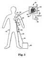
[0040]図1には、後方下方から見た、人間の心臓10が示されている。左心房12は、アブレートすべき組織領域を含む、領域のターゲット組織15の外面14を有する。幾つかの実施の形態において、ターゲット組織15は、肺静脈の回りを伸びるが、肺静脈を含まない左心房の全後壁組織として画成することができる。図1に示すように、ターゲット組織15は、全体として、肺静脈16から隔てられて肺静脈16への損傷を防止することができる。 [0040] In FIG. 1, a
[0041]図2に示すように、左心房12の内室22は、ターゲット組織15の内面24を含む。肺静脈16自体は、全体として、静脈の狭窄を懸念してターゲット組織15内に含まれない。ターゲット組織15の内面24は、肺静脈16を取り囲む、心門領域内に伸びるが、肺静脈の内腔までは伸びず、僧帽弁の輪付近まで伸びる全左心房後壁として画成することができる。右下方肺静脈の一方又は双方と僧帽弁輪との間の領域内に伝導ブロック部を形成することは興味が持たれる。保護すべき組織は、ターゲット組織15として画成されない患者の全ての組織を含むことができる。保護すべき組織は、損傷を防止するため隔離することができる。ターゲット組織15は、肺静脈16の心門から隔てることができるが、同様に、肺静脈心門を取り囲む領域まで伸びるようにしてもよい。 As shown in FIG. 2, the
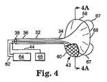
[0042]図3には、ターゲット組織15をアブレートする、本発明の1つの実施の形態に従ったアブレーション装置30が示されている。該アブレーション装置30は、トロカール、内視鏡ポート、カテーテル等のような、挿入ツール32を含み又は挿入ツール32と共に使用することができる。挿入ツール32は、末端34と、基端36とを含むことができる。アブレーション装置30はまた、挿入ツール32を通って伸び且つ、挿入ツール32の末端34及び(又は)基端36にて開くことのできる管腔38を含めることもできる。アブレーション装置30は、挿入ツール32の末端34から伸びることのできるアブレータ43を更に含むことができる。アブレータ43は、患者42の切開部40を通して送り出すため、管腔38内に挿入することができる。導体44は、管腔38を貫通して伸びてアブレータ43を電源46と接続することができる。電源46は、高周波エネルギのようなアブレーションエネルギ源とすることができる。その他の形態のアブレーション方法及びエネルギ源をアブレータ43と共に使用することができる。アブレーション技術のその他の形態は、マイクロ波、超音波、熱、低温、放射線及び化学的アブレーションを含むが、これらにのみ限定されるものではない。 [0042] In FIG. 3, an
[0043]アブレータ43をターゲット組織15上に適正に配置することは、直接可視化、蛍光透視X線可視化、超音波陽子放出断層撮影、蛍光透視、心臓内エコー、経食道エコー、磁気共鳴画像法、コンピュータ断層撮影、又は内視鏡画像法のような任意の適宜な手段により実行することができる。図3に示すように、マッピングツール48は、ターゲット組織15に対するアブレータ43の位置を表し又は可視化すべくディスプレイ52と接続されたセンサ50を含むことができる。トグルスティック54又はポインタペン56のような入力装置を使用して心臓10にてターゲット組織15を識別することができる。[0044]アブレータ34は、組織係合部分60(図4ないし図6に図示)を含むことができ、該組織係合部分60は、組織係合部分60が各励起により所定の領域をアブレートすることを許容するフートプリントを含むことができる。 [0043] Proper placement of the
[0045]図4に示すように、アブレータ43は、心内膜又は心外膜の取り付けのためフートプリントを有する組織係合部分60を備えるバルーン58を含むことができる。フートプリントは、患者個人の必要性に順応し得る寸法及び形状とすることができる。バルーン58は、挿入ツール32内に配置されたインフレータ管62を含むことができる。インフレータ管62は、拡張源64と接続してバルーン58を空気、CO2、食塩水等にて拡張させることができる。バルーン58における絶縁体66は、組織係合部分60のフートプリントに対して圧接するターゲット組織15をアブレートする間、隣接する組織をアブレータ43内にてエネルギから保護することができる。バルーン58内の食塩水又は気体によって追加的な絶縁を実現することができる。[0045] As shown in FIG. 4, the
挿入ツール32は、可撓性又は剛性とし、外科医がバルーン58の位置を操作して組織係合部分60をターゲット組織15と接触させるのを助けることができる。拡張源64は、液体又は気体をインフレータ管62を通して導き、バルーン58を拡張させることができる。バルーン58は、拡張して組織係合部分60がターゲット組織15に対して圧接するようにすることができる。幾つかの実施の形態において、図4に示すように、屈曲するストラッツ67は、左心房12内に配設してアブレータ43を押し左心房の後壁と接触させることができる。心膜腔内に配設されたとき、バルーン58は、拡張させて組織係合部分60を心外膜のターゲット組織15と強制的に接触させることができる。 The
[0046]幾つかの実施の形態において、バルーン58は、組織係合部分60として作用する伝導面を含むことができる。萎んだバルーン58は、左心房12内に又はターゲット組織15の心外膜面を取り囲む心膜腔内に挿入することができる。1つの実施の形態において、次に、バルーン58は、拡張源64からの食塩水にて拡張させ且つバルーン58の熱透過性の組織係合部分60を後左心房に対して配置し且つ、バルーン58の絶縁部分を前左心房に対して配置することができるよう向き決めすることができる。食塩水は、電源46により供給された電流によって50℃ないし80℃の範囲の温度、また、幾つかの実施の形態において、55℃ないし65℃の範囲まで加熱することができる。これらの温度のとき、ターゲット領域15内の細胞は、全体として、コラーゲンの収縮無しにて死滅する。これと代替的に、バルーン58は、低温技術により冷却して心房組織を凍結し且つターゲット組織15をアブレートするようにしてもよい。全体として、低温治療のための温度は、−20℃以下ないし−40℃の範囲でなければならない。 [0046] In some embodiments, the
[0047]図4には、アブレータ43を取り囲む絶縁体66を有するバルーン58の断面図が示されている。アブレータ43は、電源46のエネルギをターゲット組織15に伝送すべく組織係合部分60に1つ又はより多くのアブレーティング要素68を含むことができる。アブレーティング要素68は、例えば、1つ又はより多くの電極、超音波トランスデューサ、マイクロ波アンテナ、低温要素、化学的要素及び(又は)放射性要素を備えることができる。バルーン58を左心房12内に挿入することは、拡張する間、バルーン58を操作して組織係合部分60のアブレーティング要素68をターゲット組織15に対して圧接し且つアブレーティング要素68を保護すべき組織から隔てることを許容する。絶縁体66は、ターゲット組織15の領域内に無い隣接する組織を保護することができる。 [0047] In FIG. 4, a cross-sectional view of a
[0048]アブレータ43は、図4Bに示すように、カテーテル70のような挿入ツール32を使用して患者の体内の所望の位置まで送り出すことができる。アブレータ43のフートプリントは、任意の患者の解剖学的形態及び(又は)所望の任意のアブレーションパターンに合った形態とすることができる。アブレータ43の萎んだバルーン58は、カテーテル70の末端34を通して除去可能に挿入し、導体44が図4Bに示すように挿入ツール32を貫通して伸びるようにすることができる。カテーテル70は、患者42の体内に挿入し(図3に関して説明したように)、末端34をターゲット組織15に隣接する位置に配置することができる。図4に示すように、導体44を使用してアブレータ43を管腔38から末端34から伸びる位置まで押し出すことができる。 [0048] The
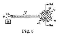
[0049]図5及び図5Aには、円形のアブレータ43の1つの実施の形態が示されている。その他の実施の形態において、アブレータ43は、楕円形、長円形等とすることができる。円形のアブレータ43は、組織係合面60と、外側スカート部72とを含むことができる。外側スカート部72は、組織係合面60を肺静脈16のような傷付き易い組織から隔てるための分離片として使用することができる。円形のアブレータ43は、組織係合面60に1つ又はより多くのアブレーティング要素68を有しており、また、図5Aに示すように、反対面に絶縁層66を有することができる。アブレーティング要素68は、ら旋形又は円形のパターンにて配置することができる。外側スカート部72は、シリコーン又はその他のエラストマー的材料のような柔軟で熱絶縁性の材料にて製造することができる。外側スカート部72は、アブレーティング要素68を保護すべき組織から確実に隔てるため、弾性的な材料で出来た外端縁74を含むことができる。 [0049] In FIG. 5 and FIG. 5A, one embodiment of a
[0050]円形のアブレータ43は、後左心房に隣接する心膜腔内に挿入することにより心外膜にて使用することができる。1つの実施の形態において、円形のアブレータ43は、代替的に、非コイル状のら旋状形態を含むようにしてもよい。非コイル状のら旋体は、シース32を通じて配置することができ、また、シース32を超えて前進したとき、非コイル状となり所望の形状をとることができる。NiTiのような予め形成した形状記憶合金又は超弾性合金を使用してら旋体が非コイル状となり所望の形状となることを保証することができる。 [0050] The
[0051]別の実施の形態において、2つの円形のアブレータ43を双極の配置にて使用することができる。1つのアブレータ43は、ターゲット組織15の外面14上にあり、別のアブレータ43は、左心房12のターゲット組織15の内面24上に位置するようにする。円形の双極アブレータ43は、非コイル状のら旋形態を使用して配置することができる。非コイル状のら旋体は、シース32を通して配置し、また、シース32を超えて前進したとき、非コイル状となって所望の形状をとることができる。ら旋体が非コイル状となって所望の形状となるのを保証すべく、NiTiのような予め形成した形状記憶合金又は超弾性合金を使用することができる。 [0051] In another embodiment, two
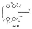
[0052]図6及び図15には、湾曲した端縁76を有する所定の形状の湾曲型パッチアブレータ43の2つの実施の形態が示されている。湾曲した端縁76は、肺静脈16のような心臓内の構造体に対して圧接し、組織係合面60をターゲット組織15に対して配置することができる。図6に示すように、アブレーティング要素68は、心外膜又は心内膜に取り付ける双方のため挿入ツール32を貫通して伸びる導体44によって電源46と接続することができる。 [0052] In FIGS. 6 and 15, two embodiments of a pre-shaped
[0053]図7には、第一のアブレーティング要素80と、第二のアブレーティング要素82という2つのアブレーティング要素を有するアブレータ43が示されている。導体44を使用して、第一及び第二のアブレーティング要素80、82を共に又は別個に接続して個別に制御することができる。1つの実施の形態において、アブレーティング要素80、82は、高周波エネルギを使用して励起させることができる電極を備えることができる。アブレーティング要素80、82は、ポート83に付与された真空圧により組織と接触した状態に保持することができる。これと代替的に、第一のアブレーティング要素80は、高強度に収束された超音波(HIFU)クリスタル送信機又はトランスデューサとし、また、第二のアブレーティング要素82は、別のHIFUクリスタル送信機又はトランスデューサとしてもよく、その双方は、超音波エネルギをターゲット組織15に収束させる。これと代替的に、第一及び第二のアブレーティング要素80、82は、マイクロ波アブレーションエネルギをターゲット組織15まで送り出すことができるマイクロ波アンテナとしてもよい。幾つかの実施の形態において、食道内の位置からアブレーションエネルギを心臓の後左心房に収束させるべくアブレータ43を使用することができる。 [0053] In FIG. 7, an
[0054]図8には、スカート部73と、患者の体内に配置してターゲット組織15を取り囲むことができる配設可能なワイパ86とを有するアブレータ43が示されている。スカート部73は、吸引チャンバ84に付与された真空圧によりターゲット組織15に対して保持することができる。配設可能なワイパ86は、導体44と接続し且つ、アブレータ43のスカート部73内を動いて回動点(例えば、モータ88)の回りを円弧状に回転することができる。配設可能なワイパ86は、1つ又はより多くのアブレーティング要素を含むことができる。配設可能なワイパ86は、側部から側部に掃き払い且つ(又は)360°回転し且つ、回転する間又は回転する一部分の間、エネルギを付与してアブレートする。スカート部73はカテーテル70内に除去可能に挿入し得るよう折り畳むことができる。弾性的な外端縁74は、真空圧が付与されたとき、ターゲット組織15に解放可能に密封することができる。スカート部73と配設可能なワイパ86との間の空隙は、隣接する組織をアブレーションエネルギによる損傷から保護する。また、アブレーションをスカート部73内にて案内するのを助けるため、導体44に隣接して管腔を提供し光ファイバ又は内視鏡型カテーテルが通るのを許容し、このことは、スカート部73及びアブレーションのため選んだ領域の適正な位置を視覚的に確認することができる。 [0054] FIG. 8 shows an
[0055]図9には、カテーテル70から伸びるフートプリントを有する接着剤舌状体90を含むアブレータ43が示されている。スカート部72を使用して外端縁74内の組織をアブレートすることができる。接着剤舌状体90は、ターゲット組織15に除去可能に取り付けて導体44を通して付与された真空圧により指向性アブレーションをすることができる。その他の実施の形態において、組織係合面60における生物適合可能な糊又は接着剤91により接触させ易くすることができる。スカート部72のチャンバ84内にて伝導性流体92を使用してアブレーティングエネルギを外端縁74内の全ての組織に伝達することができる。これと代替的に、解放速度の遅いアブレーション化学剤により接着剤絶縁体90を心外膜に取り付けて組織をアブレートすることができる。接着剤舌状体90はまた、幾つかの実施の形態において、抗不整脈薬剤又はその他の薬剤を含むようにしてもよい。 [0055] In FIG. 9, an
[0056]図10には、例えば、化学的アブレーション剤及び(又は)放射性アブレーション剤のような1つ又はより多くのアブレーション剤を送り出す設計とされたアブレータ43が示されている。導体又は導管44は、アブレーティブ剤を先端96を通して運びスカート部72の外端縁74内にて組織と接触するようにすることができる。先端96は、左心房内に配置されるようカテーテル70内に除去可能に挿入することができる。カテーテル70は、操作し且つ回転させてスカート部72がターゲット組織15を覆うようにすることができる。アブレーション剤は、スカート部72内にてチャンバ84内に導入しターゲット組織15をアブレートすることができる。アブレーション手順の後、残留する全てのアブレーション剤を先端96を通して除去することができる。幾つかの実施の形態において、先端96は、アブレーション剤を組織内に機械的に注射し及び(又は)無針注射し得る設計とすることができる。1つの実施の形態において、アブレーション剤は治療すべき組織内に拡散する。これと代替的に、アブレーション剤は、解放速度が遅いよう制御された送り出し及び(又は)イオン導入技術を介して送り出されるようにしてもよい。 [0056] FIG. 10 shows an
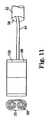
[0057]図11には、単一のロール又は平行なロールとなるようにロール状にすることができ、また、挿入ツール32内に除去可能に挿入することのできるロール状アブレーティング要素98を含むアブレータ43が示されている。S字形の記憶ワイヤー100は、導体44がロール状アブレーティング要素98を管腔38から押し出すとき、ロール状アブレーティング要素98を非ロール状にしてもよい。ロール状アブレーティング要素98は、ロール状にして心臓10と心膜との間に配置しターゲット組織15の外面14まで心外膜アブレーションすることができる。ロール状アブレーティング要素98は、図5及び図6に示した円形で且つ湾曲した実施の形態にそれぞれ類似したものとすることができる。 [0057] In FIG. 11, a rolled ablating
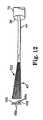
[0058]図12には、折り重ね部106の各々の頂点104に配置されたアブレーティング要素68a、68bを有するウェブ付きファン102を含むアブレータ43が示されている。アブレーティング要素68aは、ターゲット組織15に隣接して配置されたとき、励起させることができ、また、ターゲット組織15から隔てられたアブレーティング要素68bは、非励起状態に止まりターゲット組織15の領域外の組織を保護することができる。ウェブ付きファン102は、一側部に絶縁層を含むことができる。ウェブ付きファン102は、展開させて平坦なシートにしアブレーティング要素68a、68bの全て又は一部分を励起させることができる。ウェブ付きファン102は、カテーテル70の管腔38内に除去可能に挿入し得るよう圧縮することができる。 [0058] In FIG. 12, an
[0059]図13A及び図13Bには、多数のアブレーティング要素68を有する拡張可能な金網を備えるアブレータ43が示されている。アブレータ43は、挿入ツール32を使用して左心房内に配置することができる。アブレーティング要素68の各々は、マッピングツール48を使用して個々に表わすことができ、また、ディスプレイ52に表示してもよい。導体44は、ターゲット組織15と接触した個々の電極68を電源46により励起させて組織をアブレートすることを許容する。1つ又はより多くのセンサ50を拡張可能な金網内に配置してターゲット組織15の位置を探知することができる。後左心房と接触する拡張可能な金網におけるアブレーティング要素68を選ぶことができる。この選択は、電気生理学的マッピング、コンピュータ利用の複雑なアルゴリズム、画像化、高性能なアブレーティング要素68の個別の操作又はその他の適宜な方法により容易にすることができる。適宜なアブレーティング要素68は、個々に又は全体的に励起させ、後部にアブレートした組織の領域を形成することができる。 [0059] In FIGS. 13A and 13B, an
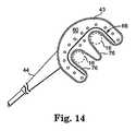
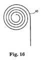
[0060]図14には、湾曲した端縁76により画成された所定の形状を有する湾曲型アブレータ43が示されている。湾曲した端縁76は、肺静脈16のような心臓の構造体に対して圧接し組織係合面60をターゲット組織15に対して配置することができる。1つ又はより多くのアブレーティング要素68を、導体44により電源(図示せず)と接続することができる。[0061]図16には、挿入ツール32(例えば、シース)から配設してアブレートするための領域を形成することのできる1つ又はより多くのコイル状アブレーティング要素を有するコイル状線形アブレータ43が示されている。幾つかの実施の形態において、コイル状線形アブレータ43は、エネルギを一方向に(例えば、後左心房の心外膜面に向けて)送り出すことができる。 FIG. 14 shows a
[0062]幾つかの実施の形態において、アブレータ43(例えば、1つ又はより多くのアブレーティング要素を有するアブレーションエネルギの伝送部材)は、ターゲット組織15から遠方にあるようにすることができる。例えば、超音波エネルギを遠方からターゲット組織15に収束させ、ターゲット組織とアブレータ43との間に配置された非ターゲット組織をアブレートせずに通過する間、ターゲット組織15をアブレーションすることができる。ターゲット組織15におけるエネルギの収束位置は、アブレートすべき非線状領域の回りの収束点をステアリングすることにより、アブレートすべき領域の全体に亙って動かすことができる。ステアリング機構は手操作とし(例えば、超音波トランスデューサを組織に対して物理的に動かすことにより)又は電気式(例えば、超音波トランスデューサの位相配列を使用し又は超音波収束領域をその他の方法で変更することにより)とすることができる。 [0062] In some embodiments, the ablator 43 (eg, an ablation energy transmission member having one or more ablating elements) can be remote from the
[0063]本発明の幾つかの実施の形態は、心房細動を治療するのに効果的であり、しかも、幾つかの従来の方法よりも安全に実行することができる。本発明の幾つかの実施の形態は、幾つかの従来の方法よりも迅速にアブレーションを実行することができる。本発明の幾つかの実施の形態は、心臓の左心房付属器官(LAA)−多くの人の血栓及び発作の主要な発生源のようなーの切断、結紮、接合等を行うため使用することもできる。本発明の幾つかの実施の形態の結果、患者への外的損傷が減少し、また、心臓及びそれを取り巻く構造体を偶発的に損傷する機会が少なくなる。本発明の幾つかの実施の形態は、アブレーション装置30及び(又は)アブレータ43を胸壁を通して挿入するのに必要な切開部の寸法を最小限にすることができる。本発明の幾つかの実施の形態は、心房細動を治療するため隣接する線状の人工的病変部の必要性を解消することができる。本発明の幾つかの実施の形態は、外科医が拍動する心臓の心外膜面から心臓内に人工的病変部を形成することを許容することができる。本発明の幾つかの実施の形態は、心臓の内部から経静脈カテーテルを介して実施することができる。[0064]本発明の色々な追加的な特徴及び有利な効果は、特許請求の範囲に記載されている。 [0063] Some embodiments of the present invention are effective in treating atrial fibrillation and can be performed more safely than some conventional methods. Some embodiments of the present invention can perform ablation more quickly than some conventional methods. Some embodiments of the present invention may also be used to perform cutting, ligation, joining, etc. of the left atrial appendage (LAA) of the heart—a major source of thrombus and stroke in many people. it can. As a result of some embodiments of the present invention, external damage to the patient is reduced and the chances of accidental damage to the heart and surrounding structures are reduced. Some embodiments of the present invention can minimize the size of the incision required to insert the
Claims (28)
Translated fromJapanese組織係合部分を有するアブレータを備えるアブレーション装置を選ぶステップと、
患者の胸腔に侵入するステップと、
ターゲット組織を識別するステップと、
組織係合部分がアブレーションエネルギをターゲット組織に伝達することができるようにアブレーション装置をターゲット組織に隣接する位置に配置するステップと、
組織係合部分をアブレーションエネルギにて励起して左心房内の組織の非線状領域にフートプリントを形成し且つ左心房内の励起可能な組織の全質量を減少させるステップとを備える、ターゲット組織をアブレートする方法。In a method of ablating a target tissue comprising a non-linear region of tissue within a patient's left atrium,
Selecting an ablation device comprising an ablator having a tissue engaging portion;
Entering the patient's chest cavity;
Identifying the target organization;
Positioning the ablation device adjacent to the target tissue so that the tissue engaging portion can transmit ablation energy to the target tissue;
Exciting the tissue engaging portion with ablation energy to form a footprint in a non-linear region of tissue in the left atrium and reducing the total mass of excitable tissue in the left atrium. How to ablate.
アブレーション装置を挿入ツールの送り出し端部内に除去可能に配置するステップと、
挿入ツールを切開部を通して患者の体内に配置するステップと、
送り出し端部をターゲット組織に隣接する位置に導くステップと、
アブレーション装置を挿入ツールから除去するステップと、
組織係合部分をターゲット組織と接触させ得るようにアブレーション装置を調節するステップとを更に備える、方法。The method of claim 1, wherein
Removably placing the ablation device within the delivery end of the insertion tool;
Placing an insertion tool through the incision into the patient's body;
Directing the delivery end to a location adjacent to the target tissue;
Removing the ablation device from the insertion tool;
Adjusting the ablation device to allow the tissue engaging portion to contact the target tissue.
基端、末端、管腔を有する挿入ツールと、
導体及び組織係合部分を有するアブレータであって、導体は挿入ツールの基端から伸びる供給端と、組織係合部分に連結された送り出し端部とを有し、管腔内に除去可能に挿入された前記アブレータと、
導体と接続されたエネルギ源と、
末端がターゲット組織に隣接するように患者の体内に挿入される挿入ツールと、
アブレータを管腔から外に押し出して、ターゲット組織と係合させる導体とを備え、
エネルギはエネルギ源からアブレータまで伝達されて、ターゲット組織にフートプリントを形成し、励起可能な組織の全質量を減少させるようにした、アブレーション装置。In an ablation device for ablating a patient's target tissue,
An insertion tool having a proximal end, a distal end, a lumen;
An ablator having a conductor and a tissue engaging portion, the conductor having a supply end extending from the proximal end of the insertion tool and a delivery end connected to the tissue engaging portion for removably insertion into the lumen Said ablator,
An energy source connected to the conductor;
An insertion tool that is inserted into the patient's body so that the distal end is adjacent to the target tissue;
A conductor that pushes the ablator out of the lumen and engages the target tissue;
An ablation device in which energy is transferred from the energy source to the ablator to form a foot print on the target tissue, reducing the total mass of excitable tissue.
Applications Claiming Priority (2)
| Application Number | Priority Date | Filing Date | Title |
|---|---|---|---|
| US57118204P | 2004-05-14 | 2004-05-14 | |
| PCT/US2005/016806WO2005112812A1 (en) | 2004-05-14 | 2005-05-13 | Method and devices for treating atrial fibrillation by mass ablation |
Publications (1)
| Publication Number | Publication Date |
|---|---|
| JP2007537011Atrue JP2007537011A (en) | 2007-12-20 |
Family
ID=34969568
Family Applications (1)
| Application Number | Title | Priority Date | Filing Date |
|---|---|---|---|
| JP2007513412APendingJP2007537011A (en) | 2004-05-14 | 2005-05-13 | Method and apparatus for treating atrial fibrillation by reducing mass |
Country Status (8)
| Country | Link |
|---|---|
| US (3) | US20060009756A1 (en) |
| EP (1) | EP1750605B1 (en) |
| JP (1) | JP2007537011A (en) |
| AT (2) | ATE547990T1 (en) |
| AU (1) | AU2005244868A1 (en) |
| CA (1) | CA2569701A1 (en) |
| ES (1) | ES2308505T3 (en) |
| WO (1) | WO2005112812A1 (en) |
Cited By (1)
| Publication number | Priority date | Publication date | Assignee | Title |
|---|---|---|---|---|
| JP2010510826A (en)* | 2006-11-28 | 2010-04-08 | コーニンクレッカ フィリップス エレクトロニクス エヌ ヴィ | Apparatus, method and computer program for applying energy to object |
Families Citing this family (163)
| Publication number | Priority date | Publication date | Assignee | Title |
|---|---|---|---|---|
| US5897553A (en) | 1995-11-02 | 1999-04-27 | Medtronic, Inc. | Ball point fluid-assisted electrocautery device |
| US6409722B1 (en)* | 1998-07-07 | 2002-06-25 | Medtronic, Inc. | Apparatus and method for creating, maintaining, and controlling a virtual electrode used for the ablation of tissue |
| NL1003024C2 (en)* | 1996-05-03 | 1997-11-06 | Tjong Hauw Sie | Stimulus conduction blocking instrument. |
| US6096037A (en)* | 1997-07-29 | 2000-08-01 | Medtronic, Inc. | Tissue sealing electrosurgery device and methods of sealing tissue |
| US6537248B2 (en)* | 1998-07-07 | 2003-03-25 | Medtronic, Inc. | Helical needle apparatus for creating a virtual electrode used for the ablation of tissue |
| US6706039B2 (en)* | 1998-07-07 | 2004-03-16 | Medtronic, Inc. | Method and apparatus for creating a bi-polar virtual electrode used for the ablation of tissue |
| US8221402B2 (en)* | 2000-01-19 | 2012-07-17 | Medtronic, Inc. | Method for guiding a medical device |
| US6692450B1 (en)* | 2000-01-19 | 2004-02-17 | Medtronic Xomed, Inc. | Focused ultrasound ablation devices having selectively actuatable ultrasound emitting elements and methods of using the same |
| US6447443B1 (en) | 2001-01-13 | 2002-09-10 | Medtronic, Inc. | Method for organ positioning and stabilization |
| US6595934B1 (en)* | 2000-01-19 | 2003-07-22 | Medtronic Xomed, Inc. | Methods of skin rejuvenation using high intensity focused ultrasound to form an ablated tissue area containing a plurality of lesions |
| US8241274B2 (en) | 2000-01-19 | 2012-08-14 | Medtronic, Inc. | Method for guiding a medical device |
| US7706882B2 (en) | 2000-01-19 | 2010-04-27 | Medtronic, Inc. | Methods of using high intensity focused ultrasound to form an ablated tissue area |
| US8048070B2 (en) | 2000-03-06 | 2011-11-01 | Salient Surgical Technologies, Inc. | Fluid-assisted medical devices, systems and methods |
| ES2306706T3 (en)* | 2000-03-06 | 2008-11-16 | Salient Surgical Technologies, Inc. | FLUID SUPPLY SYSTEM AND CONTROLLER FOR ELECTROCHURGICAL DEVICES. |
| US6488680B1 (en) | 2000-04-27 | 2002-12-03 | Medtronic, Inc. | Variable length electrodes for delivery of irrigated ablation |
| US6514250B1 (en) | 2000-04-27 | 2003-02-04 | Medtronic, Inc. | Suction stabilized epicardial ablation devices |
| AU2001249874A1 (en)* | 2000-04-27 | 2001-11-12 | Medtronic, Inc. | System and method for assessing transmurality of ablation lesions |
| DE60111517T2 (en)* | 2000-04-27 | 2006-05-11 | Medtronic, Inc., Minneapolis | VIBRATION-SENSITIVE ABLATION DEVICE |
| US6926669B1 (en)* | 2000-10-10 | 2005-08-09 | Medtronic, Inc. | Heart wall ablation/mapping catheter and method |
| US7628780B2 (en)* | 2001-01-13 | 2009-12-08 | Medtronic, Inc. | Devices and methods for interstitial injection of biologic agents into tissue |
| US7740623B2 (en)* | 2001-01-13 | 2010-06-22 | Medtronic, Inc. | Devices and methods for interstitial injection of biologic agents into tissue |
| US20040138621A1 (en) | 2003-01-14 | 2004-07-15 | Jahns Scott E. | Devices and methods for interstitial injection of biologic agents into tissue |
| US7250048B2 (en) | 2001-04-26 | 2007-07-31 | Medtronic, Inc. | Ablation system and method of use |
| US7959626B2 (en) | 2001-04-26 | 2011-06-14 | Medtronic, Inc. | Transmural ablation systems and methods |
| US6699240B2 (en)* | 2001-04-26 | 2004-03-02 | Medtronic, Inc. | Method and apparatus for tissue ablation |
| US6807968B2 (en)* | 2001-04-26 | 2004-10-26 | Medtronic, Inc. | Method and system for treatment of atrial tachyarrhythmias |
| US6648883B2 (en)* | 2001-04-26 | 2003-11-18 | Medtronic, Inc. | Ablation system and method of use |
| US6663627B2 (en) | 2001-04-26 | 2003-12-16 | Medtronic, Inc. | Ablation system and method of use |
| WO2002094363A2 (en) | 2001-05-21 | 2002-11-28 | Medtronic,Inc. | Trans-septal catheter with retention mechanism |
| EP1435867B1 (en) | 2001-09-05 | 2010-11-17 | Salient Surgical Technologies, Inc. | Fluid-assisted medical devices and systems |
| US6656175B2 (en)* | 2001-12-11 | 2003-12-02 | Medtronic, Inc. | Method and system for treatment of atrial tachyarrhythmias |
| US7967816B2 (en) | 2002-01-25 | 2011-06-28 | Medtronic, Inc. | Fluid-assisted electrosurgical instrument with shapeable electrode |
| US20080275439A1 (en)* | 2002-01-25 | 2008-11-06 | David Francischelli | Cardiac ablation and electrical interface system and instrument |
| US6827715B2 (en)* | 2002-01-25 | 2004-12-07 | Medtronic, Inc. | System and method of performing an electrosurgical procedure |
| US7118566B2 (en) | 2002-05-16 | 2006-10-10 | Medtronic, Inc. | Device and method for needle-less interstitial injection of fluid for ablation of cardiac tissue |
| US7294143B2 (en)* | 2002-05-16 | 2007-11-13 | Medtronic, Inc. | Device and method for ablation of cardiac tissue |
| US7083620B2 (en)* | 2002-10-30 | 2006-08-01 | Medtronic, Inc. | Electrosurgical hemostat |
| US7497857B2 (en)* | 2003-04-29 | 2009-03-03 | Medtronic, Inc. | Endocardial dispersive electrode for use with a monopolar RF ablation pen |
| US8333764B2 (en)* | 2004-05-12 | 2012-12-18 | Medtronic, Inc. | Device and method for determining tissue thickness and creating cardiac ablation lesions |
| JP2007537011A (en) | 2004-05-14 | 2007-12-20 | メドトロニック・インコーポレーテッド | Method and apparatus for treating atrial fibrillation by reducing mass |
| WO2005120374A1 (en)* | 2004-06-02 | 2005-12-22 | Medtronic, Inc. | Compound bipolar ablation device and method |
| ATE516762T1 (en)* | 2004-06-02 | 2011-08-15 | Medtronic Inc | ABLATION AND STAPLE INSTRUMENT |
| EP1750607A2 (en)* | 2004-06-02 | 2007-02-14 | Medtronic, Inc. | Loop ablation apparatus and method |
| WO2005120376A2 (en) | 2004-06-02 | 2005-12-22 | Medtronic, Inc. | Ablation device with jaws |
| US20100145331A1 (en)* | 2004-06-02 | 2010-06-10 | Chrisitian Steven C | Loop Ablation Apparatus and Method |
| US8926635B2 (en)* | 2004-06-18 | 2015-01-06 | Medtronic, Inc. | Methods and devices for occlusion of an atrial appendage |
| EP1768575B1 (en)* | 2004-06-18 | 2019-01-16 | Medtronic, Inc. | Devices for occlusion of an atrial appendage |
| US8663245B2 (en) | 2004-06-18 | 2014-03-04 | Medtronic, Inc. | Device for occlusion of a left atrial appendage |
| US8409219B2 (en) | 2004-06-18 | 2013-04-02 | Medtronic, Inc. | Method and system for placement of electrical lead inside heart |
| US9055942B2 (en)* | 2005-10-03 | 2015-06-16 | Boston Scienctific Scimed, Inc. | Endoscopic plication devices and methods |
| US7744591B2 (en)* | 2005-12-29 | 2010-06-29 | Boston Scientific Scimed, Inc. | Foam electrode and method of use thereof during tissue resection |
| WO2007089675A2 (en)* | 2006-01-27 | 2007-08-09 | Medtronic, Inc. | Ablation device and system for guiding said ablation device into a patient's body |
| US7749249B2 (en) | 2006-02-21 | 2010-07-06 | Kardium Inc. | Method and device for closing holes in tissue |
| US20070270688A1 (en) | 2006-05-19 | 2007-11-22 | Daniel Gelbart | Automatic atherectomy system |
| US20080039746A1 (en)* | 2006-05-25 | 2008-02-14 | Medtronic, Inc. | Methods of using high intensity focused ultrasound to form an ablated tissue area containing a plurality of lesions |
| US10028783B2 (en) | 2006-06-28 | 2018-07-24 | Kardium Inc. | Apparatus and method for intra-cardiac mapping and ablation |
| US11389232B2 (en) | 2006-06-28 | 2022-07-19 | Kardium Inc. | Apparatus and method for intra-cardiac mapping and ablation |
| US8920411B2 (en)* | 2006-06-28 | 2014-12-30 | Kardium Inc. | Apparatus and method for intra-cardiac mapping and ablation |
| US9814511B2 (en) | 2006-06-28 | 2017-11-14 | Medtronic Cryocath Lp | Variable geometry cooling chamber |
| US8449605B2 (en) | 2006-06-28 | 2013-05-28 | Kardium Inc. | Method for anchoring a mitral valve |
| US9119633B2 (en) | 2006-06-28 | 2015-09-01 | Kardium Inc. | Apparatus and method for intra-cardiac mapping and ablation |
| US7837610B2 (en) | 2006-08-02 | 2010-11-23 | Kardium Inc. | System for improving diastolic dysfunction |
| GB0620061D0 (en) | 2006-10-10 | 2006-11-22 | Medical Device Innovations Ltd | Oesophageal treatment apparatus and method |
| US20100094129A1 (en)* | 2006-12-20 | 2010-04-15 | Frank Marchilinski | Esophagial visualization device |
| US20080188714A1 (en)* | 2007-02-07 | 2008-08-07 | Boston Scientific Scimed, Inc. | Electromechanical in-situ cleaning of optical elements |
| US8906011B2 (en) | 2007-11-16 | 2014-12-09 | Kardium Inc. | Medical device for use in bodily lumens, for example an atrium |
| US8882756B2 (en)* | 2007-12-28 | 2014-11-11 | Medtronic Advanced Energy Llc | Fluid-assisted electrosurgical devices, methods and systems |
| US20090171346A1 (en)* | 2007-12-28 | 2009-07-02 | Greg Leyh | High conductivity inductively equalized electrodes and methods |
| US8489172B2 (en)* | 2008-01-25 | 2013-07-16 | Kardium Inc. | Liposuction system |
| US20090287304A1 (en)* | 2008-05-13 | 2009-11-19 | Kardium Inc. | Medical Device for Constricting Tissue or a Bodily Orifice, for example a mitral valve |
| US8172835B2 (en) | 2008-06-05 | 2012-05-08 | Cutera, Inc. | Subcutaneous electric field distribution system and methods |
| US20090306647A1 (en)* | 2008-06-05 | 2009-12-10 | Greg Leyh | Dynamically controllable multi-electrode apparatus & methods |
| US20100022999A1 (en)* | 2008-07-24 | 2010-01-28 | Gollnick David A | Symmetrical rf electrosurgical system and methods |
| US8382753B2 (en) | 2008-10-21 | 2013-02-26 | Hermes Innovations, LLC | Tissue ablation methods |
| US9662163B2 (en) | 2008-10-21 | 2017-05-30 | Hermes Innovations Llc | Endometrial ablation devices and systems |
| US8821486B2 (en) | 2009-11-13 | 2014-09-02 | Hermes Innovations, LLC | Tissue ablation systems and methods |
| US8197477B2 (en) | 2008-10-21 | 2012-06-12 | Hermes Innovations Llc | Tissue ablation methods |
| US8540708B2 (en) | 2008-10-21 | 2013-09-24 | Hermes Innovations Llc | Endometrial ablation method |
| US8500732B2 (en) | 2008-10-21 | 2013-08-06 | Hermes Innovations Llc | Endometrial ablation devices and systems |
| US8197476B2 (en) | 2008-10-21 | 2012-06-12 | Hermes Innovations Llc | Tissue ablation systems |
| US9254168B2 (en)* | 2009-02-02 | 2016-02-09 | Medtronic Advanced Energy Llc | Electro-thermotherapy of tissue using penetrating microelectrode array |
| EP2398416B1 (en) | 2009-02-23 | 2015-10-28 | Medtronic Advanced Energy LLC | Fluid-assisted electrosurgical device |
| WO2010144402A2 (en)* | 2009-06-08 | 2010-12-16 | Surgivision, Inc. | Mri-guided surgical systems with preset scan planes |
| CN102625670B (en)* | 2009-06-16 | 2015-07-15 | 核磁共振成像介入技术有限公司 | MRI-guided devices and MRI-guided interventional systems that can track and generate dynamic visualizations of the devices in near real time |
| US9345541B2 (en)* | 2009-09-08 | 2016-05-24 | Medtronic Advanced Energy Llc | Cartridge assembly for electrosurgical devices, electrosurgical unit and methods of use thereof |
| WO2011041571A2 (en) | 2009-10-01 | 2011-04-07 | Kardium Inc. | Medical device, kit and method for constricting tissue or a bodily orifice, for example, a mitral valve |
| US8715278B2 (en)* | 2009-11-11 | 2014-05-06 | Minerva Surgical, Inc. | System for endometrial ablation utilizing radio frequency |
| US11896282B2 (en) | 2009-11-13 | 2024-02-13 | Hermes Innovations Llc | Tissue ablation systems and method |
| US9289257B2 (en) | 2009-11-13 | 2016-03-22 | Minerva Surgical, Inc. | Methods and systems for endometrial ablation utilizing radio frequency |
| US8529562B2 (en) | 2009-11-13 | 2013-09-10 | Minerva Surgical, Inc | Systems and methods for endometrial ablation |
| EP2544616B1 (en) | 2010-03-11 | 2017-09-06 | Medtronic Advanced Energy LLC | Bipolar electrosurgical cutter with position insensitive return electrode contact |
| AU2011241103A1 (en) | 2010-04-13 | 2012-11-08 | Sentreheart, Inc. | Methods and devices for treating atrial fibrillation |
| US20110295249A1 (en)* | 2010-05-28 | 2011-12-01 | Salient Surgical Technologies, Inc. | Fluid-Assisted Electrosurgical Devices, and Methods of Manufacture Thereof |
| US9138289B2 (en) | 2010-06-28 | 2015-09-22 | Medtronic Advanced Energy Llc | Electrode sheath for electrosurgical device |
| US8920417B2 (en) | 2010-06-30 | 2014-12-30 | Medtronic Advanced Energy Llc | Electrosurgical devices and methods of use thereof |
| US8906012B2 (en) | 2010-06-30 | 2014-12-09 | Medtronic Advanced Energy Llc | Electrosurgical devices with wire electrode |
| US8956348B2 (en) | 2010-07-21 | 2015-02-17 | Minerva Surgical, Inc. | Methods and systems for endometrial ablation |
| US8940002B2 (en) | 2010-09-30 | 2015-01-27 | Kardium Inc. | Tissue anchor system |
| US9023040B2 (en) | 2010-10-26 | 2015-05-05 | Medtronic Advanced Energy Llc | Electrosurgical cutting devices |
| US9510897B2 (en) | 2010-11-05 | 2016-12-06 | Hermes Innovations Llc | RF-electrode surface and method of fabrication |
| US9119647B2 (en)* | 2010-11-12 | 2015-09-01 | Covidien Lp | Apparatus, system and method for performing an electrosurgical procedure |
| US11259867B2 (en) | 2011-01-21 | 2022-03-01 | Kardium Inc. | High-density electrode-based medical device system |
| US9452016B2 (en) | 2011-01-21 | 2016-09-27 | Kardium Inc. | Catheter system |
| US9480525B2 (en) | 2011-01-21 | 2016-11-01 | Kardium, Inc. | High-density electrode-based medical device system |
| CA2764494A1 (en) | 2011-01-21 | 2012-07-21 | Kardium Inc. | Enhanced medical device for use in bodily cavities, for example an atrium |
| US9427281B2 (en) | 2011-03-11 | 2016-08-30 | Medtronic Advanced Energy Llc | Bronchoscope-compatible catheter provided with electrosurgical device |
| US9072511B2 (en) | 2011-03-25 | 2015-07-07 | Kardium Inc. | Medical kit for constricting tissue or a bodily orifice, for example, a mitral valve |
| US20130066308A1 (en)* | 2011-08-31 | 2013-03-14 | Jaime Landman | Ablation-based therapy for bladder pathologies |
| AU2012312066C1 (en) | 2011-09-22 | 2016-06-16 | 460Medical, Inc. | Systems and methods for visualizing ablated tissue |
| US9014789B2 (en) | 2011-09-22 | 2015-04-21 | The George Washington University | Systems and methods for visualizing ablated tissue |
| US9750565B2 (en) | 2011-09-30 | 2017-09-05 | Medtronic Advanced Energy Llc | Electrosurgical balloons |
| US8870864B2 (en) | 2011-10-28 | 2014-10-28 | Medtronic Advanced Energy Llc | Single instrument electrosurgery apparatus and its method of use |
| USD777925S1 (en) | 2012-01-20 | 2017-01-31 | Kardium Inc. | Intra-cardiac procedure device |
| USD777926S1 (en) | 2012-01-20 | 2017-01-31 | Kardium Inc. | Intra-cardiac procedure device |
| EP2817061B1 (en) | 2012-02-24 | 2018-02-07 | Isolase, Ltd. | Improvements in ablation techniques for the treatment of atrial fibrillation |
| US9198592B2 (en) | 2012-05-21 | 2015-12-01 | Kardium Inc. | Systems and methods for activating transducers |
| US10827977B2 (en) | 2012-05-21 | 2020-11-10 | Kardium Inc. | Systems and methods for activating transducers |
| US9017321B2 (en) | 2012-05-21 | 2015-04-28 | Kardium, Inc. | Systems and methods for activating transducers |
| US9226792B2 (en) | 2012-06-12 | 2016-01-05 | Medtronic Advanced Energy Llc | Debridement device and method |
| US11234760B2 (en) | 2012-10-05 | 2022-02-01 | Medtronic Advanced Energy Llc | Electrosurgical device for cutting and removing tissue |
| WO2014106258A1 (en)* | 2012-12-31 | 2014-07-03 | Cold Plasma Medical Technologies, Inc. | Cold plasma electroporation of medication and associated methods |
| EP2769695A1 (en) | 2013-02-20 | 2014-08-27 | Cook Medical Technologies LLC | Expandable mesh platform for large area ablation |
| US9901394B2 (en) | 2013-04-04 | 2018-02-27 | Hermes Innovations Llc | Medical ablation system and method of making |
| US9907608B2 (en)* | 2013-09-05 | 2018-03-06 | Mitragen, Inc. | Valve treatment devices, systems, and methods |
| US10631914B2 (en) | 2013-09-30 | 2020-04-28 | Covidien Lp | Bipolar electrosurgical instrument with movable electrode and related systems and methods |
| US9649125B2 (en) | 2013-10-15 | 2017-05-16 | Hermes Innovations Llc | Laparoscopic device |
| EP4226881A1 (en) | 2013-10-31 | 2023-08-16 | AtriCure, Inc. | Device for left atrial appendage closure |
| JP6737705B2 (en) | 2013-11-14 | 2020-08-12 | ザ・ジョージ・ワシントン・ユニバーシティThe George Washingtonuniversity | Method of operating system for determining depth of injury site and system for generating images of heart tissue |
| JP2017500550A (en) | 2013-11-20 | 2017-01-05 | ザ・ジョージ・ワシントン・ユニバーシティThe George Washingtonuniversity | System and method for hyperspectral analysis of cardiac tissue |
| US10314647B2 (en) | 2013-12-23 | 2019-06-11 | Medtronic Advanced Energy Llc | Electrosurgical cutting instrument |
| US10813686B2 (en) | 2014-02-26 | 2020-10-27 | Medtronic Advanced Energy Llc | Electrosurgical cutting instrument |
| US9743972B2 (en) | 2014-07-18 | 2017-08-29 | Medtronic Cryocath Lp | Cardiac cryolipolysis for the treatment of cardiac arrhythmia |
| US9974599B2 (en) | 2014-08-15 | 2018-05-22 | Medtronic Ps Medical, Inc. | Multipurpose electrosurgical device |
| US9956029B2 (en) | 2014-10-31 | 2018-05-01 | Medtronic Advanced Energy Llc | Telescoping device with saline irrigation line |
| EP3215001A4 (en) | 2014-11-03 | 2018-04-04 | Luxcath, LLC | Systems and methods for assessment of contact quality |
| KR102499045B1 (en) | 2014-11-03 | 2023-02-10 | 더 조지 워싱턴 유니버시티 | Systems and methods for lesion assessment |
| US10722184B2 (en) | 2014-11-17 | 2020-07-28 | Kardium Inc. | Systems and methods for selecting, activating, or selecting and activating transducers |
| US10368936B2 (en) | 2014-11-17 | 2019-08-06 | Kardium Inc. | Systems and methods for selecting, activating, or selecting and activating transducers |
| US10492856B2 (en) | 2015-01-26 | 2019-12-03 | Hermes Innovations Llc | Surgical fluid management system and method of use |
| AU2016219980B2 (en) | 2015-02-18 | 2020-09-03 | Medtronic Xomed, Inc. | RF energy enabled tissue debridement device |
| US10188456B2 (en) | 2015-02-18 | 2019-01-29 | Medtronic Xomed, Inc. | Electrode assembly for RF energy enabled tissue debridement device |
| US10376302B2 (en) | 2015-02-18 | 2019-08-13 | Medtronic Xomed, Inc. | Rotating electrical connector for RF energy enabled tissue debridement device |
| CN107708591B (en) | 2015-04-29 | 2020-09-29 | 席勒斯科技有限公司 | Medical ablation device and method of use |
| US20180161039A1 (en)* | 2015-06-19 | 2018-06-14 | Koninklijke Philips N.V. | Implantable medical device and system to heat tissue |
| US10779904B2 (en) | 2015-07-19 | 2020-09-22 | 460Medical, Inc. | Systems and methods for lesion formation and assessment |
| US11389227B2 (en) | 2015-08-20 | 2022-07-19 | Medtronic Advanced Energy Llc | Electrosurgical device with multivariate control |
| US11051875B2 (en) | 2015-08-24 | 2021-07-06 | Medtronic Advanced Energy Llc | Multipurpose electrosurgical device |
| US10716612B2 (en) | 2015-12-18 | 2020-07-21 | Medtronic Advanced Energy Llc | Electrosurgical device with multiple monopolar electrode assembly |
| US10052149B2 (en) | 2016-01-20 | 2018-08-21 | RELIGN Corporation | Arthroscopic devices and methods |
| CN109561899A (en) | 2016-04-22 | 2019-04-02 | 锐凌公司 | Arthroscope device and method |
| WO2017192510A2 (en) | 2016-05-02 | 2017-11-09 | Affera, Inc. | Pulsed radiofrequency ablation |
| CN109661209A (en) | 2016-07-01 | 2019-04-19 | 锐凌公司 | Arthroscope device and method |
| US10194975B1 (en) | 2017-07-11 | 2019-02-05 | Medtronic Advanced Energy, Llc | Illuminated and isolated electrosurgical apparatus |
| US12023082B2 (en) | 2017-10-06 | 2024-07-02 | Medtronic Advanced Energy Llc | Hemostatic thermal sealer |
| CN111801062B (en)* | 2018-02-21 | 2024-12-31 | 美敦力公司 | Focal pulsed field ablation device and method |
| US10686715B2 (en) | 2018-05-09 | 2020-06-16 | Biosig Technologies, Inc. | Apparatus and methods for removing a large-signal voltage offset from a biomedical signal |
| US20200038089A1 (en) | 2018-07-31 | 2020-02-06 | Ethicon, Inc. | Tissue resection apparatus |
| US11554214B2 (en) | 2019-06-26 | 2023-01-17 | Meditrina, Inc. | Fluid management system |
| WO2021126980A1 (en) | 2019-12-16 | 2021-06-24 | Affera, Inc. | Pulmonary vein isolation catheters and associated devices, systems, and methods |
| EP4087511A4 (en) | 2020-01-08 | 2024-02-14 | 460Medical, Inc. | Systems and methods for optical interrogation of ablation lesions |
| US20210338316A1 (en)* | 2020-04-30 | 2021-11-04 | Ethicon, Inc. | Systems and methods for sealing cored or punctured tissue using inflatable balloon |
| USD1014762S1 (en) | 2021-06-16 | 2024-02-13 | Affera, Inc. | Catheter tip with electrode panel(s) |
| CN114209419B (en)* | 2021-12-14 | 2024-07-05 | 上海交通大学医学院附属瑞金医院 | Ablation treatment equipment |
Citations (4)
| Publication number | Priority date | Publication date | Assignee | Title |
|---|---|---|---|---|
| JPH09503677A (en)* | 1993-07-01 | 1997-04-15 | ボストン・サイエンティフィック・コーポレーション | Imaging, Potential Sensing and Ablation Catheter |
| JP2003319945A (en)* | 2002-03-22 | 2003-11-11 | Ethicon Endo Surgery Inc | Medical device used for bodily organ of patient and attaching method of the same |
| JP2004500917A (en)* | 2000-04-27 | 2004-01-15 | メドトロニック・インコーポレーテッド | Suction-stabilized epicardial resection device |
| JP2004522544A (en)* | 2001-03-07 | 2004-07-29 | ボストン サイエンティフィック リミテッド | Internal indifferent electrode |
Family Cites Families (308)
| Publication number | Priority date | Publication date | Assignee | Title |
|---|---|---|---|---|
| US3823575A (en) | 1971-06-07 | 1974-07-16 | Univ Melbourne | Cryogenic apparatus |
| US3736936A (en) | 1971-12-13 | 1973-06-05 | Hughes Aircraft Co | Cryogenic heat transfer device |
| GB1438759A (en) | 1972-06-02 | 1976-06-09 | Spembly Ltd | Cryo-surgical apparatus |
| US3886945A (en) | 1972-06-14 | 1975-06-03 | Frigitronics Of Conn Inc | Cryosurgical apparatus |
| US3807403A (en)* | 1972-06-14 | 1974-04-30 | Frigitronics Of Conn Inc | Cryosurgical apparatus |
| US3830239A (en) | 1972-09-12 | 1974-08-20 | Frigitronics Of Conn Inc | Cryosurgical device |
| US3823718A (en) | 1972-09-15 | 1974-07-16 | T Tromovitch | Portable cryosurgical apparatus |
| US3827436A (en) | 1972-11-10 | 1974-08-06 | Frigitronics Of Conn Inc | Multipurpose cryosurgical probe |
| US3924628A (en) | 1972-12-01 | 1975-12-09 | William Droegemueller | Cyrogenic bladder for necrosing tissue cells |
| NL176833C (en) | 1973-04-26 | 1985-06-17 | Draegerwerk Ag | HEAT-INSULATING FLEXIBLE PIPE. |
| US3859986A (en)* | 1973-06-20 | 1975-01-14 | Jiro Okada | Surgical device |
| US3907339A (en) | 1973-07-23 | 1975-09-23 | Frigitronics Of Conn Inc | Cryogenic delivery line |
| US3862627A (en)* | 1973-08-16 | 1975-01-28 | Sr Wendel J Hans | Suction electrode |
| US4022215A (en) | 1973-12-10 | 1977-05-10 | Benson Jerrel W | Cryosurgical system |
| GB1513565A (en) | 1975-04-22 | 1978-06-07 | Spembly Ltd | Cryosurgical instruments |
| US4018227A (en)* | 1975-10-09 | 1977-04-19 | Cryomedics, Inc. | Cryosurgical instrument |
| US4072152A (en)* | 1976-02-23 | 1978-02-07 | Linehan John H | Orthopedic cryosurgical apparatus |
| GB1534162A (en) | 1976-07-21 | 1978-11-29 | Lloyd J | Cyosurgical probe |
| US4061135A (en) | 1976-09-27 | 1977-12-06 | Jerrold Widran | Binocular endoscope |
| US4275734A (en) | 1977-08-12 | 1981-06-30 | Valleylab, Inc. | Cryosurgical apparatus and method |
| DE2831199C3 (en) | 1978-07-15 | 1981-01-08 | Erbe Elektromedizin Gmbh & Co Kg, 7400 Tuebingen | Cryosurgical device |
| US4248224A (en)* | 1978-08-01 | 1981-02-03 | Jones James W | Double venous cannula |
| CA1129015A (en) | 1980-06-11 | 1982-08-03 | Timofei S. Gudkin | Thermoelectric cryoprobe |
| US4377168A (en)* | 1981-02-27 | 1983-03-22 | Wallach Surgical Instruments, Inc. | Cryosurgical instrument |
| US4598698A (en) | 1983-01-20 | 1986-07-08 | Warner-Lambert Technologies, Inc. | Diagnostic device |
| US4601290A (en) | 1983-10-11 | 1986-07-22 | Cabot Medical Corporation | Surgical instrument for cutting body tissue from a body area having a restricted space |
| US5143073A (en)* | 1983-12-14 | 1992-09-01 | Edap International, S.A. | Wave apparatus system |
| US4671274A (en) | 1984-01-30 | 1987-06-09 | Kharkovsky Nauchno-Issledovatelsky Institut Obschei I | Bipolar electrosurgical instrument |
| US4562900A (en)* | 1984-12-20 | 1986-01-07 | Varian Associates, Inc. | Lens system for acoustic transducer array |
| US4664110A (en) | 1985-03-18 | 1987-05-12 | University Of Southern California | Controlled rate freezing for cryorefractive surgery |
| SE8502048D0 (en)* | 1985-04-26 | 1985-04-26 | Astra Tech Ab | VACUUM FIXED HALLS FOR MEDICAL USE |
| US4917095A (en)* | 1985-11-18 | 1990-04-17 | Indianapolis Center For Advanced Research, Inc. | Ultrasound location and therapy method and apparatus for calculi in the body |
| US4872346A (en) | 1986-07-18 | 1989-10-10 | Indianapolis Center For Advanced Research | Multiple frequencies from single crystal |
| US5231995A (en) | 1986-11-14 | 1993-08-03 | Desai Jawahar M | Method for catheter mapping and ablation |
| US5044165A (en) | 1986-12-03 | 1991-09-03 | Board Of Regents, The University Of Texas | Cryo-slammer |
| US4779611A (en) | 1987-02-24 | 1988-10-25 | Grooters Ronald K | Disposable surgical scope guide |
| US4802475A (en)* | 1987-06-22 | 1989-02-07 | Weshahy Ahmed H A G | Methods and apparatus of applying intra-lesional cryotherapy |
| US4815470A (en)* | 1987-11-13 | 1989-03-28 | Advanced Diagnostic Medical Systems, Inc. | Inflatable sheath for ultrasound probe |
| US5588432A (en) | 1988-03-21 | 1996-12-31 | Boston Scientific Corporation | Catheters for imaging, sensing electrical potentials, and ablating tissue |
| US5029574A (en) | 1988-04-14 | 1991-07-09 | Okamoto Industries, Inc. | Endoscopic balloon with a protective film thereon |
| US5147355A (en) | 1988-09-23 | 1992-09-15 | Brigham And Womens Hospital | Cryoablation catheter and method of performing cryoablation |
| US5108390A (en)* | 1988-11-14 | 1992-04-28 | Frigitronics, Inc. | Flexible cryoprobe |
| GB2226497B (en)* | 1988-12-01 | 1992-07-01 | Spembly Medical Ltd | Cryosurgical probe |
| GB8829525D0 (en) | 1988-12-17 | 1989-02-01 | Spembly Medical Ltd | Cryosurgical apparatus |
| US4936281A (en) | 1989-04-13 | 1990-06-26 | Everest Medical Corporation | Ultrasonically enhanced RF ablation catheter |
| US4946460A (en) | 1989-04-26 | 1990-08-07 | Cryo Instruments, Inc. | Apparatus for cryosurgery |
| US4916922A (en)* | 1989-05-09 | 1990-04-17 | Mullens Patrick L | Rapid freezing apparatus |
| US5516505A (en) | 1989-07-18 | 1996-05-14 | Mcdow; Ronald A. | Method for using cryogenic agents for treating skin lesions |
| US5100388A (en)* | 1989-09-15 | 1992-03-31 | Interventional Thermodynamics, Inc. | Method and device for thermal ablation of hollow body organs |
| GB9004427D0 (en) | 1990-02-28 | 1990-04-25 | Nat Res Dev | Cryogenic cooling apparatus |
| JPH03251240A (en) | 1990-02-28 | 1991-11-08 | Toshiba Corp | Ultrasonic therapy device |
| US5013312A (en) | 1990-03-19 | 1991-05-07 | Everest Medical Corporation | Bipolar scalpel for harvesting internal mammary artery |
| US5080660A (en)* | 1990-05-11 | 1992-01-14 | Applied Urology, Inc. | Electrosurgical electrode |
| ZA917281B (en) | 1990-09-26 | 1992-08-26 | Cryomedical Sciences Inc | Cryosurgical instrument and system and method of cryosurgery |
| US5269291A (en) | 1990-12-10 | 1993-12-14 | Coraje, Inc. | Miniature ultrasonic transducer for plaque ablation |
| US5324255A (en) | 1991-01-11 | 1994-06-28 | Baxter International Inc. | Angioplasty and ablative devices having onboard ultrasound components and devices and methods for utilizing ultrasound to treat or prevent vasopasm |
| US5465717A (en) | 1991-02-15 | 1995-11-14 | Cardiac Pathways Corporation | Apparatus and Method for ventricular mapping and ablation |
| US5316000A (en) | 1991-03-05 | 1994-05-31 | Technomed International (Societe Anonyme) | Use of at least one composite piezoelectric transducer in the manufacture of an ultrasonic therapy apparatus for applying therapy, in a body zone, in particular to concretions, to tissue, or to bones, of a living being and method of ultrasonic therapy |
| US5178133A (en)* | 1991-03-26 | 1993-01-12 | Pena Louis T | Laparoscopic retractor and sheath |
| US5341466A (en) | 1991-05-09 | 1994-08-23 | New York University | Fractal computer user centerface with zooming capability |
| US5207674A (en) | 1991-05-13 | 1993-05-04 | Hamilton Archie C | Electronic cryogenic surgical probe apparatus and method |
| WO1992020290A1 (en) | 1991-05-17 | 1992-11-26 | Innerdyne Medical, Inc. | Method and device for thermal ablation |
| US5370134A (en) | 1991-05-29 | 1994-12-06 | Orgin Medsystems, Inc. | Method and apparatus for body structure manipulation and dissection |
| US5361752A (en) | 1991-05-29 | 1994-11-08 | Origin Medsystems, Inc. | Retraction apparatus and methods for endoscopic surgery |
| JP3307392B2 (en) | 1991-05-29 | 2002-07-24 | オリジン・メドシステムズ・インク | Endoscope retraction device for surgery |
| US5232516A (en) | 1991-06-04 | 1993-08-03 | Implemed, Inc. | Thermoelectric device with recuperative heat exchangers |
| US5217860A (en) | 1991-07-08 | 1993-06-08 | The American National Red Cross | Method for preserving organs for transplantation by vitrification |
| US5735290A (en)* | 1993-02-22 | 1998-04-07 | Heartport, Inc. | Methods and systems for performing thoracoscopic coronary bypass and other procedures |
| US5452733A (en) | 1993-02-22 | 1995-09-26 | Stanford Surgical Technologies, Inc. | Methods for performing thoracoscopic coronary artery bypass |
| US5571215A (en) | 1993-02-22 | 1996-11-05 | Heartport, Inc. | Devices and methods for intracardiac procedures |
| US5254116A (en) | 1991-09-06 | 1993-10-19 | Cryomedical Sciences, Inc. | Cryosurgical instrument with vent holes and method using same |
| US5520682A (en) | 1991-09-06 | 1996-05-28 | Cryomedical Sciences, Inc. | Cryosurgical instrument with vent means and method using same |
| US5500013A (en)* | 1991-10-04 | 1996-03-19 | Scimed Life Systems, Inc. | Biodegradable drug delivery vascular stent |
| US5697281A (en) | 1991-10-09 | 1997-12-16 | Arthrocare Corporation | System and method for electrosurgical cutting and ablation |
| US5217001A (en) | 1991-12-09 | 1993-06-08 | Nakao Naomi L | Endoscope sheath and related method |
| US5228923A (en) | 1991-12-13 | 1993-07-20 | Implemed, Inc. | Cylindrical thermoelectric cells |
| US5697882A (en) | 1992-01-07 | 1997-12-16 | Arthrocare Corporation | System and method for electrosurgical cutting and ablation |
| FR2685872A1 (en) | 1992-01-07 | 1993-07-09 | Edap Int | APPARATUS OF EXTRACORPOREAL ULTRASONIC HYPERTHERMIA WITH VERY HIGH POWER AND ITS OPERATING METHOD. |
| US5400770A (en)* | 1992-01-15 | 1995-03-28 | Nakao; Naomi L. | Device utilizable with endoscope and related method |
| US5626599A (en)* | 1992-01-22 | 1997-05-06 | C. R. Bard | Method for the percutaneous transluminal front-end loading delivery of a prosthetic occluder |
| US5222501A (en) | 1992-01-31 | 1993-06-29 | Duke University | Methods for the diagnosis and ablation treatment of ventricular tachycardia |
| US5263493A (en) | 1992-02-24 | 1993-11-23 | Boaz Avitall | Deflectable loop electrode array mapping and ablation catheter for cardiac chambers |
| US5555883A (en) | 1992-02-24 | 1996-09-17 | Avitall; Boaz | Loop electrode array mapping and ablation catheter for cardiac chambers |
| WO1993020878A1 (en)* | 1992-04-10 | 1993-10-28 | Cardiorhythm | Shapable handle for steerable electrode catheter |
| US5318525A (en) | 1992-04-10 | 1994-06-07 | Medtronic Cardiorhythm | Steerable electrode catheter |
| WO1993020768A1 (en)* | 1992-04-13 | 1993-10-28 | Ep Technologies, Inc. | Steerable microwave antenna systems for cardiac ablation |
| US5281215A (en)* | 1992-04-16 | 1994-01-25 | Implemed, Inc. | Cryogenic catheter |
| US5423807A (en) | 1992-04-16 | 1995-06-13 | Implemed, Inc. | Cryogenic mapping and ablation catheter |
| US5281213A (en)* | 1992-04-16 | 1994-01-25 | Implemed, Inc. | Catheter for ice mapping and ablation |
| US5277201A (en)* | 1992-05-01 | 1994-01-11 | Vesta Medical, Inc. | Endometrial ablation apparatus and method |
| US5443470A (en)* | 1992-05-01 | 1995-08-22 | Vesta Medical, Inc. | Method and apparatus for endometrial ablation |
| US5443463A (en) | 1992-05-01 | 1995-08-22 | Vesta Medical, Inc. | Coagulating forceps |
| US5562720A (en) | 1992-05-01 | 1996-10-08 | Vesta Medical, Inc. | Bipolar/monopolar endometrial ablation device and method |
| US5295484A (en)* | 1992-05-19 | 1994-03-22 | Arizona Board Of Regents For And On Behalf Of The University Of Arizona | Apparatus and method for intra-cardiac ablation of arrhythmias |
| US5324284A (en) | 1992-06-05 | 1994-06-28 | Cardiac Pathways, Inc. | Endocardial mapping and ablation system utilizing a separately controlled ablation catheter and method |
| US5275595A (en)* | 1992-07-06 | 1994-01-04 | Dobak Iii John D | Cryosurgical instrument |
| WO1994002077A2 (en) | 1992-07-15 | 1994-02-03 | Angelase, Inc. | Ablation catheter system |
| US5435308A (en) | 1992-07-16 | 1995-07-25 | Abbott Laboratories | Multi-purpose multi-parameter cardiac catheter |
| GB2269107B (en)* | 1992-07-31 | 1996-05-08 | Spembly Medical Ltd | Cryosurgical ablation |
| US5687737A (en) | 1992-10-09 | 1997-11-18 | Washington University | Computerized three-dimensional cardiac mapping with interactive visual displays |
| US5322520A (en) | 1992-11-12 | 1994-06-21 | Implemed, Inc. | Iontophoretic structure for medical devices |
| US5334193A (en) | 1992-11-13 | 1994-08-02 | American Cardiac Ablation Co., Inc. | Fluid cooled ablation catheter |
| US5676693A (en) | 1992-11-13 | 1997-10-14 | Scimed Life Systems, Inc. | Electrophysiology device |
| US5348554A (en) | 1992-12-01 | 1994-09-20 | Cardiac Pathways Corporation | Catheter for RF ablation with cooled electrode |
| CA2109980A1 (en) | 1992-12-01 | 1994-06-02 | Mir A. Imran | Steerable catheter with adjustable bend location and/or radius and method |
| US5469853A (en) | 1992-12-11 | 1995-11-28 | Tetrad Corporation | Bendable ultrasonic probe and sheath for use therewith |
| US5558671A (en) | 1993-07-22 | 1996-09-24 | Yates; David C. | Impedance feedback monitor for electrosurgical instrument |
| US5324286A (en) | 1993-01-21 | 1994-06-28 | Arthur A. Fowle, Inc. | Entrained cryogenic droplet transfer method and cryosurgical instrument |
| US5409483A (en)* | 1993-01-22 | 1995-04-25 | Jeffrey H. Reese | Direct visualization surgical probe |
| IL104506A (en) | 1993-01-25 | 1997-11-20 | Israel State | Fast changing heating- cooling device and method, particularly for cryogenic and/or surgical use |
| US5645082A (en)* | 1993-01-29 | 1997-07-08 | Cardima, Inc. | Intravascular method and system for treating arrhythmia |
| US6161543A (en) | 1993-02-22 | 2000-12-19 | Epicor, Inc. | Methods of epicardial ablation for creating a lesion around the pulmonary veins |
| US5797960A (en) | 1993-02-22 | 1998-08-25 | Stevens; John H. | Method and apparatus for thoracoscopic intracardiac procedures |
| US5403311A (en)* | 1993-03-29 | 1995-04-04 | Boston Scientific Corporation | Electro-coagulation and ablation and other electrotherapeutic treatments of body tissue |
| JPH06285106A (en)* | 1993-03-30 | 1994-10-11 | Shimadzu Corp | Ultrasonic therapy equipment |
| WO1994023793A1 (en) | 1993-04-15 | 1994-10-27 | Siemens Aktiengesellschaft | Therapeutic appliance for the treatment of conditions of the heart and of blood vessels in the vicinity of the heart |
| US5571088A (en) | 1993-07-01 | 1996-11-05 | Boston Scientific Corporation | Ablation catheters |
| US5630837A (en) | 1993-07-01 | 1997-05-20 | Boston Scientific Corporation | Acoustic ablation |
| DE4323585A1 (en) | 1993-07-14 | 1995-01-19 | Delma Elektro Med App | Bipolar high-frequency surgical instrument |
| US5487757A (en)* | 1993-07-20 | 1996-01-30 | Medtronic Cardiorhythm | Multicurve deflectable catheter |
| US5545200A (en) | 1993-07-20 | 1996-08-13 | Medtronic Cardiorhythm | Steerable electrophysiology catheter |
| US5413550A (en) | 1993-07-21 | 1995-05-09 | Pti, Inc. | Ultrasound therapy system with automatic dose control |
| US5385148A (en)* | 1993-07-30 | 1995-01-31 | The Regents Of The University Of California | Cardiac imaging and ablation catheter |
| US5921982A (en) | 1993-07-30 | 1999-07-13 | Lesh; Michael D. | Systems and methods for ablating body tissue |
| US5928191A (en) | 1993-07-30 | 1999-07-27 | E.P. Technologies, Inc. | Variable curve electrophysiology catheter |
| WO1995005212A2 (en)* | 1993-08-11 | 1995-02-23 | Electro-Catheter Corporation | Improved ablation electrode |
| US5405376A (en)* | 1993-08-27 | 1995-04-11 | Medtronic, Inc. | Method and apparatus for ablation |
| US5431649A (en) | 1993-08-27 | 1995-07-11 | Medtronic, Inc. | Method and apparatus for R-F ablation |
| US5437651A (en) | 1993-09-01 | 1995-08-01 | Research Medical, Inc. | Medical suction apparatus |
| US5396887A (en)* | 1993-09-23 | 1995-03-14 | Cardiac Pathways Corporation | Apparatus and method for detecting contact pressure |
| US5607462A (en)* | 1993-09-24 | 1997-03-04 | Cardiac Pathways Corporation | Catheter assembly, catheter and multi-catheter introducer for use therewith |
| US5496312A (en)* | 1993-10-07 | 1996-03-05 | Valleylab Inc. | Impedance and temperature generator control |
| US5400783A (en)* | 1993-10-12 | 1995-03-28 | Cardiac Pathways Corporation | Endocardial mapping apparatus with rotatable arm and method |
| US5673695A (en) | 1995-08-02 | 1997-10-07 | Ep Technologies, Inc. | Methods for locating and ablating accessory pathways in the heart |
| US5582609A (en) | 1993-10-14 | 1996-12-10 | Ep Technologies, Inc. | Systems and methods for forming large lesions in body tissue using curvilinear electrode elements |
| US5545193A (en)* | 1993-10-15 | 1996-08-13 | Ep Technologies, Inc. | Helically wound radio-frequency emitting electrodes for creating lesions in body tissue |
| US5575810A (en) | 1993-10-15 | 1996-11-19 | Ep Technologies, Inc. | Composite structures and methods for ablating tissue to form complex lesion patterns in the treatment of cardiac conditions and the like |
| WO1995010322A1 (en) | 1993-10-15 | 1995-04-20 | Ep Technologies, Inc. | Creating complex lesion patterns in body tissue |
| WO1995010225A1 (en) | 1993-10-15 | 1995-04-20 | Ep Technologies, Inc. | Multiple electrode element for mapping and ablating |
| US5575766A (en) | 1993-11-03 | 1996-11-19 | Daig Corporation | Process for the nonsurgical mapping and treatment of atrial arrhythmia using catheters guided by shaped guiding introducers |
| US5497774A (en)* | 1993-11-03 | 1996-03-12 | Daig Corporation | Guiding introducer for left atrium |
| US5722400A (en)* | 1995-02-16 | 1998-03-03 | Daig Corporation | Guiding introducers for use in the treatment of left ventricular tachycardia |
| US5427119A (en) | 1993-11-03 | 1995-06-27 | Daig Corporation | Guiding introducer for right atrium |
| US5536267A (en) | 1993-11-08 | 1996-07-16 | Zomed International | Multiple electrode ablation apparatus |
| US5730127A (en) | 1993-12-03 | 1998-03-24 | Avitall; Boaz | Mapping and ablation catheter system |
| US5487385A (en)* | 1993-12-03 | 1996-01-30 | Avitall; Boaz | Atrial mapping and ablation catheter system |
| US5921924A (en) | 1993-12-03 | 1999-07-13 | Avitall; Boaz | Mapping and ablation catheter system utilizing multiple control elements |
| US5462521A (en) | 1993-12-21 | 1995-10-31 | Angeion Corporation | Fluid cooled and perfused tip for a catheter |
| DE69417580T2 (en) | 1993-12-22 | 1999-12-16 | Sulzer Osypka Gmbh | ULTRASONICALLY MARKED INTRACARDIAL ABLATION CATHETER |
| US5462545A (en) | 1994-01-31 | 1995-10-31 | New England Medical Center Hospitals, Inc. | Catheter electrodes |
| DE69516444T2 (en) | 1994-03-11 | 2001-01-04 | Intravascular Research Ltd., London | Ultrasonic transducer arrangement and method for its production |
| US5478309A (en) | 1994-05-27 | 1995-12-26 | William P. Sweezer, Jr. | Catheter system and method for providing cardiopulmonary bypass pump support during heart surgery |
| US5560362A (en) | 1994-06-13 | 1996-10-01 | Acuson Corporation | Active thermal control of ultrasound transducers |
| US5617854A (en)* | 1994-06-22 | 1997-04-08 | Munsif; Anand | Shaped catheter device and method |
| US5681278A (en) | 1994-06-23 | 1997-10-28 | Cormedics Corp. | Coronary vasculature treatment method |
| US5575788A (en) | 1994-06-24 | 1996-11-19 | Stuart D. Edwards | Thin layer ablation apparatus |
| US5681308A (en) | 1994-06-24 | 1997-10-28 | Stuart D. Edwards | Ablation apparatus for cardiac chambers |
| US5505730A (en) | 1994-06-24 | 1996-04-09 | Stuart D. Edwards | Thin layer ablation apparatus |
| US5452582A (en) | 1994-07-06 | 1995-09-26 | Apd Cryogenics, Inc. | Cryo-probe |
| US5680860A (en) | 1994-07-07 | 1997-10-28 | Cardiac Pathways Corporation | Mapping and/or ablation catheter with coilable distal extremity and method for using same |
| US6090084A (en)* | 1994-07-08 | 2000-07-18 | Daig Corporation | Shaped guiding introducers for use with a catheter for the treatment of atrial arrhythmia |
| US5690611A (en) | 1994-07-08 | 1997-11-25 | Daig Corporation | Process for the treatment of atrial arrhythima using a catheter guided by shaped giding introducers |
| US5545195A (en) | 1994-08-01 | 1996-08-13 | Boston Scientific Corporation | Interstitial heating of tissue |
| US5810802A (en) | 1994-08-08 | 1998-09-22 | E.P. Technologies, Inc. | Systems and methods for controlling tissue ablation using multiple temperature sensing elements |
| US6152920A (en) | 1997-10-10 | 2000-11-28 | Ep Technologies, Inc. | Surgical method and apparatus for positioning a diagnostic or therapeutic element within the body |
| US6142994A (en) | 1994-10-07 | 2000-11-07 | Ep Technologies, Inc. | Surgical method and apparatus for positioning a diagnostic a therapeutic element within the body |
| US5885278A (en)* | 1994-10-07 | 1999-03-23 | E.P. Technologies, Inc. | Structures for deploying movable electrode elements |
| US5836947A (en) | 1994-10-07 | 1998-11-17 | Ep Technologies, Inc. | Flexible structures having movable splines for supporting electrode elements |
| US6464700B1 (en) | 1994-10-07 | 2002-10-15 | Scimed Life Systems, Inc. | Loop structures for positioning a diagnostic or therapeutic element on the epicardium or other organ surface |
| US5722402A (en)* | 1994-10-11 | 1998-03-03 | Ep Technologies, Inc. | Systems and methods for guiding movable electrode elements within multiple-electrode structures |
| US5573532A (en) | 1995-01-13 | 1996-11-12 | Cryomedical Sciences, Inc. | Cryogenic surgical instrument and method of manufacturing the same |
| US5595183A (en)* | 1995-02-17 | 1997-01-21 | Ep Technologies, Inc. | Systems and methods for examining heart tissue employing multiple electrode structures and roving electrodes |
| US6063081A (en) | 1995-02-22 | 2000-05-16 | Medtronic, Inc. | Fluid-assisted electrocautery device |
| US6409722B1 (en) | 1998-07-07 | 2002-06-25 | Medtronic, Inc. | Apparatus and method for creating, maintaining, and controlling a virtual electrode used for the ablation of tissue |
| US5897553A (en)* | 1995-11-02 | 1999-04-27 | Medtronic, Inc. | Ball point fluid-assisted electrocautery device |
| US5676662A (en) | 1995-03-17 | 1997-10-14 | Daig Corporation | Ablation catheter |
| AU5558096A (en) | 1995-05-01 | 1996-11-21 | Medtronic Cardiorhythm | Dual curve ablation catheter and method |
| US5688267A (en) | 1995-05-01 | 1997-11-18 | Ep Technologies, Inc. | Systems and methods for sensing multiple temperature conditions during tissue ablation |
| WO1996034570A1 (en) | 1995-05-01 | 1996-11-07 | Ep Technologies, Inc. | Systems and methods for obtaining desired lesion characteristics while ablating body tissue |
| US5735280A (en)* | 1995-05-02 | 1998-04-07 | Heart Rhythm Technologies, Inc. | Ultrasound energy delivery system and method |
| CA2222617C (en) | 1995-05-02 | 2002-07-16 | Heart Rhythm Technologies, Inc. | System for controlling the energy delivered to a patient for ablation |
| US5827216A (en) | 1995-06-07 | 1998-10-27 | Cormedics Corp. | Method and apparatus for accessing the pericardial space |
| US5718241A (en)* | 1995-06-07 | 1998-02-17 | Biosense, Inc. | Apparatus and method for treating cardiac arrhythmias with no discrete target |
| US6022346A (en) | 1995-06-07 | 2000-02-08 | Ep Technologies, Inc. | Tissue heating and ablation systems and methods using self-heated electrodes |
| US6293943B1 (en) | 1995-06-07 | 2001-09-25 | Ep Technologies, Inc. | Tissue heating and ablation systems and methods which predict maximum tissue temperature |
| US5697925A (en) | 1995-06-09 | 1997-12-16 | Engineering & Research Associates, Inc. | Apparatus and method for thermal ablation |
| US6113592A (en) | 1995-06-09 | 2000-09-05 | Engineering & Research Associates, Inc. | Apparatus and method for controlling ablation depth |
| US5678550A (en) | 1995-08-11 | 1997-10-21 | The United States Of America As Represented By The Secretary Of The Department Of Health And Human Services | Apparatus and method for in situ detection of areas of cardiac electrical activity |
| US5836311A (en) | 1995-09-20 | 1998-11-17 | Medtronic, Inc. | Method and apparatus for temporarily immobilizing a local area of tissue |
| US5590657A (en)* | 1995-11-06 | 1997-01-07 | The Regents Of The University Of Michigan | Phased array ultrasound system and method for cardiac ablation |
| US5716389A (en)* | 1995-11-13 | 1998-02-10 | Walinsky; Paul | Cardiac ablation catheter arrangement with movable guidewire |
| US5733280A (en)* | 1995-11-15 | 1998-03-31 | Avitall; Boaz | Cryogenic epicardial mapping and ablation |
| US5707355A (en) | 1995-11-15 | 1998-01-13 | Zimmon Science Corporation | Apparatus and method for the treatment of esophageal varices and mucosal neoplasms |
| US5906606A (en) | 1995-12-04 | 1999-05-25 | Target Therapuetics, Inc. | Braided body balloon catheter |
| WO1997025917A1 (en)* | 1996-01-19 | 1997-07-24 | Ep Technologies, Inc. | Multi-function electrode structures for electrically analyzing and heating body tissue |
| US5671747A (en) | 1996-01-24 | 1997-09-30 | Hewlett-Packard Company | Ultrasound probe having interchangeable accessories |
| US5904711A (en) | 1996-02-08 | 1999-05-18 | Heartport, Inc. | Expandable thoracoscopic defibrillation catheter system and method |
| US6032077A (en) | 1996-03-06 | 2000-02-29 | Cardiac Pathways Corporation | Ablation catheter with electrical coupling via foam drenched with a conductive fluid |
| US5800482A (en) | 1996-03-06 | 1998-09-01 | Cardiac Pathways Corporation | Apparatus and method for linear lesion ablation |
| US5895417A (en) | 1996-03-06 | 1999-04-20 | Cardiac Pathways Corporation | Deflectable loop design for a linear lesion ablation apparatus |
| US5755760A (en) | 1996-03-11 | 1998-05-26 | Medtronic, Inc. | Deflectable catheter |
| US5676692A (en) | 1996-03-28 | 1997-10-14 | Indianapolis Center For Advanced Research, Inc. | Focussed ultrasound tissue treatment method |
| US6302880B1 (en) | 1996-04-08 | 2001-10-16 | Cardima, Inc. | Linear ablation assembly |
| NL1003024C2 (en) | 1996-05-03 | 1997-11-06 | Tjong Hauw Sie | Stimulus conduction blocking instrument. |
| US5800428A (en) | 1996-05-16 | 1998-09-01 | Angeion Corporation | Linear catheter ablation system |
| US5730074A (en)* | 1996-06-07 | 1998-03-24 | Farmer Fabrications, Inc. | Liquid dispenser for seed planter |
| US5882346A (en)* | 1996-07-15 | 1999-03-16 | Cardiac Pathways Corporation | Shapable catheter using exchangeable core and method of use |
| US5720775A (en)* | 1996-07-31 | 1998-02-24 | Cordis Corporation | Percutaneous atrial line ablation catheter |
| US5993447A (en) | 1996-08-16 | 1999-11-30 | United States Surgical | Apparatus for thermal treatment of tissue |
| US5846187A (en) | 1996-09-13 | 1998-12-08 | Genzyme Corporation | Redo sternotomy retractor |
| US5697928A (en) | 1996-09-23 | 1997-12-16 | Uab Research Foundation | Cardic electrode catheter |
| US6311692B1 (en) | 1996-10-22 | 2001-11-06 | Epicor, Inc. | Apparatus and method for diagnosis and therapy of electrophysiological disease |
| US6237605B1 (en) | 1996-10-22 | 2001-05-29 | Epicor, Inc. | Methods of epicardial ablation |
| US5893848A (en)* | 1996-10-24 | 1999-04-13 | Plc Medical Systems, Inc. | Gauging system for monitoring channel depth in percutaneous endocardial revascularization |
| US5785706A (en) | 1996-11-18 | 1998-07-28 | Daig Corporation | Nonsurgical mapping and treatment of cardiac arrhythmia using a catheter contained within a guiding introducer containing openings |
| US5910150A (en) | 1996-12-02 | 1999-06-08 | Angiotrax, Inc. | Apparatus for performing surgery |
| US5931810A (en) | 1996-12-05 | 1999-08-03 | Comedicus Incorporated | Method for accessing the pericardial space |
| US5782828A (en) | 1996-12-11 | 1998-07-21 | Irvine Biomedical, Inc. | Ablation catheter with multiple flexible curves |
| US6071279A (en) | 1996-12-19 | 2000-06-06 | Ep Technologies, Inc. | Branched structures for supporting multiple electrode elements |
| US5916213A (en) | 1997-02-04 | 1999-06-29 | Medtronic, Inc. | Systems and methods for tissue mapping and ablation |
| US5844349A (en) | 1997-02-11 | 1998-12-01 | Tetrad Corporation | Composite autoclavable ultrasonic transducers and methods of making |
| US5788636A (en) | 1997-02-25 | 1998-08-04 | Acuson Corporation | Method and system for forming an ultrasound image of a tissue while simultaneously ablating the tissue |
| US5899898A (en) | 1997-02-27 | 1999-05-04 | Cryocath Technologies Inc. | Cryosurgical linear ablation |
| US5897554A (en)* | 1997-03-01 | 1999-04-27 | Irvine Biomedical, Inc. | Steerable catheter having a loop electrode |
| US5873845A (en)* | 1997-03-17 | 1999-02-23 | General Electric Company | Ultrasound transducer with focused ultrasound refraction plate |
| US5954661A (en) | 1997-03-31 | 1999-09-21 | Thomas Jefferson University | Tissue characterization and treatment using pacing |
| US5879295A (en)* | 1997-04-02 | 1999-03-09 | Medtronic, Inc. | Enhanced contact steerable bowing electrode catheter assembly |
| US5906580A (en) | 1997-05-05 | 1999-05-25 | Creare Inc. | Ultrasound system and method of administering ultrasound including a plurality of multi-layer transducer elements |
| US6012457A (en)* | 1997-07-08 | 2000-01-11 | The Regents Of The University Of California | Device and method for forming a circumferential conduction block in a pulmonary vein |
| US5971983A (en) | 1997-05-09 | 1999-10-26 | The Regents Of The University Of California | Tissue ablation device and method of use |
| US5792140A (en) | 1997-05-15 | 1998-08-11 | Irvine Biomedical, Inc. | Catheter having cooled multiple-needle electrode |
| US5849028A (en) | 1997-05-16 | 1998-12-15 | Irvine Biomedical, Inc. | Catheter and method for radiofrequency ablation of cardiac tissue |
| US6217576B1 (en) | 1997-05-19 | 2001-04-17 | Irvine Biomedical Inc. | Catheter probe for treating focal atrial fibrillation in pulmonary veins |
| US5876399A (en)* | 1997-05-28 | 1999-03-02 | Irvine Biomedical, Inc. | Catheter system and methods thereof |
| US6245064B1 (en) | 1997-07-08 | 2001-06-12 | Atrionix, Inc. | Circumferential ablation device assembly |
| US6117101A (en) | 1997-07-08 | 2000-09-12 | The Regents Of The University Of California | Circumferential ablation device assembly |
| US6096037A (en) | 1997-07-29 | 2000-08-01 | Medtronic, Inc. | Tissue sealing electrosurgery device and methods of sealing tissue |
| US5908029A (en) | 1997-08-15 | 1999-06-01 | Heartstent Corporation | Coronary artery bypass with reverse flow |
| US6120496A (en) | 1998-05-05 | 2000-09-19 | Scimed Life Systems, Inc. | Surgical method and apparatus for positioning a diagnostic or therapeutic element within the body and coupling device for use with same |
| US6610055B1 (en) | 1997-10-10 | 2003-08-26 | Scimed Life Systems, Inc. | Surgical method for positioning a diagnostic or therapeutic element on the epicardium or other organ surface |
| US6007499A (en) | 1997-10-31 | 1999-12-28 | University Of Washington | Method and apparatus for medical procedures using high-intensity focused ultrasound |
| US6120500A (en)* | 1997-11-12 | 2000-09-19 | Daig Corporation | Rail catheter ablation and mapping system |
| US6270471B1 (en) | 1997-12-23 | 2001-08-07 | Misonix Incorporated | Ultrasonic probe with isolated outer cannula |
| US6251092B1 (en) | 1997-12-30 | 2001-06-26 | Medtronic, Inc. | Deflectable guiding catheter |
| US6575956B1 (en) | 1997-12-31 | 2003-06-10 | Pharmasonics, Inc. | Methods and apparatus for uniform transcutaneous therapeutic ultrasound |
| US6142993A (en) | 1998-02-27 | 2000-11-07 | Ep Technologies, Inc. | Collapsible spline structure using a balloon as an expanding actuator |
| US6527767B2 (en)* | 1998-05-20 | 2003-03-04 | New England Medical Center | Cardiac ablation system and method for treatment of cardiac arrhythmias and transmyocardial revascularization |
| US6231518B1 (en) | 1998-05-26 | 2001-05-15 | Comedicus Incorporated | Intrapericardial electrophysiological procedures |
| US6186951B1 (en) | 1998-05-26 | 2001-02-13 | Riverside Research Institute | Ultrasonic systems and methods for fluid perfusion and flow rate measurement |
| US6706039B2 (en)* | 1998-07-07 | 2004-03-16 | Medtronic, Inc. | Method and apparatus for creating a bi-polar virtual electrode used for the ablation of tissue |
| US6537248B2 (en) | 1998-07-07 | 2003-03-25 | Medtronic, Inc. | Helical needle apparatus for creating a virtual electrode used for the ablation of tissue |
| US6537272B2 (en)* | 1998-07-07 | 2003-03-25 | Medtronic, Inc. | Apparatus and method for creating, maintaining, and controlling a virtual electrode used for the ablation of tissue |
| US6238393B1 (en) | 1998-07-07 | 2001-05-29 | Medtronic, Inc. | Method and apparatus for creating a bi-polar virtual electrode used for the ablation of tissue |
| US6016811A (en)* | 1998-09-01 | 2000-01-25 | Fidus Medical Technology Corporation | Method of using a microwave ablation catheter with a loop configuration |
| US6251128B1 (en) | 1998-09-01 | 2001-06-26 | Fidus Medical Technology Corporation | Microwave ablation catheter with loop configuration |
| US6042556A (en)* | 1998-09-04 | 2000-03-28 | University Of Washington | Method for determining phase advancement of transducer elements in high intensity focused ultrasound |
| US6245065B1 (en) | 1998-09-10 | 2001-06-12 | Scimed Life Systems, Inc. | Systems and methods for controlling power in an electrosurgical probe |
| US6385472B1 (en) | 1999-09-10 | 2002-05-07 | Stereotaxis, Inc. | Magnetically navigable telescoping catheter and method of navigating telescoping catheter |
| US6425867B1 (en) | 1998-09-18 | 2002-07-30 | University Of Washington | Noise-free real time ultrasonic imaging of a treatment site undergoing high intensity focused ultrasound therapy |
| US6245062B1 (en) | 1998-10-23 | 2001-06-12 | Afx, Inc. | Directional reflector shield assembly for a microwave ablation instrument |
| US6296619B1 (en) | 1998-12-30 | 2001-10-02 | Pharmasonics, Inc. | Therapeutic ultrasonic catheter for delivering a uniform energy dose |
| CN1338909A (en) | 1999-02-02 | 2002-03-06 | 外科器械股份有限公司 | Intrabody HIFU applicator |
| US6217528B1 (en) | 1999-02-11 | 2001-04-17 | Scimed Life Systems, Inc. | Loop structure having improved tissue contact capability |
| US20050010095A1 (en)* | 1999-04-05 | 2005-01-13 | Medtronic, Inc. | Multi-purpose catheter apparatus and method of use |
| US20010007070A1 (en) | 1999-04-05 | 2001-07-05 | Medtronic, Inc. | Ablation catheter assembly and method for isolating a pulmonary vein |
| US6702811B2 (en)* | 1999-04-05 | 2004-03-09 | Medtronic, Inc. | Ablation catheter assembly with radially decreasing helix and method of use |
| US6325797B1 (en) | 1999-04-05 | 2001-12-04 | Medtronic, Inc. | Ablation catheter and method for isolating a pulmonary vein |
| US6235024B1 (en) | 1999-06-21 | 2001-05-22 | Hosheng Tu | Catheters system having dual ablation capability |
| US6398792B1 (en) | 1999-06-21 | 2002-06-04 | O'connor Lawrence | Angioplasty catheter with transducer using balloon for focusing of ultrasonic energy and method for use |
| US6461356B1 (en) | 1999-07-01 | 2002-10-08 | C.R. Bard, Inc. | Medical device having an incrementally displaceable electrode |
| US6371955B1 (en) | 1999-08-10 | 2002-04-16 | Biosense Webster, Inc. | Atrial branding iron catheter and a method for treating atrial fibrillation |
| US6332881B1 (en) | 1999-09-01 | 2001-12-25 | Cardima, Inc. | Surgical ablation tool |
| US6368275B1 (en) | 1999-10-07 | 2002-04-09 | Acuson Corporation | Method and apparatus for diagnostic medical information gathering, hyperthermia treatment, or directed gene therapy |
| EP1095627A1 (en) | 1999-10-27 | 2001-05-02 | Everest Medical Corporation | Electrosurgical probe for surface treatment |
| US6645199B1 (en) | 1999-11-22 | 2003-11-11 | Scimed Life Systems, Inc. | Loop structures for supporting diagnostic and therapeutic elements contact with body tissue and expandable push devices for use with same |
| US6626855B1 (en) | 1999-11-26 | 2003-09-30 | Therus Corpoation | Controlled high efficiency lesion formation using high intensity ultrasound |
| US6413254B1 (en) | 2000-01-19 | 2002-07-02 | Medtronic Xomed, Inc. | Method of tongue reduction by thermal ablation using high intensity focused ultrasound |
| US6595934B1 (en) | 2000-01-19 | 2003-07-22 | Medtronic Xomed, Inc. | Methods of skin rejuvenation using high intensity focused ultrasound to form an ablated tissue area containing a plurality of lesions |
| US6692450B1 (en)* | 2000-01-19 | 2004-02-17 | Medtronic Xomed, Inc. | Focused ultrasound ablation devices having selectively actuatable ultrasound emitting elements and methods of using the same |
| US7706882B2 (en)* | 2000-01-19 | 2010-04-27 | Medtronic, Inc. | Methods of using high intensity focused ultrasound to form an ablated tissue area |
| US6361531B1 (en)* | 2000-01-21 | 2002-03-26 | Medtronic Xomed, Inc. | Focused ultrasound ablation devices having malleable handle shafts and methods of using the same |
| DE60135836D1 (en) | 2000-03-24 | 2008-10-30 | Prorhythm Inc | Gerät zur intrakorporalen thermotherapie |
| US6419648B1 (en) | 2000-04-21 | 2002-07-16 | Insightec-Txsonics Ltd. | Systems and methods for reducing secondary hot spots in a phased array focused ultrasound system |
| US6514250B1 (en)* | 2000-04-27 | 2003-02-04 | Medtronic, Inc. | Suction stabilized epicardial ablation devices |
| DE60111517T2 (en) | 2000-04-27 | 2006-05-11 | Medtronic, Inc., Minneapolis | VIBRATION-SENSITIVE ABLATION DEVICE |
| AU2001249874A1 (en) | 2000-04-27 | 2001-11-12 | Medtronic, Inc. | System and method for assessing transmurality of ablation lesions |
| US6488680B1 (en) | 2000-04-27 | 2002-12-03 | Medtronic, Inc. | Variable length electrodes for delivery of irrigated ablation |
| US6477396B1 (en) | 2000-07-07 | 2002-11-05 | Biosense Webster, Inc. | Mapping and ablation catheter |
| US20040138621A1 (en) | 2003-01-14 | 2004-07-15 | Jahns Scott E. | Devices and methods for interstitial injection of biologic agents into tissue |
| US6837848B2 (en) | 2003-01-15 | 2005-01-04 | Medtronic, Inc. | Methods and apparatus for accessing and stabilizing an area of the heart |
| US7628780B2 (en) | 2001-01-13 | 2009-12-08 | Medtronic, Inc. | Devices and methods for interstitial injection of biologic agents into tissue |
| US6648883B2 (en)* | 2001-04-26 | 2003-11-18 | Medtronic, Inc. | Ablation system and method of use |
| US6807968B2 (en)* | 2001-04-26 | 2004-10-26 | Medtronic, Inc. | Method and system for treatment of atrial tachyarrhythmias |
| US7250048B2 (en) | 2001-04-26 | 2007-07-31 | Medtronic, Inc. | Ablation system and method of use |
| US6699240B2 (en)* | 2001-04-26 | 2004-03-02 | Medtronic, Inc. | Method and apparatus for tissue ablation |
| US6663627B2 (en) | 2001-04-26 | 2003-12-16 | Medtronic, Inc. | Ablation system and method of use |
| US6585733B2 (en)* | 2001-09-28 | 2003-07-01 | Ethicon, Inc. | Surgical treatment for atrial fibrillation using radiofrequency technology |
| US6656175B2 (en) | 2001-12-11 | 2003-12-02 | Medtronic, Inc. | Method and system for treatment of atrial tachyarrhythmias |
| US6827715B2 (en) | 2002-01-25 | 2004-12-07 | Medtronic, Inc. | System and method of performing an electrosurgical procedure |
| US7967816B2 (en) | 2002-01-25 | 2011-06-28 | Medtronic, Inc. | Fluid-assisted electrosurgical instrument with shapeable electrode |
| US7118566B2 (en) | 2002-05-16 | 2006-10-10 | Medtronic, Inc. | Device and method for needle-less interstitial injection of fluid for ablation of cardiac tissue |
| US7294143B2 (en)* | 2002-05-16 | 2007-11-13 | Medtronic, Inc. | Device and method for ablation of cardiac tissue |
| US7083620B2 (en) | 2002-10-30 | 2006-08-01 | Medtronic, Inc. | Electrosurgical hemostat |
| US7497857B2 (en) | 2003-04-29 | 2009-03-03 | Medtronic, Inc. | Endocardial dispersive electrode for use with a monopolar RF ablation pen |
| US7569052B2 (en)* | 2003-09-12 | 2009-08-04 | Boston Scientific Scimed, Inc. | Ablation catheter with tissue protecting assembly |
| US7438714B2 (en) | 2003-09-12 | 2008-10-21 | Boston Scientific Scimed, Inc. | Vacuum-based catheter stabilizer |
| JP2007537011A (en) | 2004-05-14 | 2007-12-20 | メドトロニック・インコーポレーテッド | Method and apparatus for treating atrial fibrillation by reducing mass |
| EP1750607A2 (en)* | 2004-06-02 | 2007-02-14 | Medtronic, Inc. | Loop ablation apparatus and method |
- 2005
- 2005-05-13JPJP2007513412Apatent/JP2007537011A/enactivePending
- 2005-05-13CACA002569701Apatent/CA2569701A1/ennot_activeAbandoned
- 2005-05-13EPEP05748098Apatent/EP1750605B1/ennot_activeExpired - Lifetime
- 2005-05-13WOPCT/US2005/016806patent/WO2005112812A1/enactiveApplication Filing
- 2005-05-13ESES05751130Tpatent/ES2308505T3/ennot_activeExpired - Lifetime
- 2005-05-13USUS11/128,786patent/US20060009756A1/ennot_activeAbandoned
- 2005-05-13ATAT05748098Tpatent/ATE547990T1/enactive
- 2005-05-13AUAU2005244868Apatent/AU2005244868A1/ennot_activeAbandoned
- 2005-05-13ATAT05751130Tpatent/ATE399579T1/ennot_activeIP Right Cessation
- 2012
- 2012-08-14USUS13/584,932patent/US8801707B2/ennot_activeExpired - Lifetime
- 2014
- 2014-07-01USUS14/321,121patent/US20150005694A1/ennot_activeAbandoned
Patent Citations (4)
| Publication number | Priority date | Publication date | Assignee | Title |
|---|---|---|---|---|
| JPH09503677A (en)* | 1993-07-01 | 1997-04-15 | ボストン・サイエンティフィック・コーポレーション | Imaging, Potential Sensing and Ablation Catheter |
| JP2004500917A (en)* | 2000-04-27 | 2004-01-15 | メドトロニック・インコーポレーテッド | Suction-stabilized epicardial resection device |
| JP2004522544A (en)* | 2001-03-07 | 2004-07-29 | ボストン サイエンティフィック リミテッド | Internal indifferent electrode |
| JP2003319945A (en)* | 2002-03-22 | 2003-11-11 | Ethicon Endo Surgery Inc | Medical device used for bodily organ of patient and attaching method of the same |
Cited By (1)
| Publication number | Priority date | Publication date | Assignee | Title |
|---|---|---|---|---|
| JP2010510826A (en)* | 2006-11-28 | 2010-04-08 | コーニンクレッカ フィリップス エレクトロニクス エヌ ヴィ | Apparatus, method and computer program for applying energy to object |
Also Published As
| Publication number | Publication date |
|---|---|
| ES2308505T3 (en) | 2008-12-01 |
| US20060009756A1 (en) | 2006-01-12 |
| EP1750605A1 (en) | 2007-02-14 |
| WO2005112812A1 (en) | 2005-12-01 |
| CA2569701A1 (en) | 2005-12-01 |
| US20150005694A1 (en) | 2015-01-01 |
| EP1750605B1 (en) | 2012-03-07 |
| ATE547990T1 (en) | 2012-03-15 |
| ATE399579T1 (en) | 2008-07-15 |
| AU2005244868A1 (en) | 2005-12-01 |
| US20120316488A1 (en) | 2012-12-13 |
| US8801707B2 (en) | 2014-08-12 |
Similar Documents
| Publication | Publication Date | Title |
|---|---|---|
| US8801707B2 (en) | Method and devices for treating atrial fibrillation by mass ablation | |
| US7871409B2 (en) | Endocardial dispersive electrode for use with a monopolar RF ablation pen | |
| US9427277B2 (en) | Ablative treatment of the heart to improve patient outcomes following surgery | |
| US6701931B2 (en) | Methods and devices for ablation | |
| JP4224237B2 (en) | Ablation equipment | |
| US6237605B1 (en) | Methods of epicardial ablation | |
| US7435248B2 (en) | Medical probes for creating and diagnosing circumferential lesions within or around the ostium of a vessel | |
| US7674257B2 (en) | Apparatus and method for ablating tissue | |
| US6907297B2 (en) | Expandable intracardiac return electrode and method of use | |
| CN114469327B (en) | Ablation catheter and ablation treatment method thereof | |
| JP2005505328A (en) | System and method for mapping and ablation of biological tissue in an internal region of the heart | |
| EP4193947A1 (en) | Basket catheter with electrically-connected spines forming a distributed electrode | |
| US12150697B2 (en) | Cryopad | |
| US20240207587A1 (en) | Rapid depressurization of irrigated balloon catheter |
Legal Events
| Date | Code | Title | Description |
|---|---|---|---|
| A621 | Written request for application examination | Free format text:JAPANESE INTERMEDIATE CODE: A621 Effective date:20080318 | |
| A977 | Report on retrieval | Free format text:JAPANESE INTERMEDIATE CODE: A971007 Effective date:20100924 | |
| A131 | Notification of reasons for refusal | Free format text:JAPANESE INTERMEDIATE CODE: A131 Effective date:20101112 | |
| A601 | Written request for extension of time | Free format text:JAPANESE INTERMEDIATE CODE: A601 Effective date:20110210 | |
| A602 | Written permission of extension of time | Free format text:JAPANESE INTERMEDIATE CODE: A602 Effective date:20110218 | |
| A601 | Written request for extension of time | Free format text:JAPANESE INTERMEDIATE CODE: A601 Effective date:20110311 | |
| A602 | Written permission of extension of time | Free format text:JAPANESE INTERMEDIATE CODE: A602 Effective date:20110318 | |
| A521 | Request for written amendment filed | Free format text:JAPANESE INTERMEDIATE CODE: A523 Effective date:20110512 | |
| RD04 | Notification of resignation of power of attorney | Free format text:JAPANESE INTERMEDIATE CODE: A7424 Effective date:20110914 | |
| A131 | Notification of reasons for refusal | Free format text:JAPANESE INTERMEDIATE CODE: A131 Effective date:20111122 | |
| A601 | Written request for extension of time | Free format text:JAPANESE INTERMEDIATE CODE: A601 Effective date:20120221 | |
| A602 | Written permission of extension of time | Free format text:JAPANESE INTERMEDIATE CODE: A602 Effective date:20120228 | |
| A521 | Request for written amendment filed | Free format text:JAPANESE INTERMEDIATE CODE: A523 Effective date:20120522 | |
| A02 | Decision of refusal | Free format text:JAPANESE INTERMEDIATE CODE: A02 Effective date:20121130 |