JP2007536633A - Process plant user interface system with customized process graphic display layer in an integrated environment - Google Patents
Process plant user interface system with customized process graphic display layer in an integrated environmentDownload PDFInfo
- Publication number
- JP2007536633A JP2007536633AJP2007511519AJP2007511519AJP2007536633AJP 2007536633 AJP2007536633 AJP 2007536633AJP 2007511519 AJP2007511519 AJP 2007511519AJP 2007511519 AJP2007511519 AJP 2007511519AJP 2007536633 AJP2007536633 AJP 2007536633A
- Authority
- JP
- Japan
- Prior art keywords
- process plant
- content
- display
- graphic display
- user interface
- Prior art date
- Legal status (The legal status is an assumption and is not a legal conclusion. Google has not performed a legal analysis and makes no representation as to the accuracy of the status listed.)
- Granted
Links
Images


Classifications
- G—PHYSICS
- G05—CONTROLLING; REGULATING
- G05B—CONTROL OR REGULATING SYSTEMS IN GENERAL; FUNCTIONAL ELEMENTS OF SUCH SYSTEMS; MONITORING OR TESTING ARRANGEMENTS FOR SUCH SYSTEMS OR ELEMENTS
- G05B19/00—Programme-control systems
- G05B19/02—Programme-control systems electric
- G05B19/04—Programme control other than numerical control, i.e. in sequence controllers or logic controllers
- G05B19/042—Programme control other than numerical control, i.e. in sequence controllers or logic controllers using digital processors
- G05B19/0426—Programming the control sequence
- G—PHYSICS
- G05—CONTROLLING; REGULATING
- G05B—CONTROL OR REGULATING SYSTEMS IN GENERAL; FUNCTIONAL ELEMENTS OF SUCH SYSTEMS; MONITORING OR TESTING ARRANGEMENTS FOR SUCH SYSTEMS OR ELEMENTS
- G05B19/00—Programme-control systems
- G05B19/02—Programme-control systems electric
- G—PHYSICS
- G05—CONTROLLING; REGULATING
- G05B—CONTROL OR REGULATING SYSTEMS IN GENERAL; FUNCTIONAL ELEMENTS OF SUCH SYSTEMS; MONITORING OR TESTING ARRANGEMENTS FOR SUCH SYSTEMS OR ELEMENTS
- G05B19/00—Programme-control systems
- G05B19/02—Programme-control systems electric
- G05B19/04—Programme control other than numerical control, i.e. in sequence controllers or logic controllers
- G05B19/042—Programme control other than numerical control, i.e. in sequence controllers or logic controllers using digital processors
- G05B19/0423—Input/output
- G05B19/0425—Safety, monitoring
- G—PHYSICS
- G05—CONTROLLING; REGULATING
- G05B—CONTROL OR REGULATING SYSTEMS IN GENERAL; FUNCTIONAL ELEMENTS OF SUCH SYSTEMS; MONITORING OR TESTING ARRANGEMENTS FOR SUCH SYSTEMS OR ELEMENTS
- G05B19/00—Programme-control systems
- G05B19/02—Programme-control systems electric
- G05B19/04—Programme control other than numerical control, i.e. in sequence controllers or logic controllers
- G05B19/042—Programme control other than numerical control, i.e. in sequence controllers or logic controllers using digital processors
- G05B19/0428—Safety, monitoring
- G—PHYSICS
- G05—CONTROLLING; REGULATING
- G05B—CONTROL OR REGULATING SYSTEMS IN GENERAL; FUNCTIONAL ELEMENTS OF SUCH SYSTEMS; MONITORING OR TESTING ARRANGEMENTS FOR SUCH SYSTEMS OR ELEMENTS
- G05B19/00—Programme-control systems
- G05B19/02—Programme-control systems electric
- G05B19/418—Total factory control, i.e. centrally controlling a plurality of machines, e.g. direct or distributed numerical control [DNC], flexible manufacturing systems [FMS], integrated manufacturing systems [IMS] or computer integrated manufacturing [CIM]
- G05B19/4185—Total factory control, i.e. centrally controlling a plurality of machines, e.g. direct or distributed numerical control [DNC], flexible manufacturing systems [FMS], integrated manufacturing systems [IMS] or computer integrated manufacturing [CIM] characterised by the network communication
- G—PHYSICS
- G05—CONTROLLING; REGULATING
- G05B—CONTROL OR REGULATING SYSTEMS IN GENERAL; FUNCTIONAL ELEMENTS OF SUCH SYSTEMS; MONITORING OR TESTING ARRANGEMENTS FOR SUCH SYSTEMS OR ELEMENTS
- G05B19/00—Programme-control systems
- G05B19/02—Programme-control systems electric
- G05B19/418—Total factory control, i.e. centrally controlling a plurality of machines, e.g. direct or distributed numerical control [DNC], flexible manufacturing systems [FMS], integrated manufacturing systems [IMS] or computer integrated manufacturing [CIM]
- G05B19/41885—Total factory control, i.e. centrally controlling a plurality of machines, e.g. direct or distributed numerical control [DNC], flexible manufacturing systems [FMS], integrated manufacturing systems [IMS] or computer integrated manufacturing [CIM] characterised by modeling, simulation of the manufacturing system
- G—PHYSICS
- G05—CONTROLLING; REGULATING
- G05B—CONTROL OR REGULATING SYSTEMS IN GENERAL; FUNCTIONAL ELEMENTS OF SUCH SYSTEMS; MONITORING OR TESTING ARRANGEMENTS FOR SUCH SYSTEMS OR ELEMENTS
- G05B23/00—Testing or monitoring of control systems or parts thereof
- G05B23/02—Electric testing or monitoring
- G05B23/0205—Electric testing or monitoring by means of a monitoring system capable of detecting and responding to faults
- G05B23/0259—Electric testing or monitoring by means of a monitoring system capable of detecting and responding to faults characterized by the response to fault detection
- G05B23/0267—Fault communication, e.g. human machine interface [HMI]
- G—PHYSICS
- G06—COMPUTING OR CALCULATING; COUNTING
- G06F—ELECTRIC DIGITAL DATA PROCESSING
- G06F11/00—Error detection; Error correction; Monitoring
- G06F11/30—Monitoring
- G06F11/32—Monitoring with visual or acoustical indication of the functioning of the machine
- G—PHYSICS
- G06—COMPUTING OR CALCULATING; COUNTING
- G06F—ELECTRIC DIGITAL DATA PROCESSING
- G06F13/00—Interconnection of, or transfer of information or other signals between, memories, input/output devices or central processing units
- G—PHYSICS
- G06—COMPUTING OR CALCULATING; COUNTING
- G06F—ELECTRIC DIGITAL DATA PROCESSING
- G06F13/00—Interconnection of, or transfer of information or other signals between, memories, input/output devices or central processing units
- G06F13/38—Information transfer, e.g. on bus
- G06F13/382—Information transfer, e.g. on bus using universal interface adapter
- G06F13/387—Information transfer, e.g. on bus using universal interface adapter for adaptation of different data processing systems to different peripheral devices, e.g. protocol converters for incompatible systems, open system
- G—PHYSICS
- G06—COMPUTING OR CALCULATING; COUNTING
- G06F—ELECTRIC DIGITAL DATA PROCESSING
- G06F16/00—Information retrieval; Database structures therefor; File system structures therefor
- G—PHYSICS
- G06—COMPUTING OR CALCULATING; COUNTING
- G06F—ELECTRIC DIGITAL DATA PROCESSING
- G06F8/00—Arrangements for software engineering
- G06F8/20—Software design
- G—PHYSICS
- G06—COMPUTING OR CALCULATING; COUNTING
- G06F—ELECTRIC DIGITAL DATA PROCESSING
- G06F8/00—Arrangements for software engineering
- G06F8/30—Creation or generation of source code
- G06F8/38—Creation or generation of source code for implementing user interfaces
- G—PHYSICS
- G06—COMPUTING OR CALCULATING; COUNTING
- G06F—ELECTRIC DIGITAL DATA PROCESSING
- G06F9/00—Arrangements for program control, e.g. control units
- G—PHYSICS
- G06—COMPUTING OR CALCULATING; COUNTING
- G06F—ELECTRIC DIGITAL DATA PROCESSING
- G06F9/00—Arrangements for program control, e.g. control units
- G06F9/06—Arrangements for program control, e.g. control units using stored programs, i.e. using an internal store of processing equipment to receive or retain programs
- G06F9/44—Arrangements for executing specific programs
- G06F9/448—Execution paradigms, e.g. implementations of programming paradigms
- G06F9/4488—Object-oriented
- G—PHYSICS
- G06—COMPUTING OR CALCULATING; COUNTING
- G06F—ELECTRIC DIGITAL DATA PROCESSING
- G06F9/00—Arrangements for program control, e.g. control units
- G06F9/06—Arrangements for program control, e.g. control units using stored programs, i.e. using an internal store of processing equipment to receive or retain programs
- G06F9/44—Arrangements for executing specific programs
- G06F9/451—Execution arrangements for user interfaces
- G—PHYSICS
- G06—COMPUTING OR CALCULATING; COUNTING
- G06N—COMPUTING ARRANGEMENTS BASED ON SPECIFIC COMPUTATIONAL MODELS
- G06N5/00—Computing arrangements using knowledge-based models
- G06N5/04—Inference or reasoning models
- G—PHYSICS
- G06—COMPUTING OR CALCULATING; COUNTING
- G06Q—INFORMATION AND COMMUNICATION TECHNOLOGY [ICT] SPECIALLY ADAPTED FOR ADMINISTRATIVE, COMMERCIAL, FINANCIAL, MANAGERIAL OR SUPERVISORY PURPOSES; SYSTEMS OR METHODS SPECIALLY ADAPTED FOR ADMINISTRATIVE, COMMERCIAL, FINANCIAL, MANAGERIAL OR SUPERVISORY PURPOSES, NOT OTHERWISE PROVIDED FOR
- G06Q10/00—Administration; Management
- G06Q10/06—Resources, workflows, human or project management; Enterprise or organisation planning; Enterprise or organisation modelling
- G—PHYSICS
- G06—COMPUTING OR CALCULATING; COUNTING
- G06Q—INFORMATION AND COMMUNICATION TECHNOLOGY [ICT] SPECIALLY ADAPTED FOR ADMINISTRATIVE, COMMERCIAL, FINANCIAL, MANAGERIAL OR SUPERVISORY PURPOSES; SYSTEMS OR METHODS SPECIALLY ADAPTED FOR ADMINISTRATIVE, COMMERCIAL, FINANCIAL, MANAGERIAL OR SUPERVISORY PURPOSES, NOT OTHERWISE PROVIDED FOR
- G06Q50/00—Information and communication technology [ICT] specially adapted for implementation of business processes of specific business sectors, e.g. utilities or tourism
- G06Q50/04—Manufacturing
- G—PHYSICS
- G06—COMPUTING OR CALCULATING; COUNTING
- G06T—IMAGE DATA PROCESSING OR GENERATION, IN GENERAL
- G06T13/00—Animation
- H—ELECTRICITY
- H04—ELECTRIC COMMUNICATION TECHNIQUE
- H04L—TRANSMISSION OF DIGITAL INFORMATION, e.g. TELEGRAPHIC COMMUNICATION
- H04L67/00—Network arrangements or protocols for supporting network services or applications
- H04L67/01—Protocols
- H04L67/12—Protocols specially adapted for proprietary or special-purpose networking environments, e.g. medical networks, sensor networks, networks in vehicles or remote metering networks
- H—ELECTRICITY
- H04—ELECTRIC COMMUNICATION TECHNIQUE
- H04L—TRANSMISSION OF DIGITAL INFORMATION, e.g. TELEGRAPHIC COMMUNICATION
- H04L67/00—Network arrangements or protocols for supporting network services or applications
- H04L67/2866—Architectures; Arrangements
- H04L67/289—Intermediate processing functionally located close to the data consumer application, e.g. in same machine, in same home or in same sub-network
- H—ELECTRICITY
- H04—ELECTRIC COMMUNICATION TECHNIQUE
- H04L—TRANSMISSION OF DIGITAL INFORMATION, e.g. TELEGRAPHIC COMMUNICATION
- H04L67/00—Network arrangements or protocols for supporting network services or applications
- H04L67/50—Network services
- H04L67/51—Discovery or management thereof, e.g. service location protocol [SLP] or web services
- H—ELECTRICITY
- H04—ELECTRIC COMMUNICATION TECHNIQUE
- H04L—TRANSMISSION OF DIGITAL INFORMATION, e.g. TELEGRAPHIC COMMUNICATION
- H04L67/00—Network arrangements or protocols for supporting network services or applications
- H04L67/50—Network services
- H04L67/56—Provisioning of proxy services
- H—ELECTRICITY
- H04—ELECTRIC COMMUNICATION TECHNIQUE
- H04L—TRANSMISSION OF DIGITAL INFORMATION, e.g. TELEGRAPHIC COMMUNICATION
- H04L67/00—Network arrangements or protocols for supporting network services or applications
- H04L67/50—Network services
- H04L67/75—Indicating network or usage conditions on the user display
- G—PHYSICS
- G05—CONTROLLING; REGULATING
- G05B—CONTROL OR REGULATING SYSTEMS IN GENERAL; FUNCTIONAL ELEMENTS OF SUCH SYSTEMS; MONITORING OR TESTING ARRANGEMENTS FOR SUCH SYSTEMS OR ELEMENTS
- G05B2219/00—Program-control systems
- G05B2219/20—Pc systems
- G05B2219/23—Pc programming
- G05B2219/23424—Select construction element from function library
- G—PHYSICS
- G05—CONTROLLING; REGULATING
- G05B—CONTROL OR REGULATING SYSTEMS IN GENERAL; FUNCTIONAL ELEMENTS OF SUCH SYSTEMS; MONITORING OR TESTING ARRANGEMENTS FOR SUCH SYSTEMS OR ELEMENTS
- G05B2219/00—Program-control systems
- G05B2219/20—Pc systems
- G05B2219/25—Pc structure of the system
- G05B2219/25067—Graphic configuration control system
- G—PHYSICS
- G05—CONTROLLING; REGULATING
- G05B—CONTROL OR REGULATING SYSTEMS IN GENERAL; FUNCTIONAL ELEMENTS OF SUCH SYSTEMS; MONITORING OR TESTING ARRANGEMENTS FOR SUCH SYSTEMS OR ELEMENTS
- G05B2219/00—Program-control systems
- G05B2219/20—Pc systems
- G05B2219/25—Pc structure of the system
- G05B2219/25428—Field device
- G—PHYSICS
- G05—CONTROLLING; REGULATING
- G05B—CONTROL OR REGULATING SYSTEMS IN GENERAL; FUNCTIONAL ELEMENTS OF SUCH SYSTEMS; MONITORING OR TESTING ARRANGEMENTS FOR SUCH SYSTEMS OR ELEMENTS
- G05B2219/00—Program-control systems
- G05B2219/30—Nc systems
- G05B2219/31—From computer integrated manufacturing till monitoring
- G05B2219/31467—Display of operating conditions of machines, workcells, selected programs
- G—PHYSICS
- G05—CONTROLLING; REGULATING
- G05B—CONTROL OR REGULATING SYSTEMS IN GENERAL; FUNCTIONAL ELEMENTS OF SUCH SYSTEMS; MONITORING OR TESTING ARRANGEMENTS FOR SUCH SYSTEMS OR ELEMENTS
- G05B2219/00—Program-control systems
- G05B2219/30—Nc systems
- G05B2219/31—From computer integrated manufacturing till monitoring
- G05B2219/31469—Graphical display of process as function of detected alarm signals
- G—PHYSICS
- G05—CONTROLLING; REGULATING
- G05B—CONTROL OR REGULATING SYSTEMS IN GENERAL; FUNCTIONAL ELEMENTS OF SUCH SYSTEMS; MONITORING OR TESTING ARRANGEMENTS FOR SUCH SYSTEMS OR ELEMENTS
- G05B2219/00—Program-control systems
- G05B2219/30—Nc systems
- G05B2219/31—From computer integrated manufacturing till monitoring
- G05B2219/31472—Graphical display of process
- G—PHYSICS
- G05—CONTROLLING; REGULATING
- G05B—CONTROL OR REGULATING SYSTEMS IN GENERAL; FUNCTIONAL ELEMENTS OF SUCH SYSTEMS; MONITORING OR TESTING ARRANGEMENTS FOR SUCH SYSTEMS OR ELEMENTS
- G05B2219/00—Program-control systems
- G05B2219/30—Nc systems
- G05B2219/31—From computer integrated manufacturing till monitoring
- G05B2219/31474—Icon display for quick access of detailed information
- G—PHYSICS
- G05—CONTROLLING; REGULATING
- G05B—CONTROL OR REGULATING SYSTEMS IN GENERAL; FUNCTIONAL ELEMENTS OF SUCH SYSTEMS; MONITORING OR TESTING ARRANGEMENTS FOR SUCH SYSTEMS OR ELEMENTS
- G05B2219/00—Program-control systems
- G05B2219/30—Nc systems
- G05B2219/32—Operator till task planning
- G05B2219/32128—Gui graphical user interface
- G—PHYSICS
- G05—CONTROLLING; REGULATING
- G05B—CONTROL OR REGULATING SYSTEMS IN GENERAL; FUNCTIONAL ELEMENTS OF SUCH SYSTEMS; MONITORING OR TESTING ARRANGEMENTS FOR SUCH SYSTEMS OR ELEMENTS
- G05B2219/00—Program-control systems
- G05B2219/30—Nc systems
- G05B2219/32—Operator till task planning
- G05B2219/32342—Real time simulation
- G—PHYSICS
- G06—COMPUTING OR CALCULATING; COUNTING
- G06F—ELECTRIC DIGITAL DATA PROCESSING
- G06F2111/00—Details relating to CAD techniques
- G06F2111/12—Symbolic schematics
- G—PHYSICS
- G06—COMPUTING OR CALCULATING; COUNTING
- G06F—ELECTRIC DIGITAL DATA PROCESSING
- G06F2113/00—Details relating to the application field
- G06F2113/14—Pipes
- G—PHYSICS
- G06—COMPUTING OR CALCULATING; COUNTING
- G06F—ELECTRIC DIGITAL DATA PROCESSING
- G06F30/00—Computer-aided design [CAD]
- G06F30/10—Geometric CAD
- G06F30/12—Geometric CAD characterised by design entry means specially adapted for CAD, e.g. graphical user interfaces [GUI] specially adapted for CAD
- H—ELECTRICITY
- H04—ELECTRIC COMMUNICATION TECHNIQUE
- H04L—TRANSMISSION OF DIGITAL INFORMATION, e.g. TELEGRAPHIC COMMUNICATION
- H04L12/00—Data switching networks
- H04L12/28—Data switching networks characterised by path configuration, e.g. LAN [Local Area Networks] or WAN [Wide Area Networks]
- H04L12/40—Bus networks
- H04L2012/4026—Bus for use in automation systems
- Y—GENERAL TAGGING OF NEW TECHNOLOGICAL DEVELOPMENTS; GENERAL TAGGING OF CROSS-SECTIONAL TECHNOLOGIES SPANNING OVER SEVERAL SECTIONS OF THE IPC; TECHNICAL SUBJECTS COVERED BY FORMER USPC CROSS-REFERENCE ART COLLECTIONS [XRACs] AND DIGESTS
- Y02—TECHNOLOGIES OR APPLICATIONS FOR MITIGATION OR ADAPTATION AGAINST CLIMATE CHANGE
- Y02A—TECHNOLOGIES FOR ADAPTATION TO CLIMATE CHANGE
- Y02A10/00—TECHNOLOGIES FOR ADAPTATION TO CLIMATE CHANGE at coastal zones; at river basins
- Y02A10/40—Controlling or monitoring, e.g. of flood or hurricane; Forecasting, e.g. risk assessment or mapping
- Y—GENERAL TAGGING OF NEW TECHNOLOGICAL DEVELOPMENTS; GENERAL TAGGING OF CROSS-SECTIONAL TECHNOLOGIES SPANNING OVER SEVERAL SECTIONS OF THE IPC; TECHNICAL SUBJECTS COVERED BY FORMER USPC CROSS-REFERENCE ART COLLECTIONS [XRACs] AND DIGESTS
- Y02—TECHNOLOGIES OR APPLICATIONS FOR MITIGATION OR ADAPTATION AGAINST CLIMATE CHANGE
- Y02P—CLIMATE CHANGE MITIGATION TECHNOLOGIES IN THE PRODUCTION OR PROCESSING OF GOODS
- Y02P80/00—Climate change mitigation technologies for sector-wide applications
- Y02P80/40—Minimising material used in manufacturing processes
- Y—GENERAL TAGGING OF NEW TECHNOLOGICAL DEVELOPMENTS; GENERAL TAGGING OF CROSS-SECTIONAL TECHNOLOGIES SPANNING OVER SEVERAL SECTIONS OF THE IPC; TECHNICAL SUBJECTS COVERED BY FORMER USPC CROSS-REFERENCE ART COLLECTIONS [XRACs] AND DIGESTS
- Y02—TECHNOLOGIES OR APPLICATIONS FOR MITIGATION OR ADAPTATION AGAINST CLIMATE CHANGE
- Y02P—CLIMATE CHANGE MITIGATION TECHNOLOGIES IN THE PRODUCTION OR PROCESSING OF GOODS
- Y02P90/00—Enabling technologies with a potential contribution to greenhouse gas [GHG] emissions mitigation
- Y02P90/02—Total factory control, e.g. smart factories, flexible manufacturing systems [FMS] or integrated manufacturing systems [IMS]
- Y—GENERAL TAGGING OF NEW TECHNOLOGICAL DEVELOPMENTS; GENERAL TAGGING OF CROSS-SECTIONAL TECHNOLOGIES SPANNING OVER SEVERAL SECTIONS OF THE IPC; TECHNICAL SUBJECTS COVERED BY FORMER USPC CROSS-REFERENCE ART COLLECTIONS [XRACs] AND DIGESTS
- Y02—TECHNOLOGIES OR APPLICATIONS FOR MITIGATION OR ADAPTATION AGAINST CLIMATE CHANGE
- Y02P—CLIMATE CHANGE MITIGATION TECHNOLOGIES IN THE PRODUCTION OR PROCESSING OF GOODS
- Y02P90/00—Enabling technologies with a potential contribution to greenhouse gas [GHG] emissions mitigation
- Y02P90/30—Computing systems specially adapted for manufacturing
- Y—GENERAL TAGGING OF NEW TECHNOLOGICAL DEVELOPMENTS; GENERAL TAGGING OF CROSS-SECTIONAL TECHNOLOGIES SPANNING OVER SEVERAL SECTIONS OF THE IPC; TECHNICAL SUBJECTS COVERED BY FORMER USPC CROSS-REFERENCE ART COLLECTIONS [XRACs] AND DIGESTS
- Y02—TECHNOLOGIES OR APPLICATIONS FOR MITIGATION OR ADAPTATION AGAINST CLIMATE CHANGE
- Y02P—CLIMATE CHANGE MITIGATION TECHNOLOGIES IN THE PRODUCTION OR PROCESSING OF GOODS
- Y02P90/00—Enabling technologies with a potential contribution to greenhouse gas [GHG] emissions mitigation
- Y02P90/80—Management or planning
- Y02P90/84—Greenhouse gas [GHG] management systems
- Y—GENERAL TAGGING OF NEW TECHNOLOGICAL DEVELOPMENTS; GENERAL TAGGING OF CROSS-SECTIONAL TECHNOLOGIES SPANNING OVER SEVERAL SECTIONS OF THE IPC; TECHNICAL SUBJECTS COVERED BY FORMER USPC CROSS-REFERENCE ART COLLECTIONS [XRACs] AND DIGESTS
- Y04—INFORMATION OR COMMUNICATION TECHNOLOGIES HAVING AN IMPACT ON OTHER TECHNOLOGY AREAS
- Y04S—SYSTEMS INTEGRATING TECHNOLOGIES RELATED TO POWER NETWORK OPERATION, COMMUNICATION OR INFORMATION TECHNOLOGIES FOR IMPROVING THE ELECTRICAL POWER GENERATION, TRANSMISSION, DISTRIBUTION, MANAGEMENT OR USAGE, i.e. SMART GRIDS
- Y04S40/00—Systems for electrical power generation, transmission, distribution or end-user application management characterised by the use of communication or information technologies, or communication or information technology specific aspects supporting them
- Y04S40/18—Network protocols supporting networked applications, e.g. including control of end-device applications over a network
- Y—GENERAL TAGGING OF NEW TECHNOLOGICAL DEVELOPMENTS; GENERAL TAGGING OF CROSS-SECTIONAL TECHNOLOGIES SPANNING OVER SEVERAL SECTIONS OF THE IPC; TECHNICAL SUBJECTS COVERED BY FORMER USPC CROSS-REFERENCE ART COLLECTIONS [XRACs] AND DIGESTS
- Y10—TECHNICAL SUBJECTS COVERED BY FORMER USPC
- Y10S—TECHNICAL SUBJECTS COVERED BY FORMER USPC CROSS-REFERENCE ART COLLECTIONS [XRACs] AND DIGESTS
- Y10S715/00—Data processing: presentation processing of document, operator interface processing, and screen saver display processing
- Y10S715/961—Operator interface with visual structure or function dictated by intended use
- Y10S715/965—Operator interface with visual structure or function dictated by intended use for process control and configuration
Landscapes
- Engineering & Computer Science (AREA)
- Theoretical Computer Science (AREA)
- Physics & Mathematics (AREA)
- General Physics & Mathematics (AREA)
- Software Systems (AREA)
- General Engineering & Computer Science (AREA)
- Automation & Control Theory (AREA)
- Signal Processing (AREA)
- Computer Networks & Wireless Communication (AREA)
- Manufacturing & Machinery (AREA)
- Business, Economics & Management (AREA)
- Quality & Reliability (AREA)
- Human Computer Interaction (AREA)
- Human Resources & Organizations (AREA)
- Economics (AREA)
- Strategic Management (AREA)
- Health & Medical Sciences (AREA)
- Computing Systems (AREA)
- General Health & Medical Sciences (AREA)
- General Business, Economics & Management (AREA)
- Tourism & Hospitality (AREA)
- Marketing (AREA)
- Entrepreneurship & Innovation (AREA)
- Data Mining & Analysis (AREA)
- Medical Informatics (AREA)
- Artificial Intelligence (AREA)
- Educational Administration (AREA)
- Operations Research (AREA)
- Development Economics (AREA)
- Mathematical Physics (AREA)
- Evolutionary Computation (AREA)
- Computational Linguistics (AREA)
- Primary Health Care (AREA)
- Game Theory and Decision Science (AREA)
- Databases & Information Systems (AREA)
- Testing And Monitoring For Control Systems (AREA)
- User Interface Of Digital Computer (AREA)
- Programmable Controllers (AREA)
- Stored Programmes (AREA)
- Digital Computer Display Output (AREA)
Abstract
Translated fromJapaneseDescription
Translated fromJapanese(関連技術)
本願は、2004年5月4日に出願され、本願がその全体を本書に参照することにより明示的に組み込む「プロセス制御システムを表現し、監視し、対話するためのグラフィックユーザインタフェース(Graphical User Interface for Representing,Monitoring,and Interacting with Process Control Systems)」と題される米国仮特許出願、出願番号第60/567,980号の正規に提出された出願であり、その利点を優先権のために主張する。また本願は、同様に、2002年10月22日に出願され、2004年4月22日に米国公開番号第2004/0075689号として公開された「プロセスプラントにおけるスマートプロセスモジュールおよびオブジェクト(Smart Process Modules and Objects in Process Plants)」と題される米国特許出願、出願番号第10/278,469号の一部継続出願である、2003年7月21日に出願され、2004年8月5日に米国公報番号第2004/0153804号として公開された「プロセスプラントにおけるグラフィックディスプレイ要素、プロセスモジュール、および制御モジュールの統合(Integration of Graphic Display Elements,Process Modules and Control Modules in Process Plants)」と題される米国特許出願、出願番号第10/625,481号にも関し、その全体的な開示はその全体を本書に参照することにより明示的に組み込まれている。また本願は、同様に、2003年2月18日に出願され、2004年10月7日に米国公開番号第2004/0199925号として公開された「プロセスプラント構成システムにおけるモジュールクラスオブジェクト(Module Class Objects in a Process Plant Configuration System)」と題される米国特許出願、出願番号第10/368,151号にも関し、その全体的な開示はその全体を本書に参照することにより明示的に組み込まれている。本願はまた、本願と同じ日付に国際(PCT)出願として出願されており、本願がこれによりその全体を本書に参照することにより明示的に組み込む以下の特許出願にも関する。つまり、「プロセス環境における関連グラフィックディスプレイ(Associated Graphic Displays in a Process Environment)」(代理人整理番号第06005/41111号)、「プロセス制御システムのためのユーザ設定可能アラームおよびアラームトレンド分析(Trending)(User Configurable Alarms and Alarm Trending for Process Control Systems)」(代理人整理番号第0600541112号)、「プロセスモジュールおよびエキスパートシステムのプロセスプラントにおける統合(Integration of Process Modules and Expert Systems in Process Plants)」(代理人整理番号第06005/41113号)、「プロセス環境におけるスクリプト化されたグラフィック(Scripted Graphics in a Process Environment)」(代理人整理番号第06005/41115号)、「プロセス構成および制御環境へのグラフィック統合(Graphics Integration into a Process Configuration and Control Environment)」(代理人整理番号第06005/41116号)、「プロセス環境における複数の視覚化のあるグラフィック要素(Graphic Element with Multiple Visualization in a Process Environment)」(代理人整理番号第06005/41117号)、「プロセスプラントにおいてグラフィックディスプレイ要素およびプロセスモジュールを構成するためのシステム(System for Configuring Graphic Display Elements and Process Modules in Process Plants)」(代理人整理番号第06005/41118号)、「統合プロセス制御システムインタフェースのためのグラフィックディスプレイ構成フレームワーク(Graphic Display Configuration Framework for Unified Process Control System Interface)」(代理人整理番号第06005/41124号)、「プロセスプラントユーザインタフェースにおけるマークアップ言語をベースにした動的プロセスグラフィックス(Markup Language−Based,Dynamic Process Graphics in a Process Plant User Interface)」(代理人整理番号第06005/41127号)、「プロセス制御データを修正するための方法および装置(Methods and Apparatus for Modifying Process Control Data)」(代理人整理番号第06005/591622号と第20040/59−22622号)、「プロセス制御データにアクセスするための方法および装置(Methods and Apparatus for Accessing Process Control Data)」(代理人整理番号第06005/591623号および第20040/59−11623号)、「プロセス制御システムのための統合グラフィック実行時インタフェース(Integrated Graphical Runtime Interface for Process Control Systems)」(代理人整理番号第06005/591628号および第20040/59−11628号)、「プロセス制御システムのためのサービス指向アーキテクチャ(Service−Oriented Architecture for Process Control Systems)」(代理人整理番号第06005/591629号および第20040/59−11629号)である。(Related technology)
This application was filed on May 4, 2004 and is expressly incorporated herein by reference in its entirety “Graphical User Interface for Representing, Monitoring, and Interacting Process Control Systems”. US provisional patent application entitled “For Representing, Monitoring, and Interacting with Process Control Systems”, filed in its entirety, and claims its benefits for priority purposes. No. 60 / 567,980 To do. This application is also filed on October 22, 2002 and published as US Publication No. 2004/0075689 on April 22, 2004, entitled “Smart Process Modules and Objects in Process Plants”. US patent application entitled “Objects in Process Plants”, which is a continuation-in-part of application No. 10 / 278,469, filed on July 21, 2003, and published on August 5, 2004 "Integration of Graphic Display Elements," published as number 2004/0153804, in a process plant. No. 10 / 625,481, the entire disclosure of which is also expressly incorporated herein by reference in its entirety. It is. This application is also filed on February 18, 2003, and published on October 7, 2004 as US Publication No. 2004/0199925, “Module Class Objects in Process Plant Configuration System (Module Class Objects in a Process Plant Configuration System), the entire disclosure of which is expressly incorporated herein by reference in its entirety, also with respect to US Patent Application No. 10 / 368,151, entitled “Process Process Configuration System”. . This application is also related to the following patent applications filed as international (PCT) applications on the same date as this application, which is hereby expressly incorporated herein by reference in its entirety: That is, “Associated Graphic Displays in Process Environment” (Representative Reference Number 06005/41111), “User Configurable Alarm and Alarm Trend Analysis (Trending) for Process Control System ( "User Configurable Alarms and Alarm Trending for Process Control Systems" (Attorney Docket No. 0600541112), "Integration of Process Modules and Expert Systems in the Process Plant and Expert Systems ss Plants) "(Attorney Docket No. 06005/41113)," Scripted Graphics in a Process Environment "(Attorney Docket No. 06005/41115)," Process Configuration and "Graphics Integration into a Process Configuration and Control Environment" (Attorney Docket No. 06005/41116), "Graphic Elements with Multiple Visualization Multiple Width in Multiple Processes" Process Environmen ”” (Attorney Docket No. 06005/41117), “System for Configuring Graphic Display Elements and Process Modules in Process Plants” (Attorney Docket Numbers) (No. 06005/41118), “Graphic Display Configuration for Unified Process System Interface” (Attorney Docket No. 06005/41124), “Professional Reference Number 06005/41124” Dynamic process graphics (Markup Language-Based, Dynamic Process Graphics in a Process Plant User Interface) ”(agent number 60605/41127) based on the markup language in the plant user interface,“ Process control data "Methods and Apparatus for Modifying Process Control Data" (Attorney Docket Nos. 06005/596222 and 20040 / 59-22622), "Method and Apparatus for Accessing Process Control Data" (Methods and Apparatus for Accessing Process) s Control Data) "(Attorney Docket Nos. 06005/591633 and 20040 / 59-11623)," Integrated Graphical Runtime Interface Control Systems "(agent) Personnel Numbers 06005/591628 and 20040 / 59-11628), “Service-Oriented Architecture for Process Control Systems” (Agent Numbers 06005/591629) and “Service-Oriented Architecture for Process Control Systems” No. 20040 / 59-11629).
本発明は概してプロセスプラントユーザインタフェースに関し、より詳細には、ユーザの表示、シミュレーションおよび制御をプロセスプラント制御アーキテクチャのシステムレベルで統合できるようにするインテリジェント制御シミュレーション環境に関する。 The present invention relates generally to process plant user interfaces, and more particularly to an intelligent control simulation environment that allows user display, simulation and control to be integrated at the system level of the process plant control architecture.
化学関連プロセス、石油関連プロセス、または他のプロセスで使用されるシステムのような分散型プロセス制御システムは、通常、アナログバス、デジタルバスまたはアナログ/デジタル結合バスを介して1台以上のフィールドデバイスに通信可能に結合されている1台以上のプロセスコントローラを含む。例えば、バルブ、バルブポジショナ、スイッチおよび送信機(例えば、温度センサ、圧力センサ、水位センサ、および流量センサ)であってよいフィールドデバイスはプロセス環境内に配置され、バルブの開閉、プロセスパラメータの測定等のプロセス機能を実行する。周知のFieldbusプロトコルに準拠しているスマートフィールドデバイスも制御計算、アラーム機能、およびコントローラ内で一般的に実現されている他の制御機能を実行してよい。また通常はプラント環境の中に配置されるプロセスコントローラは、フィールドデバイスによって行われるプロセス測定および/またはフィールドデバイスに関する他の情報を示す信号を受信し、プロセス制御決定を下し、受信された情報に基づいて制御信号を発生させ、HARTデバイスおよびFieldbusフィールドデバイス等のフィールドデバイスで実行されている制御モジュールまたはブロックと調整する、例えば異なる制御モジュールを実行するコントローラアプリケーションを実行する。コントローラ内の制御モジュールはフィールドデバイスに通信回線上で制御信号を送信し、それによりプロセスの動作を制御する。 Distributed process control systems, such as those used in chemical-related processes, petroleum-related processes, or other processes, are typically connected to one or more field devices via an analog bus, digital bus, or analog / digital combined bus. One or more process controllers are communicatively coupled. For example, field devices, which may be valves, valve positioners, switches and transmitters (eg, temperature sensors, pressure sensors, water level sensors, and flow sensors) are placed in the process environment to open and close valves, measure process parameters, etc. Execute the process function. Smart field devices that conform to the well-known Fieldbus protocol may also perform control calculations, alarm functions, and other control functions commonly implemented in controllers. The process controller, usually located in the plant environment, also receives signals indicating process measurements performed by the field device and / or other information about the field device, makes process control decisions, and makes the received information A controller application is generated that generates control signals based on and coordinates with control modules or blocks running on field devices such as HART devices and Fieldbus field devices, eg, executing different control modules. A control module in the controller sends a control signal over the communication line to the field device, thereby controlling the operation of the process.
通常、フィールドデバイスおよびコントローラからの情報は、一般的にコントロールルームまたはより厳しいプラント環境から離れた他の場所に設置されているオペレータワークステーション、パーソナルコンピュータ、データヒストリアン、レポートジェネレータ、集中データベース等の1つ以上の他のハードウェアデバイスがデータハイウェイ上で利用できる。これらのハードウェアデバイスは、オペレータが、プロセス制御ルーチンの設定値を変更する、コントローラまたはフィールドデバイス内の制御モジュールの動作を修正する、プロセスの現状を表示する、フィールドデバイスおよびコントローラによって生成されるアラームを表示する、人員をトレーニングするまたはプロセス制御ソフトウェアをテストする目的でプロセスの動作をシミュレーションする、構成データベースを保持し、更新する等のプロセスに関する機能を実行できるようにしてよいアプリケーションを実行する。 Typically, information from field devices and controllers typically includes operator workstations, personal computers, data historians, report generators, centralized databases, etc. that are located elsewhere in the control room or more severe plant environments. One or more other hardware devices are available on the data highway. These hardware devices include field device and controller generated alarms that allow operators to change process control routine settings, modify the operation of the controller or control module within the field device, display the current state of the process Run an application that may allow functions related to the process to be performed, such as displaying processes, simulating process operations for the purpose of training personnel or testing process control software, maintaining and updating the configuration database.
一例として、エマーソンプロセスマネジメント(Emerson Process Management)より販売されているDeltaV(登録商標)制御システムは、プロセスプラント内の異なった場所に配置される、異なった場所に配置される異なるデバイスに記憶され、それらにより実行される複数のアプリケーションを含む。1つ以上のオペレータワークステーションに常駐する構成アプリケーションにより、ユーザはプロセス制御モジュールを作成または変更し、これらのプロセス制御モジュールを、データハイウェイを介して専用分散型コントローラにダウンロードできる。通常、これらの制御モジュールは、それに対する入力に基づいて制御方式の中で機能を実行し、制御方式の中で他の機能ブロックに対して出力を提供するオブジェクト指向プログラミングプロトコルのオブジェクトである通信可能に相互接続されている機能ブロックから構成されている。構成アプリケーションは、設計者が、オペレータにデータを表示するために、およびオペレータが設定点等の設定値をプロセス制御ルーチン内で変更可能となるように表示アプリケーションによって使用されるオペレータインタフェースを作成または変更できるようにしてもよい。各々の専用コントローラ、およびいくつかのケースではフィールドデバイスは実際のプロセス制御機能性を実現するためにそこに割り当てられ、ダウンロードされる制御モジュールを実行するコントローラアプリケーションを記憶し、実行する。1つ以上のオペレータワークステーションで実行されてよい表示アプリケーションはデータハイウェイを介してコントローラアプリケーションからデータを受信し、このデータをプロセス制御システムの設計者、オペレータ、またはユーザインタフェースを使用するユーザに表示し、オペレータのビュー、エンジニアのビュー、技術者のビュー等のプロセス制御ルーチンまたはモジュールの多くの異なるビューのいずれかを提供してよい。構成データベースアプリケーションは、現在のプロセス制御ルーチン構成およびそれに関連付けられているデータを記憶するために、データハイウェイに接続されているさらに追加のコンピュータで実行してよいが、データヒストリアンアプリケーションは、通常、データハイウェイ全体で提供されるデータの一部、またはすべてを収集し、記憶するデータヒストリアンデバイスの中に記憶され、それによって実行される。代わりに、構成データベースは構成アプリケーションと同じワークステーションに配置されてよい。 As an example, DeltaV® control systems sold by Emerson Process Management are stored in different devices located at different locations, located at different locations within the process plant, Includes multiple applications executed by them. Configuration applications that reside on one or more operator workstations allow users to create or modify process control modules and download these process control modules to a dedicated distributed controller via the data highway. These control modules are usually object-oriented programming protocol objects that perform functions in the control scheme based on the inputs to them and provide outputs to other functional blocks in the control scheme. Are composed of functional blocks interconnected with each other. The configuration application creates or modifies the operator interface used by the display application for the designer to display data to the operator and so that the operator can change setpoints and other setpoints within the process control routine You may be able to do it. Each dedicated controller, and in some cases the field device, is assigned to implement the actual process control functionality and stores and executes a controller application that executes the downloaded control module. A display application that may be run on one or more operator workstations receives data from the controller application via the data highway and displays this data to the process control system designer, operator, or user using the user interface. Any of a number of different views of process control routines or modules, such as operator views, engineer views, technician views, etc. may be provided. The configuration database application may run on additional computers connected to the data highway to store the current process control routine configuration and the data associated with it, but the data historian application typically Stored and executed by a data historian device that collects and stores some or all of the data provided throughout the data highway. Alternatively, the configuration database may be located on the same workstation as the configuration application.
プロセス制御環境で使用される制御アプリケーションとサポートアプリケーションの数とタイプが増加するのに伴い、ユーザがこれらのアプリケーションを効果的に設定し、使用が可能となるように異なるグラフィックディスプレイアプリケーションが提供されてきた。例えば、グラフィックディスプレイアプリケーションは、構成エンジニアが制御構成アプリケーションをサポートし、プロセスプラント内の制御デバイスにダウンロードされる制御プログラムをグラフィックで作成できるようにするために提供されてきた。さらに、グラフィックディスプレイアプリケーションは、制御オペレータがプロセスプラントまたはプロセスプラントの領域の現在の機能を見ることができるようにする、保守人員がプロセスプラント内のハードウェアデバイスの状態を見ることができるようにする、プロセスプラントのシミュレーションを可能にする等のために使用されてきた。しかしながら、これらのグラフィックディスプレイアプリケーションは、過去には、それらと関連付けられている特定のアプリケーションの一部として、あるいはその特定のアプリケーションを独立してサポートするために個別に作成され、したがって概してそのためにそれらが作成された特定のプロセスに対する実用性において制限されている。例えば、保守機能、構成機能またはシミュレーション機能を含む状況で制御オペレータをサポートするために作成されるグラフィックプログラムを使用することは不可能ではなくとも困難である。 As the number and types of control and support applications used in process control environments increase, different graphic display applications have been provided to enable users to effectively configure and use these applications. It was. For example, graphic display applications have been provided to allow configuration engineers to support control configuration applications and create control programs graphically that are downloaded to control devices within the process plant. In addition, the graphic display application allows maintenance personnel to view the status of hardware devices in the process plant, allowing the control operator to view the current functions of the process plant or area of the process plant. It has been used for enabling simulation of process plants. However, these graphic display applications have been created individually in the past as part of the specific application associated with them, or to independently support that specific application, and therefore generally for that reason. Is limited in practicality to the specific process for which it was created. For example, it is difficult, if not impossible, to use a graphics program created to support a control operator in situations involving maintenance functions, configuration functions, or simulation functions.
特定の例として、いくつかのプロセス制御構成アプリケーションが、現在、機能ブロックテンプレートオブジェクト等のテンプレートオブジェクトと、場合により、プロセスプラントのための制御戦略を作成するために使用される制御モジュールテンプレートオブジェクトのライブラリを含んでいる。テンプレートオブジェクトは、それと関連付けられるデフォルト特性、設定値、および方法を有し、グラフィック構成アプリケーションを使用するエンジニアはこれらのテンプレートオブジェクトを選択し、制御モジュールを開発するために基本的に選択されたテンプレートオブジェクトのコピーを構成画面に置く。テンプレートオブジェクトを選択し、構成画面に置くプロセスの間にエンジニアはこれらのオブジェクトの入力と出力を相互接続し、プロセスプラントで特定の使用のために特定の制御モジュールを作成するために、それらのパラメータ、名前、タグおよび他の特性を変更する。1つ以上のこのような制御モジュールを作成した後、エンジニアは制御モジュールのインスタンスを作成し、プロセスプラントの動作中の実行のために、それを適切な1台以上のコントローラおよびフィールドデバイスにダウンロードできる。 As a specific example, a library of control module template objects that some process control configuration applications are currently used to create template objects, such as functional block template objects, and possibly control strategies for process plants Is included. Template objects have default characteristics, settings, and methods associated with them, and the engineer using the graphics composition application selects these template objects and is essentially the template object selected to develop the control module Put a copy of the on the configuration screen. During the process of selecting template objects and placing them on the configuration screen, the engineer interconnects the inputs and outputs of these objects and sets their parameters to create specific control modules for specific use in the process plant. Change name, tag and other characteristics. After creating one or more such control modules, the engineer can create an instance of the control module and download it to the appropriate one or more controllers and field devices for operational execution of the process plant .
その後、エンジニアはディスプレイ作成アプリケーション内でディスプレイオブジェクトを選択し、構築することによりプロセスプラントの中でのオペレータ、保守人員および他の人員向けの1つ以上の個別の独立したディスプレイを作成するために別のグラフィックディスプレイ作成アプリケーションを使用してよい。これらのディスプレイは、通常、プラント内の制御システムまたはデバイスの動作状態に関して、オペレータまたは保守人員に事前設定されたディスプレイを提供するワークステーションの内の1つ以上においてシステム全体で実現される。これらのディスプレイは一般的に、プロセスプラント内のコントローラまたはデバイスによって生成されるアラームを受信し、表示するアラームディスプレイ、プロセスプラント内のコントローラおよび他のデバイスの動作状態を示す制御ディスプレイ、プロセスプラント内のデバイスの機能状態を示す保守ディスプレイ等の形を取る。しかしながら、これらのディスプレイは、通常、公知の方法でプロセスプラント内のプロセス制御モジュールまたはデバイスから受信される情報またはデータを表示するように事前設定されている。いくつかの公知のシステムでは、ディスプレイは物理的な要素または論理的な要素と関連付けられているグラフィックを有し、物理的な要素または論理的な要素についてデータを受信するために物理的な要素または論理的な要素に通信可能に結び付けられているオブジェクトを使用することにより作成される。オブジェクトは、例えばタンクが半分満たされていることを描くために、流量センサによって測定された流量を描くために等、受信されたデータに基づいてディスプレイ画面上のグラフィックを変更してよい。しかしながら、構成、オペレータ制御、保守およびシミュレーションの活動に使用されるこれらのグラフィックディスプレイは、通常、異なったグラフィックエディタを使用して相互に個別に作成される。 The engineer then selects and builds display objects within the display creation application to create one or more separate independent displays for operators, maintenance personnel, and other personnel within the process plant. Other graphic display creation applications may be used. These displays are typically implemented system-wide at one or more of the workstations that provide a preset display to the operator or maintenance personnel regarding the operating state of the control system or device within the plant. These displays typically receive and display alarms generated by controllers or devices in the process plant, control displays that indicate the operational status of controllers and other devices in the process plant, It takes the form of a maintenance display that indicates the functional status of the device. However, these displays are typically preset to display information or data received from process control modules or devices in the process plant in a known manner. In some known systems, the display has a graphic associated with a physical element or logical element, and the physical element or logical element to receive data about the physical element or logical element. Created by using an object that is communicatively linked to a logical element. The object may change the graphic on the display screen based on the received data, for example, to draw that the tank is half full, to draw the flow measured by the flow sensor. However, these graphic displays used for configuration, operator control, maintenance and simulation activities are typically created separately from each other using different graphic editors.
このようにして、グラフィックディプレイは、プロセスプラント内で実行される異なる一般的な活動のために使用される異なるアプリケーションで提供され、異なるアプリケーションと関連付けられているが、これらのグラフィックディスプレイと関連するグラフィックディスプレイエディタは一般的に、それらがサポートするために作成されたアプリケーションの機能レベルで追加されていた。その結果、グラフィックエディタは、その存在の範囲で、ユーザが特定のアプリケーションによって必要とされる特定の機能をサポートするグラフィックスを作成できるようにすることにすぎなかった。以前のプロセスプラントは、使用可能となる、あるいはプラント構成およびサポートとの関連で実行されている多様なまたは複数の活動のグラフィックニーズをサポート可能となるグラフィックディスプレイエディタを提供しなかった。したがって、例えば、制御構成活動をサポート、あるいは可能にするために使用されるグラフィックディスプレイエディタは、ユーザが制御プログラムを作成できるものにすぎず、オペレータディスプレイまたは保守ディスプレイのニーズまたは機能性をサポートするものではなかった。同様に、プラントの動作中に制御オペレータまたは保守技術員に提供されるオペレータビューまたは保守ビューを作成するために使用されるグラフィックディスプレイエディタは、構成活動、シミュレーション活動等と関連付けられる機能性をサポートするものではなかった。グラフィックディスプレイニーズが構成の制御、保守サポート、制御オペレータサポートおよびシミュレーションサポート機能レベル等のプロセスプラントの個々の機能レベルでサポートされているため、これらの多様なエディタによって作成されるディスプレイの異なるディスプレイは、プラント内の同じ構成要素をモデル化し、描写することになり、多様な異なる人員によるグラフィックディスプレイ作業がプロセスプラントと重複する結果となる。この作業の重複は異なる用途のための同じプロセス要素を描く異なるグラフィックディスプレイを作成するために必要とされる作業においてのみではなく、それらが関連付けられているプロセスプラント内の実際のハードウェア要素またはソフトウェア要素に異なるディスプレイアプリケーションで使用されるグラフィック要素を結び付けるために必要とされる作業においても現れる。 In this way, graphic displays are provided in different applications used for different general activities performed within the process plant and are associated with different applications but are associated with these graphic displays. Graphic display editors were typically added at the functional level of applications created to support them. As a result, graphic editors, to the extent they exist, only allow users to create graphics that support specific functions required by specific applications. Previous process plants have not provided a graphic display editor that can be used or can support the graphic needs of various or multiple activities being performed in connection with plant configuration and support. Thus, for example, a graphic display editor used to support or enable control configuration activities is merely one that allows a user to create a control program and supports the needs or functionality of an operator display or maintenance display. It wasn't. Similarly, a graphic display editor used to create an operator view or maintenance view that is provided to a control operator or maintenance technician during plant operation supports functionality associated with configuration activities, simulation activities, etc. It wasn't. Because graphic display needs are supported at individual functional levels of the process plant such as configuration control, maintenance support, control operator support and simulation support functional levels, the different displays of the displays created by these various editors are: The same components in the plant will be modeled and depicted, resulting in the graphic display work by a variety of different personnel overlapping the process plant. This duplication of work is not only in the work required to create different graphic displays depicting the same process elements for different applications, but also the actual hardware elements or software in the process plant with which they are associated It also appears in the work required to tie elements to graphic elements used in different display applications.
多様なプロセスプラント活動に対するグラフィックサポートは事後に、および実行されている実際の活動の一部として提供されているため、グラフィックサポートは、プラントの多様な異なった機能レベルで共通のグラフィックをプラント内で作成し、使用できるようにするようにプラント環境内で実現されない。グラフィックスのこの非統合が、実際にはグラフィックスが機能ごと、あるいはアプリケーションごとに異なる機能に作成されることになり、1つの特定のタイプのグラフィックディスプレイと精通する一方で、
プラント内の異なる動作または機能と関連付けられた異なるディスプレイをときおり見ることが必要になる可能性を有するユーザの側での混乱につながることがある。同様に、前記に注記されたように、プラントの多様な異なる機能レベルでグラフィックサポートを提供することにより、ディスプレイを作成する際、該ディスプレイの中の要素をプラントの中の実際のハードウェア要素またはソフトウェア要素と適切に結び付ける際の両方でのグラフィックサポートの重複につながる。Since graphic support for various process plant activities is provided after the fact and as part of the actual activity being performed, graphic support can provide common graphics within the plant at various different functional levels of the plant. Not realized in the plant environment to be created and usable. This de-integration of graphics actually creates graphics for different functions or functions by application, while familiar with one particular type of graphic display,
This can lead to confusion on the part of the user who may occasionally need to see different displays associated with different operations or functions within the plant. Similarly, as noted above, by providing graphic support at a variety of different functional levels of the plant, when creating a display, the elements in the display are either the actual hardware elements in the plant or This leads to duplication of graphic support both when properly linking software elements.
本開示の一態様によれば、プロセスプラントにユーザインタフェースを提供する方法は、プロセスプラントのプロセスプラント要素のプロセスグラフィックディスプレイの複数のコンテンツ層のために情報を生成することと、ディスプレイに対する該複数のコンテンツ層の内の1つのコンテンツ層を決定することと、該決定されたコンテンツ層をユーザインタフェースを介して表示することとを含む。 According to one aspect of the present disclosure, a method for providing a user interface to a process plant generates information for a plurality of content layers of a process graphic display of a process plant element of a process plant, and the plurality of Determining one of the content layers and displaying the determined content layer via a user interface.
いくつかのケースでは、該生成するステップは、プロセスプラント要素と関連してプロセスプラントから受信される実行時データを処理することを含む。該決定するステップはユーザプロファイル特徴に基づいて該決定されたコンテンツ層を選択することを含む。ユーザプロファイル特徴がオペレータアクセスのための表示を含むとき、該表示するステップは次に該実行時データに基づいて該複数のコンテンツ層の内のオペレータコンテンツ層をレンダリングすることを含んでよい。 In some cases, the generating step includes processing runtime data received from the process plant in association with the process plant element. The determining step includes selecting the determined content layer based on user profile characteristics. When the user profile feature includes a display for operator access, the displaying step may then include rendering an operator content layer of the plurality of content layers based on the runtime data.
該生成するステップは、また、あるいは代わりにプロセスプラント要素のシミュレーションされた動作と関連してシミュレーションデータを処理することを含んでよい。ユーザプロファイル特徴が保守アクセスのための表示を含むとき、該表示するステップはシミュレーションデータに基づいて該複数のコンテンツ層の内の保守コンテンツ層をレンダリングすることを含んでよい。 The generating step may also or alternatively include processing the simulation data in conjunction with a simulated operation of the process plant element. When the user profile feature includes a display for maintenance access, the displaying step may include rendering a maintenance content layer of the plurality of content layers based on simulation data.
いくつかの実施形態では、該方法は、プロセスプラント要素のシミュレーションされた動作の中にシミュレーションされた外乱を持ち込むことをさらに含む。このようなケースでは、該表示するステップは、ユーザプロファイル特徴がトレーニングインストラクタアクセスのための表示を含む場合に該持ち込むステップとサポートするために該複数のコンテンツの内のインストラクタコンテンツ層をレンダリングすることを含んでよい。 In some embodiments, the method further includes bringing a simulated disturbance into the simulated operation of the process plant element. In such a case, the displaying step renders an instructor content layer within the plurality of content to support when the user profile feature includes a display for training instructor access. May include.
より一般的には、該生成するステップは、プロセスグラフィックディスプレイに描かれているプロセスプラント要素各々をモデル化する複数のオブジェクトで定義されるオブジェクトメソッドを実現することを含んでよい。該複数のオブジェクトの各々のオブジェクトは、該複数のコンテンツ層の内の各コンテンツ層にプロセスプラント要素のグラフィック描写をさらに定義してよい。 More generally, the generating step may include implementing an object method defined by a plurality of objects that model each of the process plant elements depicted in the process graphic display. Each object of the plurality of objects may further define a graphical representation of a process plant element in each content layer of the plurality of content layers.
本開示の別の態様によれば、開示されているものはプロセスプラントのためのユーザインタフェースシステムである。該ユーザインタフェースシステムはコンピュータ読取可能媒体、ディスプレイ装置、およびプロセスプラントのプロセスプラント要素の動作に関するコンピュータ読取可能媒体に情報を記憶させるオブジェクトを含む。ユーザインタフェースシステムの実行エンジンはプロセスグラフィックディスプレイの複数のコンテンツ層のためにコンテンツを生成するため、実行時環境でオブジェクト情報を活用する。ディスプレイ装置は次に複数のコンテンツ層の指定されたコンテンツ層を描写する。 According to another aspect of the present disclosure, what is disclosed is a user interface system for a process plant. The user interface system includes a computer readable medium, a display device, and an object that stores information on a computer readable medium relating to operation of a process plant element of a process plant. The execution engine of the user interface system utilizes object information in the runtime environment to generate content for multiple content layers of the process graphic display. The display device then renders the designated content layer of the plurality of content layers.
オブジェクト情報はプロセスプラント要素のオンライン動作と関連してプロセスプラントから実行時データを受信することに関連してよい。ユーザプロファイル特徴がオペレータアクセスのための表示を含むケースでは、指定されたコンテンツ層は該複数のコンテンツ層の内のオペレータコンテンツ層での実行時データをカスタマイズした描写を目的にしてよい。代わりに、あるいは加えて、オブジェクト情報はプロセスプラント要素のシミュレーションされた動作と関連してシミュレーションデータを生成することに関する。ユーザプロファイル特徴が保守アクセスのための表示を含むケースでは、指定されたコンテンツ層が該複数のコンテンツ層の保守コンテンツ層にシミュレーションデータをカスタマイズした描写を目的としてよい。さらに、オブジェクトはプロセスプラント要素のシミュレーションされた動作のシミュレーションされた外乱に関連する情報も含んでよい。ユーザプロファイル特徴がトレーニングインストラクタアクセスのための表示を含むケースでは、指定されたコンテンツ層は該複数のコンテンツ層のインストラクタコンテンツ層にシミュレーションされた外乱から生じるシミュレーションデータをカスタマイズした描写を目的としてよい。 The object information may relate to receiving runtime data from the process plant in connection with online operation of the process plant element. In the case where the user profile feature includes a display for operator access, the designated content layer may be for a customized depiction of runtime data in the operator content layer of the plurality of content layers. Alternatively or additionally, the object information relates to generating simulation data in connection with the simulated operation of the process plant element. In the case where the user profile feature includes a display for maintenance access, the designated content layer may be aimed at rendering the simulation data customized to the maintenance content layer of the plurality of content layers. In addition, the object may also contain information related to simulated disturbances of the simulated operation of the process plant element. In the case where the user profile feature includes a display for training instructor access, the designated content layer may be intended for customized depiction of simulation data resulting from disturbances simulated to the instructor content layer of the plurality of content layers.
該開示のさらに別の態様によれば、プロセスプラントにユーザインタフェースを提供する方法が開示される。該方法は、プロセスプラントのオンライン動作およびシミュレーション動作に関するデータを処理し、複数のユーザタイプの内のカレントユーザタイプに従ってコンテンツの選択された部分を決定することによりプロセスプラントをカスタマイズした描写のなかでコンテンツの選択された部分をレンダリングすることにより、ユーザインタフェースの複数の異なるタイプのユーザに情報を生成することを含む。 According to yet another aspect of the disclosure, a method for providing a user interface to a process plant is disclosed. The method processes content in a customized representation of a process plant by processing data related to the process plant's online and simulation operations and determining selected portions of the content according to a current user type of the plurality of user types. Generating information for a plurality of different types of users of the user interface by rendering selected portions of the user interface.
いくつかの実施形態では、カスタマイズされた描写は、カスタマイズされた動作のためのコンテンツの選択された部分をさらに決定するためにプロセスプラントがオンラインであるか否かを判断することにさらにレンダリングされる。 In some embodiments, the customized depiction is further rendered to determine whether the process plant is online to further determine a selected portion of content for customized operation. .
該開示のさらに追加の態様によれば、開示されているものはプロセスプラントのためにユーザインタフェースを生成する方法である。該方法は、各々プロセスプラントの複数のプロセスプラント要素を表す複数のグラフィックディスプレイ要素のプロセスグラフィックディスプレイを作成することを含む。複数のグラフィックディスプレイ要素は、対応するプロセスプラント要素の動作に関連するパラメータを定義することにより、および対応するプロセスプラント要素のシミュレーションされた動作をサポートするためにシミュレーションパラメータを定義することにより構成される。また、該方法は、プロセスグラフィックディスプレイのカスタマイズされたビューを介して、動作と、プロセスプラント要素のシミュレーションされた動作に関連する情報を選択的に表示するための複数のコンテンツ層を確立することも含む。 According to yet additional aspects of the disclosure, what is disclosed is a method for generating a user interface for a process plant. The method includes creating a process graphic display of a plurality of graphic display elements each representing a plurality of process plant elements of the process plant. The plurality of graphic display elements are configured by defining parameters related to the operation of the corresponding process plant element and by defining simulation parameters to support the simulated operation of the corresponding process plant element . The method may also establish multiple content layers for selectively displaying operations and information related to simulated operations of process plant elements via a customized view of the process graphic display. Including.
いくつかの実施形態では、該方法は、各々複数のグラフィックディスプレイ要素のために複数のオブジェクトを記憶するステップをさらに含む。次に、各オブジェクトはオンライン動作に関する各々のパラメータおよびシミュレーションパラメータを含んでよい。 In some embodiments, the method further includes storing a plurality of objects, each for a plurality of graphic display elements. Each object may then include respective parameters and simulation parameters for online operation.
開示されているものはプロセスプラントのためのユーザインタフェース方法およびシステムである。本書に開示されているユーザインタフェースは、概して該ユーザインタフェースのディスプレイ装置を介してプロセスプラントのプロセスプラント要素のカスタマイズされたグラフィック描写を表示することを含み、該グラフィック表示を用いた潜在的なディスプレイのための情報は、プロセスプラントのオンライン動作とシミュレーション動作の両方に関するデータを処理することにより生成される。グラフィック描写の該カスタマイズされた性質は、生成された情報のコンテンツ層を決定する、または指定することにより提供される。コンテンツ層は、ユーザインタフェースのディスプレイ装置を見ているカレントユーザのユーザプロファイル特徴に基づいた選択によって決定、あるいは選択を介して指定されてよい。 What is disclosed is a user interface method and system for a process plant. The user interface disclosed herein generally includes displaying a customized graphical depiction of a process plant element of a process plant via a display device of the user interface, with potential display using the graphical display. Information for generating is generated by processing data relating to both online and simulated operation of the process plant. The customized nature of the graphic representation is provided by determining or specifying the content layer of the generated information. The content layer may be determined by selection based on the user profile characteristics of the current user watching the display device of the user interface, or may be specified through the selection.
プロセスグラフィックディスプレイの複数のコンテンツ層は、多くの異なるユーザタイプをサポートするために使用できる。ユーザタイプの例はオペレータ、保守人員、トレーニングインストラクタ、エンジニアリング人員および経営管理者を含む。このようにしてオペレータは描かれているプロセスプラント要素と関連してプロセスプラントから受信される実行時データを提示するプロセスグラフィックディスプレイのカスタマイズされたコンテンツ層を見てよい。シミュレーションデータは、保守人員が該シミュレーションデータを描写するカスタマイズされたコンテンツ層を見ることができるようにプロセスプラント要素のモデルと関連して提示されてもよい。シミュレーションされる外乱はプロセスグラフィックディスプレイのインストラクタコンテンツ層にアクセスできるトレーニングインストラクタによってプロセスプラント要素のモデルの中に持ち込まれてもよい。 Multiple content layers of a process graphic display can be used to support many different user types. Examples of user types include operators, maintenance personnel, training instructors, engineering personnel, and business managers. In this manner, the operator may view a customized content layer of the process graphic display that presents runtime data received from the process plant in connection with the depicted process plant elements. The simulation data may be presented in association with a model of the process plant element so that maintenance personnel can see a customized content layer that depicts the simulation data. The simulated disturbances may be brought into the process plant element model by a training instructor that has access to the instructor content layer of the process graphic display.
プロセスグラフィックディスプレイの複数のコンテンツ層を使用すると、構成エンジニアおよび設計者に異なるオンライン観点とオフラインの観点からプロセスプラントを監視する多様な人員向けに個別のディスプレイを作成することを要求することを回避するプロセスプラントユーザインタフェースに対する統合的な手法が提供される。後述されるように、複数のコンテンツ層をサポートするための実行時情報とシミュレーション情報は、実行エンジンによる実現のためにルーチン、指令、動作またはメソッドを指定するスマートプロセスオブジェクトを介して統合的に生成される。したがって、グラフィックディスプレイ要素をカスタマイズされたコンテンツ層でレンダリングすると、スマートプロセスオブジェクトによって定義されるメソッド、動作等に従って生成される情報の一部を選択することが必要になる場合がある。このような情報の部分がいかにして特定のコンテンツ層に含まれるのか、あるいは特定のコンテンツ層から排除されるのかの例は、多くの異なるユーザプロファイル特徴に関連して以下に提示される。 Using multiple content layers of process graphic displays avoids requiring construction engineers and designers to create separate displays for diverse personnel monitoring process plants from different online and offline perspectives An integrated approach to the process plant user interface is provided. As described below, run-time information and simulation information to support multiple content layers are generated in an integrated way via smart process objects that specify routines, directives, actions or methods for implementation by the execution engine. Is done. Thus, when rendering a graphic display element with a customized content layer, it may be necessary to select some of the information generated according to the methods, operations, etc. defined by the smart process object. Examples of how such a piece of information is included in or excluded from a particular content layer are presented below in connection with many different user profile features.
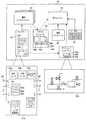
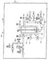
ここで図1を参照すると、スマートプロセスオブジェクトがプロセスグラフィックディスプレイおよびプロセスモジュールを形成するために使用され、その両方ともがプラント環境の中で強化された制御とシミュレーションを提供するために制御モジュールと統合されてよい例のプロセスプラント10が詳細に描かれている。特に、プロセスプラント10は、各々が、例えばFieldbusインタフェース、Profibusインタフェース、HARTインタフェース、標準4−20maインタフェース等であってよい入力/出力(I/O)デバイスまたはカード18を介して1台以上のフィールドデバイス14と16に接続されている1台以上のコントローラ12を有する分散プロセス制御システムを使用している。コントローラ12は、例えばイーサネット(登録商標)リンクであってよいデータハイウェイ24を介して、1つ以上のホストワークステーションまたはオペレータワークステーション20と22に結合されている。データベース28は、データハイウェイ24に接続されてよく、パラメータ、ステータスおよびプラント10内のコントローラおよびフィールドデバイスと関連付けられている他のデータを収集し、記憶するデータヒストリアンとして、および/またはコントローラ12およびフィールドデバイス14と16にダウンロードされる、およびそれらの中に記憶されるようなプラント10内のプロセス制御システムの現在の構成を記憶する構成データベースとして動作する。コントローラ12、I/Oカード18およびフィールドデバイス14と16は通常、ときには厳しい工場環境の中で下方に配置され、それ全体で分散されているが、オペレータワークステーション20と22、およびデータベース28はコントロールルームあるいはコントローラまたは保守人員が容易に評価できる他のあまり厳しくない環境に配置されている。 Referring now to FIG. 1, smart process objects are used to form process graphic displays and process modules, both of which integrate with the control module to provide enhanced control and simulation within the plant environment. An
公知のように、一例としてエマーソンプロセスマネジメント(Emerson Process Management)によって販売されているDeltaV(登録商標)であってよいコントローラ12の各々は、任意の数の異なる、個別に実行される制御モジュールまたはブロック29を使用して制御戦略を実現するコントローラアプリケーションを記憶し、実行する。制御モジュール29は、機能ブロックと一般的に呼ばれているものから構成することができ、各機能ブロックは全体的な制御ルーチンの一部つまりサブルーチンであり、プロセスプラント10の中でプロセス制御ループを実現するために(リンクと呼ばれている通信を介して)他の機能ブロックと連動して動作する。周知のように、オブジェクト指向プログラミングプロトコル内でオブジェクトであってよい機能ブロックは、通常、送信機、センサ、または他のプロセスパラメータ測定装置と関連付けられているもの等の入力機能、PID、ファジー論理当制御を実行する制御ルーチンと関連付けられているもの等の制御機能、またはプロセスプラント10内でいくつかの物理的な機能を実行するためにバルブ等の何らかのデバイスの動作を制御する出力機能の内の1つを実行する。言うまでもなく、モデル予測コントローラ(MPC)、オプティマイザ等のハイブリッドタイプおよび他のタイプの複雑な機能ブロックが存在する。FieldbusプロトコルおよびDeltaVシステムプロトコルは、オブジェクト指向プログラミングプロトコルで設計され、実現される制御モジュールと機能ブロックを使用する一方で、制御モジュールは例えば順次機能ブロック、ラダー論理回路等を含む任意の所望の制御プログラミング方式を使用して設計することができ、機能ブロックまたは任意の他の特定のプログラミング技法を使用して設計され、実現されることに制限されていない。 As is known, each of the
図1に描かれているプラント10では、コントローラ12に接続されているフィールドデバイス14と16は標準4−20maデバイスであってよく、プロセッサとメモリを含む、あるいは他の任意の所望のタイプのデバイスであってよい、HART、Profitbus、またはFOUNDATION(登録商標)Fieldbusフィールドデバイス等のスマートフィールドデバイスであってよい。(図1で参照番号16を付与されている)Fieldbusフィールドデバイス等のこれらのデバイスのいくつかは、コントローラ12内で実現される制御戦略と関連付けられる、機能ブロック等のモジュールまたはサブモジュールを記憶し、実行してよい。図1にFieldbusデバイス16の2台の異なるデバイスの中に配置されるものとして図1に描かれている機能ブロック30は、周知のようにプロセス制御を実現するためにコントローラ12の中で制御モジュール29の実行と関連して実行されてよい。言うまでもなく、フィールドデバイス14と16はセンサ、バルブ、送信機、ポジショナ等の任意のタイプのデバイスであってよく、I/Oデバイス18はHART、Fieldbus、Profitbus等の任意の所望の通信プロトコルまたはコントローラプロトコルに準拠する任意のタイプのI/Oデバイスであってよい。 In the
図1のプロセスプラント10では、ワークステーション20は、プロセスプラント10の中で接続されているデバイス、装置等に関して機能性を見て、提供するために(他のタイプのユーザもユーザタイプについてカスタマイズされたディスプレイ層と関連して本書に後述されるように存在してよいが、本書では構成エンジニアおよびオペレータと呼ばれることもある)任意の許可されたユーザがアクセスできるオペレータインタフェースアプリケーションおよび他のデータ構造32一式を含む。該オペレータインタフェースアプリケーション32一式は、ワークステーション20のメモリ34に記憶され、アプリケーション一式32の中のアプリケーションまたはエンティティの各々はワークステーション20と関連してプロセッサ36で実行されるように適応される。アプリケーション32一式全体がワークステーション20に記憶されているものとして描かれているが、これらのアプリケーションまたは他のエンティティのいくつかはプラント10の中の、またはプラント10と関連付けられた他のワークステーションまたはコンピュータデバイスに記憶され、実行されることになる。さらに、アプリケーション一式はワークステーション20と関連付けられているディスプレイ画面37に、または携帯端末、ラップトップコンピュータ、他のワークステーション、プリンタ等を含む他の所望のディスプレイ画面またはディスプレイ装置にディスプレイ出力を出力できる。同様に、アプリケーション32一式の中のアプリケーションは分割され、2台以上のコンピュータまたは機械上で実行されてよく、相互に連動して動作するように構成されてよい。 In the
一般的に、アプリケーション32一式によって、3つの異なるタイプのエンティティの作成と使用が可能になり、その動作は、強化された制御機能、シミュレーション機能およびディスプレイ機能をプロセスプラント10のなかで提供するためにともに統合されてよい。より詳細には、アプリケーション32一式は(一般的にはプロセスプラントの一部に関するオペレータディスプレイを提供する)プロセスグラフィックディスプレイ35、(一般的にはプロセスプラントの一部のシミュレーションを提供する)プロセスモジュール39、および一般的にはプロセスのオンライン制御を提供または実行するプロセス制御モジュールを作成し、実現するために使用されてよい。プロセス制御モジュール29は該して技術で周知であり、機能ブロック制御モジュール等の任意のタイプの制御モジュールを含んでよい。より詳細に後述されるプロセスグラフィックディスプレイ要素35は、オペレータ等のユーザに、プロセスプラントおよびその中の要素の動作、構成またはセットアップについての情報を提供するために、一般的にはオペレータ、エンジニアまたは他のディスプレイによって使用される要素である。プロセスモジュール39は、通常プロセスグラフィックディスプレイ要素35に密接に結び付けられ、プロセスプラントの、あるいはプロセスグラフィックディスプレイ35に描かれている方法で接続されているその中の異なる要素のいくつかの動作のシミュレーションを実行するために使用されてよい。プロセスグラフィックディスプレイ35およびプロセスモジュール39は、ラップトップ型コンピュータ、携帯端末等を含む、プロセスプラント10に関連付けられている任意の他のコンピュータにダウンロードされ、その中で実行可能となるが、プロセスグラフィックディスプレイ35およびプロセスモジュール39は、ワークステーション20と22に記憶され、それらによって実行されるものとして描かれている。 In general, the set of
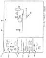
図2は、ワークステーション20のアプリケーション32一式の中のアプリケーションとデータ構造または他のエンティティのいくつかを描いている。特に、アプリケーション32一式は制御モジュール、プロセスモジュールおよび制御モジュール、(プロセスフローモジュールとも呼ばれる)プロセスモジュール、および関連グラフィックディスプレイを作成するために構成エンジニアによって使用されるグラフィックディスプレイ構成アプリケーション38を含む。制御モジュール構成アプリケーション38は任意の標準的な、または公知の制御モジュール構成アプリケーションであってよいが、プロセスモジュールおよびグラフィックディスプレイ構成アプリケーション(複数の場合がある)は1つ以上のスマートプロセスオブジェクトを使用してプロセスモジュールおよびグラフィックディスプレイを使用してよく、その性質はより詳細に後述することにする。またさらに、プロセスモジュールおよびプロセスグラフィック構成アプリケーション38は個別に示される一方、1つの構成アプリケーションはこれらのタイプの要素の両方ともを作成可能となる。 FIG. 2 depicts some of the applications and data structures or other entities in the set of
スマートプロセスオブジェクト42のライブラリ40は、プロセスモジュール39およびグラフィックディスプレイ35を作成するために構成アプリケーション38によってアクセスされ、コピーされ、使用さらえてよい例のまたはテンプレートのスマートプロセスオブジェクト42を含む。理解されるように、構成アプリケーション38は、1つ以上のプロセスモジュール39を作成するために使用されてよく、それら各々は1つ以上のスマートプロセスオブジェクト42から構成されるあるいは作成され、プロセスモジュールメモリ46に記憶されている1つ以上のプロセスフローまたはシミュレーションアルゴリズム45を含んでよい。さらに、構成アプリケーション38は、1つ以上のグラフィックディスプレイ35を作成するために使用されてよく、それら各々は1つ以上のスマートプロセスオブジェクト42から構成、あるいは作成され、ともに接続されている任意の数のディスプレイ要素を含んでよい。グラフィックディスプレイ35bの内の1つは拡大された形式で図2に描かれており、パイプ、導管、電力ケーブル、コンベヤ等であってよい接続要素によって相互接続されている、バルブ、タンク、センサおよびフロー送信機等のプロセス要素の集合の描写を含む。 The
実行エンジン48は、グラフィックディスプレイ35によって定義されるようにオペレータ向けの1つ以上のプロセスディスプレイを作成するために、およびプロセスモジュール39と関連付けられるシミュレーション機能性を実現するために実行時中にグラフィックディスプレイ35とプロセスモジュール39の各々を操作するまたは実現する。実行エンジン48は、全体をプロセスモジュール39で実現される論理、および特にそれらの論理の中でスマートプロセスオブジェクトを定義する記録データベース50を使用してよい。実行エンジン48は、プロセスモジュール39の機能性を実現するためにプロセスモジュール39の中のみではなく、プラント10の中でもプロセス要素間の接続を定義する接続マトリクス52も使用してよい。 The
図2は、より詳細には、スマートプロセスオブジェクト42eの内の1つを描いている。スマートプロセスオブジェクト42eはテンプレートスマートプロセスオブジェクトの内の1つであるとして描かれているが、他のスマートプロセスオブジェクトが概して、スマートプロセスオブジェクト42eに関して説明されているように、同じ、または類似する要素、特長、パラメータ等を含むこと、およびこれらの要素、特長およびパラメータの詳細または値がそのスマートプロセスオブジェクトの性質と用途に応じて、スマートプロセスオブジェクトごとに変更、または変えられてよいことが理解されるであろう。さらに、スマートプロセスオブジェクト42eはオブジェクト指向プログラミング環境の中のオブジェクトであってよく、したがってデータストア、入力と出力、およびそれと関連付けられるメソッドを含んでよい一方、このスマートプロセスオブジェクトは任意の他の所望のプログラミングパラダイムまたはプロトコルによって作成され、その中で実現されてよい。 FIG. 2 more particularly depicts one of the smart process objects 42e. Although the
理解されるように、インスタンスを作成される前のスマートプロセスオブジェクト42eは、図1のプロセスプラント10の中の物理エンティティまたは論理エンティティ等のある特定のタイプのエンティティと関連付けられているオブジェクトである。しかしながら、コピーされ、インスタンスを作成された後、スマートプロセスオブジェクト42eはプロセスプラントの中のある特定のエンティティに結び付けられてよい。いずれにせよ、スマートプロセスオブジェクト42eは、スマートプロセスオブジェクト42eが結び付けられている論理エンティティから受信される、または論理エンティティに関するデータを記憶するために使用されるスマートプロセスデータストア53を含む。データストア53は、製造メーカ、改訂、名称、種別等の、スマートプロセスオブジェクト42eが関連するエンティティについての一般的な情報または恒久的な情報を記憶するデータストア53aを含む。データストア53bは、パラメータデータ、ステータスデータ、入力データと出力データ、コスト、またはそれがプロセスプラント10の中に過去に存在したとき、または現在存在しているときの、エンティティと関連付けられるデータを含む、スマートプロセスオブジェクト42eが関連するエンティティについての他のデータ等の可変データまたは変化するデータを記憶してよい。言うまでもなく、スマートプロセスオブジェクト42eは、任意の所望の通信リンクを介してエンティティ自体から、イーサネット(登録商標)バス24を介してヒストリアン28から、または任意の他の所望の方法で、周期的に、または非周期的にこのデータ(例えばコストデータ)を受信するように構成、あるいはプログラミングされてよい。データストア53cは、スマートプロセスオブジェクト42eが関連し、図1のワークステーション20と関連付けられている画面37等の、オペレータインタフェースを介してオペレータへの実際のディスプレイのために使用されるエンティティのグラフィック表現を記憶してよい。言うまでもなく、グラフィック表現は、パラメータによって定義される情報、またはデータストア53bに記憶されるようなエンティティについての他の可変データ等のエンティティについての情報のプレースホルダ(データストア53c内で下線により記される)を含んでよい。このパラメータデータは、ディスプレイ装置37上でグラフィックディスプレイ35の内の1つの一部としてオペレータに提示されるとき、グラフィックプレースホルダに表示されてよい。グラフィック表現(およびスマートプロセスオブジェクト42e)は、オペレータまたは構成エンジニアが、グラフィック表現によって描かれているように、プロセス要素に上流または下流の構成要素を取り付けることができるようにする(データストア53cの中で「X」で記される)所定の接続点も含んでよい。言うまでもなく、これらの接続点により、スマートプロセスオブジェクト42eは、プロセスモジュール内で構成されるものとしてそのスマートオブジェクトに接続される要素を認識することも可能となり、パイプ、ダクト等、その要素等に関連付けられるストリーム等、使用されなければならないあるタイプの接続要素を指定してよい。 As will be appreciated, the
スマートプロセスオブジェクト42eは、スマートプロセスオブジェクト42が使用されるプロセスモジュールの内部または外部で他のスマートプロセスオブジェクトとの通信を可能にするために1つ以上の入力54および出力56も含んでよい。他のスマートプロセスオブジェクトへの入力54と出力56の接続は、他のスマートプロセスオブジェクトをこれらの入力と出力に単に接続することにより、あるいはスマートプロセスオブジェクト間で発生すべき特定の通信を指定することにより、プロセスモジュールの構成中に構成エンジニアによって構成されてよい。これらの入力と出力のいくつかは、前述されたようにスマートプロセスオブジェクトのための所定の接続ポイントで接続されるスマートプロセスオブジェクトに接続されているものとして定義されてよい。これらの入力54と出力56は、規則データベース50内の一式の規則およびプラント10の中の異なるデバイスまたはエンティティの間で接続を定義する接続マトリクス52によって決定または定義されてもよい。それらと関連付けられているデータストアまたはバッファを含む入力54と出力56は、一般的に、他のスマートプロセスオブジェクトからスマートプロセスオブジェクト42eにデータの通信を提供するために、あるいはスマートプロセスオブジェクト42の中に記憶される、またはスマートプロセスオブジェクト42eによって生成されるデータの通信を他のスマートプロセスオブジェクトに提供するために使用される。入力および出力は、スマートプロセスオブジェクト42eと、コントローラ12、フィールドデバイス14、16等の中の制御モジュール等のプロセス制御システム内の他のオブジェクトとの間で通信を提供するために使用されてもよい。 The
図2に描かれているように、スマートプロセスオブジェクト42eは、スマートプロセスオブジェクト42eが使用されるプロセスモジュールの実行中にスマートプロセスオブジェクト42eによって実現されるアルゴリズムであってよい(図2でメソッド60a、60b、および60cとして描かれている)0個、1個またはそれ以上のメソッド60を記憶するために使用されるメソッド記憶装置58も含む。一般的に、メソッド記憶装置58に記憶されているメソッド60は、プロセスプラント10またはプラント10内のエンティティについての情報を判定するために、データ記憶部分53aと53bの中に記憶されているデータ、および他のスマートプロセスオブジェクトから取得されるデータ、または入力54と出力56を介して構成データベースまたはヒストリアン28のような他のソースからのデータも使用する。例えば、メソッド60はスマートプロセスオブジェクト42eによって定義されるエンティティと関連付けられる質が悪いまたは不良の動作状態、プロセスプラント10の中のそのまたは他のエンティティと関連付けられるエラー等を決定してよい。メソッド60は、スマートプロセスオブジェクトのタイプまたはクラスに基づいて事前に設定または提供されてよく、毎回スマートプロセスオブジェクト42eが実行時中に実行エンジン48の中で実行されるたびに実行されることになる。スマートプロセスオブジェクト42e等のスマートプロセスオブジェクトの中で提供されてよいいくつかの例のメソッド60は漏れ、デッドバンド、不動作時間、移動、可変、状態監視、計算費用、またはエンティティと関連付けられる他の状態を検出することを含む。 As depicted in FIG. 2,
メソッド60は、そのプロセスエンティティを通って流れる材料に関してスマートプロセスオブジェクトと関連付けられるプロセスエンティティの動作をシミュレーションするのに役立つようにするためにも提供されてよい。このようにして、メソッド60は、要素の動作をシミュレーションし、提供されている入力に基づいて予想出力を計算するために、質量平衡、エネルギーバランス、流量、温度、組成、蒸気状態、およびプラント10の中で材料と関連付けられる他のシステムレベルまたはストリームレベルのパラメータを計算するために提供されてよい。言うまでもなく、これらはスマートプロセスオブジェクト42eに記憶し、それによって実行できるメソッドの内の数個に過ぎず、使用されてよい他の多くのメソッドがあり、このようなメソッドは、通常表現されているエンティティのタイプ、他の要因のみではなく、そのエンティティがプロセスプラント内でどのように接続され、使用されるのかによっても決定されている。スマートプロセスオブジェクト42eがシステムレベルの状態、エラー等を検出するメソッドを記憶し、実行してよい一方、これらのメソッドはプロセス制御モジュールとループ等のデバイス、論理要素、および他の非システムレベルエンティティについての他の情報を決定するために使用されてもよいことに留意することが重要である。所望の場合、メソッド60は、C、C++、C#等の任意の所望のプログラミング言語でプログラミング、または提供されてよいか、あるいは実行中にスマートプロセスオブジェクト42eのために実行されなければならない規則データベース50の中で適用可能な規則に参照され、あるいは適用可能な規則を定義してよい。 A
所望の場合、各スマートプロセスオブジェクトは、プロセスモジュール内で接続される場合にスマートプロセスオブジェクトのシミュレーション動作を定義するために使用されてよい適用可能なアルゴリズムまたはメソッドのライブラリを含んでよい。このようなライブラリは図2のスマートプロセスオブジェクト42eのためのプルダウンメニュー61に描かれており、類似するメニューは各々の他のスマートプロセスオブジェクトと関連付けられてよい。構成エンジニアは、このスマートプロセスオブジェクトが、例えばプルダウンメニュー61を介して(メソッド1、メソッド2等と呼ばれている)シミュレーションアルゴリズムのライブラリの内の1つを選択することによりプロセスモジュール39に格納される場合にスマートプロセスオブジェクトのシミュレーション動作を定義してよい。このようにして、構成エンジニアは、スマートプロセスオブジェクトがモデル化するために使用されているプロセスのタイプまたは性質に依存しているスマートプロセスオブジェクトのために異なるシミュレーション動作を定義してよい。 If desired, each smart process object may include a library of applicable algorithms or methods that may be used to define the simulation behavior of the smart process object when connected within a process module. Such a library is depicted in the pull-down menu 61 for the
所望の場合、構成エンジニアは、代わりにスマートプロセスブロックによって定義されるプロセス要素のシミュレーション動作を定義するために、独自仕様の、または他のユーザによって供給されるアルゴリズムを提供してよい。(プルダウンメニュー61で「ユーザによって定義された」エントリとして描かれている)このようなユーザによって定義されたアルゴリズムは、そのスマートプロセスオブジェクトがプロセスモジュール39の中に置かれる、あるいはプロセスモジュール39の中で使用される場合にスマートプロセスオブジェクトに提供され、その中に記憶されてよい。該機能性により、シミュレーション動作はユーザがカスタマイズし、それにより、より優れた、またはより正確なシミュレーションを提供できるようになる。所望の場合、およびより詳しく後述されるように、スマートプロセスオブジェクト42または各プロセスモジュール39は、スマートプロセスオブジェクト内のシミュレーションアルゴリズムの使用を無効にし、代わりにプロセスモジュールの動作を、HYSYSによって提供されるもの等の高品位シミュレーションパッケージまたはプログラムによって決定させる(電子スイッチまたはフラグ等の)オペレータが作動可能なスイッチを含んでよい。このケースでは、スマートプロセスオブジェクトまたはプロセスモジュールは、スマートプロセスオブジェクト自体の中でシミュレーションアルゴリズムを使用することと対照的に高品位シミュレーションからシミュレーションされたパラメータデータを取得する。 If desired, the configuration engineer may instead provide a proprietary or other user supplied algorithm to define the simulation behavior of the process elements defined by the smart process block. Such a user-defined algorithm (drawn as a “user-defined” entry in the pull-down menu 61) is such that the smart process object is placed in the
グラフィックディスプレイ35またはプロセスモジュール39の実行エンジン48による実行中、エンジン48は、グラフィックディスプレイ35またはプロセスモジュール39内のスマートプロセスオブジェクトの各々に入力54と出力56によって定義される通信を実現し、メソッド60によって提供される機能性を実行するために、それらのオブジェクトの各々にメソッド60を実現してよい。前記に注記されたように、メソッド60の機能性はスマートプロセスオブジェクトの中のプログラミングに位置してよいか、あるいはそれらの規則によって定義される機能性を実現するために、スマートプロセスオブジェクトのタイプ、クラス、識別、タグ名等に基づいて、エンジン48が実行する規則データベース50内の一式の規則によって定義されてよい。 During execution by the
スマートプロセスオブジェクト42eのインスタンスが、スマートプロセスオブジェクト42eが関連付けられるプロセスモジュールの関連でタグまたは一意の名前を有しており、このタグまたは一意の名前がスマートプロセスオブジェクト42eへ、およびスマートプロセスオブジェクト42eから通信を提供するために使用されてよく、実行時中に実行エンジン48によって参照されてよいことが注記される。プロセスモジュールタグは制御システム構成の中で一意でなければならない。このタグ付け規約により、プロセスモジュール39の中の要素は、プロセスグラフィックディスプレイ35、プロセスモジュール39、および制御モジュール29の他の中の要素によっても参照できる。またさらに、スマートプロセスオブジェクト42のパラメータは単純な値のような単純なパラメータ、構造化されたパラメータ、または予想される装置とそれと関連付けられている属性を知っているスマートパラメータである場合がある。スマートパラメータは、すべての信号が同じ装置内で送信されている、あるいは適切に変換されていることを保証するために、プロセス規則エンジンまたは実行エンジン48によって解釈、使用できる。スマート規則は、オペレータ向けのスマートアラーム戦略および/またはインタフェースを作成するためにスマートプロセスオブジェクト(またはプロセスモジュール)のためのアラームのグループをオンにし、オフにするために使用することもできる。またさらに、スマートプロセスオブジェクトクラスは、スマートプロセスオブジェクトと、それが解釈またはアクセスする必要のあるプロセス変数のと間の公知のリンケージを提供するために、プラント10のプロセス制御戦略の中で装置とモジュールクラスと関連付けることができる。 An instance of the
スマートプロセスオブジェクトは、プロセスグラフィックディスプレイまたはプロセスモジュールの中で使用されるとき、これらのスマートオブジェクトがオフモード、起動モード、および通常モード等の実行時中の異なるモードにされてよいように動作モード、ステータス、アラーム動作も含んでよく、その現在の動作状態に基づいてオブジェクトと関連付けられるステータスを提供してよく、パラメータ範囲外、限定、高可変性等の検出された状態に基づいてアラームを提供してよい。スマートプロセスオブジェクトは、それらをクラスライブラリで分類する、複合構造でともに収集する等を行うことができるようにするクラス/サブクラス階層も有してよい。さらに、スマートプロセスオブジェクトは、スマートプロセスオブジェクトが、その関連エンティティがいずれの時点でビジーなのか、あるいは例えばプラント10内でバッチ制御プロセスによって取得されるときを認識できるようにするために、制御モジュールおよび他のオブジェクト等の他の要素からの情報を活用してよい。 When smart process objects are used in a process graphic display or process module, these smart objects may be put into different modes at runtime, such as off mode, startup mode, and normal mode, Status, alarm actions may also be included, status associated with the object may be provided based on its current operational state, and alarms may be provided based on detected conditions such as out of parameter range, limited, high variability, etc. It's okay. Smart process objects may also have a class / subclass hierarchy that allows them to be classified in a class library, collected together in a composite structure, and so on. In addition, the smart process object has a control module and a smart module so that the smart process object can recognize when its associated entity is busy or when it is acquired by, for example, a batch control process in the
スマートプロセスオブジェクトは、ポンプ、タンク、バルブ等の物理デバイス、あるいはプロセス領域、測定、またはアクチュエータ、制御戦略等の論理エンティティ等の任意の所望のプロセスエンティティと関連付けられてよい。いくつかのケースでは、スマートプロセスオブジェクトは、コネクタ、このような配管、導管、配線、コンベヤ、あるいは材料、電気、ガス等をプロセスの中のある点から別の点へ移動する任意の他のデバイスまたはエンティティと関連付けられてよい。本書ではスマートリンクまたはコネクタ要素と呼ばれることもあるコネクタと関連付けられているスマートプロセスオブジェクトには(たとえ実際のデバイスまたはコネクタ自体にタグが付けられていない、あるいはプロセスプラント10内で通信可能にきないとしても)タグも付けられ、一般的に、プロセスの中の他の要素間の材料の流れを表すために使用される。 A smart process object may be associated with any desired process entity, such as a physical device such as a pump, tank, valve, or logical entity such as a process area, measurement, or actuator, control strategy. In some cases, smart process objects are connectors, such pipes, conduits, wires, conveyors, or any other device that moves material, electricity, gas, etc. from one point in the process to another. Or it may be associated with an entity. Smart process objects associated with connectors, sometimes referred to as smart links or connector elements in this document (even if the actual device or connector itself is not tagged or cannot communicate within the process plant 10) Tag) and is typically used to represent the flow of material between other elements in the process.
スマートリンクは、異なる材料または(電気等の)現象がいかにして接続(例えば、蒸気、電気、水、汚水等)を通って流れるのかを定義する特性またはパラメータを含む。これらのパラメータは、コネクタを通る流れ(全般的な速度、摩擦係数、乱流または非乱流、電磁のような流れのタイプ等)のタイプと性質およびコネクタを通る流れの考えられる1つ以上の方向を示してよい。スマートリンクは、ソースおよびスマートリンクが接続する宛先オブジェクトの単位が一致することを保証するプログラミングまたはメソッドを含んでよく、一致しない場合には変換を実行してよい。スマートリンクのメソッドは、実際のコネクタを通る流れの速度または性質、物理的な接続の長さとサイズ、トランスポート遅延等を推定するためにモデルまたはアルゴリズムを使用してコネクタを通る流れをモデル化してもよい。(摩擦パラメータ等の)スマートプロセスオブジェクトのために記憶されているパラメータはこれらのメソッドで使用されてよい。したがって、本質的には、スマートリンクまたはコネクタ要素は、スマートプロセスオブジェクトが他の上流オブジェクトと下流オブジェクトまたはエンティティを認識できるようにする。スマートリンクが、例えば他のオブジェクトの間の接続、システム内の液体、ガス、電気等の流体のタイプ、他のエンティティがこのスマートプロセスオブジェクトのエンティティの上流および下流にあるエンティティの上流側と下流側、任意の所望の、または便宜的な材料、流体、電流等の方向を定義してよいことは言うまでもない。一実施形態では、プロセスフローモジュールの実行の前に行列52が作成されてよく、プラント内の異なるデバイス間の相互接続をスマートリンクのために、したがって異なるスマートプロセスオブジェクト間の相互接続を定義してよい。つまり、実行エンジン48は上流エンティティと下流エンティティを確定し、それによりスマートプロセスオブジェクトとスマートプロセスオブジェクトと関連付けられるメソッドの間の通信を定義するために行列52を使用してよい。またさらに、一式または複数式の規則が、スマートプロセスオブジェクト内のメソッドについて必要に応じて相互に反応するため、および必要に応じて相互にデータを取得するためにスマートプロセスオブジェクトによって使用されるために、ならびに出力接続と関連付けられるスマートオブジェクトの影響を解消するために提供されてよい。 Smart links include characteristics or parameters that define how different materials or phenomena (such as electricity) flow through connections (eg, steam, electricity, water, sewage, etc.). These parameters depend on the type and nature of the flow through the connector (general velocity, coefficient of friction, turbulent or non-turbulent, electromagnetic flow type, etc.) and one or more possible flows of the connector. Direction may be indicated. The smart link may include programming or methods that ensure that the source and destination object units to which the smart link connects match, and if not, perform a transformation. The smart link method models the flow through the connector using a model or algorithm to estimate the speed or nature of the flow through the actual connector, physical connection length and size, transport delay, etc. Also good. Parameters stored for smart process objects (such as friction parameters) may be used in these methods. Thus, in essence, a smart link or connector element enables a smart process object to recognize other upstream objects and downstream objects or entities. Smart links, for example, connections between other objects, types of fluids in the system, such as liquid, gas, electricity, etc., upstream and downstream of entities where other entities are upstream and downstream of this smart process object entity Of course, any desired or expedient material, fluid, current, etc. direction may be defined. In one embodiment, the
所望の場合、スマートプロセスオブジェクト42eは、オブジェクトのタイプに適用可能であってよく、あるいはスマートプロセスオブジェクト42eが関連するデバイスの(臨界および用途に応じて)インスタンスに特化したものであってよい重要な文書に対するURL等のホットリンクも含んでよい。該文書はユーザに特定であってよいのみではなくベンダによって供給されてもよい。文書のいくつかの例は、構成、起動、および停止の手順、操作と保守の文書を含む。所望の場合、オペレータはオブジェクトまたは関連デバイスのためにインスタンスに特化した(存在する場合)および総称的な文書を立ち上げるためにオペレータディスプレイに表示されるようにオブジェクトをクリックしてよい。また、オペレータは、保守要求、操作上の問題の記録等の、システムソフトウェアに関係なく文書を追加/削除/変更できることがある。さらに、これらのホットリンクは、オペレータインタフェースの中のオブジェクトに知識リンクを追加する能力を提供するため、オブジェクトに関連する適切な情報へのクイックナビゲーションに備えるため、および顧客に特化したオブジェクトタイプに、またはオブジェクトの特定のインスタンスにも特化した作業指示書を追加する能力を提供するために、ユーザによって設定可能または変更可能であってよい。 If desired, the
プロセスモジュールおよびプロセスグラフィックスは異なるスマートプロセスオブジェクトの相互接続によりともに作成されるものとして前述されているが、それらは個別に作成されてよい。例えば、プロセスグラフィックはスマートプロセスオブジェクトを使用して作成されてよく、完了時、そのグラフィックのためのプロセスモジュールはグラフィックディスプレイの中のグラフィック要素およびそれらの相互接続に基づいて生成されてよい。代わりに、プロセスモジュールはスマートプロセスオブジェクトを使用して最初に作成されてよく、いったん作成されると、そのプロセスモジュールのためのグラフィックディスプレイはプロセスモジュールを作成するために使用されるスマートプロセスオブジェクト内のグラフィックディスプレイ要素を使用して構成アプリケーション38によって自動的に生成されてよい。またさらに、プロセスモジュールとグラフィックディスプレイは個別に作成されてよく、これら2つのエンティティの中の個々の要素は互いを参照する(例えば、グラフィックディスプレイとプロセスモジュールの中の要素のタグ特性を使用する)ことにより手動でともに結び付けられてよい。この機構を通じて、スマートプロセスオブジェクトは複数のディスプレイによって参照されてよい。いずれにせよ、いったん作成されると、プロセスグラフィックディスプレイおよび関連付けられるプロセスモジュールは、それらは所望のようにまたは必要に応じてパラメータと情報を前後に通信するが、無関係にまたは個別に実行されてよい。 Although process modules and process graphics are described above as being created together by the interconnection of different smart process objects, they may be created separately. For example, a process graphic may be created using a smart process object, and upon completion, a process module for that graphic may be generated based on the graphic elements in the graphic display and their interconnections. Instead, a process module may be initially created using a smart process object, and once created, the graphic display for that process module is in the smart process object used to create the process module. It may be automatically generated by the
一般的に、所定のグラフィック要素のセットは、ユーザが、プロセスプラントを反映するプロセスグラフィックディスプレイを構築が可能となるように構成アプリケーションで設けられてよい。これらのディスプレイは、制御システムと対話し、その結果としてオンライン動作に関与するオペレータまたは他の人員によって通常監視され、活用される情報を提示してよいオンライン測定とアクチュエータを動的に示すように設計されるグラフィックディスプレイ要素を有する。加えて、プロセス動作を反映する測定されていないパラメータは、プロセスモジュールに提供されるオンラインプロセスシミュレーションを使用して計算されてよく、関連するグラフィックディスプレイの一体化した部分として示されてよい。このようにして、および他のやり方で、プロセスグラフィックディスプレイはエンジニアリング人員または経営管理者等のオペレータ以外のプラント人員によって通常監視、および活用される情報を提供してよい。 In general, a predetermined set of graphic elements may be provided in a configuration application to allow a user to build a process graphic display that reflects the process plant. These displays are designed to dynamically show on-line measurements and actuators that interact with the control system and as a result may present information that is normally monitored and utilized by operators or other personnel involved in the on-line operation. Graphic display elements. In addition, unmeasured parameters that reflect process behavior may be calculated using an on-line process simulation provided to the process module and may be shown as an integral part of the associated graphic display. In this manner and in other ways, the process graphic display may provide information that is normally monitored and utilized by plant personnel other than operators such as engineering personnel or managers.
さらに、エンジニアリングまたはトレーニングシミュレーションの目的に使用されてよいオフライン環境では、プロセスモジュールによって提供されるプロセスシミュレーション値は、それ以外の場合、グラフィック要素および関連する制御モジュールによって提供される実際のプロセス測定値の代わりに使用されてよい、および/または表示されてよい。関連プロセスモジュールまたはサードパーティシミュレーションアプリケーション(例えばHYSYS)によって計算されてよいこれらのシミュレーション値は、外乱設定値またはプロセスグラフィックディスプレイおよびそれらの各々のグラフィックディスプレイ要素を介して確立され、プロセスグラフィックディスプレイおよびそれらの各々のグラフィックディスプレイ要素に描写されてよいユーザによって指定される値のみではなく、(アクチュエータの一または状態等の)実際のプラント設定値に基づいてよい。これらの目的において、プロセスグラフィックディスプレイのオフラインビューのためにカスタマイズされたプロセスグラフィックディスプレイのコンテンツ層は、生成され、例えばトレーニングコンテキストで使用可能にされてよい。プロセスグラフィックディスプレイのこのコンテンツ層に関する詳細は後述される。 In addition, in an offline environment that may be used for engineering or training simulation purposes, the process simulation values provided by the process module are otherwise the actual process measurements provided by the graphic elements and associated control modules. Instead, it may be used and / or displayed. These simulation values, which may be calculated by an associated process module or a third party simulation application (eg HYSYS), are established via disturbance settings or process graphic displays and their respective graphic display elements, and process graphic displays and their It may be based on actual plant settings (such as one or status of the actuator) as well as values specified by the user that may be depicted on each graphic display element. For these purposes, a process graphics display content layer customized for an offline view of the process graphics display may be generated and made available, for example, in a training context. Details regarding this content layer of the process graphic display will be described later.
より一般的には、プロセスグラフィックディスプレイは、オンライン状況つまり制御状況と、オフラインつまりシミュレーション状況の両方を必要とする種々の状況で、多くの異なるタイプの人員によって使用されてよい。この目的のため、各プロセスグラフィックディsプレイはこれらの異なる文脈、状況および人員に専用の複数のコンテンツ層を有してよい。個別の独立したディスプレイを有する過去のシステムとは異なり、これらの専用コンテンツ層は、同じ1つ以上のオブジェクトが異なるコンテンツ層のすべてを生成するために必要な情報をそれと関連付けるという意味で、それらを定義するために使用されるオブジェクトの統合された部分である。その結果、単一のプロセスグラフィックディスプレイのコンテンツ層は、ビューの各々に個別のディスプレイを作成することを構成エンジニアまたは他の設計人員に要求することなくカスタマイズされたビューを提供する。 More generally, process graphic displays may be used by many different types of personnel in a variety of situations that require both online or control situations and offline or simulation situations. For this purpose, each process graphic display may have multiple content layers dedicated to these different contexts, situations and personnel. Unlike past systems with separate independent displays, these dedicated content layers associate them with the information that the same one or more objects need to generate all of the different content layers. An integrated part of an object that is used to define. As a result, the content layer of a single process graphic display provides a customized view without requiring a configuration engineer or other design personnel to create a separate display for each of the views.
異なる機能(動作、エンジニアリング、保守、管理等)のためにカスタマイズされたユーザインタフェースディスプレイを生成するために必要とされる情報の大きさは、グラフィックディスプレイ要素およびそれに関連付けられるシミュレーションアルゴリズムの柔軟且つ拡張可能なセットによって提供され、サポートされる。ストリーム要素、プロセス接続要素、アクチュエータ要素、処理要素、測定要素および推定された特性要素を含む、多くの異なるタイプのプロセスプラント要素と対応してよいこれらのグラフィックディスプレイ要素は、プロセスグラフィックディスプレイおよびその幅広い機能性を作成する上で使用するために事前に定義、あるいはそれ以外の場合に利用可能にされてよい。カスタム要素は、特定のタイプの前記プロセスプラント要素、このような要素の合成物、および基本的なグラフィック形状(例えば、線、円等)から構成されるまったく新しい要素をカバーするために構成エンジニアによって作成または生成されてもよい。 The amount of information required to generate a customized user interface display for different functions (operation, engineering, maintenance, management, etc.) is flexible and extensible for graphic display elements and associated simulation algorithms Provided and supported by a complete set. These graphic display elements, which may correspond to many different types of process plant elements, including stream elements, process connection elements, actuator elements, processing elements, measurement elements and estimated characteristic elements, are process graphic displays and their wide range It may be predefined or otherwise made available for use in creating functionality. Custom elements are created by configuration engineers to cover a whole new element consisting of a specific type of said process plant element, a composite of such elements, and basic graphic shapes (eg lines, circles, etc.) It may be created or generated.
ストリーム要素は、概してプロセスプラントの中の材料のストリームを定義し、組成、密度、流量、温度、圧力、重量、および/または材料のストリームを定義する他のパラメータを示すためにグラフィックディスプレイに露呈されてよい。ストリーム要素はプロセスモジュールの入力時に定義され、プロセスモジュールの中の要素に提供され、それによりプロセスモジュールを通る材料の流れをグラフィックをモデル化し、グラフィックディスプレイで描写できるようにする。同様に、ストリーム要素は、グラフィックディスプレイによって描写されるプロセスプラントの部分の材料出力をグラフィックディスプレイの中に描くために、プロセスモジュールの出力時、つまり最後に描かれてよい。ストリーム要素は、異なるグラフィックディスプレイ(および関連付けられたプロセスモジュール)が相互にいかにして接続されるのかを定義するために使用されてもよい。例えば、1つのプロセスモジュールの出力ストリームは、別のプロセスモジュールでの入力ストリームであってよく、他のプロセスモジュールの入力ストリームで使用される値を供給してよい。ストリームは以下の4つのパーツ、つまり名前(例えばpHストリーム)、方向(例えば、流量入力)、測定(例えば、流量、圧力、温度)および組成(例えば、窒素、アンモニア等)を含んでよい。しかしながら、ストリームは、そのように所望の場合、他のパーツまたパラメータを有することになる。 Stream elements generally define a stream of material in a process plant and are exposed on a graphic display to indicate composition, density, flow rate, temperature, pressure, weight, and / or other parameters that define the material stream. You can. Stream elements are defined at the input of a process module and are provided to the elements in the process module so that the flow of material through the process module can be modeled and rendered on a graphic display. Similarly, the stream elements may be drawn at the output of the process module, ie at the end, to draw the material output of the portion of the process plant drawn by the graphic display into the graphic display. Stream elements may be used to define how different graphic displays (and associated process modules) are connected to each other. For example, an output stream of one process module may be an input stream in another process module and may provide values used in an input stream of another process module. The stream may include the following four parts: name (eg, pH stream), direction (eg, flow rate input), measurement (eg, flow rate, pressure, temperature) and composition (eg, nitrogen, ammonia, etc.). However, the stream will have other parts or parameters if so desired.
プロセス接続要素は、固形物、液体と蒸気、および気体等のプラントないの材料があるデバイスから別のデバイスへいかにして送達されるのか、または搬送されるのかを定義する。プロセスを通過する材料の流れを明確に描くために、配管、ダクト、およびコンベヤを含む3種類の異なるタイプのプロセス接続が使用されてよい。言うまでもなく、電解加工プロセス等における電力潮流に対処するために電気ケーブル等の他の接続要素も使用されてよい。配管は、通常、プラントの中の液体、および高圧蒸気または気体の流れを描く(そしてシミュレーションする)ために使用される。ダクトは、通常プラント内の低圧ガスの流れを描く(そしてシミュレーションする)ために使用される。コンベヤは、通常、処理装置間の固形物の移動を描く(そしてシミュレーションする)ために使用される。その結果として、各プロセス補正要素は、デバイスの入力または出力時に材料を提供するために使用される、パイプ接続、ダクト接続、またはコンベヤ接続等の接続のタイプを定義する。 Process connection elements define how plant-free materials such as solids, liquids and vapors, and gases are delivered or transported from one device to another. Three different types of process connections may be used to clearly depict the material flow through the process, including piping, ducts, and conveyors. Needless to say, other connection elements such as electrical cables may also be used to cope with power flow in an electrochemical machining process or the like. Piping is typically used to depict (and simulate) the flow of liquid and high-pressure steam or gas in the plant. Ducts are typically used to depict (and simulate) the flow of low pressure gas in a plant. A conveyor is typically used to depict (and simulate) the movement of solids between processing equipment. As a result, each process compensation element defines the type of connection, such as pipe connection, duct connection, or conveyor connection, that is used to provide material at the input or output of the device.
所望の場合、接続によって移送されている材料の特性は上流入力によって決定される。接続が完了するか否かを定義する接続ステータス変数を加えたこの情報は、グラフィックディスプレイ上での接続要素の特性として入手可能にされてよい。接続要素は処理要素出力、アクチュエータ要素出力、またはストリーム要素出力時に開始してよい。同様に、接続要素は処理要素入力、アクチュエータ要素出力、またはストリーム入力時に終了してよい。 If desired, the properties of the material being transferred by the connection are determined by the upstream input. This information plus a connection status variable defining whether the connection is complete may be made available as a characteristic of the connection element on the graphic display. The connection element may start on processing element output, actuator element output, or stream element output. Similarly, a connection element may terminate upon processing element input, actuator element output, or stream input.
接続要素の特性は、カーソルがグラフィックディスプレイの接続要素上に置かれた場合に自動的に表示されてよい。また、接続要素と関連する特性は、接続要素上に測定値または推定された特性要素(以下に定義されている)を置くことにより恒久的なディスプレイのために露呈されてよい。所望の場合、接続要素は、(ストリーム出力、処理要素出力、またはアクチュエータ要素出力等の)要素出力の上で左マウスボタンを押し下げ、マウスのボタンを押し下げている間に、要素入力上にカーソルを配置することで、さらに作成されてよい。接続が無事に確立されるためには、上流要素と下流要素の入力タイプと出力タイプ(パイプ、ダクトまたはコンベヤ)が一致しなければならない。接続は上流要素のタイプを自動的に獲得しなければならない。 The characteristics of the connection element may be automatically displayed when the cursor is placed on the connection element of the graphic display. Also, the characteristics associated with the connection element may be exposed for a permanent display by placing measured or estimated characteristic elements (defined below) on the connection element. If desired, the connection element depresses the left mouse button on an element output (such as a stream output, processing element output, or actuator element output) and places the cursor on the element input while depressing the mouse button. It may be further created by arranging. In order for the connection to be established successfully, the input type and output type (pipe, duct or conveyor) of the upstream and downstream elements must match. The connection must automatically acquire the type of upstream element.
所望の場合、配管要素は、パイプ接続としてプロセスグラフィックディスプレイに示される、または描写でき、ダクト要素(例えば空気またはガス)はダクトとして示すことができ、コンベヤ要素はコンベヤベルトとして示すことができる。配管、ダクトおよびコンベヤ要素接続は、プロセス要素間で自動的に経路設定することができ、矢印は流れの方向を示すためにこれらの要素の描写の外部に表示されてよい。上流出力が2つの接続に共通である場合には、「T」要素はパイプ、ダクトまたはコンベヤに含まれてよい。同様に、「T」個の要素は複数の出力を結合するために使用されてよい。コンベヤ要素の色または他のグラフィック特性は、そのステータス、例えば実行中/停止中、流れている/流れていない、差し込まれている等を示すために変化してよい。一般的に、コンベヤに沿った材料の流れは、コンベヤに接続されるモータドライブによって決定される。したがって、(詳しく後述されるアクチュエータ要素である)モータドライブアクチュエータがコンベヤに接続されてよい。さらに、測定要素(後述される)は、コンベヤの速度またはパイプまたはダクト内の材料の流量、水分または重量等のコンベヤ、パイプまたはダクトの上または中の材料の特性等のパイプ、ダクトまたはコンベヤ要素に関連する測定値を露呈できるようにするためにパイプ、ダクトおよびコンベヤ要素に接続できる。また、露呈される特性要素は、例えば材料の組成について測定されていないパイプ、ダクト、またはコンベヤの上または中の材料の特性を表示するために追加されてもよい。 If desired, the piping elements can be shown or depicted in the process graphic display as pipe connections, the duct elements (eg, air or gas) can be shown as ducts, and the conveyor elements can be shown as conveyor belts. Piping, duct and conveyor element connections can be automatically routed between process elements, and arrows may be displayed outside the depiction of these elements to indicate the direction of flow. If the upstream output is common to the two connections, a “T” element may be included in the pipe, duct or conveyor. Similarly, “T” elements may be used to combine multiple outputs. The color or other graphic characteristics of the conveyor element may change to indicate its status, eg running / stopped, flowing / not flowing, plugged, etc. In general, the flow of material along the conveyor is determined by a motor drive connected to the conveyor. Thus, a motor drive actuator (which is an actuator element described in detail below) may be connected to the conveyor. In addition, the measurement element (described below) is a pipe, duct or conveyor element such as conveyor speed or material flow rate in the pipe or duct, moisture or weight, etc., properties of the material on or in the pipe or duct Can be connected to pipes, ducts and conveyor elements to allow exposure of measurements related to Also, exposed characteristic elements may be added, for example, to indicate the properties of the material on or in the pipe, duct, or conveyor that have not been measured for the composition of the material.
所望の場合、配管、ダクトおよびコンベヤ接続要素の各々は、(例えば変色により)失われた接続、および選択された特性(圧力、温度、長さ等)が(例えば変色によって)設定範囲外となることをグラフィックで、且つ動的に反映してよい。さらに、関連するプロセスモジュールによって計算されるパラメータは、グラフィックで露呈されてよい。例えば、接続要素または接続要素によって移送されているストリームについてオペレータに情報を提供するために、接続ステータスが不良であるのか、良好であるのかに関係なく、上流接続によって提供される特性、接続要素の1つ以上の選択されたパラメータに対する制限等がグラフィックディスプレイで露呈されるとよい。 If desired, each of the piping, duct and conveyor connection elements is lost connection (eg due to discoloration) and the selected properties (pressure, temperature, length, etc.) are outside the set range (eg due to discoloration) This may be reflected graphically and dynamically. Furthermore, the parameters calculated by the associated process module may be exposed graphically. For example, to provide information to the operator about the connection element or the stream being transported by the connection element, the characteristics provided by the upstream connection, whether the connection status is bad or good, Limitations, etc. on one or more selected parameters may be exposed on the graphic display.
一般的に、アクチュエータ要素は、ストリームに関して何らかの作動機能を実行する要素であり、異なる接続要素間、または処理要素と接続要素の間に設置されてよい。アクチュエータ要素の例は、(アクチュエータ付きの)調整弁、(アクチュエータ付きの)開閉弁、(モータ付きの)ポンプ、(モータ付きの)強制通風ファン、(モータ付き)誘引通風ファン、(開閉弁付き)エダクタ、(ドライブ付き)ダンパ、(可変速度モータ付き)フィーダ、(コンベヤ要素に取り付けられてよい)コンベヤモータドライブ等を含む。 In general, an actuator element is an element that performs some actuation function on a stream and may be placed between different connection elements or between a processing element and a connection element. Examples of actuator elements are regulator valves (with actuators), on-off valves (with actuators), pumps (with motors), forced draft fans (with motors), induction draft fans (with motors), (with on-off valves) ) Eductors, dampers (with drives), feeders (with variable speed motors), conveyor motor drives (which may be attached to conveyor elements), etc.
バルブ要素のグラフィック描写は、(例えば動画により)暗示されているバルブ位置、(例えば変色による)バルブ故障、(例えば変色による)バルブ完全開放/閉鎖位置、そのバルブを制御している関連制御ブロックの(例えば、数値文字列または他の表示による)AO、DO、DC、設定点、PV、OUT、モード等を動的に反映してよい。(プロセスモジュールで使用される)バルブ要素と関連するシミュレーション要素は、吐き出し圧力、マスフロー、液体温度、液組成、入口圧力、および出口圧力等のバルブアクチュエータと関連するパラメータを計算するシミュレーションアルゴリズムを有してよい。これらのシミュレーションされた、または計算されたパラメータは、所望の場合、プロセスグラフィックで露呈されてよい。しかしながら、通常、ユーザまたは構成エンジニアはバルブタイプ(例えば、線形、早開き、等しい百分率、バルブサイジング等)と開から閉へのストローク時間のみではなくバルブと関連する制御モジュールの中のAOブロック、DOブロックまたはDCブロックに対する参照を設定しなければならない。バルブを通って流れる材料に対するバルブの作用をシミュレーションするために使用可能なシミュレーションアルゴリズムはバルブのタイプとサイジングの情報に依存してよい。 Graphical depiction of the valve element includes the implied valve position (eg, due to animation), valve failure (eg, due to discoloration), valve fully open / closed position (eg, due to discoloration), and the associated control block controlling that valve. AO, DO, DC, set point, PV, OUT, mode, etc. (eg, by numeric string or other display) may be dynamically reflected. The simulation elements associated with the valve elements (used in the process module) have a simulation algorithm that calculates parameters associated with the valve actuator such as discharge pressure, mass flow, liquid temperature, liquid composition, inlet pressure, and outlet pressure. You can. These simulated or calculated parameters may be exposed in the process graphic if desired. However, the user or configuration engineer typically does not only determine the valve type (eg, linear, fast open, equal percentage, valve sizing, etc.) and the stroke time from open to close, but also the AO block, DO in the control module associated with the valve. A reference to the block or DC block must be set. The simulation algorithm that can be used to simulate the action of the valve on the material flowing through the valve may depend on the valve type and sizing information.
ポンプ要素のグラフィック描写は、(例えば変色を使用して)モータステータスを、(例えば文字列を使用して)関連するDOまたはDC機能ブロックモードと設定点を、(可変速度ドライブが使用される場合には)モータ速度を、(可変速度ドライブが使用される場合)AO設定点、PV、OUTモードを、および他の所望のパラメータを動的に反映してよい。同様に、この要素のための(プロセスモジュールで使用される)プロセスシミュレーションは、吐き出し圧力、液組成、液体温度、およびマスフロー等のパラメータを決定または計算してよく、そのパラメータはグラフィックディスプレイで露呈されてよい。ユーザはポンプタイプに基づいてポンプ曲線を画定する必要がある場合がある。しかしながら、ユーザはモータ起動/停止と関連するDOまたはDCブロックに対する参照、(使用されている場合)可変速度ドライブのための関連するAO機能ブロックに対する参照、およびポンプの動作を該定義することのための(圧力対フローの)ポンプ曲線を設定してよい。 Graphic representation of the pump element shows motor status (e.g. using discoloration), associated DO or DC function block mode and set point (e.g. using string) (if variable speed drive is used) ) May dynamically reflect motor speed, (if variable speed drive is used) AO set point, PV, OUT mode, and other desired parameters. Similarly, the process simulation (used in the process module) for this element may determine or calculate parameters such as discharge pressure, liquid composition, liquid temperature, and mass flow, which are exposed on a graphic display. You can. The user may need to define a pump curve based on the pump type. However, the user may refer to the DO or DC block associated with motor start / stop, a reference to the associated AO function block for variable speed drive (if used), and to define pump operation. A (pressure vs. flow) pump curve may be set.
強制通風または誘引通風アクチュエータ要素のグラフィック描写は、モータステータス、DOまたはDC機能ブロックモードと設定点、(可変速度ドライブが使用される場合)モータ速度、(可変速度ドライブが使用される場合)AO設定点、PV、OUT,DOまたはDC機能ブロックモード、および他の所望のパラメータを動的に反映する描写を有してよく、その内のいずれかがグラフィックディスプレイに露呈されてよい。この要素のための(プロセスモジュールで使用される)プロセスシミュレーション要素は、吐き出し圧力、ガス組成、ガス温度、およびガスマスフロー等のパラメータを決定または計算してよく、そのパラメータはグラフィックディスプレイに露呈されてよい。ユーザは、モータ起動/停止のための関連するDCブロックに対する参照、(使用されている場合)可変速度ドライブのためのAOブロックに対する参照、およびファンのシミュレーションされる動作を定義するためのファン曲線(圧力対流量)を設定してよい。 Graphic representations of forced or induced draft actuator elements include motor status, DO or DC function block modes and set points, motor speed (if variable speed drive is used), AO setting (if variable speed drive is used) It may have a depiction that dynamically reflects the point, PV, OUT, DO or DC function block modes, and other desired parameters, any of which may be exposed to the graphic display. The process simulation element (used in the process module) for this element may determine or calculate parameters such as discharge pressure, gas composition, gas temperature, and gas mass flow, which are exposed to the graphic display. Good. The user can refer to the relevant DC block for motor start / stop, a reference to the AO block for variable speed drive (if used), and a fan curve to define the simulated behavior of the fan ( Pressure versus flow) may be set.
いくつかのケースでは、特定のタイプのアクチュエータは、パイプ、ダクトまたはコンベヤのような特定のタイプの接続とだけ使用されてよい。以下の表は、典型的なアクチュエータ要素のためのいくつかの例の接続制限を定義する。
処理要素は、何らかの方法でプラント内の材料またはストリームを処理するプラント装置を含む。一般的に、処理要素に対するすべての入力と処理要素からのすべての出力は接続要素を通して行われる。標準処理要素はタンク(縦型と横型)、加熱器、スタティックミキサ、リアクタ、ミキサ、エアヒータ、および何らかのタイプの単純な、または標準的な処理活動を実行する他の要素を含む。標準処理要素の場合、ユーザは、サイズ、体積等の物理要素特性とともに要素への入力と出力の数を指定してよい。これらの標準的な処理要素のシミュレーションアルゴリズムおよび静的表現は、それらがユーザによって修正できないが、構成時間に前述されたように選択可能となるように設定されてよい。言うまでもなく、所望の場合、(蒸留塔、蒸発器、分離器、ボイラ等の)他の典型的により複雑なプラント装置はカスタム処理要素として実現されてよい。このようなカスタム処理要素の静的表現、入出力数、およびシミュレーションアルゴリズムはユーザインタフェース要件を満たすために修正されてよい。カスタム処理要素はいったん定義されると、それは再利用される、あるいは他の処理要素の作成で開始点として使用されてよい合成物またはテンプレートとして保存されてよい。 The processing elements include plant equipment that processes the material or stream in the plant in some way. In general, all inputs to and outputs from processing elements are made through connection elements. Standard processing elements include tanks (vertical and horizontal), heaters, static mixers, reactors, mixers, air heaters, and other elements that perform some type of simple or standard processing activity. For standard processing elements, the user may specify the number of inputs and outputs to the element along with physical element properties such as size and volume. The simulation algorithms and static representations of these standard processing elements may be set so that they cannot be modified by the user, but can be selected as described above at configuration time. Of course, if desired, other typically more complex plant equipment (such as distillation columns, evaporators, separators, boilers, etc.) may be implemented as custom processing elements. The static representation of such custom processing elements, the number of inputs and outputs, and the simulation algorithm may be modified to meet user interface requirements. Once a custom processing element is defined, it may be saved as a composite or template that may be reused or used as a starting point in the creation of other processing elements.
タンク標準処理要素(縦型または横型のどちらか)はタンクへのパイプ接続に基づいて設定されてよく、タンク要素は(例えば動的動画を使用して)タンク内の水位、および(例えば変色を使用して)100%または空の水位を動的に反映してよい。タンクのためのプロセスモジュールシミュレーションはグラフィックディスプレイを介して、出口温度、出口組成、液体温度およびタンクのシミュレーションされる水位等のパラメータを計算し、露呈してよい。しかしながら、タンクをシステムに結び付けるために、ユーザまたは構成エンジニアは、入出力の接続数、タンクへの完全な接続、サイズ(例えば直径と高さ)等のタンク特性等を設定する必要がある場合がある。 The tank standard processing element (either vertical or horizontal) may be set based on the pipe connection to the tank, the tank element (for example using dynamic animation) and the water level in the tank, and (for example discoloration) 100% or empty water level may be dynamically reflected. Process module simulation for the tank may calculate and expose parameters such as outlet temperature, outlet composition, liquid temperature and simulated water level of the tank via a graphic display. However, in order to tie the tank to the system, the user or configuration engineer may need to set the tank characteristics such as the number of input / output connections, complete connections to the tank, size (eg diameter and height), etc. is there.
加熱器処理要素は、グラフィックディスプレイを介して、(変色を使用する)熱伝達率、出口製品温度、入口製品温度、(固定低下を仮定する)出口圧力等を動的に計算し、反映してよい。ユーザまたは構成エンジニアは、クリーンな状態での加熱器、加熱器表面積、および熱伝達率を設定する必要がある。 The heater processing element dynamically calculates and reflects heat transfer rate (using discoloration), outlet product temperature, inlet product temperature, outlet pressure (assuming fixed drop) etc. via graphic display Good. The user or configuration engineer needs to set the heater, heater surface area, and heat transfer rate in a clean state.
言うまでもなく、スタティックミキサ、リアクタ、ミキサ、エアヒータ、熱交換器等の他の処理要素はこれらのタイプのデバイスに調整される表示機能とシミュレーション機能を有してよい。蒸留塔、蒸発器、分離器、ボイラ等の非標準処理要素は、標準選択に含まれていない場合、容器と関連するシミュレーションがユーザによって定義されてよいカスタム処理要素を使用してグラフィックで表現されてよい。これらの要素における処理は、各々の入力を容器の各々の出力と関連付けるステップ応答モデルとして記述または定義されてよい。入力は、ガスおよび/または液体ストリームであってよい。任意選択的に、ユーザは処理要素の入力と出力間の関係性を記述する方程式を定義してよく、これらの方程式はシミュレーションを実行するための要素を使用してプロセスモジュールに記憶されてよい。ユーザがカスタム処理要素に関連付けられる静的グラフィックを迅速に作成するのに役立たせる場合に所望の場合、いくつかの静的グラフ表現が提供されてよい。これらの単純なグラフィックが使用される場合、ユーザは所望の入出力の接続数と、カスタム処理要素によってサポートされている接続のタイプ(例えば、パイプ、ダクト、またはコンベヤ)を指定しさえすればよい。それに応じて、グラフィックアイテムが表示され、即座にオペレータグラフィックの作成で使用できる。所望の場合、ユーザがステップ応答としてシミュレーションアルゴリズムを指定することを選ぶと、プロセス要素の各入力と出力と関連する利得およびあらゆる原動力が指定されてよい。ユーザがカスタムアルゴリズムを選択する場合は、ユーザがシミュレーションアルゴリズムを定義するために表現エディタが設けられてよい。選択される方法に基づいて、カスタム処理要素出力の特性は異なって計算されてよい。さらに、ユーザは個別のソフトウェアアセンブリで定義したアルゴリズムの内の1つ以上を参照してよい。 Needless to say, other processing elements such as static mixers, reactors, mixers, air heaters, heat exchangers, etc. may have display and simulation functions tailored to these types of devices. Non-standard processing elements such as distillation columns, evaporators, separators, boilers, etc., if not included in the standard selection, are graphically represented using custom processing elements where the simulation associated with the vessel may be defined by the user. It's okay. The processing in these elements may be described or defined as a step response model that associates each input with each output of the container. The input may be a gas and / or liquid stream. Optionally, the user may define equations that describe the relationship between the inputs and outputs of the processing elements, and these equations may be stored in the process module using the elements for performing the simulation. Several static graph representations may be provided if desired to help the user quickly create static graphics associated with custom processing elements. When these simple graphics are used, the user need only specify the desired number of input / output connections and the type of connection supported by the custom processing element (eg, pipe, duct, or conveyor). . In response, graphic items are displayed and can be used immediately in creating operator graphics. If desired, if the user chooses to specify a simulation algorithm as a step response, the gain associated with each input and output of the process element and any motive force may be specified. If the user selects a custom algorithm, an expression editor may be provided for the user to define a simulation algorithm. Based on the method selected, the characteristics of the custom processing element output may be calculated differently. In addition, the user may reference one or more of the algorithms defined in the individual software assembly.
加えて、複数の所定の合成物またはテンプレートがカスタム処理要素を作成するために提供されてよい。これらのテンプレートは、例えば、出口ガスO2、出口ガスCO、生成されたストリーム、ボイラドラム水位、およびボイラ通風を計算するカスタムアルゴリズムを有するボイラテンプレートを含んでよい。このようなテンプレートは単一の燃料入力に基づいてよい。しかしながら、テンプレートを修正することにより、複数の燃料でボイラをシミュレーションできる。他の所定のテンプレートは噴霧乾燥機カスタム処理要素と連動して使用されてよく、分離器の動作をモデル化するためにステップ応答モデルを含んでよい専用容器−サイクロン分離器テンプレートを含んでよい。同様に、列テンプレート、噴霧乾燥機、および蒸発器本体は、予想されるプロセス応答を定義するためにステップ応答モデルを活用してよい。蒸発器では、エネルギー入力および入力流れの濃度に基づいて、出力流れの濃度と蒸気開放が計算できる。複数の蒸発気要素は、多重効用蒸発器を作成するために熱交換器とエダクタ要素とともに接続されてよい。同様に、専用容器−スタックカスタムテンプレート処理要素はボイラ処理要素とともに使用されてよい。この場合、入口の特性は所望の場合、修正を行わずにスタックを通って、あるいはスタックの中で実行されるエミッション削減を反映するために、搬送されてよい。 In addition, a plurality of predetermined composites or templates may be provided for creating custom processing elements. These templates may include, for example, a boiler template with a custom algorithm that calculates outlet gas O2, outlet gas CO, generated stream, boiler drum water level, and boiler ventilation. Such a template may be based on a single fuel input. However, the boiler can be simulated with a plurality of fuels by modifying the template. Other predetermined templates may be used in conjunction with the spray dryer custom processing element and may include a dedicated container-cyclone separator template that may include a step response model to model the operation of the separator. Similarly, column templates, spray dryers, and evaporator bodies may utilize a step response model to define the expected process response. In the evaporator, the output stream concentration and vapor release can be calculated based on the energy input and the input stream concentration. Multiple evaporative elements may be connected with the heat exchanger and eductor elements to create a multi-effect evaporator. Similarly, dedicated container-stack custom template processing elements may be used with boiler processing elements. In this case, the inlet characteristics may be conveyed through the stack without modification if desired, to reflect emission reductions performed in the stack.
グラフィックディスプレイおよびプロセスモジュールを作成するために使用できる他のタイプの要素は測定要素と特性要素を含む。測定要素は、物理的な送信機に関連付けられる測定値にアクセスするためにグラフィックディスプレイの中で使用されてよい送信機要素と、スイッチ送信機要素を含む。一般的には送信機要素は不良ステータスまたは不確実なステータス、制御モジュールの中の関連AI機能ブロックのモード、実際の送信機(センサ)と関連付けられている測定値とユニット等、または実際の送信機と関連付けられている他のデータを動的に反映してよい。オフラインモード(シミュレーションモード)では、送信機要素は、APまたはPCIブロックと関連付けられている値よりむしろプロセスモジュールによって提供されるシミュレーション値にアクセスし、表示するために使用されてよく、またシミュレーションされた制御ルーチンで使用される想定値として制御モジュールの中の関連AIブロックに測定値を提供するために使用されてよい。送信機要素は接続要素に、または処理要素に追加することができ、このような送信機要素がディスプレイに追加されるとき、ユーザは通常、測定値を提供しているコントローラ方式の関連するAIブロック、PCIブロックまたはDIブロックを識別する必要がある。オンラインモードでは、測定値はこの測定要素の隣に示されてよい。オフラインモード(つまりシミュレーションモード)では、(対応するプロセスモジュールによって作成されるような)シミュレーションされた測定値が、自動的に表示されてよい。オンライン動作では、ユーザは、測定が失敗した場合には、制御とディスプレイをシミュレーションされた値に切り替えることを選ぶことができる。 Other types of elements that can be used to create graphic displays and process modules include measurement elements and characteristic elements. Measurement elements include a transmitter element that may be used in a graphic display to access measurements associated with a physical transmitter, and a switch transmitter element. In general, the transmitter element is in bad status or uncertain status, the mode of the associated AI function block in the control module, the measurement and unit associated with the actual transmitter (sensor), etc., or the actual transmission Other data associated with the machine may be dynamically reflected. In offline mode (simulation mode), the transmitter element may be used and simulated to access and display simulation values provided by the process module rather than the values associated with the AP or PCI block. It may be used to provide a measurement value to an associated AI block in the control module as an assumed value used in the control routine. A transmitter element can be added to the connection element or to the processing element, and when such a transmitter element is added to the display, the user typically has an associated AI block of the controller scheme providing the measurement value. The PCI block or DI block needs to be identified. In the online mode, the measured value may be shown next to this measuring element. In offline mode (ie, simulation mode), simulated measurements (such as created by the corresponding process module) may be automatically displayed. In online operation, the user can choose to switch the control and display to simulated values if the measurement fails.
スイッチ要素は、不良ステータスまたは不確実なステータス、関連するDI(例えばマニュアルまたはOS)のモード、およびスイッチの離散値(オン、オフ等)を動的に反映してよい。オフラインシミュレーションモード時、ユーザは、シミュレーション値またはマニュアル値とステータスを選択することにより、およびスイッチの値とステータスを手動で入力することにより、グラフィックディスプレイおよび制御モジュールのスイッチパラメータにアクセスし、変更するためにスイッチ表示要素を使用してよい。しかしながら、ユーザは、通常、制御方式の関連するDIブロックに対する参照、スイッチをトリガする要素特性に対する参照、およびスイッチの状態の変化に関連付けられる制限と不感帯を提供することによりスイッチ要素を設定してよい。 The switch element may dynamically reflect the bad or uncertain status, the mode of the associated DI (eg manual or OS), and the discrete value of the switch (on, off, etc.). When in offline simulation mode, the user can access and change the switch parameters of the graphic display and control module by selecting simulation values or manual values and status, and manually entering switch values and status A switch display element may be used. However, the user may typically set the switch element by providing a reference to the relevant DI block of the control scheme, a reference to the element property that triggers the switch, and the limits and deadbands associated with changes in the state of the switch. .
推定された特性要素は、プロセスモジュールによって決定されるようにシステムの推定される特性を概して露呈し、その要素の任意の特性を表示するために接続要素または処理要素に追加されてよい。この要素が接続要素上に、または1台の装置の上に置かれた場合に、ユーザは表示される特性をブラウズし、選択することができる。したがって、物理的な測定値を通して入手できないシミュレーション特性は推定特性要素を使用することにより露呈されてよい。このような推定特性要素は良好な接続/不良接続、推定特性値(複数の場合がある)、および関連する範囲または変化の外である特性を動的に反映してよい。一般的に、ユーザは表示される特性(複数の場合がある)に対する参照、該特性が範囲外にある場合には要素の範囲と変色を設定しなければならない。 The estimated characteristic element generally exposes the estimated characteristic of the system as determined by the process module and may be added to the connection element or processing element to display any characteristic of that element. When this element is placed on a connection element or on a single device, the user can browse and select the properties to be displayed. Thus, simulation characteristics that are not available through physical measurements may be exposed by using estimated characteristic elements. Such estimated characteristic elements may dynamically reflect good / bad connections, estimated characteristic value (s), and characteristics that are outside the associated range or change. In general, the user must set a reference to the characteristic (s) to be displayed and the element's range and discoloration if the characteristic is out of range.
理解されるように、送信機要素および推定特性要素を処理要素、アクチュエータ要素および接続要素に取り付けることにより、これらのプロセスプラント要素の入力と出力と関連付けられる特性はオンライン動作中またはオフラインシミュレーション中に参照されてよい。これらの特性は、プロセスグラフィックディスプレイで見えるようにしてもよい。 As will be appreciated, by attaching transmitter elements and estimated characteristic elements to processing elements, actuator elements and connection elements, the characteristics associated with the inputs and outputs of these process plant elements are referenced during online operation or offline simulation. May be. These characteristics may be visible on a process graphic display.
一般的に、オペレータは、プロセス10の動作中のインプリメンテーションのために、あるいはシミュレーション環境におけるインプリメンテーションのために、1つ以上のプロセスモジュール39またはプロセスグラフィックディスプレイを作成するために構成アプリケーション38を作動または実行してよい。構成アプリケーション38は、図3に描かれているディスプレイのような構成ディスプレイを構成エンジニアに提示する。図3で分かるように、構成ディスプレイ64はライブラリまたはテンプレートセクション65と構成セクション66とを含む。テンプレートセクション65は、図2のスマートプロセスオブジェクト42を含んでよく、前述された接続、測定、ストリーム、処理および推定特性要素のいずれかであってよいテンプレートスマートプロセスオブジェクト67のセットの描写を含む。所望の場合、グラフィック定義を有するに過ぎない非スマート要素68も提供されてよい。本来、テンプレート67と68はプロセスモジュールまたはグラフィックディスプレイ(あるいは両方)の中でスマートプロセスオブジェクトのインスタンスを作成するために構成セクション66の上にドラッグアンドドロップされてよい総称的なオブジェクトである。複数の完成されたプロセスグラフィックディスプレイ35cは、バルブ、2個のタンク、2個のポンプ、流量送信機、および前述されるようにスマートリンクまたはコネクタ要素であってよい流路コネクタにより相互接続されている2台のセンサを含み、ストリーム出力を提供するものとして描かれている。グラフィックディスプレイ35cはスマートプロセスオブジェクトと非スマート要素の両方から構成されてよいことが注記される。 In general, an operator configures the
グラフィックディスプレイ35c(またはプロセスモジュール)等のグラフィックディスプレイを作成するとき、構成エンジニアは、スマートプロセスオブジェクト67とテンプレートセクション65に描かれている要素68を選択し、構成セクション66の上にドラッグし、任意の所望の位置でそこにドロップしてよい。一般的に、構成エンジニアは1つ以上のスマートデバイスプロセスオブジェクト67aまたはデバイスを描いている非スマート要素68とを選択し、構成セクション66の上にドラッグする。構成エンジニアは、次にスマートコネクタプロセスオブジェクト67bと、構成セクション66の中のスマートデバイスプロセスオブジェクトを相互接続し、ディスプレイの中に入力ストリームと出力ストリーム67cを格納してよい。さらに、非スマート要素はディスプレイに追加されてよい。構成エンジニアはポップアッププロパティメニュー等を使用してこのプロセスの間スマートプロセスオブジェクトの各々の特性を変更してよく、特に、これらのスマートプロセスオブジェクトと関連するメソッド、パラメータ、タグ、名前、ホットリンク、モード、クラス、入力と出力等を変更してよい。プロセスまたは構成エンジニアが所望の要素の各々とプロセスモジュールを作成し、通常、プロセス構成、領域等を表示するとき、構成エンジニアはモジュールと関連する規則または他の機能性を定義してよい。このような規則は、質量平衡や流量計算等のシステムレベルのメソッドの性能と関連付けられる規則等の実行規則であってよい。プロセスエンジニアまたはオペレータは、プロセスディスプレイがオンラインである場合に有用となると考えられるトレンドとフェースプレートを追加することを決定してもよい。グラフィックディスプレイ35cを作成後、構成エンジニアは、メモリの中にそのディスプレイを保存し、その時点でまたは後で、そのディスプレイのインスタンスを作成し、実行エンジニア48がグラフィックディスプレイを提供してよい方法で実行エンジン48にダウンロードしてよい。言うまでもなく、プロセスグラフィックディスプレイ要素とは対照的に、異なるグラフィックがプロセスモジュール要素のために描画されてよいが、構成エンジニアは同じまたは類似した方法でプロセスモジュールを作成可能となる。さらに、オペレータは、自分たちがプラントを作動している間、詳細のレベルをオンにすることを選んでよい。例えば、詳細のレベルの内の1つは各接続での組成を示すことになる。 When creating a graphic display, such as
前記に注記されたように、プロセスグラフィックまたはプロセスモジュールには特定のタグが設けられてよい。例えば、グラフィックディスプレイまたはプロセスモジュールの中のスマートプロセスオブジェクト要素は、記入できる、またはプロセス制御システム内で選択される1台の装置またはルートとして等例えば他の要因に基づいて、実行エンジン48によって実行時に選択できるエイリアスを含むタグを与えられてよい。エイリアス名と間接的な参照をプロセス制御システムにおいて使用することは、本発明の譲受人に譲渡され、本書に参照することにより明示的に組み込まれている米国特許番号第6,385,496号に詳細に説明されている。これらの技法のいずれかは、本書に説明されているスマートプロセスオブジェクトのためのタグの中にエイリアスを提供し、解明する(resolve)するために使用されてよい。エイリアス等を使用することで、同じプロセスモジュールは装置のセットの異なるビューを含んでよい、あるいはそれらをサポートするために使用されてよい。 As noted above, process graphics or process modules may be provided with specific tags. For example, a smart process object element in a graphic display or process module can be filled in, or as executed by the
構成アプリケーション38は、例えば、タブ(ビュー1、ビュー2、およびビュー3)がプロセスモジュールまたはグラフィックディスプレイの異なるビューにアクセスし、作成するように多層的に図3のディスプレイ64を設計するために使用されてよい。これらのタブは、異なるビューにアクセスし、作成するためにこの構成環境で使用されてよく、実行時(つまり、実行エンジン48がユーザのためにプロセスグラフィックディスプレイを作成するとき)にこのようなビューの間で切り替えるために使用可能であっても、または使用可能でなくてよい。どちらかのケースでは、異なるビューがプロセスプラントと関連した異なるユーザをサポートするために選択的に設けられてよい。これらの異なるビュー、およびビューが同じスマートプロセスオブジェクト(またはその別の部分集合)を含むまたは使用してよい方法に関する追加詳細は後述される。 The
異なるタイプのユーザが使用できるカスタマイズされたコンテンツ層をさらに説明する前に、プロセスグラフィックディスプレイの性質および構成はここで一般的に、および例示的なディスプレイと関連しての両方で説明される。一般的に、構成エンジニアがプロセスモジュールまたはグラフィックディスプレイを作成すると、構成アプリケーション38はその間の接続とともに、スマートプロセスオブジェクトをデータベースに自動的に記憶する。このデータベースは同じスマートプロセスオブジェクトの内の1つ以上を使用して他のプロセスモジュールおよびグラフィックディスプレイを作成するために使用されてよい。このようにして、追加ディスプレイを作成するとき、構成エンジニアは、すでに作成され、データベース内に記憶されているようなスマートプロセスオブジェクト、およびそのスマートプロセスオブジェクトを追加ディスプレイに入れるためにそれと記憶されているあらゆるメソッド等を単に参照できる。このようにして、プロセス制御モジュールとグラフィックディスプレイが作成されるにつれて、データベースは入力されてよく、データベースは、プロセスフローデータベース内にすでに存在するスマートプロセスオブジェクトを使用して他のディスプレイおよびモジュールを実行するためにいずれの時点において使用されてもよい。このようなデータベースを使用すると、データベースの中の各スマートプロセスオブジェクトは、プロセスモジュールをサポートする、あるいはプロセスモジュールで使用され、複数のグラフィックディスプレイで参照されてよい。やはり理解されるように、プロセスモジュールは、これらのモジュールのためのディスプレイを構築し、次にプロセスモジュールで使用されるまたはそれと関連付けられるフローアルゴリズムを指定することにより構築されてよい。言うまでもなく、個々のプロセスモジュールは異なるコンピュータで拡散され、異なるコンピュータによって実行されてよく、プロセスモジュールは同じコンピュータ上で、または異なるコンピュータのどちらかで相互に連動して動作するために相互に通信可能に接続されてよい。これが行われると、入力ストリームと出力ストリームはプロセスモジュールをともに結び付けるために外部で参照される。 Before further describing the customized content layers that can be used by different types of users, the nature and configuration of the process graphic display will now be described both generally and in conjunction with an exemplary display. Generally, when a configuration engineer creates a process module or graphic display, the
前記に注記されたように、構成エンジニアは、プロセスモジュールまたはグラフィックディスプレイ作成の一部として、プロセスモジュールのシミュレーションアルゴリズムを取り付ける、または提供してよい。これらのシミュレーションアルゴリズムは、プロセスモジュールによって描写またはモデル化されるプロセスに関して、質量平衡計算、流量計算、効率計算、経済計算等の特定のプロセスまたはシステムレベルの特性を計算する、または決定するように事前設定されてよい。その結果、プロセスモジュールはそれら自体モード、ステータスおよびアラーム動作を有してよく、ワークステーションに割り当てることができ、ディスプレイダウンロードの一部としてダウンロードされてよい。所望の場合、シミュレーションアルゴリズムは実行エンジン48によって質量平衡、ヒートバランス、流れの経路指定、流量効率、流量最適化、プロセスモジュールのスマートプロセスオブジェクトで提供されるデータを使用して、プロセスシミュレーションまたは他の所望の計算に関する経済計算を実行するために実行エンジン48によって実行されてよい。さらに、これらのシミュレーションアルゴリズムは制御戦略、つまりコントローラ、フィールドデバイス等と関連付けられ、それらにダウンロードされる制御モジュールからのパラメータにアクセスしてよく、逆にこれらの制御モジュールにデータまたは情報を提供してよい。 As noted above, the configuration engineer may install or provide a simulation algorithm for the process module as part of creating the process module or graphic display. These simulation algorithms are pre-configured to calculate or determine specific process or system level characteristics such as mass balance calculations, flow calculations, efficiency calculations, economic calculations, etc., for the process depicted or modeled by the process module. May be set. As a result, process modules may themselves have modes, status and alarm actions, can be assigned to workstations, and downloaded as part of the display download. If desired, the simulation algorithm uses the data provided by the
すべてのプロセスオブジェクトおよびすべてのディスプレイ上に設定されるリンクの合同全体でプロセスアルゴリズムを実行できるようにするために実行エンジン48が必要とされることが理解されるであろう。したがって、(プロセスモジュールの中の)シミュレーションアルゴリムは、通常、任意の関連付けられたグラフィックディスプレイがロードされる、つまり呼び出され、現在ユーザに情報を表示しているか否かに関係なく実行することになる。言うまでもなく、シミュレーションアルゴリズムはプロセス全体10で、またはプロセス10の定義されたサブセット全体で照合されてよい。任意の特定のプロセスモジュールの実行中、実行エンジン48は、ディスプレイ装置上にオペレータ(または他のユーザタイプ)に、そのプロセスモジュールと関連付けられるグラフィックディスプレイに基づいてプロセスモジュール内の相互接続されているオブジェクトまたはエンティティを描くディスプレイを提供してよい。ディスプレイはパラメータ、グラフィックス等はプロセスモジュール内のスマート要素の設定および相互接続によって決定されることになる。さらに、このディスプレイまたは他のディスプレイで提供されるアラームおよび他の情報は、スマートプロセスオブジェクトの中のメソッドおよびある特定のプロセスモジュールと関連付けられているシミュレーションアルゴリズムによって定義され、生成されてよい。実行エンジン48が、プロセスフローモジュールを実行し続け、それにより、それと関連付けられるメソッド、アラーム動作、フローアルゴリズム等を実行するものとしても、所望の場合、実行エンジン48は、2つ以上のオペレータインタフェースにプロセスモジュールのためのディスプレイを提供してよい、あるいはディスプレイを一切提供しないように構成されるまたは設定されてよい。 It will be appreciated that the
図4は、前述された要素と構成アプリケーションを使用して作成されてよい例示的なプロセスグラフィックディスプレイ100を描く。特に、グラフィックディスプレイ100は水、酸、および塩基からホワイトビネガーを生産するプロセスプラントの一部を描いている。図4に描かれているように、プロセスグラフィックディスプレイ100は、塩基フィード、酸フィード、水フィード、および冷却水のストリームを定義するそれに対する入力時に4つのストリーム要素102を含み、バルブ112とミキサ108が、配管接続要素114を介して接続される。塩基フィードストリーム102はバルブ106の形を取るアクチュエータ要素に配管接続要素104を通して送達される。バルブ106の出力は配管接続要素104を介してミキサ108の第1の入力に接続される。同様に、酸フィード102は送信機要素110に接続されてから、ミキサ16に接続されている追加のバルブ112に接続される。酸フィード102と送信機110、送信機とバルブ112、およびバルブ112とミキサ108が、配管接続要素114を介して接続される。 FIG. 4 depicts an exemplary process
容易に分かるように、ミキサ108の出力は配管および2台の送信機124と126を介して熱交換器102に接続される。冷却水ストリーム102はバルブ128を介して熱交換器122に送達され、リターン水ストリーム要素131を生成するためにバルブ130を介して熱交換器を出る。同様に、熱交換器122の出力は出力酢酸ストリーム要素136を提供するために送信機要素132とバルブ134を通って送達される。特に常に呼び出されていないが、グラフィックディスプレイの要素はすべてのケースで配管接続要素を介して相互に接続される。 As can be readily seen, the output of the
ディスプレイ要素自体の特性として生成されてよく、送信機、および推定された特性要素、あるいは制御モジュールの中のブロックを参照する要素の形を取った個別の要素であってよいディスプレイボックス140は、異なる要素と関連するプロセス変数(PV)値、設定点(SP)値、OUT値、当のパラメータを示すまたは露呈するためにグラフィックディスプレイ100に描かれている。さらに、ユーザが要素の内のいくつかの上にカーソルを置かなければならない場合、ディスプレイ100は参照された要素と関連付けられた他の値を描いてよい。例えば、(酢酸ストリーム出力136等の)ストリーム要素の内の1つの上にカーソルを置くと、グラフィックはグラフィックにプロセスの中のこの点での酸のストリームの組成、圧力、温度、密度、流量等を表示させる。言うまでもなく、グラフィックディスプレイ100上表示されている値およびパラメータは(制御システム内のAIブロックから等)プロセス制御システム内の実際の参照される送信機から、あるいは要素の機能性をシミュレーションするプロセスモジュールシミュレーション要素から送達されてよい。図4のグラフィックディスプレイは、例えば使用されるそのプロセスのシミュレーションを実現し、設計活動またはオペレータトレーニング活動を実行するために、ホワイトビネガーを作るプロセスの動作中にユーザに提供されてよい。
および本書に説明されているスマートプロセスオブジェクト、グラフィックディスプレイ要素、プロセスモジュールの機能性はオペレータワークステーション20で動作してよく、プラント10の中のコントローラ、フィールドデバイス等にダウンロードされ、それらの中で構成される必要はなく、それがこの機能性を実現する、見る、変更する等を容易にすることが理解されるであろう。さらに、この情報のすべてはプロセスプラント10の中の各コントローラおよびフィールドデバイスが通常、利用できないのに対して、システムレベルのデバイスに関する情報はすべて通常、一般的にはオペレータワークステーション20が、および特に実行エンジン48が利用できるため、この機能性によりプロセスデバイス、コントローラ等の中においてよりさらに容易にシステムレベルの決定を下すことができる。しかしながら、そうすることが有利であるとき、プリミティブ等のプロセスモジュールと関連付けられた論理回路のいくつかはプロセスプラント内下方のデバイス、装置、およびコントローラに埋め込まれてよい。統合されたプロセス制御モジュールおよびグラフィックディスプレイを作成するためにスマートプロセスオブジェクトを使用すると、実行エンジン48は、例えば自動的に漏れを検出し、最小量のユーザ構成活動でスマートアラームを生成し、プラント10内で流量と質量平衡を計算、追跡調査し、プラント10内の損失を追跡調査し、プラント10により高レベルの診断を与え、エンジニアリング設計およびオペレータトレーニングの間にプラントの動作をシミュレーションすることができるようにする。 And the functionality of the smart process objects, graphic display elements, and process modules described herein may be run on the operator workstation 20 and downloaded to and configured within a controller, field device, etc. in the
図5は、実行エンジン48、および分散制御戦略を有するプロセスプラント内でそれによって使用されるプロセスモジュールとグラフィックディスプレイを統合する1つの考えられる方法を描く。図5に描かれているように、実行エンジン48による実行中にディスプレイをオペレータに提供するプロセスモジュールにより作成され、それと関連付けられているディスプレイクラス定義220は、該制御戦略文書の中で所望の方法でこれらのディスプレイクラス定義を使用し、編成してよい制御構成データベースおよびエンジニアリングツール222に提供される。プロセスアルゴリズム224は、実行時の前にこれらのディスプレイクラス定義に接続されてよく、次にそれに向けられたディスプレイクラス定義とフローアルゴリズムのインスタンスが作成され、(1つ以上のワークステーションの中の1つ以上の実行エンジン48の形で実現されてよい)グラフィックディスプレイ/プロセスモジュール実行時環境226に提供されてよい。グラフィックディスプレイ/プロセスモジュール実行時環境226は、実行中にコードを構文分析するために(つまりジャストインタイムオブジェクトコード変換を実行するために)ダウンロードスクリプトパーサ228を使用し、ディスプレイクラスに提供される、あるいはディスプレイクラスに向けられるフローアルゴリズムまたは他の規則をベースにしたプロシジャを実行するために規則ベースの実行エンジン230を使用する。このプロセスの間、グラフィックディスプレイ/プロセスモジュール実行時環境236は、制御モジュール実行時環境232にデータまたは情報を提供するため、あるいは制御モジュール実行時環境232からのデータまたは他の情報にアクセスするために、プロセスと関連付けられるコントローラおよびフィールドデバイスで実行されてよい制御モジュール実行時環境232と通信してよい。言うまでもなく、グラフィックディスプレイ/プロセスモジュール実行時環境226は、図1のイーサネット(登録商標)バス24のような任意の所望のまたは事前設定される通信ネットワークを使用して制御モジュール実行時環境232と通信してよい。さらに、本書に説明されているグラフィックディスプレイ、プロセスモジュール、および制御モジュールを標準的なプロセス制御システムまたはプロセスプラントに統合する他の方法も使用されてよい。 FIG. 5 depicts one possible method of integrating a graphic display with an
前述され、図4の例示的なプロセスグラフィックディスプレイに示されたように、スマートプロセスオブジェクトはグラフィック要素とシミュレーション要素の両方を有し、プラントの動作またはプラントの一部を描写し、モデル化するために使用される。以下の説明では、スマートプロセスオブジェクトのグラフィック要素または態様は、1つ以上の実施形態との関連でより詳しく述べられている。一般的に、および前記説明を最初に要約するために、各々のスマートプロセスオブジェクトは物理的なデバイスまたはプロセスプラント要素を表現し、その要素のグラフィック描写に使用されてよいグラフィック要素、およびアルゴリズム等の、プラント内で動作する場合にそのプロセス要素の動作をモデル化するまたはシミュレーションするモデル化またはシミュレーション要素を含む。特に、スマートプロセスオブジェクトはオペレータに表示されるディスプレイ要素、プラント内の関連エンティティに関するおよび関連エンティティから受信されるデータと情報を記憶するためのデータ記憶装置、およびグラフィック描写をレンダリングするために記憶され、受信されたデータで実行されてよいメソッドを含んでよい。複数のスマートプロセスオブジェクトは、プロセスプラントの特定の部分の動作を描くプロセスグラフィックディスプレイを作成するためにともに接続されてよい。そのために、(例えば、プラント内で測定されるような)実際の工場からのデータもスマートプロセスオブジェクトを使用して作成されるプロセスグラフィックディスプレイに通信され、その中に描かれてよい。このインプリメンテーションから生成されるコンテンツおよび情報は、実行エンジン、1つ以上の個別のレンダリングエンジン(例えばベクトルグラフィックスレンダリングエンジン)、または任意の他のエンジン、アプリケーション、またはコンテンツと情報を描く玉枝に必要なグラフィックスを生成するのに適した他のソフトウェアによって生成されてよいプロセスグラフィックディスプレイを介して提示されてよい。 As described above and illustrated in the exemplary process graphic display of FIG. 4, smart process objects have both graphic and simulation elements to depict and model plant operations or plant parts. Used for. In the following description, the graphical elements or aspects of a smart process object are described in more detail in connection with one or more embodiments. In general, and for the first time summarizing the description, each smart process object represents a physical device or process plant element, such as graphic elements and algorithms that may be used to graphically depict that element, etc. A modeling or simulation element that models or simulates the behavior of the process element when operating in a plant. In particular, smart process objects are stored to render display elements displayed to an operator, data storage for storing and receiving data and information related to and received from related entities in the plant, and graphic representations; It may include methods that may be performed on the received data. Multiple smart process objects may be connected together to create a process graphic display that depicts the operation of a particular part of the process plant. To that end, data from an actual factory (eg, as measured in a plant) may also be communicated to and drawn into a process graphic display created using smart process objects. The content and information generated from this implementation can be in an execution engine, one or more individual rendering engines (eg, a vector graphics rendering engine), or any other engine, application, or ram that draws information and information. It may be presented via a process graphic display that may be generated by other software suitable for generating the required graphics.
スマートプロセスオブジェクトおよびそこから作成されるプロセスグラフィックディスプレイに関して追加詳細を説明するために進む前に、スマートプロセスオブジェクトとプロセスグラフィックディスプレイに関する追加の情報、およびプロセスモジュールとのそれらの使用も、その全体的な開示がその全体を本書に参照することにより明示的に組み込まれている、(i)2002年10月22日に出願された「プロセスプラント内のスマートプロセスモジュールおよびオブジェクト(Smart Process Modules and Objects in Process Plants)」と題される米国特許出願、出願番号第10/278,469号、(ii)2003年7月21日に出願された「プロセスプラントでのグラフィックディスプレイ要素、プロセスモジュールおよび制御モジュールの統合(Integration of Graphic Display Elements,Process Modules and Control Modules in Process Plants)」と題される米国特許出願、出願番号第10/625,481号、および(iii)2004年12月16日に出願された「スマート接続要素を使用するプロセスプラントシミュレーション(Process Plant Simulation Using Smart Connection Elements)」と題される米国特許出願、出願番号第11/014,307号にも記載されてよいことが注記されるべきである。例えば、米国特許出願、出願番号第11/014,307号では、その図5から図8および段落[0075]から[0107]に述べられている対応する本文の手段が参照され、その図5はネスト化されたプロセスグラフィックディスプレイを示し、その図6はプロセスグラフィックディスプレイと関連付けられたプロセスモジュールの関連を示し、その図7Aと図7Bはプロセスグラフィックディスプレイ、プロセスモジュール、および制御モジュールの間の通信相互接続、および統合を示し、その図8は高度制御機能およびシミュレーション機能を提供する相互接続されたプロセスモジュールと制御モジュールを示す。 Before proceeding to explain additional details regarding smart process objects and process graphic displays created therefrom, additional information regarding smart process objects and process graphic displays, and their use with process modules, will also be discussed in their entirety. (I) "Smart Process Modules and Objects in Process Plants and Objects in Process" filed Oct. 22, 2002, the disclosure of which is expressly incorporated herein by reference in its entirety. US patent application entitled “Plants)”,
前述されたように、構成アプリケーションにより、プロセスプラントの領域または部分を一般的に反映する1つ以上のグラフィックディスプレイの構築が可能になる。より具体的には、各グラフィックディスプレイはプロセスプラントの一部をシミュレーションするために設計されたプロセスモジュールの各々のプロセスモジュール要素に結び付けられた多くのプロセスグラフィック要素を含む。各プロセスグラフィック要素およびプロセスモジュール要素は、例えばプロセス制御システムを介して、例えば測定要素(例えば送信機)、アクチュエータ(例えばモータ)、または処理要素(例えばリアクタ)であってよい対応するプロセスプラント要素にデータリンクされてよい。いったん設定されると、プロセスグラフィック要素は、制御システムと接続することにより、プロセス測定値とステータス表示のようなプロセスプラント要素のオンライン動作に関連する情報とコンテンツを動的に描写するように設計されている。さらに、オンラインプロセス動作を反映する未測定パラメータは、プロセスモジュール内に提供されるプロセスシミュレーションパラメータ、アルゴリズム等、またはそのプロセスモジュール要素を使用して計算されてよく、関連グラフィックディスプレイの一体部分として示されてよい。さらに前述されたように、プロセスモジュールによって提供されるプロセスシミュレーションは、エンジニアリングまたはトレーニングシミュレーションのために使用されるオフライン環境でも使用されてよい。 As described above, the configuration application allows the construction of one or more graphic displays that generally reflect an area or portion of the process plant. More specifically, each graphic display includes a number of process graphic elements associated with each process module element of the process module designed to simulate a portion of the process plant. Each process graphic element and process module element is connected to a corresponding process plant element, which can be, for example, a measurement element (eg, transmitter), an actuator (eg, a motor), or a processing element (eg, a reactor), eg, via a process control system. It may be data linked. Once configured, process graphic elements are designed to dynamically depict information and content related to online operation of process plant elements such as process measurements and status displays by connecting to a control system. ing. In addition, unmeasured parameters reflecting online process behavior may be calculated using process simulation parameters, algorithms, etc. provided within the process module, or its process module elements, and are shown as an integral part of the associated graphic display. It's okay. As further described above, the process simulation provided by the process module may also be used in an offline environment used for engineering or training simulation.
前述されたオフラインとオンラインの機能性を支援して、各プロセスグラフィックディスプレイは、複数のカスタマイズされたビューまたは層を含むように構成されてよく、それら各々は(i)カレント実行時状況(例えばオンライン動作またはオフラインシミュレーション動作)、および(ii)グラフィックディスプレイを見るカレントユーザに特に向けられたコンテンツまたは情報を反射してよい。プロセスプラントがオフラインであるときの潜在的な用途は、オペレータトレーニング、指令、および任意の他のシミュレーション状況を含む。プロセスプラントがオンラインであるとき、種々のタイプのオペレータおよび保守人員および他の人員がプロセスプラントと接続するためにプロセスグラフィックディスプレイを見てよい。各々のケースで、プロセスグラフィックディスプレイはユーザの視点に適するために特定のコンテンツまたは情報を包含する、または排除してよい。このようにして、同じプロセスグラフィックディスプレイは―その中に含まれている構成情報の全体とともに―種々のユーザの状況、用途、および活動で有利に活用され、それにより各々の異なる状況、用途または活動のために個別のディスプレイを作成し、構成する必要性を回避する。 In support of the offline and online functionality described above, each process graphic display may be configured to include multiple customized views or layers, each of which (i) is a current runtime situation (eg, online Operation or offline simulation operation), and (ii) may reflect content or information specifically directed to the current user viewing the graphic display. Potential applications when the process plant is offline include operator training, commands, and any other simulation situations. When the process plant is online, various types of operators and maintenance personnel and other personnel may view the process graphic display to connect with the process plant. In each case, the process graphic display may include or exclude specific content or information to suit the user's perspective. In this way, the same process graphic display—along with the entire configuration information contained therein—is advantageously utilized in various user situations, applications, and activities, whereby each different situation, application, or activity. To avoid the need to create and configure a separate display.
一般的に、各プロセスグラフィックディスプレイ、つまりプロセスグラフィック要素は、コンテンツおよび情報の複数の異なるビューを含むように定義されている。これらのビューは一般的には特定のグラフィックディスプレイのコンテンツの複数の層として配列される。該層の中に表示されるデータ、情報およびコンテンツはグラフィックディスプレイの中に表される各々のスマートプロセスオブジェクトと関連して生成、計算および記憶される。さらに後述されるように、他のコンテンツは特定のコンテキストまたはカレントユーザに対して適宜に追加または削除されてよいが、グラフィックディスプレイを介して示されるコンテンツの部分は、多様な層全体で静的に見えてよい。追加されたコンテンツはある特定のプロセスプラント要素(例えばアクチュエータ)に特化したものであってよい、あるいはプロセスモジュール全体、プロセスグラフィックディスプレイ、それにより描かれているプラント領域、またはその任意の部分またはプロセスプラント要素と概して関連付けられてよい。追加されたコンテンツは、グラフィックディスプレイを表示しているワークステーションに現在ログインしているユーザを考えて、およびプロセスモジュールが実行中である(例えばオフラインまたはオンライン)状況を考えて、グラフィックディスプレイを介して描かれているプロセスプラント要素に適した任意の情報を提示してよい。 In general, each process graphic display, or process graphic element, is defined to include multiple different views of content and information. These views are typically arranged as multiple layers of content for a particular graphic display. Data, information and content displayed in the layer are generated, calculated and stored in association with each smart process object represented in the graphic display. As will be further described below, other content may be added or removed as appropriate for a particular context or current user, but the portion of the content shown via the graphic display is static throughout the various layers. You can see. The added content may be specific to a particular process plant element (eg, actuator), or the entire process module, process graphic display, the plant area depicted thereby, or any part or process thereof It may be generally associated with plant elements. The added content is via the graphic display, considering the user currently logged in to the workstation displaying the graphic display, and the situation where the process module is running (eg offline or online). Any information suitable for the process plant element being drawn may be presented.
一実施形態では、プロセスグラフィックディスプレイを介して示されるコンテンツは、ワークステーションまたはプロセスグラフィックディスプレイが描かれている他のディスプレイ装置のカレントユーザのユーザプロファイルを考えて自動的に決定または指定されてよい。ユーザプロファイルは、決定を下すために依存される(例えば、識別コード等の)1つ以上の特徴を指定してよい、または示してよい。この目的において、ユーザプロファイルはプロセスグラフィックディスプレイの許可レベルまたは権限専用のフィールドを有してよい。代わりに、ユーザプロファイルは特徴または他の詳細を一般的に(つまり、特にグラフィックディスプレイ許可プロセスの一部に特化したものではなく)指定してよい、または示してよい。代わりに、あるいは加えて、ユーザプロファイルはユーザがどのプロセスグラフィック情報またはビュー(または複数のビュー)にアクセスしてよいか否かを決定するセキュリティまたは他の承認レベルを指定してよい。ユーザが複数のコンテンツビューまたは層にアクセスできるケースでは、特定の層が図3に示されるようなタブの選択を介して、あるいは多くの従来のグラフィックユーザインタフェース選択機構(例えばドロップダウンメニューコマンド等)のいずれか1つを介してアクセスされてよい。どのコンテンツ層を描くのかの決定は、実行エンジン48、または例えば、プロセスグラフィックディスプレイがレンダリングされるディスプレイ装置と関連付けられるレンダリングエンジンを含む、ネットワークにアクセスしている任意のワークステーションまたは他のデバイスのプロセッサによって下されてよい。このようにして、同じディスプレイ装置(例えばハンドヘルドコンピュータ)が、表示される異なったコンテンツ層を要求する別の人員によって活用されてよい。 In one embodiment, content shown via a process graphic display may be automatically determined or specified in view of the user profile of the current user of the workstation or other display device on which the process graphic display is drawn. A user profile may specify or indicate one or more features (eg, identification codes) that are relied upon to make a decision. For this purpose, the user profile may have a field dedicated to the permission level or authority of the process graphic display. Instead, the user profile may specify or indicate features or other details in general (ie, not specifically specific to part of the graphic display authorization process). Alternatively or additionally, the user profile may specify a security or other authorization level that determines which process graphic information or view (or views) the user may access. In cases where the user has access to multiple content views or layers, a particular layer can be selected via tab selection as shown in FIG. 3, or many conventional graphic user interface selection mechanisms (eg, drop-down menu commands, etc.) May be accessed via any one of these. The determination of which content layer to draw is determined by the processor of any workstation or other device accessing the network, including the
図6から図15は、ユーザプロファイルおよび/または実行時状況に従ってディスプレイのためにレンダリングされてよいカスタマイズされたグラフィックディスプレイ層の例示的な描写であり、複数の図に共通の要素は類似した参照数字で識別される。図6から図15に関連して示され、説明されたユーザプロファイルおよびコンテキストは、動作、保守、エンジニアリング、管理、および指令(つまりトレーニング)を含む。しかしながら、これらのユーザプロファイルおよびコンテキストは性質が例示的且つ一般的なものに過ぎない。既定のプロセスプラントの場合、異なるユーザプロファイルまたはコンテキストが適切であってよく、それにより前記リストへの追加または前記リストの削減を必要とする。前記に特定されたカテゴリのいずれか1つに関連して複数のコンテンツ層を有し、その結果、例えばユーザの2つの異なるエンジニアリンググループがグループの各々の機能または責任にカスタマイズされ、専用とされるグラフィックディスプレイの各々のビューを有するようにすることも有利である場合がある。 6-15 are exemplary depictions of a customized graphic display layer that may be rendered for display according to a user profile and / or runtime situation, with elements common to multiple figures being similar reference numerals Identified by The user profiles and contexts shown and described in connection with FIGS. 6-15 include operations, maintenance, engineering, management, and instructions (ie training). However, these user profiles and contexts are merely exemplary and general in nature. For a given process plant, a different user profile or context may be appropriate, thereby requiring addition to the list or reduction of the list. Having multiple content layers associated with any one of the above identified categories so that, for example, two different engineering groups of users are customized and dedicated to each function or responsibility of the group It may also be advantageous to have each view of the graphic display.
ここで図6を参照すると、実行時プロセスグラフィックディスプレイ300の例示的な動作ビュー、つまりオペレータ層が示されている。グラフィックディスプレイ300は、説明を容易にするためだけに簡略化された形式で示され、プロセスパラメータを見るための1つ以上のパネル、あるいはプロセスグラフィックディスプレイまたはその任意の選択されたグラフィックディスプレイ要素に関する任意の他のテキスト情報または他の情報等の、プロセスグラフィックディスプレイコンテキストに特定の他のツールのみではなく、ウィンドウ、またはナビゲーション等のためにグラフィックユーザインタフェース環境でも利用できるツールの従来のセットとともに提示されてよい。より具体的には、グラフィックディスプレイ300は、メニューコマンド、または例えば右クリックまたは他の任意のグラフィックユーザインタフェース作動を介して一時的な動的プレゼンテーションまたは静的プレゼンテーションのために選択されてよい、フェースプレート、パネル、または他の項目を介して提示されるコンテンツまたは情報を含んでよい。 Referring now to FIG. 6, an exemplary operational view, or operator layer, of the runtime process
グラフィックディスプレイ300の動作ビューは、プロセスグラフィックディスプレイ要素のグループが配置される中央パネル302を含んでよい。グラフィックディスプレイ要素の各々は、描かれている対応するプロセスプラント要素の動作(またはシミュレーションされた動作)を描くために静的部分と動的部分の両方ともを有してよい。このような動的描写は三次元ビュー、動画、および特定のプロセスプラント要素専用のデータパネルに示されている連続的な、または周期的なデータの更新を含んでよい。前述されたように、各グラフィックディスプレイ要素は、同様にプロセスプラントの要素と1対1の対応で結び付けられてよいプロセスモジュールのプロセスモジュール要素との1対1の対応で結び付けられてよい。グラフィックディスプレイ300によって表現される例示的なプロセスモジュールの場合、グラフィックディスプレイ要素はリアクタ304、該リアクタ304からの出力を搬送する線路内に配置されるポンプ306、ポンプ306の下流の流れを制御するためのバルブ308、およびリアクタ304内の流体と連通する液面検出器送信機310の表現を含む。相応してグラフィックディスプレイ300と対応するプロセスモジュール(不図示)は、前記に参照されたアプリケーションの図7Aに示されるプロセスモジュールとほぼ同様に示すことが可能となるプロセスモジュール要素を含む。 The operational view of the
グラフィックディスプレイ300の動作ビュー、つまりオペレータビューは、一般的に、電流、プロセスプラント要素(複数の場合がある)のためのオンラインパラメータまたは値を示すデータパネルを含む。例えば、液面センサ送信機310は、リアクタ304の中の現在の液面が2メートルであることを示す動的データフィールドを有するデータパネル312を有する。データパネル312は、静的または動的であってよい測定のためのユニット(M)も指定する。データパネル312は、詳細ディスプレイボタン341も含み、オペレータがそれを選択すると、通常、液面センサ、液面センサ送信機、または感知されている値またはパラメータと関連する他のプロセスプラント計装または装置に関する追加情報を提供するフェースプレート(不図示)が作成される。 The operational view, or operator view, of the
前述されたように、データパネル312を介して表示される値、パラメータ、またはより一般的にはコンテンツは、プロセスプラントの実際のオンライン動作、または例えば測定要素故障時にシミュレーションされた動作を示してよい。より一般的には、図6に示されているオペレータコンテンツ層は、所望のようにスマートプロセスプロジェクトを介して生成される任意の指定量のシミュレーション情報を描くように構成されてよい。例えば、シミュレーションされた動作に関連する特定の情報はオペレータ表示に適していない可能性があるが、むしろバルブ(または他の何らかのフィールドデバイス)が適切に動作しているのかを判断しようとする保守人員に向けられてよい。このようなシミュレーション情報は、例えば、実際の値とシミュレーションされた値の間の望ましくない偏差を示すアラームを介して間接的に使用可能にされてよいにすぎない。 As described above, the values, parameters, or more generally content displayed via the
オペレータ層の別の例示的な使用では、トレーニング中のオペレータはトレーニング演習中にグラフィックディスプレイ300を見ている可能性がある。この場合、プロセスグラフィック300は、それがオンライン動作中に表示される方法に同一ではなくても、ほぼ同じに見えてよく、それによりプロセスプラントのオペレータによって経験される実際のワークステーション環境の正確な表現をトレーニング中のオペレータに与える。しかしながら、他のオフ来状況のみではなくこのトレーニング状況でも、プロセスグラフィック300は、プロセスがオフラインであり、シミュレーション動作が進行中であることをユーザに信号で知らせる表示(不図示)を含んでよい。 In another exemplary use of the operator layer, a training operator may be watching the
前述されたように、図に示されているグラフィックスディスプレイは、底に描かれているグラフィックディスプレイ要素の各々のスマートプロセスオブジェクト内で定義されるメソッド等のレンダリングまたは実行から生じるプロセスグラフィックディスプレイ300の単一の例示的なビューを表す。前述されたように、人は図6に示されているプロセスグラフィックスディスプレイを、グラフィックディスプレイ要素とスマートプロセスオブジェクトと関連して生成されるコンテンツおよび情報の1つのコンテンツ層として見なしてよい。ビューつまり層は、該層が生成されたコンテンツまたは情報の複数の考えられる層またはビューの内の1つにすぎない限り、生成されるコンテンツと情報の一部の描写だけを必要とする可能性がある。 As described above, the graphics display shown in the figure is a process graphics display 300 resulting from rendering or execution of methods or the like defined within each smart process object of the graphics display element depicted at the bottom. Represents a single exemplary view. As described above, a person may view the process graphics display shown in FIG. 6 as one content layer of content and information generated in association with the graphic display elements and smart process objects. A view or layer may only need to depict a portion of the generated content and information unless the layer is only one of several possible layers or views of the generated content or information There is.
図7は、グラフィックディスプレイ300の別の例示的なコンテンツ層320を示す。この例では、コンテンツ層320は、プロセスプラント装置および計装の保守に関与する外部サービスプロバイダまたはプラント人員を含む、ユーザインタフェースのユーザの別の部分集合に有効である場合がある保守コンテキストに向けである。いくつかのケースでは、保守コンテンツ層は、保守コンテキストに関連する情報が通常実際の装置動作を含む限り、プロセスがオンラインである場合にだけ使用可能であってよい。しかしながら、いくつかの実施形態では、保守人員は、特に後述するように間接的に、グラフィックディスプレイ300によって表現されるプロセスプラント要素のシミュレーションされた動作に関連する、またはそれから引き出される情報を見る機会を有する可能性がある。より一般的には、保守層は、プロセスプラント要素の実際の動作とシミュレーションモデルの比較および他の分析をサポートするために、実際の(つまりオンライン)動作とシミュレーション動作両方の情報を提示してよい。その結果、保守コンテンツ層320は、プロセスがオンラインまたはオフラインどちらかである間、実行時時環境で利用できてよい。 FIG. 7 illustrates another
保守コンテンツ層320つまりビューは直接的または間接的のどちらかでプロセスプラントのシミュレーションされた動作からデータを取り込むコンテンツまたは情報を提供してよい。例えば、コンテンツ層320は、(例えば選択ボタンを介して生成されてよい)フェースプレートを介して直接的にシミュレーションコンテンツを表示してよい。このようなケースでは、シミュレーションコンテンツは、混合物組成等、未測定のプロセスパラメータ、または測定不能なプロセスパラメータを表してよい。代わりにまたは加えて、グラフィックディスプレイ300は、シミュレーションを介して計算された情報またはコンテンツを有するグラフィック要素を含んでよい。このようなシミュレーションコンテンツは、リアクタ304等のプロセスグラフィック要素との関連を示すために指示された形状を有するパネル322で連続して表示されてよい。他方、プロセスプラント装置の診断を支援してよい測定されたパラメータは、シミュレーションから生成される値と比較されてよい。この目的のため、保守ビュー、つまり層320は、実際のパラメータ値とシミュレーションされたパラメータ値の一方または両方ともを表示してよい。 The
一実施形態では、実際のパラメータ値とシミュレーションされたパラメータ値の比較は、健全性(health)表示またはインジケータを介して層320内に表示されてよい。図7に示されているように、測定、アクチュエータ、または他の装置または計装の健全性を調べることを希望するユーザを支援するために、保守コンテンツ層は、グラフィックディスプレイ要素を介して描かれている計器または装置の健全性を示す、陰影部分または着色部分を有する、半円、つまりドーム形のグラフィックアイテムとしての健全性表示324を含む。この場合、健全性表示324は完全に陰影を付けられ、液面センサ送信機312が正常に動作している、つまり良好な健全性を有することを意味する。別の健全性表示326は部分的な陰影を付与され、つまりそれが関連付けられているバルブ308の相対的な健全性を示す範囲まで塗りつぶされている。このケースでは、バルブ308に関連するプロセスモジュール要素は、スマートプロセスオブジェクトの内部または外部どちらかで実行しているシミュレーションアルゴリズムまたはメソッドからのデータのみではなく、バルブ308の実際のオンライン動作を示すデータも受信した、または計算した可能性がある。スマートプロセスオブジェクト内部で含まれる追加のメソッドまたはアルゴリズムは、次に、約60%という相対的な健全性レベルに達するために操作データとシミュレーションデータを比較してよい。その結果、プロセスグラフィック要素308の健全性表示326は、相応して該60%レベルを表す範囲まで陰影を付けられる。 In one embodiment, the comparison between actual parameter values and simulated parameter values may be displayed in
プロセス計装または装置の健全性がグラフィックディスプレイ300を介していかにして描かれるのかは、所望のとおりに実施形態間で変わる可能性がある。つまり、構成アプリケーションを備えるグラフィックエディタはユーザに、形状、および健全性表示が表示される方法に関する他の詳細を設計する機会または能力を与えてよい。例えば、グラフィックエディタは、データパネルの動的フィールドとして表示される数値健全性表示をレンダリングする新しいグラフィック要素を有するグラフィック表示要素を構成するために使用されてよい。健全性情報または関連コンテンツは、フェースプレートまたは任意の他の所望のグラフィック要素を介して表示されてよい。いくつかのケースでは、フェースプレートは単一の値(例えば60%)の代わりに多次元的な健全性評価を提供してよい。より一般的には、保守ビューまたは層320は、監視されている多様な計装および装置全体で任意の数の異なる健全性インジケータを含む、または活用してよく、図7に示されている例示的なタプまたは手法に決して限定されていない。 How process instrumentation or equipment health is depicted via the
いくつかの実施形態では、健全性表示324と326は、エマーソンプロセスマネジメント(Emerson Process Management)(www.rosemount.com)のロースマウント(Rosemount)部門から入手可能なアセットマネジメントソリューション(Asset Management Solution)(AMS)等の資産管理ルーチンまたはモジュールへのリンクを提供してよい。例えば、実際の操作上のデータおよび/またはシミュレーションデータの比較または計算を必要とする健全性表示および他のコンテンツは、プロセスモジュール要素(またはプロセスブロック)、異常状態防止(ASP)ブロック、またはプロセスプラント要素またはデバイスと関連付けられる他の障害検出要素によって生成されてよい。ASPブロックはプロセスブロックと一体化されてよく、あるいは実行時中に実行するASP環境の一部としてそれから独立して動作してよい。ASPブロックによって提供される機能性は障害状態が存在するか否かを判断するために統計分析および/または専門家による分析を概して含んでよい。従来の多変量統計プロセス制御(MSPC)分析または主要な構成要素分析(PCA)も、また代わりに活用されてよく、MSPC分析、PCA分析、または他のエキスパート分析またはエキスパート関連分析(例えば、それと関連付けられた本文主題とともにその図13を参照すること)に関する前述の主題に向けられたそれらの部分を含む、全体的な開示がこれにより参照することにより組み込まれている本書と同時に出願され、やはり前記に参照され、「プロセスモジュールおよびエキスパートシステムのプロセスプラントにおける統合(Integration Of Process Modules And Expert Systems In Process Plants)」と題された米国仮出願に対する優先権を主張している同一出願人による国際特許に説明されているようなプロセス制御システムの中に、統合、構成されてよい。他の情報、コンテンツ、アプリケーション、または解決方法も、所望のように保守または他の現在の機能をサポートするために提供されてよい。 In some embodiments,
健全性表示324と326は、常にプロセスグラフィック要素のあらゆるインスタンス化とともに含まれているが、常にグラフィックディスプレイ300に示されていないプロセスグラフィック要素、またはその態様の例である。言い換えると、プロセスモジュール、プロセスグラフィックディスプレイ、またはグラフィックディスプレイ要素が作成されている、または構成されているとき、ユーザは、構築されているプロセスモジュールを描くキャンバスセクション、つまり作業領域に置くために、パレットからグラフィック要素を選択してよい。プロセスグラフィック要素を選択し、置くと、構築されているプロセスモジュールのためにそれに特化したインスタンスが作成され、それによりメソッド、アルゴリズム、設定値、特長またはそれを定義する他の態様のすべてが重複される。設置後、要素はプロセスグラフィックディスプレイ(および関連プロセスモジュール)の中でさらに構成され、接続されてよい。しかし従来のシステムとは異なり、それが常駐するプロセスグラフィック要素のこのインスタンス(およびプロセスモジュールとグラフィックディスプレイ)は動作、保守、および他のコンテキストのために、および本書に説明されている複数の層つまりビューを介した種々のユーザのために、ユーザインタフェースで使用される。このようにして、種々の用途と状況にも関わらず、要素は一度作成され、構成される。カレントユーザまたは状況が、要素がどのように表示されるのか、特に特定のコンテンツまたはそれと関連する情報(例えば健全性表示)が表示されるのか否かを決定する。
健全性表示324と346は、各々のビューまたはコンテンツ層が描写のために決定されると自動的に作成されるプロセスグラフィック要素のアイテムまたは態様の例でもある。したがって、保守コンテンツ層が利用できるようになる保守人員および他の人員は、彼らが使用するために作成あるいはレンダリングされる場合は、グラフィックディスプレイが常に健全性表示コンテンツを受信する。カスタマイズされたディスプレイ層を介したこの自動的なコンテンツの作成は、ワークステーションにログインしているカレントユーザのユーザプロファイルにさらに決定されてよい。しかしながら、特定のユーザ向けに複数のコンテンツ層を作成する代替の実施形態では、健全性表示および他のカスタマイズされたコンテンツまたは情報は層のタブまたは他のコマンドまたはオプション(例えば「Show Health Indications(健全性表示を表示)」を選択することによりユーザの判断でグラフィックディスプレイのなかに生成されてよい。 The
図8は、グラフィックディスプレイ300、特にエンジニアリングアクセス権を有するエンジニアリング人員または他の人員向けに設計されたコンテンツ層330の別の例示的なコンテンツ層を示す。このエンジニアリングコンテンツ層330は、カスタマイズされたコンテンツまたは情報が一般的にいかにしてプロセスグラフィックディスプレイに追加されてよいのかの例を提供する。特定のグラフィックディスプレイ要素と関連付けられる保守コンテンツ層320の健全性表示324と346と対照的に、グラフィックディスプレイ300のこの層はプロセスグラフィックディスプレイ全体と一般的に関連付けられているコンテンツまたは情報を追加(または削除)してよい。このケースでは、エンジニアリングビューまたは層330は、データパネル312とバルブ308の動的なフィールドを接続する静的な行332を含む。より詳細には、静的な行332は要素レベルようりむしろグラフィックディスプレイレベルで追加されるコンテンツを構成する。グラフィックディスプレイ300で示されている他の要素の各々の場合と同様に、静的行332のフォーマットまたは他のプレゼンテーションは、グラフィックエディタを使用してプロセスグラフィックディスプレイの構成エンジニアによって所望のように変えられてよい。いずれにしても、静的な行332は、データパネルおよびバルブ308の動作を介して提供される値またはパラメータの間の制御接続または関連を指定するために使用されてよい。例えば、バルブ308のための制御ルーチンを指定する制御モジュールは、前述されたように、タンク304用の液面送信機によって提供されてよい、データパネル312に提示される値に結び付けられているアナログ入力(AI)パラメータに依存してよい。 FIG. 8 shows another exemplary content layer of a
図8の例示的な実施形態では、静的な行332は、プロセスプラント装置の物理的なレイアウトよりむしろ制御モジュールで実行される制御ルーチンにより精通しているエンジニアリング人員にとって有用な可能性がある。静的な行332は、便宜上、装置、計装、測定値、およびこのような制御ルーチンに関係するデータを識別する。 In the exemplary embodiment of FIG. 8,
エンジニアリングコンテンツ層に示されてよい他の例示的なタイプのデータは、計算された動作効率等、推定されたストリーム特性またはユニットの特性等のシミュレーション情報を含む、または必要とする。このようなコンテンツをプロセスグラフィックディスプレイで選択し、設置することは、例えば測定カテゴリの中の所定のディスプレイ要素のパレットの中に提供される推定特性要素を使用して達成されてよい。推定特性要素は、例えば計算されたポンプ吐き出し圧力を表示する際に役立つことがある。前記に注記されたように、このような推定特性要素のディスプレイは任意の1つの特定のコンテンツ層に限定されず、所望のように任意の1つ以上のコンテンツ層つまりビューで使用するためにプロセスグラフィックディスプレイを設計する構成エンジニアによって指定され、定義されてよい。 Other exemplary types of data that may be shown in the engineering content layer include or require simulation information such as estimated stream characteristics or unit characteristics, such as calculated operational efficiencies. Selecting and placing such content on a process graphic display may be accomplished, for example, using estimated characteristic elements provided in a palette of predetermined display elements in the measurement category. The estimated characteristic element may be useful, for example, in displaying the calculated pump discharge pressure. As noted above, the display of such estimated feature elements is not limited to any one particular content layer, but is a process for use in any one or more content layers or views as desired. It may be specified and defined by a configuration engineer designing a graphic display.
エンジニアリングコンテンツ層330に示される情報のコンテンツは、エンジニアリングアクセス権、あるいは例えば適切な、または十分なセキュリティレベルまたは承認を受けたユーザだけが利用できる。より一般的には、ユーザプロファイルのこれらの特徴および他の特徴は、ユーザがカスタマイズされたビューまたはコンテンツ層の内の1つ以上にアクセスできるか否かを判断するために依存されてよい。この目的のため、ユーザプロファイルは、アクセスレベル、権限または他の承認の種々の表示の内のいずれか1つを提供してよい。 The information content shown in the
ユーザプロファイルの中のアクセス権または守秘事項取扱許可情報が、コンテンツ層が表示されるか否かを決定してよい別の例示的なコンテンツ層は、マネジメントコンテンツ層つまりビューである。例示的なマネジメントビューまたはコンテンツ層340は、図9に示されている。エンジニアリングコンテンツ層330と関連して示される方法と同様の方法で、カスタマイズされたコンテンツまたは情報が、一般的にプロセス性能の評価を可能とするためにディスプレイレベルでのマネジメントビュー340に追加されてよい。代わりに、または加えて、コンテンツは要素レベルで追加されてよい。例えば、傾向ウィンドウ342は反応変換に関連する情報およびコンテンツを提供するために表示されてよい。図9に示されている別の例は、静的説明(例えば「交換機障害インデックス」)および熱交換器が汚れている程度の表示のための動的フィールドを含む。これらのウィンドウ、フィールドおよび他のディスプレイ要素等の項目は、管理ユーザプロファイルまたは同等に管理レベルの権限を有する人員のためのプロセスグラフィックディスプレイのコンテンツ層に含まれてよい。 Another exemplary content layer whose access rights or confidentiality handling permission information in the user profile may determine whether the content layer is displayed is the management content layer or view. An exemplary management view or
図9に示されている管理層340は、コンテンツまたは情報がビューから排除されてよい層の例も提供する。このケースでは、マネージャはオペレータ権限または保守権限を持たず、その結果、オペレータ―または保守―関連フェースプレートに着手するためのディスプレイ要素は図示されていない。例えば、図7に示されている保守コンテンツ層302の詳細ディスプレイボタン314は設けられていない。その結果、ボタン314を作動することにより利用できるようになるフェースプレートは、例示的な管理コンテンツ層340に制限されたユーザが使用することはできない。同様に、管理コンテンツ層340は、健全性表示342、346を含まない。いくつかのケースでは、コンテンツまたは情報の削除は、プロセスグラフィックディスプレイを簡略化する目的で実行されてよいが、任意の他の目的が構成決定で関与してよい。簡略化がカスタマイズの根底にある唯一の問題であるとき、言うまでもなくカレントユーザが適切な承認権またはアクセス権を有するならば、オプションは、(例えば「Show All(すべてを表示)」コマンドを介して)他のビューまたは層と関連するコンテンツを表示するためにコンテンツ層のユーザに提供されてよい。 The
図10から図15は、トレーニングまたは指示環境で使用するための多様な例示的なプロセスグラフィックディスプレイ、およびグラフィックディスプレイ要素を示す。複数のコンテンツ層は、トレーニング演習に関与する異なるユーザのために使用可能であってよく、またはレンダリングされてよい。特に、別のコンテンツ層はトレーニング中のオペレータにとって作成されてよいが、あるこのようなコンテンツ層は、将来のオペレータをトレーニングすることを担当するインストラクタおよび他の人員によって活用されてよい。過去には、このようなトレーニングのエピソードの間に活用されたグラフィックディスプレイは多くの場合、実際のオペレータディスプレイとは無関係に作成され、したがってそれから分離されていた。このような分離により、不正確さまたは他の食い違いの可能性が生じ、それによりトレーニングプロセスは不完全または誤解を招く恐れがあるものとなった。トレーニングディスプレイの別の性質によっても、ユーザインタフェースシステム(複数の場合がある)を構成するものは前述されたように強制的にグラフィックディスプレイ以上を生成させられた。 FIGS. 10-15 show various exemplary process graphic displays and graphic display elements for use in a training or instructional environment. Multiple content layers may be available or rendered for different users involved in training exercises. In particular, another content layer may be created for a training operator, but some such content layer may be utilized by instructors and other personnel responsible for training future operators. In the past, the graphic displays utilized during such training episodes were often created independent of the actual operator display and thus separated from it. Such separations created inaccuracies or other possible discrepancies that could make the training process incomplete or misleading. Another nature of the training display has also forced what constitutes the user interface system (s) to produce more than a graphic display as described above.
トレーニング中のオペレータと彼らのインストラクタの両者のために個別のディスプレイを作成しなければならない代わりに、図10から図15は、このような人員が他の状況で活用される同じプロセスグラフィックディスプレイのカスタマイズされたコンテンツ層を介していかにして対処されるのかを示す。この例では、トレーニング中のオペレータは、実際の操作人員に提示されたビューと同等であるプロセスグラフィックディスプレイビュー350を提示されてよい。例えば、該2つのビューは同じグラフィックディスプレイ要素、すなわち補給弁352、リサイクルタンク354、リサイクルバルブ356、リアクタバルブ358、ポンプ360、および各接続の各々を含んでよい。トレーニングビュー350は、前述されたグラフィックディスプレイ要素の内の1つと関連するホットボタンの1つを介して提示される特定のデータまたは詳細な情報が、オンライン動作よりむしろシミュレーションされた動作を示すという点で、操作コンテンツ層と異なるにすぎない。トレーニング中のオペレータにシミュレーション環境を与えると、トレーニングインストラクタが実際のオフラインプロセスまたはプロセスプラント要素を停止する、または修正する必要なく、同様にプロセスのパラメータおよび他の態様を修正できる。 Instead of having to create separate displays for both the training operators and their instructors, FIGS. 10-15 show the customization of the same process graphic display that such personnel can utilize in other situations. How it is handled through the content layer. In this example, the training operator may be presented with a process
トレーニング中のオペレータビュー350に対応するトレーニングインストラクタビュー370は図11に示されている。本書に説明されているコンテンツ層つまりビューの内のいずれかと同様に、トレーニングインストラクタに専用のビューの下にあるコンテンツのための構成詳細は、プロセスグラフィックディsプレイに構成アプリケーション38を介して追加されてよい。一般的に、インストラクタビューまたは層370はインストラクタに、プロセスグラフィックディスプレイに追加のグラフィックディスプレイ要素を挿入する能力を与えてよい。このようなグラフィックディスプレイ要素は、いったん挿入されると、次にインストラクタによって所望のようにシミュレーションされる動作に影響を及ぼす。例えば、インストラクタまたはインストラクタコンテンツ層370を見ている他の人員がプラントに存在する可能性があるが、表現されていない、またはプロセス制御システムの中に結線されていない局所的な手動バルブをシミュレーションするためにマニュアル、つまり手動のバルブ(または他の要素)を追加可能となる。インストラクタコンテンツ層370は、プロセスが反応することになるローカルパネル制御変化または他のローカル入力によって達成されるもの等の他の外乱をシミュレーションする能力も提供してよい。この点で、インストラクタ層は、実行時中に固定され、このようにして構成環境外ではグラフィックディスプレイ要素(および対応する機能性)を変更する、または追加するためのフレキシビリティを提示しない他の層と異なってよいが、異ならなければならない必要性はない。 A
図1の例示的なインストラクタ層370は、図10に関連して前記に識別され、それ以外の場合オペレータコンテンツ層に示されるプロセスグラフィックディスプレイの非接続要素の間の接続に沿って各々配置されている複数の手動弁372、374、376、378を含む。一実施形態では、このような手動弁はインストラクタ層のレンダリング時に自動的に挿入されてよく、例えば、当初、各々の接続を通る流れに影響を与えないように構成されてよい。コンテンツ層370のインストラクタまたは他のユーザは次に、外乱を持ち込み、それ以外の場合シミュレーションに影響を及ぼし、制御するために手動弁372、374、376、378の1つ以上のパラメータまたは他の設定値を修正するために進んでよい。同様に、インストラクタコンテンツ層370は、例えばローカルパネルを介してプロセスプラント内の装置サイトで入手できるようにされたパラメータを指定する能力をインストラクタに与えるためにローカルパネルグラフィックディスプレイ要素380を含んでよい。代わりに、ローカルパネルに提供されるグラフィックスと機能性は、構成アプリケーション38を使用して作成されるカスタムグラフィックディスプレイ要素を介して定義されてよく、インストラクタコンテンツ層370内でのディスプレイのために構成されてよい。どちらのケースでも、トレーニング中のオペレータが見るプロセスグラフィックディスプレイビューはローカルパネルまたはこのような外乱のソースを明らかにしないが、それにも関わらずその影響を反映する、または示すことがある。 The
シミュレーションされた外乱の導入は、前述されたように、手動弁372、374、376、3778の内の1つを含む、グラフィックディスプレイ要素のいずれかと関連して提供されてよい。より一般的には、インストラクタが、ポンプ360の出口側にあるセンサまたは送信機382等のグラフィックディスプレイ要素を選択する(例えば上でまたは近くでクリックする)と、図12に示されるようにフェースプレート384が提供されてよい。フェースプレート384は、ノイズレベル、バイアスレベル、または(例えば、「不良」というステータス等の)より一般的な健全性表示等のパラメータを調整するための任意の回数の機会を提供してよい。このようなパラメータは、手動で、またはそれ以外に制御できる(例えば、図12に示されているノイズレベルスライダ)実際のパラメータであってよいが、必ずしも必要ではない。より典型的には、このようなパラメータは装置または計装との問題をシミュレーションするために設計され、それによりシミュレーションされる動作に現実的に影響を及ぼす。 The introduction of simulated disturbances may be provided in connection with any of the graphic display elements, including one of the
図13は、シミュレーションされる外乱のインストラクタによる導入を支持する代替ディスプレイ要素を示す。このような情報を指定することに対するフェースプレート手法の代わりに、インストラクタが、フローセンサと対応してよい追加送信機392を選択するのに応えて、ダイアログボックス390が生成される。ダイアログボックス390は、例えばフィールドステータス、不良フィールド値、およびノイズレベルを含む多様なパラメータまたは値を指定するためのフィールドをインストラクタに提示してよい。 FIG. 13 shows an alternative display element that supports the introduction by the instructor of the simulated disturbance. Instead of a faceplate approach to specifying such information, a
図14および図15は、より詳細にインストラクタコンテンツ層の例示的なローカルパネル制御要素を示す。具体的には、ローカルパネル要素400は、インストラクタがポンプモータ等のモータを起動、停止、あるいはそれ以外の場合に制御できるようにするために利用可能にされてよい。選択ボタン402または他のアイテムは、このようなオプションの内の1つの選択を容易にし、それにより典型的なHOA機能(つまり、手動オプション、オフオプション、または自動オプションの選択)をシミュレーションするために設けられてよい。他のアクチュエータアクセスプラント要素は、このようなパラメータが、事実上、アクチュエータ側に配置される実際のローカルパネルで制御可能であるか否かに関わりなく、指定、修正等のための多くのパラメータを有するローカルパネル要素402を提示してよい。ローカルパネル要素402は、例えば、制御選択オプション404、速度選択406、振動レベル408、「起動」選択、および「停止」選択412のための各々の選択ボタンを含む。 14 and 15 illustrate exemplary local panel control elements of the instructor content layer in more detail. Specifically, the
本書に使用されているように、プロセスプラント要素は、単一のフィールドデバイスまたは他のプラント構成要素、あるいはあらゆるこのようなプラント構成要素の集合を指してよい。例えば、単一の構成要素はアクチュエータ(例えば、バルブ)、処理要素(例えば、リアクタ)、測定要素または計装要素(例えば、センサまたは送信機)、接続要素(例えば、パイプ)、ストリーム要素等であってよい。プロセスプラント構成要素の集合は、プロセスグラフィックディスプレイの中に描かれているプロセスプラント要素の任意の部分集合を指してよいが、指す必要はない。 As used herein, a process plant element may refer to a single field device or other plant component, or any collection of such plant components. For example, a single component may be an actuator (eg, a valve), a processing element (eg, a reactor), a measurement or instrumentation element (eg, a sensor or transmitter), a connection element (eg, a pipe), a stream element, etc. It may be. A set of process plant components may refer to any subset of process plant elements depicted in the process graphic display, but need not.
実現時、本書に説明されているソフトウェアのいずれかは磁気ディスク、レーザディスク、または他の記憶媒体上でのように任意のコンピュータ読取可能メモリ内に、コンピュータまたはプロセッサ等のRAMまたはROM内に記憶されてよい。同様に、このソフトウェアは、例えばコンピュータ読取可能ディスクまたは他の可搬型のコンピュータ記憶機構上で、あるいは電話回線、インターネット、ワールドワイドウェブ、任意の他のローカルエリアネットワークまたは広域ネットワーク等の上を含む、(その配信が可搬型の記憶媒体を介してこのようなソフトウェアを提供することと同じである、もしくは取替え可能であると見なされる)任意の公知のまたは所望の配信方法を使用してユーザ、プロセスプラントまたはオペレータワークステーションに送達されてよい。さらに、このソフトウェアは、変調または暗号化を行わずに直接的に提供されてよく、あるいは通信チャネル上で送信される前に、任意の適切な変調搬送波および/または暗号化技法を使用して変調および/または暗号化されてよい。 When implemented, any of the software described herein can be stored in any computer-readable memory, such as on a magnetic disk, laser disk, or other storage medium, in a RAM or ROM such as a computer or processor. May be. Similarly, the software includes, for example, on a computer readable disk or other portable computer storage mechanism, or on a telephone line, the Internet, the World Wide Web, any other local area network or wide area network, etc. Users, processes using any known or desired delivery method (considered that delivery is the same as providing such software via a portable storage medium, or replaceable) It may be delivered to a plant or operator workstation. Further, the software may be provided directly without modulation or encryption, or modulated using any suitable modulated carrier and / or encryption technique before being transmitted over the communication channel. And / or may be encrypted.
本発明は、例示的な目的で、本発明を制限することを目的とするものではない特定の例に関して説明してきたが、変更、追加または削除が本発明の精神または範囲から逸脱することなく開示されている実施形態に加えられてよいことは当業者に明らかである。 Although the present invention has been described with reference to specific examples for purposes of illustration and not intended to limit the invention, modifications, additions or deletions are disclosed without departing from the spirit or scope of the invention. It will be apparent to those skilled in the art that it may be added to the described embodiments.
Claims (21)
Translated fromJapanese前記プロセスプラントのプロセスプラント要素のプロセスグラフィックディスプレイの複数のコンテンツ層のための情報を生成するステップと、
前記ユーザインタフェースを介して表示するための前記複数のコンテンツ層の内の1つのコンテンツ層を決定するステップと、
前記複数のコンテンツ層の内の前記決定されたコンテンツ層を前記ユーザインタフェースを介して表示するステップと、
を含む、プロセスプラントのためのユーザインタフェースを提供する方法。A method for providing a user interface for a process plant comprising:
Generating information for a plurality of content layers of a process graphic display of a process plant element of the process plant;
Determining one content layer of the plurality of content layers for display via the user interface;
Displaying the determined content layer of the plurality of content layers via the user interface;
A method for providing a user interface for a process plant, comprising:
コンピュータ読取可能媒体と、
ディスプレイ装置と、
前記プロセスプラント要素の動作に関して前記コンピュータ読取可能媒体の中に記憶される情報を備えるオブジェクトと、
プロセスグラフィックディスプレイの複数のコンテンツ層のためのコンテンツを生成するために、実行時環境で前記オブジェクト情報を活用するための実行エンジンと、
を備え、
前記ディスプレイ装置が前記複数のコンテンツ層の内の指定されたコンテンツ層を描く、
プロセスプラント要素を有するプロセスプラントのためのユーザインタフェースシステム。A user interface system for a process plant having a process plant element comprising:
A computer readable medium;
A display device;
An object comprising information stored in the computer readable medium regarding the operation of the process plant element;
An execution engine for utilizing the object information in a runtime environment to generate content for multiple content layers of a process graphic display;
With
The display device draws a designated content layer of the plurality of content layers;
User interface system for a process plant with process plant elements.
前記プロセスプラントのオンライン動作およびシミュレーションされた動作に関してデータを処理することにより前記ユーザインタフェースの複数の異なるタイプのユーザのためにコンテンツを生成するステップと、
前記複数の異なるユーザタイプの内のカレントユーザタイプに従って前記コンテンツの前記選択された部分を決定することにより、前記プロセスプラントのカスタマイズ化された描写の中の前記コンテンツの選択された部分をレンダリングするステップと、
を含む、プロセスプラントのためのユーザインタフェースを提供する方法。A method for providing a user interface for a process plant comprising:
Generating content for a plurality of different types of users of the user interface by processing data regarding online and simulated operations of the process plant;
Rendering the selected portion of the content in the customized representation of the process plant by determining the selected portion of the content according to a current user type of the plurality of different user types. When,
A method for providing a user interface for a process plant, comprising:
各々前記プロセスプラントの複数のプロセスプラント要素を表す複数のグラフィックディスプレイ要素の内の1つのプロセスグラフィックディスプレイを作成するステップと、
前記対応するプロセスプラント要素のオンライン動作に関連するパラメータを定義することにより、そして前記対応するプロセスプラント要素のシミュレーションされる動作をサポートするためにシミュレーションパラメータを定義することにより前記複数のグラフィックディスプレイ要素を設定するステップと、
前記プロセスグラフィックディスプレイのカスタマイズされたビューを介して前記プロセスプラント要素の前記オンライン動作とシミュレーションされた動作に関連する情報を選択的に表示するための複数のコンテンツ層を確立するステップと、
を含む、プロセスプラントのためのユーザインタフェースを構成する方法。A method for configuring a user interface for a process plant comprising:
Creating a process graphic display of a plurality of graphic display elements each representing a plurality of process plant elements of the process plant;
The plurality of graphic display elements are defined by defining parameters associated with the online operation of the corresponding process plant element and by defining simulation parameters to support the simulated operation of the corresponding process plant element. Steps to set,
Establishing a plurality of content layers for selectively displaying information related to the online and simulated operations of the process plant element via a customized view of the process graphic display;
A method for configuring a user interface for a process plant, comprising:
Applications Claiming Priority (3)
| Application Number | Priority Date | Filing Date | Title |
|---|---|---|---|
| US56798004P | 2004-05-04 | 2004-05-04 | |
| US60/567,980 | 2004-05-04 | ||
| PCT/US2005/015392WO2005109124A1 (en) | 2004-05-04 | 2005-05-04 | A process plant user interface system having customized process graphic display layers in an integrated environment |
Publications (2)
| Publication Number | Publication Date |
|---|---|
| JP2007536633Atrue JP2007536633A (en) | 2007-12-13 |
| JP4919951B2 JP4919951B2 (en) | 2012-04-18 |
Family
ID=34967121
Family Applications (37)
| Application Number | Title | Priority Date | Filing Date |
|---|---|---|---|
| JP2007511521APendingJP2007536634A (en) | 2004-05-04 | 2005-05-03 | Service-oriented architecture for process control systems |
| JP2007511657APendingJP2007536648A (en) | 2004-05-04 | 2005-05-04 | Associated graphic display in the process environment |
| JP2007511583AExpired - LifetimeJP4827834B2 (en) | 2004-05-04 | 2005-05-04 | Method and apparatus for modifying process control data |
| JP2007511578AExpired - Fee RelatedJP5207735B2 (en) | 2004-05-04 | 2005-05-04 | Method and apparatus for accessing process control data |
| JP2007511530AExpired - LifetimeJP5036536B2 (en) | 2004-05-04 | 2005-05-04 | Integrated graphic runtime interface for process control systems |
| JP2007511655AExpired - LifetimeJP5110733B2 (en) | 2004-05-04 | 2005-05-04 | Process plant user interface system and program, and method for configuring process plant user interface system |
| JP2007511570APendingJP2007536637A (en) | 2004-05-04 | 2005-05-04 | Integration of process modules and expert systems in process plants |
| JP2007511568APendingJP2007536636A (en) | 2004-05-04 | 2005-05-04 | User configurable alarms and alarm trends for process control systems |
| JP2007511518APendingJP2007536632A (en) | 2004-05-04 | 2005-05-04 | System for configuring graphic display elements and process modules in a process plant |
| JP2007511656AExpired - LifetimeJP5371241B2 (en) | 2004-05-04 | 2005-05-04 | Display entities, graphic display editors and graphical displays |
| JP2007511517APendingJP2007536631A (en) | 2004-05-04 | 2005-05-04 | Graphic elements with multiple visualizations in a process environment |
| JP2007511580APendingJP2008503797A (en) | 2004-05-04 | 2005-05-04 | Scripted graphics in the process environment |
| JP2007511520AExpired - LifetimeJP5096139B2 (en) | 2004-05-04 | 2005-05-04 | System and machine-readable medium providing an integrated graphical user interface |
| JP2007511519AExpired - LifetimeJP4919951B2 (en) | 2004-05-04 | 2005-05-04 | Process plant user interface system with customized process graphic display layer in an integrated environment |
| JP2011132273APendingJP2011243208A (en) | 2004-05-04 | 2011-06-14 | Method, system, and storage medium for displaying process control information through graphical user interface |
| JP2011248618AExpired - Fee RelatedJP5563543B2 (en) | 2004-05-04 | 2011-11-14 | Service-oriented architecture for process control systems |
| JP2011268645AExpired - LifetimeJP5603316B2 (en) | 2004-05-04 | 2011-12-08 | User interface method, system and method for facilitating process plant configuration |
| JP2012014447AExpired - Fee RelatedJP5602166B2 (en) | 2004-05-04 | 2012-01-26 | Method and apparatus for accessing process control data |
| JP2012022789AExpired - LifetimeJP5680003B2 (en) | 2004-05-04 | 2012-02-06 | Scripted graphics in the process environment |
| JP2012051315APendingJP2012164320A (en) | 2004-05-04 | 2012-03-08 | Associated graphic display in process environment |
| JP2012086181APendingJP2012168964A (en) | 2004-05-04 | 2012-04-05 | Graphic element with multiple visualizations in process environment |
| JP2012198446AExpired - LifetimeJP5759434B2 (en) | 2004-05-04 | 2012-09-10 | User configurable alarms and alarm trends for process control systems |
| JP2012221298APendingJP2013041596A (en) | 2004-05-04 | 2012-10-03 | Integration of process modules and expert systems in process plants |
| JP2013117961AExpired - LifetimeJP6144117B2 (en) | 2004-05-04 | 2013-06-04 | How to update the graphic user interface |
| JP2013233789AExpired - LifetimeJP6067543B2 (en) | 2004-05-04 | 2013-11-12 | Graphic display editor |
| JP2013255828AExpired - Fee RelatedJP5719914B2 (en) | 2004-05-04 | 2013-12-11 | Process control data access system and process control data correction method |
| JP2014120162AExpired - LifetimeJP5933632B2 (en) | 2004-05-04 | 2014-06-11 | Graphic elements with multiple visualizations in a process environment |
| JP2014127934AExpired - LifetimeJP5876540B2 (en) | 2004-05-04 | 2014-06-23 | How to register a process control service in a process control system |
| JP2014146423AExpired - LifetimeJP6014632B2 (en) | 2004-05-04 | 2014-07-17 | Scripted graphics in the process environment |
| JP2014178883AExpired - LifetimeJP6367052B2 (en) | 2004-05-04 | 2014-09-03 | Associated graphic display in the process environment |
| JP2015005701AExpired - LifetimeJP6272789B2 (en) | 2004-05-04 | 2015-01-15 | Scripted graphics in the process environment |
| JP2015019991APendingJP2015109106A (en) | 2004-05-04 | 2015-02-04 | Process control data access system and process control data correction method |
| JP2015055017AExpired - LifetimeJP6537857B2 (en) | 2004-05-04 | 2015-03-18 | METHOD, SYSTEM, AND STORAGE MEDIUM FOR PROVIDING ACCESS TO MULTIPLE APPLICATIONS IN A PROCESS PLANT CONTROL SYSTEM |
| JP2015094326AExpired - LifetimeJP5899354B2 (en) | 2004-05-04 | 2015-05-01 | How to update the graphic user interface |
| JP2016217369AExpired - LifetimeJP6286511B2 (en) | 2004-05-04 | 2016-11-07 | Scripted graphics in the process environment |
| JP2017076701AExpired - LifetimeJP6581617B2 (en) | 2004-05-04 | 2017-04-07 | Method, system, and machine-readable storage medium having instructions stored therein for enabling access to a plurality of applications in a process control system based on a process plant operating mode |
| JP2017111942APendingJP2017182832A (en) | 2004-05-04 | 2017-06-06 | Associated graphic display in process environment, display editor program, display object, and process control system |
Family Applications Before (13)
| Application Number | Title | Priority Date | Filing Date |
|---|---|---|---|
| JP2007511521APendingJP2007536634A (en) | 2004-05-04 | 2005-05-03 | Service-oriented architecture for process control systems |
| JP2007511657APendingJP2007536648A (en) | 2004-05-04 | 2005-05-04 | Associated graphic display in the process environment |
| JP2007511583AExpired - LifetimeJP4827834B2 (en) | 2004-05-04 | 2005-05-04 | Method and apparatus for modifying process control data |
| JP2007511578AExpired - Fee RelatedJP5207735B2 (en) | 2004-05-04 | 2005-05-04 | Method and apparatus for accessing process control data |
| JP2007511530AExpired - LifetimeJP5036536B2 (en) | 2004-05-04 | 2005-05-04 | Integrated graphic runtime interface for process control systems |
| JP2007511655AExpired - LifetimeJP5110733B2 (en) | 2004-05-04 | 2005-05-04 | Process plant user interface system and program, and method for configuring process plant user interface system |
| JP2007511570APendingJP2007536637A (en) | 2004-05-04 | 2005-05-04 | Integration of process modules and expert systems in process plants |
| JP2007511568APendingJP2007536636A (en) | 2004-05-04 | 2005-05-04 | User configurable alarms and alarm trends for process control systems |
| JP2007511518APendingJP2007536632A (en) | 2004-05-04 | 2005-05-04 | System for configuring graphic display elements and process modules in a process plant |
| JP2007511656AExpired - LifetimeJP5371241B2 (en) | 2004-05-04 | 2005-05-04 | Display entities, graphic display editors and graphical displays |
| JP2007511517APendingJP2007536631A (en) | 2004-05-04 | 2005-05-04 | Graphic elements with multiple visualizations in a process environment |
| JP2007511580APendingJP2008503797A (en) | 2004-05-04 | 2005-05-04 | Scripted graphics in the process environment |
| JP2007511520AExpired - LifetimeJP5096139B2 (en) | 2004-05-04 | 2005-05-04 | System and machine-readable medium providing an integrated graphical user interface |
Family Applications After (23)
| Application Number | Title | Priority Date | Filing Date |
|---|---|---|---|
| JP2011132273APendingJP2011243208A (en) | 2004-05-04 | 2011-06-14 | Method, system, and storage medium for displaying process control information through graphical user interface |
| JP2011248618AExpired - Fee RelatedJP5563543B2 (en) | 2004-05-04 | 2011-11-14 | Service-oriented architecture for process control systems |
| JP2011268645AExpired - LifetimeJP5603316B2 (en) | 2004-05-04 | 2011-12-08 | User interface method, system and method for facilitating process plant configuration |
| JP2012014447AExpired - Fee RelatedJP5602166B2 (en) | 2004-05-04 | 2012-01-26 | Method and apparatus for accessing process control data |
| JP2012022789AExpired - LifetimeJP5680003B2 (en) | 2004-05-04 | 2012-02-06 | Scripted graphics in the process environment |
| JP2012051315APendingJP2012164320A (en) | 2004-05-04 | 2012-03-08 | Associated graphic display in process environment |
| JP2012086181APendingJP2012168964A (en) | 2004-05-04 | 2012-04-05 | Graphic element with multiple visualizations in process environment |
| JP2012198446AExpired - LifetimeJP5759434B2 (en) | 2004-05-04 | 2012-09-10 | User configurable alarms and alarm trends for process control systems |
| JP2012221298APendingJP2013041596A (en) | 2004-05-04 | 2012-10-03 | Integration of process modules and expert systems in process plants |
| JP2013117961AExpired - LifetimeJP6144117B2 (en) | 2004-05-04 | 2013-06-04 | How to update the graphic user interface |
| JP2013233789AExpired - LifetimeJP6067543B2 (en) | 2004-05-04 | 2013-11-12 | Graphic display editor |
| JP2013255828AExpired - Fee RelatedJP5719914B2 (en) | 2004-05-04 | 2013-12-11 | Process control data access system and process control data correction method |
| JP2014120162AExpired - LifetimeJP5933632B2 (en) | 2004-05-04 | 2014-06-11 | Graphic elements with multiple visualizations in a process environment |
| JP2014127934AExpired - LifetimeJP5876540B2 (en) | 2004-05-04 | 2014-06-23 | How to register a process control service in a process control system |
| JP2014146423AExpired - LifetimeJP6014632B2 (en) | 2004-05-04 | 2014-07-17 | Scripted graphics in the process environment |
| JP2014178883AExpired - LifetimeJP6367052B2 (en) | 2004-05-04 | 2014-09-03 | Associated graphic display in the process environment |
| JP2015005701AExpired - LifetimeJP6272789B2 (en) | 2004-05-04 | 2015-01-15 | Scripted graphics in the process environment |
| JP2015019991APendingJP2015109106A (en) | 2004-05-04 | 2015-02-04 | Process control data access system and process control data correction method |
| JP2015055017AExpired - LifetimeJP6537857B2 (en) | 2004-05-04 | 2015-03-18 | METHOD, SYSTEM, AND STORAGE MEDIUM FOR PROVIDING ACCESS TO MULTIPLE APPLICATIONS IN A PROCESS PLANT CONTROL SYSTEM |
| JP2015094326AExpired - LifetimeJP5899354B2 (en) | 2004-05-04 | 2015-05-01 | How to update the graphic user interface |
| JP2016217369AExpired - LifetimeJP6286511B2 (en) | 2004-05-04 | 2016-11-07 | Scripted graphics in the process environment |
| JP2017076701AExpired - LifetimeJP6581617B2 (en) | 2004-05-04 | 2017-04-07 | Method, system, and machine-readable storage medium having instructions stored therein for enabling access to a plurality of applications in a process control system based on a process plant operating mode |
| JP2017111942APendingJP2017182832A (en) | 2004-05-04 | 2017-06-06 | Associated graphic display in process environment, display editor program, display object, and process control system |
Country Status (8)
| Country | Link |
|---|---|
| US (17) | US7702409B2 (en) |
| EP (6) | EP2293203A1 (en) |
| JP (37) | JP2007536634A (en) |
| CN (26) | CN1997948B (en) |
| DE (14) | DE112005003865A5 (en) |
| GB (21) | GB2429794B (en) |
| PH (2) | PH12012501204A1 (en) |
| WO (14) | WO2005109131A1 (en) |
Cited By (7)
| Publication number | Priority date | Publication date | Assignee | Title |
|---|---|---|---|---|
| JP2009265944A (en)* | 2008-04-25 | 2009-11-12 | Hitachi Ltd | Screen display method, screen display program and screen display device |
| JP2011070669A (en)* | 2009-09-23 | 2011-04-07 | Fisher-Rosemount Systems Inc | Dynamic hyperlink for process control system |
| JP2016517586A (en)* | 2013-03-15 | 2016-06-16 | フィッシャー−ローズマウント システムズ,インコーポレイテッド | Method and computer-readable storage medium for providing a process variable pane |
| US10180681B2 (en) | 2013-03-15 | 2019-01-15 | Fisher-Rosemount Systems, Inc. | Graphical process variable trend monitoring with zoom features for use in a process control system |
| US10514668B2 (en) | 2013-03-15 | 2019-12-24 | Fisher-Rosemount Systems, Inc. | Graphical process variable trend monitoring in a process control system using a navigation pane |
| US10803636B2 (en) | 2013-03-15 | 2020-10-13 | Fisher-Rosemount Systems, Inc. | Graphical process variable trend monitoring, predictive analytics and fault detection in a process control system |
| JPWO2023063333A1 (en)* | 2021-10-14 | 2023-04-20 |
Families Citing this family (1086)
| Publication number | Priority date | Publication date | Assignee | Title |
|---|---|---|---|---|
| EP0825506B1 (en)* | 1996-08-20 | 2013-03-06 | Invensys Systems, Inc. | Methods and apparatus for remote process control |
| US7213061B1 (en) | 1999-04-29 | 2007-05-01 | Amx Llc | Internet control system and method |
| US7542885B1 (en)* | 1999-05-07 | 2009-06-02 | The United States Of America As Represented By The Administrator Of The National Aeronautics And Space Administration | Method and apparatus for predicting unsteady pressure and flow rate distribution in a fluid network |
| US7089530B1 (en)* | 1999-05-17 | 2006-08-08 | Invensys Systems, Inc. | Process control configuration system with connection validation and configuration |
| AU5273100A (en)* | 1999-05-17 | 2000-12-05 | Foxboro Company, The | Methods and apparatus for control configuration with versioning, security, composite blocks, edit selection, object swapping, formulaic values and other aspects |
| US6788980B1 (en) | 1999-06-11 | 2004-09-07 | Invensys Systems, Inc. | Methods and apparatus for control using control devices that provide a virtual machine environment and that communicate via an IP network |
| US7904358B2 (en)* | 2001-02-28 | 2011-03-08 | Goldman Sachs & Co. | Computerized interface for monitoring financial information and executing financial transactions |
| US8104017B2 (en)* | 2001-10-25 | 2012-01-24 | The Mathworks, Inc. | Traceability in a modeling environment |
| DE10235517A1 (en)* | 2002-08-05 | 2004-03-04 | Siemens Ag | Tool and procedure for configuring, designing or programming a system |
| DE10242919A1 (en)* | 2002-09-16 | 2004-03-25 | Siemens Ag | Linking system for linking processes in an automation environment for distributed computer engineering systems uses virtual online process linking and a remote desktop protocol |
| DE10348563B4 (en) | 2002-10-22 | 2014-01-09 | Fisher-Rosemount Systems, Inc. | Integration of graphic display elements, process modules and control modules in process plants |
| US7146231B2 (en)* | 2002-10-22 | 2006-12-05 | Fisher-Rosemount Systems, Inc.. | Smart process modules and objects in process plants |
| US9983559B2 (en) | 2002-10-22 | 2018-05-29 | Fisher-Rosemount Systems, Inc. | Updating and utilizing dynamic process simulation in an operating process environment |
| US20050004781A1 (en)* | 2003-04-21 | 2005-01-06 | National Gypsum Properties, Llc | System and method for plant management |
| JP2004341732A (en)* | 2003-05-14 | 2004-12-02 | Canon Inc | Processing device, data processing method, program and storage medium |
| US7324856B1 (en)* | 2003-09-25 | 2008-01-29 | Rockwell Automation Technologies, Inc. | Autogeneration of code via human-machine interfaces (HMI) and self-building HMI |
| US20050071498A1 (en)* | 2003-09-30 | 2005-03-31 | Farchmin David W. | Wireless location based automated components |
| US8751950B2 (en) | 2004-08-17 | 2014-06-10 | Ice Edge Business Solutions Ltd. | Capturing a user's intent in design software |
| US20050071135A1 (en) | 2003-09-30 | 2005-03-31 | Vredenburgh David W. | Knowledge management system for computer-aided design modeling |
| JP3762402B2 (en)* | 2003-10-07 | 2006-04-05 | キヤノン株式会社 | Data processing apparatus and method |
| US20070282480A1 (en)* | 2003-11-10 | 2007-12-06 | Pannese Patrick D | Methods and systems for controlling a semiconductor fabrication process |
| US7606960B2 (en) | 2004-03-26 | 2009-10-20 | Intel Corporation | Apparatus for adjusting a clock frequency of a variable speed bus |
| JP4370960B2 (en)* | 2004-03-29 | 2009-11-25 | 三菱自動車エンジニアリング株式会社 | Vehicle inspection management system |
| US7729789B2 (en) | 2004-05-04 | 2010-06-01 | Fisher-Rosemount Systems, Inc. | Process plant monitoring based on multivariate statistical analysis and on-line process simulation |
| JP2007536634A (en)* | 2004-05-04 | 2007-12-13 | フィッシャー−ローズマウント・システムズ・インコーポレーテッド | Service-oriented architecture for process control systems |
| US7444197B2 (en) | 2004-05-06 | 2008-10-28 | Smp Logic Systems Llc | Methods, systems, and software program for validation and monitoring of pharmaceutical manufacturing processes |
| US7799273B2 (en) | 2004-05-06 | 2010-09-21 | Smp Logic Systems Llc | Manufacturing execution system for validation, quality and risk assessment and monitoring of pharmaceutical manufacturing processes |
| US20050273847A1 (en)* | 2004-05-21 | 2005-12-08 | Bea Systems, Inc. | Programmable message processing stage for a service oriented architecture |
| US20050273517A1 (en)* | 2004-05-21 | 2005-12-08 | Bea Systems, Inc. | Service oriented architecture with credential management |
| US7653008B2 (en) | 2004-05-21 | 2010-01-26 | Bea Systems, Inc. | Dynamically configurable service oriented architecture |
| US20060080419A1 (en)* | 2004-05-21 | 2006-04-13 | Bea Systems, Inc. | Reliable updating for a service oriented architecture |
| US20060136555A1 (en)* | 2004-05-21 | 2006-06-22 | Bea Systems, Inc. | Secure service oriented architecture |
| US20050278335A1 (en)* | 2004-05-21 | 2005-12-15 | Bea Systems, Inc. | Service oriented architecture with alerts |
| US20060031433A1 (en)* | 2004-05-21 | 2006-02-09 | Bea Systems, Inc. | Batch updating for a service oriented architecture |
| US20060031353A1 (en)* | 2004-05-21 | 2006-02-09 | Bea Systems, Inc. | Dynamic publishing in a service oriented architecture |
| US20060031481A1 (en)* | 2004-05-21 | 2006-02-09 | Bea Systems, Inc. | Service oriented architecture with monitoring |
| US20050264581A1 (en)* | 2004-05-21 | 2005-12-01 | Bea Systems, Inc. | Dynamic program modification |
| US20050273516A1 (en)* | 2004-05-21 | 2005-12-08 | Bea Systems, Inc. | Dynamic routing in a service oriented architecture |
| US7509238B1 (en)* | 2004-06-25 | 2009-03-24 | H2Tr0Nics, Inc. | Computer program for water treatment data management |
| US9047165B1 (en)* | 2004-07-08 | 2015-06-02 | The Mathworks, Inc. | Multiversion model versioning system and method |
| EP1621945B1 (en)* | 2004-07-30 | 2017-03-29 | Siemens Aktiengesellschaft | Ensuring data consistency in an automation system |
| DE102004037064A1 (en)* | 2004-07-30 | 2006-02-16 | Abb Patent Gmbh | Method and device for functional testing of a field device before its initial commissioning |
| WO2009111885A1 (en) | 2008-03-11 | 2009-09-17 | Dirtt Environmental Solutions, Ltd. | Automatically creating and modifying furniture layouts in design software |
| US8510672B2 (en)* | 2004-08-17 | 2013-08-13 | Dirtt Environmental Solutions Ltd | Automatically creating and modifying furniture layouts in design software |
| US7593944B2 (en)* | 2004-08-17 | 2009-09-22 | National Instruments Corporation | Variable abstraction |
| US7475384B2 (en)* | 2004-10-19 | 2009-01-06 | Microsoft Corporation | Binding to types |
| US7747733B2 (en) | 2004-10-25 | 2010-06-29 | Electro Industries/Gauge Tech | Power meter having multiple ethernet ports |
| CA2486103A1 (en)* | 2004-10-26 | 2006-04-26 | Platespin Ltd. | System and method for autonomic optimization of physical and virtual resource use in a data center |
| US8151196B2 (en)* | 2005-06-07 | 2012-04-03 | Rockwell Automation Technologies, Inc. | Abstracted display building method and system |
| US20070055386A1 (en) | 2004-11-03 | 2007-03-08 | Rockwell Automation Technologies, Inc. | Abstracted display building method and system |
| US20070033538A1 (en)* | 2004-11-03 | 2007-02-08 | Rockwell Automation Technologies, Inc. | Real time parallel interface configuration and device representation method and system |
| US7554560B2 (en)* | 2004-12-24 | 2009-06-30 | Donald Pieronek | System for defining network behaviors within application programs |
| US8117591B1 (en)* | 2005-01-07 | 2012-02-14 | Interactive TKO, Inc. | Graphical model for test case viewing, editing, and reporting |
| DE102005002743A1 (en)* | 2005-01-17 | 2006-07-27 | Siemens Ag | automation system |
| US7991602B2 (en)* | 2005-01-27 | 2011-08-02 | Rockwell Automation Technologies, Inc. | Agent simulation development environment |
| KR101198038B1 (en) | 2005-01-28 | 2012-11-06 | 듀크 유니버서티 | Apparatuses and methods for manipulating droplets on a printed circuit board |
| US20060218311A1 (en)* | 2005-03-28 | 2006-09-28 | Prashant Maranat | Simplifying integration of field devices accessible by different network protocols into a field device management system |
| JP2006285630A (en)* | 2005-03-31 | 2006-10-19 | Yokogawa Electric Corp | Redundant system and method for switching control of redundant system |
| WO2006103541A1 (en) | 2005-04-01 | 2006-10-05 | Abb Research Ltd | Method and system for providing a user interface |
| DE102006014634B4 (en)* | 2005-04-01 | 2014-01-30 | Abb Research Ltd. | Human machine interface for a control system |
| US7924285B2 (en)* | 2005-04-06 | 2011-04-12 | Microsoft Corporation | Exposing various levels of text granularity for animation and other effects |
| EP1734442A1 (en)* | 2005-05-19 | 2006-12-20 | Agilent Technologies, Inc. | Modular code generation |
| US7716630B2 (en)* | 2005-06-27 | 2010-05-11 | Ab Initio Technology Llc | Managing parameters for graph-based computations |
| GB0512965D0 (en)* | 2005-06-27 | 2005-08-03 | Ablaise Ltd | Producing a graphical representation of a written description |
| US7877350B2 (en)* | 2005-06-27 | 2011-01-25 | Ab Initio Technology Llc | Managing metadata for graph-based computations |
| US20070027913A1 (en)* | 2005-07-26 | 2007-02-01 | Invensys Systems, Inc. | System and method for retrieving information from a supervisory control manufacturing/production database |
| AU2006287639C1 (en)* | 2005-09-07 | 2012-06-28 | Open Invention Network, Llc | Method and computer program for device configuration |
| US8156232B2 (en)* | 2005-09-12 | 2012-04-10 | Rockwell Automation Technologies, Inc. | Network communications in an industrial automation environment |
| US20070067458A1 (en)* | 2005-09-20 | 2007-03-22 | Rockwell Software, Inc. | Proxy server for integration of industrial automation data over multiple networks |
| US8392151B1 (en)* | 2005-09-28 | 2013-03-05 | The Mathworks, Inc. | Preview of an object in graphical modeling environments |
| US20070073751A1 (en)* | 2005-09-29 | 2007-03-29 | Morris Robert P | User interfaces and related methods, systems, and computer program products for automatically associating data with a resource as metadata |
| US8036760B2 (en)* | 2005-10-04 | 2011-10-11 | Fisher-Rosemount Systems, Inc. | Method and apparatus for intelligent control and monitoring in a process control system |
| US7738975B2 (en)* | 2005-10-04 | 2010-06-15 | Fisher-Rosemount Systems, Inc. | Analytical server integrated in a process control network |
| US7444191B2 (en) | 2005-10-04 | 2008-10-28 | Fisher-Rosemount Systems, Inc. | Process model identification in a process control system |
| US8799793B2 (en)* | 2005-10-05 | 2014-08-05 | Invensys Systems, Inc. | Tool for creating customized user interface definitions for a generic utility supporting on-demand creation of field device editor graphical user interfaces |
| DE102005048996A1 (en)* | 2005-10-11 | 2007-04-12 | Endress + Hauser Gmbh + Co. Kg | Method for the secure transmission of data of a field device of process automation technology |
| US7631269B2 (en)* | 2005-10-27 | 2009-12-08 | Hewlett-Packard Development Company, L.P. | Utility, method and device providing vector images that may be updated to reflect the physical states of configurable components of a device |
| US20070208777A1 (en)* | 2005-11-02 | 2007-09-06 | Sourcecode Technology Holding, Inc. | Methods and apparatus for designing a workflow process using resource maps and process maps |
| US20070130138A1 (en)* | 2005-11-02 | 2007-06-07 | Sourcecode Technology Holding, Inc. | Methods and apparatus for storing a collaboratively designed workflow process |
| US20070143711A1 (en)* | 2005-11-02 | 2007-06-21 | Sourcecode Technology Holding, Inc. | Methods and apparatus for displaying a setup sequence |
| US8010940B2 (en)* | 2005-11-02 | 2011-08-30 | Sourcecode Technologies Holdings, Inc. | Methods and apparatus for designing a workflow process using inheritance |
| US20070136367A1 (en)* | 2005-11-02 | 2007-06-14 | Sourcecode Technology Holding, Inc. | Methods and apparatus for dynamically modifying a business object definition |
| KR100703704B1 (en)* | 2005-11-02 | 2007-04-06 | 삼성전자주식회사 | Dynamic video automatic generation device and method |
| US20070143305A1 (en)* | 2005-11-02 | 2007-06-21 | Sourcecode Technology Holding, Inc. | Methods and apparatus for storing functions associated with an electronic form |
| US8224853B2 (en) | 2005-11-02 | 2012-07-17 | Sourcecode Technologies Holdings, Inc. | Methods and apparatus for updating a plurality of data fields in an electronic form |
| US8239226B2 (en)* | 2005-11-02 | 2012-08-07 | Sourcecode Technologies Holdings, Inc. | Methods and apparatus for combining properties and methods from a plurality of different data sources |
| US7996758B2 (en)* | 2005-11-02 | 2011-08-09 | Sourcecode Technologies Holding, Inc. | Methods and apparatus for storing data associated with an electronic form |
| US7738973B2 (en)* | 2005-11-14 | 2010-06-15 | Rockwell Automation Technologies, Inc. | Distributed historian architecture and interfaces |
| US7831317B2 (en)* | 2005-11-14 | 2010-11-09 | Rockwell Automation Technologies, Inc. | Distributed historian architecture |
| BRPI0617749A2 (en)* | 2005-11-15 | 2011-08-02 | Toshiba Kk Toshiba Corp | content management system and content management method |
| JP3119701U (en) | 2005-11-25 | 2006-03-09 | キタムラ機械株式会社 | Machine Tools |
| US10248914B2 (en) | 2005-11-29 | 2019-04-02 | The Boeing Company | Sustaining a fleet of configuration-controlled assets |
| US8683358B2 (en)* | 2005-12-01 | 2014-03-25 | Cypress Semiconductor Corporation | Application element group operations allowing duplication while preserving interdependent logic |
| US7779383B2 (en) | 2005-12-01 | 2010-08-17 | Sap Ag | Composition model and composition validation algorithm for ubiquitous computing applications |
| US8103494B2 (en)* | 2005-12-02 | 2012-01-24 | Taiwan Semiconductor Manufacturing Co., Ltd. | Management systems and methods |
| CN104834294A (en) | 2005-12-05 | 2015-08-12 | 费舍-柔斯芒特系统股份有限公司 | Muti-objective predictive process optimization with concurrent process simulation |
| US7873615B2 (en)* | 2005-12-14 | 2011-01-18 | Sap Ag | Control object based report generation using a central class |
| US20070143124A1 (en)* | 2005-12-15 | 2007-06-21 | International Business Machines Corporation | Extensible object data enabled manufacturing |
| US9015578B2 (en)* | 2006-01-24 | 2015-04-21 | Microsoft Technology Licensing, Llc | Dynamic optimization of available display space |
| US8086756B2 (en)* | 2006-01-25 | 2011-12-27 | Cisco Technology, Inc. | Methods and apparatus for web content transformation and delivery |
| US8504341B2 (en)* | 2006-01-31 | 2013-08-06 | Landmark Graphics Corporation | Methods, systems, and computer readable media for fast updating of oil and gas field production models with physical and proxy simulators |
| CA2640727C (en)* | 2006-01-31 | 2014-01-28 | Landmark Graphics Corporation | Methods, systems, and computer-readable media for real-time oil and gas field production optimization using a proxy simulator |
| FR2896716B1 (en)* | 2006-01-31 | 2009-06-26 | Abb Mc Soc Par Actions Simplif | METHOD FOR CONTROLLING A ROBOTIZED WORK STATION AND CORRESPONDING ROBOTIC STATION |
| US20070186187A1 (en)* | 2006-02-08 | 2007-08-09 | Mckesson Information Solutions Llc | Scoring mechanism with visual communication of more than one reading |
| US9557723B2 (en) | 2006-07-19 | 2017-01-31 | Power Analytics Corporation | Real-time predictive systems for intelligent energy monitoring and management of electrical power networks |
| US20170046458A1 (en) | 2006-02-14 | 2017-02-16 | Power Analytics Corporation | Systems and methods for real-time dc microgrid power analytics for mission-critical power systems |
| US9092593B2 (en) | 2007-09-25 | 2015-07-28 | Power Analytics Corporation | Systems and methods for intuitive modeling of complex networks in a digital environment |
| US20160246905A1 (en) | 2006-02-14 | 2016-08-25 | Power Analytics Corporation | Method For Predicting Arc Flash Energy And PPE Category Within A Real-Time Monitoring System |
| US8762941B2 (en) | 2006-02-16 | 2014-06-24 | Dirtt Environmental Solutions, Ltd. | Rendering and modifying CAD design entities in object-oriented applications |
| US7904876B1 (en)* | 2006-03-01 | 2011-03-08 | The Mathworks, Inc. | Interactive graphics format model |
| FR2899364B1 (en)* | 2006-03-28 | 2008-12-26 | Streamezzo Sa | METHOD FOR CALCULATING ANIMATION PARAMETERS OF OBJECTS OF A MULITMEDIA SCENE |
| US7778806B2 (en)* | 2006-03-29 | 2010-08-17 | Hitachi, Ltd | Method and apparatus for simulating microcomputer-based systems |
| US20070233854A1 (en)* | 2006-03-31 | 2007-10-04 | Microsoft Corporation | Management status summaries |
| US7822874B2 (en)* | 2006-04-07 | 2010-10-26 | Dell Products L.P. | Providing third party content to media devices |
| US20070260982A1 (en)* | 2006-04-11 | 2007-11-08 | Invensys Systems, Inc. | Runtime human-machine interface for process control having enhanced graphical views of detailed control information |
| US7468731B2 (en)* | 2006-04-11 | 2008-12-23 | Invensys Systems, Inc. | Automatic resizing of moved attribute elements on a graphical representation of a control object |
| US8850335B2 (en)* | 2006-04-11 | 2014-09-30 | Invensys Systems, Inc. | Strategy editor supporting automatic designation of displayed line style based upon a connection data type |
| US20070240080A1 (en)* | 2006-04-11 | 2007-10-11 | Invensys Systems, Inc. | Strategy editor for process control supporting drag and drop connections to declarations |
| WO2007121214A2 (en)* | 2006-04-11 | 2007-10-25 | Invensys Systems, Inc. | Strategy editor human-machine interface |
| US9476856B2 (en) | 2006-04-13 | 2016-10-25 | Advanced Liquid Logic, Inc. | Droplet-based affinity assays |
| US20140193807A1 (en) | 2006-04-18 | 2014-07-10 | Advanced Liquid Logic, Inc. | Bead manipulation techniques |
| US8809068B2 (en) | 2006-04-18 | 2014-08-19 | Advanced Liquid Logic, Inc. | Manipulation of beads in droplets and methods for manipulating droplets |
| US7439014B2 (en) | 2006-04-18 | 2008-10-21 | Advanced Liquid Logic, Inc. | Droplet-based surface modification and washing |
| US7727723B2 (en)* | 2006-04-18 | 2010-06-01 | Advanced Liquid Logic, Inc. | Droplet-based pyrosequencing |
| US10078078B2 (en) | 2006-04-18 | 2018-09-18 | Advanced Liquid Logic, Inc. | Bead incubation and washing on a droplet actuator |
| US20070245250A1 (en)* | 2006-04-18 | 2007-10-18 | Microsoft Corporation Microsoft Patent Group | Desktop window manager using an advanced user interface construction framework |
| DE102006018220B4 (en)* | 2006-04-19 | 2008-07-31 | Festo Ag & Co | Valve battery and communication method for it |
| US8396736B2 (en)* | 2006-04-21 | 2013-03-12 | Process Assets, Llc | Systems and methods for providing documentation having succinct communication with scalability |
| US7853573B2 (en)* | 2006-05-03 | 2010-12-14 | Oracle International Corporation | Efficient replication of XML data in a relational database management system |
| WO2009111769A2 (en) | 2008-03-07 | 2009-09-11 | Advanced Liquid Logic, Inc. | Reagent and sample preparation and loading on a fluidic device |
| EP1855172A1 (en)* | 2006-05-12 | 2007-11-14 | Siemens Aktiengesellschaft | Method for alarm suppression in a plant |
| KR100772875B1 (en)* | 2006-05-22 | 2007-11-02 | 삼성전자주식회사 | Device and method for setting user interface according to user preference |
| US20070268300A1 (en)* | 2006-05-22 | 2007-11-22 | Honeywell International Inc. | Information map system |
| US7565616B2 (en) | 2006-06-02 | 2009-07-21 | Hewlett-Packard Development Company, L.P. | System for controlling display content for multiple electronic display units |
| US20070288207A1 (en)* | 2006-06-12 | 2007-12-13 | Autodesk, Inc. | Displaying characteristics of a system of interconnected components at different system locations |
| US8108063B2 (en)* | 2006-06-22 | 2012-01-31 | International Business Machines Corporation | User interface for color transfer control in textile processing equipment |
| EP1873634A3 (en)* | 2006-06-29 | 2013-10-09 | Rockwell Automation Technologies, Inc. | HMI framework for extensible automation system engineering platforms |
| US20080018665A1 (en)* | 2006-07-24 | 2008-01-24 | Jay Behr | System and method for visualizing drawing style layer combinations |
| US8527252B2 (en)* | 2006-07-28 | 2013-09-03 | Emerson Process Management Power & Water Solutions, Inc. | Real-time synchronized control and simulation within a process plant |
| US7801856B2 (en)* | 2006-08-09 | 2010-09-21 | Oracle International Corporation | Using XML for flexible replication of complex types |
| CA2657233C (en) | 2006-08-10 | 2016-06-21 | Ab Initio Software Llc | Distributing services in graph-based computations |
| US7912800B2 (en) | 2006-08-29 | 2011-03-22 | Sap Ag | Deduction engine to determine what configuration management scoping questions to ask a user based on responses to one or more previous questions |
| US20080059537A1 (en)* | 2006-08-29 | 2008-03-06 | Juergen Sattler | Content subscription |
| US20080059490A1 (en)* | 2006-08-29 | 2008-03-06 | Juergen Sattler | Design time |
| US20080059630A1 (en)* | 2006-08-29 | 2008-03-06 | Juergen Sattler | Assistant |
| US7827528B2 (en)* | 2006-08-29 | 2010-11-02 | Sap Ag | Delta layering |
| US8065661B2 (en) | 2006-08-29 | 2011-11-22 | Sap Ag | Test engine |
| US7908589B2 (en)* | 2006-08-29 | 2011-03-15 | Sap Ag | Deployment |
| US20080082517A1 (en)* | 2006-08-29 | 2008-04-03 | Sap Ag | Change assistant |
| US7823124B2 (en)* | 2006-08-29 | 2010-10-26 | Sap Ag | Transformation layer |
| US7831568B2 (en)* | 2006-08-29 | 2010-11-09 | Sap Ag | Data migration |
| US20080071555A1 (en)* | 2006-08-29 | 2008-03-20 | Juergen Sattler | Application solution proposal engine |
| US8131644B2 (en) | 2006-08-29 | 2012-03-06 | Sap Ag | Formular update |
| US7831637B2 (en) | 2006-08-29 | 2010-11-09 | Sap Ag | System on the fly |
| US20080077651A1 (en)* | 2006-09-05 | 2008-03-27 | Ongrand Limited | Information processing system with collaborating devices |
| US7793292B2 (en)* | 2006-09-13 | 2010-09-07 | Fisher-Rosemount Systems, Inc. | Compact batch viewing techniques for use in batch processes |
| US7881270B2 (en)* | 2006-09-14 | 2011-02-01 | Qualcomm Incorporated | Method and apparatus for flexible network architecture |
| DE102006044141A1 (en)* | 2006-09-15 | 2008-04-03 | Dspace Digital Signal Processing And Control Engineering Gmbh | Device and method for configuring a control system |
| US8947439B2 (en) | 2006-09-15 | 2015-02-03 | International Business Machines Corporation | Process data presentation based on process regions |
| DE102006043579A1 (en)* | 2006-09-16 | 2008-04-03 | Abb Technology Ag | Display system for the graphic display of alarm messages of a technical installation or a technical process |
| US20080072234A1 (en)* | 2006-09-20 | 2008-03-20 | Gerald Myroup | Method and apparatus for executing commands from a drawing/graphics editor using task interaction pattern recognition |
| EP1903435A1 (en)* | 2006-09-22 | 2008-03-26 | Siemens Aktiengesellschaft | System and method for dynamically displaying process states in an automation system |
| AR063221A1 (en)* | 2006-09-22 | 2009-01-14 | Sensormatic Electronics Corp | SYSTEM AND METHOD FOR EVENT CONTROL |
| US8788070B2 (en)* | 2006-09-26 | 2014-07-22 | Rosemount Inc. | Automatic field device service adviser |
| US8683017B2 (en)* | 2006-09-29 | 2014-03-25 | Rockwell Automation Technologies, Inc. | Web-based configuration of distributed automation systems |
| US20080079757A1 (en)* | 2006-09-29 | 2008-04-03 | Hochmuth Roland M | Display resolution matching or scaling for remotely coupled systems |
| US8014880B2 (en) | 2006-09-29 | 2011-09-06 | Fisher-Rosemount Systems, Inc. | On-line multivariate analysis in a distributed process control system |
| US8028045B2 (en)* | 2006-09-29 | 2011-09-27 | Rockwell Automation Technologies, Inc. | Web-based configuration server for automation systems |
| US7835805B2 (en) | 2006-09-29 | 2010-11-16 | Rockwell Automation Technologies, Inc. | HMI views of modules for industrial control systems |
| US7822802B2 (en)* | 2006-09-29 | 2010-10-26 | Fisher-Rosemount Systems, Inc. | Apparatus and method for merging wireless data into an established process control system |
| US20100049335A1 (en) | 2006-10-06 | 2010-02-25 | Tac Ab | Data structure & associated method for automation control system management |
| US7934194B2 (en)* | 2006-10-17 | 2011-04-26 | The Mathworks, Inc. | User-defined hierarchies of user-defined classes of graphical objects in a graphical modeling environment |
| KR100885444B1 (en) | 2006-10-20 | 2009-02-24 | 엘지전자 주식회사 | How to Control the Output of Devices on Your Network |
| EP2080073B1 (en)* | 2006-10-24 | 2011-04-13 | Krones AG | Manipulation aid for a device for manipulating containers |
| WO2008052042A2 (en)* | 2006-10-24 | 2008-05-02 | Edsa Micro Corporation | Systems and methods for a real-time synchronized electrical power system simulator for 'what-if' analysis and prediction over electrical power networks |
| US8180622B2 (en) | 2006-10-24 | 2012-05-15 | Power Analytics Corporation | Systems and methods for a real-time synchronized electrical power system simulator for “what-if” analysis and prediction over electrical power networks |
| WO2008063797A2 (en)* | 2006-11-20 | 2008-05-29 | Autodesk, Inc. | Dynamic help references for software documentation |
| US8584038B2 (en) | 2006-12-18 | 2013-11-12 | Microsoft Corporation | Techniques for use with a calendar and messaging component |
| US10994358B2 (en) | 2006-12-20 | 2021-05-04 | Lincoln Global, Inc. | System and method for creating or modifying a welding sequence based on non-real world weld data |
| US9937577B2 (en) | 2006-12-20 | 2018-04-10 | Lincoln Global, Inc. | System for a welding sequencer |
| JP2008165399A (en)* | 2006-12-27 | 2008-07-17 | Fanuc Ltd | Simulation data generation support device |
| US8519979B1 (en)* | 2006-12-29 | 2013-08-27 | The Mathworks, Inc. | Multi-point interface for a graphical modeling environment |
| JP2008171166A (en)* | 2007-01-11 | 2008-07-24 | Yokogawa Electric Corp | Operation monitoring device |
| US8732595B2 (en)* | 2007-01-18 | 2014-05-20 | Sap Ag | Condition editor for business process management and business activity monitoring |
| AU2008212808B2 (en) | 2007-02-09 | 2013-09-12 | Advanced Liquid Logic, Inc. | Droplet actuator devices and methods employing magnetic beads |
| DE102007007538A1 (en) | 2007-02-15 | 2008-08-21 | Siemens Ag | Device and method for visual presentation of status information of a technical process |
| DE102007007536A1 (en)* | 2007-02-15 | 2008-08-21 | Siemens Ag | Computer system for creating a functional documentation of an installation |
| EP1965301A1 (en)* | 2007-02-27 | 2008-09-03 | Abb Research Ltd. | Method and system for generating a control system user interface |
| US8108790B2 (en)* | 2007-03-26 | 2012-01-31 | Honeywell International Inc. | Apparatus and method for visualization of control techniques in a process control system |
| EP2479627A3 (en)* | 2007-03-29 | 2013-03-06 | iRobot Corporation | Robot operator control unit configuration system and method |
| US8583592B2 (en)* | 2007-03-30 | 2013-11-12 | Innography, Inc. | System and methods of searching data sources |
| US20080243787A1 (en)* | 2007-03-30 | 2008-10-02 | Tyron Jerrod Stading | System and method of presenting search results |
| US8250408B1 (en)* | 2007-04-02 | 2012-08-21 | Hewlett-Packard Development Company, L.P. | System diagnosis |
| US20080250325A1 (en)* | 2007-04-03 | 2008-10-09 | Feigenbaum Barry A | Integrated Development Environment with Object-Oriented GUI Rendering Feature |
| US20080255681A1 (en)* | 2007-04-10 | 2008-10-16 | Cindy Alsup Scott | Methods and apparatus to manage process plant alarms |
| EP1983426A1 (en)* | 2007-04-17 | 2008-10-22 | Siemens Aktiengesellschaft | Automated visualisation of selected simulation data |
| WO2008134627A2 (en)* | 2007-04-27 | 2008-11-06 | Boomi, Inc. | System and method for automated on-demand creation of a customized software application |
| US8185362B2 (en)* | 2007-05-01 | 2012-05-22 | Siemens Corporation | Integration of fast feedback into systems configuration |
| AU2008101325A4 (en)* | 2007-05-08 | 2014-01-30 | Sourcecode Technology Holding, Inc. | Methods and apparatus for exposing workflow process definitions as business objects |
| EP1993034A1 (en)* | 2007-05-16 | 2008-11-19 | Tac AB | Building control module, controller, method, and computer program |
| EP1993033A1 (en)* | 2007-05-16 | 2008-11-19 | Tac AB | Method, controller, monitoring apparatus, control system, and computer program for online viewing |
| US8996394B2 (en)* | 2007-05-18 | 2015-03-31 | Oracle International Corporation | System and method for enabling decision activities in a process management and design environment |
| US7825940B1 (en)* | 2007-05-21 | 2010-11-02 | Adobe Systems Incorporated | Computer system and method for manipulating views of an assembly |
| US8407716B2 (en) | 2007-05-31 | 2013-03-26 | Fisher-Rosemount Systems, Inc. | Apparatus and methods to access information associated with a process control system |
| US8904098B2 (en) | 2007-06-01 | 2014-12-02 | Netlist, Inc. | Redundant backup using non-volatile memory |
| US8301833B1 (en) | 2007-06-01 | 2012-10-30 | Netlist, Inc. | Non-volatile memory module |
| US8874831B2 (en) | 2007-06-01 | 2014-10-28 | Netlist, Inc. | Flash-DRAM hybrid memory module |
| US20080303826A1 (en)* | 2007-06-11 | 2008-12-11 | Adobe Systems Incorporated | Methods and Systems for Animating Displayed Representations of Data Items |
| US20080303827A1 (en)* | 2007-06-11 | 2008-12-11 | Adobe Systems Incorporated | Methods and Systems for Animating Displayed Representations of Data Items |
| US8281405B1 (en)* | 2007-06-13 | 2012-10-02 | Mcafee, Inc. | System, method, and computer program product for securing data on a server based on a heuristic analysis |
| DE102007029136A1 (en)* | 2007-06-25 | 2009-01-02 | Vega Grieshaber Kg | Apparatus and method for generating a user interface configuration for a field device |
| US8185916B2 (en) | 2007-06-28 | 2012-05-22 | Oracle International Corporation | System and method for integrating a business process management system with an enterprise service bus |
| JP5038795B2 (en)* | 2007-07-02 | 2012-10-03 | 株式会社日立製作所 | Work instruction device, work instruction method, work instruction program, and work instruction storage medium |
| ATE529789T1 (en)* | 2007-07-05 | 2011-11-15 | Sick Ag | METHOD FOR PROGRAMMING A SAFETY CONTROLLER |
| US9116593B2 (en) | 2007-07-06 | 2015-08-25 | Qualcomm Incorporated | Single-axis window manager |
| JP5088611B2 (en)* | 2007-07-09 | 2012-12-05 | コニカミノルタビジネステクノロジーズ株式会社 | Management system, management method, and control program |
| DE602007012075D1 (en)* | 2007-07-12 | 2011-03-03 | Accenture Global Services Gmbh | A messaging interface system for providing a message to a target system |
| US8458672B2 (en)* | 2007-07-17 | 2013-06-04 | International Business Machines Corporation | Facilitating the utilization of complex data objects |
| US8131033B2 (en)* | 2007-07-25 | 2012-03-06 | Sectra Ab | Sensitivity lens for assessing uncertainty in image visualizations of data sets, related methods and computer products |
| US8112253B2 (en) | 2007-07-26 | 2012-02-07 | Areva T&D, Inc. | Energy management system that provides real time situation awareness of a potential energy management failure |
| EP2174222A4 (en)* | 2007-07-26 | 2010-10-27 | Ab Initio Technology Llc | Transactional graph-based computation with error handling |
| US9730078B2 (en)* | 2007-08-31 | 2017-08-08 | Fisher-Rosemount Systems, Inc. | Configuring and optimizing a wireless mesh network |
| US7941758B2 (en)* | 2007-09-04 | 2011-05-10 | Apple Inc. | Animation of graphical objects |
| US8702938B2 (en) | 2007-09-04 | 2014-04-22 | Advanced Liquid Logic, Inc. | Droplet actuator with improved top substrate |
| WO2009030804A1 (en)* | 2007-09-07 | 2009-03-12 | Abb Technology Ag | Configuration of intelligent electronic device |
| DE102007043795A1 (en)* | 2007-09-13 | 2009-04-02 | Siemens Ag | Control system for a technical system and method for operating a process control system |
| DE102007043794B4 (en) | 2007-09-13 | 2010-04-01 | Siemens Ag | Control system for a technical system and method for operating a process control system |
| US7831865B1 (en)* | 2007-09-26 | 2010-11-09 | Sprint Communications Company L.P. | Resource allocation for executing automation scripts |
| US7962440B2 (en)* | 2007-09-27 | 2011-06-14 | Rockwell Automation Technologies, Inc. | Adaptive industrial systems via embedded historian data |
| US20090089682A1 (en)* | 2007-09-27 | 2009-04-02 | Rockwell Automation Technologies, Inc. | Collaborative environment for sharing visualizations of industrial automation data |
| US20090089031A1 (en)* | 2007-09-28 | 2009-04-02 | Rockwell Automation Technologies, Inc. | Integrated simulation of controllers and devices |
| US7809534B2 (en)* | 2007-09-28 | 2010-10-05 | Rockwell Automation Technologies, Inc. | Enhanced simulation models for automation |
| US7801710B2 (en)* | 2007-09-28 | 2010-09-21 | Rockwell Automation Technologies, Inc. | Simulation controls for model variability and randomness |
| US20090089234A1 (en)* | 2007-09-28 | 2009-04-02 | Rockwell Automation Technologies, Inc. | Automated code generation for simulators |
| US8069021B2 (en)* | 2007-09-28 | 2011-11-29 | Rockwell Automation Technologies, Inc. | Distributed simulation and synchronization |
| US8548777B2 (en)* | 2007-09-28 | 2013-10-01 | Rockwell Automation Technologies, Inc. | Automated recommendations from simulation |
| US20090089698A1 (en)* | 2007-09-28 | 2009-04-02 | Bruce Gordon Fuller | Automation visualization schema with zooming capacity |
| US20090089029A1 (en)* | 2007-09-28 | 2009-04-02 | Rockwell Automation Technologies, Inc. | Enhanced execution speed to improve simulation performance |
| WO2009046351A1 (en)* | 2007-10-05 | 2009-04-09 | Autodesk, Inc. | Viewport overlays to expose alternate data representations |
| US8984433B2 (en)* | 2007-10-10 | 2015-03-17 | Microsoft Technology Licensing, Llc. | Graphical representation of tabular data |
| CN101424941B (en)* | 2007-10-31 | 2011-05-25 | 北京北方微电子基地设备工艺研究中心有限责任公司 | Control implementing method and system |
| US8326823B2 (en)* | 2007-11-01 | 2012-12-04 | Ebay Inc. | Navigation for large scale graphs |
| US8281287B2 (en)* | 2007-11-12 | 2012-10-02 | Finocchio Mark J | Compact, portable, and efficient representation of a user interface control tree |
| KR100938672B1 (en)* | 2007-11-20 | 2010-01-25 | 한국전자통신연구원 | Apparatus and method for detecting dynamic link library inserted by malicious code |
| US20090132954A1 (en)* | 2007-11-20 | 2009-05-21 | Honeywell International Inc. | Apparatus and method for isolating problems in content loaded into a human-machine interface application |
| CN107256430B (en)* | 2007-11-23 | 2023-12-08 | 润弘精密工程事业股份有限公司 | Graphic interface network reporting system and method thereof |
| DE102007057871A1 (en)* | 2007-11-29 | 2009-06-04 | Abb Ag | System and method for combined information capture for SCADA and simulation or network calculation applications |
| US8346396B2 (en)* | 2007-11-30 | 2013-01-01 | Honeywell International Inc. | HVAC controller with parameter clustering |
| DE102007058352B4 (en) | 2007-12-03 | 2014-02-27 | Phoenix Contact Gmbh & Co. Kg | Method and system for configuring a control routine for controlling at least one real or virtual process device component |
| US8001480B2 (en)* | 2007-12-17 | 2011-08-16 | Honeywell International Inc. | Apparatus and method for defining and controlling graphical faceplates in a process control system |
| ES2408321T3 (en)* | 2007-12-20 | 2013-06-20 | Tac Ab | Method to generate documentation for a building control system |
| EP2073123B1 (en)* | 2007-12-21 | 2014-03-12 | Software AG | Method and system for monitoring a service oriented architecture |
| DE102007062985B4 (en)* | 2007-12-21 | 2014-01-02 | Abb Research Ltd. | Method and device for communication according to the standard protocol OPC UA in a client-server system |
| US9367166B1 (en)* | 2007-12-21 | 2016-06-14 | Cypress Semiconductor Corporation | System and method of visualizing capacitance sensing system operation |
| CN101945767B (en) | 2007-12-23 | 2013-10-30 | 先进液体逻辑公司 | Droplet actuator configuration and method for directing droplet manipulation |
| US20100229052A1 (en)* | 2008-01-08 | 2010-09-09 | Microsoft Corporation | Resolving asynchronous validation errors |
| US20090183185A1 (en)* | 2008-01-16 | 2009-07-16 | Microsoft Corporation | Declarative and Extensible Process Definition |
| US9189250B2 (en)* | 2008-01-16 | 2015-11-17 | Honeywell International Inc. | Method and system for re-invoking displays |
| US8386947B2 (en)* | 2008-01-18 | 2013-02-26 | Microsoft Corporation | Declaratively composable dynamic interface framework |
| US20090193067A1 (en)* | 2008-01-30 | 2009-07-30 | Microsoft Corporation | Server-based recalculation of vector graphics |
| US8332193B2 (en)* | 2008-02-15 | 2012-12-11 | Invensys Systems, Inc. | System and method for autogenerating simulations for process control system checkout and operator training |
| US8266187B2 (en) | 2008-02-19 | 2012-09-11 | Hewlett-Packard Development Company, L.P. | Integration of static and dynamic data for database entities and the unified presentation thereof |
| US20090210386A1 (en)* | 2008-02-20 | 2009-08-20 | Cahill James S | Methods and apparatus to create process plant operator interfaces |
| KR101185796B1 (en)* | 2008-02-22 | 2012-10-05 | 무라텍 오토메이션 가부시키가이샤 | Semiconductor fabrication facility visualization system and method for monitoring semiconductor fabrication facility operations |
| US8896603B2 (en)* | 2008-02-26 | 2014-11-25 | Fisher-Rosemount Systems, Inc. | Methods and apparatus to bind properties in a process control system |
| EP2096512A1 (en)* | 2008-02-29 | 2009-09-02 | Siemens Aktiengesellschaft | Method and device for projecting the field devices of a technical array |
| US20090219168A1 (en)* | 2008-02-29 | 2009-09-03 | Sony Corporation | Living posters |
| US8482568B2 (en)* | 2008-03-03 | 2013-07-09 | Pixar | Systems and methods for specifying arbitrary animation controls for model objects |
| US20090222752A1 (en)* | 2008-03-03 | 2009-09-03 | Brian Alexander Wall | Industrial automation visualization object having integrated hmi and control components |
| DE102008017289B4 (en)* | 2008-03-03 | 2021-10-14 | Rohde & Schwarz GmbH & Co. Kommanditgesellschaft | Customizable gauge and method of customization |
| US20090228786A1 (en)* | 2008-03-10 | 2009-09-10 | Microsoft Corporation | Flexible creation of auto-layout compliant diagrams |
| US10678409B2 (en) | 2008-03-12 | 2020-06-09 | International Business Machines Corporation | Displaying an off-switch location |
| US8650490B2 (en)* | 2008-03-12 | 2014-02-11 | International Business Machines Corporation | Apparatus and methods for displaying a physical view of a device |
| US9043716B2 (en)* | 2008-03-26 | 2015-05-26 | Fisher-Rosemount Systems, Inc. | Methods and apparatus to create process control graphics based on process control information |
| KR20100127252A (en)* | 2008-04-01 | 2010-12-03 | 교세라 가부시키가이샤 | User Interface Generator |
| WO2009137415A2 (en) | 2008-05-03 | 2009-11-12 | Advanced Liquid Logic, Inc. | Reagent and sample preparation, loading, and storage |
| JP5664237B2 (en)* | 2008-05-13 | 2015-02-04 | 日本電気株式会社 | XML processing apparatus, XML processing method, and XML processing program |
| KR20090120722A (en)* | 2008-05-20 | 2009-11-25 | 엘지전자 주식회사 | Mobile terminal and its content download method |
| US8806185B2 (en)* | 2008-05-29 | 2014-08-12 | International Business Machines Corporation | System and method for automatic configuration of portal composite applications |
| US20110185342A1 (en)* | 2008-06-03 | 2011-07-28 | Whirlpool Corporation | Appliance development toolkit |
| US8312384B2 (en)* | 2008-06-11 | 2012-11-13 | Honeywell International Inc. | Apparatus and method for fault-tolerant presentation of multiple graphical displays in a process control system |
| DE102008027981A1 (en)* | 2008-06-12 | 2009-12-24 | EFG Energie für Gebäude GmbH & Co. KG | Method for monitoring and operating power engineering plant with multiple coupled components, involves handling elements, such as cable, pump, valve, mixer, heat exchanger and rectifier |
| CN104407518B (en) | 2008-06-20 | 2017-05-31 | 因文西斯系统公司 | The system and method interacted to the reality and Simulation Facility for process control |
| US8219935B2 (en) | 2008-06-24 | 2012-07-10 | Signature Control Systems, Inc. | Method and system for providing isolated detail information about stations which are simultaneously active in an irrigation system |
| US8364751B2 (en) | 2008-06-25 | 2013-01-29 | Microsoft Corporation | Automated client/server operation partitioning |
| US8810595B2 (en)* | 2008-06-26 | 2014-08-19 | Microsoft Corporation | Declarative approach for visualization |
| DE102009004285A1 (en)* | 2008-06-27 | 2009-12-31 | Robert Bosch Gmbh | Method and device for optimizing, monitoring or analyzing a process |
| US8826174B2 (en) | 2008-06-27 | 2014-09-02 | Microsoft Corporation | Using visual landmarks to organize diagrams |
| US8520015B2 (en)* | 2008-07-14 | 2013-08-27 | Honeywell International Inc. | Method for intermixing graphics applications using display intermix server for cockpit displays |
| CN101316242B (en)* | 2008-07-17 | 2010-12-01 | 上海交通大学 | Service-Oriented Agent Platform |
| US20100017739A1 (en)* | 2008-07-17 | 2010-01-21 | Siemens Building Technologies, Inc. | Method for Defining a Graphic Control for Use in a Building Automation System Control Environment |
| US8978104B1 (en) | 2008-07-23 | 2015-03-10 | United Services Automobile Association (Usaa) | Access control center workflow and approval |
| EP2149827B1 (en)* | 2008-07-28 | 2014-09-24 | VEGA Grieshaber KG | Generation of images for use in multilingual operation programs |
| WO2010016299A1 (en)* | 2008-08-07 | 2010-02-11 | 三菱電機株式会社 | Semiconductor integrated circuit device, facility apparatus control device, and apparatus state display device |
| CN101650668A (en)* | 2008-08-11 | 2010-02-17 | 优诺威讯国际有限公司 | Method and device for realizing virtual environment |
| US8473854B2 (en)* | 2008-08-19 | 2013-06-25 | Rockwell Automation Technologies, Inc. | Visualization profiles and templates for auto-configuration of industrial automation systems |
| US8108193B2 (en)* | 2008-08-28 | 2012-01-31 | International Business Machines Corporation | Collaboration framework for modeling |
| US8271659B2 (en)* | 2008-09-04 | 2012-09-18 | Oracle International Corporation | Methods and systems for automatic removal and replacement of connections in a pool rendered stale by a firewall |
| US20100058247A1 (en)* | 2008-09-04 | 2010-03-04 | Honeywell International Inc. | Methods and systems of a user interface |
| US8707397B1 (en) | 2008-09-10 | 2014-04-22 | United Services Automobile Association | Access control center auto launch |
| US8893035B2 (en)* | 2008-09-17 | 2014-11-18 | Accenture Global Services Limited | Method, system and graphical user interface for configuring a simulator to simulate a plurality of devices |
| DE102008048552B4 (en)* | 2008-09-17 | 2014-02-27 | Khs Gmbh | Method for operating an industrial system |
| US8825462B2 (en)* | 2008-09-17 | 2014-09-02 | Accenture Global Services Limited | Method and system for simulating a plurality of devices |
| US8850525B1 (en) | 2008-09-17 | 2014-09-30 | United Services Automobile Association (Usaa) | Access control center auto configuration |
| US9003326B2 (en)* | 2008-09-23 | 2015-04-07 | Apple Inc. | Indicating input focus by showing focus transitions |
| US8326666B2 (en)* | 2008-09-29 | 2012-12-04 | Fisher-Rosemount Systems, Inc. | Event synchronized reporting in process control systems |
| CN102326128B (en)* | 2008-09-29 | 2016-04-06 | 费希尔-罗斯蒙特系统公司 | Dynamic user interface for configuring and managing process control systems |
| US9111019B2 (en) | 2008-09-30 | 2015-08-18 | Interactive TKO, Inc. | Modeling and testing interactions between components of a software system |
| US8990768B2 (en)* | 2008-09-30 | 2015-03-24 | Rockwell Automation Technologies, Inc. | Software object property return method and system |
| US8624921B2 (en)* | 2008-09-30 | 2014-01-07 | Rockwell Automation Technologies, Inc. | Industrial automation visualization schemes employing overlays |
| US9582234B2 (en)* | 2008-09-30 | 2017-02-28 | Rockwell Automation Technologies, Inc. | System and method for the automatic aggregation of industrial automation displays |
| US20100083110A1 (en)* | 2008-09-30 | 2010-04-01 | Scott Steven J | Human-machine interface having multiple touch display navigation capabilities |
| US8135659B2 (en) | 2008-10-01 | 2012-03-13 | Sap Ag | System configuration comparison to identify process variation |
| US8165700B2 (en)* | 2008-10-02 | 2012-04-24 | Fisher-Rosemount Systems, Inc. | Complete integration of stand-alone batch operator interface capabilities into generic human machine interface using componentized objects |
| US8490049B2 (en) | 2008-10-15 | 2013-07-16 | International Business Machines Corporation | Faceted, tag-based approach for the design and composition of components and applications in component-based systems |
| US8555240B2 (en)* | 2008-10-15 | 2013-10-08 | International Business Machines Corporation | Describing formal end-user requirements in information processing systems using a faceted, tag-based model |
| US8271703B2 (en) | 2008-10-17 | 2012-09-18 | Ricoh Company, Ltd. | Providing device defined user interface modifiers to a computer system |
| US9069854B2 (en)* | 2008-10-18 | 2015-06-30 | Pomian & Corella, Llc | Facilitating browsing of result sets |
| US20100121676A1 (en)* | 2008-11-11 | 2010-05-13 | Yahoo! Inc. | Method and system for logging impressions of online advertisments |
| CN101738958B (en)* | 2008-11-14 | 2012-05-02 | 四零四科技股份有限公司 | Active monitoring system and method thereof |
| US8570327B2 (en) | 2008-11-14 | 2013-10-29 | General Electric Company | Systems and methods involving graphically displaying control systems |
| US8572502B2 (en)* | 2008-11-21 | 2013-10-29 | Honeywell International Inc. | Building control system user interface with docking feature |
| CN102224470B (en)* | 2008-11-24 | 2015-11-25 | Abb研究有限公司 | For providing the system and method for control and automation services |
| DE102008060010A1 (en) | 2008-11-25 | 2010-06-02 | Pilz Gmbh & Co. Kg | Safety control and method for controlling an automated plant |
| DE102008060005A1 (en)* | 2008-11-25 | 2010-06-10 | Pilz Gmbh & Co. Kg | A safety controller and method for controlling an automated plant having a plurality of plant hardware components |
| US8396893B2 (en)* | 2008-12-11 | 2013-03-12 | Sap Ag | Unified configuration of multiple applications |
| US8255429B2 (en) | 2008-12-17 | 2012-08-28 | Sap Ag | Configuration change without disruption of incomplete processes |
| US8269620B2 (en)* | 2008-12-19 | 2012-09-18 | Honeywell Internatonal Inc. | Alarm trend summary display system and method |
| US20100156655A1 (en)* | 2008-12-19 | 2010-06-24 | Honeywell International Inc. | Equipment area alarm summary display system and method |
| JP2010149537A (en)* | 2008-12-23 | 2010-07-08 | Autonetworks Technologies Ltd | Control apparatus, control method, and computer program |
| US20100174388A1 (en)* | 2009-01-02 | 2010-07-08 | Ferreira David A | Live Device Graphical Status Tree |
| US20100175012A1 (en)* | 2009-01-06 | 2010-07-08 | Allstrom Peter E | System and Method for Remote Monitoring and Control of Field Device |
| CN101782848B (en)* | 2009-01-19 | 2013-12-04 | 西北工业大学 | Simulation software interface integrating method |
| WO2010085491A1 (en)* | 2009-01-20 | 2010-07-29 | Pvt Solar, Inc. | Method and device for monitoring operation of a solar thermal system |
| US20100185954A1 (en)* | 2009-01-21 | 2010-07-22 | Microsoft Corporation | Collaborative Environment Project Extensibility with Composition Containers |
| KR20100088094A (en)* | 2009-01-29 | 2010-08-06 | 삼성전자주식회사 | Device for object manipulation with multi-input sources |
| US8086969B2 (en)* | 2009-01-29 | 2011-12-27 | Siemens Aktiengesellschaft | System and method for graphical user interface |
| WO2010088649A1 (en)* | 2009-02-02 | 2010-08-05 | Consilience International Llc | Resource processing using an intermediary for context-based customization of interaction deliverables |
| US8065345B2 (en)* | 2009-02-04 | 2011-11-22 | Microsoft Corporation | Visualization as input mechanism |
| EP2396724A4 (en) | 2009-02-13 | 2012-12-12 | Ab Initio Technology Llc | MANAGEMENT OF THE EXPORTATION OF EXPENDITURE |
| US20100211192A1 (en)* | 2009-02-17 | 2010-08-19 | Honeywell International Inc. | Apparatus and method for automated analysis of alarm data to support alarm rationalization |
| US9354629B2 (en)* | 2009-02-19 | 2016-05-31 | Fisher-Rosemount Systems, Inc. | Methods and apparatus to configure a process control system using an electronic description language script |
| DE102009011679A1 (en)* | 2009-02-23 | 2010-08-26 | Pilz Gmbh & Co. Kg | Method and device for creating a user program for a safety control |
| US20100223594A1 (en)* | 2009-02-27 | 2010-09-02 | Infragistics Inc. | Method and apparatus for implementing a composable control architecture |
| US8881039B2 (en)* | 2009-03-13 | 2014-11-04 | Fisher-Rosemount Systems, Inc. | Scaling composite shapes for a graphical human-machine interface |
| JP5600342B2 (en)* | 2009-03-16 | 2014-10-01 | アール・エイチ・ケイ・テクノロジー・インコーポレイテッド | Programmable device configuration method and apparatus |
| US9253536B2 (en)* | 2009-03-18 | 2016-02-02 | Microsoft Technology Licensing, Llc | Updating data-consuming entities |
| US20100250903A1 (en)* | 2009-03-26 | 2010-09-30 | Celio Technology Corporation | Apparatuses and systems including a software application adaptation layer and methods of operating a data processing apparatus with a software adaptation layer |
| US9135091B2 (en)* | 2009-04-03 | 2015-09-15 | Microsoft Technology Licensing, Llc | Communicating events or data between application components |
| US8131676B2 (en)* | 2009-04-03 | 2012-03-06 | Microsoft Corporation | Updating media-location data for media-playing entities |
| US8887242B2 (en)* | 2009-04-14 | 2014-11-11 | Fisher-Rosemount Systems, Inc. | Methods and apparatus to provide layered security for interface access control |
| US8448076B2 (en)* | 2009-04-27 | 2013-05-21 | Fisher-Rosemount Systems, Inc. | Configuring animations and events for operator interface displays in a process control system |
| BRPI1007633A2 (en)* | 2009-04-30 | 2016-02-23 | Ge Infrastructure South Africa Proprietary Ltd | method to establish a process decision support system, process decision support system and new method |
| DE102009021062A1 (en)* | 2009-05-13 | 2010-11-18 | Abb Technology Ag | Alarm Management System |
| US8392840B2 (en)* | 2009-05-22 | 2013-03-05 | Microsoft Corporation | Large sets of data |
| US20100306825A1 (en)* | 2009-05-27 | 2010-12-02 | Lucid Ventures, Inc. | System and method for facilitating user interaction with a simulated object associated with a physical location |
| US9298336B2 (en) | 2009-05-28 | 2016-03-29 | Apple Inc. | Rotation smoothing of a user interface |
| US8127060B2 (en) | 2009-05-29 | 2012-02-28 | Invensys Systems, Inc | Methods and apparatus for control configuration with control objects that are fieldbus protocol-aware |
| US8463964B2 (en) | 2009-05-29 | 2013-06-11 | Invensys Systems, Inc. | Methods and apparatus for control configuration with enhanced change-tracking |
| US8797337B1 (en) | 2009-07-02 | 2014-08-05 | Google Inc. | Graphics scenegraph rendering for web applications using native code modules |
| US8255186B2 (en)* | 2009-07-09 | 2012-08-28 | Air Liquide Large Industries U.S. Lp | Presenting dynamic SCADA data |
| US20110010624A1 (en)* | 2009-07-10 | 2011-01-13 | Vanslette Paul J | Synchronizing audio-visual data with event data |
| US20110010623A1 (en)* | 2009-07-10 | 2011-01-13 | Vanslette Paul J | Synchronizing Audio-Visual Data With Event Data |
| US9067132B1 (en) | 2009-07-15 | 2015-06-30 | Archetype Technologies, Inc. | Systems and methods for indirect control of processor enabled devices |
| US8239047B1 (en)* | 2009-07-15 | 2012-08-07 | Bryan Bergeron | Systems and methods for indirect control of processor enabled devices |
| US8155761B2 (en)* | 2009-07-23 | 2012-04-10 | Fisher-Rosemount Systems, Inc. | Process control system with integrated external data sources |
| US20110022978A1 (en)* | 2009-07-23 | 2011-01-27 | Rockwell Automation Technologies, Inc. | Intelligent device framework |
| US8788652B2 (en)* | 2009-07-27 | 2014-07-22 | Ixia | Real world network testing combining lower layer network tests, application layer tests and interdependent interactions |
| US20110022197A1 (en)* | 2009-07-27 | 2011-01-27 | Rec Advanced Silicon Materials Llc | Process control application development environment and features |
| US9043003B2 (en)* | 2009-07-31 | 2015-05-26 | Fisher-Rosemount Systems, Inc. | Graphical view sidebar for a process control system |
| US9256219B2 (en)* | 2009-08-11 | 2016-02-09 | Fisher-Rosemount Systems, Inc. | System configuration using templates |
| US8926065B2 (en) | 2009-08-14 | 2015-01-06 | Advanced Liquid Logic, Inc. | Droplet actuator devices and methods |
| JP5237223B2 (en)* | 2009-08-20 | 2013-07-17 | 三菱電機株式会社 | Supervisory control device |
| US8438199B1 (en)* | 2009-09-10 | 2013-05-07 | Bentley Systems, Incorporated | System and method for identifying and highlighting a graphic element |
| JP5345028B2 (en)* | 2009-09-10 | 2013-11-20 | 三菱重工業株式会社 | Display system and display method |
| US8423883B1 (en)* | 2009-09-11 | 2013-04-16 | Adobe Systems Incorporated | Systems and methods of creating and editing electronic content including multiple types of graphics |
| US9265429B2 (en)* | 2009-09-18 | 2016-02-23 | Welch Allyn, Inc. | Physiological parameter measuring platform device supporting multiple workflows |
| US20110072371A1 (en)* | 2009-09-18 | 2011-03-24 | Microsoft Corporation | Application programming interface for user interface creation |
| TWI512997B (en)* | 2009-09-24 | 2015-12-11 | Semiconductor Energy Lab | Semiconductor device, power supply circuit, and method of manufacturing semiconductor device |
| GB2474545B (en)* | 2009-09-24 | 2015-06-24 | Fisher Rosemount Systems Inc | Integrated unified threat management for a process control system |
| US8667329B2 (en)* | 2009-09-25 | 2014-03-04 | Ab Initio Technology Llc | Processing transactions in graph-based applications |
| DE102009042762A1 (en)* | 2009-09-25 | 2011-03-31 | Abb Ag | Method for supporting device, initiation and testing of switching device, involves assembling functional blocks which carryout control and protection of functions of protection and control device |
| US20110082597A1 (en) | 2009-10-01 | 2011-04-07 | Edsa Micro Corporation | Microgrid model based automated real time simulation for market based electric power system optimization |
| US9164501B2 (en)* | 2009-10-05 | 2015-10-20 | Fisher-Rosemount Systems, Inc. | Methods and apparatus to manage data uploading in a process control environment |
| US9475359B2 (en)* | 2009-10-06 | 2016-10-25 | Johnson Controls Technology Company | Systems and methods for displaying a hierarchical set of building management system information |
| WO2011044354A2 (en) | 2009-10-07 | 2011-04-14 | Lifethread, Llc | System for displaying graphical narrations |
| US20110087988A1 (en)* | 2009-10-12 | 2011-04-14 | Johnson Controls Technology Company | Graphical control elements for building management systems |
| GB0918038D0 (en)* | 2009-10-14 | 2009-12-02 | Univ Strathclyde | Condition monitoring system |
| US8316313B2 (en)* | 2009-10-14 | 2012-11-20 | Fisher-Rosemount Systems, Inc. | Method for selecting shapes in a graphical display |
| US20110090236A1 (en)* | 2009-10-15 | 2011-04-21 | Microsoft Corporation | Graphic Object Data Binding |
| US9091649B2 (en) | 2009-11-06 | 2015-07-28 | Advanced Liquid Logic, Inc. | Integrated droplet actuator for gel; electrophoresis and molecular analysis |
| US9285799B2 (en)* | 2009-11-23 | 2016-03-15 | Fisher-Rosemount Systems, Inc. | Methods and apparatus to dynamically display data associated with a process control system |
| CA2781638C (en)* | 2009-11-24 | 2019-06-04 | Ice Edge Business Solutions Inc. | Securely sharing design renderings over a network |
| DE102009047060A1 (en)* | 2009-11-24 | 2011-05-26 | Endress + Hauser Conducta Gesellschaft für Mess- und Regeltechnik mbH + Co. KG | Field device with a display unit and method for operating the display unit |
| EP2328048A1 (en)* | 2009-11-27 | 2011-06-01 | Siemens Aktiengesellschaft | Method and device for operating an operating and monitoring device |
| US20110137859A1 (en)* | 2009-12-08 | 2011-06-09 | David Dickman | Staged Data Conversion |
| US9557735B2 (en)* | 2009-12-10 | 2017-01-31 | Fisher-Rosemount Systems, Inc. | Methods and apparatus to manage process control status rollups |
| US8584087B2 (en) | 2009-12-11 | 2013-11-12 | Sap Ag | Application configuration deployment monitor |
| EP2516669B1 (en) | 2009-12-21 | 2016-10-12 | Advanced Liquid Logic, Inc. | Enzyme assays on a droplet actuator |
| DE102010000870A1 (en)* | 2010-01-13 | 2011-07-14 | Liebold, Edgar, 08064 | Control system and configuration device and configuration method for such a control system |
| EP2360576B1 (en)* | 2010-01-25 | 2017-03-22 | Siemens Aktiengesellschaft | Method and device for projecting an industrial automation assembly |
| CN102147799B (en)* | 2010-02-04 | 2014-04-23 | 深圳市金蝶中间件有限公司 | A method, device and system for sending data |
| US8626466B2 (en)* | 2010-02-11 | 2014-01-07 | Daniel Measurement And Control, Inc. | Flow meter validation |
| US9535413B2 (en)* | 2010-02-12 | 2017-01-03 | Rockwell Automation Technologies, Inc. | Automatic device parameter binding method and system |
| DE102010012598A1 (en)* | 2010-02-26 | 2011-09-01 | Kuka Laboratories Gmbh | Process module library and programming environment for programming a manipulator process |
| US8825183B2 (en) | 2010-03-22 | 2014-09-02 | Fisher-Rosemount Systems, Inc. | Methods for a data driven interface based on relationships between process control tags |
| US9122764B2 (en)* | 2010-03-24 | 2015-09-01 | Fisher-Rosemount Systems, Inc. | Methods and apparatus to access process data stored on a server |
| US20110239109A1 (en)* | 2010-03-24 | 2011-09-29 | Mark Nixon | Methods and apparatus to display process data |
| US20130111380A1 (en)* | 2010-04-02 | 2013-05-02 | Symantec Corporation | Digital whiteboard implementation |
| US8379546B2 (en) | 2010-04-06 | 2013-02-19 | Fisher-Rosemount Systems, Inc. | Methods and apparatus to communicatively couple a portable device to process control devices in a process control system |
| US8589814B2 (en) | 2010-04-16 | 2013-11-19 | Honeywell International Inc. | System and method for visual presentation of information in a process control system |
| US9116778B2 (en)* | 2010-04-29 | 2015-08-25 | Microsoft Technology Licensing, Llc | Remotable project |
| US8862250B2 (en) | 2010-05-07 | 2014-10-14 | Exxonmobil Research And Engineering Company | Integrated expert system for identifying abnormal events in an industrial plant |
| US20110289450A1 (en)* | 2010-05-21 | 2011-11-24 | Yokogawa Electric Corporation | Method and apparatus for displaying batch execution data of an industrial plant |
| US20110307083A1 (en)* | 2010-06-10 | 2011-12-15 | Siemens Product Lifecycle Management Software Inc. | System and Method for Physics-Oriented System Configuration |
| EP3287896B1 (en) | 2010-06-15 | 2023-04-26 | Ab Initio Technology LLC | Dynamically loading graph-based computations |
| JP4681082B1 (en)* | 2010-06-16 | 2011-05-11 | 株式会社システムブイ | Device parameter setting support system |
| US9779780B2 (en) | 2010-06-17 | 2017-10-03 | Teradyne, Inc. | Damping vibrations within storage device testing systems |
| US8954925B2 (en)* | 2010-06-18 | 2015-02-10 | Microsoft Technology Licensing, Llc | User augmented reverse engineering |
| US8555190B2 (en) | 2010-06-30 | 2013-10-08 | Honeywell International Inc. | Apparatus and method for optimizing maintenance and other operations of field devices in a process control system using user-defined device configurations |
| EP2407842B1 (en)* | 2010-07-16 | 2021-03-17 | Siemens Aktiengesellschaft | Method for operating machines or machines in a machine series and design system |
| US8687349B2 (en) | 2010-07-21 | 2014-04-01 | Teradyne, Inc. | Bulk transfer of storage devices using manual loading |
| CN103097973B (en)* | 2010-07-26 | 2016-08-03 | Abb股份有限公司 | In the security system for method and the reader of causality matrix |
| WO2012013219A1 (en)* | 2010-07-27 | 2012-02-02 | Siemens Aktiengesellschaft | Configuration of the communication links of field devices in a power automation installation |
| US20120030651A1 (en)* | 2010-07-30 | 2012-02-02 | Sap Ag | System and method for test strategy optimization |
| EP2418554A1 (en)* | 2010-08-02 | 2012-02-15 | ABB Research Ltd. | Method and computer program products for enabling supervision and control of a technical system |
| US9447963B2 (en) | 2010-08-16 | 2016-09-20 | Emerson Process Management Power & Water Solutions, Inc. | Dynamic tuning of dynamic matrix control of steam temperature |
| US9217565B2 (en) | 2010-08-16 | 2015-12-22 | Emerson Process Management Power & Water Solutions, Inc. | Dynamic matrix control of steam temperature with prevention of saturated steam entry into superheater |
| US9335042B2 (en) | 2010-08-16 | 2016-05-10 | Emerson Process Management Power & Water Solutions, Inc. | Steam temperature control using dynamic matrix control |
| CA2798527C (en)* | 2010-08-18 | 2014-02-25 | Manufacturing Technology Network Inc. | Computer apparatus and method for real-time multi-unit optimization |
| US9182755B2 (en) | 2010-08-26 | 2015-11-10 | Rockwell Automation Technologies, Inc. | Automated operator interface generation in a control system |
| US9001456B2 (en) | 2010-08-31 | 2015-04-07 | Teradyne, Inc. | Engaging test slots |
| CN103168277B (en)* | 2010-08-31 | 2016-06-08 | Abb技术有限公司 | For debugging the process including multiple subsystem or the method for maker solution |
| US8866822B2 (en)* | 2010-09-07 | 2014-10-21 | Microsoft Corporation | Alternate source for controlling an animation |
| US8797342B2 (en)* | 2010-09-10 | 2014-08-05 | Siemens Aktiengesellschaft | Method for visual project modeling |
| US8717374B2 (en)* | 2010-09-13 | 2014-05-06 | Fisher-Rosemount Systems, Inc. | Methods and apparatus to display process control information |
| DE102010041038A1 (en)* | 2010-09-20 | 2012-03-22 | Siemens Aktiengesellschaft | Method and arrangement for visualizing system states |
| US10083249B2 (en)* | 2010-09-23 | 2018-09-25 | Fisher-Rosemount Systems, Inc. | Systems, methods and articles of manufacture to provide a search service to a process control system |
| US9547295B2 (en)* | 2010-09-24 | 2017-01-17 | Fisher-Rosemount Systems, Inc. | Methods and apparatus to display process control device information |
| US9229947B2 (en)* | 2010-09-27 | 2016-01-05 | Fisher-Rosemount Systems, Inc. | Methods and apparatus to manage process data |
| US8881022B2 (en)* | 2010-09-30 | 2014-11-04 | Mathworks, Inc. | Method and system for binding graphical interfaces to textual code |
| KR101179080B1 (en)* | 2010-11-22 | 2012-09-03 | 두산중공업 주식회사 | Remote Control System for the Fuel Handling System of Nuclear Power Plant |
| JP5782614B2 (en)* | 2010-12-16 | 2015-09-24 | 株式会社ベイビッグ | Motor control system and motor control method |
| US10127504B2 (en)* | 2010-12-16 | 2018-11-13 | Siemens Industry, Inc. | Method for linking control system inputs and outputs to symbolic controls |
| EP2469466A1 (en)* | 2010-12-21 | 2012-06-27 | ABB Inc. | Remote management of industrial processes |
| US20120167015A1 (en)* | 2010-12-22 | 2012-06-28 | Sap Ag | Providing visualization of system landscapes |
| DE102010056078A1 (en)* | 2010-12-23 | 2012-06-28 | Abb Technology Ag | Common communication system for several external automation systems of an automation network |
| CN102123137B (en)* | 2010-12-28 | 2013-12-25 | 北京航空航天大学 | Multi-person collaborative virtual-real mixed disassembly and assembly system and multi-person collaborative virtual-real mixed disassembly and assembly method |
| US9600785B2 (en)* | 2011-01-31 | 2017-03-21 | International Business Machines Corporation | Automatically generated and updated graphical rendering of processes |
| US9176001B2 (en)* | 2011-02-01 | 2015-11-03 | Bonal Technologies, Inc. | Vibration treatment method and graphical user interface |
| US8982132B2 (en)* | 2011-02-28 | 2015-03-17 | Adobe Systems Incorporated | Value templates in animation timelines |
| DE112011104987T5 (en)* | 2011-03-02 | 2013-12-12 | Mitsubishi Electric Corporation | Programmable display device and character data generation method |
| DE102011005062A1 (en)* | 2011-03-03 | 2012-09-06 | Endress + Hauser Process Solutions Ag | Method for providing data from field device in automation system, arranged on network, involves instantiating an additional application-specific data, in automation/integration platform and making the data available to remote client |
| US9524285B2 (en)* | 2011-03-05 | 2016-12-20 | Kapaleeswar Madireddi | Stream flow chemical process information system and method |
| FR2973185B1 (en)* | 2011-03-22 | 2013-03-29 | Sagem Defense Securite | METHOD AND DEVICE FOR CONNECTING TO A HIGH SECURITY NETWORK |
| CN102183931B (en)* | 2011-03-24 | 2013-05-08 | 平高集团有限公司 | Time-constraint-based scheduling optimization method for machining production process |
| CN102193545B (en)* | 2011-03-29 | 2013-10-30 | 北京北方诺信科技有限公司 | Supervisory system for on-site explosive mixing and charging truck |
| EP2691821A1 (en)* | 2011-03-31 | 2014-02-05 | ABB Technology Ltd. | A method of engineering and diagnosing a field device and a system thereof |
| US9581994B2 (en) | 2011-04-05 | 2017-02-28 | Fisher-Rosemount Systems, Inc. | Methods and apparatus to manage process control resources |
| DE102011006989A1 (en)* | 2011-04-07 | 2012-10-11 | Endress + Hauser Gmbh + Co. Kg | Device and system for determining, optimizing or monitoring at least one process variable |
| JP5677174B2 (en)* | 2011-04-14 | 2015-02-25 | 三菱電機株式会社 | Monitoring screen creation device and monitoring screen display device |
| DE102011017305A1 (en)* | 2011-04-15 | 2012-10-18 | Abb Technology Ag | Operating and monitoring system for technical installations |
| WO2012143043A1 (en)* | 2011-04-19 | 2012-10-26 | Abb Research Ltd | Method and system for controlling an industrial system |
| WO2012143047A1 (en)* | 2011-04-20 | 2012-10-26 | Abb Research Ltd | A method for displaying energy-related data on a workstation of a process control system. |
| WO2012146308A1 (en)* | 2011-04-29 | 2012-11-01 | Abb Research Ltd | Automatic generation of visual representation of user interface of process control system |
| WO2012154745A2 (en) | 2011-05-09 | 2012-11-15 | Advanced Liquid Logic, Inc. | Microfluidic feedback using impedance detection |
| CN103562837B (en) | 2011-05-19 | 2017-02-15 | Abb研究有限公司 | Overlay navigation in user interface |
| WO2012159656A1 (en) | 2011-05-20 | 2012-11-29 | Abb Research Ltd | System, method, work station and computer program product for controlling an industrial process |
| US9161085B2 (en)* | 2011-05-23 | 2015-10-13 | Microsoft Technology Licensing, Llc | Adaptive timeline views of data |
| US20120306620A1 (en)* | 2011-05-31 | 2012-12-06 | General Electric Company | Systems and methods for alert visualization |
| US20120306648A1 (en)* | 2011-05-31 | 2012-12-06 | General Electric Company | Systems and methods to configure alerts for fieldbus foundation devices |
| DE102011077317B4 (en)* | 2011-06-09 | 2015-10-01 | Siemens Aktiengesellschaft | Simulation system, method for carrying out a simulation, control system and computer program product |
| DE102011077318B4 (en)* | 2011-06-09 | 2015-07-16 | Siemens Aktiengesellschaft | Simulation system, method for carrying out a simulation, control system and computer program product |
| DE102011077319B4 (en)* | 2011-06-09 | 2015-08-06 | Siemens Aktiengesellschaft | Simulation system, method for carrying out a simulation, control system and computer program product |
| WO2012173741A2 (en) | 2011-06-11 | 2012-12-20 | Dirtt Environmental Solutions Inc. | Automated re-use of structural components |
| EP2721865B1 (en)* | 2011-06-14 | 2016-08-10 | ABB Research Ltd. | Dynamic assigning of bandwidth to field devices in a process control system |
| US9508002B2 (en)* | 2011-06-14 | 2016-11-29 | Google Inc. | Generating cinematic flyby sequences following paths and GPS tracks |
| US9355477B2 (en) | 2011-06-28 | 2016-05-31 | Honeywell International Inc. | Historical alarm analysis apparatus and method |
| US8798775B2 (en)* | 2011-06-28 | 2014-08-05 | Rockwell Automation Technologies, Inc. | Binding graphic elements to controller data |
| US9239574B2 (en) | 2011-06-30 | 2016-01-19 | Honeywell International Inc. | Apparatus for automating field device operations by capturing device method execution steps for later use and related method |
| US8526470B2 (en) | 2011-07-05 | 2013-09-03 | Ixia | Synchronized commands for network testing |
| CA2840949A1 (en) | 2011-07-06 | 2013-01-10 | Advanced Liquid Logic Inc | Reagent storage on a droplet actuator |
| US8442980B2 (en)* | 2011-07-07 | 2013-05-14 | Oracle International Corporation | Attribute change coalescing in order to deal with component moves on a page |
| WO2013009710A1 (en) | 2011-07-08 | 2013-01-17 | Steamfunk Labs, Inc. | Automated presentation of information using infographics |
| US9513253B2 (en) | 2011-07-11 | 2016-12-06 | Advanced Liquid Logic, Inc. | Droplet actuators and techniques for droplet-based enzymatic assays |
| US9015320B2 (en) | 2011-07-12 | 2015-04-21 | Bank Of America Corporation | Dynamic provisioning of service requests |
| US9369307B2 (en) | 2011-07-12 | 2016-06-14 | Bank Of America Corporation | Optimized service integration |
| US20150149980A1 (en)* | 2013-09-11 | 2015-05-28 | Tongling Yucheng Software Technology Co., Ltd. | Service model-oriented software operation platform and operation method thereof |
| US11144333B2 (en)* | 2011-07-12 | 2021-10-12 | Tongling Yuchen Software Technology Co., Ltd. | Service model-oriented software system and operation method thereof |
| US8719919B2 (en) | 2011-07-12 | 2014-05-06 | Bank Of America Corporation | Service mediation framework |
| US8448237B2 (en) | 2011-07-12 | 2013-05-21 | Bank Of America Corporation | Virtual private internet |
| US9535415B2 (en)* | 2011-07-20 | 2017-01-03 | Rockwell Automation Technologies, Inc. | Software, systems, and methods for mobile visualization of industrial automation environments |
| WO2013016413A2 (en) | 2011-07-25 | 2013-01-31 | Advanced Liquid Logic Inc | Droplet actuator apparatus and system |
| US10380022B2 (en) | 2011-07-28 | 2019-08-13 | Netlist, Inc. | Hybrid memory module and system and method of operating the same |
| US10198350B2 (en) | 2011-07-28 | 2019-02-05 | Netlist, Inc. | Memory module having volatile and non-volatile memory subsystems and method of operation |
| US10838646B2 (en) | 2011-07-28 | 2020-11-17 | Netlist, Inc. | Method and apparatus for presearching stored data |
| US20130042195A1 (en)* | 2011-08-08 | 2013-02-14 | Luda Svoyatsky | Managing Workflow of Multiple Dependent Processes |
| WO2013020596A1 (en)* | 2011-08-11 | 2013-02-14 | Abb Research Ltd | Alarm visualization |
| EP2560062A1 (en)* | 2011-08-16 | 2013-02-20 | ABB Research Ltd. | Methods and control systems for controlling an industrial system |
| US9304518B2 (en)* | 2011-08-24 | 2016-04-05 | Bio-Rad Laboratories, Inc. | Modular automated chromatography system |
| US8818565B2 (en)* | 2011-08-31 | 2014-08-26 | General Electric Company | Systems and methods for performing islanding operations |
| US20130065207A1 (en)* | 2011-09-13 | 2013-03-14 | Matthew Alan Russell | Computer program products and machines for emulating a machine and presenting training scenarios to a user |
| US8660829B2 (en)* | 2011-09-13 | 2014-02-25 | The Procter & Gamble Company | Machine emulator machines |
| US8670965B2 (en)* | 2011-09-13 | 2014-03-11 | The Procter & Gamble Company | Machine emulator products |
| US8660830B2 (en)* | 2011-09-13 | 2014-02-25 | The Procter & Gamble Company | Machine emulator methods |
| US8600715B2 (en) | 2011-09-13 | 2013-12-03 | The Procter & Gamble Company | Methods for machine emulation and process response prediction |
| US8600714B2 (en)* | 2011-09-13 | 2013-12-03 | The Procter & Gamble Company | Systems for machine emulation and process response prediction |
| EP2573403B1 (en)* | 2011-09-20 | 2017-12-06 | Grundfos Holding A/S | Pump |
| JP5742635B2 (en)* | 2011-09-29 | 2015-07-01 | 東京エレクトロン株式会社 | Substrate processing apparatus, alarm management method for substrate processing apparatus, and storage medium |
| US10303860B2 (en) | 2011-10-04 | 2019-05-28 | Electro Industries/Gauge Tech | Security through layers in an intelligent electronic device |
| US20150356104A9 (en) | 2011-10-04 | 2015-12-10 | Electro Industries/Gauge Tech | Systems and methods for collecting, analyzing, billing, and reporting data from intelligent electronic devices |
| US12260078B2 (en) | 2011-10-04 | 2025-03-25 | Ei Electronics Llc | Dynamic webpage interface for an intelligent electronic device |
| US10771532B2 (en) | 2011-10-04 | 2020-09-08 | Electro Industries/Gauge Tech | Intelligent electronic devices, systems and methods for communicating messages over a network |
| US10275840B2 (en) | 2011-10-04 | 2019-04-30 | Electro Industries/Gauge Tech | Systems and methods for collecting, analyzing, billing, and reporting data from intelligent electronic devices |
| US10862784B2 (en)* | 2011-10-04 | 2020-12-08 | Electro Industries/Gauge Tech | Systems and methods for processing meter information in a network of intelligent electronic devices |
| JP5874311B2 (en)* | 2011-10-24 | 2016-03-02 | ソニー株式会社 | Electric power demand prediction apparatus, electric power demand prediction method, and electric power demand prediction system |
| US20130100136A1 (en)* | 2011-10-24 | 2013-04-25 | Kim Ordean Van Camp | Sparkline presentations of process control system alarms |
| US8779916B2 (en)* | 2011-10-24 | 2014-07-15 | Fisher-Rosemount Systems, Inc. | Timeline presentations of process control system alarms |
| US9052907B2 (en)* | 2011-10-25 | 2015-06-09 | Software Ag | Selective change propagation techniques for supporting partial roundtrips in model-to-model transformations |
| US10115217B2 (en) | 2011-10-28 | 2018-10-30 | Microsoft Technology Licensing, Llc | Layering animation properties in higher level animations |
| US9318078B2 (en) | 2011-10-31 | 2016-04-19 | Invensys Systems, Inc. | Intelligent memory management system and method for visualization of information |
| US9163828B2 (en) | 2011-10-31 | 2015-10-20 | Emerson Process Management Power & Water Solutions, Inc. | Model-based load demand control |
| JP5541264B2 (en)* | 2011-11-09 | 2014-07-09 | 横河電機株式会社 | Operation monitoring device and operation monitoring method |
| CN103543684B (en)* | 2011-11-11 | 2017-10-24 | 洛克威尔自动控制技术股份有限公司 | Method and automatic control component for the change of the status information of conveyed object |
| US9177083B2 (en) | 2011-11-11 | 2015-11-03 | Rockwell Automation Technologies | Method and apparatus for computer aided design of human-machine interface animated graphical elements |
| US10152039B2 (en) | 2011-11-11 | 2018-12-11 | Rockwell Automation Technologies, Inc. | Method and apparatus for the display of multiple errors on a human-machine interface |
| US9529355B2 (en) | 2011-11-11 | 2016-12-27 | Rockwell Automation Technologies, Inc. | Control environment change communication |
| US20130311914A1 (en)* | 2011-11-11 | 2013-11-21 | Rockwell Automation Technologies, Inc. | Method and apparatus for computer aided design of human-machine interface animated graphical elements |
| US9182886B2 (en) | 2011-11-14 | 2015-11-10 | Bio-Rad Laboratories Inc. | Chromatography configuration interface |
| US10731199B2 (en) | 2011-11-21 | 2020-08-04 | Advanced Liquid Logic, Inc. | Glucose-6-phosphate dehydrogenase assays |
| US20130139072A1 (en)* | 2011-11-28 | 2013-05-30 | Microsoft Corporation | Executing a composited application |
| TW201322027A (en)* | 2011-11-29 | 2013-06-01 | Chunghwa Telecom Co Ltd | Multi-layer building chart monitoring system |
| US8707100B2 (en) | 2011-12-13 | 2014-04-22 | Ixia | Testing a network using randomly distributed commands |
| JP5846896B2 (en)* | 2011-12-21 | 2016-01-20 | 株式会社日立製作所 | Plant monitoring and control device |
| US20130173137A1 (en)* | 2011-12-29 | 2013-07-04 | General Electric Company | System, apparatus, and method for protecting vehicle engines |
| EP2618228A1 (en)* | 2012-01-17 | 2013-07-24 | ABB Technology AG | Analysing data communication in a process control or substation automation system |
| US9893935B2 (en)* | 2012-02-13 | 2018-02-13 | Cinch Systems, Inc. | Dynamic information exchange for remote security system |
| DE102012003297A1 (en)* | 2012-02-18 | 2013-08-22 | Abb Technology Ag | Method for adapting the graphical representation on the user interface of a computer user station |
| CN104054032B (en)* | 2012-02-23 | 2016-09-07 | Abb研究有限公司 | For the method providing the navigational tool of user interface for industrial control system |
| JP6045159B2 (en)* | 2012-02-28 | 2016-12-14 | 三菱重工業株式会社 | Operation proficiency evaluation system |
| WO2013131573A1 (en)* | 2012-03-08 | 2013-09-12 | Abb Technology Ag | System and method for visualizing device data and network of an industrial plant in one display |
| DE102012102518A1 (en)* | 2012-03-23 | 2013-09-26 | Endress + Hauser Process Solutions Ag | Method for parameterizing a field device |
| KR101660620B1 (en) | 2012-03-26 | 2016-09-27 | 미쓰비시덴키 가부시키가이샤 | Sequence program design assistance device |
| EP2831682B1 (en)* | 2012-03-30 | 2018-03-07 | ABB Schweiz AG | A method for engineering a distributed control system and an engineering tool thereof |
| US9239573B2 (en)* | 2012-04-16 | 2016-01-19 | Rockwell Automation Technologies, Inc. | Mapping between hierarchies in an industrial automation system |
| US20130282190A1 (en)* | 2012-04-24 | 2013-10-24 | General Electric Company | System and method for configuration and management of power plant assets |
| US20140040789A1 (en)* | 2012-05-08 | 2014-02-06 | Adobe Systems Incorporated | Tool configuration history in a user interface |
| US8966321B2 (en) | 2012-05-09 | 2015-02-24 | Ixia | Logical port and layer protocol test configuration resource manager |
| CN103389694B (en)* | 2012-05-11 | 2016-04-27 | 北京北方微电子基地设备工艺研究中心有限责任公司 | factory automation verification system and method |
| CN104303120B (en)* | 2012-05-16 | 2017-06-09 | 利乐拉瓦尔集团及财务有限公司 | For the monitoring system of packing machine |
| JP5220243B1 (en) | 2012-05-24 | 2013-06-26 | 三菱電機株式会社 | Information collecting apparatus for display and HMI system |
| CN104350717B (en)* | 2012-05-31 | 2017-10-24 | 西门子公司 | Communication method between two clients via server and client, server and network |
| WO2013181622A2 (en)* | 2012-06-01 | 2013-12-05 | Sas Ip | User interface and method of data navigation in the user interface of engineering analysis applications |
| US20130332882A1 (en)* | 2012-06-08 | 2013-12-12 | Honeywell International Inc. | Context based desktop environment for controlling physical systems |
| USD707243S1 (en)* | 2012-06-15 | 2014-06-17 | Microsoft Corporation | Display screen with graphical user interface |
| USD707241S1 (en)* | 2012-06-15 | 2014-06-17 | Microsoft Corporation | Display screen with graphical user interface |
| USD707242S1 (en)* | 2012-06-15 | 2014-06-17 | Microsoft Corporation | Display screen with graphical user interface |
| USD707244S1 (en)* | 2012-06-19 | 2014-06-17 | Microsoft Corporation | Display screen with graphical user interface |
| USD727952S1 (en) | 2012-06-20 | 2015-04-28 | Microsoft Corporation | Display screen with user interface |
| JP6222671B2 (en) | 2012-06-27 | 2017-11-01 | アドバンスト リキッド ロジック インコーポレイテッドAdvanced Liquid Logic, Inc. | Technology and droplet actuator design to reduce bubble formation |
| US10084611B2 (en)* | 2012-06-29 | 2018-09-25 | Siemens Schweiz Ag | Programmable symbol animation pre-processor for building automation graphics |
| KR20140012317A (en) | 2012-07-19 | 2014-02-03 | 삼성전자주식회사 | Process transmission system, method for transmission process of process transmission server, and method for processing process of client |
| DE102012016403B4 (en)* | 2012-08-21 | 2014-10-30 | Krohne Messtechnik Gmbh | Method for parameterizing a field device and corresponding field device and system for parameterization |
| KR20140027741A (en)* | 2012-08-27 | 2014-03-07 | 한국전자통신연구원 | Application service providing system and method, server apparatus and client apparatus for application service |
| US9720393B2 (en) | 2012-08-31 | 2017-08-01 | P.C. Automax Inc. | Automation system and method of manufacturing product using automated equipment |
| US9151117B2 (en)* | 2012-08-31 | 2015-10-06 | Caterpillar Global Mining Llc | Media pressure cavitation protection system for rock drills |
| EP2895924B1 (en) | 2012-09-14 | 2020-03-25 | Global Life Sciences Solutions USA LLC | Methods and apparatus to implement flexible bioreactor control systems |
| EP2717204A1 (en)* | 2012-10-02 | 2014-04-09 | StepStone GmbH | Method for recruitment adapted for mobile platform, server and computer program product therefore |
| US11774927B2 (en) | 2012-10-08 | 2023-10-03 | Fisher-Rosemount Systems, Inc. | Methods and apparatus to provide a role-based user interface |
| US9513780B2 (en)* | 2012-10-08 | 2016-12-06 | Fisher-Rosemount Systems, Inc. | Distribution policy for propagation of changes to process control objects |
| US11216159B2 (en) | 2012-10-08 | 2022-01-04 | Fisher-Rosemount Systems, Inc. | Configuration element for graphic elements |
| USD733181S1 (en)* | 2012-10-09 | 2015-06-30 | Shenzhen Mindray Bio-Medical Electronics Co. Ltd. | Anesthesia machine with animated graphical user interface |
| DE112012006925B4 (en)* | 2012-10-25 | 2016-09-01 | Mitsubishi Electric Corporation | System construction support tool and system |
| US20140121789A1 (en)* | 2012-10-30 | 2014-05-01 | Rockwell Automation Technologies, Inc. | Advisable state of controlled objects in factory automation systems |
| CN102914970B (en)* | 2012-11-01 | 2014-12-03 | 哈尔滨工业大学 | Online data-driven estimation method of performance parameters being not measured directly in industrial process control system |
| CN103794109B (en)* | 2012-11-01 | 2016-04-20 | 同济大学 | There is electric control system and the emulation training method thereof of emulation training function |
| US9244452B2 (en)* | 2012-11-02 | 2016-01-26 | Rockwell Automation Technologies, Inc. | Configuration and monitoring via design diagram representation |
| DE102012110623B4 (en)* | 2012-11-06 | 2017-08-17 | Testo Ag | Measuring device for carrying out measuring and testing tasks in predefinable processes |
| CN103955550B (en)* | 2012-11-12 | 2018-04-24 | 罗克韦尔自动化技术公司 | Method and device for computer-aided design of man-machine interface animation graphic elements |
| CN103926914B (en)* | 2012-11-12 | 2017-11-07 | 洛克威尔自动控制技术股份有限公司 | Method and device for displaying multiple errors on man-machine interface |
| DE102012220639A1 (en)* | 2012-11-13 | 2014-05-15 | Siemens Aktiengesellschaft | User interface and method for troubleshooting an industrial plant |
| US10108521B2 (en) | 2012-11-16 | 2018-10-23 | Ab Initio Technology Llc | Dynamic component performance monitoring |
| US9507682B2 (en) | 2012-11-16 | 2016-11-29 | Ab Initio Technology Llc | Dynamic graph performance monitoring |
| JP5805612B2 (en)* | 2012-11-16 | 2015-11-04 | 株式会社デジタル | Programmable display, control program and control system |
| JP2014102567A (en)* | 2012-11-16 | 2014-06-05 | Digital Electronics Corp | Control system |
| US20140195454A1 (en)* | 2012-12-04 | 2014-07-10 | Shalewater Solutions, Inc. | System, method, and apparatus for managing fluid transportation |
| US20140163739A1 (en)* | 2012-12-07 | 2014-06-12 | Flow Data, Inc. | Dynamically-configurable local operator interface for upstream oil and gas wellhead control and monitoring |
| BR112013021173B1 (en)* | 2012-12-17 | 2021-03-16 | Mitsubishi Electric Corporation | numerical control device that analyzes a part-program |
| GB2509079A (en)* | 2012-12-19 | 2014-06-25 | Control Tech Ltd | Method Of Configuring A Modular System |
| CN103902580B (en)* | 2012-12-28 | 2018-09-28 | 腾讯科技(深圳)有限公司 | A kind of method and apparatus for realizing that multielement drags in webpage |
| US9274926B2 (en) | 2013-01-03 | 2016-03-01 | Ab Initio Technology Llc | Configurable testing of computer programs |
| US20140201659A1 (en)* | 2013-01-11 | 2014-07-17 | International Business Machines Corporation | Method and system for providing a twisty user interface element |
| US9075619B2 (en)* | 2013-01-15 | 2015-07-07 | Nuance Corporation, Inc. | Method and apparatus for supporting multi-modal dialog applications |
| CN104169821B (en)* | 2013-01-17 | 2018-01-02 | 发纮电机株式会社 | Programable controller system, programable display, servicing unit |
| US9507336B2 (en)* | 2013-01-24 | 2016-11-29 | Honeywell International Inc. | Apparatus and method for determining an aggregate control connection status of a field device in a process control system |
| DE102013202020A1 (en)* | 2013-02-07 | 2014-08-07 | Robert Bosch Gmbh | Graphic screen element |
| US10147064B2 (en)* | 2013-02-08 | 2018-12-04 | Rockwell Automation Technologies, Inc. | Conveyor visualization system and method |
| US20140245160A1 (en)* | 2013-02-22 | 2014-08-28 | Ubiquiti Networks, Inc. | Mobile application for monitoring and controlling devices |
| US9240164B2 (en) | 2013-02-27 | 2016-01-19 | Honeywell International Inc. | Apparatus and method for providing a pan and zoom display for a representation of a process system |
| JP2014167765A (en)* | 2013-02-28 | 2014-09-11 | Seung-Chul Lee | Operation state monitoring device for center graph base facility and method thereof |
| US10282676B2 (en) | 2014-10-06 | 2019-05-07 | Fisher-Rosemount Systems, Inc. | Automatic signal processing-based learning in a process plant |
| US9397836B2 (en) | 2014-08-11 | 2016-07-19 | Fisher-Rosemount Systems, Inc. | Securing devices to process control systems |
| US10909137B2 (en) | 2014-10-06 | 2021-02-02 | Fisher-Rosemount Systems, Inc. | Streaming data for analytics in process control systems |
| US10866952B2 (en) | 2013-03-04 | 2020-12-15 | Fisher-Rosemount Systems, Inc. | Source-independent queries in distributed industrial system |
| US10386827B2 (en) | 2013-03-04 | 2019-08-20 | Fisher-Rosemount Systems, Inc. | Distributed industrial performance monitoring and analytics platform |
| US10649449B2 (en) | 2013-03-04 | 2020-05-12 | Fisher-Rosemount Systems, Inc. | Distributed industrial performance monitoring and analytics |
| US9665088B2 (en) | 2014-01-31 | 2017-05-30 | Fisher-Rosemount Systems, Inc. | Managing big data in process control systems |
| US9823626B2 (en) | 2014-10-06 | 2017-11-21 | Fisher-Rosemount Systems, Inc. | Regional big data in process control systems |
| US9804588B2 (en) | 2014-03-14 | 2017-10-31 | Fisher-Rosemount Systems, Inc. | Determining associations and alignments of process elements and measurements in a process |
| US9558220B2 (en) | 2013-03-04 | 2017-01-31 | Fisher-Rosemount Systems, Inc. | Big data in process control systems |
| US10223327B2 (en) | 2013-03-14 | 2019-03-05 | Fisher-Rosemount Systems, Inc. | Collecting and delivering data to a big data machine in a process control system |
| US10678225B2 (en) | 2013-03-04 | 2020-06-09 | Fisher-Rosemount Systems, Inc. | Data analytic services for distributed industrial performance monitoring |
| US10649424B2 (en) | 2013-03-04 | 2020-05-12 | Fisher-Rosemount Systems, Inc. | Distributed industrial performance monitoring and analytics |
| US9977413B2 (en) | 2013-03-11 | 2018-05-22 | Honeywell International Inc. | Apparatus and method for managing open windows in a graphical display for a representation of a process system |
| EP2778817A1 (en)* | 2013-03-12 | 2014-09-17 | Siemens Aktiengesellschaft | Monitoring of the initial equipment of a first technical system by means of benchmarks |
| US9372603B2 (en)* | 2013-03-12 | 2016-06-21 | Air Liquide Large Industries U.S. Lp | Data sampling method for determining salient values in a large data stream |
| CN104049575B (en)* | 2013-03-14 | 2018-10-26 | 费希尔-罗斯蒙特系统公司 | It is collected in Process Control System and delivers data to big data machine |
| US10248670B1 (en) | 2013-03-14 | 2019-04-02 | Open Text Corporation | Method and system for migrating content between enterprise content management systems |
| US10013149B2 (en) | 2013-03-15 | 2018-07-03 | Fisher-Rosemount Systems, Inc. | Graphical process variable trend monitoring for a process control system |
| GB2513457B (en)* | 2013-03-15 | 2020-07-29 | Fisher Rosemount Systems Inc | Method and apparatus for controlling a process plant with location aware mobile control devices |
| US10031490B2 (en) | 2013-03-15 | 2018-07-24 | Fisher-Rosemount Systems, Inc. | Mobile analysis of physical phenomena in a process plant |
| DE112014001381T5 (en)* | 2013-03-15 | 2016-03-03 | Fisher-Rosemount Systems, Inc. Emerson Process Management | Data Modeling Studio |
| US9158534B2 (en)* | 2013-03-15 | 2015-10-13 | Wolters Kluwer United States Inc. | Smart endpoint architecture |
| US11816465B2 (en) | 2013-03-15 | 2023-11-14 | Ei Electronics Llc | Devices, systems and methods for tracking and upgrading firmware in intelligent electronic devices |
| EP2972625B1 (en)* | 2013-03-15 | 2021-05-26 | Fisher-Rosemount Systems, Inc. | Graphical process variable trend monitoring for a process control system |
| US9983575B2 (en) | 2013-04-09 | 2018-05-29 | Fisher-Rosemount Systems, Inc. | Systems and methods to graphically display process control system information |
| US10372551B2 (en) | 2013-03-15 | 2019-08-06 | Netlist, Inc. | Hybrid memory system with configurable error thresholds and failure analysis capability |
| US9703562B2 (en)* | 2013-03-16 | 2017-07-11 | Intel Corporation | Instruction emulation processors, methods, and systems |
| DE112014000087T5 (en)* | 2013-03-19 | 2015-02-19 | Smart-Foa | Information collection system, information collection method, and storage medium |
| US20140298192A1 (en)* | 2013-03-27 | 2014-10-02 | General Electric Company | Display system and method |
| WO2014162575A1 (en)* | 2013-04-04 | 2014-10-09 | 三菱電機株式会社 | Engineering tool and programmable logic controller |
| US9459312B2 (en) | 2013-04-10 | 2016-10-04 | Teradyne, Inc. | Electronic assembly test system |
| FR3004603B1 (en)* | 2013-04-10 | 2015-07-03 | Valeo Systemes De Controle Moteur | ROTARY DRIVE SYSTEM, INVERTER CONTROL METHOD, AND COMPUTER PROGRAM |
| CN104142654A (en)* | 2013-05-06 | 2014-11-12 | 沈阳中科博微自动化技术有限公司 | Dynamic zooming method of real-time board of integrated circuit production line |
| US9786197B2 (en)* | 2013-05-09 | 2017-10-10 | Rockwell Automation Technologies, Inc. | Using cloud-based data to facilitate enhancing performance in connection with an industrial automation system |
| US9703902B2 (en) | 2013-05-09 | 2017-07-11 | Rockwell Automation Technologies, Inc. | Using cloud-based data for industrial simulation |
| WO2014186419A1 (en) | 2013-05-13 | 2014-11-20 | Mitutoyo Corporation | Machine vision system program editing environment including operating context aware copy and paste feature |
| US10331765B2 (en) | 2013-05-24 | 2019-06-25 | Sourcecode Technology Holdings, Inc. | Methods and apparatus for translating forms to native mobile applications |
| EP2808749B1 (en)* | 2013-05-29 | 2017-03-08 | Siemens Aktiengesellschaft | Method for the exchange of control information between operating and observation devices of an industrial automation system and industrial automation system |
| US20140358509A1 (en)* | 2013-06-03 | 2014-12-04 | General Electric Company | Systems and Methods for Presenting Data Associated with a Power Plant Asset |
| US9136842B2 (en)* | 2013-06-07 | 2015-09-15 | Altera Corporation | Integrated circuit device with embedded programmable logic |
| US10114537B2 (en) | 2013-06-10 | 2018-10-30 | Honeywell International Inc. | Frameworks, devices and methods configured for enabling touch/gesture controlled display for facility information and content with resolution dependent display and persistent content positioning |
| US10474240B2 (en) | 2013-06-10 | 2019-11-12 | Honeywell International Inc. | Frameworks, devices and methods configured for enabling gesture-based interaction between a touch/gesture controlled display and other networked devices |
| US9672006B2 (en) | 2013-06-10 | 2017-06-06 | Honeywell International Inc. | Frameworks, devices and methods configured for enabling a multi-modal user interface configured to display facility information |
| US9619124B2 (en) | 2013-06-10 | 2017-04-11 | Honeywell International Inc. | Frameworks, devices and methods configured for enabling gesture-based controlled display for facility information and content in respect of a multi-level facility |
| US9804735B2 (en) | 2013-06-10 | 2017-10-31 | Honeywell International Inc. | Frameworks, devices and methods configured for enabling transition of content in a user interface between a map-bound layer and a map-unbound layer |
| US9436600B2 (en) | 2013-06-11 | 2016-09-06 | Svic No. 28 New Technology Business Investment L.L.P. | Non-volatile memory storage for multi-channel memory system |
| EP2813912B1 (en)* | 2013-06-14 | 2019-08-07 | ABB Schweiz AG | Fault tolerant industrial automation control system |
| FR3007160B1 (en)* | 2013-06-17 | 2016-12-09 | Sdmo Ind | METHOD FOR CONTROLLING AT LEAST ONE GENERATING GROUP, CORRESPONDING DEVICE AND GENERATING GROUP |
| WO2014203088A1 (en)* | 2013-06-21 | 2014-12-24 | Yokogawa Electric Corporation | A device for displaying a trend related to a process variable |
| US9609062B2 (en)* | 2013-06-26 | 2017-03-28 | Qualcomm Incorporated | Semantic mappings from human readable messages to programmatic interfaces |
| US9086688B2 (en)* | 2013-07-09 | 2015-07-21 | Fisher-Rosemount Systems, Inc. | State machine function block with user-definable actions on a transition between states |
| DE102013214052A1 (en)* | 2013-07-17 | 2015-02-19 | Krones Ag | Container treatment machine with display |
| CN103345534B (en)* | 2013-07-26 | 2016-12-28 | 浙江中控技术股份有限公司 | A kind of Dynamic Graph processing method and processing device |
| CN104346149A (en)* | 2013-07-30 | 2015-02-11 | 商业对象软件有限公司 | Descriptive framework used for data visualization |
| US10001907B2 (en) | 2013-08-30 | 2018-06-19 | Oracle International Corporation | Flow fields |
| US9817804B2 (en) | 2013-09-12 | 2017-11-14 | Wix.Com Ltd. | System for comparison and merging of versions in edited websites and interactive applications |
| WO2015041150A1 (en)* | 2013-09-20 | 2015-03-26 | テルモ株式会社 | Display device and display method |
| CN105579920B (en) | 2013-09-24 | 2018-04-17 | 三菱电机株式会社 | The control method of programmable controller and programmable controller |
| EP2853969B1 (en)* | 2013-09-27 | 2020-06-17 | Siemens Aktiengesellschaft | An alarm management system and a method therefor |
| CN105159336B (en)* | 2013-09-30 | 2019-10-11 | 费希尔控制国际公司 | Level Control Loop Optimizer |
| JP2016535333A (en)* | 2013-10-18 | 2016-11-10 | テトラ・ラヴァル・ホールディングス・アンド・ファイナンス・ソシエテ・アノニムTetra Laval Holdings & Finance S.A. | Method for designing a processing plant |
| JP6235868B2 (en)* | 2013-10-31 | 2017-11-22 | 株式会社smart−FOA | Information collection system |
| US10248328B2 (en) | 2013-11-07 | 2019-04-02 | Netlist, Inc. | Direct data move between DRAM and storage on a memory module |
| US9734470B2 (en) | 2013-11-14 | 2017-08-15 | Honeywell International Inc. | Apparatus and method for providing customized viewing and control of field devices through custom groups and actions in a process control system |
| CN103631495B (en)* | 2013-11-25 | 2017-03-22 | 联想(北京)有限公司 | Information processing method and electronic device |
| US9405759B2 (en) | 2013-11-20 | 2016-08-02 | Lenovo (Beijing) Co., Ltd. | Information processing method and electronic device |
| CA3128713C (en) | 2013-12-05 | 2022-06-21 | Ab Initio Technology Llc | Managing interfaces for dataflow graphs composed of sub-graphs |
| US10956014B2 (en) | 2013-12-27 | 2021-03-23 | Baker Hughes, A Ge Company, Llc | Systems and methods for dynamically grouping data analysis content |
| US10545986B2 (en)* | 2013-12-27 | 2020-01-28 | General Electric Company | Systems and methods for dynamically grouping data analysis content |
| GB2522338B (en) | 2014-01-03 | 2020-12-16 | Fisher Rosemount Systems Inc | Reusable graphical elements with quickly editable features for use in user displays of plant monitoring systems |
| US10394970B2 (en) | 2014-02-04 | 2019-08-27 | Ingersoll-Rand Company | System and method for modeling, simulation, optimization, and/or quote creation |
| US9612587B2 (en) | 2014-02-11 | 2017-04-04 | Honeywell International Inc. | Mobile extension for industrial operator consoles |
| AU2015216600B2 (en)* | 2014-02-11 | 2019-06-20 | Wix.Com Ltd. | A system for comparison and merging of versions in edited websites and interactive applications |
| CN104850925A (en)* | 2014-02-17 | 2015-08-19 | 北京索为高科系统技术有限公司 | Integrated management system for process data |
| JP2015118681A (en)* | 2014-02-25 | 2015-06-25 | 有限会社 キタ・システム | Crushing plant monitoring system |
| CN106164795B (en)* | 2014-03-06 | 2020-06-05 | Abb瑞士股份有限公司 | Optimization method for classified alarm |
| CN103902154B (en)* | 2014-03-07 | 2017-03-29 | 联想(北京)有限公司 | A kind of method and electronic equipment of information processing |
| BR112016022537B1 (en)* | 2014-03-31 | 2022-05-10 | Gambro Lundia Ab | EXTRACORPORAL BLOOD TREATMENT SYSTEM |
| US10133586B2 (en)* | 2014-04-01 | 2018-11-20 | Henry Graber | Method to configure, control, and display data products from a user interface |
| US10078411B2 (en) | 2014-04-02 | 2018-09-18 | Microsoft Technology Licensing, Llc | Organization mode support mechanisms |
| US10268665B2 (en) | 2014-04-07 | 2019-04-23 | Dresser, Llc | System and method to display data defining operation of a valve assembly on a trend graph on a user interface |
| CN103942144B (en)* | 2014-04-10 | 2016-08-17 | 国家电网公司 | A kind of method of testing utilizing parameters relationship figureization to map |
| US9741162B2 (en)* | 2014-04-22 | 2017-08-22 | Siemens Industry Software Nv | Functional visualization in system-level multi-domain simulators |
| GB2528630A (en)* | 2014-04-28 | 2016-02-03 | Univ Central Lancashire | Computer based system and method of functionally testing aircraft subsystems |
| US10078325B2 (en)* | 2014-05-06 | 2018-09-18 | Autodesk, Inc. | Systems and methods for designing programmable parts for models and optimizing 3D printing |
| EP2942678B1 (en)* | 2014-05-08 | 2019-07-17 | dSPACE digital signal processing and control engineering GmbH | Allocating revolver |
| AT515719A1 (en)* | 2014-05-09 | 2015-11-15 | Keba Ag | Operating device and control system |
| CN105094779A (en)* | 2014-05-14 | 2015-11-25 | 北大方正集团有限公司 | Page design method |
| US9720396B2 (en)* | 2014-05-23 | 2017-08-01 | Fisher-Rosemount Systems, Inc. | Methods and apparatus to configure process control systems based on generic process system libraries |
| CN103970896A (en)* | 2014-05-27 | 2014-08-06 | 重庆大学 | Method and system for graphic display based on scalable vector graphic continuous information |
| US20150350146A1 (en) | 2014-05-29 | 2015-12-03 | Apple Inc. | Coordination of message alert presentations across devices based on device modes |
| US9185062B1 (en) | 2014-05-31 | 2015-11-10 | Apple Inc. | Message user interfaces for capture and transmittal of media and location content |
| WO2015187648A1 (en)* | 2014-06-02 | 2015-12-10 | Intergraph Corporation | Drag & drop for defining hierarchy |
| US11734396B2 (en) | 2014-06-17 | 2023-08-22 | El Electronics Llc | Security through layers in an intelligent electronic device |
| CN104090557B (en)* | 2014-07-14 | 2017-04-05 | 安徽马钢工程技术集团有限公司 | A kind of decarbonizing furnace information system and its control method based on fieldbus element |
| US9910936B2 (en)* | 2014-08-01 | 2018-03-06 | Riffyn, Inc. | Systems and methods for process design and analysis |
| US10740505B2 (en) | 2014-08-01 | 2020-08-11 | Riffyn, Inc. | Systems and methods for process design and analysis |
| US10586015B2 (en) | 2014-08-01 | 2020-03-10 | Riffyn, Inc. | Systems and methods for process design and analysis |
| CN114115459B (en) | 2014-08-06 | 2024-04-12 | 苹果公司 | Reduced size user interface for battery management |
| US11984043B2 (en)* | 2014-08-21 | 2024-05-14 | BrainQuake Inc. | Systems and methods of representing and solving mathematical problems |
| KR20160024552A (en) | 2014-08-26 | 2016-03-07 | 삼성전자주식회사 | Method and apparatus for modeling deformable body comprising particles |
| FI20145742A7 (en)* | 2014-08-27 | 2016-02-28 | Ponsse Oyj | Method, arrangement and user interface for presenting data describing the operations of a forestry unit |
| CN115665320B (en) | 2014-09-02 | 2024-10-11 | 苹果公司 | Electronic device, storage medium, and method for operating an electronic device |
| KR102143308B1 (en) | 2014-09-02 | 2020-08-10 | 애플 인크. | Reduced-size interfaces for managing alerts |
| DE102014013313A1 (en)* | 2014-09-08 | 2016-03-10 | Abb Technology Ag | Method and device for managing and configuring field devices of an automation system |
| DE102014013944A1 (en)* | 2014-09-19 | 2016-03-24 | Abb Technology Ag | Device for managing and configuring field devices of an automation system |
| US10620917B2 (en) | 2014-10-02 | 2020-04-14 | Siemens Aktiengesellschaft | Programming automation in a 3D graphical editor with tightly coupled logic and physical simulation |
| US10168691B2 (en) | 2014-10-06 | 2019-01-01 | Fisher-Rosemount Systems, Inc. | Data pipeline for process control system analytics |
| JP2016076070A (en)* | 2014-10-06 | 2016-05-12 | 株式会社東芝 | Plant monitor system and plant monitor method |
| US20160103431A1 (en)* | 2014-10-14 | 2016-04-14 | Honeywell International, Inc. | System and method for point by point hot cutover of controllers and ios |
| KR101665195B1 (en)* | 2014-10-31 | 2016-10-11 | 한국수력원자력 주식회사 | The method for adding distinct symbol to the computerized procedure systemt |
| US20160132037A1 (en)* | 2014-11-11 | 2016-05-12 | Yokogawa Electric Corporation | Process control systems and systems and methods for configuration thereof |
| US10534603B1 (en)* | 2014-11-24 | 2020-01-14 | The Mathworks, Inc. | Automatic renaming of elements of a graphical modeling environment |
| US10460268B2 (en)* | 2014-11-26 | 2019-10-29 | Tlv Co., Ltd. | System and method for generating device work orders based on work patterns and plant location |
| EP3029535A3 (en)* | 2014-12-03 | 2016-07-13 | Rockwell Automation Technologies, Inc. | P&ID and control system synchronization |
| DE102014118552A1 (en)* | 2014-12-12 | 2016-06-16 | Schneider Electric Automation Gmbh | Firmware management system as well as firmware management procedure for updating firmware of devices |
| US11080940B1 (en)* | 2014-12-22 | 2021-08-03 | Raytheon Technologies Corporation | Export decomposition filter for a multi-user CAx environment |
| EP3040862B1 (en)* | 2014-12-30 | 2016-12-28 | Matthias Auchmann | Method and system for the safe visualization of safety-relevant information |
| CN104574475B (en)* | 2015-01-15 | 2017-11-21 | 北京春天影视科技有限公司 | A kind of fine animation method based on secondary controller |
| JP6545472B2 (en)* | 2015-01-27 | 2019-07-17 | 蛇の目ミシン工業株式会社 | robot |
| CN105988429B (en)* | 2015-01-30 | 2019-02-01 | 西门子(中国)有限公司 | The method and apparatus that Internet of Things element associated data and reported data are bound |
| DE102015001557B3 (en)* | 2015-02-10 | 2016-02-04 | Komet Group Gmbh | Method for monitoring a machine tool |
| EP3056955B1 (en)* | 2015-02-11 | 2019-04-24 | Siemens Aktiengesellschaft | Planning and engineering method, software tool and system for a processing assembly |
| CN104834279B (en)* | 2015-02-17 | 2017-09-26 | 苏州佳世达电通有限公司 | A kind of control method of system, air-conditioner control system and water tower control system |
| US9958848B2 (en) | 2015-02-19 | 2018-05-01 | Rockwell Automation Technologies, Inc. | Techniques for improving industrial control systems |
| JP6565219B2 (en)* | 2015-03-03 | 2019-08-28 | 株式会社ジェイテクト | Operation board |
| EP3265934A1 (en)* | 2015-03-05 | 2018-01-10 | The MathWorks, Inc. | Conditional-based duration logic |
| US20160292306A1 (en)* | 2015-03-30 | 2016-10-06 | Cae Inc. | Simulator customization tool and method for the generation and maintenance of simulation configuration |
| EP4040313A1 (en)* | 2015-04-09 | 2022-08-10 | OMRON Corporation | Embedded web server |
| WO2016173928A1 (en) | 2015-04-29 | 2016-11-03 | Ge Healthcare Bio-Sciences Ab | System and method for user intuitive visual management of automation of bioprocess |
| CN106294388B (en)* | 2015-05-20 | 2022-04-05 | 腾讯科技(深圳)有限公司 | Page display method and terminal |
| CN104933515B (en)* | 2015-05-27 | 2018-09-04 | 中国石油化工股份有限公司 | A kind of management system for petrochemical enterprise power grid |
| US20160349931A1 (en)* | 2015-05-28 | 2016-12-01 | Rockwell Automation Technologies, Inc. | Responsive user interface for an industrial environment |
| JP7043261B2 (en)* | 2015-06-05 | 2022-03-29 | シエル・インターナシヨネイル・リサーチ・マーチヤツピイ・ベー・ウイ | Systems and methods for equipment inspection of model prediction controllers and estimators |
| US10331766B2 (en)* | 2015-06-07 | 2019-06-25 | Apple Inc. | Templating for content authoring and distribution |
| CN106293320A (en)* | 2015-06-12 | 2017-01-04 | 施耐德电器工业公司 | Human interface devices and operational approach thereof |
| US10282071B2 (en) | 2015-06-26 | 2019-05-07 | Iconics, Inc. | Asset-driven dynamically composed visualization system |
| US10216523B2 (en) | 2015-07-17 | 2019-02-26 | General Electric Company | Systems and methods for implementing control logic |
| JP6459814B2 (en)* | 2015-07-17 | 2019-01-30 | スター精密株式会社 | Printer setting status update system |
| US9989950B2 (en) | 2015-07-17 | 2018-06-05 | General Electric Company | Systems and methods for generating control logic |
| US10657134B2 (en) | 2015-08-05 | 2020-05-19 | Ab Initio Technology Llc | Selecting queries for execution on a stream of real-time data |
| US10191464B2 (en)* | 2015-08-14 | 2019-01-29 | Nuscale Power, Llc | Notification management systems and methods for monitoring the operation of a modular power plant |
| WO2017035377A1 (en)* | 2015-08-26 | 2017-03-02 | Lin And Associates | History compare software |
| US10416842B1 (en)* | 2015-09-22 | 2019-09-17 | The Mathworks, Inc. | Clarity in model-based design |
| JP6157548B2 (en)* | 2015-09-25 | 2017-07-05 | 株式会社コンテック | Surveillance image creation device, creation program, and creation method |
| DE102015218740A1 (en)* | 2015-09-29 | 2017-03-30 | Siemens Aktiengesellschaft | User interface and method for interactive selection of a display |
| US12164275B2 (en) | 2015-10-09 | 2024-12-10 | Fisher-Rosemount Systems, Inc. | System and method for providing a visualization of safety events of a process control system over time |
| US9632726B1 (en) | 2015-10-09 | 2017-04-25 | Arch Systems Inc. | Modular device and method of operation |
| CN113050570B (en) | 2015-10-09 | 2024-01-02 | 费希尔-罗斯蒙特系统公司 | System and method for providing an interconnection user interface corresponding to safety logic of a process control system |
| EP3155958B1 (en)* | 2015-10-16 | 2021-11-17 | Roche Diabetes Care GmbH | A method for operating a system and a system |
| JP2019503547A (en)* | 2015-11-03 | 2019-02-07 | ザ ステンレス スチール モニュメント カンパニー ピーティーワイ リミテッド | Design system and method |
| DE102015221517A1 (en)* | 2015-11-03 | 2017-05-04 | Krones Ag | Operating module for operating a machine in the food industry |
| KR101656357B1 (en)* | 2015-11-04 | 2016-09-09 | 국방과학연구소 | Method for generating database using look up table |
| CN105450444A (en)* | 2015-11-16 | 2016-03-30 | 成都科来软件有限公司 | Network parameter alarm configuration system and network parameter alarm evaluation system based on network data |
| WO2017084684A1 (en)* | 2015-11-16 | 2017-05-26 | Abb Schweiz Ag | Configuring process modules for operation in plants |
| US10073421B2 (en) | 2015-11-17 | 2018-09-11 | Rockwell Automation Technologies, Inc. | Predictive monitoring and diagnostics systems and methods |
| US10495336B2 (en)* | 2015-11-19 | 2019-12-03 | Rockwell Automation Technologies, Inc. | Energy operations across domains |
| US10048713B2 (en)* | 2015-11-19 | 2018-08-14 | Rockwell Automation Technologies Inc. | Energy operations across domains |
| WO2017096308A1 (en) | 2015-12-04 | 2017-06-08 | Riffyn, Inc. | Systems and methods for parsing data in order to form structured data tables |
| US10296164B2 (en)* | 2015-12-08 | 2019-05-21 | Fisher-Rosemount Systems, Inc. | Methods, apparatus and systems for multi-module process control management |
| USD801351S1 (en) | 2015-12-14 | 2017-10-31 | Abb Schweiz Ag | Portion of a display screen with transitional graphical user interface |
| US10958435B2 (en) | 2015-12-21 | 2021-03-23 | Electro Industries/ Gauge Tech | Providing security in an intelligent electronic device |
| SG11201803929YA (en) | 2015-12-21 | 2018-06-28 | Ab Initio Technology Llc | Sub-graph interface generation |
| EP3185113B1 (en)* | 2015-12-23 | 2020-01-22 | Intuilab | Graphical interface to generate instructions to control a representation of an output interface of one or more objects |
| CN105498208A (en)* | 2015-12-28 | 2016-04-20 | 网易(杭州)网络有限公司 | Interface display method and device and game system |
| KR101640377B1 (en) | 2016-01-06 | 2016-07-18 | 스튜디오씨드코리아 주식회사 | Method for prototyping Graphic User Interface and System thereof |
| US11073810B2 (en)* | 2016-01-14 | 2021-07-27 | Rockwell Automation Technologies, Inc. | Presentation of graphical visualizations and control mechanisms in-line with programming logic |
| US20170205795A1 (en)* | 2016-01-15 | 2017-07-20 | Yokogawa Electric Corporation | Method for process operators to personalize settings for enabling detection of abnormal process behaviors |
| KR102526147B1 (en) | 2016-01-19 | 2023-04-26 | 엘에스일렉트릭(주) | Monitoring apparatus in elctric power system |
| US10296088B2 (en)* | 2016-01-26 | 2019-05-21 | Futurewei Technologies, Inc. | Haptic correlated graphic effects |
| US10430263B2 (en) | 2016-02-01 | 2019-10-01 | Electro Industries/Gauge Tech | Devices, systems and methods for validating and upgrading firmware in intelligent electronic devices |
| JP6147406B1 (en)* | 2016-02-02 | 2017-06-14 | 株式会社タダノ | Server, remote monitoring system and remote monitoring method |
| US10503483B2 (en) | 2016-02-12 | 2019-12-10 | Fisher-Rosemount Systems, Inc. | Rule builder in a process control network |
| JP6049923B1 (en)* | 2016-02-18 | 2016-12-21 | 三菱日立パワーシステムズ株式会社 | Parts information retrieval apparatus, parts information retrieval method, and program |
| US10382312B2 (en) | 2016-03-02 | 2019-08-13 | Fisher-Rosemount Systems, Inc. | Detecting and locating process control communication line faults from a handheld maintenance tool |
| CN105807742A (en) | 2016-03-10 | 2016-07-27 | 京东方科技集团股份有限公司 | Production equipment monitoring method and system |
| US20170270418A1 (en)* | 2016-03-15 | 2017-09-21 | Roam Analytics, Inc | Point in time predictive graphical model exploration |
| KR20170110957A (en)* | 2016-03-24 | 2017-10-12 | 엘에스산전 주식회사 | Supervisory control and data acauisition system and data engineering method therrof |
| US9659391B1 (en)* | 2016-03-31 | 2017-05-23 | Servicenow, Inc. | Request resolution shaper in a networked system architecture |
| US10482741B2 (en)* | 2016-04-01 | 2019-11-19 | Daniel J. Horon | Multi-frame display for a fire protection and security monitoring system |
| CA3018157A1 (en)* | 2016-04-04 | 2017-10-12 | Unima Logiciel Inc. | Method and system for creating a sequence used for communicating information associated with an application |
| US10031654B2 (en)* | 2016-04-12 | 2018-07-24 | Honeywell International Inc. | Apparatus and method for generating industrial process graphics |
| US20170308278A1 (en) | 2016-04-21 | 2017-10-26 | Schneider Electric Software, Llc | Automated graphical user interface configuration |
| DE102016208382B4 (en)* | 2016-05-17 | 2024-05-29 | BSH Hausgeräte GmbH | System for implementing a procedural process on a household appliance |
| US11069102B2 (en) | 2016-05-23 | 2021-07-20 | Lin and Associates, Inc. | Dynamic progressive awareness |
| WO2017205238A1 (en) | 2016-05-23 | 2017-11-30 | Lin And Associates, Inc | Dynamic progressive awareness |
| CN106095364B (en)* | 2016-06-03 | 2018-10-23 | 积成电子股份有限公司 | A kind of loading method of the ultra-large graphic file of power distribution network |
| CN112995962B (en)* | 2016-07-01 | 2024-09-03 | 英特尔公司 | Dynamic user interface in machine-to-machine system |
| CN106154912A (en)* | 2016-07-04 | 2016-11-23 | 周英 | A kind of data monitoring system being applied to Internet of Things |
| US10671038B2 (en)* | 2016-07-15 | 2020-06-02 | Fisher-Rosemount Systems, Inc. | Architecture-independent process control |
| CN106094757B (en)* | 2016-07-15 | 2018-12-21 | 郑州航空工业管理学院 | A kind of dynamic flexible solving job shop scheduling problem control method based on data-driven |
| US10554644B2 (en) | 2016-07-20 | 2020-02-04 | Fisher-Rosemount Systems, Inc. | Two-factor authentication for user interface devices in a process plant |
| US9805528B1 (en)* | 2016-07-20 | 2017-10-31 | Fisher-Rosemount Systems, Inc. | Authentication and authorization to control access to process control devices in a process plant |
| US11605037B2 (en) | 2016-07-20 | 2023-03-14 | Fisher-Rosemount Systems, Inc. | Fleet management system for portable maintenance tools |
| US10585422B2 (en) | 2016-07-22 | 2020-03-10 | Fisher-Rosemount Systems, Inc. | Portable field maintenance tool system having interchangeable functional modules |
| US10375162B2 (en) | 2016-07-22 | 2019-08-06 | Fisher-Rosemount Systems, Inc. | Process control communication architecture |
| US10599134B2 (en) | 2016-07-22 | 2020-03-24 | Fisher-Rosemount Systems, Inc. | Portable field maintenance tool configured for multiple process control communication protocols |
| US10270853B2 (en) | 2016-07-22 | 2019-04-23 | Fisher-Rosemount Systems, Inc. | Process control communication between a portable field maintenance tool and an asset management system |
| US10374873B2 (en) | 2016-07-22 | 2019-08-06 | Fisher-Rosemount Systems, Inc. | Process control communication between a portable field maintenance tool and a process control instrument |
| US10764083B2 (en) | 2016-07-25 | 2020-09-01 | Fisher-Rosemount Systems, Inc. | Portable field maintenance tool with resistor network for intrinsically safe operation |
| US10481627B2 (en) | 2016-07-25 | 2019-11-19 | Fisher-Rosemount Systems, Inc. | Connection check in field maintenance tool |
| US10505585B2 (en) | 2016-07-25 | 2019-12-10 | Fisher-Rosemount Systems, Inc. | Portable field maintenance tool with a bus for powering and communicating with a field device |
| US10878140B2 (en)* | 2016-07-27 | 2020-12-29 | Emerson Process Management Power & Water Solutions, Inc. | Plant builder system with integrated simulation and control system configuration |
| CN106899750A (en) | 2016-08-03 | 2017-06-27 | 阿里巴巴集团控股有限公司 | Information displaying method based on card, information show the processing method and processing device of business |
| US9613233B1 (en) | 2016-08-08 | 2017-04-04 | Marking Services Incorporated | Interactive industrial maintenance, testing, and operation procedures |
| US10444739B2 (en)* | 2016-08-22 | 2019-10-15 | Fisher-Rosemount Systems, Inc. | Operator display switching preview |
| JP6694783B2 (en)* | 2016-08-30 | 2020-05-20 | アズビル株式会社 | Alarm display device and method |
| US10068453B2 (en) | 2016-09-06 | 2018-09-04 | Yokogawa Electric Corporation | Analog output diagnosis tool |
| US10419826B2 (en) | 2016-09-09 | 2019-09-17 | Disney Enterprises, Inc. | Using a webpage to insert graphical elements into a video program stream |
| US10579217B2 (en)* | 2016-09-13 | 2020-03-03 | Honeywell International Inc. | System and method for presenting a customizable graphical view of a system status to identify system failures |
| JP6682411B2 (en)* | 2016-09-16 | 2020-04-15 | 横河電機株式会社 | Plant status display device, plant status display system, and plant status display method |
| CN106980579B (en) | 2016-09-30 | 2020-08-14 | 阿里巴巴集团控股有限公司 | Picture loading method and device |
| US11543805B2 (en)* | 2016-10-17 | 2023-01-03 | Fisher-Rosemount Systems, Inc. | Systems and apparatus for distribution of process control data to remote devices |
| US10929339B2 (en)* | 2016-10-17 | 2021-02-23 | Yokogawa Electric Corporation | Generation of multiple worksheet exportation |
| US20180113682A1 (en)* | 2016-10-20 | 2018-04-26 | Johnson Controls Technology Company | Building control manager with integrated engineering tool and controller application file application program interface (api) |
| US10359911B2 (en)* | 2016-10-21 | 2019-07-23 | Fisher-Rosemount Systems, Inc. | Apparatus and method for dynamic device description language menus |
| US10530748B2 (en) | 2016-10-24 | 2020-01-07 | Fisher-Rosemount Systems, Inc. | Publishing data across a data diode for secured process control communications |
| WO2018076946A1 (en)* | 2016-10-24 | 2018-05-03 | 北京亚控科技发展有限公司 | Method and system for displaying physical object based on configuration, and computer program and storage medium |
| US10877465B2 (en)* | 2016-10-24 | 2020-12-29 | Fisher-Rosemount Systems, Inc. | Process device condition and performance monitoring |
| US10657776B2 (en) | 2016-10-24 | 2020-05-19 | Fisher-Rosemount Systems, Inc. | Alarm handling and viewing support in a process plant |
| US11507629B2 (en) | 2016-10-28 | 2022-11-22 | Parexel International, Llc | Dataset networking and database modeling |
| US20180314729A9 (en) | 2016-10-28 | 2018-11-01 | Roam Analytics, Inc. | Semantic parsing engine |
| CN106527227A (en)* | 2016-11-24 | 2017-03-22 | 广州途道信息科技有限公司 | Control equipment for realizing graphical programming |
| DE112017006128T5 (en)* | 2016-12-01 | 2019-08-14 | Kinze Manufacturing, Inc. | A system, method and / or apparatus for providing a display unit and an interface for use with an agricultural implement |
| JP7050067B2 (en)* | 2016-12-14 | 2022-04-07 | サムスン エレクトロニクス カンパニー リミテッド | Display device and its control method |
| EP3525089A4 (en)* | 2017-01-24 | 2020-06-10 | China Techenergy Co., Ltd | GRAPHICAL USER INTERFACE SYSTEM (GUI) |
| CN108363361B (en)* | 2017-01-26 | 2023-11-21 | 台湾积体电路制造股份有限公司 | Semiconductor machine operation process dynamic display system, semiconductor machine operation process dynamic display method and digital information storage medium |
| US11462121B2 (en) | 2017-02-15 | 2022-10-04 | Cae Inc. | Visualizing sub-systems of a virtual simulated element in an interactive computer simulation system |
| EP3574489A4 (en)* | 2017-02-15 | 2020-07-29 | CAE Inc. | VISUALIZATION OF SUBSYSTEMS OF A VIRTUAL SIMULATED ELEMENT IN AN INTERACTIVE COMPUTER SIMULATION SYSTEM |
| CN110312974B (en)* | 2017-02-20 | 2023-08-22 | 西门子股份公司 | Programming in Simulation for the Process Industry |
| JP7330891B2 (en)* | 2017-02-22 | 2023-08-22 | オプセック・オンライン・リミテッド | System and method for direct in-browser markup of elements in Internet content |
| EP3367188A1 (en) | 2017-02-28 | 2018-08-29 | Siemens Aktiengesellschaft | Method for operating an engineering system for an industrial process automation system and control program |
| US10612805B2 (en) | 2017-03-09 | 2020-04-07 | Johnson Controls Technology Company | Building automation system with a parallel relationship computation engine |
| US10534636B2 (en)* | 2017-03-13 | 2020-01-14 | Oracle Financial Services Software Limited | Interface and runtime environment for process definition and process execution tracking |
| CN106951964A (en)* | 2017-03-20 | 2017-07-14 | 海桂珍 | A kind of artificial intelligence learning system and its method based on psychological knowledge |
| US11586338B2 (en)* | 2017-04-05 | 2023-02-21 | Open Text Sa Ulc | Systems and methods for animated computer generated display |
| US20230185427A1 (en)* | 2017-04-05 | 2023-06-15 | Open Text Sa Ulc | Systems and methods for animated computer generated display |
| USD868834S1 (en) | 2017-04-05 | 2019-12-03 | Open Text Sa Ulc | Display screen or portion thereof with animated graphical user interface |
| US20180302486A1 (en)* | 2017-04-12 | 2018-10-18 | Futurewei Technologies, Inc. | Proxy apparatus and method for data collection |
| JP6946704B2 (en)* | 2017-04-14 | 2021-10-06 | 横浜ゴム株式会社 | Conveyor belt management system |
| US10234855B2 (en) | 2017-04-17 | 2019-03-19 | Honeywell International Inc. | Apparatus and method for rationalizing and resolving alarms in industrial process control and automation systems |
| EP3396479B1 (en)* | 2017-04-28 | 2020-03-18 | Siemens Aktiengesellschaft | Engineering system |
| EP3616207A1 (en)* | 2017-04-28 | 2020-03-04 | GE Healthcare Bio-Sciences AB | Method and system for creating reconfigurable bio-processing workflows |
| US10635096B2 (en)* | 2017-05-05 | 2020-04-28 | Honeywell International Inc. | Methods for analytics-driven alarm rationalization, assessment of operator response, and incident diagnosis and related systems |
| US10755002B2 (en)* | 2017-05-12 | 2020-08-25 | Ge-Hitachi Nuclear Energy Americas Llc | Method and apparatus for facilitating creation of simulation model |
| US11327729B2 (en)* | 2017-05-31 | 2022-05-10 | Abb Schweiz Ag | Field device interfaces in industrial control systems |
| EP3635493B1 (en)* | 2017-06-02 | 2022-12-14 | AspenTech Corporation | Computer system and method for building and deploying predictive inferential models online |
| US10678194B2 (en)* | 2017-06-12 | 2020-06-09 | Honeywell International Inc. | Apparatus and method for estimating impacts of operational problems in advanced control operations for industrial control systems |
| US10678224B2 (en)* | 2017-06-21 | 2020-06-09 | Fisher-Rosemount Systems, Inc. | Loop interface |
| US10761509B2 (en)* | 2017-06-23 | 2020-09-01 | Honeywell International Inc. | Efficient method and system for automatically generating data points in a SCADA system |
| JP7037289B2 (en)* | 2017-06-26 | 2022-03-16 | 三菱重工業株式会社 | Control switching device, plant, control switching method and program |
| US10254941B2 (en)* | 2017-06-29 | 2019-04-09 | Best Apps, Llc | Computer aided systems and methods for creating custom products |
| US10140392B1 (en) | 2017-06-29 | 2018-11-27 | Best Apps, Llc | Computer aided systems and methods for creating custom products |
| CN107274752B (en)* | 2017-07-04 | 2019-11-29 | 浙江海洋大学 | Think political affairs assistant teaching aid |
| US10401816B2 (en) | 2017-07-20 | 2019-09-03 | Honeywell International Inc. | Legacy control functions in newgen controllers alongside newgen control functions |
| US10571901B2 (en)* | 2017-08-08 | 2020-02-25 | Fisher-Rosemount Systems, Inc. | Controlled roll-out of module classes |
| EP3447694A1 (en)* | 2017-08-21 | 2019-02-27 | Siemens Aktiengesellschaft | System and method for temporal planning and monitoring of machine states |
| US10948534B2 (en) | 2017-08-28 | 2021-03-16 | Teradyne, Inc. | Automated test system employing robotics |
| US10725091B2 (en) | 2017-08-28 | 2020-07-28 | Teradyne, Inc. | Automated test system having multiple stages |
| US10845410B2 (en) | 2017-08-28 | 2020-11-24 | Teradyne, Inc. | Automated test system having orthogonal robots |
| US11226390B2 (en) | 2017-08-28 | 2022-01-18 | Teradyne, Inc. | Calibration process for an automated test system |
| WO2019046207A1 (en)* | 2017-08-29 | 2019-03-07 | Riffyn, Inc. | Systems and methods for process design and analysis |
| EP3451095B1 (en)* | 2017-08-31 | 2023-11-15 | Fisher-Rosemount Systems, Inc. | Configuration element for graphic elements |
| JP7111152B2 (en)* | 2017-09-01 | 2022-08-02 | オムロン株式会社 | Manufacturing support system and method |
| EP3454207B1 (en)* | 2017-09-07 | 2022-07-06 | Siemens Aktiengesellschaft | Dynamic preview generation in a product lifecycle management environment |
| CN107369350A (en)* | 2017-09-08 | 2017-11-21 | 爱普(福建)科技有限公司 | A kind of analogue system coach's management and control function realizing method based on element configuration |
| DK179931B1 (en)* | 2017-09-09 | 2019-10-11 | Apple Inc. | Devices, methods and graphical user interfaces for displaying an affordance on a background |
| US10592260B1 (en) | 2017-09-21 | 2020-03-17 | Inductive Automation, LLC | Hierarchical data binding for industrial control systems |
| US10244043B1 (en)* | 2017-09-22 | 2019-03-26 | Yokogawa Electric Corporation | Management system for a plant facility and method for managing a plant facility |
| CN107742012A (en)* | 2017-09-26 | 2018-02-27 | 南京国电南自电网自动化有限公司 | Secondary equipment in power system CIM G standard main wiring diagram generation methods |
| GB2568379B (en)* | 2017-10-02 | 2023-04-19 | Fisher Rosemount Systems Inc | Technology for assessing and presenting field device commissioning information associated with a process plant |
| US10788972B2 (en) | 2017-10-02 | 2020-09-29 | Fisher-Rosemount Systems, Inc. | Systems and methods for automatically populating a display area with historized process parameters |
| US11054974B2 (en)* | 2017-10-02 | 2021-07-06 | Fisher-Rosemount Systems, Inc. | Systems and methods for graphical display configuration design verification in a process plant |
| GB2568786B (en)* | 2017-10-02 | 2022-11-09 | Fisher Rosemount Systems Inc | Plant/project standards and display themes in a process control plant |
| US10768598B2 (en)* | 2017-10-02 | 2020-09-08 | Fisher-Rosemount Systems, Inc. | Systems and methods for ease of graphical display design workflow in a process control plant |
| US11243677B2 (en)* | 2017-10-02 | 2022-02-08 | Fisher-Rosemount Systems, Inc. | Systems and methods for ease of graphical display configuration design in a process control plant |
| US11435728B2 (en)* | 2017-10-02 | 2022-09-06 | Fisher-Rosemount Systems, Inc. | I/O virtualization for commissioning |
| US11150635B2 (en)* | 2017-10-02 | 2021-10-19 | Fisher-Rosemount Systems, Inc. | Projects within a process control asset management system |
| GB2568785B (en)* | 2017-10-02 | 2023-02-15 | Fisher Rosemount Systems Inc | Systems and methods for configuring and presenting a display navigation hierarchy in a process plant |
| US11184452B2 (en)* | 2017-10-13 | 2021-11-23 | Yokogawa Electric Corporation | System and method for selecting proxy computer |
| EP3480672B1 (en)* | 2017-11-06 | 2020-02-19 | Siemens Aktiengesellschaft | Method for identifying and indicating operator access to process objects and operator system |
| US10564993B2 (en)* | 2017-11-07 | 2020-02-18 | General Electric Company | Contextual digital twin runtime environment |
| CN107885502B (en)* | 2017-11-10 | 2021-10-15 | 广州市千钧网络科技有限公司 | Interface processing method, processing device, interface management method and management device |
| CN109800024B (en)* | 2017-11-13 | 2022-04-12 | 深圳市创客工场科技有限公司 | Method and device for realizing physical hardware control program release and physical hardware control |
| US10523495B2 (en)* | 2017-11-27 | 2019-12-31 | Abb Schweiz Ag | Industrial plant alarm management |
| US10248385B1 (en) | 2017-11-30 | 2019-04-02 | International Business Machines Corporation | Extracting mobile application workflow from design files |
| CN107976943A (en)* | 2017-12-04 | 2018-05-01 | 广州黑曜石科技有限公司 | A kind of agricultural management system based on internet |
| US10805329B2 (en)* | 2018-01-19 | 2020-10-13 | General Electric Company | Autonomous reconfigurable virtual sensing system for cyber-attack neutralization |
| US10809691B2 (en) | 2018-01-24 | 2020-10-20 | Honda Motor Co., Ltd. | System and method for analyzing ladder logic for a programmable logic controller |
| US11734704B2 (en) | 2018-02-17 | 2023-08-22 | Ei Electronics Llc | Devices, systems and methods for the collection of meter data in a common, globally accessible, group of servers, to provide simpler configuration, collection, viewing, and analysis of the meter data |
| US11686594B2 (en) | 2018-02-17 | 2023-06-27 | Ei Electronics Llc | Devices, systems and methods for a cloud-based meter management system |
| US11754997B2 (en) | 2018-02-17 | 2023-09-12 | Ei Electronics Llc | Devices, systems and methods for predicting future consumption values of load(s) in power distribution systems |
| US11257184B1 (en) | 2018-02-21 | 2022-02-22 | Northrop Grumman Systems Corporation | Image scaler |
| US10678227B2 (en) | 2018-03-15 | 2020-06-09 | Johnson Controls Technology Company | Central plant control system with plug and play EMPC |
| EP3540530B1 (en)* | 2018-03-15 | 2022-10-19 | Siemens Aktiengesellschaft | Method and assembly for controlling a technical system |
| US11150632B2 (en)* | 2018-03-16 | 2021-10-19 | Yokogawa Electric Corporation | System and method for field device management using class parameter set |
| WO2019187087A1 (en)* | 2018-03-30 | 2019-10-03 | 三菱電機株式会社 | Picture drawing device, picture drawing program, and storage medium |
| WO2019192739A1 (en)* | 2018-04-04 | 2019-10-10 | Vacuubrand Gmbh + Co Kg | Apparatus and method for controlling and/or regulating a gas pressure |
| US11157003B1 (en) | 2018-04-05 | 2021-10-26 | Northrop Grumman Systems Corporation | Software framework for autonomous system |
| US10543543B2 (en)* | 2018-04-05 | 2020-01-28 | Robert Bosch Tool Corporation | Advanced saw user interface system |
| GB2609752B (en)* | 2018-04-18 | 2023-07-05 | Fisher Rosemount Systems Inc | Quality review management system with configurable exception rules |
| US10983145B2 (en) | 2018-04-24 | 2021-04-20 | Teradyne, Inc. | System for testing devices inside of carriers |
| CN108573354B (en)* | 2018-04-28 | 2022-04-05 | 襄阳田园乐活米业有限公司 | Grain processing loss data analysis system and method |
| KR101940000B1 (en)* | 2018-05-21 | 2019-01-21 | 스튜디오씨드코리아 주식회사 | Method of saving prototypes |
| IT201800005542A1 (en)* | 2018-05-21 | 2019-11-21 | SYSTEM FOR THE DESIGN AND / OR UPDATING OF PROGRAMS FOR THE OPERATOR INTERFACE AND THE MANAGEMENT OF MACHINERY AND / OR AUTOMATION SYSTEMS | |
| CN108805990A (en)* | 2018-05-28 | 2018-11-13 | 上海华筑信息科技有限公司 | 3-D graphic editing machine model management system based on Unity engines |
| USD881916S1 (en)* | 2018-05-30 | 2020-04-21 | Life Technologies Corporation | Display screen with graphical user interface for fluid mixing |
| US11349683B2 (en) | 2018-05-31 | 2022-05-31 | Honeywell International Inc. | Rule-based modeling for building control systems |
| US10607374B2 (en) | 2018-06-01 | 2020-03-31 | Adobe Inc. | Generating enhanced digital images by selectively transforming raster images to vector drawing segments |
| US10685459B2 (en)* | 2018-06-01 | 2020-06-16 | Adobe Inc. | Generating enhanced digital images by selectively transforming raster images to vector drawing segments |
| EP3579127A1 (en)* | 2018-06-07 | 2019-12-11 | Hexagon Technology Center GmbH | Method of generation of an enhanced plant model |
| WO2019234913A1 (en)* | 2018-06-08 | 2019-12-12 | 千代田化工建設株式会社 | Assistance device, learning device, and plant operation condition setting assistance system |
| US10747207B2 (en) | 2018-06-15 | 2020-08-18 | Honeywell International Inc. | System and method for accurate automatic determination of “alarm-operator action” linkage for operator assessment and alarm guidance using custom graphics and control charts |
| US10614406B2 (en) | 2018-06-18 | 2020-04-07 | Bank Of America Corporation | Core process framework for integrating disparate applications |
| US10446014B1 (en)* | 2018-06-27 | 2019-10-15 | Bently Nevada, Llc | Alarm notification delay |
| JP7139735B2 (en)* | 2018-07-09 | 2022-09-21 | 富士フイルムビジネスイノベーション株式会社 | Information processing device and program |
| JP6737311B2 (en)* | 2018-07-30 | 2020-08-05 | 横河電機株式会社 | Verification program, recording medium, verification device, verification method |
| US10775408B2 (en) | 2018-08-20 | 2020-09-15 | Teradyne, Inc. | System for testing devices inside of carriers |
| CN109144649B (en)* | 2018-08-22 | 2020-12-29 | Oppo广东移动通信有限公司 | Icon display method, device, terminal and storage medium |
| CN109254943B (en)* | 2018-08-24 | 2022-07-15 | 卡斯柯信号有限公司 | A Architecture of Universal DMI Driver Man-Machine Interface Operation Panel |
| JP7166846B2 (en)* | 2018-09-03 | 2022-11-08 | エスペック株式会社 | Information management system, information management method, terminal device, server, and information management program |
| US11347524B2 (en)* | 2018-09-04 | 2022-05-31 | Fisher-Rosemount Systems, Inc. | Systems and methods for embedding a web frame with preconfigured restrictions in a graphical display view of a process plant |
| EP3623891A1 (en)* | 2018-09-17 | 2020-03-18 | Siemens Aktiengesellschaft | Individualised image hierarchies for a control system of a technical installation |
| US12288058B2 (en) | 2018-09-20 | 2025-04-29 | Ei Electronics Llc | Devices, systems and methods for tracking and upgrading firmware in intelligent electronic devices |
| US11119463B2 (en) | 2018-09-27 | 2021-09-14 | Rockwell Automation Technologies, Inc. | Automation objects for integrated design environments |
| US11567486B2 (en) | 2018-09-27 | 2023-01-31 | Rockwell Automation Technologies, Inc. | Automated industrial process testing via cross-domain object types |
| US11079743B2 (en) | 2018-09-27 | 2021-08-03 | Rockwell Automation Technologies, Inc. | Project autonomy in industrial automation design environments |
| US12032362B2 (en) | 2018-09-27 | 2024-07-09 | Rockwell Automation Technologies, Inc. | Multi-user collaboration across domains for industrial automation design |
| US10761514B2 (en) | 2018-09-27 | 2020-09-01 | Rockwell Automation Technologies, Inc. | Intelligent binding and selection of hardware via automation control objects |
| JP7024677B2 (en)* | 2018-09-28 | 2022-02-24 | オムロン株式会社 | Control system, support device, support program |
| WO2020072831A1 (en)* | 2018-10-03 | 2020-04-09 | Dodles, Inc. | Software with motion recording feature to simplify animation |
| SG11202103644PA (en)* | 2018-10-10 | 2021-05-28 | Cip Control Ltd | System and method for computerized programing of a controller of an industrial system |
| US11408451B2 (en) | 2018-10-12 | 2022-08-09 | Bray International, Inc. | Smart valve with integrated electronics |
| US10691289B2 (en)* | 2018-10-22 | 2020-06-23 | Sap Se | Long-running actions in smart template list reports |
| FI20185918A1 (en)* | 2018-10-31 | 2020-05-01 | Crf Box Oy | Electronic clinical case reporting |
| US11392284B1 (en)* | 2018-11-01 | 2022-07-19 | Northrop Grumman Systems Corporation | System and method for implementing a dynamically stylable open graphics library |
| US10922449B2 (en) | 2018-11-21 | 2021-02-16 | Best Apps, Llc | Computer aided systems and methods for creating custom products |
| US10867081B2 (en) | 2018-11-21 | 2020-12-15 | Best Apps, Llc | Computer aided systems and methods for creating custom products |
| US10706637B2 (en) | 2018-11-21 | 2020-07-07 | Best Apps, Llc | Computer aided systems and methods for creating custom products |
| US11921495B2 (en)* | 2018-11-26 | 2024-03-05 | Abb Schweiz Ag | System and a method for asset monitoring in an industrial plant |
| US10740943B1 (en)* | 2018-11-27 | 2020-08-11 | Facebook, Inc. | System and method for modification of an animation effect during continuous run |
| TWI676087B (en)* | 2018-11-29 | 2019-11-01 | 東訊股份有限公司 | Automatic alarm system for detecting sudden deviation |
| CN109740847A (en)* | 2018-11-30 | 2019-05-10 | 厦门钰德服装有限公司 | Production information processing method, system and computer equipment |
| EP3891422A1 (en) | 2018-12-06 | 2021-10-13 | Bray International, Inc. | Smart valve adaptor with integrated electronics |
| CN111289034A (en)* | 2018-12-07 | 2020-06-16 | 东讯股份有限公司 | Sudden change automatic detection and alarm system |
| CN109669992A (en)* | 2018-12-20 | 2019-04-23 | 云南电网有限责任公司玉溪供电局 | A kind of implementation method of data visualization conversion |
| GB2576797B (en)* | 2018-12-21 | 2021-07-21 | Libertine Fpe Ltd | Method and system for controlling a free piston mover |
| WO2020139861A1 (en) | 2018-12-24 | 2020-07-02 | Roam Analytics, Inc. | Constructing a knowledge graph employing multiple subgraphs and a linking layer including multiple linking nodes |
| JP7020392B2 (en)* | 2018-12-25 | 2022-02-16 | 東芝三菱電機産業システム株式会社 | Data collection and playback system |
| JP6900946B2 (en)* | 2018-12-25 | 2021-07-14 | 横河電機株式会社 | Engineering support system and engineering support method |
| CN109848985B (en)* | 2018-12-31 | 2021-05-11 | 深圳市越疆科技有限公司 | Robot graphic programming method and device and intelligent terminal |
| US20200228369A1 (en)* | 2019-01-16 | 2020-07-16 | Johnson Controls Technology Company | Systems and methods for display of building management user interface using microservices |
| US10805146B2 (en) | 2019-01-17 | 2020-10-13 | Northrop Grumman Systems Corporation | Mesh network |
| CN109847667B (en)* | 2019-01-23 | 2021-07-20 | 上海遥峰智能科技有限公司 | Chemical reaction control system |
| EP3690580B1 (en)* | 2019-01-30 | 2021-05-26 | Siemens Aktiengesellschaft | Joint visualization of process data and process alarms |
| US11175894B2 (en)* | 2019-01-31 | 2021-11-16 | Salesforce.Com, Inc. | Flow analysis in an integration platform |
| EP3938931A4 (en) | 2019-03-11 | 2022-12-07 | Parexel International, LLC | METHODS, DEVICE AND SYSTEMS FOR ANNOUNCING TEXT DOCUMENTS |
| US10896196B2 (en)* | 2019-03-14 | 2021-01-19 | Nokia Solutions And Networks Oy | Data retrieval flexibility |
| US11579998B2 (en) | 2019-03-14 | 2023-02-14 | Nokia Solutions And Networks Oy | Device telemetry control |
| US11579949B2 (en) | 2019-03-14 | 2023-02-14 | Nokia Solutions And Networks Oy | Device application support |
| TWI811523B (en)* | 2019-03-19 | 2023-08-11 | 日商住友重機械工業股份有限公司 | Supporting Devices, Supporting Methods, Supporting Programs, and Plants |
| EP3723345B1 (en)* | 2019-04-10 | 2025-05-28 | ABB Schweiz AG | Forwarding node data via an aggregating server |
| EP3736647A1 (en)* | 2019-05-07 | 2020-11-11 | Siemens Aktiengesellschaft | Dependencies between process objects |
| CN110297577A (en)* | 2019-05-07 | 2019-10-01 | 惠科股份有限公司 | Picture display control method |
| US11477609B2 (en) | 2019-06-01 | 2022-10-18 | Apple Inc. | User interfaces for location-related communications |
| US11481094B2 (en) | 2019-06-01 | 2022-10-25 | Apple Inc. | User interfaces for location-related communications |
| US11152100B2 (en) | 2019-06-01 | 2021-10-19 | Apple Inc. | Health application user interfaces |
| JP7418973B2 (en)* | 2019-06-06 | 2024-01-22 | 株式会社東芝 | Control system and control method |
| US11863589B2 (en) | 2019-06-07 | 2024-01-02 | Ei Electronics Llc | Enterprise security in meters |
| US11550311B2 (en) | 2019-06-10 | 2023-01-10 | Fisher-Rosemount Systems, Inc. | Centralized virtualization management node in process control systems |
| US11231701B2 (en) | 2019-06-10 | 2022-01-25 | Fisher-Rosemount Systems, Inc. | Publish/subscribe protocol for real-time process control |
| GB2621485B (en) | 2019-06-10 | 2024-08-28 | Fisher Rosemount Systems Inc | Ease of node switchovers in process control systems |
| US11249464B2 (en)* | 2019-06-10 | 2022-02-15 | Fisher-Rosemount Systems, Inc. | Industrial control system architecture for real-time simulation and process control |
| GB2589663B (en) | 2019-06-10 | 2024-04-10 | Fisher Rosemount Systems Inc | Automatic load balancing and performance leveling of virtual nodes running real-time control in process control systems |
| GB2624788B (en) | 2019-06-10 | 2024-10-09 | Fisher Rosemount Systems Inc | Virtualized real-time I/O in process control systems |
| CN110275701B (en)* | 2019-06-19 | 2023-05-23 | 网易传媒科技(北京)有限公司 | Data processing method, device, medium and computing equipment |
| EP3757688B1 (en)* | 2019-06-24 | 2022-12-28 | Sick Ag | Method for configuring an industrial machine |
| US11620389B2 (en) | 2019-06-24 | 2023-04-04 | University Of Maryland Baltimore County | Method and system for reducing false positives in static source code analysis reports using machine learning and classification techniques |
| DE102019117097A1 (en)* | 2019-06-25 | 2020-12-31 | Kiefel Gmbh | DEVICE AND METHOD FOR OPTIMIZING THE PROCESS TIME OF A PRODUCTION MACHINE |
| DE102019117095A1 (en)* | 2019-06-25 | 2020-12-31 | Kiefel Gmbh | HMI SYSTEM FOR OPERATING A PRODUCTION MACHINE FOR PLASTICS PROCESSING |
| DE102019117093A1 (en)* | 2019-06-25 | 2020-12-31 | Kiefel Gmbh | PRODUCTION MACHINE WITH CONTROL PROGRAM |
| US11604459B2 (en) | 2019-07-12 | 2023-03-14 | Emerson Process Management Power & Water Solutions, Inc. | Real-time control using directed predictive simulation within a control system of a process plant |
| CN110442337B (en)* | 2019-08-13 | 2022-03-22 | 中核控制系统工程有限公司 | Labeling method based on cloud picture of nuclear power plant DCS platform logic algorithm diagram |
| CN110569096B (en)* | 2019-08-20 | 2022-10-18 | 上海沣沅星科技有限公司 | System, method, medium, and apparatus for decoding human-computer interaction interface |
| US11501240B2 (en) | 2019-08-27 | 2022-11-15 | Siemens Industry Software Inc. | Systems and methods for process design including inheritance |
| CN110673859B (en)* | 2019-08-30 | 2022-06-17 | 北京浪潮数据技术有限公司 | Graphic database deployment method, device, equipment and readable storage medium |
| US11507251B2 (en)* | 2019-09-17 | 2022-11-22 | Fisher-Rosemount Systems, Inc. | Guided user interface (GUI) based systems and methods for regionizing full-size process plant displays for rendering on mobile user interface devices |
| US11768877B2 (en)* | 2019-09-20 | 2023-09-26 | Fisher-Rosemount Systems, Inc. | Smart search capabilities in a process control system |
| US11768878B2 (en)* | 2019-09-20 | 2023-09-26 | Fisher-Rosemount Systems, Inc. | Search results display in a process control system |
| US11442439B2 (en)* | 2019-09-27 | 2022-09-13 | Rockwell Automation Technologies, Inc. | System and method for industrial automation device library |
| US20210096704A1 (en)* | 2019-09-27 | 2021-04-01 | Rockwell Automation Technologies, Inc. | User interface logical and execution view navigation and shifting |
| EP3837671A1 (en)* | 2019-10-23 | 2021-06-23 | Google LLC | Content animation customization based on viewport position |
| CN112748917B (en)* | 2019-10-29 | 2024-06-21 | 北京国双科技有限公司 | Graph display method and device |
| JP6734985B1 (en)* | 2019-10-31 | 2020-08-05 | 株式会社 日立産業制御ソリューションズ | Business management system and business management method |
| US11442749B2 (en) | 2019-11-11 | 2022-09-13 | Klarna Bank Ab | Location and extraction of item elements in a user interface |
| US11379092B2 (en)* | 2019-11-11 | 2022-07-05 | Klarna Bank Ab | Dynamic location and extraction of a user interface element state in a user interface that is dependent on an event occurrence in a different user interface |
| US11366645B2 (en) | 2019-11-11 | 2022-06-21 | Klarna Bank Ab | Dynamic identification of user interface elements through unsupervised exploration |
| US11726752B2 (en) | 2019-11-11 | 2023-08-15 | Klarna Bank Ab | Unsupervised location and extraction of option elements in a user interface |
| US20210150127A1 (en)* | 2019-11-19 | 2021-05-20 | Salesforce.Com, Inc. | Systems and methods including a rapid pictorial demonstration (rpd) controller for creating and editing interactive demonstration presentations for an envisioned software product |
| JP7131706B2 (en)* | 2019-11-26 | 2022-09-06 | 東芝三菱電機産業システム株式会社 | SCADA web HMI system |
| JP2021089505A (en)* | 2019-12-03 | 2021-06-10 | 株式会社日立製作所 | Monitoring support device and monitoring support method |
| IT201900023067A1 (en)* | 2019-12-05 | 2021-06-05 | Friuldev S R L | AUTOMATION SYSTEM, TRACKING DEVICE OF SAID AUTOMATION SYSTEM, AND METHOD OF CONTROL OF THE SAME |
| CN111104031B (en)* | 2019-12-09 | 2022-08-30 | 宁波吉利汽车研究开发有限公司 | User-oriented data updating method and device, electronic equipment and storage medium |
| EP4078370A1 (en)* | 2019-12-17 | 2022-10-26 | Abb Schweiz Ag | Updating a digital object representing a real-world object |
| CA3163447A1 (en) | 2020-01-03 | 2021-07-08 | Bray International, Inc. | Valve with load cell |
| US11409546B2 (en) | 2020-01-15 | 2022-08-09 | Klarna Bank Ab | Interface classification system |
| US11386356B2 (en) | 2020-01-15 | 2022-07-12 | Klama Bank AB | Method of training a learning system to classify interfaces |
| JP7170679B2 (en)* | 2020-01-16 | 2022-11-14 | 三菱電機株式会社 | engineering tools |
| US11086491B1 (en) | 2020-01-21 | 2021-08-10 | Honeywell International Inc. | Systems and methods for displaying video streams on a display |
| JP7132257B2 (en)* | 2020-02-04 | 2022-09-06 | 株式会社日立製作所 | control system |
| JP7023432B2 (en)* | 2020-02-06 | 2022-02-21 | 三菱電機株式会社 | Data processing equipment, data processing method and data processing program |
| US20210248286A1 (en)* | 2020-02-11 | 2021-08-12 | Honeywell International Inc. | Hvac system configuration with automatic schematics and graphics generation |
| WO2021178221A1 (en) | 2020-03-03 | 2021-09-10 | Best Apps, Llc | Computer aided systems and methods for creating custom products |
| EP3876046B1 (en)* | 2020-03-04 | 2022-08-24 | Siemens Aktiengesellschaft | Reannotation of operator selections |
| US10846106B1 (en) | 2020-03-09 | 2020-11-24 | Klarna Bank Ab | Real-time interface classification in an application |
| CN113552909A (en)* | 2020-04-26 | 2021-10-26 | 长鑫存储技术有限公司 | Valve control system and valve control method |
| CN115461771A (en)* | 2020-04-28 | 2022-12-09 | 巴克曼实验室国际公司 | System and method for contextual modeling and proactive inventory management for industrial plants |
| CN111597610B (en)* | 2020-04-29 | 2020-11-17 | 成都建筑材料工业设计研究院有限公司 | Method for realizing rapid modeling of nonstandard parts in BIM design of cement plant by utilizing Dynamo |
| US11231911B2 (en)* | 2020-05-12 | 2022-01-25 | Programmable Logic Consulting, LLC | System and method for using a graphical user interface to develop a virtual programmable logic controller |
| US11514203B2 (en) | 2020-05-18 | 2022-11-29 | Best Apps, Llc | Computer aided systems and methods for creating custom products |
| EP3913445A1 (en)* | 2020-05-20 | 2021-11-24 | Siemens Aktiengesellschaft | Alarm-related representation of trend curve diagrams in the context of the control and observation of a technical installation |
| US20210364995A1 (en)* | 2020-05-22 | 2021-11-25 | Mankaew MUANCHART | Integrated Monitoring, Time-Driven- and Feedback-Control, User Interface, and Plant ID Tracking Systems and Methods for Closed Horticulture Cultivation Systems |
| US11245656B2 (en)* | 2020-06-02 | 2022-02-08 | The Toronto-Dominion Bank | System and method for tagging data |
| WO2021252964A1 (en)* | 2020-06-13 | 2021-12-16 | Honeywell International Inc. | Operations safety advisor |
| US11089118B1 (en) | 2020-06-19 | 2021-08-10 | Northrop Grumman Systems Corporation | Interlock for mesh network |
| US12290932B2 (en)* | 2020-07-10 | 2025-05-06 | Fanuc Corporation | Trajectory generation device and automatic position control device |
| CN111898761B (en)* | 2020-08-12 | 2022-11-22 | 曙光信息产业(北京)有限公司 | Service model generation method, image processing method, device and electronic equipment |
| US11698779B2 (en)* | 2020-09-01 | 2023-07-11 | Ansys, Inc. | Systems using computation graphs for flow solvers |
| CN112114571B (en)* | 2020-09-24 | 2021-11-30 | 中冶赛迪重庆信息技术有限公司 | Industrial data processing method, system and equipment |
| JP7327333B2 (en)* | 2020-09-29 | 2023-08-16 | 横河電機株式会社 | Equipment maintenance device, equipment maintenance method, equipment maintenance program |
| US11847310B2 (en) | 2020-10-09 | 2023-12-19 | Honeywell International Inc. | System and method for auto binding graphics to components in a building management system |
| US11899042B2 (en) | 2020-10-22 | 2024-02-13 | Teradyne, Inc. | Automated test system |
| US11754596B2 (en) | 2020-10-22 | 2023-09-12 | Teradyne, Inc. | Test site configuration in an automated test system |
| US11867749B2 (en) | 2020-10-22 | 2024-01-09 | Teradyne, Inc. | Vision system for an automated test system |
| US11754622B2 (en) | 2020-10-22 | 2023-09-12 | Teradyne, Inc. | Thermal control system for an automated test system |
| US11953519B2 (en) | 2020-10-22 | 2024-04-09 | Teradyne, Inc. | Modular automated test system |
| EP4232931A4 (en)* | 2020-10-22 | 2024-10-02 | AVEVA Software, LLC | SYSTEM AND SERVER FOR IMPLEMENTING PRODUCT TRACKING AND COMPLEX LOCKING IN A PROCESS CONTROL SYSTEM |
| EP3992736A1 (en)* | 2020-10-28 | 2022-05-04 | ABB Schweiz AG | A method for providing a controlling frontend for an operating device |
| EP4002236A1 (en)* | 2020-11-11 | 2022-05-25 | ABB Schweiz AG | Reverse engineering a module for a modular industrial plant |
| TWI748793B (en) | 2020-12-10 | 2021-12-01 | 優鋼機械股份有限公司 | Warning structure of electronic torque tools |
| US12001190B2 (en)* | 2020-12-30 | 2024-06-04 | Trane International Inc. | Dynamic creation of plant control graphical user interface and plant control logic |
| US11418969B2 (en) | 2021-01-15 | 2022-08-16 | Fisher-Rosemount Systems, Inc. | Suggestive device connectivity planning |
| US11301538B1 (en)* | 2021-02-18 | 2022-04-12 | Atlassian Pty Ltd. | Data management in multi-application web pages |
| US20220269239A1 (en)* | 2021-02-25 | 2022-08-25 | Canon Kabushiki Kaisha | Information processing apparatus, control apparatus, control method, method of controlling control apparatus, and recording medium |
| US12086833B2 (en)* | 2021-03-18 | 2024-09-10 | At&T Intellectual Property I, L.P. | Apparatuses and methods for facilitating a generation and use of models |
| US11809157B2 (en) | 2021-03-22 | 2023-11-07 | Fisher Controls International Llc | Level sensor for continuous level detection and integration into process control system |
| EP4075352A1 (en)* | 2021-04-16 | 2022-10-19 | Tata Consultancy Services Limited | Method and system for providing intellectual property adoption recommendations to an enterprise |
| CN115248642B (en)* | 2021-04-25 | 2024-10-22 | 北京字跳网络技术有限公司 | Information interaction method, device and electronic device |
| CN113312280B (en)* | 2021-04-28 | 2022-04-29 | 北京瑞风协同科技股份有限公司 | Method and system for determining equipment state and fault rule |
| EP4086713A1 (en) | 2021-05-04 | 2022-11-09 | ABB Schweiz AG | System and method for visualizing process information in industrial applications |
| CN112988124B (en)* | 2021-05-10 | 2021-07-30 | 湖南高至科技有限公司 | Multi-view platform-independent model system |
| EP4099114B1 (en)* | 2021-05-31 | 2023-07-19 | Siemens Aktiengesellschaft | Method for detecting a restricted operation and observation of a technical installation, operating and monitoring system and process control system |
| EP4099113A1 (en)* | 2021-05-31 | 2022-12-07 | Siemens Aktiengesellschaft | Graphically supported warning method for an automated plant |
| JP7654192B2 (en)* | 2021-06-18 | 2025-04-01 | 東京電力ホールディングス株式会社 | Method, program and system for storing procedures |
| US12007411B2 (en) | 2021-06-22 | 2024-06-11 | Teradyne, Inc. | Test socket having an automated lid |
| US11573686B2 (en)* | 2021-06-29 | 2023-02-07 | Asco Power Technologies, L.P. | Extended reality human machine interface to simulate actual flow |
| CN113569328B (en)* | 2021-08-31 | 2024-02-23 | 重庆允丰科技有限公司 | Factory three-dimensional model building method |
| JP7621919B2 (en)* | 2021-09-22 | 2025-01-27 | 株式会社東芝 | DESIGN ASSISTANCE DEVICE, DESIGN ASSISTANCE SYSTEM, DESIGN ASSISTANCE METHOD, PROGRAM, AND STORAGE MEDIUM |
| EP4187338A1 (en)* | 2021-11-24 | 2023-05-31 | Heineken Supply Chain B.V. | Method of processing data from a supervised production environment |
| TWI805093B (en)* | 2021-11-24 | 2023-06-11 | 台中精機廠股份有限公司 | User interface machine control system |
| EP4187334B1 (en)* | 2021-11-26 | 2025-02-26 | Abb Schweiz Ag | A method for generating presentations on a display screen |
| CN113868363B (en)* | 2021-12-02 | 2022-02-22 | 北京山维科技股份有限公司 | Geographic entity house primitive data processing method and device |
| DE102021133223A1 (en) | 2021-12-15 | 2023-06-15 | Dürr Systems Ag | SYSTEM AND METHOD FOR CONFIGURABLE VISUALIZATION OF A TECHNICAL PLANT |
| CN114547219B (en)* | 2021-12-16 | 2025-06-17 | 北京百度网讯科技有限公司 | Data processing method, device, equipment and storage medium |
| CA3240692A1 (en) | 2022-01-04 | 2023-07-13 | Saad AZHAR | Operator assistance in an automation system |
| US20250068154A1 (en) | 2022-01-04 | 2025-02-27 | Abb Schweiz Ag | Operator Assistance in An Automation System |
| CA3192201A1 (en) | 2022-03-07 | 2023-09-07 | Electrical Heat Trace Group Ltd. | Systems and methods for real-time prioritization and management of heat trace circuit alarms |
| EP4242765A1 (en)* | 2022-03-10 | 2023-09-13 | Siemens Aktiengesellschaft | Control system for a technical plant and method of operation |
| US12354201B2 (en)* | 2022-06-05 | 2025-07-08 | Apple Inc. | Dynamic graphical rendering systems and methods |
| CN115047835B (en)* | 2022-06-27 | 2024-06-04 | 中国核动力研究设计院 | DCS-based periodic test data acquisition method, device, equipment and medium |
| CN115131463A (en)* | 2022-07-19 | 2022-09-30 | 北京有竹居网络技术有限公司 | Method, apparatus, device and storage medium for drawing primitives |
| CN115147514B (en)* | 2022-08-02 | 2024-11-12 | 中控技术股份有限公司 | Industrial flow chart generation method, device, electronic equipment and storage medium |
| US20240094684A1 (en)* | 2022-09-15 | 2024-03-21 | Fisher-Rosemount Systems, Inc. | Methods and apparatus for executing rules |
| EP4365688A1 (en)* | 2022-11-07 | 2024-05-08 | Siemens Aktiengesellschaft | Control system for a technical installation and operating method |
| US12056467B2 (en)* | 2022-11-30 | 2024-08-06 | Rockwell Automation Technologies, Inc. | Multiple controller smart object allocation in industrial design environment |
| CN116070447A (en)* | 2023-02-01 | 2023-05-05 | 北京中兵数字科技集团有限公司 | Device, method, electronic device and storage medium for constructing digital twin |
| US12405719B2 (en)* | 2023-04-07 | 2025-09-02 | Taiwan Semiconductor Manufacturing Company, Ltd. | Software parameter management through a universal interface |
| US20240386644A1 (en)* | 2023-05-15 | 2024-11-21 | Nvidia Corporation | Animation compositor for digital avatars |
| WO2024258857A2 (en)* | 2023-06-12 | 2024-12-19 | Fieldcomm Group, Inc. | An enhanced field device integration system |
| US20250004454A1 (en)* | 2023-06-29 | 2025-01-02 | Rockwell Automation Technologies, Inc. | Industrial control program component exploration and playback |
| CN119225573A (en)* | 2023-06-30 | 2024-12-31 | 微软技术许可有限责任公司 | Dynamically configured quick actions in the sidebar |
| EP4485098A1 (en) | 2023-06-30 | 2025-01-01 | Siemens Aktiengesellschaft | Operator-coordinated control system for a technical installation and operating method |
| KR102654694B1 (en)* | 2023-07-06 | 2024-04-04 | 한화시스템 주식회사 | Test equipment and test method |
| WO2025133222A1 (en)* | 2023-12-22 | 2025-06-26 | Basf Se | Performance optimization in process engineering |
| CN119784987A (en)* | 2024-12-31 | 2025-04-08 | 八维通科技有限公司 | Method, device and program product for collaborative editing of three-dimensional scene |
Citations (9)
| Publication number | Priority date | Publication date | Assignee | Title |
|---|---|---|---|---|
| JPS62223778A (en)* | 1986-03-25 | 1987-10-01 | 東京電力株式会社 | Plant simulator |
| JPH01241589A (en)* | 1988-03-23 | 1989-09-26 | Toshiba Corp | driving training simulator |
| JPH03257509A (en)* | 1990-03-08 | 1991-11-18 | Hitachi Ltd | Plant operation control device and its display method |
| JPH0579858A (en)* | 1991-09-19 | 1993-03-30 | Hitachi Ltd | Process monitoring system |
| JPH09134213A (en)* | 1995-11-08 | 1997-05-20 | Mitsubishi Heavy Ind Ltd | Plant state visualization system |
| JPH10149207A (en)* | 1996-11-19 | 1998-06-02 | Toshiba Corp | Man-machine interface device |
| JP2000249782A (en)* | 1999-02-26 | 2000-09-14 | Tokyo Electric Power Co Inc:The | Image information display method and apparatus |
| JP2002258936A (en)* | 2001-03-06 | 2002-09-13 | Mitsubishi Electric Corp | Plant monitoring and control system engineering tool |
| JP2004199655A (en)* | 2002-10-22 | 2004-07-15 | Fisher Rosemount Syst Inc | Smart process module and smart process object in process plant |
Family Cites Families (446)
| Publication number | Priority date | Publication date | Assignee | Title |
|---|---|---|---|---|
| US580603A (en)* | 1897-04-13 | And flint w | ||
| US604415A (en)* | 1898-05-24 | reardon | ||
| US30280A (en) | 1860-10-02 | Improvement in harrows | ||
| US639516A (en)* | 1899-03-24 | 1899-12-19 | Peter Bucher | Acetylene-gas generator. |
| US4977529A (en) | 1973-02-23 | 1990-12-11 | Westinghouse Electric Corp. | Training simulator for a nuclear power plant |
| US3925679A (en)* | 1973-09-21 | 1975-12-09 | Westinghouse Electric Corp | Modular operating centers and methods of building same for use in electric power generating plants and other industrial and commercial plants, processes and systems |
| US4244385A (en)* | 1979-12-12 | 1981-01-13 | William Hotine | Fluent material level control system |
| GB2083258B (en) | 1980-09-03 | 1984-07-25 | Nuclear Power Co Ltd | Alarm systems |
| US4512747A (en)* | 1982-01-13 | 1985-04-23 | Hitchens Max W | Material conveying system simulation and monitoring apparatus |
| US4506324A (en)* | 1982-03-08 | 1985-03-19 | The United States Of America As Represented By The Secretary Of The Navy | Simulator interface system |
| US4570217A (en)* | 1982-03-29 | 1986-02-11 | Allen Bruce S | Man machine interface |
| US4533910A (en)* | 1982-11-02 | 1985-08-06 | Cadtrak Corporation | Graphics display system with viewports of arbitrary location and content |
| FR2537580B1 (en)* | 1982-12-13 | 1985-09-20 | Rhone Poulenc Agrochimie | NOVEL BENZYLCARBAMOYLPYRIDINE DERIVATIVES, PROCESSES FOR THEIR PREPARATION AND THEIR USE AS HERBICIDES FOR WEEDING CROPS |
| JPH0650442B2 (en) | 1983-03-09 | 1994-06-29 | 株式会社日立製作所 | Facility group control method and system |
| US4549275A (en)* | 1983-07-01 | 1985-10-22 | Cadtrak Corporation | Graphics data handling system for CAD workstation |
| US4663704A (en)* | 1984-12-03 | 1987-05-05 | Westinghouse Electric Corp. | Universal process control device and method for developing a process control loop program |
| US4843538A (en) | 1985-04-30 | 1989-06-27 | Prometrix Corporation | Multi-level dynamic menu which suppresses display of items previously designated as non-selectable |
| US4736320A (en)* | 1985-10-08 | 1988-04-05 | Foxboro Company | Computer language structure for process control applications, and translator therefor |
| US5021947A (en) | 1986-03-31 | 1991-06-04 | Hughes Aircraft Company | Data-flow multiprocessor architecture with three dimensional multistage interconnection network for efficient signal and data processing |
| US5734863A (en)* | 1986-04-14 | 1998-03-31 | National Instruments Corporation | Method and apparatus for providing improved type compatibility and data structure organization in a graphical data flow diagram |
| US4901221A (en) | 1986-04-14 | 1990-02-13 | National Instruments, Inc. | Graphical system for modelling a process and associated method |
| US4914568A (en)* | 1986-10-24 | 1990-04-03 | National Instruments, Inc. | Graphical system for modelling a process and associated method |
| US5821934A (en) | 1986-04-14 | 1998-10-13 | National Instruments Corporation | Method and apparatus for providing stricter data type capabilities in a graphical data flow diagram |
| US4885717A (en) | 1986-09-25 | 1989-12-05 | Tektronix, Inc. | System for graphically representing operation of object-oriented programs |
| JPS63253409A (en)* | 1987-04-10 | 1988-10-20 | Toshiba Corp | Power plant operation support equipment |
| JP2550063B2 (en)* | 1987-04-24 | 1996-10-30 | 株式会社日立製作所 | Distributed processing system simulation method |
| US5006992A (en)* | 1987-09-30 | 1991-04-09 | Du Pont De Nemours And Company | Process control system with reconfigurable expert rules and control modules |
| JP2526935B2 (en)* | 1987-10-30 | 1996-08-21 | 富士電機株式会社 | Screen display method for display device for control device |
| US5051898A (en) | 1988-06-13 | 1991-09-24 | Eda Systems, Inc. | Method for specifying and controlling the invocation of a computer program |
| JP2540914B2 (en)* | 1988-06-22 | 1996-10-09 | 富士電機株式会社 | Operation panel with status occurrence frequency display function |
| US4985857A (en) | 1988-08-19 | 1991-01-15 | General Motors Corporation | Method and apparatus for diagnosing machines |
| JPH02124596A (en)* | 1988-11-02 | 1990-05-11 | Yokogawa Electric Corp | Multi-window display method |
| US4972328A (en) | 1988-12-16 | 1990-11-20 | Bull Hn Information Systems Inc. | Interactive knowledge base end user interface driven maintenance and acquisition system |
| US5014208A (en)* | 1989-01-23 | 1991-05-07 | Siemens Corporate Research, Inc. | Workcell controller employing entity-server model for physical objects and logical abstractions |
| US5006976A (en)* | 1989-02-23 | 1991-04-09 | Fisher Controls International, Inc. | Process control terminal |
| US5119468A (en) | 1989-02-28 | 1992-06-02 | E. I. Du Pont De Nemours And Company | Apparatus and method for controlling a process using a trained parallel distributed processing network |
| US5041964A (en) | 1989-06-12 | 1991-08-20 | Grid Systems Corporation | Low-power, standby mode computer |
| JPH0317730A (en)* | 1989-06-14 | 1991-01-25 | Meidensha Corp | Crt display device |
| US6005576A (en)* | 1989-09-29 | 1999-12-21 | Hitachi, Ltd. | Method for visual programming with aid of animation |
| US5079731A (en)* | 1989-10-17 | 1992-01-07 | Alcon Laboratories, Inc. | Method and apparatus for process control validation |
| US5267277A (en)* | 1989-11-02 | 1993-11-30 | Combustion Engineering, Inc. | Indicator system for advanced nuclear plant control complex |
| JPH03149625A (en)* | 1989-11-07 | 1991-06-26 | Meidensha Corp | Method for acquiring knowledge base of expert system |
| JPH03171207A (en)* | 1989-11-29 | 1991-07-24 | Osaka Gas Co Ltd | Data base generation method for system supervisory, supervisory device and learning device |
| US5092449A (en)* | 1989-12-08 | 1992-03-03 | Liberty Glass Co. | Article transfer apparatus |
| JPH03201033A (en)* | 1989-12-27 | 1991-09-02 | Meidensha Corp | Symbol data structure for expert system |
| US5218709A (en) | 1989-12-28 | 1993-06-08 | The United States Of America As Represented By The Administrator Of The National Aeronautics And Space Administration | Special purpose parallel computer architecture for real-time control and simulation in robotic applications |
| JPH03251924A (en)* | 1990-03-01 | 1991-11-11 | Toshiba Corp | Knowledge editing/displaying device for expert system |
| JPH0658624B2 (en) | 1990-03-30 | 1994-08-03 | インターナショナル・ビシネス・マシーンズ・コーポレーション | Graphical user interface management device |
| US5168441A (en)* | 1990-05-30 | 1992-12-01 | Allen-Bradley Company, Inc. | Methods for set up and programming of machine and process controllers |
| US5321829A (en) | 1990-07-20 | 1994-06-14 | Icom, Inc. | Graphical interfaces for monitoring ladder logic programs |
| JPH06266727A (en) | 1990-10-24 | 1994-09-22 | Osaka Gas Co Ltd | Method and equipment for displaying diagnosis |
| EP0524317A4 (en) | 1991-02-08 | 1995-02-15 | Tokyo Shibaura Electric Co | Model forecasting controller |
| US5430836A (en)* | 1991-03-01 | 1995-07-04 | Ast Research, Inc. | Application control module for common user access interface |
| JPH04369099A (en)* | 1991-06-17 | 1992-12-21 | Toshiba Corp | process monitoring equipment |
| US5268834A (en) | 1991-06-24 | 1993-12-07 | Massachusetts Institute Of Technology | Stable adaptive neural network controller |
| US5347466A (en) | 1991-07-15 | 1994-09-13 | The Board Of Trustees Of The University Of Arkansas | Method and apparatus for power plant simulation and optimization |
| US5603018A (en)* | 1991-07-15 | 1997-02-11 | Mitsubishi Denki Kabushiki Kaisha | Program developing system allowing a specification definition to be represented by a plurality of different graphical, non-procedural representation formats |
| JP3240162B2 (en)* | 1991-08-23 | 2001-12-17 | 株式会社日立製作所 | Screen display method and man-machine interface device in process control system |
| JPH05166086A (en)* | 1991-12-18 | 1993-07-02 | Yokogawa Electric Corp | Plant monitoring equipment |
| JP3238936B2 (en)* | 1992-01-29 | 2001-12-17 | 株式会社日立製作所 | Plant operation management method and apparatus |
| JPH0644339A (en)* | 1992-03-06 | 1994-02-18 | Hewlett Packard Co <Hp> | Graphic object operation system and method |
| US5408603A (en)* | 1992-03-31 | 1995-04-18 | Dow Benelux N.V. | Global process control information system and method |
| US5361198A (en) | 1992-04-03 | 1994-11-01 | Combustion Engineering, Inc. | Compact work station control room |
| US5408412A (en)* | 1992-04-09 | 1995-04-18 | United Technologies Corporation | Engine fault diagnostic system |
| JPH0644479A (en) | 1992-07-23 | 1994-02-18 | Mitsubishi Electric Corp | Data logger |
| US5485600A (en)* | 1992-11-09 | 1996-01-16 | Virtual Prototypes, Inc. | Computer modelling system and method for specifying the behavior of graphical operator interfaces |
| ES2130194T3 (en)* | 1993-01-18 | 1999-07-01 | Siemens Ag | CONTROL SYSTEM IN REAL TIME. |
| JPH06274297A (en) | 1993-03-17 | 1994-09-30 | Sumitomo Metal Ind Ltd | Process display device |
| US5428555A (en) | 1993-04-20 | 1995-06-27 | Praxair, Inc. | Facility and gas management system |
| US6684261B1 (en) | 1993-07-19 | 2004-01-27 | Object Technology Licensing Corporation | Object-oriented operating system |
| US5594858A (en) | 1993-07-29 | 1997-01-14 | Fisher-Rosemount Systems, Inc. | Uniform control template generating system and method for process control programming |
| US5530643A (en) | 1993-08-24 | 1996-06-25 | Allen-Bradley Company, Inc. | Method of programming industrial controllers with highly distributed processing |
| US5452201A (en)* | 1993-08-24 | 1995-09-19 | Allen-Bradley Company, Inc. | Industrial controller with highly distributed processing |
| US5631825A (en) | 1993-09-29 | 1997-05-20 | Dow Benelux N.V. | Operator station for manufacturing process control system |
| US5576946A (en) | 1993-09-30 | 1996-11-19 | Fluid Air, Inc. | Icon based process design and control system |
| US5555385A (en) | 1993-10-27 | 1996-09-10 | International Business Machines Corporation | Allocation of address spaces within virtual machine compute system |
| JP3060810B2 (en) | 1993-12-24 | 2000-07-10 | 日産自動車株式会社 | Specialization method of general-purpose CAD system |
| US5485620A (en) | 1994-02-25 | 1996-01-16 | Automation System And Products, Inc. | Integrated control system for industrial automation applications |
| JPH07281728A (en)* | 1994-04-07 | 1995-10-27 | Toshiba Corp | Alarm analysis support device |
| US5526268A (en)* | 1994-05-11 | 1996-06-11 | Westinghouse Electric Corporation | Dynamic language changing process graphics |
| US5564007A (en)* | 1994-06-03 | 1996-10-08 | Motorola Inc. | Method for configuring an automated dispense machine |
| US5574337A (en) | 1994-06-30 | 1996-11-12 | Eastman Kodak Company | Single touch flash charger control |
| US5546301A (en) | 1994-07-19 | 1996-08-13 | Honeywell Inc. | Advanced equipment control system |
| US5611059A (en) | 1994-09-02 | 1997-03-11 | Square D Company | Prelinked parameter configuration, automatic graphical linking, and distributed database configuration for devices within an automated monitoring/control system |
| EP0788627B1 (en)* | 1994-10-24 | 1999-12-15 | Fisher-Rosemount Systems, Inc. | Apparatus for providing access to field devices in a distributed control system |
| JPH08147126A (en)* | 1994-11-16 | 1996-06-07 | Fuji Electric Co Ltd | Operation indicator |
| JPH08190422A (en) | 1995-01-06 | 1996-07-23 | Fuji Electric Co Ltd | Multi-window monitoring method |
| US5980096A (en)* | 1995-01-17 | 1999-11-09 | Intertech Ventures, Ltd. | Computer-based system, methods and graphical interface for information storage, modeling and stimulation of complex systems |
| US5857102A (en) | 1995-03-14 | 1999-01-05 | Sun Microsystems, Inc. | System and method for determining and manipulating configuration information of servers in a distributed object environment |
| US6255943B1 (en)* | 1995-03-29 | 2001-07-03 | Cabletron Systems, Inc. | Method and apparatus for distributed object filtering |
| JPH08278881A (en)* | 1995-04-06 | 1996-10-22 | Toshiba Syst Technol Kk | Dialogue processing system construction support device |
| US5499333A (en) | 1995-04-20 | 1996-03-12 | International Business Machines Corporation | Method and apparatus for at least partially instantiating an object in a compound document using the object's parent class configuration data when the object's configuration data is unavailable |
| JP3445409B2 (en)* | 1995-06-12 | 2003-09-08 | 東芝システムテクノロジー株式会社 | Plant alarm monitoring device |
| JPH08339223A (en)* | 1995-06-14 | 1996-12-24 | Toshiba Mach Co Ltd | Control value setting device for process controller |
| US5812394A (en) | 1995-07-21 | 1998-09-22 | Control Systems International | Object-oriented computer program, system, and method for developing control schemes for facilities |
| US5680409A (en)* | 1995-08-11 | 1997-10-21 | Fisher-Rosemount Systems, Inc. | Method and apparatus for detecting and identifying faulty sensors in a process |
| US6178393B1 (en) | 1995-08-23 | 2001-01-23 | William A. Irvin | Pump station control system and method |
| DE19531967C2 (en) | 1995-08-30 | 1997-09-11 | Siemens Ag | Process for training a neural network with the non-deterministic behavior of a technical system |
| JPH09106312A (en)* | 1995-10-09 | 1997-04-22 | Fuji Electric Co Ltd | How to update process control data |
| US5841654A (en) | 1995-10-16 | 1998-11-24 | Smar Research Corporation | Windows based network configuration and control method for a digital control system |
| US5778182A (en) | 1995-11-07 | 1998-07-07 | At&T Corp. | Usage management system |
| US6003037A (en) | 1995-11-14 | 1999-12-14 | Progress Software Corporation | Smart objects for development of object oriented software |
| JPH09152965A (en)* | 1995-11-29 | 1997-06-10 | Hitachi Ltd | Class library rebuild method |
| US6028593A (en)* | 1995-12-01 | 2000-02-22 | Immersion Corporation | Method and apparatus for providing simulated physical interactions within computer generated environments |
| US5796951A (en)* | 1995-12-22 | 1998-08-18 | Intel Corporation | System for displaying information relating to a computer network including association devices with tasks performable on those devices |
| ATE208062T1 (en) | 1996-01-25 | 2001-11-15 | Siemens Ag | GRAPHIC OPERATING INTERFACE FOR PROGRAMMING MEMORY-PROGRAMMABLE CONTROLS |
| JP3406760B2 (en)* | 1996-01-26 | 2003-05-12 | 株式会社東芝 | Monitoring and control equipment |
| US6094600A (en) | 1996-02-06 | 2000-07-25 | Fisher-Rosemount Systems, Inc. | System and method for managing a transaction database of records of changes to field device configurations |
| US5870693A (en)* | 1996-03-01 | 1999-02-09 | Sony Display Device (Singapore) Pte. Ltd. | Apparatus and method for diagnosis of abnormality in processing equipment |
| US5892969A (en)* | 1996-03-15 | 1999-04-06 | Adaptec, Inc. | Method for concurrently executing a configured string of concurrent I/O command blocks within a chain to perform a raid 5 I/O operation |
| US5826060A (en) | 1996-04-04 | 1998-10-20 | Westinghouse Electric Corporation | Stimulated simulator for a distributed process control system |
| US5995916A (en) | 1996-04-12 | 1999-11-30 | Fisher-Rosemount Systems, Inc. | Process control system for monitoring and displaying diagnostic information of multiple distributed devices |
| US5862052A (en) | 1996-04-12 | 1999-01-19 | Fisher-Rosemount Systems, Inc. | Process control system using a control strategy implemented in a layered hierarchy of control modules |
| US5940294A (en) | 1996-04-12 | 1999-08-17 | Fisher-Rosemont Systems, Inc. | System for assisting configuring a process control environment |
| US6098116A (en) | 1996-04-12 | 2000-08-01 | Fisher-Rosemont Systems, Inc. | Process control system including a method and apparatus for automatically sensing the connection of devices to a network |
| US6868538B1 (en)* | 1996-04-12 | 2005-03-15 | Fisher-Rosemount Systems, Inc. | Object-oriented programmable controller |
| US5838563A (en) | 1996-04-12 | 1998-11-17 | Fisher-Rosemont Systems, Inc. | System for configuring a process control environment |
| US5768119A (en)* | 1996-04-12 | 1998-06-16 | Fisher-Rosemount Systems, Inc. | Process control system including alarm priority adjustment |
| US5909368A (en) | 1996-04-12 | 1999-06-01 | Fisher-Rosemount Systems, Inc. | Process control system using a process control strategy distributed among multiple control elements |
| US5801942A (en) | 1996-04-12 | 1998-09-01 | Fisher-Rosemount Systems, Inc. | Process control system user interface including selection of multiple control languages |
| US5828851A (en) | 1996-04-12 | 1998-10-27 | Fisher-Rosemount Systems, Inc. | Process control system using standard protocol control of standard devices and nonstandard devices |
| US6032208A (en)* | 1996-04-12 | 2000-02-29 | Fisher-Rosemount Systems, Inc. | Process control system for versatile control of multiple process devices of various device types |
| US5752008A (en) | 1996-05-28 | 1998-05-12 | Fisher-Rosemount Systems, Inc. | Real-time process control simulation method and apparatus |
| US5984502A (en) | 1996-06-14 | 1999-11-16 | The Foxboro Company | Keypad annunciator graphical user interface |
| JPH1011132A (en)* | 1996-06-20 | 1998-01-16 | Mitsubishi Electric Corp | Monitoring and control system |
| US5831855A (en) | 1996-09-12 | 1998-11-03 | Kinsman; Guy W. | Monitoring system for electrostatic powder painting industry |
| US6102965A (en)* | 1996-09-23 | 2000-08-15 | National Instruments Corporation | System and method for providing client/server access to graphical programs |
| US5898860A (en)* | 1996-10-01 | 1999-04-27 | Leibold; William Steven | System and method for automatically generating a control drawing for a real-time process control system |
| US5818736A (en) | 1996-10-01 | 1998-10-06 | Honeywell Inc. | System and method for simulating signal flow through a logic block pattern of a real time process control system |
| US5970430A (en) | 1996-10-04 | 1999-10-19 | Fisher Controls International, Inc. | Local device and process diagnostics in a process control network having distributed control functions |
| US5892939A (en)* | 1996-10-07 | 1999-04-06 | Honeywell Inc. | Emulator for visual display object files and method of operation thereof |
| US5832529A (en)* | 1996-10-11 | 1998-11-03 | Sun Microsystems, Inc. | Methods, apparatus, and product for distributed garbage collection |
| JP3710574B2 (en)* | 1996-10-15 | 2005-10-26 | 島津システムソリューションズ株式会社 | Program creation support device and storage medium storing program creation support program |
| WO1998021651A1 (en) | 1996-11-14 | 1998-05-22 | Alcatel Usa Sourcing, L.P. | Generic software state machine and method of constructing dynamic objects for an application program |
| US6052130A (en) | 1996-11-20 | 2000-04-18 | International Business Machines Corporation | Data processing system and method for scaling a realistic object on a user interface |
| US5859885A (en)* | 1996-11-27 | 1999-01-12 | Westinghouse Electric Coporation | Information display system |
| JP3138430B2 (en) | 1996-12-20 | 2001-02-26 | 株式会社日立製作所 | User interface screen creation support device |
| US5782330A (en) | 1996-12-20 | 1998-07-21 | Otis Elevator Company | Information display and control device for a passenger conveyor |
| US5980078A (en) | 1997-02-14 | 1999-11-09 | Fisher-Rosemount Systems, Inc. | Process control system including automatic sensing and automatic configuration of devices |
| DE19880536B4 (en)* | 1997-03-11 | 2004-08-05 | Mitsubishi Denki K.K. | Visual programming method and programming system using this method |
| US6948173B1 (en) | 1997-08-04 | 2005-09-20 | Fred Steven Isom | Method of sequencing computer controlled tasks based on the relative spatial location of task objects in a directional field |
| US6146143A (en) | 1997-04-10 | 2000-11-14 | Faac Incorporated | Dynamically controlled vehicle simulation system, and methods of constructing and utilizing same |
| US6477527B2 (en) | 1997-05-09 | 2002-11-05 | International Business Machines Corporation | System, method, and program for object building in queries over object views |
| KR100224379B1 (en) | 1997-05-29 | 1999-10-15 | 박호군 | Process line control alogorithm automatic generation method |
| JP3512594B2 (en)* | 1997-06-20 | 2004-03-29 | 東京エレクトロン株式会社 | Control system |
| JP3330379B2 (en) | 1997-06-23 | 2002-09-30 | マイクロエプシロン・メステクニク・ゲーエムベーハー・アンド・カンパニー・カーゲー | How to monitor, control and align processing |
| DE19816273A1 (en) | 1997-06-23 | 1999-01-07 | Micro Epsilon Messtechnik | Process monitoring, control and regulation processes |
| JPH1124736A (en)* | 1997-07-02 | 1999-01-29 | Mitsubishi Heavy Ind Ltd | Plant monitoring and controlling device |
| CN1223428A (en)* | 1997-07-17 | 1999-07-21 | 兰迪斯及斯特法有限公司 | Method and apparatus for monitoring and controlling real-time information in building automation system |
| DE19732011A1 (en)* | 1997-07-25 | 1999-01-28 | Abb Patent Gmbh | Process for the location-transparent exchange of process data |
| US6041171A (en) | 1997-08-11 | 2000-03-21 | Jervis B. Webb Company | Method and apparatus for modeling material handling systems |
| US5895522A (en) | 1997-08-12 | 1999-04-20 | Cabot Corporation | Modified carbon products with leaving groups and inks and coatings containing modified carbon products |
| US6138049A (en)* | 1997-08-22 | 2000-10-24 | Honeywell International Inc. | System and methods for generating and distributing alarm and event notifications |
| US5909916A (en) | 1997-09-17 | 1999-06-08 | General Motors Corporation | Method of making a catalytic converter |
| US6085193A (en)* | 1997-09-29 | 2000-07-04 | International Business Machines Corporation | Method and system for dynamically prefetching information via a server hierarchy |
| US5926177A (en)* | 1997-10-17 | 1999-07-20 | International Business Machines Corporation | Providing multiple views in a model-view-controller architecture |
| JP3597356B2 (en)* | 1997-10-20 | 2004-12-08 | 富士通株式会社 | Communication cooperation information generation device, three-layer client / server system, and medium recording communication cooperation information generation program |
| US6292790B1 (en) | 1997-10-20 | 2001-09-18 | James E. Krahn | Apparatus for importing and exporting partially encrypted configuration data |
| US5871133A (en)* | 1997-10-30 | 1999-02-16 | Robinson; Ricky B. | Garment bag backpack |
| JP3481436B2 (en)* | 1997-10-31 | 2003-12-22 | 株式会社デジタル | File management system |
| US6898591B1 (en)* | 1997-11-05 | 2005-05-24 | Billy Gayle Moon | Method and apparatus for server responding to query to obtain information from second database wherein the server parses information to eliminate irrelevant information in updating databases |
| US5950006A (en) | 1997-11-05 | 1999-09-07 | Control Technology Corporation | Object-oriented programmable controller |
| US6668257B1 (en) | 1997-11-06 | 2003-12-23 | International Business Machines Corporation | Migrating non-persistent objects when one or more of the superclass fields of the object are modified |
| US6209018B1 (en) | 1997-11-13 | 2001-03-27 | Sun Microsystems, Inc. | Service framework for a distributed object network system |
| US6138174A (en) | 1997-11-24 | 2000-10-24 | Rockwell Technologies, Llc | Industrial control system providing remote execution of graphical utility programs |
| US6076090A (en)* | 1997-11-26 | 2000-06-13 | International Business Machines Corporation | Default schema mapping |
| JP3257509B2 (en) | 1997-11-27 | 2002-02-18 | 東ソー株式会社 | Low silica faujasite type zeolite and method for producing the same |
| JPH11170326A (en)* | 1997-12-15 | 1999-06-29 | Fanuc Ltd | Alarm analyzing method of injection molder and analyzing device. |
| JP3297844B2 (en)* | 1998-01-28 | 2002-07-02 | 株式会社デジタル | Download system and computer-readable recording medium recording download program |
| US6591244B2 (en)* | 1998-03-13 | 2003-07-08 | Aspen Technology, Inc. | Computer method and apparatus for automatic execution of software applications |
| JP3499740B2 (en)* | 1998-03-17 | 2004-02-23 | 株式会社デジタル | Computer readable recording medium recording graphic editor and editor program |
| US6233586B1 (en) | 1998-04-01 | 2001-05-15 | International Business Machines Corp. | Federated searching of heterogeneous datastores using a federated query object |
| US6167316A (en) | 1998-04-03 | 2000-12-26 | Johnson Controls Technology Co. | Distributed object-oriented building automation system with reliable asynchronous communication |
| US6028998A (en)* | 1998-04-03 | 2000-02-22 | Johnson Service Company | Application framework for constructing building automation systems |
| US6535122B1 (en) | 1998-05-01 | 2003-03-18 | Invensys Systems, Inc. | Method and apparatus for extending processing mask/filtering, and displaying alarm information for a hierarchically categorizing alarm monitoring system |
| US6157864A (en) | 1998-05-08 | 2000-12-05 | Rockwell Technologies, Llc | System, method and article of manufacture for displaying an animated, realtime updated control sequence chart |
| US6161051A (en) | 1998-05-08 | 2000-12-12 | Rockwell Technologies, Llc | System, method and article of manufacture for utilizing external models for enterprise wide control |
| JPH11327722A (en)* | 1998-05-15 | 1999-11-30 | Shin Meiwa Ind Co Ltd | Process editing device |
| US6366916B1 (en)* | 1998-05-22 | 2002-04-02 | International Business Machines Corporation | Configurable and extensible system for deploying asset management functions to client applications |
| JP3509060B2 (en)* | 1998-05-28 | 2004-03-22 | 松下電器産業株式会社 | Display control device and method |
| US6396516B1 (en) | 1998-05-29 | 2002-05-28 | Plexus Systems, Llc | Graphical user interface shop floor control system |
| US6201996B1 (en) | 1998-05-29 | 2001-03-13 | Control Technology Corporationa | Object-oriented programmable industrial controller with distributed interface architecture |
| JPH11345023A (en) | 1998-06-01 | 1999-12-14 | Mitsubishi Electric Corp | Plant monitoring and control equipment |
| US6061602A (en)* | 1998-06-23 | 2000-05-09 | Creative Lifestyles, Inc. | Method and apparatus for developing application software for home automation system |
| US6285966B1 (en)* | 1998-06-25 | 2001-09-04 | Fisher Controls International, Inc. | Function block apparatus for viewing data in a process control system |
| US6175876B1 (en)* | 1998-07-09 | 2001-01-16 | International Business Machines Corporation | Mechanism for routing asynchronous state changes in a 3-tier application |
| JP2000050531A (en) | 1998-07-24 | 2000-02-18 | Fuji Electric Co Ltd | How to display power system information |
| US20010056362A1 (en) | 1998-07-29 | 2001-12-27 | Mike Hanagan | Modular, convergent customer care and billing system |
| JP2000056826A (en)* | 1998-08-06 | 2000-02-25 | Toshiba Corp | Monitoring and control equipment |
| US6362839B1 (en) | 1998-09-29 | 2002-03-26 | Rockwell Software Inc. | Method and apparatus for displaying mechanical emulation with graphical objects in an object oriented computing environment |
| US6442512B1 (en)* | 1998-10-26 | 2002-08-27 | Invensys Systems, Inc. | Interactive process modeling system |
| US6442515B1 (en) | 1998-10-26 | 2002-08-27 | Invensys Systems, Inc. | Process model generation independent of application mode |
| US6212559B1 (en)* | 1998-10-28 | 2001-04-03 | Trw Inc. | Automated configuration of internet-like computer networks |
| US6546297B1 (en) | 1998-11-03 | 2003-04-08 | Robertshaw Controls Company | Distributed life cycle development tool for controls |
| AUPP702498A0 (en)* | 1998-11-09 | 1998-12-03 | Silverbrook Research Pty Ltd | Image creation method and apparatus (ART77) |
| JP2000194474A (en)* | 1998-12-25 | 2000-07-14 | Toshiba Corp | Plant monitoring and control system |
| JP3653660B2 (en)* | 1999-01-11 | 2005-06-02 | 富士通株式会社 | Network management method and network management system |
| US6760711B1 (en) | 1999-01-11 | 2004-07-06 | Microsoft Corporation | Merchant owned, ISP-hosted online stores with secure data store |
| US6480860B1 (en) | 1999-02-11 | 2002-11-12 | International Business Machines Corporation | Tagged markup language interface with document type definition to access data in object oriented database |
| US6806847B2 (en) | 1999-02-12 | 2004-10-19 | Fisher-Rosemount Systems Inc. | Portable computer in a process control environment |
| US7640007B2 (en) | 1999-02-12 | 2009-12-29 | Fisher-Rosemount Systems, Inc. | Wireless handheld communicator in a process control environment |
| US6289299B1 (en) | 1999-02-17 | 2001-09-11 | Westinghouse Savannah River Company | Systems and methods for interactive virtual reality process control and simulation |
| US6598052B1 (en) | 1999-02-19 | 2003-07-22 | Sun Microsystems, Inc. | Method and system for transforming a textual form of object-oriented database entries into an intermediate form configurable to populate an object-oriented database for sending to java program |
| US7346404B2 (en)* | 2001-03-01 | 2008-03-18 | Fisher-Rosemount Systems, Inc. | Data sharing in a process plant |
| US7562135B2 (en)* | 2000-05-23 | 2009-07-14 | Fisher-Rosemount Systems, Inc. | Enhanced fieldbus device alerts in a process control system |
| US6774786B1 (en) | 2000-11-07 | 2004-08-10 | Fisher-Rosemount Systems, Inc. | Integrated alarm display in a process control network |
| US6633782B1 (en)* | 1999-02-22 | 2003-10-14 | Fisher-Rosemount Systems, Inc. | Diagnostic expert in a process control system |
| US7206646B2 (en) | 1999-02-22 | 2007-04-17 | Fisher-Rosemount Systems, Inc. | Method and apparatus for performing a function in a plant using process performance monitoring with process equipment monitoring and control |
| US6298454B1 (en) | 1999-02-22 | 2001-10-02 | Fisher-Rosemount Systems, Inc. | Diagnostics in a process control system |
| US6615349B1 (en)* | 1999-02-23 | 2003-09-02 | Parsec Sight/Sound, Inc. | System and method for manipulating a computer file and/or program |
| AU2003204842B2 (en) | 1999-03-02 | 2005-10-06 | Edwin Clary Bartlett | Suture Anchor and Associated Method of Implantation |
| US6691280B1 (en) | 1999-03-08 | 2004-02-10 | Fisher-Rosemount Systems, Inc. | Use of uniform resource locators in process control system documentation |
| JP2000259228A (en) | 1999-03-10 | 2000-09-22 | Toshiba Corp | Monitoring and control equipment |
| JP2000259233A (en)* | 1999-03-11 | 2000-09-22 | Ishikawajima Harima Heavy Ind Co Ltd | Plant operation monitoring support device |
| US6385496B1 (en) | 1999-03-12 | 2002-05-07 | Fisher-Rosemount Systems, Inc. | Indirect referencing in process control routines |
| US6510351B1 (en) | 1999-03-15 | 2003-01-21 | Fisher-Rosemount Systems, Inc. | Modifier function blocks in a process control system |
| GB9909275D0 (en)* | 1999-04-23 | 1999-06-16 | Philips Electronics Nv | Reconfigurable communications network |
| US7249356B1 (en)* | 1999-04-29 | 2007-07-24 | Fisher-Rosemount Systems, Inc. | Methods and structure for batch processing event history processing and viewing |
| US7257523B1 (en) | 1999-05-06 | 2007-08-14 | Fisher-Rosemount Systems, Inc. | Integrated distributed process control system functionality on a single computer |
| US6754885B1 (en)* | 1999-05-17 | 2004-06-22 | Invensys Systems, Inc. | Methods and apparatus for controlling object appearance in a process control configuration system |
| AU5273100A (en) | 1999-05-17 | 2000-12-05 | Foxboro Company, The | Methods and apparatus for control configuration with versioning, security, composite blocks, edit selection, object swapping, formulaic values and other aspects |
| US6393432B1 (en)* | 1999-06-02 | 2002-05-21 | Visionael Corporation | Method and system for automatically updating diagrams |
| JP3650285B2 (en) | 1999-06-08 | 2005-05-18 | 株式会社山武 | Plant management device |
| US6788980B1 (en) | 1999-06-11 | 2004-09-07 | Invensys Systems, Inc. | Methods and apparatus for control using control devices that provide a virtual machine environment and that communicate via an IP network |
| US6515683B1 (en) | 1999-06-22 | 2003-02-04 | Siemens Energy And Automation | Autoconfiguring graphic interface for controllers having dynamic database structures |
| US6587108B1 (en) | 1999-07-01 | 2003-07-01 | Honeywell Inc. | Multivariable process matrix display and methods regarding same |
| US6522934B1 (en)* | 1999-07-02 | 2003-02-18 | Fisher-Rosemount Systems, Inc. | Dynamic unit selection in a process control system |
| US6618630B1 (en)* | 1999-07-08 | 2003-09-09 | Fisher-Rosemount Systems, Inc. | User interface that integrates a process control configuration system and a field device management system |
| JP2001022429A (en)* | 1999-07-12 | 2001-01-26 | Toshiba Corp | Plant monitoring and control equipment |
| JP3466966B2 (en)* | 1999-07-14 | 2003-11-17 | 株式会社東芝 | Supervisory control device and recording medium recording program |
| JP2001067122A (en)* | 1999-08-26 | 2001-03-16 | Matsushita Electric Works Ltd | Method for diagnosing ladder program and equipment diagnostic device |
| US6415418B1 (en) | 1999-08-27 | 2002-07-02 | Honeywell Inc. | System and method for disseminating functional blocks to an on-line redundant controller |
| US6618745B2 (en) | 1999-09-10 | 2003-09-09 | Fisher Rosemount Systems, Inc. | Linking device in a process control system that allows the formation of a control loop having function blocks in a controller and in field devices |
| US6922703B1 (en)* | 1999-09-14 | 2005-07-26 | Honeywell International Inc. | Methods and apparatus for real-time projection and rendering of geospatially organized data |
| US6477435B1 (en) | 1999-09-24 | 2002-11-05 | Rockwell Software Inc. | Automated programming system for industrial control using area-model |
| US6850808B2 (en)* | 1999-09-24 | 2005-02-01 | Rockwell Software Inc. | Method and system for developing a software program using compound templates |
| US6268853B1 (en) | 1999-09-30 | 2001-07-31 | Rockwell Technologies, L.L.C. | Data structure for use in enterprise controls |
| US6445963B1 (en) | 1999-10-04 | 2002-09-03 | Fisher Rosemount Systems, Inc. | Integrated advanced control blocks in process control systems |
| CN1292321A (en)* | 1999-10-07 | 2001-04-25 | 希伯特·海丁加 | Processor-based process control system with intuitive programming capabilities |
| US6711629B1 (en) | 1999-10-18 | 2004-03-23 | Fisher-Rosemount Systems, Inc. | Transparent support of remote I/O in a process control system |
| US6687698B1 (en)* | 1999-10-18 | 2004-02-03 | Fisher Rosemount Systems, Inc. | Accessing and updating a configuration database from distributed physical locations within a process control system |
| US6704737B1 (en)* | 1999-10-18 | 2004-03-09 | Fisher-Rosemount Systems, Inc. | Accessing and updating a configuration database from distributed physical locations within a process control system |
| US6449624B1 (en) | 1999-10-18 | 2002-09-10 | Fisher-Rosemount Systems, Inc. | Version control and audit trail in a process control system |
| US6766330B1 (en)* | 1999-10-19 | 2004-07-20 | International Business Machines Corporation | Universal output constructor for XML queries universal output constructor for XML queries |
| JP3754583B2 (en)* | 1999-10-22 | 2006-03-15 | 独立行政法人科学技術振興機構 | Hydraulic system parameter identification method |
| US7630986B1 (en)* | 1999-10-27 | 2009-12-08 | Pinpoint, Incorporated | Secure data interchange |
| JP2001195256A (en)* | 1999-10-29 | 2001-07-19 | Mitsubishi Heavy Ind Ltd | Method and device for supporting generation of object |
| JP3737658B2 (en)* | 1999-11-22 | 2006-01-18 | 株式会社東芝 | Client server system |
| AU780753B2 (en) | 1999-12-14 | 2005-04-14 | International Business Machines Corporation | Client-server computing software architecture |
| JP2001175324A (en)* | 1999-12-21 | 2001-06-29 | Mitsubishi Electric Corp | Plant operation monitoring device |
| JP2001195121A (en)* | 2000-01-13 | 2001-07-19 | Toshiba Corp | Monitoring screen device for plant monitoring and control equipment |
| US6684385B1 (en) | 2000-01-14 | 2004-01-27 | Softwire Technology, Llc | Program object for use in generating application programs |
| US6810429B1 (en) | 2000-02-03 | 2004-10-26 | Mitsubishi Electric Research Laboratories, Inc. | Enterprise integration system |
| GB0004194D0 (en)* | 2000-02-22 | 2000-04-12 | Nat Power Plc | System and method for monitoring a control process in a process plant |
| JP2001243240A (en)* | 2000-02-29 | 2001-09-07 | Ascii Corp | Information retrieval system and electronic commerce system |
| US6421571B1 (en)* | 2000-02-29 | 2002-07-16 | Bently Nevada Corporation | Industrial plant asset management system: apparatus and method |
| AU2001243597A1 (en)* | 2000-03-03 | 2001-09-17 | Radiant Logic, Inc. | System and method for providing access to databases via directories and other hierarchical structures and interfaces |
| WO2001067192A2 (en)* | 2000-03-06 | 2001-09-13 | Siemens Technology-To-Business Center Llc | Programming automation by demonstration |
| US20020054149A1 (en)* | 2000-03-10 | 2002-05-09 | Genise Ronald G. | System configuration editor with an iconic function sequencer |
| EP1266192B1 (en) | 2000-03-23 | 2009-08-12 | Invensys Systems, Inc. | Correcting for two-phase flow in a digital flowmeter |
| US6826521B1 (en)* | 2000-04-06 | 2004-11-30 | Abb Automation Inc. | System and methodology and adaptive, linear model predictive control based on rigorous, nonlinear process model |
| US20050091576A1 (en)* | 2003-10-24 | 2005-04-28 | Microsoft Corporation | Programming interface for a computer platform |
| AU2001253613A1 (en)* | 2000-04-17 | 2001-10-30 | Circadence Corporation | System and method for shifting functionality between multiple web servers |
| JP2001306310A (en)* | 2000-04-19 | 2001-11-02 | Fuji Photo Film Co Ltd | Method and device for assisting creation of gui part and application developing method |
| KR100660494B1 (en)* | 2000-04-21 | 2006-12-22 | 제이에스알 가부시끼가이샤 | Thermoplastic Elastomer Composition |
| JP2001312528A (en)* | 2000-04-28 | 2001-11-09 | Yaskawa Electric Corp | Water supply simulation device |
| FI20001340L (en) | 2000-06-05 | 2002-01-28 | Metso Automation Networks Oy | Process control system and process control system |
| AUPQ808700A0 (en)* | 2000-06-09 | 2000-07-06 | Honeywell Limited | Human-machine interface |
| KR100460276B1 (en)* | 2000-06-10 | 2004-12-04 | 유미특허법인 | An internet service apparatus and service method |
| JP2002007177A (en)* | 2000-06-19 | 2002-01-11 | Hitachi Ltd | Multi-database definition method |
| US7113834B2 (en) | 2000-06-20 | 2006-09-26 | Fisher-Rosemount Systems, Inc. | State based adaptive feedback feedforward PID controller |
| US6577908B1 (en) | 2000-06-20 | 2003-06-10 | Fisher Rosemount Systems, Inc | Adaptive feedback/feedforward PID controller |
| JP2002023843A (en)* | 2000-07-10 | 2002-01-25 | Mitsubishi Electric Corp | Information display device |
| JP2002032167A (en)* | 2000-07-17 | 2002-01-31 | Nihon Hels Industry Corp | Equipment managing system, equipment managing method and storage medium recording equipment managing program |
| EP1176482B1 (en) | 2000-07-27 | 2004-12-22 | Abb Research Ltd. | Method and computer program for generating a regulation or control system |
| JP3882479B2 (en)* | 2000-08-01 | 2007-02-14 | コクヨ株式会社 | Project activity support system |
| US7302676B2 (en)* | 2000-08-07 | 2007-11-27 | Siemens Aktiengesselschaft | Method for debugging flowchart programs for industrial controllers |
| FR2813471B1 (en)* | 2000-08-31 | 2002-12-20 | Schneider Automation | COMMUNICATION SYSTEM FOR AUTOMATED EQUIPMENT BASED ON THE SOAP PROTOCOL |
| JP3897970B2 (en)* | 2000-09-12 | 2007-03-28 | 株式会社デジタル | Editor device and recording medium recording editor program |
| GB2366969A (en)* | 2000-09-14 | 2002-03-20 | Phocis Ltd | Copyright protection for digital content distributed over a network |
| WO2002023478A2 (en)* | 2000-09-15 | 2002-03-21 | Wonderware Corporation | A method and system for animating graphical user interface elements via manufacturing/process control portal server |
| US8671460B1 (en) | 2000-09-25 | 2014-03-11 | Fisher-Rosemount Systems, Inc. | Operator lock-out in batch process control systems |
| US6832118B1 (en)* | 2000-09-29 | 2004-12-14 | Rockwell Automation Technologies, Inc. | Programmable network control component and system of components |
| US6647315B1 (en) | 2000-09-29 | 2003-11-11 | Fisher-Rosemount Systems, Inc. | Use of remote soft phases in a process control system |
| JP2002108600A (en) | 2000-10-02 | 2002-04-12 | Digital Electronics Corp | Terminal device for control system and recording medium and control system |
| US7275245B2 (en)* | 2000-10-04 | 2007-09-25 | Siemens Dematic Electronics Assembly Systems, Inc. | Manufacturing system software version management |
| SE518491C2 (en) | 2000-10-12 | 2002-10-15 | Abb Ab | Computer based system and method for access control of objects |
| GB2371884A (en) | 2000-10-12 | 2002-08-07 | Abb Ab | Queries in an object-oriented computer system |
| GB2371378A (en) | 2000-10-12 | 2002-07-24 | Abb Ab | Object oriented control system |
| JP2002132321A (en)* | 2000-10-20 | 2002-05-10 | Susumu Ueno | System and method for maintaining machine tool |
| WO2002035302A1 (en)* | 2000-10-20 | 2002-05-02 | Daicel Chemical Industries, Ltd. | Plant control monitor |
| US7210095B1 (en)* | 2000-10-31 | 2007-04-24 | Cisco Technology, Inc. | Techniques for binding scalable vector graphics to associated information |
| JP4626785B2 (en) | 2000-11-02 | 2011-02-09 | 横河電機株式会社 | Display device for operation monitoring |
| JP2002140404A (en) | 2000-11-02 | 2002-05-17 | Hitachi Ltd | Database integration processing method, its execution device, and recording medium recording its processing program |
| US7113085B2 (en)* | 2000-11-07 | 2006-09-26 | Fisher-Rosemount Systems, Inc. | Enhanced device alarms in a process control system |
| GB0027863D0 (en) | 2000-11-15 | 2000-12-27 | Bligh Maurice | Emergency floor lighting system |
| US6980869B1 (en) | 2000-11-20 | 2005-12-27 | National Instruments Corporation | System and method for user controllable PID autotuning and associated graphical user interface |
| JP2004531104A (en)* | 2000-11-28 | 2004-10-07 | シーチェンジ インターナショナル, インク. | Content / service processing and distribution |
| US6742136B2 (en)* | 2000-12-05 | 2004-05-25 | Fisher-Rosemount Systems Inc. | Redundant devices in a process control system |
| WO2002054184A2 (en)* | 2001-01-04 | 2002-07-11 | Roy-G-Biv Corporation | Systems and methods for transmitting motion control data |
| JP2002215221A (en) | 2001-01-17 | 2002-07-31 | Toshiba Corp | Monitoring and control equipment |
| US7174534B2 (en) | 2001-01-22 | 2007-02-06 | Symbol Technologies, Inc. | Efficient system and method for running and analyzing multi-channel, multi-modal applications |
| US7275070B2 (en) | 2001-01-23 | 2007-09-25 | Conformia Software, Inc. | System and method for managing the development and manufacturing of a pharmaceutical drug |
| CN1205578C (en)* | 2001-02-09 | 2005-06-08 | 英业达股份有限公司 | Methods for Implementing a List Box Control |
| US6965806B2 (en)* | 2001-03-01 | 2005-11-15 | Fisher-Rosemount Systems Inc. | Automatic work order/parts order generation and tracking |
| US8073967B2 (en)* | 2002-04-15 | 2011-12-06 | Fisher-Rosemount Systems, Inc. | Web services-based communications for use with process control systems |
| US7389204B2 (en) | 2001-03-01 | 2008-06-17 | Fisher-Rosemount Systems, Inc. | Data presentation system for abnormal situation prevention in a process plant |
| US6795798B2 (en) | 2001-03-01 | 2004-09-21 | Fisher-Rosemount Systems, Inc. | Remote analysis of process control plant data |
| JP2002268711A (en) | 2001-03-09 | 2002-09-20 | Patoraito:Kk | Programmable display unit and plotting program for the same and recording medium with its plotting program recorded |
| US7302634B2 (en)* | 2001-03-14 | 2007-11-27 | Microsoft Corporation | Schema-based services for identity-based data access |
| US20030069887A1 (en)* | 2001-03-14 | 2003-04-10 | Lucovsky Mark H. | Schema-based services for identity-based access to inbox data |
| US20030041076A1 (en)* | 2001-03-14 | 2003-02-27 | Lucovsky Mark H. | Schema-based services for identity-based access to calendar data |
| US7284271B2 (en) | 2001-03-14 | 2007-10-16 | Microsoft Corporation | Authorizing a requesting entity to operate upon data structures |
| JP3884239B2 (en)* | 2001-03-27 | 2007-02-21 | 株式会社東芝 | Server computer |
| JP3890916B2 (en) | 2001-04-05 | 2007-03-07 | 株式会社日立製作所 | Valve management system |
| US6931288B1 (en)* | 2001-04-16 | 2005-08-16 | Rockwell Automation Technologies, Inc. | User interface and system for creating function block diagrams |
| JP2002342217A (en)* | 2001-05-09 | 2002-11-29 | Kizna Corp | Image communication server and image communication method |
| US7099885B2 (en)* | 2001-05-25 | 2006-08-29 | Unicorn Solutions | Method and system for collaborative ontology modeling |
| SG109956A1 (en) | 2001-06-19 | 2005-04-28 | Eutech Cybernetics Pte Ltd | Method and apparatus for automatically generating a scada system |
| EP1410195A4 (en) | 2001-06-22 | 2008-03-19 | Wonderware Corp | CUSTOMIZABLE SYSTEM FOR CREATING PROCESS CONTROLS FOR SUPERVISION PROCESSING AND FOR PRODUCING INFORMATION APPLICATIONS |
| WO2003001343A2 (en)* | 2001-06-22 | 2003-01-03 | Wonderware Corporation | Supervisory process control and manufacturing information system application having an extensible component model |
| WO2003001365A1 (en) | 2001-06-22 | 2003-01-03 | Wonderware Corporation | A process control script development and execution facility supporting multiple user-side programming languages |
| WO2003001339A2 (en) | 2001-06-22 | 2003-01-03 | Wonderware Corporation | A security architecture for a process control platform executing applications |
| EP1412873B1 (en)* | 2001-06-22 | 2018-08-15 | Schneider Electric Software, LLC | Internationalization of objects executable in a supervisory process control and manufacturing information system |
| US6813587B2 (en)* | 2001-06-22 | 2004-11-02 | Invensys Systems, Inc. | Remotely monitoring/diagnosing distributed components of a supervisory process control and manufacturing information application from a central location |
| WO2003001377A2 (en)* | 2001-06-22 | 2003-01-03 | Wonderware Corporation | Installing supervisory process control and manufacturing software from a remote location and maintaining configuration data links in a run-time environment |
| US7650607B2 (en)* | 2001-06-22 | 2010-01-19 | Invensys Systems, Inc. | Supervisory process control and manufacturing information system application having a layered architecture |
| WO2003001413A1 (en) | 2001-06-22 | 2003-01-03 | Nosa Omoigui | System and method for knowledge retrieval, management, delivery and presentation |
| GB2377045A (en) | 2001-06-28 | 2002-12-31 | Sony Service Ct | Configuration manager |
| US7191196B2 (en)* | 2001-06-28 | 2007-03-13 | International Business Machines Corporation | Method and system for maintaining forward and backward compatibility in flattened object streams |
| US7546602B2 (en)* | 2001-07-10 | 2009-06-09 | Microsoft Corporation | Application program interface for network software platform |
| US7162534B2 (en) | 2001-07-10 | 2007-01-09 | Fisher-Rosemount Systems, Inc. | Transactional data communications for process control systems |
| US6950847B2 (en)* | 2001-07-12 | 2005-09-27 | Sun Microsystems, Inc. | Service provider system for delivering services in a distributed computing environment |
| US7290030B2 (en) | 2001-07-13 | 2007-10-30 | Rockwell Automation Technologies, Inc. | Internet object based interface for industrial controller |
| US6868526B2 (en)* | 2001-07-18 | 2005-03-15 | The Mathworks, Inc. | Graphical subclassing |
| JP2003029827A (en)* | 2001-07-19 | 2003-01-31 | Mitsubishi Electric Corp | Plant operation monitoring and control device |
| US20030033379A1 (en)* | 2001-07-20 | 2003-02-13 | Lemur Networks | Intelligent central directory for soft configuration of IP services |
| JP2003036114A (en)* | 2001-07-24 | 2003-02-07 | Yokogawa Electric Corp | Human machine interface device |
| US7366738B2 (en) | 2001-08-01 | 2008-04-29 | Oracle International Corporation | Method and system for object cache synchronization |
| US6819960B1 (en) | 2001-08-13 | 2004-11-16 | Rockwell Software Inc. | Industrial controller automation interface |
| US7367028B2 (en) | 2001-08-14 | 2008-04-29 | National Instruments Corporation | Graphically deploying programs on devices in a system |
| US20030069801A1 (en)* | 2001-10-04 | 2003-04-10 | Che-Mponda Aleck H. | System and method of transmitting and accessing digital images over a communication network |
| US7064766B2 (en)* | 2001-10-18 | 2006-06-20 | Microsoft Corporation | Intelligent caching data structure for immediate mode graphics |
| US7552222B2 (en)* | 2001-10-18 | 2009-06-23 | Bea Systems, Inc. | Single system user identity |
| US6842660B2 (en)* | 2001-10-31 | 2005-01-11 | Brooks Automation, Inc. | Device and method for communicating data in a process control system |
| CA2360645C (en)* | 2001-10-31 | 2006-03-07 | Ibm Canada Limited-Ibm Canada Limitee | Dynamic generic framework for distributed tooling |
| CN1417717A (en)* | 2001-11-08 | 2003-05-14 | 英业达股份有限公司 | A management system that can receive and parse orders in XML format |
| JP2003162533A (en)* | 2001-11-22 | 2003-06-06 | Nec Corp | Schema integrated conversion system, schema integrated conversion method, and schema integrated conversion program |
| JP2003167506A (en)* | 2001-11-30 | 2003-06-13 | Kawaijuku Educatinal Institution | Test question database generation system and test question creation system |
| CA2364628A1 (en)* | 2001-12-04 | 2003-06-04 | Kevin W. Jameson | Collection role changing gui |
| US7055092B2 (en) | 2001-12-05 | 2006-05-30 | Canon Kabushiki Kaisha | Directory for multi-page SVG document |
| FR2833374A1 (en) | 2001-12-12 | 2003-06-13 | Cp8 | METHOD AND DEVICE FOR CONTROLLING ACCESS IN AN ONBOARD SYSTEM |
| JP2002268737A (en) | 2001-12-21 | 2002-09-20 | Komatsu Ltd | Intelligent graphic operation panel and parts display method. |
| US20030172368A1 (en)* | 2001-12-26 | 2003-09-11 | Elizabeth Alumbaugh | System and method for autonomously generating heterogeneous data source interoperability bridges based on semantic modeling derived from self adapting ontology |
| JP3897597B2 (en)* | 2002-01-08 | 2007-03-28 | 株式会社山武 | Engineering support system and method |
| EP1329787B1 (en)* | 2002-01-16 | 2019-08-28 | Texas Instruments Incorporated | Secure mode indicator for smart phone or PDA |
| US20040205656A1 (en) | 2002-01-30 | 2004-10-14 | Benefitnation | Document rules data structure and method of document publication therefrom |
| US6973508B2 (en)* | 2002-02-12 | 2005-12-06 | Fisher-Rosemount Systems, Inc. | Highly versatile process control system controller |
| JP2003233521A (en)* | 2002-02-13 | 2003-08-22 | Hitachi Ltd | File protection system |
| JP2003248675A (en)* | 2002-02-22 | 2003-09-05 | Nippon Telegr & Teleph Corp <Ntt> | Structured document processing method by view, structured document processing apparatus, program thereof, and recording medium of the program |
| CN101213580A (en)* | 2002-03-01 | 2008-07-02 | 费舍-柔斯芒特系统股份有限公司 | Integrated alarm generation in a process plant |
| JP4392490B2 (en)* | 2002-03-05 | 2010-01-06 | 独立行政法人産業技術総合研究所 | Component bus system and component bus program |
| JP4233260B2 (en) | 2002-03-06 | 2009-03-04 | 学校法人桐蔭学園 | Photovoltaic power generation sheet, solar power generation unit and power generation apparatus using the same |
| US6810337B1 (en)* | 2002-03-07 | 2004-10-26 | Bellsouth Intellectual Property Corporation | Systems and methods for tracking the age of air pressure and flow alarm conditions within a pressurized cable network |
| CN1217270C (en)* | 2002-03-14 | 2005-08-31 | 上海网上乐园信息技术有限公司 | System for backing up isomerous data in same network and its realization method |
| US7246358B2 (en) | 2002-04-09 | 2007-07-17 | Sun Microsystems, Inc. | Methods, system and articles of manufacture for providing an extensible serialization framework for an XML based RPC computing environment |
| US7822495B2 (en)* | 2002-04-15 | 2010-10-26 | Fisher-Rosemount Systems, Inc. | Custom function blocks for use with process control systems |
| BR0309384A (en)* | 2002-04-19 | 2005-03-08 | Computer Ass Think Inc | System and method for native application data management |
| US7065476B2 (en) | 2002-04-22 | 2006-06-20 | Autodesk, Inc. | Adaptable multi-representation building systems part |
| JP2003316430A (en)* | 2002-04-24 | 2003-11-07 | Yamatake Corp | Method and apparatus for associating data group between devices |
| JP2004015141A (en) | 2002-06-04 | 2004-01-15 | Fuji Xerox Co Ltd | System and method for transmitting data |
| US20040051739A1 (en)* | 2002-06-20 | 2004-03-18 | Schmickley Michael J. | Alarm graphic editor with automatic update |
| JP4175041B2 (en)* | 2002-06-26 | 2008-11-05 | オムロン株式会社 | Screen creation device and program |
| US20040001099A1 (en)* | 2002-06-27 | 2004-01-01 | Microsoft Corporation | Method and system for associating actions with semantic labels in electronic documents |
| US7308473B1 (en) | 2002-07-29 | 2007-12-11 | Rockwell Automation Technologies, Inc. | System and methodology that facilitates client and server interaction in a distributed industrial automation environment |
| US7392255B1 (en)* | 2002-07-31 | 2008-06-24 | Cadence Design Systems, Inc. | Federated system and methods and mechanisms of implementing and using such a system |
| US7636172B2 (en) | 2002-07-31 | 2009-12-22 | Ricoh Company, Ltd. | Image forming apparatus, information processing apparatus and version check method using an API from an application |
| US7702636B1 (en)* | 2002-07-31 | 2010-04-20 | Cadence Design Systems, Inc. | Federated system and methods and mechanisms of implementing and using such a system |
| CN1204493C (en)* | 2002-08-06 | 2005-06-01 | 中国科学院计算技术研究所 | Service binding system and method |
| US7370064B2 (en)* | 2002-08-06 | 2008-05-06 | Yousefi Zadeh Homayoun | Database remote replication for back-end tier of multi-tier computer systems |
| US7219306B2 (en) | 2002-08-13 | 2007-05-15 | National Instruments Corporation | Representing unspecified information in a measurement system |
| KR20050058374A (en)* | 2002-08-20 | 2005-06-16 | 도쿄 일렉트론 가부시키가이샤 | Method for processing data based on the data context |
| US7165226B2 (en)* | 2002-08-23 | 2007-01-16 | Siemens Aktiengesellschaft | Multiple coupled browsers for an industrial workbench |
| KR100452854B1 (en) | 2002-08-23 | 2004-10-14 | 삼성전자주식회사 | Apparatus for adjusting a distance between beams of multi-beam laser scanning unit |
| DE10239062A1 (en) | 2002-08-26 | 2004-04-01 | Siemens Ag | Method for transmitting encrypted user data objects |
| JP2004094803A (en)* | 2002-09-03 | 2004-03-25 | Kodosu:Kk | Document creation support method and recording medium to record document creation support program |
| CN1397776A (en)* | 2002-09-05 | 2003-02-19 | 新疆新能源股份有限公司 | Remote control system for solar heat collecting engineering |
| US7050863B2 (en) | 2002-09-11 | 2006-05-23 | Fisher-Rosemount Systems, Inc. | Integrated model predictive control and optimization within a process control system |
| JP2004126771A (en)* | 2002-09-30 | 2004-04-22 | Toshiba Corp | Semi-structured document database search system and database management device |
| US7392165B2 (en) | 2002-10-21 | 2008-06-24 | Fisher-Rosemount Systems, Inc. | Simulation system for multi-node process control systems |
| GB2417574A (en) | 2002-10-22 | 2006-03-01 | Fisher-Rosemount Systems Inc | Smart process modules and objects in a process plant |
| US9983559B2 (en) | 2002-10-22 | 2018-05-29 | Fisher-Rosemount Systems, Inc. | Updating and utilizing dynamic process simulation in an operating process environment |
| DE10348563B4 (en) | 2002-10-22 | 2014-01-09 | Fisher-Rosemount Systems, Inc. | Integration of graphic display elements, process modules and control modules in process plants |
| US7500224B2 (en)* | 2002-11-01 | 2009-03-03 | Microsoft Corporation | Code blueprints |
| US7467018B1 (en)* | 2002-11-18 | 2008-12-16 | Rockwell Automation Technologies, Inc. | Embedded database systems and methods in an industrial controller environment |
| JP3920206B2 (en)* | 2002-12-09 | 2007-05-30 | 東京エレクトロン株式会社 | Control system |
| US7330768B2 (en)* | 2003-01-28 | 2008-02-12 | Fisher-Rosemount Systems, Inc. | Integrated configuration in a process plant having a process control system and a safety system |
| JP2004246804A (en) | 2003-02-17 | 2004-09-02 | Hitachi Ltd | Power generation cost optimization method and power generation cost optimization device |
| US7117052B2 (en) | 2003-02-18 | 2006-10-03 | Fisher-Rosemount Systems, Inc. | Version control for objects in a process plant configuration system |
| US7043311B2 (en) | 2003-02-18 | 2006-05-09 | Fisher-Rosemount Systems, Inc. | Module class objects in a process plant configuration system |
| US7526347B2 (en)* | 2003-02-18 | 2009-04-28 | Fisher-Rosemount Systems, Inc. | Security for objects in a process plant configuration system |
| US7213201B2 (en)* | 2003-03-03 | 2007-05-01 | International Business Machines Corporation | Meta editor for structured documents |
| US7313754B2 (en) | 2003-03-14 | 2007-12-25 | Texterity, Inc. | Method and expert system for deducing document structure in document conversion |
| US20060259524A1 (en) | 2003-03-17 | 2006-11-16 | Horton D T | Systems and methods for document project management, conversion, and filing |
| US7634384B2 (en) | 2003-03-18 | 2009-12-15 | Fisher-Rosemount Systems, Inc. | Asset optimization reporting in a process plant |
| US20040230328A1 (en) | 2003-03-21 | 2004-11-18 | Steve Armstrong | Remote data visualization within an asset data system for a process plant |
| US7356562B2 (en)* | 2003-04-30 | 2008-04-08 | International Business Machines Corporation | Dynamic generator for fast-client static proxy from service interface definition document |
| US7272454B2 (en) | 2003-06-05 | 2007-09-18 | Fisher-Rosemount Systems, Inc. | Multiple-input/multiple-output control blocks with non-linear predictive capabilities |
| US7743391B2 (en)* | 2003-07-15 | 2010-06-22 | Lsi Corporation | Flexible architecture component (FAC) for efficient data integration and information interchange using web services |
| US7515717B2 (en) | 2003-07-31 | 2009-04-07 | International Business Machines Corporation | Security containers for document components |
| US7134539B2 (en)* | 2003-08-20 | 2006-11-14 | Chul Soon Im | Guard device for escalator handrail |
| US8131739B2 (en)* | 2003-08-21 | 2012-03-06 | Microsoft Corporation | Systems and methods for interfacing application programs with an item-based storage platform |
| US7437676B1 (en)* | 2003-09-30 | 2008-10-14 | Emc Corporation | Methods and apparatus for managing network resources via use of a relationship view |
| JP4467278B2 (en) | 2003-10-10 | 2010-05-26 | 東芝エレベータ株式会社 | Escalator and tip skirt structure |
| JP4401138B2 (en) | 2003-10-10 | 2010-01-20 | 東芝エレベータ株式会社 | Passenger conveyor |
| US20070282480A1 (en) | 2003-11-10 | 2007-12-06 | Pannese Patrick D | Methods and systems for controlling a semiconductor fabrication process |
| DE60321009D1 (en) | 2003-11-19 | 2008-06-26 | Sony Deutschland Gmbh | Copy protected digital data |
| WO2005057365A2 (en) | 2003-12-08 | 2005-06-23 | Ebay Inc. | System to automatically regenerate software code |
| JP2005209046A (en)* | 2004-01-23 | 2005-08-04 | Horkos Corp | Abnormality management system of machine tool |
| US7676287B2 (en) | 2004-03-03 | 2010-03-09 | Fisher-Rosemount Systems, Inc. | Configuration system and method for abnormal situation prevention in a process plant |
| US7079984B2 (en) | 2004-03-03 | 2006-07-18 | Fisher-Rosemount Systems, Inc. | Abnormal situation prevention in a process plant |
| US7515977B2 (en)* | 2004-03-30 | 2009-04-07 | Fisher-Rosemount Systems, Inc. | Integrated configuration system for use in a process plant |
| US7703032B2 (en) | 2004-04-12 | 2010-04-20 | National Instruments Corporation | Binding a GUI element to live measurement data |
| US7729789B2 (en)* | 2004-05-04 | 2010-06-01 | Fisher-Rosemount Systems, Inc. | Process plant monitoring based on multivariate statistical analysis and on-line process simulation |
| JP2007536634A (en)* | 2004-05-04 | 2007-12-13 | フィッシャー−ローズマウント・システムズ・インコーポレーテッド | Service-oriented architecture for process control systems |
| US20060031481A1 (en) | 2004-05-21 | 2006-02-09 | Bea Systems, Inc. | Service oriented architecture with monitoring |
| US7310684B2 (en) | 2004-05-21 | 2007-12-18 | Bea Systems, Inc. | Message processing in a service oriented architecture |
| US20060031354A1 (en) | 2004-05-21 | 2006-02-09 | Bea Systems, Inc. | Service oriented architecture |
| US20060136555A1 (en) | 2004-05-21 | 2006-06-22 | Bea Systems, Inc. | Secure service oriented architecture |
| DE102004028177A1 (en) | 2004-06-04 | 2005-12-29 | Siemens Ag | System for operating a system by editing graphic objects |
| US7288921B2 (en) | 2004-06-25 | 2007-10-30 | Emerson Process Management Power & Water Solutions, Inc. | Method and apparatus for providing economic analysis of power generation and distribution |
| WO2006018883A1 (en) | 2004-08-19 | 2006-02-23 | Mitsubishi Denki Kabushiki Kaisha | Lifting machine image monitoring system |
| US7647558B2 (en)* | 2004-10-08 | 2010-01-12 | Sap Ag | User interface for presenting object representations |
| US7376661B2 (en) | 2004-12-03 | 2008-05-20 | Wings Software, Ltd | XML-based symbolic language and interpreter |
| US20060248194A1 (en)* | 2005-03-18 | 2006-11-02 | Riverbed Technology, Inc. | Connection forwarding |
| US20080140760A1 (en) | 2005-03-21 | 2008-06-12 | Conner Peter A | Service-oriented architecture system and methods supporting dynamic service provider versioning |
| US7451004B2 (en)* | 2005-09-30 | 2008-11-11 | Fisher-Rosemount Systems, Inc. | On-line adaptive model predictive control in a process control system |
| CN104834294A (en) | 2005-12-05 | 2015-08-12 | 费舍-柔斯芒特系统股份有限公司 | Muti-objective predictive process optimization with concurrent process simulation |
| EP1798632A1 (en)* | 2005-12-19 | 2007-06-20 | Research In Motion Limited | Computing device and method of indicating status of application program |
| US7587425B2 (en)* | 2006-04-28 | 2009-09-08 | Sap Ag | Method and system for generating and employing a dynamic web services invocation model |
| US7668608B2 (en)* | 2006-09-01 | 2010-02-23 | Fisher-Rosemount Systems, Inc. | Graphical programming language object editing and reporting tool |
| US8881039B2 (en) | 2009-03-13 | 2014-11-04 | Fisher-Rosemount Systems, Inc. | Scaling composite shapes for a graphical human-machine interface |
| US8316313B2 (en)* | 2009-10-14 | 2012-11-20 | Fisher-Rosemount Systems, Inc. | Method for selecting shapes in a graphical display |
| WO2014167456A1 (en) | 2013-04-10 | 2014-10-16 | Pirelli Tyre S.P.A. | Process and vulcanising mould for manufacturing tyres for vehicle wheels |
| US10278469B2 (en) | 2016-04-29 | 2019-05-07 | Shenzhen Lady Merry Technology Co., Ltd. | Hairdressing apparatus with anion function having switch, temperature regulation and display parts |
| US11014307B2 (en) | 2019-05-17 | 2021-05-25 | Honeywell International Inc. | Method for generating and depicting additive manufacturing build supports |
- 2005
- 2005-05-03JPJP2007511521Apatent/JP2007536634A/enactivePending
- 2005-05-04DEDE112005003865.3Tpatent/DE112005003865A5/ennot_activeCeased
- 2005-05-04GBGB0620416Apatent/GB2429794B/ennot_activeExpired - Fee Related
- 2005-05-04JPJP2007511657Apatent/JP2007536648A/enactivePending
- 2005-05-04JPJP2007511583Apatent/JP4827834B2/ennot_activeExpired - Lifetime
- 2005-05-04GBGB0621389Apatent/GB2431492A/ennot_activeWithdrawn
- 2005-05-04GBGB0620322Apatent/GB2427937B/ennot_activeExpired - Fee Related
- 2005-05-04GBGB0621390Apatent/GB2431553B/ennot_activeExpired - Fee Related
- 2005-05-04GBGB0621082Apatent/GB2428841A/ennot_activeWithdrawn
- 2005-05-04CNCN2005800144971Apatent/CN1997948B/ennot_activeExpired - Fee Related
- 2005-05-04WOPCT/US2005/015943patent/WO2005109131A1/enactiveApplication Filing
- 2005-05-04DEDE112005001030Tpatent/DE112005001030T5/ennot_activeCeased
- 2005-05-04JPJP2007511578Apatent/JP5207735B2/ennot_activeExpired - Fee Related
- 2005-05-04EPEP10012847Apatent/EP2293203A1/ennot_activeWithdrawn
- 2005-05-04GBGB0621083Apatent/GB2427939B/ennot_activeExpired - Fee Related
- 2005-05-04JPJP2007511530Apatent/JP5036536B2/ennot_activeExpired - Lifetime
- 2005-05-04WOPCT/US2005/015588patent/WO2005109128A1/enactiveApplication Filing
- 2005-05-04GBGB0814628Apatent/GB2449786A/ennot_activeWithdrawn
- 2005-05-04CNCN2005800144967Apatent/CN1950763B/ennot_activeExpired - Fee Related
- 2005-05-04CNCN2005800142711Apatent/CN1950760B/ennot_activeExpired - Fee Related
- 2005-05-04WOPCT/US2005/015439patent/WO2005109125A1/enactiveApplication Filing
- 2005-05-04GBGB0620325Apatent/GB2429388B/ennot_activeExpired - Fee Related
- 2005-05-04WOPCT/US2005/015942patent/WO2005109130A1/enactiveApplication Filing
- 2005-05-04DEDE112005001043.0Tpatent/DE112005001043B4/ennot_activeExpired - Lifetime
- 2005-05-04DEDE112005001044Tpatent/DE112005001044T5/ennot_activeWithdrawn
- 2005-05-04JPJP2007511655Apatent/JP5110733B2/ennot_activeExpired - Lifetime
- 2005-05-04CNCN2005800142745Apatent/CN1950762B/ennot_activeExpired - Lifetime
- 2005-05-04DEDE602005015596Tpatent/DE602005015596D1/ennot_activeExpired - Lifetime
- 2005-05-04CNCN2005800144986Apatent/CN1961314B/ennot_activeExpired - Fee Related
- 2005-05-04DEDE112005001042Tpatent/DE112005001042T5/ennot_activeWithdrawn
- 2005-05-04EPEP05746779Apatent/EP1749270A2/ennot_activeWithdrawn
- 2005-05-04WOPCT/US2005/015393patent/WO2005107409A2/enactiveApplication Filing
- 2005-05-04GBGB0814627Apatent/GB2449013B/ennot_activeExpired - Fee Related
- 2005-05-04CNCN201110021358.9Apatent/CN102081398B/ennot_activeExpired - Fee Related
- 2005-05-04WOPCT/US2005/015537patent/WO2005109126A1/enactiveApplication Filing
- 2005-05-04USUS10/591,804patent/US7702409B2/enactiveActive
- 2005-05-04JPJP2007511570Apatent/JP2007536637A/enactivePending
- 2005-05-04EPEP10012848Apatent/EP2293160A1/ennot_activeCeased
- 2005-05-04JPJP2007511568Apatent/JP2007536636A/enactivePending
- 2005-05-04CNCN2005800145264Apatent/CN1950764B/ennot_activeExpired - Fee Related
- 2005-05-04DEDE112005001045Tpatent/DE112005001045T5/ennot_activeCeased
- 2005-05-04DEDE112005003866.1Tpatent/DE112005003866A5/ennot_activeWithdrawn
- 2005-05-04USUS10/574,570patent/US8000814B2/enactiveActive
- 2005-05-04JPJP2007511518Apatent/JP2007536632A/enactivePending
- 2005-05-04USUS10/589,712patent/US8185892B2/enactiveActive
- 2005-05-04JPJP2007511656Apatent/JP5371241B2/ennot_activeExpired - Lifetime
- 2005-05-04CNCNA2005800142834Apatent/CN1954273A/enactivePending
- 2005-05-04CNCN2005800145283Apatent/CN1965558B/ennot_activeExpired - Fee Related
- 2005-05-04USUS10/590,550patent/US9880540B2/enactiveActive
- 2005-05-04DEDE112005001012.0Tpatent/DE112005001012B4/ennot_activeExpired - Lifetime
- 2005-05-04EPEP05740227Apatent/EP1784695B1/ennot_activeCeased
- 2005-05-04CNCN2012101541320Apatent/CN102707650A/enactivePending
- 2005-05-04GBGB0814629Apatent/GB2448841B/ennot_activeExpired - Fee Related
- 2005-05-04CNCN201110240561.5Apatent/CN102360207B/ennot_activeExpired - Fee Related
- 2005-05-04USUS10/574,824patent/US8127241B2/enactiveActive
- 2005-05-04CNCN2005800142730Apatent/CN1950761B/ennot_activeExpired - Lifetime
- 2005-05-04WOPCT/US2005/015585patent/WO2005109250A2/enactiveApplication Filing
- 2005-05-04GBGB0620414Apatent/GB2430285B/ennot_activeExpired - Fee Related
- 2005-05-04GBGB0621193Apatent/GB2430339B/ennot_activeExpired - Fee Related
- 2005-05-04EPEP05745149Apatent/EP1751631B1/ennot_activeCeased
- 2005-05-04USUS10/589,845patent/US8144150B2/ennot_activeExpired - Lifetime
- 2005-05-04WOPCT/US2005/015941patent/WO2005109129A1/enactiveApplication Filing
- 2005-05-04WOPCT/US2005/015390patent/WO2005109122A1/enactiveApplication Filing
- 2005-05-04USUS10/590,573patent/US7647126B2/ennot_activeExpired - Lifetime
- 2005-05-04JPJP2007511517Apatent/JP2007536631A/enactivePending
- 2005-05-04GBGB0814365Apatent/GB2449378A/ennot_activeWithdrawn
- 2005-05-04DEDE112005001040Tpatent/DE112005001040T5/ennot_activeCeased
- 2005-05-04CNCN201410425987.1Apatent/CN104281446B/ennot_activeExpired - Fee Related
- 2005-05-04GBGB0814367Apatent/GB2449380A/ennot_activeWithdrawn
- 2005-05-04CNCN201110163219XApatent/CN102207735A/enactivePending
- 2005-05-04GBGB0621081Apatent/GB2430598A/ennot_activeWithdrawn
- 2005-05-04CNCN2005800145300Apatent/CN1950766B/ennot_activeExpired - Fee Related
- 2005-05-04CNCN2005800145279Apatent/CN1961288B/ennot_activeExpired - Fee Related
- 2005-05-04CNCN201110156834.8Apatent/CN102323767B/ennot_activeExpired - Fee Related
- 2005-05-04GBGB0814366Apatent/GB2449379A/ennot_activeWithdrawn
- 2005-05-04DEDE602005021345Tpatent/DE602005021345D1/ennot_activeExpired - Lifetime
- 2005-05-04WOPCT/US2005/015556patent/WO2005109127A1/enactiveApplication Filing
- 2005-05-04WOPCT/US2005/015392patent/WO2005109124A1/enactiveApplication Filing
- 2005-05-04CNCN201210297339.3Apatent/CN102854819B/ennot_activeExpired - Fee Related
- 2005-05-04JPJP2007511580Apatent/JP2008503797A/enactivePending
- 2005-05-04GBGB0620323Apatent/GB2429387A/ennot_activeWithdrawn
- 2005-05-04DEDE112005001032Tpatent/DE112005001032T5/ennot_activeCeased
- 2005-05-04CNCN2011100213729Apatent/CN102081662B/ennot_activeExpired - Fee Related
- 2005-05-04WOPCT/US2005/015394patent/WO2005107410A2/enactiveApplication Filing
- 2005-05-04JPJP2007511520Apatent/JP5096139B2/ennot_activeExpired - Lifetime
- 2005-05-04CNCN2010102549585Apatent/CN101893861B/ennot_activeExpired - Fee Related
- 2005-05-04DEDE112005001031.7Tpatent/DE112005001031B4/ennot_activeExpired - Lifetime
- 2005-05-04DEDE112005001033Tpatent/DE112005001033T5/ennot_activeWithdrawn
- 2005-05-04CNCN201410425995.6Apatent/CN104238503B/ennot_activeExpired - Fee Related
- 2005-05-04WOPCT/US2005/015596patent/WO2005107416A2/enactiveApplication Filing
- 2005-05-04GBGB1006123Apatent/GB2470457B/ennot_activeExpired - Fee Related
- 2005-05-04WOPCT/US2005/015391patent/WO2005109123A1/enactiveApplication Filing
- 2005-05-04USUS10/575,022patent/US7783370B2/enactiveActive
- 2005-05-04CNCN201110021350.2Apatent/CN102141810B/ennot_activeExpired - Fee Related
- 2005-05-04USUS10/590,574patent/US7680546B2/ennot_activeExpired - Lifetime
- 2005-05-04CNCN2005800145298Apatent/CN1950765B/ennot_activeExpired - Lifetime
- 2005-05-04GBGB0620326Apatent/GB2429389A/ennot_activeWithdrawn
- 2005-05-04CNCN2005800142726Apatent/CN1950771B/ennot_activeExpired - Fee Related
- 2005-05-04USUS10/575,173patent/US7971151B2/ennot_activeExpired - Fee Related
- 2005-05-04JPJP2007511519Apatent/JP4919951B2/ennot_activeExpired - Lifetime
- 2005-05-04GBGB0621084Apatent/GB2430599A/ennot_activeWithdrawn
- 2005-05-04CNCN201110093455.9Apatent/CN102289366B/ennot_activeExpired - Fee Related
- 2005-05-04CNCN2005800145387Apatent/CN1950767B/ennot_activeExpired - Fee Related
- 2005-05-04EPEP05747006.4Apatent/EP1751632B1/ennot_activeCeased
- 2005-05-04GBGB0621078Apatent/GB2427938B/ennot_activeExpired - Fee Related
- 2006
- 2006-11-03USUS11/556,347patent/US8775967B2/enactiveActive
- 2006-11-03USUS11/556,445patent/US8312060B2/ennot_activeExpired - Fee Related
- 2006-11-03USUS11/556,554patent/US7984096B2/enactiveActive
- 2006-11-03USUS11/556,612patent/US8086955B2/enactiveActive
- 2010
- 2010-02-09USUS12/702,475patent/US8185219B2/ennot_activeExpired - Lifetime
- 2010-03-10USUS12/721,322patent/US8060834B2/ennot_activeExpired - Lifetime
- 2011
- 2011-06-14JPJP2011132273Apatent/JP2011243208A/enactivePending
- 2011-06-27USUS13/169,223patent/US9285795B2/enactiveActive
- 2011-11-14JPJP2011248618Apatent/JP5563543B2/ennot_activeExpired - Fee Related
- 2011-12-08JPJP2011268645Apatent/JP5603316B2/ennot_activeExpired - Lifetime
- 2012
- 2012-01-26JPJP2012014447Apatent/JP5602166B2/ennot_activeExpired - Fee Related
- 2012-02-06JPJP2012022789Apatent/JP5680003B2/ennot_activeExpired - Lifetime
- 2012-03-08JPJP2012051315Apatent/JP2012164320A/enactivePending
- 2012-04-05JPJP2012086181Apatent/JP2012168964A/enactivePending
- 2012-06-14PHPH12012501204Apatent/PH12012501204A1/enunknown
- 2012-07-12PHPH12012501420Apatent/PH12012501420A1/enunknown
- 2012-09-10JPJP2012198446Apatent/JP5759434B2/ennot_activeExpired - Lifetime
- 2012-10-03JPJP2012221298Apatent/JP2013041596A/enactivePending
- 2013
- 2013-06-04JPJP2013117961Apatent/JP6144117B2/ennot_activeExpired - Lifetime
- 2013-11-12JPJP2013233789Apatent/JP6067543B2/ennot_activeExpired - Lifetime
- 2013-12-11JPJP2013255828Apatent/JP5719914B2/ennot_activeExpired - Fee Related
- 2014
- 2014-06-11JPJP2014120162Apatent/JP5933632B2/ennot_activeExpired - Lifetime
- 2014-06-23JPJP2014127934Apatent/JP5876540B2/ennot_activeExpired - Lifetime
- 2014-07-17JPJP2014146423Apatent/JP6014632B2/ennot_activeExpired - Lifetime
- 2014-09-03JPJP2014178883Apatent/JP6367052B2/ennot_activeExpired - Lifetime
- 2015
- 2015-01-15JPJP2015005701Apatent/JP6272789B2/ennot_activeExpired - Lifetime
- 2015-02-04JPJP2015019991Apatent/JP2015109106A/enactivePending
- 2015-03-18JPJP2015055017Apatent/JP6537857B2/ennot_activeExpired - Lifetime
- 2015-05-01JPJP2015094326Apatent/JP5899354B2/ennot_activeExpired - Lifetime
- 2016
- 2016-11-07JPJP2016217369Apatent/JP6286511B2/ennot_activeExpired - Lifetime
- 2017
- 2017-04-07JPJP2017076701Apatent/JP6581617B2/ennot_activeExpired - Lifetime
- 2017-06-06JPJP2017111942Apatent/JP2017182832A/enactivePending
Patent Citations (9)
| Publication number | Priority date | Publication date | Assignee | Title |
|---|---|---|---|---|
| JPS62223778A (en)* | 1986-03-25 | 1987-10-01 | 東京電力株式会社 | Plant simulator |
| JPH01241589A (en)* | 1988-03-23 | 1989-09-26 | Toshiba Corp | driving training simulator |
| JPH03257509A (en)* | 1990-03-08 | 1991-11-18 | Hitachi Ltd | Plant operation control device and its display method |
| JPH0579858A (en)* | 1991-09-19 | 1993-03-30 | Hitachi Ltd | Process monitoring system |
| JPH09134213A (en)* | 1995-11-08 | 1997-05-20 | Mitsubishi Heavy Ind Ltd | Plant state visualization system |
| JPH10149207A (en)* | 1996-11-19 | 1998-06-02 | Toshiba Corp | Man-machine interface device |
| JP2000249782A (en)* | 1999-02-26 | 2000-09-14 | Tokyo Electric Power Co Inc:The | Image information display method and apparatus |
| JP2002258936A (en)* | 2001-03-06 | 2002-09-13 | Mitsubishi Electric Corp | Plant monitoring and control system engineering tool |
| JP2004199655A (en)* | 2002-10-22 | 2004-07-15 | Fisher Rosemount Syst Inc | Smart process module and smart process object in process plant |
Cited By (9)
| Publication number | Priority date | Publication date | Assignee | Title |
|---|---|---|---|---|
| JP2009265944A (en)* | 2008-04-25 | 2009-11-12 | Hitachi Ltd | Screen display method, screen display program and screen display device |
| JP2011070669A (en)* | 2009-09-23 | 2011-04-07 | Fisher-Rosemount Systems Inc | Dynamic hyperlink for process control system |
| JP2016517586A (en)* | 2013-03-15 | 2016-06-16 | フィッシャー−ローズマウント システムズ,インコーポレイテッド | Method and computer-readable storage medium for providing a process variable pane |
| US10180681B2 (en) | 2013-03-15 | 2019-01-15 | Fisher-Rosemount Systems, Inc. | Graphical process variable trend monitoring with zoom features for use in a process control system |
| US10514668B2 (en) | 2013-03-15 | 2019-12-24 | Fisher-Rosemount Systems, Inc. | Graphical process variable trend monitoring in a process control system using a navigation pane |
| US10803636B2 (en) | 2013-03-15 | 2020-10-13 | Fisher-Rosemount Systems, Inc. | Graphical process variable trend monitoring, predictive analytics and fault detection in a process control system |
| JPWO2023063333A1 (en)* | 2021-10-14 | 2023-04-20 | ||
| WO2023063333A1 (en)* | 2021-10-14 | 2023-04-20 | 株式会社レゾナック | Information processing device, program, and input assistance method |
| JP7468802B2 (en) | 2021-10-14 | 2024-04-16 | 株式会社レゾナック | Information processing device, program, and input support method |
Also Published As
Similar Documents
| Publication | Publication Date | Title |
|---|---|---|
| JP4919951B2 (en) | Process plant user interface system with customized process graphic display layer in an integrated environment | |
| US9904263B2 (en) | Smart process objects used in a process plant modeling system | |
| US9904268B2 (en) | Updating and utilizing dynamic process simulation in an operating process environment | |
| US7110835B2 (en) | Integration of graphic display elements, process modules and control modules in process plants | |
| US7729789B2 (en) | Process plant monitoring based on multivariate statistical analysis and on-line process simulation |
Legal Events
| Date | Code | Title | Description |
|---|---|---|---|
| A621 | Written request for application examination | Free format text:JAPANESE INTERMEDIATE CODE: A621 Effective date:20080502 | |
| A977 | Report on retrieval | Free format text:JAPANESE INTERMEDIATE CODE: A971007 Effective date:20101126 | |
| A131 | Notification of reasons for refusal | Free format text:JAPANESE INTERMEDIATE CODE: A131 Effective date:20110111 | |
| A521 | Request for written amendment filed | Free format text:JAPANESE INTERMEDIATE CODE: A523 Effective date:20110407 | |
| A131 | Notification of reasons for refusal | Free format text:JAPANESE INTERMEDIATE CODE: A131 Effective date:20110927 | |
| A521 | Request for written amendment filed | Free format text:JAPANESE INTERMEDIATE CODE: A523 Effective date:20111215 | |
| TRDD | Decision of grant or rejection written | ||
| A01 | Written decision to grant a patent or to grant a registration (utility model) | Free format text:JAPANESE INTERMEDIATE CODE: A01 Effective date:20120117 | |
| A01 | Written decision to grant a patent or to grant a registration (utility model) | Free format text:JAPANESE INTERMEDIATE CODE: A01 | |
| A61 | First payment of annual fees (during grant procedure) | Free format text:JAPANESE INTERMEDIATE CODE: A61 Effective date:20120131 | |
| R150 | Certificate of patent or registration of utility model | Ref document number:4919951 Country of ref document:JP Free format text:JAPANESE INTERMEDIATE CODE: R150 Free format text:JAPANESE INTERMEDIATE CODE: R150 | |
| FPAY | Renewal fee payment (event date is renewal date of database) | Free format text:PAYMENT UNTIL: 20150210 Year of fee payment:3 | |
| R250 | Receipt of annual fees | Free format text:JAPANESE INTERMEDIATE CODE: R250 | |
| R250 | Receipt of annual fees | Free format text:JAPANESE INTERMEDIATE CODE: R250 | |
| R250 | Receipt of annual fees | Free format text:JAPANESE INTERMEDIATE CODE: R250 | |
| R250 | Receipt of annual fees | Free format text:JAPANESE INTERMEDIATE CODE: R250 | |
| R250 | Receipt of annual fees | Free format text:JAPANESE INTERMEDIATE CODE: R250 | |
| R250 | Receipt of annual fees | Free format text:JAPANESE INTERMEDIATE CODE: R250 | |
| R250 | Receipt of annual fees | Free format text:JAPANESE INTERMEDIATE CODE: R250 | |
| R250 | Receipt of annual fees | Free format text:JAPANESE INTERMEDIATE CODE: R250 | |
| R250 | Receipt of annual fees | Free format text:JAPANESE INTERMEDIATE CODE: R250 | |
| R250 | Receipt of annual fees | Free format text:JAPANESE INTERMEDIATE CODE: R250 | |
| R250 | Receipt of annual fees | Free format text:JAPANESE INTERMEDIATE CODE: R250 | |
| EXPY | Cancellation because of completion of term |