JP2007536166A - Method and apparatus for realizing a pedal characteristic curve - Google Patents
Method and apparatus for realizing a pedal characteristic curveDownload PDFInfo
- Publication number
- JP2007536166A JP2007536166AJP2007513669AJP2007513669AJP2007536166AJP 2007536166 AJP2007536166 AJP 2007536166AJP 2007513669 AJP2007513669 AJP 2007513669AJP 2007513669 AJP2007513669 AJP 2007513669AJP 2007536166 AJP2007536166 AJP 2007536166A
- Authority
- JP
- Japan
- Prior art keywords
- characteristic curve
- pedal
- speed
- driver
- return
- Prior art date
- Legal status (The legal status is an assumption and is not a legal conclusion. Google has not performed a legal analysis and makes no representation as to the accuracy of the status listed.)
- Pending
Links
Images


Classifications
- B—PERFORMING OPERATIONS; TRANSPORTING
- B60—VEHICLES IN GENERAL
- B60K—ARRANGEMENT OR MOUNTING OF PROPULSION UNITS OR OF TRANSMISSIONS IN VEHICLES; ARRANGEMENT OR MOUNTING OF PLURAL DIVERSE PRIME-MOVERS IN VEHICLES; AUXILIARY DRIVES FOR VEHICLES; INSTRUMENTATION OR DASHBOARDS FOR VEHICLES; ARRANGEMENTS IN CONNECTION WITH COOLING, AIR INTAKE, GAS EXHAUST OR FUEL SUPPLY OF PROPULSION UNITS IN VEHICLES
- B60K26/00—Arrangement or mounting of propulsion-unit control devices in vehicles
- B60K26/02—Arrangement or mounting of propulsion-unit control devices in vehicles of initiating means or elements
- B60K26/021—Arrangement or mounting of propulsion-unit control devices in vehicles of initiating means or elements with means for providing feel, e.g. by changing pedal force characteristics
- B—PERFORMING OPERATIONS; TRANSPORTING
- B60—VEHICLES IN GENERAL
- B60W—CONJOINT CONTROL OF VEHICLE SUB-UNITS OF DIFFERENT TYPE OR DIFFERENT FUNCTION; CONTROL SYSTEMS SPECIALLY ADAPTED FOR HYBRID VEHICLES; ROAD VEHICLE DRIVE CONTROL SYSTEMS FOR PURPOSES NOT RELATED TO THE CONTROL OF A PARTICULAR SUB-UNIT
- B60W30/00—Purposes of road vehicle drive control systems not related to the control of a particular sub-unit, e.g. of systems using conjoint control of vehicle sub-units
- B60W30/14—Adaptive cruise control
- B60W30/143—Speed control
- B—PERFORMING OPERATIONS; TRANSPORTING
- B60—VEHICLES IN GENERAL
- B60W—CONJOINT CONTROL OF VEHICLE SUB-UNITS OF DIFFERENT TYPE OR DIFFERENT FUNCTION; CONTROL SYSTEMS SPECIALLY ADAPTED FOR HYBRID VEHICLES; ROAD VEHICLE DRIVE CONTROL SYSTEMS FOR PURPOSES NOT RELATED TO THE CONTROL OF A PARTICULAR SUB-UNIT
- B60W30/00—Purposes of road vehicle drive control systems not related to the control of a particular sub-unit, e.g. of systems using conjoint control of vehicle sub-units
- B60W30/14—Adaptive cruise control
- B60W30/16—Control of distance between vehicles, e.g. keeping a distance to preceding vehicle
Landscapes
- Engineering & Computer Science (AREA)
- Transportation (AREA)
- Mechanical Engineering (AREA)
- Automation & Control Theory (AREA)
- Chemical & Material Sciences (AREA)
- Combustion & Propulsion (AREA)
- Auxiliary Drives, Propulsion Controls, And Safety Devices (AREA)
- Mechanical Control Devices (AREA)
Abstract
Translated fromJapaneseDescription
Translated fromJapanese本発明は、請求項1の上位概念に記載の自動車の速度の制御方法、及び請求項9の上位概念に記載の方法を実施するための装置に関する。 The invention relates to a method for controlling the speed of a motor vehicle according to the superordinate concept of claim 1 and to a device for carrying out the method according to the superordinate concept of claim 9.
自動車工業において、傾向は走行安全性及び走行快適さに関して運転者を援助する方向へますます移っている。その例は速度制御装置を持つシステム又は車線維持システムである。その際走行特性は、測定される車両及び周囲のパラメータに基いて、援助するように制御される。 In the automotive industry, trends are increasingly moving towards assisting drivers with respect to driving safety and driving comfort. Examples are systems with speed controllers or lane keeping systems. The driving characteristics are then controlled to assist based on the measured vehicle and surrounding parameters.
例えば速度制御の際いわゆる力フィードバックシステムは、同時に速度制御器、速度限定器として、又は速度制御を介して先行車両との最小間隔を維持するシステムとして動作する。運転者が例えば制動、クラッチ投入又は急激な加速により制御に介入すると、システムが停止される。 For example, in speed control, so-called force feedback systems operate simultaneously as speed controllers, speed limiters or as systems that maintain a minimum distance from the preceding vehicle via speed control. If the driver intervenes in the control, for example by braking, clutching or rapid acceleration, the system is shut down.
通常の場合速度上昇のため、運転者の足により戻しばねに抗して力が加速ベダルに及ぼされる。力フィードバックシステムにおいて、例えば電気−機械操作器により発生される付加的な戻し力が、この力に抗して作用する。戻し力の大きさは、速度目標値からの偏差の大きさに関係していてもよい。 Usually, the speed is increased, so that the driver's feet exert a force against the return spring against the return spring. In a force feedback system, an additional return force, for example generated by an electro-mechanical actuator, acts against this force. The magnitude of the return force may be related to the magnitude of the deviation from the speed target value.
このような方法及び装置はドイツ連邦共和国特許出願公開第19620929号明細書から公知である。所定値を超過すると、設定素子により、所定値からの偏差に比例する戻し力が、出力制御部材としての加速ペダルに発生される。同時に運転者は、各時点に車両の運転についての全管理を維持する。なぜならば、運転者はいかなる時点にも出力制御部材についての管理をやめないからである。これは走行の快適さに寄与せず、走行安全性にのみ役立つ。 Such a method and apparatus are known from German Offenlegungsschrift DE 19620929. When the predetermined value is exceeded, a return force proportional to the deviation from the predetermined value is generated by the setting element in the accelerator pedal as the output control member. At the same time, the driver maintains full control over the driving of the vehicle at each point in time. This is because the driver does not stop managing the output control member at any time. This does not contribute to driving comfort and is only useful for driving safety.
従って本発明の課題は、走行安全性のみならず同時に走行の快適さも改善する自動車の速度制御方法を提供することである。 Accordingly, an object of the present invention is to provide an automobile speed control method that improves not only driving safety but also driving comfort at the same time.
この課題は、本発明によれば、請求項1の特徴を持つ方法によって解決される。有利な展開が、請求項1に直接又は間接に従属する請求項の対象である。 This object is achieved according to the invention by a method having the features of claim 1. Advantageous developments are the subject matter of the claims directly or indirectly dependent on claim 1.
本発明による自動車の速度制御方法では、ペダルなるべく加速ペダルに、運転者の足に抗して力が作用する。この反力は戻し装置及び/又は戻し素子によって発生される。制御装置例えば機関制御装置は戻し装置を制御し、反力とペダル角との関数関係が、ペダル特性曲線によって描かれる。最小反力及び最小勾配を持つ特性曲線が最小特性曲線である。 In the vehicle speed control method according to the present invention, a force acts on the accelerator pedal as much as possible against the driver's foot. This reaction force is generated by the return device and / or the return element. A control device such as an engine control device controls the return device, and the functional relationship between the reaction force and the pedal angle is drawn by a pedal characteristic curve. The characteristic curve having the minimum reaction force and the minimum gradient is the minimum characteristic curve.
この最小特性曲線は、戻し素子により有利に実現される。戻し素子は例えば機械的ばねであってもよい。大きい反力を持ち従って最小特性曲線より上にある各特性曲線は、戻し素子及び戻し装置によって実現される。 This minimum characteristic curve is advantageously realized by a return element. The return element may be a mechanical spring, for example. Each characteristic curve having a large reaction force and thus above the minimum characteristic curve is realized by a return element and a return device.
ペダル特性曲線において、増大するペダル角と共に増大する反力の推移に相当する進行特性曲線は逆行特性曲線より上にあるので、ヒステリシス効果が生じる。ヒステリシスはヒステリシス素子によって生じる。ヒステリシス素子は例えばコイルばねであってもよい。ペダル角反転の際、ヒステリシス素子は不動作にされる。 In the pedal characteristic curve, the progress characteristic curve corresponding to the transition of the reaction force increasing with the increasing pedal angle is above the retrograde characteristic curve, so that a hysteresis effect occurs. Hysteresis is caused by a hysteresis element. The hysteresis element may be a coil spring, for example. When the pedal angle is reversed, the hysteresis element is deactivated.
戻し装置としてなるべく電気−機械操作器が設けられている。これは電動機又は例えば可動コイル操作器であってもよい。この電気−機械操作器は、特にヒステリシス素子の機能を引受け、従って本発明による装置の費用低減に寄与する。 An electro-mechanical controller is provided as a return device as much as possible. This may be an electric motor or for example a moving coil operator. This electro-mechanical actuator takes over the function of the hysteresis element in particular and thus contributes to the cost reduction of the device according to the invention.
最小特性曲線より上にある任意の各特性曲線が原則的に操作器及び戻しばねにより描かれることによって、制御装置の信号により特に進行特性曲線の勾配を過渡期なしに増大することも可能である。 It is also possible to increase the slope of the progress characteristic curve, in particular without a transition period, by means of a signal from the control device, as any individual characteristic curve above the minimum characteristic curve is drawn in principle by the actuator and the return spring. .
これは、例えば速度制御装置のような運転者援助システムの使用に関連して有意義である。このシステムは、車両の速度が道路パターンとは無関係に所定の値に保たれるようにする。適当なペダル角では、勾配従って反力が急激に増大される。運転者には、今やシステムの速度が制御されるように伝えられる。今や運転者はペダルを足支えとして使用することができる。それにより走行の快適さが更に増大され、運転者は更に常にペダルに接触したままであり、これは例えばキックダウンを行わねばならない状況に対して有利である。 This is significant in connection with the use of a driver assistance system such as a speed control device. This system ensures that the speed of the vehicle is kept at a predetermined value regardless of the road pattern. At a suitable pedal angle, the gradient and thus the reaction force is increased rapidly. The driver is now informed that the speed of the system is controlled. The driver can now use the pedal as a footrest. Thereby, the driving comfort is further increased and the driver remains in contact with the pedal at all times, which is advantageous for situations where, for example, kickdown has to be performed.
運転者が間隔制御動作を開始した時、本発明によれば、所定の間隔に達するか又はこれを下回ると、ペダルの所における反力が急激に増大され、こうして目標間隔が再び得られるまで増大される。 When the driver starts the interval control operation, according to the present invention, when the predetermined interval is reached or below, the reaction force at the pedal increases rapidly, thus increasing until the target interval is again obtained. Is done.
選ばれた速度制御動作において所定の最大値が得られる時にも、ペダルの所における反力を過渡期なしに増大することができる。 Even when a predetermined maximum value is obtained in the selected speed control operation, the reaction force at the pedal can be increased without a transition period.
本発明の別の課題は、請求項1〜8の1つに記載の方法を実施するための装置を提供することである。 Another object of the invention is to provide an apparatus for carrying out the method according to one of claims 1-8.
本発明によればこの課題は、請求項9の特徴を持つ装置によって解決される。 According to the invention, this problem is solved by a device having the features of claim 9.
車両速度を制御するための本発明による装置は、ペダル、ペダル角を検出するセンサ、戻し素子及び電気−機械戻し装置を含んでいる。 The device according to the invention for controlling vehicle speed includes a pedal, a sensor for detecting pedal angle, a return element and an electro-mechanical return device.
本発明が図面に関連して以下に詳細に説明される。 The invention is described in detail below with reference to the drawings.
車両の速度を高めるため、運転者は力をペダル6に及ぼす。ペダル9が偏向される角の増大と共に、車両の速度が高まる。運転者が速度を制御しているという感じを運転者に伝えるため、ペダル6の所で、運転者の足に抗する力がペダル角の増大と共に増大される。この反力は、従来のペダル装置では、戻し素子8及びヒステリシス素子9によって発生される。一般にこれら両方の装置は機械的ばねによって形成される。これらは特に引張りばね及び/又はねじりばねであってもよい。運転者によってペダル6に及ぼされる力と、戻しばね8及びヒステリシス素子9により発生される反力とが釣合っていると、特に平らな道路上では、変わらない速度で前進しているという感じが運転者に伝えられる。ペダル6の特性曲線は、ペダル角に関係して反応の推移を示している。図1において進行する特性曲線1は、速度上昇を表している。ペダル角0における最初の反力及び進行特性曲線1の勾配は、戻しばね8及びヒステリシス素子9の材料定数の選択によって決定され、これらの値は車両の全寿命中一定のままである。 In order to increase the speed of the vehicle, the driver exerts a force on the pedal 6. As the angle at which the pedal 9 is deflected increases, the speed of the vehicle increases. In order to convey to the driver that the driver is controlling the speed, the force against the driver's foot at the pedal 6 increases with increasing pedal angle. This reaction force is generated by the return element 8 and the hysteresis element 9 in the conventional pedal device. In general, both of these devices are formed by mechanical springs. These may in particular be tension springs and / or torsion springs. When the force exerted on the pedal 6 by the driver and the reaction force generated by the return spring 8 and the hysteresis element 9 are balanced, the feeling that the vehicle is moving at a constant speed, particularly on a flat road. It is communicated to the driver. The characteristic curve of the pedal 6 shows the transition of the reaction in relation to the pedal angle. A characteristic curve 1 proceeding in FIG. 1 represents an increase in speed. The initial reaction force at the
運転者が車両の速度を減少しようとすれば、運転者はペダル6へ及ぼす力を減少する。ペダル角を減少する方向にペダル偏向の方向が反転されると、例えば適当なばねを外すことによって、ヒステリシス素子9が不動作にされる。ペダル6が運転者の足へ作用する反力は、今やヒステリシス素子9によって発生される値だけ減少される。ペダル角反転の際における反力のこの減少は、いわゆるヒステリシス線2によって示される。逆行特性曲線3の反力は、今や戻しばね8のみによって生じる。速度を減少する希望があると、運転者はペダル6に加える力を減少する。戻しばね8により及ぼされる反力により、ペダル6は運転者の足に接触したままであり、運転者が車両を積極的に低い速度の方へ制御している感じが、運転者に伝えられる。速度制御手段及び情報伝送手段としての運転者及びペダルの制御回路は、閉じられたままである。 If the driver tries to reduce the speed of the vehicle, the driver reduces the force on the pedal 6. When the direction of pedal deflection is reversed in the direction of decreasing the pedal angle, the hysteresis element 9 is deactivated, for example by removing a suitable spring. The reaction force that the pedal 6 acts on the driver's foot is now reduced by the value generated by the hysteresis element 9. This decrease in reaction force during pedal angle reversal is indicated by the so-called
特性曲線1〜3により示されるペダル特性曲線は、受動特性曲線と称される。いわゆる最小特性曲線4は、最小反力及び特性曲線の最小勾配を示している。安全上の理由から、この最小特性曲線を下回ってはならない。この最小特性曲線は、ペダル6が可能な最大偏向からペダル角0まで動かされる時間が特定の値を上回らないことを保証している。 The pedal characteristic curves indicated by the characteristic curves 1 to 3 are referred to as passive characteristic curves. The so-called minimum characteristic curve 4 shows the minimum reaction force and the minimum slope of the characteristic curve. For safety reasons, this minimum characteristic curve must not be exceeded. This minimum characteristic curve ensures that the time that the pedal 6 is moved from the maximum possible deflection to the
さて本発明の考えは、運転者を援助するシステムに関連して、従来の受動的特性曲線1〜3を最小特性曲線4に低下させることである。その場合特定のペダル角及びそれに対応する反力を表わしかつ最小特性曲線4より上にあるペダル特性曲線の各点は、付加的な電気−機械戻し装置7例えば電動機又は可動コイルのような電気−機械操作器、ヒステリシス素子及び戻しばね8によって生じる。操作器はヒステリシス素子9を実現することもできる。それによりヒステリシス素子9が省略される。その結果速度制御装置の構造空間、材料費及び組立て費が節約される。 The idea of the present invention is to reduce the conventional passive characteristic curves 1 to 3 to a minimum characteristic curve 4 in connection with a driver assistance system. In that case, each point of the pedal characteristic curve representing a specific pedal angle and the corresponding reaction force and above the minimum characteristic curve 4 is an additional electro-mechanical return device 7 such as an electric motor or a moving coil. This is caused by the machine operator, the hysteresis element and the return spring 8. The operating device can also realize the hysteresis element 9. Thereby, the hysteresis element 9 is omitted. As a result, the structural space, material costs and assembly costs of the speed controller are saved.
特に特定のペダル角Pw sollにおける特性曲線1の勾配を、特定の状況を運転者に気付かせるため、過渡期なしに増大させることができる。このような状況は、例えば所定の速度に達するかこれを上回る時に、起こる。 In particular, the slope of the characteristic curve 1 at a specific pedal angle Pw soll can be increased without a transition period in order to make the driver aware of a specific situation. Such a situation occurs, for example, when a predetermined speed is reached or exceeded.
今や戻しばね8による反力に操作器7による力を加算することによって、最小特性曲線4より上に任意のあらゆる特性曲線を実現することができる。それにより最初の反力、特性曲線の勾配及びペダル角の変化速度を自由に選ぶことができる。それにより制御装置に記憶されているプログラム、例えばスポーティー又は快適な走行のためのペダル特性曲線を、簡単に変換することができる。 Any arbitrary characteristic curve above the minimum characteristic curve 4 can now be realized by adding the force from the operating device 7 to the reaction force from the return spring 8. Thereby, the initial reaction force, the gradient of the characteristic curve, and the change speed of the pedal angle can be freely selected. Thereby, a program stored in the control device, for example, a pedal characteristic curve for sporty or comfortable driving, can be easily converted.
運転者を援助するシステムは、例えば車両速度を運転者により規定される値に制御する速度制御装置である。図2は、この機能に関連して可能な特性曲線推移を示している。運転者により規定される速度は、特定のペダル角Pw sollに相当している。運転者が、例えばペダル角9から始まって、適当な値Pw sollに達するまで、足でペダル角を変化する。この点において、反力が有利に過渡期なしに値Gwまで増大される。それにより、所望の速度に達して今から速度制御装置が動作することが、運転者に通報される。 The system that assists the driver is, for example, a speed control device that controls the vehicle speed to a value defined by the driver. FIG. 2 shows the possible characteristic curve transitions associated with this function. The speed defined by the driver corresponds to a specific pedal angle Pw soll. The driver changes the pedal angle with the foot, starting for example from the pedal angle 9 and reaching the appropriate value Pw soll. At this point, the reaction force is advantageously increased to the value Gw without a transition period. As a result, the driver is notified that the desired speed has been reached and the speed control device will now operate.
運転者が減少する力でペダル力で足をペダル6上に置くことができ、速度を変化することなくいわば足支えとしてペダルが作用するという感じが、運転者に伝えられるような大きさに、反力Gwが選ばれている。従って道路パターンが長い区間にわたって僅かしか変化しないような長時間の走行において、運転者が速度制御装置をもはや気にかける必要がなく、右足を緩くペダル6上に置くことができる、という快適さが、運転者に与えられる。点Pw sollまで進行する特性曲線1aの推移は自由に選択可能であり、特に制御装置の特性曲線マップに記憶することができる。くつろいだ運転者のために、生じるべき反力及び勾配は小さく(破線の特性曲線1a)、スポーティーな運転者に対しては大きい(点線の特性曲線1a)。進行特性曲線1aは、最小特性曲線4と一致していてもよい。この場合操作器の費やすエネルギはできるだけ小さく保たれ、運転者は力の増大を特にはっきり知る。 The driver can place his / her feet on the pedal 6 with a pedal force with a decreasing force, and the pedal can act as a foot support without changing the speed, so that the driver can feel the feeling that the pedal works. Reaction force Gw is selected. Therefore, the comfort that the driver no longer has to worry about the speed control device and the right foot can be loosely placed on the pedal 6 in a long run where the road pattern changes only slightly over a long section. Given to the driver. The transition of the
さてこの増大された反力において、運転者がペダル角の減少方向に足を動かすと、ペダル6が常に足と接触したままであるように、反力が制御されて減少する。しかし速度は一定のままである。点Pw sollの後に、図2に示すように、逆行特性曲線3aが最小特性曲線4と一致すると、操作器7は例えば無電流になる。しかし逆行特性曲線3aは特にその上にあってもよい。 Now, in this increased reaction force, when the driver moves his / her foot in the direction of decreasing the pedal angle, the reaction force is controlled and reduced so that the pedal 6 always remains in contact with the foot. But the speed remains constant. When the retrograde characteristic curve 3a coincides with the minimum characteristic curve 4 after the point Pw soll as shown in FIG. However, the retrograde characteristic curve 3a may be particularly above it.
運転者が速度変化への希望を例えばブレーキにより知らせると、速度制御装置の動作が停止される。 When the driver informs the driver of the speed change by, for example, a brake, the operation of the speed control device is stopped.
速度制御装置が動作しており、運転者が特にその右足を緩めた加速ペダル6上に置いていたが、例えば追い越し過程を開始するため突然速度を高めねばならない状況において、運転者はその足によりペダル6へ加わる力を増大して、ペダル角の僅かな増加後反力Gwが操作器により再び減少されるようにすることができる。引続く特性曲線推移は、今からず1の受動特性曲線と一致する。ペダル角がPw sollより大きいと、速度制御装置の機能はなくなり、速度はペダル角と共に変化する。ペダル角の減少によりPw sollに達するか又はこれを下回ると、速度制御装置が再び動作せしめられ、走行速度は再び自動的に目標速度に制御される。 In a situation where the speed control device is operating and the driver has placed his / her right foot on the accelerator pedal 6 with his right foot loosened, for example, the speed must be increased suddenly to start the overtaking process. The force applied to the pedal 6 can be increased so that the reaction force Gw after a slight increase in the pedal angle is reduced again by the operating device. The subsequent characteristic curve transition is consistent with one passive characteristic curve. If the pedal angle is greater than Pw soll, the speed control function is lost and the speed changes with the pedal angle. When Pw soll is reached or falls below due to a decrease in the pedal angle, the speed control device is operated again, and the traveling speed is automatically controlled to the target speed again.
運転者を援助する別の方法は間隔制御である。先行車両が認められると、自身の速度及び先行車両に対する差速度から、目標間隔が求められる。目標間隔に達するか又はそれを下回る際の速度に相当するペダル角Pw sollにおいて、反力が過渡期なしに点Gwまで増大されるので、運転者は切迫する危険に注意を向けられる。図3において、目標間隔に達するかそれを下回ってから、ペダル角Pw neuに達して目標間隔を再び上回るまで、反力がペダル角の減少する方向に作用することを、点線5が示している。このペダル角Pw neuから、速度が再び増大する際、特性曲線が進行特性曲線1aに終わるか、又は速度が引続き減少する際、特性曲線が受動特性曲線の逆行特性曲線3に終わる。 Another way to assist the driver is distance control. When the preceding vehicle is recognized, the target interval is obtained from the own speed and the differential speed with respect to the preceding vehicle. At the pedal angle Pw soll, which corresponds to the speed at which the target interval is reached or below, the reaction force is increased to point Gw without a transition period, so the driver is alerted to the impending danger. In FIG. 3, the dotted line 5 indicates that the reaction force acts in the direction in which the pedal angle decreases until the pedal angle Pw neu is reached and again exceeds the target interval after reaching or below the target interval. . From this pedal angle Pw neu, when the speed increases again, the characteristic curve ends in the progress
速度制御装置の動作の際におけるように、例えば追い越し過程のため、運転者が速度を突然上昇させねばならないことがある。そのため運転者は、ペダル6に作用する力を足により増大して、反力Gwが操作器により減少されるようにすることができる。新しい特性曲線は、今から図1の受動特性曲線と一致する。ペダル角がPw sollより大きいと間隔制御機能が無効になり、速度がペダル角により変化される。 As in the operation of the speed control device, the driver may have to suddenly increase the speed, for example due to the overtaking process. Therefore, the driver can increase the force acting on the pedal 6 with his / her foot so that the reaction force Gw is reduced by the operating device. The new characteristic curve now matches the passive characteristic curve of FIG. When the pedal angle is larger than Pw soll, the interval control function is disabled, and the speed is changed by the pedal angle.
ペダル角又は速度の減少の際、Pw sollに再び達するか又はこれを下回ると、間隔制御機能が再び有効になる。 When the pedal angle or speed is decreased, when the Pw soll is reached again or below, the spacing control function is re-enabled.
速度制御装置と間隔制御装置の組合わせも考えられる。先行車両が見えていないが、又は先行車両のある場合計算される安全間隔にまで達していないと、所定の速度に制御される。安全間隔に達するか又はこれを下回ると、間隔が新しい制御量になる。 Combinations of speed control devices and interval control devices are also conceivable. If the preceding vehicle is not visible or if the safety interval calculated in the presence of the preceding vehicle has not been reached, the speed is controlled to a predetermined speed. When the safety interval is reached or below, the interval becomes the new control amount.
運転者を援助する別のシステムは速度限定器である。図3はこの機能にも適用可能である。運転者の車両が所定の成功速度を上回らないのを運転者が保証しようとすれば、運転者はこの値を制御装置により規定する。ペダル角Pw sollにおいて限界速度に達するか又はこれを上回ると、反力が過渡期なしに点Gwまで増大され、それにより速度管理のあることに気付くおそれのあることを、運転者に通報する。 Another system that assists the driver is a speed limiter. FIG. 3 is also applicable to this function. If the driver wants to ensure that the driver's vehicle does not exceed a predetermined success speed, the driver defines this value by means of the control device. If the limit speed is reached or exceeded at the pedal angle Pw soll, the reaction force is increased to point Gw without a transition period, thereby notifying the driver that he may notice that there is speed management.
限界速度に達するか又はこれを上回ってから、ペダル角Pw neuにおいて限界速度を下回るまで、反力がペダル角の減少する方向に作用する。このペダル角Pw neuから、再び速度増大の際特性曲線がなるべく進行特性曲線1aに終わるか、又は更に速度減少の際受動特性曲線の逆行特性曲線3に終わる。 After reaching or exceeding the limit speed, the reaction force acts in the direction in which the pedal angle decreases until the speed is below the limit speed at the pedal angle Pwneu. From this pedal angle Pw neu, the characteristic curve ends again with the progress
運転者はこの援助機能を必要な場合無効にすることもできる。そのため運転者は、足によりペダル6に作用する力を増大して、操作器により反力Gwを減少させることができる。特性曲線は今から図1の受動特性曲線に一致する。ペダル角がPw sollより大きいと、速度限定機能が無効にされ、速度がペダル角により変化される。 The driver can also disable this assistance function if necessary. Therefore, the driver can increase the force acting on the pedal 6 with his / her foot and can decrease the reaction force Gw with the operating device. The characteristic curve now matches the passive characteristic curve of FIG. If the pedal angle is larger than Pw soll, the speed limiting function is disabled and the speed is changed by the pedal angle.
ペダル角又は速度の減少の際Pw sollに再び達するか又はこれを下回ると、速度限定機能が再び有効になる。 When Pw soll is reached again or below when the pedal angle or speed decreases, the speed limiting function is re-enabled.
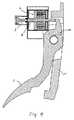
車両速度を制御するため図4に示されている装置は、ペダル6、ペダル角を検出するセンサ10、戻し素子8及び電気−機械戻し装置7を含んでいる。ペダル6はペダル保持体11に回転可能に設けられている。ペダル保持体11は、図示しないやり方で車体に結合されている。電気−機械戻し装置7は、その制御信号を図示しない制御装置から得る。 The device shown in FIG. 4 for controlling the vehicle speed includes a pedal 6, a
電気−機械戻し装置7は、図示した実施例では可動コイル操作器として構成されている。例えば直線運動又は回転運動も行うことができる電磁石を使用することも考えられる。戻し素子8はここでは機械的ばねである。 The electromechanical return device 7 is configured as a moving coil operator in the illustrated embodiment. For example, it is conceivable to use an electromagnet that can also perform linear motion or rotational motion. The return element 8 is here a mechanical spring.
ペダル6は、車両速度を増大するため、運転者の足により速度を上昇する方向に操作される。逆方向へのペダル6の操作は、一般に可動コイル操作器7、機械的戻しばね8及びヒステリシス素子9を介して行われて、速度減少を行う。可動コイル操作器7がその機能を一緒に引受けることによって、ヒステリシス素子9を有利に省くことができる。 The pedal 6 is operated in the direction of increasing the speed by the driver's foot in order to increase the vehicle speed. The operation of the pedal 6 in the reverse direction is generally performed via the moving coil operating device 7, the mechanical return spring 8, and the hysteresis element 9, and the speed is reduced. The hysteretic element 9 can be advantageously omitted by the moving coil operator 7 taking on the function together.
可動コイル操作器7が、エネルギ節約のため又は欠陥のため意図的に無電流で作動せしめられる場合、戻しばね8は、ペダル6が可能な最大偏向からペダル角0まで動かされる時間が特定の値を上回らないようにする。戻しばね8により発生される優勢な最小力より大きい力をペダル6に抗して実現するため、可能なあらゆるペダル角において、可動コイル操作器により発生される任意の力を加算することができる。 If the moving coil actuator 7 is actuated deliberately with no current for energy savings or defects, the return spring 8 has a certain value for the time that the pedal 6 is moved from the maximum possible deflection to the
可動コイル操作器7とペダル6との間には、機械的又は別の性質の固定的結合部はない。それによりペダル6には、1つの方向しかも速度減少の方向のみ、反力を及ぼすことができる。 There is no mechanical or other fixed connection between the moving coil actuator 7 and the pedal 6. As a result, the reaction force can be exerted on the pedal 6 only in one direction and in the direction of decreasing speed.
1 進行特性曲線
1a Pw sollまでの進行特性曲線
1b Pw sollからの進行特性曲線
2 ヒステリシス線
3 逆行特性曲線
3a Pw sollより後の逆行特性曲線
4 最小特性曲線
5 同時に反力を増大する際間隔を増大するか速度を減少するための特性曲線
6 ペダル
7 戻し装置
8 戻しばね
9 ヒステリシス素子
10 ペダル角センサ
11 ペダル保持体DESCRIPTION OF SYMBOLS 1 Progression
Claims (9)
Translated fromJapaneseApplications Claiming Priority (2)
| Application Number | Priority Date | Filing Date | Title |
|---|---|---|---|
| DE102004022222 | 2004-05-04 | ||
| PCT/DE2005/000835WO2005105508A1 (en) | 2004-05-04 | 2005-05-04 | Method and device for generating a pedal characteristic |
Publications (1)
| Publication Number | Publication Date |
|---|---|
| JP2007536166Atrue JP2007536166A (en) | 2007-12-13 |
Family
ID=34969639
Family Applications (1)
| Application Number | Title | Priority Date | Filing Date |
|---|---|---|---|
| JP2007513669APendingJP2007536166A (en) | 2004-05-04 | 2005-05-04 | Method and apparatus for realizing a pedal characteristic curve |
Country Status (3)
| Country | Link |
|---|---|
| JP (1) | JP2007536166A (en) |
| DE (1) | DE112005000630A5 (en) |
| WO (1) | WO2005105508A1 (en) |
Cited By (5)
| Publication number | Priority date | Publication date | Assignee | Title |
|---|---|---|---|---|
| JP2010250762A (en)* | 2009-04-20 | 2010-11-04 | Honda Motor Co Ltd | Reaction force device |
| JP2012056425A (en)* | 2010-09-08 | 2012-03-22 | Tokai Rika Co Ltd | Force sense imparting type shift device |
| JP2012526943A (en)* | 2009-05-15 | 2012-11-01 | コンティ テミック マイクロエレクトロニック ゲゼルシャフト ミット ベシュレンクテル ハフツング | Speed adjustment method and apparatus |
| CN112537199A (en)* | 2019-09-20 | 2021-03-23 | 丰田自动车株式会社 | Pedal device for vehicle |
| JP2022045171A (en)* | 2020-09-08 | 2022-03-18 | 株式会社デンソー | Brake system |
Families Citing this family (8)
| Publication number | Priority date | Publication date | Assignee | Title |
|---|---|---|---|---|
| DE102009006748A1 (en)* | 2009-01-30 | 2010-08-05 | Bayerische Motoren Werke Aktiengesellschaft | Speed governor for regulating speed to preset set point speed of passenger car, has acceleration element, where speed control accelerator pedal characteristic differs from basic pedal characteristic during speed controlling of element |
| EP2451688A1 (en)* | 2009-07-09 | 2012-05-16 | Conti Temic Microelectronic GmbH | Device for generating an additional restoring force at the gas pedal and method for the operation thereof |
| KR20130064083A (en) | 2010-05-11 | 2013-06-17 | 콘티 테믹 마이크로일렉트로닉 게엠베하 | Drive pedal unit for motor vehicles |
| DE102013213050A1 (en)* | 2013-07-04 | 2015-01-08 | Conti Temic Microelectronic Gmbh | Accellerator Force Feedback Pedal (AFFP) as an assistance system for distance control in road traffic |
| DE102013221973A1 (en)* | 2013-10-29 | 2015-05-13 | Conti Temic Microelectronic Gmbh | Method for determining a desired angle, in particular for a pedal pre-device, to assist in maintaining a setpoint speed |
| DE102016203395A1 (en) | 2016-03-02 | 2017-09-07 | Bayerische Motoren Werke Aktiengesellschaft | Pedal system for a trained at least partially automated driving vehicle |
| DE102016203398A1 (en)* | 2016-03-02 | 2017-09-07 | Bayerische Motoren Werke Aktiengesellschaft | Device for controlling the longitudinal guidance of a vehicle designed for at least partially automated driving |
| US10359802B2 (en) | 2016-08-22 | 2019-07-23 | Cts Corporation | Variable force electronic vehicle clutch pedal |
Citations (3)
| Publication number | Priority date | Publication date | Assignee | Title |
|---|---|---|---|---|
| JPH1044825A (en)* | 1996-07-30 | 1998-02-17 | Naldec Kk | Structure for vacuum pump type constant-speed drive system |
| JP2000054860A (en)* | 1998-08-10 | 2000-02-22 | Denso Corp | Automatic traveling control device, pedal reaction regulator and recording medium |
| JP2002323930A (en)* | 2001-04-25 | 2002-11-08 | Hitachi Ltd | Vehicle pedal device and vehicle equipped with the same |
Family Cites Families (3)
| Publication number | Priority date | Publication date | Assignee | Title |
|---|---|---|---|---|
| FR2725944B1 (en)* | 1994-10-24 | 1996-12-13 | Noel Jean Pierre | VEHICLE SPEED LIMITING DEVICE, ACTING ON A STOPPER LIMITING THE STROKE OF THE ACCELERATOR PEDAL |
| DE19620929A1 (en) | 1996-05-24 | 1997-11-27 | Porsche Ag | Longitudinal control system for motor vehicles with accelerator pedal with feel characteristic |
| JP3531640B2 (en)* | 2002-01-10 | 2004-05-31 | 日産自動車株式会社 | Driving operation assist device for vehicles |
- 2005
- 2005-05-04WOPCT/DE2005/000835patent/WO2005105508A1/enactiveApplication Filing
- 2005-05-04DEDE112005000630Tpatent/DE112005000630A5/ennot_activeCeased
- 2005-05-04JPJP2007513669Apatent/JP2007536166A/enactivePending
Patent Citations (3)
| Publication number | Priority date | Publication date | Assignee | Title |
|---|---|---|---|---|
| JPH1044825A (en)* | 1996-07-30 | 1998-02-17 | Naldec Kk | Structure for vacuum pump type constant-speed drive system |
| JP2000054860A (en)* | 1998-08-10 | 2000-02-22 | Denso Corp | Automatic traveling control device, pedal reaction regulator and recording medium |
| JP2002323930A (en)* | 2001-04-25 | 2002-11-08 | Hitachi Ltd | Vehicle pedal device and vehicle equipped with the same |
Cited By (9)
| Publication number | Priority date | Publication date | Assignee | Title |
|---|---|---|---|---|
| JP2010250762A (en)* | 2009-04-20 | 2010-11-04 | Honda Motor Co Ltd | Reaction force device |
| JP2012526943A (en)* | 2009-05-15 | 2012-11-01 | コンティ テミック マイクロエレクトロニック ゲゼルシャフト ミット ベシュレンクテル ハフツング | Speed adjustment method and apparatus |
| JP2012056425A (en)* | 2010-09-08 | 2012-03-22 | Tokai Rika Co Ltd | Force sense imparting type shift device |
| CN112537199A (en)* | 2019-09-20 | 2021-03-23 | 丰田自动车株式会社 | Pedal device for vehicle |
| JP2021047831A (en)* | 2019-09-20 | 2021-03-25 | トヨタ自動車株式会社 | Vehicular pedal device |
| US11541753B2 (en) | 2019-09-20 | 2023-01-03 | Toyota Jidosha Kabushiki Kaisha | Vehicular pedal device |
| JP7215383B2 (en) | 2019-09-20 | 2023-01-31 | トヨタ自動車株式会社 | Vehicle pedal device |
| CN112537199B (en)* | 2019-09-20 | 2024-07-26 | 丰田自动车株式会社 | Pedal device for vehicle |
| JP2022045171A (en)* | 2020-09-08 | 2022-03-18 | 株式会社デンソー | Brake system |
Also Published As
| Publication number | Publication date |
|---|---|
| WO2005105508A1 (en) | 2005-11-10 |
| DE112005000630A5 (en) | 2007-05-24 |
Similar Documents
| Publication | Publication Date | Title |
|---|---|---|
| JP2022518472A (en) | Control unit that provides one-pedal feeling and / or creep function | |
| US11214295B2 (en) | Steering control system | |
| JP7537306B2 (en) | Brake system and electronic control unit | |
| JP2007536166A (en) | Method and apparatus for realizing a pedal characteristic curve | |
| FR2828450B1 (en) | STARTING ASSISTANCE DEVICE FOR A MOTOR VEHICLE | |
| JP7207269B2 (en) | Pedal reaction force controller | |
| JP5602839B2 (en) | Speed adjustment method and apparatus | |
| JP2012500742A (en) | Vehicle speed control system | |
| CN108778883B (en) | Driver assistance system in motor vehicle and control method thereof | |
| JP2011517634A (en) | Method and apparatus for driving a vehicle with a hybrid drive | |
| JP2007137152A (en) | Accelerator pedal device | |
| JP6605142B2 (en) | Method and apparatus for driving an automobile brake system, brake system | |
| US6793234B2 (en) | Steering wheel feedback mechanism | |
| JP2017095067A (en) | Stop retaining device for vehicle | |
| JP2001171497A (en) | Anti-collision device for vehicles | |
| JP3956948B2 (en) | VEHICLE DRIVE OPERATION ASSISTANCE DEVICE AND VEHICLE HAVING VEHICLE DRIVE OPERATION ASSISTANCE DEVICE | |
| JP6387915B2 (en) | Vehicle driving support control device | |
| JPWO2022168733A5 (en) | ||
| JP4645378B2 (en) | Vehicle control device | |
| JP4255889B2 (en) | Assist control method for automatic transmission for vehicle | |
| JP2008110619A (en) | Brake control device for vehicle | |
| JP2020001524A (en) | Vehicle control device | |
| JP7351014B2 (en) | On-demand driving control system with on-demand driving pedals | |
| CN107524531B (en) | Device and method for operating an internal combustion engine of a motor vehicle | |
| JP3689953B2 (en) | Braking force holding device for electric vehicle |
Legal Events
| Date | Code | Title | Description |
|---|---|---|---|
| A621 | Written request for application examination | Free format text:JAPANESE INTERMEDIATE CODE: A621 Effective date:20080319 | |
| A131 | Notification of reasons for refusal | Free format text:JAPANESE INTERMEDIATE CODE: A131 Effective date:20100810 | |
| A601 | Written request for extension of time | Free format text:JAPANESE INTERMEDIATE CODE: A601 Effective date:20101109 | |
| A602 | Written permission of extension of time | Free format text:JAPANESE INTERMEDIATE CODE: A602 Effective date:20101207 | |
| A02 | Decision of refusal | Free format text:JAPANESE INTERMEDIATE CODE: A02 Effective date:20110412 |