JP2007533407A - Surgical instrument suction valve - Google Patents
Surgical instrument suction valveDownload PDFInfo
- Publication number
- JP2007533407A JP2007533407AJP2007509539AJP2007509539AJP2007533407AJP 2007533407 AJP2007533407 AJP 2007533407AJP 2007509539 AJP2007509539 AJP 2007509539AJP 2007509539 AJP2007509539 AJP 2007509539AJP 2007533407 AJP2007533407 AJP 2007533407A
- Authority
- JP
- Japan
- Prior art keywords
- surgical instrument
- shaft
- hub
- opening
- hole
- Prior art date
- Legal status (The legal status is an assumption and is not a legal conclusion. Google has not performed a legal analysis and makes no representation as to the accuracy of the status listed.)
- Granted
Links
- 230000033001locomotionEffects0.000claimsabstractdescription21
- 238000000034methodMethods0.000claimsabstractdescription21
- 230000003252repetitive effectEffects0.000claimsabstractdescription9
- 230000008878couplingEffects0.000claimsdescription54
- 238000010168coupling processMethods0.000claimsdescription54
- 238000005859coupling reactionMethods0.000claimsdescription54
- 239000012530fluidSubstances0.000claimsdescription34
- 238000004891communicationMethods0.000claimsdescription17
- 230000008859changeEffects0.000claimsdescription5
- 230000007246mechanismEffects0.000description10
- 238000006073displacement reactionMethods0.000description3
- 230000000694effectsEffects0.000description2
- 238000007789sealingMethods0.000description2
- 239000007787solidSubstances0.000description2
- 239000000853adhesiveSubstances0.000description1
- 230000001070adhesive effectEffects0.000description1
- 230000009286beneficial effectEffects0.000description1
- 238000005553drillingMethods0.000description1
- 239000003822epoxy resinSubstances0.000description1
- 238000009802hysterectomyMethods0.000description1
- 210000003127kneeAnatomy0.000description1
- 239000000463materialSubstances0.000description1
- 238000012986modificationMethods0.000description1
- 230000004048modificationEffects0.000description1
- 229920000647polyepoxidePolymers0.000description1
- 230000009467reductionEffects0.000description1
- 238000001356surgical procedureMethods0.000description1
- 238000003466weldingMethods0.000description1
Images


Classifications
- A—HUMAN NECESSITIES
- A61—MEDICAL OR VETERINARY SCIENCE; HYGIENE
- A61B—DIAGNOSIS; SURGERY; IDENTIFICATION
- A61B17/00—Surgical instruments, devices or methods
- A61B17/32—Surgical cutting instruments
- A61B17/320016—Endoscopic cutting instruments, e.g. arthroscopes, resectoscopes
- A61B17/32002—Endoscopic cutting instruments, e.g. arthroscopes, resectoscopes with continuously rotating, oscillating or reciprocating cutting instruments
- A—HUMAN NECESSITIES
- A61—MEDICAL OR VETERINARY SCIENCE; HYGIENE
- A61M—DEVICES FOR INTRODUCING MEDIA INTO, OR ONTO, THE BODY; DEVICES FOR TRANSDUCING BODY MEDIA OR FOR TAKING MEDIA FROM THE BODY; DEVICES FOR PRODUCING OR ENDING SLEEP OR STUPOR
- A61M1/00—Suction or pumping devices for medical purposes; Devices for carrying-off, for treatment of, or for carrying-over, body-liquids; Drainage systems
- A61M1/71—Suction drainage systems
- A61M1/74—Suction control
- A—HUMAN NECESSITIES
- A61—MEDICAL OR VETERINARY SCIENCE; HYGIENE
- A61B—DIAGNOSIS; SURGERY; IDENTIFICATION
- A61B10/00—Instruments for taking body samples for diagnostic purposes; Other methods or instruments for diagnosis, e.g. for vaccination diagnosis, sex determination or ovulation-period determination; Throat striking implements
- A61B10/02—Instruments for taking cell samples or for biopsy
- A61B10/0233—Pointed or sharp biopsy instruments
- A61B10/0283—Pointed or sharp biopsy instruments with vacuum aspiration, e.g. caused by retractable plunger or by connected syringe
- A—HUMAN NECESSITIES
- A61—MEDICAL OR VETERINARY SCIENCE; HYGIENE
- A61B—DIAGNOSIS; SURGERY; IDENTIFICATION
- A61B2217/00—General characteristics of surgical instruments
- A61B2217/002—Auxiliary appliance
- A61B2217/005—Auxiliary appliance with suction drainage system
- A—HUMAN NECESSITIES
- A61—MEDICAL OR VETERINARY SCIENCE; HYGIENE
- A61M—DEVICES FOR INTRODUCING MEDIA INTO, OR ONTO, THE BODY; DEVICES FOR TRANSDUCING BODY MEDIA OR FOR TAKING MEDIA FROM THE BODY; DEVICES FOR PRODUCING OR ENDING SLEEP OR STUPOR
- A61M1/00—Suction or pumping devices for medical purposes; Devices for carrying-off, for treatment of, or for carrying-over, body-liquids; Drainage systems
- A61M1/71—Suction drainage systems
- A61M1/74—Suction control
- A61M1/75—Intermittent or pulsating suction
- A—HUMAN NECESSITIES
- A61—MEDICAL OR VETERINARY SCIENCE; HYGIENE
- A61M—DEVICES FOR INTRODUCING MEDIA INTO, OR ONTO, THE BODY; DEVICES FOR TRANSDUCING BODY MEDIA OR FOR TAKING MEDIA FROM THE BODY; DEVICES FOR PRODUCING OR ENDING SLEEP OR STUPOR
- A61M1/00—Suction or pumping devices for medical purposes; Devices for carrying-off, for treatment of, or for carrying-over, body-liquids; Drainage systems
- A61M1/84—Drainage tubes; Aspiration tips
Landscapes
- Health & Medical Sciences (AREA)
- Life Sciences & Earth Sciences (AREA)
- Surgery (AREA)
- Heart & Thoracic Surgery (AREA)
- Public Health (AREA)
- Animal Behavior & Ethology (AREA)
- Biomedical Technology (AREA)
- Veterinary Medicine (AREA)
- Engineering & Computer Science (AREA)
- General Health & Medical Sciences (AREA)
- Medical Informatics (AREA)
- Molecular Biology (AREA)
- Orthopedic Medicine & Surgery (AREA)
- Nuclear Medicine, Radiotherapy & Molecular Imaging (AREA)
- Vascular Medicine (AREA)
- Anesthesiology (AREA)
- Hematology (AREA)
- Surgical Instruments (AREA)
- External Artificial Organs (AREA)
Abstract
Translated fromJapaneseDescription
Translated fromJapanese本発明は、外科用器具の吸引弁に関する。 The present invention relates to a suction valve for a surgical instrument.
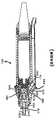
図1及び2を参照すると、外側の非回転管370と回転カッター300の内側回転シャフト374との間に配置された組織を、管内に管を配置した構造を使用して切除するために使用される従来技術による外科用器具が示されており、この外科用器具は米国特許5,871,493に更に詳細に説明されている。外側管370は、基端領域371においてハブ320に結合されており、内側回転シャフト374は、ハブ320及び外側管内に回転可能に収容されている。内側回転シャフト374は、外側管370内に配置されている管376を含んでいる。管376は、吸引内腔378を規定しており且つ内側シャフト374の基端領域に配置され且つハブ320内に一部が収容されているモーターカップリングに結合されている。モーターカップリング350は、駆動機構115に結合された伸長部355を含んでおり、駆動機構115は、内側シャフト374をハブ320及び外側管370に対して回転させる。ハブ320は、米国特許5,871,493に説明されているように、回転カッター300をハンドピース100に結合するための弾性ラッチ機構310の形態のカップリングを備えている。特に、ラッチ機構310は、傾斜が付けられたラッチ330を備えた片持ち梁状弾性アーム315を含んでおり、当該ラッチ330は、米国特許5,871,493の図7Bに図示されているように、回転カッター300をハンドピース100に軸線方向において固定するためにハンドピース100内の環状のフランジ610と係合している。ラッチ機構の他の実施形態もまた米国特許5,871,493に記載されている。 With reference to FIGS. 1 and 2, the tissue placed between the outer
ハンドピース100(図2)は、外科部位から流体を除去し且つ組織を切除するために吸引内腔378に吸引力を適用するための吸引穴633で終端している吸引チャネル630を備えている。シャフト374の管376内の吸引内腔378は、モーターカップリング350内の貫通穴380と連通している基端の穴375を備えている。外側管370の側方に面している窓305及び内側管376の側方に面した窓307を介して内腔378内へ及び内腔の穴375及び穴380の両端を介して吸引チャネル630へと物質を抜き取るために吸引力が適用される。 Handpiece 100 (FIG. 2) includes a
図1及び2の外科用器具においては、モーターカップリング350の貫通穴380は、ハンドピースのモーターカップリング350と内壁622との間の隙間により、貫通穴380の回転位置に関係なく回転カッター300がハンドピース100内へ挿入されたときに吸引チャネル630と連通する。しかしながら、外側管の窓305が内側管の窓307を一時的に重なることにより吸引の自動的な調整が提供される。なぜならば、内側管376を介する吸引は、窓が少なくとも実質的に部分的に整合されているときにのみ起こるからである。吸引は連続的でないので、外科部位からの余分な流体の除去に伴う本質的な問題が生じない。 In the surgical instrument of FIGS. 1 and 2, the
例えば、外科用環境に対して常に又は殆ど常に開口している端部が開口しているバリ及び直線に沿って往復するカッターのような切削ブレードのような上記した側方カッターと異なる末端形状を備えた外科用器具は、吸引を自動的に調節しない。 For example, different end shapes than the side cutters described above, such as cutting burrs such as burrs that are open to the surgical environment, or burrs that are always open to the surgical environment and reciprocating along a straight line. The provided surgical instrument does not automatically adjust the suction.
本発明の一つの特徴によれば、外科用器具のハブは、可動部材を収容するためのチャネルを規定している壁を備えている本体を含んでいる。当該壁は、前記可動部材が動くと当該可動部材の穴との流体連通の程度を変更できる構造とされた開口を規定している。前記本体は、当該本体をハンドルに係合させる構造とされたカップリングを含んでいる。 According to one aspect of the invention, the hub of the surgical instrument includes a body having a wall defining a channel for receiving a movable member. The wall defines an opening configured to change the degree of fluid communication with the hole of the movable member when the movable member moves. The body includes a coupling configured to engage the body with a handle.
この特徴の実施形態は以下の特徴のうちの1以上を含むことができる。前記壁に設けられた開口は、前記可動部材内の穴と一時的に重なる構造とされている。前記ハブの壁に設けられた開口は前記チャネルと流体連通している。当該壁は第二の開口を規定している。前記カップリングは、ハブをハンドピースに結合するための弾性部材を含んでいる。前記壁において前記開口を取り巻いている少なくとも一部分は傾斜端縁を備えている。 Embodiments of this feature can include one or more of the following features. The opening provided in the wall has a structure that temporarily overlaps the hole in the movable member. An opening in the hub wall is in fluid communication with the channel. The wall defines a second opening. The coupling includes an elastic member for coupling the hub to the handpiece. At least a portion of the wall surrounding the opening has an inclined edge.
もう一つ別の特徴によれば、外科用器具は、基端端縁に穴を規定しているシャフトと、当該シャフトが動くと前記シャフトの穴との流体連通の程度を変えることができる構造とされた開口を規定しているハブとを含んでいる。 According to another feature, the surgical instrument has a structure that defines a hole in the proximal end edge and the degree of fluid communication between the shaft hole when the shaft moves. And a hub defining a defined opening.
この特徴の実施形態は以下の特徴のうちの1以上を含むことができる。前記シャフトに設けられた穴は、前記シャフトが動くと前記ハブの開口と一時的に重なる構造とされている。前記ハブは、前記シャフトを収容するためのチャネルを規定している壁を有している。このハブは、当該ハブをハンドルに結合する構造とされたカップリングを含んでいる。前記シャフトは、当該シャフトに設けられた前記穴と流体連通している内腔を規定している。前記シャフトは、当該シャフトの内腔と流体連通している末端開口を含んでいる。前記外科用器具は、前記シャフトを包囲し且つ前記ハブに結合されている外側管と、前記ハブに結合されたハンドルとを含んでいる。 Embodiments of this feature can include one or more of the following features. The hole provided in the shaft is configured to temporarily overlap the opening of the hub when the shaft moves. The hub has a wall defining a channel for receiving the shaft. The hub includes a coupling configured to couple the hub to the handle. The shaft defines a lumen in fluid communication with the hole provided in the shaft. The shaft includes a distal opening in fluid communication with the shaft lumen. The surgical instrument includes an outer tube surrounding the shaft and coupled to the hub, and a handle coupled to the hub.
もう一つ別の特徴による方法は、外科用器具の内腔を介して流体を吸引することと、流体の吸引を制限するために前記内腔の基端領域の内腔と流体連通している開口を自動的に一時的に実質的に閉塞することとを含んでいる。 According to another feature, a method for aspirating fluid through a lumen of a surgical instrument and in fluid communication with a lumen in a proximal region of the lumen to limit fluid aspiration Automatically and substantially occluding the opening.
この特徴による実施形態は、以下の特徴の1以上を含むことができる。穴が前記外科用器具のシャフト内に設けられ、前記穴と自動的に一時的に実質的に重なるステップは、前記ハブの開口が前記シャフトの穴との整合状態から一時的にずれるように前記シャフトを前記外科用器具のハブに対して動かすことを含んでいる。前記シャフトを動かすステップは、例えば前記シャフトを回転させること又は前記シャフトを振動させることを含む。前記シャフトは第二の穴を規定し、前記シャフトを回転させるステップは、前記開口を前記第二の開口との整合状態から一時的にずれさせる。 Embodiments according to this feature can include one or more of the following features. A step in which a hole is provided in the surgical instrument shaft and automatically and substantially overlaps with the hole is such that the opening of the hub is temporarily offset from alignment with the hole in the shaft. Moving the shaft relative to the hub of the surgical instrument. The step of moving the shaft includes, for example, rotating the shaft or vibrating the shaft. The shaft defines a second hole, and the step of rotating the shaft temporarily shifts the opening from alignment with the second opening.
別の特徴による外科用器具を介する吸引を調整する方法は、基端部分に穴を備えている可動部材と開口を有する固定部材との間に緊密な嵌合を提供して実質的に前記可動部材の繰り返し動作中の一部分においてのみ前記可動部材を介する吸引が生じるようにさせるステップを含んでいる。前記可動部材と固定部材とは、前記可動部材に吸引及び動きを提供するように外科用ハンドピースに結合されている。この特徴の実施形態は、以下の特徴のうちの1以上を含むことができる。前記可動部材の前記繰り返し動作中の一部分において、前記可動部材の穴は前記固定部材の開口に少なくとも部分的に重なる。 According to another aspect, a method for adjusting suction through a surgical instrument provides a tight fit between a movable member having a hole in a proximal portion and a fixed member having an opening to substantially move the movable member. A step of causing suction through the movable member to occur only in a part during the repetitive operation of the member. The movable member and the fixed member are coupled to a surgical handpiece to provide suction and movement to the movable member. Embodiments of this feature can include one or more of the following features. In a part of the movable member during the repeated operation, the hole of the movable member at least partially overlaps the opening of the fixed member.
もう一つ別の特徴による外科用器具は、基端部分を有している可動部材を含んでおり、前記可動部材は基端部分に穴を規定している。当該器具は、開口を規定している固定部材を含んでいる。前記固定部材は、実質的に前記可動部材の繰り返し動作中の一部分においてのみ前記可動部材を介する吸引が生じるように前記固定部材と前記可動部材とが緊密な嵌合した状態で前記可動部材に対して配置されている。当該器具は、前記可動部材に吸引力及び動きを提供するために前記可動部材及び前記固定部材に結合された外科用ハンドピースを含んでいる。 According to another aspect, a surgical instrument includes a movable member having a proximal portion, the movable member defining a hole in the proximal portion. The instrument includes a securing member that defines an opening. The fixed member is in contact with the movable member in a state in which the fixed member and the movable member are closely fitted so that suction through the movable member occurs substantially only in a part during the repeated operation of the movable member. Are arranged. The instrument includes a surgical handpiece coupled to the movable member and the stationary member to provide suction and movement to the movable member.
この特徴による実施形態は、以下の特徴のうちの1以上を含むことができる。前記固定部材は、前記可動部材の繰り返し動作の一部分において前記可動部材の穴が一時的に前記固定部材の開口と重なるように前記可動部材に対して配置されている。前記固定部材は前記開口を規定しているハブを含んでおり、当該ハブは前記外科用ハンドピースに結合する構造とされたカップリングを含んでいる。 Embodiments according to this feature can include one or more of the following features. The fixed member is disposed with respect to the movable member such that a hole of the movable member temporarily overlaps an opening of the fixed member in a part of the repetitive operation of the movable member. The securing member includes a hub defining the opening, the hub including a coupling configured to couple to the surgical handpiece.
例えば吸引力が部材に適用される領域に前記可動部材と前記固体部材との間に緊密な嵌合を有する外科用器具は流体の過剰な使用という問題を解決する。外科用器具の直径を小さくして詰まりを生じさせ得ることなく流体の使用の減少が達成される。当該外科用器具は、経頸管的子宮線維切除のような流体の除去を補償するために外科部位の流体の体積を増大させることが実用的でない環境及び過剰な流体の除去が膝のような関節内の閉塞された手術のような外科部位周囲の圧潰を生じさせ得る環境における使用に特に適用可能である。 For example, a surgical instrument having a tight fit between the movable member and the solid member in the area where a suction force is applied to the member solves the problem of excessive use of fluid. Reduction in fluid use is achieved without reducing the diameter of the surgical instrument and causing clogging. The surgical instrument is used in environments where it is impractical to increase the volume of fluid at the surgical site to compensate for fluid removal such as transcervical hysterectomy and joints such as knees where excessive fluid removal is impractical. It is particularly applicable for use in an environment that can cause crushing around the surgical site, such as internal occlusion surgery.
1以上の実施形態の細部を添付図面及び以下の詳細な説明に記載する。他の特徴は、前記詳細な説明及び特許請求の範囲によって明らかとなるであろう。 The details of one or more embodiments are set forth in the accompanying drawings and the detailed description below. Other features will be apparent from the detailed description and from the claims.
図3及び4を参照すると、回転カッター10例えば端部が開口しているバリカッターは、末端の刃物が異なるタイプであるが、図1に関して上記した外側管370a及び内側シャフト374aとを含んでいる。外側管370aは、カッター10をハンドピース100に結合するためにラッチ機構310に関して上記した弾性ラッチ機構310aを備えているハブ15に結合されている。ハブ15には、実質的にハブ320に関して上記したように、細長いチャネル22を規定している壁20と、壁20内に延びており且つチャネル22と流体連通している開口26を有している基端方向に延びている本体18とが付加されている。 Referring to FIGS. 3 and 4, a
開口26は、モーターカップリング350aの側方穴380aの領域内でシャフト374aのモーターカップリング350aを覆うように配置されており、シャフト374aがハブ15に対して回転すると開口26が側方穴380aを一時的に覆って吸引弁60を形成するようにされている。側方穴380aは、図1の穴380内とは反対にモーターカップリング350a内に部分的にのみ延びている。開口26は、壁20の側方端縁28によって部分的に規定されている。側方端縁28は、組織が開口26内に収容された状態になったときに組織を切り取るように傾斜が付けられている。モーターカップリング350aに側方穴380aを規定している端縁58は、組織を切り取る際に側方端縁28と協働するように鋭利になされている。端縁58は、組織を切り取らない位置は鋭利である必要はない。 The
図5を参照すると、シャフト374aの回転動作の一部分中に、開口26は、側方穴380aの一部分又は全てが開口26を介して曝されて内側管の内腔378に吸引力を付与できるように側方穴380aに重なる。図6は、開口26が側方穴380aに重ならないように図5に対して180度回転せしめられたシャフト374aを示している。本体18は、開口26が側方穴380aに重なっていないときに側方穴380aが壁20の内面29によって殆ど完全に遮断されて管の内腔378に対する吸引力の適用を制限するようにモーターカップリング350aを包囲している。特別な実施形態においては、モーターカップリング350aの外面59と壁20の内面29との間の隙間は、管376に対する吸引力の適用従って管376を介する流体の取り出しを制限する吸引弁60が形成されるようにモーターカップリング350aと壁20との間に緊密な嵌合を提供するために、約0.001インチ(0.0254mm)乃至約0.010インチ(0.254mm)の範囲内、好ましくは約0.001インチ(0.0254mm)乃至約0.005インチ(0.127mm)の範囲内、最も好ましくは約0.001インチ(0.0254mm)乃至約0.002インチ(0.0508mm)の範囲内である。 Referring to FIG. 5, during a portion of the rotational movement of the
他の実施形態においては、種々のファクタに依存してより大きな又はより小さい隙間を使用しても良い。このようなファクタの一つは、外科用器具が例えば図1の側方穴開け回転カッター300のように側方から装填されるか否かであり、これはモーターカップリングの横方向への変位を受け且つ底摩擦を維持するためにより大きな隙間を必要とし得る。他のファクタとしては、例えば、(i)吸引流体速度(より速い流体速度は、恐らくより大きな隙間及びより大きな漏れを許容し且つ吸引の十分な制限を依然として提供する)及び(ii)管を使用している実施形態に対して使用されている管の直径(より大きな直径は恐らくより速い流速を提供し、従って、より大きな隙間を許容する)がある。過剰な隙間は、外面59の周囲での詰まり及び環状の漏れの一因となり得る。環状の漏れを最少化するためにはシールを提供することができ、これは大きな隙間に対して特に有用であり得る。 In other embodiments, larger or smaller gaps may be used depending on various factors. One such factor is whether or not the surgical instrument is loaded from the side, such as the side-
このようにして、開口26及び側方穴380aは、カッター10を介する吸引力の適用を自動的に調整するための吸引弁60を形成する。弁60の作動によって、例えば、内側管376の直径を減じることなく又はオペレータが弁を手動によって開いたり閉じたりする必要なくカッター10を介する吸引が制限される。吸引力の一時的な適用によって、シャフト374aが回転する間にカッター10を介する吸引が制限される。吸引はまた、側方穴380aが開口26との整合状態からずれた状態にシャフト374aが配置されているときにシャフト374aの回転を停止させることによってシャフト364aが静止しているときに制限され得る。このような停止機構は、米国特許5,602,449に記載されており、当該特許はその全体が参考として本明細書内に組み入れられている。 In this way, the
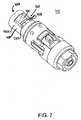
他の実施形態は特許請求の範囲内に含まれている。例えば、図7を参照すると、ハブ710は、長手チャネル722を規定している壁720を有している基端方向に延びている本体718と、壁720内に延びており且つチャネル722と流体連通している第一及び第二の開口726,727を含んでいる。開口726及び727は、部分的に、組織を切り取るために傾斜が付けられた端縁728によって規定されている。開口726,727がモーターカップリング350a内の側方穴380aと重なっているときに内側管の内腔378に吸引力が適用されて、ハブ15と協働して大きな吸引力を付与する。このようにして、側方穴380aに沿った穴726及び727は自動的に調整される吸引のための吸引弁760を形成している。 Other embodiments are within the scope of the claims. For example, referring to FIG. 7, the
他の実施形態においては、ハブ以外の構造が吸引を制限するために使用されている。例えば、図8を参照すると、回転カッター800は、開口26bを規定している基端部分802を備えている固定の外側管370bを含んでいる。カッター800はまた、側方穴380bを規定している基端部分804を備えている回転内側シャフト374bをも含んでいる。シャフト374bは、例えば駆動機構115のような駆動機構と協働するための基端伸長部355bを備えている。カッター800は更に、管370b及びシャフト374bがその中を伸長しているハブ320bを含んでいる。固定の外側管370bは、例えば、接着剤、エポキシ樹脂、溶着又はオーバーモールディングを使用することによってハブ320bに固定されており、ハブ320bは、例えば、ハンドピース100のようなハンドピースに結合される。ハブ320bは実質的には図1のハブ320と類似している。管370bの基端部分802は、図3のハブ15の本体20と類似した方法で作動し、開口26bと側方穴380bとが、カッター800による吸引の適用を自動的に調整するための吸引弁860を形成している。 In other embodiments, structures other than the hub are used to limit suction. For example, referring to FIG. 8, rotary cutter 800 includes a fixed outer tube 370b with a
吸引弁860は、例えば吸引弁60又は760よりも直径が小さい。この小さな直径により、弁860が閉じているときに弁860内に収容されるようになるかも知れない組織を切り取るのにより小さな力が必要とされる。より小さな直径により、弁60の近くでの壁20とモーターカップリング350aとの間よりも弁860の近くで管370bとシャフト374bとの間の接触のために利用できるより小さな表面積が存在する。この小さな表面積は、打ち勝つのに必要な力がより小さい少量の摩擦を形成する。この小さな摩擦はまた、既に説明した側方から装填される実施形態における横方向の変位作用の幾つかを緩和することもできる。側方から装填される実施形態における横方向の変位作用を更に緩和するためには、開口26と側方穴380bとは、管370bがハブ320bに取り付けられる位置(例えば、図5における結合点51を参照)に向かって末端方向へ動かされる。 The suction valve 860 has a smaller diameter than the
吸引を制限するためにハブ以外の構造を使用している別の実施形態は、図1及び2のモーターカップリング350と内壁622との間の隙間を減らすことによって達成される。例えば、モーターカップリング350aの外面59と壁20の内面29との間の隙間に関して上記したように隙間を減らすことによって、吸引弁は、吸引穴633及び吸引力の適用を自動的に調整するための穴380によって形成されている。 Another embodiment using a structure other than a hub to limit suction is achieved by reducing the clearance between the
図9を参照すると、モーターカップリング350cは、シール910例えばO−リングを含んでいる。シール910は、モーターカップリング350c内のキャビティ920内に配置されており、モーターカップリングは、他の点ではモーターカップリング350aと類似している。シール910は、モーターカップリング350cとハブ15との間にシール機能を提供する。特に、シール910は、壁20の内面29とモーターカップリング350cの外面59cとの間にシール機能を提供する。真空源がモーターカップリング350cに結合されると、この真空源は、壁20の基端930のみならず穴26内を通る意図された吸引経路に吸引力を適用する。シール900は、壁20とモーターカップリング350cとの間で基端930からの環状の漏れを制限して流体の吸引を減じる。他の実施形態は、漏れを制限するために、特別な用途に応じて付加的な又は代替的な位置にシールを使用することができる。 Referring to FIG. 9, the motor coupling 350c includes a
図10及び11を参照すると、モーターカップリング350dは、吸引を調節するために、ハブ15dの本体18dの部分的に円形の本体フランジ1020と協働する部分的に円形のカップリングフランジ1010を含んでいる。カップリングフランジ1010と本体フランジ1020とは、相互に長手方向に沿って配置されている。カップリングフランジ1010はカップリング穴1030を規定しており、本体フランジ1020は本体穴又は開口1040を規定している。カップリングフランジ1010は、モーターカップリング350dと共に回転して、モーターカップリング350dが回転するとカップリング穴1030が一時的に重なり且つ固体本体の穴1040と流体連通して吸引のための経路を提供するようになされている。図10は、本体の穴1040と完全に重なっているカップリング穴1030を示しており、一方、図11は、本体の穴1040と部分的にのみ重なっているカップリングの穴1030を示している。モーターカップリング350dは、カップリング穴1030と長手方向に整合している側方穴380a(図3)のような側方穴(図示せず)を含んでいる。他の実施形態は、カップリング穴1030に関して動かされた側方穴を有することができる。フランジ1010及び1020は、液密シールを形成することができ又は何らかの漏れを許容することができる。しかしながら、たとえ漏れが生じた場合でも、穴1030と1040との一時的な重なりは、穴1030及び1040が整合されたときに穴1030と1040との間の高い流体連通を提供する。 Referring to FIGS. 10 and 11, the
もう一つ別の実施形態は、ハブに対して再位置決めすることができる固定部材を提供している。例えば、このような実施形態のうちの一つは、本体18が形成されている。例えば、可動の本体はハブの長手軸線を中心に回転させることができる。可動本体は、例えば戻り止め部材を使用することによって特別な回転位置に係止することができ、実際の回転位置は、可動本体及び/又はハブ上に設けられた指標のような一組の標識を使用することによって示すことができる。このような回転動作は、図3の開口26と同様に、開口は、例えば吸引チャンバ630との整合を調整するために、種々の回転位置に位置決めすることができる。開口の整合を調整する方法としては、吸引を制限するために吸引チャネルとの整合を減じる方法又は吸引を増大させるために整合を増す方法がある。一つの実施形態は、1以上の位置においてハンドピースに結合することができるハブを使用しており、可動の本体は、ハブがハンドピースに対して如何なる位置にあっても可動本体内の穴がハンドピースの吸引チャネルと整合されることを可能にする。 Another embodiment provides a fixation member that can be repositioned relative to the hub. For example, in one such embodiment, a
以上、可動部材内の穴及び固定部材内の開口が、可動部材の繰り返し動作の一部分中において流体と連通するような構造とされている弁60、70及び80のような吸引弁の動作を説明した。流体連通は、弁60、760及び860のように、開口と穴とを重ねることによって達成することができる。重なりは、回転弁60、760及び860におけるように、開口と穴とを整合状態にして開口が穴と一時的に整合するようにさせる可動部材の回転動作によって達成することができる。この回転動作は、単一の回転方向とすることができ又は異なる方向へ前後に振動させることもできる。更に、弁の可動部材は、例えば、往復動と称される外科用器具の長手軸線に沿った前後方向の直線動作のような吸引を制限する他のタイプの動作を受けることができる。更に又は代替的に、弁は、例えば、第一の可動部材内の穴と第二の部材内の開口とを使用することによって、固定部材を使用することなく形成することができる。弁60、760、860は、例えば回転動作又は往復動作を使用する器具を含む種々のタイプの器具の吸引を制限し又は調整するために使用することができる。 The operation of the suction valve such as the
上記したように、何らかの吸引調整を既に付与している側方切断器具を備えた実施形態を使用することができる。このような実施形態は、側方切り取り装置の外科用窓(例えば、図1における窓305及び307)が開いているときに、例えば吸引力を制御する際の特別な値とすることができる吸引の付加的な調整を付与することができる。外科的な窓は、開けることができ、制限された吸引力は、可動の窓が例えばゆっくりとした速度で動いている間(例えば、図1における窓307が回転している間)か又は停止している間に有益なものとすることができる。外科的な窓に関する弁の位置及びタイミングは、用途に応じて変化させることができる。更に、弁の穴は、例えば、外科用窓より小さくすることができ或いは吸引された組織の付加的な切り取りを提供することができる。 As described above, embodiments with side cutting instruments that have already been provided with some suction adjustment can be used. Such an embodiment can provide a special value when controlling the suction force, for example when the surgical window (eg, windows 305 and 307 in FIG. 1) of the side clipping device is open. Additional adjustments can be made. The surgical window can be opened and the limited suction force can be applied while the movable window is moving at a slow speed (eg, while the window 307 in FIG. 1 is rotating) or stopped. It can be beneficial while you are. The position and timing of the valve relative to the surgical window can be varied depending on the application. In addition, the valve holes can be smaller than, for example, a surgical window or can provide additional cuts of aspirated tissue.
上記した実施形態及びその他の実施形態は、例えば、部材が穴間の流体連通レベルを変え、すなわち増大させ又は低減させ、従って、吸引レベルを変えるために動くと、2つの穴の相対的な位置が調整されるように作動させることによって吸引を調整することができる。穴は一時的に実質的に閉塞させることができ、吸引は実質的に繰り返し動作の一部分中においてのみ生じ得る。弁の可動部材と固定部材との間の隙間により及び吸引チャネル630からの吸引もまた適用されるそれらの基端における可動部材と固定部材との間の漏れにより、穴が完全に整合状態からずれたときにおいてさえ何らかの漏れは生じるであろう。 The embodiments described above and other embodiments, for example, when the member moves to change, i.e. increase or decrease, the fluid communication level between the holes and thus change the suction level, the relative position of the two holes. The suction can be adjusted by actuating so that is adjusted. The hole can be temporarily substantially occluded and suction can occur substantially only during a portion of the repetitive motion. Due to the gap between the movable member and the fixed member of the valve and due to leakage between the movable member and the fixed member at their proximal end where suction from the
以上、多くの実施形態を説明したが、それにも拘わらず、種々の変形を施すことができることは理解されるであろう。例えば、ハブの本体は、種々の大きさ及び形状のいずれかを有する異なる数の開口を規定することができ、モーターカップリングは、適用される吸引量を変えるために種々の大きさ及び形状のいずれかを有する異なる数の穴、側方穴又はその他のものを規定することができる。ハブ本体の開口及び/又はモーターカップリング内の穴は、異なる数の尖った端縁によって包囲することができ又は尖った端縁を全く有していなくても良い。モーターカップリングは、例えば、回転、バリカッター、往復カッター又はドリルのような種々のタイプの外科用器具に結合することができる。外科用器具は、例えば、一方向の回転、振動(交互方向の回転)、往復動(長手方向の動き)又はこれらの動作の組み合わせを含む種々の異なる動作を使用して作動することができる。ラッチ機構310aは、米国特許5,871,493に記載されている実施形態のうちのいずれかを使用することができる。 Although a number of embodiments have been described above, it will be understood that various modifications can be made nevertheless. For example, the hub body can define a different number of openings having any of a variety of sizes and shapes, and the motor coupling can be of various sizes and shapes to vary the amount of suction applied. A different number of holes, side holes or the like having either can be defined. The opening in the hub body and / or the hole in the motor coupling may be surrounded by a different number of sharp edges or may not have any sharp edges at all. The motor coupling can be coupled to various types of surgical instruments such as, for example, a rotary, burr cutter, reciprocating cutter or drill. Surgical instruments can be operated using a variety of different movements including, for example, unidirectional rotation, vibration (alternating rotation), reciprocation (longitudinal movement), or a combination of these movements. The
Claims (26)
Translated fromJapanese前記壁が、前記可動部材が動くと当該可動部材に設けられた穴との流体連通レベルを変えることができる構造とされた開口を規定していることを特徴とする外科用器具のハブ。A surgical instrument hub including a body including a coupling structured to couple the body to the handle, and further including a wall defining a channel for receiving the movable member;
The hub of a surgical instrument, wherein the wall defines an opening configured to change a fluid communication level with a hole provided in the movable member when the movable member moves.
前記壁の開口が前記可動部材の前記穴に一時的に重なるようになされた外科用器具のハブ。A surgical instrument hub according to claim 1,
A surgical instrument hub wherein the opening in the wall temporarily overlaps the hole in the movable member.
前記壁に設けられた開口が前記チャネルと流体連通している外科用器具のハブ。A surgical instrument hub according to claim 1 or 2,
A surgical instrument hub in which an opening in the wall is in fluid communication with the channel.
前記壁が第二の開口を画成している外科用器具のハブ。A surgical instrument hub according to any one of claims 1 to 3,
A surgical instrument hub, wherein the wall defines a second opening.
前記カップリングが前記ハブを前記ハンドルに結合するための弾性部材を含んでいる外科用器具のハブ。A surgical instrument hub according to any one of claims 1 to 4,
A surgical instrument hub, wherein the coupling includes a resilient member for coupling the hub to the handle.
前記壁の開口を取り巻いている当該壁の一部分が傾斜端縁を備えている外科用器具のハブ。A surgical instrument hub according to any one of claims 1 to 5,
A surgical instrument hub, wherein a portion of the wall surrounding the wall opening has a beveled edge.
前記ハブが、前記シャフトが動くと当該シャフトに規定された前記穴との流体連通の程度を変える構造とされている開口を規定していることを特徴とする外科用器具。A surgical instrument comprising a hub and a shaft defining a hole in the proximal region;
A surgical instrument characterized in that the hub defines an opening configured to change the degree of fluid communication with the hole defined in the shaft as the shaft moves.
前記シャフトが動くと、前記ハブが規定している開口が前記シャフトが規定している穴と一時的に重なる構造とされている外科用器具。The surgical instrument according to claim 7,
A surgical instrument configured such that when the shaft moves, an opening defined by the hub temporarily overlaps a hole defined by the shaft.
前記ハブが、前記シャフトを収容するためのチャネルを規定している壁を備えている外科用器具。The surgical instrument according to claim 7 or 8,
A surgical instrument wherein the hub includes a wall defining a channel for receiving the shaft.
前記ハブが当該ハブをハンドルに結合する構造とされているカップリングを含んでいる外科用器具。A surgical instrument according to any one of claims 7 to 9,
A surgical instrument wherein the hub includes a coupling configured to couple the hub to a handle.
前記シャフトが当該シャフトに設けられた穴と流体連通している内腔を規定している外科用器具。A surgical instrument according to any one of claims 7 to 10,
A surgical instrument wherein the shaft defines a lumen in fluid communication with a hole provided in the shaft.
前記シャフトが当該シャフトの前記内腔と流体連通している末端開口を含んでいる外科用器具。The surgical instrument according to claim 11,
A surgical instrument wherein the shaft includes a distal opening in fluid communication with the lumen of the shaft.
前記シャフトを包囲しており且つ前記ハブに結合されている外側管を更に含んでいる外科用器具。A surgical instrument according to any one of claims 7 to 12,
A surgical instrument further comprising an outer tube surrounding the shaft and coupled to the hub.
前記ハブに結合されているハンドルを更に含んでいる外科用器具。A surgical instrument according to any one of claims 7 to 13,
A surgical instrument further comprising a handle coupled to the hub.
流体の吸引を制限するために、前記内腔の基端領域において前記内腔と流体連通している穴を自動的に一時的に実質的に覆うステップとを含んでいる方法。Aspirating fluid through the lumen of the surgical instrument;
Automatically and substantially covering a hole in fluid communication with the lumen in a proximal region of the lumen to limit fluid aspiration.
前記穴が前記外科用器具のシャフト内に設けられており、前記開口を自動的に一時的に実質的に覆うステップが、前記ハブの開口が前記シャフトの穴との整合状態から一時的にずれるように前記シャフトを外科用器具のハブに対して動かすことを含んでいる方法。16. A method according to claim 15, comprising
The hole is provided in the shaft of the surgical instrument, and the step of automatically and substantially covering the opening temporarily deviates from the alignment of the opening of the hub with the hole of the shaft. Moving the shaft relative to the hub of the surgical instrument.
前記シャフトを動かすステップが当該シャフトを回転させることを含んでいる方法。The method according to claim 16, comprising:
Moving the shaft comprises rotating the shaft.
前記シャフトを動かすステップが当該シャフトを往復させることを含んでいる方法。The method according to claim 16, comprising:
Moving the shaft comprises reciprocating the shaft.
前記シャフトを動かすステップが当該シャフトを振動させることを含んでいる方法。The method according to claim 16, comprising:
Moving the shaft including vibrating the shaft.
前記シャフトが第二の穴を規定しており、前記シャフトを回転させ、往復させ又は振動させるステップによって、前記第二の穴との整合状態から一時的にずれさせることを含んでいる方法。A method according to any one of claims 16 to 19, comprising
A method in which the shaft defines a second hole and includes temporarily deviating from alignment with the second hole by rotating, reciprocating or vibrating the shaft.
前記穴が前記外科用器具の可動部材の基端部分に設けられ、
前記穴を自動的に一時的に実質的に覆うステップが、前記可動部材と固定部材との間に緊密な嵌合を設けることを含み、前記固定部材が前記移動部材の繰り返し動作のほぼ一部分の間においてのみ前記可動部材を介して吸引が起こるようになされた開口を備え、前記可動部材と前記固定部材とが、前記可動部材に対して吸引及び移動を提供するために外科用ハンドルピースに結合されている方法。16. A method according to claim 15, comprising
The hole is provided in a proximal end portion of the movable member of the surgical instrument;
The step of automatically and substantially covering the hole includes providing a tight fit between the movable member and the fixed member, the fixed member being substantially part of the repetitive motion of the moving member. With an opening adapted to allow suction through the movable member only between the movable member and the fixed member coupled to a surgical handle piece to provide suction and movement relative to the movable member The way it is.
前記可動部材の繰り返し動作の一部分中に前記開口が少なくとも部分的に前記開口を覆うようにした方法。The method of claim 21, comprising:
A method wherein the opening at least partially covers the opening during a portion of the repetitive motion of the movable member.
前記ハブが前記開口を規定している固定部材を含んでおり、前記固定部材が、前記シャフトの繰り返し動作の実質的に一部分中においてのみ前記シャフトを介する吸引が生じるように、前記固定部材と前記シャフトとの間の緊密な嵌合を有するように前記シャフトに対して配置されている方法。The method of claim 7, comprising:
The hub includes a securing member defining the opening, the securing member and the securing member such that suction occurs through the shaft only during substantially a portion of the repetitive motion of the shaft. A method arranged with respect to the shaft to have a tight fit with the shaft.
前記シャフトに吸引及び移動を付与するために、前記シャフト及び前記ハブに結合された外科用ハンドルピースを更に含んでいる方法。24. The method of claim 23, comprising:
A method further comprising a surgical handle piece coupled to the shaft and the hub to impart suction and movement to the shaft.
前記ハブが、前記外科用ハンドルピースに結合する構造とされたカップリングを含んでいる方法。25. The method of claim 24, comprising:
The method wherein the hub includes a coupling configured to couple to the surgical handle piece.
前記固定部材が、前記開口が前記シャフトの繰り返し動作の一部分中に前記穴と一時的に重なるように前記シャフトに対して配置されている方法。24. The method of claim 23, comprising:
The method wherein the securing member is positioned relative to the shaft such that the opening temporarily overlaps the hole during a portion of the repetitive motion of the shaft.
Applications Claiming Priority (3)
| Application Number | Priority Date | Filing Date | Title |
|---|---|---|---|
| US10/828,236 | 2004-04-21 | ||
| US10/828,236US7766844B2 (en) | 2004-04-21 | 2004-04-21 | Surgical instrument aspiration valve |
| PCT/US2005/013071WO2005107617A1 (en) | 2004-04-21 | 2005-04-18 | Surgical instrument aspiration valve |
Publications (2)
| Publication Number | Publication Date |
|---|---|
| JP2007533407Atrue JP2007533407A (en) | 2007-11-22 |
| JP5001143B2 JP5001143B2 (en) | 2012-08-15 |
Family
ID=35137486
Family Applications (1)
| Application Number | Title | Priority Date | Filing Date |
|---|---|---|---|
| JP2007509539AExpired - Fee RelatedJP5001143B2 (en) | 2004-04-21 | 2005-04-18 | Surgical instrument suction valve |
Country Status (6)
| Country | Link |
|---|---|
| US (4) | US7766844B2 (en) |
| EP (1) | EP1737362B1 (en) |
| JP (1) | JP5001143B2 (en) |
| AT (1) | ATE529059T1 (en) |
| AU (1) | AU2005240023B2 (en) |
| WO (1) | WO2005107617A1 (en) |
Families Citing this family (24)
| Publication number | Priority date | Publication date | Assignee | Title |
|---|---|---|---|---|
| US7766844B2 (en)* | 2004-04-21 | 2010-08-03 | Smith & Nephew, Inc. | Surgical instrument aspiration valve |
| US20070005002A1 (en) | 2005-06-30 | 2007-01-04 | Intuitive Surgical Inc. | Robotic surgical instruments for irrigation, aspiration, and blowing |
| US7763033B2 (en) | 2006-10-18 | 2010-07-27 | Interlace Medical, Inc. | System and methods for preventing intravasation during intrauterine procedures |
| US9392935B2 (en) | 2006-11-07 | 2016-07-19 | Hologic, Inc. | Methods for performing a medical procedure |
| US8025656B2 (en) | 2006-11-07 | 2011-09-27 | Hologic, Inc. | Methods, systems and devices for performing gynecological procedures |
| US8951274B2 (en)* | 2007-04-06 | 2015-02-10 | Hologic, Inc. | Methods of high rate, low profile tissue removal |
| US9259233B2 (en) | 2007-04-06 | 2016-02-16 | Hologic, Inc. | Method and device for distending a gynecological cavity |
| WO2008124650A1 (en) | 2007-04-06 | 2008-10-16 | Interlace Medical, Inc. | Method, system and device for tissue removal |
| US9095366B2 (en) | 2007-04-06 | 2015-08-04 | Hologic, Inc. | Tissue cutter with differential hardness |
| US11903602B2 (en) | 2009-04-29 | 2024-02-20 | Hologic, Inc. | Uterine fibroid tissue removal device |
| US9814493B2 (en)* | 2009-10-12 | 2017-11-14 | Globus Medical, Inc. | Trans-iliac connector |
| US8469953B2 (en)* | 2009-11-16 | 2013-06-25 | Covidien Lp | Twin sealing chamber hub |
| US8845616B2 (en)* | 2011-02-04 | 2014-09-30 | Integrated Surgical LLC | Apparatus and method for electrosurgical suction |
| US9546662B2 (en) | 2012-11-20 | 2017-01-17 | Smith & Nephew, Inc. | Medical pump |
| JP6960852B2 (en) | 2014-05-16 | 2021-11-05 | ジャイラス エーシーエムアイ インク | Equipment and methods for cutting tissue |
| US10631889B2 (en) | 2014-12-16 | 2020-04-28 | Covidien Lp | Surgical device with incorporated tissue extraction |
| AU2016277923B2 (en) | 2015-06-18 | 2021-02-25 | Covidien Lp | Surgical instrument with suction control |
| US11154318B2 (en) | 2019-02-22 | 2021-10-26 | Covidien Lp | Tissue resecting instrument including an outflow control seal |
| US11083481B2 (en)* | 2019-02-22 | 2021-08-10 | Covidien Lp | Tissue resecting instrument including an outflow control seal |
| AU2020253238B2 (en)* | 2019-03-29 | 2025-03-06 | Gyrus Acmi, Inc. D/B/A Olympus Surgical Technologies America | Forceps motion transfer assembly |
| US11261987B2 (en)* | 2020-02-19 | 2022-03-01 | Medical Instrument Development Laboratories, Inc. | Rotary valve |
| US11571233B2 (en) | 2020-11-19 | 2023-02-07 | Covidien Lp | Tissue removal handpiece with integrated suction |
| CN115530892A (en)* | 2021-06-30 | 2022-12-30 | 苏州英途康医疗科技有限公司 | Surgical Instruments |
| CN115530893A (en)* | 2021-06-30 | 2022-12-30 | 苏州英途康医疗科技有限公司 | Surgical Instruments |
Citations (3)
| Publication number | Priority date | Publication date | Assignee | Title |
|---|---|---|---|---|
| JPH02232042A (en)* | 1988-07-29 | 1990-09-14 | C R Bard Inc | Atelectomy apparatus |
| JP2000507840A (en)* | 1995-10-31 | 2000-06-27 | スミス アンド ネフュー インコーポレーテッド | Surgical instrument handpiece and system |
| WO2003037194A1 (en)* | 2001-10-26 | 2003-05-08 | Smith & Nephew, Inc. | Reciprocating rotary arthroscopic surgical instrument |
Family Cites Families (63)
| Publication number | Priority date | Publication date | Assignee | Title |
|---|---|---|---|---|
| US1952617A (en)* | 1934-03-27 | Method and means foe surgical | ||
| US3945375A (en)* | 1972-04-04 | 1976-03-23 | Surgical Design Corporation | Rotatable surgical instrument |
| US3815604A (en)* | 1972-06-19 | 1974-06-11 | Malley C O | Apparatus for intraocular surgery |
| US3974833A (en)* | 1973-03-19 | 1976-08-17 | Durden Iii John G | Disposable electrosurgical cautery having optional suction control feature |
| US3828780A (en)* | 1973-03-26 | 1974-08-13 | Valleylab Inc | Combined electrocoagulator-suction instrument |
| DE2324415C2 (en)* | 1973-05-15 | 1975-06-05 | Aesculap-Werke Ag Vormals Jetter & Scheerer, 7200 Tuttlingen | Surgical suction device |
| US4203444A (en)* | 1977-11-07 | 1980-05-20 | Dyonics, Inc. | Surgical instrument suitable for closed surgery such as of the knee |
| US4517977A (en)* | 1981-07-24 | 1985-05-21 | Unisearch Limited | Co-axial tube surgical infusion/suction cutter tip |
| US4655197A (en)* | 1982-12-01 | 1987-04-07 | Snyder Laboratories, Inc. | Lavage system with variable frequency, flow rate and pressure |
| US4662371A (en)* | 1983-01-26 | 1987-05-05 | Whipple Terry L | Surgical instrument |
| US4522206A (en)* | 1983-01-26 | 1985-06-11 | Dyonics, Inc. | Surgical instrument |
| JPS59225049A (en)* | 1983-06-06 | 1984-12-18 | 株式会社 スギノマシン | Operation nozzle apparatus |
| US4957482A (en)* | 1988-12-19 | 1990-09-18 | Surgical Systems & Instruments, Inc. | Atherectomy device with a positive pump means |
| US4678459A (en)* | 1984-07-23 | 1987-07-07 | E-Z-Em, Inc. | Irrigating, cutting and aspirating system for percutaneous surgery |
| US4705038A (en)* | 1985-01-23 | 1987-11-10 | Dyonics, Inc. | Surgical system for powered instruments |
| USRE34556E (en)* | 1985-01-23 | 1994-03-01 | Smith & Nephew Dyonics Inc. | Surgical system for powered instruments |
| US4872454A (en)* | 1985-10-15 | 1989-10-10 | Lucas DeOliveira | Fluid control electrosurgical device |
| US4983179A (en)* | 1986-12-30 | 1991-01-08 | Smith & Nephew Dyonics Inc. | Arthroscopic surgical instrument |
| US4834729A (en)* | 1986-12-30 | 1989-05-30 | Dyonics, Inc. | Arthroscopic surgical instrument |
| US4832048A (en)* | 1987-10-29 | 1989-05-23 | Cordis Corporation | Suction ablation catheter |
| US5201731A (en)* | 1988-03-30 | 1993-04-13 | Hakky Said I | Laser resectoscope with ultransonic imaging means |
| US5061266A (en)* | 1988-03-30 | 1991-10-29 | Hakky Said I | Laser resectoscope and method |
| US4955882A (en)* | 1988-03-30 | 1990-09-11 | Hakky Said I | Laser resectoscope with mechanical and laser cutting means |
| US5112330A (en)* | 1988-09-16 | 1992-05-12 | Olympus Optical Co., Ltd. | Resectoscope apparatus |
| GB8822492D0 (en)* | 1988-09-24 | 1988-10-26 | Considine J | Apparatus for removing tumours from hollow organs of body |
| US5335671A (en)* | 1989-11-06 | 1994-08-09 | Mectra Labs, Inc. | Tissue removal assembly with provision for an electro-cautery device |
| US5505210A (en)* | 1989-11-06 | 1996-04-09 | Mectra Labs, Inc. | Lavage with tissue cutting cannula |
| US5102410A (en)* | 1990-02-26 | 1992-04-07 | Dressel Thomas D | Soft tissue cutting aspiration device and method |
| US5006114A (en)* | 1990-04-20 | 1991-04-09 | Rogers Bobby E | Medical valve assembly |
| US5312400A (en)* | 1992-10-09 | 1994-05-17 | Symbiosis Corporation | Cautery probes for endoscopic electrosurgical suction-irrigation instrument |
| US5195958A (en)* | 1990-05-25 | 1993-03-23 | Phillips Edward H | Tool for laparoscopic surgery |
| US5133729A (en)* | 1990-08-17 | 1992-07-28 | Smith & Nephew Dyonics Inc. | Motor driven hand piece for a surgical tool |
| US5084045A (en)* | 1990-09-17 | 1992-01-28 | Helenowski Tomasz K | Suction surgical instrument |
| US5320110A (en)* | 1991-10-29 | 1994-06-14 | Wang Ko P | Pleural biopsy syringe-needles |
| US5602449A (en)* | 1992-04-13 | 1997-02-11 | Smith & Nephew Endoscopy, Inc. | Motor controlled surgical system and method having positional control |
| US5496314A (en)* | 1992-05-01 | 1996-03-05 | Hemostatic Surgery Corporation | Irrigation and shroud arrangement for electrically powered endoscopic probes |
| US5300069A (en)* | 1992-08-12 | 1994-04-05 | Daniel Hunsberger | Electrosurgical apparatus for laparoscopic procedures and method of use |
| US5314406A (en)* | 1992-10-09 | 1994-05-24 | Symbiosis Corporation | Endoscopic electrosurgical suction-irrigation instrument |
| US5348554A (en)* | 1992-12-01 | 1994-09-20 | Cardiac Pathways Corporation | Catheter for RF ablation with cooled electrode |
| US5456689A (en) | 1993-10-13 | 1995-10-10 | Arnold J. Kresch | Method and device for tissue resection |
| US5526822A (en)* | 1994-03-24 | 1996-06-18 | Biopsys Medical, Inc. | Method and apparatus for automated biopsy and collection of soft tissue |
| US5649547A (en)* | 1994-03-24 | 1997-07-22 | Biopsys Medical, Inc. | Methods and devices for automated biopsy and collection of soft tissue |
| US5520685A (en)* | 1994-08-04 | 1996-05-28 | Alto Development Corporation | Thermally-insulated anti-clog tip for electrocautery suction tubes |
| US5794626A (en)* | 1994-08-18 | 1998-08-18 | Kieturakis; Maciej J. | Excisional stereotactic apparatus |
| US5498258A (en)* | 1994-09-13 | 1996-03-12 | Hakky; Said I. | Laser resectoscope with laser induced mechanical cutting means |
| AU3955295A (en) | 1994-10-13 | 1996-05-06 | Femrx | Method and device for tissue resection |
| US5814044A (en) | 1995-02-10 | 1998-09-29 | Enable Medical Corporation | Apparatus and method for morselating and removing tissue from a patient |
| CA78300S (en) | 1995-05-15 | 1996-04-25 | Real Courohesne | Door handle assembly |
| US5591141A (en)* | 1995-09-15 | 1997-01-07 | Megadyne Medical Products, Inc. | Suction coagulator bending tool |
| US5749885A (en)* | 1995-10-02 | 1998-05-12 | Smith & Nephew, Inc. | Surgical instrument with embedded coding element |
| US5712543A (en)* | 1995-10-31 | 1998-01-27 | Smith & Nephew Endoscopy Inc. | Magnetic switching element for controlling a surgical device |
| USD388170S (en)* | 1995-10-31 | 1997-12-23 | Smith & Nephew Endoscopy, Inc. | Surgical handpiece |
| USD381425S (en)* | 1995-10-31 | 1997-07-22 | Smith & Nephew Endoscopy Inc. | Hub for a surgical instrument |
| DE19543222C1 (en)* | 1995-11-20 | 1997-02-20 | Degussa | Silver@-iron material contg. oxide additives |
| US5709698A (en) | 1996-02-26 | 1998-01-20 | Linvatec Corporation | Irrigating/aspirating shaver blade assembly |
| USD390956S (en)* | 1996-10-23 | 1998-02-17 | Smith & Nephew, Inc. | Hub for a surgical instrument |
| USD390955S (en)* | 1996-10-23 | 1998-02-17 | Smith & Nephew, Inc. | Hub for a surgical instrument |
| US6152941A (en)* | 1998-04-10 | 2000-11-28 | Stryker Corporation | Endoscopic cannulated handpiece motor with integrated suction control |
| US6312441B1 (en)* | 1999-03-04 | 2001-11-06 | Stryker Corporation | Powered handpiece for performing endoscopic surgical procedures |
| US6436067B1 (en)* | 1999-12-03 | 2002-08-20 | Stryker Corporation | Powered surgical handpiece with suction conduit including a stepped valve to regulate flow through the suction conduit |
| US20030050603A1 (en) | 2001-09-12 | 2003-03-13 | Todd Erik F. | Cannula that provides bi-directional fluid flow that is regulated by a single valve |
| US7510563B2 (en)* | 2001-10-26 | 2009-03-31 | Smith & Nephew, Inc. | Reciprocating rotary arthroscopic surgical instrument |
| US7766844B2 (en)* | 2004-04-21 | 2010-08-03 | Smith & Nephew, Inc. | Surgical instrument aspiration valve |
- 2004
- 2004-04-21USUS10/828,236patent/US7766844B2/ennot_activeExpired - Fee Related
- 2005
- 2005-04-18AUAU2005240023Apatent/AU2005240023B2/ennot_activeCeased
- 2005-04-18JPJP2007509539Apatent/JP5001143B2/ennot_activeExpired - Fee Related
- 2005-04-18EPEP05740152Apatent/EP1737362B1/ennot_activeExpired - Lifetime
- 2005-04-18WOPCT/US2005/013071patent/WO2005107617A1/ennot_activeApplication Discontinuation
- 2005-04-18ATAT05740152Tpatent/ATE529059T1/ennot_activeIP Right Cessation
- 2010
- 2010-07-30USUS12/847,577patent/US8608666B2/ennot_activeExpired - Lifetime
- 2013
- 2013-11-26USUS14/090,315patent/US8876731B2/ennot_activeExpired - Lifetime
- 2014
- 2014-10-15USUS14/514,450patent/US9585683B2/ennot_activeExpired - Fee Related
Patent Citations (4)
| Publication number | Priority date | Publication date | Assignee | Title |
|---|---|---|---|---|
| JPH02232042A (en)* | 1988-07-29 | 1990-09-14 | C R Bard Inc | Atelectomy apparatus |
| JP2000507840A (en)* | 1995-10-31 | 2000-06-27 | スミス アンド ネフュー インコーポレーテッド | Surgical instrument handpiece and system |
| WO2003037194A1 (en)* | 2001-10-26 | 2003-05-08 | Smith & Nephew, Inc. | Reciprocating rotary arthroscopic surgical instrument |
| JP2005507703A (en)* | 2001-10-26 | 2005-03-24 | スミス アンド ネフュー インコーポレーテッド | Reciprocating rotary surgical instrument |
Also Published As
| Publication number | Publication date |
|---|---|
| AU2005240023A1 (en) | 2005-11-17 |
| JP5001143B2 (en) | 2012-08-15 |
| AU2005240023B2 (en) | 2011-11-10 |
| WO2005107617A1 (en) | 2005-11-17 |
| EP1737362B1 (en) | 2011-10-19 |
| EP1737362A1 (en) | 2007-01-03 |
| US20150032139A1 (en) | 2015-01-29 |
| US20140088546A1 (en) | 2014-03-27 |
| US7766844B2 (en) | 2010-08-03 |
| US20100292675A1 (en) | 2010-11-18 |
| ATE529059T1 (en) | 2011-11-15 |
| US20050240206A1 (en) | 2005-10-27 |
| US8608666B2 (en) | 2013-12-17 |
| US9585683B2 (en) | 2017-03-07 |
| US8876731B2 (en) | 2014-11-04 |
Similar Documents
| Publication | Publication Date | Title |
|---|---|---|
| JP5001143B2 (en) | Surgical instrument suction valve | |
| US8187294B2 (en) | Rotating surgical cutter | |
| JP6817206B2 (en) | Rapid opening vent valve for lens fluid engineering suction system | |
| CA2049233C (en) | Surgical device | |
| US8486097B2 (en) | Tissue cutting device | |
| US7510563B2 (en) | Reciprocating rotary arthroscopic surgical instrument | |
| EP1446059B1 (en) | Reciprocating rotary arthroscopic surgical instrument | |
| JP4026744B2 (en) | Endoscope suction valve | |
| EP2531120B1 (en) | Tissue removal device | |
| US10905462B2 (en) | Ophthalmic cannula and retaining feature therefor | |
| US20030135151A1 (en) | Powered surgical handpiece with precision suction control | |
| US20110190814A1 (en) | System and method for surgery | |
| RU2013126188A (en) | GUIDE ELEMENT AND DEVICE FOR EXERCISING A BONE HOLE | |
| US20190350609A1 (en) | Aspiration irrigation device for laparoscopic surgery | |
| KR20240083512A (en) | Suction and irrigation device with single valve with controllable flow rate | |
| AU2013203051B2 (en) | Tissue cutting device |
Legal Events
| Date | Code | Title | Description |
|---|---|---|---|
| A621 | Written request for application examination | Free format text:JAPANESE INTERMEDIATE CODE: A621 Effective date:20080205 | |
| A977 | Report on retrieval | Free format text:JAPANESE INTERMEDIATE CODE: A971007 Effective date:20100927 | |
| A131 | Notification of reasons for refusal | Free format text:JAPANESE INTERMEDIATE CODE: A131 Effective date:20101001 | |
| A601 | Written request for extension of time | Free format text:JAPANESE INTERMEDIATE CODE: A601 Effective date:20101220 | |
| A602 | Written permission of extension of time | Free format text:JAPANESE INTERMEDIATE CODE: A602 Effective date:20101228 | |
| A521 | Request for written amendment filed | Free format text:JAPANESE INTERMEDIATE CODE: A523 Effective date:20110324 | |
| A131 | Notification of reasons for refusal | Free format text:JAPANESE INTERMEDIATE CODE: A131 Effective date:20110708 | |
| RD04 | Notification of resignation of power of attorney | Free format text:JAPANESE INTERMEDIATE CODE: A7424 Effective date:20110905 | |
| A601 | Written request for extension of time | Free format text:JAPANESE INTERMEDIATE CODE: A601 Effective date:20111007 | |
| A602 | Written permission of extension of time | Free format text:JAPANESE INTERMEDIATE CODE: A602 Effective date:20111017 | |
| A521 | Request for written amendment filed | Free format text:JAPANESE INTERMEDIATE CODE: A523 Effective date:20111228 | |
| TRDD | Decision of grant or rejection written | ||
| A01 | Written decision to grant a patent or to grant a registration (utility model) | Free format text:JAPANESE INTERMEDIATE CODE: A01 Effective date:20120424 | |
| A01 | Written decision to grant a patent or to grant a registration (utility model) | Free format text:JAPANESE INTERMEDIATE CODE: A01 | |
| A61 | First payment of annual fees (during grant procedure) | Free format text:JAPANESE INTERMEDIATE CODE: A61 Effective date:20120517 | |
| R150 | Certificate of patent or registration of utility model | Ref document number:5001143 Country of ref document:JP Free format text:JAPANESE INTERMEDIATE CODE: R150 Free format text:JAPANESE INTERMEDIATE CODE: R150 | |
| FPAY | Renewal fee payment (event date is renewal date of database) | Free format text:PAYMENT UNTIL: 20150525 Year of fee payment:3 | |
| R250 | Receipt of annual fees | Free format text:JAPANESE INTERMEDIATE CODE: R250 | |
| R250 | Receipt of annual fees | Free format text:JAPANESE INTERMEDIATE CODE: R250 | |
| R250 | Receipt of annual fees | Free format text:JAPANESE INTERMEDIATE CODE: R250 | |
| R250 | Receipt of annual fees | Free format text:JAPANESE INTERMEDIATE CODE: R250 | |
| R250 | Receipt of annual fees | Free format text:JAPANESE INTERMEDIATE CODE: R250 | |
| R250 | Receipt of annual fees | Free format text:JAPANESE INTERMEDIATE CODE: R250 | |
| R250 | Receipt of annual fees | Free format text:JAPANESE INTERMEDIATE CODE: R250 | |
| R250 | Receipt of annual fees | Free format text:JAPANESE INTERMEDIATE CODE: R250 | |
| R250 | Receipt of annual fees | Free format text:JAPANESE INTERMEDIATE CODE: R250 | |
| LAPS | Cancellation because of no payment of annual fees |