JP2007533348A - Prosthesis fixation device and method of use - Google Patents
Prosthesis fixation device and method of useDownload PDFInfo
- Publication number
- JP2007533348A JP2007533348AJP2006524036AJP2006524036AJP2007533348AJP 2007533348 AJP2007533348 AJP 2007533348AJP 2006524036 AJP2006524036 AJP 2006524036AJP 2006524036 AJP2006524036 AJP 2006524036AJP 2007533348 AJP2007533348 AJP 2007533348A
- Authority
- JP
- Japan
- Prior art keywords
- attachment
- radius
- gasket
- gasket body
- complementary
- Prior art date
- Legal status (The legal status is an assumption and is not a legal conclusion. Google has not performed a legal analysis and makes no representation as to the accuracy of the status listed.)
- Granted
Links
Images


Classifications
- A—HUMAN NECESSITIES
- A61—MEDICAL OR VETERINARY SCIENCE; HYGIENE
- A61F—FILTERS IMPLANTABLE INTO BLOOD VESSELS; PROSTHESES; DEVICES PROVIDING PATENCY TO, OR PREVENTING COLLAPSING OF, TUBULAR STRUCTURES OF THE BODY, e.g. STENTS; ORTHOPAEDIC, NURSING OR CONTRACEPTIVE DEVICES; FOMENTATION; TREATMENT OR PROTECTION OF EYES OR EARS; BANDAGES, DRESSINGS OR ABSORBENT PADS; FIRST-AID KITS
- A61F2/00—Filters implantable into blood vessels; Prostheses, i.e. artificial substitutes or replacements for parts of the body; Appliances for connecting them with the body; Devices providing patency to, or preventing collapsing of, tubular structures of the body, e.g. stents
- A61F2/02—Prostheses implantable into the body
- A61F2/24—Heart valves ; Vascular valves, e.g. venous valves; Heart implants, e.g. passive devices for improving the function of the native valve or the heart muscle; Transmyocardial revascularisation [TMR] devices; Valves implantable in the body
- A61F2/2412—Heart valves ; Vascular valves, e.g. venous valves; Heart implants, e.g. passive devices for improving the function of the native valve or the heart muscle; Transmyocardial revascularisation [TMR] devices; Valves implantable in the body with soft flexible valve members, e.g. tissue valves shaped like natural valves
- A—HUMAN NECESSITIES
- A61—MEDICAL OR VETERINARY SCIENCE; HYGIENE
- A61B—DIAGNOSIS; SURGERY; IDENTIFICATION
- A61B17/00—Surgical instruments, devices or methods
- A61B17/04—Surgical instruments, devices or methods for suturing wounds; Holders or packages for needles or suture materials
- A61B17/0401—Suture anchors, buttons or pledgets, i.e. means for attaching sutures to bone, cartilage or soft tissue; Instruments for applying or removing suture anchors
- A—HUMAN NECESSITIES
- A61—MEDICAL OR VETERINARY SCIENCE; HYGIENE
- A61F—FILTERS IMPLANTABLE INTO BLOOD VESSELS; PROSTHESES; DEVICES PROVIDING PATENCY TO, OR PREVENTING COLLAPSING OF, TUBULAR STRUCTURES OF THE BODY, e.g. STENTS; ORTHOPAEDIC, NURSING OR CONTRACEPTIVE DEVICES; FOMENTATION; TREATMENT OR PROTECTION OF EYES OR EARS; BANDAGES, DRESSINGS OR ABSORBENT PADS; FIRST-AID KITS
- A61F2/00—Filters implantable into blood vessels; Prostheses, i.e. artificial substitutes or replacements for parts of the body; Appliances for connecting them with the body; Devices providing patency to, or preventing collapsing of, tubular structures of the body, e.g. stents
- A61F2/02—Prostheses implantable into the body
- A61F2/24—Heart valves ; Vascular valves, e.g. venous valves; Heart implants, e.g. passive devices for improving the function of the native valve or the heart muscle; Transmyocardial revascularisation [TMR] devices; Valves implantable in the body
- A61F2/2409—Support rings therefor, e.g. for connecting valves to tissue
- A—HUMAN NECESSITIES
- A61—MEDICAL OR VETERINARY SCIENCE; HYGIENE
- A61B—DIAGNOSIS; SURGERY; IDENTIFICATION
- A61B17/00—Surgical instruments, devices or methods
- A61B17/00234—Surgical instruments, devices or methods for minimally invasive surgery
- A61B2017/00238—Type of minimally invasive operation
- A61B2017/00243—Type of minimally invasive operation cardiac
- A—HUMAN NECESSITIES
- A61—MEDICAL OR VETERINARY SCIENCE; HYGIENE
- A61B—DIAGNOSIS; SURGERY; IDENTIFICATION
- A61B17/00—Surgical instruments, devices or methods
- A61B17/04—Surgical instruments, devices or methods for suturing wounds; Holders or packages for needles or suture materials
- A61B17/0401—Suture anchors, buttons or pledgets, i.e. means for attaching sutures to bone, cartilage or soft tissue; Instruments for applying or removing suture anchors
- A61B2017/0406—Pledgets
- A—HUMAN NECESSITIES
- A61—MEDICAL OR VETERINARY SCIENCE; HYGIENE
- A61B—DIAGNOSIS; SURGERY; IDENTIFICATION
- A61B17/00—Surgical instruments, devices or methods
- A61B17/04—Surgical instruments, devices or methods for suturing wounds; Holders or packages for needles or suture materials
- A61B17/0401—Suture anchors, buttons or pledgets, i.e. means for attaching sutures to bone, cartilage or soft tissue; Instruments for applying or removing suture anchors
- A61B2017/0417—T-fasteners
- A—HUMAN NECESSITIES
- A61—MEDICAL OR VETERINARY SCIENCE; HYGIENE
- A61B—DIAGNOSIS; SURGERY; IDENTIFICATION
- A61B17/00—Surgical instruments, devices or methods
- A61B17/04—Surgical instruments, devices or methods for suturing wounds; Holders or packages for needles or suture materials
- A61B2017/0496—Surgical instruments, devices or methods for suturing wounds; Holders or packages for needles or suture materials for tensioning sutures
- A—HUMAN NECESSITIES
- A61—MEDICAL OR VETERINARY SCIENCE; HYGIENE
- A61B—DIAGNOSIS; SURGERY; IDENTIFICATION
- A61B17/00—Surgical instruments, devices or methods
- A61B17/04—Surgical instruments, devices or methods for suturing wounds; Holders or packages for needles or suture materials
- A61B17/06—Needles ; Sutures; Needle-suture combinations; Holders or packages for needles or suture materials
- A61B17/06066—Needles, e.g. needle tip configurations
- A61B2017/0608—J-shaped
- A—HUMAN NECESSITIES
- A61—MEDICAL OR VETERINARY SCIENCE; HYGIENE
- A61F—FILTERS IMPLANTABLE INTO BLOOD VESSELS; PROSTHESES; DEVICES PROVIDING PATENCY TO, OR PREVENTING COLLAPSING OF, TUBULAR STRUCTURES OF THE BODY, e.g. STENTS; ORTHOPAEDIC, NURSING OR CONTRACEPTIVE DEVICES; FOMENTATION; TREATMENT OR PROTECTION OF EYES OR EARS; BANDAGES, DRESSINGS OR ABSORBENT PADS; FIRST-AID KITS
- A61F2/00—Filters implantable into blood vessels; Prostheses, i.e. artificial substitutes or replacements for parts of the body; Appliances for connecting them with the body; Devices providing patency to, or preventing collapsing of, tubular structures of the body, e.g. stents
- A61F2/02—Prostheses implantable into the body
- A61F2/24—Heart valves ; Vascular valves, e.g. venous valves; Heart implants, e.g. passive devices for improving the function of the native valve or the heart muscle; Transmyocardial revascularisation [TMR] devices; Valves implantable in the body
- A61F2/2412—Heart valves ; Vascular valves, e.g. venous valves; Heart implants, e.g. passive devices for improving the function of the native valve or the heart muscle; Transmyocardial revascularisation [TMR] devices; Valves implantable in the body with soft flexible valve members, e.g. tissue valves shaped like natural valves
- A61F2/2415—Manufacturing methods
- A—HUMAN NECESSITIES
- A61—MEDICAL OR VETERINARY SCIENCE; HYGIENE
- A61F—FILTERS IMPLANTABLE INTO BLOOD VESSELS; PROSTHESES; DEVICES PROVIDING PATENCY TO, OR PREVENTING COLLAPSING OF, TUBULAR STRUCTURES OF THE BODY, e.g. STENTS; ORTHOPAEDIC, NURSING OR CONTRACEPTIVE DEVICES; FOMENTATION; TREATMENT OR PROTECTION OF EYES OR EARS; BANDAGES, DRESSINGS OR ABSORBENT PADS; FIRST-AID KITS
- A61F2/00—Filters implantable into blood vessels; Prostheses, i.e. artificial substitutes or replacements for parts of the body; Appliances for connecting them with the body; Devices providing patency to, or preventing collapsing of, tubular structures of the body, e.g. stents
- A61F2/02—Prostheses implantable into the body
- A61F2/30—Joints
- A61F2002/30001—Additional features of subject-matter classified in A61F2/28, A61F2/30 and subgroups thereof
- A61F2002/30316—The prosthesis having different structural features at different locations within the same prosthesis; Connections between prosthetic parts; Special structural features of bone or joint prostheses not otherwise provided for
- A61F2002/30535—Special structural features of bone or joint prostheses not otherwise provided for
- A61F2002/30537—Special structural features of bone or joint prostheses not otherwise provided for adjustable
- A61F2002/30545—Special structural features of bone or joint prostheses not otherwise provided for adjustable for adjusting a diameter
- A—HUMAN NECESSITIES
- A61—MEDICAL OR VETERINARY SCIENCE; HYGIENE
- A61F—FILTERS IMPLANTABLE INTO BLOOD VESSELS; PROSTHESES; DEVICES PROVIDING PATENCY TO, OR PREVENTING COLLAPSING OF, TUBULAR STRUCTURES OF THE BODY, e.g. STENTS; ORTHOPAEDIC, NURSING OR CONTRACEPTIVE DEVICES; FOMENTATION; TREATMENT OR PROTECTION OF EYES OR EARS; BANDAGES, DRESSINGS OR ABSORBENT PADS; FIRST-AID KITS
- A61F2250/00—Special features of prostheses classified in groups A61F2/00 - A61F2/26 or A61F2/82 or A61F9/00 or A61F11/00 or subgroups thereof
- A61F2250/0004—Special features of prostheses classified in groups A61F2/00 - A61F2/26 or A61F2/82 or A61F9/00 or A61F11/00 or subgroups thereof adjustable
- A61F2250/001—Special features of prostheses classified in groups A61F2/00 - A61F2/26 or A61F2/82 or A61F9/00 or A61F11/00 or subgroups thereof adjustable for adjusting a diameter
- Y—GENERAL TAGGING OF NEW TECHNOLOGICAL DEVELOPMENTS; GENERAL TAGGING OF CROSS-SECTIONAL TECHNOLOGIES SPANNING OVER SEVERAL SECTIONS OF THE IPC; TECHNICAL SUBJECTS COVERED BY FORMER USPC CROSS-REFERENCE ART COLLECTIONS [XRACs] AND DIGESTS
- Y10—TECHNICAL SUBJECTS COVERED BY FORMER USPC
- Y10T—TECHNICAL SUBJECTS COVERED BY FORMER US CLASSIFICATION
- Y10T29/00—Metal working
- Y10T29/49—Method of mechanical manufacture
- Y10T29/49826—Assembling or joining
Landscapes
- Health & Medical Sciences (AREA)
- Engineering & Computer Science (AREA)
- Biomedical Technology (AREA)
- Life Sciences & Earth Sciences (AREA)
- Cardiology (AREA)
- Veterinary Medicine (AREA)
- General Health & Medical Sciences (AREA)
- Heart & Thoracic Surgery (AREA)
- Public Health (AREA)
- Animal Behavior & Ethology (AREA)
- Oral & Maxillofacial Surgery (AREA)
- Transplantation (AREA)
- Vascular Medicine (AREA)
- Surgery (AREA)
- Rheumatology (AREA)
- Nuclear Medicine, Radiotherapy & Molecular Imaging (AREA)
- Medical Informatics (AREA)
- Molecular Biology (AREA)
- Prostheses (AREA)
Abstract
Translated fromJapaneseDescription
Translated fromJapanese技術分野
本発明は、プロテーゼを第1の塊に固定するデバイス、ならびにそれを製造する方法およびそれを使用する方法に概して関する。TECHNICAL FIELD The present invention relates generally to devices for securing a prosthesis to a first mass, and methods for making and using the same.
背景技術
患者の欠陥のあるヒトの弁を人工心臓弁で置換し得る。人工弁は一般に、人工弁のオリフィスの外周に取り付けられ、それに沿って延びる、縫合リングあるいは縫合糸(または接合)カフもしくはリングを含む。BACKGROUND ART A patient's defective human valve can be replaced with a prosthetic heart valve. Prosthetic valves generally include a suture ring or suture (or joint) cuff or ring attached to and extending along the circumference of the orifice of the prosthetic valve.
典型的な人工弁の植え込み処理においては、心臓を切開し、欠陥を有する弁を取り除いて、所望の配置サイトを残すようにする。配置サイトは、繊維状の組織層または環状の組織を有し得る。公知の心臓弁置換技術には、弁輪内で、繊維状の組織または所望の配置サイトに一本一本、縫合糸を通過させて、縫合糸のアレイ(または並んだもの)を形成することが含まれる。縫合糸の自由端部は、胸腔の外側に延びて、患者の身体で、間隔をあけて配置される。それから、縫合糸の自由端部は、一本一本、縫合リングのフランジを通過させられる。全ての縫合糸がリングを通過すると(典型的には12〜18本の縫合糸)、全ての縫合糸は引き上げられ、人工弁は、配置サイトの組織の近くに所定の位置に滑るように動かされ、または「降下させられる」。それから、人工弁は、縫合糸を用いる常套的な糸結びにより、所定の位置に固定される。医師は、1本の糸につき、3〜10の結び目をしばしば使用するため、この手順は時間を要する。 In a typical prosthetic valve implantation process, the heart is dissected and the defective valve is removed to leave the desired placement site. The placement site may have a fibrous tissue layer or an annular tissue. Known heart valve replacement techniques include the passage of sutures one by one through fibrous tissue or desired placement site within the annulus to form an array of sutures. Is included. The free ends of the sutures extend outside the chest cavity and are spaced apart in the patient's body. Then, the free ends of the sutures are passed one by one through the flange of the suture ring. When all the sutures have passed through the ring (typically 12-18 sutures), all the sutures are pulled up and the prosthetic valve moves to slide into place near the tissue at the deployment site. Or “descent”. The prosthetic valve is then secured in place by a conventional knot using sutures. This procedure is time consuming because doctors often use 3-10 knots per thread.
縫合リングはしばしば、ニードルおよび糸が通過することができる生物学的に適合性を有する布で形成される。人工弁は、一般的には、外科医が患者の心臓から既存の弁を取り除いたときに残る生体塊(または生体本体もしくは生物学的な凝集体)に縫いつけられる、縫合リングに取り付けられる。縫合糸は、しっかりと結ばれ、それにより縫合リングを生体塊に、ひいては人工弁を心臓に固定する。 The suture ring is often formed of a biologically compatible cloth that allows needles and threads to pass through. The prosthetic valve is typically attached to a suture ring that is sewn to the living mass (or body or biological aggregate) that remains when the surgeon removes the existing valve from the patient's heart. The suture is tied tightly, thereby securing the suture ring to the body mass and thus the artificial valve to the heart.
図1は、縫合糸6を用いて管4に固定された弁プロテーゼ2を示す。管4は、弁輪(もしくは環状部)上方空間8、弁輪内(もしくは環状部内)または経弁輪(もしくは環状部横断)空間10、および弁輪(もしくは環状部)下方空間12を有する。管に存在していた生得の弁が取り除かれた。弁プロテーゼ2の配置サイトは、弁輪上方空間8、弁輪内または経弁輪空間10にあり得る。配置サイトは、冠動脈の開口部よりも下方であり、したがって当該開口部を塞がないように、かつ、僧帽弁の前尖の付着部および心室の隔壁の最も高い部分により規定される面よりも上方であるように、制限される。図1に示す例において、弁プロテーゼ2は、弁輪上方(もしくはスープラアニュラー)空間8と経弁輪(もしくはトランスアニュラー)空間10との間のショルダー(または肩)に位置する。弁プロテーゼ2は、弁輪上方管壁に対して押し付けられる又はもたれている縫合カフまたはリング14を有する。 FIG. 1 shows a
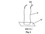
図1はまた、2つの一般的なタイプの縫合を示す。左手側では、縫合糸6は、経弁輪空間10または弁輪下方(もしくはインフラアニュラー)空間12にて、管壁に供給され得る。縫合糸6の終端は、綿撒糸16の後ろの縫合糸16にて、結び目18により、綿撒糸16に固定してよい。図2に示すように、縫合アセンブリは、共通の長さの縫合糸6で取り付けられた2つの曲がったニードル400から成る。一般的に、綿撒糸16は縫合糸6の上に予め取り付けられる。綿撒糸16は、管壁に対して、縫合糸のループ6の終端を固定する。それから、縫合糸6は、管壁を通過するように送り込まれて、弁輪上方空間8にて管壁から出る。外科医は、縫合リング14に縫合糸6を通過させて、結び目18を縫合リング14の後ろで結んで、縫合リング14を管壁に固定する。 FIG. 1 also shows two common types of suturing. On the left hand side, the
図1の右手側にて、縫合糸6は弁輪上方空間8にて管壁内に送り込まれる。それから、縫合糸6は、綿撒糸16に取り付けられて、図1の左手側の縫合に関して説明したように供給される。管の視界はしばしば、弁輪上方空間または経弁輪空間10からなので、この方法は、縫合糸6の管壁内への最初の挿入に関して、より良好な視界を、医療専門家に与える。 On the right hand side in FIG. 1, the
図3は、縫合糸6のマットレス・ステッチの拡大図である。縫合糸6の2つの端部は、別々に綿撒糸16の同じ側を経由するように送られる。それから、縫合糸6の両方の端部は、経弁輪空間10または弁輪下方空間12にて、管壁内に送られる。綿撒糸16は、縫合糸6を管壁に対して締める。それから、縫合糸6の両端は管壁と経由して送られ、弁輪上方空間8で管壁から出ていく。それから、縫合糸6の両端は、縫合リング14を通過する。それから、縫合糸6の端部は、互いに、縫合リング14の後ろで、結び目18で結ばれ、縫合リング14を管壁に固定する。 FIG. 3 is an enlarged view of the mattress stitch of the
弁置換処置の間、患者は心肺バイパスの状態にある。心肺バイパスは、患者の酸素レベルを減らし、非生理学的な血流力学を生成する。患者がより長い間、心肺バイパス状態にあると、永久的な健康上のダメージを含む、合併症のリスクがより大きくなる。既存の縫合技術は、バイパスの時間を延ばし、心肺バイパスに起因する健康上のリスクを増大させる。さらにまた、同じ医療専門家であっても、結び目を作る直前の縫合糸のプレテンショニング(または予め加えられる張力)を一定に維持することは難しいので、縫合により生じる固定力は実質的に変化する。 During the valve replacement procedure, the patient is in cardiopulmonary bypass. Cardiopulmonary bypass reduces the patient's oxygen level and creates non-physiological hemodynamics. The longer the patient is in cardiopulmonary bypass, the greater the risk of complications, including permanent health damage. Existing suturing techniques extend the time of bypass and increase the health risks resulting from cardiopulmonary bypass. Furthermore, even with the same medical professional, it is difficult to keep the pretensioning (or pre-tension) of the suture just before tying the knot constant, so the fixation force produced by the suturing varies substantially. .
弁プロテーゼを、周囲の組織または第2のプロテーゼであり得る第1の塊に固定するのに必要な時間を最小限にすることが、固定デバイスに関して求められている。また、既存のデバイスのユーザーが熟知している技術を使用する、固定デバイスもまた求められている。さらにまた、既存の縫合デバイスおよび縫合方法を補足し、固定時間を減らすデバイスもまた求められている。また、弁輪下方空間の視認、または弁輪下方空間への縫合アクセスを必要としない、固定デバイスも求められている。一定の固定力を与え得る固定デバイスを提供する必要もまた存する。バイパス処置の時間を短くでき、付随する健康上のリスクを最小限にし得る技術もまた、要求されている。 There is a need for an anchoring device to minimize the time required to anchor the valve prosthesis to the first mass, which can be the surrounding tissue or the second prosthesis. There is also a need for fixed devices that use techniques familiar to users of existing devices. There is also a need for devices that complement existing suturing devices and methods and reduce fixation time. There is also a need for a fixation device that does not require viewing the annulus lower space or stitching access to the annulus lower space. There also exists a need to provide a fixation device that can provide a constant fixation force. There is also a need for a technique that can shorten the time of the bypass procedure and minimize the associated health risks.
発明の概要
心臓弁デバイスが開示される。心臓弁はガスケットボディおよびガスケット・ボディの半径方向の外側サイド(または外側面)に配置されたレセプタクル(または容器)を有する。レセプタクルは、例えば、開口(またはフェネストレーション;fenestration)(例えば、窓、ギャップ、ポート、穴、溝穴)、缶(または容器)、ワイヤーフレーム、中空チャンネル、コレット(または玉受け)、プレート、グロメット(またはハト目)、ガイドブロック(もしくは滑り金)、スライドロッド、内側および外側の壁または壁部分を有するガイドブロックおよびスライドロッド、高摩擦チャンネル、カムの間の通路、他の相補的な(または相補形の、もしくは補足)固定デバイスもしくは相補的なアッタチメント、デバイスまたは他の適当な構造体、あるいはそれらの組み合わせであり得る。レセプタクルは、アタッチメントまたは固定デバイスを収容するように構成される。アタッチメントデバイスは、結節のないものであり得、レセプタクルは摩擦ロックを有し得る。摩擦ロックは、摩擦および/または締まり嵌めを用いて、レセプタクルを、アタッチメントデバイス(例えば、レセプタクル内の障害物またはプラグ)に固定して取り付けることができる。レセプタクルは、第1のカムを有してよく、第1のカムは回転可能にガスケットボディに取り付けることができる。レセプタクルは、フランジに存在することができる。フランジは、ガスケットボディの一部であってよく、あるいはレセプタクルは、ガスケットボディから独立しているが、ガスケットボディに取り付けられたものであってよい。SUMMARY OF THE INVENTION A heart valve device is disclosed. The heart valve has a gasket body and a receptacle (or container) disposed on the radially outer side (or outer surface) of the gasket body. The receptacle can be, for example, an opening (or fenestration) (eg, window, gap, port, hole, slot), can (or container), wire frame, hollow channel, collet (or ball holder), plate, Grommets (or eyelets), guide blocks (or slides), slide rods, guide blocks and slide rods with inner and outer walls or wall sections, high friction channels, passages between cams, other complementary ( Or a complementary or complementary) fixation device or complementary attachment, device or other suitable structure, or a combination thereof. The receptacle is configured to accommodate an attachment or fixation device. The attachment device can be free of nodules and the receptacle can have a friction lock. The friction lock can use a friction and / or interference fit to securely attach the receptacle to an attachment device (eg, an obstruction or plug in the receptacle). The receptacle may have a first cam that can be rotatably attached to the gasket body. The receptacle can be on the flange. The flange may be part of the gasket body or the receptacle may be independent of the gasket body but attached to the gasket body.
レセプタクルは、シリンダー内に形成することができる。シリンダーは、クリンプ可能な(または折り曲げ可能な、もしくは押し合わせることが可能な)シリンダーであり得る。シリンダーは、ガスケットボディに、固定して取り付けることができ、あるいは回転可能に取り付けることができる。シリンダーは、側壁ポートまたはスリットを有し得る。 The receptacle can be formed in a cylinder. The cylinder may be a crimpable (or foldable or pressable) cylinder. The cylinder can be fixedly attached to the gasket body or can be rotatably attached. The cylinder may have a side wall port or slit.
心臓弁を第1の塊に接続するアタッチメントデバイスもまた、開示される。アタッチメントデバイスは、ベース、第1の接続突起、および第2の接続突起を有する。ベースは、第1サイド、第2サイド、および折り曲げ可能なジョイントを有する。第1の接続突起は、第1のアタッチメントエリアにて、ベースの第1サイドに固定して取り付けられる。第2の接続突起は、第2のアタッチメントエリアにて、ベースの第1サイドに固定して取り付けられる。 An attachment device that connects the heart valve to the first mass is also disclosed. The attachment device has a base, a first connection protrusion, and a second connection protrusion. The base has a first side, a second side, and a foldable joint. The first connection protrusion is fixedly attached to the first side of the base in the first attachment area. The second connection protrusion is fixedly attached to the first side of the base in the second attachment area.
第1の接続突起は、湾曲していてよい。第2の接続突起は、湾曲していてよい。折り曲げ可能なジョイントは、第1のアタッチメントエリアと第2のアタッチメントエリアとの間にあってよい。折り曲げ可能なジョイントは、ベースにおける折り目であってよい。 The first connection protrusion may be curved. The second connection protrusion may be curved. The bendable joint may be between the first attachment area and the second attachment area. The foldable joint may be a fold in the base.
心臓弁を第1の塊に接続するための別のアタッチメントデバイスもまた開示される。このアタッチメントデバイスは、ベースおよび湾曲したシャフトを有する。ベースは球およびベース径を有する。湾曲したシャフトは、第1の端部、第2の端部、およびシャフト径を有する。第1の端部は鋭利にされており、第2の端部はベースに取り付けられている。ベース径は、シャフト径よりも大きい。 Another attachment device for connecting the heart valve to the first mass is also disclosed. The attachment device has a base and a curved shaft. The base has a sphere and a base diameter. The curved shaft has a first end, a second end, and a shaft diameter. The first end is sharpened and the second end is attached to the base. The base diameter is larger than the shaft diameter.
心臓弁もまた開示される。心臓弁は、ガスケットボディ、第1のタブ、および第2のタブを有する。ガスケットボディは、上側表面および下側表面を有する。第1のタブは、折り曲げ可能に、上側表面に取り付けられる。第2のタブは、折り曲げ可能に、下側表面に取り付けられる。第1のタブは、曲げられた位置に、予め展開させることができる。 A heart valve is also disclosed. The heart valve has a gasket body, a first tab, and a second tab. The gasket body has an upper surface and a lower surface. The first tab is foldably attached to the upper surface. The second tab is foldably attached to the lower surface. The first tab can be pre-deployed in a bent position.
別の心臓弁が開示される。この心臓弁は、ガスケットボディ、および第1のタブを有する。ガスケットボディは、上側表面、下側表面、および上側表面と下側表面との間の中間領域を有する。第1のタブは、折り曲げ可能に、中間領域に取り付けられる。 Another heart valve is disclosed. The heart valve has a gasket body and a first tab. The gasket body has an upper surface, a lower surface, and an intermediate region between the upper and lower surfaces. The first tab is foldably attached to the intermediate region.
別の開示される要旨は、開示したデバイスを使用して、当業者に公知のデバイス(例えば、ステント、グラフト(graft)、ステントグラフト、心臓弁、弁輪形成リング、およびそれらの組み合わせ)を取り付けることである。 Another disclosed subject matter uses the disclosed devices to attach devices known to those skilled in the art (eg, stents, grafts, stent grafts, heart valves, annuloplasty rings, and combinations thereof). It is.
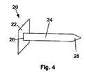
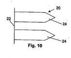
図4は、固定デバイス20のアタッチメント、例えば、無頭釘(例えば、シングルブラッド、ダブルブラッド(または二倍もしくは二重無頭釘)、クアドルプルブラッド(または四倍もしくは四重無頭釘))、鋲、スパイク、ステープル、バーブ(または棘)、フック、またはそれらの任意の組み合わせである。固定デバイス20は、ベース22およびコネクタを有してよい。コネクタは、例えば、接続突起24である。ベース22は、中実(もしくは立方体)であってよく、および/または実質的に球形であってよい。ベース22は、2002年12月20日に出願された米国特許出願10/327,821に説明されているように、半径方向に膨張(または拡張)可能な部分を有していてよい。この出願は引用によりその全体が本明細書に組み込まれる。突起24は、第1の端部26と、第2の端部28とを有し得る。第1の端部26は、ベース22に固定されて取り付けられてよい。第2の端部28は、鋭利にする、または尖らせることができる。 FIG. 4 shows attachments of the
固定デバイス20は、プロテーゼを第1の塊に取り付けるために使用し得る。プロテーゼは、例えば、ステント、グラフト、ステントグラフト、心臓弁、弁輪形成リング、自家
移植片、同種移植片、異種移植片、またはそれらの組み合わせであり得る。第1の塊は、例えば、管、弁、臓器(例えば、腸、心臓、皮膚、肝臓、腎臓)、またはそれらの組み合わせのような組織であり得る。The
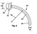
図5は、湾曲し得る突起24を有する固定デバイス20を示す。突起24は、中心線30を有し得る。中心線30は、曲率半径32を有し得る。ベース22はベース径(または差し渡し)34を有し得る。ベース22は、実質的に平らな正方形、矩形、円形もしくは楕円形、または球形、円筒形、または立方体であるように構成することができる。突起24は、平坦、四角形、または円筒形になるように構成することができ、また、まっすぐにする、湾曲させる、あるいは傾斜させることができる。突起24は、突起径36を有し得る。固定デバイス20は、綿撒糸16を有してよい。綿撒糸16は、ベース22の付近に又はベース22に当てて、スライド可能に又は固定されて、突起24に取り付けられている。綿撒糸16は、ベース22に固定されて又は回転可能に取り付けてよい。 FIG. 5 shows a
固定デバイス20は、ステンレス鋼合金、ニッケルチタン合金(例えば、ニチノール)、コバルトクロム合金(例えば、エルジロイ(ELGILOY)(登録商標) Elgin Specialty Metals、エルジン、イリノイ州提供;CONICHROME(登録商標) Carpenter Metals Corp.、ワイオミッシング、ペンシルベニア州提供)、ポリマー、例えば、ポリエステル(例えば、DACRON(登録商標)、E. I. Du Pont de Nemours and Company、ウィルミントン、デラウェア州提供)、ポリプロピレン、ポリテトラフルオロエチレン(PTFE)、発泡PTFE(ePTFE)、ポリエーテルエーテルケトン(PEEK)、ナイロン、ポリエーテルブロックコポリアミドポリマー(例えば、PEBAX(登録商標) ATOFINA、パリ、フランス提供)、脂肪族ポリエーテルポリウレタン(例えば、TECOFLEX(登録商標) Thermedics Polymer Products、ウィルミントン、マサチューセッツ州提供)、ポリ塩化ビニル(PVC)、ポリウレタン、熱可塑性プラスチック、フッ化エチレンプロピレン(FEP)、押出しコラーゲン、シリコーン、放射線不透過性材料、またはそれらの組み合わせから形成され得る。放射線不透過性材料の例は、硫酸バリウム、チタン、ステンレス鋼、ニッケルチタン合金、タンタル、および金である。 Fixing
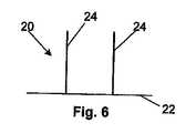
固定デバイス20は、複数のコネクタ、例えば、図6〜11に示すように、複数の突起24を有してよい。複数の突起24は、互いに整列させてよい。突起24は、変形可能であってよく、あるいは変形できないものであってよい。固定デバイス20は、4つの突起24を有し得る。ここで2つの突起24はジョイントの各々の側に位置する。ジョイント24は、例えば、ベース22における、真っ直ぐな折り曲げ可能な折り目38、ベース22の薄くされた及び/またはアニールされた部分、ベース22におけるメカニカルヒンジ、またはそれらの組み合わせである。突起24は、図7および図9に示すように、ベース22の外側エッジに取り付けられていてよい。図7および図9の突起24は、ベース22と同じピースの材料から切り取ることができ、所定の位置へ変形可能に折り畳むことができる。突起24は、図6および図8に示すように、ベース22の外側エッジから離れたところで、ベース22に取り付けることができる。 The
ベース22は、折り目38から遠ざかる方向に、突起24を越えて延びて、保持パッド402を形成し得る。ベース22においては、アラインメント(または位置合わせ)穴404を、例えば、ベース22の中央に、折り目38に沿って形成して、固定デバイス22と展開ツールまたはアプリケータアセンブリと整列させることができる。 The base 22 may extend beyond the
図10は、実質的にまっすぐであり得る突起24を示す。図11は、鎌の形状、または偃月刀の形状を実質的に有し得る、突起24を示す。ベース22は、ベース高さ406を有し得る。ベース高さ406は、約1.27mm(0.050インチ)〜約12.7mm(0.500インチ)であり得、例えば、約3.18mm(0.125インチ)であり得る。 FIG. 10 shows a
プロテーゼ
図12は、種々の開口部、レセプタクル、または窓(もしくはウィンドウ)42を有し得る、例えばリングである心臓弁ガスケットボディ40を示す。窓42は、例えば、正方形、矩形、卵形または円として構成することができる。窓42は、すべて同じ形状を有することができ、あるいは窓42は異なる形状であり得る。ガスケットボディ40は、患者の弁輪(または環状部)の形状に合うようないずれの形状構成であってよく、その形状には、変則的なものに合うような形状(例えば、小葉状の弁輪)が含まれる。ガスケットボディ40は、例えば、円形、卵形、楕円形、二葉状、または三葉状であってよい。ガスケットボディ40は、2002年12月30日に提出された米国特許出願10/327,821で説明されているデバイスの任意の特徴を含み得る。ガスケットボディ40は、固定デバイス20に関して先に挙げた材料、またはそれらの組み合わせのいずれによっても、構成されてよい。ガスケットボディ40は、可撓性および/または剛性を有するものであってよい。ガスケットボディ40は、ガスケット高さ408およびガスケット径410を有してよい。ガスケット高さ408は、おおよそ、冠状動脈の開口部と、僧帽弁前尖の付着部および心室内の隔壁の最も高い部分により規定される面における最も近いポイントとの間の長さから、約12.7mm(0.500インチ)までであり得、例えば、5.08mm(0.200インチ)であってよい。ガスケット径410は、約10mm(0.39インチ)〜約50mm(2.0インチ)であり得、より狭くは約30mm(1.2インチ)〜約40mm(1.6インチ)であり得る。Prosthesis FIG. 12 shows a heart
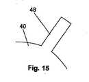
図13は、トップエッジまたはサイド44、およびボトムエッジまたはサイド46を有し得る、ガスケットボディ40を示す。歯、プロング(または尖った先)、またはタブ48を、トップエッジ44および/またはボトムエッジ46に取り付けてよい。タブ48は、タブ長50を有し得る。タブ長50は、他の臓器または組織(例えば、心室)を損傷することなく、弁輪組織に機械的に係合するように、十分な寸法を有するようにし得る。 FIG. 13 shows a
図14は、トップエッジ44に取り付けられた、予め展開されたタブ48を有し得る、ガスケットボディ40の断面A−Aを示す。トップエッジ44に取り付けられたタブ48は、ガスケットボディ40の壁52から、実質的に垂直に延びてよい。トップエッジ44に取り付けられたタブ48は、半径方向で外側に及び/または下側に向いていてよい。ボトムエッジ46に取り付けられたタブ48は、ガスケットボディ40の壁52から、実質的に平行に延びてよい。ボトムエッジ46に取り付けられるタブ48は、下向きにまっすぐに向いていてよく、あるいは半径方向で内向きに又は外向きに傾斜をつけられてよい。 FIG. 14 shows a cross-section AA of the
図15は、矩形の形状構成を有して得るタブ48を示す。図16は、丸み帯びた形状構成を有し得るタブ48を示す。図17は、鋭利なスパイク状の形状構成を有し得るタブ48を示す。図18は、分岐したV形状またはY形状の構成を有し得るタブ48を示す。図19は、小孔(もしくはポア)または穴(もしくはホール)54を有し得るタブ48を示す。図20は、微小係合デバイス、例えば、鋲、スパイク、フックおよび/またはバーブ(もしくは棘)56を有し得るタブ48を示す。前述のタブの形状構成およびエレメントは組み合わせて使用することができる。 FIG. 15 shows a
図21は、トップエッジ44とボトムエッジ46との間でタブ48を有し得るガスケットボディ40を示す。タブ48は、ガスケットボディ40の壁52の実質的に変形可能なセクションであってよい。 FIG. 21 shows a
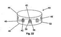
図22は、タブ48のサイドから延びるサイドウィング58を備えたタブ48を有し得る、ガスケットボディ40を示す。タブ48は、トップエッジ44とボトムエッジ46との間にあってよく、ならびに/またはタブ48はトップエッジ44にあってよく、ならびに/またはタブはボトムエッジ46にあってよい。サイドウィング58は、ガスケットボディ40の壁52の実質的に変形可能なセクションであっておい。タブ48の幾つか又はすべてが、その中のレセプタクルまたは窓42を有していてよく、それにより、タブ48を変形可能なレセプタクルまたは窓42として機能させることができる。あるいは、タブ48いずれも、その中にレセプタクルまたは窓42を有していなくてもよい。 FIG. 22 shows a
図23は、協同的な又は相補的な(または相補形の)固定(またはアタッチメント)デバイスを有し得る、ガスケットボディ40を示す。そのようなデバイスは、例えば、摩擦ロックまたは機械的な締まり嵌めデバイスのようなレセプタクルであり、例えば、縫合糸6(縫合糸6はここでは縫合糸6および他の類似のアタッチメントメカニズムを指す)である固定デバイスを収容するような形状構成を有する。協同的または相補的な固定デバイスは、固定デバイスに係合し、かつ固定デバイスがプロテーゼ(例えば、ガスケットボディ)に固定され又はプロテーゼに付着するのを補助する、デバイスまたは形状構成である。縫合糸6は、2−0縫合糸、0縫合糸、当業者に公知の別の縫合糸、またはそれらの組み合わせである。レセプタクルは独立していてよく、それは、各レセプタクルが直接的には他のレセプタクルと接続されていないことを意味する。レセプタクルは、例えば、変形可能なシリンダーのような缶(または容器)60であり得る(「缶」60は、本明細書を通じて、シリンダーまたはシリンダーでないものを指す)。缶60は、アニールしてよく、あるいは、缶60をより容易に変形し得るものとするように処理してよい。缶60は、缶径412および缶高さ414有し得る。缶内径412は約0.838mm(0.033インチ)から約2.54mm(0.100インチ)までであってよく、例えば、約0.838mm(0.033インチ)であってよい。缶外径412は、約1.3mm(0.050インチ)から、約3.18mm(0.125インチ)までであってよく、例えば、約1.3mm(0.050インチ)であってよい。缶高さ414は、約1.3mm(0.050インチ)から約6.35mm(0.250インチ)までであってよく、例えば、約3.18mm(0.125インチ)であってよい。 FIG. 23 illustrates a
各缶60は、中空のチャンネル62を有し得る。中空のチャンネル62は、缶60の内側および/または外側に位置してよい。中空のチャンネル62は、縫合糸6のための通路(またはパス)であり得る。相補的な固定デバイスは、ガスケットボディ40の壁52の内部に、(図22に示すように)半径方向の外周側に、または半径方向の内周側に、取り付けることができる。相補的な固定デバイスおよびそれに付随するパーツは、固定デバイス20に関して先に挙げたのと同じ材料のいずれで作製してもよい。 Each can 60 may have a
ガスケットボディ40は、ガスケットボディ40の中心を通る、ガスケット長手方向軸534を有し得る。相補的なアタッチメントデバイスの内側半径536は、ガスケット長手方向軸534から、缶60のガスケット長手方向軸534から最も近い部分までで、測定され得る。相補的なアタッチメントデバイスの外側半径538は、ガスケット長手方向軸534から、缶60のガスケット長手方向軸534から最も遠い部分までで、測定され得る。ガスケットボディの半径540は、ガスケット長手方向軸534から、ガスケットボディ40に至るまで、延びることができる。ガスケットボディの内側および外側半径(図示せず)は、ガスケットボディの半径540から、ガスケットボディ40のガスケット長手方向軸534に最も近い部分および当該軸534から最も遠い部分までで、それぞれ測定され得る。 The
相補的なアタッチメントデバイスの外側半径538が、ガスケットボディの外側半径540よりも大きい場合、相補的なアタッチメントデバイスの内側半径536は、ガスケットボディの外側半径540よりも大きくてよく、当該半径540と略等しくてよく、または当該半径540よりも小さくてよい。あるいは、相補的なアタッチメントデバイスの内側半径536は、ガスケットボディの内側半径540よりも大きくてよく、当該半径540に略等しくてよく、あるいは当該半径540よりも小さくてよい。相補的なアタッチメントデバイスの外側半径538は、ガスケットボディの外側半径540よりも小さい場合(缶60がガスケットボディ40の内側に位置する半径上にある場合)、相補的なアタッチメントデバイスの内側半径536は、ガスケットの外側半径540よりも大きくてよく、当該半径540と略等しくてよく、または当該半径540よりも小さくてよく、あるいは、相補的なアタッチメントデバイスの内側半径は、ガスケットの内側半径よりも大きくてよく、当該半径540と略等しくてよく、または当該半径540よりも小さくてよい。 If the
図24は、フランジ64(例えば、柔軟なパッドである)を有し得る、図23のガスケットボディ40を示す。フランジ64は、部分的に及び/または完全に、ガスケットボディ40を円周方向で囲む。フランジ64は、中実であってよく、あるいは多孔質であってよい。フランジ64は、布帛であってよく、例えば、ポリエステル(例えば、DACRON(登録商標)、E. I. du Pont de Nemours and Company、ウィルミントン、デラウェア州提供)、ポリプロピレン、PTFE、ePTFE、ナイロン、押出しコラーゲン、シリコーン、またはそれらの組み合わせであってよい。フランジ64は、使用中、細胞成長のためのマトリックス(または母体)となり得る。フランジ64および/または本発明の他のいずれの部分も、当業者に公知の薬剤デリバリーマトリックスおよび/または治療薬および/もしくは診断薬で満たされていてよく、ならびに/あるいはそれで被覆されていてよい。これらの薬剤として、放射性物質;放射線不透過性物質;細胞発生剤;細胞毒性薬;細胞増殖抑制剤;血栓形成剤を挙げることができ、例えば、ポリウレタン、三酸化ビスマスと混合した酢酸セルロースポリマー、およびエチレンビニルアルコール;滑らかな親水性材料;燐光性コレン;抗炎症剤、例えば、非ステロイド性の抗炎症剤(NAIDs)、例えば、シクロオキシゲナーゼ−1(COX−1)阻害剤(例えば、アセチルサリチル酸、例えば、ASPIRIN(登録商標) バイエルAG、レーフェルクーゼン、ドイツ提供;イブプロフェン、例えば、ADVIL(登録商標) Wyeth、カレッジビル、ペンシルベニア州提供;インドメタシン;メフェナム酸)、COX−2阻害剤(例えば、VIOXX(登録商標) Merck&Co., Inc.、ホワイトハウステーション、ニュージャージー州提供;CELEBREX(登録商標) Pharmacia Corp.、ピーパック、ニュージャージー州提供;COX−1阻害剤);免疫抑制剤、例えば、シロリムス(RAPAMUNE(登録商標)、Wyeth、カレッジビル、ペンシルベニア州提供)、または炎症反応の経路内で早期に作用するマトリクス・メタロプロテイナーゼ(MMP)阻害剤(例えば、テトラサイクリンおよびテトラサイクリン誘導体)である。他の薬剤の例は、Waltonらの「腹部の大動脈瘤における、プロストグランジンE2合成の阻害(Inhibition of Prostoglandin E2 Syhthesis in Abdominal Aortic Aneurysms)」、Circulation、1999年7月6日、48−54頁;Tambiahら「実験的な大動脈炎症メディエータおよびクラミジア肺炎の誘発(Provocation of Experimental Aortic Inflammation Mediators and Chlamydia Pneumoniae)」、Brit. J. Surgery 88(7)、935−940頁;Franklinらの「テトラサイクリンの腹部大動脈瘤壁による取り込み、ならびに炎症および蛋白質分解に及ぼすその影響(Uptake of Tetracycline by Aortic Aneurysm Wall and Its Effect on Inflammation and Proteolysis)」、Brit. J. Surgery 86(6)、771−775頁;Xuらの「Sp1は低酸素症の管の内皮細胞においてシクロオキシゲナーゼ−2の発現を増加させる(Sp1 Increases Expression of Cyclooxygenase-2 in Hypoxic Vascular Endothelium)」、J. Biological Chemistry 275(32)、24583−24589頁;およびPyoらの「マトリックスメタロプロテナーゼ−9(ゼラチナーゼB)の標的遺伝子破壊は実験的な腹部大動脈瘤の成長を抑える(Targeted Gene Disruption of Matrix Metalloproteinase-9 (Gelatinase B) Suppressed Development of Experimental Abdominal Aortic Aneurysms)」、J. Clinical Investigation 105(11)、1641−1649頁において、提供されている。これらの文献は、引用により全体が本明細書に組み込まれる。FIG. 24 shows the
フランジ64は、円形、卵形、または正方形の断面を有し得る。フランジ64は壁52および/または缶60に取り付けることができる。フランジ64は、缶60の上方および/または下方にあってよい。フランジ64は、ガスケットボディ40、缶60または他のパーツにて露出した鋭利なエッジを被覆してよい。フランジ64は、ガスケットボディ40の外周を囲むことができ、および/またはガスケット40の外周を囲まない1または複数のセグメント(図示せず)であってよい。フランジ64は、管(またはカニューレ)が挿入された縫合糸ポート66を有してよい。当該ポート66は、缶60と整列させることができ、および/またはいずれの縫合糸ポートも缶60と整列させなくてもよい。缶60は部分的に又は完全にフランジ64の内部にあってよい。使用中、特定の缶60について、縫合糸を、縫合糸ポート60の中に通過させてよく、ならびに/またはフランジ64の中および/もしくはフランジ64の周囲を通過させてよい。 The
図25は、縫合リング14として構成されたフランジにより囲まれ得る、ガスケットボディ40を示す。縫合リング14は、中実または多孔質であってよい。縫合リング14は、布であってよく、また、フランジ64に関して先に挙げたいずれの材料で作製してもよい。縫合リング14は、使用中、細胞成長のためのマトリックスとなり得る。 FIG. 25 shows a
縫合リング14は、壁52および/または缶60に取り付けることができる。縫合リング14は、およそボトムエッジ46から、およそトップエッジ44に向かって、延在し得る。縫合リング14は、ガスケットボディ40、缶60、または他のパーツで、露出したエッジおよび/または金属をカバーし得る。縫合リング14は、(図25に示すように)ガスケットボディ40の外周を囲むことができ、および/またはガスケットボディ40の外周を囲まない1または複数のセグメント(図示せず)にあってよい。縫合リング14は、管(またはカニューレ)が挿入された縫合糸ポート66を有してよい。当該ポート66は、缶60と整列させることができ、および/またはいずれの縫合糸ポートも缶60と整列させなくてもよい。使用中、特定の缶60について、縫合糸を、アクセスもしくは縫合糸ポート60の中に通過させてよく、ならびに/または縫合糸リング14の中および/もしくは縫合糸リング14の周囲を通過させてよい。アクセスまたは縫合糸ポート66は、ガスケットボディ40を展開する前に、予め形成することができる。ガスケットボディ40は、縫合リング14を有してよく、また、缶60を有していなくてもよい。 The
縫合リング14は、フレア(もしくは広がった部分)またはスカート70を組み込んでいてよい。スカート70は、縫合リング14の外周(図示せず)を囲むことができ、または縫合リング14の外周を囲まない1または複数のセグメントにあってよい。スカート70は、縫合リング14から放射状に延びていてよい。スカート70は、ボトムエッジ46の付近に、又はボトムエッジ46に配置されてよい。
図26は、断面B−Bの一形態を示す。缶60は、縫合リング14内にあってよい。缶60は、トップエッジ44の付近に、又はトップエッジ44に配置されてよい。縫合糸ポート66は、同じ寸法のままであってよく、あるいは、縫合糸ポート66が缶60から離れていくにしたがって、広がってよい。縫合リング14は、縫合糸ポート66上で閉じていてよい。縫合リングは、縫合糸ポート66の隣に、グロメット、ボタンホール、またはガセット416を形成してよい。ガセット416は、自動閉鎖のものであってよい。縫合リング14は、補強材418を有してよく、補強材418はガセット416を取り囲んでよい。補強材は、ここで挙げた材料のいずれで形成してもよく、例えば、金属またはプラスチックリングで形成してよい。補強材418はまた、縫合リング14の材料を厚くした部分または付加的に密にした部分であってよい。 FIG. 26 shows one mode of a cross section BB. The
図27は、断面B−Bの一形態を示す。縫合リング14は、縫合リング高さ420を有する。缶高さ414は、縫合リング高さ420よりも小さいか、それと等しいか、あるいはそれよりも大きい。縫合リング高さ420は、約1.3mm(0.050インチ)〜約6.35mm(0.250インチ)であってよく、例えば約3.18mm(0.125インチ)であってよく、例えば、約5.08mm(0.200インチ)であってもよく、さらに別の例では、約6.35mm(0.250インチ)であってよい。缶60は、ボトムエッジ46の付近、又はボトムエッジ46に配置されてよい。縫合糸ポート66の断面の寸法は、縫合糸ポート66が缶60から離れていくにしたがって、広がっていてよく、減少していてよく、あるいは同じままであってよい。缶60は、アタッチメントプロング71を有してよい。缶60は、アタッチメントプロング71にて、縫合糸リング14に取り付けられてよく、あるいは、当該分野で公知の他の取り付け方法、例えば、当該分野で公知の縫合方法で取り付けられてよい。スカート70の外側半径または縫合リング14の残部は、所望のように剛性を変化させるために、形作られ、所定の大きさにされ、被覆され、又は処理され、あるいはそれらを組み合わせて加工される。例えば、スカート70は、それに形成された、レリーフの(または起伏を有する)溝を有してよい。レリーフの溝422は、半円形、方形、半卵形、星形、またはそれらの組み合わせであってよい。 FIG. 27 shows one mode of a cross section BB. The
縫合リング14は、ガスケットボディ40から缶60を吊していてよい。缶60は、少ない抵抗で、回転して、ガスケットボディ40から移動してよく、それにより、壁52により弁輪(または環状部)が不必要に変形することなく、ガスケットボディ40を第1の塊にぴったりと固定させる。 The
図28は、縫合糸6、スネアまたは固定のための他のエレメントを収容するようになっている缶60を示す。缶60は、缶60内でまがりくねった通路を有し得る中空のチャンネル62を規定する、受動的な(または動かない)内部障害物、例えば、ずらして配置された内部障害物72を有してよい。内部障害物72は、缶60からの摩擦と比較して、縫合糸6に対して大きい摩擦を提供し得るポリマーで構成してよい。内部障害物72は、他の任意のエレメントに関して挙げた材料のいずれで形成してもよく、あるいは任意のそれらの組み合わせで形成してよい。缶60は、固定して又は回転可能に軸74に取り付けてよい。 FIG. 28 shows a
図29は、整列した内部障害物72を有し得る缶60を示す。缶60は、フレーム76に固定して又は回転可能に取り付けられてよい。内部障害物72は、缶60が押しつぶされるときに、つぶれる又は押しつぶされるように構成してよく、例えば、内部障害物72は中空であってよい。 FIG. 29 shows a
図30は、缶60、およびシールするように缶の端部80に嵌る寸法にされた、空間占有弾性エレメント(例えば、プラグ78)を示す。空間占有(または空間を塞ぐ)エレメントは、例えば、エラストマーおよび/または他の任意のエレメントに関して挙げた他の任意の材料もしくはその組み合わせで、構成することができる。プラグ78は、取り外し可能なように、係合要素(例えば、分離可能な(または独立した、もしくは簡単に取り壊し可能な)ライン(もしくは紐)82)に取り付けることができる。分離可能なライン82は、缶60内で(矢印で示すように)引っ張られて、缶の端部80にてプラグ78に係合し、プラグ78を固定する。分離可能なライン82は、最大張力を越えたときに、プラグ78から分離されるように構成してよい。プラグ78は、缶の他方の端部80に係合させて、固定させてよい。2つの空間占有エレメントを使用してよく、缶の各端部80について、1つの空間占有エレメントが充てられる。空間占有エレメントは、縫合糸6が空間占有エレメント内で及び/又はその付近で、展開される及び/又は引っ張られるときに、缶の端部80内で、固定され、係合し、固定し、また、自己係合するものであってよい。 FIG. 30 shows a
図31は、缶60、および缶の端部80に嵌るような寸法にされたプラグ78を示す。プラグは、プラグ高さ84を有し得る。プラグ高さ84は、約1.3mm(0.050インチ)〜約6.35mm(0.250インチ)であってよく、例えば約3.18mm(0.125インチ)であってよい。プラグ高さ84は、缶の高さ414に実質的に等しくてよく、あるいは缶60に対して縫合糸6を十分に係合させる寸法を有してよい。缶60内へプラグ78を押す挿入力は、缶60内でプラグ78を固定するのに略十分である力から、ガスケットボディ40を埋め込みサイトに固定する保持力に略等しい力までであってよい。例えば、缶の内側半径412が約8.4mm(0.33インチ)である缶60に関しては、約0.64mm(0.025インチ)の直径を有するプラグ78の挿入力は、約11N(2.5ポンド)であってよい。別の例において、缶の内側半径412が約8.4mm(0.33インチ)である缶60に関しては、約0.66mm(0.026インチ)の直径を有するプラグ78の挿入力は、約19N(4.3ポンド)であってよい。 FIG. 31 shows a
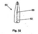
図32は、閉じたままであるようにバイアスが欠けられた、弾力性を有する缶60を示す。缶60は、弾性材料、例えば、ポリマー、ここで挙げた他の任意の材料、またはそれらの任意の組み合わせで形成してよい。缶60は、缶60の側部にて、溝穴88を有してよい。 FIG. 32 shows a
図33は、能動的な(または動きを生じる)内部障害物、例えば、拡張可能な障害物100を有し得る缶60を示す。拡張可能な障害物100は、例えば、変形可能に拡張可能である(例えば、バルーン膨張可能な)又は弾力的に拡張可能な(例えば、自己膨張可能な)、空間占有エレメント、例えば、変形可能なシリンダー、ステント、またはバルーンであってよい。中空のチャンネル62は、拡張可能な障害物100と缶60との間にあってよい。中空のチャネル62は、縫合糸6を通過させる、環状の空間を形成してよい。缶60は、長手方向の軸424を有してよい。拡張可能な障害物100または缶60は、長手方向に保持する部材426を、一方または両方の端部に有してよい。当該部材426は、缶の長手方向の軸42に対して垂直に延び、拡張可能な障害物100を缶60に対して長手方向において拘束する。 FIG. 33 illustrates a
缶60はまた、半径方向で圧縮可能であってよく、障害物100は、半径方向で圧縮できないものであってよい。使用中、缶60は障害物100上に圧縮される。 The
図34は、コレット102、および広がり(又はスプレイド;splayed)端部104を有してよい缶60を示す。コレット102は、広がり端部104を収容する寸法を有するようにされた缶ポート106を有してよい。缶60は、缶本体108、および広がり端部104にて付加部分110を有してよい。付加部分110は、弾性的に又は変形可能に、缶本体108に取り付けてよい。付加部分110は、付加部分110が缶本体108から離れるにしたがって、半径方向において内側にバイアスをかけてよい。使用中、缶60は、矢印112で示すように、コレット102に向けて移動させることができ、および/または、矢印114で示すように、コレット102は缶60に向かって移動させることができる。広がり端部104は缶ポート106内に移動させてよく、また、矢印116で示すように、広がり端部104が半径方向に収縮させられて、所望の位置に至るまで、缶ポート106内を移動させ続けてよい。 FIG. 34 shows a
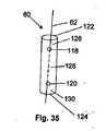
図35は、第1の開口または窓118および第2の開口または窓120を有し得る、缶60を示す。缶60は、第1の窓118により近い第1の缶端部122を有してよい。缶60は、第2の窓120により近い第2の缶端部124を有してよい。缶60は、第1の缶端部122と第1の窓118との間で、第1の缶セグメント126を有してよい。缶60は、第1の窓118と第2の窓120との間で、第2の缶セグメント128を有してよい。缶60は、第2の窓120と第2の缶端部124との間で、第3の缶セグメント130を有してよい。 FIG. 35 shows a
中空のチャンネル62は、第1の缶セグメント126の領域において、缶60の半径の外側にあってよい。中空のチャンネル62は、第1の缶ウィンドウを通過してよい。中空のチャンネル62は、第2の缶セグメント128の領域において、缶60の半径の内側にあってよい。中空のチャンネル62は、第2のウィンドウ120を通過してよい。中空のチャンネル62は、第3の缶セグメント130の領域において、缶60の半径の外側にあってよい。 The
中空のチャンネル62は、第1、第2および第3の缶セグメント126、128および130に関して、缶60の半径の内部および/または外部を、いずれの組み合わせで通過してよい。中空のチャンネル62が1つの缶セグメントから隣の缶セグメントに進行するとき、中空のチャンネル62は開口または窓を通過する必要はない。 The
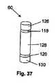
第1および第2の窓118および120は、図35に示すような円形、図36に示すような矩形、卵形、正方形、またはそれらの組み合わせであってよい。窓はまた、図37に示すように、約360°までの角度幅を有してよい。窓118および/または120の角度幅が360°であるとき、缶のセグメント126、128および130は完全に互いから分離され得る。 The first and
図38は、実質的に第2の缶セグメント128と実質的に整列していなくてよい(または一直線上になくてよい)、第1の缶セグメント126および第3の缶セグメント130を有し得る、缶60を示す。例えば、第1および第3の缶セグメント126および130は、実質的に平坦であってよい。第2の缶セグメント128は、湾曲していてよく、例えば、半円形状であってよい。 FIG. 38 may have a
第1の方向132は、第2の方向と実質的に反対であってよい。中空のチャンネル62は、第1の缶セグメント126の第1の方向の側を通過してよい。中空のチャンネル62は、第1の窓118を通過してよい。中空のチャンネル62は、第2の缶セグメント128の第2の方向の側を通過してよい。中空のチャンネル62は、第2の窓120を通過してよい。中空のチャンネル62は、第3の缶セグメント130の第1の方向の側を通過してよい。 The
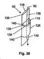
図39および図40は、図38に示す缶60の形状に類似する形状に押しつぶされたシリンダーであってよい缶60を示す。缶60は、フロンパネル136およびリアパネル138を有してよい。缶60は、缶セグメント126、128および130の間で、ギャップ140を有してよい。ギャップ140は、隣り合う缶セグメント126、128または130に隣る、パネル136および/または138一部を除去することにより、形成し得る。例えば、第1および/または第3の缶セグメント126および/または130におけるフロントパネル136の一部を除去してよく、ならびに/あるいは第2の缶セグメント128におけるリアパネル138の一部または複数の部分を除去してよい。使用中、第2の缶セグメント128が第1セグメント126および/または第3セグメント130と実質的に平行である位置に押し付けられると、ギャップ140は、中空チャンネル62を通過する縫合糸6に加わる剪断力を減らし得る。 39 and 40 show a
図41は、1または複数のワイヤで形成され得る缶60を示す。1または複数のワイヤは、変形可能であってよく、あるいは弾性を有してよい。缶60は、第1のループ142、第2のループ144およびシャーシ146を有してよい。第1のループ142は、シャーシ146に固定して取り付けてよい。第2のループ144は、シャーシ146に固定して取り付けてよい。追加のループをシャーシ146に取り付けてよい。シャーシ146は、第1のループ142と第2のループ144との間の、単一のワイヤであってよい。 FIG. 41 shows a
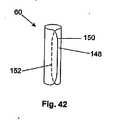
図42は、プレート148から形成され得る缶60を示す。プレート148は、例えば、巻き付けることにより、あるいは加熱成形または冷間成形により、実質的に円筒形に形成してよい。プレートの第1端部150は、プレートの第2端部152と重なってよい。 FIG. 42 shows a
図43は、第1のガスケット層428と第2のガスケット層430の積層体で形成され得るガスケットボディ40を示す。第1および第2のガスケット層428および430は、固定して又はスライド可能に、スライドロッド432に取り付けられ、固定して第1のガイドブロック434および第2のガイドブロック436に取り付けられる。第1および第2のガイドブロック434および436は、ボトムエッジ46の隣にあってよい。固定デバイス20は、長いスライドポート438を有してよい。固定デバイス20は、スライドポート438にてスライドロッド432にスライド可能に取り付けてよい。固定デバイス20の鋭利にされた先端440は、相補的な固定デバイス(例えば、第1のガイドブロック434と第2のガイドブロック436との間に形成されたレセプタクル)において、スライド可能に配置してよい。固定デバイス20は、スライドロッド432上で制限的にスライド可能であるために、固定デバイス20が、ガスケットボディ40から、完全に逃げるまたは外れることが防止され得る。固定デバイス20は、ガスケットボディ40が展開する前に、ガスケットボディ40に取り付けられてよく、また、第1の塊に関して固定デバイス20の状態および/または配置に応じて、組織内で選択的に作動させられ、または展開させてよい。 FIG. 43 shows a
図44は、図43に示す固定デバイス20であって、互いに隣り合って配置された2つの固定デバイスを示す。固定デバイス20は、互いに向かい合うように、相対する方向に向けられており、それにより、2つの固定デバイス20は展開後、図示するように重なる及び/または隣り合う配置となる。 FIG. 44 shows two fixing
図45は、第2のガスケット層430の無い、図43の構成を示す。スライドロッド432は、第1の端部にて、固定して又は回転可能に、ガスケットボディ40に取り付けられてよい。スライドロッド432は、固定して又は回転可能に、第2の端部にて、半径方向付けエレメント442に取り付けられてよい。半径方向付けエレメント442は、円形であり、スライドロッド432よりも大きい直径を有してよい。 FIG. 45 shows the configuration of FIG. 43 without the
図46〜図48は、半径方向付けエレメント要素442を示している。図46は、卵形、矩形または細長い形状であってよい半径方向付けエレメント442を示す。図47は、薄くて、ガスケットボディ40に向かって半径方向で曲がり得る、半径方向付けエレメント442を示す。図48は、第1ガイドブロック434および/または第2ガイドブロック436に固定して取り付けてよい半径方向付けエレメント442を示す。 46-48 show a radial
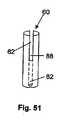
図49は、断面C−Cを有し得る缶60を示す。図50は、断面C−Cを示す。缶60は、歯154を有してよい。歯154は、缶60に対して内部にあってよい。歯154は、棚156および傾斜158を有してよい。図51は、弾性材料、例えば、ここで挙げた任意のポリマーまたは金属で形成され得る缶60を示す。缶60は、缶60の側面に溝穴88を有してよい。 FIG. 49 shows a
図52〜55は、例えば、図49〜図51で示した缶60とともに用いてよい、縫合糸6を示す。縫合糸6は、フィラメント162に固定させて取り付けた、1または複数の指状構造(もしくは指状分岐)、戻り止め(もしくはデテント;detent)、又は爪160を有してよい。爪160は、円錐形(図52に示す)であってよく、角度の付いた又は真っ直ぐなタブ(図53に示す)、略滴形状(図54に示す)、球(図55に示す)またはそれらの組み合わせであってよい。滴形状の爪160の上部は、フィラメント162に向かって内向きに凹部を形成していてよい。図52〜図55で示される縫合糸6は、適当な缶60を通過して、自己固定的にラチェットで駆動してよく、また、所望のように有限的に調節してよい。 FIGS. 52-55 show a
図56および図57は、一体的な相補的な固定デバイスを有し得る、シートまたはガスケットボディ40の一部を示す。相補的な固定デバイスは、第2の壁セグメント164であってよい。第2の壁セグメント164は、壁52の隆起した部分であってよい。壁52は、第2の壁セグメント164とトップエッジ44との間に第1の壁セグメント166を有してよい。壁52は、第2の壁セグメント164とボトムエッジ46との間に、第3の壁セグメント168を有してよい。中空のチャンネル62は、図38〜図40に示す缶60についての中空チャンネル62と同様に、壁に沿って通っていてよい。 56 and 57 illustrate a portion of a sheet or
図58および図59は、隆起したシートセグメント172を有してよく、隆起したシートセグメント172の上方および下方に切り欠き173を有する、シート170の一部を示す。使用中、シート170を、プロテーゼ2、例えばガスケットボディ40または任意の利用可能なプロテーゼ2に取り付けて、埋め込み時間を減らすことができる。 58 and 59 show a portion of a
シート170は、複数のピースから成る心臓弁アセンブリのための縫合リングの代わりに又はそれに加えて、使用してよい。複数のピースから成る心臓弁アセンブリは、例えば、Griffinらの米国特許第6,241,765号およびRitzの米国特許第5,976,183号に開示されており、それらの両文献は引用により全体が本明細書に組み込まれる。シート170とともに使用し得る他の心臓弁アセンブリとして、例えば、アドバンテージ・バイリーフレット心臓弁、パラレル弁、フリースタイル・ステンレス大動脈弁、ハンコック(Hancock)ブタ心臓弁、ハンコック心尖左心室コネクターモデル174A、ハンコック弁付き導管モデル100、105、150、ホール・メドトロニック(Hall Medtronic)心臓弁、ホール・メドトロニック弁付き導管、モザイク(MOSAIC;登録商標)心臓弁、および無傷ブタ組織弁(メドトロニック・インコポーレイテッド(Medtronic, Inc.)、ミネアポリス、ミネソタ州);Angelini Lamina-flo弁(Cardio Carbon Company, Ltd.、英国);Bjork-Shileyシングルディスク、モノストラット(monostrut)、およびケージド(caged)ディスク型弁(Shiley, Inc. 現在存在しない、以前はカリフォルニア州);Wada-Cutter弁およびChitra Cooley-Cutter弁(Cutter Biomedical Corp.、サンディエゴ、カリフォルニア州)、Angioflex三葉ポリウレタン弁(Abiomed, Inc.、デンバー、マサチューセッツ州);ATS APシリーズ心臓弁およびATS標準心臓弁(ATS Medical, Inc.、ミネアポリス、ミネソタ州);ANNULOFLO(登録商標)弁形成リング、ANNUFLEX(登録商標)弁形成リング、CARBSEAL(登録商標)弁付き導管、ORBIS(登録商標)ユニバーサル大動脈および僧帽弁、小児用/大人用小型弁、Rシリーズ弁、SUMIT(登録商標)僧帽弁、TOP HAT(登録商標)大動脈弁、OPTIFORM(登録商標)僧帽弁、MITROFLOW SYNERGY(登録商標)PCステント付き大動脈心膜生体プロテーゼおよびSYNERGY(登録商標)STステント付き大動脈および僧帽ブタ生体プロテーゼ弁(CarboMedics Inc.、オースティン、テキサス州)、ON-X(登録商標)プロテーゼ心臓弁(MCRI(登録商標), LLC、オースティン、テキサス州);Starr-Edwards SILASTIC(登録商標)ボール弁、Starr-Edwards 1000、Starr-Edwards 1200、Starr-Edwards 1260、Starr-Edwards 2400、Starr-Edwards 6300、Starr-Edwards 6500、Starr-Edwards 6520、Carpentier-Edwardsブタ組織弁、Carpentier-Edwards心膜プロテーゼ、Carpentier-Edwards弁輪上方弁、Carpentier-Edwards弁形成リング、Duromedics弁、およびPERIMOUNT(登録商標)心臓弁(Edwards Lifesciences Corp.、イルバイン、カリフォルニア州);Cross-Jonesレンズ状ディスク弁(Pemco, Inc.);Tissuemedステント付きブタ弁(Tissuemed, Ltd.、リーズ、英国);Tekna弁(Baxter Healthcare Corp.、ディアフィールド、イリノイ州);Komp-01僧帽弁保持リング(Jyros Medical Ltd.、ロンドン、英国)、SJM(登録商標)Mastersシリーズ機械心臓弁、SJM(登録商標)Mastersシリーズ大動脈バルブ付きグラフトプロテーゼ、ST. JUDE MEDICAL(登録商標)機械心臓弁、ST. JUDE MEDICAL(登録商標)機械心臓弁Hemodynamic Plus(HP)シリーズ、SJM REGENT(登録商標)弁、TORONTO SPV(登録商標)(Stentless Porcine Valve)弁、SJM BIOCOR(登録商標)弁およびSJM EPIC(登録商標)弁(St. Jude Medical, Inc.、セントポール、ミネソタ州);Sorin Bicarbon、Sorin Carbocast、Sorin Carboseal導管、Sorin Pericarbon およびSorin Pericarbonステントレス(Snia S.p.A.、イタリア)が挙げられる。ここで説明したガスケットボディ40もまた、上記において挙げた任意の心臓弁アセンブリのガスケットボディの代わりに用いることができる。 The
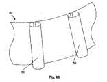
図60および61は、波状起伏形成缶60を有し得る、シートまたはガスケットボディ40を示す。缶60は、実質的に円筒形であってよい。缶60は、閉じていないシリンダーである。 60 and 61 show a sheet or
図62〜図64は、実質的に閉じた、実質的に円筒形の缶60を有し得る、シートまたはガスケットボディ40を示す。シートまたはガスケット40は、単層から成ってよく、あるいは、第1ガスケット層428および第2ガスケット層430を有し得る積層体で形成されてよい。 62-64 show a sheet or
図65は、カム174の組である、相補的な固定デバイスを有し得る、ガスケットボディ40を示す。カム174は、軸74により、ガスケットボディ40に回転可能に取り付けてよい。カム174は、卵形または楕円形であってよい。カム174は、上向きまたは下向きに開き、組のカム174において一方のカム174の主軸が他方のカム174の主軸と平行になるときに、止まる(またはロックする)ように(図27)、バイアスをかけてよい。スプール(図示せず)をカム174内に又はそれに隣り合って配置して、ガスケットボディ40が展開している間、追加の長さの縫合糸6を取り入れる及び/又は巻き取るようにしてよい。 FIG. 65 shows a
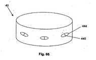
図66は、静止した(または定位の)レセプタクル44であり得る相補的な固定デバイスを有し得る、ガスケットボディ40を示す。静止したレセプタクル444は、ガスケットボディ40の外側にある。静止したレセプタクル444は、弾性的に伸縮する。静止したレセプタクル444は、エラストマーで形成されてよい。静止したレセプタクル444は、静止したチャンネル444を通過する高摩擦チャンネル446を有してよい。高摩擦チャンネル446は、静止レセプタクルを通過する曲がりくねった通路により形成されてよい。高摩擦チャンネル446の直径は、縫合糸6の直径よりも大きくてよく、または小さくてよく、あるいはそれと等しくてよい。 FIG. 66 shows a
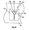
図67は、能動的な内部障害物を有し得る相補的な固定デバイス(例えば、スピンドルロック176)の第1の形状構成を示す。スピンドルロック176は、壁52に取り付けてよい。スピンドルロック176は、第1のシーティングブロック(または台座ブロック)178および第2のシーティングブロック180を有してよい。中空のチャンネル62は、第1シーティングブロック178と第2シーティングブロック180との間にあってよい。シート182は、上記第1および第2シーティングブロック178および180により規定され得る。シート182は、角度を形成していてよく、あるいは平坦であってよい。スピンドルロック176は、スピンドル183を有してよい。スピンドル183は三角形であってよく、またはシート182に適合する別の形状であってよい。スピンドル183は、ピン184に固定して取り付けてよい。ピン184は、スピンドル183の後ろで、スライドホール、スロット、またはグループ186に、スライド可能に取り付けてよい。使用中、縫合糸(図示せず)は、スピンドル183の周囲に巻き付けてよい。縫合糸6を上に引っ張って、次いで、スピンドル183を矢印に示すように上に引っ張ってよい。シート182の上方に且つ外に、スピンドル183を備えた形状構成において、縫合糸6は、スピンドル183の周囲で自由にスライドすることができる。 FIG. 67 illustrates a first configuration of a complementary fixation device (eg, spindle lock 176) that may have an active internal obstruction. The
図68は、スピンドルロック176の第2の形状構成を示す。縫合糸6を、下向きに引っ張って、次に、スピンドル183を矢印で示すように下向きに引っ張ってよい。スピンドル183をシート182内に下向きに設けた形状構成において、縫合糸6は、スピンドル183と第1および第2シーティングブロック178および180との間で抑えられ、固定され得る。 FIG. 68 shows a second shape configuration of the
製造方法
図69は、缶60をシートまたはガスケットボディ40に固定して取り付ける方法を示す。フレーム76を、シートまたはガスケットボディ40において、(矢印で示すように)穴54内に挿入してよい。それから、フレーム76は、クリンプ(または折り曲げ若しくは押し合わせ)、型打ち、溶融、ねじ止め、グロメット、スナップ嵌め、ボス(もしくは隆起)形成、接着剤、溶接、またはそれらの組み合わせにより、ボス(または隆起)形成、シートまたはガスケットボディ40に取り付けてよい。フレーム76は、フレーム76の端部にて、1または複数のスナップ隆起を有してよい。Manufacturing Method FIG. 69 shows a method in which the
図70は、缶60とシートまたはガスケットボディ40とを回転可能に取り付ける方法を示す。缶60は、1つの軸(または心棒)74を有してよい。心棒74は、(矢印で示すように)穴54に挿入してよい。 FIG. 70 shows a method for rotatably attaching the
図71は、広げて平らにして見た、シートまたはガスケットボディ40を示す。缶60は、穴54を介して、シートまたはガスケットボディ40に取り付けてよい。シートまたはガスケットボディ40に缶60を取り付けるために使用しない穴54は、第2のプロテーゼ(例えば心臓弁)をシートまたはガスケットボディ40に取り付けるのに使用してよい。 FIG. 71 shows the sheet or
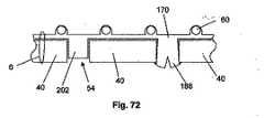
図72は、ガスケットボディ40に固定して取り付け得るシート170を示す。シート170は、例えば、ここで例示した任意のポリマーで形成し得る。缶60は、シート170内又はシート170の上にあってよく、あるいはシート170とガスケットボディ40との間にあってよい。シート170は、例えば、縫合糸6、穴54に嵌められたボス(もしくは隆起)202、穴54に嵌められたスナップボス188、またはそれらの組み合わせによって、ガスケットボディ40に取り付けられてよい。 FIG. 72 shows a
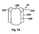
図73は、三葉形の形状構成となるように巻かれ、あるいは形成された、シートまたはガスケットボディ40を示す。ガスケットボディ40は、3つのローブ204および3つの尖点206を有してよい。図74は、スカラップ(または波形)を有する、三葉形の形状構成に巻かれ又は形成された、シートまたはガスケットボディ40を示す。ガスケットボディ40は、ローブ204または尖点206と整列した(または合わせた)、スカラップ(又は波形もしくは歯形)208を有してよい。 FIG. 73 shows the sheet or
図75は、カム174を回転可能にガスケットボディ40に取り付ける方法を示す。軸74を、矢印210で示すように、カム174において穴54内に押し込んでよい。カム174は、ガスケットボディ40に押し付けて又はガスケットボディ40の付近に配置してよく、また、軸74は、矢印212で示すように、ガスケットボディ40において穴54内に押し込んでよい。 FIG. 75 shows a method of attaching the
図76は、ポリマー(例えばシリコーン)のフレームを形成するために用いることができる、型214を示し、当該フレームから縫合糸ポート66を有する縫合リング14を形成することができる。型214は、縫合糸ポート66を形成するために、円筒形および/または円錐形の突起216を有していてよい。型の外壁448は、型のベース450の半径方向の外側エッジから、半径方向に内向きに延びていてよい。型の外壁448は、フレアまたはスカート70の上部を形成し得る。型の内壁452は、型のベース450の半径方向の内側エッジから、実質的に垂直に延びていてよい。当業者は、型214を用いて縫合リングを製造できる。 FIG. 76 shows a
図21に示すように、タブ48は、ガスケットボディ40のセクションであってよく、その周囲で、約180°の切れ目を形成して、タブ48を形成するガスケットボディ40のセクションが連結するようにしてよい。切れ目は以下に説明するいずれの方法で形成してもよい。 As shown in FIG. 21, the
固定デバイス20、綿撒糸16、ガスケットボディ40、タブ48、缶60、プラグ58、カム174および他のパーツは、当業者に公知の方法で製作することができる。例えば、製造技術として、モールド成形、機械加工、注型、成形(例えば圧力成形)、クリンプ、型打ち、溶融、ねじ止め、接着、溶接、打抜き、レーザ切断、放電加工(EDM)、またはそれらの組み合わせが挙げられる。 The
任意のパーツ、サブアセンブリ、または最終的な組立て後の全体としてのデバイスは、例えば、上述した薬剤を塗布するために、当業者に公知のディップコーティングまたはスプレーコーティング法により被覆してよい。管で使用する医療デバイスを被覆するために用いられる方法の一例は、Dingらの米国特許第6,358,556号にて提供されており、この文献は引用によりその全体が本明細書に組み込まれる。コーティング中の薬剤の開放を遅らせるために、当業者に公知の徐放性のコーティング方法もまた使用してよい。コーティングは、血栓形成または抗血栓性であってよい。 Any part, subassembly, or device as a whole after final assembly may be coated, for example, by dip coating or spray coating methods known to those skilled in the art to apply the drugs described above. An example of a method used to coat medical devices for use in tubes is provided in Ding et al., US Pat. No. 6,358,556, which is incorporated herein by reference in its entirety. It is. Sustained release coating methods known to those skilled in the art may also be used to delay the release of the drug during coating. The coating may be thrombus or antithrombotic.
使用方法
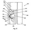
図77〜図80は、固定デバイス展開アセンブリ454を用いて固定デバイス20を展開する方法を示す。図77および図78に示すように、固定デバイス展開アセンブリ454は、図78にて矢印で示されるように、支えロッド458に回転可能に接続された、静止ロッド456を有してよい。静止ロッド456は、動的ロッド460にスライド可能に接続することができる。静止ロッド456は、ピボットピン456にて、カートリッジ464に回転可能に接続してよい。動的ロッド460は、駆動ピン466にて、カートリッジ464に回転可能に接続してよい。カートリッジ464は、固定デバイス20を、曲線をなす経路にて展開させ得る。カートリッジ464は、固定デバイス20に取り外し可能なように取り付けることができる。カートリッジ464は、イジェクション(または駆出もしくは放出)起動部材(もしくはアクティベーター)468を有してよい。Method of Use FIGS. 77-80 illustrate a method of deploying the
矢印470にて示される上向きの力を、動的ロッド460に加えてよい。動的ロッド460が上向きに移動すると、カートリッジ464は、矢印472で示すように回転することができる。カートリッジ464は、回転して、イジェクション起動部材468をイジェクションピン474に押し付けることができる。イジェクションピン474は、静的ロッド456の一部であってよく、または静的ロッド456に固定して取り付けてよい。イジェクション起動部材468は十分な力でもってイジェクションピン474内に押されると、固定デバイス20は、カートリッジ464からはずすことができる。 An upward force indicated by
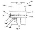
カバー476は、静的ロッド456にスライド可能に取り付けてよい。カバー476は、使用中、静的ロッド456をカバーするために、下向きにスライドさせてよい(カバー476は、図77および図78において例示のために開いている)。カバー476が静的ロッド456を覆っていると、カバー476は、固定デバイス展開アセンブリ454のエレメントを保護することができ、また、動的ロッド460およびカートリッジ464に対して付加的な支持を与えることができる。 Cover 476 may be slidably attached to
固定デバイス展開アセンブリ454は、ガスケットボディ40内に配置することができる。静的ロッド456は、第1の展開ガイド478を有してよい。支えロッド458は、第2の展開ガイド480を有してよい。固定デバイス展開アセンブリ454は、ガスケットボディ40上で適当なグルーブまたはノッチ内に第1および第2の展開ガイドを嵌めることによって、ガスケットボディ40と自己整列する。ガスケットボディ40に静的ロッド456および支えロッド458を用いて圧力を加えることにより、固定デバイス展開アセンブリ454を、所定の位置にしっかりと保持することができる。固定デバイス展開アセンブリ454がガスケットボディ40と整列すると、固定デバイス20を、窓42を経由して展開させることができる。 The fixation
図79および80は、固定デバイス20を展開するカートリッジ464を示す。カートリッジ464は、第1の外側パネル482、第1の外側パネル482に隣り合うロードパネル484、ロード(または装着もしくは負荷)パネル484に隣り合う第2の外側パネル(例示のために図示せず)を有してよい。カートリッジ464は、ピボットピン462に回転可能に取り付けるために、ピボットポート486を有してよい。カートリッジ464は、駆動ピン466に回転可能に取り付けるために、ドライブポート488を有してよい。 79 and 80 show a
イジェクションセクション490は、ロードパネル484に、ジョイント492にて回転可能に取り付けられる。イジェクション起動部材468は、イジェクションセクション490の突出部分であってよい。固定デバイス20のロックセクション494は、装着カプセル496内にあってよい。ロックセクション494または固定部材20の他の部分は、縫合糸6に取り付けられていてよい(図示せず)。装着カプセル496は、イジェクションセクション490およびイジェクションリップ498により規定してよい。イジェクションリップ498は、ロードパネル484の一部であってよい。 The
矢印500で示すように、イジェクションピン498を、イジェクション起動部材468に抗して押すと、イジェクションセクション490は、矢印502で示すように、回転することができ、固定デバイス20をカートリッジ464から解放する。イジェクションピン474をイジェクション起動部材468に対して押し付けることを開始した後、イジェクションセクション490が回転する前に、ロックセクション494は、突出し力を、イジェクションリップ498に加えることができる。突出し力は、イジェクションセクション490が回転し得る前に、ロックセクション494および/またはイジェクションリップ498および/またはイジェクションセクション490を、変形させるのに十分に大きいものであることを要する。大きな突出し力は、展開したときに、固定デバイス20を、カートリッジ464からジャンプさせる又は送り出させる。ジャンプまたは送り出しはまた、固定デバイスの展開アセンブリ454のユーザーに、固定デバイス20の展開についての触知可能なフィードバックを与える。 When the
第2のカートリッジ(図示せず)を、カートリッジ464の取り付けと同様にではあるが、上下を逆にして、動的ロッド460に取り付けることができる。第2のカートリッジの固定デバイス20が送られて、図84に示すように、カートリッジ464の固定デバイス20と重なってよい。第2のカートリッジのドライブポートは、第2のカートリッジの駆動ピンに回転可能に取り付けてよい。第2のカートリッジのピボットポート(図示せず)は、イジェクションピン474に回転可能に取り付けてよい。ピボットピン462は、第2のカートリッジに関して、イジェクションピンとして作用し得る。 A second cartridge (not shown) can be attached to the
図81〜83は、例えば、生体心臓組織である第1の塊218を、例えばガスケットボディ40である第2の塊に固定する方法を示す。ガスケットボディ40は、組織218の隣に配置してよい。アプリケータアセンブリ220を、窓42の隣に、かつ窓42と整列して、配置してよい。ガスケットボディ40は、布または縫合リング14により被覆することができる。 81 to 83 show a method of fixing the
アプリケータアセンブリ220は、ボトムマウント224に固定して取り付けてよいトップマウント222を有してよい。アプリケータアセンブリ220は、トップマウント222および/またはボトムマウント224にスライド可能に取り付けられ得る、プレス226を有してよい。マウント222および224は、それぞれローディングノッチ228を有してよい。図81に示すように、固定デバイス20は、ローディングノッチ228内に装着してよく、また、固定デバイス20はプレス226に押し付けられてよい。固定デバイス20は、装着されたときにノッチ228を完全に塞ぎ、あるいはノッチ228は固定デバイス20が拡張するために利用可能なスペースを有してよい。装着ノッチ228の間の距離は、ローディングノッチ高さ506であり得る。ローディングノッチ高さ506は、約1.27mm(0.050インチ)〜約12.7mm(0.500インチ)であってよく、例えば、約3.20mm(0.126インチ)であってよい。 The
図82において矢印で示すように、プレス226は組織218に向かって、(矢印で示すように)スライド可能に移動させることができ、プレス226は、折り目338にて又はその付近で、固定デバイス20と接触して、固定デバイス20を押すことができる。固定デバイス20は、拡張して、ノッチ20を塞いでよく、および/または固定デバイス20は変形し得る。突起24は、組織218を通って移動し得る。 As shown by the arrows in FIG. 82, the
プレス226がベース22に真っ直ぐな面を形成させる前に、またはベース22が弾性的に図81に示すような形状構成に戻り得る前に、プレス226は、図81に示す位置に戻すことができ、かつ固定デバイス20を組織218から取り除くことができる。このようにして、組織218の部分は、固定デバイス20を完全に展開させる前に、突起24を用いて試験することができる。 The
図83は、固定デバイス20を完全に展開させることを示す。プレス226は、組織218に向かって、(矢印で示すように)十分に遠くにスライドさせて、固定デバイス20をノッチ228から出て行かせてよい。窓42は、固定デバイス20が完全に展開したときに、例えば、締まり嵌めまたはくさび止めにより、固定デバイス20をガスケットボディ40内に固定する寸法を有するようにしてよい。 FIG. 83 shows the
突起24は、湾曲している必要はないが、突起24が湾曲しており、図81〜図83に示すように、突起24が曲線的な動きを用いて展開される場合には、組織218へのダメージを最小限にすることができる。固定デバイス20が展開される前において、固定デバイス20は、プレス226の長手方向の軸の周囲で任意の角度に向けられていてよい。 The
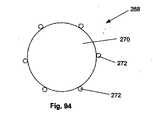
図84は、(図5に示す固定デバイスに類似する)2つの固定デバイスを示し、固定デバイスは、窓42で展開して、組織218にガスケットボディ40を固定し得る。固定デバイス20は、保持力を実質的に最大限にするように配置してよく、例えば、固定デバイス20は、窓42において実質的に同じ位置に配置することができ、実質的に相対する向きで組織218を経由して展開させてよい。 FIG. 84 shows two fixation devices (similar to the fixation device shown in FIG. 5), which can be deployed in the
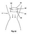
図85〜87は、トップエッジ44に取り付けられた予め展開されたタブ48、およびボトムエッジ46に取り付けられた追加のタブ48を有し得るガスケットボディ40を展開する方法を示す。ガスケットボディ40は、図85にて矢印で示すように、管4を経由させて降下させてよい。図86に示すように、ガスケットボディ40は、経弁輪空間10に配置してよい。トップエッジ44に取り付けられるタブ48は、管の壁内にひっかけて、ガスケットボディ40を管4に取り付けてよい。 FIGS. 85-87 illustrate a method of deploying a
図87は、タブ48(例えば、ボトムエッジ46に取り付けられたタブ48)を展開させる方法を示す。タブ展開アセンブリ230を、ガスケットボディ40に隣り合うように配置することができる。 FIG. 87 illustrates a method for unfolding tab 48 (eg,
タブ展開アセンブリ230は、第1のアンビル(または金床)232および第2のアンビル234を有してよい。ケーブル、ロッド、またはライン236(もしくは紐)(ここでは例示のためにライン236と呼ぶ)を、第1のアンビル232にアンカーポイント238にて、固定して取り付けてよい。ライン236は、第2のアンビル234を通過して、第2のアンビル234にスライド可能に取り付けてよい。ライン236は、第1のアンビル232を通過して、第1のアンビル232にスライド可能に取り付けてよい。ライン236の自由端部240は、弁輪上方空間8内に又は当該空間8を越えて、延びることができる。 The
アンビル232および234は、湾曲した面を有してよい。面242は、タブ48のすぐ隣に配置してよい。矢印244で示すように、ライン236の自由端240が引っ張られると、矢印236で示すように、第1アンビル233と第2アンビル234は互いの方に向かって動く。それから、アンビル232および234はタブ48に新しい形態を取らせる。タブ48に新しい形態を取らせることは、タブ48を湾曲させること、およびタブ48を管壁内に押し込むことを含む。アンビル232および234は、必要な場合には、管の壁内に圧入させて、タブ48の新形態を完成させてよい。
図88は、ループを有するスネア248が缶60内に装着された、図23に示すガスケットボディ40を示す。(ガスケットボディ40の前半分におけるスネア248のみを、例示のために示す。)スネア248は、相補的な固定デバイス(例えば、カム174)を使用して、任意のガスケットボディ40とともに用いることができる。スネア248は、当業者に公知の適当な任意のスネア248、例えば、直径約0.2mm(0.006インチ)の直径を有するステンレス鋼スネアであってよい。図89は、既に管壁を通過し、スネア248を通過した、縫合糸6を示す。シングルステッチおよびマットレス・ステッチ(両方とも当業者に公知である)を使用して、縫合糸6を管壁に取り付けてよい。それから、矢印で示すように、スネア248を引っ張って、缶60を通過させて、それにより、縫合糸6を缶60を介して供給する。 FIG. 88 shows the
全ての所望の縫合糸6が缶60を介して供給されると、ガスケットボディ40は、図90に示すように、弁輪上方空間8と経弁輪空間10との間のショルダー上に、降下させられる。降下は、ガスケットボディ40を合わせるために、位置合わせスティックまたはバルブホルダー(図示せず)の補助を得て、当業者に公知のように実施してよい。缶60は、クリンプさせてよく、塞いでよく、あるいは、固定(またはロック)してよく、また、余分な縫合糸6は、切り取って、取り除いてよい。 When all the desired
図91に示すように、遠隔操作によるクリンプツール250を用いて、缶60をクリンプさせてよい。遠隔操作によるクリンプツール250は、押しつぶし部材254にピボット256にて回転可能に取り付けられたアーム252を有してよい。ガスケットボディ40に取り付けられた缶60は、押しつぶし部材254とアーム252との間に装着されてよい。押しつぶし部材254は、押しつぶしヘッド508を有してよい。アクチュエータボール258は、引っ張りライン(または紐)260に固定して取り付けてよい。アクチュエータボール258は、アーム252と押しつぶし部材254との間のボールキャビティ(または空洞)262内にあってよい。押しつぶし部材254は、ボール258がボールキャビティ262から出て行くのを防止し得る。引っ張りライン260が矢印264で示すように引っ張られると、ボール258は押しつぶし部材254を矢印266の方向に押しやる。それから、押しつぶしヘッド508は、缶60を押しつぶし得る。 As shown in FIG. 91, the
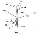
図92は、近位端部(図示せず)にて、押しつぶし部材254に固定して取り付けられ得るアーム252を有し得る、遠隔操作による別のクリンプツール250を示す。スライドテンショナー510は、アーム252および押しつぶし部材254にスライド可能に取り付けることができる。スライドテンショナー510は、非変形性であってよい。スライドテンショナー510は、アームおよび押しつぶし部材254の折り曲げ歪みを拘束し得る。スライドテンショナー510は、アーム252と押しつぶし部材254との間で、曲げストレッサー512を有してよい。押しつぶし部材254は、弾性的にバイアスがかけられて、アーム252から離れた状態にされ、および/または曲げストレッサー512は、アーム252および/または押しつぶし部材254に曲げ歪みが生じるのを強制する。アーム252および/または押しつぶし部材254の長さの全部または一部にわたる曲げ歪みは、押しつぶし部材254を十分に曲げて、押しつぶしヘッド508とアーム252との間に缶60が嵌ることを十分に許容する。スライドテンショナー510は、矢印514で示すように、缶に向かってスライドさせられると、スライドテンショナー510は、押しつぶし部材254を、矢印266の方向に押しやる。 FIG. 92 shows another remotely operated
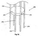
図93および図94は、ガスケットボディ40を所望の位置へ埋め込むために用いることができる、展開ツール268を示す。展開ツール268は、支持体270(例えば、ディスク)を有してよい。展開ツール268は、実質的に平行な係合デバイス(例えば、チューブ272)を有してよい。チューブ272は、アタッチメントエリア516にて、支持体270に固定して取り付けられてよい。チューブ272のうち幾つか又は全部は、支持体270に取り付けられていなくてよい。例えば、チューブ272のうち約3本を支持体に取り付けなくてよい。チューブ272は中空であってよい。チューブ272は、実質的に円筒形であってよい。チューブ272は、チューブ端部274を有し得る。チューブ端部274は、端部が開放されていてよい。チューブ端部274は、弾性であってよい。 93 and 94 show a
図95は、ガスケットボディ40とともに展開ツール268を使用する方法を示す。缶60は、チューブの端部274により係合されてよい。チューブ端部274は、缶60上でフィットし、缶60を保持し得る。 FIG. 95 illustrates a method of using the
図96は、展開ツール268が缶60に係合する前の、展開ツール268および缶60およびガスケットボディ40の一部を示す。展開ツール258のチューブ端部274はリップ276を有してよい。チューブ端部274は、チューブ端部274の側部に沿ってカットされ又は形成された、係合ホール278を有してよい。係合ホールド278は、スナップボス188の周囲でスライドする寸法にされ得る。チューブ端部274は、チューブ272の長さに沿って延びてよい、解放ドライバー280(例えば、中空のカテーテル)を有し得る。解放ドライバー280の内部は、器具ポート282を有してよい。チューブ端部274は、矢印で示すように、缶60に隣り合って移動させてよい。 FIG. 96 shows the
図97は、チューブ端部274が缶60に係合しはじめたときの、断面D−Dを示す。リップ276は、係合面284および解放面286を有してよい。チューブ端部274が缶60と接触すると、缶60は係合面284に接してスライドし得る。チューブ端部274は、矢印288で示すように、缶の上で押すことができ、それからチューブ端部274は矢印300に示すように、外向きに曲がることができる。それから、缶60の半径は、チューブ端部274によって収容され(または適合させられ)、チューブ端部274は缶60の長さの上をスライドし得る。 FIG. 97 shows a cross section DD when the
縫合リング14は、缶60がチューブの端部274により係合させられると、缶60から分離して、縫合リング14が実質的にチューブの端部274と干渉しないようにしてよい。チューブ端部274は、缶60の内側半径に嵌ってよく(図示せず)、リップ276は、チューブ端部274から半径方向で外向きに延び(図示せず)、縫合リング14は缶60の全体の周長に沿って、缶60に実質的に付随し得る。 The
図98および図99は、チューブ端部274が缶60に係合したときを示す。リップ276が、缶60の端部に到達すると、リップ276は、矢印で示すように、弛緩した、曲げられていない位置に戻り得る。 98 and 99 show the
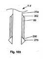
図100および図101は、保持デバイス(例えば、フラップ302)とリップ276の解放面286との間で展開している間に、固定されている缶60を示す。フラップ302は、チューブ端部274の壁から切り取ってよい。フラップ302は、弾性を有していてよい。フラップ302は、使用中、解放ドライバー280から外れて、曲がってよい。 100 and 101 show the
図102および図103は、チューブ端部274が缶60の直径内にあり、リップ276およびフラップ302が半径方向で外向きに面していることを除いては、図100および101の缶60に類似する、展開の間の固定されている缶60を示す。リップ276は、缶60の係合および解放の間、曲げを向上させるために、ノッチ、穴、溝穴を有してよく、および/または可撓性を有してよい。 102 and 103 show the
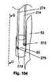
図104および図105は、缶60にて複数の係合ポート518に缶60が係合している、チューブ端部274を示す。チューブ端部274は、チューブ272の一体的な部分であってよく、またはチューブ272から分離していてよい。チューブ端部274は、チューブから半径方向に外向きにバイアスがかけられていて、外力によって半径方向に内向きに強制的に向けられてよく、あるいは、半径方向に内向きにバイアスがかけられていて、外力によって半径方向に外向きに強制的に向けられてよい。係合ポート518は、リップ276を収容し、かつリップの一次元または二次元の動きを制限するような、形状および寸法を有するようにしてよい。 104 and 105 show the
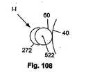
図106〜図108は、実質的に缶ギャップ520内で、缶60を側方で係合しているチューブ272を示す。チューブ272は、係合ロッド522により缶60に保持されてよい。係合ロッド522は、缶60およびチューブ272にスライド可能に取り付けられてよい。係合ロッド522が缶60から取り外されると、チューブ272および缶60を分離することができる。チューブ272は、缶60と係合し、また缶60との係合が解かれる間、缶60との接触を最小にするために、係合スロープ524を有してよい。チューブ272が缶60と側部で係合していると、チューブ272は、ガスケットボディ40のすぐ上にて、実質的に弁輪上方空間を避けることができる(または当該空間に近付かなくてよい)。 106-108 show the
図109および図110は、スネアおよび/または縫合糸6を展開する2つの方法を示す。第1のスネアおよび/または縫合糸6aは、チューブ端部274内へ、缶60を介して供給してよい。それから、第1の縫合糸6aは、チューブの窓304を通過させて、チューブ端部274から出て行かせてよい。第1の縫合糸6aは矢印306で示すように、チューブ272の外側で引っ張ってよい。 109 and 110 show two ways of deploying the snare and / or
第2のスネアおよび/または縫合糸6bは、チューブ端部274へ、缶60を介して供給してよい。それから、第2の縫合糸6bは、チューブ端部274に沿って連続し、解放ドライバー280内で器具ポート282を通過してよい。第2の縫合糸6bは、チューブ272の長さに沿って延びてよい。第2の縫合糸6bを、矢印308で示すように、チューブ272の内側で引っ張ってよい。1または複数の縫合糸6を、単一の缶60を通過させて、展開させてよい。 The second snare and / or
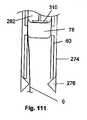
図111は、展開プロセスにおいて、プラグ78を有する断面J−Jの形態を示す。プラグ78は、器具ドライバー310(例えばカテーテル)により、矢印で示すように、器具ポート282を通過して供給してよい。プラグ78は、曲がって、解放ドライバー280内で、縫合糸6の回りで、スライドすることができる。 FIG. 111 shows a cross-sectional JJ configuration with
図112は、プラグ78が完全に展開した後の、断面J−Jの形態を示す。器具ドライバーは、プラグを缶60内に押し込み、それにより、缶の周囲で隙間のないシールを形成し、縫合糸6をプラグ78と缶60との間で圧力により固定する。 FIG. 112 shows a cross-sectional JJ configuration after the
図113および図114は、遠隔操作によるクリンプツール250を用いて、缶60を押しつぶす方法を示す、断面J−Jの形態を示す。矢印で示すように、トルクを、押しつぶし部材254に加えることができる。トルクが加えられた後、図114に示すように、缶60を押しつぶされて、缶60の一方の側の内部障害物72を缶60の他方の側の内部障害物72に押し付け、また、内部障害物72間で縫合糸6を固定してよい。缶60は変形可能であってよく、それにより、押しつぶされた後で、缶60が内部障壁72の間から縫合糸6を放出するように変形するまで、缶60は縫合糸6を内部障害物72間で、固定することができる。 113 and 114 show a cross-sectional JJ configuration that illustrates a method of crushing the
縫合糸6が展開され、ガスケットボディ40に固定されると、縫合糸6をカットして、余分の縫合糸を取り除くことができる。縫合糸6は、ハサミでカットしてよく、(例えば、チューブ端部274と缶60との間で)展開ツール264で剪断してよく、あるいはそれらを組み合わせにより切断してよい。図115〜図118は、展開ツール268から缶60の係合を解く方法を示す。図115および図116は、矢印312で示すように、解放ドライバー280を缶60に対して押し付けることを示す。チューブ端部274は、解放面286に沿って、スライドすることができ、矢印300で示すように、外向きに曲がることができ、矢印314で示すように引き込むことができる。それから、チューブ端部274は、缶60および解放ドライバー280に沿ってスライドさせることができる。図117および図118は、展開ツール268から解放された缶60を示す。リップ276は、解放ドライバー280上にあってよい。それから、展開ツール268は、埋め込みサイトから取り除くことができる。 When the
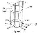
図119は、ガスケットボディ40と係合する展開ツール268を示す。チューブ端部274は、缶60に取り外し可能な用に取り付けてよい。チューブ端部274は、ネック316を介して、缶60に取り付けてよい。ネック316は、チューブ端部274の壁に穿孔された、またはチューブ端部274の壁が細くされた部分であってよい。ネック316は、缶60に直接的に取り付けてよい。 FIG. 119 shows the
図120は、ガスケットボディ40から係合が解かれた後の図19の展開ツール268を示す。ガスケットボディ40から展開ツール268の係合を解くために、ネック316を壊して、チューブ端部274を缶60から引っ張り出してよい。ネック316は、ネック316を抵抗力に抗して引っ張ることにより壊してよい。例えば、ガスケットボディ40は、展開ツール268上で引っ張る前に、移植サイトに、縫合糸6を用いて固定してよい。別の例において、電流をチューブ272に送って、ネック316を壊してよい。ネック316は、十分な電流が加えられたときに、発熱して壊れる導電性材料から成ってよい。 120 shows the
幾つかのチューブ端部274は、他のチューブ端部274が缶60に取り付けられたままである間に、缶60から取り外してよい(図示せず)。缶60になお付着していてよい後者のチューブ端部274は、後で、缶60から取り外してよい。例えば、幾つかのチューブ端部274は、チューブ端部274を缶60にまだ取り付けたままで、缶60から取り外してよい。缶60にまだ取り付けられているチューブ端部274は、側部で係合しているチューブの端部274であり得る。缶60にまだ取り付けられているチューブの端部274は、支持体270に取り付けられていなくてよい。支持体270および取り外したチューブ端部274は、弁輪上方空間8から完全に取り外すことができる。それから、ガスケットボディ40の直ぐ上方の弁輪上方空間には、医療専門家または他のデバイスが、より容易にアクセス可能となり得る。その後、缶60になお取り付けられているチューブ端部274は、ガイドロッドとして使用することができる。例えば、心臓弁デバイスの追加の部分、例えば、接続アダプター、クラウンおよび/または弁葉を、残りのチューブ端部274のいくつか又はすべてに沿って、および/またはそれらの半径方向の内側において、整列させ、かつスライドさせてよい。残りの取り付けられたチューブ端部274は、ガスケットボディ40がもはやチューブ272と係合する必要がなくなったときに、缶60から取り外すことができる。 Some tube ends 274 may be removed from the
図121および図122は、図43の固定デバイス20を使用する方法を示す。ガスケットボディ40は、弁輪上方空間8に配置することができる。図122において矢印で示すように、展開力を、固定デバイス20に加えてよい。固定デバイス20は、スライドロッド432に沿って、第1のガイドブロック434と第2のガイドブロック436との間でスライドさせることができる。先端440は、ガスケットボディ40を心臓組織218に固定し得る。固定デバイス20が展開されると、第1および第2のガイドブロック434および436が、固定デバイス20の形状を弾性的に変化させて、固定デバイス20と第1ガイドブロック434および/または第2ガイドブロック436との間で摩擦ロックを生じさせる。 121 and 122 illustrate a method of using the
ガスケットボディ40上の各固定デバイス20は、選択的に展開してよく、または展開させなくてよい。展開された各固定デバイス20は、展開力を逆転させることによって、心臓組織218から取り外すことができる。 Each
図123は、図32に示す缶60の弾力的な性質を示す。缶60は、(矢印で示すような)外からの拡開力によって開いて、縫合糸6またはスネア248が中空のチャンネル62を通過することを許容してよい。中空のチャンネル62を介して縫合糸6またはスネア248を、最小の必要な牽引力よりも大きい力で引っ張ることは、外からの拡開力がなくても、中空のチャンネル62を開くのに十分となり得る。外からの拡開力が取り除かれ、及び/又は縫合糸6もしくはスネア248が最小の必要な牽引力よりも大きい力でもはや引っ張られなくなったとき、缶60は、図32に示すような形状構成に弾性的に戻るであろう。最小の必要な牽引力は、当業者に公知のように、缶60の寸法および材料によって決定され得る。 FIG. 123 shows the elastic nature of the
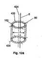
図124は、図33に示す缶60を用いる方法を示す。縫合糸6は、缶60と拡張(もしくは膨張)可能な障害物100との間に供給してよい。それから、拡張可能な障害物100は、矢印で示すように、半径方向に拡張する。例えば、バルーンカテーテルを展開させてよく、および/または自己拡張型ステントを解放してよい。 FIG. 124 shows a method using the
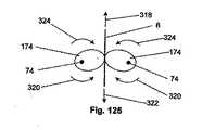
図125は、カム174を、カム174の間のスネア248または縫合糸6(図125においては例示のために縫合糸6として示す)とともに示す。カム174は、自己ロックカムクリートであってよい。図125に示すカム174は、バイアスがかけられて、上向きに開いてよい。縫合糸6が矢印318で示すように上向きに引っ張られると、カム174は矢印320で示すように自由に回転することができる。縫合糸6が矢印322で示すように下向きに引っ張られると、カム174は、カム174同士が互いに接触するまで、矢印324で示すように回転することができる。接触点にて、カム174は、所定の位置に固定され(またはロックされ)、縫合糸6がさらに下向きに移動することを禁止する。 FIG. 125 shows
図126は、図21に示すガスケットボディ40を使用する方法を示す。ガスケットボディ40が埋め込みサイトに配置されると、タブ48は矢印で示すように外側に向けることができる。下側及び/または外側に向けられたタブ48は、埋め込みサイトに係合し得る。係合は、増加した摩擦、埋め込みサイトの穴あけ、および/または埋め込みサイトからタブ48内への成長(または伸びること)に由来し得る。 126 shows a method of using the
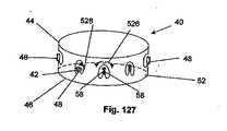
図127は、図22に示すガスケットボディ40を使用する方法を説明する。ガスケットボディ40が埋め込みサイトに配置されると、サイドウィング58が矢印526で示すように内向きにカールして、縫合糸6を通過させ得るシリンダーを形成し得る。縫合糸6が新しく形成されたシリンダーを通過した後、サイドウィング58が潰されて、縫合糸6をガスケットボディ40に固定し得る。 FIG. 127 illustrates a method of using the
タブ48は、矢印528に示すように外側に曲げられて、図126のガスケットボディ40のタブ48と同様に、埋め込みサイトに係合してよい。タブ48は、内側に曲げてよく、曲げなくてよく、またはタブごとに外向きに曲げること、内側に曲げること、および曲げないことを任意に組み合わせてよい。縫合糸6は、タブ48が内側にまげられ、外側に曲げられ、あるいは曲げられていないとしても、タブ48においてレセプタクル42を経由して通過させることができる。
図128は、矢印で示すように、ガスケットボディ40を、接続アダプター326および弁葉530を有し得る心臓弁クラウン328(例えば、Laneの米国特許6,371,983号、当該文献は引用に本明細書に組み込まれる)に取り付ける方法を示す。ガスケットボディ40は、例えば、1ピースバルブ、2ピースバルブ、機械弁、および/または生体弁とともに、使用してよい。可撓性を有するガスケットボディ40、および/または(例えば、縫合リング14内に缶60全体を収容することにより)ガスケットボディ40から吊り下げられている缶60は、接続アダプター326および/または心臓弁クラウン328へのストレスを最小にし、ガスケットボディ40と接続アダプター326および/または心臓弁クラウン328との間で係合の品質を最大にし得る。 128 shows a
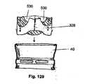
ガスケットボディ40を接続アダプター326および/または心臓弁クラウン328に取り付ける方法の例は、米国特許出願10/327821に開示されている。クラウン328および/または接続アダプター326は、その周長方向において弾性であってよく、あるいは、周長方向および/または半径方向において調節可能であってよい。クラウン328および/または接続アダプター326は、米国特許出願10/327821に開示されている第1のプロテーゼにより採用されるエレメントに類似するエレメントを使用することにより、周長方向および/または半径方向の調節を可能にする形態を有し得る。ガスケットボディ40は、図129に示すように、クラウン328に直接的に取り付けてよい。ガスケットボディ40は、図130に示すように、弁葉530に直接的に取り付けてよい。弁葉530は、単独で、当業者に公知の方法でガスケットボディ40に挿入してよい。弁葉530は、図130に示すように、弁葉が弁葉ガスケット532により保持されている間に、挿入されてしまってよい。ガスケットボディ40は、弁葉530に直接的に取り付けられなくてもよい。 An example of how to attach
当業者には、本発明の範囲から逸脱することなく、この開示および採用される等価物に対して、様々な変更および修正を施してよいことが明らかであろう。任意の形態とともに示すエレメントは、特定の形態に関する例示的なものであり、この開示の範囲内で他の形態に用いることができる。 It will be apparent to those skilled in the art that various changes and modifications can be made to this disclosure and the equivalents employed without departing from the scope of the invention. Elements shown with any form are exemplary for the particular form and can be used for other forms within the scope of this disclosure.
Claims (75)
Translated fromJapaneseガスケットボディが、内側ガスケット半径、外側ガスケット半径、および相補的なアタッチメントデバイスをさらに含み、
相補的なアタッチメントデバイスが、内側アタッチメント半径および外側アタッチメント半径を含み、
内側ガスケット半径、外側ガスケット半径、内側アタッチメント半径および外側アタッチメント半径が、長手方向の軸から測定され、
外側アタッチメント半径が外側ガスケット半径よりも大きい、
デバイス。A device for connecting a heart valve device to a first mass, comprising a gasket body, the gasket body having a longitudinal axis central to the gasket body;
The gasket body further includes an inner gasket radius, an outer gasket radius, and a complementary attachment device;
The complementary attachment device includes an inner attachment radius and an outer attachment radius;
The inner gasket radius, outer gasket radius, inner attachment radius and outer attachment radius are measured from the longitudinal axis,
The outer attachment radius is larger than the outer gasket radius,
device.
第1の開口が、第1の端部と第2の端部との間にあり、
相補的なアタッチメントデバイスが、第1の開口と第2の開口との間で第1の長さ部分を、さらに含む、請求項46に記載のデバイス。The complementary attachment device further includes a first end, a second end, and a second opening between the first opening and the second end;
A first opening is between the first end and the second end;
47. The device of claim 46, wherein the complementary attachment device further comprises a first length portion between the first opening and the second opening.
ガスケットボディが、内側ガスケット半径、外側ガスケット半径、および相補的なアタッチメントデバイスをさらに含み、
相補的なアタッチメントデバイスが、内側アタッチメント半径および外側アタッチメント半径を含み、
内側ガスケット半径、外側ガスケット半径、内側アタッチメント半径および外側アタッチメント半径が、長手方向の軸から測定され、
内側アタッチメント半径が内側ガスケット半径よりも小さい
デバイス。A device for connecting a heart valve device to a first mass, comprising a gasket body, the gasket body having a longitudinal axis central to the gasket body;
The gasket body further includes an inner gasket radius, an outer gasket radius, and a complementary attachment device;
The complementary attachment device includes an inner attachment radius and an outer attachment radius;
The inner gasket radius, outer gasket radius, inner attachment radius and outer attachment radius are measured from the longitudinal axis,
A device with an inner attachment radius smaller than the inner gasket radius.
ガスケットボディ、および
ガスケットボディに取り付けられた独立したレセプタクル
を含む、デバイス。A device for connecting a heart valve device to the first mass;
A device comprising a gasket body and a separate receptacle attached to the gasket body.
ガスケットボディの半径方向の外側に配置された相補的なアタッチメントデバイス
を含む、心臓弁デバイスであって、
相補的なアタッチメントデバイスが、アタッチメントデバイスを収容するように構成されている、心臓弁デバイス。
A heart valve device comprising a gasket body and a complementary attachment device disposed radially outward of the gasket body,
A heart valve device, wherein the complementary attachment device is configured to receive the attachment device.
Applications Claiming Priority (3)
| Application Number | Priority Date | Filing Date | Title |
|---|---|---|---|
| US10/646,639 | 2003-08-22 | ||
| US10/646,639US8021421B2 (en) | 2003-08-22 | 2003-08-22 | Prosthesis heart valve fixturing device |
| PCT/US2004/026922WO2005020842A2 (en) | 2003-08-22 | 2004-08-19 | Prosthesis fixturing devices |
Publications (3)
| Publication Number | Publication Date |
|---|---|
| JP2007533348Atrue JP2007533348A (en) | 2007-11-22 |
| JP2007533348A5 JP2007533348A5 (en) | 2008-01-10 |
| JP4796963B2 JP4796963B2 (en) | 2011-10-19 |
Family
ID=34194575
Family Applications (1)
| Application Number | Title | Priority Date | Filing Date |
|---|---|---|---|
| JP2006524036AExpired - Fee RelatedJP4796963B2 (en) | 2003-08-22 | 2004-08-19 | Prosthesis fixation device and method of use |
Country Status (4)
| Country | Link |
|---|---|
| US (2) | US8021421B2 (en) |
| EP (1) | EP1659981B1 (en) |
| JP (1) | JP4796963B2 (en) |
| WO (1) | WO2005020842A2 (en) |
Families Citing this family (308)
| Publication number | Priority date | Publication date | Assignee | Title |
|---|---|---|---|---|
| US8366769B2 (en) | 2000-06-01 | 2013-02-05 | Edwards Lifesciences Corporation | Low-profile, pivotable heart valve sewing ring |
| US6409758B2 (en)* | 2000-07-27 | 2002-06-25 | Edwards Lifesciences Corporation | Heart valve holder for constricting the valve commissures and methods of use |
| WO2002019951A1 (en)* | 2000-09-07 | 2002-03-14 | Viacor, Inc. | Fixation band for affixing a prosthetic heart valve to tissue |
| US7097659B2 (en)* | 2001-09-07 | 2006-08-29 | Medtronic, Inc. | Fixation band for affixing a prosthetic heart valve to tissue |
| US7201771B2 (en) | 2001-12-27 | 2007-04-10 | Arbor Surgical Technologies, Inc. | Bioprosthetic heart valve |
| US7578843B2 (en) | 2002-07-16 | 2009-08-25 | Medtronic, Inc. | Heart valve prosthesis |
| US7959674B2 (en)* | 2002-07-16 | 2011-06-14 | Medtronic, Inc. | Suture locking assembly and method of use |
| US8551162B2 (en) | 2002-12-20 | 2013-10-08 | Medtronic, Inc. | Biologically implantable prosthesis |
| DE602004029159D1 (en)* | 2003-05-28 | 2010-10-28 | Cook Inc | |
| US8021421B2 (en) | 2003-08-22 | 2011-09-20 | Medtronic, Inc. | Prosthesis heart valve fixturing device |
| US7556647B2 (en)* | 2003-10-08 | 2009-07-07 | Arbor Surgical Technologies, Inc. | Attachment device and methods of using the same |
| US8840663B2 (en)* | 2003-12-23 | 2014-09-23 | Sadra Medical, Inc. | Repositionable heart valve method |
| US8603160B2 (en)* | 2003-12-23 | 2013-12-10 | Sadra Medical, Inc. | Method of using a retrievable heart valve anchor with a sheath |
| US7871435B2 (en) | 2004-01-23 | 2011-01-18 | Edwards Lifesciences Corporation | Anatomically approximate prosthetic mitral heart valve |
| US7597711B2 (en) | 2004-01-26 | 2009-10-06 | Arbor Surgical Technologies, Inc. | Heart valve assembly with slidable coupling connections |
| US20090132035A1 (en)* | 2004-02-27 | 2009-05-21 | Roth Alex T | Prosthetic Heart Valves, Support Structures and Systems and Methods for Implanting the Same |
| CA2813136A1 (en)* | 2004-02-27 | 2005-09-15 | Aortx, Inc. | Prosthetic heart valve delivery systems and methods |
| US20070073387A1 (en)* | 2004-02-27 | 2007-03-29 | Forster David C | Prosthetic Heart Valves, Support Structures And Systems And Methods For Implanting The Same |
| JP2007535342A (en) | 2004-03-11 | 2007-12-06 | パーキュテイニアス カルディオバスキュラー ソリューションズ ピー・ティー・ワイ リミテッド | Percutaneous prosthetic heart valve |
| US20050228494A1 (en)* | 2004-03-29 | 2005-10-13 | Salvador Marquez | Controlled separation heart valve frame |
| US8349001B2 (en)* | 2004-04-07 | 2013-01-08 | Medtronic, Inc. | Pharmacological delivery implement for use with cardiac repair devices |
| DE102005003632A1 (en) | 2005-01-20 | 2006-08-17 | Fraunhofer-Gesellschaft zur Förderung der angewandten Forschung e.V. | Catheter for the transvascular implantation of heart valve prostheses |
| US8574257B2 (en)* | 2005-02-10 | 2013-11-05 | Edwards Lifesciences Corporation | System, device, and method for providing access in a cardiovascular environment |
| US20060195186A1 (en) | 2005-02-28 | 2006-08-31 | Drews Michael J | Connectors for two piece heart valves and methods for implanting such heart valves |
| US8083793B2 (en)* | 2005-02-28 | 2011-12-27 | Medtronic, Inc. | Two piece heart valves including multiple lobe valves and methods for implanting them |
| US8608797B2 (en) | 2005-03-17 | 2013-12-17 | Valtech Cardio Ltd. | Mitral valve treatment techniques |
| US7513909B2 (en) | 2005-04-08 | 2009-04-07 | Arbor Surgical Technologies, Inc. | Two-piece prosthetic valves with snap-in connection and methods for use |
| US8333777B2 (en) | 2005-04-22 | 2012-12-18 | Benvenue Medical, Inc. | Catheter-based tissue remodeling devices and methods |
| JP4912395B2 (en) | 2005-05-24 | 2012-04-11 | エドワーズ ライフサイエンシーズ コーポレイション | Rapid placement prosthetic heart valve |
| US8211169B2 (en) | 2005-05-27 | 2012-07-03 | Medtronic, Inc. | Gasket with collar for prosthetic heart valves and methods for using them |
| US8951285B2 (en) | 2005-07-05 | 2015-02-10 | Mitralign, Inc. | Tissue anchor, anchoring system and methods of using the same |
| US7776084B2 (en)* | 2005-07-13 | 2010-08-17 | Edwards Lifesciences Corporation | Prosthetic mitral heart valve having a contoured sewing ring |
| US20070016288A1 (en)* | 2005-07-13 | 2007-01-18 | Gurskis Donnell W | Two-piece percutaneous prosthetic heart valves and methods for making and using them |
| US7967857B2 (en) | 2006-01-27 | 2011-06-28 | Medtronic, Inc. | Gasket with spring collar for prosthetic heart valves and methods for making and using them |
| US8147541B2 (en)* | 2006-02-27 | 2012-04-03 | Aortx, Inc. | Methods and devices for delivery of prosthetic heart valves and other prosthetics |
| US7749266B2 (en)* | 2006-02-27 | 2010-07-06 | Aortx, Inc. | Methods and devices for delivery of prosthetic heart valves and other prosthetics |
| JP5102279B2 (en)* | 2006-03-10 | 2012-12-19 | メドトロニック,インコーポレイテッド | Artificial valve introducer, method for producing the same and method for using the same |
| JP2009535128A (en)* | 2006-04-29 | 2009-10-01 | アーバー・サージカル・テクノロジーズ・インコーポレイテッド | Multi-part prosthetic heart valve assembly and apparatus and method for delivering the same |
| US8021161B2 (en)* | 2006-05-01 | 2011-09-20 | Edwards Lifesciences Corporation | Simulated heart valve root for training and testing |
| US8500799B2 (en)* | 2006-06-20 | 2013-08-06 | Cardiacmd, Inc. | Prosthetic heart valves, support structures and systems and methods for implanting same |
| EP2035723A4 (en) | 2006-06-20 | 2011-11-30 | Aortx Inc | Torque shaft and torque drive |
| WO2007149933A2 (en) | 2006-06-21 | 2007-12-27 | Aortx, Inc. | Prosthetic valve implantation systems |
| US9408607B2 (en) | 2009-07-02 | 2016-08-09 | Edwards Lifesciences Cardiaq Llc | Surgical implant devices and methods for their manufacture and use |
| US9585743B2 (en) | 2006-07-31 | 2017-03-07 | Edwards Lifesciences Cardiaq Llc | Surgical implant devices and methods for their manufacture and use |
| EP3360509B1 (en) | 2006-07-31 | 2022-06-22 | Syntheon TAVR, LLC | Sealable endovascular implants |
| JP2010502395A (en)* | 2006-09-06 | 2010-01-28 | エーオーテックス, インコーポレイテッド | Prosthetic heart valve, implantation system and method |
| US9883943B2 (en) | 2006-12-05 | 2018-02-06 | Valtech Cardio, Ltd. | Implantation of repair devices in the heart |
| US11259924B2 (en) | 2006-12-05 | 2022-03-01 | Valtech Cardio Ltd. | Implantation of repair devices in the heart |
| US7753949B2 (en)* | 2007-02-23 | 2010-07-13 | The Trustees Of The University Of Pennsylvania | Valve prosthesis systems and methods |
| US8070802B2 (en)* | 2007-02-23 | 2011-12-06 | The Trustees Of The University Of Pennsylvania | Mitral valve system |
| US11660190B2 (en) | 2007-03-13 | 2023-05-30 | Edwards Lifesciences Corporation | Tissue anchors, systems and methods, and devices |
| US7896915B2 (en) | 2007-04-13 | 2011-03-01 | Jenavalve Technology, Inc. | Medical device for treating a heart valve insufficiency |
| US9814611B2 (en) | 2007-07-31 | 2017-11-14 | Edwards Lifesciences Cardiaq Llc | Actively controllable stent, stent graft, heart valve and method of controlling same |
| US9566178B2 (en) | 2010-06-24 | 2017-02-14 | Edwards Lifesciences Cardiaq Llc | Actively controllable stent, stent graft, heart valve and method of controlling same |
| AU2008344915B2 (en)* | 2007-12-06 | 2013-05-30 | Valikapathalil Mathew Kurian | An implantable mechanical heart valve assembly |
| ES2781686T3 (en) | 2007-12-14 | 2020-09-04 | Edwards Lifesciences Corp | Leaflet Junction Frame for a Prosthetic Valve |
| US9044318B2 (en) | 2008-02-26 | 2015-06-02 | Jenavalve Technology Gmbh | Stent for the positioning and anchoring of a valvular prosthesis |
| BR112012021347A2 (en) | 2008-02-26 | 2019-09-24 | Jenavalve Tecnology Inc | stent for positioning and anchoring a valve prosthesis at an implantation site in a patient's heart |
| US8382829B1 (en) | 2008-03-10 | 2013-02-26 | Mitralign, Inc. | Method to reduce mitral regurgitation by cinching the commissure of the mitral valve |
| US8313525B2 (en) | 2008-03-18 | 2012-11-20 | Medtronic Ventor Technologies, Ltd. | Valve suturing and implantation procedures |
| PL4223257T3 (en) | 2008-06-06 | 2024-09-23 | Edwards Lifesciences Corporation | LOW-PROFILE TRANSCATHETIC HEART VALVE |
| EP2296744B1 (en) | 2008-06-16 | 2019-07-31 | Valtech Cardio, Ltd. | Annuloplasty devices |
| US8652202B2 (en) | 2008-08-22 | 2014-02-18 | Edwards Lifesciences Corporation | Prosthetic heart valve and delivery apparatus |
| EP2352443A2 (en)* | 2008-09-05 | 2011-08-10 | Papworth Hospital NHS Foundation Trust | Sutureless connector |
| US8790387B2 (en) | 2008-10-10 | 2014-07-29 | Edwards Lifesciences Corporation | Expandable sheath for introducing an endovascular delivery device into a body |
| US8449625B2 (en) | 2009-10-27 | 2013-05-28 | Edwards Lifesciences Corporation | Methods of measuring heart valve annuluses for valve replacement |
| EP3613383B1 (en) | 2008-11-21 | 2023-08-30 | Percutaneous Cardiovascular Solutions Pty Limited | Heart valve prosthesis |
| EP2370138B1 (en) | 2008-11-25 | 2020-12-30 | Edwards Lifesciences Corporation | Apparatus for in situ expansion of prosthetic device |
| US8308798B2 (en) | 2008-12-19 | 2012-11-13 | Edwards Lifesciences Corporation | Quick-connect prosthetic heart valve and methods |
| US8241351B2 (en) | 2008-12-22 | 2012-08-14 | Valtech Cardio, Ltd. | Adjustable partial annuloplasty ring and mechanism therefor |
| US8715342B2 (en) | 2009-05-07 | 2014-05-06 | Valtech Cardio, Ltd. | Annuloplasty ring with intra-ring anchoring |
| US10517719B2 (en) | 2008-12-22 | 2019-12-31 | Valtech Cardio, Ltd. | Implantation of repair devices in the heart |
| WO2010073246A2 (en) | 2008-12-22 | 2010-07-01 | Valtech Cardio, Ltd. | Adjustable annuloplasty devices and adjustment mechanisms therefor |
| US8911494B2 (en) | 2009-05-04 | 2014-12-16 | Valtech Cardio, Ltd. | Deployment techniques for annuloplasty ring |
| US9011530B2 (en) | 2008-12-22 | 2015-04-21 | Valtech Cardio, Ltd. | Partially-adjustable annuloplasty structure |
| US8353956B2 (en) | 2009-02-17 | 2013-01-15 | Valtech Cardio, Ltd. | Actively-engageable movement-restriction mechanism for use with an annuloplasty structure |
| US9980818B2 (en) | 2009-03-31 | 2018-05-29 | Edwards Lifesciences Corporation | Prosthetic heart valve system with positioning markers |
| US9968452B2 (en) | 2009-05-04 | 2018-05-15 | Valtech Cardio, Ltd. | Annuloplasty ring delivery cathethers |
| US8348998B2 (en) | 2009-06-26 | 2013-01-08 | Edwards Lifesciences Corporation | Unitary quick connect prosthetic heart valve and deployment system and methods |
| US9180007B2 (en) | 2009-10-29 | 2015-11-10 | Valtech Cardio, Ltd. | Apparatus and method for guide-wire based advancement of an adjustable implant |
| US10098737B2 (en) | 2009-10-29 | 2018-10-16 | Valtech Cardio, Ltd. | Tissue anchor for annuloplasty device |
| US8734467B2 (en) | 2009-12-02 | 2014-05-27 | Valtech Cardio, Ltd. | Delivery tool for implantation of spool assembly coupled to a helical anchor |
| US8870950B2 (en) | 2009-12-08 | 2014-10-28 | Mitral Tech Ltd. | Rotation-based anchoring of an implant |
| US9504562B2 (en) | 2010-01-12 | 2016-11-29 | Valve Medical Ltd. | Self-assembling modular percutaneous valve and methods of folding, assembly and delivery |
| US10058323B2 (en) | 2010-01-22 | 2018-08-28 | 4 Tech Inc. | Tricuspid valve repair using tension |
| US8475525B2 (en) | 2010-01-22 | 2013-07-02 | 4Tech Inc. | Tricuspid valve repair using tension |
| US9307980B2 (en) | 2010-01-22 | 2016-04-12 | 4Tech Inc. | Tricuspid valve repair using tension |
| US8795354B2 (en) | 2010-03-05 | 2014-08-05 | Edwards Lifesciences Corporation | Low-profile heart valve and delivery system |
| US20110224785A1 (en) | 2010-03-10 | 2011-09-15 | Hacohen Gil | Prosthetic mitral valve with tissue anchors |
| DK2560580T3 (en) | 2010-04-21 | 2019-08-12 | Medtronic Inc | PROTEST CLAP WITH SEALING ELEMENTS |
| US9795482B2 (en)* | 2010-04-27 | 2017-10-24 | Medtronic, Inc. | Prosthetic heart valve devices and methods of valve repair |
| US8579964B2 (en) | 2010-05-05 | 2013-11-12 | Neovasc Inc. | Transcatheter mitral valve prosthesis |
| US8986374B2 (en) | 2010-05-10 | 2015-03-24 | Edwards Lifesciences Corporation | Prosthetic heart valve |
| US9554901B2 (en) | 2010-05-12 | 2017-01-31 | Edwards Lifesciences Corporation | Low gradient prosthetic heart valve |
| US10856978B2 (en) | 2010-05-20 | 2020-12-08 | Jenavalve Technology, Inc. | Catheter system |
| WO2011147849A1 (en) | 2010-05-25 | 2011-12-01 | Jenavalve Technology Inc. | Prosthetic heart valve and transcatheter delivered endoprosthesis comprising a prosthetic heart valve and a stent |
| US11653910B2 (en) | 2010-07-21 | 2023-05-23 | Cardiovalve Ltd. | Helical anchor implantation |
| US8992604B2 (en) | 2010-07-21 | 2015-03-31 | Mitraltech Ltd. | Techniques for percutaneous mitral valve replacement and sealing |
| US9763657B2 (en) | 2010-07-21 | 2017-09-19 | Mitraltech Ltd. | Techniques for percutaneous mitral valve replacement and sealing |
| US9132009B2 (en) | 2010-07-21 | 2015-09-15 | Mitraltech Ltd. | Guide wires with commissural anchors to advance a prosthetic valve |
| US9370418B2 (en) | 2010-09-10 | 2016-06-21 | Edwards Lifesciences Corporation | Rapidly deployable surgical heart valves |
| US9125741B2 (en) | 2010-09-10 | 2015-09-08 | Edwards Lifesciences Corporation | Systems and methods for ensuring safe and rapid deployment of prosthetic heart valves |
| US8641757B2 (en) | 2010-09-10 | 2014-02-04 | Edwards Lifesciences Corporation | Systems for rapidly deploying surgical heart valves |
| US8845720B2 (en) | 2010-09-27 | 2014-09-30 | Edwards Lifesciences Corporation | Prosthetic heart valve frame with flexible commissures |
| DK4233795T3 (en) | 2010-10-05 | 2024-08-26 | Edwards Lifesciences Corp | Prosthetic heart valve |
| US9155619B2 (en) | 2011-02-25 | 2015-10-13 | Edwards Lifesciences Corporation | Prosthetic heart valve delivery apparatus |
| US9554897B2 (en) | 2011-04-28 | 2017-01-31 | Neovasc Tiara Inc. | Methods and apparatus for engaging a valve prosthesis with tissue |
| US9308087B2 (en) | 2011-04-28 | 2016-04-12 | Neovasc Tiara Inc. | Sequentially deployed transcatheter mitral valve prosthesis |
| US8945209B2 (en) | 2011-05-20 | 2015-02-03 | Edwards Lifesciences Corporation | Encapsulated heart valve |
| EP2713955B1 (en) | 2011-05-26 | 2020-10-21 | On-X Life Technologies Inc. | Heart valve sewing cuff |
| US8840664B2 (en) | 2011-06-15 | 2014-09-23 | Edwards Lifesciences Corporation | Heart valve prosthesis anchoring device and methods |
| US10792152B2 (en) | 2011-06-23 | 2020-10-06 | Valtech Cardio, Ltd. | Closed band for percutaneous annuloplasty |
| US9918840B2 (en) | 2011-06-23 | 2018-03-20 | Valtech Cardio, Ltd. | Closed band for percutaneous annuloplasty |
| EP3345573B1 (en) | 2011-06-23 | 2020-01-29 | Valtech Cardio, Ltd. | Closure element for use with annuloplasty structure |
| US9119716B2 (en) | 2011-07-27 | 2015-09-01 | Edwards Lifesciences Corporation | Delivery systems for prosthetic heart valve |
| US8852272B2 (en) | 2011-08-05 | 2014-10-07 | Mitraltech Ltd. | Techniques for percutaneous mitral valve replacement and sealing |
| EP2739214B1 (en) | 2011-08-05 | 2018-10-10 | Cardiovalve Ltd | Percutaneous mitral valve replacement and sealing |
| US20140324164A1 (en) | 2011-08-05 | 2014-10-30 | Mitraltech Ltd. | Techniques for percutaneous mitral valve replacement and sealing |
| WO2013021374A2 (en) | 2011-08-05 | 2013-02-14 | Mitraltech Ltd. | Techniques for percutaneous mitral valve replacement and sealing |
| US9827093B2 (en) | 2011-10-21 | 2017-11-28 | Edwards Lifesciences Cardiaq Llc | Actively controllable stent, stent graft, heart valve and method of controlling same |
| US12364596B2 (en) | 2011-10-21 | 2025-07-22 | Edwards Lifesciences Cardiaq Llc | Actively controllable stent, stent graft, heart valve and method of controlling same |
| US8858623B2 (en) | 2011-11-04 | 2014-10-14 | Valtech Cardio, Ltd. | Implant having multiple rotational assemblies |
| EP3656434B1 (en) | 2011-11-08 | 2021-10-20 | Valtech Cardio, Ltd. | Controlled steering functionality for implant-delivery tool |
| WO2013082621A1 (en) | 2011-12-03 | 2013-06-06 | Indiana University Research And Technology Corporation | Cavopulmonary viscous impeller assist device and method |
| US8968336B2 (en) | 2011-12-07 | 2015-03-03 | Edwards Lifesciences Corporation | Self-cinching surgical clips and delivery system |
| EP2881083B1 (en) | 2011-12-12 | 2017-03-22 | David Alon | Heart valve repair device |
| US9078652B2 (en) | 2011-12-19 | 2015-07-14 | Edwards Lifesciences Corporation | Side-entry knotless suture anchoring clamps and deployment tools |
| US9078645B2 (en) | 2011-12-19 | 2015-07-14 | Edwards Lifesciences Corporation | Knotless suture anchoring devices and tools for implants |
| US9078747B2 (en) | 2011-12-21 | 2015-07-14 | Edwards Lifesciences Corporation | Anchoring device for replacing or repairing a heart valve |
| US9017347B2 (en) | 2011-12-22 | 2015-04-28 | Edwards Lifesciences Corporation | Suture clip deployment devices |
| EP3424469A1 (en) | 2012-02-22 | 2019-01-09 | Syntheon TAVR, LLC | Actively controllable stent, stent graft and heart valve |
| US9345573B2 (en) | 2012-05-30 | 2016-05-24 | Neovasc Tiara Inc. | Methods and apparatus for loading a prosthesis onto a delivery system |
| US8961594B2 (en) | 2012-05-31 | 2015-02-24 | 4Tech Inc. | Heart valve repair system |
| US10016193B2 (en) | 2013-11-18 | 2018-07-10 | Edwards Lifesciences Ag | Multiple-firing crimp device and methods for using and manufacturing same |
| US9498202B2 (en) | 2012-07-10 | 2016-11-22 | Edwards Lifesciences Corporation | Suture securement devices |
| US9693862B2 (en) | 2012-07-31 | 2017-07-04 | Edwards Lifesciences Corporation | Holders for prosthetic heart valves |
| US9216018B2 (en) | 2012-09-29 | 2015-12-22 | Mitralign, Inc. | Plication lock delivery system and method of use thereof |
| EP2911593B1 (en) | 2012-10-23 | 2020-03-25 | Valtech Cardio, Ltd. | Percutaneous tissue anchor techniques |
| WO2014064694A2 (en) | 2012-10-23 | 2014-05-01 | Valtech Cardio, Ltd. | Controlled steering functionality for implant-delivery tool |
| WO2014087402A1 (en) | 2012-12-06 | 2014-06-12 | Valtech Cardio, Ltd. | Techniques for guide-wire based advancement of a tool |
| CN105007832B (en) | 2013-01-09 | 2018-01-23 | 4科技有限公司 | Organize ancora equipment |
| US20150351906A1 (en) | 2013-01-24 | 2015-12-10 | Mitraltech Ltd. | Ventricularly-anchored prosthetic valves |
| EP2961351B1 (en) | 2013-02-26 | 2018-11-28 | Mitralign, Inc. | Devices for percutaneous tricuspid valve repair |
| US10449333B2 (en) | 2013-03-14 | 2019-10-22 | Valtech Cardio, Ltd. | Guidewire feeder |
| US9907681B2 (en) | 2013-03-14 | 2018-03-06 | 4Tech Inc. | Stent with tether interface |
| WO2014145811A1 (en) | 2013-03-15 | 2014-09-18 | Edwards Lifesciences Corporation | Valved aortic conduits |
| US11007058B2 (en) | 2013-03-15 | 2021-05-18 | Edwards Lifesciences Corporation | Valved aortic conduits |
| CN105283214B (en) | 2013-03-15 | 2018-10-16 | 北京泰德制药股份有限公司 | Translate conduit, system and its application method |
| US9572665B2 (en) | 2013-04-04 | 2017-02-21 | Neovasc Tiara Inc. | Methods and apparatus for delivering a prosthetic valve to a beating heart |
| US9468527B2 (en) | 2013-06-12 | 2016-10-18 | Edwards Lifesciences Corporation | Cardiac implant with integrated suture fasteners |
| WO2015006739A1 (en) | 2013-07-11 | 2015-01-15 | Edwards Lifesciences Corporation | Knotless suture fastener installation system |
| CA3199859A1 (en) | 2013-08-12 | 2015-02-19 | Mitral Valve Technologies Sarl | Apparatus and methods for implanting a replacement heart valve |
| US9919137B2 (en) | 2013-08-28 | 2018-03-20 | Edwards Lifesciences Corporation | Integrated balloon catheter inflation system |
| CN105491978A (en) | 2013-08-30 | 2016-04-13 | 耶拿阀门科技股份有限公司 | Radially collapsible frame for a prosthetic valve and method for manufacturing such a frame |
| US10070857B2 (en) | 2013-08-31 | 2018-09-11 | Mitralign, Inc. | Devices and methods for locating and implanting tissue anchors at mitral valve commissure |
| US9867611B2 (en)* | 2013-09-05 | 2018-01-16 | St. Jude Medical, Cardiology Division, Inc. | Anchoring studs for transcatheter valve implantation |
| EP3046512B1 (en) | 2013-09-20 | 2024-03-06 | Edwards Lifesciences Corporation | Heart valves with increased effective orifice area |
| WO2015061314A1 (en) | 2013-10-22 | 2015-04-30 | Heartware, Inc. | Anchored mounting ring |
| WO2015059699A2 (en) | 2013-10-23 | 2015-04-30 | Valtech Cardio, Ltd. | Anchor magazine |
| US10052095B2 (en) | 2013-10-30 | 2018-08-21 | 4Tech Inc. | Multiple anchoring-point tension system |
| US10022114B2 (en) | 2013-10-30 | 2018-07-17 | 4Tech Inc. | Percutaneous tether locking |
| US20150122687A1 (en) | 2013-11-06 | 2015-05-07 | Edwards Lifesciences Corporation | Bioprosthetic heart valves having adaptive seals to minimize paravalvular leakage |
| CR20160240A (en) | 2013-11-11 | 2016-08-04 | Edwards Lifesciences Cardiaq Llc | SYSTEMS AND METHODS FOR THE MANUFACTURE OF THE FRAME OF A CANNULA |
| US9622863B2 (en) | 2013-11-22 | 2017-04-18 | Edwards Lifesciences Corporation | Aortic insufficiency repair device and method |
| US10098734B2 (en) | 2013-12-05 | 2018-10-16 | Edwards Lifesciences Corporation | Prosthetic heart valve and delivery apparatus |
| US9610162B2 (en) | 2013-12-26 | 2017-04-04 | Valtech Cardio, Ltd. | Implantation of flexible implant |
| US9549816B2 (en) | 2014-04-03 | 2017-01-24 | Edwards Lifesciences Corporation | Method for manufacturing high durability heart valve |
| US9585752B2 (en) | 2014-04-30 | 2017-03-07 | Edwards Lifesciences Corporation | Holder and deployment system for surgical heart valves |
| WO2015183749A1 (en) | 2014-05-30 | 2015-12-03 | Edwards Lifesciences Corporation | Systems for securing sutures |
| WO2015193728A2 (en) | 2014-06-19 | 2015-12-23 | 4Tech Inc. | Cardiac tissue cinching |
| USD867594S1 (en) | 2015-06-19 | 2019-11-19 | Edwards Lifesciences Corporation | Prosthetic heart valve |
| CA2914094C (en) | 2014-06-20 | 2021-01-05 | Edwards Lifesciences Corporation | Surgical heart valves identifiable post-implant |
| EP3174502B1 (en) | 2014-07-30 | 2022-04-06 | Cardiovalve Ltd | Apparatus for implantation of an articulatable prosthetic valve |
| WO2016022797A1 (en) | 2014-08-06 | 2016-02-11 | Edwards Lifesciences Corporation | Multi-lumen cannulae |
| US10016272B2 (en) | 2014-09-12 | 2018-07-10 | Mitral Valve Technologies Sarl | Mitral repair and replacement devices and methods |
| EP3922213A1 (en) | 2014-10-14 | 2021-12-15 | Valtech Cardio, Ltd. | Leaflet-restraining techniques |
| US9907547B2 (en) | 2014-12-02 | 2018-03-06 | 4Tech Inc. | Off-center tissue anchors |
| EP3229703B1 (en) | 2014-12-10 | 2024-08-28 | Edwards Lifesciences AG | Multiple-firing securing device |
| WO2016105511A1 (en) | 2014-12-24 | 2016-06-30 | Edwards Lifesciences Corporation | Suture clip deployment devices |
| CN110141399B (en) | 2015-02-05 | 2021-07-27 | 卡迪尔维尔福股份有限公司 | Prosthetic valve with axial sliding frame |
| US9974651B2 (en) | 2015-02-05 | 2018-05-22 | Mitral Tech Ltd. | Prosthetic valve with axially-sliding frames |
| US20160256269A1 (en) | 2015-03-05 | 2016-09-08 | Mitralign, Inc. | Devices for treating paravalvular leakage and methods use thereof |
| US10470759B2 (en) | 2015-03-16 | 2019-11-12 | Edwards Lifesciences Corporation | Suture securement devices |
| EP3270825B1 (en) | 2015-03-20 | 2020-04-22 | JenaValve Technology, Inc. | Heart valve prosthesis delivery system |
| US10792471B2 (en) | 2015-04-10 | 2020-10-06 | Edwards Lifesciences Corporation | Expandable sheath |
| US12194256B2 (en) | 2015-04-10 | 2025-01-14 | Edwards Lifesciences Corporation | Expandable sheath |
| US10327896B2 (en) | 2015-04-10 | 2019-06-25 | Edwards Lifesciences Corporation | Expandable sheath with elastomeric cross sectional portions |
| US10232564B2 (en)* | 2015-04-29 | 2019-03-19 | Edwards Lifesciences Corporation | Laminated sealing member for prosthetic heart valve |
| CN107847320B (en) | 2015-04-30 | 2020-03-17 | 瓦尔泰克卡迪欧有限公司 | Valvuloplasty techniques |
| US10709555B2 (en) | 2015-05-01 | 2020-07-14 | Jenavalve Technology, Inc. | Device and method with reduced pacemaker rate in heart valve replacement |
| CA2989437C (en) | 2015-07-02 | 2023-08-08 | Edwards Lifesciences Corporation | Hybrid heart valves adapted for post-implant expansion |
| CN107920894B (en) | 2015-07-02 | 2020-04-28 | 爱德华兹生命科学公司 | Integrated hybrid heart valve |
| CN108135592B (en) | 2015-09-02 | 2021-05-14 | 爱德华兹生命科学公司 | Spacer for securing a transcatheter valve to a bioprosthetic cardiac structure |
| US10080653B2 (en) | 2015-09-10 | 2018-09-25 | Edwards Lifesciences Corporation | Limited expansion heart valve |
| CA3007660A1 (en) | 2015-12-15 | 2017-06-22 | Neovasc Tiara Inc. | Transseptal delivery system |
| US10828160B2 (en) | 2015-12-30 | 2020-11-10 | Edwards Lifesciences Corporation | System and method for reducing tricuspid regurgitation |
| US10751182B2 (en) | 2015-12-30 | 2020-08-25 | Edwards Lifesciences Corporation | System and method for reshaping right heart |
| US11833034B2 (en) | 2016-01-13 | 2023-12-05 | Shifamed Holdings, Llc | Prosthetic cardiac valve devices, systems, and methods |
| US10433952B2 (en) | 2016-01-29 | 2019-10-08 | Neovasc Tiara Inc. | Prosthetic valve for avoiding obstruction of outflow |
| US10179043B2 (en) | 2016-02-12 | 2019-01-15 | Edwards Lifesciences Corporation | Prosthetic heart valve having multi-level sealing member |
| US10531866B2 (en) | 2016-02-16 | 2020-01-14 | Cardiovalve Ltd. | Techniques for providing a replacement valve and transseptal communication |
| US10667904B2 (en) | 2016-03-08 | 2020-06-02 | Edwards Lifesciences Corporation | Valve implant with integrated sensor and transmitter |
| CN108882980B (en) | 2016-03-24 | 2020-12-08 | 爱德华兹生命科学公司 | Delivery system for prosthetic heart valve |
| WO2017195125A1 (en) | 2016-05-13 | 2017-11-16 | Jenavalve Technology, Inc. | Heart valve prosthesis delivery system and method for delivery of heart valve prosthesis with introducer sheath and loading system |
| US10456245B2 (en) | 2016-05-16 | 2019-10-29 | Edwards Lifesciences Corporation | System and method for applying material to a stent |
| US10702274B2 (en) | 2016-05-26 | 2020-07-07 | Edwards Lifesciences Corporation | Method and system for closing left atrial appendage |
| GB201611910D0 (en) | 2016-07-08 | 2016-08-24 | Valtech Cardio Ltd | Adjustable annuloplasty device with alternating peaks and troughs |
| US20190231525A1 (en) | 2016-08-01 | 2019-08-01 | Mitraltech Ltd. | Minimally-invasive delivery systems |
| US11096781B2 (en) | 2016-08-01 | 2021-08-24 | Edwards Lifesciences Corporation | Prosthetic heart valve |
| USD800908S1 (en) | 2016-08-10 | 2017-10-24 | Mitraltech Ltd. | Prosthetic valve element |
| CA3031187A1 (en) | 2016-08-10 | 2018-02-15 | Cardiovalve Ltd. | Prosthetic valve with concentric frames |
| US10939905B2 (en) | 2016-08-26 | 2021-03-09 | Edwards Lifesciences Corporation | Suture clips, deployment devices therefor, and methods of use |
| US10973631B2 (en) | 2016-11-17 | 2021-04-13 | Edwards Lifesciences Corporation | Crimping accessory device for a prosthetic valve |
| US10463484B2 (en) | 2016-11-17 | 2019-11-05 | Edwards Lifesciences Corporation | Prosthetic heart valve having leaflet inflow below frame |
| CA3042588A1 (en) | 2016-11-21 | 2018-05-24 | Neovasc Tiara Inc. | Methods and systems for rapid retraction of a transcatheter heart valve delivery system |
| US10603165B2 (en) | 2016-12-06 | 2020-03-31 | Edwards Lifesciences Corporation | Mechanically expanding heart valve and delivery apparatus therefor |
| USD846122S1 (en) | 2016-12-16 | 2019-04-16 | Edwards Lifesciences Corporation | Heart valve sizer |
| US10863980B2 (en) | 2016-12-28 | 2020-12-15 | Edwards Lifesciences Corporation | Suture fastener having spaced-apart layers |
| US11013600B2 (en) | 2017-01-23 | 2021-05-25 | Edwards Lifesciences Corporation | Covered prosthetic heart valve |
| US11654023B2 (en) | 2017-01-23 | 2023-05-23 | Edwards Lifesciences Corporation | Covered prosthetic heart valve |
| US11185406B2 (en) | 2017-01-23 | 2021-11-30 | Edwards Lifesciences Corporation | Covered prosthetic heart valve |
| WO2018138658A1 (en) | 2017-01-27 | 2018-08-02 | Jenavalve Technology, Inc. | Heart valve mimicry |
| US10463485B2 (en) | 2017-04-06 | 2019-11-05 | Edwards Lifesciences Corporation | Prosthetic valve holders with automatic deploying mechanisms |
| US11045627B2 (en) | 2017-04-18 | 2021-06-29 | Edwards Lifesciences Corporation | Catheter system with linear actuation control mechanism |
| EP3614969B1 (en) | 2017-04-28 | 2023-05-03 | Edwards Lifesciences Corporation | Prosthetic heart valve with collapsible holder |
| US11135056B2 (en) | 2017-05-15 | 2021-10-05 | Edwards Lifesciences Corporation | Devices and methods of commissure formation for prosthetic heart valve |
| CN114631913A (en) | 2017-05-22 | 2022-06-17 | 爱德华兹生命科学公司 | Valve anchor and installation method |
| US12064341B2 (en) | 2017-05-31 | 2024-08-20 | Edwards Lifesciences Corporation | Sealing member for prosthetic heart valve |
| US10869759B2 (en) | 2017-06-05 | 2020-12-22 | Edwards Lifesciences Corporation | Mechanically expandable heart valve |
| US11026785B2 (en) | 2017-06-05 | 2021-06-08 | Edwards Lifesciences Corporation | Mechanically expandable heart valve |
| WO2018237020A1 (en) | 2017-06-21 | 2018-12-27 | Edwards Lifesciences Corporation | CARDIAC EXPANDED CARDIAC VALVES IN THE FORM OF DOUBLE THREAD |
| US10918473B2 (en) | 2017-07-18 | 2021-02-16 | Edwards Lifesciences Corporation | Transcatheter heart valve storage container and crimping mechanism |
| US10575948B2 (en) | 2017-08-03 | 2020-03-03 | Cardiovalve Ltd. | Prosthetic heart valve |
| US12064347B2 (en) | 2017-08-03 | 2024-08-20 | Cardiovalve Ltd. | Prosthetic heart valve |
| US10537426B2 (en) | 2017-08-03 | 2020-01-21 | Cardiovalve Ltd. | Prosthetic heart valve |
| US11793633B2 (en) | 2017-08-03 | 2023-10-24 | Cardiovalve Ltd. | Prosthetic heart valve |
| US11246704B2 (en) | 2017-08-03 | 2022-02-15 | Cardiovalve Ltd. | Prosthetic heart valve |
| US10888421B2 (en) | 2017-09-19 | 2021-01-12 | Cardiovalve Ltd. | Prosthetic heart valve with pouch |
| WO2019032992A2 (en) | 2017-08-11 | 2019-02-14 | Edwards Lifesciences Corportion | Sealing element for prosthetic heart valve |
| US11083575B2 (en) | 2017-08-14 | 2021-08-10 | Edwards Lifesciences Corporation | Heart valve frame design with non-uniform struts |
| US10932903B2 (en) | 2017-08-15 | 2021-03-02 | Edwards Lifesciences Corporation | Skirt assembly for implantable prosthetic valve |
| US10898319B2 (en) | 2017-08-17 | 2021-01-26 | Edwards Lifesciences Corporation | Sealing member for prosthetic heart valve |
| US10973628B2 (en) | 2017-08-18 | 2021-04-13 | Edwards Lifesciences Corporation | Pericardial sealing member for prosthetic heart valve |
| US10722353B2 (en) | 2017-08-21 | 2020-07-28 | Edwards Lifesciences Corporation | Sealing member for prosthetic heart valve |
| CA3073834A1 (en) | 2017-08-25 | 2019-02-28 | Neovasc Tiara Inc. | Sequentially deployed transcatheter mitral valve prosthesis |
| US10973629B2 (en) | 2017-09-06 | 2021-04-13 | Edwards Lifesciences Corporation | Sealing member for prosthetic heart valve |
| US11147667B2 (en) | 2017-09-08 | 2021-10-19 | Edwards Lifesciences Corporation | Sealing member for prosthetic heart valve |
| EP3694562A2 (en) | 2017-10-13 | 2020-08-19 | Edwards Lifesciences Corporation | Method for sterilizing heart valves |
| US10835221B2 (en) | 2017-11-02 | 2020-11-17 | Valtech Cardio, Ltd. | Implant-cinching devices and systems |
| US11135062B2 (en) | 2017-11-20 | 2021-10-05 | Valtech Cardio Ltd. | Cinching of dilated heart muscle |
| GB201720803D0 (en) | 2017-12-13 | 2018-01-24 | Mitraltech Ltd | Prosthetic Valve and delivery tool therefor |
| GB201800399D0 (en) | 2018-01-10 | 2018-02-21 | Mitraltech Ltd | Temperature-control during crimping of an implant |
| EP3743016B1 (en) | 2018-01-23 | 2024-10-02 | Edwards Lifesciences Corporation | Prosthetic valve holders, systems, and methods |
| CN116531147A (en) | 2018-01-24 | 2023-08-04 | 爱德华兹生命科学创新(以色列)有限公司 | Contraction of annuloplasty structures |
| EP4248904A3 (en) | 2018-01-26 | 2023-11-29 | Edwards Lifesciences Innovation (Israel) Ltd. | Techniques for facilitating heart valve tethering and chord replacement |
| US11318011B2 (en) | 2018-04-27 | 2022-05-03 | Edwards Lifesciences Corporation | Mechanically expandable heart valve with leaflet clamps |
| EP3801379B1 (en)* | 2018-06-05 | 2025-10-08 | Boston Scientific Scimed, Inc. | Stent with selectively curved region |
| USD908874S1 (en) | 2018-07-11 | 2021-01-26 | Edwards Lifesciences Corporation | Collapsible heart valve sizer |
| EP3820406B1 (en) | 2018-07-12 | 2023-12-20 | Edwards Lifesciences Innovation (Israel) Ltd. | Annuloplasty systems and locking tools therefor |
| AU2019325548B2 (en) | 2018-08-21 | 2025-06-26 | Shifamed Holdings, Llc | Prosthetic cardiac valve devices, systems, and methods |
| US12161551B2 (en) | 2018-08-30 | 2024-12-10 | Edwards Lifesciences Corporation | Systems and methods for sizing and implanting prosthetic heart valves |
| CN113260337A (en) | 2018-10-05 | 2021-08-13 | 施菲姆德控股有限责任公司 | Prosthetic heart valve devices, systems, and methods |
| US12310847B2 (en) | 2018-10-19 | 2025-05-27 | Edwards Lifesciences Corporation | Prosthetic heart valve having non-cylindrical frame |
| CN113056302B (en) | 2018-10-19 | 2023-03-28 | 施菲姆德控股有限责任公司 | Adjustable medical device |
| KR20210082188A (en) | 2018-10-19 | 2021-07-02 | 에드워즈 라이프사이언시스 코포레이션 | Artificial heart valve with non-cylindrical frame |
| JP7395598B2 (en) | 2018-10-30 | 2023-12-11 | エドワーズ ライフサイエンシーズ コーポレイション | Monitoring valve diameter and force of prosthetic valves |
| CN113271890B (en) | 2018-11-08 | 2024-08-30 | 内奥瓦斯克迪亚拉公司 | Ventricular deployment of transcatheter mitral valve prosthesis |
| WO2020117887A1 (en) | 2018-12-06 | 2020-06-11 | Edwards Lifesciences Corporation | Mechanically expandable prosthetic heart valve and delivery apparatus |
| WO2020150378A1 (en) | 2019-01-17 | 2020-07-23 | Edwards Lifesciences Corporation | Frame for prosthetic heart valve |
| CN119857008A (en) | 2019-01-28 | 2025-04-22 | 爱德华兹生命科学公司 | Prosthetic valve |
| WO2020163145A1 (en) | 2019-02-05 | 2020-08-13 | Edwards Lifesciences Corporation | Prosthetic heart valve with suture loop preventing member |
| WO2020167531A1 (en) | 2019-02-13 | 2020-08-20 | Edwards Lifesciences Corporation | Heart valve frame design with non-uniform struts |
| JP7541023B2 (en) | 2019-03-04 | 2024-08-27 | エドワーズ ライフサイエンシーズ コーポレイション | Commissure attachment for artificial valves |
| CA3132873A1 (en) | 2019-03-08 | 2020-09-17 | Neovasc Tiara Inc. | Retrievable prosthesis delivery system |
| EP3941391B1 (en) | 2019-03-19 | 2024-12-04 | Shifamed Holdings, LLC | Prosthetic cardiac valve devices, systems |
| JP7520034B2 (en) | 2019-03-26 | 2024-07-22 | エドワーズ ライフサイエンシーズ コーポレイション | Artificial Heart Valves |
| CA3135753C (en) | 2019-04-01 | 2023-10-24 | Neovasc Tiara Inc. | Controllably deployable prosthetic valve |
| US11491006B2 (en) | 2019-04-10 | 2022-11-08 | Neovasc Tiara Inc. | Prosthetic valve with natural blood flow |
| EP4467102A1 (en) | 2019-04-11 | 2024-11-27 | Edwards Lifesciences Corporation | Method of assembling a prosthetic heart valve |
| US11779742B2 (en) | 2019-05-20 | 2023-10-10 | Neovasc Tiara Inc. | Introducer with hemostasis mechanism |
| SG11202112651QA (en) | 2019-05-29 | 2021-12-30 | Valtech Cardio Ltd | Tissue anchor handling systems and methods |
| JP7520897B2 (en) | 2019-06-20 | 2024-07-23 | ニオバスク ティアラ インコーポレイテッド | Thin prosthetic mitral valve |
| EP3999000A1 (en) | 2019-07-19 | 2022-05-25 | Edwards Lifesciences Corporation | Crimping devices for prosthetic heart valves |
| US12364606B2 (en) | 2019-07-23 | 2025-07-22 | Edwards Lifesciences Innovation (Israel) Ltd. | Fluoroscopic visualization of heart valve anatomy |
| WO2021025979A1 (en) | 2019-08-02 | 2021-02-11 | Edwards Lifesciences Corporation | Rotary application of fibrous material to medical devices |
| CN110507451A (en)* | 2019-08-29 | 2019-11-29 | 上海翰凌医疗器械有限公司 | Valve support and artificial valve with same |
| JP2022546160A (en) | 2019-08-30 | 2022-11-04 | エドワーズ ライフサイエンシーズ イノベーション (イスラエル) リミテッド | Anchor channel tip |
| EP4034042A1 (en) | 2019-09-25 | 2022-08-03 | Cardiac Implants LLC | Cardiac valve annulus reduction system |
| EP4193934A1 (en) | 2019-10-29 | 2023-06-14 | Edwards Lifesciences Innovation (Israel) Ltd. | Annuloplasty and tissue anchor technologies |
| CR20210655A (en) | 2019-12-16 | 2022-06-02 | Edwards Lifesciences Corp | Valve holder assembly with suture looping protection |
| EP4061283B1 (en) | 2020-01-10 | 2024-12-04 | Edwards Lifesciences Corporation | Assembly methods for a prosthetic heart valve leaflet |
| EP4114313B1 (en)* | 2020-03-03 | 2025-10-01 | Shifamed Holdings, LLC | Prosthetic cardiac valve devices, systems |
| CN115426980A (en) | 2020-03-03 | 2022-12-02 | 爱德华兹生命科学公司 | Prosthetic heart valve leaflet commissure assemblies and methods |
| US20230118748A1 (en)* | 2020-03-13 | 2023-04-20 | Shifamed Holdings, Llc | Prosthetic cardiac valve devices, systems, and methods |
| US12023247B2 (en) | 2020-05-20 | 2024-07-02 | Edwards Lifesciences Corporation | Reducing the diameter of a cardiac valve annulus with independent control over each of the anchors that are launched into the annulus |
| EP4167911B1 (en) | 2020-06-18 | 2024-10-30 | Edwards Lifesciences Corporation | Crimping methods |
| CA3182316A1 (en) | 2020-06-19 | 2021-12-23 | Edwards Lifesciences Innovation (Israel) Ltd. | Self-stopping tissue anchors |
| CN115835837A (en)* | 2020-07-10 | 2023-03-21 | 爱德华兹生命科学公司 | Prosthetic heart valve with expansion and locking assembly |
| CN116456937A (en) | 2020-08-31 | 2023-07-18 | 施菲姆德控股有限责任公司 | Prosthetic Valve Delivery System |
| EP4243734A1 (en) | 2020-11-12 | 2023-09-20 | Edwards Lifesciences Corporation | Prosthetic heart valve leaflet assemblies and methods |
| US12357459B2 (en) | 2020-12-03 | 2025-07-15 | Cardiovalve Ltd. | Transluminal delivery system |
| US12329635B2 (en) | 2020-12-04 | 2025-06-17 | Shifamed Holdings, Llc | Flared prosthetic cardiac valve delivery devices and systems |
| EP4281014A1 (en) | 2021-01-20 | 2023-11-29 | Edwards Lifesciences Corporation | Connecting skirt for attaching a leaflet to a frame of a prosthetic heart valve |
| US12201521B2 (en) | 2021-03-22 | 2025-01-21 | Shifamed Holdings, Llc | Anchor position verification for prosthetic cardiac valve devices |
| KR20230160297A (en) | 2021-03-23 | 2023-11-23 | 에드워즈 라이프사이언시스 코포레이션 | Artificial heart valve with elongated sealing member |
| USD1054562S1 (en) | 2022-08-31 | 2024-12-17 | Edwards Lifesciences Corporation | Leaflet for a prosthetic heart valve |
| WO2024102411A1 (en) | 2022-11-09 | 2024-05-16 | Jenavalve Technology, Inc. | Catheter system for sequential deployment of an expandable implant |
| WO2025059418A1 (en)* | 2023-09-14 | 2025-03-20 | Edwards Lifesciences Corporation | Balloon-expandable pediatric surgical heart valve |
Citations (6)
| Publication number | Priority date | Publication date | Assignee | Title |
|---|---|---|---|---|
| JPH04231946A (en)* | 1990-07-02 | 1992-08-20 | American Cyanamid Co | Grooved suture yarn fixing apparatus |
| JPH11507273A (en)* | 1995-06-07 | 1999-06-29 | セント ジュード メディカル,インコーポレイテッド | Straight stitch orifices for artificial heart valves |
| JP2000516824A (en)* | 1996-08-09 | 2000-12-19 | イノベーシブ デバイセズ インコーポレイテッド | Method and apparatus for preventing movement of suture through a transforaminal hole |
| US6241765B1 (en)* | 1999-07-15 | 2001-06-05 | Sulzer Carbomedics Inc. | Stapled heart prosthesis and method of installing same |
| WO2001066001A2 (en)* | 2000-03-03 | 2001-09-13 | C.R. Bard, Inc. | Suture clips, delivery devices and methods |
| JP2001516616A (en)* | 1997-09-16 | 2001-10-02 | バクスター・インターナショナル・インコーポレイテッド | Suture ring with enhanced annular fusion |
Family Cites Families (517)
| Publication number | Priority date | Publication date | Assignee | Title |
|---|---|---|---|---|
| US3143742A (en) | 1963-03-19 | 1964-08-11 | Surgitool Inc | Prosthetic sutureless heart valve |
| GB1075859A (en) | 1963-06-22 | 1967-07-12 | Hitachi Shipbuilding Eng Co | An angle-valve with variable intake port area |
| GB1093599A (en) | 1964-03-26 | 1967-12-06 | Seidel Wolfgang | Improvements in artificial cardiac valves |
| US3371352A (en) | 1965-01-19 | 1968-03-05 | Edwards Lab Inc | Heart valve for quick implantation having provision for ingrowth of tissue |
| US3370305A (en) | 1965-05-28 | 1968-02-27 | Goott Bernard | Heart valve with magnetic hinge means |
| US3464065A (en) | 1965-07-08 | 1969-09-02 | Surgitool Inc | Prosthetic heart valve |
| GB1127325A (en) | 1965-08-23 | 1968-09-18 | Henry Berry | Improved instrument for inserting artificial heart valves |
| GB1172990A (en) | 1965-12-11 | 1969-12-03 | Valery Ivanovich Shumakov | Cardiac Valve Prosthesis and Instrument for Mounting and Fixing it in Position |
| US3574865A (en)* | 1968-08-08 | 1971-04-13 | Michigan Instr Inc | Prosthetic sutureless heart valve |
| USRE30912E (en) | 1968-09-16 | 1982-04-27 | Hancock Laboratories, Inc. | Stent for heart valve |
| US3571815A (en)* | 1968-09-19 | 1971-03-23 | John V Somyk | Suture ring for heart valve |
| US3628535A (en) | 1969-11-12 | 1971-12-21 | Nibot Corp | Surgical instrument for implanting a prosthetic heart valve or the like |
| US3657744A (en) | 1970-05-08 | 1972-04-25 | Univ Minnesota | Method for fixing prosthetic implants in a living body |
| US3686740A (en) | 1970-06-19 | 1972-08-29 | Donald P Shiley | Method of assemblying a sutureless heart valve |
| US3710744A (en) | 1971-02-24 | 1973-01-16 | Cutter Lab | Method and device for manufacture of heart valve |
| US3755823A (en) | 1971-04-23 | 1973-09-04 | Hancock Laboratories Inc | Flexible stent for heart valve |
| US3691567A (en) | 1971-05-07 | 1972-09-19 | Baxter Laboratories Inc | Prosthetic heart valve having a pair of support rings of dissimilar material |
| US3744060A (en) | 1971-06-10 | 1973-07-10 | F Bellhouse | Prosthetic cardiac valve |
| TR17343A (en) | 1972-05-31 | 1975-03-24 | Ethicon Inc | SUETUER THAT CAN BE RELEASED BY CONTROL |
| US3959827A (en) | 1972-08-08 | 1976-06-01 | Kaster Robert L | Heart valve prosthesis |
| GB1444614A (en) | 1972-09-07 | 1976-08-04 | Kurpanek W H | Permanently implantable artificial heart |
| US3800403A (en)* | 1972-10-10 | 1974-04-02 | Medical Inc | Method of making a suturing member and mounting the suturing member on a device |
| US3839741A (en) | 1972-11-17 | 1974-10-08 | J Haller | Heart valve and retaining means therefor |
| US4291420A (en) | 1973-11-09 | 1981-09-29 | Medac Gesellschaft Fur Klinische Spezialpraparate Mbh | Artificial heart valve |
| US3996623A (en)* | 1974-07-30 | 1976-12-14 | Kaster Robert L | Method of implanting a prosthetic device and suturing member therefor |
| GB1477643A (en) | 1974-10-16 | 1977-06-22 | Nat Res Dev | Cardiac valve |
| US4078268A (en) | 1975-04-24 | 1978-03-14 | St. Jude Medical, Inc. | Heart valve prosthesis |
| US3997923A (en) | 1975-04-28 | 1976-12-21 | St. Jude Medical, Inc. | Heart valve prosthesis and suturing assembly and method of implanting a heart valve prosthesis in a heart |
| US4340091A (en) | 1975-05-07 | 1982-07-20 | Albany International Corp. | Elastomeric sheet materials for heart valve and other prosthetic implants |
| FR2298313A1 (en) | 1975-06-23 | 1976-08-20 | Usifroid | LINEAR REDUCER FOR VALVULOPLASTY |
| US4035849A (en) | 1975-11-17 | 1977-07-19 | William W. Angell | Heart valve stent and process for preparing a stented heart valve prosthesis |
| CA1069652A (en) | 1976-01-09 | 1980-01-15 | Alain F. Carpentier | Supported bioprosthetic heart valve with compliant orifice ring |
| US4084268A (en) | 1976-04-22 | 1978-04-18 | Shiley Laboratories, Incorporated | Prosthetic tissue heart valve |
| US4054144A (en) | 1976-05-28 | 1977-10-18 | American Cyanamid Company | Short-crimp surgical needle |
| US4078468A (en) | 1976-10-21 | 1978-03-14 | Simon Civitello | Apparatus for extending a lower range of a stringed musical instrument |
| US4140126A (en) | 1977-02-18 | 1979-02-20 | Choudhury M Hasan | Method for performing aneurysm repair |
| US4297749A (en) | 1977-04-25 | 1981-11-03 | Albany International Corp. | Heart valve prosthesis |
| US4164046A (en) | 1977-05-16 | 1979-08-14 | Cooley Denton | Valve prosthesis |
| DK229077A (en) | 1977-05-25 | 1978-11-26 | Biocoating Aps | HEARTBALL PROSTHET AND PROCEDURE FOR MANUFACTURING IT |
| US4185636A (en) | 1977-12-29 | 1980-01-29 | Albert Einstein College Of Medicine Of Yeshiva University | Suture organizer, prosthetic device holder, and related surgical procedures |
| US4172295A (en) | 1978-01-27 | 1979-10-30 | Shiley Scientific, Inc. | Tri-cuspid three-tissue prosthetic heart valve |
| US4245358A (en) | 1979-01-24 | 1981-01-20 | Manoutcher Moasser | Nontraumatic prosthetic valve with magnetic closure |
| AR221872A1 (en) | 1979-03-16 | 1981-03-31 | Liotta Domingo S | IMPROVEMENTS IN IMPANTABLE HEART VALVES |
| US4211325A (en) | 1979-06-07 | 1980-07-08 | Hancock Laboratories, Inc. | Heart valve holder |
| GB2056023B (en) | 1979-08-06 | 1983-08-10 | Ross D N Bodnar E | Stent for a cardiac valve |
| US4388735A (en) | 1980-11-03 | 1983-06-21 | Shiley Inc. | Low profile prosthetic xenograft heart valve |
| EP0125393B1 (en) | 1980-11-03 | 1987-12-09 | Shiley Incorporated | Prosthetic heart valve |
| US4470157A (en) | 1981-04-27 | 1984-09-11 | Love Jack W | Tricuspid prosthetic tissue heart valve |
| US4816029A (en) | 1981-05-07 | 1989-03-28 | Medtronic, Inc. | Stent for aortic heart valve |
| US4485816A (en) | 1981-06-25 | 1984-12-04 | Alchemia | Shape-memory surgical staple apparatus and method for use in surgical suturing |
| US4364126A (en) | 1981-07-28 | 1982-12-21 | Vascor, Inc. | Heart valve with removable cusp protector band |
| US4501030A (en) | 1981-08-17 | 1985-02-26 | American Hospital Supply Corporation | Method of leaflet attachment for prosthetic heart valves |
| US4865600A (en) | 1981-08-25 | 1989-09-12 | Baxter International Inc. | Mitral valve holder |
| US4451936A (en) | 1981-12-21 | 1984-06-05 | American Hospital Supply Corporation | Supra-annular aortic valve |
| EP0084395B1 (en) | 1982-01-20 | 1986-08-13 | Martin Morris Black | Artificial heart valves |
| US4477930A (en) | 1982-09-28 | 1984-10-23 | Mitral Medical International, Inc. | Natural tissue heat valve and method of making same |
| US4680031A (en) | 1982-11-29 | 1987-07-14 | Tascon Medical Technology Corporation | Heart valve prosthesis |
| US4892541A (en) | 1982-11-29 | 1990-01-09 | Tascon Medical Technology Corporation | Heart valve prosthesis |
| SU1116573A1 (en) | 1983-01-07 | 1985-07-15 | Предприятие П/Я А-1619 | Bioprosthesis of heart valve |
| GB8300636D0 (en) | 1983-01-11 | 1983-02-09 | Black M M | Heart valve replacements |
| US4506394A (en) | 1983-01-13 | 1985-03-26 | Molrose Management, Ltd. | Cardiac valve prosthesis holder |
| US4535483A (en) | 1983-01-17 | 1985-08-20 | Hemex, Inc. | Suture rings for heart valves |
| AR229309A1 (en) | 1983-04-20 | 1983-07-15 | Barone Hector Daniel | MOUNT FOR CARDIAC VALVES |
| US4548202A (en) | 1983-06-20 | 1985-10-22 | Ethicon, Inc. | Mesh tissue fasteners |
| IT1159433B (en) | 1983-07-25 | 1987-02-25 | Sorin Biomedica Spa | PROCEDURE AND EQUIPMENT FOR THE MANUFACTURE OF VALVE FLAPS FOR CARDIAC VALVE PROSTHESIS AND CARDIAC VALVE PROSTHESIS PROVIDED WITH SUCH FLAPS |
| IL74460A (en)* | 1983-09-02 | 1990-01-18 | Istec Ind & Technologies Ltd | Surgical implement particularly useful for suturing prosthetic valves |
| US4626255A (en) | 1983-09-23 | 1986-12-02 | Christian Weinhold | Heart valve bioprothesis |
| US4665906A (en) | 1983-10-14 | 1987-05-19 | Raychem Corporation | Medical devices incorporating sim alloy elements |
| US4629459A (en) | 1983-12-28 | 1986-12-16 | Shiley Inc. | Alternate stent covering for tissue valves |
| IT1208326B (en) | 1984-03-16 | 1989-06-12 | Sorin Biomedica Spa | CARDIAC VALVE PROSTHESIS PROVIDED WITH VALVES OF ORGANIC FABRIC |
| GB8424582D0 (en) | 1984-09-28 | 1984-11-07 | Univ Glasgow | Heart valve prosthesis |
| NL8500538A (en) | 1985-02-26 | 1986-09-16 | Stichting Tech Wetenschapp | HEART VALVE PROSTHESIS, METHOD FOR MANUFACTURING A HEART VALVE PROSTHESIS AND MOLD USED THEREIN |
| US4888009A (en) | 1985-04-05 | 1989-12-19 | Abiomed, Inc. | Prosthetic heart valve |
| US4683883A (en) | 1985-04-30 | 1987-08-04 | Hemex Scientific, Inc. | Two-piece heart valve holder/rotator |
| US5035708A (en) | 1985-06-06 | 1991-07-30 | Thomas Jefferson University | Endothelial cell procurement and deposition kit |
| US4935030A (en) | 1985-06-17 | 1990-06-19 | Medtronic, Inc. | Mechanical heart valve prosthesis |
| DE3541478A1 (en) | 1985-11-23 | 1987-05-27 | Beiersdorf Ag | HEART VALVE PROSTHESIS AND METHOD FOR THE PRODUCTION THEREOF |
| US4743253A (en) | 1986-03-04 | 1988-05-10 | Magladry Ross E | Suture rings for heart valves and method of securing same to heart valves |
| CH672247A5 (en) | 1986-03-06 | 1989-11-15 | Mo Vysshee Tekhnicheskoe Uchil | |
| IL78177A0 (en) | 1986-03-17 | 1986-07-31 | Yoel Ovil | Prosthetic heart valve and instrument for attaching and/or removing same |
| US4790843A (en) | 1986-06-16 | 1988-12-13 | Baxter Travenol Laboratories, Inc. | Prosthetic heart valve assembly |
| US4725274A (en) | 1986-10-24 | 1988-02-16 | Baxter Travenol Laboratories, Inc. | Prosthetic heart valve |
| DE3701702C1 (en) | 1987-01-22 | 1988-07-14 | Braun Melsungen Ag | Heart valve prosthesis |
| US4914097A (en) | 1987-02-25 | 1990-04-03 | Mitsubishi Kasei Corporation | N-indanyl carboxamide derivative and agricultural/horticultural fungicide containing the derivative as active ingredient |
| US4898156A (en) | 1987-05-18 | 1990-02-06 | Mitek Surgical Products, Inc. | Suture anchor |
| SE458342B (en) | 1987-07-06 | 1989-03-20 | Alfa Laval Ab | CENTRIFUGAL SEPARATOR INCLUDING A ROTOR WITH A SEPARATION CHAMBER CONSISTING OF TWO DEPARTMENTS |
| US4851000A (en) | 1987-07-31 | 1989-07-25 | Pacific Biomedical Holdings, Ltd. | Bioprosthetic valve stent |
| US4917097A (en) | 1987-10-27 | 1990-04-17 | Endosonics Corporation | Apparatus and method for imaging small cavities |
| IT1218947B (en) | 1988-01-12 | 1990-04-24 | Sorin Biomedica Spa | CARDIAC VALVE PROSTHESIS |
| US5010892A (en) | 1988-05-04 | 1991-04-30 | Triangle Research And Development Corp. | Body lumen measuring instrument |
| US4960424A (en) | 1988-06-30 | 1990-10-02 | Grooters Ronald K | Method of replacing a defective atrio-ventricular valve with a total atrio-ventricular valve bioprosthesis |
| US5032128A (en) | 1988-07-07 | 1991-07-16 | Medtronic, Inc. | Heart valve prosthesis |
| US4917698A (en) | 1988-12-22 | 1990-04-17 | Baxter International Inc. | Multi-segmented annuloplasty ring prosthesis |
| US4994077A (en) | 1989-04-21 | 1991-02-19 | Dobben Richard L | Artificial heart valve for implantation in a blood vessel |
| US5609626A (en) | 1989-05-31 | 1997-03-11 | Baxter International Inc. | Stent devices and support/restrictor assemblies for use in conjunction with prosthetic vascular grafts |
| US5697375A (en) | 1989-09-18 | 1997-12-16 | The Research Foundation Of State University Of New York | Method and apparatus utilizing heart sounds for determining pressures associated with the left atrium |
| US5123913A (en)* | 1989-11-27 | 1992-06-23 | Wilk Peter J | Suture device |
| US4993428A (en) | 1990-02-12 | 1991-02-19 | Microstrain Company | Method of and means for implanting a pressure and force sensing apparatus |
| IT1240111B (en) | 1990-02-21 | 1993-11-27 | Sorin Biomedica Spa | SUTURE RING FOR CARDIAC VALVE PROSTHESES |
| IT1240110B (en) | 1990-02-21 | 1993-11-27 | Sorin Biomedica Spa | CARDIAC VALVE PROSTHESIS |
| US5035709A (en) | 1990-03-29 | 1991-07-30 | Baxter International Inc. | Mechanical heart valve with compliant sewing ring |
| US5147391A (en) | 1990-04-11 | 1992-09-15 | Carbomedics, Inc. | Bioprosthetic heart valve with semi-permeable commissure posts and deformable leaflets |
| US5037434A (en) | 1990-04-11 | 1991-08-06 | Carbomedics, Inc. | Bioprosthetic heart valve with elastic commissures |
| DK124690D0 (en) | 1990-05-18 | 1990-05-18 | Henning Rud Andersen | FAT PROTECTION FOR IMPLEMENTATION IN THE BODY FOR REPLACEMENT OF NATURAL FLEET AND CATS FOR USE IN IMPLEMENTING A SUCH FAT PROTECTION |
| US5411552A (en) | 1990-05-18 | 1995-05-02 | Andersen; Henning R. | Valve prothesis for implantation in the body and a catheter for implanting such valve prothesis |
| US5237655A (en) | 1990-07-05 | 1993-08-17 | Eastman Kodak Company | Raster image processor for all points addressable printer |
| US5071431A (en) | 1990-11-07 | 1991-12-10 | Carbomedics, Inc. | Suture rings for heart valves and method of securing suture rings to heart valves |
| US5755782A (en) | 1991-01-24 | 1998-05-26 | Autogenics | Stents for autologous tissue heart valve |
| US5163955A (en) | 1991-01-24 | 1992-11-17 | Autogenics | Rapid assembly, concentric mating stent, tissue heart valve with enhanced clamping and tissue alignment |
| US5489298A (en) | 1991-01-24 | 1996-02-06 | Autogenics | Rapid assembly concentric mating stent, tissue heart valve with enhanced clamping and tissue exposure |
| ES2028611A6 (en) | 1991-02-07 | 1992-07-01 | Garcia Gonzalez Moro Jose Beni | Artificial heart valve. |
| JPH05184611A (en) | 1991-03-19 | 1993-07-27 | Kenji Kusuhara | Valvular annulation retaining member and its attaching method |
| RU2124332C1 (en) | 1991-05-08 | 1999-01-10 | Ника Хелт Продактс Лимитид | Plastic-material support for heart valve prosthesis |
| BR9205978A (en) | 1991-05-08 | 1994-07-26 | Nika Health Products Ltd | Process and apparatus for the production of a heart valve prosthesis |
| US5397351A (en) | 1991-05-13 | 1995-03-14 | Pavcnik; Dusan | Prosthetic valve for percutaneous insertion |
| IT1245750B (en) | 1991-05-24 | 1994-10-14 | Sorin Biomedica Emodialisi S R | CARDIAC VALVE PROSTHESIS, PARTICULARLY FOR REPLACING THE AORTIC VALVE |
| US5571215A (en) | 1993-02-22 | 1996-11-05 | Heartport, Inc. | Devices and methods for intracardiac procedures |
| US5370685A (en) | 1991-07-16 | 1994-12-06 | Stanford Surgical Technologies, Inc. | Endovascular aortic valve replacement |
| US5584803A (en) | 1991-07-16 | 1996-12-17 | Heartport, Inc. | System for cardiac procedures |
| US5704361A (en) | 1991-11-08 | 1998-01-06 | Mayo Foundation For Medical Education And Research | Volumetric image ultrasound transducer underfluid catheter system |
| US5258021A (en) | 1992-01-27 | 1993-11-02 | Duran Carlos G | Sigmoid valve annuloplasty ring |
| US5489297A (en) | 1992-01-27 | 1996-02-06 | Duran; Carlos M. G. | Bioprosthetic heart valve with absorbable stent |
| US5163953A (en) | 1992-02-10 | 1992-11-17 | Vince Dennis J | Toroidal artificial heart valve stent |
| US5258023A (en) | 1992-02-12 | 1993-11-02 | Reger Medical Development, Inc. | Prosthetic heart valve |
| GB9206449D0 (en) | 1992-03-25 | 1992-05-06 | Univ Leeds | Artificial heart valve |
| US5178633A (en) | 1992-04-21 | 1993-01-12 | Carbon Implants Inc. | Suture ring for heart valve prosthesis |
| US5397346A (en) | 1992-04-28 | 1995-03-14 | Carbomedics, Inc. | Prosthetic heart valve with sewing ring |
| US5484451A (en) | 1992-05-08 | 1996-01-16 | Ethicon, Inc. | Endoscopic surgical instrument and staples for applying purse string sutures |
| US5332402A (en) | 1992-05-12 | 1994-07-26 | Teitelbaum George P | Percutaneously-inserted cardiac valve |
| US5316016A (en) | 1992-07-07 | 1994-05-31 | Scimed Life Systems, Inc. | Imaging balloon catheter and methods for use and manufacture |
| US5406857A (en) | 1992-07-09 | 1995-04-18 | Medtronic, Inc. | Method and apparatus for testing of circumferentially compliant bioprosthetic valve |
| DE4222610A1 (en) | 1992-07-10 | 1994-01-13 | Jansen Josef Dr Ing | Support housing for flap and closing elements |
| US5449384A (en) | 1992-09-28 | 1995-09-12 | Medtronic, Inc. | Dynamic annulus heart valve employing preserved porcine valve leaflets |
| US5336178A (en) | 1992-11-02 | 1994-08-09 | Localmed, Inc. | Intravascular catheter with infusion array |
| US6074417A (en) | 1992-11-16 | 2000-06-13 | St. Jude Medical, Inc. | Total mitral heterologous bioprosthesis to be used in mitral or tricuspid heart replacement |
| US6283127B1 (en) | 1992-12-03 | 2001-09-04 | Wesley D. Sterman | Devices and methods for intracardiac procedures |
| US5814097A (en) | 1992-12-03 | 1998-09-29 | Heartport, Inc. | Devices and methods for intracardiac procedures |
| US6010531A (en) | 1993-02-22 | 2000-01-04 | Heartport, Inc. | Less-invasive devices and methods for cardiac valve surgery |
| US5713951A (en) | 1993-02-22 | 1998-02-03 | Heartport, Inc. | Thoracoscopic valve prosthesis delivery device |
| US5431676A (en) | 1993-03-05 | 1995-07-11 | Innerdyne Medical, Inc. | Trocar system having expandable port |
| GB9312666D0 (en) | 1993-06-18 | 1993-08-04 | Vesely Ivan | Bioprostetic heart valve |
| CA2130498C (en) | 1993-08-26 | 2000-02-22 | Yoshiyuki Imanaka | Ink jet recording head and recording apparatus using same |
| US5396887A (en) | 1993-09-23 | 1995-03-14 | Cardiac Pathways Corporation | Apparatus and method for detecting contact pressure |
| US5824060A (en) | 1993-09-29 | 1998-10-20 | Medtronic, Inc. | Natural tissue heart valve fixation |
| US5725554A (en) | 1993-10-08 | 1998-03-10 | Richard-Allan Medical Industries, Inc. | Surgical staple and stapler |
| US5713950A (en) | 1993-11-01 | 1998-02-03 | Cox; James L. | Method of replacing heart valves using flexible tubes |
| US5397348A (en) | 1993-12-13 | 1995-03-14 | Carbomedics, Inc. | Mechanical heart valve with compressible stiffening ring |
| AU1301095A (en)* | 1993-12-13 | 1995-07-03 | Brigham And Women's Hospital | Aortic valve supporting device |
| US5425741A (en) | 1993-12-17 | 1995-06-20 | Autogenics | Tissue cutting die |
| WO1995017139A1 (en) | 1993-12-22 | 1995-06-29 | Nicomo Ab | Cardiac valve holders |
| CA2141911C (en) | 1994-02-24 | 2002-04-23 | Jude S. Sauer | Surgical crimping device and method of use |
| DE69532976T2 (en) | 1994-03-14 | 2005-05-04 | Cryolife, Inc. | METHOD OF MANUFACTURING TISSUE FOR IMPLANTATION |
| US5476510A (en) | 1994-04-21 | 1995-12-19 | Medtronic, Inc. | Holder for heart valve |
| CA2165187C (en) | 1994-04-22 | 1999-09-14 | Carol E. Eberhardt | Stented bioprosthetic heart valve |
| GB9408314D0 (en) | 1994-04-27 | 1994-06-15 | Cardio Carbon Co Ltd | Heart valve prosthesis |
| US5554185A (en) | 1994-07-18 | 1996-09-10 | Block; Peter C. | Inflatable prosthetic cardiovascular valve for percutaneous transluminal implantation of same |
| US6217610B1 (en) | 1994-07-29 | 2001-04-17 | Edwards Lifesciences Corporation | Expandable annuloplasty ring |
| US5931969A (en) | 1994-07-29 | 1999-08-03 | Baxter International Inc. | Methods and apparatuses for treating biological tissue to mitigate calcification |
| US5573007A (en) | 1994-08-08 | 1996-11-12 | Innerspace, Inc. | Gas column pressure monitoring catheters |
| US5601576A (en)* | 1994-08-10 | 1997-02-11 | Heartport Inc. | Surgical knot pusher and method of use |
| US5533515A (en) | 1994-08-11 | 1996-07-09 | Foster-Miller | Solid state sphincter myometers |
| US5549666A (en) | 1994-09-02 | 1996-08-27 | Baxter International Inc. | Natural tissue valve prostheses having variably complaint leaflets |
| US6015429A (en) | 1994-09-08 | 2000-01-18 | Gore Enterprise Holdings, Inc. | Procedures for introducing stents and stent-grafts |
| US5545133A (en) | 1994-09-16 | 1996-08-13 | Scimed Life Systems, Inc. | Balloon catheter with improved pressure source |
| IL115680A (en) | 1994-10-21 | 1999-03-12 | St Jude Medical | Rotatable cuff assembly for a heart valve prosthesis |
| US5562729A (en) | 1994-11-01 | 1996-10-08 | Biocontrol Technology, Inc. | Heart valve |
| US5720755A (en) | 1995-01-18 | 1998-02-24 | Dakov; Pepi | Tubular suturing device and methods of use |
| US5776187A (en) | 1995-02-09 | 1998-07-07 | St. Jude Medical, Inc. | Combined holder tool and rotator for a prosthetic heart valve |
| USD376206S (en) | 1995-03-24 | 1996-12-03 | Republic Medical Inc. | Heart valve locking ring |
| US5618307A (en) | 1995-04-03 | 1997-04-08 | Heartport, Inc. | Clamp assembly and method of use |
| US5626607A (en) | 1995-04-03 | 1997-05-06 | Heartport, Inc. | Clamp assembly and method of use |
| US5837313A (en) | 1995-04-19 | 1998-11-17 | Schneider (Usa) Inc | Drug release stent coating process |
| US5607470A (en) | 1995-05-01 | 1997-03-04 | Milo; Simcha | Suture rings for prosthetic heart valves |
| US5752522A (en) | 1995-05-04 | 1998-05-19 | Cardiovascular Concepts, Inc. | Lesion diameter measurement catheter and method |
| US5824064A (en) | 1995-05-05 | 1998-10-20 | Taheri; Syde A. | Technique for aortic valve replacement with simultaneous aortic arch graft insertion and apparatus therefor |
| US5772694A (en) | 1995-05-16 | 1998-06-30 | Medical Carbon Research Institute L.L.C. | Prosthetic heart valve with improved blood flow |
| US5578076A (en) | 1995-05-24 | 1996-11-26 | St. Jude Medical, Inc. | Low profile holder for heart valve prosthesis |
| US6214043B1 (en) | 1995-05-24 | 2001-04-10 | St. Jude Medical, Inc. | Releasable hanger for heart valve prosthesis low profile holder |
| US6007577A (en) | 1995-06-07 | 1999-12-28 | St. Jude Medical, Inc. | Prosthetic heart valve with increased valve lumen |
| US5716417A (en) | 1995-06-07 | 1998-02-10 | St. Jude Medical, Inc. | Integral supporting structure for bioprosthetic heart valve |
| US5571175A (en)* | 1995-06-07 | 1996-11-05 | St. Jude Medical, Inc. | Suture guard for prosthetic heart valve |
| US6391053B1 (en) | 1995-06-07 | 2002-05-21 | St. Jude Medical, Inc. | Prosthetic heart valve with increased valve lumen |
| US5814098A (en) | 1995-06-07 | 1998-09-29 | St. Jude Medical, Inc. | Adjustable sizing apparatus |
| US5728152A (en)* | 1995-06-07 | 1998-03-17 | St. Jude Medical, Inc. | Bioresorbable heart valve support |
| US5865801A (en) | 1995-07-18 | 1999-02-02 | Houser; Russell A. | Multiple compartmented balloon catheter with external pressure sensing |
| DE19532973C1 (en) | 1995-09-07 | 1996-11-07 | Tricumed Medizintechnik Gmbh | Prosthesis for replacing heart valve |
| US5628789A (en) | 1995-09-11 | 1997-05-13 | St. Jude Medical, Inc. | Apparatus for attachment of heart valve holder to heart valve prosthesis |
| US5713952A (en) | 1995-09-11 | 1998-02-03 | St. Jude Medical, Inc. | Apparatus for attachment of heart valve holder to heart valve prosthesis |
| US5807405A (en) | 1995-09-11 | 1998-09-15 | St. Jude Medical, Inc. | Apparatus for attachment of heart valve holder to heart valve prosthesis |
| US5695503A (en) | 1995-09-14 | 1997-12-09 | St. Jude Medical, Inc. | Apparatus for attachment of heart valve holder to heart valve prosthesis |
| GB9519194D0 (en) | 1995-09-20 | 1995-11-22 | Univ Wales Medicine | Anorectal angle measurement |
| US5716399A (en) | 1995-10-06 | 1998-02-10 | Cardiomend Llc | Methods of heart valve repair |
| US6328763B1 (en) | 1995-10-06 | 2001-12-11 | Cardiomend, Llc | Optimized geometry of a tissue pattern for semilunar heart valve reconstruction |
| US5830239A (en) | 1995-11-15 | 1998-11-03 | Medtronic, Inc. | Natural tissue heart valve fixation apparatus and method |
| US5662704A (en) | 1995-12-01 | 1997-09-02 | Medtronic, Inc. | Physiologic mitral valve bioprosthesis |
| US5861028A (en) | 1996-09-09 | 1999-01-19 | Shelhigh Inc | Natural tissue heart valve and stent prosthesis and method for making the same |
| DE19603336A1 (en) | 1996-01-31 | 1997-08-07 | Braun Ag | Method and device for fastening a grille in a housing, in particular a hair dryer |
| US5860992A (en) | 1996-01-31 | 1999-01-19 | Heartport, Inc. | Endoscopic suturing devices and methods |
| US6613085B1 (en) | 1996-01-31 | 2003-09-02 | St. Jude Medical, Inc. | Prosthetic heart valve rotator tool |
| FR2744909B1 (en) | 1996-02-20 | 1998-05-07 | Combustible Nucleaire Sicn Soc | HEART VALVE ACTIVATION SYSTEM |
| US5891160A (en) | 1996-02-23 | 1999-04-06 | Cardiovascular Technologies, Llc | Fastener delivery and deployment mechanism and method for placing the fastener in minimally invasive surgery |
| US6162233A (en) | 1996-02-23 | 2000-12-19 | Cardiovascular Technologies, Llc | Wire fasteners for use in minimally invasive surgery and means and methods for handling those fasteners |
| US5716370A (en) | 1996-02-23 | 1998-02-10 | Williamson, Iv; Warren | Means for replacing a heart valve in a minimally invasive manner |
| US6402780B2 (en) | 1996-02-23 | 2002-06-11 | Cardiovascular Technologies, L.L.C. | Means and method of replacing a heart valve in a minimally invasive manner |
| US5972004A (en) | 1996-02-23 | 1999-10-26 | Cardiovascular Technologies, Llc. | Wire fasteners for use in minimally invasive surgery and apparatus and methods for handling those fasteners |
| US20020068949A1 (en) | 1996-02-23 | 2002-06-06 | Williamson Warren P. | Extremely long wire fasteners for use in minimally invasive surgery and means and method for handling those fasteners |
| US5885228A (en) | 1996-05-08 | 1999-03-23 | Heartport, Inc. | Valve sizer and method of use |
| WO1997042871A1 (en) | 1996-05-10 | 1997-11-20 | Cardiovascular Concepts, Inc. | Lesion diameter measurement catheter and method |
| SE506299C2 (en) | 1996-05-20 | 1997-12-01 | Bertil Oredsson | Transducer to detect changes in cross-section of an elongated body cavity |
| US5891195A (en) | 1996-05-24 | 1999-04-06 | Sulzer Carbomedics Inc. | Combined prosthetic aortic heart valve and vascular graft with sealed sewing ring |
| US5855601A (en) | 1996-06-21 | 1999-01-05 | The Trustees Of Columbia University In The City Of New York | Artificial heart valve and method and device for implanting the same |
| US5755783A (en) | 1996-07-29 | 1998-05-26 | Stobie; Robert | Suture rings for rotatable artificial heart valves |
| DE19632263C1 (en) | 1996-08-09 | 1998-01-08 | Domed Medizintechnik Gmbh | Method and device for venous compression plethysmography |
| FR2752720A1 (en) | 1996-09-03 | 1998-03-06 | Medinov Amp | SURGICAL STAPLE SUPPORT OF THE ELASTIC, SUPERELASTIC OR SHAPE MEMORY TYPE |
| US5848969A (en) | 1996-10-28 | 1998-12-15 | Ep Technologies, Inc. | Systems and methods for visualizing interior tissue regions using expandable imaging structures |
| US5766240A (en) | 1996-10-28 | 1998-06-16 | Medtronic, Inc. | Rotatable suturing ring for prosthetic heart valve |
| US5919147A (en) | 1996-11-01 | 1999-07-06 | Jain; Krishna M. | Method and apparatus for measuring the vascular diameter of a vessel |
| CA2224366C (en) | 1996-12-11 | 2006-10-31 | Ethicon, Inc. | Meniscal repair device |
| US5972024A (en) | 1996-12-24 | 1999-10-26 | Metacardia, Inc. | Suture-staple apparatus and method |
| EP0850607A1 (en) | 1996-12-31 | 1998-07-01 | Cordis Corporation | Valve prosthesis for implantation in body channels |
| US5879371A (en) | 1997-01-09 | 1999-03-09 | Elective Vascular Interventions, Inc. | Ferruled loop surgical fasteners, instruments, and methods for minimally invasive vascular and endoscopic surgery |
| US6074401A (en) | 1997-01-09 | 2000-06-13 | Coalescent Surgical, Inc. | Pinned retainer surgical fasteners, instruments and methods for minimally invasive vascular and endoscopic surgery |
| US6149658A (en) | 1997-01-09 | 2000-11-21 | Coalescent Surgical, Inc. | Sutured staple surgical fasteners, instruments and methods for minimally invasive vascular and endoscopic surgery |
| US5925061A (en) | 1997-01-13 | 1999-07-20 | Gore Enterprise Holdings, Inc. | Low profile vascular stent |
| US5924984A (en) | 1997-01-30 | 1999-07-20 | University Of Iowa Research Foundation | Anorectal probe apparatus having at least one muscular activity sensor |
| US5908450A (en) | 1997-02-28 | 1999-06-01 | Medtronic, Inc. | Physiologic mitral valve implantation holding system |
| US5928281A (en) | 1997-03-27 | 1999-07-27 | Baxter International Inc. | Tissue heart valves |
| US5833605A (en) | 1997-03-28 | 1998-11-10 | Shah; Ajit | Apparatus for vascular mapping and methods of use |
| US5961549A (en) | 1997-04-03 | 1999-10-05 | Baxter International Inc. | Multi-leaflet bioprosthetic heart valve |
| US5957949A (en) | 1997-05-01 | 1999-09-28 | World Medical Manufacturing Corp. | Percutaneous placement valve stent |
| US6245102B1 (en) | 1997-05-07 | 2001-06-12 | Iowa-India Investments Company Ltd. | Stent, stent graft and stent valve |
| US6068657A (en) | 1997-05-20 | 2000-05-30 | Lapeyre; Didier | Mechanical valve prosthesis with optimized closing mode |
| US5957940A (en) | 1997-06-30 | 1999-09-28 | Eva Corporation | Fasteners for use in the surgical repair of aneurysms |
| USD471981S1 (en) | 1997-09-03 | 2003-03-18 | Republic Medical Products Inc. | Heart valve stiffening ring |
| AU9225598A (en) | 1997-09-04 | 1999-03-22 | Endocore, Inc. | Artificial chordae replacement |
| US5984959A (en)* | 1997-09-19 | 1999-11-16 | United States Surgical | Heart valve replacement tools and procedures |
| US5925063A (en) | 1997-09-26 | 1999-07-20 | Khosravi; Farhad | Coiled sheet valve, filter or occlusive device and methods of use |
| US5921934A (en) | 1997-11-25 | 1999-07-13 | Scimed Life Systems, Inc. | Methods and apparatus for non-uniform rotation distortion detection in an intravascular ultrasound imaging system |
| US5910170A (en) | 1997-12-17 | 1999-06-08 | St. Jude Medical, Inc. | Prosthetic heart valve stent utilizing mounting clips |
| DE19757297A1 (en) | 1997-12-22 | 1999-06-24 | Basf Ag | Preparation of oxidative catalyst, used for dehydrogenating secondary alcohols to ketones |
| EP1049425B1 (en) | 1997-12-29 | 2009-11-25 | Cleveland Clinic Foundation The | System for minimally invasive insertion of a bioprosthetic heart valve |
| US6530952B2 (en) | 1997-12-29 | 2003-03-11 | The Cleveland Clinic Foundation | Bioprosthetic cardiovascular valve system |
| US5976183A (en) | 1998-01-05 | 1999-11-02 | Medical Carbon Research Institute, Llc | Sewing ring for heart valve prosthesis |
| US6096074A (en) | 1998-01-27 | 2000-08-01 | United States Surgical | Stapling apparatus and method for heart valve replacement |
| US5935163A (en) | 1998-03-31 | 1999-08-10 | Shelhigh, Inc. | Natural tissue heart valve prosthesis |
| FR2776912B1 (en) | 1998-04-06 | 2000-08-04 | Houari Lofti | DEVICE FOR THE OPERATIVE OPERATION OF THE CARDIO-CIRCULATORY APPARATUS OF THE HUMAN OR ANIMAL BODY |
| US6176877B1 (en) | 1998-04-20 | 2001-01-23 | St. Jude Medical, Inc. | Two piece prosthetic heart valve |
| US6074418A (en) | 1998-04-20 | 2000-06-13 | St. Jude Medical, Inc. | Driver tool for heart valve prosthesis fasteners |
| US6059827A (en) | 1998-05-04 | 2000-05-09 | Axya Medical, Inc. | Sutureless cardiac valve prosthesis, and devices and methods for implanting them |
| US7452371B2 (en) | 1999-06-02 | 2008-11-18 | Cook Incorporated | Implantable vascular device |
| US6514265B2 (en) | 1999-03-01 | 2003-02-04 | Coalescent Surgical, Inc. | Tissue connector apparatus with cable release |
| US6945980B2 (en) | 1998-06-03 | 2005-09-20 | Medtronic, Inc. | Multiple loop tissue connector apparatus and methods |
| US6641593B1 (en) | 1998-06-03 | 2003-11-04 | Coalescent Surgical, Inc. | Tissue connector apparatus and methods |
| US6613059B2 (en) | 1999-03-01 | 2003-09-02 | Coalescent Surgical, Inc. | Tissue connector apparatus and methods |
| US6607541B1 (en) | 1998-06-03 | 2003-08-19 | Coalescent Surgical, Inc. | Tissue connector apparatus and methods |
| US6143024A (en) | 1998-06-04 | 2000-11-07 | Sulzer Carbomedics Inc. | Annuloplasty ring having flexible anterior portion |
| US6254636B1 (en) | 1998-06-26 | 2001-07-03 | St. Jude Medical, Inc. | Single suture biological tissue aortic stentless valve |
| AU758038B2 (en) | 1998-06-30 | 2003-03-13 | Onda Corporation | Apparatus and method for inducing vibrations in a living body |
| US6106550A (en)* | 1998-07-10 | 2000-08-22 | Sulzer Carbomedics Inc. | Implantable attaching ring |
| US6165183A (en) | 1998-07-15 | 2000-12-26 | St. Jude Medical, Inc. | Mitral and tricuspid valve repair |
| US6197054B1 (en) | 1998-09-01 | 2001-03-06 | Sulzer Carbomedics Inc. | Sutureless cuff for heart valves |
| US6203553B1 (en) | 1999-09-08 | 2001-03-20 | United States Surgical | Stapling apparatus and method for heart valve replacement |
| US6214054B1 (en) | 1998-09-21 | 2001-04-10 | Edwards Lifesciences Corporation | Method for fixation of biological tissues having mitigated propensity for post-implantation calcification and thrombosis and bioprosthetic devices prepared thereby |
| US6334873B1 (en) | 1998-09-28 | 2002-01-01 | Autogenics | Heart valve having tissue retention with anchors and an outer sheath |
| US6270527B1 (en) | 1998-10-16 | 2001-08-07 | Sulzer Carbomedics Inc. | Elastic valve with partially exposed stent |
| US6176977B1 (en) | 1998-11-05 | 2001-01-23 | Sharper Image Corporation | Electro-kinetic air transporter-conditioner |
| US6066160A (en)* | 1998-11-23 | 2000-05-23 | Quickie Llc | Passive knotless suture terminator for use in minimally invasive surgery and to facilitate standard tissue securing |
| WO2000032105A1 (en) | 1998-11-25 | 2000-06-08 | Ball Semiconductor, Inc. | Monitor for interventional procedures |
| US6126007A (en) | 1998-12-30 | 2000-10-03 | St. Jude Medical, Inc. | Tissue valve holder |
| US6395025B1 (en) | 1998-12-31 | 2002-05-28 | St. Jude Medical, Inc. | Mechanical heart valve prosthesis |
| CN2356656Y (en) | 1999-01-11 | 2000-01-05 | 北京思达医用装置有限公司 | Double-bilobate artificial cardiac valves |
| WO2000042951A1 (en) | 1999-01-26 | 2000-07-27 | Edwards Lifesciences Corporation | Anatomical orifice sizers and methods of orifice sizing |
| US6558418B2 (en) | 1999-01-26 | 2003-05-06 | Edwards Lifesciences Corporation | Flexible heart valve |
| WO2000042950A2 (en) | 1999-01-26 | 2000-07-27 | Edwards Lifesciences Corporation | Flexible heart valve |
| US6896690B1 (en) | 2000-01-27 | 2005-05-24 | Viacor, Inc. | Cardiac valve procedure methods and devices |
| US6425916B1 (en) | 1999-02-10 | 2002-07-30 | Michi E. Garrison | Methods and devices for implanting cardiac valves |
| US6248122B1 (en) | 1999-02-26 | 2001-06-19 | Vascular Architects, Inc. | Catheter with controlled release endoluminal prosthesis |
| US8118822B2 (en) | 1999-03-01 | 2012-02-21 | Medtronic, Inc. | Bridge clip tissue connector apparatus and methods |
| US6319281B1 (en) | 1999-03-22 | 2001-11-20 | Kumar R. Patel | Artificial venous valve and sizing catheter |
| AU4055700A (en) | 1999-04-01 | 2000-10-23 | David B. Bjerken | Vacuum-assisted remote suture placement system |
| US6139575A (en) | 1999-04-02 | 2000-10-31 | Medtronic, Inc. | Hybrid mechanical heart valve prosthesis |
| US6695859B1 (en) | 1999-04-05 | 2004-02-24 | Coalescent Surgical, Inc. | Apparatus and methods for anastomosis |
| AU770243B2 (en) | 1999-04-09 | 2004-02-19 | Evalve, Inc. | Methods and apparatus for cardiac valve repair |
| US6283995B1 (en) | 1999-04-15 | 2001-09-04 | Sulzer Carbomedics Inc. | Heart valve leaflet with scalloped free margin |
| US6231602B1 (en) | 1999-04-16 | 2001-05-15 | Edwards Lifesciences Corporation | Aortic annuloplasty ring |
| US6183512B1 (en) | 1999-04-16 | 2001-02-06 | Edwards Lifesciences Corporation | Flexible annuloplasty system |
| AU4242800A (en) | 1999-04-23 | 2000-11-10 | St. Jude Medical Cardiovascular Group, Inc. | Artificial heart valve attachment apparatus |
| US6264691B1 (en) | 1999-04-23 | 2001-07-24 | Shlomo Gabbay | Apparatus and method for supporting a heart valve |
| US7147663B1 (en) | 1999-04-23 | 2006-12-12 | St. Jude Medical Atg, Inc. | Artificial heart valve attachment apparatus and methods |
| WO2000064381A2 (en) | 1999-04-28 | 2000-11-02 | St. Jude Medical, Inc. | Heart valve prostheses |
| US6309417B1 (en) | 1999-05-12 | 2001-10-30 | Paul A. Spence | Heart valve and apparatus for replacement thereof |
| US6790229B1 (en) | 1999-05-25 | 2004-09-14 | Eric Berreklouw | Fixing device, in particular for fixing to vascular wall tissue |
| US6200306B1 (en) | 1999-05-26 | 2001-03-13 | Sulzer Carbomedics Inc. | Bend clip for flexible rotator |
| US6217611B1 (en) | 1999-05-26 | 2001-04-17 | Sulzer Carbomedics Inc. | Modular heart valve prothesis |
| US6287339B1 (en) | 1999-05-27 | 2001-09-11 | Sulzer Carbomedics Inc. | Sutureless heart valve prosthesis |
| EP1057460A1 (en) | 1999-06-01 | 2000-12-06 | Numed, Inc. | Replacement valve assembly and method of implanting same |
| US6602289B1 (en) | 1999-06-08 | 2003-08-05 | S&A Rings, Llc | Annuloplasty rings of particular use in surgery for the mitral valve |
| US6299638B1 (en) | 1999-06-10 | 2001-10-09 | Sulzer Carbomedics Inc. | Method of attachment of large-bore aortic graft to an aortic valve |
| WO2000076399A1 (en) | 1999-06-11 | 2000-12-21 | Cardiomend, L.L.C. | Device and method for testing tissue |
| US6626899B2 (en) | 1999-06-25 | 2003-09-30 | Nidus Medical, Llc | Apparatus and methods for treating tissue |
| US6312465B1 (en)* | 1999-07-23 | 2001-11-06 | Sulzer Carbomedics Inc. | Heart valve prosthesis with a resiliently deformable retaining member |
| WO2001010044A1 (en) | 1999-08-02 | 2001-02-08 | Koninklijke Philips Electronics N.V. | Detection apparatus |
| US6319280B1 (en) | 1999-08-03 | 2001-11-20 | St. Jude Medical, Inc. | Prosthetic ring holder |
| US6527794B1 (en) | 1999-08-10 | 2003-03-04 | Ethicon, Inc. | Self-locking suture anchor |
| US6322588B1 (en) | 1999-08-17 | 2001-11-27 | St. Jude Medical, Inc. | Medical devices with metal/polymer composites |
| US6350281B1 (en) | 1999-09-14 | 2002-02-26 | Edwards Lifesciences Corp. | Methods and apparatus for measuring valve annuluses during heart valve-replacement surgery |
| US6231561B1 (en) | 1999-09-20 | 2001-05-15 | Appriva Medical, Inc. | Method and apparatus for closing a body lumen |
| DE19945587A1 (en) | 1999-09-23 | 2001-05-10 | Co Don Ag | Procedure for inserting implants into human organs |
| US6358278B1 (en) | 1999-09-24 | 2002-03-19 | St. Jude Medical, Inc. | Heart valve prosthesis with rotatable cuff |
| IT1307268B1 (en) | 1999-09-30 | 2001-10-30 | Sorin Biomedica Cardio Spa | DEVICE FOR HEART VALVE REPAIR OR REPLACEMENT. |
| US6371983B1 (en) | 1999-10-04 | 2002-04-16 | Ernest Lane | Bioprosthetic heart valve |
| US6312447B1 (en) | 1999-10-13 | 2001-11-06 | The General Hospital Corporation | Devices and methods for percutaneous mitral valve repair |
| US6440164B1 (en) | 1999-10-21 | 2002-08-27 | Scimed Life Systems, Inc. | Implantable prosthetic valve |
| US6926730B1 (en) | 2000-10-10 | 2005-08-09 | Medtronic, Inc. | Minimally invasive valve repair procedure and apparatus |
| US6598307B2 (en) | 1999-11-17 | 2003-07-29 | Jack W. Love | Device and method for assessing the geometry of a heart valve |
| US8579966B2 (en) | 1999-11-17 | 2013-11-12 | Medtronic Corevalve Llc | Prosthetic valve for transluminal delivery |
| US20070043435A1 (en) | 1999-11-17 | 2007-02-22 | Jacques Seguin | Non-cylindrical prosthetic valve system for transluminal delivery |
| US6678962B1 (en) | 1999-11-17 | 2004-01-20 | Cardiomend Llc | Device and method for assessing the geometry of a heart valve |
| US7195641B2 (en) | 1999-11-19 | 2007-03-27 | Advanced Bio Prosthetic Surfaces, Ltd. | Valvular prostheses having metal or pseudometallic construction and methods of manufacture |
| US6458153B1 (en) | 1999-12-31 | 2002-10-01 | Abps Venture One, Ltd. | Endoluminal cardiac and venous valve prostheses and methods of manufacture and delivery thereof |
| US20010041914A1 (en) | 1999-11-22 | 2001-11-15 | Frazier Andrew G.C. | Tissue patch deployment catheter |
| US6709457B1 (en) | 1999-11-24 | 2004-03-23 | St. Jude Medical, Inc. | Attachment of suture cuff to prosthetic heart valve |
| US6409759B1 (en) | 1999-12-30 | 2002-06-25 | St. Jude Medical, Inc. | Harvested tissue heart valve with sewing rim |
| US6872226B2 (en) | 2001-01-29 | 2005-03-29 | 3F Therapeutics, Inc. | Method of cutting material for use in implantable medical device |
| BR0107897A (en) | 2000-01-27 | 2002-11-05 | 3F Therapeutics Inc | Prosthetic heart valve without stent, semi-lunar heart valve without stent, process for producing a prosthetic tubular heart valve without stent, process for making a prosthetic heart valve, and, process for producing a prosthetic valve |
| US6821297B2 (en) | 2000-02-02 | 2004-11-23 | Robert V. Snyders | Artificial heart valve, implantation instrument and method therefor |
| GB2359024A (en) | 2000-02-09 | 2001-08-15 | Anson Medical Ltd | Fixator for arteries |
| DE10010073B4 (en) | 2000-02-28 | 2005-12-22 | Fraunhofer-Gesellschaft zur Förderung der angewandten Forschung e.V. | Anchoring for implantable heart valve prostheses |
| DE10010074B4 (en) | 2000-02-28 | 2005-04-14 | Fraunhofer-Gesellschaft zur Förderung der angewandten Forschung e.V. | Device for fastening and anchoring heart valve prostheses |
| US6551332B1 (en) | 2000-03-31 | 2003-04-22 | Coalescent Surgical, Inc. | Multiple bias surgical fastener |
| US6454799B1 (en) | 2000-04-06 | 2002-09-24 | Edwards Lifesciences Corporation | Minimally-invasive heart valves and methods of use |
| US6610088B1 (en) | 2000-05-03 | 2003-08-26 | Shlomo Gabbay | Biologically covered heart valve prosthesis |
| US6468305B1 (en) | 2000-05-16 | 2002-10-22 | St. Jude Medical, Inc. | Two piece valve |
| WO2001087190A2 (en) | 2000-05-17 | 2001-11-22 | St. Jude Medical, Inc. | Two piece bioprosthetic heart valve |
| US8366769B2 (en) | 2000-06-01 | 2013-02-05 | Edwards Lifesciences Corporation | Low-profile, pivotable heart valve sewing ring |
| US6805711B2 (en) | 2000-06-02 | 2004-10-19 | 3F Therapeutics, Inc. | Expandable medical implant and percutaneous delivery |
| AU2001273088A1 (en) | 2000-06-30 | 2002-01-30 | Viacor Incorporated | Intravascular filter with debris entrapment mechanism |
| EP1401358B1 (en) | 2000-06-30 | 2016-08-17 | Medtronic, Inc. | Apparatus for performing a procedure on a cardiac valve |
| US6419696B1 (en) | 2000-07-06 | 2002-07-16 | Paul A. Spence | Annuloplasty devices and related heart valve repair methods |
| WO2002019951A1 (en) | 2000-09-07 | 2002-03-14 | Viacor, Inc. | Fixation band for affixing a prosthetic heart valve to tissue |
| WO2002022054A1 (en) | 2000-09-12 | 2002-03-21 | Gabbay S | Valvular prosthesis and method of using same |
| US7510572B2 (en) | 2000-09-12 | 2009-03-31 | Shlomo Gabbay | Implantation system for delivery of a heart valve prosthesis |
| US6716243B1 (en) | 2000-09-13 | 2004-04-06 | Quickie, Inc. | Concentric passive knotless suture terminator |
| US6893459B1 (en) | 2000-09-20 | 2005-05-17 | Ample Medical, Inc. | Heart valve annulus device and method of using same |
| US6461382B1 (en) | 2000-09-22 | 2002-10-08 | Edwards Lifesciences Corporation | Flexible heart valve having moveable commissures |
| US6918917B1 (en) | 2000-10-10 | 2005-07-19 | Medtronic, Inc. | Minimally invasive annuloplasty procedure and apparatus |
| US6776785B1 (en)* | 2000-10-12 | 2004-08-17 | Cardica, Inc. | Implantable superelastic anastomosis device |
| US6447524B1 (en) | 2000-10-19 | 2002-09-10 | Ethicon Endo-Surgery, Inc. | Fastener for hernia mesh fixation |
| US7083648B2 (en)* | 2000-10-31 | 2006-08-01 | East Carolina University | Tissue lockable connecting structures |
| ATE547986T1 (en) | 2000-11-16 | 2012-03-15 | Donald J Hill | AUTOMATIC SUTURE THREAD HOLDING DEVICE AND OPERATING METHOD |
| US6974476B2 (en) | 2003-05-05 | 2005-12-13 | Rex Medical, L.P. | Percutaneous aortic valve |
| WO2002047539A2 (en) | 2000-12-15 | 2002-06-20 | Viacor, Inc. | Apparatus and method for replacing aortic valve |
| EP1341487B1 (en) | 2000-12-15 | 2005-11-23 | Angiomed GmbH & Co. Medizintechnik KG | Stent with valve |
| US6746404B2 (en) | 2000-12-18 | 2004-06-08 | Biosense, Inc. | Method for anchoring a medical device between tissue |
| US6716244B2 (en) | 2000-12-20 | 2004-04-06 | Carbomedics, Inc. | Sewing cuff assembly for heart valves |
| US6966925B2 (en) | 2000-12-21 | 2005-11-22 | Edwards Lifesciences Corporation | Heart valve holder and method for resisting suture looping |
| US20020091441A1 (en) | 2001-01-05 | 2002-07-11 | Guzik Donald S. | Focused beam cutting of materials |
| US20050182483A1 (en) | 2004-02-11 | 2005-08-18 | Cook Incorporated | Percutaneously placed prosthesis with thromboresistant valve portion |
| US8038708B2 (en) | 2001-02-05 | 2011-10-18 | Cook Medical Technologies Llc | Implantable device with remodelable material and covering material |
| US6770076B2 (en) | 2001-02-12 | 2004-08-03 | Opus Medical, Inc. | Method and apparatus for attaching connective tissues to bone using a knotless suture anchoring device |
| US7326564B2 (en) | 2001-02-20 | 2008-02-05 | St. Jude Medical, Inc. | Flow system for medical device evaluation and production |
| US20020177223A1 (en) | 2001-03-12 | 2002-11-28 | Ogle Mathew F. | Methods and compositions for crosslinking tissue |
| US6786924B2 (en) | 2001-03-15 | 2004-09-07 | Medtronic, Inc. | Annuloplasty band and method |
| US6503272B2 (en) | 2001-03-21 | 2003-01-07 | Cordis Corporation | Stent-based venous valves |
| US7374571B2 (en) | 2001-03-23 | 2008-05-20 | Edwards Lifesciences Corporation | Rolled minimally-invasive heart valves and methods of manufacture |
| US6733525B2 (en) | 2001-03-23 | 2004-05-11 | Edwards Lifesciences Corporation | Rolled minimally-invasive heart valves and methods of use |
| DE10121210B4 (en) | 2001-04-30 | 2005-11-17 | Universitätsklinikum Freiburg | Anchoring element for the intraluminal anchoring of a heart valve replacement and method for its production |
| US20020173803A1 (en) | 2001-05-01 | 2002-11-21 | Stephen Ainsworth | Self-closing surgical clip for tissue |
| US6425902B1 (en) | 2001-05-04 | 2002-07-30 | Cardiomend Llc | Surgical instrument for heart valve reconstruction |
| US6936067B2 (en) | 2001-05-17 | 2005-08-30 | St. Jude Medical Inc. | Prosthetic heart valve with slit stent |
| US20020184827A1 (en)* | 2001-06-06 | 2002-12-12 | Duffy William Christopher | Fire resistant access panel for ducts and air handling equipment |
| NL1018302C1 (en) | 2001-06-15 | 2002-07-17 | Eric Berreklouw | Applicator for a prosthesis, assembly comprising such an applicator and tensioning system for loading such an applicator. |
| US7201761B2 (en) | 2001-06-29 | 2007-04-10 | Medtronic, Inc. | Method and apparatus for resecting and replacing an aortic valve |
| FR2826863B1 (en) | 2001-07-04 | 2003-09-26 | Jacques Seguin | ASSEMBLY FOR PLACING A PROSTHETIC VALVE IN A BODY CONDUIT |
| US7377938B2 (en) | 2001-07-19 | 2008-05-27 | The Cleveland Clinic Foundation | Prosthetic cardiac value and method for making same |
| US20030023302A1 (en) | 2001-07-26 | 2003-01-30 | Riyad Moe | Sewing cuff assembly for heart valves |
| FR2828091B1 (en) | 2001-07-31 | 2003-11-21 | Seguin Jacques | ASSEMBLY ALLOWING THE PLACEMENT OF A PROTHETIC VALVE IN A BODY DUCT |
| FR2828263B1 (en) | 2001-08-03 | 2007-05-11 | Philipp Bonhoeffer | DEVICE FOR IMPLANTATION OF AN IMPLANT AND METHOD FOR IMPLANTATION OF THE DEVICE |
| US6629988B2 (en) | 2001-08-28 | 2003-10-07 | Ethicon, Inc. | Composite staple for completing an anastomosis |
| US7097659B2 (en) | 2001-09-07 | 2006-08-29 | Medtronic, Inc. | Fixation band for affixing a prosthetic heart valve to tissue |
| US20030050693A1 (en) | 2001-09-10 | 2003-03-13 | Quijano Rodolfo C. | Minimally invasive delivery system for annuloplasty rings |
| US6790237B2 (en) | 2001-10-09 | 2004-09-14 | Scimed Life Systems, Inc. | Medical stent with a valve and related methods of manufacturing |
| US6893460B2 (en) | 2001-10-11 | 2005-05-17 | Percutaneous Valve Technologies Inc. | Implantable prosthetic valve |
| US6755857B2 (en)* | 2001-12-12 | 2004-06-29 | Sulzer Carbomedics Inc. | Polymer heart valve with perforated stent and sewing cuff |
| EP1465555B1 (en)* | 2001-12-21 | 2015-05-06 | QuickRing Medical Technologies Ltd. | Implantation system for annuloplasty rings |
| US7201771B2 (en) | 2001-12-27 | 2007-04-10 | Arbor Surgical Technologies, Inc. | Bioprosthetic heart valve |
| US20030130729A1 (en) | 2002-01-04 | 2003-07-10 | David Paniagua | Percutaneously implantable replacement heart valve device and method of making same |
| US7699059B2 (en) | 2002-01-22 | 2010-04-20 | Cardiomems, Inc. | Implantable wireless sensor |
| US20030199974A1 (en) | 2002-04-18 | 2003-10-23 | Coalescent Surgical, Inc. | Annuloplasty apparatus and methods |
| US20030199971A1 (en) | 2002-04-23 | 2003-10-23 | Numed, Inc. | Biological replacement valve assembly |
| US8721713B2 (en) | 2002-04-23 | 2014-05-13 | Medtronic, Inc. | System for implanting a replacement valve |
| US7141064B2 (en) | 2002-05-08 | 2006-11-28 | Edwards Lifesciences Corporation | Compressed tissue for heart valve leaflets |
| WO2003094795A1 (en) | 2002-05-10 | 2003-11-20 | Cordis Corporation | Method of making a medical device having a thin wall tubular membrane over a structural frame |
| US20030229394A1 (en) | 2002-06-06 | 2003-12-11 | Ogle Matthew F. | Processed tissue for medical device formation |
| US7959674B2 (en) | 2002-07-16 | 2011-06-14 | Medtronic, Inc. | Suture locking assembly and method of use |
| US7578843B2 (en) | 2002-07-16 | 2009-08-25 | Medtronic, Inc. | Heart valve prosthesis |
| US7172625B2 (en) | 2002-07-16 | 2007-02-06 | Medtronic, Inc. | Suturing rings for implantable heart valve prostheses |
| US20040024452A1 (en) | 2002-08-02 | 2004-02-05 | Kruse Steven D. | Valved prostheses with preformed tissue leaflets |
| US7041132B2 (en) | 2002-08-16 | 2006-05-09 | 3F Therapeutics, Inc, | Percutaneously delivered heart valve and delivery means thereof |
| EP1531762B1 (en)* | 2002-08-29 | 2010-04-14 | St. Jude Medical, Cardiology Division, Inc. | Implantable devices for controlling the internal circumference of an anatomic orifice or lumen |
| US6875231B2 (en) | 2002-09-11 | 2005-04-05 | 3F Therapeutics, Inc. | Percutaneously deliverable heart valve |
| US8066724B2 (en) | 2002-09-12 | 2011-11-29 | Medtronic, Inc. | Anastomosis apparatus and methods |
| US7137184B2 (en) | 2002-09-20 | 2006-11-21 | Edwards Lifesciences Corporation | Continuous heart valve support frame and method of manufacture |
| US8105345B2 (en) | 2002-10-04 | 2012-01-31 | Medtronic, Inc. | Anastomosis apparatus and methods |
| US8551162B2 (en) | 2002-12-20 | 2013-10-08 | Medtronic, Inc. | Biologically implantable prosthesis |
| US7037343B2 (en) | 2002-12-23 | 2006-05-02 | Python, Inc. | Stomach prosthesis |
| US6830585B1 (en) | 2003-01-14 | 2004-12-14 | 3F Therapeutics, Inc. | Percutaneously deliverable heart valve and methods of implantation |
| US7399315B2 (en) | 2003-03-18 | 2008-07-15 | Edwards Lifescience Corporation | Minimally-invasive heart valve with cusp positioners |
| US20050075659A1 (en) | 2003-03-30 | 2005-04-07 | Fidel Realyvasquez | Apparatus and methods for minimally invasive valve surgery |
| US20050107871A1 (en) | 2003-03-30 | 2005-05-19 | Fidel Realyvasquez | Apparatus and methods for valve repair |
| US7159593B2 (en) | 2003-04-17 | 2007-01-09 | 3F Therapeutics, Inc. | Methods for reduction of pressure effects of cardiac tricuspid valve regurgitation |
| US7175656B2 (en) | 2003-04-18 | 2007-02-13 | Alexander Khairkhahan | Percutaneous transcatheter heart valve replacement |
| AU2004233848B2 (en) | 2003-04-24 | 2010-03-04 | Cook Medical Technologies Llc | Artificial valve prosthesis with improved flow dynamics |
| US20040225356A1 (en) | 2003-05-09 | 2004-11-11 | Frater Robert W. | Flexible heart valve |
| AU2003237985A1 (en) | 2003-06-09 | 2005-01-28 | 3F Therapeutics, Inc. | Atrioventricular heart valve and minimally invasive delivery systems thereof |
| BRPI0412362A (en) | 2003-07-08 | 2006-09-05 | Ventor Technologies Ltd | prosthetic implant devices particularly for transarterial transport in the treatment of aortic stenoses and implantation methods for such devices |
| US7201772B2 (en) | 2003-07-08 | 2007-04-10 | Ventor Technologies, Ltd. | Fluid flow prosthetic device |
| US7621948B2 (en) | 2003-07-21 | 2009-11-24 | The Trustees Of The University Of Pennsylvania | Percutaneous heart valve |
| US7182769B2 (en) | 2003-07-25 | 2007-02-27 | Medtronic, Inc. | Sealing clip, delivery systems, and methods |
| DE10334868B4 (en) | 2003-07-29 | 2013-10-17 | Pfm Medical Ag | Implantable device as a replacement organ valve, its manufacturing process and basic body and membrane element for it |
| WO2005011534A1 (en) | 2003-07-31 | 2005-02-10 | Cook Incorporated | Prosthetic valve devices and methods of making such devices |
| US8021421B2 (en) | 2003-08-22 | 2011-09-20 | Medtronic, Inc. | Prosthesis heart valve fixturing device |
| US20050043749A1 (en) | 2003-08-22 | 2005-02-24 | Coalescent Surgical, Inc. | Eversion apparatus and methods |
| EG24012A (en) | 2003-09-24 | 2008-03-23 | Wael Mohamed Nabil Lotfy | Valved balloon stent |
| US8394114B2 (en) | 2003-09-26 | 2013-03-12 | Medtronic, Inc. | Surgical connection apparatus and methods |
| US20050075719A1 (en) | 2003-10-06 | 2005-04-07 | Bjarne Bergheim | Minimally invasive valve replacement system |
| US7556647B2 (en) | 2003-10-08 | 2009-07-07 | Arbor Surgical Technologies, Inc. | Attachment device and methods of using the same |
| ITBO20030631A1 (en) | 2003-10-23 | 2005-04-24 | Roberto Erminio Parravicini | VALVULAR PROSTHETIC EQUIPMENT, IN PARTICULAR FOR HEART APPLICATIONS. |
| US7070616B2 (en) | 2003-10-31 | 2006-07-04 | Cordis Corporation | Implantable valvular prosthesis |
| US7134184B2 (en) | 2003-11-12 | 2006-11-14 | Headway Technologies, Inc. | Process of manufacturing a narrow track CCP head with bias cancellation |
| US7186265B2 (en) | 2003-12-10 | 2007-03-06 | Medtronic, Inc. | Prosthetic cardiac valves and systems and methods for implanting thereof |
| US7879047B2 (en) | 2003-12-10 | 2011-02-01 | Medtronic, Inc. | Surgical connection apparatus and methods |
| US7261732B2 (en) | 2003-12-22 | 2007-08-28 | Henri Justino | Stent mounted valve |
| US7959666B2 (en) | 2003-12-23 | 2011-06-14 | Sadra Medical, Inc. | Methods and apparatus for endovascularly replacing a heart valve |
| US8840663B2 (en) | 2003-12-23 | 2014-09-23 | Sadra Medical, Inc. | Repositionable heart valve method |
| US20050137694A1 (en) | 2003-12-23 | 2005-06-23 | Haug Ulrich R. | Methods and apparatus for endovascularly replacing a patient's heart valve |
| US20050137696A1 (en) | 2003-12-23 | 2005-06-23 | Sadra Medical | Apparatus and methods for protecting against embolization during endovascular heart valve replacement |
| AU2003299404A1 (en) | 2003-12-23 | 2005-08-11 | Laboratoires Perouse | Kit which is intended to be implanted in a conduit |
| US7381219B2 (en) | 2003-12-23 | 2008-06-03 | Sadra Medical, Inc. | Low profile heart valve and delivery system |
| US7780725B2 (en) | 2004-06-16 | 2010-08-24 | Sadra Medical, Inc. | Everting heart valve |
| US7445631B2 (en) | 2003-12-23 | 2008-11-04 | Sadra Medical, Inc. | Methods and apparatus for endovascularly replacing a patient's heart valve |
| EP2529699B1 (en) | 2003-12-23 | 2014-01-29 | Sadra Medical, Inc. | Repositionable heart valve |
| US8182528B2 (en) | 2003-12-23 | 2012-05-22 | Sadra Medical, Inc. | Locking heart valve anchor |
| US20050137687A1 (en) | 2003-12-23 | 2005-06-23 | Sadra Medical | Heart valve anchor and method |
| US20050137686A1 (en) | 2003-12-23 | 2005-06-23 | Sadra Medical, A Delaware Corporation | Externally expandable heart valve anchor and method |
| US20050137691A1 (en) | 2003-12-23 | 2005-06-23 | Sadra Medical | Two piece heart valve and anchor |
| US8828078B2 (en) | 2003-12-23 | 2014-09-09 | Sadra Medical, Inc. | Methods and apparatus for endovascular heart valve replacement comprising tissue grasping elements |
| US8603160B2 (en) | 2003-12-23 | 2013-12-10 | Sadra Medical, Inc. | Method of using a retrievable heart valve anchor with a sheath |
| US9526609B2 (en) | 2003-12-23 | 2016-12-27 | Boston Scientific Scimed, Inc. | Methods and apparatus for endovascularly replacing a patient's heart valve |
| US7597711B2 (en) | 2004-01-26 | 2009-10-06 | Arbor Surgical Technologies, Inc. | Heart valve assembly with slidable coupling connections |
| DE602005019029D1 (en) | 2004-01-27 | 2010-03-11 | Med Inst Inc | RESISTANCE TO FIXING TO A MEDICAL PROSTHESIS |
| CA2556077C (en) | 2004-02-05 | 2012-05-01 | Children's Medical Center Corporation | Transcatheter delivery of a replacement heart valve |
| US7311730B2 (en) | 2004-02-13 | 2007-12-25 | Shlomo Gabbay | Support apparatus and heart valve prosthesis for sutureless implantation |
| CA2813136A1 (en) | 2004-02-27 | 2005-09-15 | Aortx, Inc. | Prosthetic heart valve delivery systems and methods |
| NL1025830C2 (en) | 2004-03-26 | 2005-02-22 | Eric Berreklouw | Prosthesis e.g. heart valve secured in place by ring with shape memory material anchor, includes anchor temperature control system |
| JP2007530244A (en) | 2004-03-31 | 2007-11-01 | メッド・インスティテュート・インコーポレイテッド | Intraluminal graft with an artificial valve |
| US20050234545A1 (en) | 2004-04-19 | 2005-10-20 | Yea-Yang Su | Amorphous oxide surface film for metallic implantable devices and method for production thereof |
| BRPI0510107A (en) | 2004-04-23 | 2007-09-25 | 3F Therapeutics Inc | implantable protein valve |
| US20060122692A1 (en) | 2004-05-10 | 2006-06-08 | Ran Gilad | Stent valve and method of using same |
| CN100368963C (en)* | 2004-05-31 | 2008-02-13 | 诺基亚公司 | Method and apparatus for inputting ideographic characters into a device |
| US20060052867A1 (en) | 2004-09-07 | 2006-03-09 | Medtronic, Inc | Replacement prosthetic heart valve, system and method of implant |
| US7704277B2 (en) | 2004-09-14 | 2010-04-27 | Edwards Lifesciences Ag | Device and method for treatment of heart valve regurgitation |
| AU2004324043A1 (en) | 2004-10-02 | 2006-04-20 | Christoph Hans Huber | Methods and devices for repair or replacement of heart valves or adjacent tissue without the need for full cardiopulmonary support |
| US20060085060A1 (en) | 2004-10-15 | 2006-04-20 | Campbell Louis A | Methods and apparatus for coupling an allograft tissue valve and graft |
| US7641687B2 (en) | 2004-11-02 | 2010-01-05 | Carbomedics Inc. | Attachment of a sewing cuff to a heart valve |
| US20060161249A1 (en) | 2004-11-22 | 2006-07-20 | Fidel Realyvasquez | Ring-shaped valve prosthesis attachment device |
| US20060122634A1 (en) | 2004-12-03 | 2006-06-08 | Ino Takashi H | Apparatus and method for delivering fasteners during valve replacement |
| US7758640B2 (en) | 2004-12-16 | 2010-07-20 | Valvexchange Inc. | Cardiovascular valve assembly |
| US7575594B2 (en) | 2004-12-30 | 2009-08-18 | Sieracki Jeffrey M | Shock dampening biocompatible valve |
| US7989157B2 (en) | 2005-01-11 | 2011-08-02 | Medtronic, Inc. | Solution for storing bioprosthetic tissue used in a biological prosthesis |
| EP1838247A4 (en) | 2005-01-21 | 2009-06-10 | Innovia Llc | Stent-valve and deployment catheter for use therewith |
| CA2597066C (en) | 2005-02-07 | 2014-04-15 | Evalve, Inc. | Methods, systems and devices for cardiac valve repair |
| US20060195183A1 (en) | 2005-02-18 | 2006-08-31 | The Cleveland Clinic Foundation | Apparatus and methods for replacing a cardiac valve |
| US20060195186A1 (en) | 2005-02-28 | 2006-08-31 | Drews Michael J | Connectors for two piece heart valves and methods for implanting such heart valves |
| US8083793B2 (en) | 2005-02-28 | 2011-12-27 | Medtronic, Inc. | Two piece heart valves including multiple lobe valves and methods for implanting them |
| US7513909B2 (en) | 2005-04-08 | 2009-04-07 | Arbor Surgical Technologies, Inc. | Two-piece prosthetic valves with snap-in connection and methods for use |
| CN101194525B (en) | 2005-04-19 | 2012-03-21 | 高通股份有限公司 | Connection failure reporting in wireless communication systems |
| EP1893131A1 (en) | 2005-04-20 | 2008-03-05 | The Cleveland Clinic Foundation | Apparatus and method for replacing a cardiac valve |
| SE531468C2 (en) | 2005-04-21 | 2009-04-14 | Edwards Lifesciences Ag | An apparatus for controlling blood flow |
| US7914569B2 (en) | 2005-05-13 | 2011-03-29 | Medtronics Corevalve Llc | Heart valve prosthesis and methods of manufacture and use |
| US20060271172A1 (en) | 2005-05-16 | 2006-11-30 | Hassan Tehrani | Minimally Invasive Aortic Valve Replacement |
| JP4912395B2 (en) | 2005-05-24 | 2012-04-11 | エドワーズ ライフサイエンシーズ コーポレイション | Rapid placement prosthetic heart valve |
| US8211169B2 (en) | 2005-05-27 | 2012-07-03 | Medtronic, Inc. | Gasket with collar for prosthetic heart valves and methods for using them |
| US7238200B2 (en) | 2005-06-03 | 2007-07-03 | Arbor Surgical Technologies, Inc. | Apparatus and methods for making leaflets and valve prostheses including such leaflets |
| WO2007006057A1 (en) | 2005-07-06 | 2007-01-11 | The Cleveland Clinic Foundation | Apparatus and method for replacing a cardiac valve |
| US20070016288A1 (en) | 2005-07-13 | 2007-01-18 | Gurskis Donnell W | Two-piece percutaneous prosthetic heart valves and methods for making and using them |
| US7611534B2 (en) | 2005-08-25 | 2009-11-03 | The Cleveland Clinic Foundation | Percutaneous atrioventricular valve and method of use |
| EP1945142B1 (en) | 2005-09-26 | 2013-12-25 | Medtronic, Inc. | Prosthetic cardiac and venous valves |
| US20070129794A1 (en) | 2005-10-05 | 2007-06-07 | Fidel Realyvasquez | Method and apparatus for prosthesis attachment using discrete elements |
| US20070095698A1 (en) | 2005-10-14 | 2007-05-03 | Cambron Ronald E | Apparatus for storing biological prostheses |
| DE102005051849B4 (en) | 2005-10-28 | 2010-01-21 | JenaValve Technology Inc., Wilmington | Device for implantation and attachment of heart valve prostheses |
| DE102005052628B4 (en) | 2005-11-04 | 2014-06-05 | Jenavalve Technology Inc. | Self-expanding, flexible wire mesh with integrated valvular prosthesis for the transvascular heart valve replacement and a system with such a device and a delivery catheter |
| EP1959864B1 (en) | 2005-12-07 | 2018-03-07 | Medtronic, Inc. | Connection systems for two piece prosthetic heart valve assemblies |
| US20070142907A1 (en) | 2005-12-16 | 2007-06-21 | Micardia Corporation | Adjustable prosthetic valve implant |
| US20070213813A1 (en) | 2005-12-22 | 2007-09-13 | Symetis Sa | Stent-valves for valve replacement and associated methods and systems for surgery |
| US7967857B2 (en) | 2006-01-27 | 2011-06-28 | Medtronic, Inc. | Gasket with spring collar for prosthetic heart valves and methods for making and using them |
| US8147541B2 (en) | 2006-02-27 | 2012-04-03 | Aortx, Inc. | Methods and devices for delivery of prosthetic heart valves and other prosthetics |
| JP5102279B2 (en)* | 2006-03-10 | 2012-12-19 | メドトロニック,インコーポレイテッド | Artificial valve introducer, method for producing the same and method for using the same |
| US7625403B2 (en) | 2006-04-04 | 2009-12-01 | Medtronic Vascular, Inc. | Valved conduit designed for subsequent catheter delivered valve therapy |
| US7591848B2 (en) | 2006-04-06 | 2009-09-22 | Medtronic Vascular, Inc. | Riveted stent valve for percutaneous use |
| US7740655B2 (en) | 2006-04-06 | 2010-06-22 | Medtronic Vascular, Inc. | Reinforced surgical conduit for implantation of a stented valve therein |
| US20070239269A1 (en) | 2006-04-07 | 2007-10-11 | Medtronic Vascular, Inc. | Stented Valve Having Dull Struts |
| WO2007130880A1 (en)* | 2006-04-29 | 2007-11-15 | Arbor Surgical Technologies, Inc | Guide shields for multiple component prosthetic heart valve assemblies and apparatus and methods for using them |
| JP2009535128A (en) | 2006-04-29 | 2009-10-01 | アーバー・サージカル・テクノロジーズ・インコーポレイテッド | Multi-part prosthetic heart valve assembly and apparatus and method for delivering the same |
| US8500799B2 (en) | 2006-06-20 | 2013-08-06 | Cardiacmd, Inc. | Prosthetic heart valves, support structures and systems and methods for implanting same |
| US20080004696A1 (en) | 2006-06-29 | 2008-01-03 | Valvexchange Inc. | Cardiovascular valve assembly with resizable docking station |
| US20080097595A1 (en) | 2006-08-22 | 2008-04-24 | Shlomo Gabbay | Intraventricular cardiac prosthesis |
| US8876894B2 (en) | 2006-09-19 | 2014-11-04 | Medtronic Ventor Technologies Ltd. | Leaflet-sensitive valve fixation member |
| US8147504B2 (en) | 2007-05-05 | 2012-04-03 | Medtronic, Inc. | Apparatus and methods for delivering fasteners during valve replacement |
| US20090112233A1 (en) | 2007-10-30 | 2009-04-30 | Medtronic Vascular, Inc. | Prosthesis Fixation Apparatus and Methods |
| US7993395B2 (en) | 2008-01-25 | 2011-08-09 | Medtronic, Inc. | Set of annuloplasty devices with varying anterior-posterior ratios and related methods |
| US20090192602A1 (en) | 2008-01-25 | 2009-07-30 | Medtronic, Inc. | Deformable Sizer and Holder Devices for Minimally Invasive Cardiac Surgery |
| US8177836B2 (en) | 2008-03-10 | 2012-05-15 | Medtronic, Inc. | Apparatus and methods for minimally invasive valve repair |
| US8323337B2 (en) | 2008-06-05 | 2012-12-04 | Medtronic, Inc. | Connection systems for two piece prosthetic heart valve assemblies and methods for making and using them |
| US7954688B2 (en) | 2008-08-22 | 2011-06-07 | Medtronic, Inc. | Endovascular stapling apparatus and methods of use |
| EP2358308B1 (en) | 2008-09-15 | 2019-11-27 | Medtronic, Inc. | Tools for remodeling tissue |
| US9980818B2 (en) | 2009-03-31 | 2018-05-29 | Edwards Lifesciences Corporation | Prosthetic heart valve system with positioning markers |
- 2003
- 2003-08-22USUS10/646,639patent/US8021421B2/ennot_activeExpired - Fee Related
- 2004
- 2004-08-19JPJP2006524036Apatent/JP4796963B2/ennot_activeExpired - Fee Related
- 2004-08-19EPEP04781581.6Apatent/EP1659981B1/ennot_activeExpired - Lifetime
- 2004-08-19WOPCT/US2004/026922patent/WO2005020842A2/enactiveApplication Filing
- 2011
- 2011-08-03USUS13/197,364patent/US8747463B2/ennot_activeExpired - Lifetime
Patent Citations (6)
| Publication number | Priority date | Publication date | Assignee | Title |
|---|---|---|---|---|
| JPH04231946A (en)* | 1990-07-02 | 1992-08-20 | American Cyanamid Co | Grooved suture yarn fixing apparatus |
| JPH11507273A (en)* | 1995-06-07 | 1999-06-29 | セント ジュード メディカル,インコーポレイテッド | Straight stitch orifices for artificial heart valves |
| JP2000516824A (en)* | 1996-08-09 | 2000-12-19 | イノベーシブ デバイセズ インコーポレイテッド | Method and apparatus for preventing movement of suture through a transforaminal hole |
| JP2001516616A (en)* | 1997-09-16 | 2001-10-02 | バクスター・インターナショナル・インコーポレイテッド | Suture ring with enhanced annular fusion |
| US6241765B1 (en)* | 1999-07-15 | 2001-06-05 | Sulzer Carbomedics Inc. | Stapled heart prosthesis and method of installing same |
| WO2001066001A2 (en)* | 2000-03-03 | 2001-09-13 | C.R. Bard, Inc. | Suture clips, delivery devices and methods |
Also Published As
| Publication number | Publication date |
|---|---|
| WO2005020842A2 (en) | 2005-03-10 |
| JP4796963B2 (en) | 2011-10-19 |
| WO2005020842A3 (en) | 2006-05-11 |
| EP1659981B1 (en) | 2019-07-03 |
| US20050043760A1 (en) | 2005-02-24 |
| US8021421B2 (en) | 2011-09-20 |
| EP1659981A4 (en) | 2008-11-05 |
| US8747463B2 (en) | 2014-06-10 |
| US20110283514A1 (en) | 2011-11-24 |
| EP1659981A2 (en) | 2006-05-31 |
Similar Documents
| Publication | Publication Date | Title |
|---|---|---|
| JP4796963B2 (en) | Prosthesis fixation device and method of use | |
| CN108289737B (en) | Implantable device and delivery system for reshaping heart valve annulus | |
| EP3946158B1 (en) | Atrioventricular regurgitation reduction system anchors | |
| US10226331B2 (en) | Conformable prostheses for implanting two-piece heart valves and methods for using them | |
| CN110678148B (en) | Delivery system with tether and associated method for prosthetic heart valve device | |
| US10456244B2 (en) | Device and method for temporary or permanent suspension of an implantable scaffolding containing an orifice for placement of a prosthetic or bio-prosthetic valve | |
| US8083793B2 (en) | Two piece heart valves including multiple lobe valves and methods for implanting them | |
| CN103200900B (en) | Systems and methods for rapid deployment of surgical heart valves | |
| EP3027144B1 (en) | Epicardial anchor devices | |
| JP4707147B2 (en) | Attachment device and method of using the same | |
| US20230172710A1 (en) | Expansion and locking assemblies with intertwined wires | |
| JP6423787B2 (en) | Devices, systems, and methods for transcatheter treatment of valvular reflux | |
| US20040260317A1 (en) | Tensioning device, system, and method for treating mitral valve regurgitation | |
| CN115461016A (en) | Transcatheter valve leaflet replacement devices, delivery, guidance and fixation systems and methods thereof | |
| US20250275853A1 (en) | Leaflet clamping members |
Legal Events
| Date | Code | Title | Description |
|---|---|---|---|
| A521 | Request for written amendment filed | Free format text:JAPANESE INTERMEDIATE CODE: A523 Effective date:20070817 | |
| A621 | Written request for application examination | Free format text:JAPANESE INTERMEDIATE CODE: A621 Effective date:20070817 | |
| A131 | Notification of reasons for refusal | Free format text:JAPANESE INTERMEDIATE CODE: A131 Effective date:20100427 | |
| A521 | Request for written amendment filed | Free format text:JAPANESE INTERMEDIATE CODE: A523 Effective date:20100723 | |
| A131 | Notification of reasons for refusal | Free format text:JAPANESE INTERMEDIATE CODE: A131 Effective date:20100914 | |
| A601 | Written request for extension of time | Free format text:JAPANESE INTERMEDIATE CODE: A601 Effective date:20101214 | |
| A602 | Written permission of extension of time | Free format text:JAPANESE INTERMEDIATE CODE: A602 Effective date:20101221 | |
| A521 | Request for written amendment filed | Free format text:JAPANESE INTERMEDIATE CODE: A523 Effective date:20110113 | |
| A711 | Notification of change in applicant | Free format text:JAPANESE INTERMEDIATE CODE: A711 Effective date:20110228 | |
| A131 | Notification of reasons for refusal | Free format text:JAPANESE INTERMEDIATE CODE: A131 Effective date:20110329 | |
| A521 | Request for written amendment filed | Free format text:JAPANESE INTERMEDIATE CODE: A523 Effective date:20110616 | |
| TRDD | Decision of grant or rejection written | ||
| A01 | Written decision to grant a patent or to grant a registration (utility model) | Free format text:JAPANESE INTERMEDIATE CODE: A01 Effective date:20110705 | |
| A01 | Written decision to grant a patent or to grant a registration (utility model) | Free format text:JAPANESE INTERMEDIATE CODE: A01 | |
| A61 | First payment of annual fees (during grant procedure) | Free format text:JAPANESE INTERMEDIATE CODE: A61 Effective date:20110801 | |
| R150 | Certificate of patent or registration of utility model | Free format text:JAPANESE INTERMEDIATE CODE: R150 Ref document number:4796963 Country of ref document:JP Free format text:JAPANESE INTERMEDIATE CODE: R150 | |
| FPAY | Renewal fee payment (event date is renewal date of database) | Free format text:PAYMENT UNTIL: 20140805 Year of fee payment:3 | |
| R250 | Receipt of annual fees | Free format text:JAPANESE INTERMEDIATE CODE: R250 | |
| R250 | Receipt of annual fees | Free format text:JAPANESE INTERMEDIATE CODE: R250 | |
| R250 | Receipt of annual fees | Free format text:JAPANESE INTERMEDIATE CODE: R250 | |
| R250 | Receipt of annual fees | Free format text:JAPANESE INTERMEDIATE CODE: R250 | |
| R250 | Receipt of annual fees | Free format text:JAPANESE INTERMEDIATE CODE: R250 | |
| R250 | Receipt of annual fees | Free format text:JAPANESE INTERMEDIATE CODE: R250 | |
| R250 | Receipt of annual fees | Free format text:JAPANESE INTERMEDIATE CODE: R250 | |
| R250 | Receipt of annual fees | Free format text:JAPANESE INTERMEDIATE CODE: R250 | |
| LAPS | Cancellation because of no payment of annual fees |