JP2007532258A - Screw assembly - Google Patents
Screw assemblyDownload PDFInfo
- Publication number
- JP2007532258A JP2007532258AJP2007508524AJP2007508524AJP2007532258AJP 2007532258 AJP2007532258 AJP 2007532258AJP 2007508524 AJP2007508524 AJP 2007508524AJP 2007508524 AJP2007508524 AJP 2007508524AJP 2007532258 AJP2007532258 AJP 2007532258A
- Authority
- JP
- Japan
- Prior art keywords
- base
- support
- arm
- screw assembly
- assembly
- Prior art date
- Legal status (The legal status is an assumption and is not a legal conclusion. Google has not performed a legal analysis and makes no representation as to the accuracy of the status listed.)
- Pending
Links
- 210000000988bone and boneAnatomy0.000claimsabstractdescription62
- 238000000034methodMethods0.000claimsabstractdescription28
- 230000000712assemblyEffects0.000claimsdescription43
- 238000000429assemblyMethods0.000claimsdescription43
- 238000007920subcutaneous administrationMethods0.000claimsdescription6
- 239000000463materialSubstances0.000description23
- RTAQQCXQSZGOHL-UHFFFAOYSA-NTitaniumChemical compound[Ti]RTAQQCXQSZGOHL-UHFFFAOYSA-N0.000description13
- 239000010936titaniumSubstances0.000description13
- 229910052719titaniumInorganic materials0.000description13
- 238000003780insertionMethods0.000description9
- 230000037431insertionEffects0.000description9
- 229910052751metalInorganic materials0.000description9
- 239000002184metalSubstances0.000description9
- 229920000049Carbon (fiber)Polymers0.000description8
- 239000004917carbon fiberSubstances0.000description8
- 230000000295complement effectEffects0.000description8
- 229910001220stainless steelInorganic materials0.000description8
- 239000010935stainless steelSubstances0.000description8
- 206010010214Compression fractureDiseases0.000description7
- 239000000560biocompatible materialSubstances0.000description7
- 239000004568cementSubstances0.000description7
- 210000000078clawAnatomy0.000description7
- 238000013461designMethods0.000description7
- 210000003205muscleAnatomy0.000description6
- 230000006641stabilisationEffects0.000description5
- 238000011105stabilizationMethods0.000description5
- 238000013459approachMethods0.000description4
- 230000008901benefitEffects0.000description4
- 239000002131composite materialSubstances0.000description4
- 238000010586diagramMethods0.000description4
- 238000002513implantationMethods0.000description4
- 239000000316bone substituteSubstances0.000description3
- 210000002758humerusAnatomy0.000description3
- VNWKTOKETHGBQD-UHFFFAOYSA-NmethaneChemical compoundCVNWKTOKETHGBQD-UHFFFAOYSA-N0.000description3
- 210000002320radiusAnatomy0.000description3
- 210000002303tibiaAnatomy0.000description3
- 210000001519tissueAnatomy0.000description3
- 210000000689upper legAnatomy0.000description3
- 238000005452bendingMethods0.000description2
- OSGAYBCDTDRGGQ-UHFFFAOYSA-Lcalcium sulfateChemical compound[Ca+2].[O-]S([O-])(=O)=OOSGAYBCDTDRGGQ-UHFFFAOYSA-L0.000description2
- 210000002082fibulaAnatomy0.000description2
- 230000004927fusionEffects0.000description2
- 239000007943implantSubstances0.000description2
- 208000014674injuryDiseases0.000description2
- 210000004197pelvisAnatomy0.000description2
- 239000007787solidSubstances0.000description2
- 230000000087stabilizing effectEffects0.000description2
- 210000004003subcutaneous fatAnatomy0.000description2
- 230000008733traumaEffects0.000description2
- 210000000623ulnaAnatomy0.000description2
- 208000010392Bone FracturesDiseases0.000description1
- 239000004593EpoxySubstances0.000description1
- 206010017076FractureDiseases0.000description1
- 206010039203Road traffic accidentDiseases0.000description1
- 208000000875Spinal CurvaturesDiseases0.000description1
- 210000003484anatomyAnatomy0.000description1
- 230000015572biosynthetic processEffects0.000description1
- 239000008280bloodSubstances0.000description1
- 210000004369bloodAnatomy0.000description1
- 239000002639bone cementSubstances0.000description1
- 229910000389calcium phosphateInorganic materials0.000description1
- 239000001506calcium phosphateSubstances0.000description1
- 235000011010calcium phosphatesNutrition0.000description1
- 230000008878couplingEffects0.000description1
- 238000010168coupling processMethods0.000description1
- 238000005859coupling reactionMethods0.000description1
- 230000001627detrimental effectEffects0.000description1
- 230000000694effectsEffects0.000description1
- 239000000945fillerSubstances0.000description1
- 238000013467fragmentationMethods0.000description1
- 238000006062fragmentation reactionMethods0.000description1
- 230000006870functionEffects0.000description1
- 239000010440gypsumSubstances0.000description1
- 229910052602gypsumInorganic materials0.000description1
- 230000035876healingEffects0.000description1
- 229910052588hydroxylapatiteInorganic materials0.000description1
- 230000001788irregularEffects0.000description1
- 150000002739metalsChemical class0.000description1
- 238000012986modificationMethods0.000description1
- 230000004048modificationEffects0.000description1
- 230000025712muscle attachmentEffects0.000description1
- 230000004220muscle functionEffects0.000description1
- 230000000399orthopedic effectEffects0.000description1
- 238000007500overflow downdraw methodMethods0.000description1
- 230000000149penetrating effectEffects0.000description1
- XYJRXVWERLGGKC-UHFFFAOYSA-Dpentacalcium;hydroxide;triphosphateChemical compound[OH-].[Ca+2].[Ca+2].[Ca+2].[Ca+2].[Ca+2].[O-]P([O-])([O-])=O.[O-]P([O-])([O-])=O.[O-]P([O-])([O-])=OXYJRXVWERLGGKC-UHFFFAOYSA-D0.000description1
- 229920003229poly(methyl methacrylate)Polymers0.000description1
- 239000004926polymethyl methacrylateSubstances0.000description1
- 230000009467reductionEffects0.000description1
- 231100000241scarToxicity0.000description1
- 238000002560therapeutic procedureMethods0.000description1
- 238000013519translationMethods0.000description1
- QORWJWZARLRLPR-UHFFFAOYSA-Htricalcium bis(phosphate)Chemical compound[Ca+2].[Ca+2].[Ca+2].[O-]P([O-])([O-])=O.[O-]P([O-])([O-])=OQORWJWZARLRLPR-UHFFFAOYSA-H0.000description1
- 210000000707wristAnatomy0.000description1
Images


Classifications
- A—HUMAN NECESSITIES
- A61—MEDICAL OR VETERINARY SCIENCE; HYGIENE
- A61B—DIAGNOSIS; SURGERY; IDENTIFICATION
- A61B17/00—Surgical instruments, devices or methods
- A61B17/56—Surgical instruments or methods for treatment of bones or joints; Devices specially adapted therefor
- A61B17/58—Surgical instruments or methods for treatment of bones or joints; Devices specially adapted therefor for osteosynthesis, e.g. bone plates, screws or setting implements
- A61B17/68—Internal fixation devices, including fasteners and spinal fixators, even if a part thereof projects from the skin
- A61B17/70—Spinal positioners or stabilisers, e.g. stabilisers comprising fluid filler in an implant
- A61B17/7001—Screws or hooks combined with longitudinal elements which do not contact vertebrae
- A61B17/7002—Longitudinal elements, e.g. rods
- A61B17/7004—Longitudinal elements, e.g. rods with a cross-section which varies along its length
- A61B17/7005—Parts of the longitudinal elements, e.g. their ends, being specially adapted to fit in the screw or hook heads
- A—HUMAN NECESSITIES
- A61—MEDICAL OR VETERINARY SCIENCE; HYGIENE
- A61B—DIAGNOSIS; SURGERY; IDENTIFICATION
- A61B17/00—Surgical instruments, devices or methods
- A61B17/56—Surgical instruments or methods for treatment of bones or joints; Devices specially adapted therefor
- A61B17/58—Surgical instruments or methods for treatment of bones or joints; Devices specially adapted therefor for osteosynthesis, e.g. bone plates, screws or setting implements
- A61B17/68—Internal fixation devices, including fasteners and spinal fixators, even if a part thereof projects from the skin
- A61B17/70—Spinal positioners or stabilisers, e.g. stabilisers comprising fluid filler in an implant
- A61B17/7001—Screws or hooks combined with longitudinal elements which do not contact vertebrae
- A61B17/7002—Longitudinal elements, e.g. rods
- A61B17/7004—Longitudinal elements, e.g. rods with a cross-section which varies along its length
- A61B17/7007—Parts of the longitudinal elements, e.g. their ends, being specially adapted to fit around the screw or hook heads
- A—HUMAN NECESSITIES
- A61—MEDICAL OR VETERINARY SCIENCE; HYGIENE
- A61B—DIAGNOSIS; SURGERY; IDENTIFICATION
- A61B17/00—Surgical instruments, devices or methods
- A61B17/56—Surgical instruments or methods for treatment of bones or joints; Devices specially adapted therefor
- A61B17/58—Surgical instruments or methods for treatment of bones or joints; Devices specially adapted therefor for osteosynthesis, e.g. bone plates, screws or setting implements
- A61B17/68—Internal fixation devices, including fasteners and spinal fixators, even if a part thereof projects from the skin
- A61B17/70—Spinal positioners or stabilisers, e.g. stabilisers comprising fluid filler in an implant
- A61B17/7001—Screws or hooks combined with longitudinal elements which do not contact vertebrae
- A61B17/7002—Longitudinal elements, e.g. rods
- A61B17/701—Longitudinal elements with a non-circular, e.g. rectangular, cross-section
- A—HUMAN NECESSITIES
- A61—MEDICAL OR VETERINARY SCIENCE; HYGIENE
- A61B—DIAGNOSIS; SURGERY; IDENTIFICATION
- A61B17/00—Surgical instruments, devices or methods
- A61B17/56—Surgical instruments or methods for treatment of bones or joints; Devices specially adapted therefor
- A61B17/58—Surgical instruments or methods for treatment of bones or joints; Devices specially adapted therefor for osteosynthesis, e.g. bone plates, screws or setting implements
- A61B17/68—Internal fixation devices, including fasteners and spinal fixators, even if a part thereof projects from the skin
- A61B17/70—Spinal positioners or stabilisers, e.g. stabilisers comprising fluid filler in an implant
- A61B17/7001—Screws or hooks combined with longitudinal elements which do not contact vertebrae
- A61B17/7032—Screws or hooks with U-shaped head or back through which longitudinal rods pass
- A—HUMAN NECESSITIES
- A61—MEDICAL OR VETERINARY SCIENCE; HYGIENE
- A61B—DIAGNOSIS; SURGERY; IDENTIFICATION
- A61B17/00—Surgical instruments, devices or methods
- A61B17/56—Surgical instruments or methods for treatment of bones or joints; Devices specially adapted therefor
- A61B17/58—Surgical instruments or methods for treatment of bones or joints; Devices specially adapted therefor for osteosynthesis, e.g. bone plates, screws or setting implements
- A61B17/68—Internal fixation devices, including fasteners and spinal fixators, even if a part thereof projects from the skin
- A61B17/70—Spinal positioners or stabilisers, e.g. stabilisers comprising fluid filler in an implant
- A61B17/7001—Screws or hooks combined with longitudinal elements which do not contact vertebrae
- A61B17/7035—Screws or hooks, wherein a rod-clamping part and a bone-anchoring part can pivot relative to each other
- A61B17/7037—Screws or hooks, wherein a rod-clamping part and a bone-anchoring part can pivot relative to each other wherein pivoting is blocked when the rod is clamped
- A—HUMAN NECESSITIES
- A61—MEDICAL OR VETERINARY SCIENCE; HYGIENE
- A61B—DIAGNOSIS; SURGERY; IDENTIFICATION
- A61B17/00—Surgical instruments, devices or methods
- A61B17/56—Surgical instruments or methods for treatment of bones or joints; Devices specially adapted therefor
- A61B17/58—Surgical instruments or methods for treatment of bones or joints; Devices specially adapted therefor for osteosynthesis, e.g. bone plates, screws or setting implements
- A61B17/68—Internal fixation devices, including fasteners and spinal fixators, even if a part thereof projects from the skin
- A61B17/70—Spinal positioners or stabilisers, e.g. stabilisers comprising fluid filler in an implant
- A61B17/7074—Tools specially adapted for spinal fixation operations other than for bone removal or filler handling
- A61B17/7076—Tools specially adapted for spinal fixation operations other than for bone removal or filler handling for driving, positioning or assembling spinal clamps or bone anchors specially adapted for spinal fixation
- A61B17/7082—Tools specially adapted for spinal fixation operations other than for bone removal or filler handling for driving, positioning or assembling spinal clamps or bone anchors specially adapted for spinal fixation for driving, i.e. rotating, screws or screw parts specially adapted for spinal fixation, e.g. for driving polyaxial or tulip-headed screws
- A—HUMAN NECESSITIES
- A61—MEDICAL OR VETERINARY SCIENCE; HYGIENE
- A61B—DIAGNOSIS; SURGERY; IDENTIFICATION
- A61B17/00—Surgical instruments, devices or methods
- A61B17/56—Surgical instruments or methods for treatment of bones or joints; Devices specially adapted therefor
- A61B17/58—Surgical instruments or methods for treatment of bones or joints; Devices specially adapted therefor for osteosynthesis, e.g. bone plates, screws or setting implements
- A61B17/68—Internal fixation devices, including fasteners and spinal fixators, even if a part thereof projects from the skin
- A61B17/70—Spinal positioners or stabilisers, e.g. stabilisers comprising fluid filler in an implant
- A61B17/7074—Tools specially adapted for spinal fixation operations other than for bone removal or filler handling
- A61B17/7083—Tools for guidance or insertion of tethers, rod-to-anchor connectors, rod-to-rod connectors, or longitudinal elements
- A61B17/7085—Tools for guidance or insertion of tethers, rod-to-anchor connectors, rod-to-rod connectors, or longitudinal elements for insertion of a longitudinal element down one or more hollow screw or hook extensions, i.e. at least a part of the element within an extension has a component of movement parallel to the extension's axis
- A—HUMAN NECESSITIES
- A61—MEDICAL OR VETERINARY SCIENCE; HYGIENE
- A61B—DIAGNOSIS; SURGERY; IDENTIFICATION
- A61B17/00—Surgical instruments, devices or methods
- A61B17/56—Surgical instruments or methods for treatment of bones or joints; Devices specially adapted therefor
- A61B17/58—Surgical instruments or methods for treatment of bones or joints; Devices specially adapted therefor for osteosynthesis, e.g. bone plates, screws or setting implements
- A61B17/68—Internal fixation devices, including fasteners and spinal fixators, even if a part thereof projects from the skin
- A61B17/70—Spinal positioners or stabilisers, e.g. stabilisers comprising fluid filler in an implant
- A61B17/7001—Screws or hooks combined with longitudinal elements which do not contact vertebrae
- A61B17/7002—Longitudinal elements, e.g. rods
- A61B17/7011—Longitudinal element being non-straight, e.g. curved, angled or branched
- A—HUMAN NECESSITIES
- A61—MEDICAL OR VETERINARY SCIENCE; HYGIENE
- A61B—DIAGNOSIS; SURGERY; IDENTIFICATION
- A61B17/00—Surgical instruments, devices or methods
- A61B17/56—Surgical instruments or methods for treatment of bones or joints; Devices specially adapted therefor
- A61B17/58—Surgical instruments or methods for treatment of bones or joints; Devices specially adapted therefor for osteosynthesis, e.g. bone plates, screws or setting implements
- A61B17/68—Internal fixation devices, including fasteners and spinal fixators, even if a part thereof projects from the skin
- A61B17/70—Spinal positioners or stabilisers, e.g. stabilisers comprising fluid filler in an implant
- A61B17/7001—Screws or hooks combined with longitudinal elements which do not contact vertebrae
- A61B17/7041—Screws or hooks combined with longitudinal elements which do not contact vertebrae with single longitudinal rod offset laterally from single row of screws or hooks
- A—HUMAN NECESSITIES
- A61—MEDICAL OR VETERINARY SCIENCE; HYGIENE
- A61B—DIAGNOSIS; SURGERY; IDENTIFICATION
- A61B17/00—Surgical instruments, devices or methods
- A61B17/56—Surgical instruments or methods for treatment of bones or joints; Devices specially adapted therefor
- A61B17/58—Surgical instruments or methods for treatment of bones or joints; Devices specially adapted therefor for osteosynthesis, e.g. bone plates, screws or setting implements
- A61B17/68—Internal fixation devices, including fasteners and spinal fixators, even if a part thereof projects from the skin
- A61B17/80—Cortical plates, i.e. bone plates; Instruments for holding or positioning cortical plates, or for compressing bones attached to cortical plates
- A61B17/8033—Cortical plates, i.e. bone plates; Instruments for holding or positioning cortical plates, or for compressing bones attached to cortical plates having indirect contact with screw heads, or having contact with screw heads maintained with the aid of additional components, e.g. nuts, wedges or head covers
- A61B17/8047—Cortical plates, i.e. bone plates; Instruments for holding or positioning cortical plates, or for compressing bones attached to cortical plates having indirect contact with screw heads, or having contact with screw heads maintained with the aid of additional components, e.g. nuts, wedges or head covers wherein the additional element surrounds the screw head in the plate hole
Landscapes
- Health & Medical Sciences (AREA)
- Orthopedic Medicine & Surgery (AREA)
- Neurology (AREA)
- Life Sciences & Earth Sciences (AREA)
- Surgery (AREA)
- Heart & Thoracic Surgery (AREA)
- Engineering & Computer Science (AREA)
- Biomedical Technology (AREA)
- Nuclear Medicine, Radiotherapy & Molecular Imaging (AREA)
- Medical Informatics (AREA)
- Molecular Biology (AREA)
- Animal Behavior & Ethology (AREA)
- General Health & Medical Sciences (AREA)
- Public Health (AREA)
- Veterinary Medicine (AREA)
- Surgical Instruments (AREA)
Abstract
Translated fromJapaneseDescription
Translated fromJapanese本発明は、医療装置に関する。 The present invention relates to a medical device.
脊柱の特定の椎骨またはある領域を調整または位置合わせするための脊椎安定化/固定装置の利用法は、十分に確立されている。一般に、そのような装置は、隣接する椎骨間の連結器具として用いられるプレート、ボードまたは棒のような比較的堅い部材から構成される脊柱固定要素を用いている。そのような脊柱固定要素は、骨固定ねじ(例えば茎ねじ)を用いて取り付けられたときに(例えば、椎骨の茎部に)、隣接する椎骨の固定的配置をもたらすことができる。ひとたび連結された椎骨が空間的に所定の位置に固定されれば、手技を実施することができ、治癒が進行することができるかまたは脊椎固定術を行うことができる。 The use of spinal stabilization / fixation devices for adjusting or aligning specific vertebrae or areas of the spinal column is well established. In general, such devices use spinal fixation elements composed of relatively rigid members such as plates, boards or bars that are used as connecting devices between adjacent vertebrae. Such spinal fixation elements can provide a fixed placement of adjacent vertebrae when attached using bone fixation screws (eg, pedicle screws) (eg, to the vertebral pedicle). Once the connected vertebrae are spatially fixed in place, the procedure can be performed and healing can proceed or spinal fusion can be performed.
脊柱固定要素は、例えば、椎体の内部に空洞すなわち腔を作り、その後代用骨を充填して「内部鋳造物」を形成する圧迫骨折セメント固定手技と併せて、脊柱の種々の椎骨を安定させるために、後方に導入することができる。この目的用のいくつかの従来の装置は、脊柱の後部に直接取り付けるように設計されているが、一般に、これらの装置を植え込むのに用いられる従来の後方アプローチの侵襲的性質が、不利益をもたらしている。後方アプローチの問題点に対する1つの低侵襲的解決策には、後方の脊柱構成要素から傍脊椎筋を分離せずに、多裂筋と最長筋との間の自然の分割面を利用して、これらの2種類の筋肉間にある仙棘筋群を長手方向に分離する工程が含まれる。先行技術による解決策に起因する問題点には、結果的に筋肉の分断および血液の喪失をもたらす高度の侵襲性が含まれる。傍脊椎筋付着部位の損失、瘢痕組織の形成、および筋機能の損失は、患者の最終結果を損なう可能性がある。さらに、先行技術による解決策は、多大な時間を必要とするものであり、かつ除去するのが困難である。 The spinal fixation element stabilizes the various vertebrae of the spinal column, for example, in conjunction with a compression fracture cement fixation procedure that creates a cavity or cavity inside the vertebral body and then fills the bone substitute to form an “inner cast” Therefore, it can be introduced backward. Some conventional devices for this purpose are designed to be attached directly to the posterior part of the spine, but in general the invasive nature of the conventional posterior approach used to implant these devices is detrimental. Has brought. One minimally invasive solution to the posterior approach problem is to use the natural dividing surface between the multifidus and longest muscles without separating the paraspinal muscles from the posterior spinal column components, A step of longitudinally separating the sacrospinous muscle group between these two types of muscles is included. Problems resulting from prior art solutions include the high degree of invasiveness that results in muscle fragmentation and blood loss. Loss of paravertebral muscle attachment sites, formation of scar tissue, and loss of muscle function can impair the patient's end result. Furthermore, the prior art solutions are time consuming and difficult to remove.
(要旨)
全体として、一態様では、本発明は、ねじ組立体から構成される、ある構造物を支持するための医療装置を提供する。ねじ組立体は、基部と、アームと、基部をアームに連結するための相互連結手段とを含む。この相互連結手段により、アームを基部の長手方向軸と平行な第1の位置に配置可能とし、かつ基部の長手方向軸に垂直な第2の位置に配置可能とすることができる。基部は、患者の体内の構造物に取り付けるように構成されており、アームは、支持構造体に取り付けるように構成されている。一実施形態では、取り付けられる構造物は骨である。(Summary)
Overall, in one aspect, the present invention provides a medical device for supporting a structure comprised of a screw assembly. The screw assembly includes a base, an arm, and interconnection means for connecting the base to the arm. With this interconnection means, the arm can be placed in a first position parallel to the longitudinal axis of the base and can be placed in a second position perpendicular to the longitudinal axis of the base. The base is configured to attach to a structure within the patient's body, and the arm is configured to attach to the support structure. In one embodiment, the attached structure is a bone.
本装置は、支持構造体を含むことができ、ねじ組立体は、アームによってこの支持構造体に取り付けることができる。あるいは、2つのねじ組立体を支持構造体に取り付けてもよい。 The apparatus can include a support structure, and the screw assembly can be attached to the support structure by an arm. Alternatively, two screw assemblies may be attached to the support structure.
ねじ組立体は、チタン、ステンレス鋼、炭素繊維、形状記憶金属、生体適合性材料および再吸収性材料ならびにそれらの複合物または組み合わせからなる群から選択される材料から構成されることができる。あるいは、ねじ組立体は、形状記憶金属の1つの連続片から構成されていてもよい。一実施形態では、相互連結手段は、形状記憶金属から構成される。別の実施形態では、相互連結手段を含むねじ組立体は、曲げに適した1つの金属片から構成される。 The screw assembly can be composed of a material selected from the group consisting of titanium, stainless steel, carbon fibers, shape memory metals, biocompatible and resorbable materials, and composites or combinations thereof. Alternatively, the screw assembly may be composed of one continuous piece of shape memory metal. In one embodiment, the interconnection means is comprised of shape memory metal. In another embodiment, the screw assembly including the interconnecting means is composed of a single piece of metal suitable for bending.
ねじ組立体は、概ね0.1センチメートルから100センチメートルの間の範囲の全長を含め、さまざまな長さを有することができる。一実施形態では、その全長は、概ね50ミリメートルから600ミリメートルまでの範囲内にある。別の実施形態では、ねじ組立体は、脊柱の皮下支持用の寸法の全長を有する。さらに別の実施形態では、ねじ組立体は、脊柱後部の皮下支持用の寸法の全長を有する。 The screw assembly can have a variety of lengths, including an overall length generally ranging between 0.1 centimeters and 100 centimeters. In one embodiment, the overall length is in the range of approximately 50 to 600 millimeters. In another embodiment, the screw assembly has a total length dimensioned for subcutaneous support of the spinal column. In yet another embodiment, the screw assembly has a total length dimensioned for posterior spinal subcutaneous support.
ねじ組立体のアームは、本体と、基部ヨークと、コネクタ端部とから構成されることができる。アームの本体は、棒状を含むいくつかの形状のうちのいずれを有していてもよい。 The arm of the screw assembly can be composed of a body, a base yoke, and a connector end. The main body of the arm may have any of several shapes including a rod shape.
ねじ組立体の基部は、基部ヘッドと固定具とから構成されることができる。固定具は、ねじ、ステープル、フックまたは釘からなる群から選択することができる。一実施形態では、固定具は、骨固定用に構成されている。別の実施形態では、固定具は、椎骨の茎内への挿入用に構成されている。 The base of the screw assembly can be composed of a base head and a fixture. The fixture can be selected from the group consisting of screws, staples, hooks or nails. In one embodiment, the fastener is configured for bone fixation. In another embodiment, the fastener is configured for insertion into the vertebral stem.
ねじ組立体の相互連結手段は、いくつかの構造のうちのいずれを有していてもよい。一実施形態では、相互連結手段は、圧入ピンを含む。別の実施形態では、相互連結手段は、開放型の鞍型ヘッドと連結横材(cross piece)とから構成される。相互連結手段は、アームと基部とを単一の構成単位として共に保持する止めねじも含むことができる。さらに、相互連結手段の内部で止めねじを締め付けて、基部の長手方向軸に実質的に垂直な位置でのアームの固定を行うことができる。別の実施形態では、固定手段は、止めねじと同様に機能することができるカムも含むことができる。 The interconnection means of the screw assembly may have any of several structures. In one embodiment, the interconnection means includes a press-fit pin. In another embodiment, the interconnection means comprises an open saddle type head and a cross piece. The interconnection means can also include a set screw that holds the arm and base together as a single unit. Furthermore, the set screw can be tightened inside the interconnection means to fix the arm in a position substantially perpendicular to the longitudinal axis of the base. In another embodiment, the securing means can also include a cam that can function similarly to a set screw.
一実施形態では、本装置は、1つのねじ組立体と、上面、下面、開口部および2つの受け部を含む支持構造体とから構成されることができる。この実施形態では、開口部は、支持構造体の上面から下面まで貫通することができ、固定具は、中央開口部内に、支持構造体の上面に実質的に垂直な配向で配置される。 In one embodiment, the apparatus can be comprised of a single screw assembly and a support structure that includes a top surface, a bottom surface, an opening, and two receptacles. In this embodiment, the opening can penetrate from the top surface to the bottom surface of the support structure, and the fixture is disposed in the central opening with an orientation substantially perpendicular to the top surface of the support structure.
本装置の支持構造体は、上面と、下面と、2つの受け部とから構成されることができる。各受け部は、1つまたはそれ以上の医療装置の取り付け用に構成された端部が開放された鞍型の受け部を含むことができる。さらに、各受け部は、固定手段を含むことができる。この固定手段は、止めねじまたはカムとすることができる。固定手段は、固定手段へのアクセスが上面からとなるように、上面の平面内に配向することができる。支持構造体は、支持構造体を装着した後に医療装置を受け入れ、かつ該医療装置を支持構造体に固定するように構成することができる。 The support structure of the apparatus can be composed of an upper surface, a lower surface, and two receiving portions. Each receptacle can include a saddle-shaped receptacle that is configured for attachment of one or more medical devices and has an open end. Furthermore, each receiving part can include a fixing means. This fixing means can be a set screw or a cam. The securing means can be oriented in the plane of the top surface so that access to the securing means is from the top surface. The support structure can be configured to receive the medical device after mounting the support structure and secure the medical device to the support structure.
支持構造体は、チタン、ステンレス鋼、炭素繊維、生体適合性材料、再吸収性材料およびそれらの複合物または組み合わせからなる群から選択される材料から構成されることができる。さらに、支持構造体は、該支持構造体の上面から下面まで貫通する中央開口部を含むことができる。固定具は、支持構造体の上面に実質的に垂直な配向で、この中央開口部の中に配置することができる。あるいは、支持構造体は、ねじ切りしたヒンジ係合部材を有する中央のヒンジ式爪と、上面に配置されたナットとを含んでいてもよい。使用時、ナットをねじ切りしたヒンジ係合部材上に締め付けることによって、ヒンジを中心とした枢動を引き起こし、爪の閉鎖を行う。 The support structure can be composed of a material selected from the group consisting of titanium, stainless steel, carbon fibers, biocompatible materials, resorbable materials, and composites or combinations thereof. Further, the support structure can include a central opening that extends from the top surface to the bottom surface of the support structure. The fixture can be placed in this central opening in an orientation substantially perpendicular to the top surface of the support structure. Alternatively, the support structure may include a central hinged claw having a threaded hinge engagement member and a nut disposed on the top surface. In use, the nut is tightened onto the threaded hinge engaging member to cause pivoting about the hinge and to close the claw.
本装置は、各々が基部、アーム、および基部をアームに連結するための相互連結手段を含む2つのねじ組立体と、1つの支持構造体とから構成されていてもよい。この相互連結手段により、アームを基部の長手方向軸と平行な第1の位置に配置可能とし、かつ基部の長手方向軸に垂直な第2の位置に配置可能とすることができる。この実施形態では、基部を患者の体内の構造物への取り付用に構成し、アームを支持構造体への取り付け用に構成することができる。一実施形態では、取り付けられる構造物は骨である。さらに、支持構造体は、上面と、下面と、各々が医療装置(例えばねじ組立体)への取り付け用に構成された端部が開放された鞍型の受け部を含む2つの受け部とを含むことができる。支持構造体は、該支持構造体が患者の体内に装着された後に該支持構造体を医療装置に固定するための固定手段も含むことができる。この固定手段は、止めねじまたはカムとすることができる。さらに、この実施形態における支持構造体は、患者の体内の構造物への取り付け用に構成された固定具を含むことができる。一実施形態では、患者の体内において取り付けの対象となる構造物は骨である。さらに、固定具は、ねじ、ステープル、フックまたは釘からなる群から選択することができる。 The apparatus may be comprised of two screw assemblies, each including a base, an arm, and interconnection means for connecting the base to the arm, and a support structure. This interconnection means allows the arm to be placed in a first position parallel to the longitudinal axis of the base and in a second position perpendicular to the longitudinal axis of the base. In this embodiment, the base can be configured for attachment to a structure within a patient's body and the arm can be configured for attachment to a support structure. In one embodiment, the attached structure is a bone. In addition, the support structure includes an upper surface, a lower surface, and two receiving portions each including a saddle-shaped receiving portion that is configured for attachment to a medical device (e.g., a screw assembly) and has an open end. Can be included. The support structure can also include a securing means for securing the support structure to the medical device after the support structure is mounted in the patient's body. This fixing means can be a set screw or a cam. Further, the support structure in this embodiment can include a fixture configured for attachment to a structure within a patient's body. In one embodiment, the structure to be attached in the patient's body is a bone. Further, the fixture can be selected from the group consisting of screws, staples, hooks or nails.
脊柱を支持するための本発明の一態様の使用法は、1)アーム、基部および相互連結手段を有する2つのねじ組立体を骨に送達するステップと、2)ねじ組立体のアーム用の固定手段を有する2つの受け部を有する支持構造体を骨の近傍に送達するステップと、3)ねじ組立体のアームを展開するステップと、4)受け部の固定手段を係合させてねじ組立体のアームを支持構造体に固定するステップとを含むことができる。 The use of one aspect of the present invention to support the spinal column includes 1) delivering two screw assemblies having arms, bases and interconnecting means to the bone, and 2) securing the arms of the screw assembly for the arms. Delivering a support structure having two receptacles with means to the vicinity of the bone; 3) deploying an arm of the screw assembly; and 4) engaging the fastening means of the receptacle to form a screw assembly. Securing the arm to the support structure.
脊柱を支持するための本発明の一態様の別の使用法は、1)アーム、基部および相互連結手段を有する2つのねじ組立体を骨に送達するステップと、2)固定手段と固定具とを備える中央開口部を有する支持構造体、およびねじ組立体のアーム用の固定手段を有する2つの受け部を骨に送達するステップと、3)ねじ組立体のアームを展開するステップと、4)受け部の固定手段を係合させてねじ組立体のアームを支持構造体に固定するステップとを含むことができる。 Another use of one aspect of the present invention to support the spinal column is: 1) delivering two screw assemblies having arms, bases and interconnecting means to the bone; 2) fixing means and fasteners; Delivering a support structure having a central opening comprising: and two receiving parts having fixing means for the arms of the screw assembly to the bone; 3) deploying the arms of the screw assembly; and 4) Engaging the receiving means of the receiving portion to fix the arm of the screw assembly to the support structure.
脊柱を支持するための本発明の一態様のさらに別の使用法は、1)アーム、基部および相互連結手段を有するねじ組立体を骨に送達するステップと、2)固定手段と固定具とを備える中央開口部を有する支持構造体、およびねじ組立体のアーム用の固定手段を有する受け部を骨に送達するステップと、3)ねじ組立体のアームを展開するステップと、4)受け部の固定手段を係合させてねじ組立体のアームを支持構造体に固定するステップとを含むことができる。 Yet another use of one aspect of the present invention for supporting the spinal column is: 1) delivering a screw assembly having an arm, a base and interconnecting means to the bone; and 2) fixing means and fasteners. A support structure having a central opening and a receiving portion having fixation means for an arm of the screw assembly to the bone; 3) deploying the arm of the screw assembly; and 4) of the receiving portion. Engaging the securing means to secure the arm of the screw assembly to the support structure.
さらに別の実施形態では、本医療装置の支持構造体は、固定具と、受け部と、固定手段とを含むことができ、固定具は、患者の体内の構造物への取り付け用に構成されている。受け部は、医療装置(例えばねじ組立体)への取り付け用の開放端を含むことができる。固定手段は、支持構造体を患者の体内で展開した後に本医療装置を該支持構造体に固定するように構成することができる。一実施形態では、この構造物は骨である。固定手段は、止めねじまたはカムとすることができる。固定具は、ねじ、ステープル、フックまたは釘からなる群から選択することができる。別の実施形態では、受け部は、医療装置を受けるための複数の受け部を含むことができる。 In yet another embodiment, the support structure of the medical device can include a fixture, a receptacle, and a securing means, the fixture configured for attachment to a structure within the patient's body. ing. The receptacle can include an open end for attachment to a medical device (eg, a screw assembly). The securing means can be configured to secure the medical device to the support structure after the support structure has been deployed in the patient's body. In one embodiment, the structure is bone. The fixing means can be a set screw or a cam. The fixture can be selected from the group consisting of screws, staples, hooks or nails. In another embodiment, the receiver can include a plurality of receivers for receiving medical devices.
全体として、別の態様では、本発明は、基部とアームを含むねじ組立体を備える構造体を支持するための医療装置を特徴とする。アームは、固定具組立体を支持体に固定するための手段を含む1つまたはそれ以上の固定具組立体を受けるように構成された支持体とすることができる。支持体は、上部および下部、ならびに基部を支持体に連結するための相互連結手段を含む。相互連結手段により、基部の長手方向軸と実質的に平行な第1の位置に支持体を配置することが可能となり、次いで基部の長手方向軸に実質的に垂直に支持体を配置することが可能となる。基部および1つまたはそれ以上の固定具組立体は、患者の体内の構造物への取り付け用に構成されている。 Overall, in another aspect, the invention features a medical device for supporting a structure comprising a screw assembly that includes a base and an arm. The arm may be a support configured to receive one or more fastener assemblies including means for securing the fastener assembly to the support. The support includes upper and lower portions and interconnection means for connecting the base to the support. The interconnection means allows the support to be placed in a first position substantially parallel to the longitudinal axis of the base, and then the support can be placed substantially perpendicular to the longitudinal axis of the base. It becomes possible. The base and one or more fastener assemblies are configured for attachment to a structure within the patient's body.
本発明の一態様の各実施形態は、以下の特徴のうちの1つまたはそれ以上を含むことができる。本装置によって支持される構造物は、椎骨、大腿骨、脛骨、腓骨、上腕骨、橈骨、尺骨、踵骨、および骨盤を含む群から選択される骨とすることができる。 Each embodiment of one aspect of the invention can include one or more of the following features. The structure supported by the device can be a bone selected from the group comprising vertebrae, femur, tibia, radius, humerus, radius, ulna, radius, and pelvis.
本装置のねじ組立体は、脊柱後部の皮下支持用の全長寸法を有することができる。 The screw assembly of the device may have a full length dimension for subcutaneous support of the posterior spinal column.
ねじ組立体の基部は、ある形状および固定手段を有する基部ヘッドと、固定具とから構成されることができる。基部ヘッドの形状は、開放鞍型のヘッド形状とすることができる。基部の固定手段は、支持体と基部を連結するように構成された止めねじから構成されることができ、止めねじを締め付けることによって、基部の長手方向軸に対するある位置に支持体の固定を行う。基部の固定具は、ねじ、ステープル、釘、フックおよびピンを含む群から選択することができる。一実施形態では、固定具は、骨固定用に構成されたねじである。別の実施形態では、固定具は、椎骨の茎内への挿入用に構成されたねじである。 The base of the screw assembly can be composed of a base head having a shape and fixing means, and a fixture. The shape of the base head can be an open saddle type head shape. The base fixing means may comprise a set screw configured to connect the support and the base, and the support is fixed at a position relative to the longitudinal axis of the base by tightening the set screw. . The base fixture can be selected from the group comprising screws, staples, nails, hooks and pins. In one embodiment, the fastener is a screw configured for bone fixation. In another embodiment, the fixation device is a screw configured for insertion into the vertebral stem.
本装置の支持体は、ボード形、プレート形、細長い断面形、楕円形、正方形、I形および棒形を含む群から選択される形状を有することができる。支持体は、コネクタ端部と、1つまたはそれ以上の開口部と、受け部とを含むことができる。コネクタ端部は、支持体とねじ組立体の基部との相互連結用に構成することができる。一実施形態では、コネクタ端部は、支持体とねじ組立体の基部とのヒンジ式相互連結用に構成されている。 The support of the device may have a shape selected from the group including board shape, plate shape, elongated cross-sectional shape, oval shape, square shape, I shape and rod shape. The support can include a connector end, one or more openings, and a receptacle. The connector end can be configured for interconnection between the support and the base of the screw assembly. In one embodiment, the connector end is configured for hinged interconnection between the support and the base of the screw assembly.
支持体の1つまたはそれ以上の開口部は、支持体に対する基部のある範囲の動きを支持する寸法構成を有する第1のコネクタ端部近位開口部を含むことができる。開口部はさらに、支持体と共に組み立てられたときに、基部と固定具組立体を支持体に固定するための手段とへのアクセスを提供するための1つまたはそれ以上の第2のコネクタ端部遠位開口部を含むことができる。 The one or more openings in the support can include a first connector end proximal opening having a dimension that supports a range of movement of the base relative to the support. The opening further includes one or more second connector ends for providing access to the base and means for securing the fastener assembly to the support when assembled with the support. A distal opening can be included.
支持体は、上部および下部を有する支持部材と、ヘッド組立体と、相互連結手段とを含むことができる。一実施形態では、支持部材は、受け部と、1つまたはそれ以上の開口部とを含むことができる。1つまたはそれ以上の開口部は、固定具組立体貫通可能でかつ支持部材と固定可能に係合可能な第1の開口部と、ヘッド組立体にアクセスするために支持部材の上部からのアクセスが提供された第2の開口部とを含む。 The support can include a support member having an upper portion and a lower portion, a head assembly, and interconnection means. In one embodiment, the support member can include a receiver and one or more openings. One or more openings are a first opening capable of penetrating the fixture assembly and lockably engageable with the support member, and access from the top of the support member to access the head assembly. And a second opening provided.
支持体のヘッド組立体は、コネクタ端部と、支持体に対する基部のある範囲の動きを支持する寸法構成を有する開口部と、支持体に対する基部のある範囲の動きを支持する寸法構成を有するコネクタ端部近位開口部とを含むことができる。ヘッド組立体は、ヘッド組立体を支持部材に固定するための固定手段も含むことができ、この場合、ヘッド組立体は、支持部材との相互連結用に構成されている。 A support head assembly includes a connector end, an opening having a dimension to support a range of movement of the base relative to the support, and a connector having a dimension to support a range of movement of the base relative to the support. And an end proximal opening. The head assembly can also include a securing means for securing the head assembly to the support member, where the head assembly is configured for interconnection with the support member.
全体として、別の態様では、本発明は、骨質構造物を支持する方法を特徴としており、該方法は、1)受け部を有する支持体と、基部と、相互連結手段と、固定手段とを備えるねじ組立体を骨に送達するステップと、2)基部の長手方向軸に実質的に垂直に支持体を展開するステップと、3)基部および固定手段を有する1つまたはそれ以上の固定具組立体を支持体に通して骨内に植え込むステップと、4)基部を固定具組立体のうちの1つまたはそれ以上の内部に固定するステップと、5)固定具組立体のうちの1つまたはそれ以上を支持体の受け部内に固定するステップと、6)ねじ組立体の固定手段を係合させて、基部に対する支持体の位置を固定するステップとを含む。 Overall, in another aspect, the invention features a method of supporting a bony structure, the method comprising: 1) a support having a receiving portion, a base, interconnecting means, and securing means. Delivering a screw assembly comprising to the bone; 2) deploying the support substantially perpendicular to the longitudinal axis of the base; and 3) one or more fastener sets having the base and securing means. Implanting the solid body through the support and into the bone; 4) securing the base within one or more of the fastener assemblies; and 5) one of the fastener assemblies or Securing the further in the receiving part of the support, and 6) engaging the fixing means of the screw assembly to fix the position of the support relative to the base.
全体として、さらに別の態様では、本発明は、骨質構造物を支持する方法を特徴としており、該方法は、1)受け部を有する支持部材、コネクタ端部を有するヘッド組立体、相互連結手段およびヘッド組立体を支持部材に固定するための固定手段を備える支持体と、基部と、相互連結手段と、基部に対するある位置に支持体を固定するための固定手段とを含むねじ組立体を骨に送達するステップと、2)基部の長手方向軸に実質的に垂直に支持体を展開するステップと、3)基部および固定手段を有する1つまたはそれ以上の固定具組立体を支持体に通して骨内に植え込むステップと、4)固定具組立体のうちの1つまたはそれ以上の内部に基部を固定するステップと、5)固定具組立体のうちの1つまたはそれ以上を支持体の受け部内に固定するステップと、6)ヘッド組立体を支持部材内に固定し、ねじ組立体の固定手段を係合させて基部に対する支持体の位置を固定するステップとを含む。 In general, in yet another aspect, the invention features a method of supporting a bony structure, the method comprising: 1) a support member having a receiver, a head assembly having a connector end, and interconnecting means. And a screw assembly including a support having fixing means for fixing the head assembly to the support member, a base, interconnection means, and fixing means for fixing the support in a position relative to the base. 2) deploying the support substantially perpendicular to the longitudinal axis of the base, and 3) passing one or more fastener assemblies having the base and securing means through the support. Implanting into the bone, 4) securing the base within one or more of the fastener assemblies, and 5) one or more of the fastener assemblies of the support. In the receiving part A step of, 6) to secure the head assembly to the support member, and securing the position of the support relative to the base by engaging the fastening means of the screw assembly.
全体として、さらに別の態様では、本発明は、基部、1つまたはそれ以上のアーム、および基部を1つまたはそれ以上のアームに連結するための相互連結手段を有するねじ組立体を含む、ある構造物を支持するための医療装置を特徴とする。相互連結手段により、基部の長手方向軸と実質的に平行な第1の位置に1つまたはそれ以上のアームを配置することが可能となり、次いで基部の長手方向軸に実質的に垂直に1つまたはそれ以上のアームを配置することが可能となる。基部は、患者の体内の構造物への取り付け用に構成されており、1つまたはそれ以上のアームは、1つまたはそれ以上の支持構造体への取り付け用に構成されている。 Overall, in yet another aspect, the present invention includes a screw assembly having a base, one or more arms, and interconnection means for connecting the base to the one or more arms. Features a medical device for supporting a structure. The interconnecting means allows one or more arms to be placed in a first position substantially parallel to the longitudinal axis of the base, and then one substantially perpendicular to the longitudinal axis of the base. Or more arms can be arranged. The base is configured for attachment to a structure within the patient's body, and the one or more arms are configured for attachment to one or more support structures.
本発明の一態様の各実施形態は、以下の特徴のうちの1つまたはそれ以上を含むことができる。患者の体内構造物は、骨とすることができる。ねじ組立体は、脊柱後部の皮下支持用の寸法の全長を有する。ねじ組立体の基部は、基部ヘッドと固定具とを含むことができる。 Each embodiment of one aspect of the invention can include one or more of the following features. The patient's internal structure can be a bone. The screw assembly has a total length dimensioned for subcutaneous support of the posterior spinal column. The base of the screw assembly can include a base head and a fixture.
ねじ組立体の相互連結手段は、ねじ組立体の基部ヘッドを含むことができ、基部ヘッドは、受け部と止めねじとを含むことができる。一実施形態では、止めねじにより、基部がねじ組立体の1つまたはそれ以上のアームに固定される。別の実施形態では、止めねじを締め付けることによって、1つまたはそれ以上のアームがねじ組立体の基部に対する位置に固定される。一実施形態では、相互連結手段は、ねじ組立体の基部ヘッドを含み、基部ヘッドは、ヒンジ手段を含む。 The interconnection means of the screw assembly can include a base head of the screw assembly, and the base head can include a receiver and a set screw. In one embodiment, a set screw secures the base to one or more arms of the screw assembly. In another embodiment, one or more arms are secured in position relative to the base of the screw assembly by tightening a set screw. In one embodiment, the interconnection means includes a base head of a screw assembly, and the base head includes hinge means.
本装置の1つまたはそれ以上のアームは本体を含むことができ、該本体は、細長い形状を有し、支持構造体への取り付け用のコネクタ端部と、相互連結手段の基部ヘッド受け部部分への連結用の受け部端部とを含むことができる。一実施形態では、アーム本体の細長い形状は、アームが基部の長手方向軸と実質的に平行に配置されたときに基部とアーム本体を直線状に整列させるように構成されたオフセット部分を含むことができる。別の実施形態では、アーム本体の細長い形状は、基部の長手方向軸と実質的に平行な第1の位置にある2つまたはそれ以上のアーム間の適切な相互関係を得るために構成された形状である。別の実施形態では、1つまたはそれ以上のアームの受け部端部および基部ヘッドの受け部部分は、ヒンジ手段を含む。別の実施形態では、基部の長手方向軸に実質的に垂直な位置内にアームを固定するための手段を提供する。一実施形態では、アームを固定するために備えられる手段は、ワンウェイラチェット、止めねじまたはカムを含むことができる。 One or more arms of the apparatus may include a body, the body having an elongated shape, a connector end for attachment to the support structure, and a base head receiving portion of the interconnection means And a receiving end for connection to the housing. In one embodiment, the elongated shape of the arm body includes an offset portion configured to linearly align the base and arm body when the arm is disposed substantially parallel to the longitudinal axis of the base. Can do. In another embodiment, the elongated shape of the arm body is configured to obtain an appropriate correlation between two or more arms in a first position substantially parallel to the longitudinal axis of the base. Shape. In another embodiment, the receiving end of one or more arms and the receiving portion of the base head include hinge means. In another embodiment, means are provided for securing the arm in a position substantially perpendicular to the longitudinal axis of the base. In one embodiment, the means provided for securing the arm can include a one-way ratchet, a set screw or a cam.
本発明の一態様の実施形態は、以下の特徴のうちの1つまたはそれ以上を含むことができる。本装置のねじ組立体は、2つのアームを含むことができ、該2つのアームの受け部端部は、相互連結用に構成することができる。一実施形態では、2つのアームの受け部端部のうちの1つは、実質的に円筒形の陥凹部を有する第1のコレット式受け部端部を含み、2つのアームのうちの他方の受け部端部は、第1のコレット式受け部との相互連結用の実質的に円筒形の形状を含む。別の実施形態では、2つのアームの受け部端部のうちの1つは、実質的に球形の陥凹部を有する第1のコレット式受け部端部を含むことができ、2つのアームのうちの他方の受け部端部は、第1のコレット式受け部との相互連結用の実質的に球形の形状を含むことができる。 Embodiments of one aspect of the invention can include one or more of the following features. The screw assembly of the device can include two arms, and the receiving ends of the two arms can be configured for interconnection. In one embodiment, one of the receiving ends of the two arms includes a first collet receiving end having a substantially cylindrical recess and the other of the two arms. The receiver end includes a substantially cylindrical shape for interconnection with the first collet-type receiver. In another embodiment, one of the receiving ends of the two arms can include a first collet receiving end having a substantially spherical recess, and the two arms The other receiver end may include a substantially spherical shape for interconnection with the first collet-type receiver.
一実施形態では、本発明は、以下の特徴を含むことができる。本装置の1つまたはそれ以上の支持構造体は、固定具と、ねじ組立体のアームの取り付け用に構成された開口部と、ねじ組立体のアームを支持構造体に固定するように構成された固定手段とを含むことができる。 In one embodiment, the present invention can include the following features. One or more support structures of the apparatus are configured to secure a fastener, an opening configured for attachment of an arm of the screw assembly, and an arm of the screw assembly to the support structure. Fixing means.
別の実施形態では、本発明は、以下の特徴を含むことができる。ねじ組立体の相互連結手段は、ヒンジ、ピンまたはコレットを含むことができる。 In another embodiment, the present invention can include the following features. The interconnection means of the screw assembly can include a hinge, pin or collet.
全体として、別の態様では、本発明は、脊柱を支持する方法を特徴とし、該方法は、1)1つまたはそれ以上のアーム、基部および相互連結手段を有するねじ組立体を骨に送達するステップと、2)開口部およびねじ組立体のアーム用の固定手段を有する1つまたはそれ以上の支持構造体を傍らに位置する骨に送達するステップと、3)ねじ組立体の1つまたはそれ以上のアームを傍らに位置する支持構造体に向けて展開するステップと、4)ねじ組立体の1つまたはそれ以上のアームを所望の位置に固定するステップと、5)支持構造体の開口部の固定手段を係合させるステップとを含む。 In general, in another aspect, the invention features a method of supporting a spinal column, the method 1) delivering a screw assembly having one or more arms, a base, and an interconnecting means to bone. And 2) delivering one or more support structures having openings and fixing means for the arms of the screw assembly to the bone located aside; 3) one or more of the screw assemblies Deploying the above arms towards the supporting structure located beside it, 4) securing one or more arms of the screw assembly in the desired position, and 5) opening the supporting structure. Engaging the fixing means.
本発明の各態様が、以下の好都合な特徴のうちの1つまたはそれ以上を含むことができる。本発明のさまざまな実施形態において、支持体およびねじ組立体をあらかじめ互いに取り付けることができる。従って、支持体とねじ組立体を手術部位で連結する必要がない。本発明の使用法は、使用者による操作をほとんど必要としない。例えば、ねじ組立体は、最初に椎骨の茎内に挿入することができる。次に、相互連結手段によってねじ組立体に連結された支持体を、所望の位置に配備することができる。その後、1つまたはそれ以上の固定具組立体を、追加の椎骨への取り付け用に支持体に追加することができる。 Each aspect of the invention can include one or more of the following advantageous features. In various embodiments of the present invention, the support and screw assembly can be pre-attached to each other. Therefore, it is not necessary to connect the support and the screw assembly at the surgical site. The method of use of the present invention requires little user intervention. For example, the screw assembly can be initially inserted into the vertebral stem. The support connected to the screw assembly by the interconnection means can then be deployed at the desired location. Thereafter, one or more fastener assemblies can be added to the support for attachment to additional vertebrae.
本発明の種々の実施形態において、アーム本体のオフセット部分は、1つまたはそれ以上のアームが基部の長手方向軸と実質的に平行に配置されたときに、ねじ組立体が薄型となるように構成することができる。薄型は、それにより、例えば狭いアクセス用のチャネル、口またはカニューレを通じた、侵襲の少ない方法での、単一ユニットとしての本装置のねじ組立体およびアームの配置が容易となるので好都合である。 In various embodiments of the present invention, the offset portion of the arm body may be such that the screw assembly is thin when one or more arms are positioned substantially parallel to the longitudinal axis of the base. Can be configured. The low profile is advantageous because it facilitates the placement of the screw assembly and arm of the device as a single unit in a less invasive manner, for example through a narrow access channel, mouth or cannula.
本発明の1つまたはそれ以上の実施形態の詳細を、添付の図面および以下の説明に記載する。本発明の他の特徴、目的および利点は、その説明および図面から、また特許請求の範囲から明らかとなろう。 The details of one or more embodiments of the invention are set forth in the accompanying drawings and the description below. Other features, objects, and advantages of the invention will be apparent from the description and drawings, and from the claims.
種々の図面中の同じ参照番号は、同じ要素を表す。 Like reference symbols in the various drawings indicate like elements.
(詳細な説明)
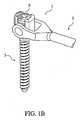
図1Aおよび図1Bに示すように、単一ユニットのアーム2と基部3とから構成されるねじ組立体1を提供する。このねじ組立体1は細長く、またねじ組立体1のアーム2と基部3とは、相互連結手段4によって連結されている。さらに、図1Aおよび図1Bに示すように、アーム2が基部3の長手方向軸と平行な第1の位置(図1Aに示す)に配置可能となりかつ基部3の長手方向軸に垂直な第2の位置(図1Bに示す)に配置可能となるように、相互連結手段4によってアーム2と基部3との間の動きが促進される。ねじ組立体1の基部3は、ある構造物(例えば骨)への取り付け用に構成され、アーム2は、支持構造体10(以下に詳細に説明する)への取り付け用に構成されている。適用の際には、1つまたはそれ以上のねじ組立体1が、支持構造体10(図示せず)に取り付けられる。2つのねじ組立体1が1つの支持構造体10に取り付けられるのが好ましい。(Detailed explanation)
As shown in FIGS. 1A and 1B, a
代替的なねじ組立体1の実施形態では、ねじ組立体1のアーム2と基部3は、形状記憶金属の1つの連続片として形成されている。この実施形態では、相互連結手段4が形状記憶金属から構成されており、該形状記憶金属が、該形状記憶金属の形状(図示せず)に影響を及ぼすあらかじめ設定された条件に応じて、基部3に対するアーム2の動きを促進することができる。別の代替的なねじ組立体1の実施形態では、ねじ組立体1のアーム2と基部3は、1つの連続片として形成されており、アーム2と基部3との間の相互連結手段4は、曲げに適した材料から構成されている(図示せず)。 In an
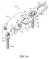
図1Aに示すように、いくつかの実施形態では、ねじ組立体1のアーム2の形状構成は、本体17と、基部ヨーク18とコネクタ端部12とからなる。アーム2の本体17は、用途に応じて形状および長さが異なることができる。一実施形態では、アーム2の本体17は、棒状(図1Aおよび図1B参照)である。あるいは、アーム2の本体17は、ねじ組立体1を操作するためのねじ組立体用工具内に実質的に嵌合するような形状となっている。そのようなねじ組立体用工具19の一例を図7に示す。 As shown in FIG. 1A, in some embodiments, the configuration of the
ねじ組立体1は、チタン、ステンレス鋼、炭素繊維、生体適合性材料等を含む、耐久性を有し、かつ身体内に植え込むことができる数多くの材料で製造することができる。一実施形態では、ねじ組立体1は、チタンで製造されている。さらに、ねじ組立体1は、再吸収性材料または形状記憶金属で製造することができる。あるいは、ねじ組立体1は、上記の材料のいずれかの複合物または組み合わせであってもよい。ねじ組立体1の寸法は、用途に応じて変わる。一般に、ねじ組立体1の長さは、0.1センチメートルから100センチメートルである。一実施形態では、その長さは、概ね50ミリメートルから600ミリメートルの間にある。別の実施形態では、ねじ組立体1は、脊柱28(図3B参照)の後部の支持を含む用途に対する寸法を有する。 The
図1Aに示すように、ねじ組立体1の基部3は、基部ヘッド20と固定具14とから構成される。固定具14は、ねじ、ステープル、フックまたは釘とすることができ、骨固定用に一般的に用いられる種類のものとすることができる。一実施形態では、固定具14は、椎骨27の茎26(図1Aおよび図3B参照)内への挿入用の種類のねじである。 As shown in FIG. 1A, the
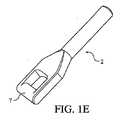
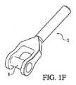
図1Cに示すように、図1Aのねじ組立体1の相互連結手段4は、圧入クロスピン式とすることができる。この実施形態では、基部ヘッド20は圧入クロスピン式ヘッド5であり、アーム2のヨーク18はピンホール25を含み、アーム2と基部3とは、圧入クロスピン(図示せず)および止めねじ9(図示せず)を含めてあらかじめ組み立てられている。図1D〜図1Fに示すような代替的実施形態では、図1Aの相互連結手段4は、連結横材を有する開放鞍型ヘッドとして形成されている。この実施形態では、基部ヘッド20は、相補的なアーム2の特徴に合わせてあらかじめ組み立てられた開放鞍型ヘッド6(図1Dに示す)として形成されている。図1Eに示すように、開放鞍型ヘッド6と相補的なアーム2の特徴は、継ぎ目のない一体に配置された横材7とすることができる。あるいは、図1Fに示すように、相補的なアーム2の特徴は、圧入クロスピン8としてもよい。 As shown in FIG. 1C, the interconnection means 4 of the
図1Aおよび図1Bに示すように、アーム2と基部3は、止めねじ9によって単一のユニットとして結合ことができ、その場合、相互連結手段4は、連結横材を有する圧入クロスピン型または開放鞍型ヘッドの形状を有する。いくつかの実施形態では、開放鞍型ヘッドは、止めねじ9を受けるようにねじが切ってある。 As shown in FIGS. 1A and 1B, the
さらに、図1Aおよび図1Bに示すように、止めねじ9は、アーム2を定位置に固定させることができる。アーム2を展開位置へ移動させる前には、止めねじ9は、所定の位置にゆるく取り付けられている。展開時に、基部3のねじ切りした開放鞍型ヘッド6(図1D参照)内に止めねじ9を締め込むことによって、基部3の長手方向軸に実質的に垂直な位置にアーム2を固定することができる。 Further, as shown in FIGS. 1A and 1B, the
一実施形態では、アーム2の位置の固定および単一のユニットとしてのアーム2と基部3の結合は、止めねじ9ではなく、カム(図示せず)を用いて達成することができる。止めねじ9の代わりにカムを使用する場合、アーム2の固定およびアーム2と基部3の結合は、類似の手段によって達成される。 In one embodiment, the fixing of the position of the
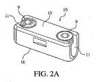
ここで図2A〜図2C、図3A、図3Bおよび図4を参照すると、ねじ組立体1のアーム2のコネクタ端部12を取り付けることができる支持構造体10が示されている(図3A、図3Bおよび図4参照)。図2Aに示すように、支持構造体10は、上面15と、下面16と、固定用の止めねじ9、または代替的実施形態ではカムを含む1つまたはそれ以上の端部が開放された鞍型受け部11とから構成される。受け部11は、ねじ組立体1のアーム2のコネクタ端部12を収容するような形状を有する。図2Aおよび図2Bに示すように、止めねじ9は、支持構造体10の上方から止めねじ9に容易にアクセスできるように、支持構造体10の上面15の平面に垂直に、支持構造体10内にねじ込まれている。一実施形態では、支持構造体10は、2つの受け部11から構成されており(図2A〜図2C、図3A、図3Bおよび図4参照)、これにより、支持構造体10を介して2つのねじ組立体1を結合することができる(図3A参照)。図3Bに示すような別の実施形態では、支持構造体10を介して結合した2つのねじ組立体1を脊柱28内の椎骨27の茎26内に植え込み、脊柱28の支持を行うことができる。 Referring now to FIGS. 2A-2C, 3A, 3B and 4, there is shown a
図2Bおよび図4に示すように、支持構造体10は、支持構造体10の上面15から支持構造体10の下面16まで貫通する中央開口部13をさらに含むように構成することができる。図2Bおよび図4に示すように、中央開口部13は、固定具14を収容するためにねじ切りをすることができ、任意選択的に、固定具14を所定の位置に固定するための止めねじ9またはカムを含むことができる。この実施形態では、中央開口部13のねじ切りと受け部11の(複数の)止めねじ9とは両方とも、支持構造体10の上面15に垂直に整列している。固定具14は、ねじ、ステープル、フックまたは釘とすることができ、骨固定用に一般的に用いられる種類のものとすることができる。一実施形態では、固定具14は、椎骨の茎内への挿入用の種類のねじである。 As shown in FIGS. 2B and 4, the
図2Cに示すような別の実施形態では、支持構造体10は、支持構造体10をある表面(例えば骨質構造物)上に固定するためのヒンジ式爪21を任意選択的に含むことができる。爪21は、支持構造体10内の2つの受け部11間に配置されたヒンジ22を特徴とする。爪21は、支持構造体10の上面15上方に延びるねじ切りした係合部材23を含んでおり、これにより、係合部材23にナット(図示せず)を嵌めると、ヒンジ22を中心とした枢動が生じ、爪21が閉じる。 In another embodiment, as shown in FIG. 2C, the
支持構造体10は、チタン、ステンレス鋼、炭素繊維、生体適合性材料等を含む、耐久性を有し、かつ体内に植え込むことができる数多くの材料で製造することができる。ねじ組立体1は、チタンで製造されるのが好ましい。さらに、支持構造体10は、再吸収性材料で製造することができる。あるいは、支持構造体10は、上記の材料のいずれかの複合物または組み合わせであってもよい。 The
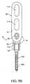
図5に示すように、本発明の別の実施形態は、受け部11、固定具14および固定手段を有する支持構造体10に連結された単一のねじ組立体1を含む。一実施形態では、受け部11は、開放鞍型ヘッド6として形成されている。別の実施形態では、支持構造体10は、複数の受け部11を含む。固定手段は、止めねじ9または代替的にカムを含むことができる。一実施形態では、ねじ組立体のアーム2のコネクタ端部12は、固定具が患者の体内に装着された後に、支持構造体10の開放鞍型受け部ヘッド6内に固定される。 As shown in FIG. 5, another embodiment of the present invention includes a
図6に示すように、本発明を用いて脊柱28を支持する方法は、1)脊柱28に沿って一連の小切開を加え、一連の椎骨27の茎26部分へのカニューレ29の接近手段を設けるステップと、2)カニューレ29の接近経路を用いて、2つの未展開のねじ組立体1を一連の茎26に送達し、次にそれらをそれぞれの茎26内にねじ込むステップ(ここで、未展開とは、各アームが基部の長手方向軸と平行な位置に配置されるようなねじ組立体の形状構成を指す)と、3)カニューレ29の接近経路および支持構造体用工具30を用いて、中央開口部、止めねじ、止めねじを有する2つの受け部および茎用ねじ式固定具を有する支持構造体10を送達し、所定の位置にねじ込んで固定するステップと、4)各ねじ組立体1のアームを基部の長手方向軸に実質的に垂直に展開するステップと、5)止めねじを用いて、各アームの各コネクタ端部を支持構造体10の受け部内に係合させて所定の位置に固定するステップとを含む。 As shown in FIG. 6, the method of supporting the
上記の方法は、ねじ組立体1の操作用の特殊なねじ組立体用工具19の使用を含む(図7参照)。ねじ組立体用工具19は、未展開ねじ組立体を内部に収容するように構成された内腔24を含む。使用時、このねじ組立体用工具19が、カニューレ29の範囲内からのある構造物(例えば骨)内への未展開ねじ組立体基部の挿入を促進する(図6参照)。 The method described above involves the use of a special
脊柱を支持するための本発明のさらに別の使用法は、1)アーム、基部および相互連結手段を有する2つのねじ組立体を骨に送達するステップと、2)ねじ組立体のアーム用の固定手段を有する2つの受け部を有する支持構造体を骨の近傍に送達するステップと、3)ねじ組立体のアームを展開するステップと、4)受け部の固定手段を係合させてねじ組立体のアームを支持構造体に固定するステップとを含むことができる。 Yet another use of the present invention for supporting the spinal column is: 1) delivering two screw assemblies having arms, bases and interconnecting means to the bone; and 2) securing the arms of the screw assemblies. Delivering a support structure having two receptacles with means to the vicinity of the bone; 3) deploying an arm of the screw assembly; and 4) engaging the fastening means of the receptacle to form a screw assembly. Securing the arm to the support structure.
脊柱を支持するための本発明の別の使用法は、1)アーム、基部および相互連結手段を有する2つのねじ組立体を骨に送達するステップと、2)固定手段と固定具とを備えた中央開口部、およびねじ組立体のアーム用の固定手段を有する2つの受け部を有する支持構造体を骨に送達するステップと、3)ねじ組立体のアームを展開するステップと、4)受け部の固定手段を係合させてねじ組立体のアームを支持構造体に固定するステップとを含むことができる。 Another use of the present invention for supporting the spinal column comprises 1) delivering two screw assemblies having arms, bases and interconnection means to the bone, and 2) fixing means and fixtures. Delivering a support structure to the bone having a central opening and two receivers having fixing means for the arms of the screw assembly; 3) deploying the arms of the screw assembly; and 4) the receiver. Engaging the securing means to secure the arm of the screw assembly to the support structure.
脊柱を支持するための本発明のさらに別の使用法は、1)アーム、基部および相互連結手段を有するねじ組立体を骨に送達するステップと、2)固定手段と固定具とを備える中央開口部、およびねじ組立体のアーム用の固定手段を有する支持構造体を骨に送達するステップと、3)ねじ組立体のアームを展開するステップと、4)受け部の固定手段を係合させてねじ組立体のアームを支持構造体に固定するステップとを含むことができる。 Yet another use of the present invention for supporting the spinal column is: 1) delivering a screw assembly having an arm, base and interconnection means to the bone; and 2) a central opening comprising a fixation means and a fixture. Delivering a support structure having a locking means for the arm and the arm of the screw assembly to the bone; 3) deploying the arm of the screw assembly; and 4) engaging the locking means of the receiving part. Securing the arm of the screw assembly to the support structure.
図8Aおよび図9Aに示すように、基部102と、1つまたはそれ以上の固定具組立体301を受けるように構成された支持体103と、基部102と支持体103との間の相互連結手段105とを備えるねじ組立体101を提供する。図8A、図8C、図8Dおよび図9A〜図9Eに示すように、支持体103は、上部107と下部108(図8B、図8C、図9Dおよび図9E参照)とを含む。相互連結手段105により、支持体103が基部102の長手方向軸と実質的に平行な第1の位置に配置可能となり(図8B、図9B〜図9D参照)、次いで基部102の長手方向軸に実質的に垂直に展開または配置する(図8A、図8C、図9Aおよび図9E参照)ことが可能となる。ねじ組立体101の基部102および1つまたはそれ以上の固定具組立体301は、患者の体内の構造物(例えば骨)への取り付け用に構成されている。適用に際しては、ねじ組立体101が1つまたはそれ以上の固定具組立体301を受け入れて、支持構造体106を形成する(図8Aおよび図9A参照)。一実施形態では、固定具組立体301は、支持体103の展開後にねじ組立体101と結合され(支持構造体106を形成し)、別の実施形態では、固定具組立体301は、ねじ組立体101と共にあらかじめ組み立てられている。先行技術の解決策に勝る本発明の1つの利点は、構造物を支持するための支持組立体106を使用する際の時間の節約である。別の利点は、除去の相対的容易性である。支持組立体106は、一時的植え込みに用いることも、永久的植え込みに用いることもできる。 As shown in FIGS. 8A and 9A, a
ひとたび組み立てれば、支持組立体106を用いて、骨質構造物を支持ことができる。支持される骨質構造物は、脚部の大腿骨または他の骨(例えば、脛骨および腓骨)、腕および手首の骨(例えば、上腕骨、橈骨および尺骨)、ならびに踵骨、骨盤、脊柱(椎骨)等のような他の骨を含むことができる。支持体は、単一の骨(すなわち、大腿骨、脛骨、上腕骨のような長骨)に対して施してもよく、1つより多い骨(すなわち、椎骨)に対して施してもよい。 Once assembled, the
ねじ組立体101は、チタン、ステンレス鋼、炭素繊維等を含む、耐久性を有し、かつ体内に植え込むことができる材料で製造することができる。一実施形態では、ねじ組立体101は、チタンで製造されている。別の実施形態では、ねじ組立体101は、生体適合性材料、再吸収性材料または上記の材料のいずれかの組み合わせで製造されている。ねじ組立体101の寸法は、用途に応じて変る。一般に、ねじ組立体101の長さは、20ミリメートルから1,000ミリメートルである。一実施形態では、その長さは、概ね50ミリメートルから400ミリメートルの間にある。別の実施形態では、ねじ組立体101は、脊柱後部(図示せず)の支持を含む用途に対する寸法を有する。 The
図8A〜図8C、図9A〜図9Eおよび図10A〜図10Bに示すように、ねじ組立体101の基部102は、ある形状および固定手段を有する基部ヘッド114と、固定具109aとから構成される。基部ヘッド114の形状は、支持体103を受けるかそれと相互連結するのに適したいくつかの形状のうちのいずれかから構成されることができる。一実施形態では、基部ヘッド114の形状は、開放鞍型ヘッドの形状である。図8A、図8Cおよび図9Aに示すように、一実施形態では、基部ヘッド114の固定手段は、止めねじ104とすることができる。止めねじ104は、基部102と支持体103との間における動きの自由を許容しながら支持体103と基部102を連結するように構成することができる(図8A、図9A、および図9E参照)。固定手段により、基部102に対するある位置に支持体103の固定を行うことができる。一実施形態では、止めねじ104を締め付けて、基部102(例えば、基部102の長手方向軸)に対するある位置に支持体103の固定を行うことができる。代替的実施形態では、基部ヘッド114の固定手段は、カム(図示せず)とすることができる。 As shown in FIGS. 8A to 8C, FIGS. 9A to 9E, and FIGS. 10A to 10B, the
図8A〜図8C、図9A〜図9Eおよび図10A〜図10Bに示すように、ねじ組立体101の固定具109aは、ねじ、ステープル、釘、フックおよびピンからなる群から選択することができる。一実施形態では、固定具109aは、骨固定用に構成されている。別の実施形態では、固定具109aは、椎骨の茎内への挿入用に構成されたねじである。 As shown in FIGS. 8A-8C, 9A-9E, and 10A-10B, the
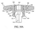
図8A、図9Aおよび図10A〜図10Bに示すように、固定具組立体301は、受け部306(以下に詳細に説明する)の形状に相互に連結するように構成されている。固定具組立体301の形状は、いくつかの形状のうちのいずれであってもよい。いくつかの実施形態では、支持体103と固定具組立体301との間の嵌め合わせは、2つの寸法(例えば、90度ねじり式受け部306を用いた場合)においてのみ生じる。図10A〜図10Bに示すように、固定具組立体301は、ヘッド302と、基部109bと、基部ヘッド114とから構成されることができる。固定具組立体301は、チタン、ステンレス鋼、炭素繊維等を含む、耐久性を有し、かつ体内に植え込むことができる数多くの材料から構成されることができる。さらに、固定具組立体301は、再吸収性材料または生体適合性材料、もしくは上記の材料のいずれかの組み合わせから構成されることができる。 As shown in FIGS. 8A, 9A, and 10A-10B, the
図10A〜図10Bに示すように、固定具組立体301は、固定具組立体301を支持体103に固定するための手段を含む。受け部306および固定具組立体301の相補的な(complimentary)ヘッド302がTスロット形状を有する図10Aに示すような一実施形態では、固定具組立体301を固定するための手段は、固定具組立体301のヘッド302にねじ込まれる止めねじ104とすることができ、この場合、ヘッド302は、ねじ切りした開口部305と変形可能な形状とを含む。固定具組立体301を支持体103に固定するためのそのような手段は、権利者の同じ米国特許出願第11/019,918号に開示されている。図10Bに示すように、止めねじ104がねじ切りした基部開口部305にねじ込まれる際に、変形可能なヘッド303が外方へ広がり、これにより、ヘッド302のTスロット形状が受け部306の平坦な内側面308に係合し、それに接触して動かなくなる。図10Aおよび図10Bに示すように、止めねじ104は、それがねじ切りした基部開口部305内に拘束されるように配置することができる。最終締め付け時に拘束した止めねじ104は、過拘束することが可能であり、それにより、変形可能なヘッド303は、外側へ広がるのを余儀なくされる。別の実施形態では、ヘッド302が受け部306の平坦な上面309または平坦な下面307もしくは両方にさらに係合し、固定を行うことができる。別の実施形態では、止めねじ104の代わりにカムを使用して、支持体103内への固定具組立体301の固定を行うことができる(図示せず)。 As shown in FIGS. 10A-10B, the
変形可能なねじ切りした基部開口部305の変形可能な形状は、固定具組立体301のヘッド302内の、腔、スロット、切り欠き、溝、切り抜き、すき間および陥凹部からなる群から選択される空洞から構成されることができる。一実施形態では、空洞は先細となっている。図9Aおよび図9Aに示すような別の実施形態では、固定具組立体301内の空洞は、ヘッド302に切り込まれたスロット313とすることができる。 The deformable shape of the deformable threaded
2004年4月16日に出願された、発明の名称「Subcutaneous Support」の米国特許出願第10/826,684号に開示されているものを含む、固定具組立体301を支持体103に固定するための他の手段が可能である。 Fixing
図10A〜図10Bに示すように、固定具組立体301は、ねじ切りした基部開口部305内に移動可能に配置された基部102を含む。基部102は、ねじ、ステープル、フックまたは釘とすることができ、一般にある構造物に(例えば骨に)固定するために用いられる種類のものとすることができる。一実施形態では、基部102は、椎骨茎内への挿入用の種類のねじである。別の実施形態では、基部102は、別の骨質構造物に取り付けることができる。 As shown in FIGS. 10A-10B, the
固定具組立体301への基部102の取り付けは、数多くの方法で達成することができる。一実施形態では、この取り付けは、基部102と固定具組立体301との間におけるヒンジ式の連結によって達成される(例えば、図1A〜図1Bにおいて見られるような連結を参照)。図10A〜図10Bに示すような別の実施形態では、この取り付けは、基部102上の多軸型基部ヘッド114と固定具組立体301ヘッド302内の相補的な(complimentary)レセプタクル304との間において行われる。 Attachment of the base 102 to the
固定具組立体301は、基部102を固定具組立体301のヘッド302内に固定するための手段をさらに含む。図10A〜図10Bに示すように、多軸型基部ヘッド114に対しては、固定手段は、ねじ切りした基部開口部305の内部に配置された止めねじ104を含むことができる。この構成では、止めねじ104を回すことによって、止めねじ104を基部102の多軸基部ヘッド114に直接圧着させ、それによりそれを固定具組立体301のレセプタクル304に押し付けて固定を行う。あるいは、基部102がヒンジ式のものである場合、固定手段は、ねじ切りした基部開口部305の内部に配置された止めねじ104から構成されることができる。この構成では、止めねじ104を回すことによって、止めねじ104をヒンジ式基部102の基部ヘッド114に直接圧着させ、それによりヒンジのピンに抗する摩擦を生成して固定を行う(図示せず)。別の実施形態では、止めねじ104の代わりにカムを用いて固定を行うことができる。 The
図10A〜図10Bに示すように、固定具組立体301の別の実施形態は、基部102と基部ヘッド114を通る長手方向開口部312と、工具接合部分311と、止めねじ開口部310とを含む。長手方向開口部312および止めねじ開口部310は、機器、ワイヤ(例えばKワイヤ)または他のガイドが固定具組立体301全体を通過することができるように構成されている。止めねじ開口部310はさらに、工具または機器が止めねじ開口部310を通過して基部102の工具接合部分311に係合することができるように構成されている。代替的に、止めねじ104をカムとしてもよい(図示せず)。 As shown in FIGS. 10A-10B, another embodiment of the
止めねじ開口部310は、任意の形状とすることができ、また止めねじ104の配置に影響を及ぼすことなく物体および工具の通過ならびに使用に適合する寸法を有することができる。 The set screw opening 310 can be of any shape and can have dimensions that are compatible with the passage and use of objects and tools without affecting the placement of the
長手方向開口部312は、限定するものではないが、円形、正方形、六角形、楕円形または任意の規則正しい形状もしくは不規則な形状を含む、任意の所望の断面形状を有することができる。 The
工具接合部分311は、基部102を操作する工具を受け入れるるのに適した任意の形状を有することができる。例えば、基部102がねじである場合、工具接合部分311は、六角形形状、または任意の他の一般に用いられるねじ頭用工具の接合部分の形状を有することができる。 The tool
固定具組立体301が図10A〜図10Bに示すように構成される場合、止めねじ104は、締め付けずに基部開口部305内にあらかじめ配置することができる。止めねじ開口部310および長手方向開口部312(基部102と基部ヘッド114を貫通する)により、固定具組立体301をあらかじめ組み立てた実施形態を通じたアクセスが可能となる。さらに、固定具組立体301があらかじめ組み立てられている場合、止めねじ開口部310を通じた基部ヘッド114の工具接合部分311へのアクセスが提供される。 When the
図8A、図8D、図9A、図9Dおよび図9Eに示すように、支持体103は、ある形状を有する。支持体103の形状は、ボード形、プレート形、細長い断面形、楕円形、正方形、I形および棒形からなる群から選択することができる。図8A、図8D、図9A、図9Dおよび図9Eに示すような一実施形態では、支持体は、プレートとして形づくられている。一実施形態では、支持体103の長さは、最小でも、2つまたはそれ以上の椎骨にまたがるのに必要な長さと実質的に同一である。一実施形態では、支持体103は、実質的に3つの椎骨にまたがるのに必要な長さを有する。別の実施形態では、支持体103の長さは、概ね25ミリメートルから140ミリメートルの間にある。 As shown in FIGS. 8A, 8D, 9A, 9D, and 9E, the
図8A〜図8Dに示すように、一実施形態では、支持体103は、コネクタ端部110と、1つまたはそれ以上の開口部111と、受け部306とから構成される。コネクタ端部110は、支持体103とねじ組立体101の基部102の相互連結用に構成されている。一実施形態では、コネクタ端部110は、支持体103とねじ組立体101の基部102とのヒンジ式相互連結用に構成されている。 As shown in FIGS. 8A-8D, in one embodiment, the
図8A、図8B、および図8Dに示すように、一実施形態では、支持体103の1つまたはそれ以上の開口部111は、支持体103に対して、コネクタ端部110の近位に配置された第1の開口部111cと、コネクタ端部110の遠位に配置された第2の開口部111aとを含む。図8A、図8B、および図8Dに示すように、第1の開口部111cは、支持体103に対する基部102のある範囲の動きに対して設けられている。一実施形態では、支持体103に対する基部102の動きは、ヒンジ式の動きを含む(図8A〜図8C参照)。図8Aに示すように、第2の開口部111aは、固定具組立体301が支持体103と共に組み立てられたときに、基部102および固定具組立体301を支持体103に固定するための手段へのアクセスを提供することができる。一実施形態では、第2の開口部111aは、支持体103が基部102に実質的に垂直な位置に展開された後に、上方からの支持体103へのアクセスを提供することができる。 As shown in FIGS. 8A, 8B, and 8D, in one embodiment, one or
図8Aおよび図8Dに示すように、一実施形態では、受け部306は、支持体103の長軸内に配置されている。別の実施形態では、受け部306は、支持体103の上部107または下部108に連結されている。さらに別の実施形態では、受け部306は、実質的に支持体103の全長にわたっている。受け部306の構造は、いくつかの設計および形状のうちのいずれかから構成されることができる。一実施形態では、受け部306は、スロット、溝、トラック、蟻形およびスナップイン構造からなる群から選択される構造を有する。別の実施形態では、受け部306は、90度ねじり込み構造を有する。さらに別の実施形態では、受け部306と固定具組立体301は両方とも、Tスロットを備える相互連結形状に構成されている(図10Aおよび図10B参照)。図10Aおよび図10Bに示すように、一実施形態では、受け部306のTスロット構造は、平坦な上面309と、平坦な下面307と、平坦な内側面308とから構成されることができる。受け部306は、一方または両方の端部が開放もしくは閉鎖された2つの端部を含むことができる(図示せず)。 As shown in FIGS. 8A and 8D, in one embodiment, the receiving
図9A〜図9Eに示すように、一実施形態では、支持体103は、支持部材202と、ヘッド組立体201と、相互連結手段105(例えば、スロット−フランジの組み合わせ)とから構成される。支持部材202は、上部107および下部108ならびに1つまたはそれ以上の開口部111を含むことができる(図9A〜図9E参照)。図9A〜図9Cに示すように、一実施形態では、支持部材202は、受け部306と、1つまたはそれ以上の開口部111とを含む。 As shown in FIGS. 9A-9E, in one embodiment, the
図9Aに示すように、一実施形態では、受け部306は、支持部材202の長軸内に配置されている。別の実施形態では、受け部306は、支持部材202の上部107または下部108に連結されている(例えば付属部品として)。さらに別の実施形態では、受け部306は、実質的に支持部材202の全長にまたがっている。受け部306の構造は、いくつかの設計および形状のうちのいずれかから構成されることができる。一実施形態では、受け部306は、スロット、溝、トラック、蟻形およびスナップイン構造からなる群から選択される構造を有する。別の実施形態では、受け部306は、90度ねじり込み構造を有する。さらに別の実施形態では、受け部306とヘッド組立体201は両方とも、Tスロットを備える相互連結形状に構成されている(図10Aおよび図10B参照)。図10Aおよび図10Bに示すように、一実施形態では、受け部306のTスロット構造は、平坦な上面309と、平坦な下面307と、平坦な内側面308とから構成されることができる。 As shown in FIG. 9A, in one embodiment, the receiving
受け部306は、第1の端部が開放され第2の端部が閉鎖された2つの端部を含むことができる(図示せず)。あるいは、両方の端部が開放されていても、両方の端部が閉鎖されていてもよい(図示せず)。 The receiving
図9A〜図9Cに示すように、一実施形態では、支持部材202の1つまたはそれ以上の開口部111は、固定具組立体301が通過可能でかつ支持部材202と固定可能に係合可能な第1の開口部111aを含む。支持部材202の上部107から支持部材202の下部108を通るアクセスを提供す第2の開口部111bが含まれていてもよい(図9A〜図9C参照)。図9Bおよび図9Cに示すように、第2の開口部111bは、ヘッド組立体201が支持部材202と相互に連結されたときに、支持体103のヘッド組立体201へのアクセスをも提供することができる。 As shown in FIGS. 9A-9C, in one embodiment, one or
図9A〜図9Cに示すように、一実施形態では、ヘッド組立体201は、支持部材202と基部102の両方と相互に連結するように構成されている。ヘッド組立体201は、コネクタ端部110と、開口部111cと、ヘッド組立体201を支持部材202に固定するための固定手段(例えばフランジ)とを含む。一実施形態では、支持部材202の受け部306とヘッド組立体201とは、Tスロットを備える相互連結形状に構成されている。ヘッド組立体201と支持部材202との間の相互連結形状により、ヘッド組立体201の長手方向軸に沿った、支持部材202の調整可能な配置(および/または固定)を行うことができる(図9Bおよび図9C参照)。図9Bに示すように、ヘッド組立体201は、ねじ組立体101の全長を短くするために、支持部材202の内部に縮めることができる。それと対照的に、図9Cに示すように、ヘッド組立体201は、ねじ組立体101の全長を長くするために、支持部材202に対して伸ばすことができる。 As shown in FIGS. 9A-9C, in one embodiment, the
ヘッド組立体201のコネクタ端部110は、支持体103とねじ組立体101の基部102との相互連結用に構成することができる。一実施形態では、コネクタ端部110は、支持体103とねじ組立体101の基部102とのヒンジ式相互連結用に構成されている(図9A〜図9E参照)。 The
図9A〜図9Cに示すように、ヘッド組立体の開口部111は、支持体103に対する基部102のある範囲の動きを支持する寸法構成を有することができる。これも図9A〜図9Cに示すように、ヘッド組立体201を支持部材202に固定するための固定手段は、ヘッド組立体201の内部に配置された止めねじ104から構成されることができる。使用に際しては、止めねじ104を回すことによって、止めねじ104と支持部材202との間の接触を生じさせることができ、それにより、ヘッド組立体201を支持部材202に固定するための手段がもたらされる。代替的に、別の実施形態では、ヘッド組立体201を支持部材202に固定するための固定手段は、カムから構成されることができる。 As shown in FIGS. 9A-9C, the
骨質構造物を支持するための本発明の使用法は、1)受け部、基部、相互連結手段、および固定手段を有する支持体を備えるねじ組立体を骨に送達するステップと、2)基部の長手方向軸に実質的に垂直に支持体を展開するステップと、3)基部および固定手段を有する1つまたはそれ以上の固定具組立体を、支持体に通して骨内に植え込むステップと、4)基部を固定具組立体のうちの1つまたはそれ以上の内部に固定するステップと、5)固定具組立体のうちの1つまたはそれ以上を支持体の受け部内に固定するステップと、6)ねじ組立体の固定手段を係合させて基部に対する支持体の位置を固定するステップとを含むことができる。 The use of the present invention for supporting a bony structure includes 1) delivering a screw assembly comprising a support having a receiver, a base, an interconnecting means, and a securing means to the bone; and 2) of the base Deploying the support substantially perpendicular to the longitudinal axis; 3) implanting one or more fastener assemblies having a base and fixation means through the support and into the bone; 6) securing the base within one or more of the fixture assemblies; 5) securing one or more of the fixture assemblies within the receiving portion of the support; ) Engaging the fixing means of the screw assembly to fix the position of the support relative to the base.
さらに別の実施形態では、上述の使用法は、支持体を骨に隣接してまたは脊柱に隣接して配置するステップを含むことができる。一実施形態では、上述の方法は、支持体を背部の皮下脂肪層と共に配置するステップを含むことができる。別の実施形態では、上述の方法は、支持体を身体の外部に配置するステップを含むことができる。 In yet another embodiment, the above-described usage can include placing the support adjacent to the bone or adjacent to the spinal column. In one embodiment, the method described above can include placing the support with a subcutaneous fat layer on the back. In another embodiment, the method described above can include placing the support external to the body.
骨質構造物を支持するための本発明の別の使用法は、1)受け部を有する支持部材と、コネクタ端部を有するヘッド組立体と、相互連結手段とを備える支持体と、基部と、相互連結手段と、固定手段とを備えるねじ組立体を骨に送達するステップと、2)支持体を基部の長手方向軸に実質的に垂直に展開するステップと、3)基部および固定手段を有する1つまたはそれ以上の固定具組立体を、支持体に通して骨内に植え込むステップと、4)基部を固定具組立体のうちの1つまたはそれ以上の内部に固定するステップと、5)固定具組立体のうちの1つまたはそれ以上を支持体の受け部内に固定するステップと、6)ヘッド組立体を支持部材内に固定するステップと、7)ねじ組立体の固定手段を係合させて、基部に対する支持体の位置を固定するステップとを含むことができる。 Another use of the present invention for supporting bony structures is: 1) a support member having a receptacle, a head assembly having a connector end, a support comprising interconnecting means, a base, Delivering a screw assembly comprising interconnecting means and securing means to the bone; 2) deploying the support substantially perpendicular to the longitudinal axis of the base; and 3) having the base and securing means. Implanting one or more fastener assemblies through the support and into the bone; 4) securing the base within one or more of the fastener assemblies; 5) Securing one or more of the fixture assemblies within the receiving portion of the support; 6) securing the head assembly within the support member; and 7) engaging the securing means of the screw assembly. Let the position of the support relative to the base It may include the steps of a constant.
一実施形態では、上述の使用法は、支持体を骨に隣接してまたは脊柱に隣接して配置するステップを含むことができる。一実施形態では、上述の使用法は、支持体を背部の皮下脂肪層と共に配置するステップを含むことができる。別の実施形態では、上述の使用法は、支持体を身体の外部に配置するステップを含むことができる。 In one embodiment, the above-described usage can include placing the support adjacent to the bone or adjacent to the spinal column. In one embodiment, the above-described usage can include placing the support with a subcutaneous fat layer on the back. In another embodiment, the above-described usage can include placing the support external to the body.
所望の椎間板スペーシングを行うための本発明の使用法は、1)受け部を有する支持体と、基部と、相互連結手段と、固定手段とを備えるねじ組立体を椎骨内に植え込むステップと、2)支持体を基部の長手方向軸に実質的に垂直に展開するステップと、3)基部および固定手段を有する1つまたはそれ以上の固定具組立体を、支持体に通して椎骨内に植え込むステップと、4)受け部内に固定されていない固定具組立体を、支持体の受け部と相互に連結するステップと、5)ねじ組立体の基部と固定具組立体の基部を、互いに対して圧迫または伸延する(例えば、装置を搭載した椎骨の平行移動を達成するために)ステップと、6)固定具組立体を支持体内に固定する(例えば、止めねじまたはカムを用いて)ステップと、7)ねじ組立体固定手段を用いて(例えば、止めねじまたはカムを用いて)、基部に対する支持体の位置を固定するステップとを含むことができる。 The use of the present invention to achieve the desired intervertebral disc spacing includes 1) implanting a screw assembly comprising a support having a receiver, a base, interconnection means, and fixation means into the vertebra; 2) deploying the support substantially perpendicular to the longitudinal axis of the base; and 3) implanting one or more fastener assemblies having the base and fixation means through the support and into the vertebrae. And 4) interconnecting a fastener assembly not secured within the receptacle with the receptacle of the support, and 5) connecting the base of the screw assembly and the base of the fixture assembly relative to each other. Compressing or distracting (eg, to achieve translation of the vertebra carrying the device), 6) securing the fixture assembly within the support (eg, using a set screw or cam), 7) Screw assembly Using the constant means (e.g., using a setscrew or cam) may include the step of fixing the position of the support relative to the base.
本明細書において使用する用語「装置を搭載した」は、ある構造物(例えば椎骨)と医療装置または医療機器との間の物理的連結を定義するものである。 As used herein, the term “equipped with a device” defines a physical connection between a structure (eg, a vertebra) and a medical device or device.
所望の脊柱の湾曲をもたらすための本発明の使用法は、1)受け部を有する支持体と、基部と、相互連結手段と、固定手段とを備えるねじ組立体を椎骨内に植え込むステップと、2)支持体を基部の長手方向軸に実質的に垂直に展開するステップと、3)基部および固定手段を有する1つまたはそれ以上の固定具組立体を、支持体に通して椎骨内に植え込むステップと、4)受け部内に固定されていない固定具組立体を、支持体の受け部と相互に連結するステップと、5)基部を互いに対して圧迫または伸延する(例えば、脊柱の前湾曲/後湾曲をもたらすために)ステップと、6)固定具組立体を支持体内に固定する(例えば、止めねじまたはカムを用いて)ステップと、7)ねじ組立体固定手段を用いて(例えば、止めねじまたはカムを用いて)、基部に対する支持体の位置を固定するステップとを含むことができる。 The use of the present invention to provide the desired spinal curvature includes: 1) implanting a screw assembly comprising a support having a receiver, a base, interconnection means, and fixation means into the vertebra; 2) deploying the support substantially perpendicular to the longitudinal axis of the base; and 3) implanting one or more fastener assemblies having the base and fixation means through the support and into the vertebrae. And 4) interconnecting a fastener assembly not secured within the receiver with the receiver of the support, and 5) compressing or distracting the bases relative to each other (e.g., precurvature of the spine / A step) (to provide postcurvature), 6) a step of fixing the fastener assembly in the support (eg using a set screw or cam), and 7) using a screw assembly fixing means (eg a stop). Screw or cam There are) may include the step of fixing the position of the support relative to the base.
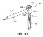
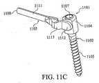
図11A〜図11Cおよび図11Eに示すように、単一ユニットの基部1102と1つまたはそれ以上のアーム1103とを含むねじ組立体1101を提供する。ねじ組立体1101のアーム1103と基部1102は、相互連結手段によって連結されている。ねじ組立体1101の基部1102は、ある構造物(例えば骨)への取り付け用に構成されており、アーム1103は、支持構造体(以下に詳細に説明する)への取り付け用に構成されている。適用時、1つまたはそれ以上のアーム1103を有するねじ組立体1101が1つまたはそれ以上の支持構造体に取り付けられ、支持組立体1301(図13Aおよび図13B参照)が形成される。支持組立体1301は、一時的植え込みに用いることも、永久的植え込み用に用いることもできる。 As shown in FIGS. 11A-11C and 11E, a
図11Aおよび図11Bに示すように、ねじ組立体1101の相互連結手段は、基部1102に対するアーム1103の自由回転(または多軸)運動を促進することができる。この相互連結手段は、限定するものではないが、ヒンジ手段、コレット手段、およびピンを含む任意の数の手段から選択することができる。図11Aおよび図11Bに示すように、相互連結手段は、基部1102の受け部1202内に配置された受け部端部1112を備える。この実施形態では、アーム1103は、基部ヘッド1104内の相補形状の受け部1202に連結された実質的に球状の受け部端部1112を有することができる。さらに、基部ヘッド1104は、閉鎖されていても、開放されていてもよい(例えば、図1Aに示すような開放鞍型に)。この相互連結手段によって促進されるアーム1103の自由回転運動は、実質的に、そのような運動の中心となる軸(以下「円錐軸」)を有する円錐形の範囲の運動となる。 As shown in FIGS. 11A and 11B, the interconnecting means of the
使用に際しては、図11Aおよび図11Bに示すような実施形態を用いて、患者の体内の構造物(例えば、一連の椎骨を有する脊柱)を支持することができる。支持される構造物が脊柱であり、かつ脊柱が長軸(以下「脊柱軸」)を含む場合、ねじ組立体1101は、該脊柱軸と実質的に共線的に脊柱を支持することができる。具体的には、ねじ組立体1101のアーム1103の運動の円錐軸は、任意選択的に、この円錐軸が実質的に脊柱軸と同一線上にあるように配置することができる。この配列は、ねじ組立体1101のアーム1103および基部1102を支持される構造物(例えば、一連の椎骨)と関連付けて配置する際に、ある程度の調節可能性を与える。例えば、3つの連続した椎骨が2つのアーム1103と2つの支持構造体(以下に詳細に説明する)を有するねじ組立体1101を含む支持組立体1301によって支持されることになる場合、3つの椎骨に対する3つの付着点を、実質的に同一線上に置くことができる。代案では、3つの付着点を必ずしも実質的に同一線上に置く必要はない。 In use, embodiments such as those shown in FIGS. 11A and 11B can be used to support structures within a patient's body (eg, a spinal column having a series of vertebrae). If the structure to be supported is a spinal column and the spinal column includes a long axis (hereinafter “vertebral axis”), the
図11Cおよび図11Eに示すような別の実施形態では、相互連結手段は、基部1102の基部ヘッド1104内に配置された1つまたはそれ以上のアーム1103の1つまたはそれ以上の受け部端部1112を備える。この実施形態では、アーム1103が基部1102の長手方向軸と平行な第1の位置(図11D、図12Bおよび図12Dに示す)に配置可能でかつ基部1102の長手方向軸に垂直な第2の位置(図11Cおよび図11Eに示す)に配置可能となるように、相互連結手段によってアーム1103と基部1102との間の動きを促進することができる。さらに、ねじ組立体1101の相互連結手段によって、基部1102に対するアーム1103の自由回転(または多軸)運動を促進することができる。上に述べたように、アーム1103の自由回転運動は、円錐軸を有する実質的に円錐状の範囲の運動とすることができる。使用に際しては、図11Cおよび図11Eに示すような実施形態を用いて、患者の体内の構造物(例えば、一連の椎骨を有する脊柱)を支持することができる。上述の実施形態に関して論じまた図面11Aおよび図11Bに示すように、本実施形態は、脊柱軸と実質的に共線的に脊柱を支持することができる。状況に応じて、図12Cおよび図12Dに示すように、脊柱軸と実質的に共線的に支持を行う実施形態は、円錐軸が脊柱軸に実質的に垂直となるように配置された、ねじ組立体1101のアーム1103の運動の円錐軸を含むことができる。この配列は、図11Cおよび図11Eに示す実施形態に関して上に述べたものと同程度のアーム1103の調節可能性および利点を提供する。 In another embodiment, such as shown in FIGS. 11C and 11E, the interconnecting means may include one or more receiving end portions of one or
ねじ組立体1101は、チタン、ステンレス鋼、炭素繊維等を含む、耐久性を有し、かつ体内に植え込むことができる材料で製造することができる。一実施形態では、ねじ組立体1101は、チタンで製造されている。別の実施形態では、ねじ組立体1101は、生体適合性材料、再吸収性材料、または上記の材料のいずれかの組み合わせで製造されている。ねじ組立体1101の寸法は、用途によって変わる。一般に、基部1102の長手方向軸と実質的に平行な第1の位置にアーム1103を配置可能な図11Cおよび図11Eに示すような実施形態では、ねじ組立体1101の長さは、概ね20ミリメートルから1,000ミリメートルである。一実施形態では、その長さは、概ね50ミリメートルから400ミリメートルの間にある。別の実施形態では、ねじ組立体1101は、複数レベルの脊柱後部の支持を含む用途に対する寸法を有する(図14参照)。図11Aおよび図11Bに示すような別の実施形態では、基部1102の長さは、概ね20ミリメートルから100ミリメートルであり、1つまたはそれ以上のアーム1103の長さは、概ね20ミリメートルから600ミリメートルである。別の実施形態では、基部1102の長さおよびアーム1103の長さは各々、概ね20ミリメートルから600ミリメートルの間にある。別の実施形態では、基部1102とアーム1103を組み合わせた長さは、複数レベルの脊柱後部の支持を含む用途に対する寸法を有する(図14参照)。 The
図11D、図12B、および図12Dに示すような一実施形態では、ねじ組立体1101は長手方向開口部1106を含む。この長手方向開口部1106は、ねじ組立体1101の全長にわたり、アーム1103が基部1102の長手方向軸と平行な第1の位置に配置されたときに、機器、工具、および、ガイド(例えばKワイヤ)の通過用の開口部となる(図11D、図12B、および図12D参照)。 In one embodiment as shown in FIGS. 11D, 12B, and 12D, the
図11A〜図11Cおよび図11Eに示すように、ねじ組立体1101の基部1102は、基部ヘッド1104と固定具1105とから構成される。固定具1105は、ねじ、ステープル、フックまたは釘とすることができ、骨固定用に一般的に用いられる種類のものとすることができる。一実施形態では、固定具1105は、椎骨の茎内への挿入用の種類のねじである(図11A〜図11C、図11E、図13A〜図13Bおよび図14参照)。 As shown in FIGS. 11A to 11C and FIG. 11E, the
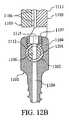
図12A〜図12Dに示すような一実施形態では、基部をアームに連結するための相互連結手段は、基部ヘッド1104から構成される。基部ヘッド1104は、ねじ組立体のアーム1103の受け部端部1112を受けるための受け部1202を含むことができる。別の実施形態では、基部ヘッド1104は、ヒンジ手段を用いた1つまたはそれ以上のねじ組立体のアーム1103のヒンジ式取り付け用に構成されている(例えば、図1A〜図1Bにおいて見られるようなものを参照)。 In one embodiment as shown in FIGS. 12A-12D, the interconnecting means for connecting the base to the arm comprises a
基部ヘッド1104は、固定手段を含むことができる。図11A〜図11Dおよび図12B〜図12Dに示すように、固定手段は、止めねじ1107とすることができる。基部ヘッド1104は、固定手段(例えば止めねじ1107)を収容するための開放鞍構造(図11Aおよび図11B参照)または閉鎖構造(図11C〜図11E参照)を含むように設計することができる。一実施形態では、固定手段は、ねじ組立体1101の基部1102と1つまたはそれ以上のアーム1103を共に固定する止めねじ1107である。 The
使用に際しては、基部1102と、1つまたはそれ以上のアーム1103と固定手段とを含むねじ組立体1101を、ある構造物への送達用にあらかじめ組み立てることができる。あるいは、ねじ組立体1101を、ある構造物の部位での組み立て用に別個の部品として送達してもよい。 In use, a
図11A、図11B、図11Dおよび図12B〜図12Dに示すように、止めねじ1107を締め付けることにより、1つまたはそれ以上のアーム1103を、基部1102に対するある位置に固定することができる。図11Dおよび図12B〜図12Dに示すような一実施形態では、基部の長手方向軸と実質的に平行な第1の位置から基部1102の長手方向軸に実質的に垂直な第2の位置へねじ組立体1102の1つまたはそれ以上のアーム1103が展開された後に、止めねじ1107を締め付けて、1つまたはそれ以上のアーム1103を第2の位置に固定することができる。代替的実施形態では、止めねじ1107の代わりにカム(図示せず)を用いることができる。 As shown in FIGS. 11A, 11B, 11D, and 12B-12D, one or
図11Aに示すような、単一のアーム1103が基部1102に連結されている別の実施形態では、止めねじ1107を締め付けて、アーム1103をある位置に固定することができる。この実施形態では、アーム1103は、基部ヘッド1104内の相補形状の受け部1202に連結された、実質的に球状の受け部端部1112を有することができる。基部ヘッド1104は、閉鎖されていても、開放されていてもよい(例えば、図11Aに示すような開放鞍)。止めねじ1107を締め付けることによって、アーム1103の受け部端部1112を受け部1202に押し付けて圧迫する荷重を生成し、ある位置へのアーム1103の固定を行うことができる。図12Cに示すように、受け部1202は、実質的に球状のコレット式受け部とすることができる。そのような実施形態では、止めねじ1107を締め付けることによって、アーム1103の受け部端部1112を受け部1202に押し付けて圧迫する荷重が生成され、それによって受け部端部1112の周りの1つまたはそれ以上の変形可能なフィンガ1204が撓み、アーム1103がある位置に固定される(図12C参照)。 In another embodiment where a
2つのアーム1103が基部1102に連結された、図11Bに示すような別の実施形態では、止めねじ1107を締め付けて、両方のアーム1103をある位置に固定することができる。この実施形態では、第1のアーム1103は、実質的に球状のコレット式受け部端部1201を含むことができ、第2のアームは、受け部端部1201内で相互に連結するように構成された受け部端部1112を含むことができる(図12Cおよび図12D参照)。図12Cに示すように、止めねじ1107を締め付けることによって、第1のアーム1103の受け部端部1201を第2のアーム1103の受け部端部1112に押し付けて圧迫する荷重が生成され、それにより第2のアーム1103の受け部端部1112の周りの受け部端部1201の1つまたはそれ以上の変形可能なフィンガ1204を撓ませ、両方のアーム1103をある位置に同時に固定することができる。 In another embodiment, as shown in FIG. 11B, where two
第1のアーム1103の受け部端部1201および第2のアーム1103の受け部端部1112は、各アーム1103を基部ヘッド1104に対するある位置に段階的に固定するように構成することもできる。例えば、第1のアームの受け部端部1201は、最初の締め付けによって受け部端部1112を基部ヘッドの受け部1202に押し付けて圧迫する荷重を生成し、第2のアーム1103の自由回転運動に影響を及ぼすことなく第1のアーム1103をある位置に固定するように構成することができる。最後の締め付け時に、それによって生成された増大した荷重によって、第1のアーム1103の受け部端部1201を第2のアーム1103の受け部端部1112に押し付けて圧迫し、それにより第2のアーム1103の受け部端部1112の周りの受け部端部1201の1つまたはそれ以上の変形可能なフィンガ1204を撓ませ、第2のアーム1103をある位置に固定することができる。 The receiving
図11Dに示すような別の実施形態では、アーム1103の受け部端部1112を相補形状の受け部1202に押し付けて圧迫する荷重を生成することにより、止めねじ1107を締め付けて円筒状の受け部端部1112を有する単一のアーム1103の固定を行うことができる。 In another embodiment, as shown in FIG. 11D, the
第1のアーム1103が実質的に円筒状のコレット式受け部端部1201を含み、第2のアーム1103(図示せず)が該コレット式受け部端部1201内で相互連結するように構成された受け部端部1112を含む、図12Bに示すようなさらに別の実施形態では、止めねじ1107を締め付けて2つのアーム1103の固定を行うことができる。この実施形態では、止めねじ1107を締め付けることによって、第1のアーム1103の実質的に円筒状のコレット式受け部端部1201を受け部1202に押し付けて圧迫する荷重が生成され(図12B参照)、それにより第2のアーム1103の受け部端部1112の周りの1つまたはそれ以上の変形可能なフィンガ1204(図示せず)を撓ませて、両方のアーム1103をある位置に固定する。 The
第1のアーム1103が実質的に球状のコレット式受け部端部1201を含み、第2のアーム1103が該コレット式受け部端部1201内で相互連結するように構成された受け部端部1112を含む、図12Cおよび図12Dに示すようなさらに別の実施形態では、止めねじ1107を締め付けて、2つのアーム1103の固定を行うことができる。この実施形態では、止めねじ1107を締め付けることによって、第1のアーム1103の実質的に球状のコレット式受け部端部1201を受け部1202に押し付けて圧迫する荷重が生成され、それにより第2のアーム1103の受け部端部1112の周りの1つまたはそれ以上の変形可能なフィンガ1204を撓ませ、両方のアーム1103をある位置に固定する(図12C参照)。 The
図11D、図12B、および図12Dに示すような別の実施形態では、止めねじ1107は、止めねじ開口部1115を含む。この止めねじ開口部1115は、基部1102の長手方向開口部1106と実質的に一列に並ぶように構成することができ、それによりアーム1103の長手方向開口部1106と基部1102との間を通り抜けての通過が可能となる(上に述べたように)。 In another embodiment, such as shown in FIGS. 11D, 12B, and 12D, set
図11A〜図11D、および図13A〜図13Bに示すように、ねじ組立体1101の1つまたはそれ以上のアーム1103は、細長い形状を有し支持構造体1109への取り付け用のコネクタ端部1108を含む本体1111と、受け部端部1112とを含む。一実施形態では、アーム1103本体1111の細長い形状は、棒である。別の実施形態では、アーム1103本体1111の細長い形状は、実質的に長手方向に分割された棒である。別の実施形態では、アーム1103本体1111の細長い形状は、基部1102の長手方向軸と実質的に平行な第1の位置に配置された2つまたはそれ以上のアーム1103間の相互関係が適切となるように構成された形状である(図示せず)。例えば、適切な相互関係は、長手方向に分割された棒状から構成されることができる。 As shown in FIGS. 11A-11D and FIGS. 13A-13B, one or
図11C〜図11Eおよび図13A〜図13Bに示すような別の実施形態では、アーム1103本体1111の細長い形状は、オフセット部分1113を含む。オフセット部分1113は、1つまたはそれ以上のアーム1103が基部1102の長手方向軸と実質的に平行に配置されたときに、ねじ組立体1101が薄型となるように構成することができる(図11Dおよび図12B参照)。さらに、オフセット部分1113は、アーム1103が基部1102の長手方向軸と実質的に平行に配置されたときに、基部1102とアーム1103の本体1111を直線状に整列させることができる(図11Dおよび図12B参照)。 In another embodiment, as shown in FIGS. 11C-11E and FIGS. 13A-13B, the elongated shape of the
図11D、図12Bおよび図12Dに示すような別の実施形態では、アーム1103の本体1111は、長手方向開口部1106を含む。一実施形態では、長手方向開口部1106は、アーム1103の本体1111の全長を走るチャネルまたは溝である(図示せず)。さらに別の実施形態では、2つの相互に関連するアーム1103は、アーム1103を相互に関連付けたときに一列に並んで単一の長手方向開口部1106を形成する長手方向開口部1106を有することができる。アーム1103本体の1111の長手方向開口部1106は、ねじ組立体1101の基部1102の長手方向開口部1106と同軸上に整列させることができる。長手方向開口部1106は、ねじ組立体1101の全長にわたり、機器、工具およびガイド(例えばKワイヤ)の通過用の開口部となる。 In another embodiment as shown in FIGS. 11D, 12B, and 12D, the
1つまたはそれ以上のアーム1103の受け部端部1112は、例えば図11A〜図11Bに示すような、基部ヘッド1104とのヒンジ式相互連結用のヒンジ手段を含むことができる。そのような実施形態では、固定手段を備えることができ、それによって、展開後、1つまたはそれ以上のアーム1103を基部1102の長手方向軸に実質的に垂直な位置に固定することが可能となる。そのような固定手段の一例は、ワンウェイラチェット構造とすることができる(図示せず)。 The receiving
別の実施形態では、単一のアーム1103の受け部端部1112は、基部ヘッド1104の受け部1202内での相互連結用の円筒形状を有することができる。そのような実施形態では、受け部1202は、アーム1103の受け部端部1112が中に受け入れられる開口部とすることができる。 In another embodiment, the
別の実施形態では、2つのアーム1103の受け部端部1112は、相互に連結して基部ヘッド1104内に配置することができる。例えば、受け部端部1112は、コレット式設計によって相互に連結することができる。第1の例では、2つの相互に連結する受け部端部1112は、実質的に円筒状の陥凹部、1つまたはそれ以上のリリーフカット1203および1つまたはそれ以上の変形可能なフィンガ1204を有する第1のコレット式受け部端部1201と、コレット式受け部端部1201の円筒状陥凹部内に嵌合するように構成された第2の固い円筒状の受け部端部1112とを含む、円筒状のコレット式設計を有することができる(図示せず)。 In another embodiment, the receiving
図11A、図11B、図12Cおよび図12Dに示すような第2の例では、2つの相互に連結する受け部端部1112は、実質的に球状の陥凹部、1つまたはそれ以上のリリーフカット1203および1つまたはそれ以上の変形可能なフィンガ1204を有する第1のコレット式受け部端部1201と、第1のコレット式受け部端部1201内に嵌合するように構成された第2の固い球状の受け部端部1112とを含む、球状のコレット式設計を有することができる。 In a second example, as shown in FIGS. 11A, 11B, 12C, and 12D, two interconnecting receiver ends 1112 have a substantially spherical recess, one or more relief cuts. A first collet-receiving
さらに、円筒状コレット式設計を示す図12Aおよび図12B、ならびに球状コレット式設計を示す図12Cおよび図12Dに示すように、それぞれの受け部端部1112が、相互に連結した受け部端部1112を貫通する長手方向開口部1106を含むことができる。そのような長手方向開口部1106は、アーム1103が基部1102の長手方向軸と実質的に平行に配置されたときに、基部1102の長手方向開口部1106と同軸上に整列するように構成することができる(図12Bおよび図12D参照)。 Further, as shown in FIGS. 12A and 12B showing a cylindrical collet design and FIGS. 12C and 12D showing a spherical collet design, each receiving
図11A〜図11D、図13Aおよび図13Bに示すように、1つまたはそれ以上のアーム1103のコネクタ端部1108は、支持構造体1109への取り付け用に構成されている。図13Aおよび図13Bに示すように、1つまたはそれ以上の支持構造体1109をねじ組立体1101に取り付けて、支持組立体1301を準備することができる。一実施形態では、各支持構造体1109が、固定具1105と、開口部1110と、固定手段とから構成される(図13Aおよび図13B参照)。1つまたはそれ以上の支持構造体1109は、チタン、ステンレス鋼、炭素繊維等を含む、耐久性を有し、かつ体内に植え込むことができる材料で製造することができる。一実施形態では、1つまたはそれ以上の支持構造体1109は、チタンで製造されている。別の実施形態では、1つまたはそれ以上の支持構造体1109は、生体適合性材料、再吸収性材料、または上記の材料のいずれかの組み合わせで製造されている。 As shown in FIGS. 11A-11D, 13A, and 13B, the
一実施形態では、各支持構造体1109は、患者の体内の構造物(例えば骨)への取り付け用に構成されている。図13Aおよび図13Bに示すように、1つまたはそれ以上の支持構造体1109用の固定手段は、止めねじ1107とすることができる。代替的に、固定手段は、カム(図示せず)であってもよい。 In one embodiment, each
図14に示すように、2つの支持構造体1109をねじ組立体1101に取り付けて、脊柱1401内の椎骨1402の茎1403内に植え込むことができる支持組立体1301を準備し、脊柱1401を支持することができる。別の実施形態では、単一の支持構造体1109をねじ組立体1101に取り付けて、脊柱1401内の椎骨1402の茎1403内に植え込むことができる支持組立体1301を準備し、脊柱1401を支持することができる。 As shown in FIG. 14, two
図13A、図13Bおよび図14を参照すると、本発明を用いて脊柱1401を支持する方法は、1)1つまたはそれ以上のアーム1103、基部1102および相互連結手段(例えば、1つまたはそれ以上のアーム1103の受け部端部1112と相互に連結された基部ヘッドの受け部1202)を有するねじ組立体1101を骨に送達するステップと、2)開口部1110およびねじ組立体1101のアーム1103のコネクタ端部1108用の固定手段を有する1つまたはそれ以上の支持構造体1109を傍らに位置する骨に送達するステップと、3)ねじ組立体1101の1つまたはそれ以上のアーム1103を傍らに位置する支持構造体1109に向けて展開するステップと、4)ねじ組立体1101の1つまたはそれ以上のアーム1103を所望の位置に固定するステップと、5)支持構造体1109の開口部1110の固定手段を係合させるステップとを含む。一実施形態では、1つまたはそれ以上の傍らに位置する支持構造体1109を、例えば、ねじ組立体1101を送達した椎体の片側または両側の1つまたはそれ以上の椎体を含む骨に送達することができる。別の実施形態では、1つまたはそれ以上の傍らに位置する支持構造体1109が、ねじ組立体1101を送達した椎体に隣接する椎体に送達される。別の実施形態では、傍らに位置する支持構造体1109のうちの1つまたはそれ以上が、最隣接椎体より遠位の椎体に送達される。 Referring to FIGS. 13A, 13B and 14, the method of supporting the
脊柱を支持する方法は、圧迫骨折セメント固定手技と併せて用いることもできる。圧迫骨折セメント固定は、椎体内に腔すなわち空洞を生成し、その後該腔に代用骨を充填して「内部鋳造物」を形成するための、バルーンカテーテルのような膨張可能な構造体の使用を含む経皮的手法である。代用骨は、限定するものではないが、同種移植組織または自己移植組織、ヒドロキシアパタイト、エポキシ、PMMA骨セメントまたは合成代用骨、医用グレードの焼き石膏もしくはリン酸カルシウムセメントあるいは硫酸カルシウムセメントを含む、整形外科に用いられる任意の適切な充填材とすることができるであろう。そのような治療に適した方法および機器は、米国特許第4,969,888号および第5,108,404号により完全に記載されている。圧迫骨折セメント固定は、椎骨の圧迫骨折を整復するためおよび骨を正確に移動させ、それによって椎体の正常な骨折前の解剖学的構造に近い状態を取り戻すために用いることができる。外傷(例えば、自動車事故または転倒による)によって引き起こされた椎骨の圧迫骨折は従来、後方アプローチを用いた観血的整復法、内固定安定化用金具類および癒合法によって治療されてきた。安定化用金具類は、骨折した椎体の負担を軽減し、骨移植片がすぐ隣に位置する1つの椎体と融合することができるように、椎間板をまたぐ動きを停止するために用いられ、安定化用金具類は通常、永久的移植片となる。外傷においては、安定化用金具類は、融合が生じた後の容易な除去を促進するように設計することができる。安定化用金具類は、本明細書に記載したものを含む多くの形態をとることができる。 The spinal support method can also be used in conjunction with a compression fracture cement fixation procedure. Compression fracture cement fixation uses an inflatable structure, such as a balloon catheter, to create a cavity or cavity in the vertebral body, which is then filled with a substitute bone to form an “inner cast” It is a transcutaneous technique including The bone substitute is orthopedic including, but not limited to, allograft tissue or autograft tissue, hydroxyapatite, epoxy, PMMA bone cement or synthetic bone substitute, medical grade calcined gypsum or calcium phosphate cement or calcium sulfate cement. It could be any suitable filler used. Methods and devices suitable for such treatment are fully described in US Pat. Nos. 4,969,888 and 5,108,404. Compression fracture cement fixation can be used to reduce the compression fracture of the vertebra and to move the bone accurately, thereby restoring the anatomical structure of the vertebral body prior to normal fracture. Vertebral compression fractures caused by trauma (eg, due to an automobile accident or a fall) have traditionally been treated by open reduction using a posterior approach, internal fixation stabilization hardware and fusion methods. Stabilizing brackets are used to reduce the strain on the fractured vertebral body and to stop the movement across the intervertebral disc so that the bone graft can be fused with one adjacent vertebral body. Stabilizing hardware is usually a permanent graft. In trauma, stabilization hardware can be designed to facilitate easy removal after fusion has occurred. Stabilization hardware can take many forms, including those described herein.
WiltseおよびSpencerによってSpine(1988)13(6):696−706に記載された、圧迫骨折セメント固定と天然の内筋平面を利用した安定化用金具類挿入の組み合わせによって、侵襲の少ない外科的療法を通じて患者治療の質を向上させる目標が達成される。 Less invasive surgical therapy by the combination of compression fracture cement fixation and stabilization brace insertion utilizing the natural internal muscle plane as described by Wiltse and Spencer in Spine (1988) 13 (6): 696-706 Through which the goal of improving the quality of patient care is achieved.
本発明のいくつかの好ましい実施形態を説明してきた。それでもなお、本発明の精神および範囲を逸脱することなく種々の変更を加えることができることが分かるであろう。例えば、ねじを用いて骨質構造物内に固定するいくつかの実施形態を説明してきたが、本発明の範囲は、それに限定されたものではない。カム、ねじ、ステープル、釘、ピン、またはフックのような任意の固定手段を用いることができる。従って、他の実施形態は、以下の特許請求の範囲内にある。 Several preferred embodiments of the present invention have been described. Nevertheless, it will be understood that various modifications can be made without departing from the spirit and scope of the invention. For example, although several embodiments have been described that use screws to secure within a bony structure, the scope of the present invention is not so limited. Any securing means such as cams, screws, staples, nails, pins or hooks can be used. Accordingly, other embodiments are within the scope of the following claims.
Claims (43)
Translated fromJapanese構造物を支持するように構成されたねじ組立体であって、前記ねじ組立体は、
基部と、
アームと、
前記アームを前記基部の長手方向軸と平行な第1の位置に配置可能とし、かつ前記基部の前記長手方向軸に垂直な第2の位置に配置可能とすることができる、前記基部を前記アームに連結するための相互連結手段と、
を含むねじ組立体を備え、
前記基部は、患者の体内の構造物への取り付け用に構成されている、
装置。A screw assembly configured to support a structure, the screw assembly comprising:
The base,
Arm,
The base can be disposed at a first position parallel to the longitudinal axis of the base and can be disposed at a second position perpendicular to the longitudinal axis of the base. Interconnecting means for connecting to,
A screw assembly including
The base is configured for attachment to a structure within a patient's body;
apparatus.
コネクタ端部と、
1つまたはそれ以上の開口部と、
受け部と、
から構成される、請求項2に記載の装置。The support is
A connector end;
One or more openings;
A receiver,
The apparatus of claim 2, comprising:
上部および下部を有する支持部材と、
ヘッド組立体と、
相互連結手段と、
から構成される、請求項1に記載の装置。The support is
A support member having an upper portion and a lower portion;
A head assembly;
Interconnection means;
The apparatus of claim 1, comprising:
受け部と、
1つまたはそれ以上の開口部と、
から構成される、請求項9に記載の装置。The support member is
A receiver,
One or more openings;
The apparatus of claim 9, comprising:
固定具組立体が貫通可能でかつ前記支持部材と固定可能に係合可能な第1の開口部と、
前記ヘッド組立体にアクセスするための前記支持部材の前記上部からのアクセスが提供された第2の開口部と、
を含む、請求項10に記載の装置。The one or more openings are
A first opening through which the fixture assembly can pass and engageably with the support member;
A second opening provided with access from the top of the support member for accessing the head assembly;
The apparatus of claim 10, comprising:
コネクタ端部と、
前記支持体に対する前記基部のある範囲の動きを支持する寸法構成を有する開口部と、
前記支持体に対する前記基部のある範囲の動きを支持する寸法構成を有するコネクタ端部近位開口部と、
前記ヘッド組立体を前記支持部材に固定するための固定手段と、
から構成され、前記ヘッド組立体は、前記支持部材との相互連結用に構成されている、請求項9に記載の装置。The head assembly is
A connector end;
An opening having a dimensional configuration to support a range of movement of the base relative to the support;
A connector end proximal opening having a dimension to support a range of movement of the base relative to the support;
Fixing means for fixing the head assembly to the support member;
10. The apparatus of claim 9, wherein the head assembly is configured for interconnection with the support member.
支持構造体であって、
固定具と、
受け部と、
固定手段と、
を含む支持構造体を備え、
前記固定具は、患者の体内の構造物への取り付け用に構成され、
前記受け部は、
前記ねじ組立体の前記アームへの取り付け用の開口部を有する受け部を含み、
前記固定手段は、前記支持構造体が患者の体内で展開された後に、前記アームを前記支持構造体に固定するように構成されている、
請求項13に記載の装置。further,
A support structure,
A fixture,
A receiver,
Fixing means;
Comprising a support structure comprising
The fixture is configured for attachment to a structure within a patient's body;
The receiving part is
A receiving portion having an opening for attaching the screw assembly to the arm;
The securing means is configured to secure the arm to the support structure after the support structure is deployed in a patient's body.
The apparatus of claim 13.
前記本体は、細長い形状を有し、かつ
支持構造体への取り付け用のコネクタ端部と、
前記相互連結手段の前記基部ヘッド受け部部分への連結用の受け部端部と、
を含む、請求項28に記載の装置。The two or more arms comprise a body;
The body has an elongated shape, and a connector end for attachment to a support structure;
A receiving end for connection to the base head receiving portion of the interconnection means;
30. The apparatus of claim 28, comprising:
前記オフセット部分は、前記アームが前記基部の長手方向軸と実質的に平行に配置されたときに、前記基部と前記アーム本体を直線状に整列させるように構成されている、請求項32に記載の装置。The elongated shape of the arm body includes an offset portion;
The offset portion is configured to linearly align the base and the arm body when the arm is disposed substantially parallel to the longitudinal axis of the base. Equipment.
1)受け部を有する支持体と、基部と、相互連結手段と、固定手段とを備える1つのねじ組立体を骨に送達するステップと、
2)前記基部の長手方向軸に実質的に垂直に前記支持体を展開するステップと、
3)基部および固定手段を有する1つまたはそれ以上の固定具組立体を、前記支持体に通して骨内に植え込むステップと、
4)前記固定具組立体のうちの1つまたはそれ以上の内部に前記基部を固定するステップと、
5)前記固定具組立体のうちの1つまたはそれ以上を前記支持体の受け部内に固定するステップと、
6)前記ねじ組立体の前記固定手段を係合させて、前記基部に対する前記支持体の位置を固定するステップと、
を含む方法。A method for supporting a bony structure, the method comprising:
1) delivering a screw assembly comprising a support having a receiver, a base, interconnection means, and fixation means to the bone;
2) deploying the support substantially perpendicular to the longitudinal axis of the base;
3) implanting one or more fastener assemblies having a base and fixation means through the support and into the bone;
4) securing the base within one or more of the fixture assemblies;
5) securing one or more of the fixture assemblies within a receiving portion of the support;
6) engaging the fixing means of the screw assembly to fix the position of the support relative to the base;
Including methods.
1)アーム、基部および相互連結手段を有する2つのねじ組立体を骨に送達するステップと、
2)前記ねじ組立体の前記アーム用の固定手段を有する2つの受け部を有する支持構造体を骨の近傍に送達するステップと、
3)前記ねじ組立体の前記アームを展開するステップと、
4)前記受け部の前記固定手段を係合させて、前記ねじ組立体の前記アームを前記支持構造体に固定するステップと、
を含む方法。A method of supporting the spinal column, the method comprising:
1) delivering two screw assemblies having arms, bases and interconnection means to the bone;
2) delivering a support structure having two receptacles having fixing means for the arm of the screw assembly to the vicinity of the bone;
3) deploying the arm of the screw assembly;
4) engaging the fixing means of the receiving portion to fix the arm of the screw assembly to the support structure;
Including methods.
1)2つまたはそれ以上のアーム、1つの基部および1つの相互連結手段を有する1つのねじ組立体を骨に送達するステップと、
2)前記ねじ組立体の前記アーム用の開口部および固定手段を有する1つまたはそれ以上の支持構造体を、傍らに位置する骨に送達するステップと、
3)前記ねじ組立体の前記2つまたはそれ以上のアームを、前記傍らに位置する支持構造体に向けて展開するステップと、
4)前記ねじ組立体の前記2つまたはそれ以上のアームを、所望の位置に固定するステップと、
5)前記支持構造体開口部の前記固定手段を係合させるステップと、
を含む方法。A method of supporting the spinal column, the method comprising:
1) delivering a screw assembly having two or more arms, a base and an interconnection means to the bone;
2) delivering one or more support structures having openings for the arms and securing means of the screw assembly to the bone located aside;
3) deploying the two or more arms of the screw assembly towards a support structure located beside it;
4) securing the two or more arms of the screw assembly in a desired position;
5) engaging the fixing means of the support structure opening;
Including methods.
Applications Claiming Priority (4)
| Application Number | Priority Date | Filing Date | Title |
|---|---|---|---|
| US10/825,962US7648520B2 (en) | 2004-04-16 | 2004-04-16 | Pedicle screw assembly |
| US11/027,501US7811311B2 (en) | 2004-12-30 | 2004-12-30 | Screw with deployable interlaced dual rods |
| US11/027,500US7789899B2 (en) | 2004-12-30 | 2004-12-30 | Bone anchorage screw with built-in hinged plate |
| PCT/US2005/012657WO2005104970A1 (en) | 2004-04-16 | 2005-04-15 | Screw assembly |
Publications (2)
| Publication Number | Publication Date |
|---|---|
| JP2007532258Atrue JP2007532258A (en) | 2007-11-15 |
| JP2007532258A5 JP2007532258A5 (en) | 2008-05-29 |
Family
ID=34965628
Family Applications (1)
| Application Number | Title | Priority Date | Filing Date |
|---|---|---|---|
| JP2007508524APendingJP2007532258A (en) | 2004-04-16 | 2005-04-15 | Screw assembly |
Country Status (5)
| Country | Link |
|---|---|
| EP (1) | EP1740112A1 (en) |
| JP (1) | JP2007532258A (en) |
| AU (1) | AU2005237459A1 (en) |
| CA (1) | CA2562744A1 (en) |
| WO (1) | WO2005104970A1 (en) |
Cited By (8)
| Publication number | Priority date | Publication date | Assignee | Title |
|---|---|---|---|---|
| JP2008519611A (en)* | 2004-11-09 | 2008-06-12 | デピュイ・スパイン・インコーポレイテッド | Minimally invasive spinal fixation guide system and method |
| JP2009533183A (en)* | 2006-04-11 | 2009-09-17 | ジンテス ゲゼルシャフト ミット ベシュレンクテル ハフツング | Minimally invasive fixation system |
| KR20110095930A (en)* | 2008-12-10 | 2011-08-25 | 컨셉트 스파인 리미티드 | Spinal malformation surgery device |
| US9808281B2 (en) | 2009-05-20 | 2017-11-07 | DePuy Synthes Products, Inc. | Patient-mounted retraction |
| US10098666B2 (en) | 2011-05-27 | 2018-10-16 | DePuy Synthes Products, Inc. | Minimally invasive spinal fixation system including vertebral alignment features |
| US10888360B2 (en) | 2010-04-23 | 2021-01-12 | DePuy Synthes Products, Inc. | Minimally invasive instrument set, devices, and related methods |
| KR20230102347A (en)* | 2021-12-30 | 2023-07-07 | 가톨릭대학교 산학협력단 | Spinal fixation device |
| US12440248B2 (en) | 2022-06-28 | 2025-10-14 | DePuy Synthes Products, Inc. | Minimally invasive instrument set, devices, and related methods |
Families Citing this family (8)
| Publication number | Priority date | Publication date | Assignee | Title |
|---|---|---|---|---|
| US7967826B2 (en) | 2003-10-21 | 2011-06-28 | Theken Spine, Llc | Connector transfer tool for internal structure stabilization systems |
| US7588575B2 (en) | 2003-10-21 | 2009-09-15 | Innovative Spinal Technologies | Extension for use with stabilization systems for internal structures |
| US7588588B2 (en) | 2003-10-21 | 2009-09-15 | Innovative Spinal Technologies | System and method for stabilizing of internal structures |
| WO2007138659A1 (en) | 2006-05-26 | 2007-12-06 | National University Corporation Nagoya University | External fixator |
| US7806913B2 (en) | 2006-08-16 | 2010-10-05 | Depuy Spine, Inc. | Modular multi-level spine stabilization system and method |
| NL1033910C1 (en)* | 2007-05-31 | 2008-12-02 | Baat Holding B V | Medical device for positioning bone parts, in particular spine, relative to each other, as well as a tool for fitting such a medical device component by component. |
| JP2010536533A (en)* | 2007-08-24 | 2010-12-02 | スピナル エレメンツ,インク. | Loop rod spinal fixation device |
| US9827013B2 (en) | 2009-12-08 | 2017-11-28 | Concept Spine Ltd. | Surgical device for correction of spinal deformities |
Citations (2)
| Publication number | Priority date | Publication date | Assignee | Title |
|---|---|---|---|---|
| US5649926A (en)* | 1994-07-14 | 1997-07-22 | Advanced Spine Fixation Systems, Inc. | Spinal segmental reduction derotational fixation system |
| JP2003526443A (en)* | 2000-03-15 | 2003-09-09 | エスディージーアイ・ホールディングス・インコーポレーテッド | Multi-directional pivoting bone screw and fixation system |
Family Cites Families (6)
| Publication number | Priority date | Publication date | Assignee | Title |
|---|---|---|---|---|
| DE9402695U1 (en)* | 1994-02-18 | 1994-04-14 | Kernforschungszentrum Karlsruhe Gmbh, 76133 Karlsruhe | Implant |
| JP2871620B2 (en)* | 1996-09-06 | 1999-03-17 | 株式会社ロバート・リード商会 | Bone fixation device |
| US7322979B2 (en)* | 2000-03-15 | 2008-01-29 | Warsaw Orthopedic, Inc. | Multidirectional pivoting bone screw and fixation system |
| US6802844B2 (en)* | 2001-03-26 | 2004-10-12 | Nuvasive, Inc | Spinal alignment apparatus and methods |
| US6520963B1 (en)* | 2001-08-13 | 2003-02-18 | Mckinley Lawrence M. | Vertebral alignment and fixation assembly |
| US20040210216A1 (en)* | 2003-04-17 | 2004-10-21 | Farris Robert A | Spinal fixation system and method |
- 2005
- 2005-04-15EPEP05735206Apatent/EP1740112A1/ennot_activeWithdrawn
- 2005-04-15JPJP2007508524Apatent/JP2007532258A/enactivePending
- 2005-04-15WOPCT/US2005/012657patent/WO2005104970A1/enactiveApplication Filing
- 2005-04-15AUAU2005237459Apatent/AU2005237459A1/ennot_activeAbandoned
- 2005-04-15CACA002562744Apatent/CA2562744A1/ennot_activeAbandoned
Patent Citations (2)
| Publication number | Priority date | Publication date | Assignee | Title |
|---|---|---|---|---|
| US5649926A (en)* | 1994-07-14 | 1997-07-22 | Advanced Spine Fixation Systems, Inc. | Spinal segmental reduction derotational fixation system |
| JP2003526443A (en)* | 2000-03-15 | 2003-09-09 | エスディージーアイ・ホールディングス・インコーポレーテッド | Multi-directional pivoting bone screw and fixation system |
Cited By (18)
| Publication number | Priority date | Publication date | Assignee | Title |
|---|---|---|---|---|
| US9179926B2 (en) | 2004-11-09 | 2015-11-10 | DePuy Synthes Products, Inc. | Minimally invasive spinal fixation guide systems and methods |
| JP2008519611A (en)* | 2004-11-09 | 2008-06-12 | デピュイ・スパイン・インコーポレイテッド | Minimally invasive spinal fixation guide system and method |
| US10441325B2 (en) | 2006-04-11 | 2019-10-15 | DePuy Synthes Products, Inc. | Minimally invasive fixation system |
| JP2009533183A (en)* | 2006-04-11 | 2009-09-17 | ジンテス ゲゼルシャフト ミット ベシュレンクテル ハフツング | Minimally invasive fixation system |
| KR20110095930A (en)* | 2008-12-10 | 2011-08-25 | 컨셉트 스파인 리미티드 | Spinal malformation surgery device |
| KR101648998B1 (en) | 2008-12-10 | 2016-08-17 | 컨셉트 스파인 리미티드 | Surgical device for the correction of spinal deformities |
| JP2012511365A (en)* | 2008-12-10 | 2012-05-24 | コンセプト スパイン リミテッド | Surgical device for correcting spinal deformities |
| US10993739B2 (en) | 2009-05-20 | 2021-05-04 | DePuy Synthes Products, Inc. | Patient-mounted retraction |
| US9808281B2 (en) | 2009-05-20 | 2017-11-07 | DePuy Synthes Products, Inc. | Patient-mounted retraction |
| US12349936B2 (en) | 2009-05-20 | 2025-07-08 | DePuy Synthes Products, Inc. | Patient-mounted retraction |
| US10888360B2 (en) | 2010-04-23 | 2021-01-12 | DePuy Synthes Products, Inc. | Minimally invasive instrument set, devices, and related methods |
| US11389213B2 (en) | 2010-04-23 | 2022-07-19 | DePuy Synthes Products, Inc. | Minimally invasive instrument set, devices, and related methods |
| US10098666B2 (en) | 2011-05-27 | 2018-10-16 | DePuy Synthes Products, Inc. | Minimally invasive spinal fixation system including vertebral alignment features |
| KR20230102347A (en)* | 2021-12-30 | 2023-07-07 | 가톨릭대학교 산학협력단 | Spinal fixation device |
| KR102653961B1 (en)* | 2021-12-30 | 2024-04-01 | 가톨릭대학교 산학협력단 | Spinal fixation device |
| KR20240046465A (en)* | 2021-12-30 | 2024-04-09 | 가톨릭대학교 산학협력단 | Spinal fixation device |
| KR102721002B1 (en)* | 2021-12-30 | 2024-10-22 | 가톨릭대학교 산학협력단 | Spinal fixation device |
| US12440248B2 (en) | 2022-06-28 | 2025-10-14 | DePuy Synthes Products, Inc. | Minimally invasive instrument set, devices, and related methods |
Also Published As
| Publication number | Publication date |
|---|---|
| CA2562744A1 (en) | 2005-11-10 |
| WO2005104970A1 (en) | 2005-11-10 |
| EP1740112A1 (en) | 2007-01-10 |
| AU2005237459A1 (en) | 2005-11-10 |
Similar Documents
| Publication | Publication Date | Title |
|---|---|---|
| US7811311B2 (en) | Screw with deployable interlaced dual rods | |
| US7789899B2 (en) | Bone anchorage screw with built-in hinged plate | |
| JP2007533377A (en) | Support for bone | |
| US10080590B2 (en) | Spinal stabilization system and methods of use | |
| US7648520B2 (en) | Pedicle screw assembly | |
| CN1972638A (en) | bone support | |
| EP2016918A1 (en) | Blocked plate with combined holes, stability control and double angulation, to join fractured bones | |
| US8518041B2 (en) | Modulus plating system | |
| US9592081B2 (en) | System and method for stabilizing a posterior fusion over motion segments | |
| US20170303973A1 (en) | Sleeve for bone fixation device | |
| US20050065520A1 (en) | Endosteal nail | |
| US10687861B2 (en) | Systems and methods for spinal compression, distraction, and fixation | |
| JP2007532258A (en) | Screw assembly | |
| KR20110055608A (en) | Pulpit spacer assembly | |
| JPH03503020A (en) | Fixation device for tubular bone fracture sites | |
| US7833247B2 (en) | Orthopedic clamps | |
| KR20070022042A (en) | Screw assembly | |
| HK1101117A (en) | Screw assembly | |
| HK1100059A (en) | Support for bone |
Legal Events
| Date | Code | Title | Description |
|---|---|---|---|
| A521 | Request for written amendment filed | Free format text:JAPANESE INTERMEDIATE CODE: A523 Effective date:20080411 | |
| A621 | Written request for application examination | Free format text:JAPANESE INTERMEDIATE CODE: A621 Effective date:20080411 | |
| A711 | Notification of change in applicant | Free format text:JAPANESE INTERMEDIATE CODE: A711 Effective date:20090625 | |
| A521 | Request for written amendment filed | Free format text:JAPANESE INTERMEDIATE CODE: A821 Effective date:20090625 | |
| A131 | Notification of reasons for refusal | Free format text:JAPANESE INTERMEDIATE CODE: A131 Effective date:20101018 | |
| A601 | Written request for extension of time | Free format text:JAPANESE INTERMEDIATE CODE: A601 Effective date:20110117 | |
| A602 | Written permission of extension of time | Free format text:JAPANESE INTERMEDIATE CODE: A602 Effective date:20110124 | |
| A601 | Written request for extension of time | Free format text:JAPANESE INTERMEDIATE CODE: A601 Effective date:20110218 | |
| A602 | Written permission of extension of time | Free format text:JAPANESE INTERMEDIATE CODE: A602 Effective date:20110225 | |
| A02 | Decision of refusal | Free format text:JAPANESE INTERMEDIATE CODE: A02 Effective date:20110706 |