JP2007526801A - Apparatus and method for facilitating tissue treatment with improved application of energy-based and non-energy-based modalities - Google Patents
Apparatus and method for facilitating tissue treatment with improved application of energy-based and non-energy-based modalitiesDownload PDFInfo
- Publication number
- JP2007526801A JP2007526801AJP2006551580AJP2006551580AJP2007526801AJP 2007526801 AJP2007526801 AJP 2007526801AJP 2006551580 AJP2006551580 AJP 2006551580AJP 2006551580 AJP2006551580 AJP 2006551580AJP 2007526801 AJP2007526801 AJP 2007526801A
- Authority
- JP
- Japan
- Prior art keywords
- endoscope
- treatment
- energy
- steerable
- ablation
- Prior art date
- Legal status (The legal status is an assumption and is not a legal conclusion. Google has not performed a legal analysis and makes no representation as to the accuracy of the status listed.)
- Granted
Links
- 238000000034methodMethods0.000titleclaimsabstractdescription161
- 238000011282treatmentMethods0.000titleclaimsdescription200
- 210000001519tissueAnatomy0.000claimsabstractdescription92
- 238000001356surgical procedureMethods0.000claimsabstractdescription30
- 210000004556brainAnatomy0.000claimsabstractdescription16
- 210000003200peritoneal cavityAnatomy0.000claimsabstractdescription11
- 210000000115thoracic cavityAnatomy0.000claimsabstractdescription11
- 238000002679ablationMethods0.000claimsdescription124
- 210000002216heartAnatomy0.000claimsdescription53
- 238000011298ablation treatmentMethods0.000claimsdescription31
- 208000003734Supraventricular TachycardiaDiseases0.000claimsdescription28
- 210000000056organAnatomy0.000claimsdescription27
- 210000003492pulmonary veinAnatomy0.000claimsdescription24
- 238000013507mappingMethods0.000claimsdescription20
- 230000001225therapeutic effectEffects0.000claimsdescription15
- 230000000747cardiac effectEffects0.000claimsdescription13
- 206010003658Atrial FibrillationDiseases0.000claimsdescription11
- 210000004185liverAnatomy0.000claimsdescription9
- 210000003625skullAnatomy0.000claimsdescription9
- 206010047302ventricular tachycardiaDiseases0.000claimsdescription9
- 230000000694effectsEffects0.000claimsdescription8
- 210000003484anatomyAnatomy0.000claimsdescription7
- 230000008859changeEffects0.000claimsdescription6
- 208000037265diseases, disorders, signs and symptomsDiseases0.000claimsdescription5
- 206010019280Heart failuresDiseases0.000claimsdescription4
- 239000000853adhesiveSubstances0.000claimsdescription4
- 230000001070adhesive effectEffects0.000claimsdescription4
- 230000003601intercostal effectEffects0.000claimsdescription4
- 230000005855radiationEffects0.000claimsdescription4
- 201000010099diseaseDiseases0.000claimsdescription3
- 238000013153catheter ablationMethods0.000claimsdescription2
- 238000001514detection methodMethods0.000claimsdescription2
- 210000003734kidneyAnatomy0.000claimsdescription2
- 210000003516pericardiumAnatomy0.000claimsdescription2
- 208000020446Cardiac diseaseDiseases0.000claims2
- 208000012902Nervous system diseaseDiseases0.000claims2
- 208000019622heart diseaseDiseases0.000claims2
- 208000025966Neurological diseaseDiseases0.000claims1
- 230000003213activating effectEffects0.000claims1
- 210000001072colonAnatomy0.000claims1
- 230000004064dysfunctionEffects0.000claims1
- 210000003709heart valveAnatomy0.000claims1
- 230000003239periodontal effectEffects0.000claims1
- 239000000126substanceSubstances0.000claims1
- 208000014001urinary system diseaseDiseases0.000claims1
- 210000000746body regionAnatomy0.000abstractdescription3
- 230000033001locomotionEffects0.000description36
- 238000003384imaging methodMethods0.000description13
- 238000002324minimally invasive surgeryMethods0.000description8
- 239000000835fiberSubstances0.000description7
- 238000005259measurementMethods0.000description7
- 229910001285shape-memory alloyInorganic materials0.000description7
- 210000005013brain tissueAnatomy0.000description6
- 230000006378damageEffects0.000description6
- 238000005286illuminationMethods0.000description6
- 210000004115mitral valveAnatomy0.000description6
- 210000005245right atriumAnatomy0.000description6
- 238000003491arrayMethods0.000description5
- 230000006870functionEffects0.000description5
- 210000005003heart tissueAnatomy0.000description5
- 238000003780insertionMethods0.000description5
- 230000037431insertionEffects0.000description5
- 238000002357laparoscopic surgeryMethods0.000description5
- 239000000463materialSubstances0.000description5
- 238000000926separation methodMethods0.000description5
- 239000000956alloySubstances0.000description4
- 210000003157atrial septumAnatomy0.000description4
- 230000005540biological transmissionEffects0.000description4
- 210000004204blood vesselAnatomy0.000description4
- 210000002837heart atriumAnatomy0.000description4
- 210000005246left atriumAnatomy0.000description4
- 210000004072lungAnatomy0.000description4
- 230000002685pulmonary effectEffects0.000description4
- 238000010317ablation therapyMethods0.000description3
- 210000004369bloodAnatomy0.000description3
- 239000008280bloodSubstances0.000description3
- 238000002591computed tomographyMethods0.000description3
- 238000005516engineering processMethods0.000description3
- 210000003128headAnatomy0.000description3
- 238000007917intracranial administrationMethods0.000description3
- 238000002560therapeutic procedureMethods0.000description3
- 210000002620vena cava superiorAnatomy0.000description3
- 230000002861ventricularEffects0.000description3
- 0CC1(*)CCCCC1Chemical compoundCC1(*)CCCCC10.000description2
- 210000000436anusAnatomy0.000description2
- 210000000709aortaAnatomy0.000description2
- 210000000988bone and boneAnatomy0.000description2
- 210000001175cerebrospinal fluidAnatomy0.000description2
- NEHMKBQYUWJMIP-UHFFFAOYSA-NchloromethaneChemical compoundClCNEHMKBQYUWJMIP-UHFFFAOYSA-N0.000description2
- 238000004891communicationMethods0.000description2
- 210000004351coronary vesselAnatomy0.000description2
- 238000007428craniotomyMethods0.000description2
- 230000009977dual effectEffects0.000description2
- 210000001035gastrointestinal tractAnatomy0.000description2
- 208000014674injuryDiseases0.000description2
- 230000003993interactionEffects0.000description2
- 230000003902lesionEffects0.000description2
- 230000003446memory effectEffects0.000description2
- 210000000653nervous systemAnatomy0.000description2
- 230000007935neutral effectEffects0.000description2
- 230000000399orthopedic effectEffects0.000description2
- 238000011084recoveryMethods0.000description2
- 239000000523sampleSubstances0.000description2
- 230000002459sustained effectEffects0.000description2
- 230000008733traumaEffects0.000description2
- 238000002604ultrasonographyMethods0.000description2
- 210000005166vasculatureAnatomy0.000description2
- 210000001631vena cava inferiorAnatomy0.000description2
- 208000024172Cardiovascular diseaseDiseases0.000description1
- 206010014561EmphysemaDiseases0.000description1
- 208000034693LacerationDiseases0.000description1
- 206010028980NeoplasmDiseases0.000description1
- 241000701811Reindeer papillomavirusSpecies0.000description1
- 208000002847Surgical WoundDiseases0.000description1
- 230000004913activationEffects0.000description1
- 238000013459approachMethods0.000description1
- 206010003119arrhythmiaDiseases0.000description1
- 230000006793arrhythmiaEffects0.000description1
- 238000013528artificial neural networkMethods0.000description1
- 230000000712assemblyEffects0.000description1
- 238000000429assemblyMethods0.000description1
- 230000001746atrial effectEffects0.000description1
- 238000010009beatingMethods0.000description1
- 238000001574biopsyMethods0.000description1
- 230000036760body temperatureEffects0.000description1
- 238000013276bronchoscopyMethods0.000description1
- 229940030602cardiac therapy drugDrugs0.000description1
- 210000000038chestAnatomy0.000description1
- 238000004140cleaningMethods0.000description1
- 238000002052colonoscopyMethods0.000description1
- 150000001875compoundsChemical class0.000description1
- 238000001816coolingMethods0.000description1
- 230000008878couplingEffects0.000description1
- 238000010168coupling processMethods0.000description1
- 238000005859coupling reactionMethods0.000description1
- 238000002059diagnostic imagingMethods0.000description1
- 238000002405diagnostic procedureMethods0.000description1
- 210000001951dura materAnatomy0.000description1
- 230000002526effect on cardiovascular systemEffects0.000description1
- 230000010102embolizationEffects0.000description1
- 238000001839endoscopyMethods0.000description1
- 238000002594fluoroscopyMethods0.000description1
- 239000000499gelSubstances0.000description1
- 210000001308heart ventricleAnatomy0.000description1
- 238000013152interventional procedureMethods0.000description1
- 230000001788irregularEffects0.000description1
- 230000002262irrigationEffects0.000description1
- 238000003973irrigationMethods0.000description1
- 208000037906ischaemic injuryDiseases0.000description1
- 210000005240left ventricleAnatomy0.000description1
- 230000004807localizationEffects0.000description1
- 238000002595magnetic resonance imagingMethods0.000description1
- 238000010297mechanical methods and processMethods0.000description1
- 230000007246mechanismEffects0.000description1
- 210000002418meningeAnatomy0.000description1
- 238000012978minimally invasive surgical procedureMethods0.000description1
- 230000004048modificationEffects0.000description1
- 238000012986modificationMethods0.000description1
- 210000003928nasal cavityAnatomy0.000description1
- 229910001000nickel titaniumInorganic materials0.000description1
- HLXZNVUGXRDIFK-UHFFFAOYSA-Nnickel titaniumChemical compound[Ti].[Ti].[Ti].[Ti].[Ti].[Ti].[Ti].[Ti].[Ti].[Ti].[Ti].[Ni].[Ni].[Ni].[Ni].[Ni].[Ni].[Ni].[Ni].[Ni].[Ni].[Ni].[Ni].[Ni].[Ni]HLXZNVUGXRDIFK-UHFFFAOYSA-N0.000description1
- 230000003287optical effectEffects0.000description1
- 238000005457optimizationMethods0.000description1
- 230000001575pathological effectEffects0.000description1
- 230000001766physiological effectEffects0.000description1
- 230000008569processEffects0.000description1
- 210000001147pulmonary arteryAnatomy0.000description1
- 238000007674radiofrequency ablationMethods0.000description1
- 210000005241right ventricleAnatomy0.000description1
- 210000004872soft tissueAnatomy0.000description1
- 210000001562sternumAnatomy0.000description1
- 210000002784stomachAnatomy0.000description1
- 210000002330subarachnoid spaceAnatomy0.000description1
- 230000000451tissue damageEffects0.000description1
- 231100000827tissue damageToxicity0.000description1
- 210000000591tricuspid valveAnatomy0.000description1
- 210000003932urinary bladderAnatomy0.000description1
- 230000000007visual effectEffects0.000description1
Images


Classifications
- A—HUMAN NECESSITIES
- A61—MEDICAL OR VETERINARY SCIENCE; HYGIENE
- A61B—DIAGNOSIS; SURGERY; IDENTIFICATION
- A61B1/00—Instruments for performing medical examinations of the interior of cavities or tubes of the body by visual or photographical inspection, e.g. endoscopes; Illuminating arrangements therefor
- A61B1/005—Flexible endoscopes
- A61B1/0051—Flexible endoscopes with controlled bending of insertion part
- A61B1/0055—Constructional details of insertion parts, e.g. vertebral elements
- A—HUMAN NECESSITIES
- A61—MEDICAL OR VETERINARY SCIENCE; HYGIENE
- A61B—DIAGNOSIS; SURGERY; IDENTIFICATION
- A61B1/00—Instruments for performing medical examinations of the interior of cavities or tubes of the body by visual or photographical inspection, e.g. endoscopes; Illuminating arrangements therefor
- A61B1/005—Flexible endoscopes
- A61B1/0051—Flexible endoscopes with controlled bending of insertion part
- A61B1/0052—Constructional details of control elements, e.g. handles
- A61B1/0053—Constructional details of control elements, e.g. handles using distributed actuators, e.g. artificial muscles
- A—HUMAN NECESSITIES
- A61—MEDICAL OR VETERINARY SCIENCE; HYGIENE
- A61B—DIAGNOSIS; SURGERY; IDENTIFICATION
- A61B1/00—Instruments for performing medical examinations of the interior of cavities or tubes of the body by visual or photographical inspection, e.g. endoscopes; Illuminating arrangements therefor
- A61B1/005—Flexible endoscopes
- A61B1/0058—Flexible endoscopes using shape-memory elements
- A—HUMAN NECESSITIES
- A61—MEDICAL OR VETERINARY SCIENCE; HYGIENE
- A61B—DIAGNOSIS; SURGERY; IDENTIFICATION
- A61B1/00—Instruments for performing medical examinations of the interior of cavities or tubes of the body by visual or photographical inspection, e.g. endoscopes; Illuminating arrangements therefor
- A61B1/012—Instruments for performing medical examinations of the interior of cavities or tubes of the body by visual or photographical inspection, e.g. endoscopes; Illuminating arrangements therefor characterised by internal passages or accessories therefor
- A61B1/0125—Endoscope within endoscope
- A—HUMAN NECESSITIES
- A61—MEDICAL OR VETERINARY SCIENCE; HYGIENE
- A61B—DIAGNOSIS; SURGERY; IDENTIFICATION
- A61B1/00—Instruments for performing medical examinations of the interior of cavities or tubes of the body by visual or photographical inspection, e.g. endoscopes; Illuminating arrangements therefor
- A61B1/012—Instruments for performing medical examinations of the interior of cavities or tubes of the body by visual or photographical inspection, e.g. endoscopes; Illuminating arrangements therefor characterised by internal passages or accessories therefor
- A61B1/018—Instruments for performing medical examinations of the interior of cavities or tubes of the body by visual or photographical inspection, e.g. endoscopes; Illuminating arrangements therefor characterised by internal passages or accessories therefor for receiving instruments
- A—HUMAN NECESSITIES
- A61—MEDICAL OR VETERINARY SCIENCE; HYGIENE
- A61B—DIAGNOSIS; SURGERY; IDENTIFICATION
- A61B1/00—Instruments for performing medical examinations of the interior of cavities or tubes of the body by visual or photographical inspection, e.g. endoscopes; Illuminating arrangements therefor
- A61B1/04—Instruments for performing medical examinations of the interior of cavities or tubes of the body by visual or photographical inspection, e.g. endoscopes; Illuminating arrangements therefor combined with photographic or television appliances
- A61B1/05—Instruments for performing medical examinations of the interior of cavities or tubes of the body by visual or photographical inspection, e.g. endoscopes; Illuminating arrangements therefor combined with photographic or television appliances characterised by the image sensor, e.g. camera, being in the distal end portion
- A—HUMAN NECESSITIES
- A61—MEDICAL OR VETERINARY SCIENCE; HYGIENE
- A61B—DIAGNOSIS; SURGERY; IDENTIFICATION
- A61B1/00—Instruments for performing medical examinations of the interior of cavities or tubes of the body by visual or photographical inspection, e.g. endoscopes; Illuminating arrangements therefor
- A61B1/31—Instruments for performing medical examinations of the interior of cavities or tubes of the body by visual or photographical inspection, e.g. endoscopes; Illuminating arrangements therefor for the rectum, e.g. proctoscopes, sigmoidoscopes, colonoscopes
- A—HUMAN NECESSITIES
- A61—MEDICAL OR VETERINARY SCIENCE; HYGIENE
- A61B—DIAGNOSIS; SURGERY; IDENTIFICATION
- A61B18/00—Surgical instruments, devices or methods for transferring non-mechanical forms of energy to or from the body
- A61B18/04—Surgical instruments, devices or methods for transferring non-mechanical forms of energy to or from the body by heating
- A61B18/12—Surgical instruments, devices or methods for transferring non-mechanical forms of energy to or from the body by heating by passing a current through the tissue to be heated, e.g. high-frequency current
- A61B18/14—Probes or electrodes therefor
- A61B18/1492—Probes or electrodes therefor having a flexible, catheter-like structure, e.g. for heart ablation
- G—PHYSICS
- G02—OPTICS
- G02B—OPTICAL ELEMENTS, SYSTEMS OR APPARATUS
- G02B23/00—Telescopes, e.g. binoculars; Periscopes; Instruments for viewing the inside of hollow bodies; Viewfinders; Optical aiming or sighting devices
- G02B23/24—Instruments or systems for viewing the inside of hollow bodies, e.g. fibrescopes
- G02B23/2407—Optical details
- G02B23/2461—Illumination
- G02B23/2469—Illumination using optical fibres
- G—PHYSICS
- G02—OPTICS
- G02B—OPTICAL ELEMENTS, SYSTEMS OR APPARATUS
- G02B23/00—Telescopes, e.g. binoculars; Periscopes; Instruments for viewing the inside of hollow bodies; Viewfinders; Optical aiming or sighting devices
- G02B23/24—Instruments or systems for viewing the inside of hollow bodies, e.g. fibrescopes
- G02B23/2476—Non-optical details, e.g. housings, mountings, supports
- G02B23/2484—Arrangements in relation to a camera or imaging device
- A—HUMAN NECESSITIES
- A61—MEDICAL OR VETERINARY SCIENCE; HYGIENE
- A61B—DIAGNOSIS; SURGERY; IDENTIFICATION
- A61B1/00—Instruments for performing medical examinations of the interior of cavities or tubes of the body by visual or photographical inspection, e.g. endoscopes; Illuminating arrangements therefor
- A61B1/005—Flexible endoscopes
- A61B1/0051—Flexible endoscopes with controlled bending of insertion part
- A61B1/0052—Constructional details of control elements, e.g. handles
- A—HUMAN NECESSITIES
- A61—MEDICAL OR VETERINARY SCIENCE; HYGIENE
- A61B—DIAGNOSIS; SURGERY; IDENTIFICATION
- A61B18/00—Surgical instruments, devices or methods for transferring non-mechanical forms of energy to or from the body
- A61B18/02—Surgical instruments, devices or methods for transferring non-mechanical forms of energy to or from the body by cooling, e.g. cryogenic techniques
- A—HUMAN NECESSITIES
- A61—MEDICAL OR VETERINARY SCIENCE; HYGIENE
- A61B—DIAGNOSIS; SURGERY; IDENTIFICATION
- A61B17/00—Surgical instruments, devices or methods
- A61B17/00234—Surgical instruments, devices or methods for minimally invasive surgery
- A61B2017/00292—Surgical instruments, devices or methods for minimally invasive surgery mounted on or guided by flexible, e.g. catheter-like, means
- A61B2017/00296—Surgical instruments, devices or methods for minimally invasive surgery mounted on or guided by flexible, e.g. catheter-like, means mounted on an endoscope
- A—HUMAN NECESSITIES
- A61—MEDICAL OR VETERINARY SCIENCE; HYGIENE
- A61B—DIAGNOSIS; SURGERY; IDENTIFICATION
- A61B17/00—Surgical instruments, devices or methods
- A61B17/00234—Surgical instruments, devices or methods for minimally invasive surgery
- A61B2017/00292—Surgical instruments, devices or methods for minimally invasive surgery mounted on or guided by flexible, e.g. catheter-like, means
- A61B2017/003—Steerable
- A—HUMAN NECESSITIES
- A61—MEDICAL OR VETERINARY SCIENCE; HYGIENE
- A61B—DIAGNOSIS; SURGERY; IDENTIFICATION
- A61B18/00—Surgical instruments, devices or methods for transferring non-mechanical forms of energy to or from the body
- A61B2018/00315—Surgical instruments, devices or methods for transferring non-mechanical forms of energy to or from the body for treatment of particular body parts
- A61B2018/00345—Vascular system
- A61B2018/00351—Heart
- A—HUMAN NECESSITIES
- A61—MEDICAL OR VETERINARY SCIENCE; HYGIENE
- A61B—DIAGNOSIS; SURGERY; IDENTIFICATION
- A61B18/00—Surgical instruments, devices or methods for transferring non-mechanical forms of energy to or from the body
- A61B2018/00315—Surgical instruments, devices or methods for transferring non-mechanical forms of energy to or from the body for treatment of particular body parts
- A61B2018/00434—Neural system
- A61B2018/00446—Brain
- A—HUMAN NECESSITIES
- A61—MEDICAL OR VETERINARY SCIENCE; HYGIENE
- A61B—DIAGNOSIS; SURGERY; IDENTIFICATION
- A61B18/00—Surgical instruments, devices or methods for transferring non-mechanical forms of energy to or from the body
- A61B18/02—Surgical instruments, devices or methods for transferring non-mechanical forms of energy to or from the body by cooling, e.g. cryogenic techniques
- A61B2018/0212—Surgical instruments, devices or methods for transferring non-mechanical forms of energy to or from the body by cooling, e.g. cryogenic techniques using an instrument inserted into a body lumen, e.g. catheter
- A—HUMAN NECESSITIES
- A61—MEDICAL OR VETERINARY SCIENCE; HYGIENE
- A61B—DIAGNOSIS; SURGERY; IDENTIFICATION
- A61B34/00—Computer-aided surgery; Manipulators or robots specially adapted for use in surgery
- A61B34/30—Surgical robots
- A61B2034/301—Surgical robots for introducing or steering flexible instruments inserted into the body, e.g. catheters or endoscopes
Landscapes
- Health & Medical Sciences (AREA)
- Life Sciences & Earth Sciences (AREA)
- Surgery (AREA)
- Physics & Mathematics (AREA)
- Engineering & Computer Science (AREA)
- Optics & Photonics (AREA)
- Medical Informatics (AREA)
- General Health & Medical Sciences (AREA)
- Veterinary Medicine (AREA)
- Public Health (AREA)
- Nuclear Medicine, Radiotherapy & Molecular Imaging (AREA)
- Animal Behavior & Ethology (AREA)
- Biomedical Technology (AREA)
- Heart & Thoracic Surgery (AREA)
- Molecular Biology (AREA)
- Biophysics (AREA)
- Radiology & Medical Imaging (AREA)
- Pathology (AREA)
- Astronomy & Astrophysics (AREA)
- General Physics & Mathematics (AREA)
- Cardiology (AREA)
- Plasma & Fusion (AREA)
- Otolaryngology (AREA)
- Multimedia (AREA)
- Endoscopes (AREA)
- Surgical Instruments (AREA)
- Instruments For Viewing The Inside Of Hollow Bodies (AREA)
- Electrotherapy Devices (AREA)
Abstract
Translated fromJapaneseDescription
Translated fromJapanese 本出願は、2004年1月28に出願された米国特許出願10/767,109号、及び、2002年8月26日に出願された米国特許出願10/228,583号の優先権を主張し、且つ、これらの両出願の一部継続出願である。米国特許出願10/228,583号は、2000年4月3日に出願された米国仮特許出願60/194,140号の優先権を主張する、2001年2月20日に出願された米国特許出願09/790,204号(現在は、米国特許第6,468,203号)の継続出願である。本出願は、これらの出願の各々の全てを援用して本文の記載の一部とする。 This application claims priority from US
本発明は、概して、内視鏡及び内視鏡的医療処置に関する。より詳細には、本発明は、従来の外科手術装置及び外科処置を用いては達することが困難な身体内の領域にアクセスし、且つ治療するための方法及び装置に関する。 The present invention relates generally to endoscopes and endoscopic medical procedures. More particularly, the present invention relates to methods and apparatus for accessing and treating regions within the body that are difficult to reach using conventional surgical devices and procedures.
多くの外科手術は、一般に、身体内の領域にアクセスするために大きい切開部を形成することを必要とする。例えば、心臓の後方領域又はその付近を手術することは、通常、開胸術を用いて行われる。このような処置は、概して、大掛かりな開胸手術又は胸骨切開を必要とし、これらは共に高侵襲性であり、多くの危険性、例えば、心臓の虚血性障害、塞栓の形成などを伴う。開胸術は、一般に、隣り合う肋骨間の肋間隙に切開を形成することを含み、胸骨切開は、「チェストスプレッダ」(chest spreader)法を含み、この方法は、概して最も侵襲的である。さらに、このような侵襲的な手術は深刻な罹病率を生じ、死亡率を増大させ、患者の回復時間を非常に長くする。 Many surgical procedures generally require making a large incision to access an area within the body. For example, surgery on or near the posterior region of the heart is usually performed using a thoracotomy. Such procedures generally require extensive thoracotomy or sternotomy, both of which are highly invasive and involve many risks, such as cardiac ischemic injury, embolization, and the like. Thoracotomy generally involves making an incision in the intercostal space between adjacent ribs, and the sternotomy includes a “chest spreader” method, which is generally the most invasive. In addition, such invasive surgery results in serious morbidity, increases mortality and greatly increases patient recovery time.
これに替わる外科的処置が低侵襲性の外科手術であり、この手術においては、患者の内部を目視及び手術するための様々な外科手術装置がアクセスできるように、患者の身体に小さい切開がつくられる。特別に設計された手術器具を用いてこれらの小さい切開を通り、身体内にアクセスし、手術を行うために、典型的に腹腔鏡が用いられる。これらの器具は、概して、外科医が患者の身体の外側から操作できるハンドルを有し、これにより外科医は、器具の操作を、一般的に、患者の身体内に入れられるチューブ、誘導器、又はトロカール装置内を通り抜ける細長い管状セクションを介して制御する。 An alternative surgical procedure is minimally invasive surgery, in which a small incision is made in the patient's body so that various surgical devices for viewing and operating inside the patient can be accessed. It is done. A laparoscope is typically used to access these surgical incisions through the small incisions with specially designed surgical instruments and access the body. These instruments generally have a handle that allows the surgeon to operate from outside the patient's body so that the surgeon can generally manipulate the instrument by a tube, inductor, or trocar that is placed within the patient's body. Control is through an elongated tubular section that passes through the device.
しかし、慣用の腹腔鏡術にも、適用可能性に或る程度限界がある。なぜなら、腹腔鏡用ツールの使用は「直線」(“straight-line”)を必要条件とするからである。この必要条件が、身体内の或る領域にアクセスすることを、不可能でないにしても非常に困難にしている。さらに、これらのツールに柔軟性が欠けていることが、身体内の或る領域へのアクセスを困難にしており、多くの外科医に、慣用の低侵襲性手術を用いさせずに開腹手術を選択させている。 However, the applicability of conventional laparoscopic surgery is limited to some extent. This is because the use of laparoscopic tools requires a “straight-line”. This requirement makes it very difficult, if not impossible, to access an area within the body. In addition, the lack of flexibility in these tools makes it difficult to access certain areas within the body, and many surgeons choose open surgery without using conventional minimally invasive surgery. I am letting.
低侵襲性の外科的処置にて身体内の領域へのアクセスをもたらすためには、柔軟な内視鏡装置も利用可能である。柔軟な内視鏡は、一般に、結腸鏡検査、気管支鏡検査、胸腔鏡検査、腹腔鏡検査及びビデオ内視鏡検査を含む様々な異なる診断法及びインターベンショナルな処置に用いられる。柔軟な内視鏡は、典型的に、光ファイバイメージングバンドル、又は、器具の先端に配置された小型カメラ、照明ファイバ、吸入又は洗浄のためにも用いられ得る1つ又は2つの器具チャネル、空気及び水用のチャネル及びバキュームチャネルを含み得る。しかし、内視鏡の操作のかなりの部分は、概して、装置を身体内で前進させることを必要とし、慣用の装置の使用を、より困難で時間がかかり、また合併症の可能性を増大させるものにしている。 Flexible endoscopic devices are also available to provide access to areas within the body with minimally invasive surgical procedures. Flexible endoscopes are commonly used for a variety of different diagnostic and interventional procedures, including colonoscopy, bronchoscopy, thoracoscopy, laparoscopy and video endoscopy. Flexible endoscopes are typically fiber optic imaging bundles, or small cameras placed at the tip of an instrument, illumination fibers, one or two instrument channels that can also be used for inhalation or cleaning, air And water channels and vacuum channels. However, a significant portion of endoscopic operation generally requires that the device be advanced within the body, making the use of conventional devices more difficult, time consuming, and increasing the potential for complications. I'm making things.
操縦可能な(steerable)柔軟な内視鏡が、身体の領域を通る適切な通路の選択を容易にするために考案されてきた。しかし、装置が身体内に、典型的により深く挿入されるにしたがって、装置が前進することが、概して、より困難になる。さらに、内視鏡の摩擦及び弛みが各ターンにて蓄積し、装置を前進及び後退させることを、より困難にする。別の問題は、例えば結腸鏡手術において生じ得るが、結腸鏡の長く細い管にループが形成されることである。このようなループは、内視鏡が障害物に遭遇し、狭い通路で行き詰り、又は、複合湾曲部を併合した形状を成すときに生じ得る。内視鏡は、前進せずに、患者の内部でループを形成する。結腸鏡の挿入を続行しようとすると、例えば、過剰な力が加えられて、患者の身体内の繊細な組織を損傷することがある。外科医は、問題の発生に気づかずに内視鏡の挿入を続行しようとすることがある。 Steerable flexible endoscopes have been devised to facilitate the selection of an appropriate passage through the body region. However, as the device is typically inserted deeper into the body, it generally becomes more difficult for the device to advance. In addition, endoscope friction and slack accumulates on each turn, making it more difficult to advance and retract the device. Another problem is that loops can form in the long and thin tubes of the colonoscope, which can occur, for example, in colonoscopic surgery. Such a loop may occur when the endoscope encounters an obstacle, gets stuck in a narrow passage, or forms a shape that merges compound bends. The endoscope does not advance but forms a loop inside the patient. Attempting to continue the insertion of the colonoscope may, for example, apply excessive force and damage sensitive tissue within the patient's body. The surgeon may attempt to continue the insertion of the endoscope without being aware of the problem.
ユーザは、内視鏡の遠位端から送信される画像を、視覚的画像装置を通して観察することができる。これらの画像から、及び、内視鏡が通った経路を知ることにより、ユーザは、通常、内視鏡の位置を決定することができる。しかし、患者の身体内での内視鏡の位置を極めて正確に決定することは困難である。 A user can observe an image transmitted from the distal end of the endoscope through a visual imaging device. From these images and knowing the path through which the endoscope has passed, the user can usually determine the position of the endoscope. However, it is difficult to determine the position of the endoscope within the patient's body very accurately.
以上に記載した器具のいずれもが、患者の身体内部に行われる外科手術の広範な要求条件を満たすために十分に柔軟ではない。さらに、上記の器具は、器具の遠位端を、管状セクションに対する任意の設定に十分に関節運動させるが、器具の長手方向軸を中心として遠位端を回転させることができない。この柔軟性の欠如により、外科医は、処置を行うために、器具を患者の身体に対して手動で回転及び移動させなくてはならない。 None of the instruments described above are sufficiently flexible to meet the broad requirements of surgery performed within a patient's body. In addition, the instrument described above fully articulates the distal end of the instrument for any setting relative to the tubular section, but cannot rotate the distal end about the longitudinal axis of the instrument. Due to this lack of flexibility, the surgeon must manually rotate and move the instrument relative to the patient's body in order to perform the procedure.
内視鏡装置は、以下に説明するように、身体内の様々な領域を治療することにおいて特に有用であり得る。このような内視鏡は、操縦可能な遠位部、及び、自動制御される近位部を含み得る。遠位部は、装置の操縦を容易にするために医師又は外科医により制御され、近位部は、例えば、コントローラ又はコンピュータにより自動制御され得る。操縦可能な内視鏡は、患者の身体内に、例えば、人体が元来有する身体内への開口の任意の1つを介して、例えば肛門を通して前進され得る。或いは、装置は、小さい切開を通して経皮的に身体内に挿入され得る。内視鏡装置が身体内に挿入されたならば、内視鏡装置は、患者の人体組織に影響を与えずに、器官、骨などの解剖学的特徴物への侵害を回避するように前進及び操縦され得る。このような装置の例は、以下の特許及び同時係属出願に詳細に記載されている。これらは、すなわち、米国特許第6,468,203号;米国特許第6,610,007号;2002年3月1日に出願された米国特許出願10/087,100号;2002年5月2日に出願された米国特許出願10/139,289号;2002年8月27日に出願された米国特許出願10/229,577号;2002年8月27日に出願された米国特許出願10/229,814号、及び、2002年11月27日に出願された米国特許出願10/306,580号であり、これらの特許及び特許出願の各々の全てを援用して本文の記載の一部とする。 Endoscopic devices can be particularly useful in treating various areas within the body, as described below. Such an endoscope may include a steerable distal portion and an automatically controlled proximal portion. The distal portion can be controlled by a physician or surgeon to facilitate maneuvering of the device, and the proximal portion can be automatically controlled by, for example, a controller or computer. The steerable endoscope can be advanced into the patient's body, for example, through the anus, via any one of the openings into the body that the human body originally has. Alternatively, the device can be inserted into the body percutaneously through a small incision. Once the endoscopic device has been inserted into the body, the endoscopic device will advance to avoid infringement of anatomical features such as organs, bones, etc. without affecting the patient's body tissue And can be maneuvered. Examples of such devices are described in detail in the following patents and co-pending applications. These are: US Pat. No. 6,468,203; US Pat. No. 6,610,007; US
このような装置を用いると、身体内の組織の閉塞領域を治療する1つの方法は、概して、細長い装置を身体内に、或る開口を通して前進させることを含み、この細長い装置は、近位部、及び、選択的に操縦可能な遠位部を有し、且つ、複数のセグメントを有する。この方法はまた、遠位部を、身体内の望ましい通路に沿った選択されたカーブを成すように選択的に操縦することを含み、この望ましい通路は、組織との接触を回避する(又は、隣接する組織が望ましい通路に沿って移動することを必要とせず、又は、隣接する組織に過剰な力が加えられることを回避する)。この方法はまた、装置の近位部を、遠位部の選択されたカーブを成すように制御しながら、細長い装置を身体内で、且つ、治療されるべき組織の領域に向って、さらに前進させることを含む。 With such a device, one method of treating an occluded region of tissue within the body generally includes advancing the elongate device into the body through an opening, the elongate device comprising a proximal portion And a selectively steerable distal portion and a plurality of segments. The method also includes selectively manipulating the distal portion to form a selected curve along a desired path in the body, the desired path avoiding contact with tissue (or Does not require adjacent tissue to move along the desired path, or avoids applying excessive force to adjacent tissue). The method also advances the elongate device further in the body and toward the area of tissue to be treated while controlling the proximal portion of the device to form a selected curve of the distal portion. Including.
制御可能な内視鏡装置の任意の1つを用いれば、従来の外科的技術を用いてはアクセス及び治療が一般的に困難な身体の様々な領域が、アクセス及び治療され得る。1つの治療例において、内視鏡装置は、神経系の外科手術に用いられ得る。内視鏡装置は、従来は到達することが困難な脳の領域にアクセスするための「直線」(“straight-line”)条件により制約されないため、且つ/又は、装置は、前進されるときにループを形成することを回避するため、内視鏡は、装置を脳の周囲にて、健康な脳組織に与える外傷が最小限又は無であるように操縦することにより、頭蓋内で正確に前進され、配置され得る。内視鏡は、また、必要に応じて、組織内の深部に埋まっている治療領域にアクセスするために、組織内を、付近の健康な組織へのどのような損傷も最小限にし得る通路を通って前進され得る。さらに、内視鏡装置は、脳上又は脳内の繊細な領域へのアクセスを可能にし得るので、従来の手術では、頭蓋骨の一部の取り外しを通常は必要とするような場合(例えば、開頭手術又は頭蓋内血種の治療など)にも、低侵襲性外科手術が行われ得る。さらに、鼻腔、又は、元来備わっている他の頭蓋穴を通してのアクセスも容易にされ得る。 With any one of the controllable endoscopic devices, various regions of the body that are generally difficult to access and treat using conventional surgical techniques can be accessed and treated. In one example of treatment, the endoscopic device may be used for nervous system surgery. Endoscopic devices are not constrained by “straight-line” conditions to access areas of the brain that are conventionally difficult to reach and / or when the device is advanced In order to avoid forming loops, the endoscope is accurately advanced within the skull by manipulating the device around the brain with minimal or no trauma to healthy brain tissue. And can be arranged. The endoscope also provides a path through the tissue that can minimize any damage to nearby healthy tissue, if necessary, to access treatment areas buried deep within the tissue. Can be advanced through. In addition, endoscopic devices may allow access to sensitive areas on or in the brain, so that conventional surgery usually requires removal of a portion of the skull (eg, craniotomy) Surgery or treatment of intracranial blood types, etc.) can also be performed with minimally invasive surgery. In addition, access through the nasal cavity or other natural skull holes may be facilitated.
内視鏡装置が用いられ得る別の治療分野は、冠動脈手術のための使用、例えば、僧帽弁の治療、心房細動の治療のための組織アブレーション、リードの配置、除去又は調節などを含み得る。一例において、内視鏡装置は、上大静脈を通して心臓内に挿入され、右心房内に前進され得る。内視鏡が右心房内に達したならば、遠位部が操縦されて心房中隔を通り、左心房に入ることができる。左心房にて、装置の遠位部が、治療される組織(この例では僧帽弁)付近に配置され得る。治療を行うために、治療に効果をもたらすための様々なツール又は装置、例えば、手術用メス、把持具などが、装置内の1又は複数の作業チャネルを通して配送され得る。 Other therapeutic areas in which endoscopic devices may be used include use for coronary surgery, such as treatment of mitral valves, tissue ablation for treatment of atrial fibrillation, lead placement, removal or adjustment, etc. obtain. In one example, the endoscopic device can be inserted into the heart through the superior vena cava and advanced into the right atrium. Once the endoscope has reached the right atrium, the distal portion can be steered through the atrial septum and into the left atrium. In the left atrium, the distal portion of the device can be placed near the tissue to be treated (in this example, the mitral valve). In order to perform a treatment, various tools or devices to effect the treatment, such as a scalpel, a gripper, etc., may be delivered through one or more working channels in the device.
内視鏡装置が用いられ得るさらに別の治療分野において、様々な胸腔鏡手術が、低侵襲性手術により、例えば経皮的に行われ得る。図示されているように、内視鏡は、患者の内部に、導入器、又はポートを介して前進され得る。ポートは、手術中に内視鏡のための固定された参照点を確立する基準点としても構成され得る。ポート又は基準点は、患者内での装置の位置を決定し且つ/又は維持するために用いられるコンピュータ又はプロセッサと電気通信し得る。内視鏡は、患者の身体内に、切開(例えば肋骨間の肋間隙に形成される)を通して前進され得る。次いで、内視鏡は胸腔内に前進され、操作されて、身体内の領域、例えば心臓の後方領域に達し得る。この領域は、直線的アクセスがないために、従来の腹腔鏡術では通常はアクセスできない In yet another therapeutic field where endoscopic devices can be used, various thoracoscopic procedures can be performed by minimally invasive surgery, for example percutaneously. As shown, the endoscope can be advanced into the patient via an introducer or port. The port can also be configured as a reference point that establishes a fixed reference point for the endoscope during surgery. The port or reference point may be in electrical communication with a computer or processor used to determine and / or maintain the position of the device within the patient. The endoscope may be advanced through the incision (eg, formed in the intercostal space between the ribs) into the patient's body. The endoscope can then be advanced into the thoracic cavity and manipulated to reach an area within the body, such as a posterior area of the heart. This area is not normally accessible with conventional laparoscopic surgery due to lack of linear access
本発明の一実施形態は、身体内での治療を容易にするための方法を提供する。この方法は、操縦可能な遠位端及び制御可能な近位端を有する内視鏡を挿入することを含み、制御可能な近位端は、操縦可能な遠位端に追従するように制御される。内視鏡は操作されて、身体内の或る位置に、或る身体部分の治療を容易にするために挿入される。治療が、この身体部分に行われる。この身体部分は、例えば、胸腔、頭蓋、又は腹膜腔にあり得る。 One embodiment of the present invention provides a method for facilitating treatment within the body. The method includes inserting an endoscope having a steerable distal end and a controllable proximal end, the controllable proximal end being controlled to follow the steerable distal end. The The endoscope is manipulated and inserted at a location within the body to facilitate treatment of a body part. Treatment is performed on this body part. This body part can be, for example, in the thoracic cavity, skull, or peritoneal cavity.
本発明の別の実施形態は、身体内の生理学的徴候に関する状態の治療を行うためのシステムを提供する。身体内の生理学的徴候を検知及び位置特定するためのシステムがある。身体内の生理学的徴候に関する、身体の一部の画像をもたらすためのシステムがある。操縦可能な内視鏡が、操縦可能な遠位端と、コンピュータコントローラの制御下で制御可能な近位端とを有し、コントローラは、検知するためのシステム、及び、画像をもたらすためのシステムから情報を受信する。 Another embodiment of the present invention provides a system for treating a condition related to physiological signs in the body. There are systems for detecting and locating physiological signs in the body. There are systems for producing images of parts of the body related to physiological signs in the body. A steerable endoscope has a steerable distal end and a proximal end controllable under the control of a computer controller, the controller comprising a system for sensing and a system for providing an image Receive information from.
本発明の別の実施形態は、心臓の治療を容易にするためのシステムを提供し、このシステムは、心臓の不良状態の位置を示すためのシステムを有する。また、位置を示すこのシステムにより発生される情報を用いるコントローラシステムも設けられる。このコントローラシステムは、発生された情報を用いることにより、操縦可能な遠位端、及び、操縦可能な遠位端に追従するように制御可能な近位端を有する操縦可能な内視鏡が、心臓の不良状態の治療を容易にするための位置へと関節運動することを補助する。さらに、心臓の不良状態の治療を行うための治療装置が、操縦可能な内視鏡によりもたらされて提供される。 Another embodiment of the present invention provides a system for facilitating treatment of the heart, the system having a system for indicating the location of a bad heart condition. A controller system is also provided that uses information generated by this system to indicate position. The controller system uses a generated information to provide a steerable endoscope having a steerable distal end and a proximal end controllable to follow the steerable distal end. Assists articulation to a position to facilitate treatment of a heart failure condition. In addition, a treatment device is provided provided by a steerable endoscope for treating a cardiac condition.
本発明の別の実施形態において、心臓のアブレーション治療を行うための、操縦可能な内視鏡を有する装置が提供され、この内視鏡は、操縦可能な遠位端と、操縦可能な遠位端の形状を自動的に追従するように構成された制御可能な近位端とを有する。アブレーション治療装置は、操縦可能な内視鏡により配備されるようになっている。固定具が、アブレーション治療装置の位置を固定する。 In another embodiment of the present invention, an apparatus is provided having a steerable endoscope for performing cardiac ablation therapy, the steerable distal end and a steerable distal end. A controllable proximal end configured to automatically follow the shape of the end. The ablation treatment device is adapted to be deployed by a steerable endoscope. A fixture fixes the position of the ablation treatment device.
本発明の別の実施形態は、身体内での治療を行う方法を提供し、この方法は、身体内での治療を容易にするために、内視鏡の操縦可能な遠位端を通路に沿って治療位置に前進させることにより行われる。内視鏡の近位端は、内視鏡の操縦可能な遠位端の経路に追従するように制御される。治療要素が治療位置にもたらされる。 Another embodiment of the present invention provides a method for performing a treatment within the body, the method comprising a steerable distal end of the endoscope in the passage to facilitate treatment within the body. Along the treatment position. The proximal end of the endoscope is controlled to follow the path of the steerable distal end of the endoscope. A therapeutic element is brought to the treatment location.
本発明の別の実施形態は、身体内に治療をもたらすために、1対の操縦可能な内視鏡を用いる。この内視鏡の対は、一方の内視鏡が他方の内視鏡内にあるように、或いは、一方の内視鏡が他方の内視鏡に隣接するように配置され得る。別の実施形態において、一方の操縦可能な内視鏡が、治療を容易にするための身体内の所望の位置に移動され、ついでこの位置に固定され得る。その後、第2の内視鏡が操作され、第1内視鏡によりもたらされた身体内の固定位置を用いて、治療を行い又は治療を容易にする。この手順は、例えば、拍動している心臓のような、運動している状態の治療に有用であり得、この場合、第1内視鏡が、第2内視鏡を用いるための固定された治療点として用いられ得る。 Another embodiment of the invention uses a pair of steerable endoscopes to provide treatment within the body. This pair of endoscopes can be arranged such that one endoscope is in the other endoscope or that one endoscope is adjacent to the other endoscope. In another embodiment, one steerable endoscope can be moved to a desired position in the body to facilitate treatment and then fixed in this position. Thereafter, the second endoscope is manipulated to perform treatment or facilitate treatment using the fixed position in the body provided by the first endoscope. This procedure may be useful in the treatment of a moving condition, such as a beating heart, in which case the first endoscope is fixed for use with the second endoscope. Can be used as a therapeutic point.
内視鏡装置は、また、腹膜腔内での処置のために用いられ得る。可能な用途は、泌尿器の、肥満体治療の、及び肝臓の手術のための低侵襲性手術を含み得る。また、脊髄手術又は整形外科手術の処置のための低侵襲性アクセスも達成され得る。このような処置において、内視鏡装置は、患者の内部に、基準点としても機能し得るポートを介し、切開を通して挿入され得る。遠位部は、治療される組織領域、例えば肝臓に向って前進されているとき、様々な器官を避けるように操縦され得る。内視鏡の遠位部はこのように操縦されることができ、近位部は、遠位部により画成された、周囲の隣接する組織及び器官との接触を最小限にする経路に追従するように自動制御され得る。この処置、又は他の任意の処置において、外科手術を補助するために、1以上の腹腔鏡が、内視鏡と随意に組み合わせて用いられ得る。 The endoscopic device can also be used for treatment within the peritoneal cavity. Possible applications may include minimally invasive surgery for urological, bariatric treatment and for liver surgery. Minimally invasive access for spinal or orthopedic surgical procedures can also be achieved. In such a procedure, the endoscopic device can be inserted through the incision into the patient through a port that can also function as a reference point. The distal portion can be steered to avoid various organs as it is advanced toward the tissue region to be treated, eg, the liver. The distal portion of the endoscope can be steered in this manner, and the proximal portion follows the path defined by the distal portion that minimizes contact with surrounding adjacent tissues and organs. Can be automatically controlled. In this procedure, or any other procedure, one or more laparoscopes may be used, optionally in combination with an endoscope, to assist in the surgical procedure.
身体内の様々な領域の治療において、多数の様々な内視鏡装置が、アクセスを容易にすることに用いられ得る。特に有用な内視鏡装置は、操縦可能な遠位部、及び、自動制御される近位部を有する様々な内視鏡を含み得る。概して、操縦可能な遠位部は、装置の操縦を容易にするために医師又は外科医により制御され、近位部は、例えば、コントローラ又はコンピュータにより自動制御され得る。操縦可能な内視鏡は、多数の異なる方法を用いて患者の身体内で前進され得る。例えば、内視鏡は、人体が元来有する身体への開口の任意の1つを介して、例えば肛門を通して身体に挿入され得る。或いは、装置は、小さい切開を通して経皮的に身体内に挿入され得る。内視鏡装置が身体内に挿入されたならば、内視鏡装置は、以下に説明するように、患者の解剖学的構造を侵害せずに、器官、骨などの解剖学的特徴物への侵害を回避するように前進及び操縦され得る。 A number of different endoscopic devices can be used to facilitate access in the treatment of different areas within the body. Particularly useful endoscopic devices may include various endoscopes having a steerable distal portion and an automatically controlled proximal portion. In general, the steerable distal portion can be controlled by a physician or surgeon to facilitate steering of the device, and the proximal portion can be automatically controlled by, for example, a controller or computer. The steerable endoscope can be advanced within the patient's body using a number of different methods. For example, the endoscope can be inserted into the body through any one of the openings to the body that the human body originally has, such as through the anus. Alternatively, the device can be inserted into the body percutaneously through a small incision. Once the endoscopic device has been inserted into the body, the endoscopic device is able to access anatomical features such as organs and bones without compromising the patient's anatomy, as described below. Can be advanced and steered to avoid infringement.
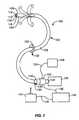
図1は、患者の解剖学的構造を侵害せずに身体内の様々な領域にアクセスするために用いられ得る操縦可能な内視鏡の一例100を示す。内視鏡100は、概して、細長い本体102を有し、本体102は、手動で、すなわち選択的に操縦可能な遠位部104、及び、自動制御される近位部106を有する。選択的に操縦可能な遠位部104は、点線で示されているように、完全な180度の屈曲まで、任意の方向に選択的に操縦され、又は曲げられ得る。光ファイバイメージングバンドル112及び1以上の照明ファイバ114が、本体102内に随意に設けられ、近位端110から遠位端108まで延在し得る。或いは、内視鏡100は、CCDカメラ又はCMOSカメラなどの小型ビデオカメラが内視鏡本体102の遠位端108に配置されたビデオ内視鏡として構成され得る。ビデオカメラからの画像は、ビデオモニタに、伝送ケーブル又はワイヤレス伝送により送信され得る。内視鏡100の本体102は、また、少なくとも1つ又は2つの器具チャネル116,118を随意に含み得る。これらのチャネルは、任意の数のツールを内視鏡内を通しアクセスさせるために用いられ得る。チャネル116,118は、他の様々な目的、例えば、吸入又は洗浄のためにも用いられ得る。 FIG. 1 shows an example 100 of a steerable endoscope that can be used to access various regions within the body without compromising the patient's anatomy. The
内視鏡100の本体102は非常に柔軟であるため、小さい直径のカーブの周りを、バックリングもキンクも生じずに曲がることができる。内視鏡100の細長い本体102は、長さが、一般的に、例えば135cm〜185cm、直径が12mm〜13mmの範囲であり得る。しかし、内視鏡100が、身体内の、例えば胃腸管内空間よりも小さい領域に用いられるのであれば、装置の直径の寸法が、より小さく変更され得る。内視鏡100の長さも、所望の用途に応じて、より長く、又はより短くされ得る。 Since the
ハンドル120が、細長い本体102の近位端110に取り付け可能である。ハンドル102は接眼レンズ124を含むことができ、レンズ124は、直接的目視のために、及び/又はビデオカメラ126への接続のために光ファイバイメージングバンドル112に接続されている。ハンドル120は、また、照明ケーブル134を介して照明源128に接続されることができ、照明ケーブル134は照明ファイバ114に接続され、又は照明ファイバ114と連続していることができる。随意に用いられる第1のルアーロックフィッティング130及び随意に用いられる第2のルアーロックフィッティング132が、それぞれ、器具チャンネル116,118に連結されることができ、これらのフィッティングは、また、ハンドル120上に、又はハンドル120の付近に配置され得る。 A
ハンドル120は、コントローラケーブル136を介して電子モーションコントローラ140に接続され得る。操縦コントロール122が、第2ケーブル138を介して電子モーションコントローラ140に接続され得る。操縦コントロール122は、医師又は外科医が、細長い本体102の選択的に操縦可能な遠位部104を所望の方向に選択的に操縦し又は曲げることを可能にするように構成され得る。操縦コントロール122は、図示されているようなジョイスティックコントローラであっても、又は、他の知られた操縦制御機構であってもよい。或いは、操縦は、手動で、例えば、ケーブル、油圧技術、若しくは空気力学技術、又は、細長い本体の遠位部を制御するための他の任意の知られた機械的装置を用いて行われ得る。電子モーションコントローラ140は、細長い本体102の自動制御される近位部106の運動を制御するために用いられることができ、マイクロコンピュータ上で実行される運動制御プログラムを用いて、又は、アプリケーションに特有のモーションコントローラを介して実行され得る。或いは、電子モーションコントローラ140は、ニューラルネットワークコントローラを用いて実行され得る。 The
軸方向移動変換器(トランスデューサ)150が、細長い本体102が前進及び後退されるときの軸方向移動を測定するために設けられ得る。軸方向移動変換器150は様々な構造でつくられることができ、それらの幾つかを以下に示す。この例において、軸方向移動変換器150は、内視鏡100の細長い本体102を取り囲むリング152として構成されており、この構成は例示のためのものに過ぎない。軸方向移動変換器150は、以下に示すように、固定された基準点(例えば手術台)、又は、患者の身体上の内視鏡100の挿入位置に取り付けられ得る。内視鏡100の本体102が軸方向移動変換器150を通ってスライドすると、軸方向移動変換器150は、固定基準点に対する内視鏡本体102の軸方向位置を示す信号を生成し、電子モーションコントローラ140に、信号を、テレメトリにより、又はケーブルを介して送信する(図示せず)。軸方向移動変換器150は、内視鏡本体102の軸方向位置を測定するために、光学的、電子的、磁気的、機械的などの方法を用い得る。さらに、移動変換器は、内視鏡の回転運動の測定及び通信も同時に行うように構成されることができ、従って、このさらなるデータが、器具の運動の制御に用いられ得る。軸方向移動変換器150に関するさらなる詳細な説明及びこの変型例が、2003年3月7日に出願された米国特許出願10/384,252号に見られ、この出願の全てを援用して本文の記載の一部とする。 An axial movement transducer (transducer) 150 may be provided to measure axial movement as the
操縦可能な内視鏡100の基本的運動を例示するために、図2Aは、内視鏡100の本体102の或るセクションの、中立又は真直位置にあるときのワイヤフレームモデルを示す。この図において、明確化のために、内視鏡本体102の内部構造の多くが省かれている。内視鏡本体102は、セクション1,2,3...10などに分割されている。各セクションの形状寸法は、a軸,b軸,c軸及びd軸に沿った4つの長さ測定値により画定される。例えば、セクション1の形状寸法は、4つの長さ測定値lla,llb,llc,lldにより画定され、セクション2の形状寸法は、4つの長さ測定値l2a,l2b,l2c,l2dにより画定され、他のセクションも同様である。各セクションの形状寸法は、a軸,b軸,c軸及びd軸に沿った4つの長さ測定値を変更するためのリニアアクチュエータを用いて変更され得る。例えば、内視鏡本体102をa軸の方向に曲げるために、測定値lla,l2a,l3a…l10aを短くし、これと同じ量だけ、測定値llb,l2b,l3b…l10bを長くすることができる。これらの測定値を変化させる量が、得られるカーブの半径を決定する。しかし、自動制御される近位部106においては、各セクションのa軸,b軸,c軸、d軸の測定値が、電子モーションコントローラ140により自動制御され得る。To illustrate the basic motion of the
図2Bにおいて、内視鏡本体102は、選択的に操縦可能な遠位部104を利用してカーブCを通るように操作されており、図2Bの時点では、自動制御される近位部106がカーブCにある。セクション1及び2は、カーブCの比較的真直な部分にあり、従って、lla=llbであり、l2a=l2bである。しかし、セクション3〜7は、S字状のカーブにあるため、l3a<l3b,l4a<l4b,l5a<l5bであるが、l6a>l6b,l7a>l7b,l8a>l8bである。内視鏡本体102が1つのユニットごとに遠位方向に前進されるとき、セクション1は、1’の符号が付された位置に移動し、セクション2は、その前にセクション1が占めていた位置に移動し、セクション3は、その前にセクション2が占めていた位置に移動し、他のセクションも同様に移動する。軸方向移動変換器150は、内視鏡本体102の、固定基準点に対する軸方向位置を示す信号を生成し、この信号を電子モーションコントローラ140に送信する。電子モーションコントローラ140の制御下で、内視鏡本体102が1つのユニットを前進させるごとに、自動制御される近位部106の各セクションが、現在そのセクションが存在している空間をその前に占めていたセクションの形状を成すように信号を送られる。従って、内視鏡本体102が、1’の符号が付された位置に前進されるとき、lla=llb,l2a=l2b,l3a=l3b,l4a<l4b,l5a<l5b,l6a<l6b,l7a>l7b,l8a>l8b,l9a>l9bであり、内視鏡本体102が、1”の符号が付された位置に前進されるとき、lla=llb,l2a=l2b,l3a=l3b,l4a=l4b,l5a<l5b,l6a<l6b,l7a<l7b,l8a>l8b,l9a>l9b,l10a>l10bである。こうして、S字状カーブは、内視鏡本体102の自動制御される近位部106の長さに沿って近位方向に伝搬する。S字状カーブは、内視鏡本体102が遠位方向に前進するため、空間に固定されているように見える。In FIG. 2B, the
同様に、内視鏡本体102が近位方向に引き戻されるとき、内視鏡本体102が1ユニットごとに近位方向に移動されるたびに、自動制御される近位部106の各セクションが、現在そのセクションが存在している空間をその前に占めていたセクションの形状を成すように信号を送られる。S字状カーブは、内視鏡本体102の自動制御近位部106の長さに沿って遠位方向に伝搬し、S字状カーブは、内視鏡本体102が近位方向に後退するため、空間に固定されているように見える。 Similarly, when the
内視鏡本体102が前進又は後退されるときはいつでも、軸方向移動変換器150が、位置の変化を検知するために用いられることができ、また、電子モーションコントローラ140が、選択されたカーブを内視鏡本体102の自動制御近位部106に沿って近位方向又は遠位方向に伝搬することができ、それにより、カーブを、空間的に固定された位置に維持し得る。同様に、内視鏡102が回転されるならば、回転運動変換器(変換器150とは独立の、又は変換器150内に一体の)が、位置の変化を検知するために用いられることができ、電子モーションコントローラが、空間的に固定された位置にカーブを維持するように内視鏡本体102の形状を調節するために、同様に用いられ得る。これは、内視鏡本体102が、曲がりくねったカーブを、不必要な力をカーブCの壁に加えずに通過することを可能にする。 Whenever the
本発明に用いられ得る他の内視鏡装置の例が、以下の特許及び同時係属出願に、より詳細に記載されている。これらの特許及び特許出願は、米国特許第6,468,203号;米国特許第6,610,007号;2002年3月1日に出願された米国特許出願10/087,100号;2002年5月2日に出願された米国特許出願10/139,289号;2002年8月27日に出願された米国特許出願10/229,577号;2002年8月27日に出願された米国特許出願10/229,814号、及び、2002年11月27日に出願された米国特許出願10/306,580号であり、これらの特許及び特許出願の各々の全てを援用して本文の記載の一部とする。 Examples of other endoscopic devices that can be used in the present invention are described in more detail in the following patents and co-pending applications. These patents and patent applications are listed in U.S. Patent No. 6,468,203; U.S. Patent No. 6,610,007; U.S. Patent Application No. 10 / 087,100 filed on March 1, 2002;
従って、上記の制御可能な内視鏡装置のいずれか1つを用いることにより、従来の外科技術を用いてはアクセス及び治療が一般的に困難な身体の様々な領域が、アクセス又は治療され得る。治療の一例において、内視鏡装置は、神経外科手術に用いられ得る。内視鏡装置が、従来は到達することが困難な脳の領域にアクセスするために「直線」(“straight-line”)条件により制約されないため、内視鏡は、頭蓋内に前進され、配置され得る。これは、装置を、脳の周囲にて、健康な脳組織に与える外傷が最小限又は無であるように操縦することにより行われる。内視鏡は、また、組織内の深部に埋まっている治療領域にアクセスするために、必要に応じて、組織内を、付近の健康な組織へのどのような損傷も最小限にし得る通路を通って前進され得る。さらに、内視鏡装置は、脳上又は脳内の繊細な領域へのアクセスを可能にし得るため、従来の手術では、頭蓋骨の一部の取り外しを通常は必要とするような場合(例えば、開頭手術又は頭蓋内血種の治療など)にも、低侵襲性外科手術が行われ得る。 Thus, by using any one of the controllable endoscopic devices described above, various regions of the body that are generally difficult to access and treat using conventional surgical techniques can be accessed or treated. . In one example of treatment, the endoscopic device can be used for neurosurgery. Because the endoscopic device is not constrained by “straight-line” conditions to access areas of the brain that are conventionally difficult to reach, the endoscope is advanced and positioned within the skull Can be done. This is done by maneuvering the device around the brain with minimal or no trauma to healthy brain tissue. The endoscope also provides a path through the tissue that, if necessary, can minimize any damage to nearby healthy tissue in order to gain access to deeply treated areas within the tissue. Can be advanced through. In addition, endoscopic devices may allow access to sensitive areas on or in the brain, so that conventional surgery usually requires removal of a portion of the skull (eg, craniotomy) Surgery or treatment of intracranial blood types, etc.) can also be performed with minimally invasive surgery.
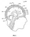
図3は、患者200の頭部202の側方断面図である。脳206が、頭蓋204の頭蓋腔210内に見られる。内視鏡装置212は、本発明の操縦可能な内視鏡の一実施形態であり、頭蓋腔内部及び脳の外側及び内側領域にアクセスするための寸法、形状及び構成を有してつくられている。内視鏡装置212の移動、配置、トラッキング及び制御は、ユーザのみにより、又は、画像システム、位置及び配置システム、並びに、手術計画の方法及び技術の幾つか若しくは全てと協働して行われる。通常はアクセスが困難であろう脳206の治療領域において、内視鏡装置212は頭蓋腔210内に、容易にアクセス可能な挿入部位222(例えば頭蓋骨内の穿孔)から挿入され得る。次いで、内視鏡装置212は、挿入部位222を通して、脳組織を回避するように操縦可能な遠位部214を制御することにより前進され得る。内視鏡212が頭蓋腔210内にさらに前進されるとき、自動制御される近位部216が、操縦可能な遠位部214により画成された形状を成して、脳組織206との接触を回避し得る。 FIG. 3 is a side cross-sectional view of the
内視鏡212は、頭蓋腔210内及び脳脊髄液内をさらに前進されることができ、こうして、装置は、髄膜の層より上、又は層内、例えばクモ膜下腔内を前進する。いずれの場合にも、内視鏡212は、脳組織206への接触又は圧力を回避し又は最小限にする通路に沿って操縦され得る。制御されている近位部16が遠位方向に前進され、遠位部214により画成された形状を成すとき、近位部216も、脳組織206への接触又は圧力を自動的に回避し又は最小限にするように同様に制御され得る。遠位部216が所望の治療領域208まで前進したならば、様々なツール220が、領域208の治療を可能にするために、器具チャネル218を通して挿入され得る。こうして、任意の数の治療又は処置、例えば、腫瘍の生検及び/又は除去、シャント配置、リード配置、装置配置、過剰な脳脊髄液又は血液の排出などが行われ得る。 The
図4は、治療を容易にするために操縦可能な内視鏡システムの位置決め方法を提供する幾つかの構成要素の相互作用を示す。先に述べたように、本発明に従う内視鏡装置の移動、配置、トラッキング及び制御は、ユーザのみにより、又は、画像システム、位置及び配置システム、並びに手術計画の方法及び技術の幾つか及び全てを用いて行われる。システムの概略図4000は、操縦可能で制御可能な本発明の内視鏡を配置及び制御するための、検知、マッピング及び制御の統合システムの一実施形態を示す。第1に、適切な装置、要素又はシステムを用いて、生理学的徴候(表示)(physiological indication)を検知及び位置特定する(4010)。生理学的徴候は、治療が行われるべき状態を示す任意の認識可能なしるしであり得る。例えば冠状動脈において、生理学的徴候を示す物は、心臓からの電気生理学的データ又は電気信号を含む。このシステムは、モニタリングされたデータを識別又は分析し、これにより、不良動作の位置を特定又は決定することができる。 FIG. 4 illustrates the interaction of several components that provide a method for positioning an endoscopic system that can be steered to facilitate treatment. As previously mentioned, the movement, placement, tracking and control of an endoscopic device according to the present invention may be performed by the user alone or by some or all of imaging systems, position and placement systems, and surgical planning methods and techniques. It is done using. System schematic 4000 illustrates one embodiment of an integrated sensing, mapping and control system for positioning and controlling a steerable and controllable endoscope of the present invention. First, a suitable device, element, or system is used to detect and localize a physiological indication (4010). The physiological sign can be any recognizable indicia that indicates the condition for which treatment is to be performed. For example, in a coronary artery, an object that exhibits physiological signs includes electrophysiological data or electrical signals from the heart. The system can identify or analyze the monitored data, thereby identifying or determining the location of the bad operation.
次に、検知及び位置特定された生理学的徴候に関する情報が、画像/マッピングシステム(4020)に送られる。画像/マッピングシステムは、任意の画像モダリティーを含むことができ、これは、位置、場所、組織タイプ、病理状態に関する情報、又は、生理学的活動を、解剖学的構造内又は基準系内の識別可能な及び/又は位置特定可能な位置と関係づけることを容易にする任意の他の情報をもたらし得る。画像/マッピングシステムの例は、画像技術(例えば、X線、蛍光透視法、コンピュータ断層撮影(CT)、3次元CATスキャン、磁気共鳴画像法(MRI)、及び、磁場を用いた位置特定システム)のいずれかを含む。心臓血管系疾患の治療に特に適した画像/マッピングシステムの例は、心電図検知システム、心臓電気生理学マッピングシステム、心内膜マッピングシステム、又は、心臓の電気生理学的データを入手、目視化、解釈し、このデータに基づいて動作する能力を有する他のシステム及び方法を含む。このようなシステムの例が、「多電極カテーテルを用いた心内膜活性化マッピングのための方法」と題する米国特許第5,848,972号に記載されており、この特許の全てを援用して本文の記載の一部とする。さらなる例は、米国特許第5,487,385号;米国特許第5,848,972号;及び、米国特許第5,645,064号に記載されており、これらの特許の各々の全てを援用して本文の記載の一部とする。統合されたマッピング、検知及び/又はアブレーションプローブ及び装置も、本発明の操縦可能な内視鏡を用いて配送され得る。このような統合システムの一例が、スワンソン(Swanson)らの米国特許出願公開公報2003/2336455に記載されており、この公報の全てを援用して本文の記載の一部とする。さらなる他のシステムは、不整脈の原因を治療するために、心臓の局所的等時作動マップのマッピング、表示又は位置情報を、内視鏡の相対位置、及び、内視鏡(又は、内視鏡に搭載された部品、要素若しくはシステム)を配置するための方向情報又は移動命令と共に提供し得る。 Next, information about the detected and localized physiological signs is sent to the image / mapping system (4020). The image / mapping system can include any image modality that can identify location, location, tissue type, pathological state information, or physiological activity within an anatomy or reference system And / or any other information that facilitates associating with a locable location. Examples of image / mapping systems are imaging technologies (eg, X-ray, fluoroscopy, computed tomography (CT), three-dimensional CAT scan, magnetic resonance imaging (MRI), and localization system using magnetic fields). One of these. Examples of imaging / mapping systems that are particularly suitable for the treatment of cardiovascular disease include obtaining, visualizing, and interpreting electrocardiographic data, electrocardiographic sensing systems, cardiac electrophysiological mapping systems, endocardial mapping systems, or cardiac electrophysiological data. And other systems and methods having the ability to operate based on this data. An example of such a system is described in US Pat. No. 5,848,972 entitled “Method for Endocardial Activation Mapping Using a Multielectrode Catheter”, which is incorporated by reference in its entirety. As part of the description. Further examples are described in US Pat. No. 5,487,385; US Pat. No. 5,848,972; and US Pat. No. 5,645,064, each of which is incorporated by reference. As a part of the description of the text. Integrated mapping, sensing and / or ablation probes and devices can also be delivered using the steerable endoscope of the present invention. An example of such an integrated system is described in Swanson et al., US Patent Application Publication 2003/2335365, which is incorporated herein by reference in its entirety. Still other systems may be used to map, display or position information of the local isochronal map of the heart, the relative position of the endoscope, and the endoscope (or endoscope) to treat the cause of the arrhythmia. The information may be provided along with direction information or movement instructions for placing a component, element or system mounted on the device.
次に、前のステップにて提供され、受け入れられ、及び/又は分析された情報、又は、ユーザ若しくはユーザが用いている他のシステムにより提供されたさらなる他の情報が、内視鏡コントローラに入力され、又は内視鏡コントローラにより用いられる(4030)。このステップは、内視鏡コントローラが、表示、位置、画像、マッピング及び他のデータに応答することができ、また、このデータを用いて、内視鏡の形状、位置、向きを変更できることを示す。又は、提供された情報に内視鏡コントローラが応答していることを示す、他の関連する情報を示す。内視鏡は、モニタリングされている生理学的徴候の治療を容易にするための部品、要素又はシステム提供することを容易にするように構成されている。コントローラは、提供されたデータを利用して、操縦可能で制御可能な内視鏡を、不良動作を示す場所又は部位に関する位置に配置する。不良動作を示す場所又は部位への内視鏡の近接性は、例えば、行われている治療、治療を容易にするために用いられている要素、部品又はシステムに依存する。 Next, the information provided, accepted and / or analyzed in the previous step, or further information provided by the user or other system used by the user, is input to the endoscope controller. Or used by an endoscope controller (4030). This step indicates that the endoscope controller can respond to display, position, image, mapping and other data and can use this data to change the shape, position and orientation of the endoscope . Or other relevant information indicating that the endoscope controller is responding to the provided information. The endoscope is configured to facilitate providing a component, element or system for facilitating treatment of the physiological sign being monitored. The controller uses the provided data to place the steerable and controllable endoscope in a position relative to the location or site that exhibits the malfunctioning. The proximity of an endoscope to a location or site that exhibits poor operation depends, for example, on the treatment being performed, the elements, components, or systems being used to facilitate the treatment.
最後に、内視鏡の位置が、画像又はマッピングシステムに、フィードバックの形態で還元され、これにより、治療を容易にするために内視鏡を所望の位置にガイドすることが、より良好に補助される(4040)。 Finally, the position of the endoscope is reduced to the image or mapping system in the form of feedback, which better assists in guiding the endoscope to the desired position to facilitate treatment. (4040).
別の実施形態において、システム4000は、治療を容易にする医学的に重要なデータを提供する、全体マッピングシステムを含み得る。この全体マッピング又は画像システムは、モニタリングされている活動の領域をマッピング又は画像化することを含み得る。モニタリングされる活動領域は、治療に重要な身体部位を含むだけでなく、身体の他の部分、すなわち、治療による影響を受けないが、その代わりに、操縦可能で制御可能な内視鏡の、治療が促進されるであろう領域への通路となり得る部分の画像情報も含む。次いで、これらの表示は、操縦可能で制御可能な内視鏡を、治療を容易にするために所望の位置にガイドすることを促進するために用いられ得る。また、他の医用画像システム及びトラッキングシステムも、トラッキング、ガイド、及び位置フィードバック情報を、操縦可能な内視鏡の制御に提供するために用いられ得る。このようなシステムの例が、米国特許第5,377,678号にてデュムラン(Dumoulin)らにより記載されており、この特許を援用して本文の記載の一部とする。 In another embodiment, the
上記のステップは、操縦可能な内視鏡により用いられるガイドシステム及びコントロールの機能を高めるために、生理学的徴候及び位置情報がどのように利用され、内視鏡の配置を確実にし、それにより治療を容易にするかを示す実施形態の一例に過ぎない。これらのステップが、論議を明確で簡単にするために用いられたことを理解されたい。本発明の実施形態の方法はこれらのステップに限定されない。例えば、単一のシステムが、内視鏡位置のフィードバックをリアルタイムで受信する、表示、画像化が統合された内視鏡コントローラとして用いられ得る。別の例において、生理学的表示と画像/マッピング機能とが、単一のユニットに組み合わされ得る。従って、上記のステップを、一回のみ、又は連続して行うように記載したが、これらのステップが、異なる順序で、又は複数回行われ得ることが理解されよう。生理学的徴候を検知及び位置特定する他のシステムも用いられることができ、これらは、行われる治療に有用な適切なシステムに応じて用いられる。さらに、別の画像及びマッピングシステムも用いることができ、これらも、本発明の操縦可能で制御可能な内視鏡の使用により容易にされる治療に応じて選択され得る。このシステムは、また、内視鏡の移動を、ユーザからの入力、術前計画データ、又は、望ましい通路又は回避すべき通路の他の表示に基づいて自動的に制御し得る。或いは、又は、これに加えて、ユーザは、さらなるガイド又は制御情報を、システムに、内視鏡のガイド又は望ましい配置を促進するために入力し得る。 The above steps show how the physiological signs and position information are used to enhance the function of the guide system and controls used by the steerable endoscope to ensure the placement of the endoscope and thereby the treatment. It is just an example of an embodiment showing how to facilitate the process. It should be understood that these steps were used to clarify and simplify the discussion. The method of the embodiment of the present invention is not limited to these steps. For example, a single system can be used as an endoscope controller with integrated display and imaging that receives endoscope position feedback in real time. In another example, the physiological display and image / mapping function can be combined into a single unit. Thus, although the above steps have been described as being performed only once or sequentially, it will be understood that these steps may be performed in a different order or multiple times. Other systems for detecting and locating physiological signs can also be used, depending on the appropriate system useful for the treatment being performed. In addition, other image and mapping systems can be used, which can also be selected depending on the treatment facilitated by the use of the steerable and controllable endoscope of the present invention. The system may also automatically control the movement of the endoscope based on input from the user, preoperative planning data, or other indications of desired or avoidable paths. Alternatively or in addition, the user may input additional guide or control information into the system to facilitate the guide or desired placement of the endoscope.
内視鏡装置が用いられ得る別の治療分野は、冠動脈手術(例えば僧帽弁の治療)、上室性頻拍症の治療(例えば、心房細動の治療のための組織アブレーションを含む)を行い又は容易にすること、心室頻拍のみの治療又は、上室性頻拍症の治療と組み合わせての治療、装置リードの設置、再配置又は装置の除去のための処置などを含む。心房細動は、典型的に、心臓の心房にて同時に伝搬する多数のリエントリー性ウェーブレット(電気波)の存在により持続する。外科的及びカテーテルベースの技術は、心房を再同期化する1つの方法として、一般に、肺静脈付近又はその周囲の、分割され又は連続した病変部にアブレーションを施す。 Other therapeutic areas where endoscopic devices may be used include coronary artery surgery (eg, mitral valve treatment), supraventricular tachycardia treatment (eg, including tissue ablation for the treatment of atrial fibrillation). Treatment or treatment, treatment of ventricular tachycardia alone or in combination with treatment of supraventricular tachycardia, treatment of device lead placement, repositioning or device removal, and the like. Atrial fibrillation is typically sustained by the presence of multiple reentrant wavelets (electrical waves) that propagate simultaneously in the heart's atrium. Surgical and catheter-based techniques generally ablate a segmented or continuous lesion near or around the pulmonary vein as one method of resynchronizing the atria.
さらに、エネルギーベースの(energy based)形態(modality)及び非エネルギーベースの(non-energybased)形態を用いた様々なアブレーション技術が、軟組織をアブレーション(焼灼)するために用いられ得る。本発明の実施形態は、1つのエネルギー・モダリティ又はエネルギー・モダリティの組み合わせを用いるアブレーション治療、アブレーション要素及び装置の使用を容易にするために用いられ得る。エネルギー・モダリティは、例えば、極低温エネルギー、油圧エネルギー、レーザエネルギー、磁気エネルギー、機械的エネルギー、マイクロ波エネルギー、放射線エネルギー、高周波エネルギー、熱エネルギー、及び超音波エネルギーである。マイクロ波アブレーションシステムは、AFxマイクロ波外科アブレーションシステムに基づいたシステム、例えば、AFxFlex4などを含み得る。AFxは、現在、ガイダント・コーポレーション(Guidant Corp.)により所有されている。極低温アブレーションシステムは、例えば、クライオキャス・テクノロジ社(Cryocath Technology)から販売されているシステム、例えば、「サージフロスト」(SurgiFrost)、「フロストバイト」(Frostbyte)、又は「アーティックサークラ」(Artic Circler)システムなどを含み得る。超音波ベースの外科用プローブは、例えば、エピコ・メディカル社(EpiCor Medical)などにより製造されている超音波アブレーションシステムに基づき得る。多数の市販のアブレーションシステムが、本発明の操縦可能な内視鏡システムの実施形態により配送又は利用され得る様々な種類のアブレーションシステム、技術及び形態の例であり得る。 In addition, various ablation techniques using energy based and non-energy based configurations can be used to ablate soft tissue. Embodiments of the invention can be used to facilitate the use of ablation treatments, ablation elements and devices using one energy modality or a combination of energy modalities. The energy modalities are, for example, cryogenic energy, hydraulic energy, laser energy, magnetic energy, mechanical energy, microwave energy, radiation energy, high frequency energy, thermal energy, and ultrasonic energy. Microwave ablation systems may include systems based on AFx microwave surgical ablation systems, such as AFxFlex4. AFx is currently owned by Guidant Corp. Cryogenic ablation systems are, for example, systems sold by Cryocath Technology, such as “Surgi Frost”, “Frostbyte”, or “Artic Circle” ( Artic Circler) system etc. Ultrasound-based surgical probes can be based on, for example, an ultrasound ablation system manufactured by EpiCor Medical. A number of commercially available ablation systems can be examples of the various types of ablation systems, techniques and configurations that can be delivered or utilized by the steerable endoscope system embodiments of the present invention.
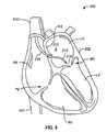
図5に示されているように、心臓302の前方断面図が、左心房LAと左心室LVとの間に位置する僧帽弁MVの治療のための冠動脈手術300に見られる。この治療例において、内視鏡装置212が、上大静脈SVCを通して心臓302内に挿入され、右心房RA内を前進している様子が示されている。また、三尖弁TVより下の右心室RV、及び下大静脈IVCも示されている。従って、内視鏡212は、血管内を配送されるような寸法を有し得る。内視鏡装置212が右心房RA内に配置されたならば、遠位部214が、左心房LAと右心房RAとを隔てている心房中隔ASに向けて操縦され得る。遠位部が心房中隔ASに達したならば、装置212内を通して配送可能な切断ツールを用いて心房中隔ASに穴をあけることができ、これにより、内視鏡装置212が左心房LAに入ることが可能になる。次いで、遠位部214は、操縦されて僧帽弁MV付近に配置され得る。この間、近位部216は、装置212により心臓302の組織に加えられる可能性がある全ての圧力を最小化するように自動制御され得る。内視鏡装置が、治療されるべき組織(この例においては僧帽弁MV)付近に達したならば、治療を行うために様々なツール又は装置がチャネル218を通して配送され得る。処置が完了したならば、内視鏡212は、挿入時と同様に、組織に対する接触圧力を最小限ながら、近位方向に簡単に引き戻され得る。 As shown in FIG. 5, an anterior cross-sectional view of
内視鏡装置が用いられ得るさらに別の治療領域において、様々な胸腔鏡手術が低侵襲性処置により行われ得る。図6は、経皮的に行われ得る胸腔鏡手術400の例を示す。図示されているように、内視鏡212は、患者402の身体内に、導入器又はポート412を介して前進され得る。ポート412は、手術中に内視鏡212のための固定された参照点を確立するための基準点としても構成され得る。ポート又は基準点412は、電気線418を介してコンピュータ又はプロセッサ416と電気通信することができ、これは、装置21の患者402内での位置を決定及び/又は維持するために用いられ得る。内視鏡212は、患者402の身体内に、切開414(例えば、肋骨404間の肋間隙に形成される)を通して前進され得る。次いで、内視鏡212は胸腔内に前進され、操作されて、身体内の領域、例えば心臓408の後方領域に達し得る。この領域は、直線的アクセスがないために従来の腹腔鏡術では通常はアクセスできない領域である。 In yet another therapeutic area where endoscopic devices can be used, various thoracoscopic procedures can be performed with minimally invasive procedures. FIG. 6 shows an example of
この例において、内視鏡212が、ポート又は基準点412を通して挿入され、胸骨406の後ろを通って心臓の408の後方に前進されている様子が示されている。図を明確にするために肺は示されていない。しかし、内視鏡212は、肺組織、又は、直線通路を妨げ得る他の器官若しくは構造物との接触を回避し、又は接触を最小限にするように、先に記載したようなやり方で肺を避けて操縦及び前進され得る。 In this example, an
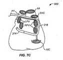
内視鏡212は、従来の腹腔鏡術では通常アクセスできない身体内の領域に、周囲組織を損傷することなく到達することができる。図7A〜図7Dは、内視鏡装置が、上室性頻拍症の治療を容易にするために心臓の後方領域周辺を前進されている例を示す。上室性頻拍症の一例は心房細動である。別の処置500が図7A〜図7Dに示されており、心房細動の治療のために内視鏡装置がどのように用いられ得るかを示す。これらの図は、心臓の後方図であり、大動脈AA及び肺動脈幹PTが、解剖学的ランドマーク(目印)として示されている。心房細動は、典型的に、心臓の心房にて同時に伝搬する多数のリエントリー性ウェーブレット(電気波)の存在により持続する。外科的及びカテーテルベースの技術は、心房を再同期化する1つの方法として、一般に、肺静脈付近又はその周囲の、分割され又は連続した病変部にアブレーションを施す。 The
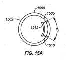
内視鏡装置212は、装置212を、先に記載したように胸腔内に前進させることにより、又は、様々な他の通路を通して前進させることにより用いられ、心臓の後方領域に向って操縦され得る。図7A〜図7Dに示した例において、操縦可能な遠位部214は、図7Aに示されているように、内視鏡212が左肺静脈LPVより上に接近するように前進され得る。図7Bに示されているように、遠位部214は、内視鏡212が遠位方向に前進されているとき、右肺静脈RPVの周辺に操縦され得る。そして、自動制御可能な近位部216は、遠位部214が肺血管周辺を移動しているときに画成された形状を成し得る。図7Cに示されているように、遠位部214は左肺血管LPVの周囲に操縦され、近位部は、装置が右肺静脈RPV周囲を移動することで形成された湾曲通路の形状を成している。最後に、図7Dにおいて、装置212は、遠位部214及び近位部216が装置の配置を維持したまま心臓組織と密接に接触するように完全に前進され、肺血管の周囲全体を取り囲み得る。次いで、装置212と接触している組織が、遠位部214及び/又は近位部216の長さに沿って配置された1又は複数の電極によりアブレーションされ得る。これに関しては、以下にさらに詳細に説明する。或いは、アブレーション装置、例えばカテーテル、又は他のエネルギー源が、内視鏡内又は内視鏡上の1以上の作業チャネルを通して配送されて、所望のように、適切な位置に配置され得る。次いで、このアブレーション装置は、本文中に記載されている、又は当業者に知られている様々な形態のアブレーションエネルギー(例えば、高周波、マイクロ波、極低温冷却など)を配送するために用いられ得る。装置は、所望の位置に、様々な方法、例えば、真空、磁気的、一時的接着、縫合により、又は、装置と組織とを取り付け又は接近させる他の任意の方法により固定されて保持され得る。
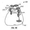
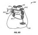
図8A〜図8Dは、処置の一例600を示す。この処置において、操縦可能な内視鏡装置が心臓の後方領域周辺に前進され、次いで、上室性頻拍症の治療を容易にするための装置を配備するために引き戻されている。操縦可能な内視鏡装置800は、身体内の領域に、先に記載したように、また、腹腔鏡術よりも改善された方法で到達できる。図8A〜図8Dは、心臓の後方図を、解剖学的ランドマークとしての大動脈AA及び肺動脈PTと共に示す。図8Aは、操縦可能で制御可能な遠位端805及び制御可能な近位端810を有する内視鏡装置800を示す。図8Aにおいて、処置600の最初に、内視鏡装置800は、アブレーション装置815の配備を開始するための位置に移動されている。この例示的な処置600において、操縦可能な内視鏡装置800は、肺静脈周囲の望ましい配備通路、すなわち治療通路を通ることにより初期配備点に移動されたことが理解されよう。処置600を論じる目的で肺静脈に関して例示しているが、操縦可能な内視鏡は、肺静脈に用いることに限定されず、器官、組織及び身体部分周辺の所望の治療通路を、所望のように通過するように用いられ得る。図8Aは、また、アブレーション装置815の遠位端が、心臓に、本出願に記載され、又は当業者に知られている取付け方法のいずれかを用いて取り付けられている様子を例示している。 8A-8D illustrate an
次に、図8B及び図8Cにおいて、操縦可能な内視鏡800は、アブレーション装置815を残して通路に沿って近位方向に引き戻されている。図8Dにおいて、最終的に、アブレーション装置815は、操縦可能な内視鏡800により形成された望ましい配備通路にて、肺静脈周囲に完全に配備されている。この時点で、処置600にて可能な多数の選択肢がある。内視鏡800は、アブレーション装置815を用いた治療中に引き出され得る。内視鏡800は、アブレーション装置815が複数のアブレーション要素を含む実施形態において、アブレーション装置815に沿って分布された各アブレーション要素の位置及び向きを目視検査するために用いられ得る。この例示された実施形態において、アブレーション装置815は、例示が容易であるように、単一のアブレーション要素として示されている。内視鏡は、アブレーション装置815が処置を容易にするための望ましい位置に適切に配備されたことを確認するためにも用いられ得る。さらに、内視鏡は、アブレーション装置815の位置を肺静脈に対して維持するために用いられる任意の固定具若しくは接着剤又は固定手段を目視検査するために用いられ得る。 Next, in FIGS. 8B and 8C, the
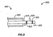
図9は、治療装置の一実施形態を示し、この治療装置は、周囲組織との接触を容易にするための複数の固定具を有する。内視鏡装置900は、アブレーション装置915を配備するために、又はアブレーション装置915の配備を容易にするために配置される、制御可能で操縦可能な端部905を有する。アブレーション装置915は、複数のアブレーション要素920を有する。アブレーション装置915は、また、アブレーション治療を容易にするためにアブレーション装置915と周囲の組織、器官及び身体部分との接触を増大するための複数の固定具925を有する。アブレーション要素920に対する固定具925の位置が、アブレーション要素920と周囲組織との最大接触をもたらし、且つ、周囲組織に対するアブレーション要素920の配置を保証するためのものであることを留意されたい。固定具925は、他の位置にあってもよく、また、他の形状であってもよく、また、本出願の他のいずれかの箇所に記載されるタイプの、及び/又は、当業者に知られている固定具であってもよい。 FIG. 9 illustrates one embodiment of a treatment device that has a plurality of fasteners for facilitating contact with surrounding tissue.
操縦可能な内視鏡900の別の実施形態において、固定具925は、操縦可能な先端905が近位方向に引き戻されるとき、固定具925が周囲組織と係合してアブレーション装置915の位置を固定するように構成され得る。アブレーション装置915が配置されたならば、アブレーション治療が所望のように続行される。アブレーション治療が完了したならば、操縦可能な内視鏡900は、アブレーション装置915の遠位端から近位方向に前進される。操縦可能な内視鏡先端905が遠位方向に、固定具925を超えて前進すると、固定具925は、アブレーション装置915と共に、操縦可能な内視鏡900内に引き込まれる。広く様々な固定具のいずれもが、周囲組織と係合するために用いられ得ることを理解されたい。例えば、固定具925は、超弾性の又は形状記憶合金材料から形成され得る。形状記憶合金材料の特性は、固定具を周囲組織と係合させるために体温の熱エネルギーが用いられるように選択され得る。或いは、形状記憶合金固定具は、周囲組織と係合するために形状記憶効果を発するように選択的に作動され得る。組織との係合は、組織の表面を切断する固定具だけでなく、組織の表面を損傷しない固定具も含む。幾つかの固定具が、操縦可能な内視鏡の移動により周囲組織との係合を外され得るが、周囲組織から固定具を外すことを容易にするためのツール又は要素が、内視鏡900の遠位端上又は遠位端に存在し得ることを理解されたい。 In another embodiment of the
図10A及び図10Bは、内視鏡装置が、上室性頻拍症の治療(図10A)、及び、上室性頻拍症と心室頻拍症の組み合わせの治療(図10B)を容易にするために心臓の後方領域周辺を前進されているさらなる例を示す。特定の例において、図10Aは、心房細動の治療の別の変型600を示す。この例において、装置は、肺静脈周囲にて、左肺静脈LPVを囲む第1の包囲602、及び、右肺静脈RPVを囲む第2の包囲604にて連続して輪を形成するように操縦及び配置され得る。内視鏡212の包囲部602,604は、肺静脈LPV,RPVの周囲のみの心臓組織をアブレーションするように作動され得る。或いは、包囲部602,604は、心臓組織を、遠位部214及び近位部216の両方の全長に沿ってアブレーションするように作動され得る。さらには、先に述べたように、様々なアブレーション装置が所望の領域に配送され得る。 10A and 10B show that the endoscopic device facilitates treatment of supraventricular tachycardia (FIG. 10A) and treatment of a combination of supraventricular tachycardia and ventricular tachycardia (FIG. 10B). In order to do this, a further example is shown which is being advanced around the posterior region of the heart. In a particular example, FIG. 10A shows another
別の特定の例において、図10Bは、心房細動の治療の別の変型650を示す。この例において、装置は、肺静脈周囲にて、左肺静脈LPVを囲む第1の包囲602、及び、右肺静脈RPVを囲んで心室の一部を横切る(654)第2の包囲652にて連続して輪を形成するように操縦及び配置され得る。内視鏡212の包囲部602,652,654は、肺静脈LPV,RPV周囲の心臓組織と、部分654付近の心室部とをアブレーションするように作動され得る。或いは、包囲部602,652,654は、心臓組織を、遠位部214及び近位部216の両方の全長に沿ってアブレーションするように作動され得る。さらに、先に述べたように、様々なアブレーション装置が所望の領域に配送され得る。 In another specific example, FIG. 10B shows another
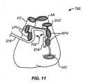
図11は、内視鏡装置を用いた心房細動の治療の別の例を示す。特定の実施形態において、図11は、さらに別の変型700を示す。この例において、内視鏡216は、取り囲まれた領域702が形成されるように、肺静脈LPV,RPVの後方付近の組織の一部と接触するように前進及び操縦され得る。図示されているように、本発明の操縦可能な内視鏡の実施形態は、心臓の治療を容易にするために、冠血管系又は他の心臓の目印の一部の周囲に配置され得る。この特定の例において、内視鏡216は、本文中に記載した技術を用いて、肺静脈内部及びその付近の位置に移動され、下大静脈に向って前進されている。本発明の操縦可能な内視鏡は、空間及び位置の構成及び制御が非常に容易であるため、治療用装置、要素及びシステムを、治療を促進するために心臓の周囲及び身体内の他の場所に配置することを可能にする。 FIG. 11 shows another example of treatment of atrial fibrillation using an endoscope apparatus. In certain embodiments, FIG. 11 shows yet another
図12A及び図12Dは、上室性頻拍症及び/又は上室性頻拍症と心室頻拍症との組合せの治療を容易にするために心臓の後方領域周辺を前進する、本発明の操縦可能な内視鏡装置のさらに別の実施形態を示す。図10A及び図10Bに関して以上に記載したように、左肺静脈(LPV)及び右肺静脈(RPV)は、例示及び論述のための目印として用いられ、限定のためのものではない。図12Aは、内視鏡装置1200がLPV及びRPVの両方の周囲に配置され、LPVの一方を取り囲み、次いで前方に進んで心臓の心室部を横切る(1205)様子を示す。図12Bは、内視鏡装置1200がLPV及びRPVの両方の周囲に配置され、次いでLPVの一方を取り囲み、次いで横方向に進んで心臓の心室部を横断する(1210)様子を示す。図12Cは、両方のRPVの周囲に配置された内視鏡装置1200がLPVを部分的に取り囲み、次いで前方に進んで心臓の心室部を横切る(1205)様子を示す。図12Dは、アブレーション治療を容易にするために2つの内視鏡装置1250及び内視鏡装置1260が用いられる本発明の一実施形態を示す。第1の操縦可能な内視鏡装置1250は、心臓を横断し、LPV及びRPVを部分的に取り囲むように配置される。第2の操縦可能な内視鏡装置1260は、LPVに隣接して配置され、RPVを取り囲み、次いで、前方に進んで心臓心室表面を横切る(1205)。第2の操縦可能な内視鏡1260により容易にされる第2のアブレーション治療と同時に、若しくはその後、又はこれに連続して、第1の操縦可能な内視鏡1250が第1のアブレーション治療を容易にするために用いられ得ることが理解されよう。これらの例示的な実施形態が示すように、本発明の操縦可能な内視鏡は、広く様々な状況において、アブレーション治療を容易にすすめるように配備され得る。 12A and 12D illustrate an embodiment of the invention that advances around the posterior region of the heart to facilitate treatment of supraventricular tachycardia and / or a combination of supraventricular tachycardia and ventricular tachycardia. 6 illustrates yet another embodiment of a steerable endoscopic device. As described above with respect to FIGS. 10A and 10B, the left pulmonary vein (LPV) and right pulmonary vein (RPV) are used as landmarks for illustration and discussion and are not intended to be limiting. FIG. 12A shows the
図13は、心臓の治療を容易にするために用いられる本発明の操縦可能な二重内視鏡1300の実施形態を示す。操縦可能な二重内視鏡1300は、第1の操縦可能な内視鏡1350と、第1の操縦可能な内視鏡1350内に配置された第2の操縦可能な内視鏡1310とを含む。一実施形態において、内視鏡1305,1310は、両方共、初期状態(I)に関節状に曲げられる。その後、第2内視鏡1310は、通路(a)〜(i)に沿って、LPV,RPVを取り囲むために進み、次いで、心臓の心室部を横切って進む。第2内視鏡1310は、ユーザの制御下で通路に沿って進み得る。或いは、第2内視鏡1310は、術前計画画像、リアルタイム画像、検知又はトラッキングシステムからの入力を受信するマッピングシステムのいずれか、又はこれらの組合せに基づいて自動的に配備することにより、通路に沿って進み得る。別の方法において、第2内視鏡1310は、自動制御及びユーザ入力の組合せを用いて進む。 FIG. 13 shows an embodiment of a steerable
第1及び第2の操縦可能な内視鏡を、以上に、心臓治療のための使用に関して記載したが、第2の操縦可能な内視鏡の寸法を第1内視鏡の寸法よりもかなり小さく維持することにより、神経血管系の一部及び他の領域にアクセスするために用い得ることが理解されよう。例えば、第1の内視鏡は、第1の位置に配置され、且つ、この第1位置に、第2の操縦可能な内視鏡のための安定したプラットフォーム(基盤)及び/又は基準点として機能するように取り付けられ得る。この安定した基盤から、第2内視鏡が、治療を容易にするために配備され得る。 Although the first and second steerable endoscopes have been described above for use for cardiac therapy, the dimensions of the second steerable endoscope are much larger than the dimensions of the first endoscope. It will be appreciated that by keeping small, it can be used to access parts of the neurovascular system and other areas. For example, a first endoscope is placed in a first position and in this first position as a stable platform and / or reference point for a second steerable endoscope Can be mounted to function. From this stable base, a second endoscope can be deployed to facilitate treatment.
図14A〜図14Cは、それぞれ、組織アブレーション治療のために内視鏡上に配置された電極の様々な構成の側方図及び端面図を示す。内視鏡900は、治療を容易にするための多数の要素、装置又はシステムと共に構成され得る。特定の一実施形態において、本発明の操縦可能な内視鏡は、内視鏡外面に沿って配置された複数の電極を有し得る。図示されているこれらの電極は、本文中に記載したように、内視鏡の長さ、又は選択された長さ領域に沿った組織アブレーションを容易にするためのものである。これらの図は、操縦可能な遠位部904及び自動制御可能な近位部902の一部を、内視鏡900上の電極配置の一例として示す。図に見られるように、1又は任意の数の電極906は、内視鏡900の長さに沿って間隔を有して、周方向に、例えばリング状に配置され得る。内視鏡906は、この例においては、均等な間隔で配置されているように示されているが、電極は、内視鏡900の外面上に、どのようなランダムな、任意の、又は特定の配置でも構成され得る。電極906の各々は、対応するワイヤ908を介して電源及び/又はコントローラに電気接続され得る。こうして、全ての電極906が、同時に作動するように、又は、組織と接触し得る選択された電極906のみが作動するように構成され得る。さらに別の変型例において、これもまた先に記載したように、様々なアブレーション装置が所望の領域に配送され得る。 14A-14C show side and end views, respectively, of various configurations of electrodes placed on an endoscope for tissue ablation treatment. The
図14Bは、別の変型例を内視鏡910にて示す。この例において、電極916は、近位部912及び/又は遠位部914上にて長手方向に延在するように構成され得る。電極は、内視鏡長さに沿った連続したストリップとして構成され得る。或いは、電極916は、図示されているように、内視鏡910上の長手方向に分割されて延在するように構成され得る。分割型の電極916を有することは、選択された電極が組織アブレーション中に作動されることを可能にし得る。図14Bは、例示のために、単一列に配置された電極916を示しているが、図14Cの例に示されているように、複数列の電極が装置の外面上に配置されてもよい。図14Cは、複数列の電極918が内視鏡表面の円周上に均等に間隔を有して配置されている様子を示す。 FIG. 14B shows another modification example with an
以上に記載したこれらの例は、例示のためのものであり、限定的のためのものではない。どのような他の形状も、内視鏡装置の、周囲組織との過度の接触が回避されるように操縦及び配置される能力により達成され得る。さらに、胸腔内の任意の数の様々な領域に、周囲組織及び器官への損傷を最小限にし、又は全く生じずにアクセスすることが、上記の制御可能な内視鏡装置を用いて達成され得る。内視鏡を用いた他の治療例は、リード配置、植え込み可能な装置の配置、肺の治療(例えば肺気腫治療)などを含み得るが、これらの例に限定されない。 These examples described above are intended to be illustrative and not limiting. Any other shape may be achieved by the ability of the endoscopic device to be steered and positioned so as to avoid excessive contact with surrounding tissue. Furthermore, accessing any number of various regions within the thoracic cavity with minimal or no damage to surrounding tissues and organs is achieved using the controllable endoscopic device described above. obtain. Other treatment examples using an endoscope may include, but are not limited to, lead placement, placement of implantable devices, lung treatment (eg, emphysema treatment), and the like.
容易にされるべき治療に応じて、治療ツール、要素、又は装置と、治療を受ける身体の組織、器官又は部分との接触の程度を増大し、又は位置を保証することが有利であろう。接触を増大し、又は、治療装置の位置を固定するための手段の例は、生体適合性の接着剤、粘着剤及びゲルを単独で用いること、又は、ステープル、吸引、ワイヤ、刺付きフック及び刺無しフック、若しくは、特定の解剖学的構造を取り囲む形状のフックと組み合わせることを含む。特定の解剖学的構造を取り囲む形状のフックの一例は、冠血管系周囲を少なくとも部分的に取り囲むJ字状フックを含む。例えば、J字状フックは、肺静脈を少なくとも部分的に取り囲むように形成され、配置され得る。別の例において、ワイヤ、ステープル、又は他の固定部品が、形状記憶合金材料、例えばニチノール、又は、他の適切な生体適合性の形状記憶合金材料から形成され得る。形状記憶合金固定具は、治療を容易にする以前に治療部位に進んでいくとき、最初の、すなわち収容された状態で保持され得る。治療装置が配置されたならば、形状記憶合金固定具は作動され、形状記憶効果を用いて治療装置を所望の位置に固定し得る。 Depending on the treatment to be facilitated, it may be advantageous to increase the degree of contact or ensure the position of the treatment tool, element or device and the body tissue, organ or part undergoing treatment. Examples of means for increasing contact or fixing the position of the treatment device include the use of biocompatible adhesives, adhesives and gels alone, or staples, suction, wires, barbed hooks and In combination with a stabless hook, or a hook shaped to surround a particular anatomical structure. An example of a shaped hook that surrounds a particular anatomical structure includes a J-shaped hook that at least partially surrounds the coronary vasculature. For example, a J-shaped hook can be formed and arranged to at least partially surround the pulmonary vein. In another example, a wire, staple, or other securing component may be formed from a shape memory alloy material, such as nitinol, or other suitable biocompatible shape memory alloy material. The shape memory alloy fixture can be held in its original, or stowed state, as it proceeds to the treatment site prior to facilitating treatment. Once the treatment device is in place, the shape memory alloy fixture can be activated to lock the treatment device in the desired position using the shape memory effect.
別の実施形態において、治療を容易にするために、磁気部を有する操縦可能な内視鏡が、身体の組織、器官又は領域周辺に配備され得る。その後、操縦可能な内視鏡は、アブレーションシステムを配置するためのガイドとして用いられ得る。永久磁石又は電磁石が、アブレーションシステムを操縦可能な内視鏡付近の所望の位置に磁気的に連結するために用いられ得る。処置が完了したならば、磁界は遮断され、アブレーションシステム及び操縦可能な内視鏡が引き戻される。操縦可能な内視鏡の付近に配備され得る。 In another embodiment, a steerable endoscope with a magnetic part may be deployed around a body tissue, organ or region to facilitate treatment. The steerable endoscope can then be used as a guide for positioning the ablation system. Permanent magnets or electromagnets can be used to magnetically couple the ablation system to a desired location near the steerable endoscope. When the procedure is complete, the magnetic field is interrupted and the ablation system and steerable endoscope are pulled back. It can be deployed near a steerable endoscope.
別の実施形態においては、操縦可能な内視鏡自体が、身体の器官、組織又は部分周囲に治療を行うために巻き付けられ、次いで、治療を促進するために内視鏡自体に固定され得る。或いは、内視鏡の遠位端を、溶解性の縫合糸又は溶解性の生体適合性固定具で固定してもよい。これらの縫合糸及び固定具は、アブレーション治療の完了後まで適切な位置に留まり、次いで、組織に吸収され、又は溶解する。 In another embodiment, the steerable endoscope itself can be wrapped around the body organ, tissue or part to provide treatment and then secured to the endoscope itself to facilitate treatment. Alternatively, the distal end of the endoscope may be secured with a soluble suture or a soluble biocompatible fixture. These sutures and fasteners remain in place until after the ablation treatment is complete, and then are absorbed or dissolved by the tissue.
さらに、アブレーション装置若しくは操縦可能な内視鏡、又はこれらの両方の、長さ又は長さの一部に沿って、ニードルのアレイが配置され得る。一実施形態において、RF(高周波)アブレーションをベースとしたデリバリシステムと、治療を受ける組織との接触を増大するために、導電性ニードルのアレイが配置される。ニードルアレイだけでなく、他の適切な要素も、他のアブレーション方法の効率を高めるために用いられ得る。従って、ニードルアレイがRFアブレーションエネルギーの配送の効率を増大するように記載されていても、他の要素及び構成も、他のアブレーション治療方法の効率を増大するために用いられ得ることが理解されるべきである。或いは、非エネルギーベースのアブレーション、例えば、組織の裂傷を用いるアブレーション技術のためには、要素は、組織を切断するための、又は、治療効果を得るために組織を他の何らかの方法で変化させるための、任意の適切な装置であり得る。 Further, an array of needles may be placed along the length or a portion of the length of the ablation device or the steerable endoscope, or both. In one embodiment, an array of conductive needles is arranged to increase contact between the RF (radio frequency) ablation based delivery system and the tissue being treated. In addition to the needle array, other suitable elements can be used to increase the efficiency of other ablation methods. Thus, even though the needle array is described to increase the efficiency of RF ablation energy delivery, it is understood that other elements and configurations can be used to increase the efficiency of other ablation treatment methods. Should. Alternatively, for non-energy based ablation, eg, ablation techniques using tissue lacerations, the element may be used to cut tissue or otherwise alter tissue to obtain a therapeutic effect. Any suitable device.
図15A及び図15Bは、ニードルアレイの一実施形態を示し、図15Aは、ニードルアレイが格納されて(引っ込められて)いる配置を示し、図15Bは、ニードルアレイが配備されている配置を示す。操縦可能な内視鏡又はアブレーション要素1500の一部が断面図で示されている。アブレーションニードル1505,1510は、裏板(バッキングプレート)1515に取り付けられている。ニードルは、収容された位置に維持され(図15A)、裏板が引き込まれており、これにより、操縦可能な内視鏡又はアブレーションシステムが治療部位に前進されるときの偶発的な組織損傷の危険性を低減する。収容位置において、ニードル1505,1510は、操縦可能な内視鏡又はアブレーション要素の外面1502より下に維持されている。内視鏡が治療部位に配置されたならば、裏板1515が配備位置に前方移動される(図15B)。配備位置において、ニードル1505,1510は、操縦可能な内視鏡又はアブレーション要素の外面1502を超えて突出する。治療のために身体内に配置されているとき、ニードル1505,1510は、治療を容易にするために、周囲の組織、器官又は身体部分と適切な接触をするであろう。 15A and 15B show one embodiment of a needle array, FIG. 15A shows an arrangement in which the needle array is retracted (retracted), and FIG. 15B shows an arrangement in which the needle array is deployed. . A portion of a steerable endoscope or
裏板が、格納位置と配備位置との間を、様々な技術のいずれかを用いて移動され得ることが理解されるべきである。このような技術及び方法の例は、機械的駆動装置、油圧技術、モータ、アクチュエータ、永久磁石、電磁石、ばね荷重アクチュエータ、真空、又は他の慣用の作動手段を含む。或いは、作動手段は、裏板1515を移動させて、ニードルアレイの一部又は全部を格納位置から配備位置に押し出し、これにより、治療を受ける器官、組織又は身体部分と適切に接触させることができる任意の適切な作動力であり得る。 It should be understood that the backplate can be moved between a retracted position and a deployed position using any of a variety of techniques. Examples of such techniques and methods include mechanical drives, hydraulic techniques, motors, actuators, permanent magnets, electromagnets, spring loaded actuators, vacuum, or other conventional actuation means. Alternatively, the actuating means can move the
別の実施形態において、裏板1515は、外側に連続的に付勢されることが可能である。ここで、「外側に」とは、ニードルが配備位置に移動した位置を示す。ニードルアレイを有するアブレーション要素又は操縦可能な内視鏡は、移動可能なシースによりカバーされ得る。アブレーション要素又は移動可能な内視鏡が所望の位置に配置されたならば、シースが引き込まれ、裏板の付勢を発生させて、ニードルが配備位置に移動されることを可能にする。 In another embodiment, the
例示された実施形態の横断面図に1対のニードルが示されている。さらなるニードルが、ニードル1505,1510の付近に、且つニードル1505,1510と同様に配置され得る。さらなるニードルは、例えば、図16に示されているように規則的な連続パターンで配列され得る。或いは、単一のニードル、又は、連続、不連続、又はランダムな配置のニードルの列を用いてもよい。他の構成において、10個より多数のニードルが用いられ得る。例示されたニードル1505,1510は、分離角度θ1を有する。一実施形態において、分離角度は0度〜180度の範囲で変化し、別の実施形態においては0度〜70度、さらに別の実施形態においては0度〜30度の範囲で変化し得る。これらの角度は用途に応じる。多数のニードルを用いる場合(すなわち、2つ以上の分離角度を有するニードルアレイにおいて)、ニードルは、規則的な分離角度を有し得る。すなわち、ニードルは規則的な角度間隔で配置される。或いは、多数のニードルを用いる構成において、ニードルは、不規則な、又は可変の分離角度で配置され得る。A pair of needles is shown in the cross-sectional view of the illustrated embodiment. Additional needles may be placed near and similar to
ニードルアレイにおけるニードルの角度配置に加えて、ニードル間の間隔も、連続的又は可変であり得る。ニードルは、均等な間隔で単一の連続セグメントに配置され得る。このような均一のニードルアレイが図16に示されている。アブレーションのために構成されたアブレーション要素又は操縦可能な内視鏡のセクション1600が図16に示されている。ニードル1610が、ニードルの単一のセグメント又はグループ1605にて示されている。 In addition to the angular arrangement of the needles in the needle array, the spacing between the needles can also be continuous or variable. The needles can be arranged in a single continuous segment with even spacing. Such a uniform needle array is shown in FIG. A
図17は、様々なニードル間隔配置を示す3つのセクション(1705,1710及び1715)を有するニードルアレイセグメント1700の実施形態を示す。ニードルアレイセグメント1700は、アブレーション治療を容易にするための所望のニードルアレイ構成を得るために、ほぼ無数にある間隔配置をどのように組み合わせ得るかを示す。セクション1705は、上側ニードルアレイ1726,1728,1730と下側ニードルアレイ1720,1722,1724とを含み、上側ニードルアレイは、下側ニードルアレイより上に、連続して均等に位置合わせして配置されている。この配置は、図16に示したセクション1600と類似している。セクション1705と同様に、セクション1710の上側アレイは、均等に間隔を有して配置されたニードル1732,1734,1736を有する。下側ニードルアレイは、1個のニードルのみが上側アレイと位置合わせされている。ニードル1738がニードル1732と位置合わせされている。下側アレイには、ニードル1736に対応するニードルはない。複数のニードル(1740,1741,1742)が、上側ニードル1734から放射状に間隔を有して配置されている。セクション1710は、セクションの上側ニードルアレイと下側ニードルアレイとの対応がどのようにあり得るか、すなわち、ニードルとニードルとが対応していること(1732,1738)、対応がないこと(1736)、又は、1個のニードルに対して多数のニードルが対応していること(1734と、1740,1741,1742)を示す。 FIG. 17 shows an embodiment of a
セクション1715は、さらに、ニードル配置の構成可能性を示す。上側ニードル1750,1752,1754,1756と、下側ニードルアレイ1766,1768,1770,1771,1772,1773は、両方共、可変の間隔を例示している。また、上側アレイと下側アレイとの間に位置合わせはない。セクション1715は、さらに中間のアレイを示し、中間アレイは、下側ニードル1762,1764と、下側ニードルから間隔を有して配置された上側ニードル1758,1760とを有する。例示された実施形態において、上側ニードルと下側ニードルとは位置合わせされているが、全ての実施形態において位置合わせされる必要はない。さらに、中間アレイは上側アレイ及び下側アレイと位置合わせされずに示されている。これが全ての実施形態において当てはまる必要はない。幾つかの実施形態において、中間アレイは、下側アレイ又は上側アレイのいずれかの全て又は一部と位置合わせされ得る。従って、セクション内のニードルパターンは、所望のアブレーション治療を容易にするために予め決定され、選択され得る。さらに、治療を容易にするために、術前計画技術を用いて、ニードルのタイプ、数、量及びアブレーションパターンを予め決定することができ、適切に組み合わせたセグメント、セクション及びニードルアレイを、操縦可能な内視鏡に装填し、又は、操縦可能な内視鏡を用いて他の方法で配送し得る。
図18A及び図18Bは、本発明の回転可能な治療装置の一実施形態の側面図及び等角図である。回転可能な治療装置1800は、アブレーション要素1810をハウジング1805内に含む。ハウジング1805は、また、アブレーション要素1810により発生されたエネルギーがハウジングの外側へ通過することを可能にする開口部1815を含む。開口部1815には、回転可能な治療装置1800が配置される環境と、ハウジング1805の内部との間にシールを形成するカバー1820が設けられている。一実施形態において、ハウジング1805は第1の材料からつくられ、カバー1820は第2の材料からつくられる。アブレーション要素1810により発生され、又はもたらされるエネルギーに関し、アブレーション要素1810により発生されるエネルギーを伝達する大きさは、第1材料が第2材料よりも小さい。別の実施形態において、第1材料は、アブレーション要素により発生されるアブレーションエネルギーと周囲環境とを分離するシールドとして働く。第2材料は、それ以外の部分は遮蔽されたハウジングの伝達窓又は開口として働く。こうして、伝達窓又は開口は、アブレーション要素によりもたらされるエネルギーを、カバー1820付近に位置する組織、器官又は環境に、開口を介して選択的に通過させる。こうして、シールドと開口との有利な組合せにより、周囲領域をアブレーションエネルギーから遮蔽しながら、アブレーションエネルギーを、所望の組織、器官又は位置に、より正確に配送することが可能となる。 18A and 18B are side and isometric views of one embodiment of the rotatable treatment device of the present invention. The
回転可能なアブレーションデリバリ装置1800には、アブレーション治療を行うことに有用な、生理学的徴候を検知するための検知器1830も設けられている。検知器1830は、ハウジング1805の周囲に配置された複数の検知要素を含み得る。例示された実施形態において、検知器1830は、複数の検知要素1835を含む。検知要素1835は、ハウジング1805の周囲に規則的な間隔で配置されている。各要素から読取り値が得られ、次いで、測定されている生理学的パラメータのための最良の読取り値を、どの要素が得たかが分析される。この決定がなされたならば、回転可能なアブレーション装置1800は、アブレーション治療を促進するための位置に開口部1815を配置するように向けられる。 The rotatable
特定の一例において、回転可能なアブレーション装置1800は、心臓心膜のアブレーション治療を容易にするために変更され得る。この例において、検知要素1835は、電気生理学的(EP)活動を検知できる要素であり得る。例えば、検知要素1835は、ECG(心電図)の動きを検知することにより、電気生理学的(EP)活動を検知することができる。各検知器1835により得られる読取り値及び/又は信号強度の例が図19に示されている。図19は、回転可能なアブレーション装置の配置を、治療を促進するために最適化するための技術を示したグラフを示す。慣用のソフトウェア、ハードウェア及び最適化技術を用いて、検知要素1835が、求められる生理学的徴候が生じている位置(ハウジング1805に対する位置)を特定するために用いられ得る。グラフ1900において、所望の活動はピークEP活動である。グラフ1900に従えば、ピークEP活動はセンサ位置5付近で生じている。次いで、この情報は制御システムにより用いられることができ、制御システムはこの情報を用いて、アブレーション装置1800を、センサ5付近でのアブレーション治療を促進する位置へと、関節運動、回転、並進させ、又は他の方法で配置させる。図18A及び図18Bに示された特定の実施形態において、回転可能なアブレーション装置1800は、複数の要素1835、開口部1815及びアブレーション要素1810の相対位置及び向きを有する制御システムの制御下で回転されるであろう。回転可能なアブレーション装置1800は、制御システムの制御下で、開口部1815及び/又はカバー1820をセンサ5の向きに位置合わせさせるために、例えば係合要素1845を用いて回転されるであろう。 In one particular example, the
アブレーション治療の効果を増大させるために、回転可能な複数のアブレーション要素がどのように有利に配備され得るかを示す例を、ここで、図18C及び図18Dを参照しつつ記載する。3つの回転可能なアブレーション要素1800A,1800B及び1800Cが、本発明の操縦可能な内視鏡212内に配置されている。図18Cにおいて、3つのアブレーション要素が、アブレーション要素1800Aのための配備点に達している。回転可能なアブレーション要素1800A,1800B又は1800Cのいずれかを最適化する前の初期位置において、窓1820が位置合わせされていることに留意されたい。先に述べたように、アブレーション要素1800A上の検知器1830は、アブレーション治療が施されるべき望ましい位置を指示することにより、回転可能なアブレーション要素1800A内のアブレーション要素の実効性を高める、という働きをする。図18Bに示されているように、要素1800Aの決定された位置は、窓1820が初期位置から僅かに上方の位置に回転されたときの位置である。また、機械的連結部1845の係合が外されており、従って、制御ケーブル/部品1880は、要素1800Aをもはや回転させない。また、要素1800Aのための固定要素は、図の明確化のために省略されているが、要素1800Aの位置を固定するために係合している。図18Dは、また、コントローラケーブル/部品が1880が、要素1800Bに搭載された検知器1830を、窓1820の位置を最適化するためにどのように用いたかを示している。要素1800Bのための窓1820が下方に回転されていることに留意されたい。この時点で、要素1800Bのための固定要素は、要素1800Bの位置を固定するために係合されている。その後、要素1800Bのための連結部1845は、要素1800Cが位置決めされ得るように解除され、次いで、要素1800Cは、要素1800A及び要素1800Bに関して先に記載したように最適化され得る。このようにして回転可能なアブレーション要素は配置され、この配置構成において、隣り合うアブレーション要素の窓が互いに位置合わせされるのでなく、窓は、用いられるアブレーション要素のための局所的に最適化された位置合わせを反映する。 An example showing how a plurality of rotatable ablation elements can be advantageously deployed to increase the effectiveness of an ablation treatment will now be described with reference to FIGS. 18C and 18D. Three
別の実施形態において、生理学的徴候を検知するための検知器は、単一の検知器であってもよい。単一の検知器は、回転可能なアブレーションデリバリ装置1800の面の周囲を移動して生理学的徴候を測定するように作動され得る。そして、得られた測定値は、治療を促進するためにアブレーション要素1810及び開口部1815を配置することを補助するために用いられ得る。特定の一実施形態において、単一の検知器は、回転可能なアブレーション装置の周囲上を移動し、図19と類似の、位置情報に関連する表示強度をもたらし得る。 In another embodiment, the detector for detecting a physiological sign may be a single detector. A single detector may be actuated to move around the surface of the rotatable
また、固定部材1840が、検知器要素1835からの読取りの間に、又は、治療の促進のためにアブレーション装置を所望の位置に回転させた後に、回転可能なアブレーション装置1800を所望の位置に保持するために設けられる。例示された実施形態において、固定部材1840は、複数の吸引ポート1860を有する真空マニホルド1855であり得る。好ましい実施形態において、固定手段は、治療のためにアブレーション要素を位置合わせするための移動を容易にするように、又は、治療が完了したならば容易に取り外されるように、周囲組織、器官又は対象領域から解放されることができる。 The securing
内視鏡装置は、また、腹膜腔内での処置のために用いられ得る。可能な用途は、泌尿器の、肥満体治療の、及び肝臓の手術のための低侵襲性手術を含み得る。また、脊髄手術又は整形外科手術の処置のための低侵襲性アクセスも達成され得る。図20は、内視鏡装置を用いて行われ得る腹膜腔内での処置2000の例を示す。図20は、内視鏡装置212を用いる腹膜腔内での処置2000の例を示す。内視鏡212は、患者2002内に、先に記載したように基準点2006としても機能し得るポートを介し、切開2008を通して挿入され得る。遠位部214は、部位2004に向って前進されているとき、様々な器官を避けるように操縦され得る。内視鏡212の遠位部214はこのように操縦されることができ、近位部216は、遠位部214により画成された、周囲の隣接する組織及び器官との接触を最小限にする経路に追従するように自動制御され得る。外科手術を補助するために、1以上の腹腔鏡2010が内視鏡212と随意に組み合わせて用いられ得る。遠位部214が肝臓2004の後方に配置されたならば、様々なツール又は治療装置が、内視鏡212の近位端から、所望の治療を行うために内視鏡を通して前進され得る。この例は、内視鏡212を用いて肝臓2004を治療することを示すが、これは、内視鏡212の実施形態を用いて効果的に治療され得る他の器官又は処置の一例として示されている。 The endoscopic device can also be used for treatment within the peritoneal cavity. Possible applications may include minimally invasive surgery for urological, bariatric treatment and for liver surgery. Minimally invasive access for spinal or orthopedic surgical procedures can also be achieved. FIG. 20 shows an example of a
上記の論議が示すように、本発明の操縦可能な内視鏡システムは、様々な処置を容易にするために有利に用いられ得る。アブレーション治療を容易にするために用いられる場合、アブレーション要素、装置又はシステムは、セグメント化された操縦可能な内視鏡の一部であることができ、又は、操縦可能な内視鏡により形成された作業チャネル又は他の通路内に配備されることができ、又は、固定された治療要素、装置又はシステムと、移動可能な治療要素、装置又はシステムとの組合せであり得る。従って、本発明の操縦可能な内視鏡システムは、一実施形態において、内視鏡に取り付けられたアブレーション要素、装置又はシステムを、治療部位に、治療のための位置で配備することにより治療を容易にする。内視鏡は、治療中は適切な位置に保持され、治療が完了したならば治療位置から引き戻される。 As the above discussion shows, the steerable endoscopic system of the present invention can be advantageously used to facilitate various procedures. When used to facilitate ablation therapy, the ablation element, device or system can be part of a segmented steerable endoscope or formed by a steerable endoscope. Can be deployed within a working channel or other passageway, or can be a combination of a fixed treatment element, device or system and a movable treatment element, device or system. Accordingly, the steerable endoscope system of the present invention, in one embodiment, provides treatment by deploying an ablation element, device or system attached to the endoscope at a treatment site at a location for treatment. make it easier. The endoscope is held in place during treatment and is pulled back from the treatment position once treatment is complete.
別の変型例において、操縦可能な内視鏡は、治療装置を配備し、且つ/又は治療装置の配置を検査するために用いられ、次いで、治療が続行している間に引き戻される。その後、操縦可能な内視鏡は、治療装置を回収する。さらに別の変型例において、操縦可能な内視鏡は、所望の治療通路にて治療領域に挿入され得る。次いで、操縦可能な内視鏡は、治療装置を適切な位置に残すために、所望の治療通路に沿って引き戻される。操縦可能な内視鏡は、治療が続行している間、治療を目視化するために適切な位置に保持され、生理学的徴候をモニタリングし、又は、他の方法で治療を補助し得る。或いは、操縦可能な内視鏡は、治療領域から、又は、身体から完全に引き出され得る。治療の完了後、操縦可能な内視鏡は、治療装置に沿って前進されることができ、これにより、治療装置を、内視鏡が治療装置に沿って遠位方向に前進するときに除去/収容し得る。治療装置が内視鏡内に収容されたならば、内視鏡は引き出される。このように、治療要素、装置又はシステムを身体内に配置する方法、又は、治療装置の治療領域に対する位置を、行われている処置又は治療の有効性を高めるために固定し、又はその他の方法で維持するための様々な方法が以上に示されている。 In another variation, the steerable endoscope is used to deploy the treatment device and / or examine the placement of the treatment device and then withdrawn while the treatment continues. The steerable endoscope then retrieves the treatment device. In yet another variation, a steerable endoscope can be inserted into the treatment area at the desired treatment path. The steerable endoscope is then pulled back along the desired treatment path to leave the treatment device in place. The steerable endoscope may be held in place to visualize the treatment while the treatment continues, monitor physiological signs, or otherwise assist the treatment. Alternatively, the steerable endoscope can be fully withdrawn from the treatment area or from the body. After treatment is complete, the steerable endoscope can be advanced along the treatment device, thereby removing the treatment device as the endoscope is advanced distally along the treatment device. / Can be accommodated. Once the treatment device is contained within the endoscope, the endoscope is withdrawn. Thus, a method of placing a therapeutic element, device or system within the body, or fixing the position of the therapeutic device relative to the treatment area to enhance the effectiveness of the treatment or treatment being performed, or other method Various methods for maintaining the above are shown above.
様々な画像及び制御システムが、操縦可能な内視鏡の制御を容易にするために、上記の技術と別個に、又は組み合わせて用いられ得る。例えば、操縦可能な内視鏡は、記録された通路を用いて、配備された治療装置に沿って前進し、治療装置を外包し、治療装置を配置するために用いたステップを逆にたどる。操縦可能な内視鏡は、また、次の固定具(予めプログラムされた位置にある)を示すために設定された中間地点を、画像システムを用いて識別可能な位置にて追跡し得る。或いは、固定具は、容易な識別のために、他のやり方で(例えばRFID(ICタグ)を用いることにより)構成される。操縦可能な内視鏡は、また、治療装置の回収をガイドするために画像システムを用い得る。操縦可能な内視鏡は、また、フライ・バイ・ワイヤー技術を用い、治療装置を電信部として用いて電子制御(fly by wire)し得る。さらに別の実施形態において、治療装置は、操縦可能な内視鏡内に、マッピング、画像又は他のシステム制御を用いて自動的に引き戻されることができ、これにより、治療装置は経路を引き返し、或いは、治療を行うための内部位置から除去され又は取り外される。 Various images and control systems may be used separately or in combination with the techniques described above to facilitate control of the steerable endoscope. For example, a steerable endoscope uses a recorded passage to advance along a deployed treatment device, envelop the treatment device, and reverse the steps used to place the treatment device. The steerable endoscope may also track an intermediate point set to indicate the next fixture (in a preprogrammed position) at a position that can be identified using the imaging system. Alternatively, the fixture is configured in other ways (eg by using RFID (IC tags)) for easy identification. A steerable endoscope may also use an imaging system to guide the recovery of the treatment device. Steerable endoscopes can also be fly by wire using fly-by-wire technology and using the treatment device as a telegraph. In yet another embodiment, the treatment device can be automatically pulled back into the steerable endoscope using mapping, images or other system controls, so that the treatment device turns back the path, Alternatively, it is removed or removed from the internal location for performing the treatment.
本発明の実施形態は、また、穿孔、引裂、切断、穿刺を行うための、或いは、内視鏡が目的の領域にアクセスすることを可能にするために組織の通路又は制御された穿孔部をもたらすための、ツール、装置又はシステムを含み得る。このような装置は、脳にアクセスするために神経系で用いることおいて、例えば、硬膜に適切な開口部を形成するのに適するであろう。このような装置は、心臓にアクセスするために心血管に用いることにおいて、例えば、心膜に開口を形成するために適するであろう。穿孔、引裂、切断、穿刺を行うための、或いは、内視鏡が目的の領域にアクセスすることを可能にするために組織の通路又は制御された穿孔部をもたらすための、ツール、装置又はシステムは、内視鏡の遠位端に永久的に配置され得る。或いは、これらのツール、装置又はシステムは、内視鏡の遠位端に取り付けられて、なお且つ、収容位置と伸展位置との間を移動可能であるように配置され得る。これは、内視鏡が、身体内で目的領域に移動されているときに偶発的な損傷が生じる危険性を最小限にすることを補助するためである。或いはまた、これらのツール、装置又はシステムは、内視鏡内の作業チャネルを通して、慣用の方法でもたらされ得る。これらのツール、装置又はシステムの例は、鋏、電気焼灼用の装置及びシステム、小型スニップ、成形ブレード及び成形先端を含む。 Embodiments of the present invention also provide a tissue passage or controlled perforation to perform perforation, tearing, cutting, puncturing, or to allow an endoscope to access a region of interest. It may include a tool, device or system for providing. Such a device would be suitable for use in the nervous system to access the brain, for example, to form an appropriate opening in the dura mater. Such a device would be suitable for use in the cardiovascular to access the heart, for example, to form an opening in the pericardium. Tools, devices or systems for perforating, tearing, cutting, puncturing, or for providing a tissue passage or controlled perforation to allow an endoscope to access an area of interest Can be permanently placed at the distal end of the endoscope. Alternatively, these tools, devices or systems can be attached to the distal end of the endoscope and arranged to be movable between a stowed position and an extended position. This is to help minimize the risk of accidental damage when the endoscope is moved to the target area within the body. Alternatively, these tools, devices or systems can be provided in a conventional manner through a working channel in the endoscope. Examples of these tools, devices or systems include scissors, devices and systems for electrocautery, mini snips, forming blades and forming tips.
本発明の実施形態を、脳、頭蓋内部、心臓内部、心臓外部に治療を施すものとして示し、記載してきたが、本発明の方法及び装置の実施形態が、他の用途にも用いられ得ることが理解されよう。例えば、本発明の実施形態は、身体の他の器官及び部分、例えば、胃、消化管、膀胱、肝臓、腎臓及び肺の疾患の治療を容易にするために用いられ得る。さらに、本発明の実施形態は、身体内の局所的疾患、身体の部分、又は、生理学的システムの障害の治療を容易にするために用いられ得る。 Although embodiments of the present invention have been shown and described as providing treatment to the brain, intracranial, intracardiac, and external to the heart, embodiments of the methods and apparatus of the present invention may be used for other applications. Will be understood. For example, embodiments of the present invention can be used to facilitate treatment of diseases of other organs and parts of the body, such as stomach, gastrointestinal tract, bladder, liver, kidney and lung. Furthermore, embodiments of the present invention can be used to facilitate the treatment of local diseases within the body, parts of the body, or disorders of the physiological system.
以上に論じた装置及び方法の用途は、身体領域に限定されることなく、さらなる多数の治療用途を含み得る。他の治療部位は、身体の他の分野又は領域を含み得る。さらに、本発明は、他の産業的及び商業的環境において用いられ得る。これらは、例えば、パイプシステム、ダクトに行う探査手順、機械的システム(自動車、航空、航空宇宙及び船舶のシステムなどを含む)及び設備の内部調査である。当業者にとって明らかな、本発明を実行するための上記の組立体及び方法の変更、並びに、本発明の態様の変型は、特許請求の範囲内にあるものとする。 Applications of the devices and methods discussed above are not limited to body regions and may include a number of additional therapeutic applications. Other treatment sites may include other fields or regions of the body. Furthermore, the present invention can be used in other industrial and commercial environments. These are, for example, pipe systems, exploration procedures performed on ducts, mechanical systems (including automotive, aviation, aerospace and ship systems, etc.) and internal surveys of equipment. Variations of the above-described assemblies and methods for carrying out the invention and variations of aspects of the invention that are obvious to those skilled in the art are intended to be within the scope of the claims.
Claims (148)
Translated fromJapanese近位部、及び、選択的に操縦可能な遠位部を有し、且つ複数のセグメントを有する細長い装置を、身体内に、開口を通して前進させるステップと、
組織との接触を回避する身体内の所望の通路に沿った選択されたカーブを成すように前記遠位部を選択的に操縦するステップと、
前記遠位部が前記選択されたカーブを成すように前記細長い装置の前記近位部を制御しながら、前記細長い装置を身体内で、且つ、治療されるべき組織の領域に向って、さらに前進させるステップと
を含む方法。A method of treating an obstructed area of tissue within a body comprising:
Advancing an elongate device having a proximal portion and a selectively steerable distal portion and having a plurality of segments into the body through the opening;
Selectively maneuvering the distal portion to form a selected curve along a desired passage in the body that avoids contact with tissue;
The elongate device is further advanced in the body and toward the region of tissue to be treated while controlling the proximal portion of the elongate device such that the distal portion forms the selected curve. Including the step of causing.
近位部、及び、選択的に操縦可能な遠位部を有し、且つ、複数のセグメントを有する細長い本体を、頭蓋腔内に前進させるステップと、
組織との接触を回避する身体内の所望の通路に沿った選択されたカーブを成すように前記遠位部を選択的に操縦するステップと、
前記遠位部が前記選択されたカーブを成すように器具の前記近位部を制御しながら、前記細長い本体を頭蓋腔内で、且つ、治療されるべき組織の領域に向って、さらに前進させるステップと
を含む方法。A method of treating a region of tissue within a cranial cavity of a body comprising:
Advancing an elongate body having a proximal portion and a selectively steerable distal portion and having a plurality of segments into the cranial cavity;
Selectively maneuvering the distal portion to form a selected curve along a desired passage in the body that avoids contact with tissue;
The elongate body is further advanced within the cranial cavity and toward the region of tissue to be treated while controlling the proximal portion of the instrument such that the distal portion forms the selected curve. And a method comprising:
近位部、及び、選択的に操縦可能な遠位部を有し、且つ複数のセグメントを有する細長い本体を、胸腔内に前進させるステップと、
組織との接触を回避する身体内の所望の通路に沿った選択されたカーブを成すように前記遠位部を選択的に操縦するステップと、
前記遠位部が前記選択されたカーブを成すように器具の前記近位部を制御しながら、前記細長い本体を胸腔内で、且つ、治療されるべき組織の領域に向って、さらに前進させるステップと
を含む方法。A method of treating a region of tissue within the body's thoracic cavity, comprising:
Advancing an elongate body having a proximal portion and a selectively steerable distal portion and having a plurality of segments into the thoracic cavity;
Selectively maneuvering the distal portion to form a selected curve along a desired passage in the body that avoids contact with tissue;
Further advancing the elongate body in the thoracic cavity and toward the region of tissue to be treated while controlling the proximal portion of the instrument such that the distal portion forms the selected curve And a method comprising.
近位部、及び、選択的に操縦可能な遠位部を有し、且つ複数のセグメントを有する細長い本体を、腹膜腔内に前進させるステップと、
前記遠位部を、組織との接触を回避する身体内の望ましい通路に沿った選択されたカーブを成すように選択的に操縦するステップと、
前記器具の近位部を、遠位部の選択されたカーブを成すように制御しながら、前記細長い本体を腹膜腔内で、且つ、治療されるべき組織の領域に向って、さらに前進させるステップと
を含む方法。A method of treating a region of tissue within the peritoneal cavity of a body comprising:
Advancing an elongate body having a proximal portion and a selectively steerable distal portion and having a plurality of segments into the peritoneal cavity;
Selectively maneuvering the distal portion to form a selected curve along a desired passage in the body that avoids contact with tissue;
Further advancing the elongate body within the peritoneal cavity and toward the area of tissue to be treated while controlling the proximal portion of the instrument to form a selected curve of the distal portion. And a method comprising.
操縦可能な遠位端、及び、当該操縦可能な遠位端に追従するように制御される制御可能な近位端を有する内視鏡を挿入するステップと、
前記内視鏡を、身体内の所定の位置に、所定の身体部分の治療を円滑化するために移動させるステップと、
前記身体部分の治療を行うステップと
を含む方法。A method for facilitating treatment within the body,
Inserting an endoscope having a steerable distal end and a controllable proximal end controlled to follow the steerable distal end;
Moving the endoscope to a predetermined position in the body to facilitate treatment of a predetermined body part;
Treating the body part.
身体内の生理学的徴候を検知し、且つ位置特定をするためのシステムと、
身体内の生理学的徴候に関する身体部分の画像を提供するためのシステムと、
操縦可能な遠位端を有する操縦可能なセグメント化された内視鏡であり、前記検知するためのシステム及び前記画像を提供するためのシステムから情報を受信するコンピュータコントローラの制御により制御可能な近位端を有する前記内視鏡と
を備える、システム。A system for the treatment of conditions relating to physiological signs in the body,
A system for detecting and locating physiological signs in the body;
A system for providing an image of a body part with respect to physiological signs in the body;
A steerable segmented endoscope having a steerable distal end, and a controllable proximity controlled by a computer controller that receives information from the sensing system and the system for providing an image And an endoscope having a distal end.
心臓の不良状態の位置を示すためのシステムと、
心臓の不良状態の治療を円滑化するために、操縦可能な遠位端と、所定の位置へと前記操縦可能な遠位端に追従するように制御可能な近位端とを有する操縦可能な内視鏡が関節運動することを補助するよう、位置を示すための前記システムにより発生される情報を用いるコントローラシステムと、
心臓の不良状態の治療を行うために、前記操縦可能な内視鏡により提供される治療装置と
を備えるシステム。A system for facilitating the treatment of the heart,
A system for indicating the location of a bad state of the heart;
Steerable having a steerable distal end and a controllable proximal end to follow the steerable distal end to a predetermined position to facilitate treatment of a cardiac condition A controller system that uses information generated by the system to indicate position to help the endoscope articulate;
A system comprising a treatment device provided by the steerable endoscope for treating a heart failure condition.
操縦可能な遠位端、及び、当該操縦可能な遠位端の形状に自動的に追従するように構成された制御可能な近位端を有する操縦可能な内視鏡と、
前記操縦可能な内視鏡により配備されるようになっているアブレーション治療装置と、
前記アブレーション治療装置の位置を固定する固定具と
を備える装置。A device for performing cardiac ablation treatment,
A steerable endoscope having a steerable distal end and a controllable proximal end configured to automatically follow the shape of the steerable distal end;
An ablation treatment device adapted to be deployed by the steerable endoscope;
A device comprising: a fixture for fixing the position of the ablation treatment device.
身体内での治療を円滑化するために、内視鏡の操縦可能な遠位端を通路に沿って治療位置に前進させるステップと、
前記操縦可能な内視鏡の近位端を、前記内視鏡の前記操縦可能な遠位端の経路に追従するように制御するステップと、
治療要素を治療位置にもたらすステップと
を含む方法。A method of treatment in the body,
Advancing the steerable distal end of the endoscope along a passageway to a treatment position to facilitate treatment within the body;
Controlling the proximal end of the steerable endoscope to follow the path of the steerable distal end of the endoscope;
Bringing the therapeutic element to the therapeutic location.
操縦可能な遠位端、及び、当該操縦可能な遠位端により選択されたカーブに追従するように制御される制御可能な近位端を有する第1の操縦可能な内視鏡と、
操縦可能な遠位端、及び、当該操縦可能な遠位端により選択されたカーブに追従するように制御される制御可能な近位端を有する第2の操縦可能な内視鏡と
を備え、
前記第2の操縦可能な内視鏡が前記第1の操縦可能な内視鏡内に配置されている、装置。A device for providing treatment in the body,
A first steerable endoscope having a steerable distal end and a controllable proximal end controlled to follow a curve selected by the steerable distal end;
A steerable distal end and a second steerable endoscope having a controllable proximal end controlled to follow a curve selected by the steerable distal end;
The apparatus, wherein the second steerable endoscope is disposed within the first steerable endoscope.
第1の操縦可能な内視鏡を、身体内の治療が施される部位付近の位置にもたらすステップと、
第2の操縦可能な内視鏡を、前記第1の操縦可能な内視鏡を通して、身体内の治療が施される部位にもたらすステップと、
第2の操縦可能な内視鏡を用いて治療を行うステップと
を含む方法。A method for facilitating treatment within the body using a pair of cooperating steerable endoscopes, comprising:
Providing a first steerable endoscope at a location in the body near a site to be treated;
Providing a second steerable endoscope through the first steerable endoscope to a site to be treated in the body;
Treating with a second steerable endoscope.
ハウジングと、
生理学的徴候を検知するための、前記ハウジング上の検知器要素と、
前記ハウジング内に配置されたアブレーション要素と、
前記アブレーション要素手段を用いた治療を円滑化するために、前記アブレーション要素に対して配置された、前記ハウジング内の開口部と
を備える装置。A rotatable ablation delivery device,
A housing;
A detector element on the housing for detecting physiological signs;
An ablation element disposed within the housing;
An apparatus comprising an opening in the housing arranged relative to the ablation element to facilitate treatment with the ablation element means.
回転可能なアブレーション装置をアブレーション治療部位付近に配置するステップと、
アブレーションエネルギーをどこに配送すべきかを決定するのに有用な生理学的徴候を検知するために、前記回転可能なアブレーション装置を関節運動させるステップと、
前記回転可能なアブレーション装置内の開口部を、アブレーション手段の適用を円滑化するために方向付けるステップと、
前記回転可能なアブレーション装置内の開口部を通してアブレーションエネルギーを配送するために、アブレーション要素を作動させるステップと
を含む方法。A method of delivering ablation energy to a predetermined site in the body,
Placing a rotatable ablation device near the ablation treatment site;
Articulating the rotatable ablation device to detect physiological signs useful for determining where to deliver ablation energy;
Directing an opening in the rotatable ablation device to facilitate application of the ablation means;
Activating an ablation element to deliver ablation energy through an opening in the rotatable ablation device.
147. The method of claim 146, wherein the securing step comprises vacuum suction.
Applications Claiming Priority (5)
| Application Number | Priority Date | Filing Date | Title |
|---|---|---|---|
| US10/767,109US20050165276A1 (en) | 2004-01-28 | 2004-01-28 | Methods and apparatus for accessing and treating regions of the body |
| US10/767,109 | 2004-01-28 | ||
| US10/850,360 | 2004-05-19 | ||
| US10/850,360US8517923B2 (en) | 2000-04-03 | 2004-05-19 | Apparatus and methods for facilitating treatment of tissue via improved delivery of energy based and non-energy based modalities |
| PCT/US2005/003140WO2005072445A2 (en) | 2004-01-28 | 2005-01-28 | Apparatus and method for facilitating treatment of tissue via improved delivery of energy based and non-energy based modalities |
Related Child Applications (2)
| Application Number | Title | Priority Date | Filing Date |
|---|---|---|---|
| JP2011200974ADivisionJP2012024595A (en) | 2004-01-28 | 2011-09-14 | Apparatus and method for facilitating treatment of tissue via improved delivery of energy based and non-energy based modalities |
| JP2011200976ADivisionJP2012024596A (en) | 2004-01-28 | 2011-09-14 | Apparatus and method for facilitating treatment of tissue via improved delivery of energy based and non-energy based modalities |
Publications (3)
| Publication Number | Publication Date |
|---|---|
| JP2007526801Atrue JP2007526801A (en) | 2007-09-20 |
| JP2007526801A5 JP2007526801A5 (en) | 2008-03-13 |
| JP5216986B2 JP5216986B2 (en) | 2013-06-19 |
Family
ID=34830626
Family Applications (3)
| Application Number | Title | Priority Date | Filing Date |
|---|---|---|---|
| JP2006551580AExpired - LifetimeJP5216986B2 (en) | 2004-01-28 | 2005-01-28 | Device for facilitating tissue treatment with improved application of energy and non-energy modalities |
| JP2014249104APendingJP2015083157A (en) | 2004-01-28 | 2014-12-09 | Apparatus and methods for facilitating treatment of tissue via improved delivery of energy based and non-energy based modalities |
| JP2016224175AExpired - LifetimeJP6302035B2 (en) | 2004-01-28 | 2016-11-17 | Surgical system |
Family Applications After (2)
| Application Number | Title | Priority Date | Filing Date |
|---|---|---|---|
| JP2014249104APendingJP2015083157A (en) | 2004-01-28 | 2014-12-09 | Apparatus and methods for facilitating treatment of tissue via improved delivery of energy based and non-energy based modalities |
| JP2016224175AExpired - LifetimeJP6302035B2 (en) | 2004-01-28 | 2016-11-17 | Surgical system |
Country Status (5)
| Country | Link |
|---|---|
| US (4) | US8517923B2 (en) |
| EP (1) | EP1748723B1 (en) |
| JP (3) | JP5216986B2 (en) |
| CA (1) | CA2554714A1 (en) |
| WO (1) | WO2005072445A2 (en) |
Cited By (5)
| Publication number | Priority date | Publication date | Assignee | Title |
|---|---|---|---|---|
| JP2010200913A (en)* | 2009-03-02 | 2010-09-16 | Olympus Corp | Guide device |
| JP2010246769A (en)* | 2009-04-16 | 2010-11-04 | Univ Of Tokyo | Medical electrode device |
| JP2015536785A (en)* | 2012-12-17 | 2015-12-24 | コーニンクレッカ フィリップス エヌ ヴェKoninklijke Philips N.V. | Micromanipulator control local view with static whole view |
| JP2020163161A (en)* | 2012-12-31 | 2020-10-08 | インテュイティブ サージカル オペレーションズ, インコーポレイテッド | Systems and methods for intervention treatment planning |
| JP2022527102A (en)* | 2019-03-29 | 2022-05-30 | アクラレント インコーポレイテッド | A system with a maneuverable endoscope and radiofrequency ablation catheter, and methods for treating epistaxis |
Families Citing this family (122)
| Publication number | Priority date | Publication date | Assignee | Title |
|---|---|---|---|---|
| US7637905B2 (en)* | 2003-01-15 | 2009-12-29 | Usgi Medical, Inc. | Endoluminal tool deployment system |
| US20040122456A1 (en)* | 2002-12-11 | 2004-06-24 | Saadat Vahid C. | Methods and apparatus for gastric reduction |
| US7416554B2 (en) | 2002-12-11 | 2008-08-26 | Usgi Medical Inc | Apparatus and methods for forming and securing gastrointestinal tissue folds |
| US7744613B2 (en)* | 1999-06-25 | 2010-06-29 | Usgi Medical, Inc. | Apparatus and methods for forming and securing gastrointestinal tissue folds |
| US6984203B2 (en)* | 2000-04-03 | 2006-01-10 | Neoguide Systems, Inc. | Endoscope with adjacently positioned guiding apparatus |
| US6858005B2 (en) | 2000-04-03 | 2005-02-22 | Neo Guide Systems, Inc. | Tendon-driven endoscope and methods of insertion |
| US8517923B2 (en) | 2000-04-03 | 2013-08-27 | Intuitive Surgical Operations, Inc. | Apparatus and methods for facilitating treatment of tissue via improved delivery of energy based and non-energy based modalities |
| US6468203B2 (en) | 2000-04-03 | 2002-10-22 | Neoguide Systems, Inc. | Steerable endoscope and improved method of insertion |
| US8888688B2 (en) | 2000-04-03 | 2014-11-18 | Intuitive Surgical Operations, Inc. | Connector device for a controllable instrument |
| US6610007B2 (en) | 2000-04-03 | 2003-08-26 | Neoguide Systems, Inc. | Steerable segmented endoscope and method of insertion |
| US6837846B2 (en)* | 2000-04-03 | 2005-01-04 | Neo Guide Systems, Inc. | Endoscope having a guide tube |
| WO2005018428A2 (en)* | 2000-04-03 | 2005-03-03 | Neoguide Systems, Inc. | Activated polymer articulated instruments and methods of insertion |
| US20040138621A1 (en) | 2003-01-14 | 2004-07-15 | Jahns Scott E. | Devices and methods for interstitial injection of biologic agents into tissue |
| US7628780B2 (en)* | 2001-01-13 | 2009-12-08 | Medtronic, Inc. | Devices and methods for interstitial injection of biologic agents into tissue |
| US7740623B2 (en)* | 2001-01-13 | 2010-06-22 | Medtronic, Inc. | Devices and methods for interstitial injection of biologic agents into tissue |
| US20030167007A1 (en)* | 2002-01-09 | 2003-09-04 | Amir Belson | Apparatus and method for spectroscopic examination of the colon |
| CA2472207A1 (en) | 2002-01-09 | 2003-07-24 | Neoguide Systems, Inc. | Apparatus and method for endoscopic colectomy |
| US7942884B2 (en)* | 2002-12-11 | 2011-05-17 | Usgi Medical, Inc. | Methods for reduction of a gastric lumen |
| US7942898B2 (en)* | 2002-12-11 | 2011-05-17 | Usgi Medical, Inc. | Delivery systems and methods for gastric reduction |
| US20040186349A1 (en)* | 2002-12-24 | 2004-09-23 | Usgi Medical Corp. | Apparatus and methods for achieving endoluminal access |
| WO2004060040A2 (en)* | 2002-12-30 | 2004-07-22 | Fannie Mae | System and method for processing data pertaining to financial assets |
| US20040186350A1 (en)* | 2003-01-13 | 2004-09-23 | Usgi Medical Corp. | Apparatus and methods for guiding an endoscope via a rigidizable wire guide |
| US20040249367A1 (en)* | 2003-01-15 | 2004-12-09 | Usgi Medical Corp. | Endoluminal tool deployment system |
| US8882657B2 (en)* | 2003-03-07 | 2014-11-11 | Intuitive Surgical Operations, Inc. | Instrument having radio frequency identification systems and methods for use |
| JP4540328B2 (en)* | 2003-11-19 | 2010-09-08 | カール事務器株式会社 | Multi-function drilling device |
| US20050272977A1 (en)* | 2004-04-14 | 2005-12-08 | Usgi Medical Inc. | Methods and apparatus for performing endoluminal procedures |
| US8512229B2 (en)* | 2004-04-14 | 2013-08-20 | Usgi Medical Inc. | Method and apparatus for obtaining endoluminal access |
| US8277373B2 (en) | 2004-04-14 | 2012-10-02 | Usgi Medical, Inc. | Methods and apparaus for off-axis visualization |
| US8562516B2 (en) | 2004-04-14 | 2013-10-22 | Usgi Medical Inc. | Methods and apparatus for obtaining endoluminal access |
| US20050251091A1 (en)* | 2004-05-10 | 2005-11-10 | Usgi Medical Inc. | Apparatus and methods for transgastric tissue manipulation |
| US7837615B2 (en)* | 2004-05-10 | 2010-11-23 | Usgi Medical, Inc. | Shape lockable apparatus and method for advancing an instrument through unsupported anatomy |
| US9463012B2 (en) | 2004-10-26 | 2016-10-11 | P Tech, Llc | Apparatus for guiding and positioning an implant |
| WO2006058195A2 (en)* | 2004-11-23 | 2006-06-01 | Pneumrx, Inc. | Steerable device for accessing a target site and methods |
| US20060235457A1 (en)* | 2005-04-15 | 2006-10-19 | Amir Belson | Instruments having a rigidizable external working channel |
| US7794455B2 (en)* | 2005-04-29 | 2010-09-14 | Medtronic Cryocath Lp | Wide area ablation of myocardial tissue |
| US7740627B2 (en)* | 2005-04-29 | 2010-06-22 | Medtronic Cryocath Lp | Surgical method and apparatus for treating atrial fibrillation |
| JP2009507617A (en)* | 2005-09-14 | 2009-02-26 | ネオガイド システムズ, インコーポレイテッド | Method and apparatus for performing transluminal and other operations |
| US8721597B2 (en)* | 2006-11-09 | 2014-05-13 | Ncontact Surgical, Inc. | Diaphragm entry for posterior surgical access |
| US9808280B2 (en)* | 2005-10-12 | 2017-11-07 | Atricure, Inc. | Diaphragm entry for posterior surgical access |
| US8211011B2 (en) | 2006-11-09 | 2012-07-03 | Ncontact Surgical, Inc. | Diaphragm entry for posterior surgical access |
| US10433859B2 (en) | 2005-10-12 | 2019-10-08 | Atricure, Inc. | Diaphragm entry for posterior surgical access |
| US20070161857A1 (en) | 2005-11-22 | 2007-07-12 | Neoguide Systems, Inc. | Method of determining the shape of a bendable instrument |
| US8083879B2 (en)* | 2005-11-23 | 2011-12-27 | Intuitive Surgical Operations, Inc. | Non-metallic, multi-strand control cable for steerable instruments |
| US8726909B2 (en)* | 2006-01-27 | 2014-05-20 | Usgi Medical, Inc. | Methods and apparatus for revision of obesity procedures |
| US8568299B2 (en) | 2006-05-19 | 2013-10-29 | Intuitive Surgical Operations, Inc. | Methods and apparatus for displaying three-dimensional orientation of a steerable distal tip of an endoscope |
| US9242073B2 (en)* | 2006-08-18 | 2016-01-26 | Boston Scientific Scimed, Inc. | Electrically actuated annelid |
| US12035964B2 (en)* | 2007-12-27 | 2024-07-16 | Boston Scientific Medical Device Limited | Electrosurgical pericardial puncture |
| US10166070B2 (en)* | 2007-01-02 | 2019-01-01 | Baylis Medical Company Inc. | Electrosurgical pericardial puncture |
| US20090209849A1 (en)* | 2007-05-02 | 2009-08-20 | Philip Stephen Rowe | Medical Device Placement and Monitoring System Utilizing Radio Frequency Identification |
| WO2009009443A1 (en)* | 2007-07-06 | 2009-01-15 | Barrx Medical, Inc. | Method and apparatus for gastrointestinal tract ablation to achieve loss of persistent and/or recurrent excess body weight following a weight-loss operation |
| US9220398B2 (en) | 2007-10-11 | 2015-12-29 | Intuitive Surgical Operations, Inc. | System for managing Bowden cables in articulating instruments |
| US8182418B2 (en) | 2008-02-25 | 2012-05-22 | Intuitive Surgical Operations, Inc. | Systems and methods for articulating an elongate body |
| US8771170B2 (en) | 2008-08-01 | 2014-07-08 | Microaccess, Inc. | Methods and apparatus for transesophageal microaccess surgery |
| ES2592173T3 (en) | 2009-09-25 | 2016-11-28 | Boston Scientific Scimed, Inc. | Tissue approach devices |
| US8926602B2 (en) | 2010-01-28 | 2015-01-06 | Medtronic Cryocath Lp | Triple balloon catheter |
| EP2624776B1 (en)* | 2010-10-05 | 2021-04-28 | Emory University | Devices and systems for improving access to cardiac and vascular chambers |
| EP2677961B1 (en) | 2011-02-24 | 2024-12-11 | Eximo Medical Ltd. | Hybrid catheter for vascular intervention |
| JP6174017B2 (en) | 2011-06-10 | 2017-08-02 | ボード オブ リージェンツ オブ ザ ユニバーシティ オブ ネブラスカ | In vivo vascular seal end effector and in vivo robotic device |
| US20240050143A1 (en) | 2011-06-14 | 2024-02-15 | Aerin Medical Inc. | Methods and devices to treat nasal airways |
| US11241271B2 (en) | 2011-06-14 | 2022-02-08 | Aerin Medical Inc. | Methods of treating nasal airways |
| US9237924B2 (en) | 2011-06-14 | 2016-01-19 | Aerin Medical, Inc. | Methods and devices to treat nasal airways |
| US11033318B2 (en) | 2011-06-14 | 2021-06-15 | Aerin Medical, Inc. | Methods and devices to treat nasal airways |
| US10722282B2 (en) | 2011-06-14 | 2020-07-28 | Aerin Medical, Inc. | Methods and devices to treat nasal airways |
| US11304746B2 (en) | 2011-06-14 | 2022-04-19 | Aerin Medical Inc. | Method of treating airway tissue to reduce mucus secretion |
| US10456185B2 (en) | 2011-06-14 | 2019-10-29 | Aerin Medical, Inc. | Methods and devices to treat nasal airways |
| US9415194B2 (en) | 2011-06-14 | 2016-08-16 | Aerin Medical Inc. | Post nasal drip treatment |
| US9387031B2 (en) | 2011-07-29 | 2016-07-12 | Medtronic Ablation Frontiers Llc | Mesh-overlayed ablation and mapping device |
| US9265514B2 (en) | 2012-04-17 | 2016-02-23 | Miteas Ltd. | Manipulator for grasping tissue |
| US9113911B2 (en) | 2012-09-06 | 2015-08-25 | Medtronic Ablation Frontiers Llc | Ablation device and method for electroporating tissue cells |
| WO2014062890A1 (en)* | 2012-10-17 | 2014-04-24 | Worcester Polytechnic Institute | System and method for underactuated control of insertion path for asymmetric tip needles |
| US10603059B2 (en) | 2013-09-13 | 2020-03-31 | Aerin Medical Inc. | Hyaline cartilage shaping |
| WO2015048806A2 (en) | 2013-09-30 | 2015-04-02 | Nidus Medical, Llc | Apparatus and methods for treating rhinitis |
| WO2015077584A2 (en) | 2013-11-22 | 2015-05-28 | Massachusetts Institute Of Technology | Steering techniques for surgical instruments |
| US20150245868A1 (en)* | 2014-02-28 | 2015-09-03 | Tenjin LLC | Bendable and rebendable endoscopic electrosurgical device |
| JP6234332B2 (en)* | 2014-06-25 | 2017-11-22 | オリンパス株式会社 | Endoscope apparatus, operation method, and operation program |
| US9763743B2 (en) | 2014-07-25 | 2017-09-19 | Arrinex, Inc. | Apparatus and method for treating rhinitis |
| CA2961213A1 (en) | 2014-09-12 | 2016-03-17 | Board Of Regents Of The University Of Nebraska | Quick-release end effectors and related systems and methods |
| KR20170093112A (en) | 2014-09-29 | 2017-08-14 | 클리어마인드 바이오메디컬 인코포레이티드 | Surgical tool |
| WO2016076964A2 (en)* | 2014-09-30 | 2016-05-19 | Massachusetts Institute Of Technology | Instruments for minimally invasive surgical procedures |
| US9867656B2 (en) | 2014-11-17 | 2018-01-16 | Covidien Lp | Multi-function surgical instruments |
| JP7082052B2 (en)* | 2015-09-03 | 2022-06-07 | ネプチューン メディカル インク. | A device for advancing the endoscope in the small intestine |
| US10143526B2 (en)* | 2015-11-30 | 2018-12-04 | Auris Health, Inc. | Robot-assisted driving systems and methods |
| CN108882957B (en)* | 2016-02-10 | 2022-09-16 | 埃米尔·贝尔森 | Personalized atrial fibrillation ablation |
| EP3422965B1 (en) | 2016-03-04 | 2019-12-11 | Aerin Medical, Inc. | Device for eustachian tube modification |
| CN109414292A (en) | 2016-05-05 | 2019-03-01 | 爱克斯莫医疗有限公司 | Device and method for cutting off and/or melting unwanted tissue |
| WO2018005680A1 (en) | 2016-06-30 | 2018-01-04 | Intuitive Surgical Operations, Inc. | Systems and methods of steerable elongate device |
| EP3500151A4 (en) | 2016-08-18 | 2020-03-25 | Neptune Medical Inc. | DEVICE AND METHOD FOR IMPROVED VISUALIZATION OF THE SMALL BOWEL |
| US10507323B2 (en)* | 2016-08-19 | 2019-12-17 | Pacesetter, Inc. | Medical tool employing a warning mechanism notifying that a rotational limit has been reached |
| EP3558179A1 (en) | 2016-12-22 | 2019-10-30 | Aerin Medical, Inc. | Soft palate treatment |
| US11806071B2 (en) | 2016-12-22 | 2023-11-07 | Aerin Medical Inc. | Soft palate treatment |
| EP3614940B1 (en) | 2017-04-28 | 2024-11-20 | Arrinex, Inc. | Systems for locating blood vessels in the treatment of rhinitis |
| USD880694S1 (en) | 2017-05-01 | 2020-04-07 | Aerin Medical, Inc. | Nasal airway medical instrument |
| US11096738B2 (en) | 2017-05-05 | 2021-08-24 | Aerin Medical, Inc. | Treatment of spinal tissue |
| WO2019012602A1 (en)* | 2017-07-11 | 2019-01-17 | オリンパス株式会社 | Endoscope system and image diagnosis system |
| JP7379321B2 (en) | 2017-07-20 | 2023-11-14 | ネプチューン メディカル インク. | Dynamically rigid overtube |
| US11648047B2 (en) | 2017-10-06 | 2023-05-16 | Vive Scientific, Llc | System and method to treat obstructive sleep apnea |
| US11596477B2 (en) | 2017-11-20 | 2023-03-07 | Covidien Lp | Systems and methods for generating energy delivery heat maps |
| CN110384474B (en)* | 2018-04-23 | 2022-03-08 | 克力迈生医股份有限公司 | Intracranial endoscope and method of use thereof |
| US12059128B2 (en) | 2018-05-31 | 2024-08-13 | Neptune Medical Inc. | Device and method for enhanced visualization of the small intestine |
| US12232831B2 (en)* | 2018-06-04 | 2025-02-25 | Epica International, Inc. | Articulated apparatus for surgery |
| CN112714658A (en) | 2018-07-19 | 2021-04-27 | 海王星医疗公司 | Dynamic rigidized composite medical structure |
| USD881904S1 (en) | 2018-10-31 | 2020-04-21 | Aerin Medical Inc. | Display screen with animated graphical user interface |
| USD902412S1 (en) | 2018-10-31 | 2020-11-17 | Aerin Medical, Inc. | Electrosurgery console |
| EP3677186A1 (en) | 2019-01-03 | 2020-07-08 | Siemens Healthcare GmbH | Medical imaging device, system, and method for generating a motion-compensated image, and corresponding storage medium |
| WO2020214221A1 (en) | 2019-04-17 | 2020-10-22 | Neptune Medical Inc. | Dynamically rigidizing composite medical structures |
| US11793392B2 (en) | 2019-04-17 | 2023-10-24 | Neptune Medical Inc. | External working channels |
| US20220313364A1 (en)* | 2019-06-19 | 2022-10-06 | Teleflex Life Sciences Limited | Devices and methods for targeting implant deployment in tissue |
| IT202000002914A1 (en)* | 2020-02-13 | 2021-08-13 | Vi Biotech Soc A Responsabilita Limitata Semplificata | Device for detecting the characteristics of the prostate. |
| CA3178444A1 (en) | 2020-03-30 | 2021-10-07 | Neptune Medical Inc. | Layered walls for rigidizing devices |
| CN115697173A (en)* | 2020-05-26 | 2023-02-03 | 捷锐士阿希迈公司(以奥林巴斯美国外科技术名义) | Endoscope with variable flexibility |
| EP4167892A4 (en) | 2020-06-19 | 2024-10-30 | Remedy Robotics, Inc. | SYSTEMS AND METHODS FOR GUIDING INTRALUMINAL DEVICES WITHIN THE VASCULAR SYSTEM |
| US12376904B1 (en) | 2020-09-08 | 2025-08-05 | Angiodynamics, Inc. | Dynamic laser stabilization and calibration system |
| WO2022099316A1 (en)* | 2020-11-06 | 2022-05-12 | Regents Of The University Of Minnesota | Devices and expert systems for intubation and bronchoscopy |
| KR20230133374A (en) | 2021-01-29 | 2023-09-19 | 넵튠 메디컬 인코포레이티드 | Device and method for preventing inadvertent movement of a dynamic stiffening device |
| US12357817B2 (en) | 2021-04-06 | 2025-07-15 | Aerin Medical Inc. | Nasal neuromodulation devices and methods |
| US12121307B2 (en) | 2021-07-01 | 2024-10-22 | Remedy Robotics, Inc. | Vision-based position and orientation determination for endovascular tools |
| US11707332B2 (en) | 2021-07-01 | 2023-07-25 | Remedy Robotics, Inc. | Image space control for endovascular tools |
| EP4364163A1 (en) | 2021-07-01 | 2024-05-08 | Remedy Robotics, Inc. | Vision-based position and orientation determination for endovascular tools |
| KR20250003955A (en) | 2022-04-27 | 2025-01-07 | 넵튠 메디컬 인코포레이티드 | Sanitary outer covering for endoscope |
| US12038322B2 (en) | 2022-06-21 | 2024-07-16 | Eximo Medical Ltd. | Devices and methods for testing ablation systems |
| TWI851106B (en)* | 2023-03-23 | 2024-08-01 | 晶鑠科技有限公司 | Thermal imaging endoscope system, endoscope catheter, detecting method for abnormal regions, device for displaying abnormal regions, and thermal imaging processing host thereof |
| US12330292B2 (en) | 2023-09-28 | 2025-06-17 | Neptune Medical Inc. | Telescoping robot |
Citations (5)
| Publication number | Priority date | Publication date | Assignee | Title |
|---|---|---|---|---|
| US5347987A (en)* | 1991-04-08 | 1994-09-20 | Feldstein David A | Self-centering endoscope system |
| US5482029A (en)* | 1992-06-26 | 1996-01-09 | Kabushiki Kaisha Toshiba | Variable flexibility endoscope system |
| WO2003086498A2 (en)* | 2002-04-17 | 2003-10-23 | Super Dimension Ltd. | Endoscope structures and techniques for navigating to a target in branched structure |
| US20030236455A1 (en)* | 2000-10-05 | 2003-12-25 | Scimed Life Systems, Inc. | Probe assembly for mapping and ablating pulmonary vein tissue and method of using same |
| WO2004000403A1 (en)* | 2002-06-21 | 2003-12-31 | Scimed Life Systems, Inc. | Universal programmable guide catheter |
Family Cites Families (562)
| Publication number | Priority date | Publication date | Assignee | Title |
|---|---|---|---|---|
| US616672A (en) | 1898-12-27 | kelling | ||
| US1590919A (en) | 1926-06-29 | of brooklyn | ||
| US2241576A (en) | 1940-03-20 | 1941-05-13 | Charles L Barton | Figure toy |
| US2510198A (en) | 1947-10-17 | 1950-06-06 | Earl B Tesmer | Flexible positioner |
| US2533494A (en) | 1949-02-18 | 1950-12-12 | Jr Iverson O Mitchell | Adjustable article support |
| US2767705A (en) | 1954-10-08 | 1956-10-23 | Technical Oil Tool Corp | Sigmoidoscope with suction attachment for immobilizing adjacent tissue |
| US3060972A (en) | 1957-08-22 | 1962-10-30 | Bausch & Lomb | Flexible tube structures |
| NL106631C (en) | 1960-02-04 | 1963-11-15 | Pieter Johannes Meijs | SUPPORT AND LOCKING DEVICE, IN PARTICULAR FOR A TIMER |
| US3071161A (en)* | 1960-05-16 | 1963-01-01 | Bausch & Lomb | Bidirectionally flexible segmented tube |
| US3190286A (en) | 1961-10-31 | 1965-06-22 | Bausch & Lomb | Flexible viewing probe for endoscopic use |
| GB983560A (en)* | 1962-09-18 | 1965-02-17 | Polymathic Engineering Company | Supporting stand for instruments, tools and the like |
| US3162214A (en) | 1963-01-16 | 1964-12-22 | American Optical Corp | Flexible tubular structures |
| US3266059A (en) | 1963-06-19 | 1966-08-16 | North American Aviation Inc | Prestressed flexible joint for mechanical arms and the like |
| US3430662A (en)* | 1964-09-21 | 1969-03-04 | Stephen Guarnaschelli | Flexible segmented tube |
| JPS4712705Y1 (en) | 1967-04-20 | 1972-05-10 | ||
| US3610231A (en) | 1967-07-21 | 1971-10-05 | Olympus Optical Co | Endoscope |
| US3546961A (en) | 1967-12-22 | 1970-12-15 | Gen Electric | Variable flexibility tether |
| US3497083A (en)* | 1968-05-10 | 1970-02-24 | Us Navy | Tensor arm manipulator |
| JPS4831554B1 (en)* | 1968-12-24 | 1973-09-29 | ||
| US3625084A (en) | 1970-09-21 | 1971-12-07 | Nasa | Flexible/rigidifiable cable assembly |
| US3739770A (en) | 1970-10-09 | 1973-06-19 | Olympus Optical Co | Bendable tube of an endoscope |
| US3946727A (en)* | 1971-06-15 | 1976-03-30 | Olympus Optical Co., Ltd. | Flexible tube assembly for an endoscope |
| US3773034A (en) | 1971-11-24 | 1973-11-20 | Itt Research Institute | Steerable catheter |
| US3871358A (en)* | 1972-08-04 | 1975-03-18 | Olympus Optical Co | Guiding tube for the insertion of an admissible medical implement into a human body |
| US3780740A (en) | 1972-11-01 | 1973-12-25 | J Rhea | Intubation device and method of advancing a tube past the pylorus |
| JPS506192A (en) | 1973-05-18 | 1975-01-22 | ||
| US3897775A (en) | 1973-09-07 | 1975-08-05 | Olympus Optical Co | Endoscope with facile bending operation |
| US3858578A (en)* | 1974-01-21 | 1975-01-07 | Pravel Wilson & Matthews | Surgical retaining device |
| US3990434A (en) | 1975-02-18 | 1976-11-09 | The United States Of America As Represented By The Department Of Health, Education And Welfare | Reversible intravasal occlusive device |
| US4054128A (en) | 1976-09-28 | 1977-10-18 | Universite De Sherbrooke | Device for carrying observation and/or manipulation instruments |
| DE2657255A1 (en) | 1976-12-17 | 1978-06-29 | P H Dr Schomacher | DEVICE FOR CLOSING SEPARATED BODY BARRELS |
| JPS5940002Y2 (en) | 1976-12-28 | 1984-11-12 | 株式会社メドス研究所 | Bending device in endoscope |
| US4176662A (en) | 1977-06-17 | 1979-12-04 | The United States Of America As Represented By The Administrator Of The National Aeronautics And Space Administration | Apparatus for endoscopic examination |
| DE2818437C2 (en) | 1978-04-27 | 1983-07-07 | J.M. Voith Gmbh, 7920 Heidenheim | Stone roller |
| DE2823025C2 (en) | 1978-05-26 | 1986-02-06 | Rolf 2300 Quarnbek Emeis | Device for transporting an instrument (colonoscope) for colon diagnostics and / or therapy |
| JPS5754724Y2 (en) | 1978-10-03 | 1982-11-26 | ||
| SU871786A1 (en) | 1978-12-04 | 1981-10-15 | Сктб Средств Неразрушающего Контроля | Pipe for endoscopy |
| JPS5586435A (en) | 1978-12-22 | 1980-06-30 | Olympus Optical Co | Endoscope |
| JPS5586436A (en) | 1978-12-22 | 1980-06-30 | Olympus Optical Co | Endoscope |
| US4494417A (en)* | 1979-03-16 | 1985-01-22 | Robotgruppen Hb | Flexible arm, particularly a robot arm |
| SE419421B (en) | 1979-03-16 | 1981-08-03 | Ove Larson | RESIDENTIAL ARM IN SPECIAL ROBOT ARM |
| JPS6041203Y2 (en)* | 1979-04-03 | 1985-12-14 | 富士写真光機株式会社 | Curved tube part of endoscope |
| JPS606652B2 (en) | 1979-11-16 | 1985-02-19 | オリンパス光学工業株式会社 | Flexible tube for endoscope |
| US4366810A (en)* | 1980-08-28 | 1983-01-04 | Slanetz Jr Charles A | Tactile control device for a remote sensing device |
| DE3214615C2 (en) | 1981-04-21 | 1985-04-25 | Kabushiki Kaisha Medos Kenkyusho, Tokio/Tokyo | Curvature control arrangement for an endoscope |
| US4418688A (en) | 1981-07-06 | 1983-12-06 | Laserscope, Inc. | Microcatheter having directable laser and expandable walls |
| EP0077526B1 (en)* | 1981-10-15 | 1987-09-16 | Olympus Optical Co., Ltd. | Endoscope system with an electric bending mechanism |
| EP0078017B1 (en) | 1981-10-22 | 1988-03-30 | Olympus Optical Co., Ltd. | Endoscope apparatus with motor-driven bending mechanism |
| JPS5878639A (en)* | 1981-11-04 | 1983-05-12 | オリンパス光学工業株式会社 | Endoscope |
| US4601283A (en) | 1981-12-07 | 1986-07-22 | Machida Endoscope Co., Ltd. | Endoscope with a memory shape alloy to control tube bending |
| US4489826A (en) | 1982-02-05 | 1984-12-25 | Philip Dubson | Adjustable apparatus |
| US4517652A (en) | 1982-03-05 | 1985-05-14 | Texas Instruments Incorporated | Hand-held manipulator application module |
| JPS5953188A (en)* | 1982-09-22 | 1984-03-27 | 株式会社日立製作所 | Articulated manipulator |
| US4643184A (en)* | 1982-09-29 | 1987-02-17 | Mobin Uddin Kazi | Embolus trap |
| US4551061A (en) | 1983-04-18 | 1985-11-05 | Olenick Ralph W | Flexible, extensible robot arm |
| GB2145691B (en) | 1983-08-29 | 1987-06-03 | Toshiba Kk | Extendible and contractable arms |
| US4534339A (en) | 1983-10-17 | 1985-08-13 | Warner-Lambert Technologies, Inc. | Endoscope |
| US4601705A (en) | 1983-10-31 | 1986-07-22 | Mccoy William C | Steerable and aimable catheter |
| US4543090A (en) | 1983-10-31 | 1985-09-24 | Mccoy William C | Steerable and aimable catheter |
| US5090956A (en) | 1983-10-31 | 1992-02-25 | Catheter Research, Inc. | Catheter with memory element-controlled steering |
| JPS60179713A (en) | 1984-02-28 | 1985-09-13 | Olympus Optical Co Ltd | Endoscope device |
| JPS60176417U (en) | 1984-05-02 | 1985-11-22 | 株式会社 町田製作所 | Guide tube for endoscope insertion |
| GB8413058D0 (en) | 1984-05-22 | 1984-06-27 | Minvade Ltd | Endoscopes |
| JPS60187737U (en) | 1984-05-23 | 1985-12-12 | オリンパス光学工業株式会社 | Indwelling tube guide device |
| US4651718A (en)* | 1984-06-29 | 1987-03-24 | Warner-Lambert Technologies Inc. | Vertebra for articulatable shaft |
| DE3426024C2 (en)* | 1984-07-14 | 1987-01-02 | Robert 5441 Bell Merkt | Kit for producing an assembly jig for pipelines, in particular pipelines for hydraulic or pneumatic circuits or working circuits |
| US4754909A (en) | 1984-08-09 | 1988-07-05 | Barker John M | Flexible stapler |
| US4577621A (en)* | 1984-12-03 | 1986-03-25 | Patel Jayendrakumar I | Endoscope having novel proximate and distal portions |
| US4646722A (en)* | 1984-12-10 | 1987-03-03 | Opielab, Inc. | Protective endoscope sheath and method of installing same |
| DE3447642C1 (en)* | 1984-12-28 | 1986-09-18 | Bernhard M. Dr. 5600 Wuppertal Cramer | Steerable guidewire for catheters |
| SU1256955A1 (en) | 1985-01-17 | 1986-09-15 | Всесоюзный Проектно-Технологический Институт Тяжелого Машиностроения | Manipulator |
| JPH0762737B2 (en) | 1985-03-08 | 1995-07-05 | オリンパス光学工業株式会社 | Endoscope device |
| JPH055529Y2 (en)* | 1985-03-25 | 1993-02-15 | ||
| US4624243A (en) | 1985-04-08 | 1986-11-25 | American Hospital Supply Corp. | Endoscope having a reusable eyepiece and a disposable distal section |
| US4601713A (en) | 1985-06-11 | 1986-07-22 | Genus Catheter Technologies, Inc. | Variable diameter catheter |
| US4683773A (en) | 1985-06-27 | 1987-08-04 | Gary Diamond | Robotic device |
| SU1301701A1 (en) | 1985-11-04 | 1987-04-07 | Государственный Научно-Исследовательский Институт Машиноведения Им.А.А.Благонравова | Industrial robot actuating device |
| JPS62113125A (en) | 1985-11-13 | 1987-05-25 | Olympus Optical Co Ltd | Endoscope |
| US4696544A (en) | 1985-11-18 | 1987-09-29 | Olympus Corporation | Fiberscopic device for inspection of internal sections of construction, and method for using same |
| JPS62139626A (en) | 1985-12-13 | 1987-06-23 | オリンパス光学工業株式会社 | Flexible tube for endoscope |
| DE3704247A1 (en) | 1986-02-14 | 1987-08-20 | Olympus Optical Co | ENDOSCOPE INSERTION DEVICE |
| JPS62192134A (en)* | 1986-02-17 | 1987-08-22 | オリンパス光学工業株式会社 | Curved part device for endoscope |
| US4686963A (en) | 1986-03-05 | 1987-08-18 | Circon Corporation | Torsion resistant vertebrated probe of simple construction |
| US4799474A (en)* | 1986-03-13 | 1989-01-24 | Olympus Optical Co., Ltd. | Medical tube to be inserted in body cavity |
| US4672961A (en)* | 1986-05-19 | 1987-06-16 | Davies David H | Retrolasing catheter and method |
| DE3734979A1 (en)* | 1986-10-16 | 1988-04-28 | Olympus Optical Co | ENDOSCOPE |
| US4917114A (en)* | 1986-10-17 | 1990-04-17 | United States Surgical Corporation | Surgical fastener and surgical stapling apparatus |
| US4790624A (en) | 1986-10-31 | 1988-12-13 | Identechs Corporation | Method and apparatus for spatially orienting movable members using shape memory effect alloy actuator |
| US4753223A (en) | 1986-11-07 | 1988-06-28 | Bremer Paul W | System for controlling shape and direction of a catheter, cannula, electrode, endoscope or similar article |
| JPS63123011A (en) | 1986-11-12 | 1988-05-26 | Olympus Optical Co Ltd | Endoscope |
| US4895431A (en)* | 1986-11-13 | 1990-01-23 | Olympus Optical Co., Ltd. | Method of processing endoscopic images |
| JPS63136014A (en) | 1986-11-28 | 1988-06-08 | Res Dev Corp Of Japan | Active bending device for flexible tube |
| US4793326A (en) | 1986-12-08 | 1988-12-27 | Olympus Optical Co., Ltd. | Endoscope having insertion end guide means |
| FR2610236B1 (en) | 1987-02-04 | 1991-07-12 | Logabex | MODULAR TYPE REDUNDANT ROBOT |
| US4832473A (en) | 1987-02-06 | 1989-05-23 | Olympus Optical Co., Ltd. | Endoscope with elastic actuator comprising a synthetic rubber tube with only radial expansion controlled by a mesh-like tube |
| EP0549569B1 (en)* | 1987-02-09 | 1995-01-25 | Sumitomo Electric Industries Limited | Mechanism for bending elongated body |
| DE3707787A1 (en) | 1987-03-11 | 1988-09-22 | Patrik Dr Med Gruendler | Endoscope |
| US4846573A (en) | 1987-04-10 | 1989-07-11 | Identechs Corporation | Shape memory effect alloy pull wire articulator for borescopes |
| JPS63272322A (en) | 1987-05-01 | 1988-11-09 | Olympus Optical Co Ltd | Apparatus for detecting curvature of leading end part of endoscope |
| US4807593A (en)* | 1987-05-08 | 1989-02-28 | Olympus Optical Co. Ltd. | Endoscope guide tube |
| US4884557A (en) | 1987-05-15 | 1989-12-05 | Olympus Optical Co., Ltd. | Endoscope for automatically adjusting an angle with a shape memory alloy |
| US4796607A (en)* | 1987-07-28 | 1989-01-10 | Welch Allyn, Inc. | Endoscope steering section |
| IT1235460B (en) | 1987-07-31 | 1992-07-30 | Confida Spa | FLEXIBLE ENDOSCOPE. |
| US4787369A (en) | 1987-08-14 | 1988-11-29 | Welch Allyn, Inc. | Force relieving, force limiting self-adjusting steering for borescope or endoscope |
| US4890602A (en)* | 1987-11-25 | 1990-01-02 | Hake Lawrence W | Endoscope construction with means for controlling rigidity and curvature of flexible endoscope tube |
| JPH01152413A (en) | 1987-12-09 | 1989-06-14 | Olympus Optical Co Ltd | Guide tube for endoscope |
| JPH01153292A (en) | 1987-12-10 | 1989-06-15 | Komatsu Ltd | Overrun detector for flexible arm robot |
| US4815450A (en)* | 1988-02-01 | 1989-03-28 | Patel Jayendra I | Endoscope having variable flexibility |
| JP2619912B2 (en) | 1988-04-13 | 1997-06-11 | オリンパス光学工業株式会社 | Shape memory actuator |
| US4930494A (en) | 1988-03-09 | 1990-06-05 | Olympus Optical Co., Ltd. | Apparatus for bending an insertion section of an endoscope using a shape memory alloy |
| JPH01229220A (en) | 1988-03-09 | 1989-09-12 | Olympus Optical Co Ltd | Guide tube for endoscope |
| US4834068A (en) | 1988-03-18 | 1989-05-30 | Gottesman James E | Barrier shield method and apparatus for optical-medical devices |
| US5372138A (en)* | 1988-03-21 | 1994-12-13 | Boston Scientific Corporation | Acousting imaging catheters and the like |
| JPH01244732A (en) | 1988-03-28 | 1989-09-29 | Asahi Optical Co Ltd | Endoscope with sheath |
| US4987314A (en)* | 1988-04-21 | 1991-01-22 | Olympus Optical Co., Ltd. | Actuator apparatus utilizing a shape-memory alloy |
| US5005558A (en)* | 1988-05-16 | 1991-04-09 | Kabushiki Kaisha Toshiba | Endoscope |
| WO1989011381A1 (en) | 1988-05-19 | 1989-11-30 | Eric Frank Rhys Edwards | Improvements relating to movement actuators |
| US4873990A (en) | 1988-09-23 | 1989-10-17 | The United States Of America As Represented By The Administrator Of The National Aeronautics And Space Administration | Circumferential pressure probe |
| GB2226245A (en) | 1988-11-18 | 1990-06-27 | Alan Crockard | Endoscope, remote actuator and aneurysm clip applicator. |
| EP0382974A1 (en) | 1989-01-23 | 1990-08-22 | C.R. Bard, Inc. | Braided guide wire and method for the use thereof |
| US5083549A (en) | 1989-02-06 | 1992-01-28 | Candela Laser Corporation | Endoscope with tapered shaft |
| US4977886A (en) | 1989-02-08 | 1990-12-18 | Olympus Optical Co., Ltd. | Position controlling apparatus |
| US5018509A (en) | 1989-02-21 | 1991-05-28 | Olympus Optical Co., Ltd. | Endoscope insertion controlling apparatus |
| JP2981556B2 (en) | 1989-02-28 | 1999-11-22 | 旭光学工業株式会社 | Endoscope tip |
| JPH02246986A (en) | 1989-03-20 | 1990-10-02 | Olympus Optical Co Ltd | In-vivo guiding tool |
| US4919112B1 (en)* | 1989-04-07 | 1993-12-28 | Low-cost semi-disposable endoscope | |
| US5421337A (en) | 1989-04-14 | 1995-06-06 | Massachusetts Institute Of Technology | Spectral diagnosis of diseased tissue |
| JPH0651018B2 (en) | 1989-05-02 | 1994-07-06 | 株式会社東芝 | Endoscope |
| JP2778739B2 (en) | 1989-05-10 | 1998-07-23 | オリンパス光学工業株式会社 | Measurement endoscope device |
| JPH03109021A (en) | 1989-05-19 | 1991-05-09 | Olympus Optical Co Ltd | Bending apparatus |
| JP2750153B2 (en) | 1989-05-31 | 1998-05-13 | オリンパス光学工業株式会社 | Endoscope |
| US5014709A (en) | 1989-06-13 | 1991-05-14 | Biologic Systems Corp. | Method and apparatus for high resolution holographic imaging of biological tissue |
| US5207695A (en) | 1989-06-19 | 1993-05-04 | Trout Iii Hugh H | Aortic graft, implantation device, and method for repairing aortic aneurysm |
| DE3921233A1 (en) | 1989-06-28 | 1991-02-14 | Storz Karl Gmbh & Co | ENDOSCOPE WITH A VIDEO DEVICE AT THE DISTAL END |
| JP2886588B2 (en) | 1989-07-11 | 1999-04-26 | 日本碍子株式会社 | Piezoelectric / electrostrictive actuator |
| JPH0716478B2 (en) | 1989-07-12 | 1995-03-01 | 富士写真光機株式会社 | Endoscope angle mechanism |
| US5005559A (en)* | 1989-07-27 | 1991-04-09 | Massachusetts Institute Of Technology | Video-graphic arthroscopy system |
| DE3943872B4 (en) | 1989-08-01 | 2005-08-25 | Stm Medizintechnik Starnberg Gmbh | Device for introducing a medical endoscope into a body canal |
| JPH042322A (en) | 1990-04-20 | 1992-01-07 | Olympus Optical Co Ltd | Endoscope apparatus |
| US5060632A (en) | 1989-09-05 | 1991-10-29 | Olympus Optical Co., Ltd. | Endoscope apparatus |
| US5681260A (en)* | 1989-09-22 | 1997-10-28 | Olympus Optical Co., Ltd. | Guiding apparatus for guiding an insertable body within an inspected object |
| US4957486A (en) | 1989-10-02 | 1990-09-18 | Davis Emsley A | Rectal-stomal insert apparatus and method |
| US4949927A (en) | 1989-10-17 | 1990-08-21 | John Madocks | Articulable column |
| DE3935256C1 (en) | 1989-10-23 | 1991-01-03 | Bauerfeind, Peter, Dr., 8264 Waldkraiburg, De | |
| JPH03136630A (en) | 1989-10-24 | 1991-06-11 | Olympus Optical Co Ltd | Endoscope guide tube |
| JPH03139325A (en) | 1989-10-24 | 1991-06-13 | Olympus Optical Co Ltd | Bending-active body for endoscope |
| US5257617A (en) | 1989-12-25 | 1993-11-02 | Asahi Kogaku Kogyo Kabushiki Kaisha | Sheathed endoscope and sheath therefor |
| JPH03218723A (en) | 1990-01-24 | 1991-09-26 | Toshiba Corp | Endoscope |
| DE4102211A1 (en) | 1990-01-26 | 1991-08-01 | Asahi Optical Co Ltd | BENDING DEVICE FOR AN ENDOSCOPE |
| US5025778A (en) | 1990-03-26 | 1991-06-25 | Opielab, Inc. | Endoscope with potential channels and method of using the same |
| US5253647A (en) | 1990-04-13 | 1993-10-19 | Olympus Optical Co., Ltd. | Insertion position and orientation state pickup for endoscope |
| US5059158A (en) | 1990-05-08 | 1991-10-22 | E.B.T., Inc. | Electronic transmission control system for a bicycle |
| US5431645A (en) | 1990-05-10 | 1995-07-11 | Symbiosis Corporation | Remotely activated endoscopic tools such as endoscopic biopsy forceps |
| JP2987452B2 (en) | 1990-05-17 | 1999-12-06 | オリンパス光学工業株式会社 | Endoscope |
| US5092901A (en)* | 1990-06-06 | 1992-03-03 | The Royal Institution For The Advancement Of Learning (Mcgill University) | Shape memory alloy fibers having rapid twitch response |
| US5203319A (en) | 1990-06-18 | 1993-04-20 | Welch Allyn, Inc. | Fluid controlled biased bending neck |
| JPH0454970A (en) | 1990-06-25 | 1992-02-21 | Olympus Optical Co Ltd | Medical treatment device |
| JPH04122233A (en) | 1990-09-11 | 1992-04-22 | Toshiba Corp | Endoscope |
| US5125395A (en) | 1990-09-12 | 1992-06-30 | Adair Edwin Lloyd | Deflectable sheath for optical catheter |
| JP3029657B2 (en)* | 1990-09-28 | 2000-04-04 | カヤバ工業株式会社 | Position detection device |
| GB9023394D0 (en) | 1990-10-26 | 1990-12-05 | Gore W L & Ass Uk | Segmented flexible housing |
| JPH03170125A (en) | 1990-11-02 | 1991-07-23 | Olympus Optical Co Ltd | Endoscope |
| JP2598568B2 (en) | 1990-11-20 | 1997-04-09 | オリンパス光学工業株式会社 | Electronic endoscope device |
| JP3136630B2 (en) | 1991-03-05 | 2001-02-19 | 株式会社日立製作所 | Nuclear magnetic resonance equipment |
| JP3012341B2 (en) | 1990-12-25 | 2000-02-21 | オリンパス光学工業株式会社 | Endoscope device |
| US5531664A (en) | 1990-12-26 | 1996-07-02 | Olympus Optical Co., Ltd. | Bending actuator having a coil sheath with a fixed distal end and a free proximal end |
| US5228429A (en) | 1991-01-14 | 1993-07-20 | Tadashi Hatano | Position measuring device for endoscope |
| US5250058A (en) | 1991-01-17 | 1993-10-05 | Ethicon, Inc. | Absorbable anastomosic fastener means |
| US5188111A (en)* | 1991-01-18 | 1993-02-23 | Catheter Research, Inc. | Device for seeking an area of interest within a body |
| US5400769A (en)* | 1991-02-18 | 1995-03-28 | Olympus Optical Co., Ltd. | Electrically bendable endoscope apparatus having controlled fixed bending speed |
| JPH074075B2 (en) | 1991-02-28 | 1995-01-18 | 工業技術院長 | Actuator element |
| US5217453A (en) | 1991-03-18 | 1993-06-08 | Wilk Peter J | Automated surgical system and apparatus |
| JPH06510439A (en)* | 1991-03-21 | 1994-11-24 | ウィンストン,トーマス・アール | Catheters for laser treatment of atherosclerotic plaques and other tissue abnormalities |
| JP3063784B2 (en) | 1991-03-26 | 2000-07-12 | オリンパス光学工業株式会社 | Endoscope device |
| JP3065702B2 (en) | 1991-04-23 | 2000-07-17 | オリンパス光学工業株式会社 | Endoscope system |
| US6485413B1 (en) | 1991-04-29 | 2002-11-26 | The General Hospital Corporation | Methods and apparatus for forward-directed optical scanning instruments |
| US5251611A (en) | 1991-05-07 | 1993-10-12 | Zehel Wendell E | Method and apparatus for conducting exploratory procedures |
| CA2042075C (en)* | 1991-05-08 | 2001-01-23 | Branko Palcic | Endoscopic imaging system |
| US5127393A (en) | 1991-05-28 | 1992-07-07 | Medilase, Inc. | Flexible endoscope with rigid introducer |
| US5239982A (en) | 1991-06-07 | 1993-08-31 | Baxter International Inc. | Catheter depth gauge and method of use |
| US5503616A (en) | 1991-06-10 | 1996-04-02 | Endomedical Technologies, Inc. | Collapsible access channel system |
| US5159446A (en) | 1991-06-21 | 1992-10-27 | Olympus Optical Co., Ltd. | Electronic endoscope system provided with a separate camera controlling unit and motor controlling unit |
| JPH051999A (en) | 1991-06-25 | 1993-01-08 | Kawasaki Steel Corp | Method and apparatus for measuring texture |
| US5769792A (en) | 1991-07-03 | 1998-06-23 | Xillix Technologies Corp. | Endoscopic imaging system for diseased tissue |
| DE69228184T2 (en) | 1991-07-04 | 1999-09-16 | Earl Owen | TUBULAR, SURGICAL IMPLANT |
| JPH0511196A (en) | 1991-07-08 | 1993-01-19 | Olympus Optical Co Ltd | Visual field direction conversion optical system for endoscope |
| JPH0523291A (en) | 1991-07-24 | 1993-02-02 | Machida Endscope Co Ltd | Curved tube of endoscope |
| EP0531081A1 (en)* | 1991-09-03 | 1993-03-10 | General Electric Company | Tracking system to follow the position and orientation of a device with radiofrequency fields |
| JPH05184526A (en) | 1991-09-17 | 1993-07-27 | Olympus Optical Co Ltd | Bending mechanism for flexible tube |
| JPH05184531A (en) | 1991-09-17 | 1993-07-27 | Olympus Optical Co Ltd | Tube for medical purpose |
| JPH05177002A (en) | 1991-09-17 | 1993-07-20 | Olympus Optical Co Ltd | Mechanochemical actuator and medical tube |
| US5343874A (en) | 1991-09-27 | 1994-09-06 | Applied Medical Technology, Inc. | Tract measuring device |
| US5370108A (en) | 1991-10-02 | 1994-12-06 | Asahi Kogaku Kogyo Kabushiki Kaisha | Endoscope |
| JPH05111458A (en) | 1991-10-21 | 1993-05-07 | Asahi Optical Co Ltd | End signal signal cable coating structure |
| JP3149219B2 (en)* | 1991-10-15 | 2001-03-26 | 旭光学工業株式会社 | Covering structure of curved part of endoscope |
| US5197649A (en) | 1991-10-29 | 1993-03-30 | The Trustees Of Columbia University In The City Of New York | Gastrointestinal endoscoptic stapler |
| US5486182A (en) | 1991-11-05 | 1996-01-23 | Wilk & Nakao Medical Technology Inc. | Polyp retrieval assembly with separable web member |
| JP3131871B2 (en) | 1991-11-05 | 2001-02-05 | セイコーエプソン株式会社 | Micro robot |
| US5271381A (en) | 1991-11-18 | 1993-12-21 | Vision Sciences, Inc. | Vertebrae for a bending section of an endoscope |
| US5217001A (en) | 1991-12-09 | 1993-06-08 | Nakao Naomi L | Endoscope sheath and related method |
| US5469840A (en) | 1991-12-10 | 1995-11-28 | Olympus Optical, Ltd. | Electromotive warping type endoscope with velocity control |
| US6808520B1 (en) | 1991-12-13 | 2004-10-26 | Endovascular Technologies, Inc. | Dual valve, flexible expandable sheath and method |
| ES2048086B1 (en) | 1992-01-17 | 1994-10-01 | Univ Pais Vasco | LAMINARY DEVICES USING CONDUCTIVE POLYMERS CAPABLE OF CAUSING MECHANICAL MOVEMENTS. |
| US5699796A (en)* | 1993-01-29 | 1997-12-23 | Cardima, Inc. | High resolution intravascular signal detection |
| WO1993015648A1 (en) | 1992-02-07 | 1993-08-19 | Wilk Peter J | Endoscope with disposable insertion member |
| US5348259A (en) | 1992-02-10 | 1994-09-20 | Massachusetts Institute Of Technology | Flexible, articulable column |
| US5658238A (en) | 1992-02-25 | 1997-08-19 | Olympus Optical Co., Ltd. | Endoscope apparatus capable of being switched to a mode in which a curvature operating lever is returned and to a mode in which the curvature operating lever is not returned |
| US5234448A (en) | 1992-02-28 | 1993-08-10 | Shadyside Hospital | Method and apparatus for connecting and closing severed blood vessels |
| US5279559A (en) | 1992-03-06 | 1994-01-18 | Aai Corporation | Remote steering system for medical catheter |
| US5624380A (en) | 1992-03-12 | 1997-04-29 | Olympus Optical Co., Ltd. | Multi-degree of freedom manipulator |
| US5425738A (en) | 1992-04-08 | 1995-06-20 | American Cyanamid Company | Endoscopic anastomosis ring insertion device and method of use thereof |
| US5396879A (en) | 1992-04-09 | 1995-03-14 | Wilk; Peter J. | Elongate medical instrument with distal end orientation control |
| US5602449A (en)* | 1992-04-13 | 1997-02-11 | Smith & Nephew Endoscopy, Inc. | Motor controlled surgical system and method having positional control |
| JPH05305073A (en) | 1992-05-01 | 1993-11-19 | Olympus Optical Co Ltd | Position detection display device for insertion tool |
| US6096289A (en) | 1992-05-06 | 2000-08-01 | Immunomedics, Inc. | Intraoperative, intravascular, and endoscopic tumor and lesion detection, biopsy and therapy |
| US5324284A (en) | 1992-06-05 | 1994-06-28 | Cardiac Pathways, Inc. | Endocardial mapping and ablation system utilizing a separately controlled ablation catheter and method |
| US5325845A (en) | 1992-06-08 | 1994-07-05 | Adair Edwin Lloyd | Steerable sheath for use with selected removable optical catheter |
| US5250167A (en) | 1992-06-22 | 1993-10-05 | The United States Of America As Represented By The United States Department Of Energy | Electrically controlled polymeric gel actuators |
| JPH067287A (en) | 1992-06-25 | 1994-01-18 | Toshiba Corp | Endoscope device |
| US5297443A (en)* | 1992-07-07 | 1994-03-29 | Wentz John D | Flexible positioning appendage |
| US5720718A (en)* | 1992-08-12 | 1998-02-24 | Vidamed, Inc. | Medical probe apparatus with enhanced RF, resistance heating, and microwave ablation capabilities |
| JPH0670940A (en) | 1992-08-27 | 1994-03-15 | Olympus Optical Co Ltd | Arrhythmia treatment device |
| JP3421038B2 (en)* | 1992-09-01 | 2003-06-30 | エドウィン エル アデアー, | Sterilizable endoscope having a detachable disposable tube assembly |
| US5402768A (en)* | 1992-09-01 | 1995-04-04 | Adair; Edwin L. | Endoscope with reusable core and disposable sheath with passageways |
| US5772597A (en) | 1992-09-14 | 1998-06-30 | Sextant Medical Corporation | Surgical tool end effector |
| US5337732A (en) | 1992-09-16 | 1994-08-16 | Cedars-Sinai Medical Center | Robotic endoscopy |
| US5662587A (en) | 1992-09-16 | 1997-09-02 | Cedars Sinai Medical Center | Robotic endoscopy |
| US5279610A (en)* | 1992-11-06 | 1994-01-18 | Cook Incorporated | Oroesophageal, instrument introducer assembly and method of use |
| US5383467A (en)* | 1992-11-18 | 1995-01-24 | Spectrascience, Inc. | Guidewire catheter and apparatus for diagnostic imaging |
| ATE151615T1 (en)* | 1992-11-18 | 1997-05-15 | Spectrascience Inc | DIAGNOSTIC IMAGE DEVICE |
| US5383852A (en)* | 1992-12-04 | 1995-01-24 | C. R. Bard, Inc. | Catheter with independent proximal and distal control |
| DE4244990C2 (en) | 1992-12-15 | 2002-03-14 | Stm Medtech Starnberg | Device for moving an endoscope shaft along a channel-like cavity |
| US5460168A (en) | 1992-12-25 | 1995-10-24 | Olympus Optical Co., Ltd. | Endoscope cover assembly and cover-system endoscope |
| ES2062930B1 (en) | 1992-12-28 | 1995-06-16 | Univ Pais Vasco | ARTIFICIAL MUSCLES FORMED BY MULTILAYERS: CONDUCTIVE POLYMERS-NON-CONDUCTIVE POLYMERS. |
| US5653690A (en) | 1992-12-30 | 1997-08-05 | Medtronic, Inc. | Catheter having a balloon with retention enhancement |
| JP3322356B2 (en) | 1993-01-29 | 2002-09-09 | オリンパス光学工業株式会社 | Flexible tube |
| US5405337A (en) | 1993-02-24 | 1995-04-11 | The Board Of Trustees Of The Leland Stanford Junior University | Spatially distributed SMA actuator film providing unrestricted movement in three dimensional space |
| US5460166A (en) | 1993-03-11 | 1995-10-24 | Olympus Optical, Ltd. | Endoscope of an endoscope cover system wherein, at the time of the maximum curvature, a fluid tube path will be curved as twisted so as to move to the side on which the radius of curvature will become larger |
| US5551945A (en) | 1993-03-16 | 1996-09-03 | Olympus Optical Co., Ltd. | Endoscope system including endoscope and protection cover |
| JP3250759B2 (en) | 1993-04-02 | 2002-01-28 | オリンパス光学工業株式会社 | Flexible tubular insert bending device |
| JP3362906B2 (en) | 1993-04-07 | 2003-01-07 | オリンパス光学工業株式会社 | Body cavity position detector |
| US5413108A (en) | 1993-04-21 | 1995-05-09 | The Research Foundation Of City College Of New York | Method and apparatus for mapping a tissue sample for and distinguishing different regions thereof based on luminescence measurements of cancer-indicative native fluorophor |
| US5693082A (en)* | 1993-05-14 | 1997-12-02 | Fidus Medical Technology Corporation | Tunable microwave ablation catheter system and method |
| US5507717A (en)* | 1993-05-24 | 1996-04-16 | Olympus Optical Co., Ltd. | Device for bending the insertion section of an endoscope |
| US5487757A (en)* | 1993-07-20 | 1996-01-30 | Medtronic Cardiorhythm | Multicurve deflectable catheter |
| US5415633A (en) | 1993-07-28 | 1995-05-16 | Active Control Experts, Inc. | Remotely steered catheterization device |
| US5556370A (en) | 1993-07-28 | 1996-09-17 | The Board Of Trustees Of The Leland Stanford Junior University | Electrically activated multi-jointed manipulator |
| DE4496456D2 (en) | 1993-08-30 | 1997-07-31 | Stm Medtech Starnberg | Endoscope with a movable front end area |
| US5651785A (en) | 1993-09-20 | 1997-07-29 | Abela Laser Systems, Inc. | Optical fiber catheter and method |
| JPH0788788A (en) | 1993-09-20 | 1995-04-04 | Olympus Optical Co Ltd | Active bending type pipe-shaped manipulator |
| US5389222A (en)* | 1993-09-21 | 1995-02-14 | The United States Of America As Represented By The United States Department Of Energy | Spring-loaded polymeric gel actuators |
| US5577992A (en)* | 1993-10-05 | 1996-11-26 | Asahi Kogaku Kogyo Kabushiki Kaisha | Bendable portion of endoscope |
| US5558091A (en) | 1993-10-06 | 1996-09-24 | Biosense, Inc. | Magnetic determination of position and orientation |
| US6059718A (en) | 1993-10-18 | 2000-05-09 | Olympus Optical Co., Ltd. | Endoscope form detecting apparatus in which coil is fixedly mounted by insulating member so that form is not deformed within endoscope |
| JP3273676B2 (en) | 1993-10-22 | 2002-04-08 | オリンパス光学工業株式会社 | Double curved endoscope |
| JPH07120684A (en) | 1993-10-25 | 1995-05-12 | Olympus Optical Co Ltd | Multijoint flexible tube |
| JP3411655B2 (en) | 1994-03-15 | 2003-06-03 | ペンタックス株式会社 | Endoscope tip |
| US5402793A (en) | 1993-11-19 | 1995-04-04 | Advanced Technology Laboratories, Inc. | Ultrasonic transesophageal probe for the imaging and diagnosis of multiple scan planes |
| US5487385A (en)* | 1993-12-03 | 1996-01-30 | Avitall; Boaz | Atrial mapping and ablation catheter system |
| US5451221A (en) | 1993-12-27 | 1995-09-19 | Cynosure, Inc. | Endoscopic light delivery system |
| US5449206A (en)* | 1994-01-04 | 1995-09-12 | Lockwood Products, Inc. | Ball and socket joint with internal stop |
| US6099524A (en)* | 1994-01-28 | 2000-08-08 | Cardiac Pacemakers, Inc. | Electrophysiological mapping and ablation catheter and method |
| US5911715A (en) | 1994-02-14 | 1999-06-15 | Scimed Life Systems, Inc. | Guide catheter having selected flexural modulus segments |
| US5860581A (en)* | 1994-03-24 | 1999-01-19 | United States Surgical Corporation | Anvil for circular stapler |
| US5556700A (en) | 1994-03-25 | 1996-09-17 | Trustees Of The University Of Pennsylvania | Conductive polyaniline laminates |
| US5590660A (en)* | 1994-03-28 | 1997-01-07 | Xillix Technologies Corp. | Apparatus and method for imaging diseased tissue using integrated autofluorescence |
| US5429118A (en) | 1994-04-07 | 1995-07-04 | Cook (Canada) Incorporated | Disposable medical scope sheath |
| US5662585A (en) | 1994-05-05 | 1997-09-02 | Imagyn Medical, Inc. | Endoscope with protruding member and method of utilizing the same |
| US5842973A (en) | 1994-05-17 | 1998-12-01 | Bullard; James Roger | Nasal intubation apparatus |
| JPH0866351A (en) | 1994-06-21 | 1996-03-12 | Gunji Haga | Robot endoscope |
| US5558665A (en) | 1994-06-24 | 1996-09-24 | Archimedes Surgical, Inc. | Surgical instrument and method for intraluminal retraction of an anatomic structure |
| US5530757A (en) | 1994-06-28 | 1996-06-25 | International Business Machines Corporation | Distributed fingerprints for information integrity verification |
| JPH0810336A (en) | 1994-06-30 | 1996-01-16 | Agency Of Ind Science & Technol | Medical tube |
| JP3213481B2 (en) | 1994-07-07 | 2001-10-02 | トヨタ自動車株式会社 | Polypropylene resin composition for automotive interior |
| US5624381A (en) | 1994-08-09 | 1997-04-29 | Kieturakis; Maciej J. | Surgical instrument and method for retraction of an anatomic structure defining an interior lumen |
| AU1693095A (en) | 1994-08-19 | 1996-03-14 | Biosense, Inc. | Medical diagnosis, treatment and imaging systems |
| US5492131A (en) | 1994-09-06 | 1996-02-20 | Guided Medical Systems, Inc. | Servo-catheter |
| US5647840A (en)* | 1994-09-14 | 1997-07-15 | Circon Corporation | Endoscope having a distally heated distal lens |
| US5606975A (en) | 1994-09-19 | 1997-03-04 | The Board Of Trustees Of The Leland Stanford Junior University | Forward viewing ultrasonic imaging catheter |
| US5765561A (en) | 1994-10-07 | 1998-06-16 | Medical Media Systems | Video-based surgical targeting system |
| ATE228338T1 (en) | 1994-10-07 | 2002-12-15 | Univ St Louis | SURGICAL NAVIGATION ARRANGEMENT INCLUDING REFERENCE AND LOCATION SYSTEMS |
| US5645520A (en) | 1994-10-12 | 1997-07-08 | Computer Motion, Inc. | Shape memory alloy actuated rod for endoscopic instruments |
| US5522788A (en) | 1994-10-26 | 1996-06-04 | Kuzmak; Lubomyr I. | Finger-like laparoscopic blunt dissector device |
| US5535759A (en) | 1994-11-02 | 1996-07-16 | Wilk; Peter J. | Endoscopic method of cleaning and operating on a site within a patient |
| US5868760A (en) | 1994-12-07 | 1999-02-09 | Mcguckin, Jr.; James F. | Method and apparatus for endolumenally resectioning tissue |
| US6690963B2 (en) | 1995-01-24 | 2004-02-10 | Biosense, Inc. | System for determining the location and orientation of an invasive medical instrument |
| US5728044A (en) | 1995-03-10 | 1998-03-17 | Shan; Yansong | Sensor device for spacial imaging of endoscopes |
| DE19510962C2 (en) | 1995-03-25 | 1998-02-05 | Winter & Ibe Olympus | Medical endoscopic device with super elastic element |
| FR2732225A1 (en) | 1995-03-27 | 1996-10-04 | Mazars Paul | Catheter with externally controlled deformation |
| JPH08322783A (en) | 1995-03-30 | 1996-12-10 | Gunji Haga | Robot endoscope for large intestine |
| JP3543027B2 (en) | 1995-04-10 | 2004-07-14 | オリンパス株式会社 | Curved sheath for probe |
| US5620408A (en) | 1995-04-14 | 1997-04-15 | Vennes; Jack A. | Endoscopic over-tube |
| US5771902A (en) | 1995-09-25 | 1998-06-30 | Regents Of The University Of California | Micromachined actuators/sensors for intratubular positioning/steering |
| JPH08322786A (en) | 1995-05-30 | 1996-12-10 | Toshiba Medical Eng Co Ltd | In-vivo diagnostic treatment device |
| US5667476A (en) | 1995-06-05 | 1997-09-16 | Vision-Sciences, Inc. | Endoscope articulation system to reduce effort during articulation of an endoscope |
| US6210337B1 (en) | 1995-06-07 | 2001-04-03 | Atl Ultrasound Inc. | Ultrasonic endoscopic probe |
| US5759151A (en) | 1995-06-07 | 1998-06-02 | Carnegie Mellon University | Flexible steerable device for conducting exploratory procedures |
| US5752912A (en) | 1995-06-26 | 1998-05-19 | Asahi Kogaku Kogyo Kabushiki Kaisha | Manipulator for flexible portion of an endoscope |
| US5662621A (en) | 1995-07-06 | 1997-09-02 | Scimed Life Systems, Inc. | Guide catheter with shape memory retention |
| JPH0928662A (en) | 1995-07-17 | 1997-02-04 | Olympus Optical Co Ltd | Endscope shape sensing system |
| US5776050A (en)* | 1995-07-24 | 1998-07-07 | Medical Media Systems | Anatomical visualization system |
| US5848972A (en)* | 1995-09-15 | 1998-12-15 | Children's Medical Center Corporation | Method for endocardial activation mapping using a multi-electrode catheter |
| US6428470B1 (en) | 1995-09-15 | 2002-08-06 | Pinotage, Llc | Imaging system and components thereof |
| GB9519194D0 (en) | 1995-09-20 | 1995-11-22 | Univ Wales Medicine | Anorectal angle measurement |
| DE19535179A1 (en) | 1995-09-22 | 1997-03-27 | Wolf Gmbh Richard | Angled pipe and process for its manufacture |
| US5810717A (en) | 1995-09-22 | 1998-09-22 | Mitsubishi Cable Industries, Ltd. | Bending mechanism and stereoscope using same |
| US5810715A (en) | 1995-09-29 | 1998-09-22 | Olympus Optical Co., Ltd. | Endoscope provided with function of being locked to flexibility of insertion part which is set by flexibility modifying operation member |
| ATE440559T1 (en) | 1995-10-13 | 2009-09-15 | Medtronic Vascular Inc | DEVICE FOR INTERSTITIAL TRANSVASCULAR PROCEDURES |
| US5651769A (en) | 1995-10-16 | 1997-07-29 | The Beth Israel Hospital Association | Method for retrieving pancreatic juice utilizing and endoscopically wire-guided catheter |
| US5704898A (en) | 1995-11-17 | 1998-01-06 | Circon Corporation | Articulation mechanism for an endoscope |
| ES2221941T3 (en) | 1995-12-11 | 2005-01-16 | Zco, Llc | CONSTRUCTION SYSTEM |
| JP3221824B2 (en)* | 1995-12-19 | 2001-10-22 | 富士写真光機株式会社 | Endoscope with bending section protection mechanism |
| US5749828A (en) | 1995-12-22 | 1998-05-12 | Hewlett-Packard Company | Bending neck for use with invasive medical devices |
| IT1277690B1 (en) | 1995-12-22 | 1997-11-11 | Bieffe Medital Spa | VERTEBRAL SUPPORT AND IMPLEMENTATION SYSTEM IN PARTICULAR FOR SURGICAL AND DIAGNOSTIC INSTRUMENTS |
| CA2242356C (en) | 1996-01-08 | 2005-08-23 | Biosense, Inc. | Methods and apparatus for myocardial revascularization |
| US5989230A (en) | 1996-01-11 | 1999-11-23 | Essex Technology, Inc. | Rotate to advance catheterization system |
| AU7671696A (en) | 1996-01-18 | 1997-08-11 | University Of New Mexico | Soft actuators and artificial muscles |
| US5827265A (en) | 1996-02-07 | 1998-10-27 | Regents Of The University Of California | Intraluminal tissue welding for anastomosis |
| US5810776A (en) | 1996-02-13 | 1998-09-22 | Imagyn Medical, Inc. | Method and apparatus for performing laparoscopy |
| CA2246332C (en) | 1996-02-15 | 2009-04-14 | Biosense, Inc. | Catheter based surgery |
| WO1997029710A1 (en) | 1996-02-15 | 1997-08-21 | Biosense, Inc. | Medical probes with field transducers |
| AU706052B2 (en) | 1996-02-15 | 1999-06-10 | Biosense, Inc. | Movable transmit or receive coils for location system |
| AU709081B2 (en) | 1996-02-15 | 1999-08-19 | Biosense, Inc. | Medical procedures and apparatus using intrabody probes |
| ES2241037T3 (en)* | 1996-02-15 | 2005-10-16 | Biosense Webster, Inc. | PRECISE DETERMINATION OF THE POSITION OF ENDOSCOPES. |
| US5647368A (en) | 1996-02-28 | 1997-07-15 | Xillix Technologies Corp. | Imaging system for detecting diseased tissue using native fluorsecence in the gastrointestinal and respiratory tract |
| US5813976A (en) | 1996-04-02 | 1998-09-29 | Filipi; Charles J. | Stabilizing instrumentation for the performing of endoscopic surgical procedures |
| US5762613A (en) | 1996-05-07 | 1998-06-09 | Spectrascience, Inc. | Optical biopsy forceps |
| US5746694A (en) | 1996-05-16 | 1998-05-05 | Wilk; Peter J. | Endoscope biopsy channel liner and associated method |
| GB9610765D0 (en) | 1996-05-23 | 1996-07-31 | Axon Anthony T R | Improvements in or relating to endoscopes |
| US5773835A (en) | 1996-06-07 | 1998-06-30 | Rare Earth Medical, Inc. | Fiber optic spectroscopy |
| US5800421A (en) | 1996-06-12 | 1998-09-01 | Lemelson; Jerome H. | Medical devices using electrosensitive gels |
| US6119913A (en) | 1996-06-14 | 2000-09-19 | Boston Scientific Corporation | Endoscopic stapler |
| DE19626433A1 (en) | 1996-06-19 | 1998-01-15 | Jan Henrik Dr Wilkens | Endoscope head arrangement with integrated image production arrangement |
| US5882346A (en)* | 1996-07-15 | 1999-03-16 | Cardiac Pathways Corporation | Shapable catheter using exchangeable core and method of use |
| US5902254A (en) | 1996-07-29 | 1999-05-11 | The Nemours Foundation | Cathether guidewire |
| US6016440A (en)* | 1996-07-29 | 2000-01-18 | Bruker Analytik Gmbh | Device for infrared (IR) spectroscopic investigations of internal surfaces of a body |
| US5685822A (en)* | 1996-08-08 | 1997-11-11 | Vision-Sciences, Inc. | Endoscope with sheath retaining device |
| US5993447A (en) | 1996-08-16 | 1999-11-30 | United States Surgical | Apparatus for thermal treatment of tissue |
| US7018331B2 (en)* | 1996-08-26 | 2006-03-28 | Stryker Corporation | Endoscope assembly useful with a scope-sensing light cable |
| CA2264026C (en) | 1996-08-27 | 2004-03-02 | C.R. Bard, Inc. | Torquable, low mass medical guidewire |
| US6096009A (en) | 1996-09-13 | 2000-08-01 | Boston Scientific Corporation | Guidewire and catheter locking device and method |
| US5971767A (en)* | 1996-09-16 | 1999-10-26 | The Research Foundation Of State University Of New York | System and method for performing a three-dimensional virtual examination |
| GB9619470D0 (en) | 1996-09-18 | 1996-10-30 | Univ London | Imaging apparatus |
| US6464697B1 (en)* | 1998-02-19 | 2002-10-15 | Curon Medical, Inc. | Stomach and adjoining tissue regions in the esophagus |
| US5912147A (en) | 1996-10-22 | 1999-06-15 | Health Research, Inc. | Rapid means of quantitating genomic instability |
| US6840936B2 (en) | 1996-10-22 | 2005-01-11 | Epicor Medical, Inc. | Methods and devices for ablation |
| IT1285533B1 (en) | 1996-10-22 | 1998-06-08 | Scuola Superiore Di Studi Universitari E Di Perfezionamento Sant Anna | ENDOSCOPIC ROBOT |
| US6058323A (en) | 1996-11-05 | 2000-05-02 | Lemelson; Jerome | System and method for treating select tissue in a living being |
| US5941908A (en) | 1997-04-23 | 1999-08-24 | Vascular Science, Inc. | Artificial medical graft with a releasable retainer |
| US6036702A (en) | 1997-04-23 | 2000-03-14 | Vascular Science Inc. | Medical grafting connectors and fasteners |
| US5810716A (en) | 1996-11-15 | 1998-09-22 | The United States Of America As Represented By The Secretary Of The Navy | Articulated manipulator for minimally invasive surgery (AMMIS) |
| US6371907B1 (en) | 1996-11-18 | 2002-04-16 | Olympus Optical Co., Ltd. | Endoscope apparatus driving manipulation wires with drive motor in drum portion |
| DE19748795B4 (en)* | 1996-11-18 | 2006-08-17 | Olympus Corporation | endoscope |
| DE69738826D1 (en)* | 1996-11-21 | 2008-08-21 | Boston Scient Ltd | |
| GB9624486D0 (en) | 1996-11-26 | 1997-01-15 | Univ Bristol | Control means |
| US5968052A (en) | 1996-11-27 | 1999-10-19 | Scimed Life Systems Inc. | Pull back stent delivery system with pistol grip retraction handle |
| JP3615890B2 (en) | 1996-12-04 | 2005-02-02 | フジノン株式会社 | Electronic endoscope device |
| US5779624A (en) | 1996-12-05 | 1998-07-14 | Boston Scientific Corporation | Sigmoid splint device for endoscopy |
| US5885208A (en)* | 1996-12-24 | 1999-03-23 | Olympus Optical Co., Ltd. | Endoscope system |
| IL126016A (en) | 1997-01-03 | 2003-06-24 | Biosense Inc | Conformal catheter |
| US5916213A (en) | 1997-02-04 | 1999-06-29 | Medtronic, Inc. | Systems and methods for tissue mapping and ablation |
| US6809462B2 (en) | 2000-04-05 | 2004-10-26 | Sri International | Electroactive polymer sensors |
| US5928136A (en) | 1997-02-13 | 1999-07-27 | Karl Storz Gmbh & Co. | Articulated vertebra for endoscopes and method to make it |
| US5855565A (en) | 1997-02-21 | 1999-01-05 | Bar-Cohen; Yaniv | Cardiovascular mechanically expanding catheter |
| US5893369A (en) | 1997-02-24 | 1999-04-13 | Lemole; Gerald M. | Procedure for bypassing an occlusion in a blood vessel |
| US6201989B1 (en)* | 1997-03-13 | 2001-03-13 | Biomax Technologies Inc. | Methods and apparatus for detecting the rejection of transplanted tissue |
| US5857962A (en) | 1997-03-13 | 1999-01-12 | Circon Corporation | Resectoscope with curved electrode channel and resiliently deflectable electrode section |
| US5876373A (en)* | 1997-04-04 | 1999-03-02 | Eclipse Surgical Technologies, Inc. | Steerable catheter |
| JPH10337274A (en) | 1997-04-09 | 1998-12-22 | Olympus Optical Co Ltd | Endoscopic spectrometry device |
| DE19880445D2 (en) | 1997-04-16 | 2002-08-14 | Storz Karl Gmbh & Co Kg | Endoscopic system |
| US5921915A (en) | 1997-04-30 | 1999-07-13 | C.R. Bard, Inc. | Directional surgical device for use with endoscope, gastroscope, colonoscope or the like |
| US5908381A (en) | 1997-04-30 | 1999-06-01 | C. R. Bard Inc. | Directional surgical device for use with endoscope, gastroscope, colonoscope or the like |
| US5879297A (en) | 1997-05-08 | 1999-03-09 | Lucent Medical Systems, Inc. | System and method to determine the location and orientation of an indwelling medical device |
| US5873817A (en) | 1997-05-12 | 1999-02-23 | Circon Corporation | Endoscope with resilient deflectable section |
| JP3477570B2 (en) | 1997-06-02 | 2003-12-10 | 正喜 江刺 | Active conduit and method of manufacturing the same |
| US6149581A (en) | 1997-06-12 | 2000-11-21 | Klingenstein; Ralph James | Device and method for access to the colon and small bowel of a patient |
| GB9713680D0 (en) | 1997-06-27 | 1997-09-03 | Keymed Medicals & Ind Equip | Improvements in or relating to optical scopes with measuring systems |
| DE19729499A1 (en) | 1997-07-10 | 1999-01-14 | Friedrich Schiller Uni Jena Bu | Guide for flexible endoscope, with reinforcements |
| JP3723327B2 (en) | 1997-07-25 | 2005-12-07 | 田淵 和久 | Internal / external medical examination table |
| US5921926A (en) | 1997-07-28 | 1999-07-13 | University Of Central Florida | Three dimensional optical imaging colposcopy |
| JPH1152413A (en) | 1997-07-30 | 1999-02-26 | Matsushita Electric Ind Co Ltd | Liquid crystal display device and method of manufacturing the same |
| JPH1156754A (en) | 1997-08-18 | 1999-03-02 | Asahi Optical Co Ltd | Operation unit of endoscope |
| US5916147A (en) | 1997-09-22 | 1999-06-29 | Boury; Harb N. | Selectively manipulable catheter |
| ES2368847T3 (en) | 1997-09-26 | 2011-11-22 | Cryolife, Inc. | SUTURE ANASTOMOSIS DEVICE. |
| DE69807248T2 (en) | 1997-10-10 | 2003-04-17 | Boston Scientific Ltd., St. Michael | WEICHGEWEBEKOAGULATIONSSONDE |
| US6147480A (en) | 1997-10-23 | 2000-11-14 | Biosense, Inc. | Detection of metal disturbance |
| NL1007349C2 (en) | 1997-10-24 | 1999-04-27 | Suyker Wilhelmus Joseph Leonardus | System for the mechanical production of anastomoses between hollow structures; as well as device and applicator for use therewith. |
| JP3231707B2 (en)* | 1997-10-28 | 2001-11-26 | 譲 土井 | Endoscope measuring tool |
| IL122111A (en) | 1997-11-04 | 2004-06-01 | Sightline Techn Ltd | Video rectoscope |
| US6056743A (en) | 1997-11-04 | 2000-05-02 | Scimed Life Systems, Inc. | Percutaneous myocardial revascularization device and method |
| GB2331807B (en)* | 1997-11-15 | 2002-05-29 | Roke Manor Research | Catheter tracking system |
| US6348058B1 (en)* | 1997-12-12 | 2002-02-19 | Surgical Navigation Technologies, Inc. | Image guided spinal surgery guide, system, and method for use thereof |
| US5989182A (en) | 1997-12-19 | 1999-11-23 | Vista Medical Technologies, Inc. | Device-steering shaft assembly and endoscope |
| WO1999033392A1 (en) | 1997-12-29 | 1999-07-08 | Falko Skrabal | Deformable probe with automatic detection of the position of the probe |
| EP1051104B1 (en)* | 1998-01-26 | 2008-04-09 | Massachusetts Institute Of Technology | Fluorescence imaging endoscope |
| US6129667A (en) | 1998-02-02 | 2000-10-10 | General Electric Company | Luminal diagnostics employing spectral analysis |
| WO1999039648A1 (en) | 1998-02-10 | 1999-08-12 | Dubrul William R | Entrapping apparatus and method for use |
| JP2002504385A (en) | 1998-02-23 | 2002-02-12 | アルゴテック システムズ リミテッド | Automatic route planning method |
| US20020128661A1 (en)* | 1998-02-24 | 2002-09-12 | Brock David L. | Surgical instrument |
| US7297142B2 (en) | 1998-02-24 | 2007-11-20 | Hansen Medical, Inc. | Interchangeable surgical instrument |
| US6949106B2 (en)* | 1998-02-24 | 2005-09-27 | Endovia Medical, Inc. | Surgical instrument |
| EP0938871A3 (en) | 1998-02-27 | 2001-03-07 | ECLIPSE SURGICAL TECHNOLOGIES, Inc. | Surgical apparatus |
| US6312429B1 (en) | 1998-09-01 | 2001-11-06 | Senorx, Inc. | Electrosurgical lesion location device |
| US6066102A (en) | 1998-03-09 | 2000-05-23 | Spectrascience, Inc. | Optical biopsy forceps system and method of diagnosing tissue |
| US6174291B1 (en)* | 1998-03-09 | 2001-01-16 | Spectrascience, Inc. | Optical biopsy system and methods for tissue diagnosis |
| DE19815598B4 (en) | 1998-04-07 | 2007-01-18 | Stm Medizintechnik Starnberg Gmbh | Flexible access tube with everting tube system |
| US6249076B1 (en) | 1998-04-14 | 2001-06-19 | Massachusetts Institute Of Technology | Conducting polymer actuator |
| JPH11299725A (en) | 1998-04-21 | 1999-11-02 | Olympus Optical Co Ltd | Hood for endoscope |
| US6106510A (en) | 1998-05-28 | 2000-08-22 | Medtronic, Inc. | Extruded guide catheter shaft with bump extrusion soft distal segment |
| JPH11342106A (en) | 1998-06-03 | 1999-12-14 | Masazumi Takada | Self-traveling colon endoscope |
| US6616600B2 (en) | 1998-06-11 | 2003-09-09 | Fritz Pauker | Endoscope shaft |
| US6066132A (en) | 1998-06-30 | 2000-05-23 | Ethicon, Inc. | Articulating endometrial ablation device |
| US6352503B1 (en)* | 1998-07-17 | 2002-03-05 | Olympus Optical Co., Ltd. | Endoscopic surgery apparatus |
| US6117296A (en) | 1998-07-21 | 2000-09-12 | Thomson; Timothy | Electrically controlled contractile polymer composite |
| WO2000010456A1 (en) | 1998-08-02 | 2000-03-02 | Super Dimension Ltd. | Intrabody navigation system for medical applications |
| JP3514979B2 (en) | 1998-08-06 | 2004-04-05 | オリンパス株式会社 | Endoscope device |
| AU5275099A (en) | 1998-08-17 | 2000-03-14 | Coroneo Inc. | Pericardium retraction device for positioning a beating heart |
| US6511417B1 (en)* | 1998-09-03 | 2003-01-28 | Olympus Optical Co., Ltd. | System for detecting the shape of an endoscope using source coils and sense coils |
| DE19840986A1 (en)* | 1998-09-08 | 2000-03-09 | Etm Endoskopische Technik Gmbh | Quick release for an endoscope |
| US6432041B1 (en) | 1998-09-09 | 2002-08-13 | Olympus Optical Co., Ltd. | Endoscope shape detecting apparatus wherein form detecting processing is controlled according to connection state of magnetic field generating means |
| US6185448B1 (en)* | 1998-09-29 | 2001-02-06 | Simcha Borovsky | Apparatus and method for locating and mapping a catheter in intracardiac operations |
| US6544215B1 (en) | 1998-10-02 | 2003-04-08 | Scimed Life Systems, Inc. | Steerable device for introducing diagnostic and therapeutic apparatus into the body |
| US6178346B1 (en)* | 1998-10-23 | 2001-01-23 | David C. Amundson | Infrared endoscopic imaging in a liquid with suspended particles: method and apparatus |
| US6245062B1 (en)* | 1998-10-23 | 2001-06-12 | Afx, Inc. | Directional reflector shield assembly for a microwave ablation instrument |
| WO2000027462A1 (en) | 1998-11-06 | 2000-05-18 | The Furukawa Electric Co., Ltd. | NiTi-TYPE MEDICAL GUIDE WIRE AND METHOD OF PRODUCING THE SAME |
| US6174280B1 (en)* | 1998-11-19 | 2001-01-16 | Vision Sciences, Inc. | Sheath for protecting and altering the bending characteristics of a flexible endoscope |
| US6468265B1 (en) | 1998-11-20 | 2002-10-22 | Intuitive Surgical, Inc. | Performing cardiac surgery without cardioplegia |
| CA2351323A1 (en) | 1998-11-23 | 2000-06-08 | C.R. Bard, Inc. | Intracardiac grasp catheter |
| JP3448228B2 (en) | 1998-11-30 | 2003-09-22 | 富士写真光機株式会社 | Endoscope insertion guide tube |
| AU1405400A (en)* | 1998-12-01 | 2000-06-19 | Atropos Limited | A medical device comprising an evertable sleeve |
| US6162171A (en) | 1998-12-07 | 2000-12-19 | Wan Sing Ng | Robotic endoscope and an autonomous pipe robot for performing endoscopic procedures |
| US7125403B2 (en) | 1998-12-08 | 2006-10-24 | Intuitive Surgical | In vivo accessories for minimally invasive robotic surgery |
| JP2000193893A (en) | 1998-12-28 | 2000-07-14 | Suzuki Motor Corp | Bending device of insertion tube for inspection |
| US6293908B1 (en) | 1999-02-12 | 2001-09-25 | Fuji Photo Optical Co., Ltd. | Mouthpiece and insertion assisting device for endoscope |
| US6203494B1 (en)* | 1999-03-02 | 2001-03-20 | Olympus Optical Co., Ltd. | Endoscope capable of varying hardness of flexible part of insertion unit thereof |
| US6179776B1 (en) | 1999-03-12 | 2001-01-30 | Scimed Life Systems, Inc. | Controllable endoscopic sheath apparatus and related method of use |
| US6569084B1 (en) | 1999-03-31 | 2003-05-27 | Olympus Optical Co., Ltd. | Endoscope holder and endoscope device |
| JP2000279367A (en) | 1999-03-31 | 2000-10-10 | Olympus Optical Co Ltd | Endoscope device |
| US6902528B1 (en) | 1999-04-14 | 2005-06-07 | Stereotaxis, Inc. | Method and apparatus for magnetically controlling endoscopes in body lumens and cavities |
| US6569173B1 (en) | 1999-12-14 | 2003-05-27 | Integrated Vascular Interventional Technologies, L.C. | Compression plate anastomosis apparatus |
| US6459481B1 (en) | 1999-05-06 | 2002-10-01 | David F. Schaack | Simple system for endoscopic non-contact three-dimentional measurement |
| EP1224918A3 (en) | 1999-05-10 | 2002-12-18 | endoVia Medical Inc. | Surgical instrument |
| US6482149B1 (en) | 1999-05-12 | 2002-11-19 | Fuji Photo Optical Co., Ltd. | Curved part of endoscope |
| DE19922363A1 (en) | 1999-05-14 | 2000-11-23 | Rexroth Star Gmbh | Device for determining the relative position of two bodies movable relative to one another and method for producing such a device |
| US6233476B1 (en) | 1999-05-18 | 2001-05-15 | Mediguide Ltd. | Medical positioning system |
| EP1185200B1 (en) | 1999-06-05 | 2008-01-09 | Wilson-Cook Medical Inc. | Indicia for an endoscopic medical device |
| JP3490932B2 (en) | 1999-06-07 | 2004-01-26 | ペンタックス株式会社 | Swallowable endoscope device |
| JP3490933B2 (en) | 1999-06-07 | 2004-01-26 | ペンタックス株式会社 | Swallowable endoscope device |
| US6664718B2 (en) | 2000-02-09 | 2003-12-16 | Sri International | Monolithic electroactive polymers |
| JP3565099B2 (en) | 1999-08-02 | 2004-09-15 | 富士写真光機株式会社 | Endoscope fluid supply device |
| JP3365981B2 (en) | 1999-08-05 | 2003-01-14 | オリンパス光学工業株式会社 | Endoscope shape detector |
| US20030187460A1 (en)* | 1999-08-10 | 2003-10-02 | Chin Albert K. | Methods and apparatus for endoscopic cardiac surgery |
| JP2001096478A (en) | 1999-09-27 | 2001-04-10 | Ueda Seni Kagaku Shinkokai | Rope type bending mechanism, manipulator equipped with rope type bending mechanism, bending type in-liquid propelling body, and endscope |
| JP4454078B2 (en) | 1999-10-08 | 2010-04-21 | 株式会社町田製作所 | Endoscope bending tube and method of manufacturing the same |
| GB9927358D0 (en) | 1999-11-19 | 2000-01-19 | Marconi Electronic Syst Ltd | Endoscope suitable for magnetic resonance imaging |
| US6533752B1 (en) | 2000-01-05 | 2003-03-18 | Thomas C Waram | Variable shape guide apparatus |
| US6517477B1 (en)* | 2000-01-27 | 2003-02-11 | Scimed Life Systems, Inc. | Catheter introducer system for exploration of body cavities |
| JP3765218B2 (en)* | 2000-02-03 | 2006-04-12 | フジノン株式会社 | Endoscope operation wire guide device |
| US6911764B2 (en) | 2000-02-09 | 2005-06-28 | Sri International | Energy efficient electroactive polymers and electroactive polymer devices |
| US7993368B2 (en) | 2003-03-13 | 2011-08-09 | C.R. Bard, Inc. | Suture clips, delivery devices and methods |
| US6464693B1 (en) | 2000-03-06 | 2002-10-15 | Plc Medical Systems, Inc. | Myocardial revascularization |
| JP4477280B2 (en) | 2000-03-16 | 2010-06-09 | メディガス リミテッド | Gastric fistula wall forming device |
| IL138632A (en) | 2000-09-21 | 2008-06-05 | Minelu Zonnenschein | Multiple view endoscopes |
| IL139788A (en) | 2000-11-20 | 2006-10-05 | Minelu Zonnenschein | Stapler for endoscopes |
| IL141665A (en) | 2001-02-26 | 2007-02-11 | Minelu Zonnenschein | Ultrasonic positioning |
| US6817973B2 (en) | 2000-03-16 | 2004-11-16 | Immersion Medical, Inc. | Apparatus for controlling force for manipulation of medical instruments |
| EP1265522A1 (en) | 2000-03-23 | 2002-12-18 | Atropos Limited | An insertion device for an endoscope |
| US6428203B1 (en) | 2000-03-23 | 2002-08-06 | Ta Instruments, Inc. | Power compensation differential scanning calorimeter |
| WO2001074266A1 (en)* | 2000-03-30 | 2001-10-11 | The Board Of Trustees Of The Leland Stanford Junior University | Apparatus and method for calibrating an endoscope |
| US6800056B2 (en) | 2000-04-03 | 2004-10-05 | Neoguide Systems, Inc. | Endoscope with guiding apparatus |
| US6974411B2 (en) | 2000-04-03 | 2005-12-13 | Neoguide Systems, Inc. | Endoscope with single step guiding apparatus |
| US8888688B2 (en) | 2000-04-03 | 2014-11-18 | Intuitive Surgical Operations, Inc. | Connector device for a controllable instrument |
| US6610007B2 (en) | 2000-04-03 | 2003-08-26 | Neoguide Systems, Inc. | Steerable segmented endoscope and method of insertion |
| US8517923B2 (en) | 2000-04-03 | 2013-08-27 | Intuitive Surgical Operations, Inc. | Apparatus and methods for facilitating treatment of tissue via improved delivery of energy based and non-energy based modalities |
| US6858005B2 (en) | 2000-04-03 | 2005-02-22 | Neo Guide Systems, Inc. | Tendon-driven endoscope and methods of insertion |
| US6468203B2 (en) | 2000-04-03 | 2002-10-22 | Neoguide Systems, Inc. | Steerable endoscope and improved method of insertion |
| WO2005018428A2 (en) | 2000-04-03 | 2005-03-03 | Neoguide Systems, Inc. | Activated polymer articulated instruments and methods of insertion |
| US6984203B2 (en) | 2000-04-03 | 2006-01-10 | Neoguide Systems, Inc. | Endoscope with adjacently positioned guiding apparatus |
| US6837846B2 (en)* | 2000-04-03 | 2005-01-04 | Neo Guide Systems, Inc. | Endoscope having a guide tube |
| US20050165276A1 (en) | 2004-01-28 | 2005-07-28 | Amir Belson | Methods and apparatus for accessing and treating regions of the body |
| FR2807960B1 (en) | 2000-04-21 | 2002-07-26 | Univ Paris Curie | DEVICE FOR POSITIONING, EXPLORING AND / OR INTERVENING IN PARTICULAR IN THE FIELD OF MINIMALLY INVASIVE ENDOSCOPY AND / OR SURGERY |
| AU2001248487A1 (en) | 2000-04-21 | 2001-11-07 | Universite Pierre Et Marie Curie (Paris Vi) | Device for positioning, exploring and/or operating in particular in the field ofendoscopy and/or minimally invasive surgery |
| US6309346B1 (en) | 2000-06-29 | 2001-10-30 | Ashkan Farhadi | Creeping colonoscope |
| JP4083398B2 (en)* | 2000-07-03 | 2008-04-30 | オリンパス株式会社 | Heat treatment device |
| US6871084B1 (en)* | 2000-07-03 | 2005-03-22 | Srico, Inc. | High-impedance optical electrode |
| US6544257B2 (en) | 2000-07-03 | 2003-04-08 | Olympus Optical Co., Ltd. | Thermal treatment apparatus |
| JP2002017746A (en)* | 2000-07-03 | 2002-01-22 | Terumo Corp | Laser irradiation device |
| CA2414258C (en) | 2000-07-13 | 2006-10-17 | Wilson Cook Medical, Inc. | System of indicia for a medical device |
| EP1174076A3 (en) | 2000-07-18 | 2002-10-16 | BIOTRONIK Mess- und Therapiegeräte GmbH & Co Ingenieurbüro Berlin | Device for automatically performing diagnostic and/or therapeutic actions in body cavities |
| JP3574844B2 (en) | 2000-07-19 | 2004-10-06 | 大阪大学長 | Method for oxidizing a compound using an aldehyde in the presence of a copper catalyst comprising a copper salt and a nitrogen-containing compound |
| EP1303222A1 (en) | 2000-07-21 | 2003-04-23 | Atropos Limited | A cannula |
| AU2002224519A1 (en) | 2000-07-21 | 2002-02-05 | Atropos Limited | A surgical instrument |
| JP2002078674A (en) | 2000-09-08 | 2002-03-19 | Fuji Photo Optical Co Ltd | Curved surface structure of endoscope |
| EP1365686A4 (en)* | 2000-09-23 | 2009-12-02 | Ramin Shahidi | Endoscopic targeting method and system |
| US6423014B1 (en) | 2000-09-29 | 2002-07-23 | University Of Vermont | Therapeutic and diagnostic needling device and method |
| JP2002177198A (en)* | 2000-10-02 | 2002-06-25 | Olympus Optical Co Ltd | Endoscope |
| JP2002177201A (en) | 2000-10-02 | 2002-06-25 | Olympus Optical Co Ltd | Endoscope |
| US6461294B1 (en) | 2000-10-30 | 2002-10-08 | Vision Sciences, Inc. | Inflatable member for an endoscope sheath |
| US6514237B1 (en) | 2000-11-06 | 2003-02-04 | Cordis Corporation | Controllable intralumen medical device |
| US6569085B2 (en) | 2001-08-16 | 2003-05-27 | Syntheon, Llc | Methods and apparatus for delivering a medical instrument over an endoscope while the endoscope is in a body lumen |
| US6503259B2 (en) | 2000-12-27 | 2003-01-07 | Ethicon, Inc. | Expandable anastomotic device |
| US20030163128A1 (en)* | 2000-12-29 | 2003-08-28 | Afx, Inc. | Tissue ablation system with a sliding ablating device and method |
| US20050203339A1 (en) | 2001-03-08 | 2005-09-15 | Atropos Limited | Colonic overtube |
| EP1385415A2 (en) | 2001-03-08 | 2004-02-04 | Atropos Limited | Inserting device for colonoscopes |
| JP2002264048A (en) | 2001-03-08 | 2002-09-18 | Hitachi Ltd | Positioning control device for towed mechanism |
| US6793621B2 (en) | 2001-03-08 | 2004-09-21 | Atropos Limited | Colonic overtube |
| WO2002089692A1 (en) | 2001-05-04 | 2002-11-14 | Areall | Method and device for guiding the movement of at least one reference point in relation to a body |
| JP3720727B2 (en) | 2001-05-07 | 2005-11-30 | オリンパス株式会社 | Endoscope shape detection device |
| US6846286B2 (en) | 2001-05-22 | 2005-01-25 | Pentax Corporation | Endoscope system |
| FR2825013B1 (en) | 2001-05-28 | 2004-01-09 | Univ Paris Curie | ORIENTABLE ACTIVE TUBULAR STRUCTURE AND ENDOSCOPE FORMED FROM SUCH A STRUCTURE |
| US20030065373A1 (en) | 2001-10-02 | 2003-04-03 | Lovett Eric G. | Medical device having rheometric materials and method therefor |
| US6835173B2 (en) | 2001-10-05 | 2004-12-28 | Scimed Life Systems, Inc. | Robotic endoscope |
| US20030083546A1 (en) | 2001-10-18 | 2003-05-01 | John Butler | Device |
| KR100396558B1 (en) | 2001-10-25 | 2003-09-02 | 삼성전자주식회사 | Apparatus and method for converting frame and/or field rate using adaptive motion compensation |
| JP2003135381A (en) | 2001-10-31 | 2003-05-13 | Machida Endscope Co Ltd | Curved tube and its manufacturing method |
| JP2005512686A (en) | 2001-11-09 | 2005-05-12 | カーディオ−オプティクス, インコーポレイテッド | Coronary sinus access catheter with anterior imaging means |
| US6960161B2 (en) | 2001-12-28 | 2005-11-01 | Karl Storz Imaging Inc. | Unified electrical and illumination cable for endoscopic video imaging system |
| US7493156B2 (en) | 2002-01-07 | 2009-02-17 | Cardiac Pacemakers, Inc. | Steerable guide catheter with pre-shaped rotatable shaft |
| US20030167007A1 (en) | 2002-01-09 | 2003-09-04 | Amir Belson | Apparatus and method for spectroscopic examination of the colon |
| CA2472207A1 (en) | 2002-01-09 | 2003-07-24 | Neoguide Systems, Inc. | Apparatus and method for endoscopic colectomy |
| US7277833B2 (en) | 2002-02-06 | 2007-10-02 | Siemens Corporate Research, Inc. | Modeling of the workspace and active pending behavior of an endscope using filter functions |
| WO2003073921A1 (en) | 2002-03-06 | 2003-09-12 | Atropos Limited | A steerable colonoscope probe with variable stiffness |
| US7250027B2 (en)* | 2002-05-30 | 2007-07-31 | Karl Storz Endovision, Inc. | Articulating vertebrae with asymmetrical and variable radius of curvature |
| EP1513440A2 (en) | 2002-05-30 | 2005-03-16 | The Board of Trustees of The Leland Stanford Junior University | Apparatus and method for coronary sinus access |
| JP4054970B2 (en) | 2002-05-31 | 2008-03-05 | ブリヂストンスポーツ株式会社 | Golf ball |
| US20050137454A1 (en) | 2002-06-13 | 2005-06-23 | Usgi Medical Corp. | Shape lockable apparatus and method for advancing an instrument through unsupported anatomy |
| US7041052B2 (en) | 2002-06-13 | 2006-05-09 | Usgi Medical Inc. | Shape lockable apparatus and method for advancing an instrument through unsupported anatomy |
| US6790173B2 (en) | 2002-06-13 | 2004-09-14 | Usgi Medical, Inc. | Shape lockable apparatus and method for advancing an instrument through unsupported anatomy |
| US6715552B2 (en)* | 2002-06-20 | 2004-04-06 | Halliburton Energy Services, Inc. | Well cementing methods and compositions |
| US20060089535A1 (en) | 2002-07-11 | 2006-04-27 | Dan Raz | Piston-actuated endoscopic steering system |
| US7442192B2 (en)* | 2002-07-14 | 2008-10-28 | Knowlton Edward W | Method and apparatus for surgical dissection |
| US7331967B2 (en) | 2002-09-09 | 2008-02-19 | Hansen Medical, Inc. | Surgical instrument coupling mechanism |
| GB0222265D0 (en) | 2002-09-25 | 2002-10-30 | Imp College Innovations Ltd | Control of robotic manipulation |
| US20040186350A1 (en) | 2003-01-13 | 2004-09-23 | Usgi Medical Corp. | Apparatus and methods for guiding an endoscope via a rigidizable wire guide |
| DE602004015729D1 (en) | 2003-02-11 | 2008-09-25 | Olympus Corp | ABOUT TUBE |
| US20040176683A1 (en) | 2003-03-07 | 2004-09-09 | Katherine Whitin | Method and apparatus for tracking insertion depth |
| US8882657B2 (en) | 2003-03-07 | 2014-11-11 | Intuitive Surgical Operations, Inc. | Instrument having radio frequency identification systems and methods for use |
| US8187288B2 (en) | 2003-03-10 | 2012-05-29 | Boston Scientific Scimed, Inc. | Re-shapeable medical device |
| US7285088B2 (en) | 2003-05-13 | 2007-10-23 | Olympus Corporation | Endoscope apparatus |
| US7431694B2 (en) | 2003-05-16 | 2008-10-07 | Ethicon Endo-Surgery, Inc. | Method of guiding medical devices |
| CN1870930A (en) | 2003-08-20 | 2006-11-29 | 新引导系统公司 | Activated polymer articulated instruments and methods of insertion |
| DE10339201B4 (en) | 2003-08-22 | 2005-07-21 | Hohmann, Jörg | Double nut for controlled clamping of a component by means of a screw connection |
| US7134993B2 (en) | 2004-01-29 | 2006-11-14 | Ge Inspection Technologies, Lp | Method and apparatus for improving the operation of a remote viewing device by changing the calibration settings of its articulation servos |
| WO2005084542A1 (en) | 2004-03-04 | 2005-09-15 | Agency For Science, Technology And Research | Apparatus for medical and/or simulation procedures |
| US7837615B2 (en) | 2004-05-10 | 2010-11-23 | Usgi Medical, Inc. | Shape lockable apparatus and method for advancing an instrument through unsupported anatomy |
| JP2006068393A (en) | 2004-09-03 | 2006-03-16 | Olympus Corp | Endoscope |
| US20060235457A1 (en) | 2005-04-15 | 2006-10-19 | Amir Belson | Instruments having a rigidizable external working channel |
| WO2006136827A1 (en) | 2005-06-21 | 2006-12-28 | Oliver Crispin Robotics Limited | Robotic arm comprising a plurality of articulated elements and means for determining the shape of the arm |
| JP2009507617A (en) | 2005-09-14 | 2009-02-26 | ネオガイド システムズ, インコーポレイテッド | Method and apparatus for performing transluminal and other operations |
| US20070161857A1 (en) | 2005-11-22 | 2007-07-12 | Neoguide Systems, Inc. | Method of determining the shape of a bendable instrument |
| US8083879B2 (en) | 2005-11-23 | 2011-12-27 | Intuitive Surgical Operations, Inc. | Non-metallic, multi-strand control cable for steerable instruments |
| US8568299B2 (en) | 2006-05-19 | 2013-10-29 | Intuitive Surgical Operations, Inc. | Methods and apparatus for displaying three-dimensional orientation of a steerable distal tip of an endoscope |
| DE502007001444D1 (en) | 2007-04-04 | 2009-10-15 | Applied Materials Inc | Apparatus and method for coating a plastic substrate |
| US9220398B2 (en) | 2007-10-11 | 2015-12-29 | Intuitive Surgical Operations, Inc. | System for managing Bowden cables in articulating instruments |
| US8182418B2 (en) | 2008-02-25 | 2012-05-22 | Intuitive Surgical Operations, Inc. | Systems and methods for articulating an elongate body |
| JP5011196B2 (en) | 2008-04-14 | 2012-08-29 | 株式会社東芝 | Semiconductor device and manufacturing method thereof |
| JP5111458B2 (en) | 2009-07-24 | 2013-01-09 | 帝人化成株式会社 | Method for reducing pearl luster of aromatic polycarbonate resin composition |
| US10639113B2 (en) | 2014-05-13 | 2020-05-05 | Covidien Lp | Robotic surgical systems and instrument drive units |
| EP3193767B1 (en) | 2014-09-15 | 2022-04-20 | Covidien LP | Robotically controlling surgical assemblies |
| CN107735044B (en) | 2015-05-11 | 2021-02-05 | 柯惠Lp公司 | Coupling instrument drive unit and robotic surgical instrument |
| JP6771494B2 (en) | 2015-06-19 | 2020-10-21 | コヴィディエン リミテッド パートナーシップ | Control method for robotic surgical instruments with bidirectional connections |
| CN108025445A (en) | 2015-07-23 | 2018-05-11 | 斯里国际 | Robots arm and robotic surgical system |
- 2004
- 2004-05-19USUS10/850,360patent/US8517923B2/ennot_activeExpired - Fee Related
- 2005
- 2005-01-28CACA002554714Apatent/CA2554714A1/ennot_activeAbandoned
- 2005-01-28EPEP05712548.6Apatent/EP1748723B1/ennot_activeExpired - Lifetime
- 2005-01-28WOPCT/US2005/003140patent/WO2005072445A2/enactiveApplication Filing
- 2005-01-28JPJP2006551580Apatent/JP5216986B2/ennot_activeExpired - Lifetime
- 2013
- 2013-08-08USUS13/962,264patent/US9427282B2/ennot_activeExpired - Fee Related
- 2014
- 2014-12-09JPJP2014249104Apatent/JP2015083157A/enactivePending
- 2016
- 2016-08-05USUS15/229,177patent/US10327625B2/ennot_activeExpired - Fee Related
- 2016-11-17JPJP2016224175Apatent/JP6302035B2/ennot_activeExpired - Lifetime
- 2019
- 2019-06-17USUS16/443,070patent/US11026564B2/ennot_activeExpired - Fee Related
Patent Citations (5)
| Publication number | Priority date | Publication date | Assignee | Title |
|---|---|---|---|---|
| US5347987A (en)* | 1991-04-08 | 1994-09-20 | Feldstein David A | Self-centering endoscope system |
| US5482029A (en)* | 1992-06-26 | 1996-01-09 | Kabushiki Kaisha Toshiba | Variable flexibility endoscope system |
| US20030236455A1 (en)* | 2000-10-05 | 2003-12-25 | Scimed Life Systems, Inc. | Probe assembly for mapping and ablating pulmonary vein tissue and method of using same |
| WO2003086498A2 (en)* | 2002-04-17 | 2003-10-23 | Super Dimension Ltd. | Endoscope structures and techniques for navigating to a target in branched structure |
| WO2004000403A1 (en)* | 2002-06-21 | 2003-12-31 | Scimed Life Systems, Inc. | Universal programmable guide catheter |
Cited By (6)
| Publication number | Priority date | Publication date | Assignee | Title |
|---|---|---|---|---|
| JP2010200913A (en)* | 2009-03-02 | 2010-09-16 | Olympus Corp | Guide device |
| JP2010246769A (en)* | 2009-04-16 | 2010-11-04 | Univ Of Tokyo | Medical electrode device |
| JP2015536785A (en)* | 2012-12-17 | 2015-12-24 | コーニンクレッカ フィリップス エヌ ヴェKoninklijke Philips N.V. | Micromanipulator control local view with static whole view |
| JP2020163161A (en)* | 2012-12-31 | 2020-10-08 | インテュイティブ サージカル オペレーションズ, インコーポレイテッド | Systems and methods for intervention treatment planning |
| JP7133582B2 (en) | 2012-12-31 | 2022-09-08 | インテュイティブ サージカル オペレーションズ, インコーポレイテッド | Systems and methods for interventional treatment planning |
| JP2022527102A (en)* | 2019-03-29 | 2022-05-30 | アクラレント インコーポレイテッド | A system with a maneuverable endoscope and radiofrequency ablation catheter, and methods for treating epistaxis |
Also Published As
| Publication number | Publication date |
|---|---|
| WO2005072445A3 (en) | 2009-03-26 |
| CA2554714A1 (en) | 2005-08-11 |
| US10327625B2 (en) | 2019-06-25 |
| US8517923B2 (en) | 2013-08-27 |
| WO2005072445A2 (en) | 2005-08-11 |
| EP1748723A2 (en) | 2007-02-07 |
| US20140046324A1 (en) | 2014-02-13 |
| JP2015083157A (en) | 2015-04-30 |
| US9427282B2 (en) | 2016-08-30 |
| US11026564B2 (en) | 2021-06-08 |
| EP1748723A4 (en) | 2012-08-08 |
| US20170027419A1 (en) | 2017-02-02 |
| US20050020901A1 (en) | 2005-01-27 |
| US20190365205A1 (en) | 2019-12-05 |
| JP2017080422A (en) | 2017-05-18 |
| EP1748723B1 (en) | 2020-07-08 |
| JP6302035B2 (en) | 2018-03-28 |
| JP5216986B2 (en) | 2013-06-19 |
Similar Documents
| Publication | Publication Date | Title |
|---|---|---|
| JP6302035B2 (en) | Surgical system | |
| JP2012024596A (en) | Apparatus and method for facilitating treatment of tissue via improved delivery of energy based and non-energy based modalities | |
| US11889982B2 (en) | Electrophysiology mapping and visualization system | |
| US12082793B2 (en) | Systems and methods of steerable elongate device | |
| US9655666B2 (en) | Catheter with coronary sinus ostium anchor | |
| US8934962B2 (en) | Electrophysiology mapping and visualization system | |
| AU2009270717B2 (en) | Method and system for positioning an energy source | |
| WO2021168061A1 (en) | Systems and methods for delivering targeted therapy | |
| US20070232941A1 (en) | System, apparatus, and method for imaging and treating tissue | |
| US20090062602A1 (en) | Apparatus for robotic instrument having variable flexibility and torque transmission | |
| US20170079713A1 (en) | Method and devices for coagulation of tissue | |
| KR20180075602A (en) | Energy delivery systems and their use | |
| KR20040093451A (en) | Method and device for transseptal facilitation using location system | |
| KR20040093450A (en) | Transseptal facilitation using sheath with electrode arrangement | |
| US20240156525A1 (en) | Medical systems for ablation or electroporation including an expandable electrically conductive stylet and methods of use | |
| US20240156518A1 (en) | Medical systems for ablation or electroporation including a removable electrically conductive stylet and methods of use | |
| AU2014257730B2 (en) | Method and system for positioning an energy source | |
| CN118806333A (en) | System and method for generating an image of a selected imaging plane using a forward-facing imaging array |
Legal Events
| Date | Code | Title | Description |
|---|---|---|---|
| A521 | Request for written amendment filed | Free format text:JAPANESE INTERMEDIATE CODE: A523 Effective date:20080128 | |
| A621 | Written request for application examination | Free format text:JAPANESE INTERMEDIATE CODE: A621 Effective date:20080128 | |
| A711 | Notification of change in applicant | Free format text:JAPANESE INTERMEDIATE CODE: A711 Effective date:20090911 | |
| A131 | Notification of reasons for refusal | Free format text:JAPANESE INTERMEDIATE CODE: A131 Effective date:20101124 | |
| A601 | Written request for extension of time | Free format text:JAPANESE INTERMEDIATE CODE: A601 Effective date:20110224 | |
| A602 | Written permission of extension of time | Free format text:JAPANESE INTERMEDIATE CODE: A602 Effective date:20110303 | |
| A601 | Written request for extension of time | Free format text:JAPANESE INTERMEDIATE CODE: A601 Effective date:20110324 | |
| A602 | Written permission of extension of time | Free format text:JAPANESE INTERMEDIATE CODE: A602 Effective date:20110331 | |
| A601 | Written request for extension of time | Free format text:JAPANESE INTERMEDIATE CODE: A601 Effective date:20110425 | |
| A602 | Written permission of extension of time | Free format text:JAPANESE INTERMEDIATE CODE: A602 Effective date:20110506 | |
| A521 | Request for written amendment filed | Free format text:JAPANESE INTERMEDIATE CODE: A523 Effective date:20110520 | |
| A131 | Notification of reasons for refusal | Free format text:JAPANESE INTERMEDIATE CODE: A131 Effective date:20110614 | |
| A521 | Request for written amendment filed | Free format text:JAPANESE INTERMEDIATE CODE: A523 Effective date:20110914 | |
| A131 | Notification of reasons for refusal | Free format text:JAPANESE INTERMEDIATE CODE: A131 Effective date:20120313 | |
| A601 | Written request for extension of time | Free format text:JAPANESE INTERMEDIATE CODE: A601 Effective date:20120523 | |
| A602 | Written permission of extension of time | Free format text:JAPANESE INTERMEDIATE CODE: A602 Effective date:20120604 | |
| A131 | Notification of reasons for refusal | Free format text:JAPANESE INTERMEDIATE CODE: A131 Effective date:20120821 | |
| TRDD | Decision of grant or rejection written | ||
| A01 | Written decision to grant a patent or to grant a registration (utility model) | Free format text:JAPANESE INTERMEDIATE CODE: A01 Effective date:20130108 | |
| A61 | First payment of annual fees (during grant procedure) | Free format text:JAPANESE INTERMEDIATE CODE: A61 Effective date:20130206 | |
| FPAY | Renewal fee payment (event date is renewal date of database) | Free format text:PAYMENT UNTIL: 20160315 Year of fee payment:3 | |
| R150 | Certificate of patent or registration of utility model | Ref document number:5216986 Country of ref document:JP Free format text:JAPANESE INTERMEDIATE CODE: R150 Free format text:JAPANESE INTERMEDIATE CODE: R150 | |
| R250 | Receipt of annual fees | Free format text:JAPANESE INTERMEDIATE CODE: R250 | |
| R250 | Receipt of annual fees | Free format text:JAPANESE INTERMEDIATE CODE: R250 | |
| S111 | Request for change of ownership or part of ownership | Free format text:JAPANESE INTERMEDIATE CODE: R313113 | |
| S531 | Written request for registration of change of domicile | Free format text:JAPANESE INTERMEDIATE CODE: R313531 | |
| R350 | Written notification of registration of transfer | Free format text:JAPANESE INTERMEDIATE CODE: R350 | |
| R250 | Receipt of annual fees | Free format text:JAPANESE INTERMEDIATE CODE: R250 | |
| R250 | Receipt of annual fees | Free format text:JAPANESE INTERMEDIATE CODE: R250 | |
| R250 | Receipt of annual fees | Free format text:JAPANESE INTERMEDIATE CODE: R250 | |
| R250 | Receipt of annual fees | Free format text:JAPANESE INTERMEDIATE CODE: R250 | |
| R250 | Receipt of annual fees | Free format text:JAPANESE INTERMEDIATE CODE: R250 | |
| R250 | Receipt of annual fees | Free format text:JAPANESE INTERMEDIATE CODE: R250 | |
| R250 | Receipt of annual fees | Free format text:JAPANESE INTERMEDIATE CODE: R250 | |
| EXPY | Cancellation because of completion of term |