JP2007526082A - Load control device for patterned skin incision - Google Patents
Load control device for patterned skin incisionDownload PDFInfo
- Publication number
- JP2007526082A JP2007526082AJP2007501843AJP2007501843AJP2007526082AJP 2007526082 AJP2007526082 AJP 2007526082AJP 2007501843 AJP2007501843 AJP 2007501843AJP 2007501843 AJP2007501843 AJP 2007501843AJP 2007526082 AJP2007526082 AJP 2007526082A
- Authority
- JP
- Japan
- Prior art keywords
- blade
- casing
- skin incision
- hole
- cover
- Prior art date
- Legal status (The legal status is an assumption and is not a legal conclusion. Google has not performed a legal analysis and makes no representation as to the accuracy of the status listed.)
- Pending
Links
- 238000005452bendingMethods0.000claimsdescription17
- 230000000740bleeding effectEffects0.000description20
- 238000012360testing methodMethods0.000description17
- 239000008280bloodSubstances0.000description15
- 210000004369bloodAnatomy0.000description15
- 230000007246mechanismEffects0.000description8
- 230000009471actionEffects0.000description7
- 238000000034methodMethods0.000description6
- 238000010241blood samplingMethods0.000description5
- 230000003993interactionEffects0.000description4
- 230000000875corresponding effectEffects0.000description3
- 230000006378damageEffects0.000description3
- 230000035876healingEffects0.000description3
- 239000000463materialSubstances0.000description3
- 239000002991molded plasticSubstances0.000description2
- 230000002441reversible effectEffects0.000description2
- BSYNRYMUTXBXSQ-UHFFFAOYSA-NAspirinChemical compoundCC(=O)OC1=CC=CC=C1C(O)=OBSYNRYMUTXBXSQ-UHFFFAOYSA-N0.000description1
- 208000013544Platelet diseaseDiseases0.000description1
- 208000002847Surgical WoundDiseases0.000description1
- 229960001138acetylsalicylic acidDrugs0.000description1
- 230000004913activationEffects0.000description1
- 230000023555blood coagulationEffects0.000description1
- 230000036772blood pressureEffects0.000description1
- 239000011248coating agentSubstances0.000description1
- 238000000576coating methodMethods0.000description1
- 230000002079cooperative effectEffects0.000description1
- 230000007812deficiencyEffects0.000description1
- 229940079593drugDrugs0.000description1
- 239000003814drugSubstances0.000description1
- 238000005516engineering processMethods0.000description1
- 210000000245forearmAnatomy0.000description1
- 230000007257malfunctionEffects0.000description1
- 238000012986modificationMethods0.000description1
- 230000004048modificationEffects0.000description1
- 230000007170pathologyEffects0.000description1
- 230000035515penetrationEffects0.000description1
- 238000002360preparation methodMethods0.000description1
- 102000004169proteins and genesHuman genes0.000description1
- 108090000623proteins and genesProteins0.000description1
- 230000035945sensitivityEffects0.000description1
- 239000000126substanceSubstances0.000description1
- 238000001356surgical procedureMethods0.000description1
Images


Classifications
- A—HUMAN NECESSITIES
- A61—MEDICAL OR VETERINARY SCIENCE; HYGIENE
- A61B—DIAGNOSIS; SURGERY; IDENTIFICATION
- A61B17/00—Surgical instruments, devices or methods
- A61B17/32—Surgical cutting instruments
- A61B17/3209—Incision instruments
- A61B17/32093—Incision instruments for skin incisions
- A—HUMAN NECESSITIES
- A61—MEDICAL OR VETERINARY SCIENCE; HYGIENE
- A61B—DIAGNOSIS; SURGERY; IDENTIFICATION
- A61B5/00—Measuring for diagnostic purposes; Identification of persons
- A61B5/15—Devices for taking samples of blood
- A61B5/150007—Details
- A61B5/150015—Source of blood
- A61B5/150022—Source of blood for capillary blood or interstitial fluid
- A—HUMAN NECESSITIES
- A61—MEDICAL OR VETERINARY SCIENCE; HYGIENE
- A61B—DIAGNOSIS; SURGERY; IDENTIFICATION
- A61B5/00—Measuring for diagnostic purposes; Identification of persons
- A61B5/15—Devices for taking samples of blood
- A61B5/150007—Details
- A61B5/150206—Construction or design features not otherwise provided for; manufacturing or production; packages; sterilisation of piercing element, piercing device or sampling device
- A61B5/150259—Improved gripping, e.g. with high friction pattern or projections on the housing surface or an ergonometric shape
- A—HUMAN NECESSITIES
- A61—MEDICAL OR VETERINARY SCIENCE; HYGIENE
- A61B—DIAGNOSIS; SURGERY; IDENTIFICATION
- A61B5/00—Measuring for diagnostic purposes; Identification of persons
- A61B5/15—Devices for taking samples of blood
- A61B5/150007—Details
- A61B5/150374—Details of piercing elements or protective means for preventing accidental injuries by such piercing elements
- A61B5/150381—Design of piercing elements
- A61B5/150442—Blade-like piercing elements, e.g. blades, cutters, knives, for cutting the skin
- A61B5/150465—Specific design of proximal end
- A—HUMAN NECESSITIES
- A61—MEDICAL OR VETERINARY SCIENCE; HYGIENE
- A61B—DIAGNOSIS; SURGERY; IDENTIFICATION
- A61B5/00—Measuring for diagnostic purposes; Identification of persons
- A61B5/15—Devices for taking samples of blood
- A61B5/150007—Details
- A61B5/150885—Preventing re-use
- A61B5/150916—Preventing re-use by blocking components, e.g. piston, driving device or fluid passageway
- A—HUMAN NECESSITIES
- A61—MEDICAL OR VETERINARY SCIENCE; HYGIENE
- A61B—DIAGNOSIS; SURGERY; IDENTIFICATION
- A61B5/00—Measuring for diagnostic purposes; Identification of persons
- A61B5/15—Devices for taking samples of blood
- A61B5/151—Devices specially adapted for taking samples of capillary blood, e.g. by lancets, needles or blades
- A61B5/15101—Details
- A61B5/15103—Piercing procedure
- A61B5/15107—Piercing being assisted by a triggering mechanism
- A61B5/15111—Semi-automatically triggered, e.g. at the end of the cocking procedure, for instance by biasing the main drive spring or when reaching sufficient contact pressure, the piercing device is automatically triggered without any deliberate action by the user
- A—HUMAN NECESSITIES
- A61—MEDICAL OR VETERINARY SCIENCE; HYGIENE
- A61B—DIAGNOSIS; SURGERY; IDENTIFICATION
- A61B5/00—Measuring for diagnostic purposes; Identification of persons
- A61B5/15—Devices for taking samples of blood
- A61B5/151—Devices specially adapted for taking samples of capillary blood, e.g. by lancets, needles or blades
- A61B5/15101—Details
- A61B5/15115—Driving means for propelling the piercing element to pierce the skin, e.g. comprising mechanisms based on shape memory alloys, magnetism, solenoids, piezoelectric effect, biased elements, resilient elements, vacuum or compressed fluids
- A61B5/15117—Driving means for propelling the piercing element to pierce the skin, e.g. comprising mechanisms based on shape memory alloys, magnetism, solenoids, piezoelectric effect, biased elements, resilient elements, vacuum or compressed fluids comprising biased elements, resilient elements or a spring, e.g. a helical spring, leaf spring, or elastic strap
- A—HUMAN NECESSITIES
- A61—MEDICAL OR VETERINARY SCIENCE; HYGIENE
- A61B—DIAGNOSIS; SURGERY; IDENTIFICATION
- A61B5/00—Measuring for diagnostic purposes; Identification of persons
- A61B5/15—Devices for taking samples of blood
- A61B5/151—Devices specially adapted for taking samples of capillary blood, e.g. by lancets, needles or blades
- A61B5/15101—Details
- A61B5/15126—Means for controlling the lancing movement, e.g. 2D- or 3D-shaped elements, tooth-shaped elements or sliding guides
- A61B5/15128—Means for controlling the lancing movement, e.g. 2D- or 3D-shaped elements, tooth-shaped elements or sliding guides comprising 2D- or 3D-shaped elements, e.g. cams, curved guide rails or threads
- A—HUMAN NECESSITIES
- A61—MEDICAL OR VETERINARY SCIENCE; HYGIENE
- A61B—DIAGNOSIS; SURGERY; IDENTIFICATION
- A61B5/00—Measuring for diagnostic purposes; Identification of persons
- A61B5/15—Devices for taking samples of blood
- A61B5/151—Devices specially adapted for taking samples of capillary blood, e.g. by lancets, needles or blades
- A61B5/15142—Devices intended for single use, i.e. disposable
- A61B5/15144—Devices intended for single use, i.e. disposable comprising driving means, e.g. a spring, for retracting the piercing unit into the housing
- G—PHYSICS
- G01—MEASURING; TESTING
- G01N—INVESTIGATING OR ANALYSING MATERIALS BY DETERMINING THEIR CHEMICAL OR PHYSICAL PROPERTIES
- G01N33/00—Investigating or analysing materials by specific methods not covered by groups G01N1/00 - G01N31/00
- G01N33/48—Biological material, e.g. blood, urine; Haemocytometers
- G01N33/50—Chemical analysis of biological material, e.g. blood, urine; Testing involving biospecific ligand binding methods; Immunological testing
- G01N33/68—Chemical analysis of biological material, e.g. blood, urine; Testing involving biospecific ligand binding methods; Immunological testing involving proteins, peptides or amino acids
- G01N33/6872—Intracellular protein regulatory factors and their receptors, e.g. including ion channels
- G—PHYSICS
- G16—INFORMATION AND COMMUNICATION TECHNOLOGY [ICT] SPECIALLY ADAPTED FOR SPECIFIC APPLICATION FIELDS
- G16B—BIOINFORMATICS, i.e. INFORMATION AND COMMUNICATION TECHNOLOGY [ICT] SPECIALLY ADAPTED FOR GENETIC OR PROTEIN-RELATED DATA PROCESSING IN COMPUTATIONAL MOLECULAR BIOLOGY
- G16B40/00—ICT specially adapted for biostatistics; ICT specially adapted for bioinformatics-related machine learning or data mining, e.g. knowledge discovery or pattern finding
- A—HUMAN NECESSITIES
- A61—MEDICAL OR VETERINARY SCIENCE; HYGIENE
- A61B—DIAGNOSIS; SURGERY; IDENTIFICATION
- A61B90/00—Instruments, implements or accessories specially adapted for surgery or diagnosis and not covered by any of the groups A61B1/00 - A61B50/00, e.g. for luxation treatment or for protecting wound edges
- A61B90/03—Automatic limiting or abutting means, e.g. for safety
- A61B2090/033—Abutting means, stops, e.g. abutting on tissue or skin
- A61B2090/034—Abutting means, stops, e.g. abutting on tissue or skin abutting on parts of the device itself
- A—HUMAN NECESSITIES
- A61—MEDICAL OR VETERINARY SCIENCE; HYGIENE
- A61B—DIAGNOSIS; SURGERY; IDENTIFICATION
- A61B90/00—Instruments, implements or accessories specially adapted for surgery or diagnosis and not covered by any of the groups A61B1/00 - A61B50/00, e.g. for luxation treatment or for protecting wound edges
- A61B90/08—Accessories or related features not otherwise provided for
- A61B2090/0814—Preventing re-use
- A—HUMAN NECESSITIES
- A61—MEDICAL OR VETERINARY SCIENCE; HYGIENE
- A61B—DIAGNOSIS; SURGERY; IDENTIFICATION
- A61B5/00—Measuring for diagnostic purposes; Identification of persons
- A61B5/72—Signal processing specially adapted for physiological signals or for diagnostic purposes
- A61B5/7235—Details of waveform analysis
- A61B5/7264—Classification of physiological signals or data, e.g. using neural networks, statistical classifiers, expert systems or fuzzy systems
- A61B5/7267—Classification of physiological signals or data, e.g. using neural networks, statistical classifiers, expert systems or fuzzy systems involving training the classification device
- G—PHYSICS
- G01—MEASURING; TESTING
- G01N—INVESTIGATING OR ANALYSING MATERIALS BY DETERMINING THEIR CHEMICAL OR PHYSICAL PROPERTIES
- G01N2500/00—Screening for compounds of potential therapeutic value
- G—PHYSICS
- G16—INFORMATION AND COMMUNICATION TECHNOLOGY [ICT] SPECIALLY ADAPTED FOR SPECIFIC APPLICATION FIELDS
- G16C—COMPUTATIONAL CHEMISTRY; CHEMOINFORMATICS; COMPUTATIONAL MATERIALS SCIENCE
- G16C99/00—Subject matter not provided for in other groups of this subclass
Landscapes
- Health & Medical Sciences (AREA)
- Life Sciences & Earth Sciences (AREA)
- Engineering & Computer Science (AREA)
- Molecular Biology (AREA)
- Biomedical Technology (AREA)
- Physics & Mathematics (AREA)
- Medical Informatics (AREA)
- General Health & Medical Sciences (AREA)
- Hematology (AREA)
- Surgery (AREA)
- Public Health (AREA)
- Biophysics (AREA)
- Pathology (AREA)
- Veterinary Medicine (AREA)
- Heart & Thoracic Surgery (AREA)
- Animal Behavior & Ethology (AREA)
- Immunology (AREA)
- Biotechnology (AREA)
- Chemical & Material Sciences (AREA)
- Urology & Nephrology (AREA)
- Cell Biology (AREA)
- Software Systems (AREA)
- Microbiology (AREA)
- Evolutionary Computation (AREA)
- Artificial Intelligence (AREA)
- Bioinformatics & Cheminformatics (AREA)
- Bioinformatics & Computational Biology (AREA)
- Databases & Information Systems (AREA)
- Evolutionary Biology (AREA)
- Spectroscopy & Molecular Physics (AREA)
- Theoretical Computer Science (AREA)
- Data Mining & Analysis (AREA)
- Proteomics, Peptides & Aminoacids (AREA)
- Manufacturing & Machinery (AREA)
- Epidemiology (AREA)
- Computer Vision & Pattern Recognition (AREA)
- Bioethics (AREA)
- Food Science & Technology (AREA)
- Medicinal Chemistry (AREA)
- Analytical Chemistry (AREA)
Abstract
Translated fromJapaneseDescription
Translated fromJapanese本発明は、医療装置に関するものである。特に、本発明は、皮膚を切開するための装置に関するものである。特に、本発明は、パターン化された切開を行なう切開手術中に制御された負荷と一定の力とを与える皮膚切開装置用の内部アクチュエータに関するものである。更に、本発明は、血液採取の目的に使用される皮膚切開装置に関するものである。 The present invention relates to a medical device. In particular, the present invention relates to a device for incising the skin. In particular, the present invention relates to an internal actuator for a skin incision device that provides a controlled load and constant force during incision surgery to make a patterned incision. Furthermore, the present invention relates to a skin incision device used for blood collection purposes.
医学の分野においては、皮膚切開後の出血の停止に要する時間を測定する出血時間テストを行なうことは、非常に一般的な手順であり、しばしば極めて必要なことである。出血時間が長いことは、例えば、血小板の不足若しくは過剰、血小板機能の異常、特異蛋白質若しくは異物による血小板の被覆、又は例えばアスピリンのような一定の薬剤の作用と関連があり得るため、このテストは医学的に重要である。 In the medical field, performing a bleeding time test that measures the time required to stop bleeding after a skin incision is a very common procedure and is often extremely necessary. This test may be associated with long bleeding times, which may be associated with, for example, platelet deficiency or excess, abnormal platelet function, coating of platelets with specific proteins or foreign substances, or the action of certain drugs such as aspirin. Medically important.
出血時間テストの方法は約90年前に初めて説明されたが、静脈血欝滞を標準化されたレベルに維持するために血圧のカフインフレーションを維持しながら、患者の前腕に皮膚切開を行なうことにより、テストの感度が高められた1940年代までは、出血時間テストは一般には受け入れられなかった。この方法を用いる科学技術者は、切開を行ないながらストップウォッチをスタートさせる。出血する血液は30秒毎に静かに吸い取られる。出血の停止は、吸い取り紙が出血する血液により汚れなくなった時と定義されている。この時間は、一般に最も近い1/2分に記録される。The method of the bleeding time test was first described about 90 years ago, but by performing a skin incision in the patient's forearm while maintaining blood pressure cuff inflation to maintain venous stagnation at a standardized level. Until the 1940s, when the sensitivity of the test was increased, the bleeding time test was not generally accepted. A technologist using this method starts a stopwatch while making an incision. Bleeding blood is gently sucked every 30 seconds. Bleeding cessation is defined as when the blotting paper is no longer soiled by bleeding blood. This time is generally recorded at the nearest 1/2 minute.
使い捨ての出血時間装置は、自動化と便宜を促進するために、1978年に初めて導入された。これらの装置は、患者と手術者の両者によるテストの受け入れを改善させた。しかしながら、その結果は種々の技術的なばらつきを免れないものであった。更に、これらの装置は、従前の方法よりもはるかに高価なものであった。このことが世界中の多くの国においてこのような装置の受け入れを妨げていた。重要なことに、種々の使い捨ての装置が開発されたが、これらのものは機能的に全く非類似であったため、結果を比較することができなかった。従って、出血時間テストにおいては、標準化は分かりにくい目標のままであった。 A disposable bleeding time device was first introduced in 1978 to facilitate automation and convenience. These devices have improved test acceptance by both patients and surgeons. However, the result was inevitable from various technical variations. In addition, these devices were much more expensive than previous methods. This has prevented the acceptance of such devices in many countries around the world. Importantly, a variety of disposable devices have been developed, but these were functionally quite dissimilar and the results could not be compared. Therefore, standardization remained a hard-to-understand goal in the bleeding time test.
ある重要な出血時間テスト装置は、TRIPLETT(商標)出血時間テスト装置として知られている。これは、血液凝固及び血液病理学における著名な医師であるダグラス・トリペット博士の名をとって命名されたものである。この装置は、現在、テキサス州ボウモントのヘレナ・ラボラトリーズにより製造販売されている。この装置は、出血時間テストにおいて世界標準化の目標を満たし、一般に入手可能な価格で進歩した技術を利用している。これは、自動化された使い捨ての出血時間装置に新しいレベルの価値を与える製品であった。このTRIPLETT(商標)出血時間テスト装置は、使用者と患者とに優しく、事実上無痛であり、元の出血時間法の切開運動を模したものである。この装置は、正確かつ感度の良い出血時間テストのために、深さ1mm、長さ5mmの標準化された外科的切開を行なう。ブレードは、安全を確保するために、切開後に引っ込む。この装置は、深い非標準化切断の可能性を減少させるように、下方向の力を皮膚の広い面積に分散させる大きな接触面を有する。この装置は、現在、アメリカ特許第5662672号及び同5733300号として保護されている。 One important bleeding time test device is known as the TRIPLETT ™ bleeding time test device. It was named after Dr. Douglas Tripetto, a prominent physician in blood clotting and blood pathology. This device is currently manufactured and sold by Helena Laboratories, Bowmont, Texas. This device meets global standardization goals in bleeding time testing and utilizes advanced technology at a generally available price. This was a product that gave a new level of value to automated disposable bleeding time devices. This TRIPLETT ™ bleeding time test device is gentle to the user and patient, is virtually painless, and mimics the incision movement of the original bleeding time method. The device makes a standardized surgical incision 1 mm deep and 5 mm long for accurate and sensitive bleeding time testing. The blade is retracted after the incision to ensure safety. This device has a large contact surface that distributes the downward force over a large area of the skin so as to reduce the possibility of deep non-standardized cuts. This device is currently protected as US Pat. Nos. 5,662,672 and 5,733,300.
皮膚の切開を行なうための装置に関して種々のアメリカ特許が過去に発行されている。血液採取及び出血時間テストのための医学分野用の皮膚切開の創作に特に適合する多種多様な発明がある。1985年8月20日、バーンズに与えられたアメリカ特許第4535769号は、鋭く尖ったランセットを移動自在に内設したハウジングを含む自動出没ランセット組立を開示している。押下自在のプランジャと摺動機構がランセットをハウジングから外方に動かすものであり、ハウジングは長いシリンダである。 Various US patents have been issued in the past for devices for making skin incisions. There are a wide variety of inventions that are particularly suited to the creation of medical skin incisions for blood collection and bleeding time testing. U.S. Pat. No. 4,535,769, issued Aug. 20, 1985, to Burns, discloses an automatic sunken lancet assembly including a housing in which a sharply pointed lancet is movably installed. A pushable plunger and a sliding mechanism move the lancet outward from the housing, which is a long cylinder.
1996年6月18日、ニッケルズ等に与えられたアメリカ特許第5527333号は、患者の皮膚に一定の長さと深さの正確な切開を行なうための使い捨ての血液採取装置を提供している。略円筒状をなす装置の上面における開口部にトリガーが摺動自在に配設されている。装置が作動する時には、一つのバネのみがトリガーにより伸ばされる。 U.S. Pat. No. 5,527,333, issued June 18, 1996 to Nickels et al., Provides a disposable blood collection device for making an accurate incision of a certain length and depth in a patient's skin. A trigger is slidably disposed in an opening on the upper surface of the substantially cylindrical device. When the device is activated, only one spring is extended by the trigger.
1996年6月25日、クサックに与えられたアメリカ特許第5529581号は、ランセット装置と、患者から血液採取を行なうために用いられる関連した方法とを開示している。安全ハウジングにおける皮膚に当接する部分に開口が形成されている。可逆バネ部材は、該可逆バネ部材が予め定められた程度に平らになった時に、略反対方向の湾曲に自動的に逆転する湾曲構造である。1998年8月25日、モーヒート等に与えられたアメリカ特許第5797940号は、皮膚に調節自在の寸法の切開を行なうための装置を開示している。この装置は、開口を備えたハウジングと、ブレードと、トリガ機構と、選択的に切開寸法を調節するためのハウジングに関連した切開寸法調節機構とよりなるものである。 US Pat. No. 5,529,581, issued June 25, 1996 to Kusak, discloses a lancet device and related methods used to obtain blood from a patient. An opening is formed in a portion of the safety housing that contacts the skin. The reversible spring member is a curved structure that automatically reverses in a substantially opposite direction when the reversible spring member is flattened to a predetermined extent. U.S. Pat. No. 5,797,940, issued August 25, 1998 to Mojito et al., Discloses an apparatus for making an adjustable size incision in the skin. The device comprises a housing with an opening, a blade, a trigger mechanism, and an incision size adjustment mechanism associated with the housing for selectively adjusting the incision size.
1995年3月7日、シュラガに与えられたアメリカ特許第5395388号は、一回だけ使用される使い捨てのランセット装置を開示している。該ランセット装置は、バネを内設した略円筒状のハウジングを備え、該バネは、ハウジング内に固定された第一端と尖ったブレードを有する可動第二端ゾーンないし終端とを備え、該第二端ゾーンは、尖った終端がハウジングに内設され、かつ、ハウジング内の第一開口部に近接する正常位置に対し可動である。 U.S. Pat. No. 5,395,388, issued March 7, 1995 to Schlaga, discloses a single use lancet device. The lancet device includes a substantially cylindrical housing having a spring therein, the spring having a first end fixed in the housing and a movable second end zone or end having a pointed blade. The two-end zone is movable relative to a normal position with a pointed end in the housing and proximate to the first opening in the housing.
従来技術により、皮膚の切開を行なうための多数の低コスト装置が明らかになる。例えば、1998年12月22日、モーヒート等に与えられたアメリカ特許第5851215号は、皮膚の切開を行なうための低コスト安全ランセットを開示している。このランセットは、一体成形されたプラスチックボディを備えており、そのためランセット装置は低コストで容易に製造することができる。該ランセット装置は、患者の皮膚を切開するための切断ブレードを一端に配設したブレードビームを備えている。1996年12月17日、モーヒート等に与えられたアメリカ特許第5584846号は、皮膚切開を行なうための別の低コスト安全ランセットを提供している。このランセットは、一体成形されたプラスチックボディを備えており、該プラスチックボディはアーム要素を対向するベース要素に取り付ける弾性バネループを備えている。 The prior art reveals a number of low cost devices for making skin incisions. For example, US Pat. No. 5,851,215, issued December 22, 1998 to Mojito et al., Discloses a low-cost safety lancet for making skin incisions. This lancet has an integrally molded plastic body, so that the lancet device can be easily manufactured at low cost. The lancet device includes a blade beam having a cutting blade disposed at one end for incising the skin of a patient. U.S. Pat. No. 5,584,844 issued to Morheet et al. On December 17, 1996 provides another low cost safety lancet for making skin incisions. The lancet includes an integrally molded plastic body that includes an elastic spring loop that attaches an arm element to an opposing base element.
最後に、包囲されたバネ構造を用いた技術分野においても何件かの特許が下りている。例えば、1977年12月27日、W.J.レノに与えられたアメリカ特許第4064871号は、ハウジングへの縦の開口部を形成する孔を有する表面を備えたハウジングを含む出血時間テスト装置を開示している。ブレードはブレード先端が孔を貫通し、かつ、孔に沿って動くようにハウジング内に配設されている。装置により行われる切開の深さと長さとを制御するために、ブレードを所定の距離だけ孔を貫通し、所定の長さだけ孔に沿って動くよう付勢する偏りバネがハウジング内に配設されている。装置の誤作動を防止するために、ブレードを始動させるためのトリガーが安全ピンと共に設けられている。 Finally, several patents have been issued in the technical field using an enclosed spring structure. For example, December 27, 1977, W.W. J. et al. U.S. Pat. No. 4,064,871, issued to Reno, discloses a bleeding time test device including a housing with a surface having a hole that forms a longitudinal opening into the housing. The blade is disposed in the housing such that the blade tip passes through the hole and moves along the hole. In order to control the depth and length of the incision made by the device, a bias spring is disposed in the housing that biases the blade through the hole a predetermined distance and moves along the hole a predetermined length. ing. In order to prevent malfunction of the device, a trigger for starting the blade is provided with a safety pin.
1994年5月24日、クサック等に与えられたアメリカ特許第5314441号は、中空のハウジング内に回動自在に取り付けられたブレード支持アームを備えたランセット装置を提供している。ブレード支持アームとハウジングとの間の回動関係は、孔受け内にて往復動自在のピボットピンにより確保される。ピボットピンを中心とするブレード支持アームの回動は、偏りバネにより行われる。装置のブレードは切開を行い、「涙」形通路を横切って再びハウジング内に収納される。 U.S. Pat. No. 5,314,441 issued May 24, 1994 to Kusak et al. Provides a lancet device with a blade support arm rotatably mounted in a hollow housing. The rotational relationship between the blade support arm and the housing is ensured by a pivot pin that can reciprocate within the hole receiver. The blade support arm is rotated around the pivot pin by a bias spring. The blade of the device makes an incision and is housed again in the housing across the “tear” shaped passage.
2001年4月24日、モーヒート等に与えられたアメリカ特許第6221089号は、皮膚の切開を行う装置を開示しており、該装置は、孔付の開口部を有するハウジングと、該ハウジング内に配設されたトリガー機構とを備え、該トリガー機構は、該ハウジングに連結されたブレードを該ハウジングの孔付き開口部を通して推進して皮膚の切開を行う。トリガー機構は、該トリガー機構を作動させるためにハウジングに外設された指係合トリガーと、該トリガー機構がハウジング内に組み込まれた後に装置に設備を施す自動機械用のバネ取り付け組立とを含む。 U.S. Pat. No. 6,221,089, issued April 24, 2001, to Mojito et al. Discloses a device for incising skin, the device comprising a housing having a perforated opening, A trigger mechanism disposed therein, the trigger mechanism propelling a blade connected to the housing through the apertured opening of the housing to make an incision in the skin. The trigger mechanism includes a finger engagement trigger external to the housing for actuating the trigger mechanism, and a spring mounting assembly for an automatic machine that installs the device after the trigger mechanism is incorporated into the housing. .
TRIPLETT(商標)の使用に関する問題の一つは、装置を作動させるために加えられる力が、ブレードが切断面から現れる場所から中心を外れているという点にある。従って、装置に加えられる圧力にバラツキが生じ得る。その結果、出血時間テストが一貫性を欠くことがあり得る。切断装置のアクチュエータに加えられる圧力が中心を外れているため、切断面の角度の偏りが生じ得る。従って、作動の圧力が切開の場所の直上になるように血液採取装置を作動させるという必要が生じた。 One problem with the use of TRIPLETT ™ is that the force applied to operate the device is off-center from where the blade emerges from the cutting plane. Therefore, the pressure applied to the device can vary. As a result, the bleeding time test can be inconsistent. Since the pressure applied to the actuator of the cutting device is off-center, the angle of the cut surface may be biased. Therefore, it has become necessary to operate the blood sampling device so that the operating pressure is directly above the location of the incision.
2002年7月25日、本出願人が出願したアメリカ仮出願第60/393971号は、血液採取装置用の一定力アクチュエータを開示している。この一定力アクチュエータは、既存の血液採取装置に外設される。血液採取装置は、底面を有するボディを備え、該底面から切断ブレードが切開を行うように現れる。ボディは、採取装置ボディの上面から外方に延びるスイッチピンアクチュエータを備えている。スイッチピンは、作動前の位置と作動位置との間で移動自在である。スイッチピンアクチュエータをその作動前の位置に保持するように、安全タブがスイッチピンアクチュエータの間に取り外し自在に配設されている。スイッチピンを作動前の位置から作動位置に動かすことによりテスト装置を作動させることができるように、安全タブは取り外し自在である。スイッチピンが作動位置に動いた時、切断ブレードはスイッチピンアクチュエータと協同してテスト装置ボディの底面から外方に動く。 US Provisional Application No. 60/393971 filed by the present applicant on July 25, 2002 discloses a constant force actuator for a blood collection device. This constant force actuator is provided outside an existing blood sampling apparatus. The blood sampling device includes a body having a bottom surface, and a cutting blade appears so as to make an incision from the bottom surface. The body includes a switch pin actuator extending outward from the upper surface of the collection device body. The switch pin is movable between a position before operation and an operation position. A safety tab is removably disposed between the switch pin actuators to hold the switch pin actuators in their pre-actuated position. The safety tab is removable so that the test device can be actuated by moving the switch pin from the pre-actuated position to the actuated position. When the switch pin is moved to the operating position, the cutting blade moves outward from the bottom surface of the test device body in cooperation with the switch pin actuator.
この仮特許出願においては、血液採取装置のボディの表面に一定力装置が機械的に取り付けられている。一定力装置は、装置の底面と平行に延びるように血液採取装置の上面に取り付けられたハウジングを備えている。アクチュエータハウジングを血液採取装置のボディに取り付けることができるように、適宜のバネクリップがハウジングに設けられている。ハウジングには、スライドフレームが該ハウジングと摺動関係になるように取り付けられている。スライドフレームは、作動前の位置から作動位置まで移動自在である。作動前の位置においては、スライドフレームの一面が作動前の位置のスイッチピンアクチュエータに接触している。スライドフレームと協同して該スライドフレームを作動位置に付勢するバネが配設されている。ハウジングには、血液採取装置の底面を横切る方向に摺動自在となるようにアクチュエータボタンが配設されている。アクチュエータボタンが押された時には、スライドフレームに関連するバネは血液採取装置の底面と平行な水平方向にスライドフレームを付勢し、以てスイッチピンアクチュエータを作動前の位置から作動位置まで動かす。切開中、アクチュエータボタンは、切断ブレードの中心線の直上に位置する。
本発明の目的は、制御された垂直方向の力が当該組織に加えられるまでは切開を行わないようにした皮膚切開装置を提供することにある。 It is an object of the present invention to provide a skin incision device that does not make an incision until a controlled vertical force is applied to the tissue.
本発明の別の目的は、切開を行う時に異なる手術者により加えられる力のバラツキを排除した皮膚切開装置を提供することにある。 Another object of the present invention is to provide a skin incision device that eliminates variations in force applied by different surgeons when making an incision.
本発明の別の目的は、与えるべき動作の力を異ならしめるためにアクチュエータ手段を修正することにより、動作の力を容易に変更することができる皮膚切開装置を提供することにある。 Another object of the present invention is to provide a skin incision device in which the operating force can be easily changed by modifying the actuator means to vary the operating force to be applied.
本発明の更に別の目的は、切開を行うために相互作用をなす構成要素に力を及ぼすことなく組み立てることができる皮膚切開装置を提供することにある。 Yet another object of the present invention is to provide a skin incision device that can be assembled without exerting forces on the interacting components to perform the incision.
本発明の更に別の目的は、当該組織に対する損傷を最小限にするために、組織の内方への切断、組織を横切る方向の切断及び組織の外方への切断を行う内部構成要素の設計され、制御された相互作用によりブレードが推進されるようにした皮膚切開装置を提供することにある。 Yet another object of the present invention is to design internal components that cut tissue inward, cut transverse to tissue and cut tissue outward to minimize damage to the tissue. And providing a skin incision device in which the blade is propelled by controlled interaction.
本発明の更に別の目的は、ブレードにより常に一定のパターン化された切開を行うことができる皮膚切開装置を提供することにある。 It is still another object of the present invention to provide a skin incision apparatus that can always perform a constant incision with a blade.
本発明の更に別の目的は、皮膚組織の好ましくない要素を切開面と血液標本とに入れることを減少させる皮膚切開装置を提供することにある。 It is yet another object of the present invention to provide a skin incision device that reduces the entry of unwanted elements of skin tissue into the incision surface and blood sample.
本発明の更に別の目的は、切開位置の急速な治癒を促進する皮膚切開装置を提供することにある。 It is yet another object of the present invention to provide a skin incision device that facilitates rapid healing of the incision location.
本発明の更に別の目的は、装置をロックし、装置の再使用のための準備を行うことができないようにする切開時の協同作用を有する皮膚切開装置を提供することにある。 It is yet another object of the present invention to provide a skin incision device having a cooperative action during incision that locks the device and prevents it from being prepared for reuse.
発明の更に別の目的は、使いやすく、比較的安価であり、容易に製造することができる装置を提供することにある。 Yet another object of the invention is to provide an apparatus that is easy to use, relatively inexpensive and can be easily manufactured.
本発明の上記及び他の目的は、添付の明細書及び特許請求の範囲を読めば明らかになる。 These and other objects of the present invention will become apparent upon reading the accompanying specification and claims.
本発明は、底面に孔を形成したケーシングと、該ケーシングに取り付けられ、該ケーシングにおける底面の面を横切る方向に摺動自在のカバーと、前記孔に略近接させてケーシング内に回動自在に配設されたブレードと、ケーシング内に配設されたアクチュエータと、ケーシング内に配設され、ブレードに回転自在に取り付けられたキャリッジとを備えた皮膚切開装置である。アクチュエータは、ケーシングの底面方向へのカバーの摺動により作動し、カバーの前記横切る方向の動きをアクチュエータの水平方向の動きに変換する。アクチュエータの水平方向の動きにより、アクチュエータは、作動前の位置と作動後の位置との間の動きにおいて少なくともブレードの一部が孔から外方に出るように、作動前の位置から作動後の位置までブレードに係合する。キャリッジは、作動前の位置から作動後の位置までブレードの動きを案内する。 The present invention includes a casing having a hole formed in a bottom surface, a cover attached to the casing and slidable in a direction crossing the surface of the bottom surface of the casing, and rotatable in the casing so as to be substantially close to the hole. A skin incision device comprising: a disposed blade; an actuator disposed in a casing; and a carriage disposed in the casing and rotatably attached to the blade. The actuator is operated by sliding the cover toward the bottom surface of the casing, and converts the movement of the cover in the transverse direction into the horizontal movement of the actuator. The horizontal movement of the actuator causes the actuator to move from the pre-actuated position to the post-actuated position so that at least a part of the blade exits from the hole in the movement between the pre-actuated position and the actuated position. Engage with the blade. The carriage guides the movement of the blade from the position before the operation to the position after the operation.
本発明においては、ケーシングは、底面と反対側の略開口端と、該底面から上方に延びる側部と、開口端と少なくともケーシングの側部の一部との上方に延びる上面とを備えている。ケーシングにおける少なくとも一側部は外方に突出する突起を備えている。カバーは、ケーシングの側部の一部上に延びる壁部を備えている。壁部は、該壁部内に形成された第一保持孔と、該壁部内における第一保持孔の上方に形成された第二保持孔とを備えている。ブレードが作動前の位置にある時には、突起は第一保持孔に係合している。ブレードが作動後の位置にある時には、突起は第二保持孔に係合している。 In the present invention, the casing includes a substantially open end opposite to the bottom surface, a side portion extending upward from the bottom surface, and a top surface extending above the open end and at least a part of the side portion of the casing. . At least one side portion of the casing includes a protrusion protruding outward. The cover includes a wall portion extending on a part of the side portion of the casing. The wall portion includes a first holding hole formed in the wall portion and a second holding hole formed above the first holding hole in the wall portion. When the blade is in the pre-operation position, the protrusion is engaged with the first holding hole. When the blade is in the post-operation position, the protrusion engages with the second holding hole.
ケーシングは、更に、リリースシートと、案内部材と、キャプチャーシートとを備えている。リリースシートは、ブレードが作動前の位置にある時にアクチュエータを収容する。案内部材は、ブレードが作動前の位置から作動後の位置まで動く時にキャリッジに摺接する底縁を備えている。キャプチャーシートはアクチュエータを作動後の位置にて保持する。ロック部材はアクチュエータをキャプチャーシートに保持する。ケーシングは、相互に結合される二つの部分からなるものであってもよい。一方の部分は、他方の部分の内面に臨む内面を有する。 The casing further includes a release sheet, a guide member, and a capture sheet. The release seat houses the actuator when the blade is in a pre-actuated position. The guide member has a bottom edge that slides on the carriage when the blade moves from a position before operation to a position after operation. The capture sheet holds the actuator in the position after activation. The lock member holds the actuator on the capture sheet. The casing may consist of two parts joined together. One part has an inner surface facing the inner surface of the other part.
本発明のブレードは、刃を持つレーザー部材と、ブレードの一端に配設された保持孔と、ブレードの他端近傍に配設された長孔とを備えている。長孔は、ケーシングに対し回動自在である。キャリッジは、作動前の位置と作動後の位置との間でレーザー部材を回動自在に案内するように、保持孔に協同的に接続されている。ケーシングは、ブレードの長孔がブレード保持ペグ上に位置するようにケーシングの孔の近傍に形成されたブレード保持ペグを備えている。 The blade of the present invention includes a laser member having a blade, a holding hole disposed at one end of the blade, and a long hole disposed near the other end of the blade. The long hole is rotatable with respect to the casing. The carriage is cooperatively connected to the holding hole so as to rotatably guide the laser member between a position before operation and a position after operation. The casing includes a blade holding peg formed in the vicinity of the hole in the casing so that the long hole of the blade is positioned on the blade holding peg.
ブレードは、ケーシングに連結された第一回動点と、キャリッジに取り付けられた第二回動点とを有する。第一回動点は、ブレードが作動前の位置から作動後の位置まで動く間、ケーシングに対しカム関係にあり、ケーシングに対し回動自在である。ブレードの第一回動点は、該ブレードに形成された長円形であってもよい。該長円形はケーシングのブレード保持ペグ上に位置する。 The blade has a first pivot point connected to the casing and a second pivot point attached to the carriage. The first rotation point has a cam relationship with respect to the casing and is rotatable with respect to the casing while the blade moves from the position before the operation to the position after the operation. The first rotation point of the blade may be an oval formed on the blade. The oval is located on the blade holding peg of the casing.
本発明においては、アクチュエータは、上縁と、該上縁から下方に延びる弾性湾曲部材と、該湾曲部材の終端に配設されたナックルとを備えている。ブレードが作動前の位置から作動後の位置まで動く間、上縁はカバーの内面に当接している。ナックルは、ブレードが作動前の位置にある時にリリースシートにより所定の位置に保持され、ブレードが作動前の位置から作動後の位置まで動く間ブレードに係合する。ケーシングは、ケーシングのキャプチャーシートにおける作動後の位置にナックルを保持する。本発明が一回限り使用されるように、アクチュエータの再準備を防止するためのロック部材を用いてもよい。 In the present invention, the actuator includes an upper edge, an elastic bending member extending downward from the upper edge, and a knuckle disposed at the end of the bending member. While the blade moves from the position before the operation to the position after the operation, the upper edge is in contact with the inner surface of the cover. The knuckle is held in place by the release seat when the blade is in the pre-operation position and engages the blade while the blade moves from the pre-operation position to the post-operation position. The casing holds the knuckle in a post-operation position on the capture sheet of the casing. A locking member for preventing actuator re-preparation may be used so that the present invention is used only once.
キャリッジは、ケーシングに取り付けられた基端と、該基端から延びる湾曲部材と、該湾曲部材の終端に設けられ、ブレードに回動自在に取り付けられたカムとを備えている。カムは、孔及び作動前の位置からのブレードの外方への動きを案内し、当該外方への動きの後、ブレードを水平方向に動かし、更に、孔方向への作動後の位置までのブレードの内方への動きを案内する。カムは、ブレードに取り付けられた回動ピンを中心として回動する曲面形状を備えている。 The carriage includes a base end attached to the casing, a bending member extending from the base end, and a cam provided at the end of the bending member and rotatably attached to the blade. The cam guides the outward movement of the blade from the hole and the pre-actuated position, moves the blade horizontally after the outward movement, and further to the post-actuated position in the hole direction. Guide the inward movement of the blade. The cam has a curved surface shape that rotates around a rotation pin attached to the blade.
本発明は、主として、血液採取のために皮膚組織に標準切開を行う装置である。本発明は、ブレードを装置から外方に出して切開を行い、続いて該ブレードを装置のハウジング内に引っ込めるようにした一回のみ使用される使い捨ての装置である。移動自在のカバーは、ブレードの作動中、皮膚に一定の圧力を加えるように下方に動く。アクチュエータのナックルは、制御された負荷限界が達成された時、リリースシートから離れ、ブレードに当接する。制御された負荷限界が達成された時、カバーの下方への圧力は、アクチュエータにより、該アクチュエータの端部にあるナックルの水平方向の動きに変換される。ナックルの水平方向の動きは、作動前の位置にあるブレードに係合する。ナックルが水平方向に動くと、ブレードは作動前の位置から作動後の位置に動く。ブレードに回動自在に取り付けられたカムによりブレードが動かされている間、キャリッジはブレードを案内する。ケーシングの案内部材に対するカムの表面の相互作用により、レーザー部材は、非常に制御された動作で、ハウジングから押し出され、皮膚を貫通し、ハウジング内に戻る。レーザー部材のこの制御された動作は、レーザー部材が皮膚に進入して切断し、一定の深さで水平方向に案内され、皮膚から出る時に切断するというものである。出入りの両方におけるこの切断動作は、皮膚に対する損傷を最小限にとどめ、皮膚組織の好ましくない要素を切開面と血液標本とに入れることを減少させ、切開位置の急速な治癒を促進する。 The present invention is primarily a device that performs a standard incision in skin tissue for blood collection. The present invention is a one-time-use disposable device in which the blade is removed outwardly from the device, an incision is made, and the blade is subsequently retracted into the housing of the device. The movable cover moves downward to apply a certain pressure to the skin during operation of the blade. The actuator knuckle moves away from the release seat and abuts the blade when a controlled load limit is achieved. When a controlled load limit is achieved, the pressure below the cover is converted by the actuator into horizontal movement of the knuckle at the end of the actuator. The horizontal movement of the knuckle engages the blade in its pre-actuated position. As the knuckle moves in the horizontal direction, the blade moves from the pre-operation position to the post-operation position. The carriage guides the blade while the blade is moved by a cam pivotally attached to the blade. Due to the interaction of the cam surface with the guide member of the casing, the laser member is pushed out of the housing, penetrates the skin and returns into the housing in a very controlled motion. This controlled movement of the laser member is such that the laser member enters and cuts the skin, is guided horizontally at a constant depth, and cuts as it exits the skin. This cutting action, both in and out, minimizes damage to the skin, reduces the entry of unwanted elements of skin tissue into the incision surface and blood specimen, and promotes rapid healing of the incision location.
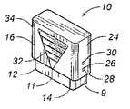
図1、図2は、本発明の好ましい実施例による皮膚切開装置10を示す。皮膚切開装置10は、底面14を有するケーシング12と該ケーシング12に摺嵌されるカバー16とを備えている。トップカバー16は、底面14の面を横切る方向に摺動する。ケーシング12は、第一パネル9と第二パネル11とを備えている。 1 and 2 show a
ケーシング12は、略開口端18を底面14と反対側に有する。ケーシング12は、底面14から上方に延びる側部20、22を備えている。カバー16は、ケーシング12の開口端18上に位置し、ケーシング12の側部20の少なくとも一部上に位置する壁部24を備えている。側部20は、該側部から外方に突出する突起26を備えている。壁部24は、第一保持孔28と、該第一保持孔28の上方に形成された第二保持孔30とを備えている。図1に示すように、突起26は第一保持孔28に係合する。 The
図1においては、装置10は作動前の位置にある。最終的には、底面14は皮膚の表面に当接し、カバー16は底面14に向かって下方に押圧される。その結果、突起26は第一保持孔28から離脱する。装置10が皮膚を切開し、ブレードが作動後の位置に保持される時には、突起26は第二保持孔30内に保持される。その結果、突起26は装置10の再使用を防止する。本発明の思想においては、図3〜図5に示すように、カバー16の反対側の壁部34に形成された第一保持孔37と第二保持孔39とに摺動係合するように別の突起42をケーシング12の反対側の側部22にも配設することができる。 In FIG. 1, the
図1、図2に示すカバー16には、装置10を把持するために使用することができる三角形状の突出部32が設けられている。突出部32の三角形状はレーザーブレード38の動きの中心線を示している。突出部32はカバー16の反対側にも同様に配設してもよい。図示のケーシング12は該ケーシング12の開口端18から延びる複数本の突条35を備えている。該突条35は、ケーシング12に沿ったカバー16の下方向への動きを案内し、規制する。カバー16の内面には該突条35に係合してケーシング12を規制する対応構造を備えさせてもよい。 The
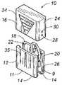
図3〜図5は、本発明による装置10の内部構造と構成要素とを、作動前の位置(図3)から中間位置(図4)、作動後の位置(図5)まで、連続的に示す。図3〜図5の各図は、ケーシング12内に配設されている本発明のブレード38とアクチュエータ46とキャリッジ58とを示している。図3〜図5はケーシング12の第一パネル9を示し、図6はケーシング12の第二パネル11を示す。 3 to 5 show the internal structure and components of the
特に、図3〜図5において、ケーシング12はその底面14に形成された孔36を備えていることが示されている。ケーシング12の内部40には孔36と底面14とに近接させた状態で破線に示すブレード38が配設されている。また、ケーシング12は、底面14から上方に延びる側部20と、底面14から上方に延びる別の側部22とを備えている。ケーシング12の側部20には突起26が設けられている。ケーシング12の側部22には別の突起42が設けられている。カバー16は破線により示されている。 In particular, FIGS. 3-5 show that the
図1に示すように、突起26は、カバー16の壁部24における第一保持孔28に係合している。突起42は、カバー16の壁部34における対応する第一保持孔37に係合している。その結果、カバー16は作動前の位置にある。 As shown in FIG. 1, the
図3〜図5において、ケーシング12は、該ケーシング12の内面と一体的に形成されたリリースシート13と、案内部材15と、キャプチャーシート17とを備えている。リリースシート13は、ブレード38が作動前の位置(図3)にある時にアクチュエータ46のナックル56を保持する。案内部材15は、キャプチャーシート17と一体の略L字状部材として示されている。しかしながら、案内部材15は、実際にはこのL字状部材の端面であり、該端面にカム64の表面が当接する。案内部材15の該端面は、ブレード38が作動前の位置から作動後の位置(図4)に移動する時に、キャリッジ58のカム64に摺接する。キャプチャーシート17は、アクチュエータ46のナックル56を作動後の位置(図5)に保持する。アクチュエータ46のナックル56は、アクチュエータ46を再使用のために再びセットすることを防止するように、キャプチャーシート17に保持される。突起26と保持孔30との協同及び突起42と保持孔39との協同も再使用を防止する。ケーシング12の内部40には別のロック部材を配設してもよい。 3 to 5, the
図3〜図5に示すケーシング12は、ケーシング12の内面と一体的に形成され、かつ、ケーシング12の開口端18に近接して配設されている支持部材19を備えている。ブレード38が作動前の位置から作動後の位置に動く時におけるカバー16の移動中に、支持部材19はケーシング12内におけるアクチュエータ46の幹部41に摺接する。支持部材19は、平行な間隔で配設された一対の平行なブロックの形状をとる。幹部は、該幹部が支持部材19から上方へ動くことを防止するように、該幹部の端部に膨出頭部43を備えている。この構成により、ケーシング12内におけるアクチュエータ46の取付と組立が容易になる。特に、幹部41を支持部材19内に保持することによりアクチュエータ46を作動前の形状に取り付けることができる。 The
図6に示すように、本発明の皮膚切開装置10は、第一パネル9(図3〜図5に示す。)と第二パネル11(図6)とを接合させてなるケーシング12を備えている。第二パネル11は、第一パネル9に固着され、第一パネル9と第二パネル11との各底面14にてこれらのパネル間に孔36を形成する。ケーシング12の構造物は、各側部20、22の突起26、42を含め、第一パネル9と第二パネル11とのいずれに配設してもよい。第二パネル11は、パネル9、11を接合し、その中に室又は内部容積40を確保するように、第一パネル9のピン穴7に挿嵌されるピン5を備えている。図6は、作動前の位置から作動後の位置までの水平移動中における第二ケーシング11内のブレード38を破線で示すものであり、図4における第一ケーシング9の図に対応するものである。 As shown in FIG. 6, the
図3〜図5において、アクチュエータ46はカバー16の内面63と協同する上縁48を備えている。作動前の位置(図3)から作動後の位置(図5)までのブレード38の移動中、該上縁48はカバー16の内面63に当接している。アクチュエータ46は、ケーシング12の開口端18を通って曲った状態で下方に延びる弾性湾曲部材45(リーフスプリング状をなす。)を備えている。アクチュエータ46における反対側の終端にはナックル56が形成されている。アクチュエータ46は、皮膚切開法に要求されるより大きな又はより小さな力に適合させるために、適宜、変更し、交換し、修正し、又は他の方法で手を加えてもよい。一般に、弾性湾曲部材45の厚さとアクチュエータ46の材料選択は、ブレード38を作動させるための力のしきい値をコントロールする。 3 to 5, the
図3に示すようにブレード38がリリースシート13において作動前の位置にある時には、ナックル56はケーシング12により固定されている。弾性部材45は、リリースシート13の上縁に接触するように外方に曲る。この接触により、ナックル56はリリースシート13上面のノッチ65から上方に押し出される。ブレード38が作動前の位置から図4に示す作動後の位置まで動く間、ナックル56はブレード38の縁67に接触する。同時に、図6に示すように、ナックル移動ポケット49がケーシング12の第二パネル11と一体的に形成されている。ナックル移動ポケット49は、リリースシート13からキャプチャーシート17までのナックルの動きを案内する。アクチュエータ46は、ナックル56と弾性部材45がカム64等のケーシング12内の他の構造物まで延びることをナックル移動ポケット49を利用して阻止させることにより、内部40内の他の構造物と干渉することが防止される。結局、ケーシング12は、図5に示すキャプチャーシート17における作動後の位置にナックル56を保持する。 As shown in FIG. 3, the
キャリッジ58は、ケーシング12内で特殊な形状を備えている。特に、キャリッジ58は、ケーシング12に回動自在に取り付けられた基端60と、該基端60から延びる湾曲部材62と、該湾曲部材62の先端に設けられたカム64とを備えている。カム64は、回動点108にてブレード38に回動自在に取り付けられ、孔36及び図3に示す作動前の位置からのブレード38の外方への動きを案内する。カム64は、図4に示すように、カム64の面104をケーシング12の案内部材15の底面に摺接させることにより、ブレードの外方への動きの後、ブレード38の水平方向への動きを引き起こす。また、カム64は、孔36方向への図5の作動後の位置までのブレード38の内方への動きを案内する。湾曲部材62は、ブレード38を孔36の内方へ垂直に弾性的に引っ込ませる弾性部材であってもよい。カム64は、典型的には、ブレード38に取り付けられた回動ピン108を中心として回動する曲面形状を備えている。 The
図7は、本発明による皮膚切開装置10におけるキャリッジ58のカム64の部分拡大斜視図である。カム64は該カム64の一端に回動ピン108を備えており、該回動ピンはブレード38の保持孔78に回動自在に取り付けられている。カム64は、作動前の位置における案内部材15との面接触を行なう平らな裏面106と、ブレード38の軌跡に対応する湾曲した上面104と、作動後の位置における案内部材15からカム64を引き離す平らな前面102とを備えている。その結果、カム64は、ブレード38を引き上げ、再使用のためにブレード38を作動前の位置に再びセットすることを防止する。平らな前面102は、案内部材15の背部に存する。 FIG. 7 is a partially enlarged perspective view of the
ブレード38は、該ブレード38の下端に形成された刃77を備えたレーザー部材76を含む。更に、保持孔78がブレード38の反対側の端に近接させた状態で設けられ、キャリッジ58のカム64から延びる回動ピン108が該保持孔78内に協同的に収納されている。キャリッジ58は、作動前の位置と作動後の位置との間でレーザー部材76の動きを案内する。ブレード38は、更に、ブレード38の保持孔78とレーザー部材76との間に長孔80を備えている。長孔80は、ブレード38を保持するためにケーシング12に回動自在に取り付けられている。ケーシング12は、該ケーシングの孔36の付近に形成されたブレード保持ペグ82を備えている。ブレード38の長孔80は、ブレード38がケーシング12に対し回動自在、かつ、摺動自在に取り付けられるように、ブレード保持ペグ82上に位置している。長孔80は、ブレード保持ペグ82に対し回動自在、かつ、摺動自在になるように、ブレード38に長円形状に形成してもよい。 The
ブレード38は、ケーシング12に連結された長孔80における第一回動点と、キャリッジ58に取り付けられた保持孔78における第二回動点とを有する。第一回動点においては、ブレード38が作動前の位置から作動後の位置まで動く間、ブレード38はケーシング12に対しカム関係にあり、ケーシング12に対し回動自在である。ブレード38の第一回動点は、該ブレードに形成された長円形であってもよく、該長円形はケーシング12のブレード保持ペグ上に位置する。 The
図3〜図5は、作動前の位置と作動後の位置との間における装置10のブレード38の動きを連続的に示す。特に、図3においては、カバー16はケーシング12に対し下方に押圧されている。カバー16の内面63は、アクチュエータ46の上縁48に接触している。その結果、突起26、42は、それぞれの第一保持孔28、37から脱出し、カバー1におけるそれぞれの第二保持孔30、39に嵌ることになる。移動可能なカバー16は、下方に移動し、ブレード38の作動中、皮膚に一定の圧力を及ぼす。アクチュエータ46は、カバー16の内面63に接触し、制御された負荷限界が達成された時に作動する。 3-5 show continuously the movement of the
カバー16の下方への垂直運動中に制御された負荷限界が達成された時、図4、図6に示すように、アクチュエータ46の弾性部材45は、ケーシング12の底面14に対するカバー16の下降運動により、適宜圧縮される。アクチュエータ46の弾性湾曲部は、ナックル56がケーシングのリリースシート13から解放され、作動前の位置から水平方向に脱出するように、変形し又は膨張する。図6は、リリースシート13の上縁47に支点を有する弾性部材45の片持動作によりナックル56が上方に回動することを示している。アクチュエータ46は、弾性部材45の端部にナックル56を備え、テコの動作を行なう。ナックル56は、水平方向の動きにより、作動前の位置におけるブレード38の接触面67に係合する。ナックル56がブレード38の接触面67に接触して水平方向に動くと、作動前の位置から作動後の位置へのブレード38の動きが開始される。図6において、リリースシート13のナックル移動ポケット49は、ナックル56の動きを案内するように、ナックル56と面接触している。弾性部材45とナックル56は、カム64等のケーシング12内の構造物との干渉を防止するために、制御された通路内で膨張し又は変形する。キャリッジ58は、ブレード38に回動自在に取り付けられたカム64による運動中に該ブレード38を案内する。 When a controlled load limit is achieved during the downward vertical movement of the
ケーシング12の案内部材15に対するカム64の相互作用と、ケーシング12のブレード保持ペグ82に対するブレード38の長孔80の摺接は、極めて制御された動作により、レーザー部材76をケーシング12から押し出し、皮膚を貫通させ、ケーシング12内に戻す。ブレード38のこの制御された動作は、ブレード保持ペグ82が長孔80の一端にあり、カム64がその曲面の一端にて案内部材15に接触した状態で、レーザー部材76が皮膚に進入して切断するようになす(図3)。続いて、ブレード38は水平方向に案内されるが、長孔80の反対側の端まで摺動するブレード保持ペグ82により一定の深さが維持され、カム64の曲面と案内部材15とにより水平方向における切断の深さが協同的に維持される(図4)。皮膚から出る時のブレード38の垂直方向の切断は、カム64がケーシング12の案内部材15から離れるため、キャリッジ58の湾曲部材62の弾性ばね動作により行なわれる。作動後の位置は、ブレード保持ペグ82をブレード38における長孔80の元の一端に位置させる結果になる(図5)。 The interaction of the
出入りの両方における切断の制御された動作は、皮膚に対する損傷を最小限にとどめ、皮膚組織の好ましくない要素を切開面と血液標本とに入れることを減少させ、切開位置の急速な治癒を促進する。本発明は、ブレード38の外方への動き、水平方向の動き及び内方への動きにより、パターン化された切開をもたらす。ブレードの穿刺運動に頼る従来の装置と異なり、パターン化された切開はより標準的な分析資料を与える。切開部位における皮膚のでたらめな引裂及び不均一なブレード貫入深さは、もはや、資料分析に影響を及ぼす要素ではない。 The controlled action of cutting on both in and out minimizes damage to the skin, reduces the entry of unwanted elements of skin tissue into the incision surface and blood specimen, and promotes rapid healing of the incision location . The present invention provides a patterned incision by outward movement, horizontal movement and inward movement of the
本発明を用いることにより、設計され、制御された力を得ることができる。カバー16は、ケーシング12に対し垂直方向に動く。アクチュエータ46は、ケーシング12の支持部材19により、一端にて制止され、カバー16の内面に接触する。アクチュエータ46の他端はケーシング12のリリースシート13に接触している。カバー16は下方に進み、垂直方向に加えられる力はアクチュエータ46の弾性湾曲部材に保持され、ナックル56の水平方向の動きに変換される。動いた距離と弾性湾曲部材の曲りとの関数として得られる設計された垂直方向の所定の力で、アクチュエータ46はブレード38に接触する。図3〜図5に示すように、予め働かせた垂直方向の力は水平方向の動きの中で解放される。この解放は、弾性湾曲部材45のリーフスプリング状特性の強さにより制御される。 By using the present invention, a designed and controlled force can be obtained. The
以上説明した動作に示すように、垂直方向の力はケーシング12の内部で水平方向の動きにほぼ変換される。アクチュエータ46のナックル56はブレード38に当接して動く。ナックル56がブレード38に当接して水平方向に動く時、ブレード38の動きは該ブレード38に回動自在に取り付けられているキャリッジ58により案内される。これにより、水平方向の力は、ブレードの外方への垂直方向の動きと、ブレードの水平方向の動きと、ブレードの内方への垂直方向の動きとに変換される。ブレード38に回動自在に取り付けられているキャリッジ58とケーシング12の案内部材15との相互作用は、水平方向の力をブレード38のパターン化された動きに変換する。案内部材15と協同するカム64の曲面及びブレード保持ペグ82と協同するブレードの長孔80は、パターン化された切開を確保するように独特な工夫が凝らされている。キャリッジ58のカム64がその曲面を案内部材15に沿わせて動き始めると、ブレード38は、垂直方向に孔36の外方に動き、続いて水平方向に動き、更に孔36に向かって垂直方向に内方に動く。垂直方向の内方への動きは、キャリッジ58の湾曲部材におけるバネ作用の解放により定まる。同時に関連動作が生ずる。前述の如く、突起26、42はカバー16の壁部24、34における第二保持孔30、39に係合する。その結果、カバー16は固定された状態に保持され、装置の再使用が阻止される。装置の使用後、ナックル56をキャプチャーシート17に抑えるようにした他のロック部材をケーシング12内に配設してもよい。 As shown in the operation described above, the vertical force is substantially converted into a horizontal movement inside the
本発明の上記開示と説明は、例示的かつ説明的なものである。本発明の要旨を逸脱することなく、本発明の範囲内において、例示した構成の細部に種々の変更を加えることができる。本発明は、特許請求の範囲とその均等物によってのみ限定されるものである。 The above disclosure and description of the present invention are exemplary and explanatory. Various modifications can be made to the details of the illustrated configuration within the scope of the present invention without departing from the gist of the present invention. The present invention is limited only by the claims and the equivalents thereof.
10 皮膚切開装置
12 ケーシング
14 底面
16 カバー
38 ブレード
46 アクチュエータ
58 キャリッジDESCRIPTION OF
Claims (20)
Translated fromJapanese該ケーシングに取り付けられたカバーを備え、該カバーは該ケーシングにおける底面の面を横切る方向に摺動自在であり、
前記孔に略近接させてケーシング内に回動自在に配設されたブレードを備え、該ブレードは作動前の位置と作動後の位置とを有し、
ケーシングに取り付けられたアクチュエータ手段を備え、該アクチュエータ手段は前記カバーの前記底面方向への摺動により作動し、該アクチュエータ手段はカバーの前記横切る方向の動きを該アクチュエータ手段の水平方向の動きに変換し、該アクチュエータ手段は、作動前の位置と作動後の位置との間の動きにおいて少なくともブレードの一部が前記孔から外方に出るように、作動前の位置から作動後の位置までブレードに係合し、更に、
前記ケーシングに配設され、かつ、ブレードに回動自在に取り付けられたキャリッジ手段を備え、該キャリッジ手段は作動前の位置から作動後の位置までブレードの動きを案内することを特徴とする、
皮膚切開装置。Provided with a casing with holes on the bottom,
A cover attached to the casing, the cover being slidable in a direction across the bottom surface of the casing;
Comprising a blade rotatably disposed in the casing substantially close to the hole, the blade having a position before operation and a position after operation;
Actuator means attached to the casing, the actuator means actuated by sliding the cover in the bottom direction, the actuator means converting the transverse movement of the cover into the horizontal movement of the actuator means And the actuator means moves the blade from the pre-operating position to the post-operating position so that at least a portion of the blade exits from the hole in the movement between the pre-operation position and the post-operation position. Engage, and
Carriage means disposed in the casing and rotatably attached to the blade, the carriage means guides the movement of the blade from a position before operation to a position after operation.
Skin incision device.
第一パネルと、該第一パネルに固着された第二パネルとを備え、
該第一パネルと第二パネルとにより前記孔を形成することを特徴とする請求項1に記載の皮膚切開装置。The casing is
A first panel and a second panel fixed to the first panel;
The skin incision device according to claim 1, wherein the hole is formed by the first panel and the second panel.
刃を持つレーザー部材を備え、
ブレードの一端近傍に配設された保持孔を備え、前記キャリッジ手段は、作動前の位置と作動後の位置との間でレーザー部材を回動させるように、該保持孔に協同的に接続され、更に、
ブレードの他端近傍に配設された長孔を備え、該長孔はケーシングに回動自在に接続されていることを特徴とする請求項1に記載の皮膚切開装置。The blade is
It has a laser member with a blade,
A holding hole is provided near one end of the blade, and the carriage means is cooperatively connected to the holding hole so as to rotate the laser member between a position before operation and a position after operation. In addition,
The skin incision device according to claim 1, further comprising a long hole disposed near the other end of the blade, wherein the long hole is rotatably connected to the casing.
前記ブレードが作動前の位置から作動後の位置まで動く間、前記内面に当接する上縁を備え、
該上縁から下方に延びる弾性湾曲部材を備え、
該湾曲部材の終端に配設されたナックルを備え、該ナックルはブレードが作動前の位置にある時に前記ケーシングにより固定され、該ナックルはブレードが作動前の位置から作動後の位置まで動く間ブレードに係合することを特徴とする請求項1に記載の皮膚切開装置。The actuator means includes
An upper edge that contacts the inner surface while the blade moves from a position before operation to a position after operation;
An elastic bending member extending downward from the upper edge;
A knuckle disposed at an end of the bending member, the knuckle being secured by the casing when the blade is in a pre-operation position, the knuckle being a blade while the blade moves from a pre-operation position to a post-operation position The skin incision device according to claim 1, wherein the skin incision device is engaged with the skin incision device.
前記ケーシングに取り付けられた基端を備え、
該基端から延びる湾曲部材を備え、
該湾曲部材の終端に設けられ、かつ、ブレードに回動自在に取り付けられたカム手段を備え、該カム手段は前記孔を通してのブレードの外方への動きを案内し、当該外方への動きの後、ブレードを水平方向に動かし、更に該孔を通してのブレードの内方への動きを案内することを特徴とする請求項1に記載の皮膚切開装置。The carriage means includes
Comprising a proximal end attached to the casing;
A curved member extending from the proximal end,
Cam means provided at the end of the bending member and rotatably attached to the blade, the cam means guides the outward movement of the blade through the hole, and the outward movement 2. The skin incision device according to claim 1, wherein the blade is moved in the horizontal direction and further guides the inward movement of the blade through the hole.
該ケーシングに取り付けられたカバーを備え、該カバーは該ケーシングにおける底面の面を横切る方向に摺動自在であり、
前記孔に略近接させてケーシング内に回動自在に配設されたブレードを備え、該ブレードは作動前の位置と作動後の位置とを有し、
前記カバーの内面と協同する端を有し、かつ、ケーシング内に下方に延びるアクチュエータを備え、更に、
前記ケーシング内に配設され、かつ、ブレードに回動自在に取り付けられたキャリッジ手段を備え、前記アクチュエータは作動前の位置から作動後の位置までブレードと協同し、前記キャリッジ手段は作動前の位置と作動後の位置との間でブレードを案内するためにケーシング内で移動することを特徴とする、
皮膚切開装置。Provided with a casing with holes on the bottom,
A cover attached to the casing, the cover being slidable in a direction across the bottom surface of the casing;
Comprising a blade rotatably disposed in the casing substantially close to the hole, the blade having a position before operation and a position after operation;
An actuator having an end cooperating with the inner surface of the cover and extending downward into the casing;
Carriage means disposed in the casing and pivotably attached to the blade, wherein the actuator cooperates with the blade from a pre-operation position to a post-operation position, and the carriage means is in a pre-operation position. And moving in the casing to guide the blade between the position after operation and
Skin incision device.
前記ケーシングに回動自在に取り付けられた基端を有する湾曲部材を備え、
該湾曲部材の終端に形成され、かつ、ブレードに回動自在に取り付けられたカム面を備え、前記カム面は、作動前の位置からの前記孔を通してのブレードの外方への動きの間、当該外方への動きの後のブレードの水平方向への動きの間、及び前記孔を通しての作動後の位置までのブレードの内方への動きの間、前記ケーシングと協同することを特徴とする請求項16に記載の皮膚切開装置。The carriage means includes
A curved member having a proximal end pivotably attached to the casing;
A cam surface formed at the end of the curved member and pivotally attached to the blade, the cam surface during the outward movement of the blade through the hole from a pre-operational position; Cooperating with the casing during the horizontal movement of the blade after the outward movement and during the inward movement of the blade to the position after actuation through the hole The skin incision device according to claim 16.
前記ブレードは、
刃を持つレーザー部材を備え、
ブレードの一端近傍に配設された保持孔を備え、前記キャリッジ手段は、作動前の位置と作動後の位置との間でレーザー部材を回動させるように、該保持孔に協同的に接続され、更に、
ブレードの他端近傍に配設された長孔を備え、該長孔はケーシングのブレード保持ペグに回動自在に取り付けられていることを特徴とする請求項16に記載の皮膚切開装置。The casing includes a blade holding peg formed therein,
The blade is
It has a laser member with a blade,
A holding hole is provided near one end of the blade, and the carriage means is cooperatively connected to the holding hole so as to rotate the laser member between a position before operation and a position after operation. In addition,
The skin incision device according to claim 16, further comprising a long hole disposed near the other end of the blade, wherein the long hole is rotatably attached to a blade holding peg of the casing.
該ケーシングに取り付けられたカバーを備え、該カバーは該ケーシングにおける底面の面を横切る方向に摺動自在であり、該ケーシングは底面と反対側に略開口端を有し、該ケーシングは該底面から上方に延びる側部を有し、該ケーシングにおける少なくとも一側部は外方に突出する突起を有し、該カバーはケーシングの側部の一部上に延びる壁部を有し、該壁部は該壁部内に形成された第一保持孔と、該壁部内における第一保持孔の上方に形成された第二保持孔とを有し、
前記ケーシングの底面に略近接させてケーシング内に回動自在に配設されたブレードを備え、該ブレードは作動前の位置と作動後の位置とを有し、前記突起は、ブレードが作動前の位置にある時には、第一保持孔に係合し、前記突起は、ブレードが作動後の位置にある時には、第二保持孔に係合し、
ケーシング内に配設され、かつ、前記カバーの前記底面方向への摺動により作動するアクチュエータ手段を備え、該アクチュエータ手段はカバーの前記横切る方向の動きを該アクチュエータ手段の水平方向の動きに変換し、該アクチュエータ手段は、作動前の位置と作動後の位置との間の動きにおいて少なくともブレードの一部が前記孔から外方に出るように、作動前の位置から作動後の位置までブレードに係合し、更に、
前記ケーシングに配設され、かつ、ブレードに回動自在に取り付けられたキャリッジ手段を備え、該キャリッジ手段は作動前の位置から作動後の位置までブレードの動きを案内することを特徴とする、
皮膚切開装置。Provided with a casing with holes on the bottom,
A cover attached to the casing, the cover being slidable in a direction transverse to a bottom surface of the casing, the casing having a substantially open end opposite to the bottom surface, and the casing extending from the bottom surface; Having a side portion extending upward, at least one side of the casing having an outwardly projecting protrusion, the cover having a wall portion extending over a portion of the side portion of the casing, the wall portion being A first holding hole formed in the wall and a second holding hole formed above the first holding hole in the wall;
A blade disposed in the casing so as to be rotatable in substantially close proximity to a bottom surface of the casing, the blade having a pre-operation position and a post-operation position; When in the position, it engages with the first holding hole, and when the blade is in the post-operation position, the projection engages with the second holding hole,
Actuator means disposed in the casing and operated by sliding the cover toward the bottom surface, the actuator means converting the transverse movement of the cover into the horizontal movement of the actuator means. The actuator means engages the blade from a pre-operating position to a post-operating position such that at least a portion of the blade exits from the hole during movement between the pre-operating position and the post-operating position In addition,
Carriage means disposed in the casing and rotatably attached to the blade, the carriage means guides the movement of the blade from a position before operation to a position after operation.
Skin incision device.
Applications Claiming Priority (2)
| Application Number | Priority Date | Filing Date | Title |
|---|---|---|---|
| US10/792,025US7160313B2 (en) | 2003-07-28 | 2004-03-03 | Load-controlled device for a patterned skin incision |
| PCT/US2005/005933WO2005091878A2 (en) | 2004-03-03 | 2005-02-25 | Load-controlled device for a patterned skin incision |
Publications (1)
| Publication Number | Publication Date |
|---|---|
| JP2007526082Atrue JP2007526082A (en) | 2007-09-13 |
Family
ID=35056663
Family Applications (1)
| Application Number | Title | Priority Date | Filing Date |
|---|---|---|---|
| JP2007501843APendingJP2007526082A (en) | 2004-03-03 | 2005-02-25 | Load control device for patterned skin incision |
Country Status (8)
| Country | Link |
|---|---|
| US (2) | US7160313B2 (en) |
| EP (1) | EP1737359A4 (en) |
| JP (1) | JP2007526082A (en) |
| AU (1) | AU2005227179B2 (en) |
| CA (1) | CA2556524C (en) |
| DE (1) | DE05723695T1 (en) |
| ES (1) | ES2307464T1 (en) |
| WO (1) | WO2005091878A2 (en) |
Cited By (3)
| Publication number | Priority date | Publication date | Assignee | Title |
|---|---|---|---|---|
| JP2015516854A (en)* | 2012-04-20 | 2015-06-18 | メディパーパス ピーティーイー リミテッド | Lancet |
| JP2015519171A (en)* | 2012-06-12 | 2015-07-09 | ティ − メディカル・イノベーションズ・リミテッドT − Medical Innovations Ltd. | Device and method for making an initial skin incision in a surgical operation and method for marking along the edge of an incision |
| JP2016032774A (en)* | 2011-02-14 | 2016-03-10 | 株式会社旭ポリスライダー | Lancet device |
Families Citing this family (101)
| Publication number | Priority date | Publication date | Assignee | Title |
|---|---|---|---|---|
| US6036924A (en)* | 1997-12-04 | 2000-03-14 | Hewlett-Packard Company | Cassette of lancet cartridges for sampling blood |
| US6391005B1 (en) | 1998-03-30 | 2002-05-21 | Agilent Technologies, Inc. | Apparatus and method for penetration with shaft having a sensor for sensing penetration depth |
| US7175641B1 (en) | 1998-06-11 | 2007-02-13 | Stat Medical Devices, Inc. | Lancet having adjustable penetration depth |
| US8641644B2 (en) | 2000-11-21 | 2014-02-04 | Sanofi-Aventis Deutschland Gmbh | Blood testing apparatus having a rotatable cartridge with multiple lancing elements and testing means |
| DE10057832C1 (en) | 2000-11-21 | 2002-02-21 | Hartmann Paul Ag | Blood analysis device has syringe mounted in casing, annular mounting carrying needles mounted behind test strip and being swiveled so that needle can be pushed through strip and aperture in casing to take blood sample |
| AU2002344825A1 (en)* | 2001-06-12 | 2002-12-23 | Pelikan Technologies, Inc. | Method and apparatus for improving success rate of blood yield from a fingerstick |
| US7981056B2 (en) | 2002-04-19 | 2011-07-19 | Pelikan Technologies, Inc. | Methods and apparatus for lancet actuation |
| JP4209767B2 (en) | 2001-06-12 | 2009-01-14 | ペリカン テクノロジーズ インコーポレイテッド | Self-optimized cutting instrument with adaptive means for temporary changes in skin properties |
| WO2002101359A2 (en) | 2001-06-12 | 2002-12-19 | Pelikan Technologies, Inc. | Integrated blood sampling analysis system with multi-use sampling module |
| JP4272051B2 (en)* | 2001-06-12 | 2009-06-03 | ペリカン テクノロジーズ インコーポレイテッド | Blood sampling apparatus and method |
| US7344507B2 (en) | 2002-04-19 | 2008-03-18 | Pelikan Technologies, Inc. | Method and apparatus for lancet actuation |
| US7041068B2 (en)* | 2001-06-12 | 2006-05-09 | Pelikan Technologies, Inc. | Sampling module device and method |
| EP1395185B1 (en) | 2001-06-12 | 2010-10-27 | Pelikan Technologies Inc. | Electric lancet actuator |
| US9795747B2 (en) | 2010-06-02 | 2017-10-24 | Sanofi-Aventis Deutschland Gmbh | Methods and apparatus for lancet actuation |
| US7749174B2 (en) | 2001-06-12 | 2010-07-06 | Pelikan Technologies, Inc. | Method and apparatus for lancet launching device intergrated onto a blood-sampling cartridge |
| US8337419B2 (en) | 2002-04-19 | 2012-12-25 | Sanofi-Aventis Deutschland Gmbh | Tissue penetration device |
| US9427532B2 (en) | 2001-06-12 | 2016-08-30 | Sanofi-Aventis Deutschland Gmbh | Tissue penetration device |
| US9226699B2 (en) | 2002-04-19 | 2016-01-05 | Sanofi-Aventis Deutschland Gmbh | Body fluid sampling module with a continuous compression tissue interface surface |
| US7344894B2 (en) | 2001-10-16 | 2008-03-18 | Agilent Technologies, Inc. | Thermal regulation of fluidic samples within a diagnostic cartridge |
| US7371247B2 (en)* | 2002-04-19 | 2008-05-13 | Pelikan Technologies, Inc | Method and apparatus for penetrating tissue |
| US7229458B2 (en) | 2002-04-19 | 2007-06-12 | Pelikan Technologies, Inc. | Method and apparatus for penetrating tissue |
| US9795334B2 (en) | 2002-04-19 | 2017-10-24 | Sanofi-Aventis Deutschland Gmbh | Method and apparatus for penetrating tissue |
| US8267870B2 (en) | 2002-04-19 | 2012-09-18 | Sanofi-Aventis Deutschland Gmbh | Method and apparatus for body fluid sampling with hybrid actuation |
| US7582099B2 (en) | 2002-04-19 | 2009-09-01 | Pelikan Technologies, Inc | Method and apparatus for penetrating tissue |
| US7674232B2 (en) | 2002-04-19 | 2010-03-09 | Pelikan Technologies, Inc. | Method and apparatus for penetrating tissue |
| US7648468B2 (en) | 2002-04-19 | 2010-01-19 | Pelikon Technologies, Inc. | Method and apparatus for penetrating tissue |
| US7524293B2 (en) | 2002-04-19 | 2009-04-28 | Pelikan Technologies, Inc. | Method and apparatus for penetrating tissue |
| US7232451B2 (en) | 2002-04-19 | 2007-06-19 | Pelikan Technologies, Inc. | Method and apparatus for penetrating tissue |
| US7563232B2 (en)* | 2002-04-19 | 2009-07-21 | Pelikan Technologies, Inc. | Method and apparatus for penetrating tissue |
| US7491178B2 (en) | 2002-04-19 | 2009-02-17 | Pelikan Technologies, Inc. | Method and apparatus for penetrating tissue |
| US7331931B2 (en) | 2002-04-19 | 2008-02-19 | Pelikan Technologies, Inc. | Method and apparatus for penetrating tissue |
| US7297122B2 (en) | 2002-04-19 | 2007-11-20 | Pelikan Technologies, Inc. | Method and apparatus for penetrating tissue |
| US9248267B2 (en) | 2002-04-19 | 2016-02-02 | Sanofi-Aventis Deustchland Gmbh | Tissue penetration device |
| US7481776B2 (en)* | 2002-04-19 | 2009-01-27 | Pelikan Technologies, Inc. | Method and apparatus for penetrating tissue |
| US7717863B2 (en) | 2002-04-19 | 2010-05-18 | Pelikan Technologies, Inc. | Method and apparatus for penetrating tissue |
| US7547287B2 (en) | 2002-04-19 | 2009-06-16 | Pelikan Technologies, Inc. | Method and apparatus for penetrating tissue |
| US7976476B2 (en)* | 2002-04-19 | 2011-07-12 | Pelikan Technologies, Inc. | Device and method for variable speed lancet |
| US8221334B2 (en) | 2002-04-19 | 2012-07-17 | Sanofi-Aventis Deutschland Gmbh | Method and apparatus for penetrating tissue |
| US8784335B2 (en) | 2002-04-19 | 2014-07-22 | Sanofi-Aventis Deutschland Gmbh | Body fluid sampling device with a capacitive sensor |
| US7901362B2 (en) | 2002-04-19 | 2011-03-08 | Pelikan Technologies, Inc. | Method and apparatus for penetrating tissue |
| US7374544B2 (en) | 2002-04-19 | 2008-05-20 | Pelikan Technologies, Inc. | Method and apparatus for penetrating tissue |
| US7410468B2 (en)* | 2002-04-19 | 2008-08-12 | Pelikan Technologies, Inc. | Method and apparatus for penetrating tissue |
| US7141058B2 (en)* | 2002-04-19 | 2006-11-28 | Pelikan Technologies, Inc. | Method and apparatus for a body fluid sampling device using illumination |
| US7892183B2 (en) | 2002-04-19 | 2011-02-22 | Pelikan Technologies, Inc. | Method and apparatus for body fluid sampling and analyte sensing |
| US9314194B2 (en) | 2002-04-19 | 2016-04-19 | Sanofi-Aventis Deutschland Gmbh | Tissue penetration device |
| US8579831B2 (en) | 2002-04-19 | 2013-11-12 | Sanofi-Aventis Deutschland Gmbh | Method and apparatus for penetrating tissue |
| US7708701B2 (en) | 2002-04-19 | 2010-05-04 | Pelikan Technologies, Inc. | Method and apparatus for a multi-use body fluid sampling device |
| US7909778B2 (en) | 2002-04-19 | 2011-03-22 | Pelikan Technologies, Inc. | Method and apparatus for penetrating tissue |
| US8702624B2 (en) | 2006-09-29 | 2014-04-22 | Sanofi-Aventis Deutschland Gmbh | Analyte measurement device with a single shot actuator |
| US7291117B2 (en) | 2002-04-19 | 2007-11-06 | Pelikan Technologies, Inc. | Method and apparatus for penetrating tissue |
| US8574895B2 (en) | 2002-12-30 | 2013-11-05 | Sanofi-Aventis Deutschland Gmbh | Method and apparatus using optical techniques to measure analyte levels |
| WO2004060174A2 (en)* | 2002-12-31 | 2004-07-22 | Pelikan Technologies Inc. | Method and apparatus for loading penetrating members |
| US7850621B2 (en) | 2003-06-06 | 2010-12-14 | Pelikan Technologies, Inc. | Method and apparatus for body fluid sampling and analyte sensing |
| WO2006001797A1 (en) | 2004-06-14 | 2006-01-05 | Pelikan Technologies, Inc. | Low pain penetrating |
| EP1635700B1 (en) | 2003-06-13 | 2016-03-09 | Sanofi-Aventis Deutschland GmbH | Apparatus for a point of care device |
| US7160313B2 (en)* | 2003-07-28 | 2007-01-09 | Helena Laboratories | Load-controlled device for a patterned skin incision |
| US7452365B2 (en)* | 2003-07-28 | 2008-11-18 | Helena Laboratories | Load-controlled device for a patterned skin incision of constant depth |
| US7905898B2 (en)* | 2003-08-15 | 2011-03-15 | Stat Medical Devices, Inc. | Adjustable lancet device and method |
| US8282576B2 (en) | 2003-09-29 | 2012-10-09 | Sanofi-Aventis Deutschland Gmbh | Method and apparatus for an improved sample capture device |
| EP1680014A4 (en) | 2003-10-14 | 2009-01-21 | Pelikan Technologies Inc | METHOD AND DEVICE FOR A VARIABLE USER INTERFACE |
| US8668656B2 (en) | 2003-12-31 | 2014-03-11 | Sanofi-Aventis Deutschland Gmbh | Method and apparatus for improving fluidic flow and sample capture |
| US7822454B1 (en) | 2005-01-03 | 2010-10-26 | Pelikan Technologies, Inc. | Fluid sampling device with improved analyte detecting member configuration |
| US7662176B2 (en) | 2004-02-19 | 2010-02-16 | Vomaris Innovations, Inc. | Footwear apparatus and methods of manufacture and use |
| US7457667B2 (en)* | 2004-02-19 | 2008-11-25 | Silverleaf Medical Products, Inc. | Current producing surface for a wound dressing |
| WO2005084557A1 (en)* | 2004-03-02 | 2005-09-15 | Facet Technologies, Llc | Compact multi-use lancing device |
| WO2006011062A2 (en) | 2004-05-20 | 2006-02-02 | Albatros Technologies Gmbh & Co. Kg | Printable hydrogel for biosensors |
| WO2005120365A1 (en) | 2004-06-03 | 2005-12-22 | Pelikan Technologies, Inc. | Method and apparatus for a fluid sampling device |
| US20130071837A1 (en)* | 2004-10-06 | 2013-03-21 | Stephen N. Winters-Hilt | Method and System for Characterizing or Identifying Molecules and Molecular Mixtures |
| DE102004058164B4 (en)* | 2004-12-02 | 2009-04-16 | Roche Diagnostics Gmbh | Lancing device for taking blood and method for the preparation thereof |
| US8652831B2 (en) | 2004-12-30 | 2014-02-18 | Sanofi-Aventis Deutschland Gmbh | Method and apparatus for analyte measurement test time |
| WO2006110572A2 (en)* | 2005-04-07 | 2006-10-19 | Becton, Dickinson And Company | Finger activated lancet device |
| WO2006110573A1 (en)* | 2005-04-07 | 2006-10-19 | Becton, Dickinson And Company | Trigger activated lancet |
| US7775991B2 (en)* | 2005-08-31 | 2010-08-17 | Kimberly-Clark Worldwide, Inc. | Device for sampling blood |
| US7704265B2 (en) | 2005-11-03 | 2010-04-27 | Stat Medical Devices, Inc. | Disposable/single-use blade lancet device and method |
| US20080122582A1 (en)* | 2006-11-29 | 2008-05-29 | Texas Instruments Incorporated | Location Based Portable Device Feature Disabler |
| EP2265324B1 (en) | 2008-04-11 | 2015-01-28 | Sanofi-Aventis Deutschland GmbH | Integrated analyte measurement system |
| US8043316B2 (en)* | 2008-05-02 | 2011-10-25 | Suros Surgical Systems, Inc. | Adjustable spacer |
| JP2010148694A (en)* | 2008-12-25 | 2010-07-08 | Nissei Plastics Ind Co | Puncture device |
| US9375169B2 (en) | 2009-01-30 | 2016-06-28 | Sanofi-Aventis Deutschland Gmbh | Cam drive for managing disposable penetrating member actions with a single motor and motor and control system |
| US8012770B2 (en) | 2009-07-31 | 2011-09-06 | Invisible Sentinel, Inc. | Device for detection of antigens and uses thereof |
| US9475049B2 (en) | 2009-07-31 | 2016-10-25 | Invisible Sentinel, Inc. | Analyte detection devices, multiplex and tabletop devices for detection of analyte, and uses thereof |
| WO2011044574A1 (en) | 2009-10-09 | 2011-04-14 | Invisible Sentinel | Device for detection of antigens and uses thereof |
| US8512367B2 (en)* | 2009-12-16 | 2013-08-20 | Facet Technologies, Llc | Blood sampling device with dual-link drive mechanism |
| US8965476B2 (en) | 2010-04-16 | 2015-02-24 | Sanofi-Aventis Deutschland Gmbh | Tissue penetration device |
| SG182858A1 (en)* | 2011-01-07 | 2012-08-30 | Wah Leong Lum | Contact activated incision device |
| US20130211289A1 (en) | 2012-01-25 | 2013-08-15 | Tasso, Inc. | Handheld Device for Drawing, Collecting, and Analyzing Bodily Fluid |
| GB2498772A (en)* | 2012-01-27 | 2013-07-31 | Owen Mumford Ltd | Lancing device moving lancet needle in longitudinal and lateral directions, lancet needle and lancing device with anti-recocking means |
| US9238836B2 (en) | 2012-03-30 | 2016-01-19 | Pacific Biosciences Of California, Inc. | Methods and compositions for sequencing modified nucleic acids |
| NZ629703A (en) | 2012-03-09 | 2016-05-27 | Invisible Sentinel Inc | Methods and compositions for detecting multiple analytes with a single signal |
| EP2836125B1 (en) | 2012-04-12 | 2016-06-08 | Facet Technologies, LLC | Lancing device with side activated charge and eject mechanisms |
| JP6429770B2 (en) | 2012-06-18 | 2018-11-28 | ファセット テクノロジーズ エルエルシーFacet Technologies, LLC | One-way drive mechanism for puncture device |
| US10732183B2 (en)* | 2013-03-15 | 2020-08-04 | The Trustees Of Columbia University In The City Of New York | Method for detecting multiple predetermined compounds in a sample |
| USD742004S1 (en) | 2014-02-18 | 2015-10-27 | “HTL-STREFA” Spólka Akcyjna | Skin incision device |
| US10172613B1 (en)* | 2014-07-10 | 2019-01-08 | Dallen Medical, Inc. | Pre-loaded, disposable, dynamic compression bone staple delivery devices and methods |
| CN106999120B (en) | 2014-08-01 | 2021-05-14 | 塔索公司 | Devices, systems, and methods for gravity-enhanced microfluidic collection, handling, and delivery of liquids |
| CA3009328C (en) | 2015-12-21 | 2024-03-05 | Tasso, Inc. | Devices, systems and methods for actuation and retraction in fluid collection |
| US10871467B2 (en) | 2017-12-13 | 2020-12-22 | Cannaptic Biosciences, LLC | Cannabinoid profiling using nanopore transduction |
| JP7460607B2 (en) | 2018-09-14 | 2024-04-02 | タッソ インコーポレイテッド | Body fluid collection devices and related methods |
| US12321837B2 (en)* | 2019-02-14 | 2025-06-03 | University Of Washington | Systems and methods for improved nanopore-based analysis of nucleic acids |
| AU2022227019A1 (en) | 2021-02-26 | 2023-08-31 | Tasso, Inc. | Bodily fluid collection devices and related methods |
| WO2025048725A1 (en)* | 2023-08-31 | 2025-03-06 | Dermcut Medical Pte. Ltd. | A device for skin biopsy and scar revision |
Citations (6)
| Publication number | Priority date | Publication date | Assignee | Title |
|---|---|---|---|---|
| US5314441A (en)* | 1992-10-16 | 1994-05-24 | International Technidyne Corporation | Disposable slicing lancet assembly |
| US5529581A (en)* | 1994-05-17 | 1996-06-25 | International Technidyne Corporation | Lancet device for creating a skin incision |
| JP2000511068A (en)* | 1996-05-17 | 2000-08-29 | マーキュリー ダイアグノスティックス インコーポレイテッド | Body fluid sampling device and method of using the same |
| JP2000511440A (en)* | 1996-05-23 | 2000-09-05 | アレイ メディカル インコーポレイテッド | Disposable bidirectional linear motion lancet |
| JP2001078991A (en)* | 1999-09-06 | 2001-03-27 | P Z Htl Spolka Akcyjna | Puncture instrument |
| JP2002516147A (en)* | 1998-05-22 | 2002-06-04 | スペシャライズド・ヘルス・プロダクツ・インコーポレーテッド | Lancet device and method |
Family Cites Families (18)
| Publication number | Priority date | Publication date | Assignee | Title |
|---|---|---|---|---|
| US4064871A (en) | 1976-05-11 | 1977-12-27 | Becton, Dickinson And Company | Device for making precise incisions for bleeding time testing and the like |
| US4535769A (en) | 1981-03-23 | 1985-08-20 | Becton, Dickinson And Company | Automatic retractable lancet assembly |
| US4643189A (en) | 1985-02-19 | 1987-02-17 | W. T. Associates | Apparatus for implementing a standardized skin incision |
| US5395388A (en) | 1993-11-15 | 1995-03-07 | Schraga; Steven | Single unit lancet device |
| US5527333A (en) | 1994-09-09 | 1996-06-18 | Graphic Controls Corporation | Slicing disposable blood sampling device |
| US5584846A (en) | 1995-10-27 | 1996-12-17 | International Technidyne Corporation | Low cost disposable lancet |
| US5851215A (en) | 1996-09-24 | 1998-12-22 | International Technidyne Corporation | Low cost disposable lancet |
| US5782852A (en)* | 1996-09-27 | 1998-07-21 | International Technidyne Corporation | Plastic incision blade |
| US5797940A (en) | 1997-05-30 | 1998-08-25 | International Technidyne Corporation | Adjustable skin incision device |
| US6221089B1 (en) | 1997-07-07 | 2001-04-24 | International Technidyne Corporation | Skin incision device with compression spring assembly |
| US6180356B1 (en)* | 1998-03-06 | 2001-01-30 | The Research Foundation Of State University Of Ny | Membrane pore inhibiting agents for treating infection |
| US6426231B1 (en)* | 1998-11-18 | 2002-07-30 | The Texas A&M University System | Analyte sensing mediated by adapter/carrier molecules |
| AU5723700A (en)* | 1999-05-25 | 2000-12-12 | Praelux Incorporated | Method for sequency and characterizing polymeric biomolecules using aptamers anda method for producing aptamers |
| SG85117A1 (en) | 1999-06-18 | 2001-12-19 | Surgilance Pte Ltd | Lancet assembly |
| EP1192453B1 (en)* | 1999-06-22 | 2012-02-15 | President and Fellows of Harvard College | Molecular and atomic scale evaluation of biopolymers |
| US6358265B1 (en)* | 2000-07-18 | 2002-03-19 | Specialized Health Products, Inc. | Single-step disposable safety lancet apparatus and methods |
| WO2002042496A2 (en)* | 2000-11-27 | 2002-05-30 | The Regents Of The University Of California | Methods and devices for characterizing duplex nucleic acid molecules |
| US7160313B2 (en)* | 2003-07-28 | 2007-01-09 | Helena Laboratories | Load-controlled device for a patterned skin incision |
- 2004
- 2004-03-03USUS10/792,025patent/US7160313B2/ennot_activeExpired - Fee Related
- 2005
- 2005-02-25ESES05723695Tpatent/ES2307464T1/enactivePending
- 2005-02-25JPJP2007501843Apatent/JP2007526082A/enactivePending
- 2005-02-25DEDE05723695Tpatent/DE05723695T1/enactivePending
- 2005-02-25EPEP05723695Apatent/EP1737359A4/ennot_activeCeased
- 2005-02-25CACA002556524Apatent/CA2556524C/ennot_activeExpired - Fee Related
- 2005-02-25AUAU2005227179Apatent/AU2005227179B2/ennot_activeCeased
- 2005-02-25WOPCT/US2005/005933patent/WO2005091878A2/ennot_activeApplication Discontinuation
- 2005-10-06USUS11/576,723patent/US20090054919A2/ennot_activeAbandoned
Patent Citations (6)
| Publication number | Priority date | Publication date | Assignee | Title |
|---|---|---|---|---|
| US5314441A (en)* | 1992-10-16 | 1994-05-24 | International Technidyne Corporation | Disposable slicing lancet assembly |
| US5529581A (en)* | 1994-05-17 | 1996-06-25 | International Technidyne Corporation | Lancet device for creating a skin incision |
| JP2000511068A (en)* | 1996-05-17 | 2000-08-29 | マーキュリー ダイアグノスティックス インコーポレイテッド | Body fluid sampling device and method of using the same |
| JP2000511440A (en)* | 1996-05-23 | 2000-09-05 | アレイ メディカル インコーポレイテッド | Disposable bidirectional linear motion lancet |
| JP2002516147A (en)* | 1998-05-22 | 2002-06-04 | スペシャライズド・ヘルス・プロダクツ・インコーポレーテッド | Lancet device and method |
| JP2001078991A (en)* | 1999-09-06 | 2001-03-27 | P Z Htl Spolka Akcyjna | Puncture instrument |
Cited By (4)
| Publication number | Priority date | Publication date | Assignee | Title |
|---|---|---|---|---|
| JP2016032774A (en)* | 2011-02-14 | 2016-03-10 | 株式会社旭ポリスライダー | Lancet device |
| JP5948256B2 (en)* | 2011-02-14 | 2016-07-06 | 株式会社旭ポリスライダー | Lancet device |
| JP2015516854A (en)* | 2012-04-20 | 2015-06-18 | メディパーパス ピーティーイー リミテッド | Lancet |
| JP2015519171A (en)* | 2012-06-12 | 2015-07-09 | ティ − メディカル・イノベーションズ・リミテッドT − Medical Innovations Ltd. | Device and method for making an initial skin incision in a surgical operation and method for marking along the edge of an incision |
Also Published As
| Publication number | Publication date |
|---|---|
| US20050125018A1 (en) | 2005-06-09 |
| EP1737359A2 (en) | 2007-01-03 |
| CA2556524A1 (en) | 2005-10-06 |
| AU2005227179A1 (en) | 2005-10-06 |
| CA2556524C (en) | 2009-12-22 |
| US7160313B2 (en) | 2007-01-09 |
| ES2307464T1 (en) | 2008-12-01 |
| US20080097502A1 (en) | 2008-04-24 |
| EP1737359A4 (en) | 2010-07-28 |
| US20090054919A2 (en) | 2009-02-26 |
| DE05723695T1 (en) | 2008-09-25 |
| WO2005091878A2 (en) | 2005-10-06 |
| WO2005091878A3 (en) | 2007-07-05 |
| AU2005227179B2 (en) | 2010-02-11 |
Similar Documents
| Publication | Publication Date | Title |
|---|---|---|
| JP2007526082A (en) | Load control device for patterned skin incision | |
| US7452365B2 (en) | Load-controlled device for a patterned skin incision of constant depth | |
| US4643189A (en) | Apparatus for implementing a standardized skin incision | |
| US6221089B1 (en) | Skin incision device with compression spring assembly | |
| US5571132A (en) | Self activated finger lancet | |
| US5212879A (en) | Method for manufacturing a disposable-retractable finger stick device | |
| US5476474A (en) | Rotary lancet | |
| US4064871A (en) | Device for making precise incisions for bleeding time testing and the like | |
| JP3214069U (en) | Stapling head assembly and endoscopic surgical suture cutting device | |
| EP1868501B1 (en) | Finger activated lancet device | |
| US4559041A (en) | Cannula introducers | |
| US7704265B2 (en) | Disposable/single-use blade lancet device and method | |
| CN101711678B (en) | Contact actuated lancet device | |
| US5314441A (en) | Disposable slicing lancet assembly | |
| US20210059588A1 (en) | Bodily fluid collection devices and related methods | |
| EP1033109B1 (en) | Lancet apparatus for producing a precisely controlled incision | |
| BRPI0609637A2 (en) | trigger activated lancet | |
| US7316698B1 (en) | Load-controlled auto-actuated skin incision device | |
| JP2000511440A (en) | Disposable bidirectional linear motion lancet | |
| US20150209068A1 (en) | Lancet Assembly | |
| US8105347B2 (en) | Adjustable disposable/single-use blade lancet device and method | |
| KR20080038419A (en) | Patient skin puncture | |
| JPH10506558A (en) | Retractable safety penetrator with safety probe | |
| CN211131185U (en) | Shell and biopsy needle | |
| CN101612045A (en) | Load controlled device for normalizing skin incisions |
Legal Events
| Date | Code | Title | Description |
|---|---|---|---|
| A621 | Written request for application examination | Free format text:JAPANESE INTERMEDIATE CODE: A621 Effective date:20080125 | |
| A131 | Notification of reasons for refusal | Free format text:JAPANESE INTERMEDIATE CODE: A131 Effective date:20100914 | |
| A02 | Decision of refusal | Free format text:JAPANESE INTERMEDIATE CODE: A02 Effective date:20110224 |