JP2007526012A - Electroadhesive tissue manipulator - Google Patents
Electroadhesive tissue manipulatorDownload PDFInfo
- Publication number
- JP2007526012A JP2007526012AJP2006517483AJP2006517483AJP2007526012AJP 2007526012 AJP2007526012 AJP 2007526012AJP 2006517483 AJP2006517483 AJP 2006517483AJP 2006517483 AJP2006517483 AJP 2006517483AJP 2007526012 AJP2007526012 AJP 2007526012A
- Authority
- JP
- Japan
- Prior art keywords
- pulse
- conductive element
- tissue
- tissue layer
- electroadhesive
- Prior art date
- Legal status (The legal status is an assumption and is not a legal conclusion. Google has not performed a legal analysis and makes no representation as to the accuracy of the status listed.)
- Pending
Links
Images


Classifications
- A—HUMAN NECESSITIES
- A61—MEDICAL OR VETERINARY SCIENCE; HYGIENE
- A61B—DIAGNOSIS; SURGERY; IDENTIFICATION
- A61B17/00—Surgical instruments, devices or methods
- A61B17/30—Surgical pincettes, i.e. surgical tweezers without pivotal connections
- A—HUMAN NECESSITIES
- A61—MEDICAL OR VETERINARY SCIENCE; HYGIENE
- A61B—DIAGNOSIS; SURGERY; IDENTIFICATION
- A61B18/00—Surgical instruments, devices or methods for transferring non-mechanical forms of energy to or from the body
- A61B18/04—Surgical instruments, devices or methods for transferring non-mechanical forms of energy to or from the body by heating
- A61B18/12—Surgical instruments, devices or methods for transferring non-mechanical forms of energy to or from the body by heating by passing a current through the tissue to be heated, e.g. high-frequency current
- A61B18/14—Probes or electrodes therefor
- A—HUMAN NECESSITIES
- A61—MEDICAL OR VETERINARY SCIENCE; HYGIENE
- A61B—DIAGNOSIS; SURGERY; IDENTIFICATION
- A61B17/00—Surgical instruments, devices or methods
- A61B2017/00017—Electrical control of surgical instruments
- A61B2017/00137—Details of operation mode
- A61B2017/00154—Details of operation mode pulsed
- A61B2017/00172—Pulse trains, bursts, intermittent continuous operation
- A61B2017/00176—Two pulses, e.g. second pulse having an effect different from the first one
- A—HUMAN NECESSITIES
- A61—MEDICAL OR VETERINARY SCIENCE; HYGIENE
- A61B—DIAGNOSIS; SURGERY; IDENTIFICATION
- A61B17/00—Surgical instruments, devices or methods
- A61B17/30—Surgical pincettes, i.e. surgical tweezers without pivotal connections
- A61B2017/306—Surgical pincettes, i.e. surgical tweezers without pivotal connections holding by means of suction
- A—HUMAN NECESSITIES
- A61—MEDICAL OR VETERINARY SCIENCE; HYGIENE
- A61B—DIAGNOSIS; SURGERY; IDENTIFICATION
- A61B18/00—Surgical instruments, devices or methods for transferring non-mechanical forms of energy to or from the body
- A61B18/04—Surgical instruments, devices or methods for transferring non-mechanical forms of energy to or from the body by heating
- A61B18/12—Surgical instruments, devices or methods for transferring non-mechanical forms of energy to or from the body by heating by passing a current through the tissue to be heated, e.g. high-frequency current
- A61B18/14—Probes or electrodes therefor
- A61B18/1442—Probes having pivoting end effectors, e.g. forceps
- A61B2018/1462—Tweezers
- A—HUMAN NECESSITIES
- A61—MEDICAL OR VETERINARY SCIENCE; HYGIENE
- A61B—DIAGNOSIS; SURGERY; IDENTIFICATION
- A61B34/00—Computer-aided surgery; Manipulators or robots specially adapted for use in surgery
- A61B34/70—Manipulators specially adapted for use in surgery
- A—HUMAN NECESSITIES
- A61—MEDICAL OR VETERINARY SCIENCE; HYGIENE
- A61B—DIAGNOSIS; SURGERY; IDENTIFICATION
- A61B90/00—Instruments, implements or accessories specially adapted for surgery or diagnosis and not covered by any of the groups A61B1/00 - A61B50/00, e.g. for luxation treatment or for protecting wound edges
- A61B90/30—Devices for illuminating a surgical field, the devices having an interrelation with other surgical devices or with a surgical procedure
- A—HUMAN NECESSITIES
- A61—MEDICAL OR VETERINARY SCIENCE; HYGIENE
- A61F—FILTERS IMPLANTABLE INTO BLOOD VESSELS; PROSTHESES; DEVICES PROVIDING PATENCY TO, OR PREVENTING COLLAPSING OF, TUBULAR STRUCTURES OF THE BODY, e.g. STENTS; ORTHOPAEDIC, NURSING OR CONTRACEPTIVE DEVICES; FOMENTATION; TREATMENT OR PROTECTION OF EYES OR EARS; BANDAGES, DRESSINGS OR ABSORBENT PADS; FIRST-AID KITS
- A61F9/00—Methods or devices for treatment of the eyes; Devices for putting in contact-lenses; Devices to correct squinting; Apparatus to guide the blind; Protective devices for the eyes, carried on the body or in the hand
- A61F9/007—Methods or devices for eye surgery
Landscapes
- Health & Medical Sciences (AREA)
- Surgery (AREA)
- Life Sciences & Earth Sciences (AREA)
- Engineering & Computer Science (AREA)
- Molecular Biology (AREA)
- Public Health (AREA)
- Heart & Thoracic Surgery (AREA)
- Medical Informatics (AREA)
- Nuclear Medicine, Radiotherapy & Molecular Imaging (AREA)
- Animal Behavior & Ethology (AREA)
- General Health & Medical Sciences (AREA)
- Biomedical Technology (AREA)
- Veterinary Medicine (AREA)
- Physics & Mathematics (AREA)
- Plasma & Fusion (AREA)
- Otolaryngology (AREA)
- Surgical Instruments (AREA)
- Materials For Medical Uses (AREA)
- Manipulator (AREA)
Abstract
Translated fromJapaneseDescription
Translated fromJapanese (連邦政府支援研究開発に関する記載)
本発明は、アメリカ合衆国国立衛生研究所(NIH)から認可番号NIH R01-EY012888により一部支援を受けたものである。合衆国政府は本発明について一定の権利を有する。(Description on federal government-supported research and development)
This invention was supported in part by National Institutes of Health (NIH) with grant number NIH R01-EY012888. The United States government has certain rights in this invention.
(技術分野)
本発明は医療器具に関するものである。本発明は特に、組織の操作のためのデバイスに関するものである。(Technical field)
The present invention relates to a medical device. The invention particularly relates to a device for tissue manipulation.
機械的な鉗子またはピンセットは、一般的に顕微手術において、特に眼科において組織の操作のために広く使用されている。薄く捕捉しにくい膜をとらえるのは困難な仕事である。そのような膜は、鉗子を閉じる際に流れ込むほんの僅かの水のために鉗子の把持部から容易に逃れてしまうからである。この他にも、下部の組織に強く付着した薄い膜を捕捉する際に困難さがある。そのような手順のなかで最も困難な部分は、初めに膜を剥がすときである。剥がしてしまえば2箇所から膜をマイクロピンセットで強く挟むことが可能となる。この手順を実行しようとすると、下部の組織に突き刺してしまったり、他の形で損傷を与えることが多い。従って、より良い組織操作用デバイスに対するニーズが存在する。例えば、ボタンを押したときに組織に付着し、必要なときにそれを外すことができるマイクロマニプレータが必要とされている。また、一方の側のみから組織にアクセスできるような組織マニプレータも必要とされている。 Mechanical forceps or tweezers are commonly used for tissue manipulation in general in microsurgery, especially in ophthalmology. Capturing a thin film that is difficult to capture is a difficult task. This is because such a membrane can easily escape from the forceps grip due to the small amount of water that flows when closing the forceps. In addition, there is a difficulty in capturing a thin film that is strongly attached to the underlying tissue. The most difficult part of such a procedure is when the film is first peeled off. Once peeled off, the membrane can be strongly pinched with microtweezers from two locations. Attempts to perform this procedure often pierce the underlying tissue or otherwise damage it. Accordingly, there is a need for better tissue manipulation devices. For example, there is a need for a micromanipulator that can attach to tissue when a button is pressed and remove it when needed. There is also a need for a tissue manipulator that allows access to the tissue from only one side.
本発明は、電気付着組織マニプレータである。この電気付着式のマニプレータは、導電性要素と、その導電性要素に第1及び第2のパルスを供給できる電気手段とを備える。前記第1のパルスは、導電性要素と組織層との間に、組織層を操作するに十分な強さの付着状態を作り出す。前記第2のパルスは、前記第1のパルスより高いエネルギーを有し、付着した組織層を導電性要素から取り外すための非付着状態を作り出す。好ましい実施形態では、第1のパルスの継続時間が10マイクロ秒から10ミリ秒の間で変化する。第1及び第2のパルスは、1個のパルスか、または複数パルスのバーストであり得る。第1のパルスのパルスエネルギーは、導電性要素の周囲に完全な蒸気キャビティを形成するのに必要な閾値エネルギーより小さい。第2のパルスは、付着した組織層を導電性要素から取り外すべく組織層と接触している導電性要素の周囲に蒸気キャビティを形成するのに十分なパルスエネルギーを有していなければならない。本発明の電気付着デバイスは、医療器具と組み合わせることによって、その医療器具の能力を組織を操作可能となるように向上させることができよう。本発明の利点は、機械的な器具と異なり、組織を折り曲げたり組織に突き刺したりすることなく、導電性要素の1つの先端部で組織を操作できるようにし、もって下部組織に損傷を与えるのを回避できる点にある。この特徴により、膜の特定の領域の大半が手術や介入処置のために利用できるようになる。 The present invention is an electroadhesive tissue manipulator. The electroadhesive manipulator includes a conductive element and electrical means capable of supplying first and second pulses to the conductive element. The first pulse creates an attachment state between the conductive element and the tissue layer that is strong enough to manipulate the tissue layer. The second pulse has a higher energy than the first pulse and creates a non-attached state for removing the attached tissue layer from the conductive element. In a preferred embodiment, the duration of the first pulse varies between 10 microseconds and 10 milliseconds. The first and second pulses can be a single pulse or a burst of multiple pulses. The pulse energy of the first pulse is less than the threshold energy required to form a complete vapor cavity around the conductive element. The second pulse must have sufficient pulse energy to form a vapor cavity around the conductive element in contact with the tissue layer to remove the attached tissue layer from the conductive element. The electroadhesive device of the present invention can be combined with a medical instrument to improve the capability of the medical instrument so that the tissue can be manipulated. The advantage of the present invention is that unlike mechanical instruments, it allows the tissue to be manipulated at one tip of the conductive element without bending or piercing the tissue, thereby damaging the underlying tissue. It can be avoided. This feature makes most of the specific area of the membrane available for surgery and interventional procedures.
本発明の目的及び利点は、以下の詳細な説明を、添付の図面とともに参照することにより理解されよう。 The objects and advantages of the present invention will be understood by reference to the following detailed description when taken in conjunction with the accompanying drawings.
以下の詳細な説明は、説明目的で多くの特定の特徴を含んでいるが、当業者は、以下に説明される実施例に対する様々な改変や別の実施形態も本発明の範囲内にあることを容易に理解されよう。従って、以下の本発明の好ましい実施形態は、特許請求の範囲に記載された本発明の範囲を限定したり、本発明の一般性を失わせたりすることなく示されるものである。 Although the following detailed description includes many specific features for purposes of explanation, those skilled in the art will recognize that various modifications and alternative embodiments to the examples described below are within the scope of the present invention. Will be easily understood. Accordingly, the following preferred embodiments of the invention are presented without limiting the scope of the invention described in the claims or losing the generality of the invention.
本発明は、必要時に組織に付着させ、必要時にそこから取り外すことのできる電気付着組織マニプレータである。この電気付着組織マニプレータは、例えば外科手術、組織移植、介入処置(薬物、薬剤または抗生物質を用いる介入処置を含む)等の間に生体組織層の類を操作するために用いることができる。以下の説明を参照すれば明らかとなるように、この電気付着組織マニプレータは、一方の側のみから組織にアクセスすることによって組織を操作することを可能にする。これは、組織を二つの側からアクセスする、即ち挟んだり把持する必要があるピンセットや鉗子の使用と対照的である。 The present invention is an electroadhesive tissue manipulator that can be attached to tissue when needed and removed therefrom when needed. This electroadhesive tissue manipulator can be used for manipulating biological tissue layers, for example, during surgery, tissue transplantation, interventional procedures (including interventional procedures using drugs, drugs or antibiotics) and the like. As will become apparent with reference to the following description, the electroadhesive tissue manipulator allows manipulating tissue by accessing the tissue from only one side. This is in contrast to the use of tweezers and forceps that require tissue access from two sides, ie, pinching and grasping.
図1は、本発明による電気付着組織マニプレータ100を示す。電気付着組織マニプレータ100は、突出した導電性要素110を備えた絶縁されたプローブ120から構成されている。導電性要素110は活性電極としての役目を果たし、金属ワイヤ、タングステンのフィラメント(糸状体)、または導電特性を有する任意の種類の材料からなり得る。第2の電極は戻り電極として用いられる。戻り電極は、一般的には活性電極と比較して非常に長く、処置・操作を行う領域でのその位置は重要ではない。図1の実施例では、第2の電極が、絶縁体120及び導電性要素110を一体にした針であり得る。或る実施形態では以下のパラメータ、即ち20ゲージ針(約0.92mm)、絶縁体(例えばガラス製またはプラスチック製で直径が約0.64mm)、及び直径が約50μmで長さが1mmのワイヤが用いられる。しかし、本発明はこの寸法に限定されない。導電性要素は、10μm〜10mmの範囲の直径を有し得る。 FIG. 1 shows an
電気付着組織マニプレータ100は、第1の(電気)パルス及び第2の(電気)パルスを導電性要素110と戻り電極130との間に供給できる電気的手段(例えばパルス発生器)によってアクティブ状態にされる。好ましくは、そのマニプレータは、パルスの発生を制御するための、マニプレータ上のボタン、マニプレータに接続されたフットペダル、或いは音声認識手段等と接続された制御手段を有する。ひとたび導電性要素が組織層150と接触するように配置され、必要時に第1のパルスが生成されると、その結果組織層150の付着状態が変化する。組織の付着性は、導電性要素の近傍のタンパク質の部分的な変性によってつくられる。この効果は、高い電界と熱の何れか一方または両方によって引き起こされる。付着性の変化によって、導電性要素110と組織層150との間に付着状態が形成され、それによって電気付着組織マニプレータ100が組織層150を操作可能となる。また、組織層150を下部組織層170から持ち上げることが可能となる。或る例では、組織層150と下部組織層170との間にキャビティ180が形成される。キャビティ180は、薬物、薬剤または抗生物質の移植、それらを用いる介入処置、または送達(デリバリー)のために有用であり得る。付着結合は非常に強力で、組織層があらゆる方向に動かすことも、その組織層を下部の組織層から持ち上げることも可能となる。付着が達成された後はパルスをかける必要はなく、組織は、第2のパルスが供給されるまで導電性要素に付着した状態を維持し得る。 The
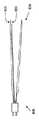
図2は、導電性要素210に付着したとき電気付着組織マニプレータ200によって持ち上げられる膜220を示す。図2は、持ち上げられた膜を強調表示するための照明プローブ220を示す。 FIG. 2 shows a
電気付着を確立するために、第1のパルス310(図3参照)のパルス継続時間は、約10マイクロ秒と約10ミリ秒との間で変化し得る。より具体的には、第1のパルスの継続時間は、約1マイクロ秒と約0.5ミリ秒との間であり得る。パルスの継続時間の上限は熱拡散によって規制される。即ち100μmを超える熱損傷を回避するために、パルス継続時間は好ましくは10ミリ秒を超えないようにすべきである。パルスエネルギーは、導電性要素の周囲での完全な蒸気キャビティの形成のために必要な閾値エネルギーより低いエネルギーであるべきである。完全な蒸気キャビティは、組織から導電性要素を分離させて、付着を防止する。実際、蒸気キャビティの効果を利用して、導電性要素から付着した組織を分離させている(後述)。 To establish electroadhesion, the pulse duration of the first pulse 310 (see FIG. 3) can vary between about 10 microseconds and about 10 milliseconds. More specifically, the duration of the first pulse can be between about 1 microsecond and about 0.5 milliseconds. The upper limit of the pulse duration is regulated by thermal diffusion. That is, in order to avoid thermal damage exceeding 100 μm, the pulse duration should preferably not exceed 10 milliseconds. The pulse energy should be lower than the threshold energy required for the formation of a complete vapor cavity around the conductive element. A complete vapor cavity separates the conductive element from the tissue and prevents adhesion. In fact, the effect of the vapor cavity is used to separate the attached tissue from the conductive element (described later).
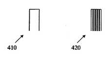
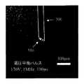
第1のパルスは、1個のパルス410か複数パルスのバースト420であり得、約0.1kHzと10MHzの間の周波数であり得る。第1のパルスは、単極性、電荷平衡若しくは電圧平衡両極性パルスバーストであり得る。プローブを組織層に接触されつつそのようなパルスまたは2、3のパルス群を供給すると、組織の金属表面への付着が生じ、従って組織を持ち上げて操作可能となる。或る実施形態では、パルスパラメータは、200Vでパルス継続時間が100マイクロ秒である。電圧は50V以上500V未満とすべきである。プラズマ形成の閾値が、パルスパラメート及び電極の形状に応じて変わるが概ね200〜400Vの間にあるからである。エレクトロポレーションによって生ずる組織損傷を最小限にするために、電圧平衡パルス列を印加することも可能である。最適な設定での損傷は、図5に示すようにプローブ520に隣接する1層か2層の細胞の層を超えない程度である。 The first pulse can be a
導電性要素から組織層を取り外すために、(エネルギーが)より強い第2のパルス320を印加して、そのパルスがプローブの周囲に完全な蒸気キャビティを形成させ、もって組織が導電性要素から外れるようにする必要がある。その第2のパルスも、1個のパルス410か複数パルスのバースト420であり得、約0.1kHzと10MHzとの間の周波数であり得る。第2のパルスの継続時間は、約10マイクロ秒と約10ミリ秒の間であり得る。より具体的には、第2のパルスの継続時間は、約1マイクロ秒と約0.5ミリ秒との間であり得る。第2のパルスも、単極性、電荷平衡若しくは電圧平衡両極性パルスバーストであり得る。エレクトロポレーションによって生ずる組織損傷を最小限にするために、電圧平衡パルス列を印加することも可能である。 To remove the tissue layer from the conductive element, a second (energy) stronger
導電性要素の組織層への付着をうまく行うために、導電性要素の表面を、生物学的な汚染物質が付着していない状態に維持しておくことが重要である。導電性要素が汚染即ち凝固したタンパク質や他の材料の層で覆われてしまった場合は、導電性要素は、手術野から引き出すことなく容易にクリーニングすることができる。このクリーニングは、例えば、プラズマ媒介切除処置のなかでごく僅かのパルスを印加することによって行うことができる。これらのパルスによって導電性要素から全ての汚染物質が除去される。この処理の間の組織の損傷を避けるために、導電性要素は、組織から一定の距離だけ引き出しておくべきである。或る実施形態では、導電性要素を0.1mm以上引き出した。この距離は、切除処置における一般的な損傷領域の幅より大きい長さである。 In order for the conductive element to adhere successfully to the tissue layer, it is important to keep the surface of the conductive element free of biological contaminants. If the conductive element has been covered with a layer of contaminated or coagulated protein or other material, the conductive element can be easily cleaned without being pulled out of the surgical field. This cleaning can be done, for example, by applying very few pulses during the plasma-mediated ablation procedure. These pulses remove all contaminants from the conductive element. In order to avoid tissue damage during this process, the conductive element should be pulled a certain distance from the tissue. In some embodiments, the conductive element was drawn 0.1 mm or more. This distance is greater than the width of a typical damaged area in an ablation procedure.
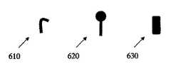
本発明を幾つかの実施例によって説明してきたが、この実施例は、本発明の全側面の例示の趣旨で記載したものであり、本発明を限定するものではない。従って、本発明は、当業者が本明細書の記載から導き出すことができる、詳細な実施形態における種々の改変を包含し得る。例えば、導電性要素は種々の形状を取り得るが、鋭さのない形状が好ましい。図6は、フック形状610、ボール形状620、または矩形630等の種々の形状を有する導電性要素の例を示す。これらの例は全て、本発明の範囲を限定する趣旨ではなく単なる例示の趣旨で示すものである。 While the invention has been described in terms of several embodiments, the embodiments are described for the purpose of illustrating all aspects of the invention and are not intended to limit the invention. Accordingly, the present invention may encompass various modifications in detailed embodiments that can be derived from the description herein by a person skilled in the art. For example, the conductive element can take a variety of shapes, but a shape with no sharpness is preferred. FIG. 6 shows examples of conductive elements having various shapes such as
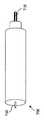
従来の医療器具も、それを絶縁性材料で被覆した上で活性電極として使用される部分を露出することによって、本発明で実現される電気付着式組織操作の特徴を組み合わせることができる。図7は、組織の分離を良好にするべく、持ち上げた組織層の下に液体、薬剤、薬物を注射するための針710を組み合わせた電気付着組織マニプレータ700を示す。針の全表面は露出されて活性導電性要素(電極)として使用されるか、或いはその表面の一部が被覆され、かつ一部が露出される。図8は、絶縁性材料によって被覆され得る従来型のピンセット800を示す。アームのストリップ(例えば、位置810または820)は露出して導電性要素(電極)として使用することができ、これによって本発明の特徴を実現する電気ピンセットを開発できる。機械的な力を高めるため、ピンセットの第2の(従来型の)アームを、組織が株組織から剥がされた直後にその組織を機械的に把持するために用いてもよい。ピンセット800の第2のアーム830を、活性導電性要素(電極)として作ることもできる。この組合せは、例えば第1にアームに付着した組織を切断するために利用することができる。組織が一方の側のみからアクセスされるため、本発明の特徴を実現する装置は、従来型のマイクロピンセットが通常そうであるように先の尖った末端を有している必要はない。尖った先端部がないことで、このピンセットは、偶然、意図せずに組織に突き刺さってしまうようなことに関して安全なものとなる。 Conventional medical devices can also be combined with the features of electroadhesive tissue manipulation realized in the present invention by exposing the portion used as the active electrode after coating it with an insulating material. FIG. 7 shows an
ここで説明した種類の用途に加えて、電気付着組織マニプレータは、例えば硝子体網膜の手術において、薄い膜を剥いだり持ち上げたりするために用いることができる。電気付着組織マニプレータの他の用途は、眼球後極手術のための眼球表面にレンズホルダを取り付けるための用途(電流縫合術の代わりとしての用途)である。この用途では、レンズホルダは、その周辺に活性電極または活性電極のアレイを有しているべきであり、この活性電極が、(角膜表面への損傷の可能性を避けるための)角膜外部での強膜への付着を生ずる。本発明の更に別の用途として、組織に移植片を固定するために付着したり、手術中に組織表面に一時的なパッチを付着すること等が挙げられる。更に別の用途として、組織を骨格に付着したり、或いは導電性ステントを用いて切断した血管の2つの端部を再結合すること等が挙げられる。 In addition to the types of applications described herein, electroadhesive tissue manipulators can be used to peel and lift thin films, for example, in vitreal retina surgery. Another application of the electroadhesive tissue manipulator is for attaching a lens holder to the eyeball surface for retrobulbar surgery (application as an alternative to current suturing). In this application, the lens holder should have an active electrode or array of active electrodes around it, which is outside the cornea (to avoid possible damage to the corneal surface). Adhesion to the sclera occurs. Still other uses of the present invention include attaching to a tissue to secure a graft, or attaching a temporary patch to a tissue surface during surgery. Yet another application includes attaching tissue to the skeleton or rejoining the two ends of a blood vessel that has been cut using a conductive stent.
上記した種々の改変の全ては、特許請求の範囲に記載の本発明の範囲及び精神の範囲に包含されるものと考えられる。 All of the various modifications described above are considered to be within the scope and spirit of the present invention as set forth in the appended claims.
Claims (17)
Translated fromJapanese(a)導電性要素と、
(b)前記導電性要素に、第1のパルスと第2のパルスを供給できる電気的手段であって、前記第1のパルスは前記導電性要素と組織層との間に、前記組織層を操作するに十分な強度の付着状態を形成し、前記第2のパルスは、前記導電性要素から付着した前記組織層を取り外すための前記組織層に対する非付着状態を形成する、該電気的要素と、
(c)前記第1のパルスと前記第2のパルスの発生を制御する制御手段とを有することを特徴とする電気付着組織マニプレータ。An electroadhesive tissue manipulator comprising:
(A) a conductive element;
(B) electrical means capable of supplying a first pulse and a second pulse to the conductive element, the first pulse interposing the tissue layer between the conductive element and the tissue layer; An electrical element that forms an attachment state that is strong enough to manipulate, and wherein the second pulse forms a non-attachment state to the tissue layer for removing the tissue layer attached from the conductive element; ,
(C) An electroadhesive tissue manipulator comprising control means for controlling the generation of the first pulse and the second pulse.
(a)導電性要素を準備する過程と、
(b)前記導電性要素に第1のパルスを供給する過程であって、前記第1のパルスが前記導電性要素と組織層との間に付着状態を作り出す、該過程と、
(c)付着した前記組織層を操作する過程とを含むことを特徴とする方法。A method of manipulating an organization,
(A) preparing a conductive element;
(B) supplying a first pulse to the conductive element, wherein the first pulse creates an attachment between the conductive element and a tissue layer;
(C) manipulating the attached tissue layer.
(a)導電性要素と、
(b)前記導電性要素に、第1のパルスと第2のパルスを供給できる電気的手段であって、前記第1のパルスは前記導電性要素と組織層との間に、前記医療器具を用いて前記組織層を操作するに十分な強度の付着状態を形成し、前記第2のパルスは、前記導電性要素から付着した前記組織層を取り外すための前記組織層に対する非付着状態を形成する、該電気的要素と、
(c)前記第1のパルスと前記第2のパルスの発生を制御する制御手段とを有することを特徴とする医療器具。A medical device,
(A) a conductive element;
(B) electrical means capable of supplying a first pulse and a second pulse to the conductive element, the first pulse interposing the medical device between the conductive element and the tissue layer; The second pulse forms an unattached state to the tissue layer for removing the attached tissue layer from the conductive element. The electrical element;
(C) A medical instrument comprising control means for controlling the generation of the first pulse and the second pulse.
Applications Claiming Priority (2)
| Application Number | Priority Date | Filing Date | Title |
|---|---|---|---|
| US47982503P | 2003-06-18 | 2003-06-18 | |
| PCT/US2004/019785WO2004112581A2 (en) | 2003-06-18 | 2004-06-18 | Electro-adhesive tissue manipulator |
Publications (1)
| Publication Number | Publication Date |
|---|---|
| JP2007526012Atrue JP2007526012A (en) | 2007-09-13 |
Family
ID=33539226
Family Applications (1)
| Application Number | Title | Priority Date | Filing Date |
|---|---|---|---|
| JP2006517483APendingJP2007526012A (en) | 2003-06-18 | 2004-06-18 | Electroadhesive tissue manipulator |
Country Status (8)
| Country | Link |
|---|---|
| US (2) | US20050021028A1 (en) |
| EP (1) | EP1648280A4 (en) |
| JP (1) | JP2007526012A (en) |
| AU (1) | AU2004249284A1 (en) |
| CA (1) | CA2529512A1 (en) |
| MX (1) | MXPA05013761A (en) |
| NZ (1) | NZ544092A (en) |
| WO (1) | WO2004112581A2 (en) |
Cited By (1)
| Publication number | Priority date | Publication date | Assignee | Title |
|---|---|---|---|---|
| JP2022525344A (en)* | 2019-03-15 | 2022-05-12 | ボストン サイエンティフィック サイムド,インコーポレイテッド | Spatial multiplexed waveform for selective cell resection |
Families Citing this family (21)
| Publication number | Priority date | Publication date | Assignee | Title |
|---|---|---|---|---|
| US8043286B2 (en) | 2002-05-03 | 2011-10-25 | The Board Of Trustees Of The Leland Stanford Junior University | Method and apparatus for plasma-mediated thermo-electrical ablation |
| US6780178B2 (en)* | 2002-05-03 | 2004-08-24 | The Board Of Trustees Of The Leland Stanford Junior University | Method and apparatus for plasma-mediated thermo-electrical ablation |
| US7736361B2 (en)* | 2003-02-14 | 2010-06-15 | The Board Of Trustees Of The Leland Stamford Junior University | Electrosurgical system with uniformly enhanced electric field and minimal collateral damage |
| EP1648280A4 (en)* | 2003-06-18 | 2007-08-15 | Univ Leland Stanford Junior | ELECTRO-ADHESIVE TISSUE MANIPULATOR |
| JP5032500B2 (en)* | 2006-01-03 | 2012-09-26 | アルコン,インコーポレイティド | System for dissociation and removal of proteinaceous tissue |
| AU2007245098A1 (en)* | 2006-03-31 | 2007-11-08 | Peak Surgical, Inc. | Devices and methods for tissue welding |
| JP2010508899A (en) | 2006-11-02 | 2010-03-25 | ピーク サージカル, インコーポレイテッド | Tissue cutting and coagulation with electrical plasma, and surgical devices |
| US20090306642A1 (en)* | 2008-06-10 | 2009-12-10 | Vankov Alexander B | Method for low temperature electrosugery and rf generator |
| US8137345B2 (en) | 2009-01-05 | 2012-03-20 | Peak Surgical, Inc. | Electrosurgical devices for tonsillectomy and adenoidectomy |
| US8515510B2 (en)* | 2009-03-31 | 2013-08-20 | Covidien Lp | Electroadhesive medical devices |
| US20110118729A1 (en)* | 2009-11-13 | 2011-05-19 | Alcon Research, Ltd | High-intensity pulsed electric field vitrectomy apparatus with load detection |
| US20110118734A1 (en)* | 2009-11-16 | 2011-05-19 | Alcon Research, Ltd. | Capsularhexis device using pulsed electric fields |
| US20110135626A1 (en)* | 2009-12-08 | 2011-06-09 | Alcon Research, Ltd. | Localized Chemical Lysis of Ocular Tissue |
| US20110144562A1 (en)* | 2009-12-14 | 2011-06-16 | Alcon Research, Ltd. | Localized Pharmacological Treatment of Ocular Tissue Using High-Intensity Pulsed Electrical Fields |
| WO2011081897A1 (en)* | 2009-12-15 | 2011-07-07 | Alcon Research, Ltd. | High-intensity pulsed electric field vitrectomy apparatus |
| US8546979B2 (en) | 2010-08-11 | 2013-10-01 | Alcon Research, Ltd. | Self-matching pulse generator with adjustable pulse width and pulse frequency |
| WO2012170364A1 (en) | 2011-06-10 | 2012-12-13 | Medtronic, Inc. | Wire electrode devices for tonsillectomy and adenoidectomy |
| KR20160039922A (en)* | 2014-10-02 | 2016-04-12 | 삼성전자주식회사 | Image processing apparatus and control method thereof |
| EP3181080A1 (en)* | 2015-12-15 | 2017-06-21 | Netvlieschirurg B.V. | Microsurgical fine gripping and diathermy forceps and scissors |
| KR102006907B1 (en)* | 2018-03-12 | 2019-10-01 | 주식회사 씨오아이 | Surgicalunit for ophthalmology |
| US12280492B2 (en) | 2020-08-31 | 2025-04-22 | The Board Of Trustees Of The University Of Illinois | Electrothermal manipulator |
Citations (3)
| Publication number | Priority date | Publication date | Assignee | Title |
|---|---|---|---|---|
| JP2001503657A (en)* | 1996-11-08 | 2001-03-21 | ハウザー,ラッセル,エイ. | Transcutaneous bypass graft and fixation system |
| JP2001178740A (en)* | 1999-12-24 | 2001-07-03 | Olympus Optical Co Ltd | Endoscopic treatment device |
| US20020052599A1 (en)* | 2000-10-31 | 2002-05-02 | Gyrus Medical Limited | Electrosurgical system |
Family Cites Families (99)
| Publication number | Priority date | Publication date | Assignee | Title |
|---|---|---|---|---|
| US3903891A (en)* | 1968-01-12 | 1975-09-09 | Hogle Kearns Int | Method and apparatus for generating plasma |
| US3799168A (en)* | 1972-02-28 | 1974-03-26 | R Peters | Electro-surgical handle |
| US3987795A (en)* | 1974-08-28 | 1976-10-26 | Valleylab, Inc. | Electrosurgical devices having sesquipolar electrode structures incorporated therein |
| US4043342A (en)* | 1974-08-28 | 1977-08-23 | Valleylab, Inc. | Electrosurgical devices having sesquipolar electrode structures incorporated therein |
| US4161950A (en)* | 1975-08-01 | 1979-07-24 | The United States Of America As Represented By The United States Department Of Energy | Electrosurgical knife |
| US4034762A (en)* | 1975-08-04 | 1977-07-12 | Electro Medical Systems, Inc. | Vas cautery apparatus |
| US4074718A (en)* | 1976-03-17 | 1978-02-21 | Valleylab, Inc. | Electrosurgical instrument |
| US4202337A (en)* | 1977-06-14 | 1980-05-13 | Concept, Inc. | Bipolar electrosurgical knife |
| US4228800A (en)* | 1978-04-04 | 1980-10-21 | Concept, Inc. | Bipolar electrosurgical knife |
| US4248231A (en)* | 1978-11-16 | 1981-02-03 | Corning Glass Works | Surgical cutting instrument |
| US4476862A (en)* | 1980-12-08 | 1984-10-16 | Pao David S C | Method of scleral marking |
| US4805616A (en)* | 1980-12-08 | 1989-02-21 | Pao David S C | Bipolar probes for ophthalmic surgery and methods of performing anterior capsulotomy |
| US4674499A (en)* | 1980-12-08 | 1987-06-23 | Pao David S C | Coaxial bipolar probe |
| US4429694A (en)* | 1981-07-06 | 1984-02-07 | C. R. Bard, Inc. | Electrosurgical generator |
| US4492231A (en)* | 1982-09-17 | 1985-01-08 | Auth David C | Non-sticking electrocautery system and forceps |
| US4534347A (en)* | 1983-04-08 | 1985-08-13 | Research Corporation | Microwave coagulating scalpel |
| US4590934A (en)* | 1983-05-18 | 1986-05-27 | Jerry L. Malis | Bipolar cutter/coagulator |
| US4593691A (en)* | 1983-07-13 | 1986-06-10 | Concept, Inc. | Electrosurgery electrode |
| US4597388A (en)* | 1983-12-15 | 1986-07-01 | Trutek Research, Inc. | Apparatus for removing cataracts |
| US4589411A (en)* | 1985-02-08 | 1986-05-20 | Aaron Friedman | Electrosurgical spark-gap cutting blade |
| US4655215A (en)* | 1985-03-15 | 1987-04-07 | Harold Pike | Hand control for electrosurgical electrodes |
| US4936301A (en)* | 1987-06-23 | 1990-06-26 | Concept, Inc. | Electrosurgical method using an electrically conductive fluid |
| US4943290A (en)* | 1987-06-23 | 1990-07-24 | Concept Inc. | Electrolyte purging electrode tip |
| DE8709363U1 (en)* | 1987-07-07 | 1988-11-03 | Siemens AG, 1000 Berlin und 8000 München | Shock wave source |
| DE3815835A1 (en)* | 1988-05-09 | 1989-11-23 | Flachenecker Gerhard | HIGH FREQUENCY GENERATOR FOR TISSUE CUTTING AND COAGULATION IN HIGH FREQUENCY SURGERY |
| US4927420A (en)* | 1988-11-14 | 1990-05-22 | Colorado Biomedical, Inc. | Ultra-sharp tungsten needle for electrosurgical knife |
| JP2697039B2 (en)* | 1988-12-06 | 1998-01-14 | 住友化学工業株式会社 | Method for producing positive resist composition |
| AU4945490A (en)* | 1989-01-06 | 1990-08-01 | Angioplasty Systems Inc. | Electrosurgical catheter for resolving atherosclerotic plaque |
| US4938761A (en)* | 1989-03-06 | 1990-07-03 | Mdt Corporation | Bipolar electrosurgical forceps |
| US5080660A (en)* | 1990-05-11 | 1992-01-14 | Applied Urology, Inc. | Electrosurgical electrode |
| US5217547A (en)* | 1991-05-17 | 1993-06-08 | Furukawa Aluminum Co., Ltd. | Aluminum alloy fin material for heat exchanger |
| US5330471A (en)* | 1991-06-07 | 1994-07-19 | Hemostatic Surgery Corporation | Bi-polar electrosurgical endoscopic instruments and methods of use |
| US5348553A (en)* | 1991-12-18 | 1994-09-20 | Whitney Douglass G | Method for promoting blood vessel healing |
| US5891095A (en)* | 1993-05-10 | 1999-04-06 | Arthrocare Corporation | Electrosurgical treatment of tissue in electrically conductive fluid |
| US6183469B1 (en)* | 1997-08-27 | 2001-02-06 | Arthrocare Corporation | Electrosurgical systems and methods for the removal of pacemaker leads |
| US6355032B1 (en)* | 1995-06-07 | 2002-03-12 | Arthrocare Corporation | Systems and methods for selective electrosurgical treatment of body structures |
| US6770071B2 (en)* | 1995-06-07 | 2004-08-03 | Arthrocare Corporation | Bladed electrosurgical probe |
| US5697882A (en)* | 1992-01-07 | 1997-12-16 | Arthrocare Corporation | System and method for electrosurgical cutting and ablation |
| US5683366A (en)* | 1992-01-07 | 1997-11-04 | Arthrocare Corporation | System and method for electrosurgical tissue canalization |
| US6102046A (en)* | 1995-11-22 | 2000-08-15 | Arthrocare Corporation | Systems and methods for electrosurgical tissue revascularization |
| US5281216A (en)* | 1992-03-31 | 1994-01-25 | Valleylab, Inc. | Electrosurgical bipolar treating apparatus |
| US5300068A (en)* | 1992-04-21 | 1994-04-05 | St. Jude Medical, Inc. | Electrosurgical apparatus |
| US5293863A (en)* | 1992-05-08 | 1994-03-15 | Loma Linda University Medical Center | Bladed endoscopic retractor |
| US5254121A (en)* | 1992-05-22 | 1993-10-19 | Meditron Devices, Inc. | Method and device for removing concretions within human ducts |
| US5318563A (en)* | 1992-06-04 | 1994-06-07 | Valley Forge Scientific Corporation | Bipolar RF generator |
| US5417687A (en)* | 1993-04-30 | 1995-05-23 | Medical Scientific, Inc. | Bipolar electrosurgical trocar |
| US6254600B1 (en)* | 1993-05-10 | 2001-07-03 | Arthrocare Corporation | Systems for tissue ablation and aspiration |
| US6832996B2 (en)* | 1995-06-07 | 2004-12-21 | Arthrocare Corporation | Electrosurgical systems and methods for treating tissue |
| US5599346A (en)* | 1993-11-08 | 1997-02-04 | Zomed International, Inc. | RF treatment system |
| US5458596A (en)* | 1994-05-06 | 1995-10-17 | Dorsal Orthopedic Corporation | Method and apparatus for controlled contraction of soft tissue |
| US5549604A (en)* | 1994-12-06 | 1996-08-27 | Conmed Corporation | Non-Stick electroconductive amorphous silica coating |
| US6447511B1 (en)* | 1994-12-13 | 2002-09-10 | Symbiosis Corporation | Bipolar endoscopic surgical scissor blades and instrument incorporating the same |
| US5897553A (en)* | 1995-11-02 | 1999-04-27 | Medtronic, Inc. | Ball point fluid-assisted electrocautery device |
| US5669904A (en)* | 1995-03-07 | 1997-09-23 | Valleylab Inc. | Surgical gas plasma ignition apparatus and method |
| US5647871A (en)* | 1995-03-10 | 1997-07-15 | Microsurge, Inc. | Electrosurgery with cooled electrodes |
| US6837887B2 (en)* | 1995-06-07 | 2005-01-04 | Arthrocare Corporation | Articulated electrosurgical probe and methods |
| US6293942B1 (en)* | 1995-06-23 | 2001-09-25 | Gyrus Medical Limited | Electrosurgical generator method |
| EP1025807B1 (en)* | 1995-06-23 | 2004-12-08 | Gyrus Medical Limited | An electrosurgical instrument |
| US6023638A (en)* | 1995-07-28 | 2000-02-08 | Scimed Life Systems, Inc. | System and method for conducting electrophysiological testing using high-voltage energy pulses to stun tissue |
| US6267757B1 (en)* | 1995-08-09 | 2001-07-31 | Eclipse Surgical Technologies, Inc. | Revascularization with RF ablation |
| EP0871405B1 (en)* | 1995-11-20 | 2001-02-14 | Storz Endoskop GmbH | Bipolar high-frequency surgical instrument |
| US6228082B1 (en)* | 1995-11-22 | 2001-05-08 | Arthrocare Corporation | Systems and methods for electrosurgical treatment of vascular disorders |
| US6126656A (en)* | 1996-01-30 | 2000-10-03 | Utah Medical Products, Inc. | Electrosurgical cutting device |
| CN1216929A (en)* | 1996-02-02 | 1999-05-19 | 血管转换公司 | Method and apparatus for blocking flow through blood vessels |
| US6458121B1 (en)* | 1996-03-19 | 2002-10-01 | Diapulse Corporation Of America | Apparatus for athermapeutic medical treatments |
| US6113594A (en)* | 1996-07-02 | 2000-09-05 | Ethicon, Inc. | Systems, methods and apparatus for performing resection/ablation in a conductive medium |
| US5785704A (en)* | 1996-07-29 | 1998-07-28 | Mrc Systems Gmbh | Method for performing stereotactic laser surgery |
| US6352535B1 (en)* | 1997-09-25 | 2002-03-05 | Nanoptics, Inc. | Method and a device for electro microsurgery in a physiological liquid environment |
| US5891142A (en)* | 1996-12-06 | 1999-04-06 | Eggers & Associates, Inc. | Electrosurgical forceps |
| US6059783A (en)* | 1997-06-26 | 2000-05-09 | Kirwan Surgical Products, Inc. | Electro-surgical forceps which minimize or prevent sticking of tissue |
| US6039735A (en)* | 1997-10-03 | 2000-03-21 | Megadyne Medical Products, Inc. | Electric field concentrated electrosurgical electrode |
| US6287305B1 (en)* | 1997-12-23 | 2001-09-11 | Team Medical, L.L.C. | Electrosurgical instrument |
| US5958266A (en)* | 1997-10-24 | 1999-09-28 | Fugo; Richard J. | Method of plasma incision of matter with a specifically tuned radiofrequency electromagnetic field generator |
| US6533781B2 (en)* | 1997-12-23 | 2003-03-18 | Team Medical Llc | Electrosurgical instrument |
| US6210404B1 (en)* | 1998-10-28 | 2001-04-03 | John H. Shadduck | Microjoule electrical discharge catheter for thrombolysis in stroke patients |
| US6047700A (en)* | 1998-03-30 | 2000-04-11 | Arthrocare Corporation | Systems and methods for electrosurgical removal of calcified deposits |
| US6287306B1 (en)* | 1998-06-22 | 2001-09-11 | Daig Corporation | Even temperature linear lesion ablation catheter |
| US6787730B2 (en)* | 1998-07-09 | 2004-09-07 | Damian Coccio | Device for plasma incision of matter with a specifically tuned radiofrequency electromagnetic field generator |
| US6132427A (en)* | 1998-09-21 | 2000-10-17 | Medicor Corporation | Electrosurgical instruments |
| US6398779B1 (en)* | 1998-10-23 | 2002-06-04 | Sherwood Services Ag | Vessel sealing system |
| US6174309B1 (en)* | 1999-02-11 | 2001-01-16 | Medical Scientific, Inc. | Seal & cut electrosurgical instrument |
| US6210408B1 (en)* | 1999-02-24 | 2001-04-03 | Scimed Life Systems, Inc. | Guide wire system for RF recanalization of vascular blockages |
| US6135998A (en)* | 1999-03-16 | 2000-10-24 | Board Of Trustees Of The Leland Stanford Junior University | Method and apparatus for pulsed plasma-mediated electrosurgery in liquid media |
| US6228084B1 (en)* | 1999-04-06 | 2001-05-08 | Kirwan Surgical Products, Inc. | Electro-surgical forceps having recessed irrigation channel |
| DE19919072C2 (en)* | 1999-04-27 | 2001-12-13 | Wolf Gmbh Richard | Bipolar forceps |
| US6723091B2 (en)* | 2000-02-22 | 2004-04-20 | Gyrus Medical Limited | Tissue resurfacing |
| US6500176B1 (en)* | 2000-10-23 | 2002-12-31 | Csaba Truckai | Electrosurgical systems and techniques for sealing tissue |
| EP1437977B1 (en)* | 2001-10-02 | 2014-05-21 | ArthroCare Corporation | Apparatus for electrosurgical removal and digestion of tissue |
| US8043286B2 (en)* | 2002-05-03 | 2011-10-25 | The Board Of Trustees Of The Leland Stanford Junior University | Method and apparatus for plasma-mediated thermo-electrical ablation |
| US6780178B2 (en)* | 2002-05-03 | 2004-08-24 | The Board Of Trustees Of The Leland Stanford Junior University | Method and apparatus for plasma-mediated thermo-electrical ablation |
| EP1569570B1 (en)* | 2002-11-27 | 2006-11-15 | Medical Device Innovations Limited | Tissue ablation apparatus |
| AU2003297459A1 (en)* | 2002-12-20 | 2004-07-22 | Manoa Medical, Inc. | Systems and methods for cutting tissue |
| US7195627B2 (en)* | 2003-01-09 | 2007-03-27 | Gyrus Medical Limited | Electrosurgical generator |
| US7736361B2 (en)* | 2003-02-14 | 2010-06-15 | The Board Of Trustees Of The Leland Stamford Junior University | Electrosurgical system with uniformly enhanced electric field and minimal collateral damage |
| EP1603474B1 (en)* | 2003-02-14 | 2013-09-11 | The Board Of Trustees Of The Leland Stanford Junior University | Electrosurgical system with uniformly enhanced electric field and minimal collateral damage |
| EP1648280A4 (en)* | 2003-06-18 | 2007-08-15 | Univ Leland Stanford Junior | ELECTRO-ADHESIVE TISSUE MANIPULATOR |
| US7195630B2 (en)* | 2003-08-21 | 2007-03-27 | Ethicon, Inc. | Converting cutting and coagulating electrosurgical device and method |
| US7182762B2 (en)* | 2003-12-30 | 2007-02-27 | Smith & Nephew, Inc. | Electrosurgical device |
| DE102005013714A1 (en)* | 2004-04-07 | 2005-12-22 | Carl Zeiss Meditec Ag | Electrical probe for microsurgery |
- 2004
- 2004-06-18EPEP04755740Apatent/EP1648280A4/ennot_activeWithdrawn
- 2004-06-18NZNZ544092Apatent/NZ544092A/enunknown
- 2004-06-18WOPCT/US2004/019785patent/WO2004112581A2/enactiveApplication Filing
- 2004-06-18CACA002529512Apatent/CA2529512A1/ennot_activeAbandoned
- 2004-06-18MXMXPA05013761Apatent/MXPA05013761A/enunknown
- 2004-06-18AUAU2004249284Apatent/AU2004249284A1/ennot_activeAbandoned
- 2004-06-18JPJP2006517483Apatent/JP2007526012A/enactivePending
- 2004-06-18USUS10/871,697patent/US20050021028A1/ennot_activeAbandoned
- 2007
- 2007-10-12USUS11/974,611patent/US20080119842A1/ennot_activeAbandoned
Patent Citations (3)
| Publication number | Priority date | Publication date | Assignee | Title |
|---|---|---|---|---|
| JP2001503657A (en)* | 1996-11-08 | 2001-03-21 | ハウザー,ラッセル,エイ. | Transcutaneous bypass graft and fixation system |
| JP2001178740A (en)* | 1999-12-24 | 2001-07-03 | Olympus Optical Co Ltd | Endoscopic treatment device |
| US20020052599A1 (en)* | 2000-10-31 | 2002-05-02 | Gyrus Medical Limited | Electrosurgical system |
Cited By (2)
| Publication number | Priority date | Publication date | Assignee | Title |
|---|---|---|---|---|
| JP2022525344A (en)* | 2019-03-15 | 2022-05-12 | ボストン サイエンティフィック サイムド,インコーポレイテッド | Spatial multiplexed waveform for selective cell resection |
| JP7402889B2 (en) | 2019-03-15 | 2023-12-21 | ボストン サイエンティフィック サイムド,インコーポレイテッド | Spatial multiplexed waveforms for selective cell ablation |
Also Published As
| Publication number | Publication date |
|---|---|
| US20050021028A1 (en) | 2005-01-27 |
| CA2529512A1 (en) | 2004-12-29 |
| AU2004249284A1 (en) | 2004-12-29 |
| WO2004112581A3 (en) | 2006-03-23 |
| US20080119842A1 (en) | 2008-05-22 |
| WO2004112581A2 (en) | 2004-12-29 |
| EP1648280A2 (en) | 2006-04-26 |
| MXPA05013761A (en) | 2006-03-08 |
| NZ544092A (en) | 2008-08-29 |
| EP1648280A4 (en) | 2007-08-15 |
Similar Documents
| Publication | Publication Date | Title |
|---|---|---|
| JP2007526012A (en) | Electroadhesive tissue manipulator | |
| JP6697777B2 (en) | Capsulotomy device | |
| EP0651974B1 (en) | Bipolar electrosurgical instrument and method for making the instrument | |
| JP6482560B2 (en) | Electrosurgical end effector | |
| JP5404605B2 (en) | Electrosurgical system with uniformly enhanced electric field and minimal collateral damage | |
| US20070179512A1 (en) | Surgical support structure | |
| US11166844B2 (en) | Retinal patch graft and biopsy device | |
| CA2051392A1 (en) | Focal destruction of eye tissue by electroablation | |
| CN108882958A (en) | The grasping of microsurgery precision and diathermy clamp and diathermy cutter device for intraocular surgery | |
| JP4255582B2 (en) | Corneal incision device | |
| US20200078214A1 (en) | Systems and methods for pulsed posterior vitreous detachment creation | |
| US20200155348A1 (en) | Capsulorhexis apparatus | |
| KR20080014804A (en) | Epithelial Bag Expansion Tool and Combination of Epithelial Dissociator and Corneal Correction | |
| WO2007121281A2 (en) | System for conditioning surfaces in vivo | |
| WO1992019167A1 (en) | Eye surgery performed with an electrosurgical instrument | |
| KR20120138396A (en) | Double-edged eyelid operation apparatus | |
| JP2020093021A (en) | Bipolar electric tweezers | |
| JP2009273559A (en) | Hemostatic device | |
| UA139161U (en) | ELECTROSURGICAL MICROINSTRUMENT FOR BIPOLAR HIGH FREQUENCY WELDING OF THE FRONT AND DEEP DEPARTMENTS OF THE MUCOSAL MALONAL COVER | |
| JP2000107194A (en) | Bipolar tweezers | |
| JP2011056184A (en) | Defibrillation electrode |
Legal Events
| Date | Code | Title | Description |
|---|---|---|---|
| A131 | Notification of reasons for refusal | Free format text:JAPANESE INTERMEDIATE CODE: A131 Effective date:20091201 | |
| A601 | Written request for extension of time | Free format text:JAPANESE INTERMEDIATE CODE: A601 Effective date:20100301 | |
| A602 | Written permission of extension of time | Free format text:JAPANESE INTERMEDIATE CODE: A602 Effective date:20100308 | |
| A02 | Decision of refusal | Free format text:JAPANESE INTERMEDIATE CODE: A02 Effective date:20100601 |