JP2007525285A - System and method for operating a laparoscopic surgical instrument - Google Patents
System and method for operating a laparoscopic surgical instrumentDownload PDFInfo
- Publication number
- JP2007525285A JP2007525285AJP2007500887AJP2007500887AJP2007525285AJP 2007525285 AJP2007525285 AJP 2007525285AJP 2007500887 AJP2007500887 AJP 2007500887AJP 2007500887 AJP2007500887 AJP 2007500887AJP 2007525285 AJP2007525285 AJP 2007525285A
- Authority
- JP
- Japan
- Prior art keywords
- tip
- surgical instrument
- pin
- slot
- working rod
- Prior art date
- Legal status (The legal status is an assumption and is not a legal conclusion. Google has not performed a legal analysis and makes no representation as to the accuracy of the status listed.)
- Pending
Links
- 238000000034methodMethods0.000titleabstractdescription13
- 230000033001locomotionEffects0.000claimsabstractdescription26
- 230000007246mechanismEffects0.000claimsdescription17
- 230000005540biological transmissionEffects0.000claimsdescription11
- 238000007667floatingMethods0.000claimsdescription11
- 239000002184metalSubstances0.000claimsdescription6
- 238000003466weldingMethods0.000claimsdescription5
- 238000003754machiningMethods0.000claimsdescription4
- 238000005266castingMethods0.000claimsdescription3
- 238000001746injection mouldingMethods0.000claimsdescription3
- 238000004080punchingMethods0.000claimsdescription3
- 230000000694effectsEffects0.000abstractdescription2
- 238000013461designMethods0.000description9
- 239000000463materialSubstances0.000description6
- 230000008569processEffects0.000description5
- 238000003860storageMethods0.000description3
- 238000013459approachMethods0.000description2
- 230000008878couplingEffects0.000description2
- 238000010168coupling processMethods0.000description2
- 238000005859coupling reactionMethods0.000description2
- 238000010438heat treatmentMethods0.000description2
- 238000004519manufacturing processMethods0.000description2
- 238000007493shaping processMethods0.000description2
- 230000001133accelerationEffects0.000description1
- 239000000853adhesiveSubstances0.000description1
- 230000001070adhesive effectEffects0.000description1
- 230000008859changeEffects0.000description1
- 238000002347injectionMethods0.000description1
- 239000007924injectionSubstances0.000description1
- 230000013011matingEffects0.000description1
- 238000012986modificationMethods0.000description1
- 230000004048modificationEffects0.000description1
- 238000012805post-processingMethods0.000description1
- 238000004663powder metallurgyMethods0.000description1
- 230000000717retained effectEffects0.000description1
- 239000007787solidSubstances0.000description1
- 238000012546transferMethods0.000description1
- XLYOFNOQVPJJNP-UHFFFAOYSA-NwaterSubstancesOXLYOFNOQVPJJNP-UHFFFAOYSA-N0.000description1
Images


Classifications
- A—HUMAN NECESSITIES
- A61—MEDICAL OR VETERINARY SCIENCE; HYGIENE
- A61B—DIAGNOSIS; SURGERY; IDENTIFICATION
- A61B17/00—Surgical instruments, devices or methods
- A61B17/32—Surgical cutting instruments
- A61B17/3201—Scissors
- A—HUMAN NECESSITIES
- A61—MEDICAL OR VETERINARY SCIENCE; HYGIENE
- A61B—DIAGNOSIS; SURGERY; IDENTIFICATION
- A61B17/00—Surgical instruments, devices or methods
- A61B17/16—Instruments for performing osteoclasis; Drills or chisels for bones; Trepans
- A61B17/1604—Chisels; Rongeurs; Punches; Stamps
- A61B17/1606—Chisels; Rongeurs; Punches; Stamps of forceps type, i.e. having two jaw elements moving relative to each other
- A61B17/1608—Chisels; Rongeurs; Punches; Stamps of forceps type, i.e. having two jaw elements moving relative to each other the two jaw elements being linked to two elongated shaft elements moving longitudinally relative to each other
- A—HUMAN NECESSITIES
- A61—MEDICAL OR VETERINARY SCIENCE; HYGIENE
- A61B—DIAGNOSIS; SURGERY; IDENTIFICATION
- A61B17/00—Surgical instruments, devices or methods
- A61B17/28—Surgical forceps
- A61B17/29—Forceps for use in minimally invasive surgery
- A—HUMAN NECESSITIES
- A61—MEDICAL OR VETERINARY SCIENCE; HYGIENE
- A61B—DIAGNOSIS; SURGERY; IDENTIFICATION
- A61B17/00—Surgical instruments, devices or methods
- A61B17/32—Surgical cutting instruments
- A—HUMAN NECESSITIES
- A61—MEDICAL OR VETERINARY SCIENCE; HYGIENE
- A61B—DIAGNOSIS; SURGERY; IDENTIFICATION
- A61B17/00—Surgical instruments, devices or methods
- A61B17/32—Surgical cutting instruments
- A61B17/320016—Endoscopic cutting instruments, e.g. arthroscopes, resectoscopes
- A—HUMAN NECESSITIES
- A61—MEDICAL OR VETERINARY SCIENCE; HYGIENE
- A61B—DIAGNOSIS; SURGERY; IDENTIFICATION
- A61B17/00—Surgical instruments, devices or methods
- A61B17/28—Surgical forceps
- A61B17/29—Forceps for use in minimally invasive surgery
- A61B2017/2926—Details of heads or jaws
- A61B2017/2932—Transmission of forces to jaw members
- A61B2017/2933—Transmission of forces to jaw members camming or guiding means
- A61B2017/2934—Transmission of forces to jaw members camming or guiding means arcuate shaped guiding means
- A—HUMAN NECESSITIES
- A61—MEDICAL OR VETERINARY SCIENCE; HYGIENE
- A61B—DIAGNOSIS; SURGERY; IDENTIFICATION
- A61B17/00—Surgical instruments, devices or methods
- A61B17/28—Surgical forceps
- A61B17/29—Forceps for use in minimally invasive surgery
- A61B2017/2926—Details of heads or jaws
- A61B2017/2932—Transmission of forces to jaw members
- A61B2017/2933—Transmission of forces to jaw members camming or guiding means
- A61B2017/2936—Pins in guiding slots
Landscapes
- Health & Medical Sciences (AREA)
- Surgery (AREA)
- Life Sciences & Earth Sciences (AREA)
- Medical Informatics (AREA)
- Animal Behavior & Ethology (AREA)
- Engineering & Computer Science (AREA)
- Biomedical Technology (AREA)
- Heart & Thoracic Surgery (AREA)
- Veterinary Medicine (AREA)
- Molecular Biology (AREA)
- Nuclear Medicine, Radiotherapy & Molecular Imaging (AREA)
- General Health & Medical Sciences (AREA)
- Public Health (AREA)
- Orthopedic Medicine & Surgery (AREA)
- Pathology (AREA)
- Dentistry (AREA)
- Oral & Maxillofacial Surgery (AREA)
- Ophthalmology & Optometry (AREA)
- Surgical Instruments (AREA)
Abstract
Translated fromJapaneseDescription
Translated fromJapanese 本件は、2004年2月27日出願の「腹腔鏡外科手術器具を作動させるシステムおよびその方法(System and Method of Actuating a Laparoscopic Surgical Instrument)」という名称の仮出願連続番号60/548,747号の優先権を主張する非仮出願であり、該仮出願の全体は本件で引例にあげることにより本明細書の一部に組み込まれるものとする。 This is the priority of the provisional
本発明は、広義には、腹腔鏡外科手術器具に関するものであり、特に、腹腔鏡外科手術器具の先端部を作動させるシステムおよびその方法に関連している。 The present invention relates generally to laparoscopic surgical instruments and, more particularly, to a system and method for operating the tip of a laparoscopic surgical instrument.
作業刃または作業先端部を使う腹腔鏡外科手術器具または同様の装置は、通例、何らかの機械手段で作動状態にされる。大半の場合、外科手術器具または外科手術装置を作業ロッドとして使って、装置の一方端に在るハンドルからの運動を反対端の先端部に伝達している。腹腔鏡鋏と腹腔鏡把持装置に共通して、作業ロッドは先端部の孔と関連して作動するピンを備えている。作業ロッドを移動させることでスロット内でピンにカム伝達機能を実施させ、これにより先端部が開閉する。 Laparoscopic surgical instruments or similar devices that use a working blade or working tip are typically activated by some mechanical means. In most cases, a surgical instrument or surgical device is used as a working rod to transmit motion from a handle at one end of the device to the tip at the opposite end. In common with laparoscopic scissors and laparoscopic gripping devices, the working rod includes a pin that operates in conjunction with a hole in the tip. By moving the working rod, the pin performs a cam transmission function in the slot, and thereby the tip is opened and closed.
刃または先端部は、通例、旋回点より近位にスロットが設けられており、このような配置のゆえに、刃または先端部の裏面端部を非常に大きくする必要がある。把持装置に取付けて使用される場合で、かつ、先端部がそれぞれに開位置にある場合は、先端部の裏面端部が把持装置シャフトの外径を越えて外に張り出し、「翼」のように見える。これは、使用中に先端部が体組織または他の装置を捕獲してしまった場合、或いは、干渉する場合があると、使用者にとっては問題となる場合があり、特に、患者にとっては問題である。 The blade or tip is usually provided with a slot proximal to the pivot point, and because of this arrangement, the back end of the blade or tip needs to be very large. When used by attaching to the gripping device and the tip is in the open position, the back end of the tip protrudes beyond the outer diameter of the gripping device shaft and looks like a wing. Looks like. This can be a problem for the user, especially if the tip has captured body tissue or other devices during use or may interfere with it, especially for patients. is there.
鋏に取付けて使用される場合、上述のような翼は可塑材の収縮性管材で完全に被覆され、電気外科焼灼術中は全ての金属構成要素を電気絶縁するように図ることが極めて多い。しかしながら、鋏または先端部が開いている場合、翼が伸張して、収縮管材を変形させることがある。これは、鋏が套管針から引き出された場合に、変形した管材が弛緩しない場合があるため、管材がカニューレの端部を捕獲してしまい、患者から套管針を引き出す恐れがあるという点で問題がある。従って、当該技術分野では、腹腔鏡の刃または先端部を作動させて翼の望ましくない効果を最小限に抑えた改良型システムおよび改良法が必要である。 When used attached to a scissors, the wing as described above is completely covered with a plastic shrinkable tubing and very often attempts to electrically insulate all metal components during electrosurgical cauterization. However, if the heel or tip is open, the wings may stretch and deform the shrink tubing. This is because when the scissors are pulled out of the trocar, the deformed tubing may not relax, and the tubing may capture the end of the cannula and may withdraw the trocar from the patient. There is a problem. Accordingly, there is a need in the art for improved systems and methods that actuate the laparoscopic blade or tip to minimize the undesirable effects of the wing.
本発明はピンとスロットの設計を目的としており、本発明の一局面では、刃または先端部から作業ロッドへと駆動スロットを移動させる。その結果、刃または先端部は各々の裏面端部の面積を非常に低減することができ、刃または先端部は、十分に偏向している間でも、外側管材または外側シャフトの外径を越えて張り出すのはほんの僅かな部分であるか、または、皆無である。これにより、把持装置の使用中は刃または先端部を捕獲するものが皆無となることが確実になるばかりか、鋏に被せられた収縮管材は決して変形しないことも確実になる。これを実現することができる理由は、スロットのための領域が必要ないせいである。更に、作業ロッドの刃または先端部に設けられた駆動スロットの利用可能面積が外側管材または外側シャフトの全体径まで最大限にされるが、このことで、刃または先端部は更にてこの力を得ることができる。更に、スロットの深さは可変であり、作動時に刃または先端部により強い引張り力を付与することができる。 The present invention is directed to pin and slot design, and in one aspect of the present invention, the drive slot is moved from the blade or tip to the working rod. As a result, the blade or tip can greatly reduce the area of each back end, and the blade or tip can exceed the outer diameter of the outer tube or outer shaft, even while fully deflected. There are only a few or no overhangs. This not only ensures that there is nothing to capture the blade or tip during use of the gripping device, but also ensures that the shrink tubing over the heel is never deformed. The reason that this can be achieved is that no area for the slot is needed. Furthermore, the available area of the drive slot provided on the blade or tip of the working rod is maximized to the overall diameter of the outer tube or shaft, which further increases the force of the blade or tip. Obtainable. Further, the depth of the slot is variable, and a strong tensile force can be applied to the blade or the tip during operation.
より詳細に述べると、本発明は外科手術器具を目的としており、該器具は軸線沿いに延びる細長い管材と、第1ピンを有する第1先端部と、第2ピンを有する第2先端部とを備えており、細長い管材の内側には作業ロッドが同軸に滑動自在に設けられており、第1ピンは第1先端部の近位端表面に形成されており、第2ピンは第2先端部の近位端表面に形成されており、第2先端部は細長い管材に作動自在に接続された共通旋回ピンで第1先端部に旋回自在に接続されて、作業ロッドの運動に応じて先端部を開閉するようになっている。この局面について、作業ロッドには第1先端部のピンおよび第2先端部のピンを受容するスロットが設けられており、スロットにはスロット内でピンが滑動するカム運動伝達面が設けられており、先端部の近位端は先端部の作動中に細長い管材の直径より外側への張り出しが最小限になるように拡張する。また別な局面では、2つの先端部の近位端は先端部それぞれの作動中に細長い管材の直径より外側へ張り出すことが無い。作業ロッドは、機械加工、打ち抜き加工、重ね成形加工、鋳造加工、または、金属の射出成形加工などによって形成される。ピンは、圧力嵌め、ネジ嵌め、溶接、接着などにより、先端部の近位端面に形成される。作業ロッドはトング型作業ロッドやフォーク型作業ロッドでもよい。フォーク型作業ロッドについては、ロッドはその両側に貫通スロットが設けられており、これらは湾曲していて互いに交軸関係にあってもよい。トング型作業ロッドには、また、2本の湾曲した交軸スロットがトング状部の両側に設けられていてもよい。これらスロットは開放端スロットでも閉鎖端スロットでもよいことが分かる。上述のように、スロットは、その長尺部に沿って深さが変動するようになっていてもよい。特に、スロットの深さを変えることにより、先端部に沿って加える引張り力を変動させることができる。また別な局面では、トング型作業ロッドには、先端部を所望位置に徐々に移動させるラチェット手段が設けられていてもよく、ラチェット手段は一連の戻り止めが設けられている。 More particularly, the present invention is directed to a surgical instrument that includes an elongate tube extending along an axis, a first tip having a first pin, and a second tip having a second pin. The working rod is coaxially slidably provided inside the elongated tube material, the first pin is formed on the proximal end surface of the first tip portion, and the second pin is the second tip portion. The second tip is pivotally connected to the first tip with a common pivot pin operably connected to the elongated tube, and the tip is adapted to the movement of the working rod. Open and close. In this aspect, the working rod is provided with a slot for receiving the first tip pin and the second tip pin, and the slot is provided with a cam motion transmission surface on which the pin slides. The proximal end of the tip expands to minimize overhanging of the elongated tube diameter during actuation of the tip. In another aspect, the proximal ends of the two tips do not protrude beyond the diameter of the elongated tube during operation of each of the tips. The working rod is formed by machining, punching, overmolding, casting, or metal injection molding. The pin is formed on the proximal end surface of the tip portion by pressure fitting, screw fitting, welding, adhesion, or the like. The working rod may be a tong type working rod or a fork type working rod. For fork-type working rods, the rods are provided with through slots on both sides thereof, which may be curved and in an axial relationship. The tong-type working rod may also be provided with two curved intersecting axis slots on both sides of the tong-shaped part. It can be seen that these slots may be open end slots or closed end slots. As described above, the depth of the slot may vary along its long portion. In particular, the tensile force applied along the tip can be varied by changing the depth of the slot. In another aspect, the tong-type work rod may be provided with ratchet means for gradually moving the tip portion to a desired position, and the ratchet means is provided with a series of detents.
本発明のまた別な局面では、外科手術器具が開示されており、該器具は、軸線沿いに延びる細長い管材と、第1カムスロットを有する第1先端部と、第2カムスロットを有する第2先端部とを備えており、細長い管材の内側には作業ロッドが同軸に作動自在に設けられており、第1カムスロットには第1カム運動伝達面が設けられており、第2カムスロットには第2カム運動伝達面が設けられており、第2先端部は細長い管材に作動自在に接続された共通旋回ピンで第1先端部に旋回自在に接続されて、作業ロッドの運動に応じて先端部を開閉するようになっている。この局面について、作業ロッドには浮動駆動ピンを保持する第3スロットが設けられており、浮動駆動ピンは第1カムスロットと第2カムスロットを通して設置されており、2つの先端部の近位端は先端部それぞれの作動中に細長い管材の直径より外側への張り出しが最小限になるように拡張する。また別な局面では、先端部の近位端は先端部の作動中に細長い管材の直径より外側へ張り出すことが無い。第3スロットは垂直方向スロットであってもよく、また、細長い管材はその近位部に浮動駆動ピンを更に備えていてもよい。 In yet another aspect of the invention, a surgical instrument is disclosed that includes an elongated tube extending along an axis, a first tip having a first cam slot, and a second having a second cam slot. A working rod is coaxially operable inside the elongated tube, a first cam slot is provided with a first cam motion transmission surface, and a second cam slot is provided in the second cam slot. Is provided with a second cam motion transmission surface, and the second tip portion is pivotally connected to the first tip portion by a common pivot pin operably connected to the elongated tube material, and according to the movement of the work rod. The tip is opened and closed. For this aspect, the working rod is provided with a third slot for holding a floating drive pin, the floating drive pin being installed through the first cam slot and the second cam slot, the proximal ends of the two tips. Expands so that overhanging of the elongated tube diameter is minimized during operation of each tip. In yet another aspect, the proximal end of the tip does not protrude outward from the diameter of the elongated tube during operation of the tip. The third slot may be a vertical slot and the elongate tube may further comprise a floating drive pin at its proximal portion.
本発明のまた別な局面では、外科手術器具が開示されており、該器具は、軸線沿いに延びるとともに回転自在な外側シャフトおよび同軸内側ロッドが設けられたシャフト組立体と、第1ピンを有する第1先端部と、第2ピンを有する第2先端部とを備えており、第1ピンは第1先端部の近位端面に形成されており、第2ピンは第2先端部の近位端面に形成されており、第2先端部はシャフト組立体に作動自在に接続された共通旋回ピンで第1先端部に旋回自在に接続されて、外側シャフトの運動に応じて先端部を開閉するようになっている。この局面について、外側シャフトには第1先端部のピンと第2先端部のピンを受容するスロットが設けられており、スロットにはその中でピンが滑動するカム運動伝達面が設けられており、2つの先端部の近位端は先端部それぞれの作動中にシャフト組立体の直径より外側への張り出しが最小限になるように拡張し、先端部は外側シャフトを回転させることによって作動される。また別な局面では、2つの先端部の近位端は先端部それぞれの作動中にシャフト組立体の直径より外側へ張り出すことが無い。 In yet another aspect of the present invention, a surgical instrument is disclosed that includes a shaft assembly extending along an axis and provided with a rotatable outer shaft and a coaxial inner rod, and a first pin. A first tip portion and a second tip portion having a second pin are provided, the first pin is formed on the proximal end surface of the first tip portion, and the second pin is proximal to the second tip portion. The second tip is formed on the end face, and the second tip is pivotally connected to the first tip by a common pivot pin operably connected to the shaft assembly, and opens and closes according to the movement of the outer shaft. It is like that. For this aspect, the outer shaft is provided with a slot for receiving the first tip pin and the second tip pin, and the slot is provided with a cam motion transmission surface in which the pin slides, The proximal ends of the two tips expand to minimize overhanging the diameter of the shaft assembly during operation of each of the tips, and the tips are actuated by rotating the outer shaft. In another aspect, the proximal ends of the two tips do not protrude beyond the diameter of the shaft assembly during operation of each of the tips.
本発明の上記特徴および利点とそれ以外の特徴および利点は、添付の図面を参照しながら実施形態を説明すれば明らかになる。 The above and other features and advantages of the present invention will become apparent from the following description of the embodiments with reference to the accompanying drawings.
図1を参照すると、米国特許第5,626,609号に例示されているような先行技術の腹腔鏡外科手術器具100の斜視図があり、該特許は引例に挙げることにより本明細書の一部をなすものとする。外科手術器具100は、通例、固定ハンドル12と旋回ハンドル14とを有するハンドル組立体10を備えている。ハンドル組立体10からシャフト組立体20が延びているが、該シャフト組立体は外側管材22と内側作業ロッド24を有している。作業ロッド24は外側管材20を同軸関係で滑動させる。外側管材22は固定ハンドル12に固着され、一方、作業ロッド24は旋回ハンドル14に固着される。シャフト組立体20の遠位端には器具メカニズム30が取り付けられているが、該器具メカニズムは下位顎部材32と上位顎部材34からなる。器具メカニズム30は連結メカニズム40を介して旋回点36でシャフト組立体20に接続されている。使用中は、作業ロッド24が外側管材22の内側を滑動すると、連結メカニズム40は旋回点36を中心として顎部材32、34を旋回させるように作動し、両顎部材を開閉させる。 Referring to FIG. 1, there is a perspective view of a prior art laparoscopic
図2および図3を参照すると、先行技術の器具メカニズム30aが例示されているが、これは、例えば、第1の鋏刃32aと第2の鋏刃34aを備えている。この実施形態では、収納部材50は外側管材22に取り付けられており、器具メカニズム30aは収納部材50に取り付けられている。ハンドルが移動すると、作業ロッド24は外側管材22を通って器具メカニズム30aに向けて滑動する。図2に例示されているように、鋏刃32a、34aにはカムスロット38、39がそれぞれに設けられており、これらスロットが内側ロッド24に取り付けられたベアリングポスト60を受容する。ロッド24が移動すると、ベアリングポスト60がカムスロット38、39の内部を滑動して旋回点36aを中心として刃32a、34aを旋回させ、刃を開閉させることになる。この器具メカニズム30aの欠点は、刃32a、34aが開くと、両刃の後端が収納部材50のスロットを通り抜けて、両刃とも開かせてしまうことである。すなわち、刃32a、34aの後端は外科手術器具の外径を越えて外に張り出して、「翼」のように見える。これは、使用中に両刃の後端が体組織またはそれ以外の装置を捕獲したり、或いは、干渉するようなことになった場合には、使用者にとっては問題となる。更に、刃32a、34aが開いている時は、翼が伸張して、シャフト組立体20を電気絶縁するために使用されていた可塑性収縮管材を変形させてしまうことがある。例えば、処置後に器具が套管針から引き出されると、変形された管材は弛緩せず、カニューレの端部を捕獲し、患者の体外に套管針を引き出してしまう恐れがある。 With reference to FIGS. 2 and 3, a prior
図4Aから図4Cを参照すると、本発明の第1の局面による外科手術装置200に器具メカニズム210が設けられているのが例示されており、該器具メカニズムは第1の刃または第2先端部212と第2の刃または第2先端部214を有しており、これら先端部は各々にピン218とピン216がそれぞれの近位端に形成されている。ピン218、216は、通例は、溶接により刃または先端部212、214に固着されており、刃または先端部212、214の裏面端部の主面から外方向に延びている。刃または先端部212、214は重ね合わされて鋏の形状になり、共通ピン220によって外側管材と旋回関係に保持されている。本発明の新規な特徴は、以下でより詳しく説明しているように、スロットを設けた作業ロッド224と相互作用する器具メカニズム210を備えている点である。刃または先端部212、214はスロットではなくピン218、216が設けられているため、裏面端部に大きな面積を必要としないことが分かる。これが有利なのは、刃または先端部212、214の「翼幅」は、翼が開いている時に最小になるからであるが、但し、翼幅が排除されていない場合に限る。更に、刃または先端部212、214とロッド224の総強度は最大になるが、これは、ロッドと両刃の双方が一体であるから、すなわち、単体構成部材であるからである。 Referring to FIGS. 4A-4C, a
フォーク型作業ロッド224は多数の異なる方法で形成される。例えば、所望の機能部は、所望の径の中実ロッドまたは管材から機械加工される。また別な局面では、金属片が端部に所望のスロットを設けるように打ち抜き加工されてから管材を特定の径に巻き上げ、スロットを設けた端部が「二股フォーク部」を形成する。また別な局面では、作業ロッドの端部のフォーク機能部をシャフト上に重ね成形して、経費効率のよい構成部材をもたらすことができる。 The fork-
トング型作業ロッドについては、フォーク型作業ロッドと同様の方法で形成される。より詳しく述べると、先端部の細部を機械加工することは、細部を重ね成形するのと同様に、任意である。作業ロッドの端部は別個の部分として形成され、すなわち、成形し、機械加工し、鋳造し、金属射出成形加工し、或いは、それ以外の方法で加工することで、その部分の機能部の細部を設けることができるが、その後に、ネジ嵌め、スナップ嵌め、粘着剤、溶接プロセス、または、それ以外に何らかの取付け方法で標準シャフトに装着される。 The tongue type working rod is formed by the same method as the fork type working rod. More specifically, machining the details of the tip is optional as well as overmolding the details. The end of the working rod is formed as a separate part, i.e. molded, machined, cast, metal injection molded or otherwise machined, so that the functional details of that part are But can then be attached to a standard shaft by screw fit, snap fit, adhesive, welding process, or some other attachment method.
図5を参照すると、図4の器具メカニズム210が作業ロッド224に接続されているのを例示した斜視図がある。刃または先端部212、214を製造する多数の方法が存在することが分かる。例えば、刃または先端部212、214を従来の打ち抜き加工で形成してから、熱処理に付す。また別な実施例では、刃または先端部212、214は予備硬化された材料の半加工品から形成されてから、放電加工切断され、水噴射切断され、レーザー切断され、または、機械加工されて、最終形状を得ることができる。刃または先端部212、214の裏側端部のピン218、216は刃またはピンそれら自体の上に直接形成されてもよいし、或いは、ピンが製造された後で付加されてもよいことに留意するべきである。 Referring to FIG. 5, there is a perspective view illustrating the
ピン218、216は次の複数の方法のうちの1つ、または、組み合わせによりロックすることができる。すなわち、圧力嵌め、スエージ嵌め、ネジ嵌め、および/または、溶接である。刃または先端部212、214の一部としてピンを製造するために、多数のプロセスを利用することができる。シート状の材料を機械加工して、旋回穴のほかにピンも設けることができる。このシート材料は加熱処理を受けてから研削整形装置に送られ、この装置が刃または先端部の輪郭を研削して造ることができる。研削整形後のプレートは放電加工切断され、第2の輪郭が切り出される。この種のプロセスは、駆動ピンを一体配置した多数の構成部材を、比較的廉価で生産することを可能にする。
最小数の作業から完全な部材を生産することのできる別なプロセスがある。その具体例として、金属射出成形(MIM)し、鋳造し、粉末冶金する(PM)というプロセスがあるが、これらに限定されない。最終的な刃は研磨され、或いは、それ以外の後処理に付される。 There are other processes that can produce complete parts from a minimum number of operations. Specific examples thereof include, but are not limited to, processes of metal injection molding (MIM), casting, and powder metallurgy (PM). The final blade is polished or otherwise subjected to post processing.
以下に、本発明のピンとスロットの設計について述べていくが、この場合、実現可能な利点が多数ある。例えば、
(1)刃または先端部は各々の裏側端部の面積が減じられて、刃または先端部が、十分に偏向されている間でも、外側管材または外側シャフトの外径を越えて外へ張り出すのは極めて僅かな部分だけであるか、または、皆無である。これにより、把持装置の使用中に刃または先端部を捕獲するものは全く無くなり、鋏に被せられている収縮管材が変形されることが決してないことを確実にする。こうなるのは、スロットのための領域が必要とされなくなるせいである。
(2)作業ロッドの刃または先端部に設けられる駆動スロットの利用可能面積は、外側管材または外側シャフトの全体径まで最大限にされるが、これにより、刃または先端部に付加的なてこ力が加わる。
(3)作業ロッドにチャネルが設けられている場合は、チャネルの深さは変動させて、作動時に刃に加えられる引張り力を徐々に増大させることができる。
更に、刃または先端部から作業ロッドまでスロットを移動させることにより、刃の「翼幅」は低減または排除することができるが、これは、裏側端部がスロットを設ける必要はなく、むしろ、小型ピンを設けることで、体組織、他の器具、または、縫合糸を捕獲する可能性を最小限に抑えている。In the following, the pin and slot design of the present invention will be described. For example,
(1) The area of the back end of each blade or tip is reduced, and the blade or tip extends beyond the outer diameter of the outer tube or outer shaft even while the blade or tip is sufficiently deflected. There are very few or none. This ensures that there is no capture of the blade or tip during use of the gripping device, ensuring that the shrink tubing covered by the heel is never deformed. This is because the area for the slot is no longer needed.
(2) The available area of the drive slot provided on the blade or tip of the working rod is maximized up to the overall diameter of the outer tube or outer shaft, which allows additional leverage on the blade or tip. Will be added.
(3) When the working rod is provided with a channel, the depth of the channel can be varied to gradually increase the tensile force applied to the blade during operation.
Furthermore, by moving the slot from the blade or tip to the working rod, the “blade width” of the blade can be reduced or eliminated, but this does not require the back end to be slotted, rather it is compact. Providing pins minimizes the possibility of capturing body tissue, other instruments, or sutures.
図6Aおよび図6Bを参照すると、作業ロッドの端部が例示されているが、作業炉度はフォーク型の設計224aまたはトング型設計224bのいずれであってもよい。フォーク型設計224aを採用した場合は、貫通スロット226はロッド224aの両側に形成される。刃または先端部の裏側端部はロッドに挿入することができるが、その場合、第1の刃または第1先端部のピンは第1スロットにロックされ、第2の刃または第2先端部のピンは対向する第2スロットにロックされる。刃または先端部は、外側管材または外側シャフトに設けられた共通旋回点によって固定することができる。作業ロッドが一方向に移動されると、刃または先端部はピンとスロット226を介して回転運動を受けることになる。刃または先端部の各々をシャフトにロックしているピンは刃または先端部と一体であってもよいし、或いは、別個の構成要素であってもよい。フォーク型設計224aと同様に、トング設計224bは、更に後段で論じるように、トング状部の両側にスロット226が設けられている。 Referring to FIGS. 6A and 6B, the end of the working rod is illustrated, but the working furnace can be either fork-type design 224a or tong-type design 224b. When the fork design 224a is employed, the through
図7Aおよび図7Bを参照すると、作業ロッド224がトング状端部の両側にスロット226を組み入れているのを例示した斜視図と側面図がある。上述のように、刃または先端部は、裏側端部に、ロッドのスロットに収まるピンが設けられる。ロッドは前方に押され、或いは、後方に引張られて、刃または先端部に回転運動を伝達し、刃または先端部は外側管材または外側シャフトに取り付けられた共通旋回点によって旋回させられる。場合によっては、複数の互いに異なる長さの先端部について、力を変動させながら、先端部をそれぞれ異なる開口部へと複数の異なる速度で移動させる複数の異なるスロット設計を設定するのが有利となる場合がある。図7Cおよび図7Dを参照すると、スロット226は、所望に応じて、開端部スロットまたは閉端部スロット(もしくは、その両方の組み合わせ)を含む。図7Eおよび図7Fは、本発明の別な局面により、作業ロッドに湾曲したスロットが設けられたのを例示している。本発明の両刃または両先端部を設けている顎の旋回点を刃と刃の合流点とする場合、ピンおよびスロットと蝶番との間の距離は作業ロッドの位置次第で変動することが分かる。従って、本発明の湾曲したスロットを使ってこの現象を補正し、作業ロッドと顎運動との間の関係をより直線形に近づけることができる。例えば、刃または先端部が閉位置に近づくと、スロットはより制御し易い形状になり、刃または先端部が開位置に近づくと、加速度が高まる形状になる。この局面について、器具は調整により、所望の器具制御と使用者へのフィードバックを供与することができる。 Referring to FIGS. 7A and 7B, there are a perspective view and a side view illustrating that the working
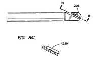
本発明の別な実施形態では、図8Aおよび図8Bに例示されているように、トング状部のスロット226bはスロットに角度を設けるような形状にすることができる。換言すると、一方端B'におけるスロット226bの深度は他方端A'228における深度よりも深いか、浅いか、いずれであってもよい。これが有利であるのは、作業ロッド224が引張られて、刃または先端部が閉じると、スロットの底面の角度により、スロット内でカム伝達動作をしているピンが強制的に引き離される。これにより、両刃または両先端部のそれぞれの裏面端部が散会し、これが今度は、両刃または両先端部のそれぞれの表面が一緒になって切断面沿いにより強い引張り力を付与することになる。 In another embodiment of the present invention, as illustrated in FIGS. 8A and 8B, the tongue slot 226b may be shaped to provide an angle to the slot. In other words, the depth of the slot 226b at one end B ′ may be deeper or shallower than the depth at the other end A′228. This is advantageous because when the working
図8Cに例示されているような本発明のまた別な局面では、スロット226に戻り止めまたは斜角転換部229が設けられて、ハンドル動作に対して両顎部の線形運動に影響を与えずに、刃または先端部を所望位置へ暫定的に「ロックする」または「ラチェット式に徐々に移動させる」のが図示されている。図8Dは、スロット226dにまた、複数の異なる断面部が設けられているのを例示しており、例えば、スロット226dには、鳩の尾状の輪郭230を有するロックメカニズムが設けられている。この実施形態について、刃または先端部に設けられた嵌合ピンはスロットと一致して、その中に「ロックする」。 In yet another aspect of the present invention, as illustrated in FIG. 8C, a detent or
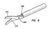
図9に例示されているような本発明の別な局面では、両刃または両先端部212、214ともに可動である必要はない。すなわち、一方の刃212は固定されるが、他方の刃214が作動できるようになっていればよい。可動刃214は、ピン300と、刃214を作動させるのにスロットが1個しか設けられていない作業ロッド302とを備えているようにしてもよい。 In another aspect of the present invention as illustrated in FIG. 9, both blades or
本発明のまた別な局面では、図10Aおよび図10Bは、作業ロッド410に浮動駆動ピン402を設けた外科手術器具400を例示している。より詳しく述べると、作業ロッド410には垂直方向スロット404が設けられており、駆動ピン402が中を浮遊できるようにしている。この局面については、駆動ピン402は刃または先端部412のスロット406、刃または先端部414のスロット408をそれぞれに通して設置され、作業ロッドスロットに配置される。外側シャフト先端部416は先端部から内側へ延びる浮動ピンスロット418を有している。浮動駆動ピン402はこのスロット内を滑動し、該スロット内に保有される。旋回ピン420はシャフトの先端部に配置されて、先端部組立体を適所にロックする。 In yet another aspect of the invention, FIGS. 10A and 10B illustrate a
図11を参照すると、本発明のまた別な局面が例示されているが、ここでは、スロットまたはチャネル226は上述の設計のいずれであってもよいが、作業ロッドは複数の多元的部材片224c、224dに分岐されて、刃または先端部に独立した運動を供与する。これは、両刃または両先端部がそれぞれに異なる速度で合流する必要がある場合、または、それぞれに異なる距離を移動して合流する必要がある場合には、有用となる。 Referring to FIG. 11, yet another aspect of the present invention is illustrated, where the slot or
図12を参照すると、本発明のまた別な局面が例示されており、この場合、スロットまたはチャネルは作業ロッドに配置せずに、むしろ、外側シャフト524に配置されている。特に、両刃または両先端部512、514は、刃512のピン516を例外として、前述の設計のものに類似しており、具体的には、ピンが外側シャフト524まで延びており、該外側シャフトにスロット518が設けられているため、刃または先端部512、514のそれぞれのピン516、520を受容するようになっている。本発明のこの局面について、両刃または両先端部512、514は外側シャフト524を回転させることにより作動されるが、これにより、ピン516、520は外側シャフト524のスロット518に沿って運動をカム伝達し、刃512、514を開閉させる。外側シャフト524は多数部材片から構成されていてもよく、また、貫通スロットではなく、むしろ、チャネルを備えているようにしてもよい。 Referring to FIG. 12, yet another aspect of the present invention is illustrated, where the slot or channel is not located on the working rod, but rather is located on the
本発明の精神および範囲から逸脱せずに、多種多様に開示された実施形態について、上記以外に多数の修正を行うことができることが分かる。このため、上記説明は本発明を制限するものと解釈するべきではなく、好ましい実施形態の単なる具体例と理解されるべきである。 It will be appreciated that many other modifications may be made to the various disclosed embodiments without departing from the spirit and scope of the invention. Therefore, the above description should not be construed as limiting the invention, but merely as examples of preferred embodiments.
Claims (30)
Translated fromJapanese軸線沿いに延びる細長い管材を備えており、細長い管材の内側には作業ロッドが管材と同軸に滑動自在に設けられており、
第1ピンを有する第1先端部を更に備えており、第1ピンは第1先端部の近位端表面に形成されており、
第2ピンを有する第2先端部を更に備えており、第2ピンは第2先端部の近位端表面に形成されており、第2先端部は細長い管材に作動自在に接続された共通旋回ピンで第1先端部に旋回自在に接続されて、作業ロッドの運動に応じて先端部を開閉するようになっており、
作業ロッドには第1先端部のピンおよび第2先端部のピンを受容するスロットが設けられており、スロットにはスロット内でピンが滑動するカム運動伝達面が設けられており、両先端部のそれぞれの近位端は、先端部の作動中に細長い管材の直径より外側への張り出しが最小限になるように拡張する、外科手術器具。A surgical instrument,
It has an elongated tube extending along the axis, and a working rod is slidably provided coaxially with the tube inside the elongated tube.
A first tip having a first pin, the first pin being formed on a proximal end surface of the first tip;
A common swivel further comprising a second tip having a second pin, the second pin being formed on a proximal end surface of the second tip, the second tip being operatively connected to an elongated tube. A pin is pivotally connected to the first tip, and the tip is opened and closed according to the movement of the work rod.
The working rod is provided with a slot for receiving the pin at the first tip and the pin at the second tip, and the slot is provided with a cam motion transmission surface for sliding the pin in the slot. Surgical instrument wherein the proximal end of each expands so that overhanging of the elongated tube diameter is minimized during actuation of the tip.
軸線沿いに延びる細長い管材を備えており、細長い管材の内側には作業ロッドが管材と同軸に作動自在に設けられており、
第1カム運動伝達面が設けられた第1カムスロットを有する第1先端部と、
第2カム運動伝達面が設けられた第2カムスロットを有する第2先端部とを更に備えており、第2先端部は細長い管材に作動自在に接続された共通旋回ピンで第1先端部に旋回自在に接続されて、作業ロッドの運動に応じて先端部を開閉するようになっており、
作業ロッドには浮動駆動ピンを保持する第3スロットが設けられており、浮動駆動ピンは第1カムスロットと第2カムスロットを通して設置されており、前記両先端部のそれぞれの近位端は、先端部の作動中に細長い管材の直径より外側への張り出しが最小限になるように拡張する、外科手術器具。A surgical instrument,
It has an elongated tube extending along the axis, and a working rod is provided on the inside of the elongated tube so as to be operable coaxially with the tube.
A first tip having a first cam slot provided with a first cam motion transmission surface;
And a second tip portion having a second cam slot provided with a second cam motion transmission surface, and the second tip portion is a common pivot pin operably connected to the elongated tube member and is connected to the first tip portion. It is connected so that it can rotate freely, and it opens and closes the tip according to the movement of the work rod.
The working rod is provided with a third slot for holding a floating drive pin. The floating drive pin is installed through the first cam slot and the second cam slot, and the proximal ends of the two end portions are respectively A surgical instrument that expands during operation of the tip to minimize overhanging of the elongated tube diameter.
軸線沿いに延びるとともに、回転自在な外側シャフトおよび同軸内側ロッドが設けられたシャフト組立体と、
第1ピンを有する第1先端部とを備えており、第1ピンは第1先端部の近位端面に形成されており、
第2ピンを有する第2先端部を更に備えており、第2ピンは第2先端部の近位端面に形成されており、第2先端部はシャフト組立体に作動自在に接続された共通旋回ピンで第1先端部に旋回自在に接続されて、外側シャフトの運動に応じて先端部を開閉するようになっており、
外側シャフトには第1先端部のピンと第2先端部のピンを受容する第スロットが設けられており、第スロットにはその中でピンが滑動するカム運動伝達面が設けられており、両先端部のそれぞれの近位端は、先端部それぞれの作動中にシャフト組立体の直径より外側への張り出しが最小限になるように拡張する、外科手術器具。A surgical instrument,
A shaft assembly extending along an axis and provided with a rotatable outer shaft and a coaxial inner rod;
A first tip having a first pin, the first pin being formed on the proximal end surface of the first tip,
A common swivel further comprising a second tip having a second pin, the second pin being formed on a proximal end surface of the second tip, the second tip being operatively connected to the shaft assembly. A pin is pivotally connected to the first tip, and the tip is opened and closed according to the movement of the outer shaft,
The outer shaft is provided with a first slot for receiving the pin at the first tip and the pin at the second tip, and the second slot is provided with a cam motion transmission surface in which the pin slides. A surgical instrument wherein each proximal end of the section expands to minimize overhanging of the diameter of the shaft assembly during operation of each of the tips.
軸線沿いに延びる細長い管材を備えており、細長い管材の内側には作業ロッドが管材と同軸に滑動自在に設けられており、
ピンを有する第1先端部を更に備えており、ピンは第1先端部の近位端表面に形成されており、
共通の旋回ピンで第1先端部に旋回自在に接続されているとともに、細長い管材に作動自在に接続されて作業ロッドの運動に応じて第1先端部を開閉するようにした第2先端部を更に備えており、
作業ロッドにはピンを受容するスロットが設けられており、スロットにはスロット内でピンが滑動するカム運動伝達面が設けられており、第1先端部の近位端は、先端部の作動中に細長い管材の直径より外側への張り出しが最小限になるように拡張する、外科手術器具。A surgical instrument,
It has an elongated tube extending along the axis, and a working rod is slidably provided coaxially with the tube inside the elongated tube.
A first tip having a pin, the pin formed on a proximal end surface of the first tip;
A second tip portion that is pivotally connected to the first tip portion with a common pivot pin and is operably connected to an elongated tube member so as to open and close the first tip portion according to the movement of the work rod. In addition,
The working rod is provided with a slot for receiving the pin, the slot is provided with a cam motion transmission surface in which the pin slides, and the proximal end of the first tip is located during operation of the tip. Surgical instruments that are expanded to minimize overhanging the diameter of the elongated tube.
Applications Claiming Priority (2)
| Application Number | Priority Date | Filing Date | Title |
|---|---|---|---|
| US54874704P | 2004-02-27 | 2004-02-27 | |
| PCT/US2005/005105WO2005092216A1 (en) | 2004-02-27 | 2005-02-17 | System and method for actuating a laparoscopic surgical instrument |
Publications (1)
| Publication Number | Publication Date |
|---|---|
| JP2007525285Atrue JP2007525285A (en) | 2007-09-06 |
Family
ID=34960959
Family Applications (1)
| Application Number | Title | Priority Date | Filing Date |
|---|---|---|---|
| JP2007500887APendingJP2007525285A (en) | 2004-02-27 | 2005-02-17 | System and method for operating a laparoscopic surgical instrument |
Country Status (5)
| Country | Link |
|---|---|
| US (2) | US7578832B2 (en) |
| EP (2) | EP2022417B1 (en) |
| JP (1) | JP2007525285A (en) |
| DE (2) | DE602005020534D1 (en) |
| WO (1) | WO2005092216A1 (en) |
Cited By (3)
| Publication number | Priority date | Publication date | Assignee | Title |
|---|---|---|---|---|
| JP2012045031A (en)* | 2010-08-24 | 2012-03-08 | Hoya Corp | Forceps for endoscope |
| JP2020534120A (en)* | 2017-09-18 | 2020-11-26 | ノブソン・サージカル・インコーポレイテッド | Therapeutic ultrasound equipment and methods |
| JP2022515658A (en)* | 2018-12-31 | 2022-02-21 | シラグ・ゲーエムベーハー・インターナショナル | Surgical stapler knives and related manufacturing methods using MIM and HIP |
Families Citing this family (126)
| Publication number | Priority date | Publication date | Assignee | Title |
|---|---|---|---|---|
| US7559893B2 (en) | 1998-12-01 | 2009-07-14 | Atropos Limited | Wound retractor device |
| US6254534B1 (en) | 1999-10-14 | 2001-07-03 | Atropos Limited | Retractor |
| US7998068B2 (en) | 1998-12-01 | 2011-08-16 | Atropos Limited | Instrument access device |
| US7537564B2 (en) | 1998-12-01 | 2009-05-26 | Atropos Limited | Wound retractor device |
| CN100512766C (en) | 1998-12-01 | 2009-07-15 | 阿特波斯有限公司 | A surgical device for retracting and/or sealing an incision |
| US7540839B2 (en) | 1999-10-14 | 2009-06-02 | Atropos Limited | Wound retractor |
| JP5190169B2 (en) | 2000-10-19 | 2013-04-24 | アプライド メディカル リソーシーズ コーポレイション | Surgical access instruments and methods |
| EP2422829B1 (en) | 2001-08-14 | 2013-03-06 | Applied Medical Resources Corporation | Surgical access sealing apparatus |
| US6958037B2 (en) | 2001-10-20 | 2005-10-25 | Applied Medical Resources Corporation | Wound retraction apparatus and method |
| EP2343032B1 (en) | 2002-06-05 | 2012-05-09 | Applied Medical Resources Corporation | Wound retractor |
| US9271753B2 (en) | 2002-08-08 | 2016-03-01 | Atropos Limited | Surgical device |
| DE60314464T2 (en) | 2002-09-19 | 2008-02-14 | Atropos Ltd., Bray | SURGICAL WOUND RETRACTOR |
| US20050020884A1 (en) | 2003-02-25 | 2005-01-27 | Hart Charles C. | Surgical access system |
| US7468041B2 (en)* | 2003-06-26 | 2008-12-23 | Depuy Products, Inc. | Modular surgical instrument with reciprocable implement |
| CA2533204A1 (en) | 2003-08-06 | 2005-02-17 | Applied Medical Resources Corporation | Surgical device with tack-free gel and method of manufacture |
| US7163510B2 (en) | 2003-09-17 | 2007-01-16 | Applied Medical Resources Corporation | Surgical instrument access device |
| US8114107B2 (en)* | 2003-11-05 | 2012-02-14 | Applied Medical Resources Corporation | Laparoscopic scissor blades |
| JP2009501045A (en) | 2005-07-15 | 2009-01-15 | アトロポス・リミテッド | Wound retractor |
| AU2006304141B2 (en) | 2005-10-14 | 2012-07-05 | Applied Medical Resources Corporation | Gel cap for wound retractor |
| US7655004B2 (en) | 2007-02-15 | 2010-02-02 | Ethicon Endo-Surgery, Inc. | Electroporation ablation apparatus, system, and method |
| US7815662B2 (en) | 2007-03-08 | 2010-10-19 | Ethicon Endo-Surgery, Inc. | Surgical suture anchors and deployment device |
| US8075572B2 (en) | 2007-04-26 | 2011-12-13 | Ethicon Endo-Surgery, Inc. | Surgical suturing apparatus |
| US8100922B2 (en) | 2007-04-27 | 2012-01-24 | Ethicon Endo-Surgery, Inc. | Curved needle suturing tool |
| EP2146644A4 (en) | 2007-05-11 | 2012-07-18 | Applied Med Resources | Surgical retractor |
| WO2008141291A1 (en) | 2007-05-11 | 2008-11-20 | Applied Medical Resources Corporation | Surgical retractor with gel pad |
| WO2008149332A1 (en) | 2007-06-05 | 2008-12-11 | Atropos Limited | An instrument access device |
| US8657740B2 (en) | 2007-06-05 | 2014-02-25 | Atropos Limited | Instrument access device |
| US8579897B2 (en) | 2007-11-21 | 2013-11-12 | Ethicon Endo-Surgery, Inc. | Bipolar forceps |
| US8262655B2 (en) | 2007-11-21 | 2012-09-11 | Ethicon Endo-Surgery, Inc. | Bipolar forceps |
| US8568410B2 (en) | 2007-08-31 | 2013-10-29 | Ethicon Endo-Surgery, Inc. | Electrical ablation surgical instruments |
| US20090112059A1 (en) | 2007-10-31 | 2009-04-30 | Nobis Rudolph H | Apparatus and methods for closing a gastrotomy |
| US8480657B2 (en) | 2007-10-31 | 2013-07-09 | Ethicon Endo-Surgery, Inc. | Detachable distal overtube section and methods for forming a sealable opening in the wall of an organ |
| CA2711116C (en) | 2008-01-22 | 2017-08-29 | Applied Medical Resources Corporation | Surgical instrument access device |
| US8262680B2 (en) | 2008-03-10 | 2012-09-11 | Ethicon Endo-Surgery, Inc. | Anastomotic device |
| US8277475B2 (en) | 2008-05-09 | 2012-10-02 | Applied Medical Resources Corporation | Laparoscopic scissors |
| US8652150B2 (en) | 2008-05-30 | 2014-02-18 | Ethicon Endo-Surgery, Inc. | Multifunction surgical device |
| US8317806B2 (en) | 2008-05-30 | 2012-11-27 | Ethicon Endo-Surgery, Inc. | Endoscopic suturing tension controlling and indication devices |
| US8070759B2 (en) | 2008-05-30 | 2011-12-06 | Ethicon Endo-Surgery, Inc. | Surgical fastening device |
| US8679003B2 (en) | 2008-05-30 | 2014-03-25 | Ethicon Endo-Surgery, Inc. | Surgical device and endoscope including same |
| US8771260B2 (en) | 2008-05-30 | 2014-07-08 | Ethicon Endo-Surgery, Inc. | Actuating and articulating surgical device |
| US8114072B2 (en) | 2008-05-30 | 2012-02-14 | Ethicon Endo-Surgery, Inc. | Electrical ablation device |
| US8906035B2 (en) | 2008-06-04 | 2014-12-09 | Ethicon Endo-Surgery, Inc. | Endoscopic drop off bag |
| US8403926B2 (en) | 2008-06-05 | 2013-03-26 | Ethicon Endo-Surgery, Inc. | Manually articulating devices |
| US8361112B2 (en) | 2008-06-27 | 2013-01-29 | Ethicon Endo-Surgery, Inc. | Surgical suture arrangement |
| US8888792B2 (en) | 2008-07-14 | 2014-11-18 | Ethicon Endo-Surgery, Inc. | Tissue apposition clip application devices and methods |
| US8262563B2 (en) | 2008-07-14 | 2012-09-11 | Ethicon Endo-Surgery, Inc. | Endoscopic translumenal articulatable steerable overtube |
| US8211125B2 (en) | 2008-08-15 | 2012-07-03 | Ethicon Endo-Surgery, Inc. | Sterile appliance delivery device for endoscopic procedures |
| US8529563B2 (en) | 2008-08-25 | 2013-09-10 | Ethicon Endo-Surgery, Inc. | Electrical ablation devices |
| US8241204B2 (en) | 2008-08-29 | 2012-08-14 | Ethicon Endo-Surgery, Inc. | Articulating end cap |
| US8480689B2 (en) | 2008-09-02 | 2013-07-09 | Ethicon Endo-Surgery, Inc. | Suturing device |
| US8409200B2 (en) | 2008-09-03 | 2013-04-02 | Ethicon Endo-Surgery, Inc. | Surgical grasping device |
| US8114119B2 (en) | 2008-09-09 | 2012-02-14 | Ethicon Endo-Surgery, Inc. | Surgical grasping device |
| US8337394B2 (en) | 2008-10-01 | 2012-12-25 | Ethicon Endo-Surgery, Inc. | Overtube with expandable tip |
| CA2739910C (en) | 2008-10-13 | 2017-06-06 | Applied Medical Resources Corporation | Single port access system |
| US8157834B2 (en) | 2008-11-25 | 2012-04-17 | Ethicon Endo-Surgery, Inc. | Rotational coupling device for surgical instrument with flexible actuators |
| US8172772B2 (en) | 2008-12-11 | 2012-05-08 | Ethicon Endo-Surgery, Inc. | Specimen retrieval device |
| US8361066B2 (en) | 2009-01-12 | 2013-01-29 | Ethicon Endo-Surgery, Inc. | Electrical ablation devices |
| US8828031B2 (en) | 2009-01-12 | 2014-09-09 | Ethicon Endo-Surgery, Inc. | Apparatus for forming an anastomosis |
| US9226772B2 (en) | 2009-01-30 | 2016-01-05 | Ethicon Endo-Surgery, Inc. | Surgical device |
| US8252057B2 (en) | 2009-01-30 | 2012-08-28 | Ethicon Endo-Surgery, Inc. | Surgical access device |
| US8037591B2 (en) | 2009-02-02 | 2011-10-18 | Ethicon Endo-Surgery, Inc. | Surgical scissors |
| US8375955B2 (en) | 2009-02-06 | 2013-02-19 | Atropos Limited | Surgical procedure |
| US20100298853A1 (en)* | 2009-05-22 | 2010-11-25 | Slater Charles R | Endoscopic Instrument Having Rotatably Mounted End Effector Assembly |
| US8690909B2 (en)* | 2009-05-22 | 2014-04-08 | Charles R. Slater | Endoscopic instrument with bi-laterally widened cam-slot at end effector |
| US20100298854A1 (en)* | 2009-05-22 | 2010-11-25 | Slater Charles R | Endoscopic Instrument with Control Member Having Decreasing Torsional and Flexural Stiffness Along Its Length |
| US9277932B2 (en)* | 2009-05-22 | 2016-03-08 | Slatr Surgical Holdings Llc | Endoscopic scissors instrument with friction enhancing tissue stops |
| US9566082B2 (en)* | 2009-05-22 | 2017-02-14 | Slatr Surgical Holdings Llc | Endoscopic instrument |
| BRPI1012156A2 (en)* | 2009-05-22 | 2016-04-05 | Apollo Endosurgery Inc | endoscopic instrument. |
| US20110029010A1 (en)* | 2009-07-28 | 2011-02-03 | Salvatore Castro | Flexible dissecting forceps |
| WO2011033495A1 (en) | 2009-09-17 | 2011-03-24 | Atropos Limited | An instrument access device |
| US20110098704A1 (en) | 2009-10-28 | 2011-04-28 | Ethicon Endo-Surgery, Inc. | Electrical ablation devices |
| US8608652B2 (en) | 2009-11-05 | 2013-12-17 | Ethicon Endo-Surgery, Inc. | Vaginal entry surgical devices, kit, system, and method |
| US8496574B2 (en) | 2009-12-17 | 2013-07-30 | Ethicon Endo-Surgery, Inc. | Selectively positionable camera for surgical guide tube assembly |
| US8353487B2 (en) | 2009-12-17 | 2013-01-15 | Ethicon Endo-Surgery, Inc. | User interface support devices for endoscopic surgical instruments |
| US9028483B2 (en) | 2009-12-18 | 2015-05-12 | Ethicon Endo-Surgery, Inc. | Surgical instrument comprising an electrode |
| US8506564B2 (en) | 2009-12-18 | 2013-08-13 | Ethicon Endo-Surgery, Inc. | Surgical instrument comprising an electrode |
| US9005198B2 (en) | 2010-01-29 | 2015-04-14 | Ethicon Endo-Surgery, Inc. | Surgical instrument comprising an electrode |
| US9339341B2 (en)* | 2010-02-08 | 2016-05-17 | Intuitive Surgical Operations, Inc. | Direct pull surgical gripper |
| USD648434S1 (en)* | 2010-05-07 | 2011-11-08 | Karl Storz Gmbh & Co. Kg | Forceps inserts for laparoscopic Procedures |
| USD641873S1 (en)* | 2010-06-09 | 2011-07-19 | Karl Storz Gmbh & Co. Kg | Forceps for transanal videoendoscopic rectal surgery |
| USD641872S1 (en)* | 2010-06-09 | 2011-07-19 | Karl Storz Gmbh & Co. Kg | Forceps for transanal videoendoscopic rectal surgery |
| USD641874S1 (en)* | 2010-06-09 | 2011-07-19 | Karl Storz Gmbh & Co. Kg | Forceps for transanal videoendoscopic rectal surgery |
| US8523893B2 (en) | 2010-09-30 | 2013-09-03 | Applied Medical Resources Corporation | Laparoscopic scissors |
| US9289115B2 (en) | 2010-10-01 | 2016-03-22 | Applied Medical Resources Corporation | Natural orifice surgery system |
| JP6396657B2 (en) | 2010-10-01 | 2018-09-26 | アプライド メディカル リソーシーズ コーポレイション | Natural orifice surgery system |
| US10092291B2 (en) | 2011-01-25 | 2018-10-09 | Ethicon Endo-Surgery, Inc. | Surgical instrument with selectively rigidizable features |
| US9254169B2 (en) | 2011-02-28 | 2016-02-09 | Ethicon Endo-Surgery, Inc. | Electrical ablation devices and methods |
| US9233241B2 (en) | 2011-02-28 | 2016-01-12 | Ethicon Endo-Surgery, Inc. | Electrical ablation devices and methods |
| US9314620B2 (en) | 2011-02-28 | 2016-04-19 | Ethicon Endo-Surgery, Inc. | Electrical ablation devices and methods |
| US9049987B2 (en) | 2011-03-17 | 2015-06-09 | Ethicon Endo-Surgery, Inc. | Hand held surgical device for manipulating an internal magnet assembly within a patient |
| US8758236B2 (en) | 2011-05-10 | 2014-06-24 | Applied Medical Resources Corporation | Wound retractor |
| EP2522280B1 (en) | 2011-05-11 | 2016-03-02 | University Of Dundee | Medical instrument for grasping an object, in particular a needle holder |
| US9089357B2 (en)* | 2011-07-11 | 2015-07-28 | Herbert D. Huddleston | Multi-functional double bladed surgical tool |
| WO2013039860A1 (en)* | 2011-09-13 | 2013-03-21 | Interplex Industries, Inc. | Single piece biopsy forceps |
| US9636169B2 (en)* | 2011-09-19 | 2017-05-02 | Covidien Lp | Electrosurgical instrument |
| US8986199B2 (en) | 2012-02-17 | 2015-03-24 | Ethicon Endo-Surgery, Inc. | Apparatus and methods for cleaning the lens of an endoscope |
| US20150327751A1 (en)* | 2012-04-25 | 2015-11-19 | Industry-University Cooperation Foundation Hanyang University Erica Campus | Bendable end-effector |
| US9427255B2 (en) | 2012-05-14 | 2016-08-30 | Ethicon Endo-Surgery, Inc. | Apparatus for introducing a steerable camera assembly into a patient |
| US9078662B2 (en) | 2012-07-03 | 2015-07-14 | Ethicon Endo-Surgery, Inc. | Endoscopic cap electrode and method for using the same |
| WO2014008492A1 (en)* | 2012-07-06 | 2014-01-09 | Intuitive Surgical Operations, Inc. | Remotely actuated surgical gripper with seize resistance |
| US9545290B2 (en) | 2012-07-30 | 2017-01-17 | Ethicon Endo-Surgery, Inc. | Needle probe guide |
| US10314649B2 (en) | 2012-08-02 | 2019-06-11 | Ethicon Endo-Surgery, Inc. | Flexible expandable electrode and method of intraluminal delivery of pulsed power |
| US9572623B2 (en) | 2012-08-02 | 2017-02-21 | Ethicon Endo-Surgery, Inc. | Reusable electrode and disposable sheath |
| US9277957B2 (en) | 2012-08-15 | 2016-03-08 | Ethicon Endo-Surgery, Inc. | Electrosurgical devices and methods |
| US10098527B2 (en) | 2013-02-27 | 2018-10-16 | Ethidcon Endo-Surgery, Inc. | System for performing a minimally invasive surgical procedure |
| US20140257416A1 (en)* | 2013-03-06 | 2014-09-11 | Nathan Meyer | Percutaneous rod inserter |
| JP2016512725A (en) | 2013-03-15 | 2016-05-09 | アプライド メディカル リソーシーズ コーポレイション | Mechanical gel surgical access instrument |
| WO2014172676A1 (en)* | 2013-04-20 | 2014-10-23 | Apollo Endosurgery, Inc. | Flexible endoscopic torqueable devices |
| CN103445858B (en)* | 2013-09-13 | 2015-09-16 | 安徽奥弗医疗设备科技股份有限公司 | A kind of heat setting cutter |
| CN103445862B (en)* | 2013-09-13 | 2015-11-11 | 安徽奥弗医疗设备科技股份有限公司 | A kind of connecting device of heat setting cutter gripper jaw |
| EP3169510B1 (en) | 2014-07-18 | 2018-10-03 | Applied Medical Resources Corporation | Method for manufacturing gels having permanent tack free coatings |
| KR20240172766A (en) | 2014-08-15 | 2024-12-10 | 어플라이드 메디컬 리소시스 코포레이션 | Natural orifice surgery system |
| USD761961S1 (en) | 2014-11-07 | 2016-07-19 | Karl Storz Gmbh & Co. Kg | Forceps insert for laparoscopic procedures |
| WO2016085930A2 (en) | 2014-11-25 | 2016-06-02 | Applied Medical Resources Corporation | Circumferential wound retraction with support and guidance structures |
| USD789535S1 (en) | 2015-06-17 | 2017-06-13 | Karl Storz Gmbh & Co. Kg | Shaft instrument for shaving tissue |
| USD791321S1 (en) | 2015-06-17 | 2017-07-04 | Karl Storz Gmbh & Co. Kg | Shaft instrument for shaving tissue |
| US10368908B2 (en) | 2015-09-15 | 2019-08-06 | Applied Medical Resources Corporation | Surgical robotic access system |
| WO2017062850A2 (en) | 2015-10-07 | 2017-04-13 | Applied Medical Resources Corporation | Wound retractor with multi-segment outer ring |
| AU2017324450B2 (en) | 2016-09-12 | 2022-09-29 | Applied Medical Resources Corporation | Surgical robotic access system for irregularly shaped robotic actuators and associated robotic surgical instruments |
| US20190254644A1 (en)* | 2018-02-22 | 2019-08-22 | Boston Scientific Limited | Biopsy forceps with cam mechanism |
| US11612447B2 (en) | 2018-07-19 | 2023-03-28 | Intuitive Surgical Operations, Inc. | Medical devices having three tool members |
| CN110051425B (en)* | 2019-05-15 | 2023-11-14 | 成都五义医疗科技有限公司 | Improved slender shaft assembly and surgical instrument |
| CN113952025B (en)* | 2019-05-15 | 2023-05-26 | 成都五义医疗科技有限公司 | Slender shaft assembly comprising static tube assembly and movable rod assembly for minimally invasive surgery |
| US11191586B2 (en)* | 2019-07-02 | 2021-12-07 | Jamison Alexander | Removable tip for use with electrosurgical devices |
| EP4027897B1 (en) | 2020-02-03 | 2025-04-16 | Boston Scientific Limited | Biopsy forceps with tissue piercing member |
| DK181495B1 (en)* | 2021-05-10 | 2024-03-12 | Flexlogical Aps | End effector for minimally invasive surgery |
Family Cites Families (19)
| Publication number | Priority date | Publication date | Assignee | Title |
|---|---|---|---|---|
| US5219357A (en)* | 1990-05-31 | 1993-06-15 | Tnco, Inc. | Micro-instrument |
| US5626609A (en) | 1990-10-05 | 1997-05-06 | United States Surgical Corporation | Endoscopic surgical instrument |
| US5176699A (en)* | 1991-06-05 | 1993-01-05 | Harold Markham | Surgical device with double jaw actuation |
| US5383888A (en)* | 1992-02-12 | 1995-01-24 | United States Surgical Corporation | Articulating endoscopic surgical apparatus |
| CA2079038A1 (en)* | 1991-10-18 | 1993-04-19 | Matthew Mudry | Endoscopic surgical instrument |
| US5281220A (en)* | 1992-01-13 | 1994-01-25 | Blake Joseph W Iii | Endoscopic instrument |
| US5275615A (en)* | 1992-09-11 | 1994-01-04 | Anthony Rose | Medical instrument having gripping jaws |
| US5496347A (en)* | 1993-03-30 | 1996-03-05 | Olympus Optical Co., Ltd. | Surgical instrument |
| GB9309142D0 (en)* | 1993-05-04 | 1993-06-16 | Gyrus Medical Ltd | Laparoscopic instrument |
| DE69530642T2 (en)* | 1994-07-29 | 2004-04-01 | Olympus Optical Co., Ltd. | Medical instrument for use in combination with endoscopes |
| CA2157744C (en)* | 1994-10-07 | 2005-08-23 | Charles R. Sherts | Endoscopic vascular suturing apparatus |
| DE19521257C2 (en)* | 1995-06-10 | 1999-01-28 | Winter & Ibe Olympus | Surgical forceps |
| US5893874A (en)* | 1997-02-07 | 1999-04-13 | Smith & Nephew, Inc. | Surgical instrument |
| US5810879A (en)* | 1997-02-27 | 1998-09-22 | Microline, Inc. | Laparoscopic instrument |
| US6228083B1 (en)* | 1997-11-14 | 2001-05-08 | Sherwood Services Ag | Laparoscopic bipolar electrosurgical instrument |
| DE20001492U1 (en)* | 2000-01-27 | 2000-06-21 | Aesculap AG & Co. KG, 78532 Tuttlingen | Surgical tubular shaft instrument |
| DE20121161U1 (en)* | 2001-01-31 | 2002-04-04 | Olympus Winter & Ibe Gmbh, 22045 Hamburg | Endoscopic instrument |
| WO2002064020A2 (en)* | 2001-02-13 | 2002-08-22 | Lumend, Inc. | Method and apparatus for micro-dissection of vascular occlusions |
| DE20309774U1 (en)* | 2003-06-20 | 2003-10-02 | Aesculap AG & Co. KG, 78532 Tuttlingen | Surgical instrument couple has a form/fit union with the power transmission link |
- 2005
- 2005-02-17EPEP08170110Apatent/EP2022417B1/ennot_activeCeased
- 2005-02-17DEDE602005020534Tpatent/DE602005020534D1/ennot_activeExpired - Lifetime
- 2005-02-17USUS11/059,806patent/US7578832B2/enactiveActive
- 2005-02-17WOPCT/US2005/005105patent/WO2005092216A1/enactiveApplication Filing
- 2005-02-17DEDE602005012482Tpatent/DE602005012482D1/ennot_activeExpired - Lifetime
- 2005-02-17JPJP2007500887Apatent/JP2007525285A/enactivePending
- 2005-02-17EPEP05713752Apatent/EP1718224B1/ennot_activeCeased
- 2009
- 2009-08-25USUS12/547,219patent/US8114120B2/ennot_activeExpired - Fee Related
Cited By (8)
| Publication number | Priority date | Publication date | Assignee | Title |
|---|---|---|---|---|
| JP2012045031A (en)* | 2010-08-24 | 2012-03-08 | Hoya Corp | Forceps for endoscope |
| JP2020534120A (en)* | 2017-09-18 | 2020-11-26 | ノブソン・サージカル・インコーポレイテッド | Therapeutic ultrasound equipment and methods |
| US11259831B2 (en) | 2017-09-18 | 2022-03-01 | Novuson Surgical, Inc. | Therapeutic ultrasound apparatus and method |
| JP2022084941A (en)* | 2017-09-18 | 2022-06-07 | ノブソン・サージカル・インコーポレイテッド | Therapeutic ultrasound equipment and methods |
| JP2024084791A (en)* | 2017-09-18 | 2024-06-25 | ノブソン・サージカル・インコーポレイテッド | Therapeutic ultrasound devices and methods |
| JP2022515658A (en)* | 2018-12-31 | 2022-02-21 | シラグ・ゲーエムベーハー・インターナショナル | Surgical stapler knives and related manufacturing methods using MIM and HIP |
| US12059151B2 (en) | 2018-12-31 | 2024-08-13 | Cilag Gmbh International | Knife for surgical stapler and associated method of manufacture with MIM and HIP |
| US12295572B2 (en) | 2018-12-31 | 2025-05-13 | Cilag Gmbh International | Knife for surgical stapler and associated method of manufacture with MIM and HIP |
Also Published As
| Publication number | Publication date |
|---|---|
| EP1718224A1 (en) | 2006-11-08 |
| US20050192598A1 (en) | 2005-09-01 |
| US7578832B2 (en) | 2009-08-25 |
| EP2022417A1 (en) | 2009-02-11 |
| DE602005020534D1 (en) | 2010-05-20 |
| DE602005012482D1 (en) | 2009-03-12 |
| US8114120B2 (en) | 2012-02-14 |
| EP1718224B1 (en) | 2009-01-21 |
| WO2005092216A1 (en) | 2005-10-06 |
| US20090318954A1 (en) | 2009-12-24 |
| EP2022417B1 (en) | 2010-04-07 |
Similar Documents
| Publication | Publication Date | Title |
|---|---|---|
| JP2007525285A (en) | System and method for operating a laparoscopic surgical instrument | |
| US8568443B1 (en) | Surgical grapser tool and actuation mechanism | |
| US11446014B2 (en) | Forceps with locking mechanism | |
| US7105005B2 (en) | Arteriotomy scissors for minimally invasive surgical procedures | |
| US7494501B2 (en) | Overmolded grasper jaw | |
| US20060161190A1 (en) | Disposable laparoscopic instrument | |
| US8721670B2 (en) | Laparoscopic scissors | |
| US20140324086A1 (en) | Endoscopic cutting instruments having improved efficiency and reduced manufacturing costs | |
| AU2022256156B2 (en) | Retractable shaver bur | |
| US7014649B2 (en) | Medical instrument | |
| US12433574B2 (en) | Locking forceps | |
| CN211433102U (en) | Joint assembly of endoscopic surgical instrument | |
| CA2079038A1 (en) | Endoscopic surgical instrument | |
| US11259827B2 (en) | Coring tool | |
| EP4218606A1 (en) | Locking forceps | |
| JP5840472B2 (en) | Endoscopic surgical forceps | |
| CN110811725A (en) | Joint assembly of endoscopic surgical instrument | |
| WO2014041335A1 (en) | Laparoscopic surgical scissors |